Nuvo Essentia Nv E6Gms Users Manual G Install 081...
ESSENTIA NV-E6GXS NVE6GxSDC_Installation
NV-E6GXS to the manual abcc0a34-9d70-4178-add8-abd2a3d699f4
2015-02-02
: Nuvo Nuvo-Essentia-Nv-E6Gms-Users-Manual-439696 nuvo-essentia-nv-e6gms-users-manual-439696 nuvo pdf
Open the PDF directly: View PDF ![]() .
.
Page Count: 44
Essentia®
Six-Source, Six-Zone Audio Distribution System
NV-E6GMS, NV-E6GXS
Installation Guide
ENGLISH
Danger
Exposure to extremely high noise levels may cause a permanent
hearing loss. Individuals vary considerably to noise induced hearing
loss but nearly everyone will lose some hearing if exposed to sufficiently
intense noise for a sufficient time. The U.S. Government's
Occupational Safety and Health Administration (OSHA) has specified
the following permissible noise level exposures:
According to OSHA, any exposure in the above permissible limits could
result in some hearing loss. Ear plugs or protectors in the ear canal or over
the ears must be worn when operating this amplification system in order to
prevent a permanent hearing loss. If exposure in excess of the limits as
put forth above, to insure against potentially harmful exposure to high
sound pressure levels, it is recommended that all persons exposed to
equipment capable of inducing high sound pressure levels, such as this
amplification system, be protected by hearing protectors while this unit is in
operation.
DURATION PER DAY (HOURS)86432 1
SOUND LEVEL (dB) 90 93 95 97 100 103
THIS SYMBOL IS INTENDED TO ALERT THE USER TO THE PRESENCE
OF NON-INSULATED "DANGEROUS VOLTAGE" WITHIN THE
PRODUCT'S ENCLOSURE THAT MAY BE OF SUFFICIENT MAGNITUDE
TO CONSTITUTE A RISK OF ELECTRIC SHOCK TO PERSONS.
THIS SYMBOL IS INTENDED TO ALERT THE USER TO THE PRESENCE
OF IMPORTANT OPERATING AND MAINTENANCE (SERVICING)
INSTRUCTIONS IN THE LITERATURE ACCOMPANYING THE UNIT.
1. Read all safety and operating instructions before using this
product.
2. All safety and operating instructions should be kept for future
reference.
3. Read and understand all warnings listed on the operating
instructions.
4 . Follow all operating instructions to operate this product.
5. This product should not be used near water, i.e. bathtub, sink,
swimming pool, wet basement, etc.
6. Only use dry cloth to clean this product.
7. Do not block any ventilation openings, It should not be placed flat
against a wall or placed in a built-in enclosure that will impede the
flow of cooling air.
8. Do not install this product near any heat sources ; such as,
radiators, heat registers, stove or other apparatus (including heat
producing amplifiers) that produce heat.
9. Do not defeat the safety purpose of the polarized or grounding-
type plug. A polarized plug has two blades with one wider than the
other. A grounding-type plug has two blades and a third grounding
prong. The wide blade or the third prong are provided for your
safety. If the provided plug does not fit into your outlet, consult an
electrician for replacement of the obsolete outlet.
10. Protect the power cord being walked on or pinched, particularly at
plugs, convenience receptacles and the point where they exit
from the apparatus. Do not break the ground pin of the power
supply cord.
11 . Only use attachments specified by the manufacturer.
12. Use only with the cart, stand, tripod, bracket, or table specified by
the manufacturer or sold with the apparatus. When a cart is used,
use caution when moving cart/apparatus combination to avoid
injury from tip-over.
13. Unplug this apparatus during lightning storms or when unused for
long periods of time.
14. Care should be taken so that objects do not fall and liquids are
not spilled into the unit through the ventilation ports or any other
openings.
15. Refer all servicing to qualified service personnel. Servicing is
required when the apparatus has been damaged in any way;
such as, power-supply cord or plug is damaged, liquid has been
spilled or objects have fallen into the apparatus, the apparatus
has been exposed to rain or moisture, does not operate normally
or has been dropped.
16. WARNING: To reduce the risk of fire or electric shock, do not
expose this apparatus to rain or moisture.
IMPORTANT SAFETY INSTRUCTIONS
RISK OF ELECTRIC SHOCK
DO NOT OPEN
CAUTION: TO REDUCE THE RISK OF ELECTRIC SHOCK, DO
NOT REMOVE CHASSIS. NO USER-SERVICEABLE
PARTS INSIDE. REFER SERVICING TO QUALIFIED
SERVICE PERSONNEL.
AVIS: RISQUE DE CHOC ELECTRIQUE-NE PAS OUVRIR.
CAUTION
APPARATUS SHALL NOT BE EXPOSED TO DRIPPING OR SPLASHING
AND THAT NO OBJECTS FILLED WITH LIQUIDS, SUCH AS VASES,
SHALL BE PLACED ON THE APPARATUS.
FRENCH
DURE EN HEURES PAR JOUR 8 6 4321
INIVEAU SONORE CONTINU EN dB 90 93 95 97 100 103
Danger
L‘exposition a des niveaux eleves de bruit peut provoquer une perte
permanente de l’audition, Chaque organisme humain reagit
differemment quant a la perte de l’audition, mais quasiment tout le
monde subit une diminution de I’acuite auditive lors d’une exposition
suffisamment longue au bruit intense. Les autorites competentes en
reglementation de bruit ont defini les expositions tolerees aux niveaux
de bruits:
Selon les autorites, toute exposition dans les limites citees ci-dessus,
peuvent provoquer certaines pertes d’audition. Des bouchons ou
protections dans l’appareil auditif ou sur l’oreille doivent etre portes lors
de l’utilisation de ce systeme d’amplification afin de prevenir le risque
de perte permanente de l’audition, Dans le cas d’expositions
superieures aux limites precitees il est recommande, afin de se
premunir contre les expositions aux pressions acoustiquese I evees
potentielIement dangeure u ses, aux personnes exposees aux
equipements capables de delivrer de telles puissances, tels ce
systeme d’amplification en fonctionnement, de proteger l’appareil
auditif.
ATTENTION: AFIN DE LlMlTER LE RISQUE DE CHO ELECTR/QUE, NE
PAS ENLEVER LE CHASSIS. NE CONTIENT PAS DE
PIECES POUVANT ETRE REPAREE PAR L’UTILISATEUR.
CONFER LE SERVICE APRES-VENTE AUX
REPARATEURS
ATTENTION
RISQUE DE CHOC ELECTRIQUE
NE PAS OUVRIR.
CE SYMBOLE A POUR BUT D'AVERTIR L'UTILISATEUR DE LA PRESENCE
DE VOLTAGE DANGEREUX NON-ISOLE A L'INTERIEUR DE CE PRODUIT
QUI PEUT ETRE DE PUISSANCE SUFFISAMMENT IMPORTANTE POUR
PROVOQUER UN CHOC ELECTRIQUE AUX PERSONNES.
CE SYMBOLE A POUR BUT D'AVERTIR L'UTILISATEUR DE LA PRESENCE
D'INSTRUCTIONS D'UTILISATION ET DE MAINTENANCE DANS LES
DOCUMENTS FOURNIS AVEC CE PRODUIT.
IMPORTANTES INSTRUCTIONS DE SECURITE
1. Lire avec attention toutes les recommandations et précautions
d'emploi avant d'utiliser ce produit.
2. Toutes les recommandations et précautions d'emploi doivent être
conservées afin de pouvoir s'y reporter si nécessaire.
3. Lire et comprendre tous les avertissements énumérés dans les
précautions d'emploi.
4. Suivre toutes les précautions d'emploi pour utiliser ce produit.
5. Ce produit ne doit pas être utilisé près d'eau, comme par exemple
baignoires, éviers, piscine, sous-sol humides ... Etc.
ée, cela
Protéger
pincement, particulièrement au niveau des fiches, des
réceptacles utilisés et à l'endroit de sortie de l'appareil. Ne pas
casser la fiche de terre du cordon d'alimentation.
11. Utiliser uniquement les accessoires spécifiés par le constructeur.
12. Utiliser uniquement avec le chariot de transport, le support, le
trépied, la console ou la table spécifiés par le constructeur ou
vendus avec l'appareil. Lors de l'utilisation d'un chariot, bouger
avec précaution l'ensemble chariotlappareil afin d'éviter les
dommages d'un renversement.
13 Débrancher cet appareil lors d'orages ou s'il n'est pas utilisé
pendant une longue période.
14. Des précautions doivent être prises afin qu'aucun objet ne tombe
et qu'aucun liquide ne se répande à l'intérieur de l'appareil par
les orifics de ventilation ou n'importe quelle autre ouverture.
15. Pour toutes interventions techniques s'adresser à un technicien
qualifié.L'intervention technique est nécessaire lorsque l'appareil
a été endommagé de n'importe quelle façon, comme par
exemple si le cordon secteur ou sa fiche sont détériorés,si du
liquide a coulé ou si des objets sont tombés à l'intérieur de
l'apparei1,si l'appareil a été exposé à la pluie ou à l'humidité, s'il
ne fonctionne pas normalement ou s'il est tombé.
16. ATTENTI0N:Pour réduire le risque d'incendie ou de choc
electrique ne pas exposer l'appareil à la pluie ou à l'humidité.
6. Utiliser exclusivement un chiffon sec pour nettoyer ce produit.
7. Ne bloquér aucune ouverture de ventilation. Ne pas placer le
produit tout contre un mur ou dans une enceinte fern
gênerait le flux d'air nécessaire au refroidissement.
8. Ne pas placer le produit près de toute source de chaeur telle que
radiateurs, arrivées d'air chaud, fourneaux ou autres appareils
générant de la chaleur (incluant les amplificateurs producteurs
de chaleur) .
9. Ne pas négliger la sécurité que procure un branchement polarisé
ou avec raccordement à la terre, Un branchement polarisé
comprend deux fiches dont l'une est plus large que l'autre. Un
branchement à la terre comprend deux fiches plus une troisième
reliée à la terre. Si la fiche secteur fournie ne s'insert pas dans
votre prise de courant. consulter un 'électricien afin de remplacer
votre prise obsolète.
10. le cordon d'alimentation de tout écrasement ou
AFIN DE REDUIRE LES RISQUÉ D'INCENDIE ET DE DECHARGE
ELECTRIQUE, NE PAS EXPOSER CET APPAREIL A LA PLUIE OU A
L'HUMIDITE.

Table of Contents
Introduction Page 3
Page 4
Control Pad Features Page 5
RC1 Remote Control Page 6
I. Prewire CAT5 Termination Page 7
II. Terminating the Speaker Wire Page 8
III. Installing the Essentia Amplifier Page 8
IV. Installing the NV-E6GMAP AllPort Page 8
V. Connecting the Allport to the Essentia Amplifier Page 9
VI. Attaching Audio Source Equipment
Setting up the T2G Tuners, M3 Audio Server and NuVoDock for iPod
for use with NuVoNet Page 9
VII. Connecting the IR Emitters Page 10
NuVo T2G Tuner Direct Numeric Access Page 10
VIII. Expanding Essentia to 16 Zones Page 11
IX. Using the Essentia Configurator Software Page 12
1. Main Startup Page 12
2. IR Libraries Page 12
Page 15
4. Macros Page 16
5. Zones Page 18
6. System Settings Page 21
7. Update System Page 22
X. Control Pad Setup Page 24
XI. Using the Control Pad’s MENU Button Page 24
Favorites Page 24
Sources Page 25
Advanced Zone Control Page 25
Setup Page 26
Favorites #1-12 Page 26
Zone Settings Page 26
Source Settings Page 28
System Settings Page 28
XII. Essentia Accessories Page 30
The NV-I8DLS Learning Station Interface Page 29
NV-MI1 Mute Interface Adaptor Page 32
NV-LSI24 Local Source Interrupt Page 33
NV-LSA40 Local Source Amplifier Page 34
NV-LSA40PD Power Distribution Hub Page 35
NV-P2100 200-Watt Auxiliary Amplifier Page 36
Specifications Page 37
Troubleshooting Page 38
Back Panel Features
Page 9
3. Defining Sources
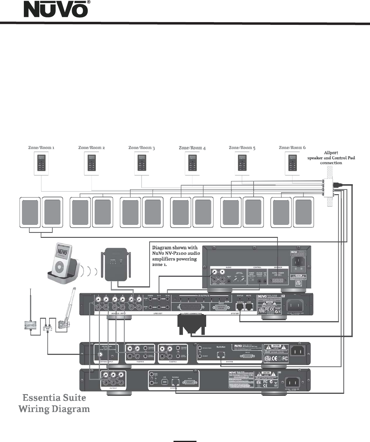
Installing the Essentia System in Your Home
3
Introduction
Congratulations on the purchase of NuVo's new Essentia System. Essentia provides 40 startlingly clear watts of sound to up to 12
listening zones(12 zones with the addition of the expander). NuVo's Generation D amplification uses the latest in digital
technology to provide peak performance in a system that sets a new standard for efficiency and energy conservation. Essentia is
the first distributed audio system of its type to bear ENERGY STAR®. This means it consumes less than 1 watt of power in standby
mode. Even with all the zones turned on and in full operation, the Essentia System's efficient design sets a new standard in low
power consumption.
Essentia truly offers the best in affordable distributed audio for the home. NuVo's state-of-the-art NuVoNet communication
through Essentia's award winning Control Pads allows you to interact with your source equipment as if you are standing at your
equipment rack. Essentia is a music entertainment system like no other multi-source, multi-zone audio system in its class.
4
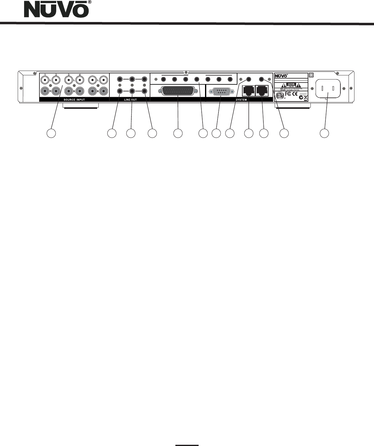
Essentia Back Panel
1. The Essentia will accept up to six audio sources. These are connected to Essentia's main and expander amplifiers
with standard stereo RCA cables.
2. These preamp lineouts are used for sending an audio signal to an external power amplifier. This is useful for
large areas that require additional pairs of speakers. These outputs are constant, so an amplifier connected to it will not
change volume with that zone's Control Pad. Zones 1 and 2 both have a fixed lineout.
3. These preamp lineouts are also used for sending an audio signal to an external power (needs left justified)
amplifier. Use the variable output when you want the volume of the additional amplifier to be controlled by the zone's Control
Pad. Like the Fixed Lineouts, zones 1 and 2 each have a variable lineout.
4. These 5-volt outputs are zone - specific voltage triggers for external amplification.
5. This 25-pin connection consolidates the zone speaker connections to the back of the Allport hub into a
single cable connection on the back of the Essentia amplifier.
6 IR signals received from the Control Pads are passed through the IR outputs to the source equipment using
the supplied IR emitters. Outputs 1-6 are routed to the corresponding sources, and the SUM output is common and will pass all
IR signals.
7. The 9-pin RS232 connection is a bi-directional serial port that allows the Essentia System to be controlled by an
external home automation device. It is also used for configuration programming download.
8. This is a constant 5-volt output for triggering external equipment. There is no voltage output when the zones are off.
9. This RJ45 connection is the input for all zone information coming from the Essentia Control Pads and all
communication with the NuVoNet Suite source components. This connection is made using the supplied pre-terminated CAT5 or
any network CAT5 cable.
10. This RJ45 output is designed to connect to the Link input on the Essentia Expander component and transfers all zone
control commands from the Main Unit's NuVoNet or RS232 command input to the Expander for an additional six zones.
11. This input is designed to temporarily mute any audio playing through the system when the doorbell or phone rings. This
works in conjunction with the NuVo NV-MI1 mute interface accessory. It also acts as a trigger for whole house paging through
any third party paging device when set for this function in the Configurator Software.
12. A detachable power cord connects the system to an external AC power supply.
Source Inputs:
Fixed Lineouts:
Variable Lineouts:
Zone Trigger Outputs:
Allport Connection:
. IR emitter Outputs:
RS232:
Status:
NuVoNet:
Link:
Mute:
AC:
56 FIXED VAR
ZONE
1
TRIG
ZONE
2
STATUS
NuVoNet
RS232
1SUM
ALLPORT CONNECTION
IR OUTPUTS
23456 LINK
MUTE
MADE IN CHINA
100~240V 50~60Hz 130W
1807
N1839
www.nuvotechnologies.com
MODEL NV-E6GM
SIX SOURCE SIX ZONE
AUDIO DISTRIBUTION SYSTEM
3033118
NuVo Technologies LLC Hebron, Kentucky USA•
CONFORMS TO UL
STD.60065 CERTIFIED
TO CAN/CSA STD.
C22.2 No.60065:03
RoHS
12345678910 11 12
5
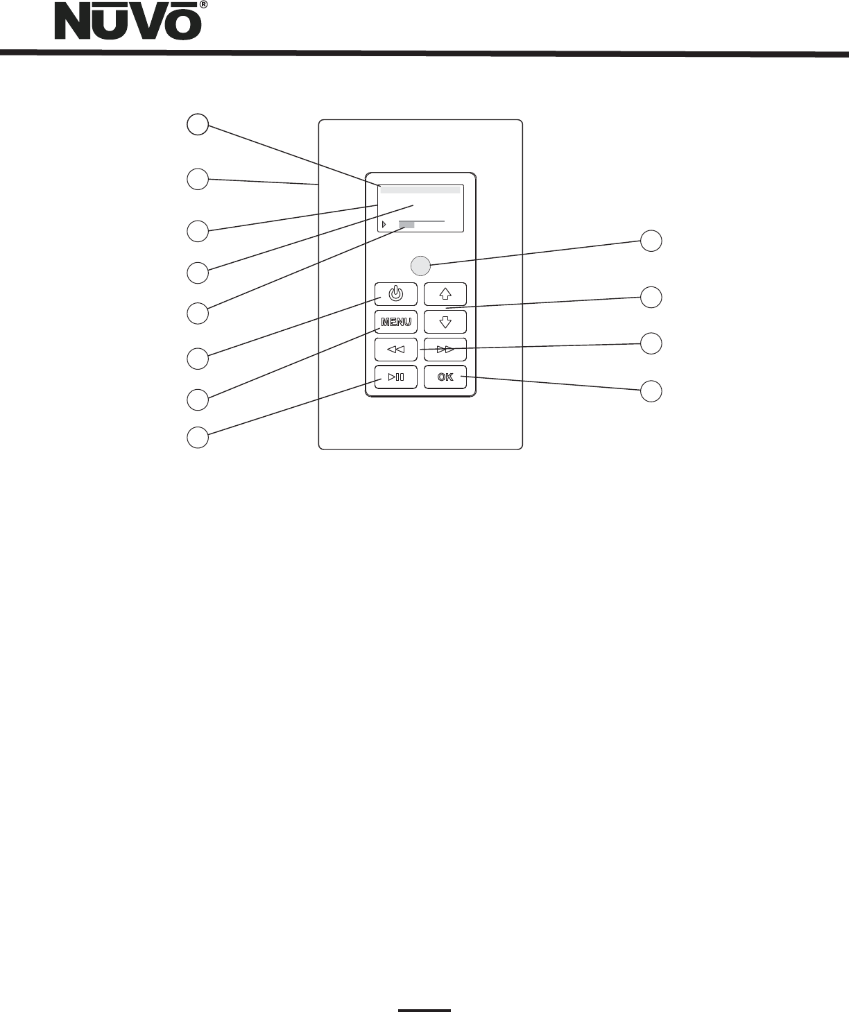
Essentia Control Pad
1. This indicates the current audio source playing in that zone. Source names can be customized in the
Configurator Software with a three-character designation.
2. Each Control Pad comes with white, ivory, almond, and black trim plates that offer a screwless and elegant,
finished installation.
3. The organic light emitting diode display is a highly functional and vivid multi-line display.
4. This portion of the display serves two functions: In normal operation, it indicates the artist,
station, metadata, and other source information, and in Menu mode, it displays multiple lines of information for browsing
purposes.
5. This bar graph indicates the audio volume level when the Control Pad is in normal play mode.
When in Menu Mode, it indicates the playback status of digital music files from the M3 audio server or iPod.
6. This button turns the local zone on and off and has the ability to turn all zones off simultaneously.
7. Menu serves as access to music browsing, presets, and favorites, as well as specific zone and system setting
parameters.
8. This IR - programmable button toggles between the play and pause functions of the chosen source. When using
the T2G Tuners, this button toggles through the Tuner's receive modes. A third “press and hold” function can also be assigned
to this button for additional functionality.
9. The OK button serves a dual function. In normal play mode, it scrolls through the available audio sources. In Menu mode, it
is used to select the highlighted menu item.
10. This is an IR - programmable button for simple source transport functions. Typically, it would track forward
and back or tune up and down. A third “press and hold” function can also be assigned to this button for additional
functionality.
11. These arrows have a dual function. In normal play mode, they control the volume level up and down. In
Menu
mode, they scroll up and down through menu selections.
12. The Control Pad has a built-in IR receiver for complete wireless control of all the audio source equipment.
Source Indicator:
Wall Plate:
OLED Display:
Now Playing/Menu Display:
Volume Level Indicator:
Power:
Menu:
Play/Pause:
OK:
Forward/Reverse:
Arrow Up and Down:
IR Receiver:
M3A
1:19 3:48
2 OF 2-Follow th...
drift-Edge of Tom
1
2
3
4
5
6
7
8
9
10
11
12
HOLD
ALL OFF
NV-GRC1
REMOTE CONTROL
FAVORITES
VOLUME
123
456
789
11
10 12
SOURCE/OK
PWR MUTE
SLEEP
DISP
MENU
G2
G1
F1 F2
F3 F4
1
2
3
4
5
6
7
8
9
10
11
12
13
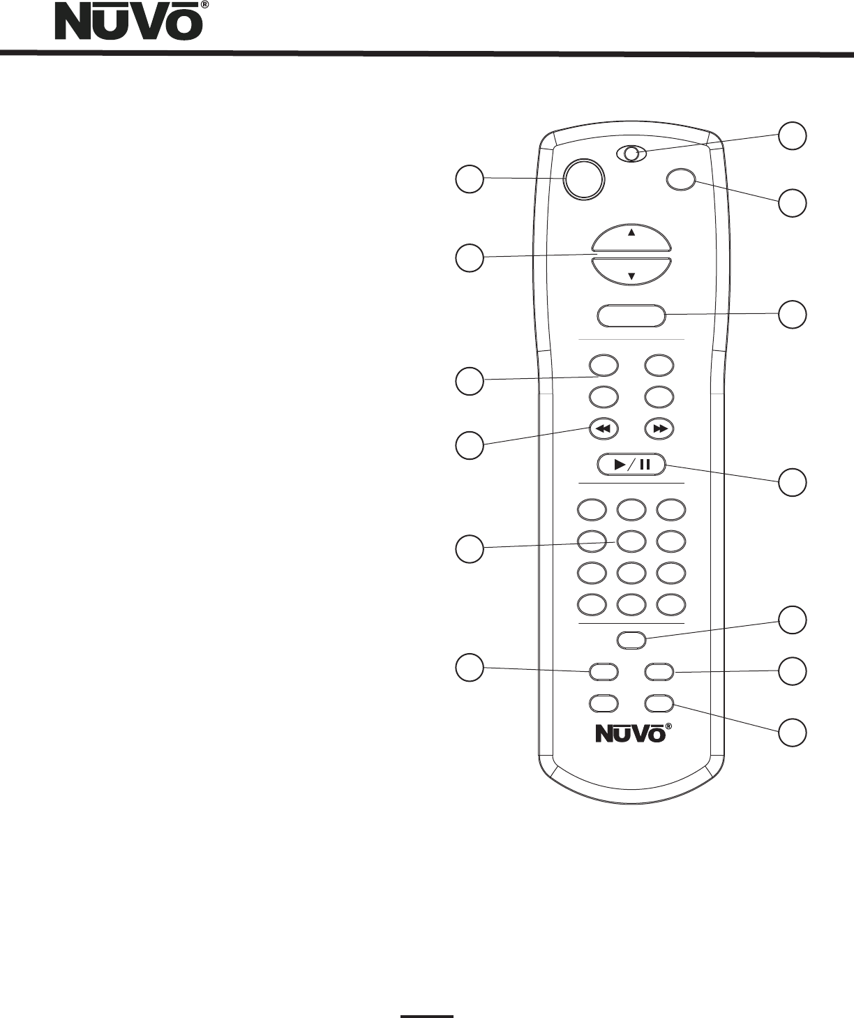
NV-GRC1 Remote Control
6
1. Power:
Volume:
Function Buttons:
Forward and Reverse:
Favorites:
DISP:
Function LED:
MUTE:
SOURCE/OK:
Play/Pause:
MENU:
Sleep:
G1 and G2:
Each zone can be turned on and off, or all
zones can be turned off with this button.
2. This serves two functions. In normal
operation mode, it is a volume control, but when
you are using the menu features of the Control Pad,
it allows scrolling up and down.
3. These buttons are currently
inactive and designed for future use.
4. These IR programmable
buttons are designed for forward and reverse
functions.
5. A function of the Essentia System is the
ability to access user defined favorites for easy
access. The first twelve are directly accessible using
the GRC1 Favorites buttons.
6. This button allows access to the Display menu
available at each Control Pad.
7. This LED (Light Emitting Diode) lights
to indicate a button push.
8. The GRC1 remote provides a discrete mute
function to quickly silence the zone's output.
9. This is another dual function button. In
normal playback mode it scrolls through the
sources, or in menu mode it selects a highlighted
menu choice.
10. This IR programmable button toggles
between the play and pause functions of the chosen
source. When using the T2G Tuners, this button
toggles through the Tuners’ receive modes.
11. This button enters the menu features of the
Control Pad. When in Menu, mode the Volume up
and down buttons scroll through the menu choices.
12. This allows access to the sleep timer mode.
13. These buttons are currently inactive.
They are designed for future use.
Installing the Essentia System in Your Home
I. Prewire
The Essentia System uses CAT5 cable for Control Pad control and either two or four-conductor 16-gauge speaker wire. All the wire
is “homerun” from each zone to the location of the Essentia amplifier and Audio Source equipment.
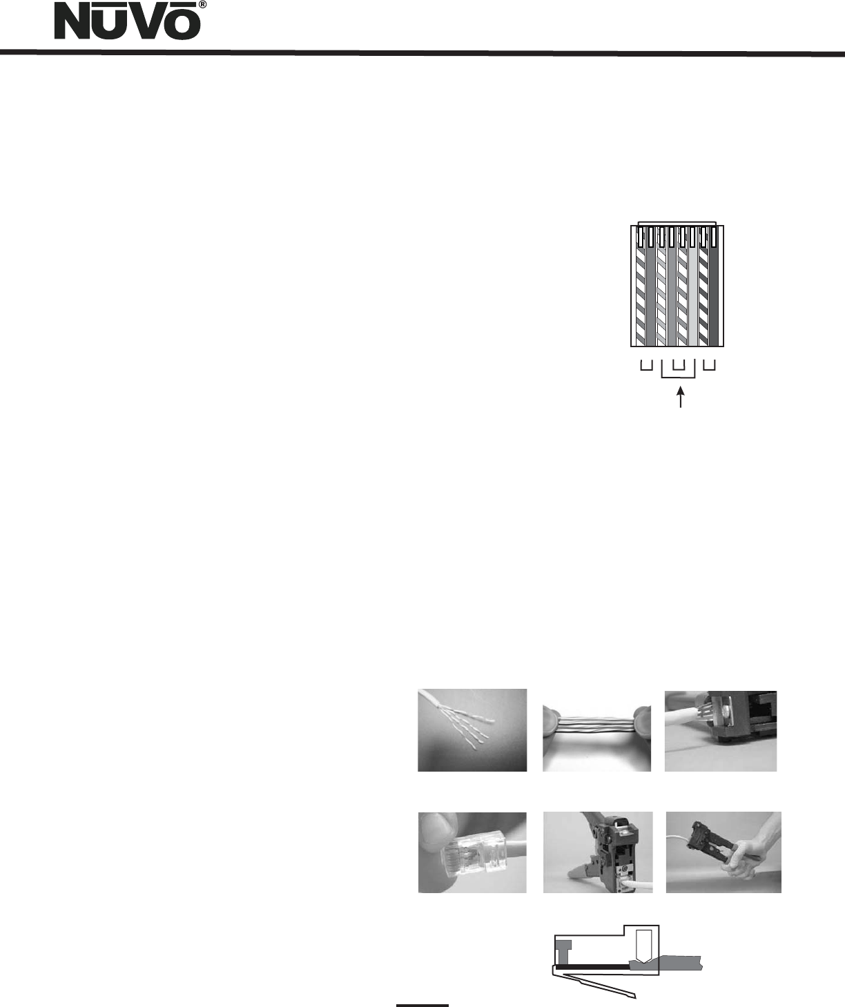
Complete CAT5 Crimping Instructions
The NuVo audio systems require CAT5, unshielded, twisted
pair (UTP) for communication between the Control Pads and
the main amplifier unit. Each end of the wire is terminated
with an RJ45 connector.
The Essentia System can accommodate 2,000 total feet of
CAT5 cable. For the most reliable operation, it is best that no
single run of CAT5 exceeds 250 feet.
The correct wiring scheme for the CAT5 cable is standard
EIA/TIA 568A, or 568B. Properly terminating the CAT5 cable
is crucial for the operation of the system. It is very
important to use a good quality crimp tool, and test each
end to end run with a CAT5 wire tester to insure that your
system operates flawlessly, Fig.1.
1. Stripa2to3inch portion of the insulation,
exposing the 4 twisted pairs.
2. Untwist the wires and fan them out
individually. Arrange the wires into the
correct color scheme as shown in Fig. 1.
3. Flatten the wires in their correct order and trim
them evenly across the top. Most crimp tools have
a wire trimmer built-in. It is best to trim the wires
to about ½” in length.
4. While holding the wires flat between your thumb
and forefinger, insert the wires into the RJ45
connector so each is in its own slot. Push the wire
into the RJ45 so all 8 conductors touch the end of
the connector. The insulation jacket should
extend beyond the crimp point of the RJ45.
5. Insert the RJ45 into the crimp tool receptacle and
squeeze the tool firmly. Note that a ratchet type
tool should tighten down until it no longer clicks.
6. The RJ45 should be firmly crimped to the CAT5
insulation. It is necessary that the color scheme
be repeated identically on each end of the wire.
7. Test each termination with a CAT5 Tester before
completing the installation.
Step-by-Step Crimping Instructions:
Fig. 1: EIA 568A and 568B wiring scheme for CAT5 Cable
Pin#568A
1. Green Stripe
2. Green
3. Orange Stripe
4. Blue
5. Blue Stripe
6. Orange
7. Brown Stripe
8. Brown
Note: Colors listed as “stripe” are a white wire
with a colored stripe.
Step 1 Step 2 Step 3
Step 4 Step 5 Step 6
12345678
Top view with
tab down.
Wires insert from
this end.
Pair 2
Pair 3
Pair 4
Pair 1
IR Active
Ground
Control Data Bus-
Control Data Bus+
IR Data
Ground
+20V Power
7
Pin#568B
1. Orange Stripe
2. Orange
3. Green Stripe
4. Blue
5. Blue Stripe
6. Green
7. Brown Stripe
8. Brown

--
++
LEFT
RIGHT
LEFT RIGHT
8
II. Terminating the Speaker Wire (Fig. 2)
All NuVo Systems operate across a “homerun” wiring scheme
using CAT5 for the zone's Control Pad communication and
control, and a separate run of speaker wire for each zone.
The Essentia operates differently in that its zone speaker
wire termination is made at the Allport hub. The suggested
wire for this purpose is 16-gauge, 2- or 4- conductor
speaker wire rated for in-wall use.
The termination is performed using a modular “Euro”
connector. Each conductor is screwed down to the Euro
connector and plugged into the appropriate zone speaker
connection on the back of the Allport. The proper
termination for each zone is Left channel: — and , and Right
channel: — and .
+
+
IThe order in which the CAT5 cables are plugged into the
jacks is irrelevant to the system's operation. Six modular
“Euro” connectors are used to terminate the speakers in
each zone, see Section II, Terminating the Speaker Wire.
Once the speaker and CAT5 terminations are complete, the
Allport can be installed.
Fig. 2
III. Installing the Essentia Amplifier
System setup works best when the amplifier is placed in the
same location as the audio source equipment. This is
typically in an audio rack, entertainment center, or a closet
dedicated to housing the home audio/video equipment. To
insure cool, reliable operation, we highly recommend
allowing one empty rack space above a Main or an Expander
amplifier unit. Also, insure there is ventilation around the
whole rack location.
The amplifier should be plugged in and the blue Standby LED
should be lit before proceeding with the remaining
installation. This activates protective circuitry for the
internal components.
IV. Installing the NV-E6GMAP-DC Allport (Fig. 3)
The Allport is a multi-connection hub designed to accept all
the CAT5 and speaker wires from all zones of the Essentia
System. The location of the Allport should be determined by
the location of the Essentia amplifier. It is best to place it in
a wall behind the amplifier that can be easily accessible if
necessary.
The Allport is designed to fit into most any dual-gang
mounting ring, and has two sets of terminations on the
backside. Eight RJ45 jacks are meant for the Control Pads in
up to six zones, with one reserved for an additional Control
Pad and another for a “link” jack used for expansion from six
to twelve zones.
Fig. 3
+
+
+
+
+
+
+
+
+
+
+
+
+
+
9
V. Connecting the Allport to the Essentia Amplifier (Fig. 4)
Once installed, the front of the Allport has three “Device”
RJ45 jacks for CAT5 connections from the NuVoNet Suite
components, and an RJ45 jack labeled “NuVoNet” which
must be connected to the “NuVoNet” input on the back of
the Essentia amplifier. This is necessary for Control Pad
communication, regardless the use of the NuVoNet Suite
components. Once connected, the Control Pads are ready to
communicate with the System. The Essentia System is
shipped with a six-foot pre-terminated CAT5 network cable,
or you can purchase one if a different length is required.
The speaker connection is made with the 25-pin Allport
Cable. The modular speaker connectors must be plugged into
the appropriate speaker connections on the back of the
Allport.
Fig. 4
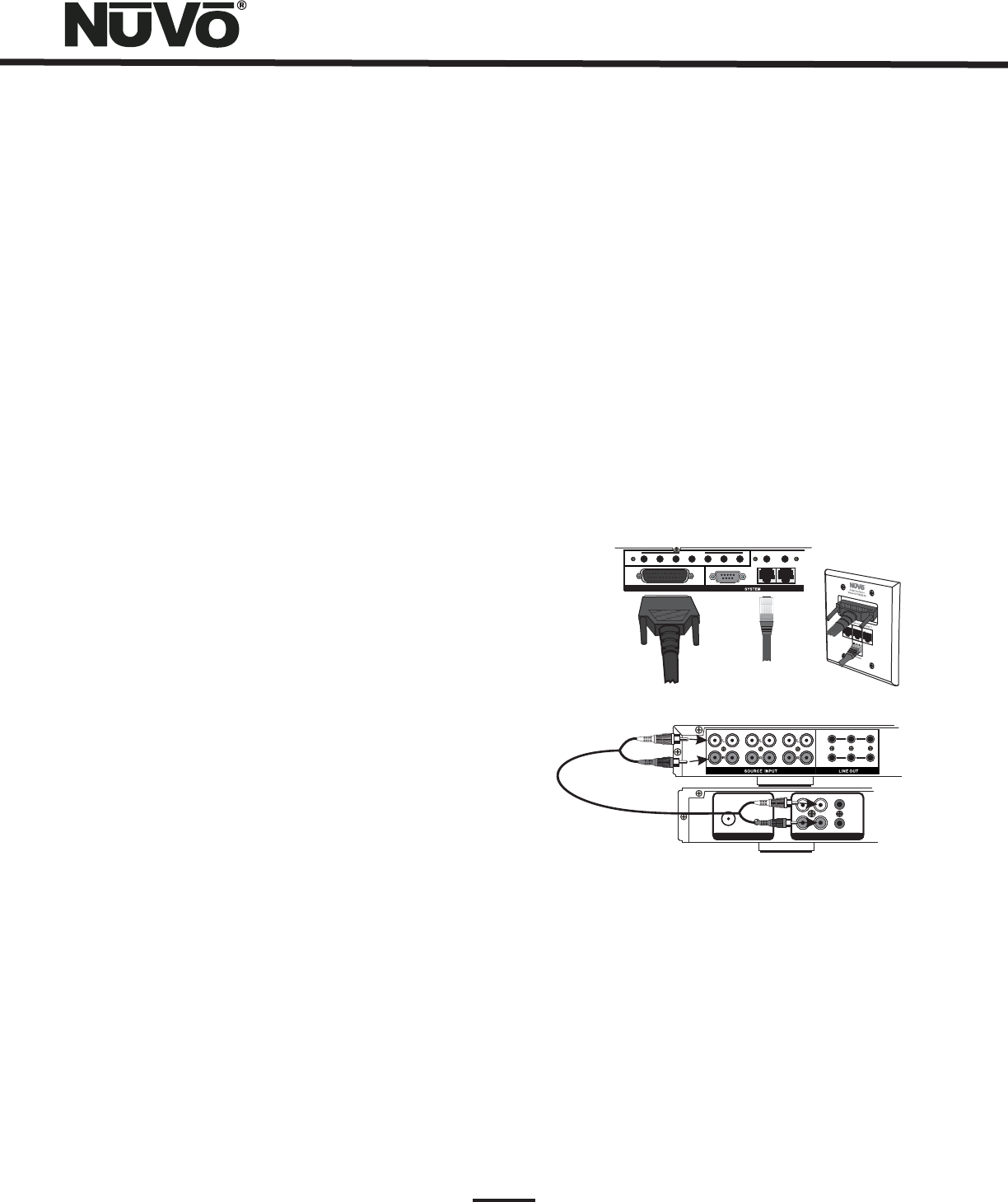
VI. Attaching Audio Source Equipment (Fig. 5)
Each piece of audio equipment is connected to the Essentia
amplifier with standard stereo RCA cables. Attach an RCA
cable to the corresponding audio output on the source
equipment and to the desired source input on the back of
the Essentia amplifier. The numbered input for each source
is important in the configuration of the system. This will be
covered in detail in the Essentia Configurator portion of this
manual.
The Zone 1 and 2 outputs have 3.5mm stereo pre-amp
lineouts attached to them. Their purpose is to provide the
zone’s current audio selection signal to an additional
amplifier. Both versions, fixed (a constant signal that
requires a volume control separate from the NuVo zone
Control Pad) and variable (a signal that varies in level
relative to the volume setting on the NuVo zone Control Pad)
are both simultaneously active and require no external
switch for use.
Each output has an attached voltage trigger output that
allows the attached amplifier to be triggered from a voltage
presented when the zone Control Pad is turned on. The
voltage trigger is removed when the zone is truned off.
Using the Fixed and Variable Lineouts
TUNER BTUNER BANTENNA INPUT
IN
USE ONLYNuVo
NV-T2PAS
POWERED ANTENNA SYSTEM
USE ONLYNuVo
NV-T2PAS
POWERED ANTENNA SYSTEM L
AUDIO OUTAUDIO OUT
AUX INAUX IN
R
TRIGGER
ON=+12V
TRIGGER
ON=+12V
AUDIO
OUTPUT
AUDIO
OUTPUT
FIXED VAR
ZONE
7
TRIG
ZONE
8
78 910 1112
Fig. 5
T2G AM/FM and XM Tuners
OPERATING MODE
STAND ALONE, SOURCE 6, SOURCE 5, SOURCE 4,
SOURCE 3, SOURCE 2, SOURCE 1.
Each of the T2G Tuner components houses two individual
AM/FM or Satellite receivers, which have their own display
on the front panel. Once the T2G is plugged in and the
NuVoNet CAT5 is connected to the Allport, the initial display,
will appear for each tuner. Below this, the
choices are
and Stand Alone is
automatically highlighted at initial startup. Selecting the
appropriate Essentia source input is accomplished by
turning the Select knob for each tuner counter-clockwise
until the desired source input number is highlighted. It is
selected by pushing the Select knob. Once this is complete,
the Essentia System NuVoNet will recognize that source.
STATUS
NuVoNet
RS232
1SUM
ALLPORT CONNECTION
IR OUTPUTS
23456 LINK
MUTE
ALLPORT CONNECTION
Setting up NuVo Sources for use with NuVoNet
X. Essentia Configurator Software.
A feature of the Essentia System is its ability to
automatically communicate with the T2G family of tuners,
the M3 Audio Server, and the Wired and Wireless NuVoDocks
for iPod. The communication happens through the Allport
connection hub across a communication protocol called
NuVoNet. Although software programming is not necessary
for this function, configuring the installation through the
Configurator Software prior to installation has distinct
advantages, see
When the T2G tuners or M3 Server are plugged in for the first
time, they will display a prompt to select a source input
number for the Essentia. For NuVoNet to communicate
properly, you should have already connected the NuVoNet
components to one of the three “Peripheral Device” inputs
on the face of the Allport.
10
M3 Audio Server and T2SIR Dual Sirius Ready Tuners
Status, all outputs.
OUTPUT A: PRESS OK TO SELECT NUVONET
SOURCE.
Address, Output A, STANDALONE
SOURCE 1, SOURCE
2. . . SOURCE 3,
SOURCE 4, SOURCE 5, SOURCE 6
At initial startup, the front panel display will display a
prompt screen Below this header are
three lines of text representing each of the three audio
outputs labeled A, B, and C. Output A will be highlighted and
it will display
When OK is selected, the top line of the display will
read below this, will be
highlighted and the other choices will be
and as you scroll using the down arrow,
and will appear. Highlight
the appropriate choice and press OK to select. This will set
the first channel music output. You will then be prompted to
repeat these steps for the remaining two channels.
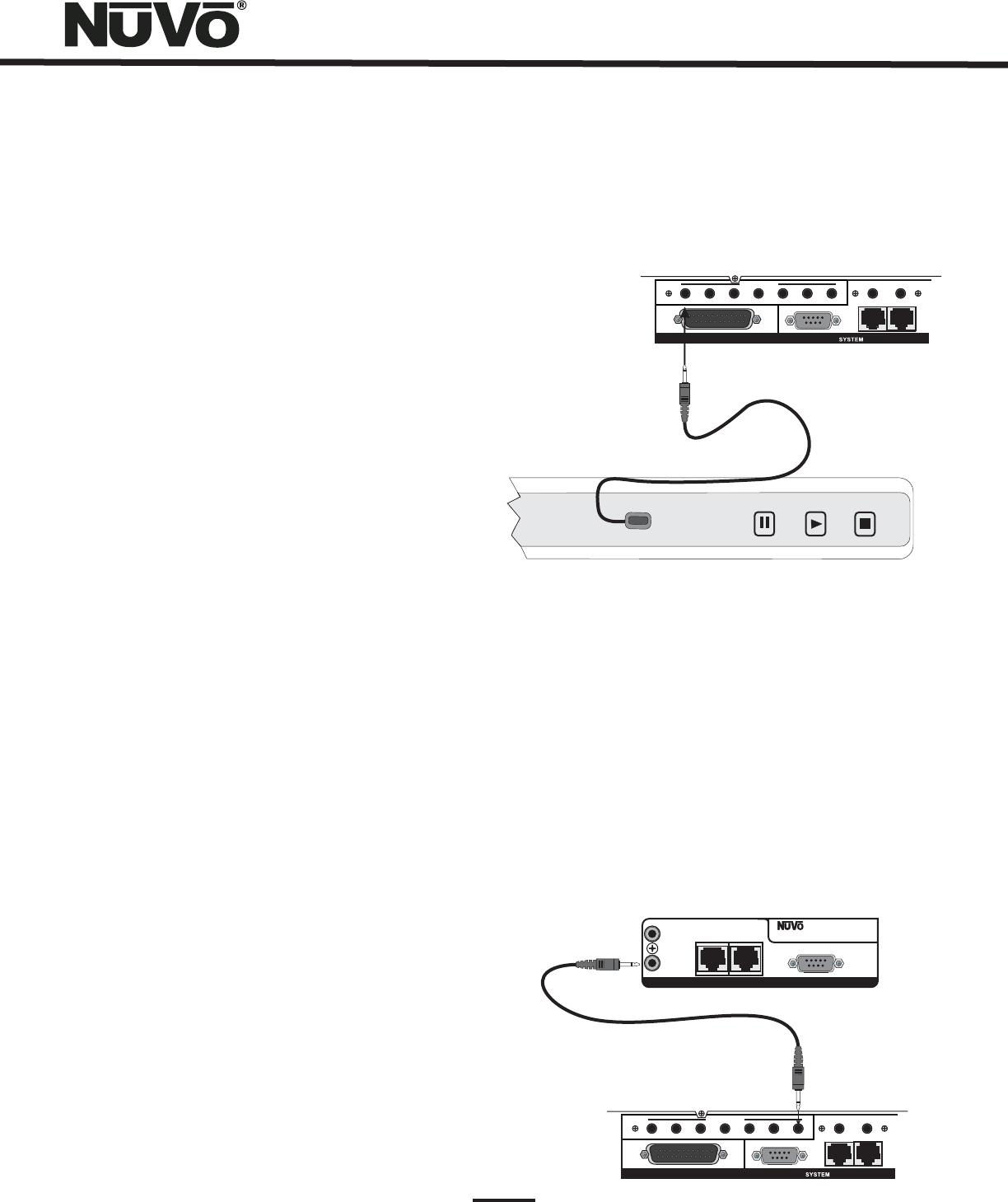
VII. Connecting the IR Emitters for Third-Party Source
Components (Fig. 6)
IR commands for the source equipment are transferred from
the Essentia amplifier to the source equipment using the
mini IR mouse emitters. Six of these are supplied with your
Essentia System. The emitter is plugged into the
corresponding source IR output on the Essentia and then
placed over the IR receiver window on the source
component. The IR outputs are individually routed to
sources 1-6.
Fig. 6
NuVoDock for iPod
Note that although the NuVoDock system has a 16 position
rotary switch for source input, only positions 1 – 6 are used.
Both the Wired and Wireless NuVoDocks for iPod use a
simple rotary switch to set the appropriate source input. Up
to two Wireless NuVoDocks and six Wired NuVoDocks could
be used as individual sources through NuVoNet. The Wired
and Wireless NuVoDocks consist of a dock for iPod playback
and recharging as well as a receiver component designed to
communicate with NuVoNet. Prior to plugging the receiver
into the Essentia Allport, set the Source rotary switch to the
desired source number input. Once set, theEssentia Control
Pads will automatically display the iPod information when an
iPod is plugged into the NuVoDock. Each NuVoDock and
receiver must have a separate source number selected.
The two SUM outputs will flash any IR command that is sent
from any of the zones. This is most commonly used with an
IR blaster designed to flash IR commands to a variety of
components.
STATUS
NuVoNet
RS232
1SUM
ALLPORT CONNECTION
IR OUTPUTS
23456 LINK
MUTE
ALLPORT CONNECTION
dISC
COMPACT
NuVo T2G Tuner Direct Numeric Access (Fig. 7)
The NuVo T2G Tuners have the ability for direct IR access to
numeric station tuning. This can be done through the T2G
remote control or using a third party remote control that has
been taught the T2G IR codes. To allow this control, it is
necessary to link the Essentia SUM IR output to the Direct IR
input on the T2G using a stereo 3.5mm (1/8”) mono patch
cable. Once the connection is made, the T2G will respond to
the numeric IR commands issued through the Essentia
Control Pad IR receivers.
Fig. 7 T2G Tuner IR Input
Essentia IR Ouput
Model NV-T2DF
Dual XM Tuner
NuVo Techonlogies LLC•
Cincinnati Ohio USA
www.nuvotechnologies.com
SYSTEM
IR PASS-THRU
IR INPUT
NuVoNet
OUTIN
RS232
STATUS
NuVoNet
RS232
1SUM
ALLPORT CONNECTION
IR OUTPUTS
23456 LINK
MUTE
ALLPORT CONNECTION
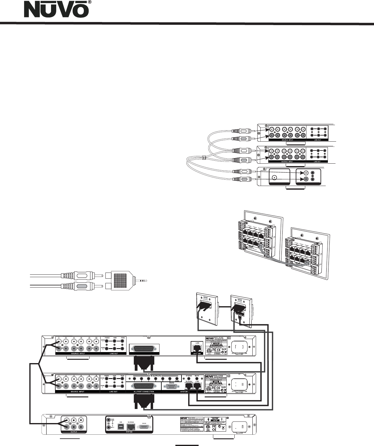
VII. Expanding Essentia to 12 Zones (Fig. 8)
Six additional listening zones can be added to the Essentia
System using the Essentia Expander System, NV-E6GXS. The
expander requires the use of the Link RJ45 connection on the
main amplifier. This is connected to the corresponding Link
RJ45 connection on the expander amplifier. All of the upper
zone control commands from the main unit's NuVoNet or
RS232 command input are transferred through this
connection. The NV-RCA3 Y-adapter cables included with
the expander unit allow a parallel connection of the left and
right source output to the corresponding source inputs on
both amplifier units, fig. 8a.
The expansion requires the installation of the expander
Allport included with the expander system. The expander
Allport is the connection for the additional zone Control
Pads, up to seven, and the additional zone speakers. A
second Allport cable must be attached from the expander
Allport to the expander amplifier and a short CAT5 jumper
cable, included with the expander system is used on the
back of the two Allports to integrate all of the System’s
Control Pads into one NuVoNet connection to the main
amplifier, Fig. 8b.
Once these connections are complete, the Control Pads can
be addressed for a twelve-zone system.
Note: If you are using the Remote (wired) or Wireless
versions of the NuVoDocks for iPod, it is necessary to use a
female to male adaptor. These are readily available and are
not supplied with the NuVoDock system, fig. 8c.
+
+
+
+
+
+
+
+
+
+
+
+
+
+
+
+
+
+
+
+
+
+
+
+
Fig. 8b
E6GXAP-DC
Expander Allport Hub
E6GMAP-DC
Main Allport Hub
11
Fig. 8a
NV-RCAY3 “Y” cable
TUNER BTUNER BANTENNA INPUT
IN
USE ONLYNuVo
NV-T2PAS
POWERED ANTENNA SYSTEM
USE ONLYNuVo
NV-T2PAS
POWERED ANTENNA SYSTEM
AUDIO OUTAUDIO OUT
TRIGGER
ON=+12V
TRIGGER
ON=+12V
AUDIO
OUTPUT
AUDIO
OUTPUT
FIXED VAR
ZONE
1
TRIG
ZONE
2
12 34 56
FIXED VAR
ZONE
7
TRIG
ZONE
8
12 34 56
Essentia G Expander
Essentia G Main
Audio Source
Fig. 8c
Fig. 8
ALLPORT CONNECTION
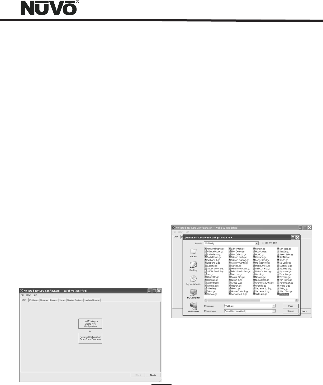
IX. Using the Essentia Configurator Software
1. Main Startup (Fig. 9)
The following section includes the optional NV-I8DLS IR
Learning Station. This is available as a package from NuVo
Technologies or any Authorized NuVo Distributor. The
Configurator Software is a PC program designed to run with
Windows 2000, XP, and XP Pro.
The Configurator is a tabbed Wizard-style interface
designed to sequentially walk the installer through the
system setup for both the Grand Concerto and Essentia.
When the program is launched, the Start tab is highlighted.
Clicking View and selecting E6G Mode tailors the
configuration for Essentia. The Start Tab gives three choices
for beginning a configuration. You can create a new file,
open an existing file, or retrieve an existing file from a
configured Essentia System.
Once configured, the finished program loaded into the
Essentia main amplifier can always be retrieved via the
RS232 port and has the ability to be edited.
Once a configuration file has been opened, you can then
click on the next button to continue. The Configurator will
not let you continue beyond Start without either creating a
new file or opening an existing file. It will also prevent
moving forward through any of the tabs until the necessary
information is completed in any one of the tabs.
Fig. 9
1.1 Open or Create Essentia Configurator File (fig. 10)
1.2 Retrieve Configuration from Essentia
When you click on this button, the program goes to a Config.
File. There you can either open one of the existing
configurations or specify the name of a new file.
Configurations are saved with a .cfg extension.
To retrieve a configuration from an existing Essentia
installation, launch the Configurator Software. Make sure
your computer is connected to the RS232 port on the back
panel of the Essentia amplifier. The Startup screen has two
buttons. The first is used to open an existing configuration
or to create a new one. The second asks to “Retrieve Existing
Configuration From Essentia.” When you click on the
“Retrieve” button, a progress window will appear.
If you have this configuration already stored on your
computer's hard drive, you will see a dialog box asking if
you wish to overwrite the existing file. If this file is not
stored in your computer, this box will not appear.
Fig. 10
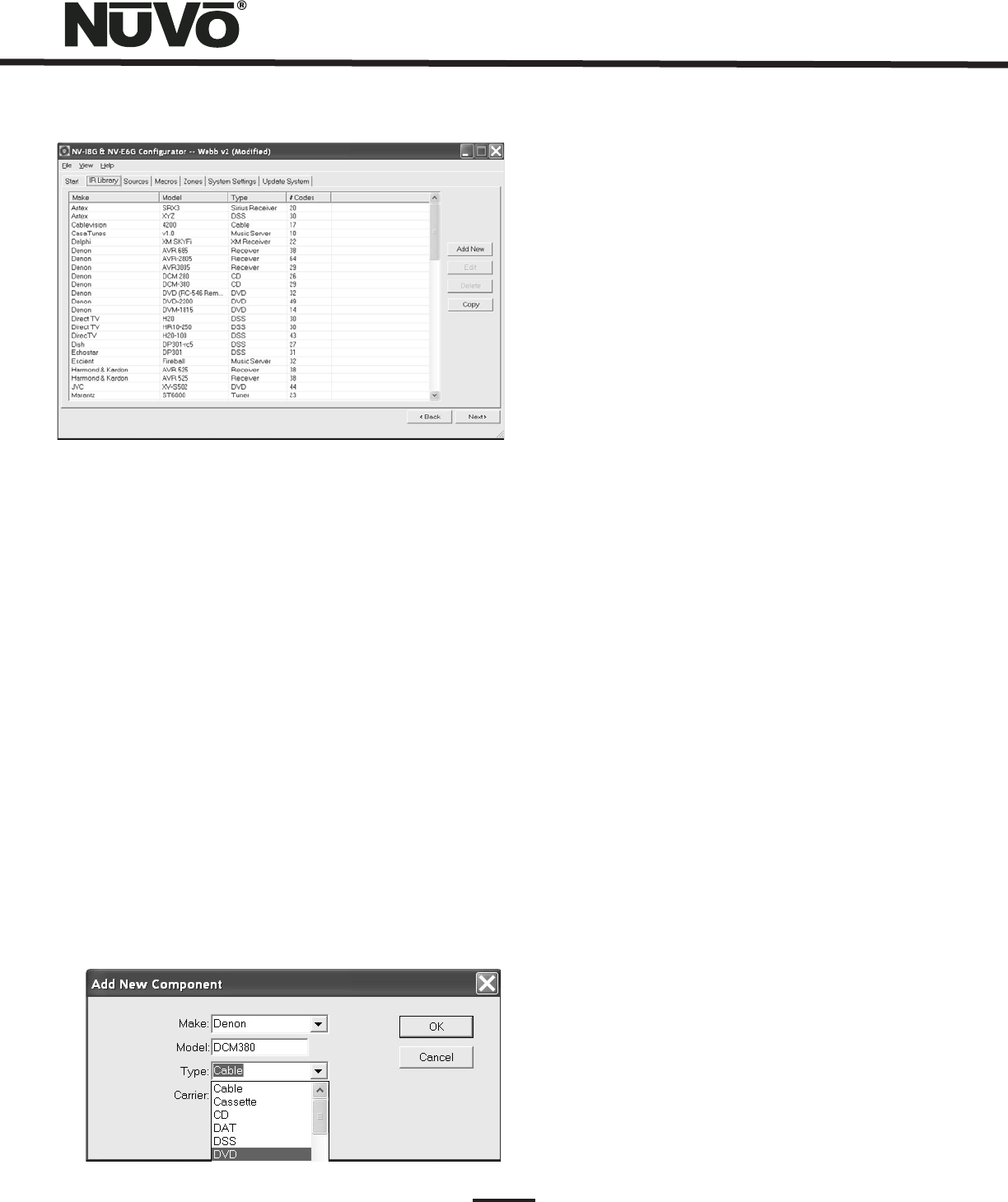
2. IR Libraries (Fig. 11)
The IR Library is a list of available components and their IR
function codes. The Configurator Software stores captured IR
codes in a single directory. Once captured or downloaded,
the Configurator Software will permanently store it as a .gcl
file.
12
13
Fig. 12
Fig. 11
2.1 Adding a New Component to the IR Library (Fig. 12)
New component IR files are easily added by clicking on the
Add New button. This brings up a new window titled Add New
Component. In this window you must first enter the
manufacturer name and model. The Type drop-down menu
contains a large list of components. Each is a template of
common functions for that type of equipment. Clicking on
the type that matches the component will add the type name
in that field. If desired, you can add a type name that is not
in the drop-down menu.
Clicking on OK will automatically add the selected
component and associated functions to the IR Library.
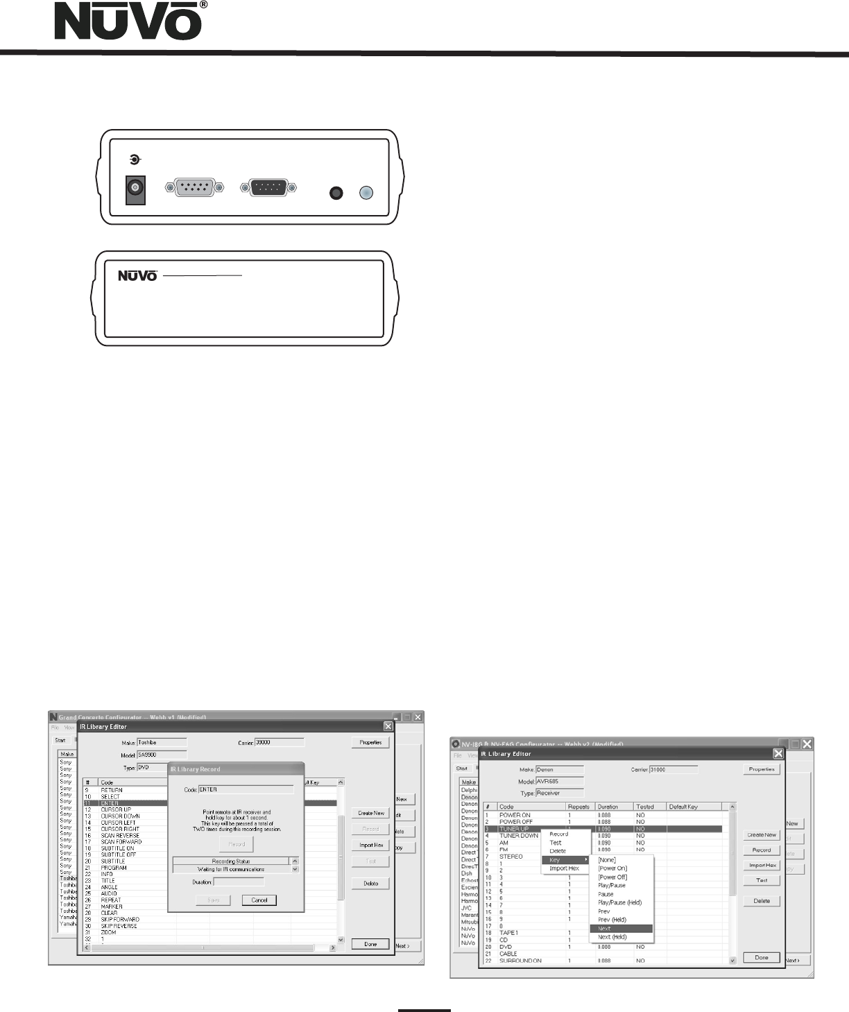
Using the IR Learning Station Interface (Fig. 13)
To record new IR codes, you will need the IR Learning Station
Interface. The IR Learning Station Interface is a powerful
tool for setting up new IR Libraries for use with the
Configurator Software, and is part of the IR Learning Station
Package. Capturing function codes and adding them to the
component IR Library is an easy process.
The Interface box is connected to your computer using one
of the RS232 connection cables provided with the IR
Learning Station package. Note that in many cases, personal
notebook computers do not have a Db9 serial cable. In this
case an RS232 to USB dongle cable will be necessary.
The back panel of the Interface box has two IR outputs for
testing purposes. You can use the included IR emitter and
attach it to the IR window on the face of the source
component, or to the built-in IR blaster, which, when aimed
at the source equipment, will fire the IR command.
2.2 Recording IR codes (Fig. 14)
When a new component is added to the IR Library, it is
necessary to record the IR codes associated with each
function. To do this, connect the Learning Station Interface
as described above. Double-click on the desired component
from the IR Library page. This will open the IR Library Editor.
This window lists the complete set of functions for that type
of device.
To initiate the IR recording process, you can either double-
click on a function to be recorded or highlight the function
and click on the Record button. This will open the IR Library
Record window. The window will indicate that the
Configurator is “Waiting for IR Communications.” To record a
new code, simply point the component's remote control at
the IR receiver on the NuVo IR Learning Station Interface.
The first time you enter a code, the Configurator determines
if it is a “toggling function,” which means that the remote
actually sends two commands back-to-back. This requires
that the function button be pressed four times in
succession.
14
Fig. 13
+-
POWER
12VDC/0.4A
CONNECT TO
PC
CONNECT TO
CONCERTO D
IR
EMITTER
IR
BLASTER
Concerto Learning Station
Model NV-I8DLS
PASSTHRU READY IR SENSOR TEST ACTIVE POWER
When the remote code is entered, the IR Library Record
window will go from yellow to green and indicate that the
capture was successful, and it will then return to yellow.
Repeat this procedure three more times until the desired
code is added to the IR Library Edit window. You will now see
the number of code repeats and the duration of the code. A
normal non-toggling remote will require two button pushes
to successfully record a command, while a toggling remote
will require four button pushes for each command.
If there is an error in recording the code, the display in the
Record window will indicate that there was a communication
error. If this occurs, click on the Record button and reenter
the code.
Fig. 14
2.3 IR Library Default Key Assignment (Fig. 15)
Once the desired codes are added, assign them to the
appropriate key on the Control Pad. Note that by design, the
Control Pad has only 3 IR programmable function keys and
Power ON/Power Off. Access to multiple preset choices will
be covered later in the Macros section.
To assign default IR functions to the Control Pad buttons,
right-click on each code and select “Keys.” This opens a
drop-down menu of the possible key selections for the
Essentia Control Pad. Select the appropriate key for that
command and the Configurator will add it to the Default Key
field for that command. The Play/Pause, Prev. and Next
functions have an additional (Held) function. This allows an
additional function assignment that is activated when the
button is held. The Control Pad automatically displays the
function being sent to the source component.
Once this sequence is completed, proceed to the next
function command, and repeat the above steps. When you
have assigned a default key for each IR, click on “Done” and
that component's IR Library is complete.
You can also assign discreet power on and off commands.
The Essentia System will initiate the On command when a
zone is turned on and in turn initiate the Off command when
the zone All Off function (holding the Power button for three
seconds) is initiated from any of the Control Pads.
Fig. 15
15
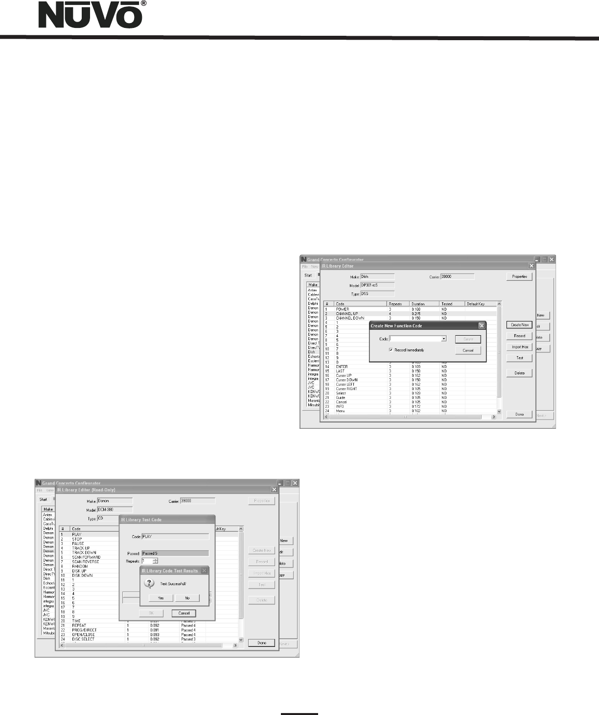
2.4 IR Library Test (Fig. 16)
An important feature of the Essentia Configurator is the
ability to test each IR code as it is added to the IR Library.
This insures that every code will work reliably.
When a new code is added, while it is still highlighted, click
on the test button, or double click on the highlighted code.
This will open the IR Library Test window. Make sure that the
IR Learning Interface box's IR emitter is either facing the IR
receiver window of the source equipment or an IR emitter is
plugged into one of the two IR emitter outputs and affixed
to the IR receiver window of the source equipment. Clicking
on the test button will cause the IR Learning interface to
emit the code. The source equipment should respond
appropriately to the command if it has been stored
correctly. A test result box will open where you can record
yes or no to the test. Three successful test results are
required before the “Passed” count turns green. Clicking
the “OK” button will save the results in the IR Library. The
“Tested” column for that command will show the number of
successful tests performed.
Although not required, testing each code is highly
recommended.
Fig. 16
2.5 Adding a Function Code (Fig. 17)
If a required IR function is not in the list of those provided in
the library template, it is possible to add a code to the list
by clicking the “Create New” button. The pull-down menu
contains a list of all standard IR codes. A name not found in
the list can be typed in, but it is recommended that you use
the names provided in the list. This conserves memory in the
Essentia. Clicking on the “OK” button proceeds directly to
the IR recording process.
Fig. 17
2.6 Cleaning Up an IR Library
Unused IR codes can be deleted from the list by highlighting
the code and either clicking the ”Delete” button or right-
clicking and selecting “Delete.”
When you are finished editing the library, select “Done.”
3. Defining Sources
The “Sources” tab allows you to define the source
component attached to each of the six source inputs. All six
sources are not needed, but at least one source must be
defined.
16
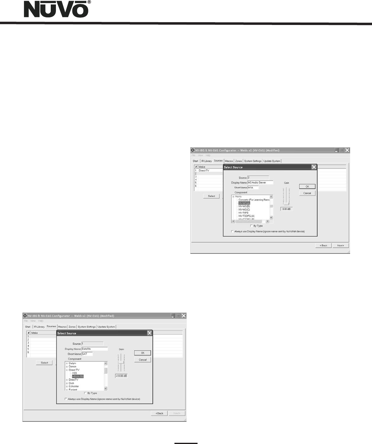
3.1 Select or Edit Source (Fig. 18)
Double-clicking on a blank source will open the “Select
Source” window. This window assigns the appropriate source
number input. The “Display Name” is the text that will be
read on the Control Pad when that source is selected in any
zone. The display name can contain only capital letters,
numbers, and some punctuation. If an invalid key is typed, it
will be ignored.
The “Make” field defines the manufacturer of the
equipment. A drop-down menu allows you to choose a
source from the IR Library. The “Model” field provides a
drop-down menu that allows you to choose the specific
piece of source equipment from the selected manufacturer.
An important feature of the “Select Source” window is the
“Gain” level control. Different pieces of source equipment
tend to have different levels of audio output signal. This
slider control allows you to compensate for equipment that
has an inherently lower volume level. By using this
adjustment, when switching between sources, relative
volume levels remain constant.
When the appropriate information is complete, click “OK.”
This will add the updated source information to the “Source”
window. When all the desired sources have been defined, go
to “Next” and proceed to the “Macros” setup.
Fig. 18
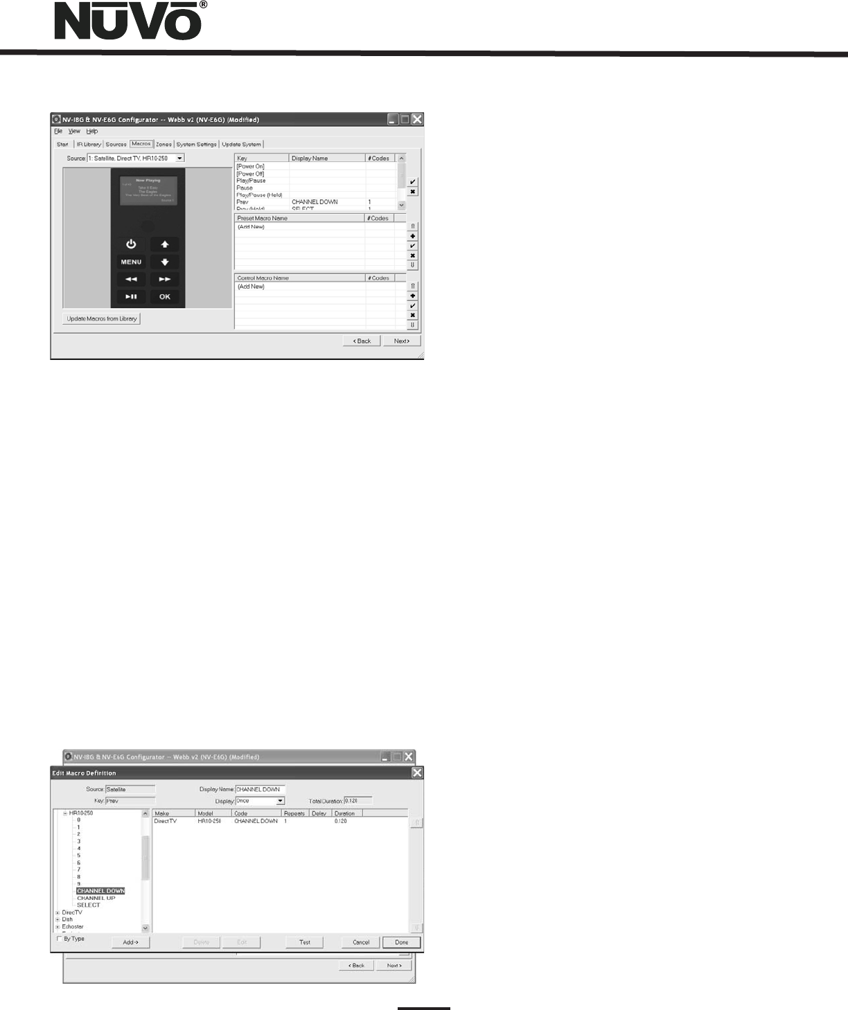
4. Macros (Fig. 20)
4.1 Edit Macro
Definition
An important feature of the Configurator program is the
ability to define source specific macro definitions for third
party IR control. The Essentia has a unique ability to store
specific IR commands as preset names. The best example is
cable or satellite. Using the Macro tab, you can establish a
preset name and set the appropriate IR commands to select
a specific station (this will be covered in the
section). Macro definition only applies to third
party non-NuVoNet sources.
Adding a NuVoNet Source (Fig. 19)
Setting NuVo Sources for use
with NuvoNet, pg.9&10.
NuVoNet sources can be placed in the Configuration with the
same procedure as third party IR controllable equipment.
The Configurator program contains IR libraries for each of
the NuVoNet components which have the appropriate button
functions pre-assigned. Even though the components are
assigned, you must still set the NuVoNet source inputs on
each of the components, see
Fig. 19
17
Fig. 20
4.1 Edit Macro Definition (Fig. 21)
The Macro tab has a Source pull down menu that displays the
six sources defined in their order 1-6. When a non-NuVoNet
source is highlighted and selected, three separate definition
windows appear on the right side of the screen. The left side
of the screen is a representation of the Control Pad display.
When the curser is scrolled over the buttons on the Control
Pad, a tool tip appears indicating the function command or
commands that have been assigned to that button. Here you
can double click on the button which opens the Macro
Definition Window. When in Macro Definition, if you choose
to, you can reassign new codes. You can also double click on
the appropriate function in the window on the right side of
the tab and access the Macro Definition window.
Fig. 21
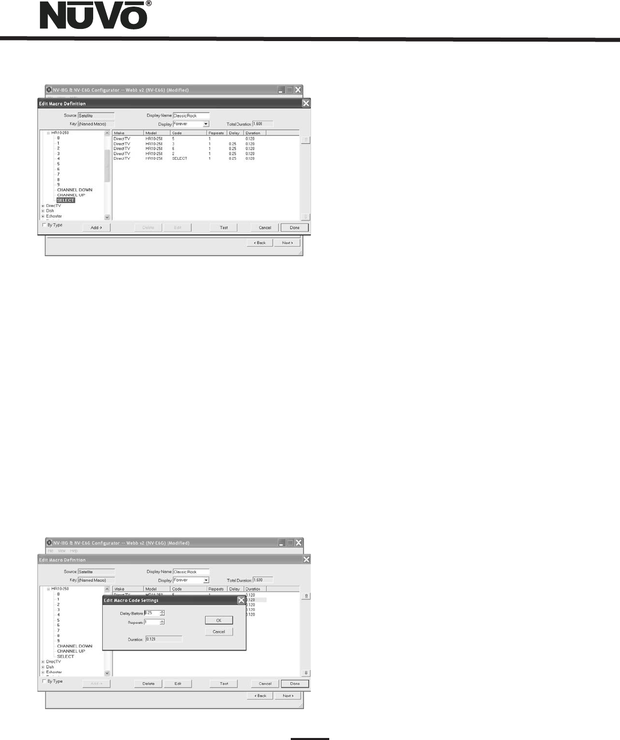
4.1 Creating a Macro Preset String (Fig. 22)
An important function of the Macro tab is to create a menu
of preset choices for third party components, such as
satellite, cable and CD changers. When a non-NuVoNet
source is selected, a Preset Macro window appears on the
right side of the screen with open spaces for storing preset
station choices. Up to 250 macros can be defined in this
window. When a preset is added to a source, an additional
Preset menu item will be added to that source browsing
capability on the Control Pads. The preset menu is preceded
by the three character source designation established in the
Source tab.
To create a preset macro, double click on the first available
preset macro selection, Fig. 20. This will open the Edit Macro
Definition window. Once in that window you must type a
name for the preset in the Display Name window, which will
establish the preset name as it will appear in the preset
menu. Note that the Display drop down menu directly below
the Display Name window defaults to Forever. This is the
desired choice for a preset and will keep the preset name on
the Control Pad while that selection is currently playing.
The available IR codes for that source will be expanded in
green on the left side of the Edit Macro Definition window.
As you double click on a code, it will automatically be added
to the macro string on the right. Up to 255 codes can be
added to a single macro and the codes will fire in the order
in which they are added to the string. Once the desired
macro string is complete, click done and return to the main
macro tab. The completed macro will appear in the Preset
Macro window. To create a second preset, double click on the
next space and repeat the Macro Definition steps.
If the component had default keys defined in the IR Library,
single IR code macros will be automatically created for each
key. Hovering the mouse over each key in the Control Pad
picture on the left side of the screen will bring up a tool-tip
displaying the name of the macro assigned to that key.
Clicking on the key highlights the macro on the right side of
the screen.
Double-clicking on a key in either display will allow you to
change the default assignment or create a new one in the
Edit Macro Definitions window, Fig. 21
18
Fig. 22
Fig. 23
4.2 Editing Codes in a Macro (Fig. 23)
When in the Edit Macro Definition window, double-clicking
on a macro step on the right side will open an “Edit Macro
Code Settings” window. This allows you to change the delay
time before the command is issued. The default delay is .25
seconds. This can be increased by .25-second increments up
to 30.5 seconds. Often a command requires mechanical
movement in the source equipment and, therefore, the
delay is important before initiating the next command.
The number of repeats for each command can also be
changed. This is equivalent to pushing the command button
on the remote control multiple times.
Re-Ordering Macro Codes
Macros (updated)
After a code is added to a macro, highlighting a code and
clicking on the or button will reorder the codes.
After editing a macro, the macro list is updated to show the
number of IR codes and the display name.
Note that the Macro tab has an additional button at the
bottom that says “Update Macros From Library.” If codes
were edited in any way in an IR library after a source has
been defined in the Source tab, this button will
automatically pull those changes into the Macro Definition
window.
Ýß
4.3 Control Macros
4.1
Creating a Preset Macro String
An additional option within the Macro tab is the ability to
establish multiple control macros. These macros are
intended for instant access to control functions and are an
optional feature. If a control macro is created, an additional
source menu item is also created titled “Control” preceded
by the three character “short name” assigned in the Source
tab.
Creating a control macro is the same process outlined in
on page 17.
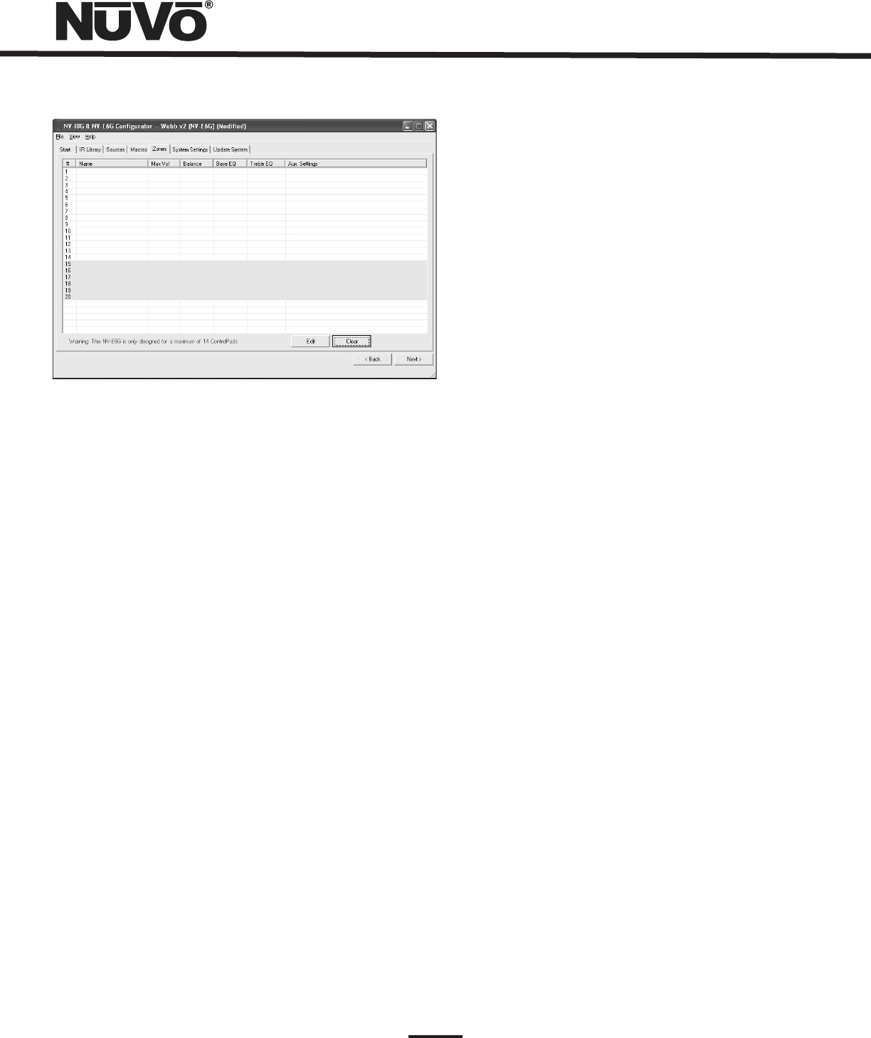
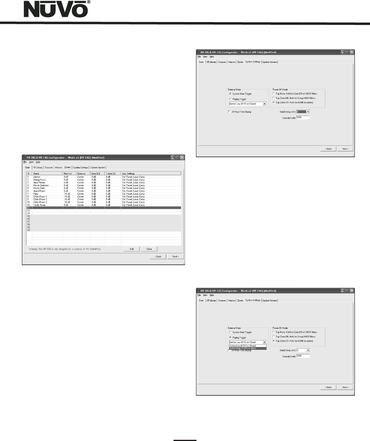
5. Zones (Fig. 24)
Up to 14 zones can be defined with the Essentia. Each zone
can be defined with unique properties.
You will notice that the zone tab contains 14 entries for zone
Control Pads. A full twelve zone system can accommodate a
total of 14 Control Pads by using the slave function in the
“Edit Zone Properties” window. A slave Control Pad is
homerun to the Allport, but automatically shares the same
functions and works in tandem with the main zone Control
Pad. Any number of Control Pads can operate on a single
zone.
19
Fig. 24
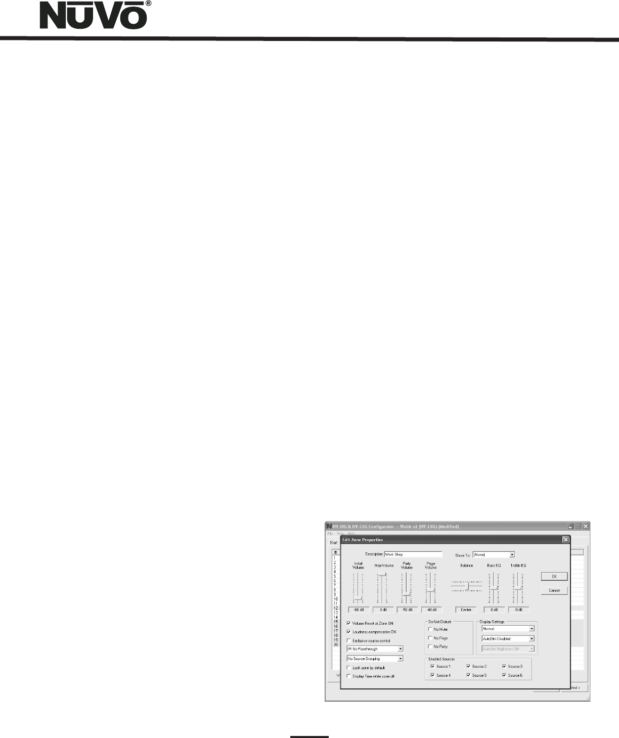
5.1 Edit Zone Properties (Fig. 25)
Max Volume:
Party Volume:
Page Volume:
Balance:
Double-clicking on a zone number opens the “Edit Zone
Properties” window. Specific properties defining that zone
are set here.
This allows the volume in a zone to be limited.
This can be done either to avoid damage to low-power
speakers or simply to prevent a certain room from being
turned up too high (e.g., a teenager's bedroom).
This controls the reset volume level for each
zone when the All On/Party Mode is initiated from any of the
Control Pads. The range is –78dB to –30dB.
If you are using the paging feature of the
Essentia System, you can also set the specific volume level
of the page zone by zone, by using this volume control. The
range is –78dB to –30dB, with a default at –40dB.
The level of output to the left and right speakers is
adjusted here. The default is center, but depending on the
location of the speakers and the optimal listening area of
the room, it may be advantageous to adjust the balance to
either the left or the right. Keep in mind that this setting
can be made and adjusted from within the Zone Setup menu
at the Control Pads.
Bass and Treble:
Volume Reset at Zone ON:
Loudness Compensation ON:
Exclusive Source Control:
IR Pass-through:
IR Disabled
IR No Pass-through
Both bass and treble can be adjusted
individually on a zone by zone basis. The EQ sweep is -18dB
to +18dB. Keep in mind that these levels can also be set at
the zone Setup menu at the Control Pads with music playing.
This will be covered later in the Control Pad menus.
A zone-specific feature is the
ability to have a zone automatically reset to a low volume
level when the zone is turned on. This check box initiates
that feature and is tied to the Zone Reset Volume level set
above it. If this box is not checked, the zone will turn on at
the last volume level.
This box defaults to checked and
enables an automatic bass and treble boost when the zone is
at a low listening level. This EQ gradually flattens out as the
zone volume is increased. Deselecting the box turns this
function off.
Checking this box gives this zone
exclusive “do not disturb” control of any chosen source.
Other zones will have the ability to listen to that source, but
they will not have any specific function control.
Each zone Control Pad has an IR receiver
for wireless remote control. By its nature, IR is susceptible
to external interference. To account for this, there is specific
IR pass-through settings for each Control Pad.
turns off the IR receiver completely and eliminates any
possibility of a competing light source. This is useful in an
environment in which the Control Pad receiver is competing
with overwhelming sunlight. This will prevent IR
communication throughout the system and therefore, it is
better to eliminate that light source.
prevents third-party remote control commands from being
accepted, but still allows the NuVo NV-GRC1 remote control
to operate the system. In some zones this is necessary when
a third-party remote is often used to control a non–NuVo
System source such as a TV. This would eliminate that remote
control's commands from being received by the Control Pad
and passed through to the source equipment.
20
Source Grouping:
Lock Zone By Default:
Display Time While Zone Off:
Do-Not-Disturb:
No Mute:
No Page:
No Party:
This allows for one zone to automatically
listen to the same source as all other zones in the group.
This is a very useful feature for a large open area where it is
not practical for more than one source to be playing at one
time. The advantage of the zone group is that each Control
Pad within the group has the ability to turn on or off, mute,
and control volume independently. This drop-down menu
allows any zone to be assigned to a group, or as an
individual zone with no group affiliation. Up to four distinct
groups can be created.
This check box turns on a function that
automatically prevents any functionality from the zone until
the assigned security code is entered. Primarily, the
function prevents an outside zone from being turned on
except when the homeowner really wants to listen to it.
Checking this box causes the
Control Pad to automatically display the current time when
the zone is turned off. In normal operation the time is always
displayed in the upper right corner. The time is
automatically set according to the computer when the
configuration is downloaded to the Essentia.
This Section is used to lock out system-
wide commands from a specific zone.
The Essentia System has a small accessory
called the Mi1 which is designed to mute all zones when
the phone or doorbell rings. This is defeated on a zone by
zone basis by checking the No Mute box. Installation of
the Mi1 is covered in the Accessory section of this manual.
The Essentia System is capable of paging
through audio source input 6. This involves a phone
system that has a paging audio output and a means to
provide a voltage trigger. This is controlled using the
Security tab to set the voltage trigger and utilizing the
Mute Input, see Mute Input page, 31. This will be covered
in the next tab.
Master and Party refer to the ability to turn all
zones on simultaneously. In some zones you may not want
this function.
Enabled Zone Sources:
Display Settings:
Dimmest, Dim, Not So Bright, Normal, Bright, Brighter,
Brightest
AutoDim Disabled, 15 Sec
up to 1 Hour AutoDim level.
AutoDim Brightness Off
Using AutoDim Low, AutoDim
Brightness Medium, AutomDim Brightness High
Slave To:
These allow individual sources to be
turned off for specific zones. A source that is turned off will
not display in that zone. This is particularly useful in
preventing child access to a source dedicated to adult
listening.
The overall brightness and AutoDim
feature for each Control Pad are set using these drop-down
menus. The first menu is the display brightness. The choices
are
. The second menu sets the duration for the
AutoDim feature. These range from
. The next menu sets a specific
removes all display and
backlighting. Brightness
or reduces
the level of brightness, but does not make the Control Pad
completely dark.
This drop-down menu is used to assign additional
“slave” Control Pads to a zone. Up to 14 Control Pads can be
used in an installation. The EZ Port hub is equipped with 14
RJ45 ports to accommodate all the system's Control Pads.
This is a useful feature for large rooms where more than one
Control Pad is desired. If slave Control Pads are used, we
suggest that you disable the IR pass-through on those to
prevent cross-communication. The Slave To function can
also be used to tie two or more zones together under the
control of a single Control Pad.
Fig. 25
21
Fig. 26
6. System Settings
This tab is used to define the way in which the External Mute
input functions, for setting the zone lockout security code,
to set the clock for 24 hour display and if necessary to set a
serial communication display.
6.1 External Mute: System Mute Trigger (Fig. 27)
The Essentia System has an accessory, the NV-MI1 Mute
Interface, which is designed to mute any music playing
through the system when a doorbell or phone rings, see MI1
Mute Interface, pg. 31. When setting the System Mute
Trigger, set the mute input to respond to the contact closure
provided by the MI1.
5.2 Zones (updated) (Fig. 26)
When the desired properties for each zone are set, click on
OK. This will return you to the Zones tab. There you will see
an updated list of the zones by the number they are
assigned, as well as the specific parameters defined in the
Zone Edit window.
Double-clicking on the zones will reopen the edit window,
where any of the definition properties can be modified.
Fig. 27
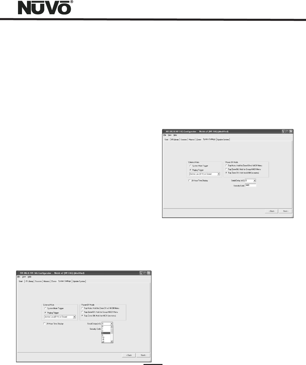
6.2 External Mute: Paging Trigger (Fig. 28)
The Essentia System has a built-in solution for whole-house
paging typically through a phone system. The Paging Trigger
setting causes the system to mute across all the zones, and
in turn, amplifies the page across all zones. Each Zone Edit
utility in the Configurator Software or the menu at each
Control Pad offers the capability of setting the page volume
in each zone.
Fig. 28
22
Fig. 29
6.3 24 Hour Time Display and Power Off Mode
24 Hour Time Display:
Power Off Mode:
Tap Mute/Hold for Zone-Off w/ All-Off Menu:
Tap Zone-Off/Hold for Group/All-Off Menu:
Tap Zone-Off/Hold for All-Off (no menu):
6.4 Serial Delay (Fig. 29)
By checking the 24 Hour Time Display
box, the system will automatically go to a 24 hour clock on
each of the zone Control Pads.
The Essentia Configurator allows the option
for three power off modes.
This mode
causes a temporary zone mute when the Control Pad power
button is tapped. When it is held for three seconds, a menu
will appear with the option to turn the zone off or turn all the
zones off.
In this mode a
single tap of the power button turns the zone off and holding
the power button causes a second menu that gives the
option to turn off that zone’s group or turn all the zones off.
This is the default
choice. In this mode, a tap turns the zone off and holding the
power button turns all the zones off.
This drop down menu provides a choice of delays measured
in milliseconds. This is only necessary when you are using
the RS232 communication for third party control of the
Essentia System. This utility slows the rate at which
information is delivered to the home automation system
from the Essentia. This is sometimes necessary to allow the
home automation’s processor time to buffer the incoming
information.
6.5 Security Code (Fig. 30)
A feature with the zone setup of the Essentia System is
the ability to lock the zone. This can be done as a default
that will require a four-digit security code to unlock the
zone Control Pad when the zone is turned on, or it can be
done as a temporary setting from the Control Pad menu to
lock the zone on its current listening choice. In either
scenario, the security code must be set to unlock the
zone. The security code can be any four digits or left at
the default 5555.
Fig. 30
7. Update System (Fig. 31)
Control Pad Firmware Update (Fig. 31a)
The finished configuration is now ready to be downloaded
to the Essentia amplifier. While downloading, a progress
box will show download progress. Once complete, the
configuration is permanently stored in flash memory.
Configurations can always be retrieved and edited at a
future date.
When first plugged in and addressed, the Control Pads
will poll the main unit for the correct firmware version. If
they are at a lesser version number an upgrade notice will
appear on the display. It is important to allow this process
to complete. When the Control Pad is finished upgrading
itself it will turn off. At that point, it is ready for zone
control use.
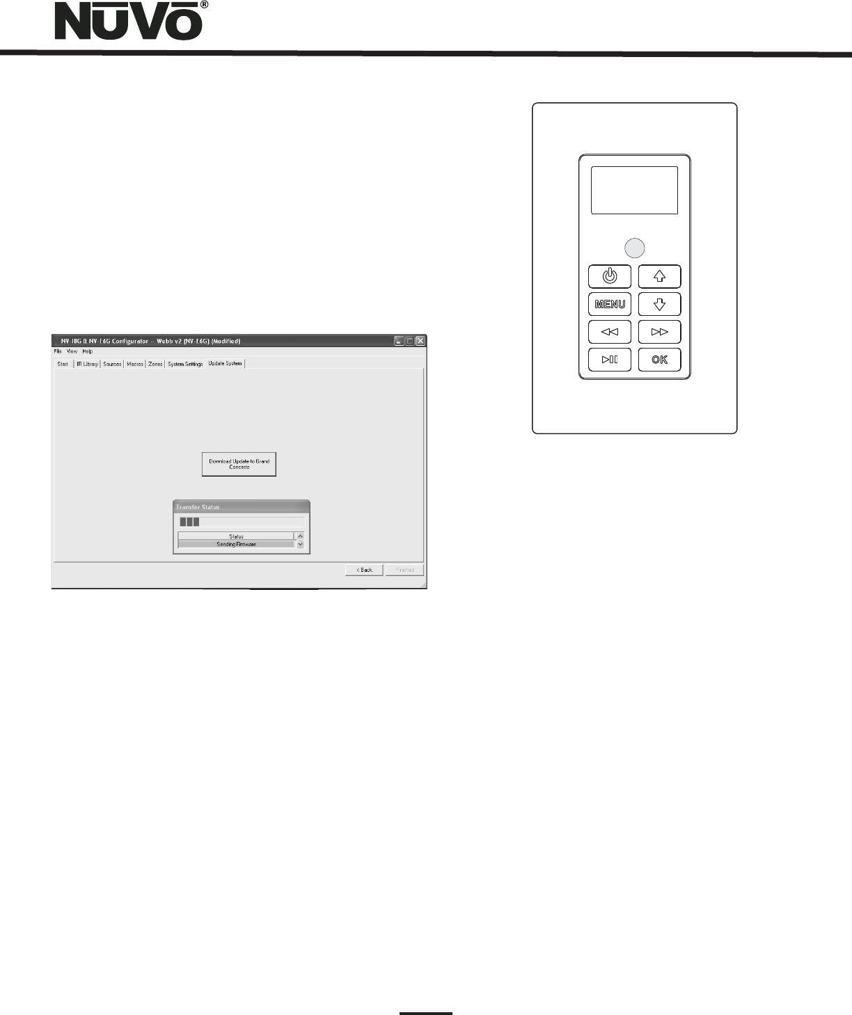
Fig. 31
Fig. 31a
23
Firmware Upgrade..
Please Wait
Please note that if multiple Control Pads are plugged in
during the update process they will update themselves one at
a time in succession beginning with zone one. Wait for the
entire process to complete until the last zone turns off.
DO NOT unplug the Control Pads or cycle power during this
process.
24
X. Control Pad Setup
Factory-new Installation
Essentia V. X.XX
Zone Selection
Zone 1, Zone 2, Zone 14
OK
Reprogramming the Zone Address
Setup Advanced Settings
Zone Number
None
The system should be programmed with the Configurator
prior to setting up the Control Pads for the first time. The
Essentia amplifier should be placed in its permanent
location, plugged in, and turned on. When a Display Pad is
plugged in for the first time, the following sequence will
occur:
1. When first plugged in, where X
refers to the current firmware version number
loaded in the Essentia main amplifier unit.
2. Press the Power Button to turn the Control Pad on.
The display will flash the Essentia Version number
screen and immediately go to . If you
have loaded a Configuration into the main unit,
once in Zone Selection mode, all the configured
zone names will appear starting with the first. If you
are setting the system directly out of the box, it will
list generic etc., up to .
Setting the appropriate zone address is simply done
by using the arrow buttons to scroll up or down to
the appropriate zone and pressing the button.
The Control Pad will flash the version-number
screen one more time and immediately turn off.
When powered on, the addressed Control Pad will
then go to the first established source.
At this point, the zone may be operated by the parameters
set in the Configuration. Zone settings may be modified
using the MENU key.
This procedure allows an addressed Control Pad to be moved
to a new location. Within the main menu of each zone, go to
. Within the Setup options, scroll to
and to . All the used addresses will be grayed
out. That specific zone will have a check mark displayed. Any
available addresses will be accessible. Scrolling to will
erase the current address.
3.
XI. Using the Control Pad's MENU Button
MAIN MENU
Favorites, Sources,
Advanced Zone Control Setup,
Menu gives access to specific music selection and control for
each source, as well as zone and system setting capability.
When the MENU button is pushed, the display goes to a
four-line screen labeled Main Menu.
: There are four Main Menu items that are
consistent to all source selections and pertain to general
system and zone control. They are
and Fig. 32.
Fig. 32
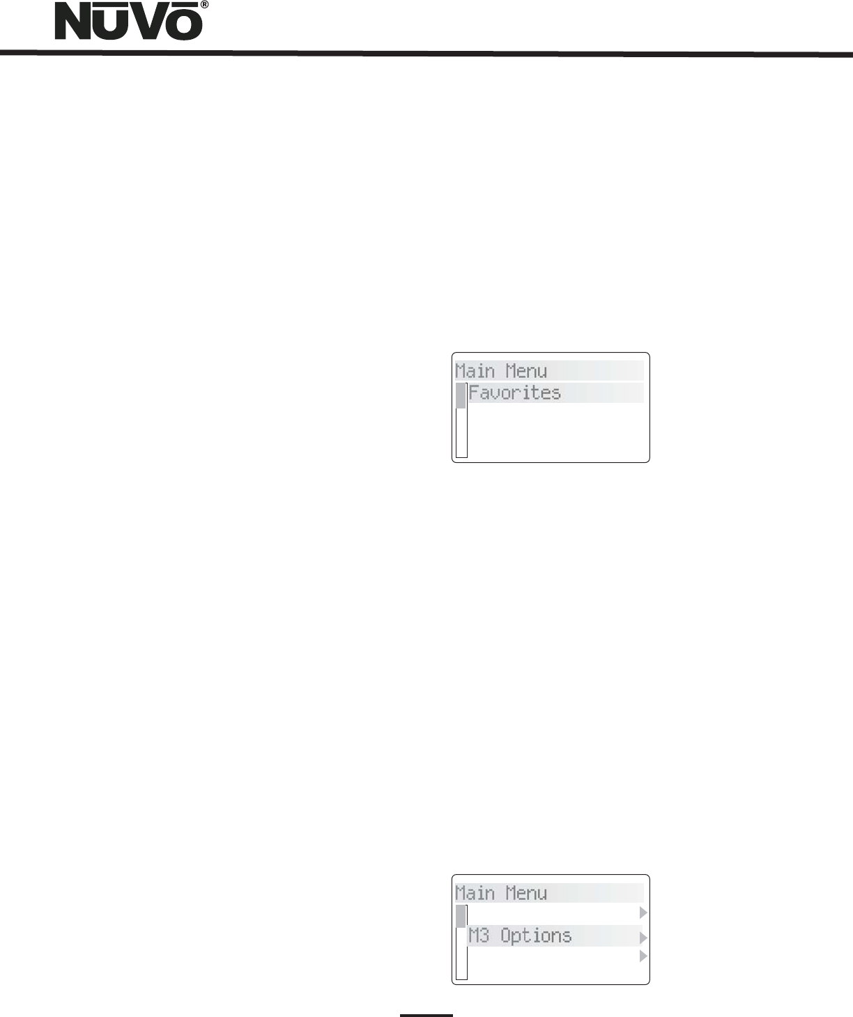
Favorites:
M3 Options or iPod Options
Options
Top-line favorites are global. Favorites or play
lists set up within Windows Media Player and synced with
the NuVo M3 Server or within an iPod can be added to the
Favorites list. Potential members of this list can also include
station presets for the NuVo T2G or other sources such as
satellite or cable. When T2G or IR Macro Presets are
assigned, the first twenty are placed in the Favorites menu.
Assigning playlists within the M3 or iPod to global favorites
is done in the menu, Fig. 33. This
menu item automatically resides with the M3 or iPod as a
source choice. Once in the menu, the choices are
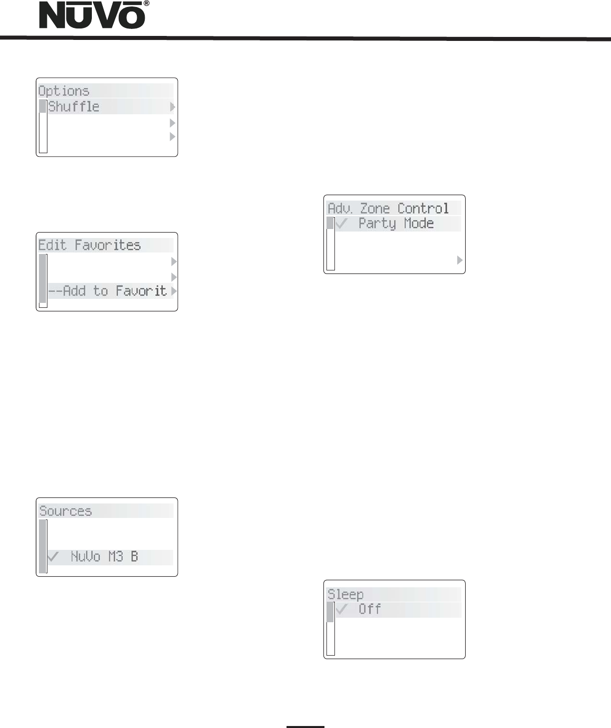
Shuffle, Repeat, Juke Box Mode and Edit Favorites, Fig. 34.
When Edit Favorites is chosen, Add to Favorites will allow
you to add any playlists from the hard drive of either the M3
or iPod, Fig. 35. When the desired choice is highlighted,
pressing the OK button completes the task.
Fig. 33
Main Menu
Favorites
Sources
Adv. Zone Control
Main Menu
Play All
M3 Options
Adv. Zone Control
Options
Shuffle
Repeat
Juke Box Mode
Edit Favorites
Sources
Rock
Dinner Party
--Add to Favorit
Satellite
NuVo M3 A
NuVo M3 B
Fig. 34
Fig. 36
Fig. 35
Fig. 37
Fig. 38
Sources: This offers quick access to the six sources defined
in the system. Third-party sources can be defined with a
source name in the Essentia Configurator Software, or they
are labeled by the system as a generic source number. The
NuVoNet sources have a predefined system name unless you
choose to assign a customized name in the Configurator
Software, Fig. 36.
Advanced Zone Control: Advanced Zone Control is designed
for user access to temporary zone settings. Each of the zone
parameters set in advanced zone control automatically reset
when an All Off command is issued from a Control Pad, Fig.
37.
Party Mode:
Do-Not-Disturb:
Sleep Mode:
This setting is turned on and off with the
OK button. When selected all the configured zones in
the system will turn on and that Control Pad becomes
the Host for the entire house. This function is defeated
in an individual zone by initiating a function on that
zone’s Control Pad.
This sets a temporary source lock on a
chosen source within that zone. This selection is also
turned on and off by pressing the OK button.
The Sleep Mode, when set, allows music to
play in that Control Pad’s zone for a specified amount of
time, Fig. 38. Once the time selection is made, the
system will gradually ramp down in volume and the zone
will turn itself off at the end of the selected time.
25
Adv. Zone Control
Sleep
Party Mode
Do-Not-Distrub
Sleep
Off
15 Minutes
30 Minutes
26
Lock Zone:
Lock Zone & Off:
This temporarily locks the zone on the
current source selection. It requires a four digit security
code that must be set in the Settings Tab of the
Configurator Software. The security code is entered on
the Control Pad by using the up and down arrows to
scroll to the first number and pressing OK. The display
will then highlight the next number. Using the process
described above, set the second, third and fourth
numbers. Once the fourth number is set, the zone will
remain locked until the security code is entered to
unlock it, Fig. 39.
This temporary lock works very much
like Lock Zone, but is used to turn the zone off and
requires the security code to turn the zone back on.
Fig. 39
Fig. 40
Setup: The Setup menu is for specific system setup. It
consists of several subset menus . These are defined
in the next section.
, Fig. 40
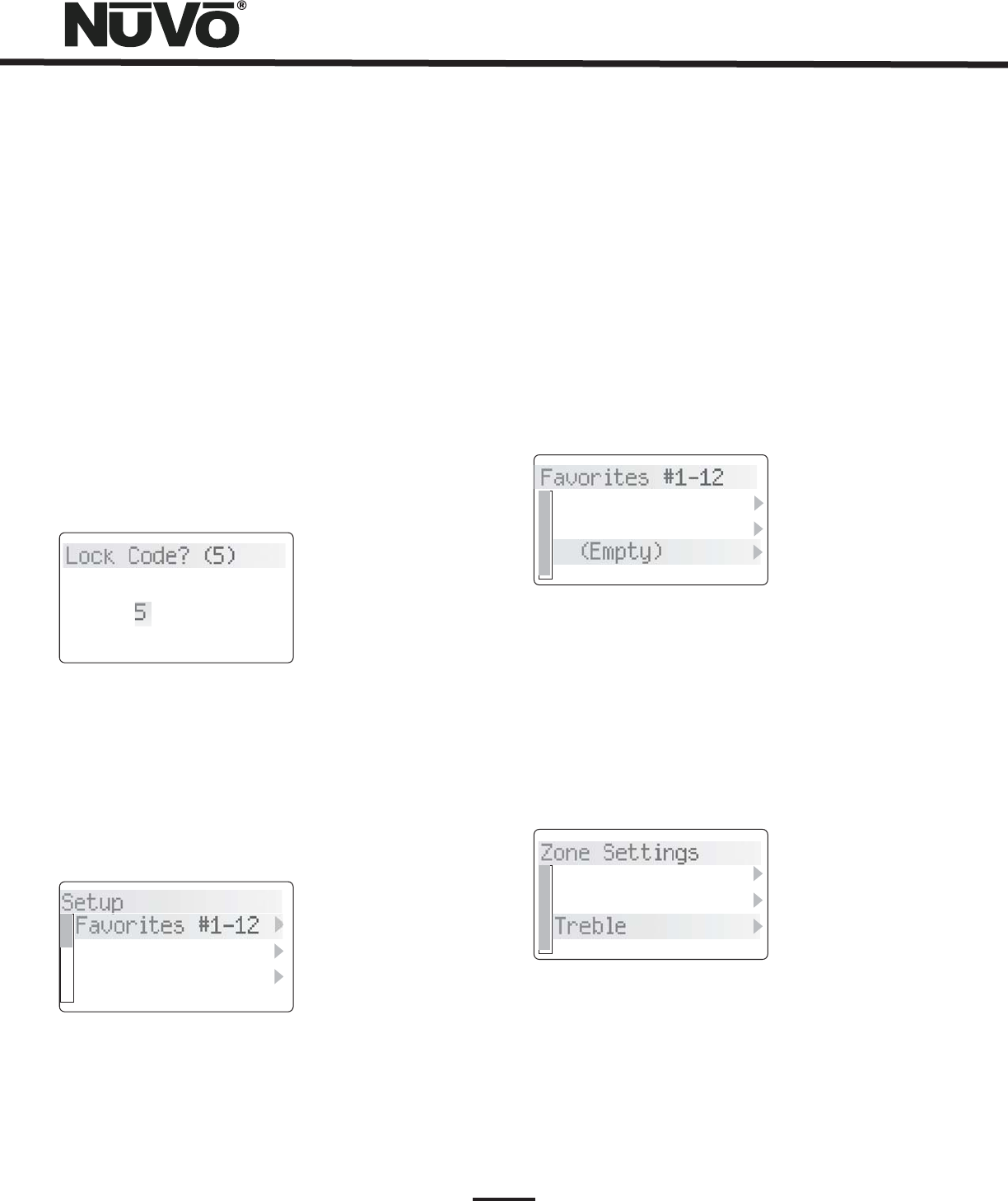
Favorites #1-12: Twelve global favorites can be defined
for easy access from within the Main Menu, or from the
twelve numeric favorites from the Essentia
remote control. Any favorites, which include M3 and
iPod play lists, tuner presets and specific disc selections
can be selected in the Favorites setup and automatically
added to the global list. The Essentia Remote
Control has a 12-button numeric Control Pad that
provides
direct access to the 12 assigned favorites. When a
favorite is selected, the zone will automatically go to the
appropriate source and music selection, Fig. 41.
Fig. 41
Fig. 42
Zone Settings: This selection contains several zone specific
controls, Fig. 42. (Note that Advanced is grayed out and is
preceded by an asterisk. This is an installer specific level
that is accessed by holding the OK button for six seconds. )
Lock Code? (5)
3485
Setup
Favorites #1-12
Zone Settings
*Souce Settings
Favorites #1-12
Zone Settings
Rock
Jazz
(Empty)
Balance
Bass
Treble
27
This controls the level of audio going to the left
and right speakers. In some cases, when the listening
area is not absolutely centered between the speakers, it
is useful to adjust the center listening point left or
right. This menu option gives the ability to adjust the
sound left or right up to 18 steps in either direction.
This adjusts the frequency level from 100Hz and
below. The default is flat, and the range is –18dB to
+18dB.
This adjustment works within the same
parameters as the bass and adjusts the frequency level
from 10kHz and up.
Loudness can be simply turned
on or off by pressing the OK button.
There are several default settings
available in this menu. is turned on or off
by pressing the OK button and controls whether the
zone turns on at its previous volume level, or to a preset
level, Fig. 43. If checked, the volume when the zone is
turned on reverts to the level set in the next menu item,
. Choosing to set at the current listening
level, or selecting the default –60 dB level, controls this
level. is an overall zone volume limit
and is set in the same manner as Initial Volume.
controls the level at which a page is amplified in
each zone, and sets the initial volume
level when the party or all-on function is initiated.
Balance:
Bass:
Treble:
Loudness Compensation:
Volume Settings:
Volume Reset
Initial Volume
Maximum Volume
Page
Volume
Party Volume
Fig. 43
Fig. 44
Fig. 45
Advanced Zone Settings: These are parameters for each zone.
They can be easily established in the Configurator Software
or here at each of the zone Control Pads, Fig 44.
Source Lockout:
Exclusive Src. Ctl.:
Group:
Default DND:
Any source selected in this menu will be
locked from access within that zone.
This sets a default that automatically
grabs control of any source chosen within this zone.
Other zones will be able to listen, but they will have no
specific source control. This is a permanent zone setting.
Source Group is a great NuVo feature for large,
open-floor living spaces. In this menu option, any zone
can be set to share source among a group of zones to
prevent the likelihood of having more than one source
playing in the same open space. The advantage to Source
Group is that each zone area maintains individual on/off
and volume capability.
This prevents the global functions of all-
on or party and whole-house page from a Control Pad's
specific zone, Fig. 45.
Default Zone Locked: A locked zone prevents anyone
from turning the zone on and accessing music without
first entering the security code.
Initial Volume
Set (current volu
Reset (-60 dB)
Adv. Zone Settings
Source Lockout
Exclusive Src. C...
Group
Default DND
No Mute
No Page
No Party
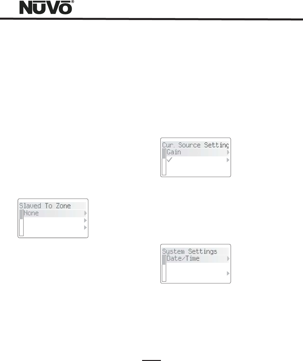
Remote Controls:
All
Remotes Enabled
NuVo Remote Only
All
Remotes Disabled
Slaved to Zone:
These settings affect the way the
Control Pad receives commands from a handheld
wireless remote. The NV-GRC1 is the system remote that
comes with the Essentia. It allows the same level of
control as the Control Pad. At the default setting,
, this remote and any third-party IR
remote will be received by the zone's Control Pad. In
some instances, you may not want a third-party remote
command to be received by the Control Pad. In this case,
you would choose . If the zone is in an
area that is flooded with sunlight or receives
interference from plasma displays, the best choice is
.
A feature of Essentia is the ability to
slave zones together. This is most useful for controlling
a zone with more than one Control Pad, or the converse,
which is controlling more than one zone with one
Control Pad. Simply scroll to the zone you wish to slave
to and select it from the list, Fig. 46 .
Zone Number:
Slaved Zone
Diagnostic Self Test:
Each zone must be assigned a number or
specific zone address. This is done by scrolling to the
desired zone and selecting it. All used zone addresses
will be grayed out. If you have defined zones in the
Configurator Software, the actual zone names assigned
in the Zone tab of the software will appear in the list.
The zone list appears just as it does in the previous
menu. Scrolling to a different zone name
and pressing OK will set a new zone address, or
selecting NONE erases the zone address.
This performs a short display
parameter test when selected.
Fig. 46
Fig. 47
Source Settings:
Gain:
NuVoNet Source:
Two choices reside in this menu regarding
the currently playing, Fig. 47.
This lets you increase the audio input levels from
the sources coming into the Essentia. This is not
necessary for the NuVoNet components, but if you use a
satellite or cable set-top box as an audio source for the
system, you will find that the audio level is inherently
softer and will benefit by the gain setting. The default is
0dB, with a range up to 18.75dB.
If you uncheck this selection, that
source will not be polled by NuVoNet and will only be IR
controllable.
source
System Settings: This menu option controls system-wide
settings, Fig 48.
Fig. 48
28
Slaved To Zone
Cur. Source Setting
System Settings
None
Kitchen
Dining Room
Gain
NuVoNet Sourc.
Date/Time
24 Hour Time Dis..
Power-Off Mode
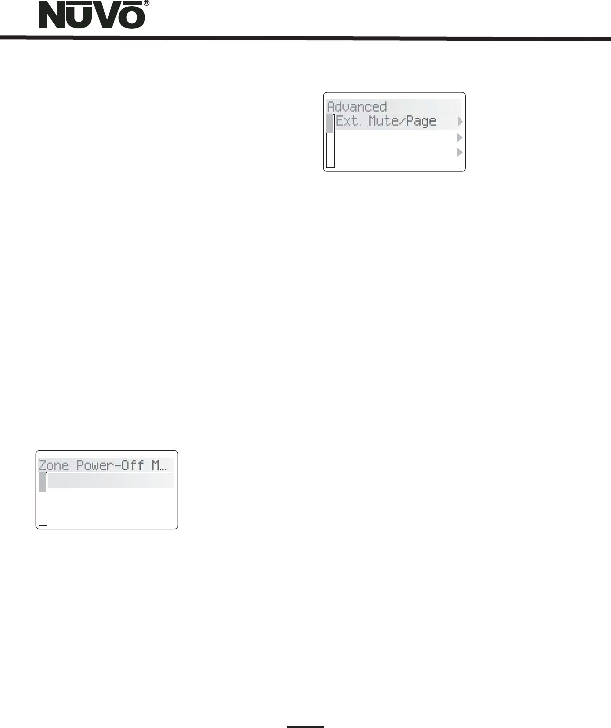
29
Fig. 49
Fig. 50
Date/Time:
Year, Month, Day,
Hour, Minute
24 Hour Time Display:
Power Off Mode:
Mute/Off/ w/ Menu
Off/All-Off Menu:
Off/All-Off:
The Essentia has an internal clock that
allows each Control Pad to display the current time.
Within this menu you can easily set
and .
This is a simple on/off. When
this menu item is turned on, the clock display on the
Control Pads switches to 24 hour display.
This refers to three choices for the way
in which each zone turns on and off. They involve a
single tap of the power button and a hold function, Fig.
49 .
is the first choice. This selection
means that a tap of the power button mutes the zone,
but does not turn it off. The hold function brings up a
second menu that requests All Off, yes or no. No turns
off just that zone, yes turns off all zones.
In this mode, a tap of the power
button turns the zone off and a second menu appears
that gives to choice to turn off that zones group (if it is
assigned to a source group) or to turn all zones off.
The is a tap of the power button to turn the
zone off and a hold of the power button to turn all zones
off.
Advanced: Within the System settings menu are advanced
functions intended for installers. The item is preceded by an
asterisk and grayed which requires that the OK button is
held for six seconds before the advanced functions are
accessible, Fig. 50.
External Mute/Page:
Paging Mode
Active
Low (Closed)
Serial Delay:
Sources:
Reset System:
Yes
The EXT. MUTE input on the back
panel of the Essentia has a dual function. In its default
setting, it is designed for the Mute Interface, NV-MI1
(see NV-MI1 Mute Interface Adaptor page, 31). It can
also be configured for use with a paging phone system
to enable whole-house paging. This requires a phone
system that provides an audio output for paging that is
plugged into source input 6 on the Essentia (note that
this feature eliminates the use of Source 6 as an audio
source for the system). To use the Page function, you
must select . There are two types of voltage
triggers associated with the Page function. If the phone
system you are using sends a voltage to trigger paging,
selecting Paging Mode sets the mute input to react and
mute all zones. If it triggers by creating a closure
(dropping down to 0 voltage), you need to select
.
This function is only used in conjunction
with third party home automation systems. This function
sets a delay in milliseconds between each of the
function commands being streamed through the
Essentia RS232 port. This allows a slower home
automation processor to buffer multiple commands
from the Essentia System.
This Allows unused source inputs to be turned
off so they do not show up when you scroll through the
sources at the Control Pads.
This is a shortcut for resetting the zone
addresses assigned to each Control Pad. Within the
menu selection, restores all Control Pads plugged
into the system to the factory default.
Zone Power-Off M...
Tap/Hold Action
Mute/Off w/Menu
Off/All-Off Menu
Advanced
Ext. Mute/Page
Serial Delay
Sources
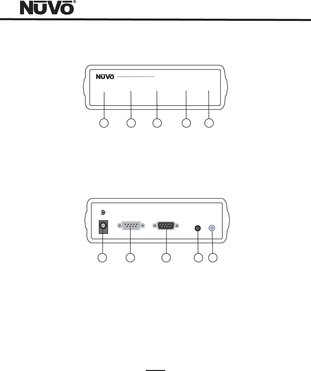
30
XII. Essentia Accessories
The NV-I8DLS IR Learning Station Interface
Concerto Learning Station
Model NV-I8DLS
PASSTHRU READY IR SENSOR TEST ACTIVE POWER
12345
1. PASSTHRU:
2. READY:
3. IR SENSOR:
4. TEST ACTIVE:
5. POWER:
This LED (light emitting diode) remains lit when the Interface box is actively passing IR information through the
system.
When you are inputting IR codes into the Configurator using the Interface box, this LED will light when the system is
ready to learn a new code.
This is the IR receiver used when capturing codes for new source equipment.
When you are testing an IR code, this LED lights momentarily when the code is firing.
This LED remains lit when the interface box is plugged into an AC electrical outlet.
+-
POWER
12VDC/0.4A
CONNECT TO
PC
CONNECT TO
CONCERTO D
IR
EMITTER
IR
BLASTER
12 345
1. AC Power:
2. CONNECT TO PC:
3. CONNECT TO GRAND CONCERTO D:
4. IR EMITTER:
5. IR BLASTER:
A standard 12-volt power supply is included in the Learning Station Package. This will supply the necessary AC power
for IR learning and testing.
Using one of the supplied RS232 cables, connect from the RS232 port on your computer to this input on the
Learning Station Interface.
Using the second RS232 cable, connect the Learning Station Interface to the Essentia
amplifier's RS232 port.
An IR mouse emitter is supplied with the Learning Station package. A feature of the Configurator Software is the
ability to test each new code that is learned by the interface. The software will send the IR command to the source equipment
via the IR emitter so you can have visual reference that the source equipment responded appropriately to the command.
Another built-in IR test method is the use of the blaster. The test process is the same in the Configuration
program, but the IR Blaster allows you to point the back of the Interface box toward the source equipment IR receiver. This fires
the IR command and eliminates the need for the mouse emitter.

31
Capturing IR codes using the IR Learning Station Interface
Note that the
remote control should be held 8 to 10 inches from the Interface when learning.
The IR Learning Station is a universal device for Essentia, Concerto, and Grand Concerto use.
The Essentia Configurator Software is designed to store IR codes for audio equipment in an IR Library. When the codes are learned
for a given piece of equipment, they are held in the library under that equipment's manufacturer name and model number. Once
learned, any of the equipment in the library can be imported into a new Configuration.
To learn new equipment codes, the Learning Station Interface box must be connected to your computer at the RS232 port. Connect
the male end of the RS232 cable to the back of the Interface box into the “CONNECT TO PC” input. At this point, it is not necessary
to have the Interface box connected to the Essentia amplifier.
When setting up a new source, each type of equipment has a pre-selected set of functions. By double-clicking on a function or
clicking on the “Record” button in the software, you will open the record window. You will see the “READY” LED light on the
interface box. Aim the source's remote control at the “IR SENSOR” on the Interface and press the desired function button on the
remote. The IR learning window in the Configurator Software will indicate the code has been successfully learned.
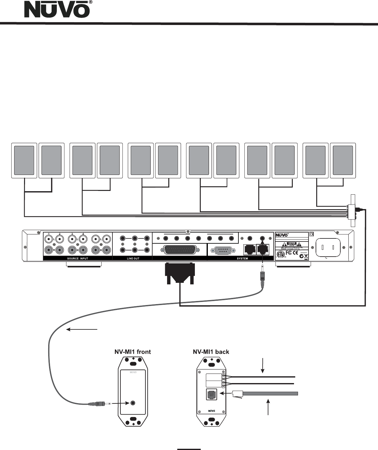
MUTE INTERFACE
ADAPTER
NV-MI1
CONNECT TO
MUTE INPUT
A
B
A
B
DOORBELL 1
DOORBELL 2
Connect to Telephone RJ11
Line 1: Pins 3,4 Line 2: Pins 2,5
Mute Interface Module
Model NV-MI1
The NuVo NV-MI1 Mute Interface Module is designed to automatically mute any audio playing through
the System’s speakers when the telephone or doorbell rings.
The MI1 connects to the NuVo amplifier using a standard
mono patch cable with a mini-plug on each end. Plug one
end into the MUTE input on the back of the amplifier
and the other end into the input on the front of the MI1.
The back of the MI1 will accept up to two AC or
DC voltages from two different doorbell chimes.
This connection is done with two conductor wires
from the terminals on the doorbell chime to the
Doorbell A or Doorbell B inputs on the back of the
MI1. Polarity is not important for this connection.
Up to two phone lines can be brought into the
RJ11 connection on the back of the MI1. The
voltage from the phone ringer will trigger the
NuVo System to mute.
32
NV-MI1 Mute Interface Adaptor (Fig. 51)
The Mute Interface is used in conjunction with System Mute input on the back of the Essentia amplifier. It acts as relay for a
voltage from up to two phone lines and two doorbell transformers. When a voltage is presented to the MI1, it sends a contact
closure to the Essentia System, which causes the system to mute momentarily. This is useful in allowing the telephone or doorbell
to be heard when audio is playing in any of the zones.
56 FIXED VAR
ZONE
1
TRIG
ZONE
2
STATUS
NuVoNet
RS232
1SUM
ALLPORT CONNECTION
IR OUTPUTS
23456 LINK
MUTE
MADE IN CHINA
100~240V 50~60Hz 130W
1807
N1839
www.nuvotechnologies.com
MODEL NV-E6GM
SIX SOURCE SIX ZONE
AUDIO DISTRIBUTION SYSTEM
3033118
NuVo Technologies LLC Hebron, Kentucky USA•
CONFORMS TO UL
STD.60065 CERTIFIED
TO CAN/CSA STD.
C22.2 No.60065:03
RoHS
CCC
CCCCCC
CCCCCC
CCCCCC
CCCCCC
CCCCCC
CCCCCC
CCCCCC
CCCCCC
CCCCCC
CCCCCC
CCCCCC
CCCCCC
CCCCCC
CCCCCC
CCCCCC
Fig. 51
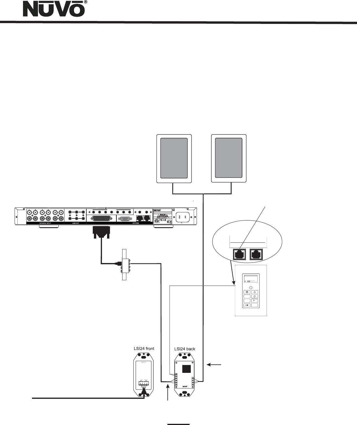
Essentia Control Pad
LOCAL SOURCE
SWITCH
NV-LSI24
CONNECT TO
AMPLIFIER
RLY+
RLY-
L-
L+
R-
R+
To Amplifier
To Keypad
To Speakers
L-
L+
R-
R+
Model NV-LSI24
Mute Interface Module
The connection from the LSI24 is made through the
Accessory RJ45 port on the back of the Control Pad
terminated with standard 568A. The connection at
the LSI24 requires the use of the Brown lead for
positive and Brown Stripe for negative.
Accessory NuVoNet
33
NV-LSI24 Local Source Interrupt (Fig. 52)
The Local Source Interrupt enables an amplified local audio source to override the Essentia System and play through the local
zone’s in-wall speakers. The most common scenario for this is a television that would benefit from higher-quality speakers.
The back of the Essentia Control Pad has two Cat-5 inputs. One is labeled NuVoNet and is the Cat-5 that runs to the Allport at the
head end. The other is labeled NV-E6GLSA. This is intended to react to the LSI24 accessory. It requires an RJ45 connection at the
Control Pad end and the Brown and Brown Stripe pair as a voltage trigger. When the Control Pad is on, NuVo audio is allowed to
pass to the speakers in the zone. When the Control Pad is off, the amplified local source is passed to the speakers in the zone.
Note that the Local Source Interrupt is a passive non-amplified device. The signal sent to it must be amplified.
M3A
1:19 3:48
2 OF 2-Follow th...2 OF 2-Follow th...
drift-Edge of Tomdrift-Edge of Tom
MENU
OK
Two or four conductor speaker wire
from the LSI24 to the zone
speakers.
Speaker input from Essentia
Amplified signal from the local zone source
56 FIXED VAR
ZONE
1
TRIG
ZONE
2
STATUS
NuVoNet
RS232
1SUM
ALLPORT CONNECTION
IR OUTPUTS
23456 LINK
MUTE
MADE IN CHINA
100~240V 50~60Hz 130W
1807
N1839
www.nuvotechnologies.com
MODEL NV-E6GM
SIXSOURCE SIX ZONE
AUDIODISTRIBUTION SYSTEM
3033118
NuVoTechnologies LLC Hebron, Kentucky USA•
CONFORMSTO UL
STD.60065CERTIFIED
TOCAN/CSA STD.
C22.2No.60065:03
RoHS
CCC
CCCCCC
CCCCCC
CCCCCC
CCCCCC
CCCCCC
CCCCCC
CCCCCC
CCCCCC
CCCCCC
CCCCCC
CCCCCC
CCCCCC
CCCCCC
CCCCCC
CCCCCC
Fig. 52
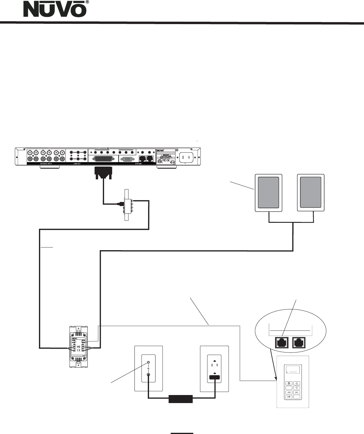
INPUT
POWER
A two conductor wire is used as a voltage trigger
from the LSA40 the NuVo zone Control Pad. When the
zone is turned on this allows to NuVo system audio to
pass to the zone speakers. When the zone is turned
off the internal amplifier of the LSA40 is
automatically engaged.
LSA40 Back
LSA40 Front
50 Watt AC
power adapter
supplied with
the LSA40S
AC Power Source
Any stereo line level source
signal can be amplified through
the local source speakers using
the LSA40.
Any NuVo System zone output
can be wired to the LSA40 Local
Source Amplifier.
NuVo System zone
speakers.
++
--
LL
LL
RR
RR
++
++
--
--
MODEL:NV-LSA40
LOCAL SOURCE AMPLIFIER
28VDC
TO
KEYPAD
1.5A
TO AMPLIFIER
TO SPEAKER
WIRE STRIP 5/16” (8MM)
Designed In USA
Made In China
NuVoTechnologies LLC Cincinnati, Ohio USA
www.nuvotechnologies.com
NV-LSA40
Local Source Amplifier
NV-LSA40 Local Source Amplifier (Fig. 53)
The LSA40 is a 40 watt stereo amplifier designed to fit neatly in a single gang box or ring. It’s active state provides a ready input
for any line level audio signal. When connected to the Essentia Control Pad, the Essentia speaker output and the LSA40 share a
common pair of speakers in a zone. The LSA40’s internal A/B switch allows NuVo audio when the zone Control Pad is turned on and
local audio through the LSA40, when the zone Control Pad is turned off.
Accessory NuVoNet
The connection from the LSA40 is made
through the Accessory RJ45 port on the
back of the Control Pad terminated with
standard 568A. The connection at the
LSA40 requires the use of the Brown lead
for positive and Brown Stripe for
negative.
34
M3A
1:19 3:48
2 OF 2-Follow th...2 OF 2-Follow th...
drift-Edge of Tomdrift-Edge of Tom
MENU
OK
56 FIXED VAR
ZONE
1
TRIG
ZONE
2
STATUS
NuVoNet
RS232
1SUM
ALLPORT CONNECTION
IR OUTPUTS
23456 LINK
MUTE
MADE IN CHINA
100~240V 50~60Hz 130W
1807
N1839
www.nuvotechnologies.com
MODEL NV-E6GM
SIXSOURCE SIX ZONE
AUDIODISTRIBUTION SYSTEM
3033118
NuVoTechnologies LLC Hebron, Kentucky USA•
CONFORMSTO UL
STD.60065CERTIFIED
TOCAN/CSA STD.
C22.2No.60065:03
RoHS
CCC
CCCCCC
CCCCCC
CCCCCC
CCCCCC
CCCCCC
CCCCCC
CCCCCC
CCCCCC
CCCCCC
CCCCCC
CCCCCC
CCCCCC
CCCCCC
CCCCCC
CCCCCC
Fig. 53

35
++
--
LL
LL
RR
RR
++
++
--
--
MODEL:NV-LSA40
LOCAL SOURCE AMPLIFIERLOCAL SOURCE AMPLIFIER
28VDC
28VDC
TO
KEYPAD
KEYPAD
1.5A
TO AMPLIFIER
TO AMPLIFIER
TO SPEAKER
TO SPEAKER
WIRE STRIP 5/16” (8MM)WIRE STRIP 5/16” (8MM)
Designed In USADesigned In USA
Made In ChinaMade In China
NuVo TechnologiesLLC Cincinnati, Ohio USANuVo Technologies LLC Cincinnati, Ohio USA
www.nuvotechnologies.comwww.nuvotechnologies.com
++
--
LL
LL
RR
RR
++
++
--
--
MODEL:NV-LSA40
LOCAL SOURCE AMPLIFIER
28VDC
28VDC
TO
KEYPAD
KEYPAD
1.5A
TO AMPLIFIER
TO AMPLIFIER
TO SPEAKER
TO SPEAKER
WIRE STRIP 5/16” (8MM)WIRE STRIP 5/16” (8MM)
Designed In USADesigned In USA
Made In ChinaMade In China
NuVo TechnologiesLLC Cincinnati, Ohio USANuVo Technologies LLC Cincinnati, Ohio USA
www.nuvotechnologies.com
++
--
LL
LL
RR
RR
++
++
--
--
MODEL:NV-LSA40
LOCAL SOURCE AMPLIFIER
28VDC
28VDC
TO
KEYPAD
KEYPAD
1.5A
TO AMPLIFIER
TO AMPLIFIER
TO SPEAKER
TO SPEAKER
WIRE STRIP 5/16” (8MM)WIRE STRIP 5/16” (8MM)
Designed In USADesigned In USA
Made In ChinaMade In China
NuVo TechnologiesLLC Cincinnati, Ohio USANuVo Technologies LLC Cincinnati, Ohio USA
www.nuvotechnologies.comwww.nuvotechnologies.com
LSA40 Back
LSA40 Back
LSA40 Back
LSA40 Back
+
-
+
-
MODEL:NV-LSA40PD-DC
LOCAL SOURCE AMPLIFIER
DESIGNED IN USA
28VDC 5A
ZONE 1
MADE IN CHINA
I
N
T
E
R
T
E
K
3033118
I
N
T
E
R
T
E
K
CM
ZONE 3
+
-
+
-
ZONE 2 ZONE 4
POWER
LSA40PD Front
LSA40PD
Back
200 Watt AC
power adapter
included with
the LSA40PD
AC Power Source
D
NV-LSA40PD Local Source Power Distribution Hub (Fig. 54)
The LSA40PD Power Distribution Hub provides a compact method for distributing the necessary power for up to four LSA40 Local
Source Amplifiers from one central location. The LSA40PD distributes the power over 16-AWG two conductor speaker wire to each
of up to four individual LSA40 amplifiers. Connecting the LSA40 to the NuVo Control Pad and speakers is identical to the individual
zone installation diagramed on page 33, Fig. 53. Note that if you are using the NV-LSA40PD the needed SKU for each zone
amplifier is the LSA40 which is the local source amplifier with no power supply.
CCC
CCCCCC
CCCCCC
CCCCCC
CCCCCC
CCCCCC
CCCCCC
CCCCCC
CCCCCC
CCCCCC
CCCCCC
CCCCCC
CCCCCC
CCCCCC
CCCCCC
CCCCCC
56 FIXED VAR
ZONE
1
TRIG
ZONE
2
STATUS
NuVoNet
RS232
1SUM
ALLPORT CONNECTION
IR OUTPUTS
23456 LINK
MUTE
MADE IN CHINA
100~240V 50~60Hz 130W
1807
N1839
www.nuvotechnologies.com
MODEL NV-E6GM
SIXSOURCE SIX ZONE
AUDIODISTRIBUTION SYSTEM
3033118
NuVoTechnologies LLC Hebron, Kentucky USA•
CONFORMSTO UL
STD.60065CERTIFIED
TOCAN/CSA STD.
C22.2No.60065:03
RoHS
M3A
1:19 3:48
2 OF 2-Follow th...
drift-Edge of Tom
MENU
OK
M3A
1:19 3:48
2 OF 2-Follow th...
drift-Edge of Tom
MENU
OK
M3A
1:19 3:48
2 OF 2-Follow th...
drift-Edge of Tom
MENU
OK
M3A
1:19 3:48
2 OF 2-Follow th...
drift-Edge of Tom
MENU
OK
Fig. 54
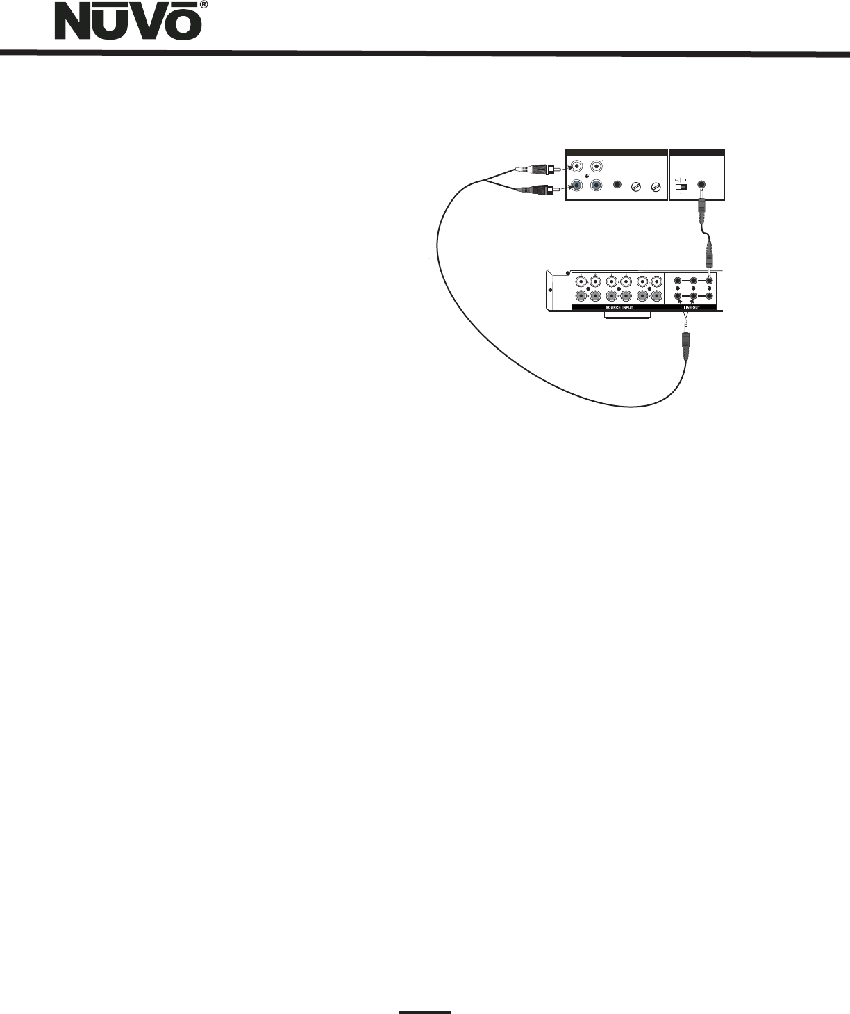
R
L
SENSITIVITY
OdBV = 1.0RMS
-12
+6
0
LEFT
+6 -12
RIGHT
0
AUDIO
INPUT
2
INPUT OUTPUT
CONTROL
VOLTAGE
TRIGGER
3-30 VOLTS
AC OR DC
ON/OFF SWITCH
AUDIO AC/DC
POWER
MODE
CONTROL
56 FIXED VAR
ZONE
1
ZONE
2
NV-P2100 Amplifier
Essentia Amplifier
36
NV-P2100 200-Watt Auxiliary Amplifier (Fig. 55)
RS232 Interface
The P2100 is specifically designed for use with the NuVo
Systems' lineouts. It can be used with either the fixed or
variable lineouts available for zones 1 and 2 on the Essentia
amplifier. The connection is made using either a 1/8”
(3.5mm) to 1/8” stereo patch cable or a 1/8” stereo to RCA
patch cable.
There are two methods for triggering the P2100 from the
Essentia outputs. One is to set the POWER MODE switch on
the P2100 to AUDIO (extreme left) position and allow an
incoming audio signal from the Essentia System to turn on
the P2100. The second method is to place the POWER MODE
switch in the AC/DC (extreme right) position. This will turn
on the P2100 when the Essentia is on.
An additional feature of Essentia is Zone-Specific Triggers
that will trigger the P2100 only when that zone is turned on.
Utilizing the voltage trigger requires a mono 1/8” (3.5mm)
patch cable from either the System ON output on the
Essentia to the P2100 Voltage trigger input, or from the
specific Zone Trigger on the Essentia to the Voltage Trigger
on the P2100, as shown in Fig. 55.
The RS232 port allows external two-way communication with
the Essentia System. Home automation systems can be set
up to operate Essentia. The RS232 protocol document is
available for download from NuVo’s website Prozone at
www.nuvotechnologies.com/prozone.
TRIG
Fig. 55

37
NV-E6GMS Essentia System
· NV-E6GM Essentia G Main Amp
· 6 NV-E6GCP-DC Decora style* Control Pads with
white, ivory, almond and black screwless trim plates
· 1 NV-GRC1 Remote Control
· 6 NV-VEC visible IR emitters
· 1 NV-E6GMAP-DC Main Allport connection hub
1 NV-E6GAPC Essentia Allport Cable
· 1 NV-NC1 10 foot network cable
· 1 NV-PC2-NA IEC 2 wire Power Cable (USA models
only)
·
· 1 pr. NV-REM1U Rack Ear Mounts
NV-E6GXS Essentia Expander System
· NV-E6GX expander amplifier
· 6 NV-E6GCP-DC Decora style* Control Pads with
white, ivory, almond and black screwless trim plates
· 1 NV-GRC1 Remote Control
· 1 NV-E6GXAP-DC Expander Allport connection hub
· 1 NV-E6GAPC Essentia Allport Cable
6 NV-RCAY3 3 foot RCA stereo “Y” Cable
·
·
· 2 NV-NC 1 foot network cables
· 1 pr. NV-REM1U Rack Ear Mounts
1 NV-PC2-NA IEC 2 wire Power Cable (USA models
only)
Essentia Package Contents
Essentia Specifications
Zones 1-6 Power Amplifier Outputs
Zones 1 and 2 Preamplifier Outputs
Source Inputs 1-6
IR Emitter Outputs
System
Continuous Average Output Power 40W (20W x 2)
Two channels driven 30-20kHz @1% THD
Rated Distortion (1/2 power) 0.40%
Rated Impedance 6 Ohms
Damping Factor 50+
Frequency Response (20-20kHz) ±2 dB
Variable output 0-2.4V
Fixed output 2.4V
Impedance 1k Ohms
input Impedance 20K
Input Sensitivity for rated power 300mV RMS
Input Overload 2.4V RMS
Source Outputs 6
Sum Outputs 1
Output Drive Current 20mA
Output Drive Voltage 5V
Compatible with single and dual emitters
System On Output 5V @ 20mA
External Mute Input 3.3-10V DC
Zone Trigger Outputs
Power Requirements
Physical Specifications
Output Power 5V @ 20mA
Outputs 2 (zones 1,2)
Power Supply 85-265VAC 50/60Hz
Power Consumption all channels 150VA (150W)
at maximum available output
Power Consumption average 70VA (70W)
operating conditions
Power Consumption no signal 18VA (12W)
Standby Power Consumption 0.8 W
USA Safety Listing (UL 6500)
Canada Safety Listing (CAN/CSA E60065.00)
CE Listing/SEMKO (EN60065, EN55013,
EN55020, EN6100-3-2, EN6100-3-3/A1)
Australia C-Tick
ENERGY STAR
Unit Size Millimeters 44Hx430Wx250D
Unit Size Inches 1 3/4Hx17Wx97/8D
Shipping Size Millimeters 265 x 558 x 375
Shipping Size Inches 10 1/2 x 22 x 14 3/4
Unit Weight Kilograms 3.0
Unit Weight Pounds 6.65
Shipping Weight Kilograms 7.5
Shipping Weight Pounds 16.5
Keypad Size Millimeters 66Hx33Wx30D
Keypad Size Inches 2 5/8Hx11/4Wx11/8D
NuVo reserves the right to change specifications without notice.
Serial Port
Baud Rate
No Parity
No Flow Control
57,600
Data Bits 8
Stop Bits 1
* Decora is a registered trademark of the Leviton Corporation

38
Troubleshooting
Symptom Probable Cause Remedy
One of the zone Control Pad displays a
“NuVoNet Not Detected” message.
Zone CAT5 is plugged into the Accessory
jack on the back of the Control Pad instead
of the NuVoNet jack. Improperly wired
CAT5 Cable.
Check the CAT5 connection at the back of
the Control Pad. Plug the Control Pad
directly into the Network cable and into
the NuVoNet input on the Essentia.
The amplifier is plugged in and turned on,
but the STAND BY LED is not lit and none of
the system functions work.
This is most likely caused by a blown fuse
on the power supply.
The fuse is accessed internally on the
power supply. It requires a 4 amp time
delay fuse.
All of the system’s Control Pads display a
“NuVoNet Not Detected” message.
The MCU card internal to the Essentia is
damaged, or the data (blue and blue
stripe) conductors on one or more of the
CAT5 cables are shorted or not making
good contact in the RJ45 connectors.
Remove all of the CAT5 connections from
the system and test cables one at a time.
If the issue is a shorted CAT5, the
symptom will display when that cable is
connected to the system. A damaged
MCU must be replaced by NuVo.
With the Control Pads plugged in, the
POWER LED on the front of the amplifier will
not turn on.
One or more improperly wired CAT5 cables. Make sure the amplifier is turned on. Test
that the POWER LED on the amplifier
turns on when the Network Cable is
unplugged. Next, unplug all the CAT5
cables from the Allport and plug them
back in one at a time until the bad
cable(s) is discovered.
The IR repeater does not properly control
the audio source equipment.
One or more of the IR emitters are not
properly placed over the IR receiver on the
audio source equipment, or the IR output
number on the Essentia does not
correspond with the audio equipment you
are controlling.
Reposition the LED end of the emitter on
the face of the source equipment, so it
is flashing directly over that source’s IR
receiver. Make sure the emitter plugged
into IR Output #1 is actually going to
source #1 , and so on for sources 2-6.
When the Control Pad is plugged in there is
a loud pop through the speakers and the
Control Pad does not work.
Improperly wired CAT5 cable. Check that you are using the 568A or B
wiring standard (see section I: Crimping
CAT5 wire). The best way to know is to
use a CAT5 tester.

Troubleshooting
The IR repeater does not properly control
the audio source equipment.
The NuVo IR output is not set at the best
carrier frequency.
Within IR Library tab of the Configurator
Software, each library has a “Properties”
button. This button has a drop down
menu that lets you select different
carrier frequencies from 38kHz to
56kHz. This will default the library to the
selected frequency. Cable and Satellite
typically needs the 56kHz setting.
Symptom Probable Cause Remedy
The IR repeater does not properly control
the audio source equipment.
An External light source is interfering with
IR communication through the system.
In the Configurator Software (see pg.
19, or in the Advanced
Zone Setup menu (see pg. 27
at any Control Pad, you have
the ability by zone to “Disable” the IR
receiver. This will prevent direct
sunlight, or possibly, plasma and
fluorescent light from affecting IR
response through the other zone
receivers.
IR Passthrough),
Remote
Controls),
When downloading a Configuration to the
Essentia Main amplifier, a “board not
found” error message appears on the
computer screen.
This occurs when the Essentia is not
plugged into an AC power source, or a
faulty USB to RS232 conversion cable.
A communication error can be as simple
as not plugging the Essentia in prior to
the download. Often the error is also
corrected by closing and reopening the
Configurator Software, or if you are
using a USB to RS232 cable for
communication, try a different cable. If
these do not correct the error, it could
be a faulty MCU board in the Essentia.
39
www.nuvotechnologies.com
NuVo Technologies LLC Hebron, Kentucky USA
E6G 0818
