Ogemray Technology WF5370M08 USB Wireless Module User Manual
OGEMRAY TECHNOLOGY(HK)CO., LIMITED USB Wireless Module
UserManual.wiki
>
Ogemray Technology
>
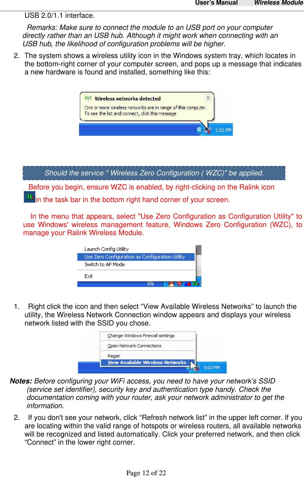
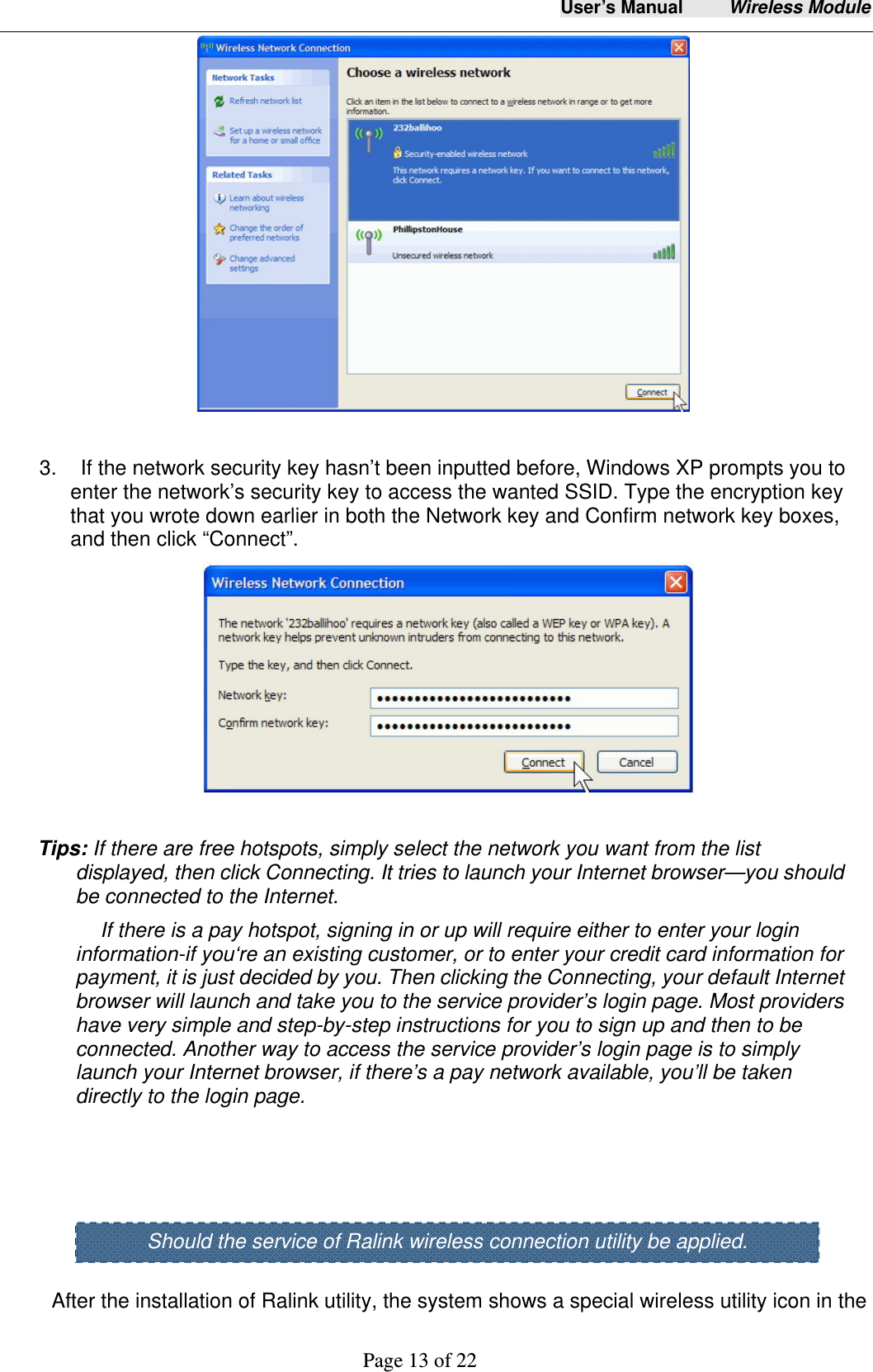
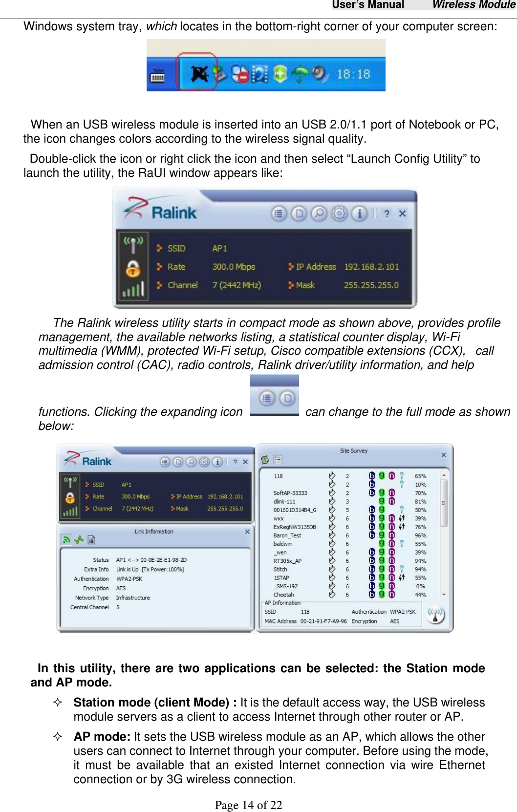
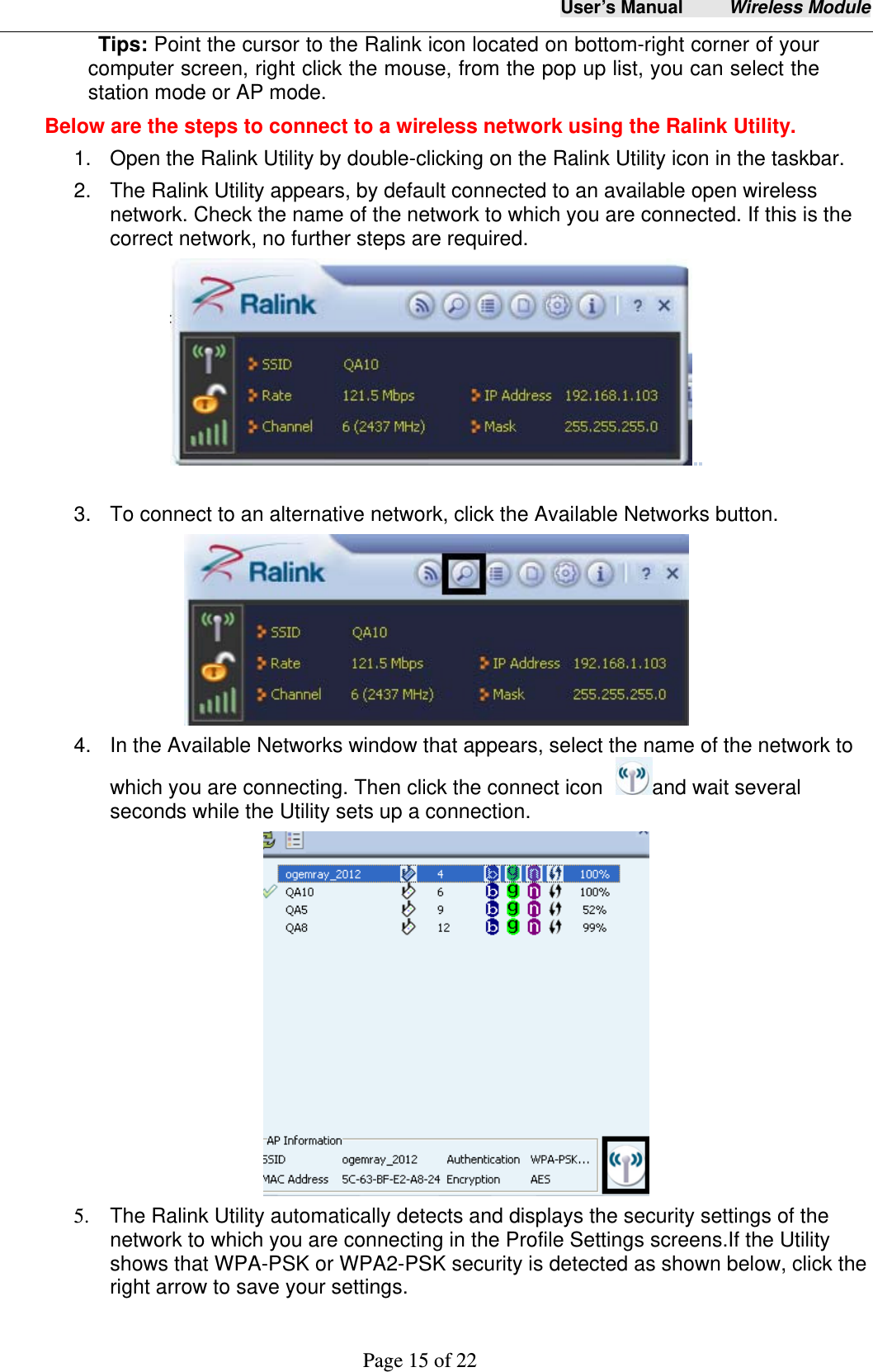
WF5370M08 User Manual
User Manual
Navigation menu
Upload a User Manual
Namespaces
Wiki Guide
HTML
PDF
Info
Views
User Manual
Discussion / Help
Navigation