Oticon A S AUMRTE Radio model for hearing instruments User Manual COMPANY LETTER HEAD
Oticon A/S Radio model for hearing instruments COMPANY LETTER HEAD
Contents
- 1. InstallationInstructions
- 2. installation guide
InstallationInstructions
PEOPLE FIRST
Oticon Radio Model - Quick Installation Guide
Radio Model Name:
Aurora mini RITE-T
Oticon A/S
Main +45 39 17 71 00
Kongebakken 9
Fax +45 39 27 79 00
DK-2765 Smørum
Denmark
www.oticon.com
CVR-no. 42334219
1
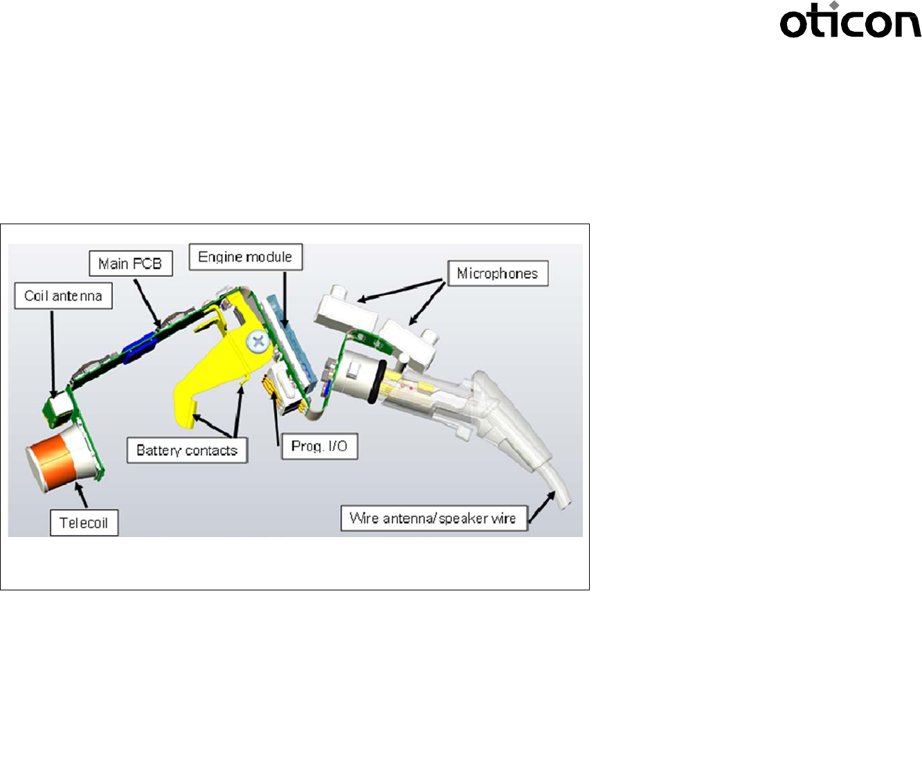
The Aurora mini RITE-T radio model contains two radio transceivers running at 3.84 MHz and 2.4 GHz and both implemented on a single hardware platform.
The radio model is implemented on the main PCB is shown
to the left in 3D with connections to the antennas, the
microphones, the speaker and the battery terminals.
The 3.84 MHz radio is a low power, short range, inductive
radio transceiver working at a single channel at 3.84 MHz
using MSK modulation with 320 kbit/s data rate and
connected to a small coil antenna.
The 2.4 GHz radio is a Bluetooth ® Low Energy (BLE)
transceiver using GFSK modulation with 1 Mbit/s data rate
also capable of proprietary modes with higher data rates and
connected to a short wire antenna.
Aurora mini RITE-T Radio Model – 3D overview
PEOPLE FIRST
Oticon Radio Model - Quick Installation Guide
Radio Model Name:
Aurora mini RITE-T
Oticon A/S
Main +45 39 17 71 00
Kongebakken 9
Fax +45 39 27 79 00
DK-2765 Smørum
Denmark
www.oticon.com
CVR-no. 42334219
2
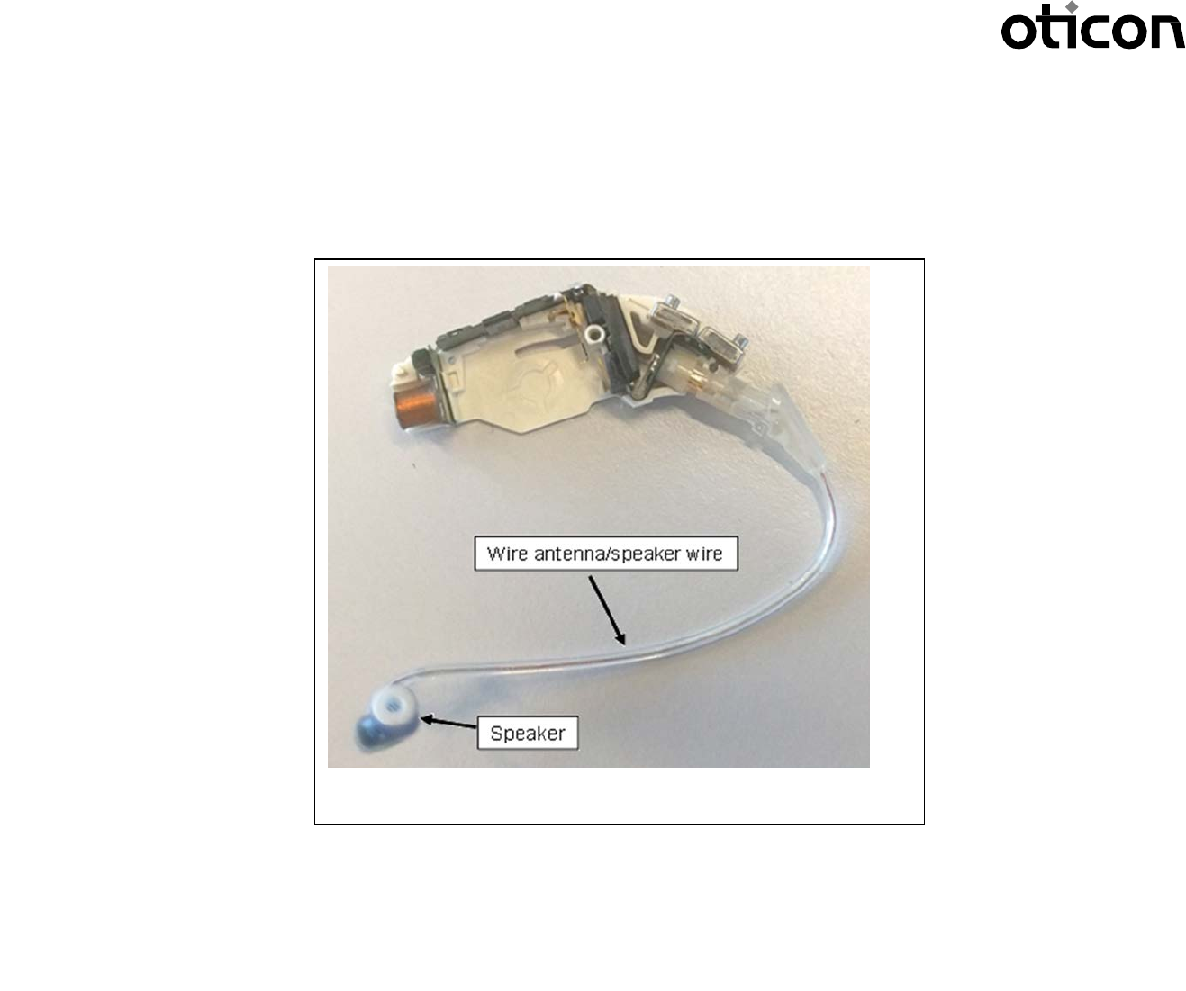
This image shows, how the wire antenna is connected to the radio model inside the hearing aid plastic shells:
Aurora mini RITE-T Radio Model – 3D overview part two.
PEOPLE FIRST
Oticon Radio Model - Quick Installation Guide
Radio Model Name:
Aurora mini RITE-T
Oticon A/S
Main +45 39 17 71 00
Kongebakken 9
Fax +45 39 27 79 00
DK-2765 Smørum
Denmark
www.oticon.com
CVR-no. 42334219
3
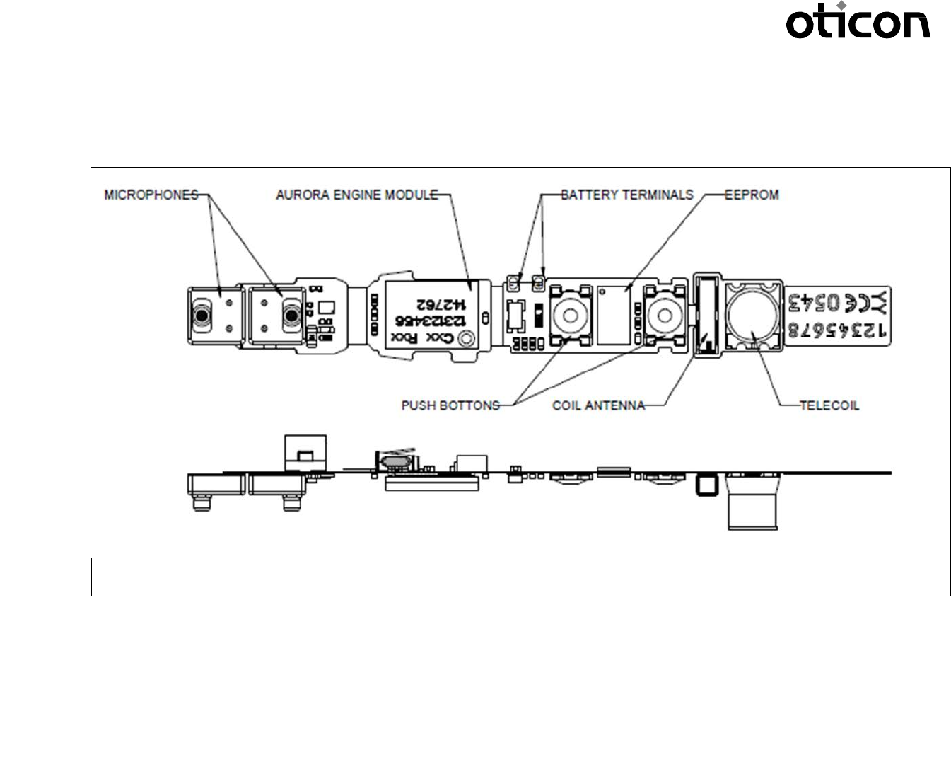
Below the main flex PCB of the Aurora mini RITE-T radio model with the most important electrical and electro-mechanical components can be seen:
The most important part of the radio model is the Engine Module mounted on the main flex PCB, which connects it to both the EEPROM memory and all external
connections: On the top side these are the microphones, the battery terminals and the push button.
The Aurora mini RITE-T radio model requires only a single cell battery and an external speaker (also incl. the wire antenna for the Bluetooth radio part) to
be attached and plastic shells, defining the industrial design of a hearing aid end product and holding everything together, in order to be operational.
Aurora mini RITE-T Radio Model – Main PCB – Top side
PEOPLE FIRST
Oticon Radio Model - Quick Installation Guide
Radio Model Name:
Aurora mini RITE-T
Oticon A/S
Main +45 39 17 71 00
Kongebakken 9
Fax +45 39 27 79 00
DK-2765 Smørum
Denmark
www.oticon.com
CVR-no. 42334219
4
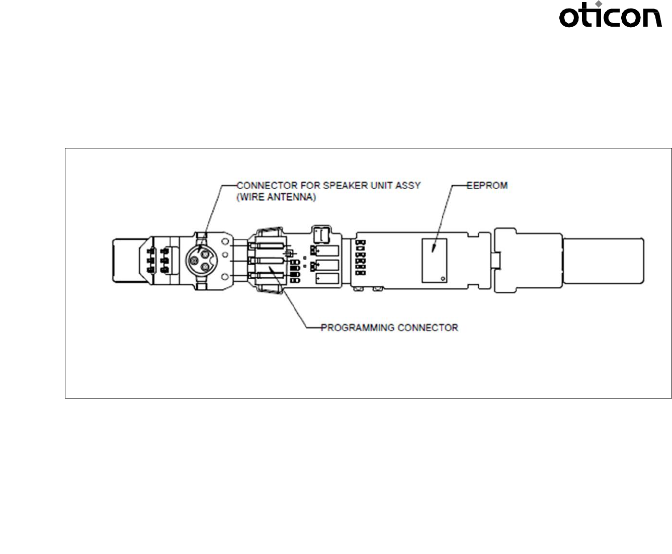
On the bottom side of the main PCB of the Aurora mini RITE-T radio model the connector for the speaker unit assembly (where the wire antenna for the Bluetooth
radio is an integrated part), the programming connector, an other EEPROM memory and coil antenna for the 3.84 MHz radio can be seen:
The most important parts inside the Engine module are a Digital-Signal-Processor (DSP), a radio Front-End (FE) chip for the 3.84 MHz radio part and an RF chip
for the Bluetooth radio part – all mounted on a small rigid PCB again mounted on the main flex PCB. The Aurora mini RITE radio model also includes all voltage
regulators and buffered data programming inputs on board. The DSP is the main processor controlling the functionality of both radios in the Aurora mini RITE
radio model.
The Aurora mini RITE-T radio model is intended to be installed in Oticon, Bernafon, Sonic and affiliated wireless hearing aid devices of the mini RITE-T
(Reciever-In-The-Ear-with-Telecoil) wearing style.
Aurora mini RITE-T Radio Model – Main PCB – Bottom side