Otto Bock HealthCare MHG0482 Remote Control for low limp hightech prostheses User Manual Manual
Otto Bock Healthcare Products GmbH Remote Control for low limp hightech prostheses Manual
Manual
3C98-1/3C88-1
C-Leg® Knee Joint System
Instructions for Use.......................................................... 2
© Otto Bock HealthCare · 647H215=GB 07.06/1 PDF Printed in Germany
3
Table of Contents
tion................................................................................................24
1.1 Medical purpose......................................................................................................................24
1.2 Field of application ..................................................................................................................24
1.3 Operational conditions.............................................................................................................25
1.4 Qualification of the prosthetist .................................................................................................25
1.5 Safety instructions ...................................................................................................................25
.....................................................................................................27
2.1 Connecting the tube adapter .................................................................................................27
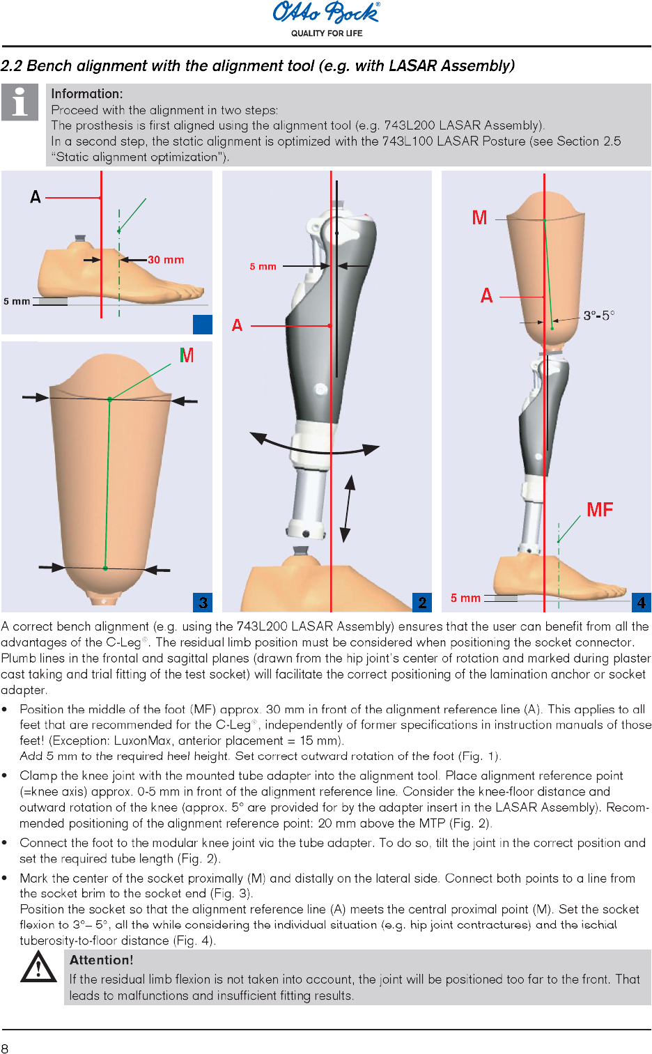
2.2 Bench alignment with the alignment tool (e.g. with LASAR Assembly)......................................28
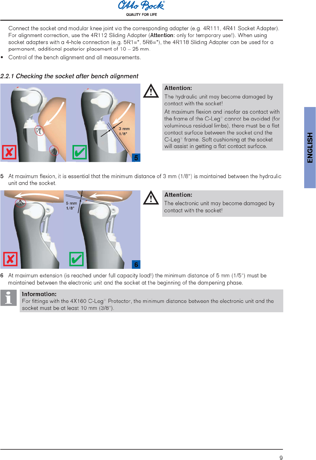
2.2.1 Checking the socket after bench alignment..............................................................................29
2.3 Torque values of the screw connections ..................................................................................30
2.4 Charging the C-Leg® knee joint system ...................................................................................31
2.5 Static alignment optimization (with LASAR Posture).................................................................32
2.6 BionicLink/optional: Serial data cable......................................................................................33
2.7 C-Soft .....................................................................................................................................33
2.7.1 C-Soft in the Otto Bock Data Station (back folded page) ........................................................34
2.7.2 Otto Bock C-Soft (back folded page) ......................................................................................34
2.8 Optional: Parameter settings with foam cover and C-Soft........................................................35
2.9 Remote control and switching into 2nd mode ............................................................................35
2.9.1 Switching modes with the remote control.................................................................................36
2.9.2 Configuration of the standing mode and the 1st mode with remote control................................36
2.9.3 Changing the battery of the remote control ..............................................................................37
2.9.4 Optional: Switching between 1st mode and 2nd mode without the remote control ......................38
2.10 Finalizing the prosthesis...........................................................................................................38
2.11 Important user instructions.......................................................................................................38
3 Additional Information............................................................................................................40
3.1 Service intervals ......................................................................................................................40
3.2 Damage events .......................................................................................................................40
3.3 Technical information...............................................................................................................40
3.3.1 Symbols on the joint.................................................................................................................40
3.3.2 Symbols on the remote control.................................................................................................40
3.4 Transport.................................................................................................................................40
3.5 Warranty .................................................................................................................................40
3.6 Liability ....................................................................................................................................41
3.7 Declaration of conformity .........................................................................................................41
4
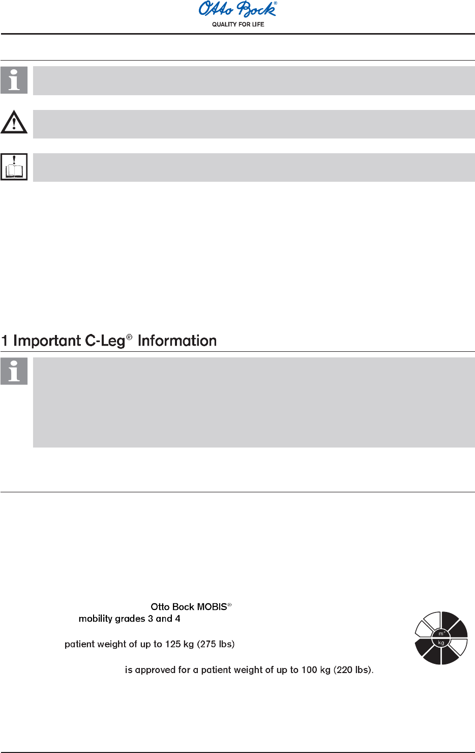
Explanation of symbols used in these Instructions for Use
Information:
Important information about the fitting, use, patient instructions and the product.
Attention/Caution:
Warning signal for possible technical damages / Warning signal for possible risk of accident or injury.
Note:
Reference to another instructions for use.
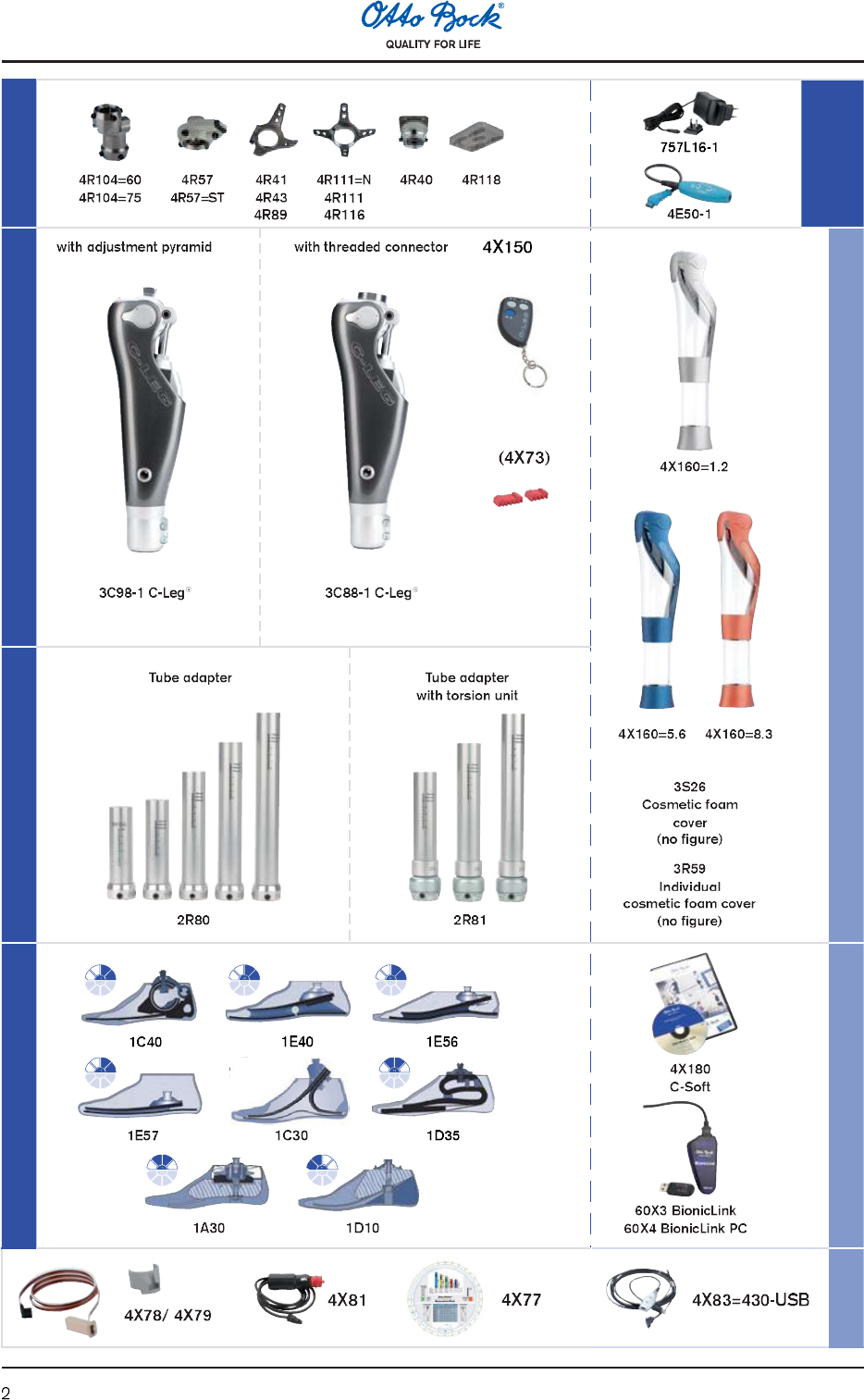
Recommended accessories for prosthetists:
710D4 Torque Wrench
710Y2=5 Hex Bit
743L100 LASAR Posture (647H189 Instructions for Use)
743L200 / 743L300 LASAR Assembly (647H193 Instructions for Use)
60X3 BionicLink (647G192 Instructions for Use)
4X180 C-Soft (647G268 Instructions for Use)
Information:
Before using the C-Leg®, please read these Instructions for Use thoroughly! Please pay special attention
to the safety instructions!
The patient must be taught how to handle, care for and operate his/her prosthesis properly. Please see
the following sections: 1.3 Operational conditions, 1.5 Safety instructions, 2.4 Charging the C-Leg®
knee joint system, 2.9 Remote control and switching into 2nd mode, 2.11 Important user instructions,
3.1 Service intervals, 3.3 Technical information, 3.6 Liability
1.1 Medical purpose
The C-Leg® knee joints 3C98-1 and 3C88-1 are to be used exclusively for the exoprosthetic fitting of the lower
extremity.
1.2 Field of application
The C-Leg® was designed for a broad field of application and can be used by transfemoral amputees as well as by
active hip disarticulation amputees. For knee disarticulation amputees, a version for long residual limbs is available
(3C88-1).
Field of application according to the Mobility System:
Recommended for (unrestricted outdoor walkers and unrestricted outdoor
walkers with especially rigorous demands).
Approved for a .
Exception:
The 2R80=110 Tube Adapter
5
1.3 Operational conditions
Information:
Advise your patients of the information in this section.
The C-Leg® was developed for everyday activities and not for extreme sports such as free climbing, parachuting or
paragliding. For the necessary environmental conditions, please see Section 3.3 Technical information.
The C-Leg® prosthesis system is designed exclusively for use on one patient. Use of the product by a further person
is not approved by the manufacturer.
The fitting of a patient with a C-Leg® may only be carried out by prosthetists who have been authorized with the
corresponding Otto Bock training.
1.5 Safety instructions
Information:
Advise your patients of the information in this section.
Attention:
Failure to follow the below-mentioned safety instructions can lead to a faulty control or malfunction of the
C-Leg® and result in risk of injuries for the patient as well as damages to the C-Leg®.
General Safety Instructions
Participation in an Otto Bock product training course for the C-Leg® is obligatory before the first fitting. Additional
product training courses may become necessary to qualify for fitting product updates.
In the interest of the patient (operational safety and warranty), the C-Leg® should be sent in for maintenance at
the specified service intervals.
Do not shorten the tubes as that may damage the integrated strain gauges.
During the data transfer (PC to C-Leg®), the patient must remain still and the BionicLink or the communication
cable must not be removed.
Patients who have been using forearm crutches or a cane during the dynamic adjustment of the maximum load
generally become more active within a very short time. For that reason it is indispensable to check and possibly
readjust the settings. A readjustment of the C-Leg® settings is also required for patients who switch from forearm
crutches to a cane or to no walking aid at all.
Any changes or modifications of the device can lead to restrictions of usage. Patients are to be advised about
the charging procedure, the proper handling of the remote control as well as the switching into the 2nd mode. The
following patient information (pages 6 f.) should be handed to the patient.
The opening and repairing of the joint may only be performed by authorized Otto Bock technicians and the
handling of the battery may only be carried out by Otto Bock service centers (exchanges are not permissible).
The C-Leg® may only be used with the specified prosthetic feet and must not be used with components from other
manufacturers (warranty will become void). (Please see component overview on the folded front page).
Always use the shipping case for transport.
6
Patient Information
In the case that you commanded an unwanted action with the remote control by mistake (vibration or sound sig-
nal), relieve the C-Leg® of any load and rectify the command.
Avoid proximity to strong magnetic and electric interference sources (e.g. transformer stations, high-powered
radio or television transmitters) as well as areas with extreme temperatures or humidity.
Do not subject the system components to intensive smoke, dust, or mechanical vibrations or jolts.
Neither solid particles nor liquids should penetrate the system components. Should the joint come into contact
with liquid, remove the cosmetic cover and let the components dry. The joint should then be sent to an authorized
Otto Bock service for inspection. Your prosthetist is the contact person.
Should the C-Leg® come into contact with salt water, clean it immediately with a cloth moistened with freshwater
and let it dry. The joint should then be sent to an authorized Otto Bock service for inspection. Your prosthetist is
the contact person.
The C-Leg® has been developed for everyday use and must not be used for unusual activities such as extreme
sports (i.e. free climbing, paragliding, etc.). Careful handling of the prosthesis and its components not only
increases their service life but, above all, ensures the patients safety. Should the prosthesis be subjected to un-
usual stress (e.g. a fall), contact your prosthetist immediately and have the prosthesis inspected for any damage.
If necessary, the responsible prosthetist will pass the prosthesis on to the Otto Bock Service.
The hydraulic unit may overheat during extended, continuous use (e.g. lengthy downhill walks). In that case, the alarm
will repeatedly vibrate to alert you of the risk of overheating. As soon as these vibrations begin, stop all activities and
allow the hydraulic unit to cool down. Avoid touching the hot parts! You may resume your activities once the vibration
signals stop. If activities are continued despite the vibration signals, the hydraulic element may overheat and, in
extreme cases, lead to a damage to the C-Leg®. The joint should be serviced following a case of overheating.
When walking backwards, always put your heel down first. Putting down the toe first when walking backwards
results in the risk of falling, because the C-Leg® can then switch from the high stance phase value to flexion.
When walking up or down stairs, always use the banister or handrail. When walking down stairs the prosthetic
foot should be placed on the step so that the heel and posterior half of the foot contact the tread surface; the fore-
foot may extend beyond the riser to make knee flexion easier.
Stop walking up or down the stairs immediately whenever the sound warning beeps. Make careful tests to verify if
the stance phase stabilization is active (see Section 2.11 Important user instructions).
When the C-Leg® is not in use for an extended period of time, the battery may become discharged. We therefore
recommend recharging prior to use.
Prior to using the C-Leg® in the 2nd mode (e.g. bike riding), check the battery status. To do so, attach the charger
to the C-Leg®. The yellow LED should flash (battery is charged more than a half) or should not be lit (battery is
fully charged). Using the C-Leg® in the 2nd mode with insufficient power supply may cause the joint to switch into
the safety mode (see Section 2.11 Important user instructions).
An incorrect switch from the 2nd mode into the 1st mode creates the risk of falling (see Section 2.9 Remote control
and switching into the 2nd mode)!
For your own safety, comply with the specified service and inspection intervals.
The ability of leg prosthesis users to drive a vehicle is determined on a case-by-case basis. Criteria include the type
of fitting (amputation level, unilateral or bilateral, residual limb conditions, design of the prosthesis) and the ampu-
tees individual abilities. All persons are required to observe their countrys national and state driving laws when
operating vehicles. For insurance purposes, drivers should have their driving ability examined and approved by an
authorized test center. Otto Bock recommends that the vehicle be professionally retrofitted to the users individual
needs (e.g. automatic shift). Risk-free driving must be ensured even when the prosthesis is not functioning.
Always use the protective plugs.
Pay attention to the vibration and sound warnings (beeps) of the C-Leg®.
7
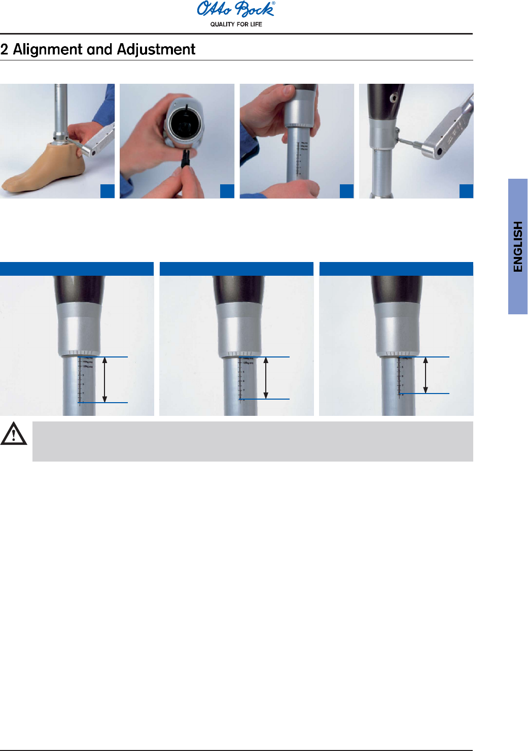
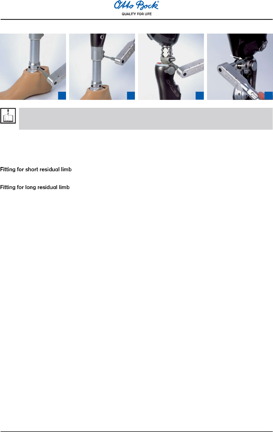
2.1 Connecting the tube adapter
1 2 3 4
1Mount the foot to the tube adapter (lightly tighten the screws).
2Plug the tube adapter plug onto the knee joint (only one polarity possible).
3Push the protruding cable into the tube and push the tube adapter into the C-Leg®. In doing so, take care to
achieve the minimum insertion depth (see following table).
max. 75 kg / 165 lbs 75 kg - 100 kg /165 lbs - 220 lbs 100 kg - 125 kg /220 lbs - 275 lbs
50 mm
max. adjust-
ment range
45 mm
max. adjust-
ment range
40 mm
max. adjust-
ment range
Caution:
With the 3C98-1 and 3C88-1 models, the scaling must be positioned in front of the tube (With the former
models 3C98 and 3C88, the scaling had to be on the back of the tube).
4Turn the foot slightly outward (adjustment range +/-30° to suit the needs of the patient) and pre-fasten the
screws lightly at the clamp.
10
2.3 Torque values of the screw connections
1 2 3 4
15 Nm 7 Nm
10 Nm
15 Nm
Information:
The torque values for additional as well as optional system components (in item 3 below) are indicated in
the instructions for use of those products.
Using the 710D4 Torque Wrench with the 710Y2=5 Hex Bit, turn the screws alternatively to the prescribed torque
so that the torque is gradually increased:
1Tube adapter: 15 Nm
2Clamp: 7 Nm
3Rotation adapter or sliding adapter: 15 Nm
4Lamination anchor with threaded connector: 10 Nm
11
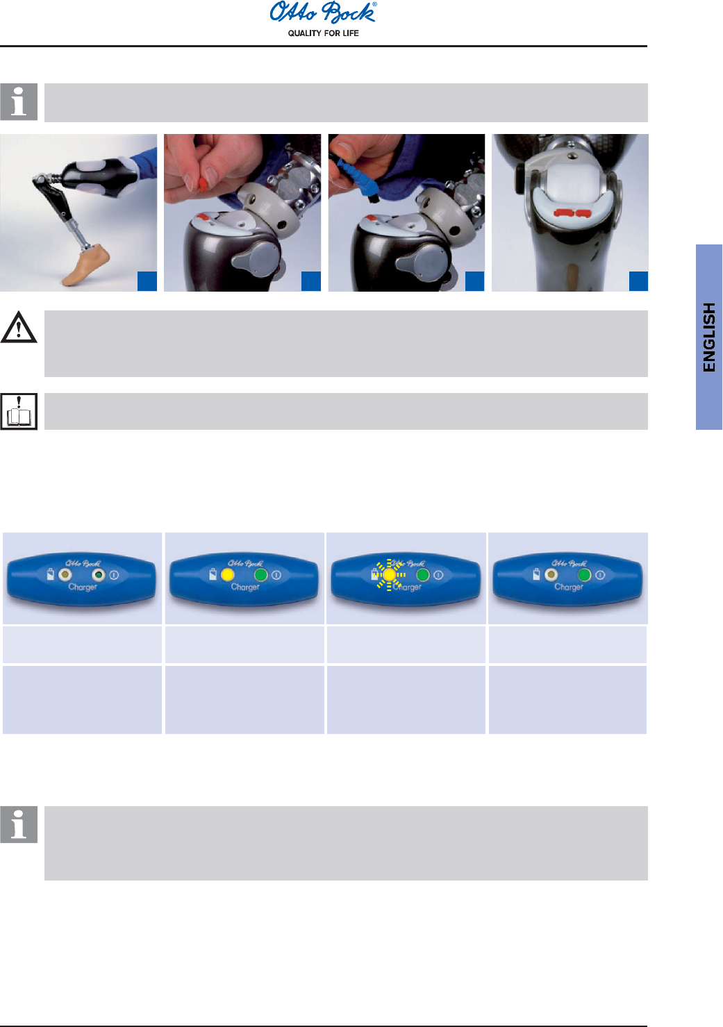
2.4 Charging the C-Leg® knee joint system
Information:
Advise your patients of the information in this section.
1 2 3 4
Caution:
Take off the prosthesis prior to charging.
Attention:
During charging, keep the C-Leg® fully flexed.
Note:
Prior to charging with 4E50-1 Charger, read the corresponding 647G262 Instructions for Use.
The battery is empty upon delivery. The battery of the C-Leg® must therefore be charged prior to the first fitting of
the patient.
1Bend the C-Leg® until it hits the stop.
2Remove the 4X73 Protective Plug for the C-Leg®.
3Connect the 4E50-1 Charger and verify the charging status (see following figures).
Both LEDs are off. Both LEDs are lit. Yellow LED flashes.
Green LED is lit.
Yellow LED is off.
Green LED is lit.
No power supply (or
defective charger)
Battery is being charged.
Battery capacity is lower
than 50%.
Battery is being charged.
Battery capacity is above
50%.
Battery is fully
charged
(or connection with
C-Leg® is interrupted).
4After charging, remove the charging plug (C-Leg® performs self-test and activates 1st mode) and reattach the
protective plug.
Information:
The capacity of a fully charged battery is sufficient for one full day. We recommend charging the battery
over night when using the prosthesis on a daily basis.
Charging is only possible at temperatures above 0 °C.
12
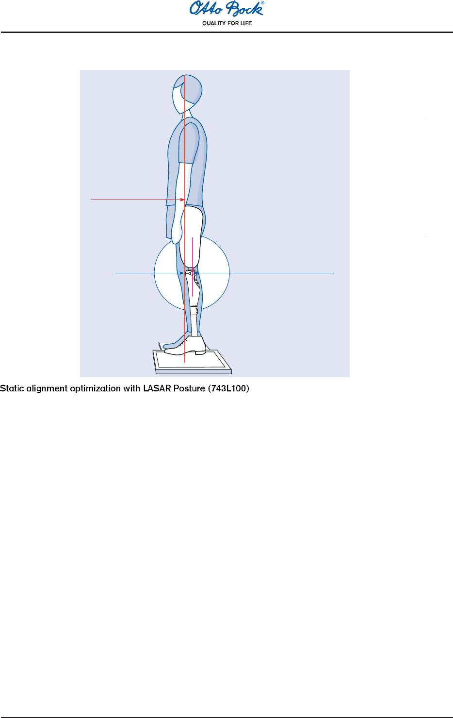
2.5 Static alignment optimization (with LASAR Posture)
Load line 30 mm in
front of alignment
reference point
Load line
Alignment reference
point
The static alignment can be considerably optimized with the help of the LASAR Posture. In order to ensure an
appropriate stability and at the same time an easy swing phase initiation, proceed as follows:
1After the self-calibration of the LASAR device, the load line can be measured. For that, the transfemoral ampu-
tee steps onto the force sensing plate with the C-Leg® and onto the height compensation plate with the other
leg. The prosthesis side must be sufficiently loaded (>35% of body weight).
2The alignment is adapted exclusively by modifying the plantar flexion so that the load line/laser line runs approxi-
mately 30 mm in front of the alignment reference point (=knee axis) of the C-Leg®.
3After adjusting the C-Leg® with C-Soft® (see Section 2.7 C-Soft) perform dynamic optimizations during trial
walking.
13
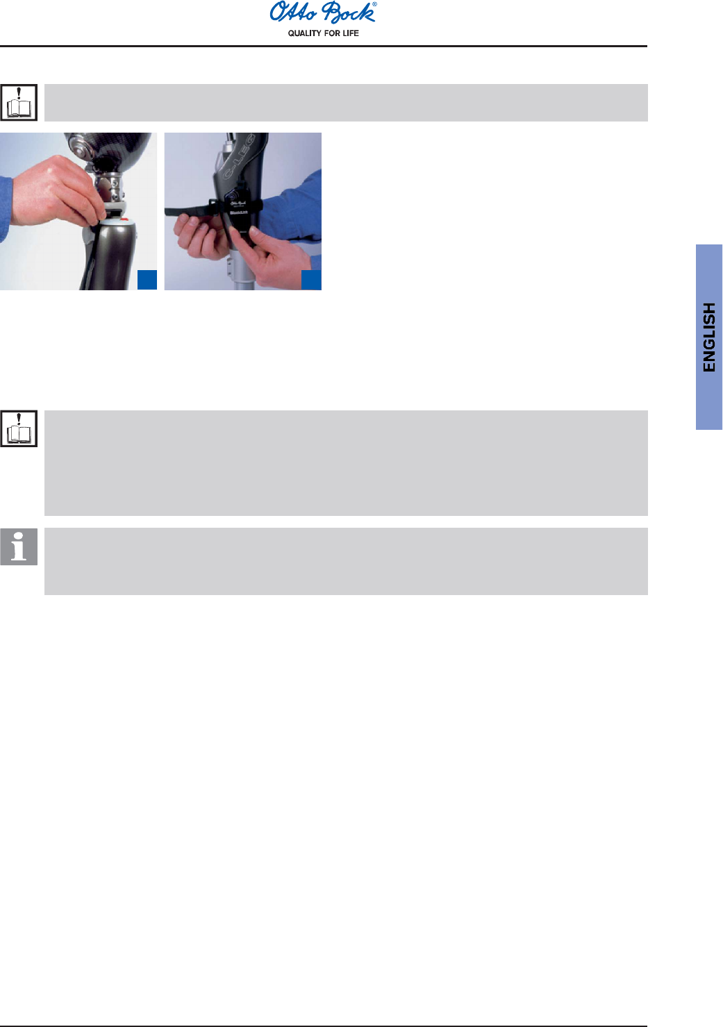
2.6 BionicLink/optional: Serial data cable
Note:
Prior to connecting the 60X3 BionicLink, read the corresponding 647G192 Instructions for Use.
1 2 3 4
1Connect the wireless adapter cable (BionicLink) (optional: connect serial data cable).
2Engage the BionicLink into the C-Leg® and attach it medially (for left fittings) or laterally (for right fittings) at the
C-Leg®.
2.7 C-Soft
Note:
Prior to the parameter adjustment with 4X180=V1.0 C-Soft, read the corresponding 647G268 Instruc-
tions for Use.
Prior to the parameter adjustment with the old Sliders adjustment software, download and read
the corresponding instructions for use at www.ottobock.com/en/sliders. The remainder of this sec-
tion can then be skipped.
Information:
Otto Bock Data Station is the platform for Otto Bock applications such as C-Soft and others.
Otto Bock C-Soft cannot be used without the Otto Bock Data Station. The Otto Bock Data Station is a
standard component of C-Soft and is automatically installed when installing C-Soft.
14
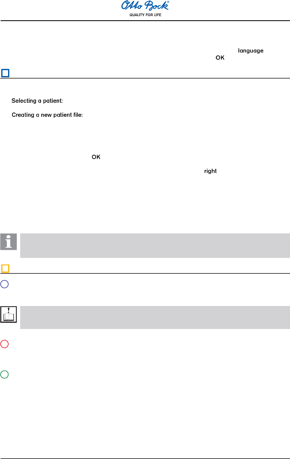
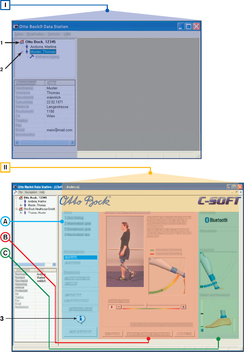
2.7.1 C-Soft in the Otto Bock Data Station (back folded page)
Changing the language in the software (optional):
In the menu, select Edit - Options with the left mouse key. In the next window, select the tab . Select
the desired language (by selecting the field in front of the language) and confirm with .
IOtto Bock Data Station
1 Selecting or creating a patient file:
- Select the symbol or text for Company (Marking 1).
- See point 3
- In the menu File select the sub-category New patient.
2 Entering the patients name and personal data:
- In the window Patient data enter all personal data of the patient.
When selecting the field Address, further patient data appears. All fields marked with an asterisk * must
be filled out.
Confirm the entry by clicking .
3 Starting C-Soft:
- Select the patient file (patient) with the left mouse button (Marking 2). With mouse button, click on the
selected patient, and in the following window, click on Start C-Soft with the left mouse button.
4 Establishing the connection:
- By clicking on the corresponding tab, select the type of connection (Bluetooth or RS232/ USB). Then
establish the connection by selecting Autoconnect (Automatic Establishment of Connection).
2.7.2 Otto Bock C-Soft (back folded page)
Information:
The program does not effect any automatic changes to the settings. The adjustment begins following the
successful connection establishment with Step 1. The individual steps are explained with text and images.
II Otto Bock C-Soft
ANavigation section:
- All adjustments can be performed in steps (1, 2, etc.). Adjustment steps that are not feasible are highlighted
in gray.
Note:
Read the additional information for every new adjustment!
The information can be viewed by clicking on the Information field (Marking 3).
- Very experienced users can also use the expert mode by clicking on the Expert mode button.
BAdjustment section:
- All adjustment steps (1, 2, etc.) are explained with text and images. Follow the instructions to adjust the joint.
- You can navigate back and forth between the individual adjustment steps (1, 2, etc.) with the Next and
Back buttons.
CStatus section:
- The status of the connection, battery, as well as knee angle, maximum load, toe load and heel load are
dynamically visualized in real time.
15
2.8 Optional: Parameter settings with foam cover and C-Soft
The foam covers 3S26 or 3R59 can be used for the cosmetic enhancement of the leg prosthesis.
For that purpose, a 4X78 Charger Extension Cable can be integrated in the C-Leg® fitting. If the charger extension
cable is not used, a connection cap made of 2 mm Pedilin® allows to pull down the foam cover in order to reach the
charging receptacle at the C-Leg®.
Allow a 60 mm compression allowance to minimize the effect of the protective foam cover on the knee function.
When determining the proper cover length, increase the thigh dimension by 30 mm and the shin dimension by the
same amount.
The mounted foam cover changes the damping behavior. With the 60X3 BionicLink (wireless programming inter-
face), which is attached below the pre-shaped foam block, the damping behavior can be completely taken into
account by adapting the parameter settings.
That process furthermore requires the 60X4 BionicLink PC for the data transfer and the 4X180 C-Soft for the pa-
rameter adjustment (see Section 2.7 C-Soft ).
2.9 Remote control and switching into 2nd mode
Information:
Advise your patients of the information in this section.
For normal operation, the C-Leg® can be used in the 1st mode (optional with standing mode) and in the 2nd mode.
The 1st mode is for daily use while the 2nd mode allows to individually pre-program a specific type of movement or
position (e.g. cycling, inline skating, or jogging). The 2nd mode can be set and adapted with the 4X180=V1.0 C-Soft
adjustment software (or the Slider adjustment software).
Attention:
The patient must stand securely when performing any switch and must test with caution whether the
desired function was successfully set by the C-Leg®.
The remote control is not waterproof. If water penetrates the remote control, the device may become
damaged (warranty will become void). The device should then be dried at room temperature for at
least 1 day. If defective, the remote control should be sent to an authorized Otto Bock Service.
Important user information for switches and configurations:
Deliberately maintain the joint and the residual limb still (no bending or extending!).
The remote control must be activated prior to any switches or configurations.
The remote control turns off automatically after prolonged non-use. For safety purposes, the switch will
only be possible a few seconds following the activation.
For safety purposes, the working range of the remote control is limited to approximately 100 cm.
However, the remote control will only function properly if held at least 30 cm away from the joint. If the
switch was not performed, ensure that the remote control is placed within the right distance range of
the C-Leg® and repeat the command.
17
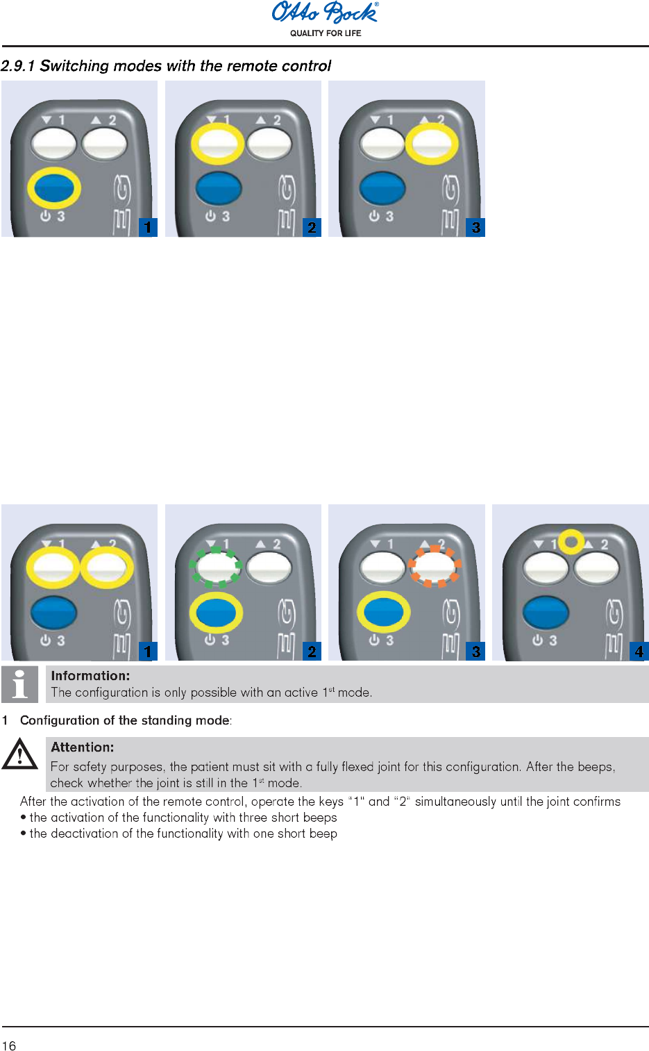
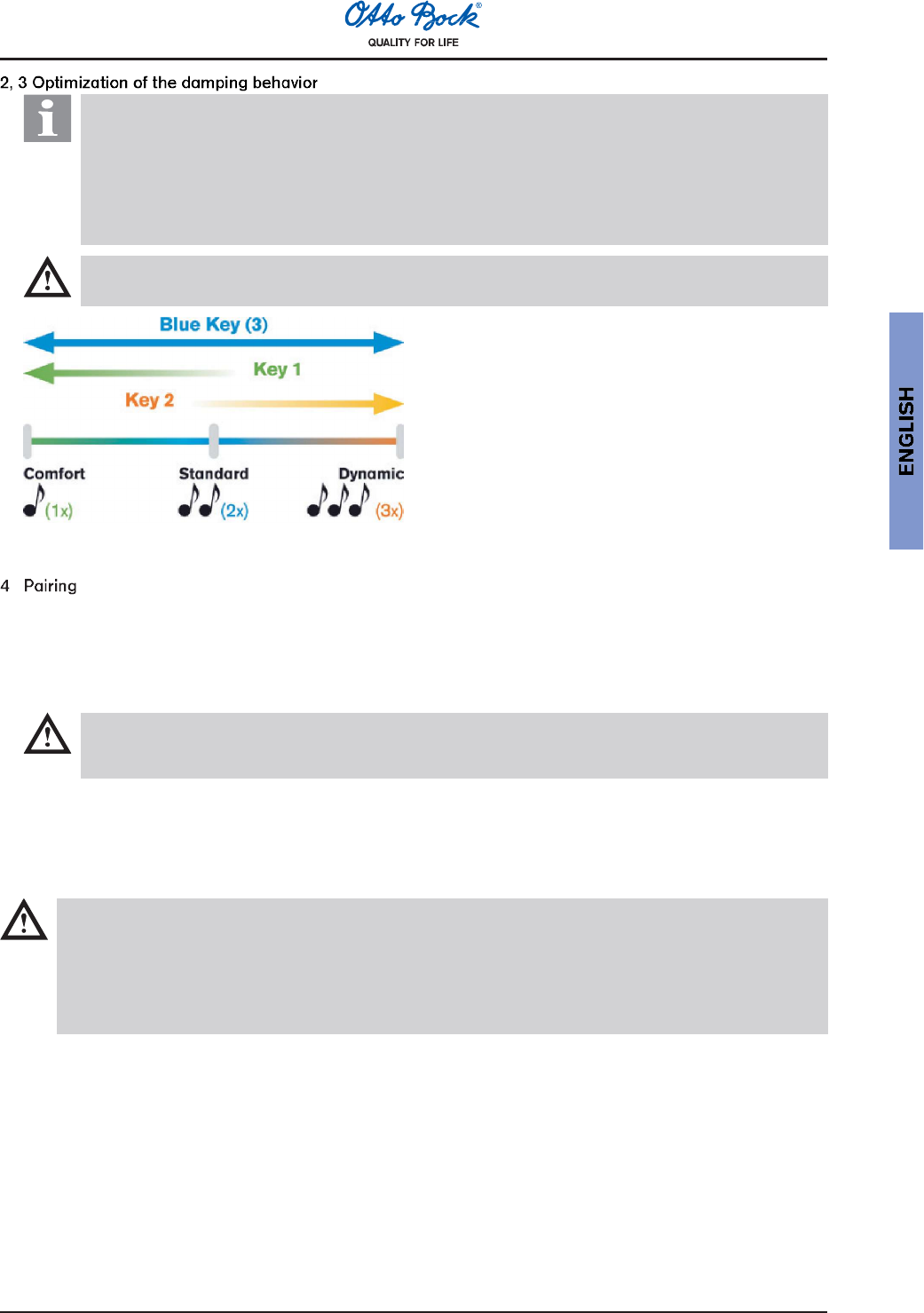
:
Information:
This functionality is not intended for joint adjustment by the prosthetist, who should adjust the joint by
means of the C-Soft (Slider) adjustment software. Rather, this functionality is designed so that the
patient can adapt the damping behavior slightly during everyday use (e.g. when getting used to the
prosthesis or for a changed gait pattern). For safety purposes, the damping behavior can only be
slightly changed with the remote control. Changes to the damping behavior which were effected with
the remote control are not displayed by the C-Soft (Slider).
Attention:
The patient must stand very securely during this procedure.
After activation of the remote control, the selection
steps Comfort - Standard - Dynamic must be set
by pressing key 3 in combination with keys 1 or 2.
The successful setting of the damping parameters
is confirmed acoustically with the following beep
signals:
Comfort = 1x beep signal
Standard = 2x beep signals
Dynamic = 3x beep signals
(Connecting the C-Leg® to the remote control):
Pairing does not have to be performed upon delivery. Pairing must be done
as soon as a new remote control (replacement) is used with the C-Leg®.
if a configuration or mode switch cannot be effected with a fully charged battery of both the joint and the re-
mote control within the working range of the remote control (1 m).
Execution:
Attention:
Given that only one joint can be paired with a remote control, it must be ensured that no other joint is in
the circumference of 3 m during the pairing.
Briefly press the start button by reaching with a thin object (e.g. a paper clip) through the small hole of the re-
mote control. The joint will confirm the successful pairing with 5 short beep signals.
2.9.3 Changing the battery of the remote control
Attention:
The battery of the remote control may only be changed by an authorized Otto Bock Service. The battery is
automatically replaced at the biennial service intervals (see 646A140 C-Leg® Warranty Concept).
To change a battery outside of the biennial service intervals, send the remote control to an authorized
Otto Bock Service. Upon receipt of the remote control with a new battery, the remote control must be
paired with the C-Leg® (see Section 2.9.2).
18
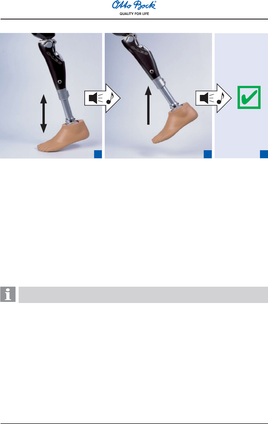
2.9.4 Optional: Switching between 1st mode and 2nd mode without the remote control
21
1 2 3
1 second
3 × in 1
second
1Rock up and down on the forefoot while maintaining continuous ground contact and a speed of at least
3 rocking movements per second (The foot must bear at least 70% of the maximum load. When relieving the
foot, the foot must bear at least 15% of the maximum load).
2Once the acoustic signal beeps, lift the prosthesis for at least one second (no ground contact).
3With further sound signals, the prosthesis acknowledges receipt of the switch command and switches to the
other mode (1st mode = 1 beep signal or 2nd mode = 2 beep signals).
2.10 Finalizing the prosthesis
Upon finalizing all settings, all screws must be fastened and tightened to the proper torque.
1Optional: Remove the cosmetic foam cover (and also the BionicLink, if need be).
2Secure all screws required for the prosthesis alignment (see Section 2.3) with 636K13 Loctite.
3Fasten all screws to the right torque (see Section 2.3) with the 710D4 Torque Wrench.
4Optional: Apply the cosmetic foam cover or the 4X160 C-Leg® Protector.
2.11 Important user instructions
Information:
Advise your patients of the information in this section.
Safety mode
Aside from the operation modes (1st and 2nd mode), the C-Leg® has a safety mode. As soon as a critical error
occurs in the system or when the battery is almost empty, the C-Leg® automatically switches to the safety mode. In
that mode, the prosthesis activates a high flexion damping (high safety/reduced comfort), which enables the patient
to walk safely despite a non-active system.
The switch to the safety mode is announced immediately prior to the switch with sound and vibration signals. If the
safety mode was prompted by an empty battery, recharge the battery. The joint will then switch back automatically
to the operation mode (1st mode).
19
Caution:
Non-active safety mode!
If the C-Leg® does not switch to the safety mode (e.g. due to short-circuit due to water penetration), the
amputee must actively stabilize the C-Leg® at heel strike with his/her residual limb muscles until a prosthetist
can be reached or a prosthesis replacement be accomplished.
Safety mode is activated!
As soon as the sound and vibration signals go off simultaneously, the patient must stop all activities with the
leg prosthesis. After approximately 10 seconds, the patient must check if the safety mode is activated with
the high flexion damping in a safe standing position with repeated slight bending of the C-Leg® and under
controlled weight bearing.
Safety mode cannot be deactivated!
If the safety mode could not be deactivated by recharging the battery, an error has occured. Contact your
prosthetist for troubleshooting.
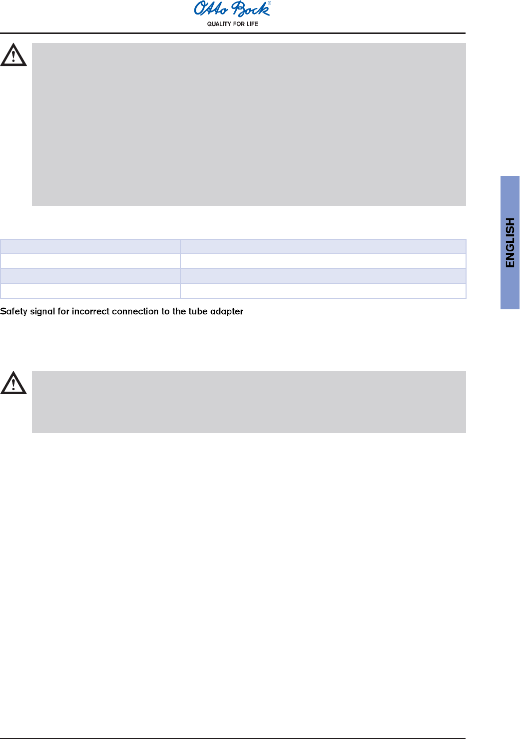
Battery capacity
During normal operation in the 1st and 2nd modes, the battery capacity is indicated with different vibration signals:
Battery capacity Vibration impulse
Approx. 1 hour of operation remains 3×
Approx. 30 min. of operation remains 5×
when turning off 10 ×, then turns off
As soon as the tube adapter has no connection when the C-Leg® is in operation (i.e. 1st, 2nd or standing mode with
sufficient battery capacity), the C-Leg® emits short beeps and, for the duration of approximately five minutes, slowly
pulsing vibration signals. The C-Leg® activates the stance phase damping, which it maintains until the connection of
the tube adapter is properly reset (provided the battery capacity remains sufficient).
Caution:
In the case of such a safety warning, stop any operation of the C-Leg® and resolve the error by properly
connecting the tube adapter (by the prosthetist or service technician).
Insofar as a contact failure has occured between the plug of the tube adapter and the C-Leg® (e.g. following
the fitting by the prosthetist), send the knee joint (incl. tube adapter) to an authorized Otto Bock Service.
Ventilation
After extended non-vertical storage of the C-Leg®, air may accumulate in the hydraulic unit. This is noticeable
through sounds and irregular damping behavior.
The automatic ventilation mechanism ensures that all functions of the C-Leg® are again intact after approximately
10 - 20 steps.
20
3 Additional Information
3.1 Service intervals
To ensure proper function and the safety of the patients, a maintenance service is required every two years. This
service includes the inspection of the sensors and the replacement of worn parts.
To obtain the service, send in the knee joint with mounted C-Leg® tube adapter and remote control as well as the
complete charger unit including the AC adapter.
3.2 Damage event
To simplify problem resolution, describe damage events in detail and document patient statements.
Unless the cause of a damage is very apparent, send in all accessories.
3.3 Technical information
Operating and storage temperature range 0 °C to + 60 °C
Weight of the joint 1145 g
Weight of the 2R80 Tube Adapter 178 g - 256 g
Weight of the 2R81 Tube Adapter 438 g - 482 g
Max. flexion angle 125°
Operating voltage of the battery charger: 90 V - 264 V AC
Operating frequency of the battery charger: 47 Hz - 63 Hz
3.3.1 Symbols on the joint
Declaration of conformity according to the European Directive for Medical Devices 93/42/EEC and
1999/5/EU.
3.3.2 Symbols on the remote control
0681 Declaration of conformity according to the European Directive for Medical Devices 93/42/EEC and
1999/5/EC with the number of the specified authority (0681).
Type BF Applied Part
3.4 Transport
Always use the X-3C100 Shipping Case when transporting your electronic joint system and the 3C88=S/
3C98=S Service Joint.
3.5 Warranty
Otto Bock offers an extensive warranty service on the basis of the current C-Leg® warranty concept (see
646D130). Please comply with the prescribed service intervals (see Section 3.1 Service Intervals). For your own
interest, we also recommend obtaining a confirmation from your patients for the provision of instructions and the
handing over of the device.
21
USA 800-328-4058
Canada 800-665-3327
Great Britain 1784 744 900
3.6 Liability
The device is only to be used under the specified conditions and for the intended purposes. The device must
be maintained according to the Instructions for Use. The device must only be operated with tested modular
components in accordance with the Otto Bock Mobility System. The manufacturer is not liable for damage caused
by component combinations that were not authorized by the manufacturer.
3.7 Declaration of Conformity
Otto Bock Healthcare Products GmbH herewith declares that the electronic 3C88-1/ 3C98-1 C-Leg® Knee Joint
System complies with the basic requirements and the respective provisions of the directives 1999/5/EC and
93/42/EEC. A copy of the declaration of conformity can be requested from the manufacturer (see back side of the
Instructions for Use).


FCC-Statement:
This device complies with part 15 of the FCC Rules. Operation is subject to the following two conditions:
1) This device may not cause harmful interference, and
2) this device must accept any interference received, including interference that may cause undesired
operation. This device and its antenna must not be co-located or operating in conjunction with any other
antenna or transmitter. Modifications not expressly approved by Otto Bock could void the users authority
to operate
the equipment.
Note:
This equipment has been tested and found to comply with the limits for a Class B digital device, pursuant
to part 15 of the FCC Rules. These limits are designed to provide reasonable protection against harmful
interference in a residential installation. This equipment generates, uses and can radiate radio frequency
energy and, if not installed and used in accordance with the instructions, may cause harmful interference
to radio communications. However, there is no guarantee that interference will not occur in a particular in-
stallation. If this equipment does cause harmful interference to radio or television reception, which can be
determined by turning the equipment off and on, the user is encouraged to try to correct the interference
by one or more of the following measures:
Reorient or relocate the receiving antenna.
Increase the separation between the equipment and receiver.
Connect the equipment into an outlet on a circuit different from that to which the receiver is connected.
Consult the dealer or an experienced radio/ TV technician for help.
Patents:
European Patent No. 0 549 855 (B, D, GB, F, I, L, NL, A, P, S, CH, E),
patented in Canada 1991 No. 2 057 108, patented in Russia No. 2 089 138, R.O.C.
Invention Patent No. 076 088,
patented in Japan No. 3 131 933, patented in Korea No. 176 977
Otto Bock Healthcare Products GmbH
Kaiserstraße 39 · 1070 Wien · Austria
Tel. (+43-1) 526 95 48 · Telefax (+43-1) 526 79 85
vertrieb.austria@ottobock.com · www.ottobock.at
Otto Bock has been certified by the German Society for the Certification of Quality Assurance Systems (DQS)
in accordance with DIN EN ISO 9001, Reg. No. 779 (Management System).