Paxton Access 323110 125 kHz Proximity Reader User Manual
Paxton Access Ltd 125 kHz Proximity Reader Users Manual
Contents
- 1. Users Manual
- 2. User manual
- 3. Users manual
Users Manual

Ins-30026-US PROXIMITY P200 & P200 metal mount
Suitability
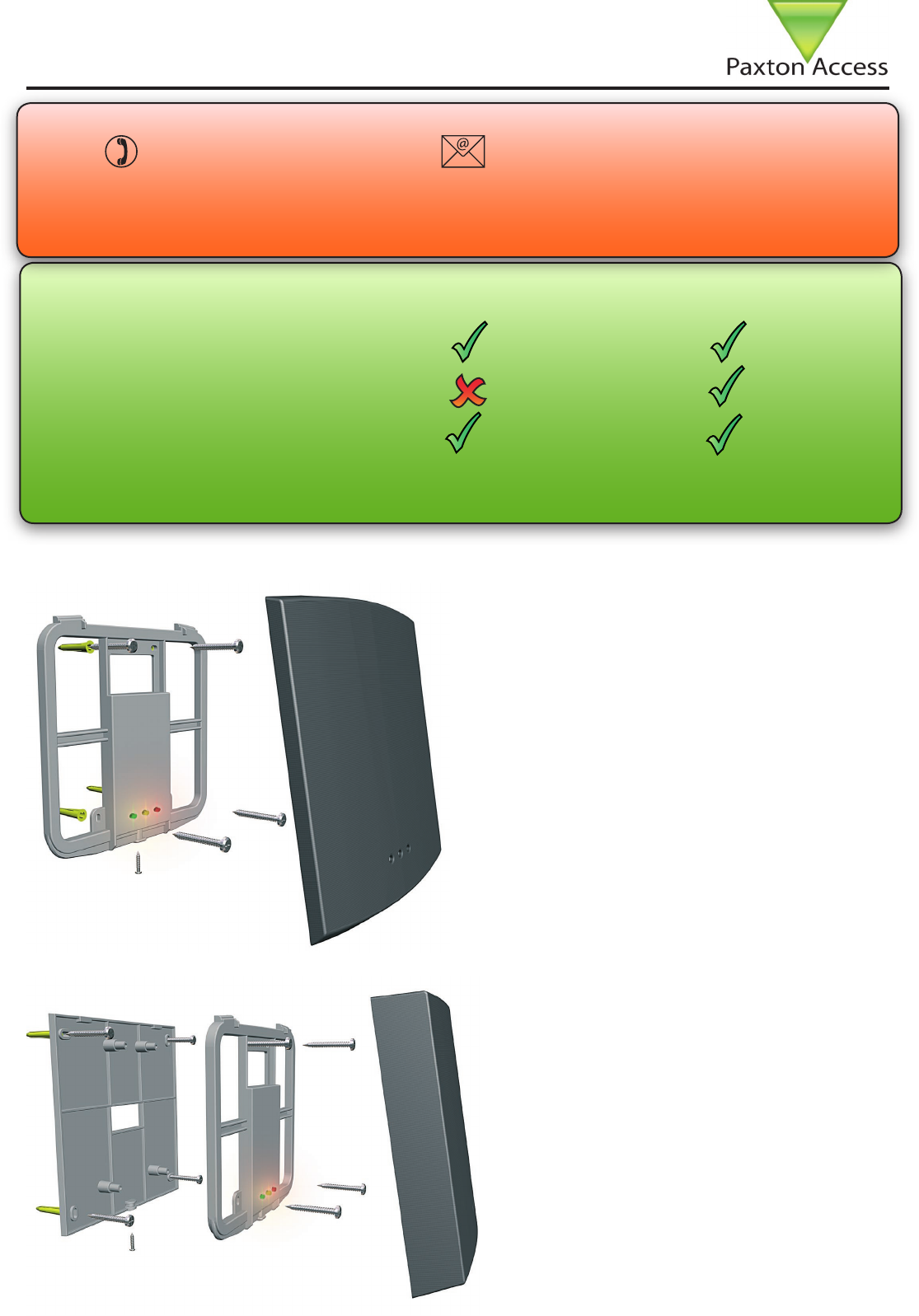
Fitting
03/04/2007
Mounted on metal surface
Security sensitive doors
Wet environments
Readers mounted together
Technical Support
Technical help is available: Monday - Friday from 5am - 5pm PST / 8am - 8pm EST
Other documentation on Net2 can be found on our web site - http://www.paxton-access.com/
1 800 672 PAXT support@paxton-access.co.uk
P200 P200 metal mount
between readers
20 inches
between readers
Reader covers
Additional covers are available in black, white,
grey, blue and silver. Registered installers can
order these free of charge by logging onto the
secure installer extranet: https://extranet.
paxton-access.co.uk/index.asp
If you are not a registered installer please
call us on +44 (0)845 838 1716 for more
information.
20 inches

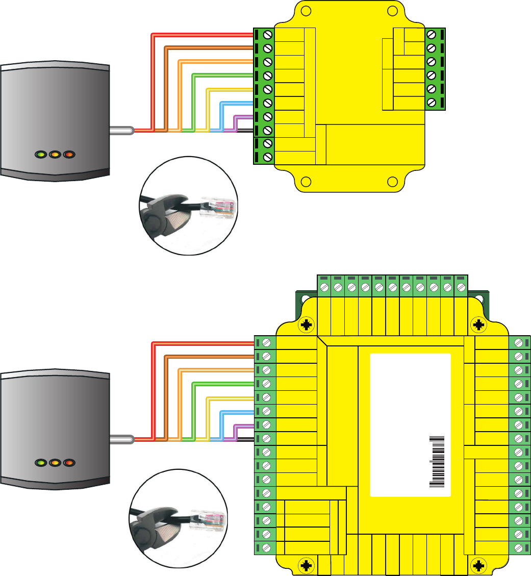
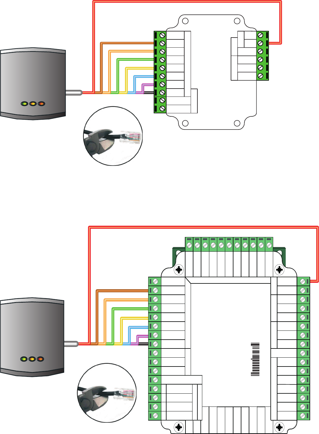
Wiring
Cable extensions
Readers can be extended using Belden CR9540 10-core overall screened cable. The maximum cable length
between reader and control unit is 110 yards.
2EDVDC
"ROWN
/RANGE
'REEN
9ELLOW
"LUE
-AUVE
"LACK7HITE
"ROWN
9ELLOW
2EADER
/RANGE
+EYPAD
V
V
.#
./
#OM
.#
./
#OM
!LARM/UTPUT
V
#ONTACT
V
%XIT
V
4AMPER
035
2X
4X
2ELAY
2ELAY
%XIT
#ONTACT
4AMPER
035
/+
V
V
2ED
"ROWN
/RANGE
'REEN
9ELLOW
"LUE
-AUVE
"LACK7HITE
"ROWN
9ELLOW
/RANGE
2EADER
+EYPAD
0OWER
2ELAY2ELAY)NPUTS
.ETWORK
#!4CABLECODING
7HITE'REEN
'REEN
7HITE/RANGE
/RANGE
3CREENORSPARECORES
FROMNETWORKCABLE
#!54)/.FORVDCREADERSONLY&OR
CORRECTCONNECTIONOFOLDVREADERSREFERTO
INSTRUCTIONS
Serial number
241821
Test ID: 012345678901
z-1440
2ED6
"ROWN
/RANGE
'REEN
9ELLOW
"LUE
-AUVE
%XIT
#ONTACT
"LACK
#ARDREADERORKEYPAD
V
V
.#
./
#OM
"ELL
0OWER$OORRELAY
!LARM
witch
2
S
#ONTROL
UNIT
)NPUTS
CAUTION&OR6DCREADERS
ONLY&ORCORRECTCONNECTIONOFOLD
READERSREFERTOINSTRUCTIONS
Readers used with Net2Air can be extended using Beldon CR9540 10-core overall screened cable. The maximum
cable length between the interface and its Net2 ACU or Switch 2 is 55 yards.
The distance between the reader and the interface should not exceed 15 yards.
The Net2Air interface should not be housed in a metal enclosure.
The range achieved with the interface board will depend greatly on the building’s construction. Trying to position
the interface to avoid large metal objects between the interface and the expected path of users approaching the
door will help.

2ED
"ROWN
/RANGE
'REEN
9ELLOW
"LUE
-AUVE
"LACK7HITE
"ROWN
9ELLOW
2EADER
/RANGE
+EYPAD
V
V
.#
./
#OM
.#
./
#OM
!LARM/UTPUT
V
#ONTACT
V
%XIT
V
4AMPER
035
2X
4X
2ELAY
2ELAY
%XIT
#ONTACT
4AMPER
035
/+
V
V
2ED
"ROWN
/RANGE
'REEN
9ELLOW
"LUE
-AUVE
"LACK7HITE
"ROWN
9ELLOW
/RANGE
2EADER
+EYPAD
0OWER
2ELAY2ELAY)NPUTS
.ETWORK
#!4CABLECODING
7HITE'REEN
'REEN
7HITE/RANGE
/RANGE
3CREENORSPARECORES
FROMNETWORKCABLE
Serial number
241821
Test ID: 012345678901
z-1440
2ED
"ROWN
/RANGE
'REEN
9ELLOW
"LUE
-AUVE
%XIT
#ONTACT
"LACK
#ARDREADERORKEYPAD
V
V
.#
./
#OM
"ELL
0OWER$OORRELAY
!LARM
witch
2
S
#ONTROL
UNIT
)NPUTS

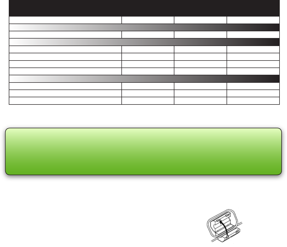
Voltage
Cable length
Clock and data bit period
Carrier frequency
Min Max
-20 °C (-4 °F) +55 °C (+131 °F)
8v DC 14v DC
125 kHz
600 µs
5 yards
Width Height Depth
P200 8” 8” 3/4”
P200E 8” 8” 1 5/8”
Specications
Operating temperatures - all items
Electrical
Environment
Dimensions
FCC Compliance
This device complies with Part 15 of the FCC Rules. Operation is subject to the following two conditions: (1) this
device may not cause harmful interference, and (2) this device must accept any interference received, including
interference that may cause undesired operation.
Changes or modications not expressly approved by the party responsible for compliance
could void the user’s authority to operate the equipment.
The supplied Ferrite clamp must be installed around
the P200 data cable.
This should be tted within 12 inches of the connection
with the door controller.