1000409673 Catalog
1000395593-Catalog 1000395593-Catalog 1000395593-Catalog B5 unilog cesco-content
2016-09-04
: Pdf 1000409673-Catalog 1000409673-Catalog B4 unilog
Open the PDF directly: View PDF ![]() .
.
Page Count: 408 [warning: Documents this large are best viewed by clicking the View PDF Link!]
Contact us
1STC804013D0205 - 11/2015
ABB SACE
A division of ABB S.p.A.
Automation and Distribution Boards
Via Italia, 58
23846 Garbagnate Monastero (LC) - Italy
Tel: +39 031 3570.111
Fax: +39 031 3570.228
www.abb.com
The data and illustrations are not binding. We reserve
the right to modify the contents of this document on
the basis of technical development of the products,
without prior notice.
Copyright 2015 ABB. All right reserved.
Enclosures for Automation
Enclosures for Automation
Technical catalogue | November 2015
Technical catalogue | November 2015

Enclosures for automation
General Catalogue
Introduction
Gemini switchboards
SR2 Enclosures - SR2 EMC Enclosures
AM2 Cabinets
IS2 Enclosures - IS2 EMC Enclosures
C2 Console
Wiring ducts
In-depth technical information
Overall dimensions
Index of codes
ABB Technical catalogue | 1STC804013D0205
11
5
9
3
7
2
6
10
4
8

ABB SACE Division - Quality, ethics and environmental certification
ABB SACE, a division of ABB S.p.A., has always been at the
forefront when it comes to dedicating consistent resources for
the purpose of attaining its sustainability and environmental
protection goals.
A policy confirmed by acquisition of ISO 9001 quality certification
and ISO 14001 environmental management system certification
by all the corporate plants.
The Garbagnate Monastero plant has also obtained certification for its QAS (Quality, Environment,
Safety) integrated management system.
All the corporate divisions have always actively pursued policies for environmental management
improvement implemented by rationalizing the use of raw materials and energy, preventing pollution,
monitoring air and water quality, reducing noise emissions and the waste created by the production
processes as well as conducting regular environmental audits with the major suppliers.
Each of these goals and tasks is the result of a farsighted decision to adopt environmental policies
and methods for reducing environmental impact. Already a leading enterprise as to the quality of its
products, ABB SACE is also a pacesetter in Italy with regard to these issues.
ABB is actively committed to promoting environmental protection and sustainable
development by providing products and solutions that help to improve the energy
efficiency and productivity of the installations while reducing CO2 emissions.
ABB: Energy efficiency for sustainable
progress
Thanks to use of analysis
tools like LCA (Life Cycle
Analysis), assessment
and improvement of the
environmental performance
of the entire life cycle of the
products is included in ABB
SACE's design engineering
work right from the very
start.
This guarantees technical
and energy performance
optimization during
operation and control,
as well as reduction of
environmental impact during
the manufacturing phase
and end of life management
process.

The ABB SACE website: makes your work easier, develops your
business
Technical software Calculation and cost estimate tools
e-Design: everyone has a project, ABB has a solution to
make it happen.
e-Design is the integrated suite, designed and created by ABB, dedicated to designers, technicians,
engineering companies, panel builders and wholesalers. Thanks to e-Design you can design an
electrical installation and optimize the processing time, while benefiting from a product portfolio you
can use in synergy and with intuitive and simple functions.
We would like to highlight several positive features:
FLEXIBILITY
- Interconnected modules accessible during all stages of the project
- Projects that can be reused by all the professionals involved in their creation
VELOCITY
- You can save, duplicate and edit product and switchboard configurations
- Calculation of single-line diagrams and automatic dimensioning of conductors and control and
protection equipment
SIMPLICITY
- You can draw single-line diagrams using predefined macros
- User-friendly configuration of switchboards and products
The software comprises four different modules for different purposes. One single process includes
electrical system dimensioning, selection and configuration of products and accessories, switchboard
configuration and cost estimates. Everything is much easier than in the past. Each individual module
allows you to work on the details, but is also closely connected with the other modules. Using
separate modules, design engineers can make a precise calculation of whole electrical system,
then select equipment to suit the established electrical requirements and create a switchboard
configuration. Finally, if the result is not sufficiently feasible, more detailed calculations can be made
with the switchboard engineering module.
Here are some of the new purpose-made properties that make this process enjoyable:
- Easy drawing of single-line diagrams, both as regards power distribution and command and control
circuits
- Simple and immediate selection and configuration of products, even for those who are not familiar
with ABB products, simply by defining technical features
- The automatic user-friendly design process based on the list of devices simplifies one of the most
complex design stages and avoids compatibility errors between products, assembly kits and
busbar systems
- Effective product organization with tree views, so that the user can work methodically, view the
relevant product immediately and define the switchboards with ease
- Availability of a dedicated module for busbar configuration
Well aware of market requirements, ABB now capitalizes on its experience and presents the new
e-Design suite as a practical answer to every critical aspect of the design process.
The suite’s appealing and brand-
new look, combined with general
optimization of the functions that
have always characterized ABB
software, make it an innovative
tool, up to date with the
technologies currently available
in the sector.
After only a brief introduction,
the user can already design,
calculate, archive and perform
project planning. No special
CAD skills are required. Software
operation is based on dialog
boxes. The user is led through
the program.
e-Design
e-Design suite is structured with
integrated functional modules,
allowing it to support all
planning stages of an electrical
installation. All solutions are
studied in detail, from electrical
network dimensioning, to
switchboard configuration,
through to the final cost estimate
stage.
The registration procedure is
very easy and, once completed,
you can immediately download
installers and upgrades.
- News, to keep you up to date about the latest electrical engineering innovations
- Products, just a simple click for an overview of ABB SACE products 24 hours a day
- Catalogues that you can consult, download and request
- Technical documentation where you can check circuit diagrams, dimensional drawings,
instruction sheets, installation manuals
- Work tools for designing in complete safety
- Training, where you can consult the training catalogue and register for courses online
www.abb.it/lowvoltage
The ABB SACE website will
help you in your daily work with
an innovative approach to the
world of low voltage electrical
installations and industrial
automation.

Among the enterprises belonging to the Group, ABB SACE is in
the forefront when it comes to dedicating consistent resources
to its sustainable development and environmental protection
goals. A policy confirmed by acquisition of ISO 9001 quality
certification and ISO 14001 environmental management system
certification by all the corporate plants as well as Integrated
Quality, Environment, Safety Management System certification
for the majority of business units.
Indeed, all the corporate divisions actively pursue policies for environmental management
improvement implemented by rationalizing the use of raw materials and energy, preventing pollution,
monitoring air and water quality, reducing noise emissions and the waste created by the production
processes as well as conducting regular environmental audits with the major suppliers.
Thanks to use of analysis tools like LCA (Life Cycle Analysis), assessment and improvement of the
environmental performance of the entire life cycle of the products is included in ABB SACE's design
engineering work right from the very start. This with a view to optimizing the technical and energy
performance, controlling and reducing environmental impact during the manufacturing phase and
allowing the product end of life management process to be defined.
ABB SACE Division and its environmental protection commitment
Each of these goals and
tasks is the result of a
farsighted decision to adopt
environmental policies
and methods for reducing
environmental impact.
Already a leading enterprise
as to the quality of its
products, ABB SACE is also
a pacesetter in Italy with
regard to these issues.
ABB dedicates consistent resources for the purpose of attaining its quality and
environmental protection goals, as testified by the following certifications obtained by the
company:
ABB: quality of the certified product

11
ABB Technical catalogue | 1STC804013D0205 1/1
Enclosure for Automation. Great quality, economically unbeatable 1/2
The safety provided by a certified product 1/4
Customized directly in the factory 1/5
Introduction

1
1/2 1STC804013D0205 | Technical catalogue
Enclosure for Automation. Great quality, economically
unbeatable.
A solution for every application
The ABB range of metal structures for automation was conceived and designed based on many years’ experience of working alongside
the major switchboard and machine manufacturers in Italy and on the most highly industrialised and technological world markets.
The metal structures conform to the IEC 62208 and IEC 60439-1 reference Standards and to the new IEC 61439-1-2 Standard.
Their performances are the market reference ones: high IP degrees of protection (according to IEC 60529) and IK (according to IEC
62262), which allow installation in most industrial environments.

11
ABB Technical catalogue | 1STC804013D0205 1/3
Ideal enclosures, special apparatus
Where the new enclosures for automation are the most advanced to be found on the market today, ABB’s automation apparatus is
also a synonym of technological innovation. The enclosures for automation are, of course, integrated with the various ABB control and
operating apparatus, and all the electrical and mechanical values (dissipation, short-time withstand currents, insulation distances, etc.)
have been analysed and checked by the manufacturer. They also offer a high level of preparation for assembly of the apparatus, with
optimised hole drillings, fixings and overall dimensions.
And all this is to save you time!

1
1/4 1STC804013D0205 | Technical catalogue
The safety provided by a certified product.
The law states that all the products must conform to the European Directives and to the reference product Standards, but this is not
enough for ABB. We prefer an external organization to certify the quality of our products, especially with regard to the more critical
aspects, both in technical and application terms.
All the products in the range are also UL approved to satisfy requests from markets where this mark is compulsory.
The technical characteristics and high degree of protection allow their use in environments with a potentially explosive atmosphere.
In fact, the switchgear and enclosures conform to the ATEX 99/92/CE and 94/9/CE Directive (suitable for use in areas 2 and 22).
The IS2 panel board versions dedicated to uses where electromagnetic compatibility (EMC) is required, have also obtained the relative
certification.

11
ABB Technical catalogue | 1STC804013D0205 1/5
Instruction manuals
Detailed multi-language instruction manuals, including drawings, show the correct way to assemble the structures and the components
inside them. User compliance with manufacturer instructions allows the set-up of correctly selected and assembled electrical enclosures
which conform to EN 60439-1 and the new 61439-1-2 (CEI 17/13-1) in accordance with the European Community Low Voltage
Directive (Directive 2006/95/ EC which substitutes 73/23/EEC and subsequent amendments.
Customized directly in the factory.
CUSTOM MADE SERVICE is ABB’s new service for automation metal structures, which, on request, are
supplied painted, drilled and, where necessary, assembled according to the customer’s specific requirements.
All the components in the catalogue marked with the following stamp can use this service.
Painting
A shade of color other than the standard
one (grey orange peel RAL 7035) can be
requested on the mounted versions of the
panel board.
For the various colors/finishes and for details
of the painting cycle characteristics, please
consult page 7/12 of this catalogue.
Customized drilling
CUSTOM MADE SERVICE offers a drilling
service complying with your own specific
drawing, made using CAD dwg or dxf format
drawings. The useful dimensions for
drilling are indicated on page 9/49 and the
following.
Enclosure/Accessories assembly
Should you prefer a solution ready to be
worked, you can choose the Custom Made
Service solution dedicated to battery assembly
of several columns.
The accessories can also be supplied already
factory-mounted by ABB.

2
ABB Technical catalogue | 1STC804013D0205 2/1
Gemini switchboards
General 2/2
Selection of the structure 2/6
Kits for installing apparatus 2/8
Distribution systems 2/10
Ordering codes 2/13
Accessories 2/22
Examples of configurations 2/25

2
2/2 1STC804013D0205 | ABB Technical catalogue
Gemini switchboards
General
ABB SACE’s Gemini range is revolutionizing the market of low
voltage electric insulating switchboards.
The reason for this is that it is the first switchboard made of
thermoplastic material, to which the co-injection molding technique
gives the same mechanical characteristics as polyester.
This means that it is extremely sturdy, with its rigid covering and
In the preparation of insulating panels in low voltage, the Gemini series of ABB ensures
maximum protection and proper operating condition of all equipment modular.
expanded internal core. Moreover, it contains
no fibreglass, a material that with time rises to the surface,
jeopardizing operation and safety of switchboards made og
polyester with which it is usually mixed.
Gemini switchboards have IP66 degree of protection (IP30 with
the door open and with the appropriate components installed) and
Gemini switchboards are made with
co-injection, which ABB SACE is the
first manufacturer in the electric field
to use as a molding technique.
This process obtains a “sandwich”
of two materials with a compact
external covering and an expanded
core, guaranteeing the highest level
of mechanical protection against
impacts (IK10) without the need to
add hardening substances.

To complete the job you can mount the door (reversible and made of insulating
material), which guarantees the degree of protection IP30 when the cabinet door is
opened. There is no need to use tools unless the inner door is not equipped
with buttons, lights etc..
2
ABB Technical catalogue | 1STC804013D0205 2/3
a very high resistance to chemical and atmospheric agents. This
is the reason why Gemini guarantees excellent performances even
in particularly severe operating conditions.
In distribution and mixed applications, the Gemini switchboard
is designed to be fitted with System pro M modular devices and
Tmax moulded-case circuit breakers.
Gemini switchboards are designed to be perfectly compatible
with ABB components for low voltage control and monitoring.
For these applications they can be equipped with modular devices
belonging to the System pro M range, with Tmax moulded-case
circuit-breakers and control and signaling devices, creating a truly
integrated automation system. When deciding the Gemini
layout for control and monitoring applications, not only is it
possible to select the box and door in the required size, but
you can also select the base plate in one of the three versions
in the range. After wiring with the ducts and the Fix-O-Rapid
device, the special standard adjustable feet and hooks must be
fitted onto the base plate, allowing it to be
inserted inside the box at up to seven different depths and three
further levels of adjustment: no tools need to be used to carry
out these operations. To finish the job, the inner door can be
mounted (reversible and made of insulating material),
guaranteeing IP30 degree of protection when the switchboard
door is open. No tools are needed unless the inner door is
equipped with pushbuttons, warning lights, etc.

In compliance with the safety standards, all components of the framework are
applicable on the bottom plate or on the frame without the using any tools.
2
2/4 1STC804013D0205 | ABB Technical catalogue
Application of the inner door
guarantees IP40 degree
of protection when the
switchboard door is open.
The application of the inner
door ensures the degree of
protection IP30 when the
cabinet door is open. The base
plate can be snap-mounted
inside the switchboard.
The fixing hooks and feet
supplied in the standard
versions are applied without
having to use tools, making
it possible to install the base
plate at seven different depths
inside the switchboard. They
can also be adjusted at three
further positions.
Example of a switchboard
configuration for an automation
application: some ABB control
and protection devices are
installed on the plate. The
inner door is fitted with light
signalling devices.
Gemini switchboards
General

2
ABB Technical catalogue | 1STC804013D0205 2/5
Technical characteristics
Compliance with Standards CEI EN 50298, CEI 23-48, CEI 23-49, IEC 60670, CEI EN 60439-1 CEI EN 62208 - IEC 61439-1-2
Rated service voltage Ue 1000 V AC - 1500 V DC
Operating temperature °C -25 °C + 100 °C
Resistance to abnormal heat and fire up to 750 °C
Degree of resistance to impacts IK10 (IEC 62262)
Degree of protection (CEI EN 60529) IP 30 open door
IP 66 closed door
Recyclable 100%
Gemini can be used in any environment, even extreme: it is the first picture in
thermoplastic material with a degree of protection IP66.

(H)
(L)
H
L
(P)
P
150
150
mod.
12/18
24/36
12 mod.
18 mod.
18 mod.
24 mod.
24 mod.
36 mod.
180
300
250
230
450
375
230
600
230
600
330
750
330
900
375 500
500
900
2
2/6 1STC804013D0205 | ABB Technical catalogue
Gemini switchboards
Rapid selection table
Size
No. of
vertical
mod.
H=150mm
No. of DIN
modules
installable
External
dimensions
Internal
dimensions
Complete
switchboard door
Box
Door
Uprights
DIN rail kit
DIN rail+drilled panel
Kit for Tmax
plate+drilled panel Blank panel Modular plate
DIN rail
(H)
mm
(W)
mm
(D)
mm
H
mm
W
mm
D
mm Transparent Opaque
Transparent
Opaque
1 mod.
H=150mm
1+1/2 mod.
H=225mm
1 mod.
H=150mm
2 mod.
H=300mm
1/2 mod.
H=75mm
1 mod.
H=150mm
2 mod.
H=300mm
1 mod.
H=150mm
2 mod.
H=300mm
12 24 (12x2) 400 335 210 300 250 180 1SL0211A00 1SL0201A00 1SL0221A00 1SL0241A00 1SL0231A00 1SL0283A00 1SL0307A00 - - - 1SL0318A00 1SL0324A00 1SL0330A00 1SL0296A00 - 1SL0290A00
23 54 (18x3) 550 460 260 450 375 230 1SL0212A00 1SL0202A00 1SL0222A00 1SL0242A00 1SL0232A00 1SL0284A00 1SL0308A00 1SL0313A00 1SL0336A00 1SL0370A00 1SL0319A00 1SL0325A00 1SL0331A00 1SL0297A00 1SL0302A00 1SL0291A00
34 72 (18x4) 700 460 260 600 375 230 1SL0213A00 1SL0203A00 1SL0223A00 1SL0243A00 1SL0233A00 1SL0285A00 1SL0308A00 1SL0313A00 1SL0336A00 1SL0370A00 1SL0319A00 1SL0325A00 1SL0331A00 1SL0297A00 1SL0302A00 1SL0291A00
44 96 (24x4) 700 580 260 600 500 230 1SL0214A00 1SL0204A00 1SL0224A00 1SL0244A00 1SL0234A00 1SL0285A00 1SL0309A00 1SL0314A00 1SL0337A00 1SL0371A00 1SL0320A00 1SL0326A00 1SL0332A00 1SL0298A00 1SL0303A00 1SL0292A00
55 120 (24x5) 855 585 360 750 500 330 1SL0215A00 1SL0205A00 1SL0225A00 1SL0245A00 1SL0235A00 1SL0286A00 1SL0309A00 1SL0314A00 1SL0337A00 1SL0371A00 1SL0320A00 1SL0326A00 1SL0332A00 1SL0298A00 1SL0303A00 1SL0292A00
66 216 (36x6) 1005 840 360 900 750 330 1SL0216A00 1SL0206A00 1SL0226A00 1SL0246A00 1SL0236A00 1SL0287A00 1SL0310A00 1SL0315A00 1SL0338A00 1SL0372A00 1SL0321A00 1SL0327A00 1SL0333A00 1SL0299A00 1SL0304A00 1SL0293A00
Rapid selection table
Sizes available
Size 1 Size 2 Size 3 Size 4 Size 5 Size 6
Available in 6 different sizes with transparent or opaque door, the Gemini switchboards are suitable for installation in any application
context.

(H)
(L)
H
L
(P)
P
150
150
mod.
12/18
24/36
> Ordering codes page 2/12 > In-depth technical information page 7/1 > Overall dimensions page 9/1
2
ABB Technical catalogue | 1STC804013D0205 2/7
Size
No. of
vertical
mod.
H=150mm
No. of DIN
modules
installable
External
dimensions
Internal
dimensions
Complete
switchboard door
Box
Door
Uprights
DIN rail kit
DIN rail+drilled panel
Kit for Tmax
plate+drilled panel Blank panel Modular plate
DIN rail
(H)
mm
(W)
mm
(D)
mm
H
mm
W
mm
D
mm Transparent Opaque
Transparent
Opaque
1 mod.
H=150mm
1+1/2 mod.
H=225mm
1 mod.
H=150mm
2 mod.
H=300mm
1/2 mod.
H=75mm
1 mod.
H=150mm
2 mod.
H=300mm
1 mod.
H=150mm
2 mod.
H=300mm
12 24 (12x2) 400 335 210 300 250 180 1SL0211A00 1SL0201A00 1SL0221A00 1SL0241A00 1SL0231A00 1SL0283A00 1SL0307A00 - - - 1SL0318A00 1SL0324A00 1SL0330A00 1SL0296A00 - 1SL0290A00
23 54 (18x3) 550 460 260 450 375 230 1SL0212A00 1SL0202A00 1SL0222A00 1SL0242A00 1SL0232A00 1SL0284A00 1SL0308A00 1SL0313A00 1SL0336A00 1SL0370A00 1SL0319A00 1SL0325A00 1SL0331A00 1SL0297A00 1SL0302A00 1SL0291A00
34 72 (18x4) 700 460 260 600 375 230 1SL0213A00 1SL0203A00 1SL0223A00 1SL0243A00 1SL0233A00 1SL0285A00 1SL0308A00 1SL0313A00 1SL0336A00 1SL0370A00 1SL0319A00 1SL0325A00 1SL0331A00 1SL0297A00 1SL0302A00 1SL0291A00
44 96 (24x4) 700 580 260 600 500 230 1SL0214A00 1SL0204A00 1SL0224A00 1SL0244A00 1SL0234A00 1SL0285A00 1SL0309A00 1SL0314A00 1SL0337A00 1SL0371A00 1SL0320A00 1SL0326A00 1SL0332A00 1SL0298A00 1SL0303A00 1SL0292A00
55 120 (24x5) 855 585 360 750 500 330 1SL0215A00 1SL0205A00 1SL0225A00 1SL0245A00 1SL0235A00 1SL0286A00 1SL0309A00 1SL0314A00 1SL0337A00 1SL0371A00 1SL0320A00 1SL0326A00 1SL0332A00 1SL0298A00 1SL0303A00 1SL0292A00
66 216 (36x6) 1005 840 360 900 750 330 1SL0216A00 1SL0206A00 1SL0226A00 1SL0246A00 1SL0236A00 1SL0287A00 1SL0310A00 1SL0315A00 1SL0338A00 1SL0372A00 1SL0321A00 1SL0327A00 1SL0333A00 1SL0299A00 1SL0304A00 1SL0293A00

2
2/8 1STC804013D0205 | ABB Technical catalogue
Gemini switchboards
Rapid selection table
Indications for installation of Tmax moulded-case circuit breakers
The table indicates the type of installation required for the different versions of Tmax moulded-case circuit breakers in Gemini
switchboards. Before carrying out wiring operations, check compliance with Standards on the basis of the technical characteristics of
the switchboard and circuit breaker (CEI 23-51 or CEI EN 60439-1).
Caption
- D, installation on DIN rail
- K1, installation with Tmax kit H = 150 (holes made)
- K2, installation with Tmax kit H = 300 (holes made)
- O1, installation on modular plate (1 module, H = 150 mm)
- O2, installation on modular plate (2 modules, H = 300 mm)
- T, installation on total base plate
Size Installation
T1 T2 T3 T4 T5 XT1 XT2 XT3 XT4
3p 4p 3p D 4p D 3p 4p 3p D 4p D 3p 4p 3p D 4p D 3p 4p 3p D 4p D 3p 4p 3p D 4p D 3p 4p 3p D 4p D 3p 4p 3p D 4p D 3p 4p 3p D 4p D 3p 4p 3p D 4p D
1Dnnnnnnnnnnnn nnnnnnnnnnnnnnnn
O1 nnnnnnnn nnnnnnnnnn nn
Tnnnnnnnnnnnnnn nn nnnnnnnnnnnnnnnn
2Dnnnnnnnnnnnn nnnnnnnnnnnnnnnn
K1 nnnnnnn nnn
K2 nnnnn nnn nnnn
O1 nnnnnnnnnnnnn n nnnnnnnnnnn nnnn
O2 nnnnnnnnnnnnnnnnnn nnnnnnnnnnnnnnnn
Tnnnnnnnnnnnnnnnnnnnnnnnnnnnnnnnnnnnn
3Dnnnnnnnnnnnn nnnnnnnnnnnnnnnn
K1 nnnnnnn nnn
K2 nnnnn nnn nnnn
O1 nnnnnnnnnnnnn n nnnnnnnnnnn nnn
O2 nnnnnnnnnnnnnnnnnn nnnnnnnnnnnnnnnn
Tnnnnnnnnnnnnnnnnnnnnnnnnnnnnnnnnnnnn
4Dnnnnnnnnnnnn nnnnnnnnnnnnnnnn
K1 nnnnnnn nnn
K2 nnnnn nnn nnnn
O1 nnnnnnnnnnnnn n nnnnnnnnnnn nnnn
O2 nnnnnnnnnnnnnnnnnnnnnnnnnnnnnnnnnnnn
Tnnnnnnnnnnnnnnnnnnnnnnnnnnnnnnnnnnnn
5Dnnnnnnnnnnnn nnnnnnnnnnnnnnnn
K1 nnnnnnn nnn
K2 nnnnn nnn nnnn
O1 nnnnnnnnnnnnn n nnnnnnnnnnn nnn
O2 nnnnnnnnnnnnnnnnnnnnnnnnnnnnnnnnnnnn
Tnnnnnnnnnnnnnnnnnnnnnnnnnnnnnnnnnnnn
6Dnnnnnnnnnnnn nnnnnnnnnnnnnnnn
K1 nnnnnnn nnn
K2 nnnnn nnn nnnn
O1 nnnnnnnnnnnnn n nnnnnnnnnnn nnnn
O2 nnnnnnnnnnnnnnnnnnnnnnnnnnnnnnnnnnnn
Tnnnnnnnnnnnnnnnnnnnnnnnnnnnnnnnnnnnn

2
ABB Technical catalogue | 1STC804013D0205 2/9
Horizontal installation
Vertical installation
Fixed circuit-breaker Size
with front terminals No. poles Dimensions H (mm)
Size/Codes
2/3 4/5 6
Tmax T1 03/4 150 1SL0336A00 1SL0337A00 1SL0338A00
Tmax T2 03/4 150 1SL0336A00 1SL0337A00 1SL0338A00
Tmax T2+diff.le 3 300 1SL0370A00 1SL0371A00 1SL0372A00
Tmax T3 03/4 300 1SL0370A00 1SL0371A00 1SL0372A00
Fixed circuit-breaker Size
with front terminals No. poles Dimensions H (mm)
Size/Codes
1 2/3 4/5 6
System Pro M compact modular
apparatus
150 1SL0307A00 1SL0308A00 1SL0309A00 1SL0310A00
225 1SL0313A00 1SL0314A00 1SL0315A00
Tmax T1-T2-T3 3/4 225 1SL0313A00 1SL0314A00 1SL0315A00
Kit for Tmax with pre-drilled holes
Installation on DIN rail

8
12
4
6
> Ordering codes page 2/12 > In-depth technical information page 7/1 > Overall dimensions page 9/1
2
2/10 1STC804013D0205 | ABB Technical catalogue
Gemini switchboards
Kit for installing apparatus
Wiring ducts
Wiring ducts Fix-O-rapid
Base
(mm)
H
(mm)
8-12 mm
Slots
4-6 mm
Slots
Rapid snap-on bases
for DIN rail
Rapid snap-on bases
for plate
15 17 05 019 05 119 - -
25
30 05 033 05 133
05 250 05 270
40 05 043 05 143
60 05 063 05 163
80 05 083 05 183
100 05 094 05 194
40
30 05 035 05 135
05 252 05 272
40 05 045 05 145
60 05 065 05 165
80 05 085 05 185
100 05 095 05 195
60
30 05 037 05 137
05 254 05 274
40 05 047 05 147
60 05 067 05 167
80 05 087 05 187
100 05 096 05 196
80
40 05 049 05 149
05 256 05 276
60 05 069 05 169
80 05 089 05 189
100 05 097 05 197
100
40 05 051 05 151
05 258 05 278
60 05 071 05 171
80 05 091 05 191
100 05 098 05 198
120 40 05 053 05 153 05 260 05 280
80 05 093 05 193
150 100 05 099 05 199 05 262 05 282

> Ordering codes page 2/12 > In-depth technical information page 7/1 > Overall dimensions page 9/1
2
ABB Technical catalogue | 1STC804013D0205 2/11
Distribution systems
Three-poles
Code AD1004 AD1028 AD1029 AD1027
In (A) 125 125 125 160
Icw (kA) 10 4.2 4.2 6.2
Ipk (kA) 24 25 25 20
Version poles 4.2 4 4 4
Installation DIN35/plate DIN35/plate DIN35/plate DIN35
Power supplye Ø cable (mm2) min. 6 6 6 10
max 35 25 with cable terminal 25 with cable terminal 50
No.outgoing feeder (mm2) Ø cable With cable lugs Rigid cable Rigid cable Rigid cable
5L, 4Nx1,5-6mm27x1,5-10mm29x1,5-10mm28x2,25-25mm2
2L, 6Nx4-10mm22x6-25mm22x1,5-16mm21x10-50mm2
1L, 1Nx6-25mm2With cable lugs 2x6-25mm23x16-35mm2
Without cable lugs 7x1,5-10mm2With cable lugs With cable lugs
5L, 4Nx1,5-6mm22x6-16mm22x1,5-6mm28x2,5-16mm2
2L, 6Nx4-10mm2Without cable lugs 9x1,5-10mm23x6-25mm2
1L, 1Nx6-35mm27x2,5-16mm22x6-16mm21x10-35mm2
2x6-35mm2Without cable lugs Without cable lugs
11x2,5-16mm28x6-16mm2
2x6-35mm2 3x6-25mm2
1x10-35mm2
Dimensions HxWxD (mm) 74.5x98x45 93x89x48 96x126x48 90x160.5x50
No. DIN modules 5,5 5 7 9
Rated service voltage Ue (V) 1000 Vac
1500 Vdc
440 440 440
Degree of protection IP 20 20 20 20
(1) possibility of putting in parallel with AD1083 connections.
(2) possibility of putting in parallel with comb type connections (not supplied).
Modular dividers
Single-pole Three-poles
Code AD1076 AD1080(1) AD1007 D1081(2) AD1030 AD1031 AD1075 AD1006
In IEC (A) 125 125 160 160 250 400 125 160
UL (A) 115 115 175 160 230 310 115 175
Icw (kA) 4.4 4.2 11 1.1 21 21 4.4 11
Version pole 1 1 1 1 1 1 3 3
Installation DIN35/plate DIN35/plate DIN35/plate DIN35/plate DIN35/plate DIN35/plate DIN35/plate DIN35/plate
power supply Ø cable (mm2) min. 10 6 16 10 35 95 10 16
max 35 35 70 70 120 185 35 70
No. outgoing feeder Ø cable (mm2) 1,5÷10 4 4
2,5÷16 10 6 10 6 5 5 6 6
2,5÷25 2 2
Dimensions HxWxD (mm) 71x45x42,5 74x27x47 71x45x42,5 92x35x49 95.5x45x49 95.5x45x49 71.5x80x42,5 71.5x80x42,5
No. DIN modules 2,5 1,5 2,5 2 3 3 4.5 4.5
Rated service voltage Ue (V) 1000 Vac
1500 Vdc
1000 Vac
1500 Vdc
1000 Vac
1500 Vdc
1000 Vac
1500 Vdc
1000 Vac
1500 Vdc
1000 Vac
1500 Vdc
1000 Vac
1500 Vdc
1000 Vac
1500 Vdc
Degree of protection IP 20 20 20 20 20 20 20 20
Mark

T
N
T
N
> Ordering codes page 2/12 > In-depth technical information page 7/1 > Overall dimensions page 9/1
Unifix L
Technical characteristics Unifix L
Rated service voltage (Ue)400V AC
Rated insulation voltage (Ui)500V AC
Rated impulse withstand voltage (Uimp) 6kV
Rated frequency 50/60Hz
Rated current (In) central power supply 100A
lateral power supply 80A
Rated short-time withstand current (Icw)
Maximum peak current (Ipk)
Maximum installable circuit-breaker size 100A
Conditioned short-circuit Tmax T1
current (Icc) Tmax T2 N, S
Tmax T3
With circuit-breaker S200 6kA-400V
S200M 10kA-400V
S200P 25kA-400V
Degree of protection IP20
Characteristics of the insulating material Self-extinguishing thermoplastic V1 (UL94)
Characteristics of the conductor material Electrolytic copper
Width
(No. modules/mm)
12/400
18/500
24/600
36/800
Circuit-breaker series Unifix L
SN201
DS201
ED3272 L1/N 40A
ED3280 L2/N 40A
ED3298 L3/N 40A
S200
F200
ED3033 L1 100A
ED3041 L2 100A
ED3058 L3 100A
ED3066 N 100A
F660-F670-S280 (80-100A)
E200 - RS370
ED3132 Power supply L1/L2/L3/N - 350mm
ED0026 Power supply L1/L2/L3/N - 1500mm
ED0025 Power supply L1/L2/L3/N - 2500mm
MDRC - Various apparatus ED3108 Power supply 2 cables L1/N 16A
ED3116 Power supply 3 cables L1/L2/L3 16A
ED3124 Power supply 4 cables L1/L2/L3/N 16A
ED3355 APower supply 2 cables L1/N 40A
ED3363 Power supply 3 cables L1/L2/L3 40A
ED3371 Power supply 42 cables L1/L2/L3/N 71A
For the DDA locks, order the false module ED2845 codes separately
according to the size of the residual current lock
2
2/12 1STC804013D0205 | ABB Technical catalogue
Gemini switchboards
Distribution systems
Connections (L1-L2-L3-N) for System Pro M modular
apparatus.
Power supply of the busbar with 100A feeder module
without cable. Terminal capacity 35mm2.
Direct power supply of the busbars by means of feeder
module.
Power supply by means of modules and cables in
parallel.

> Ordering codes page 2/12 > In-depth technical information page 7/1 > Overall dimensions page 9/1
Ordering codes
Structures without doors
Structures with doors
- Available in 6 sizes
- Single order code combined with box and transparent and opaque door
- Pack with door dismounted and wrapped separately
- Door designed so that it can be hooked onto hinges on both vertical sides and mounted without the use of tools
- To be mounted on the wall using internal holes or fixing brackets supplied as accessories
- Door opening at an angle of more than 180°
- Grey RAL 7035 colour
- Doors supplied with 2 standard double bit locks (3 for sizes 5 and 6) that can be replaced with locks for coded
key or with square/triangular impression (the standard triplex key is suitable for use with three types of impression).
Structure with transparent door
Size
No. vertical
mod.
H=150mm
Useful dimensions
WxHxD (mm) Code
Package/
No. of pieces
1 2 250x300x180 1SL0211A00 1/1
2 3 375x450x230 1SL0212A00 1/1
3 4 375x600x230 1SL0213A00 1/1
4 4 500x600x230 1SL0214A00 1/1
5 5 500x750x330 1SL0215A00 1/1
6 6 750x900x330 1SL0216A00 1/1
Structure with opaque door
Size
No. vertical
mod.
H=150mm
Useful dimensions
WxHxD (mm) Code
Package/
No. of pieces
1 2 250x300x180 1SL0201A00 1/1
2 3 375x450x230 1SL0202A00 1/1
3 4 375x600x230 1SL0203A00 1/1
4 4 500x600x230 1SL0204A00 1/1
5 5 500x750x330 1SL0205A00 1/1
6 6 750x900x330 1SL0206A00 1/1
Size
No. vertical
mod.
H=150mm
Useful dimensions
WxHxD (mm) Code
Package/
No. of pieces
1 2 250x300x180 1SL0221A00 1/1
2 3 375x450x230 1SL0222A00 1/1
3 4 375x600x230 1SL0223A00 1/1
4 4 500x600x230 1SL0224A00 1/1
5 5 500x750x330 1SL0225A00 1/1
6 6 750x900x330 1SL0226A00 1/1
Boxes and doors
2
ABB Technical catalogue | 1STC804013D0205 2/13

Inner doors
- Made of insulating material
- IP30 degree of protection with door open
- Designed so that door can be hinged on both vertical sides
- Snap-on mounting and fixing
Single doors
Structure
Transparent door
Size
No. vertical
mod.
H=150mm
Useful dimensions
WxHxD (mm) Code
Package/
No. of pieces
1 2 250x300x180 1SL0241A00 1/1
2 3 375x450x230 1SL0242A00 1/1
3 4 375x600x230 1SL0243A00 1/1
4 4 500x600x230 1SL0244A00 1/1
5 5 500x750x330 1SL0245A00 1/1
6 6 750x900x330 1SL0246A00 1/1
Opaque door
Size
No. vertical
mod.
H=150mm
Useful dimensions
WxHxD (mm) Code
Package/
No. of pieces
1 2 250x300x180 1SL0231A00 1/1
2 3 375x450x230 1SL0232A00 1/1
3 4 375x600x230 1SL0233A00 1/1
4 4 500x600x230 1SL0234A00 1/1
5 5 500x750x330 1SL0235A00 1/1
6 6 750x900x330 1SL0236A00 1/1
Inner door
Size
No. vertical
mod.
H=150mm
Useful dimensions
WxHxD (mm) Code
Package/
No. of pieces
1 2 250x300x180 1SL0251A00 1/1
2 3 375x450x230 1SL0252A00 1/1
3 4 375x600x230 1SL0253A00 1/1
4 4 500x600x230 1SL0254A00 1/1
5 5 500x750x330 1SL0255A00 1/1
6 6 750x900x330 1SL0256A00 1/1
2
2/14 1STC804013D0205 | ABB Technical catalogue
Gemini switchboards
Ordering codes
> Ordering codes page 2/12 > In-depth technical information page 7/1 > Overall dimensions page 9/1

1SL0307A00
1SL0308A00
1SL0309A00
1SL0310A00
1SL0313A00
1SL0314A00
1SL0315A00
150
225
2
ABB Technical catalogue | 1STC804013D0205 2/15
> Ordering codes page 2/12 > In-depth technical information page 7/1 > Overall dimensions page 9/1
Upright with incorporated wiring duct
Size
Useful dimensions
H (mm) Code
Package/
No. of pieces
1 300 1SL0283A00 1/4
2 450 1SL0284A00 1/4
3 600 1SL0285A00 1/4
4/5 750 1SL0286A00 1/4
6 900 1SL0287A00 1/4
Panel + DIN rail
Size
Panel
Dimensons
W (mm) Code
Package/
No. of pieces
1 module
1 300 1SL0307A00 1/8
2/3 450 1SL0308A00 1/8
4/5 750 1SL0309A00 1/8
6 900 1SL0310A00 1/8
1+1/2 modules
2/3 450 1SL0313A00 1/8
4/5 750 1SL0314A00 1/8
6 900 1SL0315A00 1/8
DIN rail Kit
- Front panel + DIN rail complete with supports for press-on fixing onto uprights and adjustable in depth
- Available in two dimensions - 1 module (H 150 mm) and 1+1/2 module (H 225 mm, sizes 2-6)
- Preset for hinging on the two vertical sides
- Snap-on assembly on the uprights (in conformity with the reference Standards, the panel can only be removed
using a tool)
- Label-holder box for inserting descriptions of the installed apparatus
DIN rail
- Two-sided version
- Supplied with mounting supports that snap onto uprights
- Depth adjustment on uprights
- Designed so that rapid Unifix L mounting bars can be snapped on
DIN rail
Size
No. mod.
horizontal
Dimensions
W (mm) Code
Package/
No. of pieces
1 12 210 1SL0290A00 1/10
2/3 18 318 1SL0291A00 1/10
4/5 24 443 1SL0292A00 1/10
6 36 663 1SL0293A00 1/10
Completion structure
Uprights
- Incorporated vertical wiring duct (ABB patent)
- Snap-on mounting of all components (installation pitch of 75 mm)
- Snap-on insertion into box
- Depth of installed components adjusted at a pitch of 12.5 mm (4 positions for uprights of size 1 and 6
positions for the remaining ones)
- Ergonomic grip to make it easy to insert and extract

1SL0336A00
1SL0337A00
1SL0338A00
1SL0370A00
1SL0371A00
1SL0372A00
150
300
Kit for installing Tmax moulded-case circuit breakers
- For installing Tmax moulded-case circuit breakers in fixed version with front terminals
- Composed of a plate with special drilled holes and a protection panel with vertical slots that can be hinged on
both sides and snap-on mounted (in compliance with reference Standards a tool must be used for removing
the panel)
- Available for sizes 2-6
- Version H 150 with drillings for Tmax T1 3 poles (with and without residual current release), Tmax T1 4 poles
(with and without residual current release), Tmax T2 3 poles (with and without residual current release), Tmax T2
4 poles (without residual current release)
- Version H 300 with drillings for T max T2 4 poles (with residual current release), Tmax T3 3 poles (with and without
residual current release), Tmax T3 4 poles (with and without residual current release)
- Snap-on mounting onto uprights with the possibility of adjusting the plate depth.
To choose the correct kit, see table on page 2/8.
Completion structure
Plate + panel
Size
Dimensions
W (mm) Code
Package/
No. of pieces
1 module H=150mm
2/3 375 1SL0336A00 1/4
4/5 500 1SL0337A00 1/4
6 700 1SL0338A00 1/2
2 modules H=300mm
2/3 375 1SL0370A00 1/4
4/5 500 1SL0371A00 1/4
6 700 1SL0372A00 1/2
2
2/16 1STC804013D0205 | ABB Technical catalogue
Gemini switchboards
Ordering codes
Kit for installing Tmax XT moulded-case circuit breakers
- For installing Tmax moulded-case circuit breakers in fixed version with front terminals
- Composed of a plate with special drilled holes and a protection panel with vertical slots that can be hinged on
both sides and snap-on mounted (in compliance with reference Standards a tool must be used for removing the
panel)
- Available for sizes 2-6
- Snap-on mounting onto uprights with the possibility of adjusting the plate depth
Panel + plate
Size
Dimensions
W (mm) Code
Package/
No. of pieces
1 module H=150mm
2/3 375 1SL0373A00 1/4
4/5 500 1SL0374A00 1/4
6 700 1SL0375A00 1/2
2 modules H=300mm
2/3 375 1SL0376A00 1/4
4/5 500 1SL0377A00 1/4
6 700 1SL0378A00 1/2

1SL0299A00
1SL0296A00
1SL0297A00
1SL0298A00
1SL0302A00
1SL0303A00
1SL0304A00
150
300
Blind front panel
- Available in 1/2 module (H 75 mm), 1 module (H 150 mm) and 2 modules (H 300 mm) dimensions
- H 150 mm and H 300 panels designed to be hinged onto both vertical sides
- Snap-on mounting onto uprights (in compliance with reference Standards a tool must be used for removing the
panel)
Blind front panel
Size
Dimensions
W (mm) Code
Package/
No. of pieces
1/2 module H=75mm
1 250 1SL0318A00 1/10
2/3 375 1SL0319A00 1/10
4/5 500 1SL0320A00 1/6
6 700 1SL0321A00 1/4
1 module H=150mm
1 250 1SL0324A00 1/8
2/3 375 1SL0325A00 1/8
4/5 500 1SL0326A00 1/4
6 700 1SL0327A00 1/4
2 modules H=200mm
1 250 1SL0330A00 1/6
2/3 375 1SL0331A00 1/6
4/5 500 1SL0332A00 1/4
6 700 1SL0333A00 1/4
Completion structure
Partial modular plates
- Available in 1 module (H 150 mm) and 2 module (H 300 mm, sizes 2-6) dimensions
- Snap-on mounting onto uprights with depth adjustment
Modular base plate
Size
Dimensions
W (mm) Code
Package/
No. of pieces
1 module H=150mm
1 210 1SL0296A00 1/6
2/3 318 1SL0297A00 1/4
4/5 443 1SL0298A00 1/4
6 663 1SL0299A00 1/2
2 modules H=300mm
2/3 318 1SL0302A00 1/4
4/5 443 1SL0303A00 1/4
6 663 1SL0304A00 1/2
1SL0318A00
1SL0319A00
1SL0320A00
1SL0321A00
1SL0324A00
1SL0325A00
1SL0326A00
1SL0327A00
1SL0330A00
1SL0331A00
1SL0332A00
1SL0333A00
300
150
75
2
ABB Technical catalogue | 1STC804013D0205 2/17

1SL0353A00
1SL0354A00
1SL0355A00
1SL0356A00
1SL0353A00
1SL0354A00
1SL0355A00
1SL0356A00
Fix-O-Rapid
Rapid mounting device for attaching wiring ducts to the base plate: it snaps onto the plate after drilling a ø 7 mm hole.
Two Fix-O-Rapid devices are enough for each wiring duct section. Fix-O-Rapid guarantees maximum insulation
since it does not involve the use of any metal components inside the wiring duct.
If the wrong wiring duct is selected, it can be dismounted and a version with the same base and a different height
can be attached to the Fix-O-Rapid.
Description Code
Package/
No. of pieces
Rapid mounting device for wiring duct 25mm 05 270 20/600
Rapid mounting device for wiring duct 40mm 05 272 20/600
Rapid mounting device for wiring duct 60mm 05 274 20/600
Rapid mounting device for wiring duct 80mm 05 276 20/240
Rapid mounting device for wiring duct 100mm 05 278 20/240
Rapid mounting device for wiring duct 125mm 05 280 20/240
Rapid mounting device for wiring duct 150mm 05 282 20/240
Completion structure
Wiring kit
- Composed of wiring duct in versions 25x60 mm and 40x60 mm (WxH, 8-12 mm slots) and Fix-O-Rapid device
for the rapid snap-on hooking of the ducts on the DIN rail
- Snap-on mounting on uprights with depth adjustment
Wiring duct + Fix-O-Rapid
Size
Dimensions
W (mm) Code
Package/
No. of pieces
Wiring duct 25x60mm
1 250 1SL0353A00 1/4
2/3 375 1SL0354A00 1/4
4/5 500 1SL0355A00 1/4
6 700 1SL0356A00 1/4
Wiring duct 40x60mm
1 250 1SL0360A00 1/4
2/3 375 1SL0361A00 1/4
4/5 500 1SL0362A00 1/4
6 700 1SL0363A00 1/4
2
2/18 1STC804013D0205 | ABB Technical catalogue
Gemini switchboards
Ordering codes

1SL0259A00
1SL0260A00
1SL0261A00
1SL0262A00
1SL0263A00
1SL0264A00
1SL0275A00
1SL0276A00
1SL0277A00
1SL0278A00
1SL0279A00
1SL0280A00
1SL0267A00
1SL0268A00
1SL0269A00
1SL0270A00
1SL0271A00
1SL0272A00
2
5
2
Base plate
Size
Box dimensions
WxHxD (mm) Code
Package/
No. of pieces
Blank metal
1 250x300x180 1SL0259A00 1/6
2 375x450x230 1SL0260A00 1/6
3 375x600x230 1SL0261A00 1/4
4 500x600x230 1SL0262A00 1/4
5 500x750x330 1SL0263A00 1/4
6 750x900x330 1SL0264A00 1/2
Drilled metal
1 250x300x180 1SL0275A00 1/6
2 375x450x230 1SL0276A00 1/6
3 375x600x230 1SL0277A00 1/4
4 500x600x230 1SL0278A00 1/4
5 500x750x330 1SL0279A00 1/4
6 750x900x330 1SL0280A00 1/2
Insulating material
1 250x300x180 1SL0267A00 1/6
2 375x450x230 1SL0268A00 1/6
3 375x600x230 1SL0269A00 1/4
4 500x600x230 1SL0270A00 1/4
5 500x750x330 1SL0271A00 1/4
6 750x900x330 1SL0272A00 1/2
Base plates
- Available in three versions made of blank or drilled metal and insulating material
- Positioning at 3 different depths for size 1, 4 different depths for sizes 2-3-4 and 7 different depths for sizes 5-6
(adjustments with 30 mm pitch)
- Supplied with feet and hooks adjustable at three further positions (with 7.5 mm pitch)
- Snap-on mounting
- Plates can also be mounted directly on the base with the special kit
Completion structure
Base mounting kit for metal plate
Description Code
Package/
No. of pieces
Base mounting kit for metal
plate 1SL0383A00 1/10
2
ABB Technical catalogue | 1STC804013D0205 2/19

4 poli
N L1 L2 L3
2 poli
N L1
ED3124
ED3132
ED0026
ED0025
350
1500
2500
ED3090
ED3405
ED3413
ED3439
400
600
800
1500
ED3066
ED3041
ED3033
ED3058
ED3104
ED3102
ED3103
ED3101
ED….
2
2/20 1STC804013D0205 | ABB Technical catalogue
Unifix L
Gemini switchboards
Ordering codes
Description
Dimensions
W (mm) Code
Package/
No. of pieces
2-poles busbars
100A 2P 8 module busbar 400 ED2993 1/6
100A 2P 12 module busbar 450 ED3009 1/6
100A 2P 18 module busbar 600 ED3017 1/6
100A 2P 24 module busbar 800 ED3025 1/6
100A 2P 36 module busbar
100A 4P 12 module busbar 400 ED2944 1/6
100A 4P 18 module busbar 450 ED2951 1/6
100A 4P 24 module busbar 600 ED2969 1/6
100A 4P 36 module busbar 800 ED2977 1/6
Connections for various apparatus
Connection with 2 conductors L/N 16A ED3108 1/6
Connection with 3 conductors L1/L2/L3 16A ED3116 1/6
Connection with 4 conductors L1/L2/L3/N 16A
single phase ED3124 1/6
Connection with 2 conductors L1/N 40A ED3355 1/6
Connection with 3 conductors L1/L2/L3 40A ED3363 1/6
Connection with 4 conductors L1/L2/L3/N 40A ED3371 1/6
Connections for apparatus
No.10 connections L1-N 40 A ED3272 1/10
No.10 connections L2-N 40 A ED3280 1/10
No.10 connections L3-N 40 A ED3298 1/10
No.10 connections L 1 100A ED3033 1/10
No.10 connections L 2 100A ED3041 1/10
No.10 connections L 3 100A ED3058 1/10
No.10 connections N 100A ED3066 1/10
Feeder with 4P 100A cable (W=350mm) ED3132 1/1
Feeder with 4P 100A cable (W=1500mm) ED0026 1/1
Feeder with 4P 100A cable (W=1500mm) ED0025 1/1
Power supply modules with cable
Parallel module 2P 100A with cable (W=600mm) ED3082 1/1
Parallel module 4P 100A with cable (W=400mm) ED3405 1/1
Parallel module 4P 100A with cable (W=600mm) ED3090 1/1
Parallel module 4P 100A with cable (W=800mm) ED3413 1/1
Parallel module 4P 100A with cable (W=1500mm) ED3439 1/1
Power supply modules without cable In 100A
No.10 single-pole power supply terminals L1 ED3101 1/10
No.10 single-pole power supply terminals L2 ED3102 1/10
No.10 single-pole power supply terminals L3 ED3103 1/10
No.10 single-pole power supply terminals N ED3104 1/10
Accessories
No.10 busbar covers W=600mm ED2961 1/10
No.2 busbar covers W=800mm ED2962 1/2

1SL0340A00
1SL0339A00
1SL0341A00
1SL0343A00
1SL0344A00
1SL0345A00
1SL0346A00
1SL0352A00
1SL0385A00
1SL0386A00
1SL0387A00
1SL0388A00
1SL0390A00
1SL0458A00 1SL0342A00
2
ABB Technical catalogue | 1STC804013D0205 2/21
Description Code
Package/
No. of piece
Lock with Yale type coded key and handle
1SL0340A00 1/10
Lock with triangular impression
1SL0341A00 1/10
Lock with square impression
1SL0339A00 1/10
Kit for vandalproof closure
1SL0458A00 1/10
Description Code
Package/
No. of piece
(4) horizontal and vertical wall brackets (*)
1SL0342A00 1/10
Pole mounting kit for sizes 1 switchboards
1SL0343A00 1/4
Pole mounting kit for sizes 2-3 switchboards
1SL0344A00 1/4
Pole mounting kit for sizes 4-5 switchboards
1SL0345A00 1/2
Pole mounting kit for size 6 switchboards
1SL0346A00 1/2
Floor mounting pedestal for sizes 1-4
1SL0352A00 1/1
Locks
Available in three versions with ciphered key and handle, with triangular and square impressions.
Mounting elements
Guarantee optimum wall, pole and floor mounting conditions.
Description Code
Package/
No. of piece
Back plugging plate
1SL0342A00 1 1/10
Back plugging plate
1SL0343A00 2 1/4
Back plugging plate
1SL0344A00 3 1/4
Back plugging plate
1SL0345A00 4 1/2
Back plugging plate
1SL0346A00 5 1/2
Back plugging plate
1SL0352A00 6 1/1
Base cover
For aesthetic as well as functional purposes, in particular for pedestal installations.
(*) types of inserts are provided to adapt the ø 6 and 8 mm fixing brackets.

2
2/22 1STC804013D0205 | ABB Technical catalogue
Gemini switchboards
Ordering codes
Size Description Code
Package/
No. of piece
2/3 Vertical coupling kit for sizes 1SL0413A00 1/2
4 Vertical coupling kit for sizes 1SL0414A00 1/2
5 Vertical coupling kit for sizes 1SL0415A00 1/2
6 Vertical coupling kit for sizes 1SL0416A00 1/2
Size Description Code
Package/
No. of piece
2/3 Bottom base 1SL0423A00 1/2
4 Bottom base 1SL0424A00 1/2
5 Bottom base 1SL0425A00 1/2
6 Bottom base 1SL0426A00 1/2
Coupling kit
Follows the aesthetic outline of the boxes. On request, contact ABB for
minimum order quantities.
Bottom base H 30
For fixing the Gemini switchboard directly to the floor.
Accessories
1SL0413A00
1SL0414A00
1SL0415A00
1SL0416A00
1SL0423A00
1SL0424A00
1SL0425A00
1SL0426A00
Size Description Code
Package/
No. of pieces
4 Gemini Pedestal size 4 1SL0464A00 1/1
5 Gemini Pedestal size 5 1SL0465A00 1/1
6 Gemini Pedestal size 6 1SL0466A00 1/1
Pedestal
This enables the Gemini switchboard to be secured to the ground without the need to build plinths or foundations
in cement since it is the pedestal that is buried.

2
ABB Technical catalogue | 1STC804013D0205 2/23
Accessories
Size Description Code
Package/
No. of piece
2/3 Frame for fixing to floor 1SL0433A00 1/2
4 Frame for fixing to floor 1SL0434A00 1/2
5 Frame for fixing to floor 1SL0435A00 1/2
6 Frame for fixing to floor 1SL0436A00 1/2
Fixed frame
In combination with bottom base H 30. For fixing onto poured concrete floors and bases.
1SL0451A00
1SL0452A00
1SL0454A00
1SL0455A00
1SL0456A00
EN0105K
EN0150K
EN0204K
1SL0433A00
1SL0434A00
1SL0435A00
1SL0436A00
Full covers
Description Code
Package/
No. of pieces
Full cover for size 1 switchboards 1SL0451A00 1/1
Full cover for size 2-3 switchboards 1SL0452A00 1/1
Full cover for size 4 switchboards 1SL0454A00 1/1
Full cover for size 5 switchboards 1SL0455A00 1/1
Full cover for size 6 switchboards 1SL0456A00 1/1
Description
Dimensions
WxW (mm) Code
Package/
No. of pieces
Grille + air filter kit 105x105 EN0105K 1/1
Grille + air filter kit
(cannot be used with Size 1 150x150 EN0150K 1/1
Grille + air filter kit
(cannot be used with Size 1 204x204 EN0204K 1/1
Ventilation kit IP21/54
- Composed of plastic grilles (ABS self-extinguishing UL94V0) and filter
- Degree of protection without filter IP21
- Degree of protection with filter IP54
- Equipped with pre-mounted gasket
Screws not included, use 4 self-tapping screws 2.9x13 or order Code 1SL0384A00

2
2/24 1STC804013D0205 | ABB Technical catalogue
Gemini switchboards
Ordering codes
Anti-condensation kit
- Kit made of special material to prevent condensation from forming inside the switchboard: it includes
GORETM MEMBRANE VENTING
- Impermeable to water (pressure): 0.6 bar/60 sec.
- Air flow: 400 ml/min. (dp = 70 mbar)
- 1 kit for sizes 1-2, 2 kits for sizes 3-4 and 3 kits for sizes 5-6 are recommended to guarantee adequate dissipa-
tion. In any case the number of kits to be installed depends on the number and type of devices installed inside
the switchboard.
Description Code
Package/
No. of piece
Anti-condensation kit 1SL0351A00 1/6
Accessories
1SL0351A00
Other accessories
Description Code
Package/
No. of pieces
Universal drill bit 12 849 1/30
Module covers in grey RAL 7035, 4 mo-
dules 12 863 25/300
Deep adapters 12 851 10/80
Small bag containing base plates 1SL0380A00 1/10
Small bag containing DIN supports 1SL0381A00 1/10
Small bag containing partial plate 1SL0382A00 1/10
Small bag containing screws and inserts 1SL0397A00 1/10
Small bag containing ventilation kit fastening
screws 1SL0384A00 10/50
Spare spanner 1SL0457A00 1/10
Description Code
Package/
No. of pieces
Horizontal Gemini Kit size 2 1SL0470A00 1/1
Horizontal Gemini Kit size 3/4 1SL0471A00 1/1
Horizontal Gemini Kit size 5 1SL0472A00 1/1
Horizontal Gemini Kit size 6 1SL0473A00 1/1
Horizontal Gemini kit
Kit to use for opening switchboard upwards in correct manner.

2
ABB Technical catalogue | 1STC804013D0205 2/25
Examples of configurations
Description Code Q.ty
Enclosure + opaque door 1SL0201A00 1
Metal back plate 1SL0259A00 1
Counterdoor 1SL0251A00 1
Wall fixing brackets 1SL0342A00 1
Description Code Q.ty
Enclosure + opaque door 1SL0202A00 1
Metal back plate 1SL0260A00 1
Counterdoor 1SL0252A00 1
Description Code Q.ty
Enclosure + opaque door 1SL0203A00 1
Metal back plate 1SL0269A00 1
Counterdoor 1SL0253A00 1
Wall fixing brackets 1SL0342A00 1
Gemini Switchboard Size 1
Dim. 300x250x180 (400x335x210) mm (external hxwxd) IP66
Gemini Switchboard Size 2
Dim. 450x375x230 (550x460x260) mm (external hxwxd) IP66
Gemini Switchboard Size 3
Dim. 600x375x230 (700x460x260) mm (external hxwxd) IP66

2
2/26 1STC804013D0205 | ABB Technical catalogue
Gemini switchboards
Examples of configurations
Description Code Q.ty
Enclosure + opaque door 1SL0204A00 1
Metal back plate 1SL0262A00 1
Counterdoor 1SL0254A00 1
Kit for fixing to pole 1SL0345A00 1
Description Code Q.ty
Enclosure + opaque door 1SL0205A00 1
Perforated back plate 1SL0279A00 1
Counterdoor 1SL0255A00 1
Wall fixing brackets 1SL0342A00 1
Ventilation Kit 1SL0350A00 1
Description Code Q.ty
Enclosure + opaque door 1SL0206A00 1
Metal back plate 1SL0264A00 1
Counterdoor 1SL0256A00 1
Triangular lock 1SL0341A00 3
Anticondensation Kit 1SL0351A00 3
Gemini Switchboard Size 4
Dim. 600x500x230 (700x590x260) mm (external hxwxd) IP66
Gemini Switchboard Size 5
Dim. 750x500x330 (855x590x360) mm (external hxwxd) IP66
Gemini Switchboard Size 6
Dim. 900x750x330 (1005x840x360) mm (external hxwxd) IP66

3
ABB Technical catalogue 1STC804013D0205 3/1
SR2 - SR2 EMC Enclosures
SR2 Enclosures
General characteristics 3/2
Selection table 3/5
Ordering codes 3/6
SR2 EMC Enclosures
General characteristics and ordering codes 3/22

3
3/2 1STC804013D0205 | ABB Technical catalogue
SR2 Enclosures
General characteristics
The range of SR2 enclosures is a complete offer of monobloc enclosures for
constructing small and medium-sized electric automation, switching and control
switchboards.
The SR2 enclosures come from the experience ABB has gained
over the years in building IP65 metal structures (in accordance
with the IEC 60529 Standard), together with the innovative new
production process used for construction and patented by ABB.
The typical use of SR2 Enclosures is to make switchgear and
controlgear switchboards for a very wide variety of industrial
machines: from large machinery with automated production lines
or parts of these, down to the typical installations of on-board
machine switchboards, boilers, heating plants and so on.
They conform to the EN 62208 Standard “Empty enclosures for
low voltage protection switchgear and controlgear assemblies”
and allow realization of electrical equipment conforming to the
prescriptions of the IEC 60204-1 Standard “Safety of machinery.
Electrical equipment of machines” and of the EN 60439- 1
Standard and the new EN 61439-1-2 Standard “Low voltage
protection switchgear and controlgear for assemblies”. The
degree of protection, in accordance with the IEC 60529 Standard
“Degrees of protection of enclosures (IP Code)”, is IP65.
The SR2 enclosures have also passed the control required to
obtain the UL (Underwriters Laboratories) and CSA (Canadian
Standards Association) Type 12 marks.
The SR2 enclosures also allow secondary distribution
switchboards to be made, thanks to the possibility, in the
400, 600 and 800 mm widths, of installing the whole range of
apparatus and modular circuit-breakers on DIN rails combined
with special pre-drilled and hinged modular front panels, thereby
allowing construction of AS/ANS type electrical switchgear
conforming to the IEC 60439-1 Standard and the new EN
61439-1-2 Standard. A single line of metalwork structures
therefore allows construction of automation and secondary and
end distribution electrical switchboards thanks to the availability
of a series of accessories (modular panels, DIN rails) and to the
possibility of stacking the enclosures.

3
ABB Technical catalogue 1STC804013D0205 3/3
The SR2 enclosures are available in two versions (blind door or glazed door) and in 23
different dimensions, as well as a further 19 combinations obtained by stacking the
enclosures, up to a maximum height of 2000 mm, which guarantee ample selection
possibilities for the various end applications.
The SR2 enclosures have been designed to fulfil all the typical
needs of the builder or installer of switchgear in the best way
possible and the user is presented with a unique ensemble of
functional characteristics:
• wide dimensional range
• certied IP65 degree of protection
• internal galvanised sheet mounting plate with 20/10 thickness
(made to allow threaded holes to be made easily), adjustable in
depth by using a special accessory
• fairlead plate screwed on (at top and bottom) made of 15/10
thick galvanised sheet, with a sealing gasket applied inside
• complete reversibility of the enclosure, so the door can open
either on the right or on the lefthand side
• possibility of installing all the apparatus and modular circuit-
breakers on a DIN rail combined with a hinged modular panel.
The standard colour is RAL 7035 orange peel. On request, the
SR2 enclosures can be ordered in a
wide range of RAL colours (see page 7/12).
Both the enclosures with glazed door or blind door can be
stacked:
stacking is done simply by removing the fairlead plates and
inserting the IP65 sealing gasket (GZ....), made of neoprene with
closed cells.
Assembly of the stacked enclosures is carried out by means of
the same holes used for the fairlead plates.
The door is supplied with the enclosure (single code) so as to
reduce the number of articles and assembly times.

Plastic document pocket, RAL
7035, size A4, the pocket is
apply within the solid doors
wider than 400 mm, with
stickers provided.
Many closure systems can
replace the standard closures
of the external doors.
The inserts are interchangeable
and easily replaced by
loosening a nut.
The brackets for wall mounting
allows installation of the boxes
on the wall using the holes
located on the back of the
enclosure.
The bars, made of electrolytic
copper with M6 threaded holes
in 25 mm, can be mounted
on mounting plates using the
appropriate supports.
3
3/4 1STC804013D0205 | ABB Technical catalogue
SR2 Enclosures
General characteristics
The range is completed with a series of accessories: brackets for wall assembly, rain
shield top cover, locks of various types, internal document pocket, spacers, and spray
paint for touching up. It is possible floor fixing by means plinth.
Technical characteristics
Conformity with Standard IEC 62208, IEC 61439-1-2
Degree of protection IP65 (IEC 60529)
TYPE 12 (Normativa UL)
Degree of mechanical strength IK10 blind door
IK09 glazed door
(IEC 62262)
Certifications
II 3 G D
Type of material Metallic
Installation site Indoors
Fixing method floor/wall
Normal service conditions
- ambient temperature from –5 up to +40°C
Operating climate (t°/Ur%) costant 23°C/83% - 40°C/93%
variable 23°C/98% - 40°C/98%

Overall dimensions Enclosures Kit for automation
Kit for distribution
Supports for mounting modular panels
H
mm
W
mm
D
mm
Enclosures with
blind door +
back plate
with glazed
door *
Blind
counterdoor
Back
plate
No. vertical
mod.
H=185mm
No. DIN mod.
per row
Total
modules
DIN
Supports
300
200
150
SRN3215K
300 SRN3315K
400 SRN3415K
400
300 150 SRN4315K
300
200
SRN4320K
400 SRN4420K
600 SRN4620K
500
300 200 SRN5320K
400 SRN5420K SRN5420VK* KC5040K PF5040 2 14 28 KD5040K
400 250 SRN5425K SRN5425VK* KC5040K PF5040 2 14 28 KD5040K
600 400 200 SRN6420K SRN6420VK* KC6040K PF6040 3 14 42 KD6040K
400 250 SRN6425K SRN6425VK* KC6040K PF6040 3 14 42 KD6040K
600 SRN6625K
700 500 200 SRN7520K SRN7520VK* KC7050K PF7050
500 250 SRN7525K SRN7525VK* KC7050K PF7050
800 600 250 SRN8625K SRN8625VK* KC8060K PF8060 4 25 100 KD8060K
600 300 SRN8630K SRN8630VK* KC8060K PF8060 4 25 100 KD8060K
800 SRN8830K
1000 600 250 SRN10625K SRN10625VK* KC1060K PF1060 5 25 125 KD1060K
600 300 SRN10630K SRN10630VK* KC1060K PF1060 5 25 125 KD1060K
800 SRN10830K SRN10830VK* KC1080K PF1080 5 36 180 KD1080K
1200 600 300 SRN12630K SRN12630VK* KC1260K PF1260 6 25 150 KD1260K
800 SRN12830K SRN12830VK* KC1280K PF1280 6 36 216 KD1280K
DIN mod.
185
185
W D
H
SR2 Enclosures
Selection table
* The mounting plate must be ordered separately.
3
ABB Technical catalogue 1STC804013D0205 3/5
Rapid selection table
> Selection by components page 3/6 > In-depth technical information page 8/1 > Overall dimensions page 9/1

3
3/6 1STC804013D0205 | ABB Technical catalogue
> Rapid selection table page 3/5 > In-depth technical information page 7/1 > Overall dimensions page 9/1
SR2 Enclosures
Ordering codes
3
1
5
8
2
6
4
7
9
11
10
12
13
1
Spray protection roof
Page ....................................................................... 3/6
2
Wall-mounting brackets
Page ..................................................................... 3/11
3
Spacers for back plates
Page ..................................................................... 3/10
4
Blind internal plate
Page ....................................................................... 3/9
5
Slotted internal plate
Page ..................................................................... 3/10
6
Document pocket
Page ..................................................................... 3/16
7
Counterdoor
Page ....................................................................... 3/9
8
Plinth
Page ..................................................................... 3/11
9
Frame for DIN rail
Page ..................................................................... 3/13
10
Modular panels for apparateus
Page ..................................................................... 3/14
11
DIN rail
Page ..................................................................... 3/14
12
Blind modular panels
Page ..................................................................... 3/14
13
Modular panel for DIN rail
Page ..................................................................... 3/14

120°
300
500
600
700
800
120°
1000
1200
3
ABB Technical catalogue 1STC804013D0205 3/7
Enclosures with blind door (internal plate included)
Dimensions (mm)
Code Article
Price
EUR
Package/
No. of piecesH W D
300 (1)
200 150 SRN3215K 1/1
300 150 SRN3315K 1/1
400 150 SRN3415K 1/1
400 (1)
300 150 SRN4315K 1/1
300 200 SRN4320K 1/1
400 200 SRN4420K 1/1
600 200 SRN4620K 1/1
500 (1)
300 200 SRN5320K 1/1
400 200 SRN5420K 1/1
400 250 SRN5425K 1/1
600
400 200 SRN6420K 1/1
400 250 SRN6425K 1/1
600 250 SRN6625K 1/1
700 500 200 SRN7520K 1/1
500 250 SRN7525K 1/1
800
600 250 SRN8625K 1/1
600 300 SRN8630K 1/1
800 300 SRN8830K 1/1
1000*
600 250 SRN10625K 1/1
600 300 SRN10630K 1/1
800 300 SRN10830K 1/1
1200* 600 300 SRN12630K 1/1
800 300 SRN12830K 1/1
SR2 Enclosures with blind door (internal plate included)
The enclosures with blind door, typically for making automation switchgear, are already fitted with the internal
galvanised sheet mounting plate.
(1) The enclosures with height less or egual to 500mm hare only a closing box.
* Plates height 1000 / 1200mm have six mounting points .
> Rapid selection table page 3/5 > In-depth technical information page 7/1 > Overall dimensions page 9/1

120°
3
3/8 1STC804013D0205 | ABB Technical catalogue
SR2 Enclosures
Ordering codes
Enclosures with glazed door
Dimensions (mm)
Code Article
Price
EUR
Package/
No. of piecesH W D
500 (1) 400 200 SRN5420VK 1/1
400 250 SRN5425VK 1/1
600 400 200 SRN6420VK 1/1
400 250 SRN6425VK 1/1
700 500 200 SRN7520VK 1/1
500 250 SRN7525VK 1/1
800 600 250 SRN8625VK 1/1
600 300 SRN8630VK 1/1
1000
600 250 SRN10625VK 1/1
600 300 SRN10630VK 1/1
800 300 SRN10830VK 1/1
1200 600 300 SRN12630VK 1/1
800 300 SRN12830VK 1/1
Enclosures with glazed door
The enclosures with glazed door are also used for distribution configurations. The internal equipment is made,
alternatively, by selecting the special kits:
- KD... (Distribution Kit) consisting of a pair of functional uprights for assembly of the modular panels (to be ordered
separately) and of any compensation panel (see page 2/8).
The modular panels, which can also be installed on the enclosures with blind door with the help of the KD.. kit itself,
are all hinged and have vertical modularity of 185 mm.
(1) The enclosures with height less or egual to 500mm hare only a closing box.
> Rapid selection table page 3/5 > In-depth technical information page 7/1 > Overall dimensions page 9/1

3
ABB Technical catalogue 1STC804013D0205 3/9
Blind counterdoor
Dimensions (mm)
Code
Package/
No. of piecesH W
500 400 KC5040K 1/1
600 400 KC6040K 1/1
700 500 KC7050K 1/1
800 600 KC8060K 1/1
1000 600 KC1060K 1/1
1000 800 KC1080K 1/1
1200 600 KC1260K 1/1
1200 800 KC1280K 1/1
Blind counterdoor
The internal counterdoor guarantees IP20 degree of protection. Made of steel sheet 15/10mm thick, galvanized and
painted orange peel RAL 7035 colour, complete with the EV1008 ergonomic box and insert with double tongue.
Blind back plate for enclosure
Dimensions (mm)
Code
Package/
No. of piecesH W
300 200 PF3020 1/1
300 300 PF3030 1/1
300 400 PF3040 1/1
400 300 PF4030 1/1
400 400 PF4040 1/1
400 600 PF4060 1/1
500 300 PF5030 1/1
500 400 PF5040 1/1
600 400 PF6040 1/1
600 600 PF6060 1/1
700 500 PF7050 1/1
800 600 PF8060 1/1
800 800 PF8080 1/1
1000 600 PF1060 1/1
1000 800 PF1080 1/1
1200 600 PF1260 1/1
1200 800 PF1280 1/1
Blind internal mounting plate
Internal galvanised sheet mounting plate 20/10mm thick complete with fixing with small items provided. Possibility
of adjusting the depth with the help of a special spacer kit (to be ordered separately).
> Rapid selection table page 3/5 > In-depth technical information page 7/1 > Overall dimensions page 9/1
EV1008

3
3/10 1STC804013D0205 | ABB Technical catalogue
SR2 Enclosures
Ordering codes
Slotted internal mounting plate
Fixing with small items provided. Possibility of adjusting the depth with the help of a special spacer kit (to be
ordered separately).
Back plate for enclosure
Dimensions (mm)
Code
Package/
No. of piecesW H
200 300 TQ3020 1/1
300 300 TQ3030 1/1
400 300 TQ3040 1/1
300 400 TQ4030 1/1
400 400 TQ4040 1/1
600 400 TQ4060 1/1
300 500 TQ5030 1/1
400 500 TQ5040 1/1
400 600 TQ6040 1/1
600 600 TQ6060 1/1
500 700 TQ7050 1/1
600 800 TQ8060 1/1
800 800 TQ8080 1/1
600 1000 TQ1060 1/1
800 1000 TQ1080 1/1
600 1200 TQ1260 1/1
800 1200 TQ1280 1/1
Code
Package/
No. of piecesDescription
No.20 clip nuts TQ6610 1/20
Spacer Kit for adjusting the depth of the back plates
Kit consisting of 12 spacers for fixing the back plate with the possibility of adjusting the depth with 25 mm pitch.
Clip nuts
For slotted plates with M6x10mm hexagonal head screws.
Code
Package/
No. of piecesDescription
Spacers 25mm long
25 mm
AA8025 1/12
Spacers 50mm long
50 mm
AA8050 1/12
> Rapid selection table page 3/5 > In-depth technical information page 7/1 > Overall dimensions page 9/1

3
ABB Technical catalogue 1STC804013D0205 3/11
Code
Package/
No. of piecesDescription
Brackets for wall fixing AA1206 1/4
Brackets for wall fixing
These allow wall installation of the enclosures and are mounted by using the special holes positioned on the rear
of the enclosures.
Dimensions (mm)
Code
Package/
No. of piecesW D
IP65 gasket
400 200 GZ4020 1/1
250 GZ4025 1/1
600
200 GZ6020 1/1
250 GZ6025 1/1
300 GZ6030 1/1
800 300 GZ8030 1/1
Accessories for stacking
Plinth
Dimensioni (mm)
Code
Package/
No. of piecesW D H
400 200 100 ZA4020 1/1
250 100 ZA4025 1/1
600 250 100 ZA6025 1/1
300 100 ZA6030 1/1
800 300 100 ZA8030 1/1
Plinth
Steel plinth 25/10 thick grey RAL7012 color.
> Rapid selection table page 3/5 > In-depth technical information page 7/1 > Overall dimensions page 9/1

3
3/12 1STC804013D0205 | ABB Technical catalogue
SR2 Enclosures
Ordering codes
Heater for IP20 electrical switchboards
Their use prevents condensation in the electric cabinets. They consist of a heating element (PTC thermistor) inserted
in an aluminium alloy ground plate. The PTC thermistor is a component which modifies its impedance according to the
operating temperature. It is intrinsically stable and ensures primary safety features for the heater and service stability.
The main qualities of the heaters using PTC are:
- electrical absorption (or dissipated power) which is almost constant in
the range of power supply voltage between 100 and 250V;
- electrical absorption bound by inverse law to the trend of the ambient temperature.
The special tubular geometry of the ground plate allows efficient thermal exchange with the heating element. This
allows high powers and limited overall dimensions (especially in width and depth);
Snap-on assembly on 35 mm DIN rail. Requires a thermostat.
IEC 890 method for calculating the effective cooling surface (CEI 17-43 method)
The total power dissipation P of an enclosure is linked to the exchange effective dissipating surface S, the ∆T
difference between the inner and outer temperature and the k coefficient of heat exchange relative to the material
of the enclosure:
P = k * ΔT * S
k = 5,5 for painted steel
ΔT = T1-T2;
T1 = dew point temperature (on overage 25°C)
T2 = minimum ambient temperature.
Using a SRN8630K box, in “for closed to a wall structures” case we will obtain:
T1 = 25 °C; T2 = 20 °C; K = 5,5; ΔT = (25-20) = 5 °C; S = 1,4m2
The total power dissipation P obtained will be:
P= k * ΔT * S = 38,5 W
The recommended heater is VA7950 (50W).
The exchange surface S can be calculated using the following table taken from the CEI 17-43.
All the heaters with PTC absorb a higher power than the rated one on inrush according to a transitory which lasts
a few tenths of a second.
If the heaters are to be supplied by means of an auxiliary transformer, its apparent power must be sized taking 1.5
times the rated power of the heaters with natural aeration and twice those with forced ventilation into consideration.
Disposition of the cabinet Calculating the enclosure surface S (mm2) Dimensions (m)
Detached, exposed on all sides S = 1,8 x H x (L+P) + 1,4 x L x P
L = width
H = height
P = depth
For closed to a wall structures S = 1,4 x L x (H+P) + 1,8 x P x H
Left or right exposed structure S = 1,4 x P x (H+L) + 1,8 x L x H
Left or right closed to a wall structure S = 1,4 x H x (P+L) + 1,4 x L x P
Central exposed structure S = 1,8 x L x H + 1,4 x L x P + P x H
Central closed to a wall structure S = 1,4 x L x (H+P) + P x H
Central closed to a wall structure, with covered roof S = 1,4 x L x H + 0,7 x L x P + P x H
> Rapid selection table page 3/5 > In-depth technical information page 7/1 > Overall dimensions page 9/1
Detached, exposed on all
sides
For closed to a wall
structures
Left or right exposed
structure
Left or right closed to a
wall structure
Central exposed
structure
Central closed to a wall
structure
Central closed to a wall
structure, with covered roof
Description
Dimensions (mm)
Code
Package/
No. of piecesH W D
Anti-condensation heater 30W,
110-240 Vac-dc 115 42 42 VA7930 1/1
Anti-condensation heater 50W,
110-240 Vac-dcc 165 42 42 VA7950 1/1
Anti-condensation heater 75W,
110-240 Vac-dc 210 42 42 VA7975 1/1
Anti-condensation heater 100W,
110-240 Vac-dc 165 42 51 VA7910 1/1
Anti-condensation heater 150W,
110-240 Vac-dc 146 82 51 VA7915 1/1
Anti-condensation heater with fan
300W, 230 Vac-dc 148 82 91 VA8300 1/1
Temperature management

3
ABB Technical catalogue 1STC804013D0205 3/13
IP20 Thermostat
Conforms to EN 60730-1, CE and cURus standards, IP20 degree of protection. Grey RAL 7035 colour; electrical
life 100,000 cycles. Dimensions (HxWxD) 68x29x45mm, can be mounted on DIN rail. The version with NO (nor-
mally open) contact allows closure of a circuit activating ventilation, air conditioning, or alarms. The version with NC
(normally closed) contact allows opening of a circuit, disconnecting any anti-condensation resistances.
Description
Dimensions (mm)
Code
Package/
No. of piecesH W
Supports 14 mod. DIN x 2 rows
500 400 KD5040K 1/1
Supports 14 mod. DIN x 3 rows 600 400 KD6040K 1/1
Supports 25 mod. DIN x 4
rows
800 600 KD8060K 1/1
Supports 25 mod. DIN x 5
rows
1000 600 KD1060K 1/1
Supports 36 mod. DIN x 5
rows
1000 800 KD1080K 1/1
Supports 25 mod. DIN x 6
rows
1200 600 KD1260K 1/1
Supports 36 mod. DIN x 6
rows
1200 800 KD1280K 1/1
Frame for DIN rail
Internal supports for fixing modular panels and DIN rails, colour RAL 7035 orange peel.
> Rapid selection table page 3/5 > In-depth technical information page 7/1 > Overall dimensions page 9/1
Description
Standard power supply
V~/50-60Hz Code
Package/
No. of pieces
NO ventilation thermostat 12-60 V d.c.; 110-250V a.c. EN0101K 1/1
NC heating thermostat 12-60 V d.c.; 110-250V a.c. EN0102K 1/1
Code
Standard power supply
V~/50-60Hz
Contact capacity Temperature
scale Type of contact WeightLoad Ω Load L
EN0101K 12-60 V d.c.; 110-250V a.c. 10A 2A -10 +80 °C NO 54g
EN0102K 12-60 V d.c.; 110-250V a.c. 10A 2A -10 +80 °C NC 54g
Temperature management

3
3/14 1STC804013D0205 | ABB Technical catalogue
SR2 Enclosures
Ordering codes
Modular panels
Modular panels made of 12/10mm thick sheet steel painted RAL 7035 colour orange peel. The modular hinged
panels can be mounted on the enclosures by using the special kit (KD…) consisting of functional uprights and
compensation panel. The hinges patented by ABB, allow automatic earthing for panel contact when it is closed
and are also prepared for conventional earthing (with a cable). Each modular panel (PM) has a DIN rail provided
(adjustable in depth), the fixing brackets and the relative small items. Modular and circuit-breakers and Tmax
moulded-case circuit-breakers up to T3 can be placed side by side on the same DIN rail using the special depth
adapter AP6001. To install moulded-case circuit-breakers, it is necessary to fix the DIN rail in a position towards
the back. The fixing brackets of the DIN rail allow the wiring duct to be mounted up to a maximum size of 60 x
60 mm.
Modular hinged panels for modular apparatus (DIN rail and fixing brackets included)
Dimensions (mm)
Code
Package/
No. of pieces Description H W
14 mod. DIN + fixing bracket 185 400 PM1414K 1/1
25 mod. DIN + fixing bracket 185 600 PM1625K 1/1
36 mod. DIN + fixing bracket 185 800 PM1836K 1/1
Modular hinged panels for measuring instruments
Dimensions (mm)
Code
Package/
No. of pieces Description H W
2 instruments 72 x 72mm 185 400 PS2476K 1/1
2 instruments 72 x 72mm 185 600 PS2676K 1/1
2 instruments 72 x 72mm 185 800 PS2876K 1/1
Modular hinged blind panels
Dimensions (mm)
Code
Package/
No. of pieces Description H W
Blind panel 185 400 PC1406K 1/1
Blind panel 185 600 PC1606K 1/1
Blind panel 185 800 PC1806K 1/1
Blind panel 370 600 PC2606K 1/1
Blind panel 370 800 PC2806K 1/1
Description
No. of
modules
W
(mm) Code
Package/
No. of pieces
DIN rail and fixing brackets 14 400 GD4006 1/1
DIN rail and fixing brackets 25 600 GD6006 1/1
DIN rail and fixing brackets 36 800 GD8006 1/1
Depth adapter
No.1 depth adapter for Tmax T1-T2-T3-XT1-XT3
W=600mm AP6001 1/4
Description Code
Package/
No. of pieces
Polished flange for XT1 3P mounted on DIN rail AD3301 1/1
Polished flange for XT1 4P mounted on DIN rail AD3302 1/1
Polished flange for XT3 3P mounted on DIN rail AD3303 1/1
Polished flange for XT3 4P mounted on DIN rail AD3304 1/1
DIN rail and fixing brackets
Polished flange for DIN-Rail mounting
Already supplied in the DIN-Rail mounting kit for breakers in MCCBs catalogue
> Rapid selection table page 3/5 > In-depth technical information page 7/1 > Overall dimensions page 9/1
PC….
PS….
PM….
AP6001

3
ABB Technical catalogue 1STC804013D0205 3/15
Neutral or earthing busbars
The busbars, made of electrolytic copper with M6 threaded holes with 25 mm pitch, can be mounted on the
back plates by means of the special supports. They must be sized according to the enclosure and the position
they are installed in.
Door anti-closure device
It can’t be mounted with the inner-door or with modular/blind panels mounted down in structure and hinged.
Description
W
(mm) Code
Package/
No. of pieces
No. 4 busbars sect. 20x5mm 1000 AA8010 1/4
No.5 support for busbar AA8011 1/5
Description Code
Package/
No. of pieces
Door anti-closure device EV0015 1/4
Spray protection roofs
To improve protection against entry of liquids and rain. Made of 15/10mm thick sheet steel, painted RAL 7035
colour orange peel.
Spray protection roof
Dimensions (mm)
Code
Package/
No. of piecesW D
200 150 TT2015K 1/1
300 150 TT3015K 1/1
400 150 TT4015K 1/1
300 200 TT3020K 1/1
400 200 TT4020K 1/1
500 200 TT5020K 1/1
600 200 TT6020K 1/1
400 250 TT4025K 1/1
500 250 TT5025K 1/1
600 250 TT6025K 1/1
600 300 TT6030K 1/1
800 300 TT8030K 1/1
Description
Dimensions (mm)
Code
Package/
No. of piecesH
No. 2 shaped sections for door 600 TS6009 1/2
No. 2 shaped sections for door 700 TS7009 1/2
No. 2 shaped sections for door 800 TS8009 1/2
Shaped sections for accessories
These allow fixing of accessories (e.g. wiring ducts) inside the blind doors. They consist of a pair of vertical cross-
pieces made of 15/10mm thick white galvanised sheet, pre-drilled with 25 mm pitch. In the enclosures with 1000
and 1200 mm height with blind door, the shaped sections are already provided.
> Rapid selection table page 3/5 > In-depth technical information page 7/1 > Overall dimensions page 9/1
AA8011
AA8010

3
3/16 1STC804013D0205 | ABB Technical catalogue
SR2 Enclosures
Ordering codes
> Rapid selection table page 3/5 > In-depth technical information page 7/1 > Overall dimensions page 9/1
Accessories for DIN panel
Code
Package/
No. of piecesDescription
Box Ø 19 mm double tongue and plastic key
(spare part) AA8001 1/1
Box Ø 19 mm with security insert and Yale type
key AA8002 1/1
Box Ø 19 mm with handle and Yale type key AA8003 1/1
Box Ø 19 mm with triangular insert
AA5200 1/1
Plastic key for triangular insert AA5200 AA5190 1/1
Ergonomic box complete with double tongue
insert EV1008 1/1
Single code Yale insert EV1036 1/1
Ronis 455 insert for EV1037 1/1
3mm Double tongue insert EV1039 1/1
Closing systems
These can replace the standard closures of the external doors. The inserts are interchangeable and easily replaced
by loosening a single nut.
Document pocket RAL 7035
Made of plastic, RAL 7035 colour, A4 size. The pocket can be glued inside the blind door with a width of more
than 400 mm, using the adhesives provided.
Description Code
Package/
No. of pieces
Plastic document pocket for A4 EV1075K 1/1
Special Painting Service
Special painting service has to manage with code of enclosure SRN....SPEC ( e.g. SRN4320SPEC VERNSR + note
about color required ). It is necessary specify the color required in the order.
Minimum order quantity 4 pieces.
For any other component or further information, please contact you local sales network.
Code
Package/
No. of piecesDescription
Extra cost for special SR painting VERNSR
AA8001
AA8002
AA8003
EV1008
See page 8/13 for the colours available.
Hole covering strip RAL7035 colour
Description Code
Package/
No. of pieces
No.10 hole covers W=2000mm, grey AD1086 1/10
No.3 hole covers 24 DIN modules W=600mm AD1088 1/3
No.3 hole covers 36 DIN modules W=800mm AD1089 1/3

3
ABB Technical catalogue 1STC804013D0205 3/17
> Rapid selection table page 3/5 > In-depth technical information page 7/1 > Overall dimensions page 9/1
EV1137
EV1135
EV1136
AD1101-AD1102
AD1103-AD1104
EH2118-EH2129
AD1600-AD1800
Description Code
Package/
No. of pieces
No. 10 hinges for panels EH1889 (1) 1/10
No. 5 rapid closures for front panels EH1890 1/5
Hinges and rapid closures for panels
(1) Use No.2 hinges for panel H=150/200/300/400mm, No.3 hinges for panel H=500/600mm.
Etichette scrivibili con sistema Grafoplast compatibile
Description
No. of
DIN mod. Code
Package/
No. of pieces
No. 288 labels 1 DIN mod. 1 AD1101 1/288
No. 192 labels 2 DIN mod. 2 AD1102 1/192
No. 96 labels 3 DIN mod. 3 AD1103 1/96
No. 96 labels 4 DIN mod. 4 AD1104 1/96
Closing plug for instrument holder panels
Description Code
Package/
No. of pieces
No.10 closing plug for instrument holder panels
72x72mm EV1135 1/10
No.5 closing plug for instrument holder panels
96x96mm EV1136 1/5
No.50 tappi di chiusura per pulsanti Ø22mm EV1137 1/50
Adhesive name label holders
Description
Dimensions
(mm)
W Code
Package/
No. of pieces
No. 20 label holders 18 DIN mod 325 EH2118 1/20
No. 20 label holders 29 DIN mod 525 EH2129 1/20
No. 20 label holders 24 DIN mod 432 AD1600 1/20
No. 20 label holders 36 DIN mod 634 AD1800 1/20

3
3/18 1STC804013D0205 | ABB Technical catalogue
SR2 Enclosures
Ordering codes
Description Code
Package/
No. of pieces
No. 100 wiring duct support brackets on upright
structure EV1131 1/100
Wiring duct support brackets
L1
L1
T
L1 L1L3
L1L1L3
L2L2L3
L1 L1 L2
L1 L1 L2
L2 L2 L2
L1 L1 L1
L1 L1 L1
L1 L1 L1
NNN
NNN
NNN
400 VOLT
Ø22
30
47
42
7
> Rapid selection table page 3/5 > In-depth technical information page 7/1 > Overall dimensions page 9/1
Marking
Description Code
Package/
No. of pieces
No.5 adhesive labels ABB-IS2 W=1000mm EV1157 1/5
No.490 adhesive labels Ø 12mm N symbol EV1150 1/490
No.490 adhesive labels Ø 12mm L1symbol EV1151 1/490
No.490 adhesive labels Ø 12mm L2 symbol EV1152 1/490
No.490 adhesive labels Ø 12mm L3 symbol EV1153 1/490
No.490 adhesive labels Ø 12mm T symbol EV1154 1/490
No.10 triangular adhesive labels 125mm with 400V
lightning arrow symbol EV1155 1/10
No.100 triangular adhesive labels 50mm with light-
ning arrow symbol EV1156 1/100
Description Code
Package/
No. of pieces
No.1000 perforating screws 4.2x13mm cross slotted
head EV1100 1/1000
No.1000 perforating screws 4.2x19mm cross slotted
head EV1101 1/1000
No.50 trilobed screws M6 L=10mm AD1033 1/50
Screws for apparatus

3
ABB Technical catalogue 1STC804013D0205 3/19
Code
Package/
No. of piecesDescription
Ergonomic box complete with double tongue insert (without
tongue) EV1008 1/1
N. 10 hings for SR2 enclosures + countersunk rivets AA1204 1/1
N. 16 screws and nuts M6x14 for flange AA1203 1/2
N. 2 fairlead plates for SRN3215K FLN3215K 1/2
N. 2 fairlead plates for SRN3315K-SRN4315K FLN3315K 1/2
N. 2 fairlead plates for SRN3415K FLN3415K 1/2
N. 2 fairlead plates for SRN4320K-SRN5320K FLN4320K 1/2
N. 2 fairlead plates for SRN4420K-SRN5420K-SRN6420K FLN4420K 1/2
N. 2 fairlead plates for SRN5425K-SRN6425K FLN4425K 1/2
N. 2 fairlead plates for SRN4620K FLN4620K 1/2
N. 2 fairlead plates for SRN6625K-SRN8625K-SRN10625K FLN6625K 1/2
N. 2 fairlead plates for SRN7520K FLN7520K 1/2
N. 2 fairlead plates forr SRN7525K FLN7525K 1/2
N. 2 fairlead plates for SRN8630K-SRN10630K-SRN12630K FLN8630K 1/2
N. 2 fairlead plates for SRN8830K-SRN10830-SRN12830K FLN8830K 1/2
Blind door 1000x600mm (hxl) PRN1066K 1/1
Blind door 1000x800mm (hxl) PRN1086K 1/1
Blind door 1200x600mm (hxl) PRN1266K 1/1
Blind door 1200x800mm (hxl) PRN1286K 1/1
Blind door 300x200mm (hxl) PRN3026K 1/1
Blind door 300x300mm (hxl) PRN3006K 1/1
Blind door 300x400mm (hxl) PRN3046K 1/1
Blind door 400x300mm (hxl) PRN4036K 1/1
Blind door 400x400mm (hxl) PRN4046K 1/1
Blind door 400x600mm (hxl) PRN4066K 1/1
Blind door 500x300mm (hxl) PRN5036K 1/1
Blind door 500x400mm (hxl) PRN5046K 1/1
Blind door 600x400mm (hxl) PRN6046K 1/1
Blind door 600x600mm (hxl) PRN6066K 1/1
Blind door 700x500mm (hxl) PRN7056K 1/1
Blind door 800x600mm (hxl) PRN8066K 1/1
Blind door 800x800mm (hxl) PRN8086K 1/1
Glazed door 1000x600mm (hxl) PTN1066K 1/1
Glazed door 1000x800mm (hxl) PTN1086K 1/1
Glazed door 1200x600mm (hxl) PTN1266K 1/1
Glazed door 1200x800mm (hxl) PTN1286K 1/1
Glazed door 500x400mm (hxl) PTN5046K 1/1
Glazed door 600x400mm (hxl) PTN6046K 1/1
Glazed door 700x500mm (hxl) PTN7056K 1/1
Glazed door 800x600mm (hxl) PTN8066K 1/1
Spray paint color grey RAL7035 for structure VB7035 1/1
Spray paint color grey RAL7012 for plinth VB7012 1/1
Spare parts
> Rapid selection table page 3/5 > In-depth technical information page 7/1 > Overall dimensions page 9/1

3
3/20 1STC804013D0205 | ABB Technical catalogue
SR2 Enclosures
Ordering codes
Painting Special Service
Description Code
Package/
No. of pieces
Extra cost for special SR painting VERNSR
Standard size enclosures, standard colour
Special painting service with standard colour (for available colours, see page 8/13) for standard size enclosures
in quantities equal to or greater than 4 units with single code to be managed with code SRN ... SPEC + VERNSR
overprice equal to the number of enclosures + colour note to be specified in the order.
Example: SRN4320SPEC 4
VERNSR 4
COLOUR NOTE
Standard size enclosures, non-standard colour
Request feasibility of implementation by completing the relevant Form for special quotations and send it to the
R&D ECS office.
Management is per offer.
If the offer is accepted and after having received it, it will be possible to place the order with the codes indicated
in the offer with the following features:
Example: SRN4320SPEC 4
VERNSR 4
OFFER REFERENCE IN THE ORDER
Non-standard size enclosures, standard colour
Request feasibility of implementation by completing the relevant Form for special quotations and send it to the
R&D ECS office.
Management is per offer.
If the offer is accepted and after having received it, it will be possible to place the order with the codes indicated
in the offer, that will not be SRN...SPEC, but dummy ones:
Always remember to indicate the offer reference in the order.
Non-standard size enclosures, non-standard colour
Request feasibility of implementation by completing the relevant Form for special quotations and send it to the
R&D ECS office.
Management is per offer.
If the offer is accepted and after having received it, it will be possible to place the order with the codes indicated
in the offer, that will not be SRN...SPEC, but dummy ones:
Always remember to indicate the offer reference in the order.
Please note that the minimum quantity is four pieces with a single code.

3
ABB Technical catalogue 1STC804013D0205 3/21
Special Drilling Service
The overprice amount depends on the number of individual drilled parts and not on the number of holes.
For single part it means: A-door B-plate; C-housing; D-top/bottom part.
Please note that the minimum quantity is 4 pieces with a single code.
The price of the special drilling service depends on the number of parts to be drilled and on the amount of enclo-
sures to be drilled.
Standard size enclosures with special drilling
The special drilling service for standard size enclosures in quantities equal to or greater than 4 units with a single
code has to be managed with code SRN ... SPEC + overprice FORSR/FORSR1/FORSSR2 (see table) equal to the
number of enclosures and the number of parts to be drilled + hole layout to be attached to the order (see useful
drilling areas, page 9/49)
Example: Enclosure (4 pcs) with door to be drilled (1 part)
Example: Enclosure (4 pcs) with door and plate to be drilled (1 parts)
SRN4320SPEC 4
FORSR1 4
DRAWINGS TO BE ATTACHED
Example: Enclosure (4 pcs) with door and plate to be drilled (2 parts)
SRN4320SPEC 4
FORSR1 8
DRAWINGS TO BE ATTACHED
Non-standard enclosure sizes, special drilling
Request feasibility of implementation by completing the relevant Form for special quotations and send it together
with the drill layout to the R&D ECS office.
Management is per offer.
If the offer is accepted and after having received it, it will be possible to place the order with the codes indicated
in the offer, that will not be SRN...SPEC, but dummy ones.
Always remember to indicate the offer reference in the order.
Ricordarsi sempre di indicare nell’ordine il riferimento dell’offerta.
Description Code No. of enclosures to be drilled
Maggiorazione foratura per singola parte forata (A-B-C-D) FORSR1 4-5-6
Maggiorazione foratura per singola parte forata (A-B-C-D) FORSR2 7-8-9
Maggiorazione foratura per singola parte forata (A-B-C-D) FORSR ≥ 10
A
B
C
D
C

3
3/22 1STC804013D0205 | ABB Technical catalogue
Technical characteristics
Conformity with the Standard IEC 62208
Degree of protection IP54 (IEC 60529)
Degree of mechanical strength IK10 blind door
(IEC 62262)
Certifications
TUV
Rheinland
Product Safety
Type of material Metallic
Installation site Indoors
Fixing method floor/wall
Normal service conditions
ambient temperature from –5 up to +40°C
Operating climate (t°/Ur%) costant 23°C/83% - 40°C/93%
variable 23°C/98% - 40°C/98%
The range of SR2 Enclosures EMC (Electromagnetic Compatibility) version has
undergone shielding efficiency tests with success according to the MIL STD 285: 1956
Standard.
This series of products is suitable for making small and medium-
sized electric switchboards for automation, operation and control.
The electromagnetic compatibility problem also requires attention
when selecting enclosures and cabinets.
The increased number of components in the operation and
regulation electronics and the high processing speeds of signals
increasingly often leave a possibility of introducing errors which
can be attributed to electromagnetic interference.
These interferences may be caused continuously, periodically or at
random, from internal or external sources, which generate electric,
magnetic or electromagnetic fields.
SR2 EMC Enclosures
General characteristics and ordering codes
The suitability tests according to MIL STD 285: 1956 (“Attenuation
measurements for enclosures, electromagnetic shielding, for
electronic test purposes, method of”) have confirmed conformity
of the SR2 EMC enclosure with the requirements of the standard.
The attenuation level (measured in dB) remains at high levels for a
wide spectrum of frequencies (from 30MHz to 10GHz).
The SR2 EMC galvanized sheet enclosures are painted externally
with orange peel RAL 7035 colour.
Furthermore, they do not have cable entry flanges on the roof and
on the base.
> In-depth technical information page 7/1 > Overall dimensions page 9/1

120°
3
ABB Technical catalogue 1STC804013D0205 3/23
Ordering codes
Enclosures with blind door and mounting plate
Dimensions (mm)
Code
Package/
No. of piecesH W D
400 600 200 SR4620EMCK 1/1
600 600 250 SR6625EMCK 1/1
1000 800 300 SR10830EMCK 1/1
IP54 - EMC Enclosures with blind door
The enclosures with blind door, typically destined for making automation switchboards, are already provided with
the internal galvanized sheet plate.
For completion of the structure, see accessories on page 3/6
> In-depth technical information page 7/1 > Overall dimensions page 9/1

ABB Technical catalogue | 1STC804013D0205 4/1
4
AM2 Cabinets
General characteristics and applications 4/2
Selection of the structure 4/6
Ordering codes 4/8
Structure 4/10
Mounting plates 4/19
Structures for modular apparatus 4/22
19” rack structures “L” shaped profile 4/28
Accessories 4/29
Spare parts 4/41

4/2 1STC804013D0205 | ABB Technical catalogue
4
AM2 Cabinets
General characteristics and applications
The range of AM2 cabinets allows construction of electric switchboards for operation
and control of technological plants, covering the middle market segment of automation
switchboards in particular.
These monobloc enclosures are suitable for making floor-
mounted electric switchboards, offering numerous customization
possibilities based on individual needs and habits.
The AM2 cabinets, within the range of ABB automation
enclosures, take an intermediate position in terms of dimensions,
functions and price, in between the SR2 enclosures and the IS2
cabinets, offering a unique ensemble of technical characteristics,
along with simplicity of assembly.
Versions available
- Panel board with blind door (single for W ≤1000mm, double with overlapping closure for W≤800mm);
- Panel board with glazed door;
- Panel board with 19” fixed rack frame “L” shaped profile;
- Distribution cabinet with DIN rails and panels.
The range of AM2 cabinets is available with 36 different dimensions:
- Height from 1000 to 2000mm
- Width from 600 to 1600mm (the cabinets with width ≥ 1200mm are only supply at the front with double door)
- Depth 300, 400 and 500mm
- Two different versions: with blind door and with glazed door.
600 - 800 - 1000
1000 - 1200 - 1400 - 1600 - 1800 - 2000
600 - 800 - 1000 300 - 400 - 500800 -1000 -1200 1600

ABB Technical catalogue | 1STC804013D0205 4/3
4
The AM2 cabinets can also be installed in environments with risk of explosion due to
the presence of dust (ATEX), as foreseen under the European 94/9 CE directive and
from the relative EN 50281-3 Standard.
The full compliance with the IEC 62208 Standards (Empty
enclosures for low voltage switchgear and controlgear assemblies)
and the relative technical characteristics, allow use of the AM2
cabinets in the most varied application contexts, as prescribed
by the IEC 60204-1 Standard on electrical equipment, “Safety of
electrical equipment of machines”, by the EN 60439-1 Standard
and by the new EN 61439-1-2 Standard on “Low voltage
switchgear and controlgear assemblies”.
The whole range of AM2 cabinets is characterised by its IP65
degree of protection, tested and verified according to the EN
60529 Standard. AM2 cabinets have also passed the checks
required to obtain the TYPE 12 UL marks (Underwriters
Laboratories).
Impact resistance is in conformity with the IEC 62262 Standard
and is IK10 for the versions with blind doors and IK09 for those
with glass doors. The standard colour is orange peel RAL 7035.
On request, it is possible to order the AM2 cabinets in a wide
range of RAL colours (see page 7/12) and to use the mounted
accessories service.
The above-mentioned versatility features are such as to allow the
use of AM2 cabinets as switchgear and controlgear of industrial
processing machines and plants, air conditioning plants, up to
application such as distribution switchboards for plants, buildings
etc.

4/4 1STC804013D0205 | ABB Technical catalogue
4
Briefly, the main technical and functional characteristics of the AM2 cabinets and their
components are as follows:
AM2 Cabinets
General characteristics and applications
Structure
- Made of steel sheet 15/10mm thick automatically welded by means of a robot, M6
pins for earthing applied inside.
- IP65 degree of protection verified according to the IEC60529 Standard.
- Mounting plate in galvanized sheet 25/10mm thick and such as to therefore guarantee
protection even of the parts drilled by the user; the plate is adjustable in depth with a
pitch of 25mm.
Assembly of the plates in the cabinets height-wise is facilitated by the presence of two
sliding supports at the back of the cabinet.
Cable tightening plates and plinth
- The cable tightening plates, not included in the supply, are of the sliding type, fitted
with tightness gasket all depth.
- Palletisable plinths consisting of h=100mm four angle pieces already fixed onto the
base of the structure. The four closing flanges must be ordered separately
Door
- Front doors with 120° opening made of steel sheet 15/10mm thick, with internal
polyurethane foam gasket, laid using a continuous casting process.
The blind doors are fitted with an internal tube section which increases the rigidity and
allows easy assembly of wiring ducts and accessories.
The version with glazed doors are fitted with hardened safety glass 4mm thick glued
from the outside and such as to guarantee the IP65 degree of protection. Standard
opening is from the left to right with the possibility of only inverting the direction of the
handle.
- Lock with double tongue insert and hooking device from two (h=1400mm) to four
(h=1600-1800-2000mm) closing points.
- The versions with h=1000 and 1200mm are fitted with two closing points by means of
a box with double tongue key.
- Screwed rear panel, made of 15/10mm thick steel sheet, removable and replaceable
with a door.
- Internal counterdoor made of 15/10mm thick painted sheet, fixed onto a pair of internal
uprights and positioned at a distance of 50mm from the external front door

ABB Technical catalogue | 1STC804013D0205 4/5
4
Distribution switchboard
- The AM2 cabinets can be fitted with modular panels in 600 and 800mm widths made
of 15/10mm thick steel sheet as accessories. The modular panels are available in
the version with DIN cut-out for one or three rows of modular apparatus, in the blind
version and for 72x72mm and 96x96mm measuring instruments.
All the panels have vertical modularity of 200mm and are available in fixed or hinged
version (by means of an accessory).
The panels with 600mm wide DIN cut-out, allow installation of 18 or 24 DIN modules,
whereas those 800mm wide, allow installation of 29 or 36 DIN modules, according to
whether the wiring duct is placed to the front or to the back in relation to the DIN rail.
Installation of the modular panels in the AM2 cabinets requires the use of special
uprights for modular panels which are screwed onto the cabinet structure.
The useful space for installation of the modular panels is always 100mm less than
the nominal dimension of the cabinet. The DIN rails are ordered separately and the kit
includes the rail, the supports and the small fixing items. Finally, the modular galvanized
internal plates are available in the 600 and 800mm widths and in the heights from 200
to 800mm. The modular plates are fixed using a kit of side crosspieces to be ordered
separately according to the depth of the cabinet.
Panel board with 19” rack frame with “L” shaped profile
- Uprights with sections for mounting 19” rack panels and accessories are available
for the whole range of AM2 cabinets; this allows various electronic applications or is
suitable for making small cabinets for local networks (LAN).
The 19” rack uprights with “L” shaped profile are made of 20/10mm thick galvanized
sheet and are applied to the structure of the AM2 cabinets 600mm wide by means of
special screws: they are available for all the AM2 cabinet heights, up to a maximum of
42 HE vertical modules.
The buffer panels are available in the dimensions up to 20 HE modules, are blind and
are made of natural opaque colour anodized aluminium 30/10mm thick.
Technical characteristics
Conformity with Standard IEC 62208, IEC 60439-1, IEC 61439-1-2
Degree of protection IP65 (IEC 60529)
TYPE 12 (UL Standard)
Degree of mechanical strength IK10 blind door
IK09 glazed door
(IEC 62262)
Certifications
II 3 G D
Type of material Metallic
Installation site Indoors
Fixing method floor/wall
Normal service conditions
- ambient temperature from –5 up to +40°C
Operating climate (t°/Ur%) costant 23°C/83% - 40°C/93%
variable 23°C/98% - 40°C/98%

Dimensioni di ingombro Armadio con porta cieca Armadio con porta vetro Flange ingresso cavi Flange zoccolo Piastre interne Controporta Montanti guida DIN Telai rack 19”
H (*)
mm
L
mm
P
mm Porta cieca singola
Porta cieca doppia
chiusa in battuta Porta vetro singola Fisse Scorrevoli fronte/retro fianco Piastra di montaggio Piastra contrapposta
Colore
RAL7035 bucciato
1000
600 300 TM2063K EF6032 ZE6000 ZE3011 EA1060 EA5060 TF1060K MD1000 TK1000
800 TM2083K TM2083FV4K EF8032 EZ8000 EA1080 EA5082 TF1080K MD1000
1000 TM2003FV5K EF1032 ZE1000 EA1010 EA5010 TF1010K
600 400 TM2064K TM2064VK EF6043 EF6040 ZE6000 ZE4011 EA1060 EA5060 TF1060K MD1000 TK1000
800 TM2084K TM2084FV4K TM2084VK EF8042 EF8040 ZE8000 EA1080 EA5082 TF1080K MD1000
1000 TM2004K TM2004FV5K EF1042 EF1040 ZE1000 EA1010 EA5010 TF1010K
1200 TM2024K 2 x EF6043 2 x EF6040 ZE1200 EA1012
1600 TM2074K 2 x EF8042 2 x EF8040 2 x ZE8000 EA1016
1200
600 300 TM2263K EF6032 ZE6000 ZE3011 EA1260 EA5260 TF1260K MD1200 TK1200
800 TM2283FV4K EF8032 ZE8000 EA1280 EA5280 TF1280K MD1200
1200 TM2223K 2 x EF6032 ZE1200 EA1213
600 400 TM2264K TM2264VK EF6043 EF6040 ZE6000 ZE4011 EA1260 EA5260 TF1260K MD1200 TK1200
800 TM2284K TM2284VK EF8042 EF8040 ZE8000 EA1280 EA5280 TF1280K MD1200
1000 TM2204K TM2204FV5K TM2204VK EF1042 EF1040 ZE1000 EA1210 EA5210 TF1210K
1200 TM2224K 2 x EF6043 2 x EF6040 ZE1200 EA1213
1400
600 300 TM2463K EF6032 ZE6000 ZE3011 EA1460 EA5461 TF1460K MD1400 TK1400
800 TM2483K TM2483FV4K TM2483VK EF8032 ZE8000 EA1480 EA5480 TF1480K MD1400
1000 TM2403K EF1032 ZE1000 EA1411 EA5413 TF1410K
600 400 TM2464K TM2464VK EF6043 EF6040 ZE6000 ZE4011 EA1460 EA5461 TF1460K MD1400 TK1400
800 TM2484K TM2484FV4K TM2484VK EF8042 EF8040 ZE8000 EA1480 EA5480 TF1480K MD1400
1000 TM2404K TM2404FV5K TM2404VK EF1042 EF1040 ZE1000 EA1411 EA5413 TF1410K
1200 TM2424K 2 x EF6043 2 x EF6040 ZE1200 EA1412
600 500 TM2465K EF6052 EF6050 ZE6000 ZE5011 EA1460 EA5461 TF1460K MD1400 TK1400
800 TM2485K TM2485FV4K EF8052 EF8050 ZE8000 EA1480 EA5480 TF1480K MD1400
1000 TM2405K TM2405FV5K EF1052 EF1053 ZE1000 EA1411 EA5413 TF1410K
1200 TM2425K 2 x EF6052 2 x EF6050 ZE1200 EA1412
1600
600 300 TM2663K EF6032 ZE6000 ZE3011 EA1616 EA5616 TF1660K MD1600 TK1600
800 TM2683K EF8032 ZE8000 EA1619 EA5620 TF1680K MD1600
600 400 TM2664K TM2664VK EF6043 EF6040 ZE6000 ZE4011 EA1616 EA5616 TF1660K MD1600 TK1600
800 TM2684K TM2684FV4K TM2684VK EF8042 EF8040 ZE8000 EA1619 EA5620 TF1680K MD1600
1000 TM2604K TM2604FV5K TM2604VK EF1042 EF1040 ZE1000 EA1610 EA5610 TF1610K
1200 TM2624K 2 x EF6043 2 x EF6040 ZE1200 EA1612
600 500 TM2665K EF6052 EF6050 ZE6000 ZE5011 EA1616 EA5616 TF1660K MD1600 TK1600
800 TM2685K TM2685FV4K EF8052 EF8050 ZE8000 EA1619 EA5620 TF1680K MD1600
1000 TM2605K TM2605FV5K EF1052 EF1053 ZE1000 EA1610 EA5610 TF1610K
1200 TM2625K 2 x EF6052 2 x EF6050 ZE1200 EA1612
1800
600 400 TM2864K TM2864VK EF6043 EF6040 ZE6000 ZE4011 EA1860 EA5861 TF1860K MD1800 TK1800
800 TM2884K TM2884FV4K TM2884VK EF8042 EF8040 ZE8000 EA1880 EA5883 TF1880K MD1800
1000 TM2804K TM2804FV5K TM2804VK EF1042 EF1040 ZE1000 EA1810 EA5811 TF1810K
1200 TM2824K 2 x EF6043 2 x EF6040 ZE1200 EA1812
600 500 TM2865K TM2865VK EF6052 EF6050 ZE6000 ZE5011 EA1860 EA5861 TF1860K MD1800 TK1800
800 TM2885K TM2885VK EF8052 EF8050 ZE8000 EA1880 EA5883 TF1880K MD1800
1000 TM2805K TM2805VK EF1052 EF1053 ZE1000 EA1810 EA5811 TF1810K
1200 TM2825K 2 x EF6052 2 x EF6050 ZE1200 EA1812
2000
600 400 TM2964K TM2964VK EF6043 EF6040 ZE6000 ZE4011 EA2060 EA5063 TF2060K MD2000 TK2000
800 TM2984K TM2984VK EF8042 EF8040 ZE8000 EA2080 EA5083 TF2080K MD2000
1000 TM2904K TM2904FV5K TM2904VK EF1042 EF1040 ZE1000 EA2010 EA5011 TF2010K
1200 TM2924K 2 x EF6043 2 x EF6040 ZE1200 EA2013
2000
600 500 TM2965K TM2965VK EF6052 EF6050 ZE6000 ZE5011 EA2060 EA5063 TF2060K MD2000 TK2000
800 TM2985K TM2985VK EF8052 EF8050 ZE8000 EA2080 EA5083 TF2080K MD2000
1000 TM2905K TM2905VK EF1052 EF1053 ZE1000 EA2010 EA5011 TF2010K
1200 TM2925K 2 x EF6052 2 x EF6050 ZE1200 EA2013
100
H
D
W
1400/1600/1800/2000
1000/1200
400-500
Depth Depth
300
4/6 1STC804013D0205 | ABB Technical catalogue
4
AM2 Cabinets
Selection of the structure
Rapid selection table
Overall dimensions Cabinet with blind door Cabinet with glazed door Cable entry flanges Plinth Flanges Internal plate Counterdoor DIN rail Uprights
19” rack frames “L”
shaped profile
H (*)
mm
W
mm
D
mm Single blind door
Double blind door with
overlapping closure Single glazed door Fixed Sliding front/rear side Mounting plate Opposed plate
RAL7035 orange
peel colour
1000
600
300
TM2063K EF6032N ZN6000 ZN3011 EA1060 EA5060 TF1060K MD1000 TK1000
800 TM2083K TM2083FV4K EF8032N ZN8000 EA1080 EA5082 TF1080K MD1000
1000 TM2003FV5K EF1032N ZN1000 EA1010 EA5010 TF1010K
600
400
TM2064K TM2064VK EF6043 EF6040 ZN6000 ZN4011 EA1060 EA5060 TF1060K MD1000 TK1000
800 TM2084K TM2084FV4K TM2084VK EF8042 EF8040 ZN8000 EA1080 EA5082 TF1080K MD1000
1000 TM2004K TM2004FV5K EF1042 EF1040 ZN1000 EA1010 EA5010 TF1010K
1200 TM2024K 2 x EF6043 2 x EF6040 ZN1200 EA1012
1600 TM2074K 2 x EF8042 2 x EF8040 2 x ZN8000 EA1016
1200
600
300
TM2263K EF6032N ZN6000 ZN3011 EA1260 EA5260 TF1260K MD1200 TK1200
800 TM2283FV4K EF8032N ZN8000 EA1280 EA5280 TF1280K MD1200
1200 TM2223K 2 x EF6032N ZN1200 EA1213
600
400
TM2264K TM2264VK EF6043 EF6040 ZN6000 ZN4011 EA1260 EA5260 TF1260K MD1200 TK1200
800 TM2284K TM2284VK EF8042 EF8040 ZN8000 EA1280 EA5280 TF1280K MD1200
1000 TM2204K TM2204FV5K TM2204VK EF1042 EF1040 ZN1000 EA1210 EA5210 TF1210K
1200 TM2224K 2 x EF6043 2 x EF6040 ZN1200 EA1213
1400
600
300
TM2463K EF6032N ZN6000 ZN3011 EA1460 EA5461 TF1460K MD1400 TK1400
800 TM2483K TM2483FV4K TM2483VK EF8032N ZN8000 EA1480 EA5480 TF1480K MD1400
1000 TM2403K EF1032N ZN1000 EA1411 EA5413 TF1410K
600
400
TM2464K TM2464VK EF6043 EF6040 ZN6000 ZN4011 EA1460 EA5461 TF1460K MD1400 TK1400
800 TM2484K TM2484FV4K TM2484VK EF8042 EF8040 ZN8000 EA1480 EA5480 TF1480K MD1400
1000 TM2404K TM2404FV5K TM2404VK EF1042 EF1040 ZN1000 EA1411 EA5413 TF1410K
1200 TM2424K 2 x EF6043 2 x EF6040 ZN1200 EA1412
600
500
TM2465K EF6052 EF6050 ZN6000 ZN5011 EA1460 EA5461 TF1460K MD1400 TK1400
800 TM2485K TM2485FV4K EF8052 EF8050 ZN8000 EA1480 EA5480 TF1480K MD1400
1000 TM2405K TM2405FV5K EF1052 EF1053 ZN1000 EA1411 EA5413 TF1410K
1200 TM2425K 2 x EF6052 2 x EF6050 ZN1200 EA1412
1600
600 300 TM2663K EF6032N ZN6000 ZN3011 EA1616 EA5616 TF1660K MD1600 TK1600
800 TM2683K EF8032N ZN8000 EA1619 EA5620 TF1680K MD1600
600
400
TM2664K TM2664VK EF6043 EF6040 ZN6000 ZN4011 EA1616 EA5616 TF1660K MD1600 TK1600
800 TM2684K TM2684FV4K TM2684VK EF8042 EF8040 ZN8000 EA1619 EA5620 TF1680K MD1600
1000 TM2604K TM2604FV5K TM2604VK EF1042 EF1040 ZN1000 EA1610 EA5610 TF1610K
1200 TM2624K 2 x EF6043 2 x EF6040 ZN1200 EA1612
600
500
TM2665K EF6052 EF6050 ZN6000 ZN5011 EA1616 EA5616 TF1660K MD1600 TK1600
800 TM2685K TM2685FV4K EF8052 EF8050 ZN8000 EA1619 EA5620 TF1680K MD1600
1000 TM2605K TM2605FV5K EF1052 EF1053 ZN1000 EA1610 EA5610 TF1610K
1200 TM2625K 2 x EF6052 2 x EF6050 ZN1200 EA1612
1800
600
400
TM2864K TM2864VK EF6043 EF6040 ZN6000 ZN4011 EA1860 EA5861 TF1860K MD1800 TK1800
800 TM2884K TM2884FV4K TM2884VK EF8042 EF8040 ZN8000 EA1880 EA5883 TF1880K MD1800
1000 TM2804K TM2804FV5K TM2804VK EF1042 EF1040 ZN1000 EA1810 EA5811 TF1810K
1200 TM2824K 2 x EF6043 2 x EF6040 ZN1200 EA1812
600
500
TM2865K TM2865VK EF6052 EF6050 ZN6000 ZN5011 EA1860 EA5861 TF1860K MD1800 TK1800
800 TM2885K TM2885VK EF8052 EF8050 ZN8000 EA1880 EA5883 TF1880K MD1800
1000 TM2805K TM2805VK EF1052 EF1053 ZN1000 EA1810 EA5811 TF1810K
1200 TM2825K 2 x EF6052 2 x EF6050 ZN1200 EA1812
2000
600
400
TM2964K TM2964VK EF6043 EF6040 ZN6000 ZN4011 EA2060 EA5063 TF2060K MD2000 TK2000
800 TM2984K TM2984VK EF8042 EF8040 ZN8000 EA2080 EA5083 TF2080K MD2000
1000 TM2904K TM2904FV5K TM2904VK EF1042 EF1040 ZN1000 EA2010 EA5011 TF2010K
1200 TM2924K 2 x EF6043 2 x EF6040 ZN1200 EA2013
2000
600
500
TM2965K TM2965VK EF6052 EF6050 ZN6000 ZN5011 EA2060 EA5063 TF2060K MD2000 TK2000
800 TM2985K TM2985VK EF8052 EF8050 ZN8000 EA2080 EA5083 TF2080K MD2000
1000 TM2905K TM2905VK EF1052 EF1053 ZN1000 EA2010 EA5011 TF2010K
1200 TM2925K 2 x EF6052 2 x EF6050 ZN1200 EA2013
(*) The useful height is always less than 100mm compared to the external dimension of the panel board to which the plinth dimension (H=100mm) must be added.

Dimensioni di ingombro Armadio con porta cieca Armadio con porta vetro Flange ingresso cavi Flange zoccolo Piastre interne Controporta Montanti guida DIN Telai rack 19”
H (*)
mm
L
mm
P
mm Porta cieca singola
Porta cieca doppia
chiusa in battuta Porta vetro singola Fisse Scorrevoli fronte/retro fianco Piastra di montaggio Piastra contrapposta
Colore
RAL7035 bucciato
1000
600 300 TM2063K EF6032 ZE6000 ZE3011 EA1060 EA5060 TF1060K MD1000 TK1000
800 TM2083K TM2083FV4K EF8032 EZ8000 EA1080 EA5082 TF1080K MD1000
1000 TM2003FV5K EF1032 ZE1000 EA1010 EA5010 TF1010K
600 400 TM2064K TM2064VK EF6043 EF6040 ZE6000 ZE4011 EA1060 EA5060 TF1060K MD1000 TK1000
800 TM2084K TM2084FV4K TM2084VK EF8042 EF8040 ZE8000 EA1080 EA5082 TF1080K MD1000
1000 TM2004K TM2004FV5K EF1042 EF1040 ZE1000 EA1010 EA5010 TF1010K
1200 TM2024K 2 x EF6043 2 x EF6040 ZE1200 EA1012
1600 TM2074K 2 x EF8042 2 x EF8040 2 x ZE8000 EA1016
1200
600 300 TM2263K EF6032 ZE6000 ZE3011 EA1260 EA5260 TF1260K MD1200 TK1200
800 TM2283FV4K EF8032 ZE8000 EA1280 EA5280 TF1280K MD1200
1200 TM2223K 2 x EF6032 ZE1200 EA1213
600 400 TM2264K TM2264VK EF6043 EF6040 ZE6000 ZE4011 EA1260 EA5260 TF1260K MD1200 TK1200
800 TM2284K TM2284VK EF8042 EF8040 ZE8000 EA1280 EA5280 TF1280K MD1200
1000 TM2204K TM2204FV5K TM2204VK EF1042 EF1040 ZE1000 EA1210 EA5210 TF1210K
1200 TM2224K 2 x EF6043 2 x EF6040 ZE1200 EA1213
1400
600 300 TM2463K EF6032 ZE6000 ZE3011 EA1460 EA5461 TF1460K MD1400 TK1400
800 TM2483K TM2483FV4K TM2483VK EF8032 ZE8000 EA1480 EA5480 TF1480K MD1400
1000 TM2403K EF1032 ZE1000 EA1411 EA5413 TF1410K
600 400 TM2464K TM2464VK EF6043 EF6040 ZE6000 ZE4011 EA1460 EA5461 TF1460K MD1400 TK1400
800 TM2484K TM2484FV4K TM2484VK EF8042 EF8040 ZE8000 EA1480 EA5480 TF1480K MD1400
1000 TM2404K TM2404FV5K TM2404VK EF1042 EF1040 ZE1000 EA1411 EA5413 TF1410K
1200 TM2424K 2 x EF6043 2 x EF6040 ZE1200 EA1412
600 500 TM2465K EF6052 EF6050 ZE6000 ZE5011 EA1460 EA5461 TF1460K MD1400 TK1400
800 TM2485K TM2485FV4K EF8052 EF8050 ZE8000 EA1480 EA5480 TF1480K MD1400
1000 TM2405K TM2405FV5K EF1052 EF1053 ZE1000 EA1411 EA5413 TF1410K
1200 TM2425K 2 x EF6052 2 x EF6050 ZE1200 EA1412
1600
600 300 TM2663K EF6032 ZE6000 ZE3011 EA1616 EA5616 TF1660K MD1600 TK1600
800 TM2683K EF8032 ZE8000 EA1619 EA5620 TF1680K MD1600
600 400 TM2664K TM2664VK EF6043 EF6040 ZE6000 ZE4011 EA1616 EA5616 TF1660K MD1600 TK1600
800 TM2684K TM2684FV4K TM2684VK EF8042 EF8040 ZE8000 EA1619 EA5620 TF1680K MD1600
1000 TM2604K TM2604FV5K TM2604VK EF1042 EF1040 ZE1000 EA1610 EA5610 TF1610K
1200 TM2624K 2 x EF6043 2 x EF6040 ZE1200 EA1612
600 500 TM2665K EF6052 EF6050 ZE6000 ZE5011 EA1616 EA5616 TF1660K MD1600 TK1600
800 TM2685K TM2685FV4K EF8052 EF8050 ZE8000 EA1619 EA5620 TF1680K MD1600
1000 TM2605K TM2605FV5K EF1052 EF1053 ZE1000 EA1610 EA5610 TF1610K
1200 TM2625K 2 x EF6052 2 x EF6050 ZE1200 EA1612
1800
600 400 TM2864K TM2864VK EF6043 EF6040 ZE6000 ZE4011 EA1860 EA5861 TF1860K MD1800 TK1800
800 TM2884K TM2884FV4K TM2884VK EF8042 EF8040 ZE8000 EA1880 EA5883 TF1880K MD1800
1000 TM2804K TM2804FV5K TM2804VK EF1042 EF1040 ZE1000 EA1810 EA5811 TF1810K
1200 TM2824K 2 x EF6043 2 x EF6040 ZE1200 EA1812
600 500 TM2865K TM2865VK EF6052 EF6050 ZE6000 ZE5011 EA1860 EA5861 TF1860K MD1800 TK1800
800 TM2885K TM2885VK EF8052 EF8050 ZE8000 EA1880 EA5883 TF1880K MD1800
1000 TM2805K TM2805VK EF1052 EF1053 ZE1000 EA1810 EA5811 TF1810K
1200 TM2825K 2 x EF6052 2 x EF6050 ZE1200 EA1812
2000
600 400 TM2964K TM2964VK EF6043 EF6040 ZE6000 ZE4011 EA2060 EA5063 TF2060K MD2000 TK2000
800 TM2984K TM2984VK EF8042 EF8040 ZE8000 EA2080 EA5083 TF2080K MD2000
1000 TM2904K TM2904FV5K TM2904VK EF1042 EF1040 ZE1000 EA2010 EA5011 TF2010K
1200 TM2924K 2 x EF6043 2 x EF6040 ZE1200 EA2013
2000
600 500 TM2965K TM2965VK EF6052 EF6050 ZE6000 ZE5011 EA2060 EA5063 TF2060K MD2000 TK2000
800 TM2985K TM2985VK EF8052 EF8050 ZE8000 EA2080 EA5083 TF2080K MD2000
1000 TM2905K TM2905VK EF1052 EF1053 ZE1000 EA2010 EA5011 TF2010K
1200 TM2925K 2 x EF6052 2 x EF6050 ZE1200 EA2013
100
H
D
W
1400/1600/1800/2000
1000/1200
400-500
Depth Depth
300
ABB Technical catalogue | 1STC804013D0205 4/7
4
> Ordering code page 4/8 > In-depth technical information page 8/1 > Overall dimensions page 9/1
Overall dimensions Cabinet with blind door Cabinet with glazed door Cable entry flanges Plinth Flanges Internal plate Counterdoor DIN rail Uprights
19” rack frames “L”
shaped profile
H (*)
mm
W
mm
D
mm Single blind door
Double blind door with
overlapping closure Single glazed door Fixed Sliding front/rear side Mounting plate Opposed plate
RAL7035 orange
peel colour
1000
600
300
TM2063K EF6032N ZN6000 ZN3011 EA1060 EA5060 TF1060K MD1000 TK1000
800 TM2083K TM2083FV4K EF8032N ZN8000 EA1080 EA5082 TF1080K MD1000
1000 TM2003FV5K EF1032N ZN1000 EA1010 EA5010 TF1010K
600
400
TM2064K TM2064VK EF6043 EF6040 ZN6000 ZN4011 EA1060 EA5060 TF1060K MD1000 TK1000
800 TM2084K TM2084FV4K TM2084VK EF8042 EF8040 ZN8000 EA1080 EA5082 TF1080K MD1000
1000 TM2004K TM2004FV5K EF1042 EF1040 ZN1000 EA1010 EA5010 TF1010K
1200 TM2024K 2 x EF6043 2 x EF6040 ZN1200 EA1012
1600 TM2074K 2 x EF8042 2 x EF8040 2 x ZN8000 EA1016
1200
600
300
TM2263K EF6032N ZN6000 ZN3011 EA1260 EA5260 TF1260K MD1200 TK1200
800 TM2283FV4K EF8032N ZN8000 EA1280 EA5280 TF1280K MD1200
1200 TM2223K 2 x EF6032N ZN1200 EA1213
600
400
TM2264K TM2264VK EF6043 EF6040 ZN6000 ZN4011 EA1260 EA5260 TF1260K MD1200 TK1200
800 TM2284K TM2284VK EF8042 EF8040 ZN8000 EA1280 EA5280 TF1280K MD1200
1000 TM2204K TM2204FV5K TM2204VK EF1042 EF1040 ZN1000 EA1210 EA5210 TF1210K
1200 TM2224K 2 x EF6043 2 x EF6040 ZN1200 EA1213
1400
600
300
TM2463K EF6032N ZN6000 ZN3011 EA1460 EA5461 TF1460K MD1400 TK1400
800 TM2483K TM2483FV4K TM2483VK EF8032N ZN8000 EA1480 EA5480 TF1480K MD1400
1000 TM2403K EF1032N ZN1000 EA1411 EA5413 TF1410K
600
400
TM2464K TM2464VK EF6043 EF6040 ZN6000 ZN4011 EA1460 EA5461 TF1460K MD1400 TK1400
800 TM2484K TM2484FV4K TM2484VK EF8042 EF8040 ZN8000 EA1480 EA5480 TF1480K MD1400
1000 TM2404K TM2404FV5K TM2404VK EF1042 EF1040 ZN1000 EA1411 EA5413 TF1410K
1200 TM2424K 2 x EF6043 2 x EF6040 ZN1200 EA1412
600
500
TM2465K EF6052 EF6050 ZN6000 ZN5011 EA1460 EA5461 TF1460K MD1400 TK1400
800 TM2485K TM2485FV4K EF8052 EF8050 ZN8000 EA1480 EA5480 TF1480K MD1400
1000 TM2405K TM2405FV5K EF1052 EF1053 ZN1000 EA1411 EA5413 TF1410K
1200 TM2425K 2 x EF6052 2 x EF6050 ZN1200 EA1412
1600
600 300 TM2663K EF6032N ZN6000 ZN3011 EA1616 EA5616 TF1660K MD1600 TK1600
800 TM2683K EF8032N ZN8000 EA1619 EA5620 TF1680K MD1600
600
400
TM2664K TM2664VK EF6043 EF6040 ZN6000 ZN4011 EA1616 EA5616 TF1660K MD1600 TK1600
800 TM2684K TM2684FV4K TM2684VK EF8042 EF8040 ZN8000 EA1619 EA5620 TF1680K MD1600
1000 TM2604K TM2604FV5K TM2604VK EF1042 EF1040 ZN1000 EA1610 EA5610 TF1610K
1200 TM2624K 2 x EF6043 2 x EF6040 ZN1200 EA1612
600
500
TM2665K EF6052 EF6050 ZN6000 ZN5011 EA1616 EA5616 TF1660K MD1600 TK1600
800 TM2685K TM2685FV4K EF8052 EF8050 ZN8000 EA1619 EA5620 TF1680K MD1600
1000 TM2605K TM2605FV5K EF1052 EF1053 ZN1000 EA1610 EA5610 TF1610K
1200 TM2625K 2 x EF6052 2 x EF6050 ZN1200 EA1612
1800
600
400
TM2864K TM2864VK EF6043 EF6040 ZN6000 ZN4011 EA1860 EA5861 TF1860K MD1800 TK1800
800 TM2884K TM2884FV4K TM2884VK EF8042 EF8040 ZN8000 EA1880 EA5883 TF1880K MD1800
1000 TM2804K TM2804FV5K TM2804VK EF1042 EF1040 ZN1000 EA1810 EA5811 TF1810K
1200 TM2824K 2 x EF6043 2 x EF6040 ZN1200 EA1812
600
500
TM2865K TM2865VK EF6052 EF6050 ZN6000 ZN5011 EA1860 EA5861 TF1860K MD1800 TK1800
800 TM2885K TM2885VK EF8052 EF8050 ZN8000 EA1880 EA5883 TF1880K MD1800
1000 TM2805K TM2805VK EF1052 EF1053 ZN1000 EA1810 EA5811 TF1810K
1200 TM2825K 2 x EF6052 2 x EF6050 ZN1200 EA1812
2000
600
400
TM2964K TM2964VK EF6043 EF6040 ZN6000 ZN4011 EA2060 EA5063 TF2060K MD2000 TK2000
800 TM2984K TM2984VK EF8042 EF8040 ZN8000 EA2080 EA5083 TF2080K MD2000
1000 TM2904K TM2904FV5K TM2904VK EF1042 EF1040 ZN1000 EA2010 EA5011 TF2010K
1200 TM2924K 2 x EF6043 2 x EF6040 ZN1200 EA2013
2000
600
500
TM2965K TM2965VK EF6052 EF6050 ZN6000 ZN5011 EA2060 EA5063 TF2060K MD2000 TK2000
800 TM2985K TM2985VK EF8052 EF8050 ZN8000 EA2080 EA5083 TF2080K MD2000
1000 TM2905K TM2905VK EF1052 EF1053 ZN1000 EA2010 EA5011 TF2010K
1200 TM2925K 2 x EF6052 2 x EF6050 ZN1200 EA2013

1
Spray protection roof
Page ..................................................................... 4/32
2
Crosspieces for back accessories
Page ..................................................................... 4/17
3
Crosspieces for side accessories
Page ..................................................................... 4/17
4
Door reinforcement profiles
Page ..................................................................... 4/32
5
Document pocket
Page ..................................................................... 4/32
6
Cable entry flanges
Page ..................................................................... 4/15
7
Door anti-closure device
Page ..................................................................... 4/29
8
Plinth covering flanges
Page. .................................................................... 4/13
9
Lifting eyebolts
Page ..................................................................... 4/29
10
Inner door
Page ..................................................................... 4/16
11
Mounting plate
Page ..................................................................... 4/19
5
7
8
9
10
11
1
4
2
6
3
4/8 1STC804013D0205 | ABB Technical catalogue
4
AM2 Cabinets
Ordering codes
> Rapid selection table page 4/6 > In-depth technical information page 8/1 > Overall dimensions page 9/1

1
19” rack frame
Page ..................................................................... 4/28
2
Blind compensation panels
Page ..................................................................... 4/28
3
Uprights for DIN rail
Page ..................................................................... 4/22
4
Panels for measuring instruments
Page ..................................................................... 4/25
5
Panels for modular equipment
Page ..................................................................... 4/23
6
DIN rail kit 18/29 mod.
Page ..................................................................... 4/22
7
DIN rail kit 24/36 mod.
Page ..................................................................... 4/22
8
Blind apparatus holder back plate
Page ..................................................................... 4/23
9
Blind panels for apparatuses
Page ..................................................................... 4/24
3
4
5
9
6
7
8
1
2
ABB Technical catalogue | 1STC804013D0205 4/9
4
> Rapid selection table page 4/6 > In-depth technical information page 8/1 > Overall dimensions page 9/1

4/10 1STC804013D0205 | ABB Technical catalogue
4
AM2 Cabinets
Ordering codes
Cabinet with blind door
Monobloc structure complete with non-removable side panels and roof, reversible blind door, rear panel, plinth
H=100mm consisting of four angle pieces. To be completed with plinth flanges, cable entry flanges and
mounting plate or other internal equipment.
Cabinet with blind door
Dimensions (mm)
Code
Package/
No. of piecesH W D
1000
600 300 TM2063K 1/1
800 300 TM2083K 1/1
600 400 TM2064K 1/1
800 400 TM2084K 1/1
1000 400 TM2004K 1/1
1200
600 300 TM2263K 1/1
600 400 TM2264K 1/1
800 400 TM2284K 1/1
1000 400 TM2204K 1/1
1400
600 300 TM2463K 1/1
800 300 TM2483K 1/1
1000 300 TM2403K 1/1
600 400 TM2464K 1/1
800 400 TM2484K 1/1
1000 400 TM2404K 1/1
600 500 TM2465K 1/1
800 500 TM2485K 1/1
1000 500 TM2405K 1/1
1600
600 300 TM2663K 1/1
800 300 TM2683K 1/1
600 400 TM2664K 1/1
800 400 TM2684K 1/1
1000 400 TM2604K 1/1
600 500 TM2665K 1/1
800 500 TM2685K 1/1
1000 500 TM2605K 1/1
1800
600 400 TM2864K 1/1
800 400 TM2884K 1/1
1000 400 TM2804K 1/1
600 500 TM2865K 1/1
800 500 TM2885K 1/1
1000 500 TM2805K 1/1
2000
600 400 TM2964K 1/1
800 400 TM2984K 1/1
1000 400 TM2904K 1/1
600 500 TM2965K 1/1
800 500 TM2985K 1/1
1000 500 TM2905K 1/1
Structures
1000
1200
1400
1600
1800
2000
> Rapid selection table page 4/6 > In-depth technical information page 8/1 > Overall dimensions page 9/1

ABB Technical catalogue | 1STC804013D0205 4/11
4
Cabinets with double blind door with overlapping closure
Monobloc structure complete with non-removable side panels and roof, reversible double blind doors with
overlapping closure, rear panel, plinth H=100mm consisting of four angle pieces.
To be completed with flanges plinth, cable entry flanges and mounting plate or other internal equipment.
Cabinet with double blind door
Dimensions (mm)
Code
Package/
No. of piecesH W D
1000
800 300 TM2083FV4K 1/1
1000 300 TM2003FV5K 1/1
800 400 TM2084FV4K 1/1
1000 400 TM2004FV5K 1/1
1200 400 TM2024K 1/1
1600 400 TM2074K 1/1
1200
800 300 TM2283FV4K 1/1
1200 300 TM2223K 1/1
1000 400 TM2204FV5K 1/1
1200 400 TM2224K 1/1
1400
800 300 TM2483FV4K 1/1
800 400 TM2484FV4K 1/1
1000 400 TM2404FV5K 1/1
1200 400 TM2424K 1/1
800 500 TM2485FV4K 1/1
1000 500 TM2405FV5K 1/1
1200 500 TM2425K 1/1
1600
800 400 TM2684FV4K 1/1
1000 400 TM2604FV5K 1/1
1200 400 TM2624K 1/1
800 500 TM2685FV4K 1/1
1000 500 TM2605FV5K 1/1
1200 500 TM2625K 1/1
1800
800 400 TM2884FV4K 1/1
1000 400 TM2804FV5K 1/1
1200 400 TM2824K 1/1
1200 500 TM2825K 1/1
2000
1000 400 TM2904FV5K 1/1
1200 400 TM2924K 1/1
1200 500 TM2925K 1/1
Structures
1000
1200
1400
1600
1800
2000
> Rapid selection table page 4/6 > In-depth technical information page 8/1 > Overall dimensions page 9/1

4/12 1STC804013D0205 | ABB Technical catalogue
4
AM2 Cabinets
Ordering codes
Cabinets with glazed door
Monobloc structure complete with non-removable side panels and roof, reversible type glazed door, rear panel,
plinth H=100mm consisting of four angle pieces. To be completed with plinth flanges, cable entry flanges and
mounting plate or other internal equipment.
Cabinet with glazed door
Dimensions (mm)
Code
Package/
No. of piecesH W D
1000 600 400 TM2064VK 1/1
800 400 TM2084VK 1/1
1200
600 400 TM2264VK 1/1
800 400 TM2284VK 1/1
1000 400 TM2204VK 1/1
1400
800 300 TM2483VK 1/1
600 400 TM2464VK 1/1
800 400 TM2484VK 1/1
1000 400 TM2404VK 1/1
1600
600 400 TM2664VK 1/1
800 400 TM2684VK 1/1
1000 400 TM2604VK 1/1
1800
600 400 TM2864VK 1/1
800 400 TM2884VK 1/1
1000 400 TM2804VK 1/1
600 500 TM2865VK 1/1
800 500 TM2885VK 1/1
1000 500 TM2805VK 1/1
2000
600 400 TM2964VK 1/1
800 400 TM2984VK 1/1
1000 400 TM2904VK 1/1
600 500 TM2965VK 1/1
800 500 TM2985VK 1/1
1000 500 TM2905VK 1/1
Structures
1000
1200
1400
1600
1800
2000
> Rapid selection table page 4/6 > In-depth technical information page 8/1 > Overall dimensions page 9/1

ABB Technical catalogue | 1STC804013D0205 4/13
4
Dimensions (mm)
Code
Package/
No. of piecesH W D
Blind flanges
Pair of flanges, front/back
100
600 ZN6000* 1/2
Pair of flanges, front/back 800 ZN8000* 1/2
Pair of flanges, front/back 1000 ZN1000 1/2
Pair of flanges, front/back 1200 ZN1200 1/2
Pair of side flanges
100
300 ZN3011 1/2
Pair of side flanges 400 ZN4011 1/2
Pair of side flanges 500 ZN5011 1/2
Aerated flanges
Pair of aerated flanges, front/back
100
600 ZN0006 ** 1/2
Pair of aerated flanges, front/back 800 ZN0008 ** 1/2
Pair of aerated flanges, front/back 1000 ZN0010 1/2
Flanges front/rear H=100mm
Removable flanges made of 10/10 sheet painted orange peel RAL 7012 colour (not self-supporting).
Structures
* AM2 structure W=1200/1600mm are not provided with intermediate plinth. It is possible to use No.2 flanges ZN6000/ZN8000
only in combination with code ZN1020 (intermedite plinth).
** AM2 structure W=1200/1600mm are not provided with intermediate plinth. It is possible to use No.2 flanges ZN0006/ZN0008
only in combination with code ZN1020 (intermedite plinth).
> Rapid selection table page 4/6 > In-depth technical information page 8/1 > Overall dimensions page 9/1

4/14 1STC804013D0205 | ABB Technical catalogue
4
AM2 Cabinets
Ordering codes
Description
Dimensions (mm)
Code
Package/
No. of piecesW
No. 4 angle pieces 25/10 thick 100 ZN1010 1/4
No. 2 angle pieces 25/10 thick for
intermediate plinth 100 ZN1020 1/2
Descrizione
Dimensioni (mm)
Codice
Package/
No. of piecesH
No.4 cover for plinth 100 ZN1040 1/4
Description Code
Package/
No. of pieces
No.4 brackets for floor fixing ZN1041 1/4
Additional Plinth
To obtain a plinth 200mm high, order a kit of angle pieces H=100mm to be added to the angle pieces already
present on the structure. Complete with 2 covering flanges (H=100mm) for each side of the structure.
Covers “L” shape for singol plinth
It allows to cover the sides of the plinth in case of non-use of plinth flanges.
Brackets for floor fixing
Description
Dimensions (mm)
Code
Package/
No. of piecesH W
Blind flanges H=200mm for additional plinth
Pair of flanges, front/back
200
600 ZN6002 * 1/2
Pair of flanges, front/back 800 ZN8002 * 1/2
Pair of flanges, front/back 1000 ZN1002 1/2
Plinth Covering Flanges H=200mm
Removable flanges made of 10/10 sheet painted orange peel RAL 7012 colour (not self-supporting).
Structure
* for structure W=1200/1600 order No.2 flanges ZN6002/ZN8002 with intermediate plinth.
* AM2 structures W=1200/1600mm are not provided with intermediate plinth. In order to complete a plinth with H=200mm
flanges, it is possible to use ZN6002/ZN8002 (H=200mm) in addiction to code ZN1020 (2 pcs.)
As an alternative, it is possible to use No. 2 pairs of flanges ZN1200/ZN1600 (H=100mm).
Side flanges are only available with H=100mm.
> Rapid selection table page 4/6 > In-depth technical information page 8/1 > Overall dimensions page 9/1

ABB Technical catalogue | 1STC804013D0205 4/15
4
EF6040-EF8040-EF1040-EF6050
EF8050-EF1053
EF6032N-EF8032N-EF1032N
EF6043-EF8042-EF1042-EF6052
EF8052-EF1052
400/500mm
300mm
400/500mm
Cable entry flanges
Flanges in 20/10 galvanized sheet of sliding type for the 400/500mm depth and fixed for the 300/400/500mm depth.
The thickness of the modular flanges of modular is 15/10mm, while it is of 20/10mm for fixed/sliding flanges.
* Code only valid for factory-assembled panel boards.
Descrizione Code
Package/
No. of pieces
No. 2 anti-tilting brackets TA1207 1/2
No. 4 supporting brackets, 250 kg of capacity TA1208 1/4
Brackets for wall fixing
Allow installation on the wall of the more compact versions or wall fixing of the floor versions.
Structure
TA1207
TA1208
> Rapid selection table page 4/6 > In-depth technical information page 8/1 > Overall dimensions page 9/1
Dimensions (mm)
Code
Custom
Made Service
Package/
No. of piecesL P
Sliding cable entry flanges
600 400 EF6040 EF6040MT 1/1
800 400 EF8040 EF8040MT 1/1
1000 400 EF1040 EF1040MT 1/1
1200 400 2 x EF6040 2 x EF6040MT 1/1
1600 400 2 x EF8040 2 x EF8040MT 1/1
600 500 EF6050 EF6050MT 1/1
800 500 EF8050 EF8050MT 1/1
1000 500 EF1053 EF1053MT 1/1
1200 500 2 x EF6050 2 x EF6050MT 1/1
1600 500 2 x EF8050 2 x EF8050MT 1/1
Fixed cable entry flanges
600 300 EF6032N EF6032NM 1/1
800 300 EF8032N EF8032NM 1/1
1000 300 EF1032N EF1032NM 1/1
1200 300 2 x EF6032 2 x EF6032MT 1/1
1600 300 2 x EF8032 2 x EF8032MT 1/1
600 400 EF6043 1/1
800 400 EF8042 1/1
1000 400 EF1042 1/1
1200 400 2 x EF6042 2 x EF6042MT 1/1
1600 400 2 x EF8042 2 x EF8042MT 1/1
600 500 EF6052 1/1
800 500 EF8052 1/1
1000 500 EF1052 1/1
1200 500 2 x EF6052 2 x EF6052MT 1/1
1600 500 2 x EF8052 2 x EF8052MT 1/1

4/16 1STC804013D0205 | ABB Technical catalogue
4
Dimensions (mm)
Code
Custom
Made Service
Package/
No. of piecesH W
Internal counterdoor
1000
600 TF1060K TF1060KMT 1/1
800 TF1080K TF1080KMT 1/1
1000 TF1010K TF1010KMT 1/1
1200
600 TF1260K TF1260KMT 1/1
800 TF1280K TF1280KMT 1/1
1000 TF1210K TF1210KMT 1/1
1400
600 TF1460K TF1460KMT 1/1
800 TF1480K TF1480KMT 1/1
1000 TF1410K TF1410KMT 1/1
1600
600 TF1660K TF1660KMT 1/1
800 TF1680K TF1680KMT 1/1
1000 TF1610K TF1610KMT 1/1
1800
600 TF1860K TF1860KMT 1/1
800 TF1880K TF1880KMT 1/1
1000 TF1810K TF1810KMT 1/1
2000
600 TF2060K TF2060KMT 1/1
800 TF2080K TF2080KMT 1/1
1000 TF2010K TF2010KMT 1/1
Inner doors
Internal door made of 15/10 thick steel sheet, complete with reinforcement tube, frame, hinges and No. 2 boxes
with interchangeable key with double tongue inserts (see page 4/38). Only for single door versions.
* Code only valid for factory-assembled panel boards.
Structure
AM2 Cabinets
Ordering codes
> Rapid selection table page 4/6 > In-depth technical information page 8/1 > Overall dimensions page 9/1

ABB Technical catalogue | 1STC804013D0205 4/17
4
Structure
Side crosspieces
Multi-purpose crosspieces made of 20/10 thick galvanized sheet H=48/100mm drilled with round hole and square
hole with 25mm pitch. They are mounted on the side of the panel board according to the depth.
Description
Dimensions (mm)
Code
Package/
No. of piecesD
Side crosspieces H=48mm
No. 2 side crosspieces for fixing
accessories 300 TS1003 1/2
No. 2 side crosspieces for fixing
accessories 400 TS1004 1/2
No. 2 side crosspieces for fixing
accessories 500 TS1005 1/2
Side crosspieces H=100mm
No. 2 crosspieces for fixing front
accessories 300 TS2003 1/2
No. 2 crosspieces for fixing front
accessories 400 TS2004 1/2
No. 2 crosspieces for fixing front
accessories 500 TS2005 1/2
Back crosspieces
Multi-purpose crosspieces made of 20/10 thick galvanized sheet.
Description
Dimensions (mm)
Code
Package/
No. of piecesW
Back crosspieces H=48mm
No. 2 crosspieces for fixing front
accessories 600 EB0600 1/2
No. 2 crosspieces for fixing front
accessories 800 EB0800 1/2
No. 2 crosspieces for fixing front
accessories 1000 EB1000 1/2
No. 2 crosspieces for fixing front
accessories 1200 EB1200 1/2
Back crosspieces H=100mm
No. 2 crosspieces for fixing front
accessories 600 EB0660 1/2
No. 2 crosspieces for fixing front
accessories 800 EB0880 1/2
No. 2 crosspieces for fixing front
accessories 1000 EB1010 1/2
No. 2 crosspieces for fixing front
accessories 1200 EB1020 1/2
48
100
48
100
> Rapid selection table page 4/6 > In-depth technical information page 8/1 > Overall dimensions page 9/1

4/18 1STC804013D0205 | ABB Technical catalogue
4
AM2 Cabinets
Ordering codes
Dimensions (mm) Custom
Made Service
Package/
No. of piecesDescription H W
Replacement rear panel/blind door
1000
600 TC1006KMT 1/1
Replacement rear panel/blind door 800 TC1008KMT 1/1
Replacement rear panel/blind door 1000 TC1010KMT 1/1
Replacement rear panel/double blind door 400+400 TC1008DKMT 1/1
Replacement rear panel/double blind door 500+500 TC1010DKMT 1/1
Replacement rear panel/double blind door 600+600 TC1012DKMT 1/1
Replacement rear panel/double blind door 800+800 TC1016DKMT
Replacement rear panel/blind door
1200
600 TC1206KMT 1/1
Replacement rear panel/blind door 800 TC1208KMT 1/1
Replacement rear panel/blind door 1000 TC1210KMT 1/1
Replacement rear panel/double blind door 400+400 TC1208DKMT 1/1
Replacement rear panel/double blind door 500+500 TC1210DKMT 1/1
Replacement rear panel/double blind door 600+600 TC1212DKMT 1/1
Replacement rear panel/blind door
1400
600 TC1406KMT 1/1
Replacement rear panel/blind door 800 TC1408KMT 1/1
Replacement rear panel/blind door 1000 TC1410KMT 1/1
Replacement rear panel/double blind door 400+400 TC1408DKMT 1/1
Replacement rear panel/double blind door 500+500 TC1410DKMT 1/1
Replacement rear panel/double blind door 600+600 TC1412DKMT 1/1
Replacement rear panel/blind door
1600
600 TC1606KMT 1/1
Replacement rear panel/blind door 800 TC1608KMT 1/1
Replacement rear panel/blind door 1000 TC1610KMT 1/1
Replacement rear panel/double blind door 400+400 TC1608DKMT 1/1
Replacement rear panel/double blind door 500+500 TC1610DKMT 1/1
Replacement rear panel/double blind door 600+600 TC1612DKMT 1/1
Replacement rear panel/blind door
1800
600 TC1806KMT 1/1
Replacement rear panel/blind door 800 TC1808KMT 1/1
Replacement rear panel/blind door 1000 TC1810KMT 1/1
Replacement rear panel/double blind door 400+400 TC1808DKMT 1/1
Replacement rear panel/double blind door 500+500 TC1810DKMT 1/1
Replacement rear panel/double blind door 600+600 TC1812DKMT 1/1
Replacement rear panel/blind door
2000
600 TC2006KMT 1/1
Replacement rear panel/blind door 800 TC2008KMT 1/1
Replacement rear panel/blind door 1000 TC2010KMT 1/1
Replacement rear panel/double blind door 500+500 TC2010DKMT 1/1
Replacement rear panel/double blind door 600+600 TC2012DKMT 1/1
Replacement of rear panel with door
The supply foresees replacement of the rear panel with a blind door mounted directly in the factory (or double
doors where this is foreseen).
* Code only valid for factory-assembled panel boards.
Structure
> Rapid selection table page 4/6 > In-depth technical information page 8/1 > Overall dimensions page 9/1

ABB Technical catalogue | 1STC804013D0205 4/19
4
Dimensions (mm)
Code
Custom
Made Service
Package/
No. of piecesH W
Mounting plate
1000
600 EA1060 EA1060MT 1/1
800 EA1080 EA1080MT 1/1
1000 EA1010 EA1010MT 1/1
1200 EA1012 EA1012MT 1/1
1600 EA1016 EA1016MT 1/1
1200
600 EA1260 EA1260MT 1/1
800 EA1280 EA1280MT 1/1
1000 EA1210 EA1210MT 1/1
1200 EA1213 EA1213MT 1/1
1400
600 EA1460 EA1460MT 1/1
800 EA1480 EA1480MT 1/1
1000 EA1411 EA1411MT 1/1
1200 EA1412 EA1412MT 1/1
1600
600 EA1616 EA1616MT 1/1
800 EA1619 EA1619MT 1/1
1000 EA1610 EA1610MT 1/1
1200 EA1612 EA1612MT 1/1
1800
600 EA1860 EA1860MT 1/1
800 EA1880 EA1880MT 1/1
1000 EA1810 EA1810MT 1/1
1200 EA1812 EA1812MT 1/1
2000
600 EA2060 EA2060MT 1/1
800 EA2080 EA2080MT 1/1
1000 EA2010 EA2010MT 1/1
1200 EA2013 EA2013MT 1/1
Mounting plate
Plates in 25/10 galvanized steel which can be inserted at the front and/ or at the back.
Complete with supports for sliding and fixing.
* Code only valid for factory-assembled panel boards.
Description Code
Package/
No. of pieces
Kit recessing mounting plate EA5100 1/1
Kit for recessing mounting plate
Mounting plates
> Rapid selection table page 4/6 > In-depth technical information page 8/1 > Overall dimensions page 9/1

4/20 1STC804013D0205 | ABB Technical catalogue
4
AM2 Cabinets
Ordering codes
Description
Dimensions (mm)
Code
Package/
No. of piecesH W
Partial height mounting plate 200
600
EA2062 1/1
Partial height mounting plate 300 EA3061 1/1
Partial height mounting plate 400 EA4061 1/1
Partial height mounting plate 500 EA5061 1/1
Partial height mounting plate 600 EA6061 1/1
Partial height mounting plate 800 EA8061 1/1
Partial height mounting plate 1000 EA1061 1/1
Partial height mounting plate 200
800
EA2081 1/1
Partial height mounting plate 300 EA3081 1/1
Partial height mounting plate 400 EA4081 1/1
Partial height mounting plate 500 EA5081 1/1
Partial height mounting plate 600 EA6081 1/1
Partial height mounting plate 800 EA8081 1/1
Partial height mounting plate 1000 EA1081 1/1
Partial height Mounting plate
Plate made of 25/10 galvanized steel can be inserted on the front and/or rear according to the width of the cabinet.
It is fixed to the structure by means of the crosspieces H=48mm (TS....).
Mounting plates
TS1003
TS1004
TS1005
48
> Rapid selection table page 4/6 > In-depth technical information page 8/1 > Overall dimensions page 9/1

ABB Technical catalogue | 1STC804013D0205 4/21
4
Description
Dimensions (mm)
Code
Package/
No. of piecesH
No. 2 reinforcement opposed
mounting plate 1800 EA0018 1/2
No. 2 reinforcement opposed
mounting plate 2000 EA0020 1/2
Description
Dimensions (mm)
Code
Package/
No. of piecesH W
Opposed mounting plate
1000
600 EA5060 1/1
Opposed mounting plate 800 EA5082 1/1
Opposed mounting plate 1000 EA5010 1/1
Opposed mounting plate
1200
600 EA5260 1/1
Opposed mounting plate 800 EA5280 1/1
Opposed mounting plate 1000 EA5210 1/1
Opposed mounting plate
1400
600 EA5461 1/1
Opposed mounting plate 800 EA5480 1/1
Opposed mounting plate 1000 EA5413 1/1
Opposed mounting plate
1600
600 EA5616 1/1
Opposed mounting plate 800 EA5620 1/1
Opposed mounting plate 1000 EA5610 1/1
Opposed mounting plate
1800
600 EA5861 1/1
Opposed mounting plate 800 EA5883 1/1
Opposed mounting plate 1000 EA5811 1/1
Opposed mounting plate 1200 EA5822 1/1
Opposed mounting plate
2000
600 EA5063 1/1
Opposed mounting plate 800 EA5083 1/1
Opposed mounting plate 1000 EA5011 1/1
Opposed mounting plate 1200 EA5022 1/1
Opposed mounting plate
Mounting plate with extremely reduced overall dimensions in depth, able to mount components on both sides
(front and rear). Made of 25/10 galvanized steel, they can be inserted on the front and/or rear. Complete with
supports for sliding and fixing.
Reinforcement for opposed mounting plate
The reinforcing profiles allow the wiring of the opposed plate well as vertically also horizontally. The fastening of
the profiles to the plate takes place by means of special pressure pins without drilling the plate.
Mounting plates
EA0018
EA0020
29
It is necessary also order a standard mounting plate.
> Rapid selection table page 4/6 > In-depth technical information page 8/1 > Overall dimensions page 9/1

4/22 1STC804013D0205 | ABB Technical catalogue
4
AM2 Cabinets
Ordering codes
Description
Dimensions (mm)
Code
Package/
No. of piecesH
No.2 uprights for modular apparatus 1000 MD1000 1/2
No.2 uprights for modular apparatus 1200 MD1200 1/2
No.2 uprights for modular apparatus 1400 MD1400 1/2
No.2 uprights for modular apparatus 1600 MD1600 1/2
No.2 uprights for modular apparatus 1800 MD1800 1/2
No.2 uprights for modular apparatus 2000 MD2000 1/2
Uprights for DIN rails
The fixed uprights are made of 20/10 thick galvanized steel, and are fixed onto the front of the structure.
Structures 600 and 800mm wide can be equipped.
With the uprights for DIN rail it is not possible to mount the crosspieces depthwise (TS.... on page 4/17).
Description
Dimensions (mm)
Code
Package/
No. of piecesW
DIN rail kit complete with supports for fixing front duct (max 60x80mm)
DIN rail and fixing supports
(18 DIN mod.) 600 EH0018 1/1
DIN rail and fixing supports
(29 DIN mod.) 800 EH0029 1/1
Description
Dimensions (mm)
Code
Package/
No. of piecesW
DIN rail kit complete with supports for fixing front duct (max 60x80mm)
DIN rail and fixing supports
(24 DIN mod.) 600 EH0024 1/1
DIN rail and fixing supports
(36 DIN mod.) 800 EH0036 1/1
DIN rail Kit 18/29 DIN modules
Kit consisting of double aluminium section (DIN 35), complete with shaped brackets for fixing the wiring ducts
(60x80mm max). The DIN rails are fixed directly onto the uprights MD.... and are able to hold 18 and 29 modules
for 600 and 800mm width respectively guaranteeing front wiring access. Adjustable in depth it allows installation
of moulded-case circuit-breakers up to T3. The useful dimension of the panel board is still 100mm less in
relation to the total height of the panel board.
DIN rail Kit 24/36 DIN modules
These keep the characteristics of the previous ones, with the difference of the 24 and 36 module modular
capacity and with rear assembly/access of the wiring ducts.
Accessories for DIN rail
Structures for modular apparatus
EH0018
EH0029
EH0024
EH0036
Useful space 900-1300-1500-1700-1900 mm
Description Code
Package/
No. of pieces
Supports for horizontal wiring ducts
No. 4 plastic supports for horizontal wiring ducts AD1009 1/4
No. 4 metal supports for horizontal wiring ducts AD1037 1/4
Depth adapter
No.1 depth adapter W=600mm AP6000 1/4
AP6000AD1037AD1009
> Rapid selection table page 4/6 > In-depth technical information page 8/1 > Overall dimensions page 9/1

ABB Technical catalogue | 1STC804013D0205 4/23
4
Structures for modular apparatus
Description
Dimensions
(mm)
Code
Package/
No. of piecesH W
Panel 18 DIN mod. 150 600 EH1518K 1/1
200 600 EH2018K 1/1
Panel 18 DIN mod. off-centre 300 600 EH3018K 1/1
Panel 54 DIN mod. (3 rows x 18 DIN mod.) 600 600 EH6018K 1/1
Panel 29 DIN mod. 150 800 EH1529K 1/1
200 800 EH2029K 1/1
Panel 29 DIN mod. off-centre 300 800 EH3029K 1/1
Panel 87 DIN mod. (3 rows x 29 DIN mod.) 600 800 EH6029K 1/1
Panel 24 DIN mod. 150 600 EH1524K 1/1
200 600 EH2024K 1/1
Panel 72 DIN mod. (3 rows x 24 DIN mod.) 600 600 EH6025K 1/1
Panel 36 DIN mod. 150 800 EH1536K 1/1
200 800 EH2036K 1/1
Panel 108 DIN mod. (3 rows x 36 DIN mod.)
600 800 EH6036K 1/1
Panels for modular apparatus
Panel with modular cut-out in sheet 12/10 (W=600mm) painted RAL7035 colour with rapid fixing, prepared for
hinges EH1889 (accessory). The useful dimension of the panel board is always 100mm less than the total height
of the panel board.
EH1518K-EH2018K-EH1529K
EH2029K-EH1524K-EH2024K
EH1536K-EH2036K
EH3018K-EH3029K
EH6018K-EH6029K-EH6025K
EH6036K
Blind apparatus holder back plates
Blind apparatus holder back plate, 15/10 thick. It is fixed directly onto the uprights MD1800 or MD2000. The useful
dimension is always 100mm less than the total height of the panel board.
Description
Dimensions (mm)
Codice
Package/
No. of piecesH W
Blind apparatus holder back plate 200
600
EH2065 1/1
Blind apparatus holder back plate 300 EH3065 1/1
Blind apparatus holder back plate 400 EH4065 1/1
Blind apparatus holder back plate 200
800
EH2085 1/1
Blind apparatus holder back plate 300 EH3085 1/1
Blind apparatus holder back plate 400 EH4085 1/1
MD1600
MD1800
MD2000
Description Code
Package/
No. of pieces
Cover plate for Tmax XT1 3P mounted on DIN rail AD3301 1/1
Cover plate for Tmax XT1 4P mounted on DIN rail AD3302 1/1
Cover plate for Tmax XT3 3P mounted on DIN rail AD3303 1/1
Cover plate for Tmax XT3 4P mounted on DIN rail AD3304 1/1
Tmax XT cover plate for DIN rail
> Rapid selection table page 4/6 > In-depth technical information page 8/1 > Overall dimensions page 9/1

4/24 1STC804013D0205 | ABB Technical catalogue
4
AM2 Cabinets
Ordering codes
Blind panels for apparatus
Blind panel in 12/10 (W=600mm) sheet painted RAL7035 colour with rapid fixing, prepared for hinges EH1889
(accessory). The useful dimension of the panel board is always 100mm less than the total height of the panel
board.
Description
Dimensions (mm)
Code
Package/
No. of piecesH W
Blind panel 50
600
EH0562K 1/1
Blind panel 100 EH1062K 1/1
Blind panel 150 EH1562K 1/1
Blind panel 200 EH2062K 1/1
Blind panel 300 EH3063K 1/1
Blind panel 400 EH4062K 1/1
Blind panel 500 EH5062K 1/1
Blind panel 600 EH6062K 1/1
Blind panel 50
800
EH0582K 1/1
Blind panel 100 EH1082K 1/1
Blind panel 150 EH1582K 1/1
Blind panel 200 EH2082K 1/1
Blind panel 300 EH3082K 1/1
Blind panel 400 EH4082K 1/1
Blind panel 500 EH5082K 1/1
Blind panel 600 EH6082K 1/1
Structures for modular apparatus
> Rapid selection table page 4/6 > In-depth technical information page 8/1 > Overall dimensions page 9/1

ABB Technical catalogue | 1STC804013D0205 4/25
4
Description
Dimensions (mm)
Code
Package/
No. of piecesH W
Panel No. 2 instruments 72x72mm 200
600
EH2272K 1/1
Panel N0. 4 instruments 72x72mm 200 EH2472K 1/1
Panel No. 2 instruments 96x96mm 200 EH2297K 1/1
Panel No. 2 instruments 72x72mm 200
800
EH3272K 1/1
Panel No. 2 instruments 96x96mm 200 EH3296K 1/1
Panel No. 2 instruments 72x72mm 200 EH3472K 1/1
Panel No. 2 instruments 96x96mm 200 EH3496K 1/1
Panel for square measuring instruments
Panel with cut-outs for measuring instruments made of 12/10 sheet painted RAL7035 colour with rapid fixing,
prepared for hinges EH1889 (accessory). The useful dimension of the panel board is always 100mm less than the
total height of the panel board.
Recessed blind panels
Blind panel in sheet 12/10 (W=600mm) painted RAL7035 colour with rapid fixing, prepared for EH1889 higes
(accessory). The useful dimension of the panel board is always 100mm less than the
total height of the panel board.
Description
Dimensions (mm)
Code
Package/
No. of piecesH W
Recessed blind panel 200 600 EH2063K 1/1
Recessed blind panel 800 EH2083K 1/1
Recessed blind panel 300 600 EH3064K 1/1
Recessed blind panel 800 EH3083K 1/1
Recessed blind panel 400 600 EH4064K 1/1
Recessed blind panel 800 EH4083K 1/1
Recessed blind panel 500 600 EH5063K 1/1
Recessed blind panel 800 EH5084K 1/1
Recessed blind panel 600 600 EH6063K 1/1
Recessed blind panel 800 EH6084K 1/1
Structures for modular apparatus
EH2472K-EH3472K-EH3496K
EH2272K-EH2297K-EH3272K
EH3296K
200
>200
> Rapid selection table page 4/6 > In-depth technical information page 8/1 > Overall dimensions page 9/1

4/26 1STC804013D0205 | ABB Technical catalogue
4
Description Code
Package/
No. of pieces
No. 10 hinges for panels EH1889 (1) 1/10
No. 5 rapid closures for front panels EH1890 1/5
Hinges and rapid closures for panels
(1) Use No.2 hinges for panel H=150/200/300/400mm, No.3 hinges for panel H=500/600mm.
Accessoris for modular panel
Hole covering strip RAL7035 colour
Description Code
Package/
No. of pieces
No.10 hole covers W=2000mm, grey AD1086 1/10
No.3 hole covers 24 DIN modules W=600mm AD1088 1/3
No.3 hole covers 36 DIN modules W=800mm AD1089 1/3
Labels can be written using compatible Grafoplast system
Description
No. of
DIN mod. Code
Package/
No. of pieces
No. 288 labels 1 DIN mod. 1 AD1101 (2) 1/288
No. 192 labels 2 DIN mod. 2 AD1102 (2) 1/192
No. 96 labels 3 DIN mod. 3 AD1103 (2) 1/96
No. 96 labels 4 DIN mod. 4 AD1104 (2) 1/96
N.5 ABB-AM2 adhesive strips W=1000mm TL1157 1/5
Closing plug for instrument holder panels
Description Code
Package/
No. of pieces
No.10 closing plug for instrument holder panels
72x72mm EV1135 1/10
No.5 closing plug for instrument holder panels
96x96mm EV1136 1/5
No.50 closing plugs for pushbuttons Ø22mm EV1137 1/50
Adhesive name label holders
Description
Dimensions
(mm)
W Code
Package/
No. of pieces
No. 20 label holders 18 DIN mod 325 EH2118 1/20
No. 20 label holders 29 DIN mod 525 EH2129 1/20
No. 20 label holders 24 DIN mod 432 AD1600 1/20
No. 20 label holders 36 DIN mod 634 AD1800 1/20
EV1137
EV1135
EV1136
AD1101-AD1102
AD1103-AD1104
EH2118-EH2129
AD1600-AD1800
AM2 Cabinets
Ordering codes
Structures for modular apparatus
(2) Labels can be written using compatible Grafoplast system.
> Rapid selection table page 4/6 > In-depth technical information page 8/1 > Overall dimensions page 9/1

ABB Technical catalogue | 1STC804013D0205 4/27
4
Structures for modular apparatus
AD1081
AD1075
AD1006
AD1030
AD1007
AD1076
AD1031
AD1004
AD1028
AD1029
AD1027
AD1080 Description Code Item Price
Package/
No. of pieces
Single-pole
Modular distribution block 125A
10 outputs AD1076 1/1
Modular distribution block 125A
6 outputs AD1080 1/1
Modular distribution block 175A
10 outputs AD1007 1/1
Modular distribution block 175A
6 outputs AD1081 1/1
Modular distribution block 250A AD1030 1/1
Modular distribution block 400A AD1031 1/1
Three-pole
Modular distribution block 125A AD1075 1/1
Modular distribution block 175A AD1006 1/1
Four-pole
Modular distribution block 125A AD1004 1/1
Modular distribution block 125A
Medium 93x89x48mm (HxWxD) AD1028 1/1
Modular distribution block 125A
Large 96x126x48mm (HxWxD) AD1029 1/1
Modular distribution block 160A AD1027 1/1
Modular distribution blocks
> Rapid selection table page 4/6 > In-depth technical information page 8/1 > Overall dimensions page 9/1

4/28 1STC804013D0205 | ABB Technical catalogue
4
AM2 Cabinets
Ordering codes
19” rack frames
Description
Dimensions
(mm)
Code
Package/
No. of piecesH
Pair of uprights fixed rack 20HE 1000 TK1000 1/2
Pair of uprights fixed rack 24HE 1200 TK1200 1/2
Pair of uprights fixed rack 28HE 1400 TK1400 1/2
Pair of uprights fixed rack 34HE 1600 TK1600 1/2
Pair of uprights fixed rack 38HE 1800 TK1800 1/2
Pair of uprights fixed rack 42HE 2000 TK2000 1/2
Fixed 19” rack frames
The fixed uprights are made of 20/10 galvanized steel and are fixed onto the front of the structure W=600mm.
Blind panels made of aluminium for rack frame 19”
Blind compensation panels made of opaque colour natural anodized aluminium 30/10 thick, with 465mm centre
distances between the holes.
Description
Dimensions
(mm)
Code
Package/
No. of piecesH
Aluminium panel for 19” rack frame 1HE 44,45 EG1991 1/1
Aluminium panel for 19” rack frame 2HE 89 EG1902 1/1
Aluminium panel for 19” rack frame 3HE 133 EG1903 1/1
Aluminium panel for 19” rack frame 4HE 177,5 EG1904 1/1
Aluminium panel for 19” rack frame 5HE 222 EG1905 1/1
Aluminium panel for 19” rack frame 6HE 266,5 EG1906 1/1
Aluminium panel for 19” rack frame 7HE 311 EG1907 1/1
Aluminium panel for 19” rack frame 8HE 355,5 EG1908 1/1
Aluminium panel for 19” rack frame 9HE 400 EG1909 1/1
Aluminium panel for 19” rack frame 10HE
444,5 EG1910 1/1
Aluminium panel for 19” rack frame 11HE
488 EG1911 1/1
Aluminium panel for 19” rack frame 12HE
533 EG1912 1/1
Aluminium panel for 19” rack frame 13HE
577,5 EG1913 1/1
Aluminium panel for 19” rack frame 14HE
622 EG1914 1/1
Aluminium panel for 19” rack frame 15HE
666 EG1915 1/1
Aluminium panel for 19” rack frame 16HE
711 EG1916 1/1
Aluminium panel for 19” rack frame 17HE
755,5 EG1917 1/1
Aluminium panel for 19” rack frame 18HE
800 EG1918 1/1
Aluminium panel for 19” rack frame 19HE
844,5 EG1999 1/1
Aluminium panel for 19” rack frame 20HE
889 EG1920 1/1
HE
TK....
> Rapid selection table page 4/6 > In-depth technical information page 8/1 > Overall dimensions page 9/1

ABB Technical catalogue | 1STC804013D0205 4/29
4
Accessories
Anti-closing device for door
Device which can only be mounted in the versions with blind door; in the case of double door versions, two devices
are needed. Keeps the door in the open position.
Description Code
Package/
No. of pieces
Anti-closing device for door TA5510 1/1
Cannot be mounted where there is a counterdoor, glass door and modular panel.
Description Code
Package/
No. of pieces
No. 2 eyebolts M12 for structures D=300mm TA9600 1/2
No. 4 eyebolts M12 for structures D=300mm TA9601 1/4
Description Code
Package/
No. of pieces
No. 4 anti-vibration levelling feet M12, 500 kg capa-
city each EV1004 1/4
No. 4 free wheels Ø 80mm, 70 kg capacity each EV1005 1/4
No. 4 braked wheels Ø 80mm, 70 kg capacity each EV1006 1/4
Lifting eyebolts
Allow panel board handling by means of a bridge crane. They are fixed directly on the panel board roof. Made of
steel and coated with white galvanization treatment.
Feet and wheels
EV1004
EV1006
EV1005
96
63
M12
Ø50
Dimensions (mm) Package/
Description L D Code No. of pieces
Horizontal shelf 600
300 TE6031 1/1
400 TE6041 1/1
500 TE6051 1/1
Horizontal shelf 800
300 TE8031 1/1
400 TE8041 1/1
500 TE8051 1/1
Horizontal shelf 1000
300 TE1031 1/1
400 TE1041 1/1
500 TE1051 1/1
Horizontal division panels
Panel made of galvanized steel sheet 15/10 thick, allows the different components to be separated horizontally
inside the structure.
Do not be mounted with double door W=800/1000mm.
Description Code
Package/
No. of pieces
Door position device TA7100 1/1
Position switch
Conforming to the EN 50047 Standard, IP65 degree of protection, UL/CSA approved, can be assembled in all
the positions directly on the panel board structure by means of the accessory supplied. Technical data: Ui=500V
Dimensions: 84x30x30mm. Aux. contact In =3A at 230V≈ or 1.8A at 400V≈ (in AC-15 EN 60947-5-1).
TA7100
13
14
21
22
Zb
> Rapid selection table page 4/6 > In-depth technical information page 8/1 > Overall dimensions page 9/1

4/30 1STC804013D0205 | ABB Technical catalogue
4
AM2 Cabinets
Ordering codes
Accessories
Description Code
Package/
No. of pieces
System for positioning limit switch + connector (to be cabled) EV1042 1/1
5 female two-pole connectors EV1044 1/5
Two-pole cable L=10 metres EV1045 1/1
Limit switch and cabled two-pole connector EV1047* 1/1
No. 4 Male double poles connector for sequential lamps wiring EV1049 1/4
* There are two cables L=1900mm and L=380mm in the pack.
Led electronic lamp/fluorescent lamps
The electronic led lamps 3.6 W and 6.5 W and fluorescent lamps 8 W and 13 W are complete with mounting
brackets and can be integrated with devices for voltage indicator.
The lamps have the following characteristics:
- Rotatable 180 degrees on the axis of the aluminum bracket
- Possibility of being mounted in series up to 5 elements (Fig. 1), the chain of lamps can be controlled by a single
micro switch simplifying the installation and reducing the number of cables for connecting of the elements.
Moreover, the conformation of the electronic led lamps provides a very wide light emission and an increase of 70%
compared to traditional lamps. So a lamp 8W is comparable with a 14W, and 13W with a version from 18/21W.
Accessories for lamps
EV1043
EV1048
EV1040-EV1041
EV1001-EV1002
EV1044
EV1049
EV1042
EV1047
EV1048
EV1040
EV1041
EV1147
EV1148
EV1040
EV1041
180°180°
Max 5 lamps
Fig. 1
EV1044 EV1049
> Rapid selection table page 4/6 > In-depth technical information page 8/1 > Overall dimensions page 9/1
Description Code
Package/
No. of pieces
Led electronic lamp
Led electronic lamp 3,6W-24V AC/DC L=342mm EV1001 1/1
Led electronic lamp 6,5W-24V AC/DC L=574mm EV1002 1/1
Fluorescent lamps
Fluorescent lamp 8W-220/240V L=342mm EV1040 1/1
Fluorescent lamp 13W-220/240V L=574mm EV1041 1/1
Fluorescent lamp + socket 11W-230V L=355mm, complete with
magnetic support EV1043 1/1
Lamp holder
Lamp holder E27 220V max 60W (without lamp) EV1048 1/1

ABB Technical catalogue | 1STC804013D0205 4/31
4
Accessories
Description
Ue
(V)
Ui
(V) Code
Package/
No. of pieces
Voltage detector device 380/600 690 EV1147 1/1
Voltage detector device + inter-
lock + 1 NC contact 380/600 690 EV1148 1/1
Interlock + 1 NC contact EV1143 1/1
1 NC contact EV1144 1/1
1 NO contact EV1145 1/1
Screw L=46mm x 2 contacts EV1146 1/1
Voltage detector device
Allows the passive safety level to be increased inside the electric panel boards, flashing when the door is opened.
The basic version consists of a three-phase flashing light, three-pole limit switch and fixing bracket.
Compared to the basic version, the one with an auxiliary circuit is completed with a mechanical interlock which
activates the electric contacts to control the auxiliary circuits. The interlock is always fitted with a NC contact code
EV1144 (NC installed with door closed) which allows supply of a current launching coil. A NC contact can be added
code EV1144 (NC installed with door closed) to allow opening of an undervoltage coil. It is also possible to supply
circuits relative to internal lighting and/or to turn off fans/air conditioners. NO contact EV1145 (NC installed with
door closed) available. Order the fixing screws W=46mm code EV1146 separately for the additional contact.
Possibility of exclusion during the testing stage with relative automatic recover when the door has been closed.
Conforms to the EN60947- 5-1 Standards, UL/CSA approved, operating temperature from -25 °C to +65 °C.
Flashing: terminal capacity max. 3mm2, Ue/Ie auxiliary contact capacity:
110V/6A, 230V/3A, 400V/2A, 600V/1.2A.
Rated thermal current Ith: 10 A
Max. terminal capacity: 2x1.5mm2 / 1x3mm2
Flashing signalling device:
- Single phase 110-400V DC/AC 50/60Hz power supply voltage
- Three-phase AC 220-690V 50/60Hz
Code Closed door Open door Open door By pass
Position of contacts
EV1144
EV1145
EV1148
EV1143
EV1147
L1L2L3
220√660V
50√60Hz
110√380V
50√60Hz
L1
L1L2 L3
220√660V
50√60Hz
110√380V
50√60Hz
L1
352515
> Rapid selection table page 4/6 > In-depth technical information page 8/1 > Overall dimensions page 9/1

4/32 1STC804013D0205 | ABB Technical catalogue
4
AM2 Cabinets
Ordering codes
Accessories
Description
Dimensions (mm)
Code
Package/
No. of piecesL D
Spray protection roof
600 300 TP6030K 1/1
600 400 TP6040K 1/1
600 500 TP6050K 1/1
800 300 TP8030K 1/1
800 400 TP8040K 1/1
800 500 TP8050K 1/1
1000 300 TP1030K 1/1
1000 400 TP1040K 1/1
1000 500 TP1050K 1/1
1200 300 TP1230K 1/1
1200 400 TP1240K 1/1
1200 500 TP1250K 1/1
Spray protection roofs
To improve protection against entry of liquids and rain. Made of 15/10mm thick sheet steel, painted RAL 7035
colour orange peel.
Diagram holder pockets RAL 7035
Fixed inside the door by means of adhesive parts in the case of the plastic version EV1075K, or directly by means
of screws to the sections of the door for the metal versions. Both versions are RAL 7035 colour.
Description Code
Package/
No. of pieces
Metal diagram holder pocket for door l=600mm EV1071K 1/1
Metal diagram holder pocket for door l=800mm EV1072K 1/1
Metal diagram holder pocket for door l=1000mm EV1073K 1/1
Plastic diagram holder pocket for A4 EV1075K 1/1
A4
EV1075K
EV1071K
EV1072K
EV1073K
Horizontal reinforcement sections for door
Crosspieces made of galvanized sheet with drilling with 25mm pitch, these allow fixing of accessories (e.g. wiring
ducts) inside the blind doors. They are fixed on the door reinforcement tube.
Description
Dimensions (mm)
Code
Package/
No. of piecesW
No. 2 horizontal sections h=35mm 600 EB1041 1/2
No. 2 horizontal sections h=35mm 800 EB1042 1/2
No. 2 horizontal sections h=35mm 1000 EB1043 1/2
> Rapid selection table page 4/6 > In-depth technical information page 8/1 > Overall dimensions page 9/1

ABB Technical catalogue | 1STC804013D0205 4/33
4
Accessories
Brackets for anchoring cables
Adjustable cable clamping bracket. Can be mounted on sections with 10mm slot EV1050.
Description Code
Package/
No. of pieces
No. 10 cable clamping brackets Ø9÷16mm min÷max EV1090 1/10
No. 10 cable clamping brackets Ø16÷30mm min÷max EV1091 1/10
No. 5 cable clamping brackets Ø30÷48mm min÷max EV1092 1/5
No. 5 cable clamping brackets Ø48÷72mm min÷max EV1093 1/5
EV1056
EV1058
EV1051
EV1050
Description
Dimensions (mm)
Code
Package/
No. of piecesW
No. 2 EN sections 5002 C30 2000 TS4011 1/2
No. 2 EN sections G32 2000 TS4012 1/2
No. 2 DIN EN sections 5022 35x7.5 2000 TS4013 1/2
No. 2 sections for structures 600 TS4000 1/2
No. 2 sections for structures 800 TS4001 1/2
No. 2 sections for structures 1000 TS4002 1/2
No. 2 sections for structures 1200 TS4003 1/2
No. 2 sections for structures 1600 TS4004 1/2
Sections for accessories
Universal sections of different types for mounting any component or for cable locking.
TS4012TS4011TS4013
TS4000-TS4001-TS4002
TS4003-TS4004
Description Code
Package/
No. of pieces
No. 10 aluminium sectionso 30x15x1,8 - L=2000mm EV1050 1/10
No. 25 fixing brackets for EV1050 EV1051 1/25
No.1 00 M6 aluminium nuts for EV1050 EV1056 1/100
No. 100 M8 aluminium nuts for EV1050 EV1058 1/100
Sliding aluminium rails for general purposes
> Rapid selection table page 4/6 > In-depth technical information page 8/1 > Overall dimensions page 9/1

4/34 1STC804013D0205 | ABB Technical catalogue
4
AM2 Cabinets
Ordering codes
Accessories
Description Code
Package/
No. of pieces
No.50 angled supports 1 row of terminals EV1110 1/50
No.10 angled supports 1 row of terminals EV2110 1/10
No.50 angled supports 1 row of terminals + earth EV1112 1/50
No.10 angled supports 1 row of terminals + earth EV2112 1/10
No.2 angled supports 1 row of terminals + earth EV1113 1/2
No.10 angled supports double row of terminals EV1111 1/10
Angled supports for terminal boxes and earthing busbars
EV1110
EV1111
EV2112
EV1119
EV1112
EV1113
Dimensioni (mm) Package/
Description H L Code No. of pieces
No.5 earthing cables sect. 16mm 17 200 AA6840 1/5
No.5 earthing cables sect. 16mm 17 300 AA6850 1/5
No.5 earthing cables sect. 25mm 22 200 AA6880 1/5
No.5 earthing cables sect. 25mm 22 300 AA6890 1/5
Cables for earthing
L
H
Ø
Description Code
Package/
No. of pieces
Neutral/earthing busbar 6x6mm W=2000mm EV1115 1/1
No. 50 insulators for neutral/earthing busbar for EV1115 EV1116 1/50
No. 100 terminals for cable ø0.5-16mm2 for EV1115 EV1117 1/100
No. 100 terminals for cable ø4-35mm2 for EV1115 EV1118 1/100
No. 2 drilled and threaded 20x5mm busbars M6
W=2000mm EV1119 1/2
No. 2 drilled and threaded 25x5mm busbars M6
W=2000mm EV1120 1/2
No. 2 drilled and threaded 50x5mm busbars M6
W=2000mm EV1121 1/2
No.50 hexagonal insulators 30x30mm M6 EV1122 1/50
No.50 hexagonal insulators 30x30mm M8 EV1123 1/50
No.25 hexagonal insulators 36x50mm M6 EV1124 1/25
No.25 hexagonal insulators 36x50mm M8 EV1125 1/25
Description Code
Package/
No. of pieces
No.1000 perforating screws 4.2x13mm cross slotted
head EV1100 1/1000
No.1000 perforating screws 4.2x19mm cross slotted
head EV1101 1/1000
No.50 trilobed screws M6 L=10mm AD1033 1/50
Neutral/earthing copper busbars
Screws for apparatus
EV1116
EV1117
6MA
EV1118
8MA
EV1115
6x6
EV1119 EV1120 EV1121
EV1122-EV1123
EV1124-EV1125
> Rapid selection table page 4/6 > In-depth technical information page 8/1 > Overall dimensions page 9/1

ABB Technical catalogue | 1STC804013D0205 4/35
4
Accessories
Description Code
Package/
No. of pieces
No. 100 wiring duct support brackets on upright
structure EV1130 1/100
No. 100 wiring duct support brackets on
pushbuttons ø 22 EV1131 1/100
Wiring duct support brackets
Hole cover cap
25
EV1130
20
12x6
20
12
EV1131
Ø22
30
47
42
7
Description Code
Package/
No. of pieces
No. 10 closing caps for instrument panel
72x72mm
EV1135 1/10
No. 5 closing caps for instrument panel 96x96mm EV1136 1/5
No. 50 closing caps for pushbuttons ø 22mm EV1137 1/50
EV1137
EV1135
EV1136
Marking
Description Code
Package/
No. of pieces
No.5 adhesive labels ABB-IS2 W=1000mm EV1157 1/5
No.490 adhesive labels Ø 12mm N symbol EV1150 1/490
No.490 adhesive labels Ø 12mm L1symbol EV1151 1/490
No.490 adhesive labels Ø 12mm L2 symbol EV1152 1/490
No.490 adhesive labels Ø 12mm L3 symbol EV1153 1/490
No.490 adhesive labels Ø 12mm T symbol EV1154 1/490
No.10 triangular adhesive labels 125mm with 400V
lightning arrow symbol EV1155 1/10
No.100 triangular adhesive labels 50mm with light-
ning arrow symbol EV1156 1/100
L1
L1
T
L1 L1L3
L1 L1L3
L2L2L3
L1 L1 L2
L1 L1 L2
L2 L2 L2
L1 L1 L1
L1 L1 L1
L1 L1 L1
NNN
NNN
NNN
400 VOLT
- IS2
EV1157
> Rapid selection table page 4/6 > In-depth technical information page 8/1 > Overall dimensions page 9/1

4/36 1STC804013D0205 | ABB Technical catalogue
4
AM2 Cabinets
Ordering codes
All the heaters with PTC absorb a higher power than the rated one on inrush according to a transitory which lasts
a few tenths of a second.
If the heaters are to be supplied by means of an auxiliary transformer, its apparent power must be sized taking 1.5
times the rated power of the heaters with natural aeration and twice those with forced ventilation into consideration.
Description
Dimensions (mm)
Code
Package/
No. of piecesH W D
Anti-condensation heater 30W,
110-240 Vac-dc 115 42 42 VA7930 1/1
Anti-condensation heater 50W,
110-240 Vac-dcc 165 42 42 VA7950 1/1
Anti-condensation heater 75W,
110-240 Vac-dc 210 42 42 VA7975 1/1
Anti-condensation heater 100W,
110-240 Vac-dc 165 42 51 VA7910 1/1
Anti-condensation heater 150W,
110-240 Vac-dc 146 82 51 VA7915 1/1
Anti-condensation heater with fan
300W, 230 Vac-dc 148 82 91 VA8300 1/1
VA7930
VA7950
VA7975
VA7910
VA7915
VA8300
Heater for IP20 electrical switchboards
Their use prevents condensation in the electric cabinets. They consist of a heating element (PTC thermistor)
inserted in an aluminium alloy ground plate. The PTC thermistor is a component which modifies its impedance
according to the operating temperature. It is intrinsically stable and ensures primary safety features for the heater
and service stability.
The main qualities of the heaters using PTC are:
- electrical absorption (or dissipated power) which is almost constant in
the range of power supply voltage between 100 and 250V;
- electrical absorption bound by inverse law to the trend of the ambient
temperature.
The special tubular geometry of the ground plate allows efficient thermal exchange with the heating element. This
allows high powers and limited overall dimensions (especially in width and depth);
Snap-on assembly on 35 mm DIN rail. Requires a thermostat.
> Rapid selection table page 4/6 > In-depth technical information page 8/1 > Overall dimensions page 9/1
IEC 890 method for calculating the effective cooling surface (CEI 17-43 method)
The total power dissipation P of an enclosure is linked to the exchange effective dissipating surface S, the ∆T
difference between the inner and outer temperature and the k coefficient of heat exchange relative to the material
of the enclosure:
P = k * ΔT * S
k = 5,5 for painted steel
ΔT = T1-T2;
T1 = dew point temperature (on overage 25°C)
T2 = minimum ambient temperature.
Using a TM2665K enclosure, in “for closed to a wall structures” case we will obtain:
T1 = 25 °C, T2 = 20 °C, K = 5,5, ΔT = (25-20) = 5 °C, S = 3,2m2
The total power dissipation P obtained will be:
P= k * ΔT * S = 88W
The recommended heater is VA7910 (100W)
The exchange surface S can be calculated using the following table taken from the CEI 17-43.
Disposition of the cabinet Calculating the enclosure surface S (mm2) Dimensions (m)
Detached, exposed on all sides S = 1,8 x H x (L+P) + 1,4 x L x P
L = width
H = height
P = depth
For closed to a wall structures S = 1,4 x L x (H+P) + 1,8 x P x H
Left or right exposed structure S = 1,4 x P x (H+L) + 1,8 x L x H
Left or right closed to a wall structure S = 1,4 x H x (P+L) + 1,4 x L x P
Central exposed structure S = 1,8 x L x H + 1,4 x L x P + P x H
Central closed to a wall structure S = 1,4 x L x (H+P) + P x H
Central closed to a wall structure, with covered roof S = 1,4 x L x H + 0,7 x L x P + P x H
Detached, exposed on all
sides
For closed to a wall
structures
Left or right exposed
structure
Left or right closed to a
wall structure
Central exposed
structure
Central closed to a wall
structure
Central closed to a wall
structure, with covered roof
Temperature management

ABB Technical catalogue | 1STC804013D0205 4/37
4
> Rapid selection table page 4/6 > In-depth technical information page 8/1 > Overall dimensions page 9/1
Temperature management
IP20 Thermostat
Conforms to EN 60730-1, CE and cURus standards, IP20 degree of protection. Grey RAL 7035 colour; electrical
life 100,000 cycles. Dimensions (HxWxD) 68x29x45mm, can be mounted on DIN rail. The version with NO (nor-
mally open) contact allows closure of a circuit activating ventilation, air conditioning, or alarms. The version with NC
(normally closed) contact allows opening of a circuit, disconnecting any anti-condensation resistances.
Description
Standard power supply
V~/50-60Hz Code
Package/
No. of pieces
NO ventilation thermostat 12-60 V d.c.; 110-250V a.c. EN0101K 1/1
NC heating thermostat 12-60 V d.c.; 110-250V a.c. EN0102K 1/1
Code
Standard power supply
V~/50-60Hz
Contact capacity Temperature
scale Type of contact WeightLoad Ω Load L
EN0101K 12-60 V d.c.; 110-250V a.c. 10A 2A -10 +80 °C NO 54g
EN0102K 12-60 V d.c.; 110-250V a.c. 10A 2A -10 +80 °C NC 54g

4/38 1STC804013D0205 | ABB Technical catalogue
4
AM2 Cabinets
Ordering codes
Temperature management
Air entry surface for
ventilation
Dimensions
(mm)
Package/
No. of piecesDescription
Without
filter
cm2
With filter
cm2W W Code
Grille+air pas-
sage filter kit 27 6 105 105 EN0105K 1/1
Grille+air pas-
sage filter kit 53 10 150 150 EN0150K 1/1
Grille+air pas-
sage filter kit 121 22 204 204 EN0204K 1/1
Grille+air pas-
sage filter kit 225 32 250 250 EN0250K 1/1
Grille+air pas-
sage filter kit 317 55 325 325 EN0325K 1/1
IP21/54 natural ventilation kit
Gratings made of insulating material (self-extinguishing ABS UL94V-0) RAL7035 colour, complete with high dust
collection capacity filter cloth (600g/m2), able to reduce maintenance interventions (cleaning by means of washing in
water or by beating). Degree of protection IP21 without filter, IP54 with filter according to IEC 60529, Type 1 without
filter, Typer 12 with filter according to UL approval 508 fitted with pre-assembled gasket seal.
CE and cURus approval.
Consumption Capacity
Dimensions
(mm) Package/
Description 50/60Hz (W) 50/60Hz (m3/h) W W Code No. of pieces
With IP54 230V ~ fan
Ventilation filter 10/8 23/30 105 105 EN1105K 1/1
Ventilation filter 20/19 57/61 150 150 EN1150K 1/1
Ventilation filter 17/15 120/135 204 204 EN1204K 1/1
Ventilation filter 29/29 240/270 250 250 EN1250K 1/1
Ventilation filter 67/87 520/580 325 325 EN2325K 1/1
With IP 54 1150V~ fan
Ventilation filter 9/7 23/30 105 105 EN2105K 1/1
Ventilation filter 20/18 57/61 150 150 EN2150K 1/1
Ventilation filter 17/15 120/135 200 200 EN2204K 1/1
Ventilation filter 30/30 240/270 250 250 EN2250K 1/1
Ventilation filter 50/64 520/580 325 325 EN3325K 1/1
IP54 forced ventilation Kit
Grilles made of insulating material (ABS self-extinguishing UL94V-0) RAL7035 colour, complete with filter cloth
with high dust accumulation capacity (600g/m2), able to reduce maintenance interventions (cleaning by washing
with water or beating). IP54 degree of protection with filter according to UL approval 508 fitted with pre-mounted
tightness gasket. Operating temperature -10 °C + 50 °C, for noise values see page 8/50. The fans allow reversible
flow of air. CE and cURus (see mark) approval.
In any forced ventilation kit, the fan wheel is balanced. In the larger sizes (cod. EN2325K and cod. EN3325K) there is the balancing
clip. The balanced fan wheel ensures less noise and absorption.
IP21/54
IP54
> Rapid selection table page 4/6 > In-depth technical information page 8/1 > Overall dimensions page 9/1

n The “Custom Made Service” is valid only for structures assembled at the factory, for more information please
contact your local sales network.
Code
Custom Made
Service
Package/
No. of piecesDescription
Spare parts and accessoried for EV1030 handle
Handle complete with lock EV1030 1/1
Zamak (Zn+Al+Mg) alloy key for double tongue insert, for
external door, single door version AD1058 1/1
Yale insert and key for external door, single door version AA6200 n1/1
Ronis E739 insert and key for external door, single door
version AA8004 n1/1
Ronis insert 455 and key PIRH0455 1/1
Ronis insert 2432E and key PIRH2432 1/1
Ronis insert 1242E and key PIRH1242 1/1
Ronis insert 405 and key PIRH0405 1/1
FIST (FIAT) insert for external door, single door version AA6160 n1/1
FIAT key for external door, single door version AA1570 1/1
Triangular insert, 6.4 male on Ø7.6, for external door, single
door version AA6120 n1/1
Key for triangular insert for external door, single door version AA1560 1/1
Square insert, 7 male, for external door, single door version AA6140 n1/1
Key for square insert for external door, single door version AA6141 1/1
Hexagonal insert, 8mm socket type; key not available; for
external door, single door version AA6180 n1/1
Plastic key for triangular insert AA5200 for external door,
double doors version AA6190 1/1
Spare parts and accessoried for EV1008 box
Box with double tongue insert made of plastic with key for
inner door EV1008 1/1
Single code Yale insert for inner door EV1036 1/1
Ronis 455 insert for inner door EV1037 1/1
3mm double tongue insert for inner door EV1039 1/1
Double tongue insert for handle/closing box AA6100 1/1
ABB Technical catalogue | 1STC804013D0205 4/39
4
Accessories
Closing systems
Inserts interchangeable with the double tongue ones supplied as standard, complete with relative key.
AA6160
AA6180
AA6200
AA8004
AA1570
AD1058
AA6140 AA6141
AA6120 AA1560
EV1036
EV1037
EV1008
EV1030
AA8003
AA6190
> Rapid selection table page 4/6 > In-depth technical information page 8/1 > Overall dimensions page 9/1

4/40 1STC804013D0205 | ABB Technical catalogue
4
Special Painting Service
Special painting service has to be managed with code of enclosure TM....SPEC ( e.g. TM2605SPEC VERN02 +
note about color required). It is necessary to specify the color required in the order. For any other component or
further information, please contact your local sales network.
Code W (mm)Description
Increase for special painting AM2 VERN01 600-800-1000
Increase for special painting AM2 VERN02 1200-1600
Code
Package/
No. of piecesDescription
Increase for special drilling of rear/side/door/
plate panel FOR01
Increase for special drilling of roof FOR02
AM2 Cabinets
Ordering codes
Accessories
See page 8/13 for the colours available.
For usefull drilling area see page 9/49.
A
B
C
C
DE
Special Drilling service
The price increase depends on the number of individual drilled parts of the enclosure, and not on the number of
holes to be drilled. For single parts it means: A-door plate B-, C sides, D rear, E roof/bottom. The special drilling
service has to be managed by code TM ...SPEC + code for the part drilled required (eg TM2605KSPEC FOR02,
predrilled roof ). You must include the layout of of the holes (see chapter 9 for useful drilling areas).
> Rapid selection table page 4/6 > In-depth technical information page 8/1 > Overall dimensions page 9/1

ABB Technical catalogue | 1STC804013D0205 4/41
4
Spare parts
Dimensions (mm) Package/
Description H W Code No. of pieces
Doors for single door version
Blind door
1000
600 TC1006K 1/1
Glazed door 600 TT1006K 1/1
Blind door 800 TC1008K 1/1
Glazed door 800 TT1008K 1/1
Blind door 1000 TC1010K 1/1
Blind door
1200
600 TC1206K 1/1
Glazed door 600 TT1206K 1/1
Blind door 800 TC1208K 1/1
Glazed door 800 TT1208K 1/1
Blind door 1000 TC1210K 1/1
Glazed door 1000 TT1210K 1/1
Blind door
1400
600 TC1406K 1/1
Glazed door 600 TT1406K 1/1
Blind door 800 TC1408K 1/1
Glazed door 800 TT1408K 1/1
Blind door 1000 TC1410K 1/1
Glazed door 1000 TT1410K 1/1
Blind door
1600
600 TC1606K 1/1
Glazed door 600 TT1606K 1/1
Blind door 800 TC1608K 1/1
Glazed door 800 TT1608K 1/1
Blind door 1000 TC1610K 1/1
Glazed door 1000 TT1610K 1/1
Blind door
1800
600 TC1806K 1/1
Glazed door 600 TT1806K 1/1
Blind door 800 TC1808K 1/1
Glazed door 800 TT1808K 1/1
Blind door 1000 TC1810K 1/1
Glazed door 1000 TT1810K 1/1
Blind door
2000
600 TC2006K 1/1
Glazed door 600 TT2006K 1/1
Blind door 800 TC2008K 1/1
Glazed door 800 TT2008K 1/1
Blind door 1000 TC2010K 1/1
Glazed door 1000 TT2010K 1/1
> Rapid selection table page 4/6 > In-depth technical information page 8/1 > Overall dimensions page 9/1
Doors for single door version
Front doors for single door application with 120° opening made of steel sheet 15/10mm thickness.
Order one code according to the dimensions of the structure in which the replacement is needed.

4/42 1STC804013D0205 | ABB Technical catalogue
4
AM2 Cabinets
Ordering codes
Spare parts
Dimensions (mm) Package/
Description H W Code No. of pieces
Doors for double door version
Blind door with handle
1000
400 TC1008DK 1/1
Blind door with overlapping closing 400 TC1008SK 1/1
Blind door with handle 500 TC1010DK 1/1
Blind door with overlapping closing 500 TC1010SK 1/1
Blind door with handle 600 TC1012DK 1/1
Blind door with overlapping closing 600 TC1012SK 1/1
Blind door with handle 800 TC1016DK 1/1
Blind door with overlapping closing 800 TC1016SK 1/1
Blind door with handle
1200
400 TC1208DK 1/1
Blind door with overlapping closing 400 TC1208SK 1/1
Blind door with handle 500 TC1210DK 1/1
Blind door with overlapping closing 500 TC1210SK 1/1
Blind door with handle 600 TC1212DK 1/1
Blind door with overlapping closing 600 TC1212SK 1/1
Blind door with handle
1400
400 TC1408DK 1/1
Blind door with overlapping closing 400 TC1408SK 1/1
Blind door with handle 500 TC1410DK 1/1
Blind door with overlapping closing 500 TC1410SK 1/1
Blind door with handle 600 TC1412DK 1/1
Blind door with overlapping closing 600 TC1412SK 1/1
Blind door with handle
1600
400 TC1608DK 1/1
Blind door with overlapping closing 400 TC1608SK 1/1
Blind door with handle 500 TC1610DK 1/1
Blind door with overlapping closing 500 TC1610SK 1/1
Blind door with handle 600 TC1612DK 1/1
Blind door with overlapping closing 600 TC1612SK 1/1
Blind door with handle
1800
400 TC1808DK 1/1
Blind door with overlapping closing 400 TC1808SK 1/1
Blind door with handle 500 TC1810DK 1/1
Blind door with overlapping closing 500 TC1810SK 1/1
Blind door with handle 600 TC1812DK 1/1
Blind door with overlapping closing 600 TC1812SK 1/1
Blind door with handle
2000
500 TC2010DK 1/1
Blind door with overlapping closing 500 TC2010SK 1/1
Blind door with handle 600 TC2012DK 1/1
Blind door with overlapping closing 600 TC2012SK 1/1
> Rapid selection table page 4/6 > In-depth technical information page 8/1 > Overall dimensions page 9/1
Doors for double door version
Front doors for double door application with 120° opening made of steel sheet 15/10mm thickness.
Symmetrical doors (same width): order one code for the door with handle and one code for the door with overlap-
ping closing according to the dimensions of the structure in which the replacement is needed.
Asymmetrical doors (different width): order the codes for the doors (one door with handle and one with overlap-
ping closing) according to the dimensions of the structure, adjusting the blocks of the doors manually.
Double door enclosure TM.... is provided as standard with symmetrical doors. For asymmetrical doors ask for
special offer.

ABB Technical catalogue | 1STC804013D0205 4/43
4
Spare parts
Dimensions (mm) Package/
Description H W Code No. of pieces
Pannelli posteriori
Rear panel
1000
600 TE1060K 1/1
Rear panel 800 TE1080K 1/1
Rear panel 1000 TE1010K 1/1
Rear panel 1200 TE1012K 1/1
Rear panel 1600 TE1016K 1/1
Rear panel
1200
600 TE1260K 1/1
Rear panel 800 TE1280K 1/1
Rear panel 1000 TE1210K 1/1
Rear panel 1200 TE1212K 1/1
Rear panel
1400
600 TE1460K 1/1
Rear panel 800 TE1480K 1/1
Rear panel 1000 TE1410K 1/1
Rear panel 1200 TE1412K 1/1
Rear panel
1600
600 TE1660K 1/1
Rear panel 800 TE1680K 1/1
Rear panel 1000 TE1610K 1/1
Rear panel 1200 TE1612K 1/1
Rear panel
1800
600 TE1860K 1/1
Rear panel 800 TE1880K 1/1
Rear panel 1000 TE1810K 1/1
Rear panel 1200 TE1812K 1/1
Rear panel
2000
600 TE2060K 1/1
Rear panel 800 TE2080K 1/1
Rear panel 1000 TE2010K 1/1
Rear panel 1200 TE2012K 1/1
Various spare parts
Zamak Zn + Al + Mg alloy key with double tongue AD1058 1/1
Handle complete with lock EV1030 1/1
Double tongue insert for EV1030 handle AA6100 1/1
Box with double tongue insert made in plastic with
key for inner door EV1008 1/1
Double tongue insert for EV1090 box EV1039 1/1
No.2 hooking device rods H=1400mm CA1402 1/1
No.2 hooking device rods H=1600mm CA1602 1/1
No.2 hooking device rods H=1800mm CA1802 1/1
No.2 hooking device rods H=2000mm CA2002 1/1
Spray paint color grey RAL7035 for structure VB7035 1/1
Spray paint color grey RAL7012 for plinth VB7012 1/1
> Rapid selection table page 4/6 > In-depth technical information page 8/1 > Overall dimensions page 9/1

ABB Technical catalogue | 1STC804013D0205 5/1
5
IS2 - IS2 EMC Enclosures
IS2 enclosure
Main characteristics 5/2
Composition of the series 5/10
Selection of the structure – pre-assembled cabinets
Height 1800mm 5/12
Height 2000mm 5/14
Height 2200mm 5/16
Selection of the structure – kit version cabinets
Height 1800mm 5/18
Height 2000mm 5/20
Height 2200mm 5/22
Single doors for making the double door version 5/24
Ordering codes
Pre-assembled structures 5/28
Kit versions structures 5/42
Completion of structures 5/49
Configurations with compartments 5/71
Structures for modular apparatus 5/74
19” rack “L” shaped profiles 5/79
19” fixed rack cranked shaped uprights 5/80
19” swing “C” shaped profile 5/81
Equipment for 19” rack frame 5/82
Distribution and earthing system 5/86
Lighting and signalling devices 5/94
Temperature management 5/96
Accessories 5/102
Spare parts and mounting hardware 5/109
Examples of configuration
Ordering pre-assembled structures 5/112
Ordering configurations with compartments 5/114
Ordering structures for modular apparatus 5/116
Ordering 19” rack structures 5/118
Ordering kit versions structures 5/120
Examples of pre-assembled structures 5/122
Examples of kit versions structures 5/128
IS2 EMC enclosure
Main characteristics 5/130
Rapid selection table 5/135
Ordering codes
Pre-assembled structures 5/137
Completion of structures 5/138

IS2 Enclosures
Main characteristics
ABB completes its offer of cabinets for automation with the IS2 series, also available
in the kit versions. The IS2 panel boards are suitable for making electrical automation,
control and operation panel boards.
Versions available
The IS2 cabinets are available in the following versions:
- Cabinet with blind door
- Cabinet with glazed door
- Cabinet with 19” rack frame “L” shaped profile, full height fixed and full height or partial swing
- Cabinet with 19” full height or partial fixed rack cranked shaped uprights and full height swing “C” shaped profile
- Cabinet for PC
- Cabinet with console
- Cabinet with compartments
- Cabinet for modular apparatus
5/2 1STC804013D0205 | ABB Technical catalogue
5
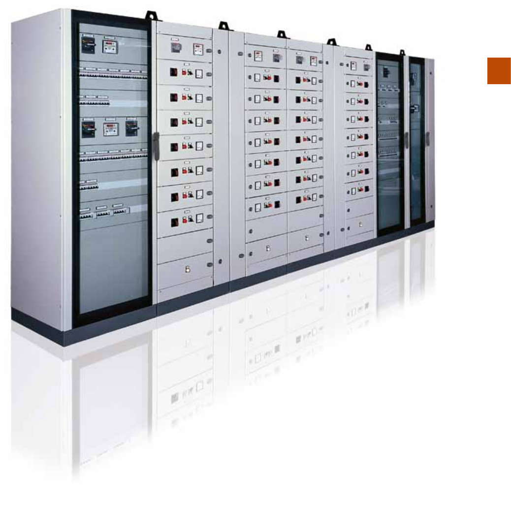
The IS2 panel boards are suitable for making electrical automation, control and
operation panel boards, with the possibility of constructing batteries of cabinets side by
side to control complex industrial plants. They are suitable for floor mounting with the
possibility of lateral and rear access and adjustment of the back plate position.
ABB Technical catalogue | 1STC804013D0205 5/3
5

5/4 1STC804013D0205 | ABB Technical catalogue
5
Main characteristics and applications for IS2 enclosures.
IS2 Enclosures
Main characteristics
Cabinet with blind or glazed door
The skeleton of the panel board consists of galvanised sheet uprights and pickled sheet
panelling with a min. thickness of 15/10. The parts made of pickled sheet are painted with
60÷70 micron thick polyester epoxy powder paint of standard medium orange
peel grey RAL 7035. The painting can be worked (drilled) without chipping. Other colours
are also available on request.
Equipotentiality of the structure is obtained automatically during the assembly stage.
Placing two or more structures side by side is a simple operation, using the least possible
number of accessories. The structure can be fitted with accessories as follows:
- Vertical blind separator between columns, which ensures the degree of protection
- Separator for 24-pole connectors (staggered assembly between the rows) and relative
accessories (closure plates, reduction for the 16-10-6 pole versions).
- Lateral incoming cable structure W=300mm D=500-600-800mm- 1000mm – can be
fitted with the separators described above.
The dimensions referred to conform to DIN 41488, and should be considered as external.
Uprights
The upright section is of the closed type and provides excellent resistance to mechanical
stresses whilst still keeping the max. dimensions of 47x47mm.
They are drilled with 25mm pitch (in conformity with the DIN 43660 Standard) and allow
the accessories to be fixed using M6 self-threading screws and cage nuts. The multi-
purpose hinges for fixing the doors allow several structures to be placed side by side,
and also to make corner batteries.
There is also an intermediate upright, which allows structures with various compartments
to be made (e.g. structure W=800 divided into 600+200mm).
For the structures with width ≥1000mm, the upright can be removed to facilitate access.

ABB Technical catalogue | 1STC804013D0205 5/5
5
Base, top and plinth
The base has openings which allow cable entry from below, and has different types
of flanges:
- guillotine sliding, complete with gasket
- in several pieces of different sizes to be removed or drilled
- completely closed by a single large flange (20/10 thickness), which can be drilled
to house fairlead membranes or for direct entry of large cable bundles.
It can also be fitted with supporting crosspieces for heavy users (e.g.
transformers max. 500Kg)
Various types of plinths are available:
- Standard: 25/10 angle pieces + 10/10 flange made of pickled sheet and painted grey
orange peel RAL 7012 colour, H=100mm.
The flanges are supplied loose. Their assembly is carried out from the front of the panel
board,using two self-threading screws. The angle pieces are fixed to the structure with
two bolts placeddiagonally to prevent any rotations during handling. Handling can be
carried out using transpalletseven when there are two structures side by side.
- Raised H=200mm: this keeps the same characteristics as theprevious one and
consists of two superimposed angle pieces H=100mm and relative cover flange
H=100mm.
- Supporting: able to support the weight of the structure (≈ 300kg loaded) and handle it
by means of rollers. Versions H=100mm.
The plinth can be replaced by the following series of accessories:
- Levelling feet (500kg max. weight)
- Free and braked type wheels (70kg max. weight)
- Single: on request the plinth can be made in a single piece, equal to the whole
perimeter of the panel boards mounted in a battery.
The angle pieces are provided with M12 holes for fixing to the floor.
The roof is of the removable type and can be fitted with air conditioner, ventilation
hoods, top cable connection compartment. The flanges are supplied loose and their
assembly is carried out from the front of the panel board, using two screws.

5/6 1STC804013D0205 | ABB Technical catalogue
5
Door
The reversible type doors (right or left opening) are made of 20/10 thick pickled sheet,
and can be mounted on the four sides with an opening angle of 120° for the front ones,
even in the case of several structures side by side. The side doors have a maximum
opening angle of 100°.
Both handles are fitted with different types of key locks.
Furthermore the doors are fitted with the following series of accessories:
- Hinges with 180° opening
- Door stop in the open position for the 180° version as well
- Release microswitch
- Voltage indication lamp
- Ventilation Kit
- Swivel work surface (only for doors W=600 and 800mm), which can be mounted on
the reinforcement bar
- RAL7035 colour vertical and horizontal A3 format metal document pocket (only for
doors W=600-800-1000mm), which can be mounted on the reinforcement bar
- A4 format plastic document pocket
- Crosspieces on inside of door, for horizontal connection between reinforcement tubes
for fixing the wiring duct or other accessories.
- Aluminium openable windows for control panels fitted with door and key.
- Counterdoor, to be mounted at the same time as the front door.
This can house the main components, such as handles for switch-disconnectors/circuit-
breakers, mushroom-head pushbuttons and various different pushbuttons.
The blind door is fitted with reinforced galvanised tube and drilled with 25mm pitch,
earthing pins (M6) located in the two corners close to the hinges. The transparent door
is fitted with safety glass 4 mm thick screen-printed and with earthed pins.
IS2 Enclosures
Main characteristics
Large functional plate
The structure of the large plate is particularly sturdy it can support loads up to a total of
300kg without undergoing any deformation.
Made of galvanised sheet (25/10 thick), it is mounted on sliding blocks, which facilitate its
insertion in the panel board in any one of the following ways:
- From the front
- From the side
- From the rear
- Two “back-to-back” plates; also in the version with opposite plate
- Fully to the rear, placed inside the uprights on the same plane as these.
The plates, which can be adjusted in depth every 25mm, have the same heights and can
be in oneof the following versions:
- Standard: with insertion from the front or rear. Joining with another plate is carried out
using thespecial kit. Insertion from the side is possible by means of sliding tracks.
- Oversized: in this case the useful width is the same as the width of the structure.
Assembly canonly be from the side and is carried out thanks to the special tracks. The
oversized plate can be adjustedin depth to exploit the useful space to the maximum
without interfering with the side-by-side kit.
It can be joined to other plates with the help of a few accessories which can be
mounted from the front.
- Partial: adjustable in depth, thisis installed using accessories.The back plates can
befitted with rear reinforcement crosspieces.

In the cabinets with glazed doors, the useful space between the glass and panels/
counterdoor allows assembly of most of the components, among which: fixed circuit-
breakers with transmitted rotary operation, OESA-OETL switch-disconnectors, Tmax
circuit-breakers, and various pushbuttons.
Cabinet with 19” rack frame
The following types of frame are available:
- Fixed: adjustable in depth with 25mm pitch, able to support a maximum load of 90Kg.
With 38, 42, 47 HE module capacity for panel boards 1800, 2000, 2200mm high
respectively, width 600, 800mm.
- Swing: in the versions for off-centre mounting in structures with W=800mm and
centred in structures with W =600mm with a capacity of 36, 40, 45 HE modules
respectively for 1800, 2000 and 2200mm heights.
- Partial swing: with 9, 18, 27 HE module capacity, for frames 500, 900, 1300mm high
respectively.
The rack frames are completed with the special blind closure panels with dimensions
from 1 HE to 20 HE.
Cabinet with 19’’ rack frame fixed with cranked shaped profile, swing decentralized
“C” shaped profile and accessories
Other fastening systems for rack 19’’ are available, provided with new accessories on
catalogue:
- Fixed: fastening systems for rack 19’’ with fixed cranked shaped profile uprights at full
height in enclosure W=600mm and W=800mm, capacity 38/42/47 HE
- Partial fixed: fastening systems for rack 19’’ with fixed cranked shaped profile uprights
at partial height in enclosure W=600mm and W=800mm, capacity 9/18/27 HE
- Swing: decentralized rack frame with swing decentralized “C” shaped profile for
W=800mm, capacity 36/41/45 HE.
Brackets for fixing in W=600mm and W=800mm are available, crosspieces have
dedicated slots for the passage of cables and for the ducts fixing. Support for accessories,
universal fixed, adjustable in deep or removable shelves plus DIN-rail codes are included in
ABB offer for those codes.
Cabinet with compartments
The IS2 range also covers construction of versions with cells or compartments.
The compartments, available in heights multiples of 100mm up to amaximum of 800mm,
allow Form 3a type segregation to be obtained.
The galvanised sheet back plate can be removed to facilitate assembly of the apparatus.
The side parts of the compartment are pre-sheared for passage of the conductors.
ABB Technical catalogue | 1STC804013D0205 5/7
5

IS2 Enclosures
Main characteristics
The cabinet is fitted with a glazed door for the video part and can take screens up to
17” in size.
Cabinet for modular configurations
In the 600 and 800mm widths (24 and 36 DIN modules) without cable riser and in the
800/1000/1200mm widths with internal cable riser W=200 or 400mm, the IS2 cabinets
can be fitted with modular panels. The modular panels are available in the version with
DIN drilling (for one or three rows of modular apparatus), in the blind version and for
72x72mm and 96x96mm measuring instruments. All the panels have vertical modularity
of 150 or 200mm and are available in the fixed or hinged version by means of an
accessory. Installation of Tmax moulded-case circuit-breakers is possible by means of a
back plate and blind panels.
Installation of the modular panels in the IS2 cabinets requires the use of the special
uprights for IS2 Enclosures for Automation General characteristics and applications
Cabinet for PC In this configuration, the cabinet is fitted with a glazed door for the
video part and can take screens up to 17” in size. The window only regards the screen
part. The part relative to the CPU is located behind the keyboard surface, accessible
through a lift-up top fitted with a key lock.
The PC cabinet can be placed alongside the basic structures.
Available in 1800/2000/2200mm heights, 600mm width, and 600/800mm depth.
Cabinet with console The structure is fitted with a section dedicated to a console. The
versions available are with blind or glazed door.
modular panels which are screwed onto the structure of the cabinet. Alternatively
assembly of the apparatus on an oversized back plate is possible by means of
dedicated uprights.
The modular versions are also fitted with the following series of accessories:
- Hole cover W=2000mm grey RAL 7035 colour
- Adhesive circuit identification label holders
- Distribution frames
Cabinet for PC
In this configuration, the cabinet is fitted with a glazed door for the video part and can
take screens up to 17” in size. The window only regards the screen part. The part relative
to the CPU is located behind the keyboard surface, accessible through a lift-up top fitted
with a key lock.
The PC cabinet can be placed alongside the basic structures. Available in
1800/2000/2200mm heights, 600mm width, and 600/800mm depth.
Cabinet with console
The structure is fitted with a section dedicated to a console. The versions available are
with blind or glazed door.
5/8 1STC804013D0205 | ABB Technical catalogue
5

In the 600 and 800mm widths (24 and 36 DIN modules) without cable riser and in the
800/1000/1200mm widths with internal cable riser W=200 or 400mm, the IS2 cabinets
can be fitted with modular panels.
Air conditioners/fans
There are several solutions for air conditioning and ventilation cabinets:
- Air conditioners, ultra-thin (max depth 105 mm) for wall mounting, IP54, 230 V, 50/60
Hz, 400 V 50 Hz, 460 V 60 Hz, RAL 7035, with a cooling capacity from 1900 W to
2940 W.
- Air conditioners for wall or door mounting, 230V 50/60Hz, RAL 7035 with cooling
power of 600 W to 2200 W.
- Heat exchangers (air - air) for wall mounting, IP54, 230 V 50/60 Hz, RAL 7035 with
cooling power from 35 W to 85 W.
- Kit natural ventilation through Kit for the raising of the roof IP 20 and grid
- Natural ventilation kit through grid IP21 / IP54
- Forced ventilation kit through input grid and output fan on the wall or hood outlet on the
roof, IP23 / IP54, 7035, 230V / 115V, 50/60Hz with reversible flow, flow rate of 23 m3/h
590 m3/h.
- Heater IP20, with 110/230V power supply 50 / 60 Hz
- Thermostat with 110V, 250V power supply 50 / 60 Hz
Accessories
Apart from the accessories dedicated to making up some versions, the following
are available for the whole range:
- Reinforcement crosspieces for transformers, able to support weights of 500kg.
They are placed at the back of the structure in depth
- Reinforcement crosspieces/various applications, which can be mounted both in depth
and in width (H=48-100mm). They are independent of the dimensions of the structure
and can be positioned both inside and outside the uprights
- Guide a “C” guides in depth for mounting DIN rails and blind back plates
- Blind panels (H=50-100-150-200-400-600mm) and DIN cut-outs (H=150- 200mm)
- Lamps for panel board internal lighting, to be installed directly on the upright
placed under the roof. They can be of two types: 8-13W fluorescent tube with 220-
240V 50/60Hz power supply, or 11W version with integrated UNEL socket
- “Duct” type accessory able to shield the power cables from the signal cables
- Busbar system
Technical characteristics
Conformity with the Standard IEC62208, IEC60439-1, IEC 61439-1-2
Degree of protection IP65 (IEC60529) with fixed flange
TYPE 12 (UL Standard)
Degree of mechanical strength IK10 blind door
IK09 glazed door
(IEC 62262)
Certifications II 3 G D
Type of material Metallic
Installation site Indoors
Fixing method floor
Normal service conditions –
ambient temperature from –5 to +40° C
Operating climate (t°/rh%) costant 23°C/83% - 40°C/93%
variable 23°C/98% - 40°C/98%
Vibration test In accordance with Standard IEC 60068-2-57
Seismic withstand capability test In accordance with Standard IEE Std 693
ABB Technical catalogue | 1STC804013D0205 5/9
5

5/10 1STC804013D0205 | ABB Technical catalogue
5
IS2 Enclosures
Main characteristics
Composition of the series
Dimensions (mm) Back plates
Counterdoor
Top cable
connection cont.
Modular
DIN structure
Cable container
19” rack structures
Structures with
compartments
Cabinet with
console
Cabinet for
computerr IS2 EMC
H D W Standard Oversized Internal W=200mm Internal W=400mm External W=300mm
1800
2000
2200
400
300 •
400 • •
600 ••••• •••
800 • • • • • • • • •
1000 • • • • • + cable cont. • • • + cable cont.
1200 • • • • + cable cont. • • + cable cont.
500
300 •
400 • • •
600 ••••• •••
800 • • • • • • • • •
1000 • • • • • + cable cont. • • • + cable cont.
1200 • • • • + cable cont. • • + cable cont.
1600 • • •
600
300
400 • • •
600 ••••• ••••• (1)
800 • • • • • • • • • • (1)
1000 • • • • • + cable cont. • • • + cable cont.
1200 • • • • + cable cont. • • + cable cont.
1600 • •
800
300 •
400 • • •
600 ••••• ••••• (1)
800 • • • • • • • • • • (1)
1000 • • • • • + cable cont. • • • + cable cont.
1200 • • • • + cable cont. • • + cable cont.
1600 • •
1000
300 •
400 • • •
600 ••••• • •
800 • • • • • • • •
1000 • • • • • • • • + cable cont.
(1) Only H=2000mm

ABB Technical catalogue | 1STC804013D0205 5/11
5
Dimensions (mm) Back plates
Counterdoor
Top cable
connection cont.
Modular
DIN structure
Cable container
19” rack structures
Structures with
compartments
Cabinet with
console
Cabinet for
computerr IS2 EMC
H D W Standard Oversized Internal W=200mm Internal W=400mm External W=300mm
1800
2000
2200
400
300 •
400 • •
600 ••••• •••
800 • • • • • • • • •
1000 • • • • • + cable cont. • • • + cable cont.
1200 • • • • + cable cont. • • + cable cont.
500
300 •
400 • • •
600 ••••• •••
800 • • • • • • • • •
1000 • • • • • + cable cont. • • • + cable cont.
1200 • • • • + cable cont. • • + cable cont.
1600 • • •
600
300
400 • • •
600 ••••• ••••• (1)
800 • • • • • • • • • • (1)
1000 • • • • • + cable cont. • • • + cable cont.
1200 • • • • + cable cont. • • + cable cont.
1600 • •
800
300 •
400 • • •
600 ••••• ••••• (1)
800 • • • • • • • • • • (1)
1000 • • • • • + cable cont. • • • + cable cont.
1200 • • • • + cable cont. • • + cable cont.
1600 • •
1000
300 •
400 • • •
600 ••••• • •
800 • • • • • • • •
1000 • • • • • • • • + cable cont.
(1) Only H=2000mm

W D
H
100
BABAB
200 600
800 400 600
800
5/12 1STC804013D0205 | ABB Technical catalogue
5
Pre-assembled IS2 Cabinets
Selection of the structure - H=1800 mm
Rapid selection table
External
dimensions
H=1800(*)mm
Cabinet
without door
Cabinet with door Cabinet with cable container Cabinet with compartments (7) Flanges for plinth Incoming cable flanges
Side
covers Counterdoor Back plates Rack frames 19” “L” shaped profile(5) Rack frames 19”
External
cable container
Blind door
Double
blind with
overload
closure (1) Glazed door
Blind
door with
cable
container
W=200mm
Blind
door with
cable
container
W=400mm
Glazed
door with
cable
container
W=200mm
Glazed
door with
cable
container
W=400mm
Width Width
Front/
rear Sliding Fixed Modular
No. 2 Blind
panel(10)
Side door
with closing
box Standard(2)
Oversize
+
tracks (3)
Fixed
Centred
Swing
Fixed(8)
cranked shaped
uprights
Swing(9)
“C” shaped
profile
W
(mm)
D
(mm)
A
(mm)
B
(mm)
A
(mm)
B
(mm) Side
Centred
W=600mm
Eccentric
W=800mm
Frame+
Fixing kit
Optional central
fixing kit
Frame+
Fixing kit W=300mm
400
400
ES1844K ZN4000
ZN4000
EF4040 EF4042 EF4041
EL1840K EC1841K
EA1841 EA1940
ER3040K
600 ES1864SPK ES1864K ES1864VK ES1864MFK - 600 ZN6000 EF6040 EF6043 EF6041 EE1860K EA1860 EA1960 EG1800 EG1801K EG1805+
EB6000 EB0400
800 ES1884SPK ES1884K ES1884VK ES1884FV2K ES1884VC2K ES1884MF2K 200 600 ES1884MFK - 800 ZN8000 EF8040 EF8042 EF8041 EE1880K EA1880 EA1981 EG1880 EG1803K EG1805+
EB8000
EB8001 +
EB0400
EG1804K+
EV0007
1000 ES1804K ES1814BK ES1804VK ES1804FV2K ES1804FV4K ES1804VC2K ES1804VC4K ES1804MF4K 400 600 ES1804MF2K 200 800 ZN1000 EF1040 EF1042 EF1041 EE1810K EA1810 EA1910
1200 ES1824BK ES1824VK(**) ES1824FV4K ES1824VC4K ES1824MF4K 400 800 2xZN6000 2xEF6040 2xEF6043 2xEF6041 EA1812 EA1912
400
500
ES1845K ZN4000
ZN5000
EF4050 EF4052 EF4051
EL1850K EC1851K
EA1841 EA1940
ER3050K
600 ES1865SPK ES1865K ES1865VK ES1865MFK - 600 ZN6000 EF6050 EF6052 EF6051 EE1860K EA1860 EA1960 EG1800 EG1801K EG1805+
EB6000 EB0500
800 ES1885K ES1885VK ES1885FV2K ES1885VC2K ES1885MF2K 200 600 ES1885MFK - 800 ZN8000 EF8050 EF8052 EF8051 EE1880K EA1880 EA1981 EG1880 EG1803K EG1805+
EB8000
EB8001 +
EB0500
EG1804K+
EV0007
1000 ES1805K ES1815BK ES1805VK ES1805FV2K ES1805FV4K ES1805VC2K ES1805VC4K ES1805MF4K 400 600 ES1805MF2K 200 800 ZN1000 EF1053 EF1052 EF1051 EE1810K EA1810 EA1910
1200 ES1827BK ES1825VK(**) ES1825FV4K ES1825VC4K ES1825MF4K 400 800 2xZN6000 2xEF6050 2xEF6052 2xEF6051 EA1812 EA1912
1600(6) ES1875BK 2xZN8000 2xEF8050 2xEF8052 2xEF8051 EA1817 EA1916(4)
400
600
ES1846K ZN4000
ZN6000
EF4060 EF4063 EF4061
EL1860K EC1861K
EA1841 EA1940
ER3060K
600 ES1866SPK ES1866K ES1866VK ES1866MFK - 600 ZN6000 EF6060 EF6062 EF6061 EE1860K EA1860 EA1960 EG1800 EG1801K EG1805+
EB6000 EB0600
800 ES1886SPK ES1886K ES1886VK ES1886FV2K ES1886VC2K ES1886MF2K 200 600 ES1886MFK - 800 ZN8000 EF8060 EF8062 EF8061 EE1880K EA1880 EA1981 EG1880 EG1803K EG1805+
EB8000
EB8001 +
EB0600
EG1804K+
EV0007
1000 ES1806K ES1816BK ES1806VK ES1806FV2K ES1806FV4K ES1806VC2K ES1806VC4K ES1806MF4K 400 600 ES1806MF2K 200 800 ZN1000 EF1060 EF1062 EF1061 EE1810K EA1810 EA1910
1200 ES1826BK ES1826VK(**) ES1826FV4K ES1826VC4K ES1826MF4K 400 800 2xZN6000 2xEF6060 2xEF6062 2xEF6061 EA1812 EA1912
1600(6) ES1876BK 2xZN8000 2xEF8060 2xEF8062 2xEF8061 EA1817 EA1916(4)
400
800
ES1848K ZN4000
ZN8000
EF4080 EF4082 EF4081
EL1880K EC1881K
EA1841 EA1940
ER3080K
600 ES1868K ES1868VK ES1868MFK - 600 ZN6000 EF6080 EF6082 EF6081 EE1860K EA1860 EA1960 EG1800 EG1801K EG1805+
EB6000 EB0800
800 ES1888K ES1888VK ES1888FV2K ES1888VC2K ES1888MF2K 200 600 ES1888MFK - 800 ZN8000 EF8080 EF8082 EF8081 EE1880K EA1880 EA1981 EG1880 EG1803K EG1805+
EB8000
EB8001 +
EB0800
EG1804K+
EV0007
1000 ES1808K ES1818BK ES1808VK ES1808FV2K ES1808FV4K ES1808VC2K ES1808VC4K ES1808MF4K 400 600 ES1808MF2K 200 800 ZN1000 EF1080 EF1082 EF1081 EE1810K EA1810 EA1910
1200 ES1828BK ES1828VK(**) ES1828FV4K ES1828VC4K ES1828MF4K 400 800 2xZN6000 2xEF6080 2xEF6082 2xEF6081 EA1812 EA1912
1600(6) ES1878BK 2xZN8000 2xEF8080 2xEF8082 2xEF8081 EA1817 EA1916(4)
400
1000
ES1840K ZN4000
ZN1000
EF4010 EF4012 EF4011
EL1810K EC1811K
EA1841 EA1940
ER3010K
600 ES1860K ES1860VK ES1860MFK - 600 ZN6000 EF6010 EF6012 EF6011 EE1860K EA1860 EA1960 EG1800 EG1801K EG1805+
EB6000 EB1000
800 ES1880K ES1880VK ES1880MF2K 200 600 ES1880MFK - 800 ZN8000 EF8010 EF8012 EF8011 EA1880 EA1981 EG1880 EG1803K EG1805+
EB8000
EB8001 +
EB1000
EG1804K+
EV0007
1000 ES1800K ES1810BK ES1800VK ES1800MF4K 400 600 ES1800MF2K 200 800 ZN1000 EF1010 EF1012 EF1011 EE1810K EA1810 EA1910
(*) The useful height is always 100mm less than the external dimension of the panel board. For the version with compartments, the useful height is 200mm less.
(**) Implies mounting the intermediate upright EM1801. The doors have overlapping closure on the intermediate upright (removable) fixed onto the crosspieces mounted in depth.
(1) Also available with double blind doors with closing on intermediate upright (eliminate the suffix B from the code).
(2) Standard plate joining kit: EA1800 (H=1800mm); EA2000 (H=2000mm); EA2200 (H=2200mm). Possibility of lateral insertion with tracks (see pag. 5/57).
(3) EA2113 oversized plate joining kit H=1800/2000/2200mm.
(4) Kit consisting of 2 oversized back plates with relative insertion tracks + plate joining kit.
(5)
In case of structures with internal cable container, select the correct rack frame which takes into account the W=200 or W=400mm of the cable container; and leaves W=600mm or W=800mm structure compartment.
(6) W=1600mm enclosures are only available in pre-assembled version with blind door (with overlapping door or intermediate upright).
(7) Examples of configuration and technical characteristics at page 5/114 and 5/115

W D
H
100
BABAB
200 600
800 400 600
800
ABB Technical catalogue | 1STC804013D0205 5/13
5
> Ordering codes page 5/26 > Examples of configuration page 5/112 > In-depth technical information page 8/1 > Overall dimensions page 9/1
External
dimensions
H=1800(*)mm
Cabinet
without door
Cabinet with door Cabinet with cable container Cabinet with compartments (7) Flanges for plinth Incoming cable flanges
Side
covers Counterdoor Back plates Rack frames 19” “L” shaped profile(5) Rack frames 19”
External
cable container
Blind door
Double
blind with
overload
closure (1) Glazed door
Blind
door with
cable
container
W=200mm
Blind
door with
cable
container
W=400mm
Glazed
door with
cable
container
W=200mm
Glazed
door with
cable
container
W=400mm
Width Width
Front/
rear Sliding Fixed Modular
No. 2 Blind
panel(10)
Side door
with closing
box Standard(2)
Oversize
+
tracks (3)
Fixed
Centred
Swing
Fixed(8)
cranked shaped
uprights
Swing(9)
“C” shaped
profile
W
(mm)
D
(mm)
A
(mm)
B
(mm)
A
(mm)
B
(mm) Side
Centred
W=600mm
Eccentric
W=800mm
Frame+
Fixing kit
Optional central
fixing kit
Frame+
Fixing kit W=300mm
400
400
ES1844K ZN4000
ZN4000
EF4040 EF4042 EF4041
EL1840K EC1841K
EA1841 EA1940
ER3040K
600 ES1864SPK ES1864K ES1864VK ES1864MFK - 600 ZN6000 EF6040 EF6043 EF6041 EE1860K EA1860 EA1960 EG1800 EG1801K EG1805+
EB6000 EB0400
800 ES1884SPK ES1884K ES1884VK ES1884FV2K ES1884VC2K ES1884MF2K 200 600 ES1884MFK - 800 ZN8000 EF8040 EF8042 EF8041 EE1880K EA1880 EA1981 EG1880 EG1803K EG1805+
EB8000
EB8001 +
EB0400
EG1804K+
EV0007
1000 ES1804K ES1814BK ES1804VK ES1804FV2K ES1804FV4K ES1804VC2K ES1804VC4K ES1804MF4K 400 600 ES1804MF2K 200 800 ZN1000 EF1040 EF1042 EF1041 EE1810K EA1810 EA1910
1200 ES1824BK ES1824VK(**) ES1824FV4K ES1824VC4K ES1824MF4K 400 800 2xZN6000 2xEF6040 2xEF6043 2xEF6041 EA1812 EA1912
400
500
ES1845K ZN4000
ZN5000
EF4050 EF4052 EF4051
EL1850K EC1851K
EA1841 EA1940
ER3050K
600 ES1865SPK ES1865K ES1865VK ES1865MFK - 600 ZN6000 EF6050 EF6052 EF6051 EE1860K EA1860 EA1960 EG1800 EG1801K EG1805+
EB6000 EB0500
800 ES1885K ES1885VK ES1885FV2K ES1885VC2K ES1885MF2K 200 600 ES1885MFK - 800 ZN8000 EF8050 EF8052 EF8051 EE1880K EA1880 EA1981 EG1880 EG1803K EG1805+
EB8000
EB8001 +
EB0500
EG1804K+
EV0007
1000 ES1805K ES1815BK ES1805VK ES1805FV2K ES1805FV4K ES1805VC2K ES1805VC4K ES1805MF4K 400 600 ES1805MF2K 200 800 ZN1000 EF1053 EF1052 EF1051 EE1810K EA1810 EA1910
1200 ES1827BK ES1825VK(**) ES1825FV4K ES1825VC4K ES1825MF4K 400 800 2xZN6000 2xEF6050 2xEF6052 2xEF6051 EA1812 EA1912
1600(6) ES1875BK 2xZN8000 2xEF8050 2xEF8052 2xEF8051 EA1817 EA1916(4)
400
600
ES1846K ZN4000
ZN6000
EF4060 EF4063 EF4061
EL1860K EC1861K
EA1841 EA1940
ER3060K
600 ES1866SPK ES1866K ES1866VK ES1866MFK - 600 ZN6000 EF6060 EF6062 EF6061 EE1860K EA1860 EA1960 EG1800 EG1801K EG1805+
EB6000 EB0600
800 ES1886SPK ES1886K ES1886VK ES1886FV2K ES1886VC2K ES1886MF2K 200 600 ES1886MFK - 800 ZN8000 EF8060 EF8062 EF8061 EE1880K EA1880 EA1981 EG1880 EG1803K EG1805+
EB8000
EB8001 +
EB0600
EG1804K+
EV0007
1000 ES1806K ES1816BK ES1806VK ES1806FV2K ES1806FV4K ES1806VC2K ES1806VC4K ES1806MF4K 400 600 ES1806MF2K 200 800 ZN1000 EF1060 EF1062 EF1061 EE1810K EA1810 EA1910
1200 ES1826BK ES1826VK(**) ES1826FV4K ES1826VC4K ES1826MF4K 400 800 2xZN6000 2xEF6060 2xEF6062 2xEF6061 EA1812 EA1912
1600(6) ES1876BK 2xZN8000 2xEF8060 2xEF8062 2xEF8061 EA1817 EA1916(4)
400
800
ES1848K ZN4000
ZN8000
EF4080 EF4082 EF4081
EL1880K EC1881K
EA1841 EA1940
ER3080K
600 ES1868K ES1868VK ES1868MFK - 600 ZN6000 EF6080 EF6082 EF6081 EE1860K EA1860 EA1960 EG1800 EG1801K EG1805+
EB6000 EB0800
800 ES1888K ES1888VK ES1888FV2K ES1888VC2K ES1888MF2K 200 600 ES1888MFK - 800 ZN8000 EF8080 EF8082 EF8081 EE1880K EA1880 EA1981 EG1880 EG1803K EG1805+
EB8000
EB8001 +
EB0800
EG1804K+
EV0007
1000 ES1808K ES1818BK ES1808VK ES1808FV2K ES1808FV4K ES1808VC2K ES1808VC4K ES1808MF4K 400 600 ES1808MF2K 200 800 ZN1000 EF1080 EF1082 EF1081 EE1810K EA1810 EA1910
1200 ES1828BK ES1828VK(**) ES1828FV4K ES1828VC4K ES1828MF4K 400 800 2xZN6000 2xEF6080 2xEF6082 2xEF6081 EA1812 EA1912
1600(6) ES1878BK 2xZN8000 2xEF8080 2xEF8082 2xEF8081 EA1817 EA1916(4)
400
1000
ES1840K ZN4000
ZN1000
EF4010 EF4012 EF4011
EL1810K EC1811K
EA1841 EA1940
ER3010K
600 ES1860K ES1860VK ES1860MFK - 600 ZN6000 EF6010 EF6012 EF6011 EE1860K EA1860 EA1960 EG1800 EG1801K EG1805+
EB6000 EB1000
800 ES1880K ES1880VK ES1880MF2K 200 600 ES1880MFK - 800 ZN8000 EF8010 EF8012 EF8011 EA1880 EA1981 EG1880 EG1803K EG1805+
EB8000
EB8001 +
EB1000
EG1804K+
EV0007
1000 ES1800K ES1810BK ES1800VK ES1800MF4K 400 600 ES1800MF2K 200 800 ZN1000 EF1010 EF1012 EF1011 EE1810K EA1810 EA1910
(8) Rack frame W=600mm needs fixing brackets EB6000 and for an optional central fixing order a couple of crosspieces EB... see page 5/63 according to switchboard depth. Accessories from page 5/84.
Rack frame W=800mm needs fixing brackets EB8000 and for an optional central fixing order a couple of crosspieces EB... see page 5/63 according to switchboard depth. Moreover, fixing kits replacing
brackets and crosspieces according to switchboard depth are available, codes on page 5/80. Accessories from page 5/84.
(9) Only available for W=800mm (even in structures with cable container and W=800mm structure compartment). Order specific fixing kit EV0007.
(10) Single side panel available on page 5/49.
Kit for placing structures side by side EV0002/EV0003/EV0006 see page 5/70.

W D
H
100
BABAB
200 600
800 400 600
800
5/14 1STC804013D0205 | ABB Technical catalogue
5
Pre-assembled IS2 Cabinets
Selection of the structure - H=2000 mm
Rapid selection table
External
dimensions
H=2000(*)mm
Cabinet
without door
Cabinet with door Cabinet with cable container Cabinet with compartments (7) Flanges for plinth Incoming cable flanges
Side
covers Counterdoor Back plates Rack frames 19” “L” shaped profile(5) Rack frames 19”
External
cable container
Blind door
Double
blind with
overload
closure (1) Glazed door
Blind
door with
cable
container
W=200mm
Blind
door with
cable
container
W=400mm
Glazed
door with
cable
container
W=200mm
Glazed
door with
cable
container
W=400mm
Width Width
Front/
rear Sliding Fixed Modular
No. 2 Blind
panel(10)
Side door
with closing
box Standard(2)
Oversize
+
tracks (3)
Fixed
Centred
Swing
Fixed(8)
cranked shaped
uprights
Swing(9)
“C” shaped
profile
W
(mm)
D
(mm)
A
(mm)
B
(mm)
A
(mm)
B
(mm) Side
Centred
W=600mm
Eccentric
W=800mm
Frame+
Fixing kit
Optional central
fixing kit
Frame+
Fixing kit W=300mm
400
400
ES2044K ZN4000
ZN4000
EF4040 EF4042 EF4041
EL2040K EC2041K
EA2040 EA2140
ER3041K
600 ES2064SPK ES2064K ES2064VK ES2064MFK - 600 ZN6000 EF6040 EF6043 EF6041 EE2060K EA2060 EA2160 EG2000 EG2001K EG2005+
EB6000 EB0400
800 ES2084SPK ES2084K ES2084VK ES2084FV2K ES2084VC2K ES2084MF2K 200 600 ES2084MFK - 800 ZN8000 EF8040 EF8042 EF8041 EE2080K EA2080 EA2181 EG2080 EG2003K EG2005+
EB8000
EB8001 +
EB0400
EG2004K+
EV0007
1000 ES2004K ES2014BK ES2004VK ES2004FV2K ES2004FV4K ES2004VC2K ES2004VC4K ES2004MF4K 400 600 ES2004MF2K 200 800 ZN1000 EF1040 EF1042 EF1041 EE2010K EA2010 EA2110
1200 ES2024BK ES2024VK(**) ES2024FV4K ES2024VC4K ES2024MF4K 400 800 2xZN6000 2xEF6040 2xEF6043 2xEF6041 EA2012 EA2112
400
500
ES2045K ZN4000
ZN5000
EF4050 EF4052 EF4051
EL2050K EC2051K
EA2040 EA2140
ER3051K
600 ES2065SPK ES2065K ES2065VK ES2065MFK - 600 ZN6000 EF6050 EF6052 EF6051 EE2060K EA2060 EA2160 EG2000 EG2001K EG2005+
EB6000 EB0500
800 ES2085K ES2085VK ES2085FV2K ES2085VC2K ES2085MF2K 200 600 ES2085MFK - 800 ZN8000 EF8050 EF8052 EF8051 EE2080K EA2080 EA2181 EG2080 EG2003K EG2005+
EB8000
EB8001 +
EB0500
EG2004K+
EV0007
1000 ES2005K ES2015BK ES2005VK ES2005FV2K ES2005FV4K ES2005VC2K ES2005VC4K ES2005MF4K 400 600 ES2005MF2K 200 800 ZN1000 EF1053 EF1052 EF1051 EE2010K EA2010 EA2110
1200 ES2027BK ES2025VK(**) ES2025FV4K ES2025VC4K ES2025MF4K 400 800 2xZN6000 2xEF6050 2xEF6052 2xEF6051 EA2012 EA2112
1600(6) ES2075BK 2xZN8000 2xEF8050 2xEF8052 2xEF8051 EA2017 EA2116(4)
400
600
ES2046K ZN4000
ZN6000
EF4060 EF4063 EF4061
EL2060K EC2061K
EA2040 EA2140
ER3061K
600 ES2066SPK ES2066K ES2066VK ES2066MFK - 600 ZN6000 EF6060 EF6062 EF6061 EE2060K EA2060 EA2160 EG2000 EG2001K EG2005+
EB6000 EB0600
800 ES2086SPK ES2086K ES2086VK ES2086FV2K ES2086VC2K ES2086MF2K 200 600 ES2086MFK - 800 ZN8000 EF8060 EF8062 EF8061 EE2080K EA2080 EA2181 EG2080 EG2003K EG2005+
EB8000
EB8001 +
EB0600
EG2004K+
EV0007
1000 ES2006K ES2016BK ES2006VK ES2006FV2K ES2006FV4K ES2006VC2K ES2006VC4K ES2006MF4K 400 600 ES2006MF2K 200 800 ZN1000 EF1060 EF1062 EF1061 EE2010K EA2010 EA2110
1200 ES2026BK ES2026VK(**) ES2026FV4K ES2026VC4K ES2026MF4K 400 800 2xZN6000 2xEF6060 2xEF6062 2xEF6061 EA2012 EA2112
1600(6) ES2076BK 2xZN8000 2xEF8060 2xEF8062 2xEF8061 EA2017 EA2116(4)
400
800
ES2048K ZN4000
ZN8000
EF4080 EF4082 EF4081
EL2080K EC2081K
EA2040 EA2140
ER3081K
600 ES2068K ES2068VK ES2068MFK - 600 ZN6000 EF6080 EF6082 EF6081 EE2060K EA2060 EA2160 EG2000 EG2001K EG2005+
EB6000 EB0800
800 ES2088K ES2088VK ES2088FV2K ES2088VC2K ES2088MF2K 200 600 ES2088MFK - 800 ZN8000 EF8080 EF8082 EF8081 EE2080K EA2080 EA2181 EG2080 EG2003K EG2005+
EB8000
EB8001 +
EB0800
EG2004K+
EV0007
1000 ES2008K ES2020BK ES2008VK ES2008FV2K ES2008FV4K ES2008VC2K ES2008VC4K ES2008MF4K 400 600 ES2008MF2K 200 800 ZN1000 EF1080 EF1082 EF1081 EE2010K EA2010 EA2110
1200 ES2028BK ES2028VK(**) ES2028FV4K ES2028VC4K ES2028MF4K 400 800 2xZN6000 2xEF6080 2xEF6082 2xEF6081 EA2012 EA2112
1600(6) ES2078BK 2xZN8000 2xEF8080 2xEF8082 2xEF8081 EA2017 EA2116(4)
400
1000
ES2040K ZN4000
ZN1000
EF4010 EF4012 EF4011
EL2010K EC2011K
EA2040 EA2140
ER3011K
600 ES2060K ES2060VK ES2060MFK - 600 ZN6000 EF6010 EF6012 EF6011 EE2060K EA2060 EA2160 EG2000 EG2001K EG2005+
EB6000 EB1000
800 ES2080K ES2080VK ES2080MF2K 200 600 ES2080MFK - 800 ZN8000 EF8010 EF8012 EF8011 EA2080 EA2181 EG2080 EG2003K EG2005+
EB8000
EB8001 +
EB1000
EG2004K+
EV0007
1000 ES2000K ES2010BK ES2000VK ES2000MF4K 400 600 ES2000MF2K 200 800 ZN1000 EF1010 EF1012 EF1011 EE2010K EA2010 EA2110
(*) The useful height is always 100mm less than the external dimension of the panel board. For the version with compartments, the useful height is 200mm less.
(**) Implies mounting the intermediate upright EM1801. The doors have overlapping closure on the intermediate upright (removable) fixed onto the crosspieces mounted in depth.
(1) Also available with double blind doors with closing on intermediate upright (eliminate the suffix B from the code).
(2) Standard plate joining kit: EA1800 (H=1800mm); EA2000 (H=2000mm); EA2200 (H=2200mm). Possibility of lateral insertion with tracks (see pag. 5/57).
(3) EA2113 oversized plate joining kit H=1800/2000/2200mm.
(4) Kit consisting of 2 oversized back plates with relative insertion tracks + plate joining kit.
(5)
In case of structures with internal cable container, select the correct rack frame which takes into account the W=200 or W=400mm of the cable container; and leaves W=600mm or W=800mm structure compartment.
(6) W=1600mm enclosures are only available in pre-assembled version with blind door (with overlapping door or intermediate upright).
(7) Examples of configuration and technical characteristics at page 5/114 and 5/115

W D
H
100
BABAB
200 600
800 400 600
800
ABB Technical catalogue | 1STC804013D0205 5/15
5
> Ordering codes page 5/26 > Examples of configuration page 5/112 > In-depth technical information page. 8/1 > Overall dimensions page 9/1
External
dimensions
H=2000(*)mm
Cabinet
without door
Cabinet with door Cabinet with cable container Cabinet with compartments (7) Flanges for plinth Incoming cable flanges
Side
covers Counterdoor Back plates Rack frames 19” “L” shaped profile(5) Rack frames 19”
External
cable container
Blind door
Double
blind with
overload
closure (1) Glazed door
Blind
door with
cable
container
W=200mm
Blind
door with
cable
container
W=400mm
Glazed
door with
cable
container
W=200mm
Glazed
door with
cable
container
W=400mm
Width Width
Front/
rear Sliding Fixed Modular
No. 2 Blind
panel(10)
Side door
with closing
box Standard(2)
Oversize
+
tracks (3)
Fixed
Centred
Swing
Fixed(8)
cranked shaped
uprights
Swing(9)
“C” shaped
profile
W
(mm)
D
(mm)
A
(mm)
B
(mm)
A
(mm)
B
(mm) Side
Centred
W=600mm
Eccentric
W=800mm
Frame+
Fixing kit
Optional central
fixing kit
Frame+
Fixing kit W=300mm
400
400
ES2044K ZN4000
ZN4000
EF4040 EF4042 EF4041
EL2040K EC2041K
EA2040 EA2140
ER3041K
600 ES2064SPK ES2064K ES2064VK ES2064MFK - 600 ZN6000 EF6040 EF6043 EF6041 EE2060K EA2060 EA2160 EG2000 EG2001K EG2005+
EB6000 EB0400
800 ES2084SPK ES2084K ES2084VK ES2084FV2K ES2084VC2K ES2084MF2K 200 600 ES2084MFK - 800 ZN8000 EF8040 EF8042 EF8041 EE2080K EA2080 EA2181 EG2080 EG2003K EG2005+
EB8000
EB8001 +
EB0400
EG2004K+
EV0007
1000 ES2004K ES2014BK ES2004VK ES2004FV2K ES2004FV4K ES2004VC2K ES2004VC4K ES2004MF4K 400 600 ES2004MF2K 200 800 ZN1000 EF1040 EF1042 EF1041 EE2010K EA2010 EA2110
1200 ES2024BK ES2024VK(**) ES2024FV4K ES2024VC4K ES2024MF4K 400 800 2xZN6000 2xEF6040 2xEF6043 2xEF6041 EA2012 EA2112
400
500
ES2045K ZN4000
ZN5000
EF4050 EF4052 EF4051
EL2050K EC2051K
EA2040 EA2140
ER3051K
600 ES2065SPK ES2065K ES2065VK ES2065MFK - 600 ZN6000 EF6050 EF6052 EF6051 EE2060K EA2060 EA2160 EG2000 EG2001K EG2005+
EB6000 EB0500
800 ES2085K ES2085VK ES2085FV2K ES2085VC2K ES2085MF2K 200 600 ES2085MFK - 800 ZN8000 EF8050 EF8052 EF8051 EE2080K EA2080 EA2181 EG2080 EG2003K EG2005+
EB8000
EB8001 +
EB0500
EG2004K+
EV0007
1000 ES2005K ES2015BK ES2005VK ES2005FV2K ES2005FV4K ES2005VC2K ES2005VC4K ES2005MF4K 400 600 ES2005MF2K 200 800 ZN1000 EF1053 EF1052 EF1051 EE2010K EA2010 EA2110
1200 ES2027BK ES2025VK(**) ES2025FV4K ES2025VC4K ES2025MF4K 400 800 2xZN6000 2xEF6050 2xEF6052 2xEF6051 EA2012 EA2112
1600(6) ES2075BK 2xZN8000 2xEF8050 2xEF8052 2xEF8051 EA2017 EA2116(4)
400
600
ES2046K ZN4000
ZN6000
EF4060 EF4063 EF4061
EL2060K EC2061K
EA2040 EA2140
ER3061K
600 ES2066SPK ES2066K ES2066VK ES2066MFK - 600 ZN6000 EF6060 EF6062 EF6061 EE2060K EA2060 EA2160 EG2000 EG2001K EG2005+
EB6000 EB0600
800 ES2086SPK ES2086K ES2086VK ES2086FV2K ES2086VC2K ES2086MF2K 200 600 ES2086MFK - 800 ZN8000 EF8060 EF8062 EF8061 EE2080K EA2080 EA2181 EG2080 EG2003K EG2005+
EB8000
EB8001 +
EB0600
EG2004K+
EV0007
1000 ES2006K ES2016BK ES2006VK ES2006FV2K ES2006FV4K ES2006VC2K ES2006VC4K ES2006MF4K 400 600 ES2006MF2K 200 800 ZN1000 EF1060 EF1062 EF1061 EE2010K EA2010 EA2110
1200 ES2026BK ES2026VK(**) ES2026FV4K ES2026VC4K ES2026MF4K 400 800 2xZN6000 2xEF6060 2xEF6062 2xEF6061 EA2012 EA2112
1600(6) ES2076BK 2xZN8000 2xEF8060 2xEF8062 2xEF8061 EA2017 EA2116(4)
400
800
ES2048K ZN4000
ZN8000
EF4080 EF4082 EF4081
EL2080K EC2081K
EA2040 EA2140
ER3081K
600 ES2068K ES2068VK ES2068MFK - 600 ZN6000 EF6080 EF6082 EF6081 EE2060K EA2060 EA2160 EG2000 EG2001K EG2005+
EB6000 EB0800
800 ES2088K ES2088VK ES2088FV2K ES2088VC2K ES2088MF2K 200 600 ES2088MFK - 800 ZN8000 EF8080 EF8082 EF8081 EE2080K EA2080 EA2181 EG2080 EG2003K EG2005+
EB8000
EB8001 +
EB0800
EG2004K+
EV0007
1000 ES2008K ES2020BK ES2008VK ES2008FV2K ES2008FV4K ES2008VC2K ES2008VC4K ES2008MF4K 400 600 ES2008MF2K 200 800 ZN1000 EF1080 EF1082 EF1081 EE2010K EA2010 EA2110
1200 ES2028BK ES2028VK(**) ES2028FV4K ES2028VC4K ES2028MF4K 400 800 2xZN6000 2xEF6080 2xEF6082 2xEF6081 EA2012 EA2112
1600(6) ES2078BK 2xZN8000 2xEF8080 2xEF8082 2xEF8081 EA2017 EA2116(4)
400
1000
ES2040K ZN4000
ZN1000
EF4010 EF4012 EF4011
EL2010K EC2011K
EA2040 EA2140
ER3011K
600 ES2060K ES2060VK ES2060MFK - 600 ZN6000 EF6010 EF6012 EF6011 EE2060K EA2060 EA2160 EG2000 EG2001K EG2005+
EB6000 EB1000
800 ES2080K ES2080VK ES2080MF2K 200 600 ES2080MFK - 800 ZN8000 EF8010 EF8012 EF8011 EA2080 EA2181 EG2080 EG2003K EG2005+
EB8000
EB8001 +
EB1000
EG2004K+
EV0007
1000 ES2000K ES2010BK ES2000VK ES2000MF4K 400 600 ES2000MF2K 200 800 ZN1000 EF1010 EF1012 EF1011 EE2010K EA2010 EA2110
(8) Rack frame W=600mm needs fixing brackets EB6000 and for an optional central fixing order a couple of crosspieces EB... see page 5/63 according to switchboard depth. Accessories from page 5/84.
Rack frame W=800mm needs fixing brackets EB8000 and for an optional central fixing order a couple of crosspieces EB... see page 5/63 according to switchboard depth. Moreover, fixing kits replacing
brackets and crosspieces according to switchboard depth are available, codes on page 5/80. Accessories from page 5/84.
(9) Only available for W=800mm (even in structures with cable container and W=800mm structure compartment). Order specific fixing kit EV0007.
(10) Single side panel available on page 5/49.
Kit for placing structures side by side EV0002/EV0003/EV0006 see page 5/70.

W D
H
100
BABAB
200 600
800 400 600
800
5/16 1STC804013D0205 | ABB Technical catalogue
5
Pre-assembled IS2 Cabinets
Selection of the structure - H=2200 mm
Rapid selection table
External
dimensions
H=2200(*)mm
Cabinet
without door
Cabinet with door Cabinet with cable container Cabinet with compartments (7) Flanges for plinth Incoming cable flanges
Side
covers Counterdoor Back plates Rack frames 19” “L” shaped profile(5) Rack frames 19”
External
cable container
Blind door
Double
blind with
overload
closure (1) Glazed door
Blind
door with
cable
container
W=200mm
Blind
door with
cable
container
W=400mm
Glazed
door with
cable
container
W=200mm
Glazed
door with
cable
container
W=400mm
Width Width
Front/
rear Sliding Fixed Modular
No. 2 Blind
panel(10)
Side door
with closing
box Standard(2)
Oversize
+
tracks (3)
Fixed
Centred
Swing
Fixed(8)
cranked shape
uprights
Swing(9)
“C” shaped
profile
W
(mm)
D
(mm)
A
(mm)
B
(mm)
A
(mm)
B
(mm) Side
Centred
W=600mm
Eccentric
W=800mm
Frame+
Fixing kit
Optional central
fixing kit
Frame+
Fixing kit W=300mm
400
400
ES2244K ZN4000
ZN4000
EF4040 EF4042 EF4041
EL2240K EC2241K
EA2240 EA2340
ER3042K
600 ES2264SPK ES2264K ES2264VK ES2264MFK - 600 ZN6000 EF6040 EF6043 EF6041 EE2260K EA2260 EA2360 EG2200 EG2201K EG2205+
EB6000 EB0400
800 ES2284SPK ES2284K ES2284VK ES2284FV2K ES2284VC2K ES2284MF2K 200 600 ES2284MFK - 800 ZN8000 EF8040 EF8042 EF8041 EE2280K EA2280 EA2381 EG2280 EG2203K EG2205+
EB8000
EB8001 +
EB0400
EG2204K+
EV0007
1000 ES2204K ES2214BK ES2204VK ES2204FV2K ES2204FV4K ES2204VC2K ES2204VC4K ES2204MF4K 400 600 ES2204MF2K 200 800 ZN1000 EF1040 EF1042 EF1041 EE2210K EA2210 EA2310
1200 ES2224BK ES2224VK(**) ES2224FV4K ES2224VC4K ES2224MF4K 400 800 2xZN6000 2xEF6040 2xEF6043 2xEF6041 EA2212 EA2312
400
500
ES2245K ZN4000
ZN5000
EF4050 EF4052 EF4051
EL2250K EC2251K
EA2240 EA2340
ER3052K
600 ES2265SPK ES2265K ES2265VK ES2265MFK - 600 ZN6000 EF6050 EF6052 EF6051 EE2260K EA2260 EA2360 EG2200 EG2201K EG2205+
EB6000 EB0500
800 ES2285K ES2285VK ES2285FV2K ES2285VC2K ES2285MF2K 200 600 ES2285MFK - 800 ZN8000 EF8050 EF8052 EF8051 EE2280K EA2280 EA2381 EG2280 EG2203K EG2205+
EB8000
EB8001 +
EB0500
EG2204K+
EV0007
1000 ES2205K ES2215BK ES2205VK ES2205FV2K ES2205FV4K ES2205VC2K ES2205VC4K ES2205MF4K 400 600 ES2205MF2K 200 800 ZN1000 EF1053 EF1052 EF1051 EE2210K EA2210 EA2310
1200 ES2227BK ES2225VK(**) ES2225FV4K ES2225VC4K ES2225MF4K 400 800 2xZN6000 2xEF6050 2xEF6052 2xEF6051 EA2212 EA2312
1600(6) ES2275BK 2xZN8000 2xEF8050 2xEF8052 2xEF8051 EA2217 EA2316(4)
400
600
ES2246K ZN4000
ZN6000
EF4060 EF4063 EF4061
EL2260K EC2261K
EA2240 EA2340
ER3062K
600 ES2266SPK ES2266K ES2266VK ES2266MFK - 600 ZN6000 EF6060 EF6062 EF6061 EE2260K EA2260 EA2360 EG2200 EG2201K EG2205+
EB6000 EB0600
800 ES2286SPK ES2286K ES2286VK ES2286FV2K ES2286VC2K ES2286MF2K 200 600 ES2286MFK - 800 ZN8000 EF8060 EF8062 EF8061 EE2280K EA2280 EA2381 EG2280 EG2203K EG2205+
EB8000
EB8001 +
EB0600
EG2204K+
EV0007
1000 ES2206K ES2216BK ES2206VK ES2206FV2K ES2206FV4K ES2206VC2K ES2206VC4K ES2206MF4K 400 600 ES2206MF2K 200 800 ZN1000 EF1060 EF1062 EF1061 EE2210K EA2210 EA2310
1200 ES2226BK ES2226VK(**) ES2226FV4K ES2226VC4K ES2226MF4K 400 800 2xZN6000 2xEF6060 2xEF6062 2xEF6061 EA2212 EA2312
1600(6) ES2276BK 2xZN8000 2xEF8060 2xEF8062 2xEF8061 EA2217 EA2316(4)
400
800
ES2248K ZN4000
ZN8000
EF4080 EF4082 EF4081
EL2280K EC2281K
EA2240 EA2340
ER3082K
600 ES2268K ES2268VK ES2268MFK - 600 ZN6000 EF6080 EF6082 EF6081 EE2260K EA2260 EA2360 EG2200 EG2201K EG2205+
EB6000 EB0800
800 ES2288K ES2288VK ES2288FV2K ES2288VC2K ES2288MF2K 200 600 ES2288MFK - 800 ZN8000 EF8080 EF8082 EF8081 EE2280K EA2280 EA2381 EG2280 EG2203K EG2205+
EB8000
EB8001 +
EB0800
EG2204K+
EV0007
1000 ES2208K ES2222BK ES2208VK ES2208FV2K ES2208FV4K ES2208VC2K ES2208VC4K ES2208MF4K 400 600 ES2208MF2K 200 800 ZN1000 EF1080 EF1082 EF1081 EE2210K EA2210 EA2310
1200 ES2228BK ES2228VK(**) ES2228FV4K ES2228VC4K ES2228MF4K 400 800 2xZN6000 2xEF6080 2xEF6082 2xEF6081 EA2212 EA2312
1600(6) ES2278BK 2xZN8000 2xEF8080 2xEF8082 2xEF8081 EA2217 EA2316(4)
400
1000
ES2240K ZN4000
ZN1000
EF4010 EF4012 EF4011
EL2210K EC2211K
EA2240 EA2340
ER3012K
600 ES2260K ES2260VK ES2260MFK - 600 ZN6000 EF6010 EF6012 EF6011 EE2260K EA2260 EA2360 EG2200 EG2201K EG2205+
EB6000 EB1000
800 ES2280K ES2280VK ES2280MF2K 200 600 ES2280MFK - 800 ZN8000 EF8010 EF8012 EF8011 EA2280 EA2381 EG2280 EG2203K EG2205+
EB8000
EB8001 +
EB1000
EG2204K+
EV0007
1000 ES2200K ES2210BK ES2200VK ES2200MF4K 400 600 ES2200MF2K 200 800 ZN1000 EF1010 EF1012 EF1011 EE2210K EA2210 EA2310
(*) The useful height is always 100mm less than the external dimension of the panel board. For the version with compartments, the useful height is 200mm less.
(**) Implies mounting the intermediate upright EM1801. The doors have overlapping closure on the intermediate upright (removable) fixed onto the crosspieces mounted in depth.
(1) Also available with double blind doors with closing on intermediate upright (eliminate the suffix B from the code).
(2) Standard plate joining kit: EA1800 (H=1800mm); EA2000 (H=2000mm); EA2200 (H=2200mm). Possibility of lateral insertion with tracks (see pag. 5/57).
(3) EA2113 oversized plate joining kit H=1800/2000/2200mm.
(4) Kit consisting of 2 oversized back plates with relative insertion tracks + plate joining kit.
(5)
In case of structures with internal cable container, select the correct rack frame which takes into account the W=200 or W=400mm of the cable container; and leaves W=600mm or W=800mm structure compartment.
(6) W=1600mm enclosures are only available in pre-assembled version with blind door (with overlapping door or intermediate upright).
(7) Examples of configuration and technical characteristics at page 5/114 and 5/115

W D
H
100
BABAB
200 600
800 400 600
800
ABB Technical catalogue | 1STC804013D0205 5/17
5
> Ordering codes page 5/26 > Examples of configuration page 5/112 > In-depth technical information page. 8/1 > Overall dimensions page 9/1
External
dimensions
H=2200(*)mm
Cabinet
without door
Cabinet with door Cabinet with cable container Cabinet with compartments (7) Flanges for plinth Incoming cable flanges
Side
covers Counterdoor Back plates Rack frames 19” “L” shaped profile(5) Rack frames 19”
External
cable container
Blind door
Double
blind with
overload
closure (1) Glazed door
Blind
door with
cable
container
W=200mm
Blind
door with
cable
container
W=400mm
Glazed
door with
cable
container
W=200mm
Glazed
door with
cable
container
W=400mm
Width Width
Front/
rear Sliding Fixed Modular
No. 2 Blind
panel(10)
Side door
with closing
box Standard(2)
Oversize
+
tracks (3)
Fixed
Centred
Swing
Fixed(8)
cranked shape
uprights
Swing(9)
“C” shaped
profile
W
(mm)
D
(mm)
A
(mm)
B
(mm)
A
(mm)
B
(mm) Side
Centred
W=600mm
Eccentric
W=800mm
Frame+
Fixing kit
Optional central
fixing kit
Frame+
Fixing kit W=300mm
400
400
ES2244K ZN4000
ZN4000
EF4040 EF4042 EF4041
EL2240K EC2241K
EA2240 EA2340
ER3042K
600 ES2264SPK ES2264K ES2264VK ES2264MFK - 600 ZN6000 EF6040 EF6043 EF6041 EE2260K EA2260 EA2360 EG2200 EG2201K EG2205+
EB6000 EB0400
800 ES2284SPK ES2284K ES2284VK ES2284FV2K ES2284VC2K ES2284MF2K 200 600 ES2284MFK - 800 ZN8000 EF8040 EF8042 EF8041 EE2280K EA2280 EA2381 EG2280 EG2203K EG2205+
EB8000
EB8001 +
EB0400
EG2204K+
EV0007
1000 ES2204K ES2214BK ES2204VK ES2204FV2K ES2204FV4K ES2204VC2K ES2204VC4K ES2204MF4K 400 600 ES2204MF2K 200 800 ZN1000 EF1040 EF1042 EF1041 EE2210K EA2210 EA2310
1200 ES2224BK ES2224VK(**) ES2224FV4K ES2224VC4K ES2224MF4K 400 800 2xZN6000 2xEF6040 2xEF6043 2xEF6041 EA2212 EA2312
400
500
ES2245K ZN4000
ZN5000
EF4050 EF4052 EF4051
EL2250K EC2251K
EA2240 EA2340
ER3052K
600 ES2265SPK ES2265K ES2265VK ES2265MFK - 600 ZN6000 EF6050 EF6052 EF6051 EE2260K EA2260 EA2360 EG2200 EG2201K EG2205+
EB6000 EB0500
800 ES2285K ES2285VK ES2285FV2K ES2285VC2K ES2285MF2K 200 600 ES2285MFK - 800 ZN8000 EF8050 EF8052 EF8051 EE2280K EA2280 EA2381 EG2280 EG2203K EG2205+
EB8000
EB8001 +
EB0500
EG2204K+
EV0007
1000 ES2205K ES2215BK ES2205VK ES2205FV2K ES2205FV4K ES2205VC2K ES2205VC4K ES2205MF4K 400 600 ES2205MF2K 200 800 ZN1000 EF1053 EF1052 EF1051 EE2210K EA2210 EA2310
1200 ES2227BK ES2225VK(**) ES2225FV4K ES2225VC4K ES2225MF4K 400 800 2xZN6000 2xEF6050 2xEF6052 2xEF6051 EA2212 EA2312
1600(6) ES2275BK 2xZN8000 2xEF8050 2xEF8052 2xEF8051 EA2217 EA2316(4)
400
600
ES2246K ZN4000
ZN6000
EF4060 EF4063 EF4061
EL2260K EC2261K
EA2240 EA2340
ER3062K
600 ES2266SPK ES2266K ES2266VK ES2266MFK - 600 ZN6000 EF6060 EF6062 EF6061 EE2260K EA2260 EA2360 EG2200 EG2201K EG2205+
EB6000 EB0600
800 ES2286SPK ES2286K ES2286VK ES2286FV2K ES2286VC2K ES2286MF2K 200 600 ES2286MFK - 800 ZN8000 EF8060 EF8062 EF8061 EE2280K EA2280 EA2381 EG2280 EG2203K EG2205+
EB8000
EB8001 +
EB0600
EG2204K+
EV0007
1000 ES2206K ES2216BK ES2206VK ES2206FV2K ES2206FV4K ES2206VC2K ES2206VC4K ES2206MF4K 400 600 ES2206MF2K 200 800 ZN1000 EF1060 EF1062 EF1061 EE2210K EA2210 EA2310
1200 ES2226BK ES2226VK(**) ES2226FV4K ES2226VC4K ES2226MF4K 400 800 2xZN6000 2xEF6060 2xEF6062 2xEF6061 EA2212 EA2312
1600(6) ES2276BK 2xZN8000 2xEF8060 2xEF8062 2xEF8061 EA2217 EA2316(4)
400
800
ES2248K ZN4000
ZN8000
EF4080 EF4082 EF4081
EL2280K EC2281K
EA2240 EA2340
ER3082K
600 ES2268K ES2268VK ES2268MFK - 600 ZN6000 EF6080 EF6082 EF6081 EE2260K EA2260 EA2360 EG2200 EG2201K EG2205+
EB6000 EB0800
800 ES2288K ES2288VK ES2288FV2K ES2288VC2K ES2288MF2K 200 600 ES2288MFK - 800 ZN8000 EF8080 EF8082 EF8081 EE2280K EA2280 EA2381 EG2280 EG2203K EG2205+
EB8000
EB8001 +
EB0800
EG2204K+
EV0007
1000 ES2208K ES2222BK ES2208VK ES2208FV2K ES2208FV4K ES2208VC2K ES2208VC4K ES2208MF4K 400 600 ES2208MF2K 200 800 ZN1000 EF1080 EF1082 EF1081 EE2210K EA2210 EA2310
1200 ES2228BK ES2228VK(**) ES2228FV4K ES2228VC4K ES2228MF4K 400 800 2xZN6000 2xEF6080 2xEF6082 2xEF6081 EA2212 EA2312
1600(6) ES2278BK 2xZN8000 2xEF8080 2xEF8082 2xEF8081 EA2217 EA2316(4)
400
1000
ES2240K ZN4000
ZN1000
EF4010 EF4012 EF4011
EL2210K EC2211K
EA2240 EA2340
ER3012K
600 ES2260K ES2260VK ES2260MFK - 600 ZN6000 EF6010 EF6012 EF6011 EE2260K EA2260 EA2360 EG2200 EG2201K EG2205+
EB6000 EB1000
800 ES2280K ES2280VK ES2280MF2K 200 600 ES2280MFK - 800 ZN8000 EF8010 EF8012 EF8011 EA2280 EA2381 EG2280 EG2203K EG2205+
EB8000
EB8001 +
EB1000
EG2204K+
EV0007
1000 ES2200K ES2210BK ES2200VK ES2200MF4K 400 600 ES2200MF2K 200 800 ZN1000 EF1010 EF1012 EF1011 EE2210K EA2210 EA2310
(8) Rack frame W=600mm needs fixing brackets EB6000 and for an optional central fixing order a couple of crosspieces EB... see page 5/63 according to switchboard depth. Accessories from page 5/84.
Rack frame W=800mm needs fixing brackets EB8000 and for an optional central fixing order a couple of crosspieces EB... see page 5/63 according to switchboard depth. Moreover, fixing kits replacing
brackets and crosspieces according to switchboard depth are available, codes on page 5/80. Accessories from page 5/84.
(9) Only available for W=800mm (even in structures with cable container and W=800mm structure compartment). Order specific fixing kit EV0007.
(10) Single side panel available on page 5/49.
Kit for placing structures side by side EV0002/EV0003/EV0006 see page 5/70.

Example of double door enclosure
Doors with
overlapping closure
Doors closing
on intermediate upright
EC....VCK
EC....FCK
EC....FVK
ED....SK
EC....VCK
EC....FCK
EC....FVK
EM1801
W D
H
100
5/18 1STC804013D0205 | ABB Technical catalogue
5
IS2 kit version cabinets
Selection of the structure - H=1800 mm
Rapid selection table
(*) The useful height is always 100mm less than the external dimension of the panel board. For the
version with compartments, the useful height is 200mm less.
For versions with compartments see page 5/71, for modular versions see page 5/74.
(1) Double blind doors with intermediate upright EM1801, double glass doors with intermediate
upright EM1801, and combinations of structures with internal cable container W=200/400mm
available (see pag. 5/24, 5/25, 5/46 and 5/47).
(2) In the case of structures with internal cable container, select the correct rack frame which
takes into account the 200/400mm of the cable container. For the new rack 19’’ and relative
accessories see page 5/80.
W=1600mm enclosures are only available in pre-assembled version with blind door (with
overlapping door or intermediate upright).
Overal
dimensions
H=1800mm
(*)
Base/
Top/
Plinth
Uprights
For
structure
Front/rear covers Back plates Incoming cable flanges Plinth flanges Sides covers
Counterdoor
Rack frames 19” “L” shaped profile
(2)
Rack frames 19”
Side-by-side
structure
Kit
Standard
plate
joining Kit
Oversized
plate
joining Kit
IP65
blind door
Blind doors for
version with double door
with overlapping closing
(1)
IP65
Glazed door
IP65
Blind panel
Standard
Oversized
+
tracks Sliding Removable Fixed
Front/
rear Side
Pair of
blind
panels
Side door
with
closing box
Fixed
Centred
Swing
Fixed(3)
Swing(4)
W
(mm)
D
(mm)
Centred
W=600mm
Eccentric
W=800mm
Frame+
Fixing kit
Optional cen-
tral fixing kit
Frame+
Fixing kit
400
400
EK4040KN
EM1800
EC1840K - - EP1840K EA1841 EA1940 EF4040 EF4041 EF4042 ZN4000
ZN4000 EL1840K EC1841K
- - - -
EV0002
EV0003
EV0006
EA1800 EA2113
600 EK6040KN EC1860K - ET1860K EP1860K EA1860 EA1960 EF6040 EF6041 EF6043 ZN6000 EE1860K EG1800 EG1801K - EG1805+
EB6000 EB0400
800 EK8040KN EC1880K ED1804SK+ EC1880VC4K ET1880K EP1880K EA1880 EA1981 EF8040 EF8041 EF8042 ZN8000 EE1880K EG1880 - EG1803K EG1805+
EB8000
EB8001 +
EB0400
EG1804K+
EV0007
1000 EK1040KN EC1810K ED1810SK+ EC1880FC5K ET1810K EP1811K EA1810 EA1910 EF1040 EF1041 EF1042 ZN1000 EE1810K - - -
1200 EK1240KN - ED1812SK+ EC1880FC6K - EP1812K EA1812 EA1912
2xEF6040 2xEF6041 2xEF6043 2x
ZN6000
- - - -
400
500
EK4050KN EC1840K - - EP1840K EA1841 EA1940 EF4050 EF4051 EF4052 ZN4000
ZN5000 EL1850K EC1851K
- - - -
EV0002
EV0003
EV0006
600 EK6050KN EC1860K - ET1860K EP1860K EA1860 EA1960 EF6050 EF6051 EF6052 ZN6000 EE1860K EG1800 EG1801K - EG1805+
EB6000 EB0500
800 EK8050KN EC1880K ED1804SK+ EC1880VC4K ET1880K EP1880K EA1880 EA1981 EF8050 EF8051 EF8052 ZN8000 EE1880K EG1880 - EG1803K EG1805+
EB8000
EB8001 +
EB0500
EG1804K+
EV0007
1000 EK1050KN EC1810K ED1810SK+ EC1880FC5K ET1810K EP1811K EA1810 EA1910 EF1053 EF1051 EF1052 ZN1000 EE1810K - - -
1200 EK1250KN - ED1812SK+ EC1880FC6K - EP1812K EA1812 EA1912
2xEF6051 2xEF6051 2xEF6052 2x
ZN6000
- - - -
400
600
EK4060KN EC1840K - - EP1840K EA1841 EA1940 EF4060 EF4061 EF4063 ZN4000
ZN6000 EL1860K EC1861K
- - - -
EV0002
EV0003
EV0006
600 EK6060KN EC1860K - ET1860K EP1860K EA1860 EA1960 EF6060 EF6061 EF6062 ZN6000 EC1861K EG1800 EG1801K - EG1805+
EB6000 EB0600
800 EK8060KN EC1880K ED1804SK+ EC1880VC4K ET1880K EP1880K EA1880 EA1981 EF8060 EF8061 EF8062 ZN8000 EE1880K EG1880 - EG1803K EG1805+
EB8000
EB8001 +
EB0600
EG1804K+
EV0007
1000 EK1060KN EC1810K ED1810SK+ EC1880FC5K ET1810K EP1811K EA1810 EA1910 EF1060 EF1061 EF1062 ZN1000 EE1810K - - -
1200 EK1260KN - ED1812SK+ EC1880FC6K - EP1812K EA1812 EA1912
2xEF6060 2xEF6061 2xEF6062 2x
ZN6000
- - - -
400
800
EK4080KN EC1840K - - EP1840K EA1841 EA1940 EF4080 EF4081 EF4082 ZN4000
ZN8000 EL1880K EC1881K
- - - -
EV0002
EV0003
EV0006
600 EK6080KN EC1860K - ET1860K EP1860K EA1860 EA1960 EF6080 EF6081 EF6082 ZN6000 EE1860K EG1800 EG1801K - EG1805+
EB6000 EB0800
800 EK8080KN EC1880K ED1804SK+ EC1880VC4K ET1880K EP1880K EA1880 EA1981 EF8080 EF8081 EF8082 ZN8000 EC1881K EG1880 - EG1803K EG1805+
EB8000
EB8001 +
EB0800
EG1804K+
EV0007
1000 EK1080KN EC1810K ED1810SK+ EC1880FC5K ET1810K EP1811K EA1810 EA1910 EF1080 EF1081 EF1082 ZN1000 EE1810K - - -
1200 EK1280KN - ED1812SK+ EC1880FC6K - EP1812K EA1812 EA1912
2xEF6080 2xEF6081 2xEF6082 2x
ZN6000
- - - -
400
1000
EK4010KN EC1840K - - EP1840K EA1841 EA1940 EF4010 EF4011 EF4012 ZN4000
ZN1000 EL1810K EC1811K
- - - -
EV0002
EV0003
EV0006
600 EK6010KN EC1860K - ET1860K EP1860K EA1860 EA1960 EF6010 EF6011 EF6012 ZN6000 EE1860K EG1800 EG1801K - EG1805+
EB6000 EB1000
800 EK8010KN EC1880K ED1804SK+ EC1880VC4K ET1880K EP1880K EA1880 EA1981 EF8010 EF8011 EF8012 ZN8000 EE1880K EG1880 - EG1803K EG1805+
EB8000
EB8001 +
EB1000
EG1804K+
EV0007
1000 EK1010KN EC1810K ED1810SK+ EC1880FC5K ET1810K EP1811K EA1810 EA1910 EF1010 EF1011 EF1012 ZN1000 EC1811K - - -

W D
H
100
ABB Technical catalogue | 1STC804013D0205 5/19
5
> Ordering codes page 5/26 > Examples of configuration page 5/112 > In-depth technical information page. 8/1 > Overall dimensions page 9/1
Overal
dimensions
H=1800mm
(*)
Base/
Top/
Plinth
Uprights
For
structure
Front/rear covers Back plates Incoming cable flanges Plinth flanges Sides covers
Counterdoor
Rack frames 19” “L” shaped profile
(2)
Rack frames 19”
Side-by-side
structure
Kit
Standard
plate
joining Kit
Oversized
plate
joining Kit
IP65
blind door
Blind doors for
version with double door
with overlapping closing
(1)
IP65
Glazed door
IP65
Blind panel
Standard
Oversized
+
tracks Sliding Removable Fixed
Front/
rear Side
Pair of
blind
panels
Side door
with
closing box
Fixed
Centred
Swing
Fixed(3)
Swing(4)
W
(mm)
D
(mm)
Centred
W=600mm
Eccentric
W=800mm
Frame+
Fixing kit
Optional cen-
tral fixing kit
Frame+
Fixing kit
400
400
EK4040KN
EM1800
EC1840K - - EP1840K EA1841 EA1940 EF4040 EF4041 EF4042 ZN4000
ZN4000 EL1840K EC1841K
- - - -
EV0002
EV0003
EV0006
EA1800 EA2113
600 EK6040KN EC1860K - ET1860K EP1860K EA1860 EA1960 EF6040 EF6041 EF6043 ZN6000 EE1860K EG1800 EG1801K - EG1805+
EB6000 EB0400
800 EK8040KN EC1880K ED1804SK+ EC1880VC4K ET1880K EP1880K EA1880 EA1981 EF8040 EF8041 EF8042 ZN8000 EE1880K EG1880 - EG1803K EG1805+
EB8000
EB8001 +
EB0400
EG1804K+
EV0007
1000 EK1040KN EC1810K ED1810SK+ EC1880FC5K ET1810K EP1811K EA1810 EA1910 EF1040 EF1041 EF1042 ZN1000 EE1810K - - -
1200 EK1240KN - ED1812SK+ EC1880FC6K - EP1812K EA1812 EA1912
2xEF6040 2xEF6041 2xEF6043 2x
ZN6000
- - - -
400
500
EK4050KN EC1840K - - EP1840K EA1841 EA1940 EF4050 EF4051 EF4052 ZN4000
ZN5000 EL1850K EC1851K
- - - -
EV0002
EV0003
EV0006
600 EK6050KN EC1860K - ET1860K EP1860K EA1860 EA1960 EF6050 EF6051 EF6052 ZN6000 EE1860K EG1800 EG1801K - EG1805+
EB6000 EB0500
800 EK8050KN EC1880K ED1804SK+ EC1880VC4K ET1880K EP1880K EA1880 EA1981 EF8050 EF8051 EF8052 ZN8000 EE1880K EG1880 - EG1803K EG1805+
EB8000
EB8001 +
EB0500
EG1804K+
EV0007
1000 EK1050KN EC1810K ED1810SK+ EC1880FC5K ET1810K EP1811K EA1810 EA1910 EF1053 EF1051 EF1052 ZN1000 EE1810K - - -
1200 EK1250KN - ED1812SK+ EC1880FC6K - EP1812K EA1812 EA1912
2xEF6051 2xEF6051 2xEF6052 2x
ZN6000
- - - -
400
600
EK4060KN EC1840K - - EP1840K EA1841 EA1940 EF4060 EF4061 EF4063 ZN4000
ZN6000 EL1860K EC1861K
- - - -
EV0002
EV0003
EV0006
600 EK6060KN EC1860K - ET1860K EP1860K EA1860 EA1960 EF6060 EF6061 EF6062 ZN6000 EC1861K EG1800 EG1801K - EG1805+
EB6000 EB0600
800 EK8060KN EC1880K ED1804SK+ EC1880VC4K ET1880K EP1880K EA1880 EA1981 EF8060 EF8061 EF8062 ZN8000 EE1880K EG1880 - EG1803K EG1805+
EB8000
EB8001 +
EB0600
EG1804K+
EV0007
1000 EK1060KN EC1810K ED1810SK+ EC1880FC5K ET1810K EP1811K EA1810 EA1910 EF1060 EF1061 EF1062 ZN1000 EE1810K - - -
1200 EK1260KN - ED1812SK+ EC1880FC6K - EP1812K EA1812 EA1912
2xEF6060 2xEF6061 2xEF6062 2x
ZN6000
- - - -
400
800
EK4080KN EC1840K - - EP1840K EA1841 EA1940 EF4080 EF4081 EF4082 ZN4000
ZN8000 EL1880K EC1881K
- - - -
EV0002
EV0003
EV0006
600 EK6080KN EC1860K - ET1860K EP1860K EA1860 EA1960 EF6080 EF6081 EF6082 ZN6000 EE1860K EG1800 EG1801K - EG1805+
EB6000 EB0800
800 EK8080KN EC1880K ED1804SK+ EC1880VC4K ET1880K EP1880K EA1880 EA1981 EF8080 EF8081 EF8082 ZN8000 EC1881K EG1880 - EG1803K EG1805+
EB8000
EB8001 +
EB0800
EG1804K+
EV0007
1000 EK1080KN EC1810K ED1810SK+ EC1880FC5K ET1810K EP1811K EA1810 EA1910 EF1080 EF1081 EF1082 ZN1000 EE1810K - - -
1200 EK1280KN - ED1812SK+ EC1880FC6K - EP1812K EA1812 EA1912
2xEF6080 2xEF6081 2xEF6082 2x
ZN6000
- - - -
400
1000
EK4010KN EC1840K - - EP1840K EA1841 EA1940 EF4010 EF4011 EF4012 ZN4000
ZN1000 EL1810K EC1811K
- - - -
EV0002
EV0003
EV0006
600 EK6010KN EC1860K - ET1860K EP1860K EA1860 EA1960 EF6010 EF6011 EF6012 ZN6000 EE1860K EG1800 EG1801K - EG1805+
EB6000 EB1000
800 EK8010KN EC1880K ED1804SK+ EC1880VC4K ET1880K EP1880K EA1880 EA1981 EF8010 EF8011 EF8012 ZN8000 EE1880K EG1880 - EG1803K EG1805+
EB8000
EB8001 +
EB1000
EG1804K+
EV0007
1000 EK1010KN EC1810K ED1810SK+ EC1880FC5K ET1810K EP1811K EA1810 EA1910 EF1010 EF1011 EF1012 ZN1000 EC1811K - - -
(3) Rack frame W=600mm needs fixing brackets EB6000 and for an optional central fixing order a couple of crosspieces EB... see page 5/63 according to switchboard depth. Accessories from page 5/84.
Rack frame W=800mm needs fixing brackets EB8000 and for an optional central fixing order a couple of crosspieces EB... see page 5/63 according to switchboard depth. Moreover, fixing kits replacing
brackets and crosspieces according to switchboard depth are available, codes on page 5/80. Accessories from page 5/84.
(4) Only available for W=800mm (even in structures with cable container with W=800mm available structure compartment). Order specific fixing kit EV0007.
Kit for placing structures side by side EV0002/EV0003/EV0006 see page 5/70.

EC....VCK
EC....FCK
EC....FVK
ED....SK
EC....VCK
EC....FCK
EC....FVK
EM2001
Example of double door enclosure
Doors with
overlapping closure
Doors closing
on intermediate upright
W D
H
100
5/20 1STC804013D0205 | ABB Technical catalogue
5
IS2 kit version cabinets
Selection of the structure - H=2000 mm
Rapid selection table
Overal
dimensions
H=2000mm
(*)
Base/
Top/
Plinth
Uprights
For
structure
Front/rear covers Back plates Incoming cable flanges Plinth flanges Sides covers
(2)
Counterdoor
Rack frames 19” “L” shaped profile
(3)
Rack frames 19”
Side-by-side
structure
Kit
Standard
plate
joining
Kit
Oversi-
zed
plate
joining
Kit
IP65
blind door
Blind doors for
version with double door
with overlapping closing
(1)
IP65
Glazed door
IP65
Blind panel
Standard
Oversized
+
tracks Sliding Removable Fixed
Front/
rear Side
Pair of blind
panels
Side door
with
closing box
Fixed
Centred
Swing
Fixed(4)
Swing(5)
W
(mm)
D
(mm)
Centred
W=600mm
Eccentric
W=800mm
Frame+
Fixing kit
Optional
central
fixing kit
Frame+
Fixing kit
400
400
EK4040KN
EM2000
EC2040K - - EP2041K EA2040 EA2140 EF4040 EF4041 EF4042 ZN4000
ZN4000 EL2040K EC 2041K
- - - -
EV0002
EV0003
EV0006
EA2000 EA2113
600 EK6040KN EC2060K - ET2060K EP2060K EA2060 EA2161 EF6040 EF6041 EF6043 ZN6000 EE2060K EG2000 EG2001K - EG2005+
EB6000 EB0400
800 EK8040KN EC2080K ED2004SK+ EC2080VC4K ET2080K EP2080K EA2080 EA2180 EF8040 EF8041 EF8042 ZN8000 EE2080K EG2080 - EG2003K EG2005+
EB8000
EB8001 +
EB0400
EG2004K+
EV0007
1000 EK1040KN EC2012K ED2010SK+ EC2080FC5K ET2010K EP2010K EA2010 EA2110 EF1040 EF1041 EF1042 ZN1000 EE2010K - - -
1200 EK1240KN - ED2012SK+ EC2080FC6K - EP2012K EA2013 EA2112
2xEF6040 2xEF6041 2xEF6043 2xZN6000 - - - -
400
500
EK4050KN EC2040K - - EP2041K EA2040 EA2140 EF4050 EF4051 EF4052 ZN4000
ZN5000 EL2050K EC 2051K
- - - -
EV0002
EV0003
EV0006
600 EK6050KN EC2060K - ET2060K EP2060K EA2060 EA2161 EF6050 EF6051 EF6052 ZN6000 EE2060K EG2000 EG2001K - EG2005+
EB6000 EB0500
800 EK8050KN EC2080K ED2004SK+ EC2080VC4K ET2080K EP2080K EA2080 EA2180 EF8050 EF8051 EF8052 ZN8000 EE2080K EG2080 - EG2003K EG2005+
EB8000
EB8001 +
EB0500
EG2004K+
EV0007
1000 EK1050KN EC2012K ED2010SK+ EC2080FC5K ET2010K EP2010K EA2010 EA2110 EF1053 EF1051 EF1052 ZN1000 EE2010K - - -
1200 EK1250KN - ED2012SK+ EC2080FC6K - EP2012K EA2013 EA2112
2xEF6051 2xEF6051 2xEF6052 2xZN6000 - - - -
400
600
EK4060KN EC2040K - - EP2041K EA2040 EA2140 EF4060 EF4061 EF4063 ZN4000
ZN6000 EL2060K EC 2061K
- - - -
EV0002
EV0003
EV0006
600 EK6060KN EC2060K - ET2060K EP2060K EA2060 EA2161 EF6060 EF6061 EF6062 ZN6000 EE2060K EG2000 EG2001K - EG2005+
EB6000 EB0600
800 EK8060KN EC2080K ED2004SK+ EC2080VC4K ET2080K EP2080K EA2080 EA2180 EF8060 EF8061 EF8062 ZN8000 EE2080K EG2080 - EG2003K EG2005+
EB8000
EB8001 +
EB0600
EG2004K+
EV0007
1000 EK1060KN EC2012K ED2010SK+ EC2080FC5K ET2010K EP2010K EA2010 EA2110 EF1060 EF1061 EF1062 ZN1000 EE2010K - - -
1200 EK1260KN - ED2012SK+ EC2080FC6K - EP2012K EA2013 EA2112
2xEF6060 2xEF6061 2xEF6062 2xZN6000 - - - -
400
800
EK4080KN EC2040K - - EP2041K EA2040 EA2140 EF4080 EF4081 EF4082 ZN4000
ZN8000 EL2080K EC 2081K
- - - -
EV0002
EV0003
EV0006
600 EK6080KN EC2060K - ET2060K EP2060K EA2060 EA2161 EF6080 EF6081 EF6082 ZN6000 EE2060K EG2000 EG2001K - EG2005+
EB6000 EB0800
800 EK8080KN EC2080K ED2004SK+ EC2080VC4K ET2080K EP2080K EA2080 EA2180 EF8080 EF8081 EF8082 ZN8000 EE2080K EG2080 - EG2003K EG20 05+
EB8000
EB8001 +
EB0800
EG2004K+
EV0007
1000 EK1080KN EC2012K ED2010SK+ EC2080FC5K ET2010K EP2010K EA2010 EA2110 EF1080 EF1081 EF1082 ZN1000 EE2010K - - -
1200 EK1280KN - ED2012SK+ EC2080FC6K - EP2012K EA2013 EA2112
2xEF6080 2xEF6081 2xEF6082 2xZN6000 - - - -
400
1000
EK4010KN EC2040K - - EP2041K EA2040 EA2140 EF4010 EF4011 EF4012 ZN4000
ZN1000 EL2012K EC 2011K
- - - -
EV0002
EV0003
EV0006
600 EK6010KN EC2060K - ET2060K EP2060K EA2060 EA2161 EF6010 EF6011 EF6012 ZN6000 EE2060K EG2000 EG2001K - EG2005+
EB6000 EB1000
800 EK8010KN EC2080K ED2004SK+ EC2080VC4K ET2080K EP2080K EA2080 EA2180 EF8010 EF8011 EF8012 ZN8000 EE2080K EG2080 - EG2003K EG2005+
EB8000
EB8001 +
EB1000
EG2004K+
EV0007
1000 EK1010KN EC2012K ED2010SK+ EC2080FC5K ET2010K EP2010K EA2010 EA2110 EF1010 EF1011 EF1012 ZN1000 EE2010K - - -
(*) The useful height is always 100mm less than the external dimension of the panel board. For the
version with compartments, the useful height is 200mm less.
For versions with compartments see page 5/71, for modular versions see page 5/74.
(1) Double blind doors with intermediate upright EM2001, double glass doors with intermediate
upright EM2001, and combinations of structures with internal cable container W=200/400mm
available (see pag. 5/24, 5/25, 5/46 and 5/47).
(2) In the case of structures with internal cable container, select the correct rack frame which
takes into account the 200/400mm of the cable container. For the new rack 19’’ and relative
accessories see page 5/80.
W=1600mm enclosures are only available in pre-assembled version with blind door (with
overlapping door or intermediate upright).

W D
H
100
ABB Technical catalogue | 1STC804013D0205 5/21
5
> Ordering codes page 5/26 > Examples of configuration page 5/112 > In-depth technical information page. 8/1 > Overall dimensions page 9/1
Overal
dimensions
H=2000mm
(*)
Base/
Top/
Plinth
Uprights
For
structure
Front/rear covers Back plates Incoming cable flanges Plinth flanges Sides covers
(2)
Counterdoor
Rack frames 19” “L” shaped profile
(3)
Rack frames 19”
Side-by-side
structure
Kit
Standard
plate
joining
Kit
Oversi-
zed
plate
joining
Kit
IP65
blind door
Blind doors for
version with double door
with overlapping closing
(1)
IP65
Glazed door
IP65
Blind panel
Standard
Oversized
+
tracks Sliding Removable Fixed
Front/
rear Side
Pair of blind
panels
Side door
with
closing box
Fixed
Centred
Swing
Fixed(4)
Swing(5)
W
(mm)
D
(mm)
Centred
W=600mm
Eccentric
W=800mm
Frame+
Fixing kit
Optional
central
fixing kit
Frame+
Fixing kit
400
400
EK4040KN
EM2000
EC2040K - - EP2041K EA2040 EA2140 EF4040 EF4041 EF4042 ZN4000
ZN4000 EL2040K EC 2041K
- - - -
EV0002
EV0003
EV0006
EA2000 EA2113
600 EK6040KN EC2060K - ET2060K EP2060K EA2060 EA2161 EF6040 EF6041 EF6043 ZN6000 EE2060K EG2000 EG2001K - EG2005+
EB6000 EB0400
800 EK8040KN EC2080K ED2004SK+ EC2080VC4K ET2080K EP2080K EA2080 EA2180 EF8040 EF8041 EF8042 ZN8000 EE2080K EG2080 - EG2003K EG2005+
EB8000
EB8001 +
EB0400
EG2004K+
EV0007
1000 EK1040KN EC2012K ED2010SK+ EC2080FC5K ET2010K EP2010K EA2010 EA2110 EF1040 EF1041 EF1042 ZN1000 EE2010K - - -
1200 EK1240KN - ED2012SK+ EC2080FC6K - EP2012K EA2013 EA2112
2xEF6040 2xEF6041 2xEF6043 2xZN6000 - - - -
400
500
EK4050KN EC2040K - - EP2041K EA2040 EA2140 EF4050 EF4051 EF4052 ZN4000
ZN5000 EL2050K EC 2051K
- - - -
EV0002
EV0003
EV0006
600 EK6050KN EC2060K - ET2060K EP2060K EA2060 EA2161 EF6050 EF6051 EF6052 ZN6000 EE2060K EG2000 EG2001K - EG2005+
EB6000 EB0500
800 EK8050KN EC2080K ED2004SK+ EC2080VC4K ET2080K EP2080K EA2080 EA2180 EF8050 EF8051 EF8052 ZN8000 EE2080K EG2080 - EG2003K EG2005+
EB8000
EB8001 +
EB0500
EG2004K+
EV0007
1000 EK1050KN EC2012K ED2010SK+ EC2080FC5K ET2010K EP2010K EA2010 EA2110 EF1053 EF1051 EF1052 ZN1000 EE2010K - - -
1200 EK1250KN - ED2012SK+ EC2080FC6K - EP2012K EA2013 EA2112
2xEF6051 2xEF6051 2xEF6052 2xZN6000 - - - -
400
600
EK4060KN EC2040K - - EP2041K EA2040 EA2140 EF4060 EF4061 EF4063 ZN4000
ZN6000 EL2060K EC 2061K
- - - -
EV0002
EV0003
EV0006
600 EK6060KN EC2060K - ET2060K EP2060K EA2060 EA2161 EF6060 EF6061 EF6062 ZN6000 EE2060K EG2000 EG2001K - EG2005+
EB6000 EB0600
800 EK8060KN EC2080K ED2004SK+ EC2080VC4K ET2080K EP2080K EA2080 EA2180 EF8060 EF8061 EF8062 ZN8000 EE2080K EG2080 - EG2003K EG2005+
EB8000
EB8001 +
EB0600
EG2004K+
EV0007
1000 EK1060KN EC2012K ED2010SK+ EC2080FC5K ET2010K EP2010K EA2010 EA2110 EF1060 EF1061 EF1062 ZN1000 EE2010K - - -
1200 EK1260KN - ED2012SK+ EC2080FC6K - EP2012K EA2013 EA2112
2xEF6060 2xEF6061 2xEF6062 2xZN6000 - - - -
400
800
EK4080KN EC2040K - - EP2041K EA2040 EA2140 EF4080 EF4081 EF4082 ZN4000
ZN8000 EL2080K EC 2081K
- - - -
EV0002
EV0003
EV0006
600 EK6080KN EC2060K - ET2060K EP2060K EA2060 EA2161 EF6080 EF6081 EF6082 ZN6000 EE2060K EG2000 EG2001K - EG2005+
EB6000 EB0800
800 EK8080KN EC2080K ED2004SK+ EC2080VC4K ET2080K EP2080K EA2080 EA2180 EF8080 EF8081 EF8082 ZN8000 EE2080K EG2080 - EG2003K EG20 05+
EB8000
EB8001 +
EB0800
EG2004K+
EV0007
1000 EK1080KN EC2012K ED2010SK+ EC2080FC5K ET2010K EP2010K EA2010 EA2110 EF1080 EF1081 EF1082 ZN1000 EE2010K - - -
1200 EK1280KN - ED2012SK+ EC2080FC6K - EP2012K EA2013 EA2112
2xEF6080 2xEF6081 2xEF6082 2xZN6000 - - - -
400
1000
EK4010KN EC2040K - - EP2041K EA2040 EA2140 EF4010 EF4011 EF4012 ZN4000
ZN1000 EL2012K EC 2011K
- - - -
EV0002
EV0003
EV0006
600 EK6010KN EC2060K - ET2060K EP2060K EA2060 EA2161 EF6010 EF6011 EF6012 ZN6000 EE2060K EG2000 EG2001K - EG2005+
EB6000 EB1000
800 EK8010KN EC2080K ED2004SK+ EC2080VC4K ET2080K EP2080K EA2080 EA2180 EF8010 EF8011 EF8012 ZN8000 EE2080K EG2080 - EG2003K EG2005+
EB8000
EB8001 +
EB1000
EG2004K+
EV0007
1000 EK1010KN EC2012K ED2010SK+ EC2080FC5K ET2010K EP2010K EA2010 EA2110 EF1010 EF1011 EF1012 ZN1000 EE2010K - - -
(3) Rack frame W=600mm needs fixing brackets EB6000 and for an optional central fixing order a couple of crosspieces EB... see page 5/63 according to switchboard depth. Accessories from page 5/84.
Rack frame W=800mm needs fixing brackets EB8000 and for an optional central fixing order a couple of crosspieces EB... see page 5/63 according to switchboard depth. Moreover, fixing kits replacing
brackets and crosspieces according to switchboard depth are available, codes on page 5/80. Accessories from page 5/84.
(4) Only available for W=800mm (even in structures with cable container with W=800mm available structure compartment). Order specific fixing kit EV0007.
Kit for placing structures side by side EV0002/EV0003/EV0006 see page 5/70.

W D
H
100
5/22 1STC804013D0205 | ABB Technical catalogue
5
IS2 kit version cabinets
Selection of the structure - H=2200 mm
Rapid selection table
EC....VCK
EC....FCK
EC....FVK
ED....SK
EC....VCK
EC....FCK
EC....FVK
EM2201
Example of double door enclosure
Doors with
overlapping closure
Doors closing
on intermediate upright
Overal
dimensions
H=2200mm
(*)
Base/
Top/
Plinth
Uprights
For
structure
Front/rear covers Back plates Incoming cable flanges Plinth flanges Sides covers
(2)
Counterdoor
Rack frames 19” “L” shaped profile
(3)
Rack frames 19”
Side-by-side
structure
Kit
Standard
plate
joining Kit
Oversized
plate
joining Kit
IP65
blind door
Blind doors for
version with double door
with overlapping closing
(1)
IP65
Glazed door
IP65
Blind panel
Standard
Oversized
+
tracks Sliding Removable Fixed
Front/
rear Side
Pair of blind
panels
Side door
with
closing box
Fixed
Centred
Swing
Fixed(4)
Swing(5)
W
(mm)
D
(mm)
Centred
W=600mm
Eccentric
W=800mm
Frame+
Fixing kit
Optional
central
fixing kit
Frame+
Fixing kit
400
400
EK4040KN
EM2200
EC2240K - - EP2240K EA2240 EA2340 EF4040 EF4041 EF4042 ZN4000
ZN4000 EL2240K EC 2241K
- - - -
EV0002
EV0003
EV0006
EA2200 EA2113
600 EK6040KN EC2260K - ET2260K EP2260K EA2260 EA2360 EF6040 EF6041 EF6043 ZN6000 EE2260K EG2220 EG2201K - EG2205+
EB6000 EB0400
800 EK8040KN EC2280K ED2204SK+ EC2280VC4K ET2280K EP2280K EA2280 EA2380 EF8040 EF8041 EF8042 ZN8000 EE2280K EG2280 - EG2203K EG2205+
EB8000
EB8001 +
EB0400
EG2204K+
EV0007
1000 EK1040KN EC2210K ED2210SK+ EC2280FC5K ET22110K EP2210K EA2210 EA2310 EF1040 EF1041 EF1042 ZN1000 EE2210K - - -
1200 EK1240KN - ED2212SK+ EC2280FC6K - EP2212K EA2212 EA2312 2xEF6040 2xEF6041 2xEF6043 2xZN6000 - - - -
400
500
EK4050KN EC2240K - - EP2240K EA2240 EA2340 EF4050 EF4051 EF4052 ZN4000
ZN5000 EL2250K EC 2251K
- - - -
EV0002
EV0003
EV0006
600 EK6050KN EC2260K - ET2260K EP2260K EA2260 EA2360 EF6050 EF6051 EF6052 ZN6000 EE2260K EG2200 EG2201K - EG2205+
EB6000 EB0500
800 EK8050KN EC2280K ED2204SK+ EC2280VC4K ET2280K EP2280K EA2280 EA2380 EF8050 EF8051 EF8052 ZN8000 EE2280K EG2280 - EG2203K EG2205+
EB8000
EB8001 +
EB0500
EG2204K+
EV0007
1000 EK1050KN EC2210K ED2210SK+ EC2280FC5K ET2211K EP2210K EA2210 EA2310 EF1053 EF1051 EF1052 ZN1000 EE2210K - - -
1200 EK1250KN - ED2212SK+ EC2280FC6K - EP2212K EA2212 EA2312 2xEF6050 2xEF6051 2xEF6052 2xZN6000 - - - -
400
600
EK4060KN EC2240K - - EP2240K EA2240 EA2340 EF4060 EF4061 EF4063 ZN4000
ZN6000 EL2260K EC 2261K
- - - -
EV0002
EV0003
EV0006
600 EK6060KN EC2260K - ET2260K EP2260K EA2260 EA2360 EF6060 EF6061 EF6062 ZN6000 EE2260K EG2200 EG2201K - EG2205+
EB6000 EB0600
800 EK8060KN EC2280K ED2204SK+ EC2280VC4K ET2280K EP2280K EA2280 EA2380 EF8060 EF8061 EF8062 ZN8000 EE2280K EG2280 - EG2203K EG2205+
EB8000
EB8001 +
EB0600
EG2204K+
EV0007
1000 EK1060KN EC2210K ED2210SK+ EC2280FC5K ET22110K EP2210K EA2210 EA2310 EF1060 EF1061 EF1062 ZN1000 EE2210K - - -
1200 EK1260KN - ED2212SK+ EC2280FC6K - EP2212K EA2212 EA2312 2xEF6060 2xEF6061 2xEF6062 2xZN6000 - - - -
400
800
EK4080KN EC2240K - - EP2240K EA2240 EA2340 EF4080 EF4081 EF4082 ZN4000
ZN8000 EL2280K EC 2281K
- - - -
EV0002
EV0003
EV0006
600 EK6080KN EC2260K - ET2260K EP2260K EA2260 EA2360 EF6080 EF6081 EF6082 ZN6000 EE2260K EG2200 EG2201K - EG2205+
EB6000 EB0800
800 EK8080KN EC2280K ED2204SK+ EC2280VC4K ET2280K EP2280K EA2280 EA2380 EF8080 EF8081 EF8082 ZN8000 EE2280K EG2280 - EG2203K EG2205+
EB8000
EB8001 +
EB0800
EG2204K+
EV0007
1000 EK1080KN EC2210K ED2210SK+ EC2280FC5K ET2211K EP2210K EA2210 EA2310 EF1080 EF1081 EF1082 ZN1000 EE2210K - - -
1200 EK1280KN - ED2212SK+ EC2280FC6K - EP2212K EA2212 EA2312 2xEF6080 2xEF6081 2xEF6082 2xZN6000 - - - -
400
1000
EK4010KN EC2240K - - EP2240K EA2240 EA2340 EF4010 EF4011 EF4012 ZN4000
ZN1000 EL2210K EC 2211K
- - - -
EV0002
EV0003
EV0006
600 EK6010KN EC2260K - ET2260K EP2260K EA2260 EA2360 EF6010 EF6011 EF6012 ZN6000 EE2260K EG2200 EG2201K - EG2205+
EB6000 EB1000
800 EK8010KN EC2280K ED2204SK+ EC2280VC4K ET2280K EP2280K EA2280 EA2380 EF8010 EF8011 EF8012 ZN8000 EE2280K EG2280 - EG2203K EG2205+
EB8000
EB8001 +
EB1000
EG2204K+
EV0007
1000 EK1010KN EC2210K ED2210SK+ EC2280FC5K ET2211K EP2210K EA2210 EA2310 EF1010 EF1011 EF1012 ZN1000 EE2230K - - -
(*) The useful height is always 100mm less than the external dimension of the panel board. For the
version with compartments, the useful height is 200mm less.
For versions with compartments see page 5/71, for modular versions see page 5/74.
(1) Double blind doors with intermediate upright EM2201, double glass doors with intermediate
upright EM2201, and combinations of structures with internal cable container W=200/400mm
available (see pag. 5/24, 5/25, 5/46 and 5/47).
(2) In the case of structures with internal cable container, select the correct rack frame which
takes into account the 200/400mm of the cable container. For the new rack 19’’ and relative
accessories see page 5/80.
W=1600mm enclosures are only available in pre-assembled version with blind door (with
overlapping door or intermediate upright).

W D
H
100
ABB Technical catalogue | 1STC804013D0205 5/23
5
> Ordering codes page 5/26 > Examples of configuration page 5/112 > In-depth technical information page. 8/1 > Overall dimensions page 9/1
Overal
dimensions
H=2200mm
(*)
Base/
Top/
Plinth
Uprights
For
structure
Front/rear covers Back plates Incoming cable flanges Plinth flanges Sides covers
(2)
Counterdoor
Rack frames 19” “L” shaped profile
(3)
Rack frames 19”
Side-by-side
structure
Kit
Standard
plate
joining Kit
Oversized
plate
joining Kit
IP65
blind door
Blind doors for
version with double door
with overlapping closing
(1)
IP65
Glazed door
IP65
Blind panel
Standard
Oversized
+
tracks Sliding Removable Fixed
Front/
rear Side
Pair of blind
panels
Side door
with
closing box
Fixed
Centred
Swing
Fixed(4)
Swing(5)
W
(mm)
D
(mm)
Centred
W=600mm
Eccentric
W=800mm
Frame+
Fixing kit
Optional
central
fixing kit
Frame+
Fixing kit
400
400
EK4040KN
EM2200
EC2240K - - EP2240K EA2240 EA2340 EF4040 EF4041 EF4042 ZN4000
ZN4000 EL2240K EC 2241K
- - - -
EV0002
EV0003
EV0006
EA2200 EA2113
600 EK6040KN EC2260K - ET2260K EP2260K EA2260 EA2360 EF6040 EF6041 EF6043 ZN6000 EE2260K EG2220 EG2201K - EG2205+
EB6000 EB0400
800 EK8040KN EC2280K ED2204SK+ EC2280VC4K ET2280K EP2280K EA2280 EA2380 EF8040 EF8041 EF8042 ZN8000 EE2280K EG2280 - EG2203K EG2205+
EB8000
EB8001 +
EB0400
EG2204K+
EV0007
1000 EK1040KN EC2210K ED2210SK+ EC2280FC5K ET22110K EP2210K EA2210 EA2310 EF1040 EF1041 EF1042 ZN1000 EE2210K - - -
1200 EK1240KN - ED2212SK+ EC2280FC6K - EP2212K EA2212 EA2312 2xEF6040 2xEF6041 2xEF6043 2xZN6000 - - - -
400
500
EK4050KN EC2240K - - EP2240K EA2240 EA2340 EF4050 EF4051 EF4052 ZN4000
ZN5000 EL2250K EC 2251K
- - - -
EV0002
EV0003
EV0006
600 EK6050KN EC2260K - ET2260K EP2260K EA2260 EA2360 EF6050 EF6051 EF6052 ZN6000 EE2260K EG2200 EG2201K - EG2205+
EB6000 EB0500
800 EK8050KN EC2280K ED2204SK+ EC2280VC4K ET2280K EP2280K EA2280 EA2380 EF8050 EF8051 EF8052 ZN8000 EE2280K EG2280 - EG2203K EG2205+
EB8000
EB8001 +
EB0500
EG2204K+
EV0007
1000 EK1050KN EC2210K ED2210SK+ EC2280FC5K ET2211K EP2210K EA2210 EA2310 EF1053 EF1051 EF1052 ZN1000 EE2210K - - -
1200 EK1250KN - ED2212SK+ EC2280FC6K - EP2212K EA2212 EA2312 2xEF6050 2xEF6051 2xEF6052 2xZN6000 - - - -
400
600
EK4060KN EC2240K - - EP2240K EA2240 EA2340 EF4060 EF4061 EF4063 ZN4000
ZN6000 EL2260K EC 2261K
- - - -
EV0002
EV0003
EV0006
600 EK6060KN EC2260K - ET2260K EP2260K EA2260 EA2360 EF6060 EF6061 EF6062 ZN6000 EE2260K EG2200 EG2201K - EG2205+
EB6000 EB0600
800 EK8060KN EC2280K ED2204SK+ EC2280VC4K ET2280K EP2280K EA2280 EA2380 EF8060 EF8061 EF8062 ZN8000 EE2280K EG2280 - EG2203K EG2205+
EB8000
EB8001 +
EB0600
EG2204K+
EV0007
1000 EK1060KN EC2210K ED2210SK+ EC2280FC5K ET22110K EP2210K EA2210 EA2310 EF1060 EF1061 EF1062 ZN1000 EE2210K - - -
1200 EK1260KN - ED2212SK+ EC2280FC6K - EP2212K EA2212 EA2312 2xEF6060 2xEF6061 2xEF6062 2xZN6000 - - - -
400
800
EK4080KN EC2240K - - EP2240K EA2240 EA2340 EF4080 EF4081 EF4082 ZN4000
ZN8000 EL2280K EC 2281K
- - - -
EV0002
EV0003
EV0006
600 EK6080KN EC2260K - ET2260K EP2260K EA2260 EA2360 EF6080 EF6081 EF6082 ZN6000 EE2260K EG2200 EG2201K - EG2205+
EB6000 EB0800
800 EK8080KN EC2280K ED2204SK+ EC2280VC4K ET2280K EP2280K EA2280 EA2380 EF8080 EF8081 EF8082 ZN8000 EE2280K EG2280 - EG2203K EG2205+
EB8000
EB8001 +
EB0800
EG2204K+
EV0007
1000 EK1080KN EC2210K ED2210SK+ EC2280FC5K ET2211K EP2210K EA2210 EA2310 EF1080 EF1081 EF1082 ZN1000 EE2210K - - -
1200 EK1280KN - ED2212SK+ EC2280FC6K - EP2212K EA2212 EA2312 2xEF6080 2xEF6081 2xEF6082 2xZN6000 - - - -
400
1000
EK4010KN EC2240K - - EP2240K EA2240 EA2340 EF4010 EF4011 EF4012 ZN4000
ZN1000 EL2210K EC 2211K
- - - -
EV0002
EV0003
EV0006
600 EK6010KN EC2260K - ET2260K EP2260K EA2260 EA2360 EF6010 EF6011 EF6012 ZN6000 EE2260K EG2200 EG2201K - EG2205+
EB6000 EB1000
800 EK8010KN EC2280K ED2204SK+ EC2280VC4K ET2280K EP2280K EA2280 EA2380 EF8010 EF8011 EF8012 ZN8000 EE2280K EG2280 - EG2203K EG2205+
EB8000
EB8001 +
EB1000
EG2204K+
EV0007
1000 EK1010KN EC2210K ED2210SK+ EC2280FC5K ET2211K EP2210K EA2210 EA2310 EF1010 EF1011 EF1012 ZN1000 EE2230K - - -
(3) Rack frame W=600mm needs fixing brackets EB6000 and for an optional central fixing order a couple of crosspieces EB... see page 5/63 according to switchboard depth. Accessories from page 5/84.
Rack frame W=800mm needs fixing brackets EB8000 and for an optional central fixing order a couple of crosspieces EB... see page 5/63 according to switchboard depth. Moreover, fixing kits replacing
brackets and crosspieces according to switchboard depth are available, codes on page 5/80. Accessories from page 5/84.
(4) Only available for W=800mm (even in structures with cable container with W=800mm available structure compartment). Order specific fixing kit EV0007.
Kit for placing structures side by side EV0002/EV0003/EV0006 see page 5/70.

5/24 1STC804013D0205 | ABB Technical catalogue
5
IS2 kit version cabinets
Single doors for making the double door version
Double doors
Closure on door with overlapping
(without intermediate upright)
Double doors
Closure on door with intermediate upright
Structure W=600mm Door W=200mm Door W=400mm Door W=200mm Door W=400mm
Intermediate
upright
H=1800mm blind ED1802SK
+
EV1880VC4K EC1880VC2K
+
EC1880VC4K
+EM1801
glazed
H=2000mm blind ED2002SK
+
EV2080VC4K EC2080VC2K
+
EC2080VC4K
+EM2001
glazed
H=2200mm blind ED2202SK
+
EV2280VC4K EC2280VC2K
+
EC2280VC4K
+EM2201
glazed
Structure W=800mm Door W=200mm Door W=600mm Door W=200mm Door W=600mm
Intermediate
upright
H=1800mm blind ED1802SK
+
EC1880FC6K EC1880VC2K
+
EC1880FC6K
+EM1801
glazed EC1880FV6K EC1880FV6K
H=2000mm blind ED2002SK
+
EC2080FC6K EC2080VC2K
+
EC2080FC6K
+EM2001
glazed EC2080FV6K EC2080FV6K
H=2200mm blind ED2202SK
+
EC2280FC6K EC2280VC2K
+
EC2280FC6K
+EM2201
glazed EC2280FV6K EC2280FV6K
Door W=400mm Door W=400mm Door W=400mm Door W=400mm
Intermediate
upright
H=1800mm blind ED1804SK
+
EC1880VC4K EC1880VC4K
+
EC1880VC4K
+EM1801
glazed
H=2000mm blind ED2004SK
+
EC2080VC4K EC2080VC4K
+
EC2080VC4K
+EM2001
glazed
H=2200mm blind ED2204SK
+
EC2280VC4K EC2280VC4K
+
EC2280VC4K
+EM2201
glazed
400200
600200
400 400

ABB Technical catalogue | 1STC804013D0205 5/25
5
Double doors
Closure on door with overlapping
(without intermediate upright)
Double doors
Closure on door with intermediate upright
Structure W=1000mm Door W=200mm Door W=800mm Door W=800mm Door W=800mm Intermediate
upright
H=1800mm blind ED1802SK
+
EC1880FC8K EC1880VC2K
+
EC1880FC8K
+EM1801
glazed EC1880FV8K EC1880FV8K
H=2000mm blind ED2002SK
+
EC2080FC8K EC2080VC2K
+
EC2080FC8K
+EM2001
glazed EC2080FV8K EC2080FV8K
H=2200mm blind ED2202SK
+
EC2280FC8K EC2280VC2K
+
EC2280FC8K
+EM2201
glazed EC2280FV8K EC2280FV8K
Door W=400mm Door W=600mm Door W=400mm Door W=600mm Intermediate
upright
H=1800mm blind ED1804SK
+
EC1880FC6K EC1880VC4K
+
EC1880FC6K
+EM1801
glazed EC1880FV6K EC1880FV6K
H=2000mm blind ED2004SK
+
EC2080FC6K EC2080VC4K
+
EC2080FC6K
+EM2001
glazed EC2080FV6K EC2080FV6K
H=2200mm blind ED2204SK
+
EC2280FC6K EC2280VC4K
+
EC2280FC6K
+EM2201
glazed EC2280FV6K EC2280FV6K
Door W=500mm Door W=500mm Door W=500mm Door W=500mm Intermediate
upright
H=1800mm blind ED1810SK
+
EC1880FC5K EC1880FC5K
+
EC1880FC5K
+EM1801
glazed
H=2000mm blind ED2010SK
+
EC2080FC5K EC2080FC5K
+
EC2080FC5K
+EM2001
glazed
H=2200mm blind ED2210SK
+
EC2280FC5K EC2280FC5K
+
EC2280FC5K
+EM2201
glazed
Structure W=1200mm Door W=400mm Door W=800mm Door W=400mm Door W=800mm
Intermediate
upright
H=1800mm blind ED1804SK
+
EC1880FC8K EC1880VC4K
+
EC1880FC8K
+EM1801
glazed EC1880FV8K EC1880FV8K
H=2000mm blind ED2004SK
+
EC2080FC8K EC2080VC4K
+
EC2080FC8K
+EM2001
glazed EC2080FV8K EC2080FV8K
H=2200mm blind ED2204SK
+
EC2280FC8K EC2280VC4K
+
EC2280FC8K
+EM2201
glazed EC2280FV8K EC2280FV8K
Door W=600mm Door W=600mm Door W=600mm Door W=600mm Intermediate
upright
H=1800mm blind ED1812SK
+
EC1880FC6K EC1880FC6K
+
EC1880FC6K
+EM1801
glazed EC1880FV6K EC1880FV6K EC1880FV6K
H=2000mm blind ED2012SK
+
EC2080FC6K EC2080FC6K
+
EC2080FC6K
+EM2001
glazed EC2080FV6K EC2080FV6K EC2080FV6K
H=2200mm blind ED2012SK
+
EC2280FC6K EC2280FC6K
+
EC2280FC6K
+EM2201
glazed EC2280FV6K EC2280FV6K EC2280FV6K
Structure W=1600mm
W=1600mm enclosures are only available in pre-assembled version with blind door (with overlapping door or intermediate upright).
800200
600400
500 500
800400
600 600
> Ordering codes page 5/26 > Examples of configuration page 5/112 > In-depth technical information page. 8/1 > Overall dimensions page 9/1

5/26 1STC804013D0205 | ABB Technical catalogue
5
IS2 kit version cabinets
Ordering codes
1
Lifting eyebolts
Pag. ................................................................... 5/107
2
Side panels
Pag. ..................................................................... 5/49
3
Rear panels
Pag. ..................................................................... 5/48
4
Reinforcemet profiles for door
Pag. ................................................................... 5/103
5
Crosspieces for accessories
Pag. ..................................................................... 5/63
6
Folding shelf for door
Pag. ................................................................... 5/104
7
Mounting plate
Pag. ..................................................................... 5/57
8
Angled supports for terminal boxes and earthing
busbars
Pag. ..................................................................... 5/92
9
Document pocket
Pag. ................................................................... 5/104
10
Anti-closing device for door
Pag. ................................................................... 5/104
11
Cover flanges for plinth
Pag. ..................................................................... 5/55
12
Top container for cable connection
Pag. ..................................................................... 5/68
13
Rack frame 19” “L” shaped profile
Pag. ..................................................................... 5/79
14
“Rack frame 19” cranked shape uprights and other
rack 19’’
Pag. ..................................................................... 5/80
15
Cable entry flanges
Pag. ..................................................................... 5/51
16
Blind doors, glass doors and aerated doors
Pag. ..................................................................... 5/44
3
8
7
5
13
15
16
1
2
4
9
6
10
11
12
14
> Rapid selection table page 5/12 > In-depth technical information page 8/1 > Overall dimensions page 9/1

ABB Technical catalogue | 1STC804013D0205 5/27
5
1
Temperature management
Pag. ..................................................................... 5/96
2
DIN uprights for modular apparatus
Pag. ..................................................................... 5/74
3
Modular panels for square measuring instruments
Pag. ..................................................................... 5/73
4
DIN panels for modular apparatus
Pag. ..................................................................... 5/76
5
DIN rail kit for uprights for modular apparatus
Pag. ..................................................................... 5/74
6
Accessories for panels
Pag. ..................................................................... 5/78
7
Blind panels for uprights for modular apparatus
Pag. ..................................................................... 5/76
8
Mounting plates for uprights for modular apparatus
Pag. ..................................................................... 5/75
9
Distribution system
Pag. ..................................................................... 5/86
10
Side doors
Pag. ..................................................................... 5/50
11
Cabinets for configuration with compartments
Pag. ..................................................................... 5/38
12
Compatments cubicles
Pag. ..................................................................... 5/72
13
Front panels for compartments
Pag. ..................................................................... 5/73
14
P31 closing profile
Pag. ..................................................................... 5/44
5
8
9
10
11
12
13
2
1
3
4
6
7
14
> Rapid selection table page 5/12 > In-depth technical information page 8/1 > Overall dimensions page 9/1

5/28 1STC804013D0205 | ABB Technical catalogue
5
Cabinets with blind door
Structure with removable roof, complete with blind door and rear panel, plinth H=100mm consisting of four angle
pieces. To be completed with plinth flanges, cable entry flanges and side panels.
Examples of configuration and technical characteristics at page 5/112
Dimensions (mm)
Code
Package/
No. of piecesH W D
1800
400 400 ES1844K 1/1
600 400 ES1864K 1/1
800 400 ES1884K 1/1
1000 400 ES1804K 1/1
400 500 ES1845K 1/1
600 500 ES1865K 1/1
800 500 ES1885K 1/1
1000 500 ES1805K 1/1
400 600 ES1846K 1/1
600 600 ES1866K 1/1
800 600 ES1886K 1/1
1000 600 ES1806K 1/1
400 800 ES1848K 1/1
600 800 ES1868K 1/1
800 800 ES1888K 1/1
1000 800 ES1808K 1/1
400 1000 ES1840K 1/1
600 1000 ES1860K 1/1
800 1000 ES1880K 1/1
1000 1000 ES1800K 1/1
2000
400 400 ES2044K 1/1
600 400 ES2064K 1/1
800 400 ES2084K 1/1
1000 400 ES2004K 1/1
400 500 ES2045K 1/1
600 500 ES2065K 1/1
800 500 ES2085K 1/1
1000 500 ES2007K 1/1
400 600 ES2046K 1/1
600 600 ES2066K 1/1
800 600 ES2086K 1/1
1000 600 ES2006K 1/1
400 800 ES2048K 1/1
600 800 ES2068K 1/1
800 800 ES2089K 1/1
1000 800 ES2008K 1/1
400 1000 ES2040K 1/1
600 1000 ES2060K 1/1
800 1000 ES2080K 1/1
1000 1000 ES2000K 1/1
Pre-assembled structures
CONTINUED
> Rapid selection table page 5/12 > In-depth technical information page 8/1 > Overall dimensions page 9/1

ABB Technical catalogue | 1STC804013D0205 5/29
5
Cabinets with blind door
Examples of configuration and technical characteristics at page 5/112
Dimensions (mm)
Code
Package/
No. of piecesH W D
2200
400 400 ES2244K 1/1
600 400 ES2264K 1/1
800 400 ES2284K 1/1
1000 400 ES2204K 1/1
400 500 ES2245K 1/1
600 500 ES2265K 1/1
800 500 ES2285K 1/1
1000 500 ES2205K 1/1
400 600 ES2246K 1/1
600 600 ES2266K 1/1
800 600 ES2287K 1/1
1000 600 ES2206K 1/1
400 800 ES2248K 1/1
600 800 ES2268K 1/1
800 800 ES2288K 1/1
1000 800 ES2208K 1/1
400 1000 ES2240K 1/1
600 1000 ES2260K 1/1
800 1000 ES2280K 1/1
1000 1000 ES2200K 1/1
Pre-assembled structures
> Rapid selection table page 5/12 > In-depth technical information page 8/1 > Overall dimensions page 9/1

5/30 1STC804013D0205 | ABB Technical catalogue
5
IS2 Enclosures
Ordering codes
Cabinets with double blind door with overlapping closure
Structure with removable roof complete with double blind door and rear panel, plinth H=100mm made up of four
angle pieces. The versions with double door include a pair of crosspieces mounted in depth and an intermediate
upright (removable) for door closure. The cabinets 1200/1600mm wide include the intermediate plinth. To be
completed with plinth flanges, cable entry flanges and side panels.
Dimensions (mm)
Code
Package/
No. of piecesH W D
1800
1000 400 ES1814BK 1/1
1200 400 ES1824BK 1/1
1000 500 ES1815BK 1/1
1200 500 ES1827BK 1/1
1600 500 ES1875BK 1/1
1000 600 ES1816BK 1/1
1200 600 ES1826BK 1/1
1600 600 ES1876BK 1/1
1000 800 ES1818BK 1/1
1200 800 ES1828BK 1/1
1600 800 ES1878BK 1/1
1000 1000 ES1810BK 1/1
2000
1000 400 ES2014BK 1/1
1200 400 ES2024BK 1/1
1000 500 ES2015BK 1/1
1200 500 ES2025BK 1/1
1600 500 ES2075BK 1/1
1000 600 ES2016BK 1/1
1200 600 ES2026BK 1/1
1600 600 ES2076BK 1/1
1000 800 ES2018BK 1/1
1200 800 ES2028BK 1/1
1600 800 ES2078BK 1/1
1000 1000 ES2010BK 1/1
2200
1000 400 ES2214BK 1/1
1200 400 ES2224BK 1/1
1000 500 ES2215BK 1/1
1200 500 ES2225BK 1/1
1600 500 ES2275BK 1/1
1000 600 ES2216BK 1/1
1200 600 ES2226BK 1/1
1600 600 ES2276BK 1/1
1000 800 ES2218BK 1/1
1200 800 ES2228BK 1/1
1600 800 ES2279BK 1/1
1000 1000 ES2210BK 1/1
Pre-assembled structures
> Rapid selection table page 5/12 > In-depth technical information page 8/1 > Overall dimensions page 9/1

ABB Technical catalogue | 1STC804013D0205 5/31
5
Cabinets with double blind door with overlapping closure on intermediate upright
Structure with removable roof complete with double blind door and rear panel, plinth H=100mm made up of four
angle pieces. The versions with double door include a pair of crosspieces mounted in depth and an intermediate
upright (removable) for door closure. The cabinets 1200/1600mm wide include the intermediate plinth. To be
completed with plinth flanges, cable entry flanges and side panels.
Dimensions (mm)
Code
Package/
No. of piecesH W D
1800
1000 400 ES1814K 1/1
1200 400 ES1824K 1/1
1000 500 ES1815K 1/1
1200 500 ES1827K 1/1
1600 500 ES1875K 1/1
1000 600 ES1816K 1/1
1200 600 ES1826K 1/1
1600 600 ES1876K 1/1
1000 800 ES1818K 1/1
1200 800 ES1828K 1/1
1600 800 ES1878K 1/1
1000 1000 ES1810K 1/1
2000
1000 400 ES2014K 1/1
1200 400 ES2024K 1/1
1000 500 ES2015K 1/1
1200 500 ES2025K 1/1
1600 500 ES2075K 1/1
1000 600 ES2016K 1/1
1200 600 ES2026K 1/1
1600 600 ES2076K 1/1
1000 800 ES2018K 1/1
1200 800 ES2028K 1/1
1600 800 ES2078K 1/1
1000 1000 ES2010K 1/1
2200
1000 400 ES2214K 1/1
1200 400 ES2224K 1/1
1000 500 ES2215K 1/1
1200 500 ES2225K 1/1
1600 500 ES2275K 1/1
1000 600 ES2216K 1/1
1200 600 ES2226K 1/1
1600 600 ES2276K 1/1
1000 800 ES2218K 1/1
1200 800 ES2228K 1/1
1600 800 ES2279K 1/1
1000 1000 ES2210K 1/1
Pre-assembled structures
> Rapid selection table page 5/12 > In-depth technical information page 8/1 > Overall dimensions page 9/1

5/32 1STC804013D0205 | ABB Technical catalogue
5
IS2 Enclosures
Ordering codes
Cabinets without front door
Structures with removable roof complete with rear panel, plinth H=100mm made up of four angle pieces. To be
completed with door, plinth flanges, cable entry flanges and side panels.
Pre-assembled structures
Dimensions (mm)
Code
Package/
No. of piecesH W D
1800
600 400 ES1864SPK 1/1
600 500 ES1865SPK 1/1
600 600 ES1866SPK 1/1
800 400 ES1884SPK 1/1
800 600 ES1886SPK 1/1
2000
600 400 ES2064SPK 1/1
600 500 ES2065SPK 1/1
600 600 ES2066SPK 1/1
800 400 ES2084SPK 1/1
800 500 ES2085SPK 1/1
800 600 ES2086SPK 1/1
800 800 ES2089SPK 1/1
For the codes listed, the Custom Made Service (assembly of accessories/special painting/special drilling) is not provided.
> Rapid selection table page 5/12 > In-depth technical information page 8/1 > Overall dimensions page 9/1

ABB Technical catalogue | 1STC804013D0205 5/33
5
Cabinet with glazed door
Structure with removable roof, complete with glazed door and rear panel, plinth H=100mm consisting of four angle
pieces. To be completed with plinth flanges, cable entry flanges and side panels.
Pre-assembled structures
Dimensions (mm)
Code
Package/
No. of piecesH W D
1800
600 400 ES1864VK 1/1
800 400 ES1884VK 1/1
1000 400 ES1804VK 1/1
600 500 ES1865VK 1/1
800 500 ES1885VK 1/1
1000 500 ES1805VK 1/1
600 600 ES1866VK 1/1
800 600 ES1886VK 1/1
1000 600 ES1806VK 1/1
600 800 ES1868VK 1/1
800 800 ES1888VK 1/1
1000 800 ES1808VK 1/1
600 1000 ES1860VK 1/1
800 1000 ES1880VK 1/1
1000 1000 ES1800VK 1/1
2000
600 400 ES2064VK 1/1
800 400 ES2084VK 1/1
1000 400 ES2004VK 1/1
600 500 ES2065VK 1/1
800 500 ES2085VK 1/1
1000 500 ES2005VK 1/1
600 600 ES2066VK 1/1
800 600 ES2086VK 1/1
1000 600 ES2006VK 1/1
600 800 ES2068VK 1/1
800 800 ES2088VK 1/1
1000 800 ES2008VK 1/1
600 1000 ES2060VK 1/1
800 1000 ES2080VK 1/1
1000 1000 ES2000VK 1/1
2200
600 400 ES2264VK 1/1
800 400 ES2284VK 1/1
1000 400 ES2204VK 1/1
600 500 ES2265VK 1/1
800 500 ES2285VK 1/1
1000 500 ES2205VK 1/1
600 600 ES2266VK 1/1
800 600 ES2286VK 1/1
1000 600 ES2206VK 1/1
600 800 ES2268VK 1/1
800 800 ES2288VK 1/1
1000 800 ES2208VK 1/1
600 1000 ES2260VK 1/1
800 1000 ES2280VK 1/1
1000 1000 ES2200VK 1/1
> Rapid selection table page 5/12 > In-depth technical information page 8/1 > Overall dimensions page 9/1

5/34 1STC804013D0205 | ABB Technical catalogue
5
IS2 Enclosures
Ordering codes
Cabinets with double glazed door with overlapping closure on intermediate
upright
Structure with removable roof complete with glazed door and rear panel, plinth H=100mm made up of six angle
pieces. The versions with double door include a pair of crosspieces mounted in depth and an intermediate
upright (removable) for door closure. To be completed with plinth flanges, cable entry flanges and side panels.
Blind door cabinets with cable container W=200-400mm
Structure with removable roof, complete with blind door, + cable container door, upright, intermediate crosspiece
and rear panel, plinth H=100mm consisting of four angle pieces. The cabinets with 1200mm width include
the intermediate plinth. To be completed with plinth flanges, cable entry flanges and side panels.
Pre-assembled structures
Dimensions (mm)
Code
Package/
No. of piecesH W D
1800
1200 400 ES1824VK 1/1
1200 500 ES1825VK 1/1
1200 600 ES1826VK 1/1
1200 800 ES1828VK 1/1
2000
1200 400 ES2024VK 1/1
1200 500 ES2025VK 1/1
1200 600 ES2026VK 1/1
1200 800 ES2028VK 1/1
2200
1200 400 ES2224VK 1/1
1200 500 ES2225VK 1/1
1200 600 ES2226VK 1/1
1200 800 ES2228VK 1/1
Structure (mm) Internal cable container
Code
Package/
No. of piecesH W D (mm) W
1800
800 400 200 ES1884FV2K 1/1
1000 400 200 ES1804FV2K 1/1
800 500 200 ES1885FV2K 1/1
1000 500 200 ES1805FV2K 1/1
800 600 200 ES1886FV2K 1/1
1000 600 200 ES1806FV2K 1/1
800 800 200 ES1888FV2K 1/1
1000 800 200 ES1808FV2K 1/1
1000 400 400 ES1804FV4K 1/1
1200 400 400 ES1824FV4K 1/1
1000 500 400 ES1805FV4K 1/1
1200 500 400 ES1825FV4K 1/1
1000 600 400 ES1806FV4K 1/1
1200 600 400 ES1826FV4K 1/1
1000 800 400 ES1808FV4K 1/1
1200 800 400 ES1828FV4K 1/1
CONTINUED
> Rapid selection table page 5/12 > In-depth technical information page 8/1 > Overall dimensions page 9/1

ABB Technical catalogue | 1STC804013D0205 5/35
5
Blind door cabinets with internal cable container W=200-400mm
Pre-assembled structures
Structure (mm) Internal cable container
Code
Package/
No. of piecesH W D (mm) W
2000
800 400 200 ES2084FV2K 1/1
1000 400 200 ES2004FV2K 1/1
800 500 200 ES2085FV2K 1/1
1000 500 200 ES2005FV2K 1/1
800 600 200 ES2086FV2K 1/1
1000 600 200 ES2006FV2K 1/1
800 800 200 ES2088FV2K 1/1
1000 800 200 ES2008FV2K 1/1
1000 400 400 ES2004FV4K 1/1
1200 400 400 ES2024FV4K 1/1
1000 500 400 ES2005FV4K 1/1
1200 500 400 ES2025FV4K 1/1
1000 600 400 ES2006FV4K 1/1
1200 600 400 ES2026FV4K 1/1
1000 800 400 ES2008FV4K 1/1
1200 800 400 ES2028FV4K 1/1
2200
800 400 200 ES2284FV2K 1/1
1000 400 200 ES2204FV2K 1/1
800 500 200 ES2285FV2K 1/1
1000 500 200 ES2205FV2K 1/1
800 600 200 ES2286FV2K 1/1
1000 600 200 ES2206FV2K 1/1
800 800 200 ES2288FV2K 1/1
1000 800 200 ES2208FV2K 1/1
1000 400 400 ES2204FV4K 1/1
1200 400 400 ES2224FV4K 1/1
1000 500 400 ES2205FV4K 1/1
1200 500 400 ES2225FV4K 1/1
1000 600 400 ES2206FV4K 1/1
1200 600 400 ES2226FV4K 1/1
1000 800 400 ES2208FV4K 1/1
1200 800 400 ES2228FV4K 1/1
The cable container can be mounted on the right or left side in the structure. Specify this at the
time of ordering or enclose a drawing.
> Rapid selection table page 5/12 > In-depth technical information page 8/1 > Overall dimensions page 9/1

5/36 1STC804013D0205 | ABB Technical catalogue
5
IS2 Enclosures
Ordering codes
Pre-assembled structures
Glazed door cabinets with internal cable container W=200-400mm
Structure with removable roof, complete with blind door, + cable container door, upright, intermediate crosspiece
and rear panel, plinth H=100mm consisting of four angle pieces. The cabinets with 1200mm width include
the intermediate plinth. To be completed with plinth flanges, cable entry flanges and side panels.
Structure (mm) Internal cable container
Code H W D (mm) W
1800
800 400 200 ES1884VC2K 1/1
1000 400 200 ES1804VC2K 1/1
800 500 200 ES1885VC2K 1/1
1000 500 200 ES1805VC2K 1/1
800 600 200 ES1886VC2K 1/1
1000 600 200 ES1806VC2K 1/1
800 800 200 ES1888VC2K 1/1
1000 800 200 ES1808VC2K 1/1
1000 400 400 ES1804VC4K 1/1
1200 400 400 ES1824VC4K 1/1
1000 500 400 ES1805VC4K 1/1
1200 500 400 ES1825VC4K 1/1
1000 600 400 ES1806VC4K 1/1
1200 600 400 ES1826VC4K 1/1
1000 800 400 ES1808VC4K 1/1
1200 800 400 ES1828VC4K 1/1
2000
800 400 200 ES2084VC2K 1/1
1000 400 200 ES2004VC2K 1/1
800 500 200 ES2085VC2K 1/1
1000 500 200 ES2005VC2K 1/1
800 600 200 ES2086VC2K 1/1
1000 600 200 ES2006VC2K 1/1
800 800 200 ES2088VC2K 1/1
1000 800 200 ES2008VC2K 1/1
1000 400 400 ES2004VC4K 1/1
1200 400 400 ES2024VC4K 1/1
1000 500 400 ES2005VC4K 1/1
1200 500 400 ES2025VC4K 1/1
1000 600 400 ES2006VC4K 1/1
1200 600 400 ES2026VC4K 1/1
1000 800 400 ES2008VC4K 1/1
1200 800 400 ES2028VC4K 1/1
CONTINUED
> Rapid selection table page 5/12 > In-depth technical information page 8/1 > Overall dimensions page 9/1

ABB Technical catalogue | 1STC804013D0205 5/37
5
Pre-assembled structures
Glazed door cabinets with cable container W=200-400mm
Structure (mm) Internal cable container
Code
Package/
No. of piecesH W D (mm) W
2200
800 400 200 ES2284VC2K 1/1
1000 400 200 ES2204VC2K 1/1
800 500 200 ES2285VC2K 1/1
1000 500 200 ES2205VC2K 1/1
800 600 200 ES2286VC2K 1/1
1000 600 200 ES2206VC2K 1/1
800 800 200 ES2288VC2K 1/1
1000 800 200 ES2208VC2K 1/1
1000 400 400 ES2204VC4K 1/1
1200 400 400 ES2224VC4K 1/1
1000 500 400 ES2205VC4K 1/1
1200 500 400 ES2225VC4K 1/1
1000 600 400 ES2206VC4K 1/1
1200 600 400 ES2226VC4K 1/1
1000 800 400 ES2208VC4K 1/1
1200 800 400 ES2228VC4K 1/1
The cable container can be mounted on the right or left side in the structure. Specify this at the time of ordering
> Rapid selection table page 5/12 > In-depth technical information page 8/1 > Overall dimensions page 9/1

5/38 1STC804013D0205 | ABB Technical catalogue
5
Pre-assembled structures
Cabinets for configuration with compartments
Pre-assembled self-supporting structure made of galvanised steel, consisting of a closed section drilled with 25mm
pitch preset for mounting the compartment cubicles and partial doors. Removable roof, plinth H=100mm
(consisting of four angle pieces 25/10), complete with rear panel. The structures with internal compartment
W=200mm are supplied complete with blind door with opposite opening (standard hinging on the left), double
box with double tongue key.
The structures with internal compartment W=400mm are supplied complete with blind door with opposite opening
(standard hinging on the left), fixed handle with double tongue key. Both versions are complete with removable
intermediate upright and pair of top/bottom crosspieces and uprights.
The useful dimension is always 200mm less than the total height of the panel board. To be completed with plinth
flanges, cable entry flanges and side panels. Compensation panels H=100mm are included in the supply.
Maximum segregation Form 3a.
IS2 Enclosures
Ordering codes
Examples of configuration and technical characteristics at page 5/114
Cabinet for compart. (mm)
Comp. (mm) Cable cont. * (mm)
Code
Package/
No. of piecesH D W W W
1800
400 600 600 - ES1864MFK 1/1
400 800 800 - ES1884MFK 1/1
400 800 600 200 ES1884MF2K 1/1
400 1000 800 200 ES1804MF2K 1/1
400 1000 600 400 ES1804MF4K 1/1
400 1200 800 400 ES1824MF4K 1/1
500 600 600 - ES1865MFK 1/1
500 800 800 - ES1885MFK 1/1
500 800 600 200 ES1885MF2K 1/1
500 1000 800 200 ES1805MF2K 1/1
500 1000 600 400 ES1805MF4K 1/1
500 1200 800 400 ES1825MF4K 1/1
600 600 600 - ES1866MFK 1/1
600 800 800 - ES1886MFK 1/1
600 800 600 200 ES1886MF2K 1/1
600 1000 800 200 ES1806MF2K 1/1
600 1000 600 400 ES1806MF4K 1/1
600 1200 800 400 ES1826MF4K 1/1
800 600 600 - ES1868MFK 1/1
800 800 800 - ES1888MFK 1/1
800 800 600 200 ES1888MF2K 1/1
800 1000 800 200 ES1808MF2K 1/1
800 1000 600 400 ES1808MF4K 1/1
800 1200 800 400 ES1828MF4K 1/1
1000 600 600 - ES1860MFK 1/1
1000 800 800 - ES1880MFK 1/1
1000 800 600 200 ES1880MF2K 1/1
1000 1000 800 200 ES1800MF2K 1/1
1000 1000 600 400 ES1800MF4K 1/1
2000
400 600 600 - ES2064MFK 1/1
400 800 800 - ES2084MFK 1/1
400 800 600 200 ES2084MF2K 1/1
400 1000 800 200 ES2004MF2K 1/1
400 1000 600 400 ES2004MF4K 1/1
400 1200 800 400 ES2024MF4K 1/1
500 600 600 - ES2065MFK 1/1
500 800 800 - ES2085MFK 1/1
500 800 600 200 ES2085MF2K 1/1
500 1000 800 200 ES2005MF2K 1/1
500 1000 600 400 ES2005MF4K 1/1
CONTINUED
98
98
Usefull
1600
1800
2000
> Rapid selection table page 5/12 > In-depth technical information page 8/1 > Overall dimensions page 9/1

ABB Technical catalogue | 1STC804013D0205 5/39
5
Pre-assembled structures
Cabinets for configuration with compartments
Maximum segregation Form 3a.
Examples of configuration and technical characteristics at page 5/114
Cabinet for compart. (mm)
Comp. (mm)
Cable cont. *
(mm)
Code
Package/
No. of piecesH D W W W
2000
500 1200 800 400 ES2025MF4K 1/1
600 600 600 - ES2066MFK 1/1
600 800 800 - ES2086MFK 1/1
600 800 600 200 ES2086MF2K 1/1
600 1000 800 200 ES2006MF2K 1/1
600 1000 600 400 ES2006MF4K 1/1
600 1200 800 400 ES2026MF4K 1/1
800 600 600 - ES2068MFK 1/1
800 800 800 - ES2088MFK 1/1
800 800 600 200 ES2088MF2K 1/1
800 1000 800 200 ES2008MF2K 1/1
800 1000 600 400 ES2008MF4K 1/1
800 1200 800 400 ES2028MF4K 1/1
1000 600 600 - ES2060MFK 1/1
1000 800 800 - ES2080MFK 1/1
1000 800 600 200 ES2080MF2K 1/1
1000 1000 800 200 ES2000MF2K 1/1
1000 1000 600 400 ES2000MF4K 1/1
2200
400 600 600 - ES2264MFK 1/1
400 800 800 - ES2284MFK 1/1
400 800 600 200 ES2284MF2K 1/1
400 1000 800 200 ES2204MF2K 1/1
400 1000 600 400 ES2204MF4K 1/1
400 1200 800 400 ES2224MF4K 1/1
500 600 600 - ES2265MFK 1/1
500 800 800 - ES2285MFK 1/1
500 800 600 200 ES2285MF2K 1/1
500 1000 800 200 ES2205MF2K 1/1
500 1000 600 400 ES2205MF4K 1/1
500 1200 800 400 ES2225MF4K 1/1
600 600 600 - ES2266MFK 1/1
600 800 800 - ES2286MFK 1/1
600 800 600 200 ES2286MF2K 1/1
600 1000 800 200 ES2206MF2K 1/1
600 1000 600 400 ES2206MF4K 1/1
600 1200 800 400 ES2226MF4K 1/1
800 600 600 - ES2268MFK 1/1
800 800 800 - ES2288MFK 1/1
800 800 600 200 ES2288MF2K 1/1
800 1000 800 200 ES2208MF2K 1/1
800 1000 600 400 ES2208MF4K 1/1
800 1200 800 400 ES2228MF4K 1/1
1000 600 600 - ES2260MFK 1/1
1000 800 800 - ES2280MFK 1/1
1000 800 600 200 ES2281MF2K 1/1
1000 1000 800 200 ES2200MF2K 1/1
1000 1000 600 400 ES2200MF4K 1/1
* Versions inclusive of pair of crosspieces mounted depth-wise and of intermediate upright for door closure.
The cable container can be mounted on the right or left side in the structure. Specify this at the time of ordering.
98
98
Usefull
1600
1800
2000
> Rapid selection table page 5/12 > In-depth technical information page 8/1 > Overall dimensions page 9/1

5/40 1STC804013D0205 | ABB Technical catalogue
5
Pre-assembled structures
Cabinets with console
Structure with removable roof, plinth H=100mm consisting of four angle pieces, complete with glazed or blind top
door + blind bottom door, console, rear panel and box with key.
To be completed with plinth flanges, cable entry flanges and side panels.
IS2 Enclosures
Ordering codes
Dimensions (mm)
Code H W D
Cabinet with glazed upper door with console
1800
600 400 ES1864LK 1/1
800 400 ES1884LK 1/1
600 500 ES1865LK 1/1
800 500 ES1885LK 1/1
600 600 ES1866LK 1/1
800 600 ES1886LK 1/1
600 800 ES1868LK 1/1
800 800 ES1888LK 1/1
2000
600 400 ES2064LK 1/1
800 400 ES2084LK 1/1
600 500 ES2065LK 1/1
800 500 ES2085LK 1/1
600 600 ES2066LK 1/1
800 600 ES2086LK 1/1
600 800 ES2068LK 1/1
800 800 ES2088LK 1/1
2200
600 400 ES2264LK 1/1
800 400 ES2284LK 1/1
600 500 ES2265LK 1/1
800 500 ES2285LK 1/1
600 600 ES2266LK 1/1
800 600 ES2286LK 1/1
600 800 ES2268LK 1/1
800 800 ES2288LK 1/1
Cabinet with blind upper door with console
1800
600 400 ES1864CK 1/1
800 400 ES1884CK 1/1
600 500 ES1865CK 1/1
800 500 ES1885CK 1/1
600 600 ES1866CK 1/1
800 600 ES1886CK 1/1
600 800 ES1868CK 1/1
800 800 ES1888CK 1/1
CONTINUED
> Rapid selection table page 5/12 > In-depth technical information page 8/1 > Overall dimensions page 9/1

ABB Technical catalogue | 1STC804013D0205 5/41
5
Pre-assembled structures
PC cabinets
Structure with removable roof, plinth H=100mm consisting of four angle pieces, complete with glazed top door
(able to hold monitors up to 17”) + blind bottom door, slide-out computer shelf and rear panel.
Complete with 4 shelves for monitor, keyboard, printer and paper. To be completed with plinth flanges, cable entry
flanges and side panels
Cabinets with console
Dimensions (mm)
Code
Package/
No. of piecesH W D
Cabinet with blind upper door with console
2000
600 400 ES2064CK 1/1
800 400 ES2084CK 1/1
600 500 ES2065CK 1/1
800 500 ES2085CK 1/1
600 600 ES2066CK 1/1
800 600 ES2086CK 1/1
600 800 ES2068CK 1/1
800 800 ES2088CK 1/1
2200
600 400 ES2264CK 1/1
800 400 ES2284CK 1/1
600 500 ES2265CK 1/1
800 500 ES2285CK 1/1
600 600 ES2266CK 1/1
800 600 ES2286CK 1/1
600 800 ES2268CK 1/1
800 800 ES2288CK 1/1
Dimensions (mm)
Code
Package/
No. of piecesH W D
1800 600 600 ES1866PCK 1/1
600 800 ES1868PCK 1/1
2000 600 600 ES2066PCK 1/1
600 800 ES2068PCK 1/1
2200 600 600 ES2266PCK 1/1
600 800 ES2268PCK 1/1
For glass dimension, please refer to the table at page 9/20.
> Rapid selection table page 5/12 > In-depth technical information page 8/1 > Overall dimensions page 9/1

5/42 1STC804013D0205 | ABB Technical catalogue
5
Kit versions structures
IS2 Enclosures
Ordering codes
Base/Top
Base, top and plinth angle pieces H=100mm, to be completed with cable entry flanges and plinth flanges. The
bases with 1200mm width include the intermediate plinth. The bases W= 300mm are suitable for constructing side
container for cable connection and include bottom closure flanges.
Examples of configuration and technical characteristics at page 5/120
Dimensions (mm)
Code
Package/
No. of piecesW D
STRUCTURE - Base/Top
400
400 EK4040KN 1/1
500 EK4050KN 1/1
600 EK4060KN 1/1
800 EK4080KN 1/1
1000 EK4010KN 1/1
600
400 EK6040KN 1/1
500 EK6050KN 1/1
600 EK6060KN 1/1
800 EK6080KN 1/1
1000 EK6010KN 1/1
800
400 EK8040KN 1/1
500 EK8050KN 1/1
600 EK8060KN 1/1
800 EK8080KN 1/1
1000 EK8010KN 1/1
1000
400 EK1040KN 1/1
500 EK1050KN 1/1
600 EK1060KN 1/1
800 EK1080KN 1/1
1000 EK1010KN 1/1
1200
400 EK1240KN 1/1
500 EK1250KN 1/1
600 EK1260KN 1/1
800 EK1280KN 1/1
EXTERNAL CABLER CONTAINER - Base/Top
300
400 EK3040KN 1/1
500 EK3050KN 1/1
600 EK3060KN 1/1
800 EK3080KN 1/1
W= 300mm
W= 400 ÷ 1000mm
W= 1200mm
> Rapid selection table page 5/12 > In-depth technical information page 8/1 > Overall dimensions page 9/1

ABB Technical catalogue | 1STC804013D0205 5/43
5
Kit versions structures
Uprights for standard structures
Structure of the closed section type, drilled with 25mm pitch, galvanised, complete with No.4 multi-purpose hinges
already mounted.
Uprights for structure with hinges for 180° door opening
Mounted on standard base and top, these allow the door to be opened 180° (door to be drilled).
Uprights for corner structures
Mounted on standard base and top, these allow batteries of corner panel boards to be built.
Description
Dimensions (mm)
Code
Package/
No. of piecesH
Uprights with hinges 1800 EM1800 1/4
Uprights with hinges 2000 EM2000 1/4
Uprights with hinges 2200 EM2200 1/4
Description
Dimensions (mm)
Code
Package/
No. of piecesH
Uprights + hinges opening 180° 1800 EV0118 1/4
Uprights + hinges opening 180° 2000 EV0120 1/4
Uprights + hinges opening 180° 2200 EV0122 1/4
Description
Dimensions (mm)
Code
Package/
No. of piecesH
Uprights for corner structure + 3
standard uprights 1800 EM1805 1/4
Uprights for corner structure + 3
standard uprights 2000 EM2005 1/4
Uprights for corner structure + 3
standard uprights 2200 EM2205 1/4
For a composition of a corner structure please order: No.1 EK..0K (base/top); No.1 EM..05 (upright for corner structure + 3
standard uprights); No.1 EP.... (rear panel); No. 1 EL.... (side panel).
EM1800
EM2000
EM2200
EV0118-EV0120
EV0122
180°
EL.... EP....
EM1805-EM2005-EM2205
Upright for corner
structure BACK VIEW
FRONT VIEW
> Rapid selection table page 5/12 > In-depth technical information page 8/1 > Overall dimensions page 9/1

5/44 1STC804013D0205 | ABB Technical catalogue
5
Kit versions structures
Kit Structure
IS2 Enclosures
Ordering codes
Description
Dimensions (mm)
Code
Custom
Made Service
Package/
No. of piecesH W
Blind front/rear door
external cable
container
1800
300 EC1831K (1) n1/1
Blind door 400 EC1840K (1) n1/1
Blind door 600 EC1860K n1/1
Blind door 800 EC1880K n1/1
Blind door 1000 EC1810K n1/1
Blind front/rear door
external cable
container
2000
300 EC2031K (1) n1/1
Blind door 400 EC2040K (1) n1/1
Blind door 600 EC2060K n1/1
Blind door 800 EC2080K n1/1
Blind door 1000 EC2012K n1/1
Blind front/rear door
external cable
container
2200
300 EC2232K (1) n1/1
Blind door 400 EC2240K (1) n1/1
Blind door 600 EC2260K n1/1
Blind door 800 EC2280K n1/1
Blind door 1000 EC2210K n1/1
Description
Dimensions (mm)
Code
Package/
No. of piecesW
IP31 horizontal profile
N°2 IP31 closure horizontal profile 400 EP0400H 1/1
N°2 IP31 closure horizontal profile 600 EP0600H 1/1
N°2 IP31 closure horizontal profile 800 EP0800H 1/1
N°2 IP31 closure horizontal profile 1000 EP1000H 1/1
IP31 vertical profile
N°2 IP31 closure vertical profile 1800 EP1800V 1/1
N°2 IP31 closure vertical profile 2000 EP2000V 1/1
N°2 IP31 closure vertical profile 2200 EP2200V 1/1
IP65 blind front or rear doors
Door made of 20/10 thick sheet, fitted with polyurethane gasket, complete with handle with double tongue keys
(interchangeable with other types of inserts, see page 5/102). Reversible (standard hinging on the right), with
4 closure points and complete with internal reinforcement frame and earthing pins.
n The “Custom Made Service” is valid only for structures assembled at the factory, for more information please
contact your local sales network.
(1) The versions with W=300/400mm do not foresee the internal reinforcement frame.
NEW Horizontal/Vertical IP31 profiles
IP31 closing profiles. In place of standard doors.
L=400mm
> Rapid selection table page 5/12 > In-depth technical information page 8/1 > Overall dimensions page 9/1

ABB Technical catalogue | 1STC804013D0205 5/45
5
Kit versions structures
Dimensions (mm)
Code
Custom
Made Service
Package/
No. of pieces
H W
Aerated door for server cabinet
1800 800 EC1882 n1/1
2000 800 EC2082 n1/1
2200 800 EC2282 n1/1
Aerated door for server cabinet with 180° opening
1800 800 EC1884 n1/1
2000 800 EC2084 n1/1
2200 800 EC2284 n1/1
Aerated door IP20
Aerated door made of 20/10 thick sheet, fitted with polyurethane gasket, complete with handle with double tongue
key (interchangeable with other types of inserts, see pag. 5/102). Reversible, with 4 closing points and complete
with internal reinforcement frame and earthing pins.
n The “Custom Made Service” is valid only for structures assembled at the factory, for more information please
contact your local sales network.
IP65 glazed front or rear doors
Door made of 20/10 thick sheet with 4 mm thick safety glass, fitted with polyurethane gasket, complete with handle
with double tongue key (interchangeable with other types of inserts, see page 5/102). Reversible (standard hinging
on the right) with 4 closing points and complete with earthing pins.
Dimensions (mm)
Code
Custom
Made Service
Package/
No. of piecesH W
1800
600 ET1860K n1/1
800 ET1880K n 1/1
1000 ET1810K n1/1
2000
600 ET2060K n1/1
800 ET2080K n1/1
1000 ET2010K n1/1
2200
600 ET2260K n1/1
800 ET2280K n1/1
1000 ET2211K n1/1
n The “Custom Made Service” is valid only for structures assembled at the factory, for more information please
contact your local sales network.
> Rapid selection table page 5/12 > In-depth technical information page 8/1 > Overall dimensions page 9/1

5/46 1STC804013D0205 | ABB Technical catalogue
5
Kit versions structures
IS2 Enclosures
Ordering codes
Door with special profile for making cabinets with double doors
The selection of the double door structure in the IS2 enclosures (kit version) can be realised in two different ways:
- without intermediate upright, using one door with a special profile and one door with overlapping closure.
- with intermediate upright, using two doors with special profile closing on intermediate upright.
Example of double door enclosures
Dimensions (mm)
Code
Custom
Made Service
Package/
No. of pieces
H W
Blind door for cable container
1800
200
EC1880VC2K (1) 1/1
2000 EC2080VC2K (1) 1/1
2200 EC2280VC2K (1) 1/1
1800
400
EC1880VC4K (1) n1/1
2000 EC2080VC4K (1) n1/1
2200 EC2280VC4K (1) n1/1
Blind door
1800
500
EC1880FC5K (1) n1/1
2000 EC2080FC5K (1) n1/1
2200 EC2280FC5K (1) n1/1
1800
600
EC1880FC6K n1/1
2000 EC2080FC6K n1/1
2200 EC2280FC6K n1/1
1800
800
EC1880FC8K n1/1
2000 EC2080FC8K n1/1
2200 EC2280FC8K n1/1
Glazed door
1800
600
EC1880FV6K n1/1
2000 EC2080FV6K n1/1
2200 EC2280FV6K n1/1
1800
800
EC1880FV8K n1/1
2000 EC2080FV8K n1/1
2200 EC2280FV8K n1/1
n The “Custom Made Service” is valid only for structures assembled at the factory, for more information please
contact your local sales network.
(1) The versions with W=200/300/400/500mm do not foresee the internal reinforcement frame.
Doors with overlapping closure Doors closing on intermediate upright
Blind door with overlap
Door with special
profile for making cabinets
with double doors
Intermediate upright
EM1801-EM2001-EM2201
Door with special
profile for making cabinets
with double doors
> Rapid selection table page 5/12 > In-depth technical information page 8/1 > Overall dimensions page 9/1

ABB Technical catalogue | 1STC804013D0205 5/47
5
Kit versions structures
Blind door with overlap
Blind door with overlap side by side with other blind or glazed door without overlap. Allows the panel board with
double door to be made without the use of the upright.
Dimensions (mm)
Code
Custom
Made Service
Package/
No. of pieces
H W
Blind door with overlap for double door version/ replacement rear panel with door
1800
200 ED1802SK (1) 1/1
400 ED1804SK (1) ED1808DPKM 1/1
500 ED1810SK (1) ED1810DPKM 1/1
600 ED1812SK ED1812DPKM 1/1
800 ED1816SK ED1816DPKM 1/1
2000
200 ED2002SK (1) 1/1
400 ED2004SK (1) ED2008DPKM 1/1
500 ED2010SK (1) ED2010DPKM 1/1
600 ED2012SK ED2012DPKM 1/1
800 ED2016SK ED2016DPKM 1/1
2200
200 ED2202SK (1) 1/1
400 ED2204SK (1) ED2208DPKM 1/1
500 ED2210SK (1) ED2210DPKM 1/1
600 ED2212SK ED2212DPKM 1/1
800 ED2216SK ED2216DPKM 1/1
n The “Custom Made Service” is valid only for structures assembled at the factory, for more information please
contact your local sales network.
(1) The versions with W=200/400/500mm do not foresee the internal reinforcement frame.
Intermediate uprights for cable container or double door
These allow the structure to be divided into two parts
Intermediate crosspieces for cable container (mounted depth-wise)
Description
Dimensions (mm)
Code
Package/
No. of piecesH
Intermediate upright for structure 1800 EM1801 1/1
Intermediate upright for structure 2000 EM2001 1/1
Intermediate upright for structure 2200 EM2201 1/1
Intermediate tear upright for cable container 1800 EM1811 (1) 1/1
Intermediate tear upright for cable container 2000 EM2011 (1) 1/1
Intermediate tear upright for cable container 2200 EM2211 (1) 1/1
Description
Dimensions (mm)
Code
Package/
No. of piecesD
Pair of crosspieces for base 400 EB4100 1/2
Pair of crosspieces for base 500 EB5100 1/2
Pair of crosspieces for base 600 EB6100 1/2
Pair of crosspieces for base 800 EB8100 1/2
Pair of crosspieces for base 1000 EB1100 1/2
(1) To be fixed directy on the structure.
EM1811
EM2011
EM2211
EB4100
EB5100
EB6100
EB8100
EB1100
EM1801
EM2001
EM2201
> Rapid selection table page 5/12 > In-depth technical information page 8/1 > Overall dimensions page 9/1

5/48 1STC804013D0205 | ABB Technical catalogue
5
Kit versions structures
IP65 Rear panels
Panel made of 15/10 thick sheet, fitted with polyurethane basket, complete with earthing pins. Can be replaced
with front/rear doors.
Dimensions (mm)
Code
Package/
No. of piecesH W
Rear panel external cable container
1800
300
EP1830K 1/1
2000 EP2030K 1/1
2200 EP2231K 1/1
Rear panel
1800
300 EP1830K 1/1
400 EP1840K 1/1
600 EP1860K 1/1
800 EP1880K 1/1
1000 EP1811K 1/1
1200 EP1812K 1/1
2000
300 EP2030K 1/1
400 EP2041K 1/1
600 EP2060K 1/1
800 EP2080K 1/1
1000 EP2010K 1/1
1200 EP2012K 1/1
2200
300 EP2231K 1/1
400 EP2240K 1/1
600 EP2260K 1/1
800 EP2280K 1/1
1000 EP2210K 1/1
1200 EP2212K 1/1
IS2 Enclosures
Ordering codes
> Rapid selection table page 5/12 > In-depth technical information page 8/1 > Overall dimensions page 9/1

ABB Technical catalogue | 1STC804013D0205 5/49
5
Dimensions (mm)
Code
Custom
Made Service
Package/
No. of piecesH W
No. 1 Blind side panel
1800
400 EL1841K n1/1
500 EL1851K n1/1
600 EL1861K n1/1
800 EL1881K n1/1
1000 EL1811K n1/1
2000
400 EL2041K n1/1
500 EL2051K n1/1
600 EL2061K n1/1
800 EL2081K n1/1
1000 EL2011K n1/1
2200
400 EL2241K n1/1
500 EL2251K n1/1
600 EL2261K n1/1
800 EL2281K n1/1
1000 EL2211K n1/1
No. 2 Blind side panels
1800
400 EL1840K n1/2
500 EL1850K n1/2
600 EL1860K n1/2
800 EL1880K n1/2
1000 EL1810K n1/2
2000
400 EL2040K n1/2
500 EL2050K n1/2
600 EL2060K n1/2
800 EL2080K n1/2
1000 EL2012K n1/2
2200
400 EL2240K n1/2
500 EL2250K n1/2
600 EL2260K n1/2
800 EL2280K n1/2
1000 EL2210K n1/2
n The “Custom Made Service” is valid only for structures assembled at the factory, for more information please
contact your local sales network.
Kit versions structures
IP65 Side blind panels
Panel made of 15/10 thick sheet, fitted with polyurethane gasket, complete with earthing pins. Replaceable with
side doors.
> Rapid selection table page 5/12 > In-depth technical information page 8/1 > Overall dimensions page 9/1

5/50 1STC804013D0205 | ABB Technical catalogue
5
Dimensions (mm)
D Structure Code
Custom
Made Service
Package/
No. of piecesH W
Blind side door
1800
400 400 EC1841K n1/1
500 500 EC1851K n1/1
600 600 EC1861K n1/1
800 800 EC1881K n1/1
1000 1000 EC1811K n1/1
2000
400 400 EC2041K n1/1
500 500 EC2051K n1/1
600 600 EC2061K n1/1
800 800 EC2081K n1/1
1000 1000 EC2011K n1/1
2200
400 400 EC2241K n1/1
500 500 EC2251K n1/1
600 600 EC2261K n1/1
800 800 EC2281K n1/1
1000 1000 EC2211K n1/1
n The “Custom Made Service” is valid only for structures assembled at the factory, for more information please
contact your local sales network.
Completion of structures
IP65 blind side doors
Reversible 15/10 thick sheet door, fitted with polyurethane gasket, complete with n 2 box with key-with double
tongue (interchangeable with other types of inserts, see page 5/102) complete with internal reinforcement frame
and earthing pins.
L=400mm
IS2 Enclosures
Ordering codes
> Rapid selection table page 5/12 > In-depth technical information page 8/1 > Overall dimensions page 9/1

ABB Technical catalogue | 1STC804013D0205 5/51
5
Completion of structures
Cable entry flanges
The thickness for the sliding/fixed cable entry flanges is 15/10, for the built-up flanges is 20/10 mm.
n The “Custom Made Service” is valid only for structures assembled at the factory, for more information please
contact your local sales network.
> Rapid selection table page 5/12 > In-depth technical information page 8/1 > Overall dimensions page 9/1
Dimensions (mm)
Cod
Custom
Made Service
Package/
No. of piecesW D
Sliding cable entry flanges IP40
400
400
EF4040 n1/1
600 EF6040 n1/1
800 EF8040 n1/1
1000 EF1040 n1/1
1200 2xEF6040 n1/1
1600 2xEF8040 n1/1
400
500
EF4050 n1/1
600 EF6050 n1/1
800 EF8050 n1/1
1000 EF1053 n1/1
1200 2xEF6050 n1/1
1600 2xEF8050 n1/1
400
600
EF4060 n1/1
600 EF6060 n1/1
800 EF8060 n1/1
1000 EF1060 n1/1
1200 2xEF6060 n1/1
1600 2xEF8060 n1/1
400
800
EF4080 n1/1
600 EF6080 n1/1
800 EF8080 n1/1
1000 EF1080 n1/1
1200 2xEF6080 n1/1
1600 2xEF8080 n1/1
400
1000
EF4010 n1/1
600 EF6010 n1/1
800 EF8010 n1/1
1000 EF1010 n1/1
1200 2xEF6010 n1/1
1600 2xEF8010 n1/1
Built-up cable entry flanges IP40
400
400
EF4041 n1/1
600 EF6041 n1/1
800 EF8041 n1/1
1000 EF1041 n1/1
1200 2xEF6041 n1/1
1600 2xEF8041 n1/1
400
500
EF4051 n1/1
600 EF6051 n1/1
800 EF8051 n1/1
1000 EF1051 n1/1
1200 2xEF6051 n1/1
1600 2xEF8051 n1/1
400
600
EF4061 n1/1
600 EF6061 n1/1
800 EF8061 n1/1
1000 EF1061 n1/1
1200 2xEF6061 n1/1
1600 2xEF8061 n1/1
400
800
EF4081 n1/1
600 EF6081 n1/1
800 EF8081 n1/1
1000 EF1081 n1/1
1200 2xEF6081 n1/1
1600 2xEF8081 n1/1
400
1000
EF4011 n1/1
600 EF6011 n1/1
800 EF8011 n1/1
1000 EF1011 n1/1
1200 2xEF6011 n1/1
1600 2xEF8011 n1/1

5/52 1STC804013D0205 | ABB Technical catalogue
5
Completion of structures
Cable entry flanges
n The “Custom Made Service” is valid only for structures assembled at the factory, for more information please
contact your local sales network.
IS2 Enclosures
Ordering codes
> Rapid selection table page 5/12 > In-depth technical information page 8/1 > Overall dimensions page 9/1
Dimensions (mm)
Code
Custom
Made Service
Package/
No. of piecesW D
Fixed cable entry flanges
400
400
EF4042 n1/1
600 EF6043 n1/1
800 EF8042 n1/1
1000 EF1042 n1/1
1200 2xEF6043 n1/1
1600 2xEF8042 n1/1
400
500
EF4052 n1/1
600 EF6052 n1/1
800 EF8052 n1/1
1000 EF1052 n1/1
1200 2xEF6052 n1/1
1600 2xEF8052 n1/1
400
600
EF4063 n1/1
600 EF6062 n1/1
800 EF8062 n1/1
1000 EF1062 n1/1
1200 2xEF6062 n1/1
1600 2xEF8062 n1/1
400
800
EF4082 n1/1
600 EF6082 n1/1
800 EF8082 n1/1
1000 EF1082 n1/1
1200 2xEF6082 n1/1
1600 2xEF8082 n1/1
400
1000
EF4012 n1/1
600 EF6012 n1/1
800 EF8012 n1/1
1000 EF1012 n1/1
1200 2xEF6012 n1/1
1600 2xEF8012 n1/1

ABB Technical catalogue | 1STC804013D0205 5/53
5
Completion of structures
NEW Modular base plates
Using the modular plates it is possible change the configuration of the base of the enclosure, favoring a high level
of customization.
Differents solutions are available:
-single blind plate
-single aerated plate
-single plate with plastic cable entry flange
-single plate with gasket for cable entry
To complete the IS2 base with single modular plates it is necessary order the fixing profiles, that are made up of
two profile and a compensation blind plate.
Useful space in the base of enclosure
Description
Dimensions (mm)
Code
Package/
No. of piecesW D
Kit for mounting single modular plate
Kit for fixing bottom plate
600
600 EV0132 1/1
Kit for fixing bottom plate 800 EV0133 1/1
Kit for fixing bottom plate 1000 EV0134 1/1
Kit for fixing bottom plate
800
600 EV0135 1/1
Kit for fixing bottom plate 800 EV0136 1/1
Kit for fixing bottom plate 1000 EV0137 1/1
Single blind bottom plate
Single blind bottom plate 600 100 EF2610 1/1
Single blind bottom plate 800 EF2810 1/1
Single blind bottom plate 600 200 EF2620 1/1
Single blind bottom plate 800 EF2820 1/1
Single aerated bottom plate
Single aerated bottom plate 600 100 EF3610 1/1
Single aerated bottom plate 800 EF3810 1/1
Single bottom plate for cable entry flange
Single plate 1 cable entry flange 600 100 EF4610 1/1
Single plate 2 cable entry flanges 800 100 EF4810 1/1
No.1 closure plate EV0050 1/1
Single bottom plate with gasket
Single bottom plate with gasket 600 100 EF6610 1/1
Single bottom plate with gasket 800 100 EF6810 1/1
Single filter bottom plate*
Single filter bottom plate 600 200 EF9620 1/1
Single filter bottom plate 800 200 EF9820 1/1
EV0132-EV0133-EV0134
EV0135-EV0136-EV0137
EF2610-EF2810-EF2620-EF2820
EF3610-EF3810
EF4610
EV0050
EV0119-EV0121-EV0123
EV0124-EV0125-EV0126
EV0127
EF4810
EV0114
EV0116
194
62
EV0117
EF6610-EF6810
EF9620-EF9820
300
100
100
200
200
600
Compensation blind panel
500
800
700
1000
100
200
Example: base 600x600mm (LxP): order No.1 kit for mounting single modular plate EV0132 + No.1 EF2610 + No.1 EF4610.
> Rapid selection table page 5/12 > In-depth technical information page 8/1 > Overall dimensions page 9/1
* Available from May 2013

5/54 1STC804013D0205 | ABB Technical catalogue
5
Completion of structures
Useful space for inserts
NEW Cable entry flanges configurable with single inserts IP65
Thanks to the frame and to the inserts available, it is possible to customize the flange according to the size, quantity
of the cables to be installed. The inserts are equipped with a membrane that can be easily perforated by the cable
without the need to use any tool. There is the possibility of installing cable frames and cable with clamp.
Colour gray RAL 7035, operating temperature from -20 ° C to +125 ° C, IP 65 according to EN 60529 specifications.
NEW Modular preconfigurated cable entry flange IP65
The cable glands allow to install several cables and ensure the protection of the components within the enclosures.
The inserts are equipped with a membrane that can be easily perforated by the cable.
There is the possibility of installing cable glands and flange with clamp.
Colour gray RAL 7035, operating temperature from -20 ° C to +125 ° C, IP65 according to EN 60529 specifications.
Description
Dimensions (mm)
Code
Package/
No. of piecesW D
Modular preconfigurated cable entry gland IP65
No.10 preconfigurated cable entry flanges
for 18 cables Ø min/max 7/14 and 10 cables
Ø min/max 4/10mm
214 90 EV0114 1/10
No.10 preconfigurated cable entry flanges
for 30 cables Ø min/max 4/10, 2 for M20 Ø
min/max 6/13mm and 2 cables M25 Ø min/
max 8/17mm
214 90 EV0116 1/10
Description
Dimensions (mm)
Code
Package/
No. of piecesW D
Configurable modular flange
No.1 Cable entry gland frame to configure
with single insert 214 90 EV0117 1/1
Inserts for configurable modular flange
No.10 inserts 68x68mm for entry No.4
cables, 2 cables M25 (Ø min/max 8/17mm)
2 Cables M16 (Ø min/max 5/10mm)
68 68 EV0119 1/10
No.10 inserts 68x68mm for entry No.1 cable
M32 / M40 / M50 68 68 EV0121 1/10
No.10 inserts 68x68mm for entry No.9
cables (Ø min/max 7/14mm) 68 68 EV0123 1/10
No.10 inserts 68x68mm for entry No.4
cables, 2 Ø min/max 10/20 e 2 Ø min/max
20/30mm
68 68 EV0124 1/10
No.10 inserts 34x68mm for entry No.2
cables Ø min/max 8/17mm 34 68 EV0125 1/10
No.10 inserts 34x68mm for entry No.2
cables Ø min/max 6/13mm 34 68 EV0126 1/10
No.10 inserts 34x68mm for entry No.10
cables Ø min/max 4/10mm 34 68 EV0127 1/10
EV0114
EV0116
EF4610
EV0117
EF4610
EV0119 EV0121
EV0123 EV0124
EV0125 EV0126 EV0127
170
34
68
IS2 Enclosures
Ordering codes
> Rapid selection table page 5/12 > In-depth technical information page 8/1 > Overall dimensions page 9/1

ABB Technical catalogue | 1STC804013D0205 5/55
5
Completion of structures
NEW Flanges front/rear H=100mm
Removable flanges made of 10/10 sheet painted orange peel RAL 7012 colour (not self-supporting).
Description
Dimensions (mm)
Code
Package/
No. of piecesW
Support flange for cable 400 ZN4001 1/1
Support flange for cable 500 ZN5001 1/1
Support flange for cable 600 ZN6001 1/1
Support flange for cable 800 ZN8001 1/1
Support flange for cable 1000 ZN1001 1/1
NEW Flange in depth for cable supporting and structure reinforcement.
The flange in depth for cable supporting and structure reinforcement has the purpose of holding the cables from
the ground in the enclosure batteries during handling and to create a link between the front plinth and rear plinth
of the batteries, in order to reinforce the structure.
> Rapid selection table page 5/12 > In-depth technical information page 8/1 > Overall dimensions page 9/1
* IS2 structures W=1200/1600mm are provided with intermediate plinth.
Description
Dimensions
(mm)
Code
Package/
No. of piecesH W
Flange cieche
Pair of side flanges
100
300 ZN3000 1/2
Pair of side flanges 400 ZN4000 1/2
Pair of side flanges 500 ZN5000 1/2
Pair of flanges, front/back 600 ZN6000 1/2
Pair of flanges, front/back 800 ZN8000 1/2
Pair of flanges, front/back 1000 ZN1000 1/2
Pair of flanges, front/back 1200 ZN1200 1/2
Pair of flanges, front/back 1200 2xZN6000* 1/2
Pair of flanges, front/back 1600 2xZN8000* 1/2
Aerated flanges
Pair of aerated flanges, front/back
100
600 ZN0006 1/2
Pair of aerated flanges, front/back 800 ZN0008 1/2
Pair of aerated flanges, front/back 1000 ZN0010 1/2
Pair of aerated flanges, front/back 1200 2xZN0006* 1/2
Pair of aerated flanges, front/back 1600 2xZN0008* 1/2

5/56 1STC804013D0205 | ABB Technical catalogue
5
Completion of structures
Description
Dimensions
(mm) H Code
Custom
Made Service
Package/
No. of pieces
No. 4 angle pieces 25/10 thick 100 ZN1010 n1/4
No. 2 angle pieces 25/10 thick for
intermediate plinth 100 ZN1020 n1/2
NEW Additional Plinth
To obtain a plinth 200mm high, order a kit of angle pieces H=100mm to be added to the angle pieces already
present on the structure. Complete with 2 covering flanges (H=100mm) for each side of the structure.
NEW Plinth Covering Flanges H=200mm
Removable flanges made of 10/10 sheet painted orange peel RAL 7012 colour (not self-supporting).
Description
Dimensions (mm)
Code
Package/
No. of piecesH
No.4 cover for plinth 100 ZN1040 1/4
NEW Covers “L” shaped for singol plinth
It allows to cover the sides of the plinth in case of non-use of plinth flanges.
Description Code
Package/
No. of pieces
No.4 brackets for floor fixing ZN1041 1/4
NEW Brackets for floor fixing
IS2 Enclosures
Ordering codes
n The “Custom Made Service” is valid only for structures assembled at the factory, for more information please
contact your local sales network.
> Rapid selection table page 5/12 > In-depth technical information page 8/1 > Overall dimensions page 9/1
Description
Dimensions
(mm) W Code
No.2 steel beams H=100mm 400 EZ4001 1/2
No.2 steel beams H=100mm 600 EZ6001 1/2
No.2 steel beams H=100mm 800 EZ8001 1/2
No.2 steel beams H=100mm 1000 EZ1001 1/2
No.2 steel beams H=100mm 1200 EZ1201 1/2
No.2 steel beams H=100mm 1600 EZ1601 1/2
Reinforced plinth H=100mm
Shaped steel beam, to be mounted in replacement of the angle pieces. Allows handling by means of rollers. The
lateral covering flanges cannot be mounted. Grey RAL 7012 colour. 25/10mm thick.
Description
Dimensions (mm)
Code
Package/
No. of piecesH W
Blind flanges H=200mm for additional plinth
Pair of flanges, front/back/side
200
400 ZN4002 1/2
Pair of flanges side 500 ZN5002 1/2
Pair of flanges, front/back/side 600 ZN6002 1/2
Pair of flanges, front/back/side 800 ZN8002 1/2
Pair of flanges, front/back/side 1000 ZN1002 1/2
Pair of flanges, front/back 1200 2xZN6002 1/2
Pair of flanges, front/back 1600 2xZN8002 1/2

ABB Technical catalogue | 1STC804013D0205 5/57
5
Completion of structures
Descriptions
Dimensions (mm)
Code
Service Custom
Made
Package/
No. of piecesH
Single plinth
100 ZU1100 1/1
Single plinth
200 ZU2100 1/1
Single plinth
100 ZU1101 n1/1
Single plinth
200 ZU2101 n1/1
Single plinth for panel boards side by side
Plinth in a single piece fitted with reinforcement tubes mounted in depth, allows lifting of side-by-side panel boards
and those fitted with particularly heavy accessory components. Height: 100/200mm, length up to 6 metres.
Grey RAL 7012 colour orange peel. The number of reinforcement tubes depends on the width of the battery (see
page 9/36). 25/10mm thick. Available also for single structures but without reinforcement profiles.
• The drawing of the front view of the panel board battery must always be enclosed, specifying the width, depth and sequence of
the panel boards for each column.
• Unit of measurement for the order: METRE.
• Maximum length of 6m.
Descriptions
Dimensions (mm)
Code
Service Custom
Made
Package/
No. of piecesH W
Mounting plate
1800
400 EA1841 n1/1
Mounting plate 600 EA1860 n1/1
Mounting plate 800 EA1880 n1/1
Mounting plate 1000 EA1810 n1/1
Mounting plate 1200 EA1812 n1/1
Mounting plate 1600 EA1817 n1/1
Kit for joining plates EA1800 1/1
Mounting plate
2000
400 EA2040 n1/1
Mounting plate 600 EA2060 n1/1
Mounting plate 800 EA2080 n1/1
Mounting plate 1000 EA2010 n1/1
Mounting plate 1200 EA2013 n1/1
Mounting plate 1600 EA2016 n1/1
Kit for joining plates EA2000 1/1
Mounting plate
2200
400 EA2240 n1/1
Mounting plate 600 EA2260 n1/1
Mounting plate 800 EA2280 n1/1
Mounting plate 1000 EA2210 n1/1
Mounting plate 1200 EA2212 n1/1
Mounting plate 1600 EA2216 n1/1
Kit for joining plates EA2200 1/1
Kit for moving back plates back
Kit for moving back plates back H=1800-
2000-2200mm EA2100* 1/1
Kit for mounting back plates at reduced height
EA2102** 1/1
No.6 intermediate reinforcements for
fixing back plate EA2117 1/1
Standard back plates
Galvanised 25/10 steel plate, can be inserted from the front (standard) or from the side with tracks (to be ordered
separately). Complete with supports for sliding and fixing. Possibility of being placed side by side and further to
the rear by means of the special kits.
n The “Custom Made Service” is valid only for structures assembled at the factory, for more information please
contact your local sales network.
*This kit can be used to fix the standard mounting plate on the side of the enclosure.
**For mounting of plate it’s necessary to order EB…crosspieces (see page 5/63).
EA1800
EA2000
EA2200
EA2117
EA2100
> Rapid selection table page 5/12 > In-depth technical information page 8/1 > Overall dimensions page 9/1

5/58 1STC804013D0205 | ABB Technical catalogue
5
Completion of structures
IS2 Enclosures
Ordering codes
Description
Dimensions (mm)
Code
Package/
No. of piecesW
Tracks for plate insertion 400 EA0400 1/2
Tracks for plate insertion 600 EA0600 1/2
Tracks for plate insertion 800 EA0802 1/2
Tracks for plate insertion 1000 EA1000 1/2
Tracks for plate insertion 1200 EA1200 1/2
Tracks for plate insertion 1600 EA1602 1/2
Description Code
Kit standard plates back to back EA2118 1/1
Tracks for plate insertion
These allow lateral insertion of the standard and oversized mounting plates. They consist of two sections (one
top and one bottom one).
Kit back to back
This kit allows to pair two standard plates with a small footprint.
Back to back application
53
103
29
Traditional side by side: standard
plate + standard plate.
Single standard plate + opposite mounting plate
Side by side with EA2118 : standard plate +
standard plate + kit EA2118.
> Rapid selection table page 5/12 > In-depth technical information page 8/1 > Overall dimensions page 9/1

ABB Technical catalogue | 1STC804013D0205 5/59
5
Completion of structures
Description Code
Package/
No. of pieces
Kit for fixing standard back plate EA2115 1/1
Kit for fixing back plate in the middle
This allows further fixing of the back plate in the middle as well, in addition to side crosspieces H=48mm (see
page 5/63).
Description
Dimensions
(mm) W Code
Custom
Made Service
Package/
No. of pieces
No.2 plate horizontal
reinforcement 600 EA6003 n1/2
No.2 plate horizontal
reinforcement 800 EA8003 n1/2
No.2 plate horizontal
reinforcement 1000 EA1003 n1/2
No.2 plate horizontal
reinforcement 1200 EA1203 n1/2
No.2 plate horizontal
reinforcement 1600 EA1603 n1/2
No.6 plate fixing intermediate
reinforcement EA2117 1/6
Back plate reinforcement sections
Galvanised 20/10 thick sections to be used as reinforcement on the standard back plates, recommended in the
case of particularly heavy components fixed onto the back plate.
n The “Custom Made Service” is valid only for structures assembled at the factory, for more information please
contact your local sales network.
EB....
H=48mm
> Rapid selection table page 5/12 > In-depth technical information page 8/1 > Overall dimensions page 9/1

5/60 1STC804013D0205 | ABB Technical catalogue
5
Description
Dimensions (mm)
Code
Package/
No. of piecesH W
Opposite mounting plate
1800
600 EA5861 1/1
Opposite mounting plate 800 EA5883 1/1
Opposite mounting plate 1000 EA5811 1/1
Opposite mounting plate 1200 EA5822 1/1
Opposite mounting plate
2000
600 EA5063 1/1
Opposite mounting plate 800 EA5083 1/1
Opposite mounting plate 1000 EA5011 1/1
Opposite mounting plate 1200 EA5022 1/1
Opposite mounting plate
2200
600 EA5360 1/1
Opposite mounting plate 800 EA5380 1/1
Opposite mounting plate 1000 EA5310 1/1
Opposite mounting plate 1200 EA5322 1/1
Opposite mounting plate
Mounting plate with extremely small depth dimensions, able to mount the components on both sides (front and
rear). Made of 25/10 galvanized steel they can be inserted in the front and/or in the rear. Complete with supports
for sliding and fixing.
Completion of structures
IS2 Enclosures
Ordering codes
Description
Dimensions (mm)
Code
Package/
No. of piecesH
No.2 reinforcements for opposite plate 1800 EA0018 1/2
No.2 reinforcements for opposite plate 2000 EA0020 1/2
No.2 reinforcements for opposite plate 2200 EA0022 1/2
Opposite mounting plate reinforcement sections
The reinforcement sections allow both vertical and horizontal opposite mounting plate cabling. The sections are
fixed to the plate using special pressure pins, without drilling the plate.
29
Single standard plate + opposite mounting plate
> Rapid selection table page 5/12 > In-depth technical information page 8/1 > Overall dimensions page 9/1

ABB Technical catalogue | 1STC804013D0205 5/61
5
Completion of structures
Description
Dimensions (mm)
Code
Custom
Made Service
Package/
No. of piecesH W
Oversized mounting plates+tracks
1800
400 EA1940 n1/1
Oversized mounting plates+tracks 600 EA1960 n1/1
Oversized mounting plates+tracks 800 EA1981 n1/1
Oversized mounting plates+tracks 1000 EA1910 n1/1
Oversized mounting plates+tracks 1200 EA1912 n1/1
No. 2 oversized mounting plates +
track + joining kit 1600 EA1916 n1/1
Oversized mounting plates+tracks
2000
400 EA2140 n1/1
Oversized mounting plates+tracks 600 EA2161 n1/1
Oversized mounting plates+tracks 800 EA2180 n1/1
Oversized mounting plates+tracks 1000 EA2110 n1/1
Oversized mounting plates+tracks 1200 EA2112 n1/1
No. 2 oversized mounting plates +
track + joining kit 1600 EA2116 n1/1
Oversized mounting plates+tracks
2200
400 EA2340 n1/1
Oversized mounting plates+tracks 600 EA2360 n1/1
Oversized mounting plates+tracks 800 EA2380 n1/1
Oversized mounting plates+tracks 1000 EA2310 n1/1
Oversized mounting plates+tracks 1200 EA2312 n1/1
No. 2 oversized mounting plates +
track + joining kit 1600 EA2316 n1/1
Kit for joining oversized plates EA2113 1/1
Oversized mounting plates
Galvanised 25/10 steel plate, can only be inserted laterally by sliding, by means of balls with tracks included in
the Kit. Possibility of being placed side by side by means of the special Kit.
n The “Custom Made Service” is valid only for structures assembled at the factory, for more information please
contact your local sales network.
n The “Custom Made Service” is valid only for structures assembled at the factory, for more information please
contact your local sales network.
Description
Dimensions (mm)
Code
Custom
Made Service
Package/
No. of piecesW
No.2 plate horizontal reinforcement 600 EA6002 n1/2
No.2 plate horizontal reinforcement 800 EA8002 n1/2
No.2 plate horizontal reinforcement 1000 EA1002 n1/2
No.2 plate horizontal reinforcement 1200 EA1202 n1/2
Back plate reinforcement sections
Galvanised 20/10 thick sections to be used as reinforcement on the standard back plates, recommended in the
case of particularly heavy components fixed onto the back plate.
EA2113
> Rapid selection table page 5/12 > In-depth technical information page 8/1 > Overall dimensions page 9/1

5/62 1STC804013D0205 | ABB Technical catalogue
5
Completion of structures
IS2 Enclosures
Ordering codes
Description
Dimensions (mm)
Code
Package/
No. of piecesH W
Partial back plate 200
600
EA2062 1/1
Partial back plate 300 EA3061 1/1
Partial back plate 400 EA4061 1/1
Partial back plate 500 EA5061 1/1
Partial back plate 600 EA6061 1/1
Partial back plate 800 EA8061 1/1
Partial back plate 1000 EA1061 1/1
Partial back plate 200
800
EA2081 1/1
Partial back plate 300 EA3081 1/1
Partial back plate 400 EA4081 1/1
Partial back plate 500 EA5081 1/1
Partial back plate 600 EA6081 1/1
Partial back plate 800 EA8081 1/1
Partial back plate 1000 EA1081 1/1
Kit for moving partial back plates back EA2101 1/1
Description
Dimensions (mm)
Code
Package/
No. of piecesD
No.1 sliding guide and No.1 crosspie-
ce of back plate 400 EB4101 1/2
No.1 sliding guide and No.1 crosspie-
ce of back plate 500 EB5101 1/2
No.1 sliding guide and No.1 crosspie-
ce of back plate 600 EB6101 1/2
No.1 sliding guide and No.1 crosspie-
ce of back plate 800 EB8101 1/2
No.1 sliding guide and No.1 crosspie-
ce of back plate 1000 EB1101 1/2
Partial back plates
Galvanised 25/10 thick back plates. These are fixed onto the crosspieces H=48mm. (TS....).
Sliding guides for insertion of back plate with partial width
These allow insertion from the front of the standard back plate in structures with cable container or in the case of
partial use of the structure with double door by means of a special sliding track inserted into the bottom crosspiece.
EB0400-EB0500-EB0600-EB0800
EB1000-EB1200
48
> Rapid selection table page 5/12 > In-depth technical information page 8/1 > Overall dimensions page 9/1

ABB Technical catalogue | 1STC804013D0205 5/63
5
Completion of structures
Crosspieces for fixing accessories and partial plate
Multi-purpose galvanised 20/10 thick sheet crosspieces, these are fixed between the uprights and allow the partial
back plates and busbar holders for flat and shaped section busbars (to be drilled).
NEW Crosspieces “C” shaped*
Multi-purpose galvanised 20/10 thick sheet crosspieces with 3 fixing plane, these are fixed between the uprights
and allow the partial back plates and busbar holders for flat and shaped section busbars (to be drilled).
Description
Dimensions
(mm) W/D Code
Custom
Made Service
Package/
No. of pieces
Crosspieces H=48mm for fixing accessories and partial plate
No.2 crosspieces back/side 400 EB0400 n1/2
No.2 crosspieces back 500 EB0500 n1/2
No.2 crosspieces back/side 600 EB0600 n1/2
No.2 crosspieces back/side 800 EB0800(1) n1/2
No.2 crosspieces back/side 1000 EB1000 n1/2
No.2 crosspieces back 1200 EB1200 n1/2
Crosspieces H=100mm for fixing accessories and partial plate
No.2 crosspieces back/side 400 EB0440 n1/2
No.2 crosspieces back 500 EB0550 n1/2
No.2 crosspieces back/side 600 EB0660 n1/2
No.2 crosspieces back/side 800 EB0880(1) n1/2
No.2 crosspieces back/side 1000 EB1010 n1/2
No.2 crosspieces back 1200 EB1020 n1/2
n The “Custom Made Service” is valid only for structures assembled at the factory, for more information please
contact your local sales network.
(1) For structures W=1600mm, order 2 pieces
H=100mm
H=48mm
H=48mm
H=100mm
Example of using crosspieces H=48/100mm
EB0440-EB0550-EB0660-EB0880
EB1010-EB1220
EB0400-EB0500-EB0600-EB0800
EB1000-EB1200
48
100
Description
Dimensions
(mm) W/D Code
Package/
No. of pieces
Crosspieces “C” shaped H=48mm for fixing accessories and partial plate
No.2 crosspieces “C” front/side 600 EB4860(1) 1/2
No.2 crosspieces “C” front/side 800 EB4880(2) 1/2
No.2 crosspieces “C” front/side 1000 EB4810 1/2
Crosspieces “C” shaped H=100mm for fixing accessories and partial plate
No.2 crosspieces “C” front/side 600 EB1060(1) 1/2
No.2 crosspieces “C” front/side 800 EB1080(2) 1/2
No.2 crosspieces “C” front/side 1000 EB1011 1/2
EB1060-EB1080-EB1011
EB4860-EB4880-EB4810
48
100
> Rapid selection table page 5/12 > In-depth technical information page 8/1 > Overall dimensions page 9/1
(1) For structures W=1200mm, order 2 pieces
(2) For structures W=1600mm, order 2 pieces

5/64 1STC804013D0205 | ABB Technical catalogue
5
Completion of structures
Completion of structures
IS2 Enclosures
Ordering codes
Crosspieces for fixing heavy accessories (mounted in depth)
Description
Dimensions
(mm) D Code
Package/
No. of pieces
No. 2 crosspieces mounted for base 400 EB4100 1/2
No. 2 crosspieces mounted for base 500 EB5100 1/2
No. 2 crosspieces mounted for base 600 EB6100 1/2
No. 2 crosspieces mounted for base 800 EB8100 1/2
No. 2 crosspieces mounted for base 1000 EB1100 1/2
Description
Dimensions
(mm) D Code
Package/
No. of pieces
Pair of transformer holder crosspieces 600 ED6102 1/2
Pair of transformer holder crosspieces 800 EB8102 1/2
Pair of transformer holder crosspieces 1000 EB1102 1/2
Transformer holder crosspieces
Transformer holder crosspieces made of 35/10 steel treated with white galvanization, complete of No.4 Lifting
eyebolts M12, W=50mm.
Vertical partition panels for side-by-side structures
Panel made of 12/10 thick galvanised steel sheet divided into two parts. When there is the lateral crosspiece
H=48mm, use pre-shearing.
Description
Dimensions (mm)
Code
Package/
No. of piecesH D
Vertical partition panels
1800
400 EE1841 1/1
Vertical partition panels 500 EE1851 1/1
Vertical partition panels 600 EE1861 1/1
Vertical partition panels 800 EE1881 1/1
Vertical partition panels 1000 EE1811 1/1
Vertical partition panels
2000
400 EE2041 1/1
Vertical partition panels 500 EE2051 1/1
Vertical partition panels 600 EE2061 1/1
Vertical partition panels 800 EE2081 1/1
Vertical partition panels 1000 EE2011 1/1
Vertical partition panels
2200
400 EE2241 1/1
Vertical partition panels 500 EE2251 1/1
Vertical partition panels 600 EE2261 1/1
Vertical partition panels 800 EE2281 1/1
Vertical partition panels 1000 EE2211 1/1
Montante
struttura
EM1811
EM2011
EM2211
EM1801
EM2001
EM2201
EB4100
EB5100
EB6100
EB8100
EB1100
> Rapid selection table page 5/12 > In-depth technical information page 8/1 > Overall dimensions page 9/1

ABB Technical catalogue | 1STC804013D0205 5/65
5
Completion of structures
Horizontal partition panels
Panel made of 15/10 thick galvanised steel sheet. This allows horizontal separation of the different components
inside the structure.
Description
Dimensions (mm)
Code
Package/
No. of piecesH D
Horizontal fixed partition panels
Horizontal fixed partition panels 400
400
EE4041 1/1
Horizontal fixed partition panels 600 EE6041 1/1
Horizontal fixed partition panels 800 EE8041 1/1
Horizontal fixed partition panels 1000 EE1041 1/1
Horizontal fixed partition panels 400
500
EE4051 1/1
Horizontal fixed partition panels 600 EE6051 1/1
Horizontal fixed partition panels 800 EE8051 1/1
Horizontal fixed partition panels 1000 EE1051 1/1
Horizontal fixed partition panels 600
600
EE6061 1/1
Horizontal fixed partition panels 800 EE8061 1/1
Horizontal fixed partition panels 1000 EE1061 1/1
Horizontal fixed partition panels 800 800 EE8081 1/1
Horizontal fixed partition panels 1000 EE1081 1/1
Horizontal fixed partition panels 1000 1000 EE1011 1/1
Horizontal slidind partition panels
Horizontal sliding partition panels (1)
600 600 EE1003K 1/1
Horizontal sliding partition panels (1) 800 EE1001K 1/1
Horizontal sliding partition panels (1)
800 600 EE1004K 1/1
Horizontal sliding partition panels (1) 800 EE1002K 1/1
(1) Including the crosspieces for fixing and relative accessories.
Can not be mounted with double door in structures W=800/1000/1200/1600mm with overlapping doors closing.
> Rapid selection table page 5/12 > In-depth technical information page 8/1 > Overall dimensions page 9/1

5/66 1STC804013D0205 | ABB Technical catalogue
5
Completion of structures
IS2 Enclosures
Ordering codes
Horizontal busbar segregations
Drilled sheet panels (IP20). Allow segregation of the busbar system. Cannot be mounted in cabinets with com-
partments, or with DIN frame.
Vertical busbar segregations
Drilled sheet panels (IP20). Allow segregation of the busbar system.
Description
Dimensions (mm)
Code
Package/
No. of piecesH D
Internal cable container
Horizontal busbar segregation
200
400 EE0240 (1) 1/1
Horizontal busbar segregation 500 EE0250 (1) 1/1
Horizontal busbar segregation 600 EE0260 (1) 1/1
Horizontal busbar segregation 800 EE0280 (1) 1/1
Horizontal busbar segregation
400
400 EE0440 (1) 1/1
Horizontal busbar segregation 500 EE0450 (1) 1/1
Horizontal busbar segregation 600 EE0460 (1) 1/1
Horizontal busbar segregation 800 EE0480 (1) 1/1
External cable container
Horizontal busbar segregation
300
400 EE0340 1/1
Horizontal busbar segregation 500 EE0355 1/1
Horizontal busbar segregation 600 EE0360 1/1
Horizontal busbar segregation 800 EE0380 1/1
Structure
Horizontal busbar segregation
600
400 EE0640 1/1
Horizontal busbar segregation 500 EE0650 1/1
Horizontal busbar segregation 600 EE0660 1/1
Horizontal busbar segregation 800 EE0680 1/1
Horizontal busbar segregation
800
400 EE0840 1/1
Horizontal busbar segregation 500 EE0850 1/1
Horizontal busbar segregation 600 EE0860 1/1
Horizontal busbar segregation 800 EE0880 1/1
Horizontal busbar segregation
1000
400 EE1040 1/1
Horizontal busbar segregation 500 EE1050 1/1
Horizontal busbar segregation 600 EE1060 1/1
Horizontal busbar segregation 800 EE1080 1/1
Description
Dimensions (mm)
Code
Package/
No. of piecesH D
Internal cable container
Vertical busbar segregation 200 200 EE2020 1/2
Vertical busbar segregation 400 EE2040 1/2
External cable container
Vertical busbar segregation 200 300 EE2030 1/2
Structure
Vertical busbar segregation
200
600 EE2600 1/2
Vertical busbar segregation 800 EE2800 1/2
Vertical busbar segregation 1000 EE2100 1/2
(1) To be used with rear upright EM..11.
EE2...
EE2...
EM1801
EM2001
EM2201
EM1811
EM2011
EM2211
EE0...
EE2...
EB....
EA2102
> Rapid selection table page 5/12 > In-depth technical information page 8/1 > Overall dimensions page 9/1

ABB Technical catalogue | 1STC804013D0205 5/67
5
Completion of structures
Dimensions (mm)
Code
Custom
Made Service
Package/
No. of piecesH W
Internal counterdoor
1800
600 EE1860K n1/1
800 EE1880K n1/1
1000 EE1810K n1/1
2000
600 EE2060K n1/1
800 EE2080K n1/1
1000 EE2010K n1/1
2200
600 EE2260K n1/1
800 EE2280K n1/1
1000 EE2210K n1/1
Counterdoors
Internal door made of 15/10 thick galvanised steel sheet, complete with reinforcement tube, frame, hinges and No.2
boxes with double tongue key interchangeable with inserts (see page 5/102). Maximum opening angle of 100°.
n The “Custom Made Service” is valid only for structures assembled at the factory, for more information please
contact your local sales network.
Recessed counterdoors
Internal door made of 15/10 thick steel sheet, complete with frame, hinges and No.2 boxes with double tongue
key interchangeable with inserts (see page 4/36). Maximum opening angle of 100°.
Dimensions (mm)
Code
Custom
Made Service
Package/
No. of piecesH W
Recessed counterdoor
1800
600 EE1906K n1/1
800 EE1908K n1/1
1000 EE1910K n1/1
2000
600 EE2106K n1/1
800 EE2108K n1/1
1000 EE2110K n1/1
2200
600 EE2306K n1/1
800 EE2308K n1/1
1000 EE2310K n1/1
n The “Custom Made Service” is valid only for structures assembled at the factory, for more information please
contact your local sales network.
For structures W=1200/1600mm, mount two counterdoors with W=600mm and W=800mm respectively plus intermediate
upright EM... as overlap.
EM1801
EM2001
EM2201
51
81
> Rapid selection table page 5/12 > In-depth technical information page 8/1 > Overall dimensions page 9/1

5/68 1STC804013D0205 | ABB Technical catalogue
5
Completion of structures
IS2 Enclosures
Ordering codes
Description
Dimensions (mm)
Code
Package/
No. of piecesW D
Height 200mm
Top container for cable connection 400
400
ER4040K 1/1
Top container for cable connection 600 ER6040K (1) 1/1
Top container for cable connection 800 ER8040K (1) 1/1
Top container for cable connection 1000 ER1041K 1/1
Top container for cable connection 400
500
ER4050K 1/1
Top container for cable connection 600 ER6050K (1) 1/1
Top container for cable connection 800 ER8050K (1) 1/1
Top container for cable connection 1000 ER1050K 1/1
Top container for cable connection 400
600
ER4060K 1/1
Top container for cable connection 600 ER6060K (1) 1/1
Top container for cable connection 800 ER8061K (1) 1/1
Top container for cable connection 1000 ER1060K 1/1
Top container for cable connection 400
800
ER4080K 1/1
Top container for cable connection 600 ER6080K (1) 1/1
Top container for cable connection 800 ER8080K (1) 1/1
Top container for cable connection 1000 ER1080K 1/1
Top container for cable connection 400
1000
ER4011K 1/1
Top container for cable connection 600 ER6010K (1) 1/1
Top container for cable connection 800 ER8010K (1) 1/1
Top container for cable connection 1000 ER1010K 1/1
Kit for placing cable connection container at side ER1000 1/1
Top container for cable connection (not for handling)
This is a completely segregated container H=200mm to be mounted on the roof of the structure, dedicated to
circulation of conductors. Fully accessible from all sides. Degree of protection IP41.
(1) For structures with W=1200/1600mm, order two pieces with W=600 and W=800mm respectively plus relative joining Kit
ER1000.
> Rapid selection table page 5/12 > In-depth technical information page 8/1 > Overall dimensions page 9/1

ABB Technical catalogue | 1STC804013D0205 5/69
5
Completion of structures
Description
Dimensions (mm)
Code
Package/
No. of piecesW D
Width 300mm
Container for external cable container
1800
400 ER3040K 1/1
Container for external cable container 500 ER3050K 1/1
Container for external cable container 600 ER3060K 1/1
Container for external cable container 800 ER3080K 1/1
Container for external cable container 1000 ER3010K 1/1
Container for external cable container
2000
400 ER3041K 1/1
Container for external cable container 500 ER3051K 1/1
Container for external cable container 600 ER3061K 1/1
Container for external cable container 800 ER3081K 1/1
Container for external cable container 1000 ER3011K 1/1
Container for external cable container
2200
400 ER3042K 1/1
Container for external cable container 500 ER3052K 1/1
Container for external cable container 600 ER3062K 1/1
Container for external cable container 800 ER3082K 1/1
Container for external cable container 1000 ER3012K 1/1
Container for external cable connection W=300mm
Structure to be completed with blind door placed frontally or laterally, front and rear panel, plinth and relative
flanges. Can be placed side-by-side with the basic structure by means of side-by-side positioning Kit EV0002-
EV0003-EV0006.
> Rapid selection table page 5/12 > In-depth technical information page 8/1 > Overall dimensions page 9/1

5/70 1STC804013D0205 | ABB Technical catalogue
5
Completion of structures
IS2 Enclosures
Ordering codes
Kit for placing structures side by side
Adhesive high density polyurethane gasket – guarantees the degree of protection on several columns side by side
.
Columns can be coupled side by side or back to back.
n The “Custom Made Service” is valid only for structures assembled at the factory, for more information please
contact your local sales network.
Description Code
Custom
Made Service
Package/
No. of pieces
Kit for joining reinforcement angle piece for lifting EV0002 (*) n1/1
Cabinet joining kit EV0003 n1/1
Internal cabinet joing kit EV0006 (*) n1/1
No.8 small pins for placing structures side by side EV0008 1/1
(*) Can be fitted with EV0008 accessory
EV0003 internal external panel board joining Kit
The kit is made up of 4 squares, adhesive gasket and 8 small pins. Joining takes place:
- from the inside using the 4 squares which can be mounted the whole height or depth of the panel boards
- from the outside using the 8 small pins inserted in the hinges (they require the rear panel to be dismantled).
Internal panel board joining Kit
EV0006
The kit is made up of 6 squares and an adhesive gasket. Joining takes place from the inside using the 6 squares
which can be mounted the whole height or depth of the panel board.
EV0002
The kit is made up of 6 squares (4 “L”-shaped and two “C”-shaped) and an adhesive gasket. Joining takes place
from the inside using the 4 “L”-shaped squares which can be mounted in the corners and the 2 “C”-shaped squa-
res for the whole height of the panel board. Does not allow maximum moving back of the standard and oversized
back plate (75mm less).
EV0003 OK OK OK OK OK OK OK OK OK OK
EV0002 OK OK OK OK OK OK OK
EV0006 OK OK
OK
OK
EV0002
75
EV0006
EV0003
EV0008
Mounting possibilities
> Rapid selection table page 5/12 > In-depth technical information page 8/1 > Overall dimensions page 9/1

ABB Technical catalogue | 1STC804013D0205 5/71
5
Configuration with compartments
Uprights for configuration with compartments
Uprights made of galvanised steel, consisting of a closed section drilled with 25 mm pitch preset for mounting
compartment cubicles and partial doors. Can be assembled on base and top (see page 4/31). The useful
dimension is always 200mm less than the total height of the panel board.
Uprights for configuration with compartments + internal cable container
No.7 uprights made of galvanized steel, consisting of a closed section drilled with 25 mm pitch preset for
mounting compartment cubicles and internal cable container W=200/400 mm. The useful dimension is always
200mm less than the total height of the panel board.
Intermediate uprights (mounted in depth)
No.2 uprights made of galvanized steel, consisting of a closed section drilled with 25 mm pitch preset for
mounting compartment cubicles.
Crosspieces for intermediate uprights (mounted depth-wise)
Examples of configuration and technical characteristics at page 5/114
Description
Dimensions (mm)
H Code
Package/
No. of pieces
Uprights for configuration with compartments
1800 EM1802 1/6
Uprights for configuration with compartments
2000 EM2002 1/6
Uprights for configuration with compartments
2200 EM2202 1/6
Description
Dimensions (mm)
H Code
Package/
No. of pieces
Uprights for configuration with
compartments + int. cable container 1800 EM1803 1/7
Uprights for configuration with
compartments + int. cable container 2000 EM2003 1/7
Uprights for configuration with
compartments + int. cable container 2200 EM2203 1/7
Description
Dimensions (mm)
H Code
Package/
No. of pieces
Pair of uprights for mounting
compartment cubicles in depth 1800 EM1804 1/2
Pair of uprights for mounting
compartment cubicles in depth 2000 EM2004 1/2
Pair of uprights for mounting
compartment cubicles in depth 2200 EM2204 1/2
Description
Dimensions (mm)
D Code
Package/
No. of pieces
Couple of crosspieces for base 400 EB4100 1/2
Couple of crosspieces for base 500 EB5100 1/2
Couple of crosspieces for base 600 EB6100 1/2
Couple of crosspieces for base 800 EB8100 1/2
Couple of crosspieces for base 1000 EB1100 1/2
Order compensation panels H=100mm (EH6010/EH8010) page 5/83.
For the version with cable container, both the code of the crosspieces (EB…) and the code of the uprights (EM1803-
EM2003-EM2203) must be ordered.
For the version with cable container, both the code of the crosspieces (EB…) and the code of the uprights (EM1803-
EM2003-EM2203) must be ordered.
Order compensation panels H=100mm (EH6010K/EH8010K). See page 5/73.
98
98
Usefull space
1600-1800-2000
1800
2000
2200
EM1804
EM2004
EM2204
EB….
98
98
1800
2000
2200
Usefull space
1600-1800-2000
> Rapid selection table page 5/12 > In-depth technical information page 8/1 > Overall dimensions page 9/1

5/72 1STC804013D0205 | ABB Technical catalogue
5
Configuration with compartments
Compartment cubicle
Made of 15/10 galvanised sheet, able to construct Form 3 segregations, it is pre-sheared on the sides and
bottom for use as conductor passage. Complete with withdrawable back plate for bench assembly of the
apparatus, reversible, to obtain 2 different depths. The useful dimension is always 200mm less than the total
height of the panel board.
Examples of configuration and technical characteristics at page 5/114
Dimensions (mm)
Code
Custom
Made Service
Package/
No. of piecesH W
Compartment cubicle
200
600
EH2060 n1/1
300 EH3060 n1/1
400 EH4063 n1/1
500 EH5060 n1/1
600 EH6060 n1/1
800 EH8060 n1/1
1000 EH1060 n1/1
200
800
EH2180 n1/1
300 EH3080 n1/1
400 EH4080 n1/1
500 EH5080 n1/1
600 EH6080 n1/1
800 EH8080 n1/1
1000 EH1080 n1/1
Compartment cubicle with DIN rai, adjustable in depth
200 600 EH2066
800 EH2086
n The “Custom Made Service” is valid only for structures assembled at the factory, for more information please
contact your local sales network.
(1) The dimension of the crosspieces EB0... (see page 4/46) is always 200mm less then the total height of the panel board.
IS2 Enclosures
Ordering codes
EM....
98
98
(1)
200
PB0603
EB0...
EH2066
EH2086
> Rapid selection table page 5/12 > In-depth technical information page 8/1 > Overall dimensions page 9/1

ABB Technical catalogue | 1STC804013D0205 5/73
5
Configuration with compartments
Front panels for compartments
Made of 20/10 complete with box with double tongue key interchangeable with inserts (see page 5/102). The
front panels are fitted with a horizontal profile which keeps the IP41 degree of protection.
Panels for square measuring instruments
Made of 20/10 painted steel colour RAL 7035, complete with box with double tongue key interchangeable with
inserts (see page 5/102).
Examples of configuration and technical characteristics at page 5/114
Dimensions (mm)
Code
Custom
Made Service
Package/
No. of piecesH W
Panels for compartment cubicle
200
600
EH2061K n1/1
300 EH3061K n1/1
400 EH4061K n1/1
500 EH5061K n1/1
600 EH6061K n1/1
800 EH8062K n1/1
1000 EH1061K n1/1
200
800
EH2081K n1/1
300 EH3081K n1/1
400 EH4081K n1/1
500 EH5081K n1/1
600 EH6083K n1/1
800 EH8081K n1/1
1000 EH1081K n1/1
No.2 compensation panels
100 600 EH6010K (1) 1/2
800 EH8010K (1) 1/2
Single front panel for compartment cubicle with DIN rail
200 600 (18 mod.DIN) EH2067K 1/1
800 (29 mod.DIN) EH2087K 1/1
Dimensions (mm)
Code
Package/
No. of piecesH W
No.2 72x72mm instrument panels for compartments
200
600 EH7262K 1/1
800 EH7282K 1/1
800 EH7284K 1/1
n The “Custom Made Service” is valid only for structures assembled at the factory, for more information please
contact your local sales network.
(1) Service only valid for factory pre-assembled panel boards
EH..61K
EH..81K
EH2067K
EH2087K
EH6010K
EH8010K
EH7284K
EH7262K
EH7282K
> Rapid selection table page 5/12 > In-depth technical information page 8/1 > Overall dimensions page 9/1

5/74 1STC804013D0205 | ABB Technical catalogue
5
IS2 Enclosures
Ordering codes
Structures for modular apparatus
Uprights for modular panels
Uprights made of in galvanised steel drilled with 50mm pitch, preset for mounting apparatus holder blind plates,
DIN rails and front panels. To be fixed onto the front uprights of the structure. The useful dimension is always
100mm less than the total height of the panel board.
Examples of configuration and technical characteristics at page 5/116
Description
Dimensions
(mm) H
No.DIN rows/
centre dist. mm Code
Package/
No. of pieces
No.2 uprights for modular
panels 1800 8/200 o 11/150 EH1800 1/1
No.2 uprights for modular
panels 2000 9/200 o 12/150 EH2000 1/1
No.2 uprights for modular
panels 2200 10/200 o 14/150 EH2200 1/1
DIN rail Kit with front wiring duct
Kit consisting of double aluminium section (DIN 35), complete with shaped brackets for front fixing of the wiring
duct (max. 60x80mm). It is fixed directly onto the uprights EH1800, EH2000 or EH2200. The useful dimension is
always 100mm less than the total height of the panel board.
DIN rail Kit with rear wiring duct
Kit consisting of double aluminium section (DIN 35), complete with shaped brackets for rear fixing of the wiring
duct (W≥40mm) and total exploitation of the space for apparatus. It is fixed directly onto the uprights EH1800,
EH2000 or EH2200. The useful dimension is always 100mm less than the total height of the panel board.
Description
Dimensions
(mm) W Code
Package/
No. of pieces
Guida DIN e supporti di fissaggio
DIN rail and fixing supports (18 DIN
mod.) 600 EH0018 1/1
DIN rail and fixing supports (29 DIN
mod.) 800 EH0029 1/1
Description
Dimensions
(mm) W Code
Package/
No. of pieces
DIN rail and fixing supports
DIN rail and fixing supports (24 DIN
mod.) 600 EH0024 1/1
DIN rail and fixing supports (36 DIN
mod.) 800 EH0036 1/1
Usefull space
1700-1900-2100
EH0018
EH0029
EH0024
EH0036
AP6000AD1037AD1009
> Rapid selection table page 5/12 > In-depth technical information page 8/1 > Overall dimensions page 9/1
Accessories for DIN rail
Description Code
Package/
No. of pieces
Supports for horizontal wiring ducts
No. 4 plastic supports for horizontal wiring ducts AD1009 1/4
No. 4 metal supports for horizontal wiring ducts AD1037 1/4
Depth adapter
No.1 depth adapter W=600mm AP6000 1/4

ABB Technical catalogue | 1STC804013D0205 5/75
5
Structures for modular apparatus
DIN rail Kit on back plate (bench cabling)
Kit consisting of double aluminium section (DIN 35), complete with shaped brackets for fixing the wiring duct Kit.
The useful dimension is always 100mm less than the total height of the panel board.
Description
Dimensions
(mm) W Code
Package/
No. of pieces
DIN rail and fixing supports (24 DIN
mod.) 600 GD1520 1/1
DIN rail and fixing supports (36 DIN
mod.) 800 GD1530 1/1
For all the components which cannot be mounted on DIN rails, e.g. T3, T4, OT and OETL, mounting is made directly on a plate.
EH1800
EH2000
EH2200
GD1520
GD1530
> Rapid selection table page 5/12 > In-depth technical information page 8/1 > Overall dimensions page 9/1
Blind apparatus holder back plates
Blind apparatus holder back plate, 15/10 thick. It is fixed directly onto the uprights MD1800 or MD2000. The useful
dimension is always 100mm less than the total height of the panel board.
Description
Dimensions (mm)
Code
Package/
No. of piecesH W
Blind apparatus holder back plate 200
600
EH2065 1/1
Blind apparatus holder back plate 300 EH3065 1/1
Blind apparatus holder back plate 400 EH4065 1/1
Blind apparatus holder back plate 200
800
EH2085 1/1
Blind apparatus holder back plate 300 EH3085 1/1
Blind apparatus holder back plate 400 EH4085 1/1
Back plate for bench cabling
Back plate drilled with 25mm pitch for direct fixing of the GD1520, GD1530 DIN rails. Insertion takes place
from the front of the panel boards and the position in depth is also adjustable at a pitch of 25mm. The centre
distance between the DIN rails can be either 150 or 200mm. This solution is completed with the front panels
with 24 and 36 modules for W=600mm and 800mm respectively.
Description
Dimensions (mm)
Code
Confezione/
No.pezziH W
Back plate for bench cabling 1800
600
EX1860 1/1
Back plate for bench cabling 2000 EX2060 1/1
Back plate for bench cabling 2200 EX2260 1/1
Back plate for bench cabling 1800
800
EX1880 1/1
Back plate for bench cabling 2000 EX2080 1/1
Back plate for bench cabling 2200 EX2280 1/1

5/76 1STC804013D0205 | ABB Technical catalogue
5
IS2 Enclosures
Ordering codes
Structures for modular apparatus
EH1518K-EH2018K-EH1529K
EH2029K-EH1524K-EH2024K
EH1536K-EH2036K
EH3018K-EH3029K
EH6018K-EH6029K-EH6025K
EH6036K
> Rapid selection table page 5/12 > In-depth technical information page 8/1 > Overall dimensions page 9/1
Description
Dimensions
(mm)
Code
Package/
No. of piecesH W
Panel 18 DIN mod. 150 600 EH1518K 1/1
200 600 EH2018K 1/1
Panel 18 DIN mod. off-centre 300 600 EH3018K 1/1
Panel 54 DIN mod. (3 rows x 18 DIN mod.) 600 600 EH6018K 1/1
Panel 29 DIN mod. 150 800 EH1529K 1/1
200 800 EH2029K 1/1
Panel 29 DIN mod. off-centre 300 800 EH3029K 1/1
Panel 87 DIN mod. (3 rows x 29 DIN mod.) 600 800 EH6029K 1/1
Panel 24 DIN mod. 150 600 EH1524K 1/1
200 600 EH2024K 1/1
Panel 72 DIN mod. (3 rows x 24 DIN mod.) 600 600 EH6025K 1/1
Panel 36 DIN mod. 150 800 EH1536K 1/1
200 800 EH2036K 1/1
Panel 108 DIN mod. (3 rows x 36 DIN mod.)
600 800 EH6036K 1/1
Panels for modular apparatus
Panel with modular cut-out in sheet 12/10 (W=600mm) painted RAL7035 colour with rapid fixing, prepared for
hinges EH1889 (accessory). The useful dimension of the panel board is always 100mm less than the total height
of the panel board.
Blind panels for apparatus
Blind panel in 12/10 (W=600mm) painted RAL7035 colour with rapid fixing, prepared for hinges EH1889
(accessory). The useful dimension of the panel board is always 100mm less than the total height of the panel
board.
Description
Dimensions (mm)
Code
Package/
No. of piecesH W
Blind panel 50
600
EH0562K 1/1
Blind panel 100 EH1062K 1/1
Blind panel 150 EH1562K 1/1
Blind panel 200 EH2062K 1/1
Blind panel 300 EH3063K 1/1
Blind panel 400 EH4062K 1/1
Blind panel 500 EH5062K 1/1
Blind panel 600 EH6062K 1/1
Blind panel 50
800
EH0582K 1/1
Blind panel 100 EH1082K 1/1
Blind panel 150 EH1582K 1/1
Blind panel 200 EH2082K 1/1
Blind panel 300 EH3082K 1/1
Blind panel 400 EH4082K 1/1
Blind panel 500 EH5082K 1/1
Blind panel 600 EH6082K 1/1

ABB Technical catalogue | 1STC804013D0205 5/77
5
The panels with a height of 200 or 300mm, can be used for fixed Tmax T1- T2-T3 with front terminals with direct rotary handle
operating mechanism, where the panels with a height of 400-500-600mm can be used for OETL switchdisconnectors
from 1000 to 1600 A.
EH2472K-EH3472K-EH3496K
EH2272K-EH2297K-EH3272K
EH3296K
75
200
>200
> Rapid selection table page 5/12 > In-depth technical information page 8/1 > Overall dimensions page 9/1
Panel for square measuring instruments
Panel with cut-outs for measuring instruments made of 12/10 sheet painted RAL7035 colour with rapid fixing,
prepared for hinges EH1889 (accessory). The useful dimension of the panel board is always 100mm less than the
total height of the panel board.
Structures for modular apparatus
Description
Dimensions (mm)
Code
Package/
No. of piecesH W
Panel No. 2 instruments 72x72mm 200
600
EH2272K 1/1
Panel No. 4 instruments 72x72mm 200 EH2472K 1/1
Panel No. 2 instruments 96x96mm 200 EH2297K 1/1
Panel No. 2 instruments 72x72mm 200
800
EH3272K 1/1
Panel No. 2 instruments 96x96mm 200 EH3296K 1/1
Panel No. 2 instruments 72x72mm 200 EH3472K 1/1
Panel No. 2 instruments 96x96mm 200 EH3496K 1/1
Recessed blind panels
Blind panel in sheet 12/10 (W=600mm) painted RAL7035 colour with rapid fixing, prepared for EH1889 higes
(accessory). The useful dimension of the panel board is always 100mm less than the
total height of the panel board.
Description
Dimensions (mm)
Code
Package/
No. of piecesH W
Recessed blind panel 200 600 EH2063K 1/1
Recessed blind panel 800 EH2083K 1/1
Recessed blind panel 300 600 EH3064K 1/1
Recessed blind panel 800 EH3083K 1/1
Recessed blind panel 400 600 EH4064K 1/1
Recessed blind panel 800 EH4083K 1/1
Recessed blind panel 500 600 EH5063K 1/1
Recessed blind panel 800 EH5084K 1/1
Recessed blind panel 600 600 EH6063K 1/1
Recessed blind panel 800 EH6084K 1/1
Description Code Item Price
Package/
No. of pieces
Cover plate for Tmax XT1 3P mounted on DIN rail AD3301 1/1
Cover plate for Tmax XT1 4P mounted on DIN rail AD3302 1/1
Cover plate for Tmax XT3 3P mounted on DIN rail AD3303 1/1
Cover plate for Tmax XT3 4P mounted on DIN rail AD3304 1/1
Tmax XT cover plate for DIN rail
AD3301
AD3302
AD3303
AD3304

5/78 1STC804013D0205 | ABB Technical catalogue
5
IS2 Enclosures
Ordering codes
EV1137
EV1135
EV1136
AD1101-AD1102
AD1103-AD1104
EH2118-EH2129
AD1600-AD1800
EH1889
> Rapid selection table page 5/12 > In-depth technical information page 8/1 > Overall dimensions page 9/1
Description Code
Package/
No. of pieces
No. 10 hinges for panels EH1889 (1) 1/10
No. 5 rapid closures for front panels EH1890 1/5
Hinges and rapid closures for panels
(1) Use No.2 hinges for panel H=150/200/300/400mm, No.3 hinges for panel H=500/600mm.
Accessoris for modular panel
Hole covering strip RAL7035 colour
Description Code
Package/
No. of pieces
No.10 hole covers W=2000mm, grey AD1086 1/10
No.3 hole covers 24 DIN modules W=600mm AD1088 1/3
No.3 hole covers 36 DIN modules W=800mm AD1089 1/3
Labels can be written using compatible Grafoplast system
Description
No. of
DIN mod. Code
Package/
No. of pieces
No. 288 labels 1 DIN mod. 1 AD1101 (2) 1/288
No. 192 labels 2 DIN mod. 2 AD1102 (2) 1/192
No. 96 labels 3 DIN mod. 3 AD1103 (2) 1/96
No. 96 labels 4 DIN mod. 4 AD1104 (2) 1/96
N.5 ABB-AM2 adhesive strips W=1000mm TL1157 1/5
Closing plug for instrument holder panels
Description Code
Package/
No. of pieces
No.10 closing plug for instrument holder panels
72x72mm EV1135 1/10
No.5 closing plug for instrument holder panels
96x96mm EV1136 1/5
No.50 closing plugs for pushbuttons Ø22mm EV1137 1/50
Adhesive name label holders
Description
Dimensions
(mm)
W Code
Package/
No. of pieces
No. 20 label holders 18 DIN mod 325 EH2118 1/20
No. 20 label holders 29 DIN mod 525 EH2129 1/20
No. 20 label holders 24 DIN mod 432 AD1600 1/20
No. 20 label holders 36 DIN mod 634 AD1800 1/20
Structures for modular apparatus
(2) Labels can be written using compatible Grafoplast system.

ABB Technical catalogue | 1STC804013D0205 5/79
5
19” rack structure
19” uprights “L” shaped
The 19” uprights “L” shaped are made of 20/10mm galvanized steel. No.1 compensation panel included.
n The “Custom Made Service” is valid only for structures assembled at the factory, for more information please
contact your local sales network.
n The “Custom Made Service” is valid only for structures assembled at the factory, for more information please
contact your local sales network.
Examples of configuration and technical characteristics at page 5/118
Description No. HE
Dimensions (mm)
Code
Custom
Made Service
Package/
No. of piecesH W
“L” shaped uprights for 19” fixed frame
No.2 “L” shaped 38 1800
600
EG1800 n1/2
No.2 “L” shaped 42 2000 EG2000 n1/2
No.2 “L” shaped 47 2200 EG2200 n1/2
No.2 “L” shaped 38 1800
800
EG1880 1/2
No.2 “L” shaped 42 2000 EG2080 1/2
No.2 “L” shaped 47 2200 EG2280 1/2
Upright for depth adjustment of the fixed rack frame “L” shaped (25mm pitch)
No.2 uprights for depth adjustment
of the fixed rack frame 1800 EM1804 1/2
No.2 uprights for depth adjustment
of the fixed rack frame 2000 EM2004 1/2
No.2 uprights for depth adjustment
of the fixed rack frame 2200 EM2204 1/2
> Rapid selection table page 5/12 > In-depth technical information page 8/1 > Overall dimensions page 9/1
19” Swing rack frame
The centred and off-centre swing frames are made of 20/10 galvanised steel painted RAL 7035 and are
complete with handle and lock with double tongue key.
Description No. HE
Dimensions (mm)
Code
Custom
Made Service
Package/
No. of piecesH W
Centred swing rack frame
Centred swing rack frame 36 1800
600
EG1801K n1/1
Centred swing rack frame 40 2000 EG2001K n1/1
Centred swing rack frame 45 2200 EG2201K n1/1
Eccentric swing rack frame
Eccentric swing rack frame 33 1800
800
EG1803K n1/1
Eccentric swing rack frame 38 2000 EG2003K n1/1
Eccentric swing rack frame 42 2200 EG2203K n1/1
EG1801K-EG2001K
EG2201K
150°
EG1803K-EG2003K
EG2203K
150°
Description No. HE
Dimensions (mm)
Code
Package/
No. of piecesH W
Partial swing rack frame 19”
Partial swing rack frame 9 500
600
EG0500K 1/1
Partial swing rack frame 18 900 EG0900K 1/1
Partial swing rack frame 27 1300 EG1300K 1/1
Partial swing rack frame
EG0500K
EG0900K
EG1300K
EB....
H=48mm

5/80 1STC804013D0205 | ABB Technical catalogue
5
19” rack structure
IS2 Enclosures
Ordering codes
Description
No.
HE
Description
(mm) H Code
Package/
No. of pieces
No.2 19” cranked shaped
uorights 38 1800 EG1805 1/1
No.2 19” cranked shaped
uorights 42 2000 EG2005 1/1
No.2 19” cranked shaped
uorights 47 2200 EG2205 1/1
Description
Dimensions (mm)
Code
Package/
No. of piecesW D
Crosspieces for fixing 19” cranked shaped uprights (only W=800mm enclosures)
No.2 top crosspieces
800
600 EB6104 1/2
No.2 top crosspieces 800 EB8104 1/2
No.2 top crosspieces 1000 EB1004 1/2
No.2 central/bottom crosspieces 600 EB6106 1/2
No.2 central/bottom crosspieces 800 EB8106 1/2
No.2 central/bottom crosspieces 1000 EB1006 1/2
NEW 19” cranked shaped uprights
Cranked shaped uprights are made of 20/10mm galvanized steel sheet and are fixed by brackets or
crosspieces and are adjustable in depth (25mm pitch).
NEW Brackets for fixing 19” cranked shaped uprights (top bottom position)
(1) In enclosures 600 mm wide, the cranked shaped rack uprights can be fixed in the middle height of the enclosures by means of
standard crosspieces EB.... see page 5/63.
(2) To be combined with the standard cross EB.... see page 5/63.
EB6106
EB8106
EB1006
EB6104
EB8104
EB1004
800mm
EG1805
EG2005
EG2205
EB....
H=48/100mm
600mm
EB6000
800mm
EB....
H=48/100mm
EB8000
EB8001
> Rapid selection table page 5/12 > In-depth technical information page 8/1 > Overall dimensions page 9/1
Description
Dimensions (mm)
Code
Package/
No. of
piecesW D
Brackets for fixing 19” cranked shaped uprights (W=600/800mm enclosures)
No.2 intermediate brackets for
fixing total/partial cranked shaped
uprights
800 EB8001 (2) 1/2
Description
Dimensions (mm)
Code
Package/
No. of piecesW D
Brackets for fixing 19” cranked shaped uprights (W=600/800mm enclosures)
No.4 brackets for fixing total/partial
cranked shaped uprights 600 EB6000 (1) 1/4
No.4 brackets for fixing total/partial
cranked shaped uprights 800 EB8000 1/4
NEW Brackets for fixing 19” cranked shaped uprights (intermediate position)
NEW Crosspieces for fixing 19” cranked shaped uprights

ABB Technical catalogue | 1STC804013D0205 5/81
5
19” rack frames
NEW 19” Swing rack frame with “C” shaped profile
The off-center swing frames are made of 20/10 galvanised steel painted RAL 7035 and are complete with
handle and lock with double tongue key. EV0007 assembling kit to be used in order to mount the frame.
NEW Screws and nuts parts
Description No. HE
Dimensions (mm)
Code
Custom
Made Service
Package/
No. of piecesH W
Off-center swing rack frame “C” shaped upright profile
Swing “C” shaped rack frame 36 1800
800
EG1804K 1/1
Swing “C” shaped rack frame 41 2000 EG2004K 1/1
Swing “C” shaped rack frame 45 2200 EG2204K 1/1
180° opening hinge for swing rack frame and braket EV0004 1/1
kit for fixing swing rack frame “C” shaped EV0007 (1) 1/1
Description Code
Package/
No. of pieces
No.50 screws M6 x 13mm cross rounded head EV6130 1/50
No.50 cage nut M6 for square hole 9,2 x 9,2mm EV6131 1/50
No.20 cage nut M5 for square hole 9,2 x 9,2mm EV0102 1/50
No.20 Torx M5 screws with nylon washer L=16mm EV0103 1/20
No.20 Torx M6 screws with nylon washer L=16mm EV0104 1/20
n The “Custom Made Service” is valid only for structures assembled at the factory, for more information please
contact your local sales network.
EG1804K-EG2004K
EG2204K
EV0007
EV0004
180°
> Rapid selection table page 5/12 > In-depth technical information page 8/1 > Overall dimensions page 9/1
(1) To be ordered always with new off-center swing rack frame with “C” shaped uprights EG1804K, EG2004K, EG2204K..

5/82 1STC804013D0205 | ABB Technical catalogue
5
19” rack structure
IS2 Enclosures
Ordering codes
Description No. HE
Dimensions (mm)
Code
Package/
No. of piecesH W
Partial 19” cranked shaped uprights
Partial shaped uprights 9 500
600/800
EG1500K (1) 1/1
Partial shaped uprights 18 900 EG1900K (1) 1/1
Partial shaped uprights 27 1300 EG1130K (1) 1/1
No.2 brackets for fixing total/partial
cranked shaped uprights 800 EB8001 (2) 1/2
Description
Dimensions (mm)
Code
Package/
No. of piecesH W
Aerated door for server cabinet
Aerated door for server cabinet 1800
800
EC1082 1/1
Aerated door for server cabinet 2000 EC2082 1/1
Aerated door for server cabinet 2200 EC2282 1/1
Aerated door for server cabinet with 180° opening
Aerated door for server cabinet
with 180° opening 2000
800
EC2084 1/1
Aerated door for server cabinet
with 180° opening 2000 EC2284 1/1
Aerated door for server cabinet
with 180° opening 2200 EC2284 1/1
NEW Partial 19” cranked shaped uprights
Aerated door IP20
Aerated door made of RAL 7035 colour 12/10 thick sheet, fitted with polyurethane gasket, complete with handle
with double tongue key (interchangeable with other types of inserts, see pag. 5/102). Reversible (hinged on the
right as standard) with 4 closing points and complete with internal reinforcement frame and earthing pins.
EG1500K-EG1900K-EG1130K
EB....
H=48/100mm
600mm
800mm
EB8001
EB....
H=48/100mm
> Rapid selection table page 5/12 > In-depth technical information page 8/1 > Overall dimensions page 9/1
(1) In enclosures 600 mm wide, the cranked shaped rack uprights can be fixed in the middle height of the enclosures by means of
standard crosspieces EB.... see page 5/63.
(2) To be combined with the standard cross EB.... see page 5/63.
19” rack structure accessories

ABB Technical catalogue | 1STC804013D0205 5/83
5
Description
No.
HE
Dimensions (mm)
Code
Package/
No. of piecesH
Blind aluminium panel for 19” rack frame
Blind panel rack 19” 1HE 44,45 EG1991 1/1
Blind panel rack 19” 2HE 89 EG1902 1/1
Blind panel rack 19” 3HE 133 EG1903 1/1
Blind panel rack 19” 4HE 177,5 EG1904 1/1
Blind panel rack 19” 5HE 222 EG1905 1/1
Blind panel rack 19” 6HE 266,5 EG1906 1/1
Blind panel rack 19” 7HE 311 EG1907 1/1
Blind panel rack 19” 8HE 355,5 EG1908 1/1
Blind panel rack 19” 9HE 400 EG1909 1/1
Blind panel rack 19” 10HE 444,5 EG1910 1/1
Blind panel rack 19” 11HE 488 EG1911 1/1
Blind panel rack 19” 12HE 533 EG1912 1/1
Blind panel rack 19” 13HE 577,5 EG1913 1/1
Blind panel rack 19” 14HE 622 EG1914 1/1
Blind panel rack 19” 15HE 666 EG1915 1/1
Blind panel rack 19” 16HE 711 EG1916 1/1
Blind panel rack 19” 17HE 755,5 EG1917 1/1
Blind panel rack 19” 18HE 800 EG1918 1/1
Blind panel rack 19” 19HE 844,5 EG1999 1/1
Blind panel rack 19” 20HE 889 EG1920 1/1
Description
No.
HE
Dimensions (mm)
Code
Package/
No. of piecesH
Blind panel RAL 7035 for rack 19”
Blind panel for rack 19'' 1HE 44,45 EG0119 1/1
Blind panel for rack 19’’ 2HE 89 EG0219 1/1
Blind panel for rack 19’’ 3HE 133 EG0319 1/1
Blind panel for rack 19’’ 4HE 177,5 EG0419 1/1
Blind panel for rack 19’’ 5HE 222 EG0519 1/1
Blind panel for rack 19’’ 6HE 266,5 EG0619 1/1
Blind panel for rack 19’’ 7HE 311 EG0719 1/1
Blind panel for rack 19’’ 9HE 400 EG0919 1/1
Blind panel for rack 19’’ 10HE 444,5 EG1019 1/1
Blind panel for rack 19’’ 12HE 533 EG1219 1/1
Blind panel for rack 19’’ 14HE 622 EG1419 1/1
Blind panel for rack 19’’ 15HE 666 EG1519 1/1
Blind panel for rack 19’’ 16HE 711 EG1619 1/1
Blind panel for rack 19’’ 18HE 800 EG1819 1/1
Blind panel for rack 19’’ 20HE 889 EG2019 1/1
Aerated panel RAL 7035 for rack 19”
Aerated panel for rack 19” 1HE 44,45 EH1991 1/1
Aerated panel for rack 19” 2HE 89 EH1992 1/1
Aerated panel for rack 19” 3HE 133 EH1993 1/1
Panel for 19” rack frames aluminium
Panels made of 30/10 Aluminium
NEW Blind and aerated panel in steel sheet 15/10 for 19” rack frame RAL 7035
Equipment for 19” rack frame
HE
> Rapid selection table page 5/12 > In-depth technical information page 8/1 > Overall dimensions page 9/1

5/84 1STC804013D0205 | ABB Technical catalogue
5
IS2 Enclosures
Ordering codes
Description
D (mm)
Structure Code
Package/
No. of pieces
“L” support couple - W=500mm 600 EV0020 1/2
“L” support couple - W=600mm 800 EV0021 1/2
“L” support couple - W=800mm 1000 EV0022 1/2
Description
D (mm)
Structure Code
Package/
No. of pieces
Universal fixed shelf- 450x400mm (WxD) 600 EV0400 1/1
Universal fixed shelf- 450x600mm (WxD) 800 EV0600 1/1
Universal fixed shelf- 450x800mm (WxD) 1000 EV0800 1/1
Description
Dimensions (mm)
Code
Package/
No. of piecesW D
Adjustable in depth shelf 1HE (distance
between fixing plans 440-665mm) 450 450 EV0041 1/1
Description
Dimensions
(mm) D Code
Package/
No. of pieces
Withdrawable shelf D=350mm with telesco-
pic slides and fixing accessories 350 EV3500* 1/1
Withdrawable shelf D=500mm with telesco-
pic slides and fixing accessories 500 EV5000** 1/1
NEW “L” shaped accessories support for 19” cranked shaped upright
“L” shaped accessories support couple in galvanized sheet 20/10, fixing at 25mm pitch in depth on front and
rear uprights..
NEW Uniiversal shelves for 19” cranked shaped uprights
Universal shelves in galvamized sheet 20/10mm, fixing at 25mm pitch in depth. Mounting on front and rear
uprights.
NEW Adjustable in depth shelf for 19” cranked shaped uprights
Adjustable in depth shelf 1 HE in galvanized sheet 20/10mm, RAL 7035. Mounting on front and rear uprights.
NEW Withdrawable shelves for cranked and “C” shaped uprights profile
Withdrawable shelves for accessories 1HE/2HE RAL 7035. Mounting on front and rear uprights.
Equipment for 19” rack frame
EG1805-EG2005
EG2205-EG1500
EG1900-EG1130
51.5mm
EG1805-EG2005
EG2205-EG1500
EG1900-EG1130
EG1805-EG2005
EG2205-EG1500
EG1900-EG1130
> Rapid selection table page 5/12 > In-depth technical information page 8/1 > Overall dimensions page 9/1
* For cranked shaped uprights and “C” shaped swing frame.
** Only for cranked shaped uprights.
Accessories compatible with: rack 19” cranked shaped uprights, off-center swing rack frame with “C” shaped uprights and partial
19” cranked shaped uprights.
Accessories compatible with: rack 19” cranked shaped uprights, off-center swing rack frame with “C” shaped uprights and partial
19” cranked shaped uprights.
Accessories compatible with: rack 19” cranked shaped uprights, off-center swing rack frame with “C” shaped uprights and partial
19” cranked shaped uprights.
EV3500
EV5000

ABB Technical catalogue | 1STC804013D0205 5/85
5
Description Code
Package/
No. of pieces
Cable holder panel 1 HE RAL 7035 EV0035 1/1
No.5 bracket for cable holder EV0081 1/5
No.5 cable holder D=28,5mm EV0036 1/5
No.5 cable holder D=55mm EV0037 1/5
Description Code
Package/
No. of pieces
Limit kit switch for swing frame EV0128 1/1
NEW Universal cable holder panel
NEW Limit kit switch for swing frame
Description
Dimensions
(mm) D Code
Package/
No. of pieces
1 fixed shelf 1HE front/back 385 EV1385 1/1
1 fixed shelf 2HE front/back EV2385 1/1
No.2 brackets for 1HE shelf on “C” shaped swing
frame EV0026 1/2
No.2 brackets for 2HE shelf on “C” shaped swing
frame EV0024 1/2
NEW Fixed shelf for apparatus
Fixed shelves 2HE and 1HE to be mounted at the front (rear upright are not necessary, only for addictional fixing
point) on 19” cranked shaped uprights and on “C” shaped swing frames with 2 adaptation brackets (EV0026/
EV0024).
Description Code
Package/
No. of pieces
DIN rail for rack 19” frame 25 mod. and fixing brakets EH1925 1/1
Horizontal/vertical support for cable duct EV0042 1/1
NEW Din rail and support for cable duct
DIN rail and support for cable duct for cranked shaped upright and on “C” shaped swing frame.
EG1805-EG2005
EG2205-EG1500
EG1900-EG1130
EH1925
EV0042
EV0035
EV0036
EV0037
EV0081
EV0026-EV0024
EG1804K
EG2004K
EG2204K
Description
No.
HE
Dimensions (mm)
Code
Package/
No. of piecesH
Steel panels for modular apparatus 19” rack frame RAL 7035
DIN panel 3HE 133 EH0003 1/1
DIN panel 4HE 177,5 EH0004 1/1
NEW Steel panels for modular apparatus 19” rack frame RAL 7035
EV1042
EV1047
EV0128
> Rapid selection table page 5/12 > In-depth technical information page 8/1 > Overall dimensions page 9/1
Accessories compatible with: rack 19” cranked shaped uprights, off-center swing rack frame with “C” shaped uprights and partial
19” cranked shaped uprights.
Accessories compatible with: rack 19” cranked shaped uprights, off-center swing rack frame with “C” shaped uprights and partial
19” cranked shaped uprights.
Accessories compatible with: rack 19” cranked shaped uprights, off-center swing rack frame with “C” shaped uprights and partial
19” cranked shaped uprights.
Accessories compatible with: rack 19” cranked shaped uprights, off-center swing rack frame with “C” shaped uprights and partial
19” cranked shaped uprights.

5/86 1STC804013D0205 | ABB Technical catalogue
5
Distribution and earthing system
IS2 Enclosures
Ordering codes
Distribution busbars with shaped section
Busbars holder for busbar with shaped section
To be used with crosspieces H 48mm to be drilled (see page 5/63).
Joints for busbars
Hammer seal screws
Resting bases
Adapters for busbars
Description
Dimensions
(mm) W Code
Package/
No. of pieces
Busbar In=400A 1730 BA0400 1/1
Busbar In=800A 1730 BA0800 1/1
Busbar In=1250A 1730 BA1250 1/1
Busbar In=1600A 1730 BA1600 1/1
Description Code
Package/
No. of pieces
Linear busbar holder In=800A - 35kA PB0803 1/1
Linear busbar holder In=1600A - 65kA PB1603 1/1
Description Code
Package/
No. of pieces
No.4 800A joints for busbars with shaped section
(with 800/1250/1600A busbars) AD1068 1/4
No.4 1250/1600A joints for busbars with shaped section
(with 1250/1600A busbars) AD1069 1/4
No.4 copper 400A branch joints AD1077 1/4
Description Code
Package/
No. of pieces
No.12 screws M8 - W=20mm for cable terminal AD1056 1/12
No.12 screws M8 - W=27mm for flats up to 10 mm,
complete with screwcovering cap AD1064 1/12
Description Code
Package/
No. of pieces
No.4 400/800A busbar resting bases AD1065 1/4
No.4 1250/1600A busbar resting bases AD1067 1/4
Description Code
Package/
No. of pieces
No.4 adapters for busbars In =400/800A with busbar
holder (PB1603) AD1066 1/4
BA0400
BA0800
BA1250
BA1600
PB0803 PB1603
AD1068
AD1069
AD1077
AD1064AD1056
20 27
AD1065 AD1067
AD1066
> Rapid selection table page 5/12 > In-depth technical information page 8/1 > Overall dimensions page 9/1

ABB Technical catalogue | 1STC804013D0205 5/87
5
Distribution and earthing system
Flat busbars
Flexible busbars
Busbar holder
To use with crosspieces H=48mm to drill (see page 5/63)
Description
Dimensions
(mm) W Code
Package/
No. of pieces
No.2 busbars In=250A section: 15x5mm 1750 BR0250 1/2
No.2 busbars In=400A section: 25x5mm 1750 BR0400 1/2
No.2 busbars In=630A section: 30x10mm 1750 BR0630 1/2
No.2 busbars In=400A, section: 32x5mm 1750 BR4005 1/2
No.2 busbars In=630A, section: 50x5mm 1750 BR6305 1/2
No.2 busbars In=800A, section: 63x5mm 1750 BR8005 1/2
No.2 busbars In=1250A, section: 100x5mm 1750 BR1250 1/2
No.2 busbars In=1600A, section: 100x10mm 1750 BR1600 1/2
Description
Dimensions
(mm) W Code
Package/
No. of pieces
No.2 flexible busbars, section 20x3 In=250A 2000 BF1602 1/2
No.2 flexible busbars, section 20x5 In=400A 2000 BF2502 1/2
No.2 flexible busbars, section 20x6 In=500A 2000 BF4002 1/2
No.2 flexible busbars, section 32x5 In=630A 2000 BF4012 (1) 1/2
No.2 flexible busbars, section 40x8 In=1000A 2000 BF6302 1/2
No.2 flexible busbars, section 50x10 In=1250A 2000 BF8002 1/2
Description Code
Package/
No. of pieces
No.2 linear busbar holders In=630A - 32kA BP0630 1/2
No.2 terminal covers for linear busbar holders BP0630 BP0632 1/2
No.2 busbar holder for busbars 5mm thick BP1250 1/2
No.2 busbar holder for busbars 10mm thick BP1600 1/2
(1) Only for circuit-breakers with extended front terminals or rear terminals.
BR4005
BR6305
BR8005
BR1250
BR1600
BR0630
BR1250
BR1600
BR0632
BF....
BR0630
BR0400
BR0250
> Rapid selection table page 5/12 > In-depth technical information page 8/1 > Overall dimensions page 9/1

5/88 1STC804013D0205 | ABB Technical catalogue
5
IS2 Enclosures
Ordering codes
Distribution and earthing system
L
H
Ø
EV1116
EV1117
6MA
EV1118
8MA
EV1115
6x6
EV1119 EV1120 EV1121
25
EV1130
20
12x6
20
12
EV1131
Ø22
30
47
42
7
EV1122-EV1123
EV1124-EV1125
> Rapid selection table page 5/12 > In-depth technical information page 8/1 > Overall dimensions page 9/1
Dimensioni (mm) Package/
Description H L Code No. of pieces
No.5 earthing cables sect. 16mm 17 200 AA6840 1/5
No.5 earthing cables sect. 16mm 17 300 AA6850 1/5
No.5 earthing cables sect. 25mm 22 200 AA6880 1/5
No.5 earthing cables sect. 25mm 22 300 AA6890 1/5
Cables for earthing
Description Code
Package/
No. of pieces
Neutral/earthing busbar 6x6mm W=2000mm EV1115 1/1
No. 50 insulators for neutral/earthing busbar for EV1115 EV1116 1/50
No. 100 terminals for cable ø0.5-16mm2 for EV1115 EV1117 1/100
No. 100 terminals for cable ø4-35mm2 for EV1115 EV1118 1/100
No. 2 drilled and threaded 20x5mm busbars M6
W=2000mm EV1119 1/2
No. 2 drilled and threaded 25x5mm busbars M6
W=2000mm EV1120 1/2
No. 2 drilled and threaded 50x5mm busbars M6
W=2000mm EV1121 1/2
No.50 hexagonal insulators 30x30mm M6 EV1122 1/50
No.50 hexagonal insulators 30x30mm M8 EV1123 1/50
No.25 hexagonal insulators 36x50mm M6 EV1124 1/25
No.25 hexagonal insulators 36x50mm M8 EV1125 1/25
Neutral/earthing copper busbars
Description Code
Package/
No. of pieces
No.1000 perforating screws 4.2x13mm cross slotted
head EV1100 1/1000
No.1000 perforating screws 4.2x19mm cross slotted
head EV1101 1/1000
No.50 trilobed screws M6 L=10mm AD1033 1/50
Screws for apparatus

ABB Technical catalogue | 1STC804013D0205 5/89
5
Distribution and earthing system
NEW Bracket for EMC clamps and anchor cables
NEW Morsetti EMC clamps
Description
Dimensions
(mm) W Code
Package/
No. of pieces
Bracket for EMC clamps and anchor cables 600 EV0068 1/1
Bracket for EMC clamps and anchor cables 800 EV0069 1/1
Description Code
Package/
No. of pieces
No.10 EMC clamps for cables Ø min 10 mm max 20 mm EV0108 1/10
No.10 EMC clamps for cables Ø min 15 mm max 28 mm EV0109 1/10
No.10 EMC clamps for cables Ø min 4 mm max 15 mm EV0110 1/10
No.10 EMC clamps for cables Ø min 3 mm max 10 mm EV0111 1/10
No.10 EMC clamps for cables Ø min 20 mm max 37 mm EV0112 1/10
EV1090-EV1091
EV1092-EV1093
EF6610-EF6810
> Rapid selection table page 5/12 > In-depth technical information page 8/1 > Overall dimensions page 9/1

5/90 1STC804013D0205 | ABB Technical catalogue
5
IS2 Enclosures
Ordering codes
Distribution and earthing system
Description Code
Conf. imb./
metri
H=35mm
Straight element B 75mm 1SL9816A00 24
Straight element B 100mm 1SL9817A00 24
Straight element B 150 mm 1SL9818A00 24
Straight element B 200mm 1SL9819A00 12
Straight element B 300mm 1SL9820A00 12
H=50mm
Straight element B 75mm 1SL9836A00 24
Straight element B 100mm 1SL9037A00 24
Straight element B 150 mm 1SL9838A00 24
Straight element B 200mm 1SL9839A00 12
Straight element B 300mm 1SL9840A00 12
Straight element B 400mm 1SL9841A00 6
Straight element B 500mm 1SL9842A00 6
H=75mm
Straight element B 75mm 1SL9860A00 24
Straight element B 100mm 1SL9861A00 24
Straight element B 150 mm 1SL9862A00 24
Straight element B 200mm 1SL9863A00 12
Straight element B 300mm 1SL9864A00 12
Straight element B 400mm 1SL9865A00 6
Straight element B 500mm 1SL9866A00 6
Description Code
Conf. imb./
metri
Straight cover B 75mm 07241 24
Straight cover B 100mm 07242 24
Straight cover B 150mm 07243 24
Straight cover B 200mm 07244 12
Straight cover B 300mm 07245 12
Straight cover B 400mm 07246 6
Straight cover B 500mm 07247 6
Steel wire sendzimir painted trays W=3000mm
Sendzimir covers W=3000mm
> Rapid selection table page 5/12 > In-depth technical information page 8/1 > Overall dimensions page 9/1

ABB Technical catalogue | 1STC804013D0205 5/91
5
Distribution and earthing system
Description Code
Package/
No. of pieces
Separator section W 2000 mm for trays H 35 mm 1SL9904A00 1/20
Separator section W 2000 mm for trays H 50 mm 06652 1/20
Separator section W 2000 mm for trays H 75 mm 07855 1/20
Description Code
Package/
No. of pieces
Linear joint 1SL9880A00 1/2
Snap-on linear joint for trays H 35mm 1SL9907A00 1/2
Snap-on linear joint for trays H 50mm 1SL9886A00 1/2
Snap-on linear joint for trays H 75mm 1SL9887A00 1/2
Fixing element for shelf complete with screws 1SL9893A00 1/10
Crosspiece L 150mm for trays B 75-100mm 1SL9910A00 1/10
Crosspiece L 200mm for trays B 150mm 1SL9911A00 1/10
Crosspiece L 250mm for trays B 200mm 1SL9912A00 1/10
Crosspiece L 350mm for trays B 300mm 1SL9913A00 1/10
Crosspiece L 450mm for trays B 400mm 1SL9914A00 1/10
Crosspiece L 550mm for trays B 500mm 1SL9915A00 1/10
Straight sendzimir separator sections
Sendzimir accessories
Note: The steel wire trays are also available in the following versions: unpainted sendzimir; electro-galvanisation; hot galvanisation
after processing.
1SL9910A00÷1SL9915A00
1SL9907A00-1SL9886A0
1SL9887A000
1SL9893A00
> Rapid selection table page 5/12 > In-depth technical information page 8/1 > Overall dimensions page 9/1

5/92 1STC804013D0205 | ABB Technical catalogue
5
Description
Dimensions (mm)
Code
Package/
No. of piecesL
No. 2 EN sections 5002 C30 2000 TS4011 1/2
No. 2 EN sections G32 2000 TS4012 1/2
No. 2 DIN EN sections 5022 35x7.5 2000 TS4013 1/2
No. 2 sections for structures 600 TS4000 1/2
No. 2 sections for structures 800 TS4001 1/2
No. 2 sections for structures 1000 TS4002 1/2
No. 2 sections for structures 1200 TS4003 1/2
No. 2 sections for structures 1600 TS4004 1/2
Sections for accessories
Universal sections of different types for mounting any component or for cable locking.
TS4012TS4011TS4013
TS4000-TS4001-TS4002
TS4003-TS4004
Brackets for anchoring cables
djustable cable clamping bracket. Can be mounted on sections with 10mm slot EV1050.
Description Code
Package/
No. of pieces
No. 10 cable clamping brackets Ø9÷16mm min÷max EV1090 1/10
No. 10 cable clamping brackets Ø16÷30mm min÷max EV1091 1/10
No. 5 cable clamping brackets Ø30÷48mm min÷max EV1092 1/5
No. 5 cable clamping brackets Ø48÷72mm min÷max EV1093 1/5
IS2 Enclosures
Ordering codes
Distribution and earthing system
Rail for anchoring cables
Angled supports for terminal boxes and earthing busbars
Description
Dimensions
(mm) L Code
Package/
No. of pieces
Rail for anchoring cables 600 EV0070 1/1
Rail for anchoring cables 800 EV0071 1/1
Description Code
Package/
No. of pieces
No.50 angled supports 1 row of terminals EV1110 1/50
No.10 angled supports 1 row of terminals EV2110 1/10
No.2 angled supports 1 row of terminals + earth EV1113 1/2
No.50 angled supports 1 row of terminals + earth EV1112 1/50
No.10 angled supports 1 row of terminals + earth EV2112 1/10
No.10 angled supports double row of terminals EV1111 1/10
EV1090-EV1091
EV1092-EV1093
EV1110
EV1111
EV2112
EV1119
EV1112
EV1113
> Rapid selection table page 5/12 > In-depth technical information page 8/1 > Overall dimensions page 9/1

ABB Technical catalogue | 1STC804013D0205 5/93
5
Distribution and earthing system
AD1081
AD1075
AD1006
AD1030
AD1007
AD1076
AD1031
AD1004
AD1028
AD1029
AD1027
AD1080
> Rapid selection table page 5/12 > In-depth technical information page 8/1 > Overall dimensions page 9/1
Description Code Item Price
Package/
No. of pieces
Single-pole
Modular distribution block 125A
10 outputs AD1076 1/1
Modular distribution block 125A
6 outputs AD1080 1/1
Modular distribution block 175A
10 outputs AD1007 1/1
Modular distribution block 175A
6 outputs AD1081 1/1
Modular distribution block 250A AD1030 1/1
Modular distribution block 400A AD1031 1/1
Three-pole
Modular distribution block 125A AD1075 1/1
Modular distribution block 175A AD1006 1/1
Four-pole
Modular distribution block 125A AD1004 1/1
Modular distribution block 125A
Medium 93x89x48mm (HxWxD) AD1028 1/1
Modular distribution block 125A
Large 96x126x48mm (HxWxD) AD1029 1/1
Modular distribution block 160A AD1027 1/1
Modular distribution blocks

5/94 1STC804013D0205 | ABB Technical catalogue
5
Lighting and signalling devices
EV1043
EV1048
EV1040-EV1041
EV1001-EV1002
EV1044
EV1049
EV1042
EV1047
EV1048
EV1040
EV1041
EV1147
EV1148
EV1040
EV1041
180°180°
Max 5 lamps
Fig. 1
EV1044 EV1049
IS2 Enclosures
Ordering codes
> Rapid selection table page 5/12 > In-depth technical information page 8/1 > Overall dimensions page 9/1
Description Code
Package/
No. of pieces
System for positioning limit switch + connector (to be cabled) EV1042 1/1
5 female two-pole connectors EV1044 1/5
Two-pole cable L=10 metres EV1045 1/1
Limit switch and cabled two-pole connector EV1047* 1/1
No. 4 Male double poles connector for sequential lamps wiring EV1049 1/4
* There are two cables L=1900mm and L=380mm in the pack.
Led electronic lamp/fluorescent lamps
The electronic led lamps 3.6 W and 6.5 W and fluorescent lamps 8 W and 13 W are complete with mounting
brackets and can be integrated with devices for voltage indicator.
The lamps have the following characteristics:
- Rotatable 180 degrees on the axis of the aluminum bracket
- Possibility of being mounted in series up to 5 elements (Fig. 1), the chain of lamps can be controlled by a single
micro switch simplifying the installation and reducing the number of cables for connecting of the elements.
Moreover, the conformation of the electronic led lamps provides a very wide light emission and an increase of 70%
compared to traditional lamps. So a lamp 8W is comparable with a 14W, and 13W with a version from 18/21W.
Accessories for lamps
Description Code
Package/
No. of pieces
Led electronic lamp
Led electronic lamp 3,6W-24V AC/DC L=342mm EV1001 1/1
Led electronic lamp 6,5W-24V AC/DC L=574mm EV1002 1/1
Fluorescent lamps
Fluorescent lamp 8W-220/240V L=342mm EV1040 1/1
Fluorescent lamp 13W-220/240V L=574mm EV1041 1/1
Fluorescent lamp + socket 11W-230V L=355mm, complete with
magnetic support EV1043 1/1
Lamp holder
Lamp holder E27 220V max 60W (without lamp) EV1048 1/1

ABB Technical catalogue | 1STC804013D0205 5/95
5
Lighting and signalling devices
Description
Ue
(V)
Ui
(V) Code
Package/
No. of pieces
Voltage detector device 380/600 690 EV1147 1/1
Voltage detector device + inter-
lock + 1 NC contact 380/600 690 EV1148 1/1
Interlock + 1 NC contact EV1143 1/1
1 NC contact EV1144 1/1
1 NO contact EV1145 1/1
Screw L=46mm x 2 contacts EV1146 1/1
Code Closed door Open door Open door By pass
Position of contacts
EV1144
EV1145
EV1148
EV1143
EV1147
L1L2L3
220√660V
50√60Hz
110√380V
50√60Hz
L1
L1L2 L3
220√660V
50√60Hz
110√380V
50√60Hz
L1
352515
Description Code
Package/
No. of pieces
Door position device EV1140 1/1
Position switch
Conforming to the EN50047 Standard, IP65 degree of protection, UL/CSA approved, can be assembled in all
the positions directly on the panel board structure by means of the accessory supplied. Technical data: Ui=500V
Dimensions: 84x30x30mm. Aux. contact In =3A at 230V≈ or 1.8A at 400V≈ (in AC-15 EN 60947-5-1).
EV1140
13
14
21
22
Zb
> Rapid selection table page 5/12 > In-depth technical information page 8/1 > Overall dimensions page 9/1
Voltage detector device
Allows the passive safety level to be increased inside the electric panel boards, flashing when the door is opened.
The basic version consists of a three-phase flashing light, three-pole limit switch and fixing bracket.
Compared to the basic version, the one with an auxiliary circuit is completed with a mechanical interlock which
activates the electric contacts to control the auxiliary circuits. The interlock is always fitted with a NC contact code
EV1144 (NC installed with door closed) which allows supply of a current launching coil. A NC contact can be added
code EV1144 (NC installed with door closed) to allow opening of an undervoltage coil. It is also possible to supply
circuits relative to internal lighting and/or to turn off fans/air conditioners. NO contact EV1145 (NC installed with
door closed) available. Order the fixing screws W=46mm code EV1146 separately for the additional contact.
Possibility of exclusion during the testing stage with relative automatic recover when the door has been closed.
Conforms to the EN60947- 5-1 Standards, UL/CSA approved, operating temperature from -25 °C to +65 °C.
Flashing: terminal capacity max. 3mm2, Ue/Ie auxiliary contact capacity:
110V/6A, 230V/3A, 400V/2A, 600V/1.2A.
Rated thermal current Ith: 10 A
Max. terminal capacity: 2x1.5mm2 / 1x3mm2
Flashing signalling device:
- Single phase 110-400V DC/AC 50/60Hz power supply voltage
- Three-phase AC 220-690V 50/60Hz

5/96 1STC804013D0205 | ABB Technical catalogue
5
IS2 Enclosures
Ordering codes
Temperature management
VA7930
VA7950
VA7975
VA7910
VA7915
VA8300
> Rapid selection table page 5/12 > In-depth technical information page 8/1 > Overall dimensions page 9/1
All the heaters with PTC absorb a higher power than the rated one on inrush according to a transitory which lasts
a few tenths of a second.
If the heaters are to be supplied by means of an auxiliary transformer, its apparent power must be sized taking 1.5
times the rated power of the heaters with natural aeration and twice those with forced ventilation into consideration.
Description
Dimensions (mm)
Code
Package/
No. of piecesH W D
Anti-condensation heater 30W,
110-240 Vac-dc 115 42 42 VA7930 1/1
Anti-condensation heater 50W,
110-240 Vac-dcc 165 42 42 VA7950 1/1
Anti-condensation heater 75W,
110-240 Vac-dc 210 42 42 VA7975 1/1
Anti-condensation heater 100W,
110-240 Vac-dc 165 42 51 VA7910 1/1
Anti-condensation heater 150W,
110-240 Vac-dc 146 82 51 VA7915 1/1
Anti-condensation heater with fan
300W, 230 Vac-dc 148 82 91 VA8300 1/1
Heater for IP20 electrical switchboards
Their use prevents condensation in the electric cabinets. They consist of a heating element (PTC thermistor)
inserted in an aluminium alloy ground plate. The PTC thermistor is a component which modifies its impedance
according to the operating temperature. It is intrinsically stable and ensures primary safety features for the heater
and service stability.
The main qualities of the heaters using PTC are:
- electrical absorption (or dissipated power) which is almost constant in
the range of power supply voltage between 100 and 250V;
- electrical absorption bound by inverse law to the trend of the ambient
temperature.
The special tubular geometry of the ground plate allows efficient thermal exchange with the heating element. This
allows high powers and limited overall dimensions (especially in width and depth); Snap-on assembly on 35 mm
DIN rail. Requires a thermostat.
IEC 890 method for calculating the effective cooling surface (CEI 17-43 method)
The total power dissipation P of an enclosure is linked to the exchange effective dissipating surface S, the ∆T
difference between the inner and outer temperature and the k coefficient of heat exchange relative to the material
of the enclosure:
P = k * ΔT * S
k = 5,5 for painted steel
ΔT = T1-T2
T1 = dew point temperature (on overage 25°C)
T2 = minimum ambient temperature
Using a ES1804K enclosure, in “for closed to a wall structures” case we will obtain:
T1 = 25 °C, T2 = 20 °C, K = 5,5, ΔT = (25-20) = 5 °C, S = 4,4m2
The total power dissipation P obtained will be:
P= k * ΔT * S = 121W
The recommended heater is VA7915 (150W)
The exchange surface S can be calculated using the following table taken from the CEI 17-43.
Disposition of the cabinet Calculating the enclosure surface S (mm2) Dimensions (m)
Detached, exposed on all sides S = 1,8 x H x (L+P) + 1,4 x L x P
L = width
H = height
P = depth
For closed to a wall structures S = 1,4 x L x (H+P) + 1,8 x P x H
Left or right exposed structure
Left or right closed to a wall structure S = 1,4 x H x (P+L) + 1,4 x L x P
Central exposed structure S = 1,8 x L x H + 1,4 x L x P + P x H
Central closed to a wall structure S = 1,4 x L x (H+P) + P x H
Central closed to a wall structure, with covered roof S = 1,4 x L x H + 0,7 x L x P + P x H
Detached, exposed on all
sides
For closed to a wall
structures
Left or right exposed
structure
Left or right closed to a
wall structure
Central exposed
structure
Central closed to a wall
structure
Central closed to a wall
structure, with covered roof

ABB Technical catalogue | 1STC804013D0205 5/97
5
Temperature management
> Rapid selection table page 5/12 > In-depth technical information page 8/1 > Overall dimensions page 9/1
IP20 Thermostat
Conforms to EN 60730-1, CE and cURus standards, IP20 degree of protection. Grey RAL 7035 colour; electrical
life 100,000 cycles. Dimensions (HxWxD) 68x29x45mm, can be mounted on DIN rail. The version with NO (nor-
mally open) contact allows closure of a circuit activating ventilation, air conditioning, or alarms. The version with NC
(normally closed) contact allows opening of a circuit, disconnecting any anti-condensation resistances.
Description
Standard power supply
V~/50-60Hz Code
Package/
No. of pieces
NO ventilation thermostat 12-60 V d.c.; 110-250V a.c. EN0101K 1/1
NC heating thermostat 12-60 V d.c.; 110-250V a.c. EN0102K 1/1
Code
Standard power supply
V~/50-60Hz
Contact capacity Temperature
scale Type of contact WeightLoad Ω Load L
EN0101K 12-60 V d.c.; 110-250V a.c. 10A 2A -10 +80 °C NO 54g
EN0102K 12-60 V d.c.; 110-250V a.c. 10A 2A -10 +80 °C NC 54g

5/98 1STC804013D0205 | ABB Technical catalogue
5
IS2 Enclosures
Ordering codes
IP23 aeration hood
Structure made of steel painted RAL7035 colour, complete with selfadhesive gasket seal. Useful aeration section
128 cm2.
IP54 ventilation hood
Structure made up of plastic PC/ABS and aluminium (PC/ABS selfextinguishing according to UL 94V-0) painted
RAL 7035 with polyuretanic foam gasket. CE and cURus approval.
Temperature management
Description
Dimensions (mm)
Code
Custom
Made Service
Package/
No. of piecesW W D
Roof aeration kit 375 295 119 EN0481K n1/2
Description
Dimensions (mm)
Code
Custom
Made Service
Package/
No. of piecesW W D
Roof aeration kit 324 324 94 EN0483K n1/1
n The “Custom Made Service” is valid only for structures assembled at the factory, for more information please
contact your local sales network.
n The “Custom Made Service” is valid only for structures assembled at the factory, for more information please
contact your local sales network.
> Rapid selection table page 5/12 > In-depth technical information page 8/1 > Overall dimensions page 9/1
Air entry surface for
ventilation
Dimensions
(mm)
Package/
No. of piecesDescription
Without
filter
cm2
With filter
cm2W W Code
Grille+air pas-
sage filter kit 27 6 105 105 EN0105K 1/1
Grille+air pas-
sage filter kit 53 10 150 150 EN0150K 1/1
Grille+air pas-
sage filter kit 121 22 204 204 EN0204K 1/1
Grille+air pas-
sage filter kit 225 32 250 250 EN0250K 1/1
Grille+air pas-
sage filter kit 317 55 325 325 EN0325K 1/1
IP21/54 natural ventilation kit
Gratings made of insulating material (self-extinguishing ABS UL94V-0) RAL7035 colour, complete with high dust
collection capacity filter cloth (600g/m2), able to reduce maintenance interventions (cleaning by means of washing in
water or by beating). Degree of protection IP21 without filter, IP54 with filter according to IEC 60529, Type 1 without
filter, Typer 12 with filter according to UL approval 508 fitted with pre-assembled gasket seal.
CE and cURus approval.
In any forced ventilation kit, the fan wheel is balanced. In the larger sizes (cod. EN2325K and cod. EN3325K) there is the balancing
clip. The balanced fan wheel ensures less noise and absorption.

ABB Technical catalogue | 1STC804013D0205 5/99
5
Consumption Capacity
Dimensions
(mm) Package/
Description 50/60Hz (W) 50/60Hz (m3/h) W W Code No. of pieces
With IP54 230V ~ fan
Ventilation filter 10/8 23/30 105 105 EN1105K 1/1
Ventilation filter 20/19 57/61 150 150 EN1150K 1/1
Ventilation filter 17/15 120/135 204 204 EN1204K 1/1
Ventilation filter 29/29 240/270 250 250 EN1250K 1/1
Ventilation filter 67/87 520/580 325 325 EN2325K 1/1
With IP 54 1150V~ fan
Ventilation filter 9/7 23/30 105 105 EN2105K 1/1
Ventilation filter 20/18 57/61 150 150 EN2150K 1/1
Ventilation filter 17/15 120/135 200 200 EN2204K 1/1
Ventilation filter 30/30 240/270 250 250 EN2250K 1/1
Ventilation filter 50/64 520/580 325 325 EN3325K 1/1
IP20 natural aeration Kit
Allows the roof of the cabinet to be raised, increasing natural ventilation, keeping the IP20 degree of protection.
This Kit must not be mounted when the lifting eyebolts are mounted for handling the panel board.
Temperature management
Description Code
Package/
No. of pieces
Roof aeration Kit (IP20) AE1015 1/1
24
5.5
> Rapid selection table page 5/12 > In-depth technical information page 8/1 > Overall dimensions page 9/1
In any forced ventilation kit, the fan wheel is balanced. In the larger sizes ( cod. EN2325K and cod. EN3325K ) there is the
balancing clip. The balanced fan wheel ensures less noise and absorption.
IP54 forced ventilation Kit
Grilles made of insulating material (ABS self-extinguishing UL94V-0) RAL7035 colour, complete with filter cloth
with high dust accumulation capacity (600g/m2), able to reduce maintenance interventions (cleaning by washing
with water or beating). IP54 degree of protection with filter according to UL approval 508 fitted with pre-mounted
tightness gasket. Operating temperature -10 °C + 50 °C, for noise values see page 8/50. The fans allow reversible
flow of air. CE and cURus (see mark) approval.
In any forced ventilation kit, the fan wheel is balanced. In the larger sizes (cod. EN2325K and cod. EN3325K) there is the balancing
clip. The balanced fan wheel ensures less noise and absorption.

5/100 1STC804013D0205 | ABB Technical catalogue
5
IS2 Enclosures
Ordering codes
IP23 forced ventilation hood
Allows suction from the roof of the cabinet. RAL 7035 colour, complete with self-adhesive gasket; consumption
58/78W, capacity 550/590m3/h. Operating temperature from -20 °C to + 60 °C, noise 68/71dB(A).
Temperature management
Description
Dimensions (mm)
Code
Custom
Made Service
Package/
No. of piecesW W D
Ventilation hoods 230V -
50/60Hz 375 295 119 EN0480K n1/1
Ventilation hoods 115V -
50/60Hz 375 295 119 EN0482K n1/1
Description
Dimensions (mm)
Code
Package/
No. of piecesW W D
Cappa di ventilazione
115V - 50/60Hz 324 324 94 EN0484K 1/1
Cappa di ventilazione
230V - 50/60Hz 324 324 94 EN0485K 1/1
n The “Custom Made Service” is valid only for structures assembled at the factory, for more information please
contact your local sales network.
n The “Custom Made Service” is valid only for structures assembled at the factory, for more information please
contact your local sales network.
IP54 Forced ventilation hood
This hood allows the aspiration of the heat from the roof of the cabinet. Structure made up of plastic PC/ABS (PC/
ABS self-extinguishing according to UL 9V-0), with the top part in aluminium, painted RAL 7035 with polyuretanic
foam gasket. CE omologation.
IP54 air conditioners for wall mounting
Dimensions (mm)
Refrigerating
yield (W)
Capacity (m3/h) Assorbed
power
(W)
Package/
No. of piecesW W D Evaporat. Condens. Code
Wall mounting - Power supply 230V AC
1025 380 198 605 380 400 330 VZ1550K 1/1
1025 380 198 810 350 400 400 VZ1850K 1/1
Wall mounting+switchboard - Power supply 230V AC
1025 380 198 1300 350 600 650 VZ1400K 1/1
1200 380 230 1926 500 950 800 VZ2000K 1/1
The filters are not included.
> Rapid selection table page 5/12 > In-depth technical information page 8/1 > Overall dimensions page 9/1

ABB Technical catalogue | 1STC804013D0205 5/101
5
Temperature management
IP54 air conditioners for roof mounting
IP54 heat exchangers (air-air) for wall mounting
Dimensions (mm) Refrigerating
yield (W)
Capacity (m3/h) Package/
No. of piecesH W D Evaporat. Code
Roof mountingo- Power supply 230V AC
350 600 400 810 350 400 VZ8501K 1/1
Roof mounting+switchboard- Power supply 230V AC
350 600 400 1300 350 600 VZ1401K 1/1
Dimensions (mm) Refrigerating
yield (W)
Capacity (m3/h)
External
Package/
No. of piecesH W D Code
Wall mounting- Power supply 230V AC
710 370 130 35 200 VS4235K 1/1
900 435 175 85 300 VS6285K 1/1
* Not suitable for enclosure W=600 mm
Filters are not included.
NEW Ventilation roof module
The ventilation roof module is composed of a galvanized steel sheet base 20/10 and a steel painted cover RAL7035,
that hosts the fans.
There are two available products:
Empty ventilation module, that has a pre-cut in order to accommodate the fans
Ventilation module with 3 fans powered by 48V dc
Each figure has an internal pre-wired terminal block for wiring the fans and a power cord L=2.5 m. The increase
of the air flow is possible through the addition of a ventilation kit (Code EV0061 / EV0062); each ventilation kit has
the tools for the wiring and installation in the ventilation roof module.
Description Code
Package/
No. of pieces
Ventilation empty roof module EV0058 1/1
Ventilation roof module 3 fans 48V d.c. EV0065 1/1
No.1 fan 230V a.c. 50/60 Hz wiring material EV0061 1/1
No.1 fan 48V d.c. wiring material EV0062 1/1
Technical caracteristics
EV0061 EV0062
Standard power supply: 230V 50/60 Hz Standard power supply: 48V d.c.
Total power consumption: 15W Total power consumption: 7,7 W
Capacity air of the fan: 150 m3/h Capacity air of the fan:184 m3/h
Noise: 37-41 dB (A) Noise: 42,5 dB (A)
> Rapid selection table page 5/12 > In-depth technical information page 8/1 > Overall dimensions page 9/1
Drilling template 9/45.
Available from September 2013

5/102 1STC804013D0205 | ABB Technical catalogue
5
IS2 Enclosures
Ordering codes
Accessories
Closing systems
Inserts interchangeable with the double tongue ones supplied as standard, complete with relative key.
AA6160
AA6180
AA6200
AA8004
AA1570
AD1058
AA6140 AA6141
AA6120 AA1560
EV1036
EV1037
EV1008
EV1030
AA8003
AA6190
> Rapid selection table page 5/12 > In-depth technical information page 8/1 > Overall dimensions page 9/1
n The “Custom Made Service” is valid only for structures assembled at the factory, for more information please
contact your local sales network.
Code
Custom Made
Service
Package/
No. of piecesDescription
Spare parts and accessoried for EV1030 handle
Handle complete with lock EV1030 1/1
Zamak (Zn+Al+Mg) alloy key for double tongue insert, for
external door, single door version AD1058 1/1
Yale insert and key for external door, single door version AA6200 n1/1
Ronis E739 insert and key for external door, single door
version AA8004 n1/1
Ronis insert 455 and key PIRH0455 1/1
Ronis insert 2432E and key PIRH2432 1/1
Ronis insert 1242E and key PIRH1242 1/1
Ronis insert 405 and key PIRH0405 1/1
FIST (FIAT) insert for external door, single door version AA6160 n1/1
FIAT key for external door, single door version AA1570 1/1
Triangular insert, 6.4 male on Ø7.6, for external door, single
door version AA6120 n1/1
Key for triangular insert for external door, single door version AA1560 1/1
Square insert, 7 male, for external door, single door version AA6140 n1/1
Key for square insert for external door, single door version AA6141 1/1
Hexagonal insert, 8mm socket type; key not available; for
external door, single door version AA6180 n1/1
Plastic key for triangular insert AA5200 for external door,
double doors version AA6190 1/1
Spare parts and accessoried for EV1008 box
Box with double tongue insert made of plastic with key for
inner door EV1008 1/1
Single code Yale insert for inner door EV1036 1/1
Ronis 455 insert for inner door EV1037 1/1
3mm double tongue insert for inner door EV1039 1/1
Double tongue insert for handle/closing box AA6100 1/1

ABB Technical catalogue | 1STC804013D0205 5/103
5
Accessories
IP54 protective windows with glass with or witout frame
Made of aluminium, complete with pre-assembled gasket and closure box with interchangeable double tongue
key. Can hold components with 38 and 69mm depth. The dimension of the frame 30mm. 140° door opening.
Horizontal reinforcement profiles for door
Crosspieces made of galvanised sheet with 25 mm pitch drilling, allow accessories to be fixed inside the blind
doors. They are fixed onto the door reinforcement tube.
NEW Well for supporting door
Use in case of heavy loads on blind doors (e.g. air conditioner).
Description
Dimensions (mm)
Code
Custom
Made Service
Package/
No. of piecesW
No.2 horizontal profiles H=35mm 600 EB1041 n1/2
No.2 horizontal profiles H=35mm 800 EB1042 n1/2
No.2 horizontal profiles H=35mm 1000 EB1043 n1/2
Description Code
Package/
No. of pieces
Well for supporting door W≥600mm EV1000 1/1
> Rapid selection table page 5/12 > In-depth technical information page 8/1 > Overall dimensions page 9/1
n The “Custom Made Service” is valid only for structures assembled at the factory, for more information please
contact your local sales network.
Dimensions (mm)
Code
Package/
No. of piecesH W Usable D
Protection windows IP20 with frame
400 400 79 EV1081 1/1
600 200 48 EV1082 1/1
600 200 79 EV1083 1/1
600 400 79 EV1085 1/1
600 600 79 EV1087 1/1
Protection windows IP20 without frame
400 400 26 EV8880 1/1
600 600 26 EV8881 1/1
600 400 26 EV8882 1/1

5/104 1STC804013D0205 | ABB Technical catalogue
5
IS2 Enclosures
Ordering codes
Accessories
Folding shelves for door
Description
Dimensions (mm)
Code
Package/
No. of piecesW
Shelf 280x250mm (WxD) for door W=600mm 600 EV1060K 1/1
Shelf 480x250mm (WxD) for door W=800mm 800 EV1061K 1/1
Description
Dimensions (mm)
Code
Package/
No. of piecesW
Metal document pocket for door W=600mm 600 EV1071K 1/1
Metal document pocket for door W=800mm 800 EV1072K 1/1
Metal document pocket for door W=1000mm 1000 EV1073K 1/1
Plastic document pocket for A4 EV1075K 1/1
Document pockets RAL 7035
Fixed inside the door by means of adhesive parts in the case of the plastic version EV1075K, or directly by means
of screws to the sections of the door for the metal versions. Both versions are RAL 7035 colour.
A4
EV1075K
EV1071K
EV1072K
EV1073K
Door anti-closure and locking device
Device which can only be mounted in the versions with blind door; in the case of double door versions, two devices
are needed. Keeps the door in the open position.
Door lock
In the case of several cabinets side by side, this prevents a door being opened before the adjacent door has been
opened. It is therefore possible to bind opening the doors of an entire battery of cabinets side by side to opening
of a single door. Can be mounted on doors with the same opening direction.
Description Code
Custom
Made Service
Package/
No. of pieces
Door anti-closure device EV0005 n1/1
Description Code
Custom
Made Service
Package/
No. of pieces
Door lock EV1160 n1/1
For blind doors W≥600mm. Cannot be mounted with glazed doors, with counterdoor and with modular panel installed in the last
available position.
> Rapid selection table page 5/12 > In-depth technical information page 8/1 > Overall dimensions page 9/1
n The “Custom Made Service” is valid only for structures assembled at the factory, for more information please
contact your local sales network.
n The “Custom Made Service” is valid only for structures assembled at the factory, for more information please
contact your local sales network.

ABB Technical catalogue | 1STC804013D0205 5/105
5
Description
Dimensions
(mm) W Code
Package/
No. of pieces
Metal dust guard trim RAL 7035 600 EV0063 1/1
Metal dust guard trim RAL 7035 800 EV0064 1/1
NEW Dust guard trim in metal sheet 15/10 RAL 7035
Dust guard trim avoids the deposit of dust on the upper edge of the door and between the door and the roof of
the cabinet. On the dust guard trim is possible fix labels, buttons or lights.
Accessories
Description Code
Package/
No. of pieces
No.12 reinforced antiseismic angles AS0001 1/12
Crosspieces H=48mm (see pag. 5/63) EB....
Crosspieces H=100mm (see pag. 5/63) EB....
Reinforced plinth H=100mm (see pag. 5/56) EZ....
Single plinth H=100mm (see pag. 5/57) ZU....*
Enclosure without specific accessories
According to the Standard
IEC 60068-2-57 - IEEE Std 693
Seismic Zone
IEC 68-3-3 Richter scale Mercalli scale
Shock level test up to 0.5 g Zone 4 7 9
Enclosure with specific accessories AS0001+crosspieces+reinforced plinth
According to the Standard
IEC 60068-2-57 - IEEE Std 693
Seismic Zone
IEC 68-3-3 Richter scale Mercalli scale
Shock level test up to 0.75 g Zone 4 7,5 10
Codes of structures for seismic zone
Antiseismic kit is made of n.12 reinforced angles to be mounted on the side and in the corners of structure and in
corrispondence of the crosspieces... H=100mm to be ordered. Enclosure must be completed with other crosspieces
EB....H=48mm and with the reinforced plinth or the single plinth.
KIT for seismic zone
Antiseismic tests
Tests constitute a reference base for similar structures for dimensions and for load. IS2 enclosures 2000x800x800mm
(HxWxD) with uniform distributed load of 435 kg.
Enclosures have been tested according to the Standards CEI EN 60068-2-6 and IEC 60068-2-57 “Environmental
testing Part. 2: Tests method. Vibration - Time history method” and to the Standard IEEE Std 693 “Recommended
Practice for Seismic Design of Substation”.
Similar application fields*
* Values of different scales are indicative.
* Maximum length of 6m.
For single cabinet use reinforced plinth.
EB.... H=48mm
EB.... H=48mm
EB.... H=100mm
AS0001
EZ....
ZU....
40
> Rapid selection table page 5/12 > In-depth technical information page 8/1 > Overall dimensions page 9/1

5/106 1STC804013D0205 | ABB Technical catalogue
5
Connector plates
These allow closure of the unused holes on the connector holder panels.
Connector holder panel
Panel made of 20/10 thick galvanised steel sheet prepared with drillings for 24-pole connectors.
EE0024
EE2416
EE2410
EE2406
Description Code
Package/
No. of pieces
No.10 24-pole connector closure plates EE0024 1/10
No.5 plates for reducing connectors from 24 to 16
poles EE2416 1/5
No.5 plates for reducing connectors from 24 to 10
poles EE2410 1/5
No.5 plates for reducing connectors from 24 to 6
poles EE2406 1/5
Accessories
IS2 Enclosures
Ordering codes
EV1056
EV1058
EV1051
EV1050
Dimensions (mm)
total No.holes No.lines/holes Code
Package/
No. of piecesH D
1800 500 36 holes 9/4 EE1852 1/1
600 45 holes 9/5 EE1862 1/1
2000 500 40 holes 10/4 EE2052 1/1
600 50 holes 10/5 EE2062 1/1
2200 500 48 holes 12/4 EE2252 1/1
600 60 holes 12/5 EE2262 1/1
> Rapid selection table page 5/12 > In-depth technical information page 8/1 > Overall dimensions page 9/1
Description Code
Package/
No. of pieces
No. 10 aluminium sectionso 30x15x1,8 - L=2000mm EV1050 1/10
No. 25 fixing brackets for EV1050 EV1051 1/25
No. 100 M6 aluminium nuts for EV1050 EV1056 1/100
No. 100 M8 aluminium nuts for EV1050 EV1058 1/100
Sliding aluminium rails for general purposes

ABB Technical catalogue | 1STC804013D0205 5/107
5
Accessories
Lifting eyebolts and lifting reinforcements
These allow the cabled panel boards to be handled. The lifting eyebolts are made of steel treated with white pas-
sivated galvanisation, the lifting reinforcements are painted grey RAL 7012 colour.
Lifting beams
The beam is prepared with holes for lifting tools. Length up to 6 metres. Grey RAL 7012 colour orange peel.
NEW Hinges opening 180°
Made of 25/10mm thick sheet, allow the door to be opened180° also for battery assembled panel boards.
Description Code
Custom
Made Service
Package/
No. of pieces
No.4 lifting eyebolts M12 AA9610 n1/4
No.2 lifting reinforcements EV1007 n1/2
Description Code
Custom
Made Service
Package/
No. of pieces
A pair of lifting beams for panel boards
side by side TU1000 n1/2
A pair of lifting beams for panel boards
side by side - Assembled TU1001 n1/2
Description Code
Custom
Made Service*
Package/
No. of pieces
No.4 hinges opening 180° CR0181 CR0180M 1/4
n The “Custom Made Service” is valid only for structures assembled at the factory, for more information please
contact your local sales network.
n The “Custom Made Service” is valid only for structures assembled at the factory, for more information please
contact your local sales network.
* Code only valid for factory-assembled panel boards.
- Service only valid for factory pre-assembled panel boards.
- The drawing of the front view of the panel board battery must always be enclosed, specifying the width, depth and sequence of
the panel boards for each column.
- Unit of measurement for the order: METRE.
- Maximum width of 6m.
Description Code
Package/
No. of pieces
No.4 M12 levelling feet (500kg each) EV1004 1/4
No.4 Ø 80mm free wheels (70kg each) EV1005 1/4
No.4 Ø 80mm braked wheels (70kg each) EV1006 1/4
Feet and wheels
EV1004
EV1006
EV1005
96
63
M12
Ø50
AA9610
EV1007
> Rapid selection table page 5/12 > In-depth technical information page 8/1 > Overall dimensions page 9/1

5/108 1STC804013D0205 | ABB Technical catalogue
5
Accessories
IS2 Enclosures
Ordering codes
L1
L1
T
L1 L1L3
L1 L1 L3
L2L2L3
L1 L1 L2
L1 L1 L2
L2 L2 L2
L1 L1 L1
L1 L1 L1
L1 L1 L1
NNN
NNN
NNN
400 VOLT
- IS2
EV1157
> Rapid selection table page 5/12 > In-depth technical information page 8/1 > Overall dimensions page 9/1
Marking
Description Code
Package/
No. of pieces
No.5 adhesive labels ABB-IS2 W=1000mm EV1157 1/5
No.490 adhesive labels Ø 12mm N symbol EV1150 1/490
No.490 adhesive labels Ø 12mm L1symbol EV1151 1/490
No.490 adhesive labels Ø 12mm L2 symbol EV1152 1/490
No.490 adhesive labels Ø 12mm L3 symbol EV1153 1/490
No.490 adhesive labels Ø 12mm T symbol EV1154 1/490
No.10 triangular adhesive labels 125mm with 400V
lightning arrow symbol EV1155 1/10
No.100 triangular adhesive labels 50mm with light-
ning arrow symbol EV1156 1/100
Special Painting Service
Special painting service has to be managed contacting your local sales network. It is necessary to specify the
required color in the order. For any other component or further information, please contact your local sales network.
Special Drilling Service
Special drilling service has to be managed contacting your local sales network. It is necessary to attach the dra-
wing of the drillings (in .dwg format) along with the order. For any other component or further information, please
contact your local sales network.

ABB Technical catalogue | 1STC804013D0205 5/109
5
Spare parts and mounting hardware
Description Code
Package/
No. of pieces
Top 400x400mm (WxD) EK4040RK 1/1
Top 400x500mm (WxD) EK4050RK 1/1
Top 400x600mm (WxD-DxW) EK4060RK 1/1
Top 400x800mm (WxD-DxW) EK4080RK 1/1
Top 400x1000mm (WxD-DxW) EK4010RK 1/1
Top 600x500mm (WxD) EK6050RK 1/1
Top 600x600mm (WxD) EK6060RK 1/1
Top 600x800mm (WxD-DxW) EK6080RK 1/1
Top 600x1000mm (WxD-DxW) EK6010RK 1/1
Top 800x500mm (WxD) EK8050RK 1/1
Top 800x800mm (WxD) EK8080RK 1/1
Top 800x1000mm (WxD-DxW) EK8010RK 1/1
Top 1000x500mm (WxD) EK1050RK 1/1
Top 1000x1000mm (WxD) EK1010RK 1/1
Top 1200x400mm (WxD) EK1240RK 1/1
Top 1200x500mm (WxD) EK1250RK 1/1
Top 1200x600mm (WxD) EK1260RK 1/1
Top 1200x800mm (WxD) EK1280RK 1/1
Door closing lever mechanisms H=1800mm EV1802 1/1
Door closing lever mechanisms H=2000mm EV2002 1/1
Door closing lever mechanisms H=2200mm EV2202 1/1
Door closing box complete with double tongue insert EV1030 1/1
3mm double tongue insert AA6100 1/1
Standard handle complete with double tongue insert
(without tab) EV1008 1/1
Double tongue insert for EV1030 EV1039 1/1
Zn + Al + Mg alloy double tongue key AD1058 1/1
Spray paint colour grey RAL7035 for structure VB7035 1/1
Spray paint colour grey RAL7012 for plinth VB7012 1/1
> Rapid selection table page 5/12 > In-depth technical information page 8/1 > Overall dimensions page 9/1

5/110 1STC804013D0205 | ABB Technical catalogue
5
IS2 Enclosures
Ordering codes
Description Code
Package/
No. of pieces
Blind side panel 1800x400 (HxW) EL1841K 1/1
Blind side panel 1800x500 (HxW) EL1851K 1/1
Blind side panel 1800x600 (HxW) EL1861K 1/1
Blind side panel 1800x800 (HxW) EL1881K 1/1
Blind side panel 1800x1000 (HxW) EL1811K 1/1
Blind side panel 2000x400 (HxW) EL2041K 1/1
Blind side panel 2000x500 (HxW) EL2051K 1/1
Blind side panel 2000x600 (HxW) EL2061K 1/1
Blind side panel 2000x800 (HxW) EL2081K 1/1
Blind side panel 2000x1000 (HxW) EL2011K 1/1
Blind side panel 2200x400 (HxW) EL2241K 1/1
Blind side panel 2200x500 (HxW) EL2251K 1/1
Blind side panel 2200x600 (HxW) EL2261K 1/1
Blind side panel 2200x800 (HxW) EL2281K 1/1
Blind side panel 2200x1000 (HxW) EL2211K 1/1
> Rapid selection table page 5/12 > In-depth technical information page 8/1 > Overall dimensions page 9/1
Spare parts and mounting hardware

ABB Technical catalogue | 1STC804013D0205 5/111
5
> Rapid selection table page 5/12 > In-depth technical information page 8/1 > Overall dimensions page 9/1
Descrizione Codice
Confezione/
No.pezzi
Track for front plate insertion D=400mm EA0401 1/1
Track for front plate insertion D=500mm EA0501 1/1
Track for front plate insertion D=600mm EA0601 1/1
Track for front plate insertion D=800mm EA0801 1/1
Track for front plate insertion D=1000mm EA1001 1/1
No.5 sliding back plate kits with front insertion EV0001 1/5
Cloth for filter 105x105mm (HxW) EN3105 1/6
Cloth for filter 150x150mm (HxW) EN3150 1/6
Cloth for filter 204x204mm (HxW) EN3204 1/6
Cloth for filter 250x250mm (HxW) EN3250 1/6
Cloth for filter 325x325mm (HxW) EN3326 1/6
“IS2 survival kit” accessories and spare part items EV1057 (1) 1/1
(1) Kit consisting of: No.10 mounting kits for plinth flanges H=100mm; No.10 kits for mounting uprights; No.10 mounting kits for
rear/side panels; No.5 kits for mounting plate, No.10 kits for door accessories, No.4 hinges for IP on intermediate upright; No.10
squares box door with overlapping closure; No.5 kits of 50 pcs refill screws, No. 5 kits of 20 pcs cage nuts; No. 6 blocks for
mounting door with overlapping closure.
Spare parts Spare parts and mounting hardware
NEW Fixing accessories for apparatus
Description Code
Package/
No. of pieces
No.1000 cross-cut head piercing screws 4.2x13mm EV1100 1/1000
No.1000 cross-cut head piercing screws 4.2x19mm EV1101 1/1000
No.50 screws M6 x 13mm cross rounded head EV6130 1/50
No.50 cage nut M6 for square hole 9,2 x 9,2mm EV6131 1/50
No.20 M5 cage nuts - insertion from the front (1) EV0102 1/20
No.20 M6 cage nuts - insertion from the front (2) AD1036 1/20
No.50 trilobed screws M6 L=10mm AD1033 1/50
No.20 Torx screws M5 and nylon washer L=16mm EV0103 1/20
No.20 Torx screws M6 and nylon washer L=16mm EV0104 1/20
No.500 special screws for IS2 side and rear panels EV1102 1/500
No.8 Hinges and rivets for IS2 standard uprights EV1103 1/8
(1) For rack frames’ squared holes and chage nuts 9.2x9.2mm.
(2) For rectangular holes 13x8,2mm.

5/112 1STC804013D0205 | ABB Technical catalogue
5
IS2 Enclosures
Examples of configurations
Composition of the supply
Width ≤1000mm
- Self-supporting galvanised steel structure consisting of a closed
section drilled with 25mm pitch
- Removable roof
- Plinth H=100mm consisting of four angle pieces (25/10)
- Rear panel
- Blind door made of 20/10 thick sheet, fitted with polyurethane
gasket, complete with fixed handle with double tongue key.
Reversible with 4 closure points and complete with internal
reinforcement frame for W≥600mm and earthing pins.
- Glazed door made of 20/10 thick sheet, with 4mm thick safety
glass, fitted with polyurethane gasket, complete fixed handle
with double tongue key. Reversible with 4 closure points and
complete with internal reinforcement frame and earthing pins.
- Cable container door (20/10) with opposite opening (standard
hinging on the left) complete with double box with double
tongue key (interchangeable) for cable container W=200mm or
flange for cable container W=400mm, intermediate removable
crosspiece and upright
- Packed separately
Width ≥ 1200mm
- Self-supporting galvanised steel structure consisting of a closed
section drilled with 25mm pitch
- Removable roof
- Plinth H=100mm consisting of four angle pieces plus
intermediate support (30/10) and relative covering flanges
- Rear panel with 15/10 thickness (two panels with W=800mm
for the version W=1600mm)
- Blind doors (20/10) with opposite opening complete with
internal reinforcement frame and lever closing mechanisms in
four points, removable intermediate crosspiece and upright for
improved access
- Glazed doors (20/10) with 4mm thick safety glass and with
opposite opening, complete with fixed handles with double
tongue key (interchangeable) and lever closing mechanisms in
four points, removable intermediate crosspiece and upright
- Packed separately
Completion items
- Standard and oversized back plates with front and lateral
insertion .................................. .................................. pag. 5/57
- Cable entry flanges ............................................ ....... pag. 5/51
- Plinth covering flanges H=100/200mm and
reinforced plinth.................................................. ....... pag. 5/55
- Side panels ............................................................... pag. 5/49
- Crosspieces ............................................................... pag.5/63
- 19” rack frames ......................................................... pag.5/79
- Lifting eyebolts and reinforcements .......................... pag.5/107
- Key inserts ........................................................... .... pag.5/102
- Fans, air conditioners .................................................. pag.5/98
- Uprights, panels and DIN rails ................................. ... pag.5/74
Technical characteristics
Conformity with Standard IEC EN 62208,
IEC EN 60439-1,
IEC62208
Degree of protection IP65 (IEC60529) with
fixed flanges
Degree of mechanical
strength
blind door IK10 (IEC 62262)
glazed door IK09 (IEC 62262)
Colour internal structure galvanized white
external panelling RAL 7035 orange peel
plinth RAL 7012 orange peel
> Rapid selection table page 5/12 > In-depth technical information page 8/1 > Overall dimensions page 9/1

ABB Technical catalogue | 1STC804013D0205 5/113
5
Example of completion of pre-assembled structure
ES2065K
Structure 2000x600x500 (HxWxD) complete with blind door and rear panel
1
EF6052 Bottom closure
2
EL2050K No. 2 side panels
3
Completion items
ZN6000 No. 2 plinth flanges H=100mm front/rear
4
ZN5000 No. 2 plinth flanges H=100mm side
5
EA2161 Oversize back plate + tracks for lateral insertion
6
VZ1000K Super thin wall-mounted IP54 air conditioned
7
ZN1010 No. 4 plinth angle pieces H=100mm
8
ZN6002 No. 2 plinth flanges H=200mm front/rear
9
ZN5002 No. 2 plinth flanges H=200mm side
10
3
1
2
4
5
6
3
1
8
10 9
7
> Rapid selection table page 5/12 > In-depth technical information page 8/1 > Overall dimensions page 9/1

5/114 1STC804013D0205 | ABB Technical catalogue
5
IS2 Enclosures
Examples of configurations
Configuration with compartments
Building the configuration with compartments
The cabinets with configuration with compartments can be
constructed starting from pre-assembled structures, or from
structure kits. The useful dimension is always 200mm less than
the total height of the panel board.
Composition of the supply with pre-assembled cabinet
- Pre-assembled self-supporting structure made of galvanised
steel consisting of a closed section drilled with 25mm pitch
preset for mounting the compartment cubicles and partial
doors.
- Removable roof, plinth H=100mm (consisting of four angle
pieces 25/10) and rear panel.
- The structures with internal compartment W=200mm are
supplied complete with blind door with opposite opening
(standard hinging on the left), double box with double tongue
key. The structures with internal compartment W=400mm
are supplied complete with blind door with opposite opening
(standard hinging on the left), handle with double tongue key.
Both versions are complete with removable intermediate upright
and pair of crosspieces (top/bottom) for fixing the latter
Composition of the supply with built-up cabinet
For construction of the cabinet kits, the base, top, uprights,
panelling, doors, plinth flanges, cable entry flanges and internal
accessories must be ordered separately.
Base and top:
completely pre-assembled by means of 3-way joint complete with
plinth angle pieces (25/10) H=100mm. Removable roof.
Uprights:
made of galvanised steel consisting of a closed section drilled with
25 mm pitch preset for mounting compartment cubicles and partial
doors, which can be mounted with just 8 screws at the base/top
Rear panel:
made of 15/10 thick sheet, fitted with polyurethane gasket
Cable container door:
(20/10) opposite opening (standard hinging on the left) complete
with double box with double tongue key (interchangeable),
crosspiece and intermediate upright to be ordered separately for
version with cable containere montante intermedio da ordinare a
parte in caso di versione con vano cavi.
Example of composition of a structure for configuration with compartments
4
5
1
6
7
5
8
3
2
Composition of pre-assembled structure
2000x800x600 (HxLxP)
ES2086MF2K Pre assembled cabinet with
cable container and partial blind panels
1
2 EH.... Cubicles for compartments
2
EF8062 Bottom closure
4
EL2060K No. 2 side panels
5
Completion items
ZN8000 No. 2 plinth flanges H=100mm front/rear
6
EH....K Partial front panels for compartments
3
ZN6000 No. 2 plinth flanges H=100mm side
7
Busbar system with shaped section
8
> Rapid selection table page 5/12 > In-depth technical information page 8/1 > Overall dimensions page 9/1

ABB Technical catalogue | 1STC804013D0205 5/115
5
Completion items
- Cubicle for compartments .......................................... pag. 5/72
- Partial front doors ..................................................... pag. 5/73
- Distribution system..................................................... pag. 5/86
- Cable entry flanges .................................................... pag. 5/51
- Plinth covering flanges H=100/200mm and
reinforced plinth ......................................................... pag. 5/55
- Side panels ................................................................ pag. 5/49
- Crosspieces .............................................................. pag. 5/63
- Lifting eyebolts and reinforcements .......................... pag. 5/107
- Key inserts ............................................................... pag. 5/102
Technical characteristics
Conformity with Standard IEC EN 62208, EN60439-1 -
IEC 61439-1-2
Rated service voltage Ue up to 690 V
Rated insulation voltage Ui up to 1000 V
Rated impulse withstand voltage Uimp 8 kV
Rated current In up to 1600 A
Rated short-time short-circuit withstand up to 65 kA
Rated peak short-circuit current Ipk 143 kA
Degree of protection IP41 (IEC60529)
Degree of mechanical strength IK10 (IEC 62262)
Obtainable segregation forms up to Form 3a
Colour: internal structure galvanised white
external panelling Orange peel RAL 7035
plinth Orange peel RAL 7012
Type of
starter
Power
diagram
Power
400-50Hz Type of
circuit-breaker
Type of
contactor
Type of
thermal
relay
Compartment dimensions
HxW mm
kW A 200x600 200x800 300x800
Direct
0.37÷11 1.1÷22 T2 A9÷A30 TA25÷TA42 •
15÷45 28.5÷83 A50÷A95 TA75÷TA110 •
0.37÷11 1.1÷22 XT2 A9÷A30 TA25÷TA42 •
15÷45 28.5÷83 A50÷A95 TA75÷TA110 •
55÷90 98÷158 T3 A110÷A185 TA110÷TA200 •
55÷90 98÷158 XT3 A110÷A185 TA110÷TA200 •
110 193 T4 A210 TA450/E320 •
110 193 XT4 A210 TA450/E320 •
132÷160 232÷282 T5 A260÷A300 TA450/E320 •
Type of
circuit-breaker Installation H comp.
(mm)
Version
fixed fixed
Tmax T1 - 3/4P horizontal 200 •
Tmax T2/T3 - 3P horizontal 200 ••
Tmax T2/T3 - 4P horizontal 300 ••
Tmax T3 - 3/4P vertical 300 ••
Tmax T4 - 3P horizontal 300 ••
Tmax T4 - 3/4P vertical 400 ••
Tmax T5 - 3/4P horizontal 300 •
Tmax T5 - 3P horizontal 300 •
Tmax T5 - 4P horizontal 400 •
Tmax T5 - 3/4P (400A) vertical 400 ••
Tmax T5 - 3/4P vertical 500 •
Type of
circuit-breaker Installation H comp.
(mm)
Version
fixed fixed
Tmax XT1 - 3/4P horizontal 200 • •
Tmax XT1 - 3/4P vertical 300 • •
Tmax XT2 - 3P horizontal 200 • •
Tmax XT2 - 4P horizontal 300 • •
Tmax XT2 - 3/4P vertical 300 • •
Tmax XT3 - 3P horizontal 200 • •
Tmax XT3 - 4P horizontal 300 • •
Tmax XT3 - 3/4P vertical 300 •
Tmax XT3 - 3/4P vertical 400 •
Tmax XT4 - 3P horizontal 200 • •
Tmax XT4 - 4P horizontal 300 • •
Tmax XT4 - 3/4P vertical 300 •
Tmax XT4 - 3/4P vertical 400 •
Type of
starter
Power
diagram
Power
400-50Hz Type of
circuit-breaker
Type of
contactor
Type of
thermal
relay
Compartment dimensions
HxW mm
kW A 400x600 600x800 800x800
Star
Delta
18.5÷55 36÷98 T2 A50÷A26÷A75÷A40 TA75 •
18.5÷55 36÷98 XT2 A50÷A26÷A75÷A40 TA75 •
75÷110 135÷193 T3 A95÷A75÷A145÷A95 TA110÷TA200 •
75÷110 135÷193 XT3 A95÷A75÷A145÷A95 TA110÷TA200 •
132 232 T4 A145÷A110 TA200 •
132 232 XT4 A145÷A110 TA200 •
160÷200 282÷349 T5 A210÷A145÷A210÷A185 TA200÷TA450 •
MCC version with fixed drawers
Compartment selection according to the type of starting/power
Segregated Form 3 PC version
Compartment selection according to the type of circuit-breaker
> Rapid selection table page 5/12 > In-depth technical information page 8/1 > Overall dimensions page 9/1

5/116 1STC804013D0205 | ABB Technical catalogue
5
IS2 Enclosures
Examples of configurations
Construction of modular configurations
Making up configurations with DIN panels and rails is possible by
means of the pre-assembled cabinet or cabinet Kit solution.
The useful dimension is always 100mm less than the total height
of the panel board.
Composition of the supply with pre-assembled cabinet
- Pre-assembled self-supporting structure made of galvanised
steel consisting of a closed section drilled with 25mm pitch
preset for mounting the modular uprights.
- Removable roof, plinth H=100mm (consisting of four angle
pieces 25/10) and rear panel.
- Blind door made of 20/10 thick sheet, fitted with polyurethane
gasket, complete with ergonomic handle and other types
of inserts, see page 4/36). Reversible (standard hinging on
the right) with 4 closure points and complete with internal
reinforcement frame for W≥600mm and earthing pins.
- Glazed door made of 20/10 thick sheet, with 4mm thick safety
glass, fitted with polyurethane gasket, complete with fixed
handle with double tongue key interchangeable with other types
of inserts, see page 4/36. Reversible (standard hinging on the
right) with 4 closure points and complete with earthing pins.
- The structures with internal cable container W=200mm are
supplied complete with blind door with opposite opening
(standard hinging on the left), double box with double tongue
key. The structures with internal cable container W=400mm
are supplied complete with blind door with opposite opening
(standard hinging on the left), handle with double tongue
key. Both versions are complete with removable intermediate
upright.
Composition of the supply with built-up cabinet
For construction of the cabinet kits, the base, top, uprights,
panelling, doors, plinth flanges, cable entry flanges and internal
accessories must be ordered separately.
Base, top and plinth:
completely pre-assembled by means of a 3-way joint complete
with plinth angle pieces (25/10) H=100mm. Removable roof.
Uprights:
made of galvanised steel consisting of a closed section drilled with
25 mm pitch preset for mounting compartment cubicles and
partial doors, which can be mounted with just 8 screws at the
base/top
Rear panel:
made of 15/10 thick sheet, fitted with polyurethane gasket
Cable container door
The doors for internal cable container W=200mm with opposite
opening (standard hinging on the left) are complete with double
box with double tongue key. The doors for internal cable container
W=400mm with opposite opening (standard hinging on the left)
are complete with handle with double tongue key. Both versions
require the removable intermediate upright
Completion items
- Uprights for apparatus .............................................. .pag. 5/74
- DIN rails and modular panels .................................... .pag. 5/74
- Distribution system..................................................... pag. 5/86
- Cable entry flanges ................................................... .pag. 5/51
- Plinth covering flanges H=100/200mm
and reinforced plinth .................................................. pag. 5/55
- Side panels ................................................................ pag. 5/49
- Crosspieces .............................................................. pag. 5/63
- Lifting eyebolts and reinforcements ........................ .pag. 5/107
- Key inserts .............................................................. pag. 5/102
Technical characteristics
Conformity with Standard IEC 62208
IEC 60439-1, IEC 61439-1-2
Rated service voltage Ue up to 690 V
Rated insulation voltage Ui up to 1000 V
Rated impulse withstand voltage Uimp 8 kV
Rated current In up to 1600 A
Rated short-time short-circuit withstand
current Icw
up to 65 kA
Rated peak short-circuit current Ipk 143kA
Degree of protection IP65 (IEC60529)
Degree of mechanical
strength
blind door IK10 (IEC 62262)
glazed door IK09 (IEC 62262)
Colour internal structure galvanised white
external panelling Orange peel RAL 7035
plinth Orange peel RAL 7012
> Rapid selection table page 5/12 > In-depth technical information page 8/1 > Overall dimensions page 9/1

ABB Technical catalogue | 1STC804013D0205 5/117
5
Example of composition of a structure for power factor correction
7
Composition of a structure Kit 2000x600x500 (HxWxD)
for apparatus mounted on the back plate
ES2066VK Pre-assembled cabinet with glazed door
EH2000 Uprights for apparatus
1
2
EH0018 Kit for modular apparatus
3
EF6060 Cable entry sliding flanges
6
EL2060K No. 2 side panels
7
Completion items
ZN6000 No. 2 plinth flanges H=100mm front/rear
8
EH.... Blind back plates for apparatus
4
ZN6000 No. 2 plinth flanges H=100mm side
9
1
2
3
4
7
6
8
EH....K Blind front panels, with cut-outs for modular items
and instrument holder
5
5
Composition of pre-assembled structure
2000x600x600 (HxWxD) for apparatus
EK6050K Base top
EM2000 Uprights
1
2
EX2060 Oversized back plate
3
Completion items
4EH1018 Kit for modular apparatus
EH....K Blind front panels with cut-outs for modular items
and instruments holder
5
EF6050 Cable entry sliding flanges
7
EL2050K No. 2 side panels
8
ZN6000 No. 2 plinth flanges H=100mm front/rear
11
ZN5000 No.2 plinth flanges H=100mm side
12
ET2060K Glazed door
10
EP2060K Rear panel
9
9
EH2000 Kit for modular apparatus
6
7
8
9
11
12
8
1
2
1
6
3
4
5
10
> Rapid selection table page 5/12 > In-depth technical information page 8/1 > Overall dimensions page 9/1

5/118 1STC804013D0205 | ABB Technical catalogue
5
IS2 Enclosures
Examples of configurations
Constructing the 19” rack structures
Making up the 19” rack structures is possible by means of the
pre-assembled or cabinet Kit solution, using a rack 19” with “L”
profile or a rack 19” with
cranked
shaped frame profile.
Composition of the supply with pre-assembled cabinet
- Pre-assembled self-supporting structure made of galvanised
steel consisting of a closed section drilled with 25mm pitch.
- Removable roof, plinth H=100mm (consisting of four angle
pieces 25/10) and rear panel.
- Blind door made of 20/10 thick sheet, fitted with polyurethane
gasket, complete with handle with double tongue key
interchangeable with other types of inserts, see page 4/36.
Reversible (standard hinging on the right) with 4 closure points
and complete with internal reinforcement frame and earthing
pins.
- Glazed door made of 20/10 thick sheet, with 4mm thick safety
glass, fitted with polyurethane gasket, complete with handle
with double tongue key interchangeable with other types of
inserts, see page 5/36. Reversible (standard hinging on the
right) with 4 closure points and complete with earthing pins.
Composition of the supply with built-up cabinet
For construction of the cabinet kits, the base, top, uprights,
panelling, doors, plinth flanges, cable entry flanges and internal
accessories must be ordered separately.
Base, top and plinth:
completely pre-assembled by means of 3-way joint complete with
plinth angle pieces (25/10) H=100mm. Removable roof.
Uprights:
made of galvanised steel consisting of a closed section drilled with
25mm pitch preset for mounting the rack frames.
19” rack frame with “L” profile:
rmade of galvanised steel, this is able to support a maximum load
of 90kg, and is available in the fixed and swing versions.
It can hold 38 to 47 HE in the fixed version, 36 to 45 HE in the
swing version and 9 to 27 HE in the partial version. The structure
is completed with the aluminium dummy panels.
Rack 19” with
cranked
and “C” shaped frame profile:
Fastening systems with fixed cranked shaped profile uprights in
enclosure W=600mm and W=800mm available. Adjustable 25mm
pitch brackets and crosspieces. All eight and partial fixed frame
available. Rack frame with swing decentralized “C” shaped profile
for W=800mm available.
New brackets, crosspieces and useful accessories have been
included into ABB offer; crosspieces have dedicated slots for
the passage of cables and for the ducts fixing. Support for
accessories, universal fixed, adjustable in deep or removable
shelves plus DIN-rail codes are now available.
Rear panel:
made of 15/10 thick sheet, fitted with polyurethane gasket.
Completion items
- 19” rack frames with “L” profile .................................. pag. 5/79
- 19” fixed rack frames with
cranked
shaped profile ....... pag. 5/80
- 19” swing rack frames with
“C”
shaped profile ............ pag. 5/81
- Accessories ............................................................... pag. 5/84
- Dummy panels. .......................................................... pag. 5/83
- Cable entry flanges ................................................... pag. 5/51
- Plinth covering flanges H=100/200mm
and reinforced plinth .................................................. pag. 5/55
- Side panels ................................................................ pag. 5/49
- Crosspieces .............................................................. pag. 5/63
- Lifting eyebolts and reinforcements .......................... pag. 5/107
- Key inserts ............................................................... pag. 5/102
Technical characteristics
Conformity with Standard IEC 62208, IEC 60439-1,
IEC 61439-1-2
Degree of protection IP65 (IEC60529) with fixed
flanges
Degree of mechanical
strength
blind door IK10 (IEC 62262)
glazed door IK09 (IEC 62262)
Colour internal structure galvanised white
external panelling Orange peel RAL 7035
plinth Orange peel RAL 7012
> Rapid selection table page 5/12 > In-depth technical information page 8/1 > Overall dimensions page 9/1

ABB Technical catalogue | 1STC804013D0205 5/119
5
Example of composition of a structure with 19” rack frame
Making up a pre-assembled structure
2000x800x600 (HxWxD) for 19” rack frames
ES2086VK Pre-assembled cabinet with glazed door
EG2004K Swing “C” shaped rack frame and
EV0007 kit for fixing swing rack frame “C” shaped
1
4
EG2080 Telaio rack fisso con profilo a “L”
2
EG.... Panels for rack frame
3
EF8060 Cable entry sliding flanges
5
EL2060K No.2 blind side panels
6
Completion items
ZN8000 No. 2 plinth flanges H=100mm front/rear
7
ZN6000 No. 2 plinth flanges H=100mm side
8
Composition of a structure Kit 2000x600x500 (HxWxD)
for 19” rack frames
EK6050K Base top
EM2000 Uprights
1
2
EG2001K Centred swing rack frame
3
Completion items
EG.... Panels for rack frame
4
EG2005 Cranked shape uorights
EB6000 kit for fixing and EB0500 crosspieces
5
EF6050 Cable entry sliding flanges
EL2050K No. 2 side panels
ZN6000 No. 2 plinth flanges H=100mm front/rear
10
ZN5000 No. 2 plinth flanges H=100mm side
11
ET2060K Glazed door
EP2060K Rear panel
6
7
8
9
4
1
1
2
4
3
3
5
5
6
6
6
6
7
7
8
8
1
1
2
2
4
5
3
4
6
10
10
11
11
6
7
7
9
9
7
8
8
7
> Rapid selection table page 5/12 > In-depth technical information page 8/1 > Overall dimensions page 9/1

5/120 1STC804013D0205 | ABB Technical catalogue
5
IS2 Enclosures
Examples of configurations
Construction of cabinet kits
For construction of the cabinet kits, the base, top, uprights,
paneling, door, plinth flanges, cable entry flanges and internal
accessories must be ordered separately.
Components to be ordered:
Base, top and plinth:
completely pre-assembled by means of 3-way joint complete with
plinth angle pieces (25/10) H=100mm; removable roof
Uprights:
made of galvanised steel consisting of a closed section drilled
with 25 mm pitch, which can be mounted with just 8 screws at
the base/top
Rear/side panel:
made of 15/10 thick sheet, fitted with polyurethane gasket
Blind door:
made of 20/10 thick sheet, fitted with polyurethane gasket,
complete with fixed handle with double tongue key.
Reversible with 4 closing points, and complete with internal
reinforcement frame for W≥600mm and earthing pins.
Glazed door:
made of 20/10 thick sheet with 4 mm thick safety glass, fitted with
polyurethane gasket, complete with handle with double tongue
key interchangeable with other types of inserts. Reversible with 4
closure points and complete with earthing pins.
Cable container door:
((20/10) opposite opening (standard hinging on the left) complete
with double box with double tongue key (interchangeable),
intermediate removable crosspiece and upright.
Completion items
- Standard and oversized back plates with front
and lateral insertion .................................................... pag. 5/57
- Cable entry flanges ................................................... pag. 5/51
- Plinth covering flanges H=100/200mm
and reinforced plinth .................................................. pag. 5/55
- Crosspieces ............................................................... pag. 5/63
- 19” rack frames ......................................................... pag. 5/79
- Lifting eyebolts and reinforcements .......................... pag. 5/107
- Key inserts ............................................................... pag. 5/102
- Fans, air conditioners ................................................. pag. 5/98
- Uprights, panels and DIN rails .................................... pag. 5/74
Technical characteristics
Conformity with Standard IEC 62208
IEC 60439-1, IEC 61439-1-2
Degree of protection IP65 (IEC60529) with fixed
flanges
Degree of mechanical
strength
blind door IK10 (IEC 62262)
glazed door IK09 (IEC 62262)
Colour internal structure galvanised white
external panelling Orange peel RAL 7035
plinth Orange peel RAL 7012
> Rapid selection table page 5/12 > In-depth technical information page 8/1 > Overall dimensions page 9/1

ABB Technical catalogue | 1STC804013D0205 5/121
5
Example of composition of a structure Kit
EF6052 Bottom closure
3
EL2050K No. 2 side panels
4
Completion items
7
8
EA2161 Oversized back plate + tracks for lateral insertion
9ZN1010 No. 4 plinth angle pieces H=100mm
ZN6002 No. 2 plinth flanges H=200mm front/rear
ZN5002 No. 2 plinth flanges H=200mm side
11
10
Composition of a structure 2000x600x500 (HxWxD)
EK6050K Base, top and plinth
EM2000 N°4 uprights
1
2
EC2060K Blind door
5
EP2060K Rear panel
6
VZ1850K Super thin wall air conditioner IP54
4
6
3
1
2
4
5
7
9
11 10
8
1
> Rapid selection table page 5/12 > In-depth technical information page 8/1 > Overall dimensions page 9/1

5/122 1STC804013D0205 | ABB Technical catalogue
5
IS2 Enclosures
Examples of configurations
Pre-assembled structures
Description Code Q.ty
Blind door cabinet 1800x600x400mm ES1864K 1
Back plate 1800x600mm (HxW) EA1860 1
Description Code Q.ty
Blind door cabinet 1800x600x500mm ES1865K 1
Back plate 1800x600mm (HxW) EA1860 1
No.2 blind side panels 1800x500mm (HxD) EL1850K 1
No.2 plinth flanges W=600mm ZN6000 1
No.2 plinth flanges D=500mm ZN5000 1
Sliding cable entry flanges 600x500mm EF6050 1
Description Code Q.ty
Blind door cabinet 2000x600x500mm ES2065K 1
Back plate 2000x600mm (HxW) EA2060 1
No.2 blind side panels 2000x500mm (HxD) EL2050K 1
No.2 plinth flanges W=600mm ZN6000 1
No.2 plinth flanges D=500mm ZN5000 1
IS2 series pre-assembled structure dim.: 1800x600x400 (1905x594x410)mm
(external HxWxD) IP65 with blind door, back plate and plinth H=100mm (side
panels, cable entry flanges and plinth flanges excluded).
IS2 series pre-assembled structure dim.: 1800x600x500 (1905x610x510)mm.
(external HxWxD) IP65 with blind door, back plate, side panels, cable entry flanges
and plinth flanges H=100mm
IS2 series pre-assembled structure dim.: 2000x600x500 (2105x610x510)mm.
(external HxWxD) IP65 with blind door, back plate, side panels, plinth and flange
H=100mm (cable entry flanges excluded)
> Rapid selection table page 5/12 > In-depth technical information page 8/1 > Overall dimensions page 9/1

ABB Technical catalogue | 1STC804013D0205 5/123
5
Pre-assembled structures
Description Code Q.ty
Blind door cabinet 2000x800x600mm ES2086K 1
Back plate 2000x800mm (HxW) EA2080 1
Description Code Q.ty
Blind door cabinet 2000x1000x600mm ES2006K 1
No.2 blind side panels 2000x600mm (HxD) EL2060K 1
Sliding flanges 1000x600mm EF1060 1
No.2 plinth flanges W=1000mm ZN1000 1
No.2 plinth flanges D=600mm ZN6000 1
Description Code Q.ty
Blind door cabinet 2000x600x600mm ES2066K 2
Back plate 2000x600mm (HxW) EA2060 2
No.2 blind side panels 2000x600mm (HxD) EL2060K 1
Sliding flanges 600x600mm EF6060 2
Back plate joining kit H=2000mm EA2000 1
Kit for joining cabinets EV0003 1
No.2 plinth flanges W=600mm ZN6000 3
IS2 series pre-assembled structure dim.: 2000x800x600 (2105x794x610)mm.
(external HxWxD) IP65 with blind door, back plate and plinth H=100mm (flange
excluded)
IS2 series pre-assembled structure dim.: 2000x1000x600 (2105x1010x610)mm.
(external HxWxD) IP65 with blind door, back plate, side panels, sliding cable entry
flanges and plinth H=100mm (flanges included)
No.2 IS2 series pre-assembled structures dim.: 2000x600x600 2105x1204x610mm
external HxWxD) IP65 with blind door, back plate, side panels, sliding cable entry
flanges, structure/plates and plinth joining kit H=100mm (flanges included).
> Rapid selection table page 5/12 > In-depth technical information page 8/1 > Overall dimensions page 9/1

5/124 1STC804013D0205 | ABB Technical catalogue
5
IS2 Enclosures
Examples of configurations
Pre-assembled structures
Description Code Q.ty
Cabinets with blind door
2000x1200x600mm ES2026K 1
Black plate 2000x1200mm (HxW) EA2013 1
No.2 side blind panels 2000x600mm (HxD) EL2060K 1
Sliding flanges 600x600mm EF6060 2
No.2 plinth flanges W=600mm ZN6000 3
Description Code Q.ty
Blind door cabinet 2000x800x600mm ES2086K 2
Back plate 2000x800mm (HxW) EA2080 2
Back plate joining kit H=2000mm EA2000 1
No.2 blind side panels 2000x600mm (HxD) EL2060K 1
Sliding flanges 800x600mm EF8060 2
Kit for joining cabinets EV0003 1
No.2 plinth flanges W=800mm ZN8000 2
No.2 plinth flanges D=600mm ZN6000 1
Description Code Q.ty
Blind door cabinet 2000x1600x600mm ES2076K 1
Back plate 2000x1600mm (HxW) EA2016 1
No.2 blind side panels 2000x600mm (HxD) EL2060K 1
Sliding flanges 800x600mm EF8060 2
No.2 plinth flanges W=800mm ZN8000 2
No.2 plinth flanges D=600mm ZN6000 1
IS2 series pre-assembled structure dim.: 2000x1200x600 (2105x1210x610)mm.
(external HxWxD) IP65 with blind door, back plate, side panels, sliding cable entry
flanges and plinth H=100mm (flanges included).
No.2 IS2 series pre-assembled structures dim.: 2000x800x600 (2105x1604x610)
mm. (external HxWxD) IP65 with blind door, back plate, side panels, sliding cable
entry flanges, structure/plates and plinth joining kit H=100mm (flanges included).
IS2 series pre-assembled structure dim.: 2000x1600x600 (2105x1610x610)mm
(external HxWxD) IP65 with blind door, back plate, side panels, sliding cable entry
flanges and plinth H=100mm (flanges included).
> Rapid selection table page 5/12 > In-depth technical information page 8/1 > Overall dimensions page 9/1

ABB Technical catalogue | 1STC804013D0205 5/125
5
Pre-assembled structures
Description Code Q.ty
Cabinet for computer 2000x600x600mm ES2066PCK 1
No.2 blind side panels 2000x600mm (HxD) EL2060K 1
No.2 plinth flanges W=600mm ZN6000 2
Description Code Q.ty
Cabinet with compartments 1800x600x600mm
(HxWxD) ES1864VK 1
No.2 plinth flanges 100x600mm (HxW) ZN6000 1
Back plate x compartments 400x600mm (HxW) EH1800 1
Back plate x compartments 200x600mm (HxW) EH2272K 1
Panel for No.2 72x72 instruments - 200x600mm(HxW) EH3063K 1
Front panel for compartments 400x600mm (HxW) EH0018 6
Front panel for compartments 200x600mm (HxW) EH6018K 2
No.2 flange zoccolo 100x400mm (hxl) ZN4000 1
Description Code Q.ty
Cabinet with compartments1800x800x400+cable cont.
W=200 ES1884MF2K 1
Back plate x compartments 400x600mm (hxw EH4063 1
Back plate x compartments 300x600mm (hxw EH3060 2
Back plate x compartments 200x600mm (HxW) EH2060 3
Panel for No.2 72x72 instruments - 200x600mm(HxW) EH7262K 1
Front panel for compartments 200x600mm (HxW) EH2061K 2
Front panel for compartments 300x600mm (HxW) EH3061K 2
Front panel for compartments 400x600mm (HxW) EH4061K 1
No.2 plinth flanges 100x800mm (HxW) ZN8000 1
No.2 plinth flanges 100x400mm (HxW) ZN4000 1
IS2 series pre-assembled structure dim.: 2000x600x600 (2105x610x610)mm
(external HxWxD) IP65 PC version with glazed door for monitor, keyboard shelf,
CPU module, side panels and plinth H=100mm (flanges included)
IS2 series pre-assembled structure dim.: 1800x600x600 (1805x594x610)mm
(external HxWxD) IP65 version with Form 3 segregated compartments, with
instrument panel and blind doors for PC-MCC, plinth H=100mm (flanges included)
IS2 series pre-assembled structure dim.: 1800x800x400 (1805x794x410)mm.
(external HxWxD) IP65 version with Form 3 segregated compartments, cable riser
W=200mm, with instrument panel and blind doors for PC-MCC, plinth H=100mm
(flanges included)
> Rapid selection table page 5/12 > In-depth technical information page 8/1 > Overall dimensions page 9/1

5/126 1STC804013D0205 | ABB Technical catalogue
5
IS2 Enclosures
Examples of configurations
Pre-assembled structures
Description Code Q.ty
Cabinet with compartments1800x1000x400+cable container W=400 ES1804MF4K 1
Back plate x compartments 400x600mm (HxW) EH4063 1
Back plate x compartments 300x600mm (HxW) EH3060 2
Back plate x compartments 200x600mm (HxW) EH2060 3
Panel for No.2 72x72 instruments - 200x600mm (HxW) EH7262K 1
Front panel for compartments 200x600mm (HxW) EH2061K 2
Front panel for compartments 300x600mm (HxW) EH3061K 2
Front panel for compartments 400x600mm (HxW) EH4061K 1
No.2 plinth flanges 100x1000mm (HxW) ZN1000 1
No.2 plinth flanges 100x1000mm (HxW) ZN4000 1
Description Code Q.ty
Glazed door cabinet 1800x600x400mm ES1864VK 1
No.2 plinth flanges 100x600mm (HxW) ZN6000 1
No.2 uprights H=1800mm x DIN panels EH1800 1
Panel for No.2 72x72 instruments - 200x600mm(HxW) EH2272K 1
Blind panel 300x600mm (HxW) EH3063K 1
DIN rail W=600mm (18 mod.)+front supp. EH0018 6
Panel 3x18 DIN mod. 600x600mm (HxW) EH6018K 2
No.2 plinth flanges100x400mm (HxW) ZN4000 1
Description Code Q.ty
Cabinet+Cable container W=400 transparent door 1800x1200x400 ES1824VC4K 1
No.2 plinth flanges 100x600mm (HxW) ZN6000 2
No.2 plinth flanges 100x400mm (HxW) ZN4000 1
Back plate for bench cabling 1800x800mm (HxW) EX1880 1
DIN rail l=800mm (18 mod)+ rear support GD1530 6
Panel x No.2 instruments 72x72-200x800mm (HxW) EH3272K 1
Blind panel 300x800mm (HxW) EH3082K 1
Panel 3x18 DIN mod. 600x800mm (HxW) EH6029K 2
No.2 blind side panels 1800x400mm (HxD) EL1840K 1
No.2 rails for sliding back plate EB4101 1
No.2 uprights for modular apparatus EH1800 1
IS2 series pre-assembled structure dim.: 1800x1000x400 (1805x994x410)mm.
(external HxWxD) IP65 version with Form 3 segregated compartments, cable riser
W=400mm, with instrument panel and blind doors for PC-MCC, plinth H=100mm
(flanges included).
IS2 series pre-assembled structure dim.: 1800x600x400 (1805x594x410)mm.
(external HxWxD) IP65 modular version, with instrument panel and glazed door,
DIN panels, plinth H=100mm (flanges included).
IS2 series mounted structure, dimensions: 1800x1200x400mm (1805x1210x410mm
external HxWxD). IP65 modular version with cable riser W=400mm, instrument
panel, DIN panels, cabling on mounting plate and plinth H=100mm (flanges
included).
> Rapid selection table page 5/12 > In-depth technical information page 8/1 > Overall dimensions page 9/1

ABB Technical catalogue | 1STC804013D0205 5/127
5
Pre-assembled structures
Description Code Q.ty
Glazed door cabinet 2000x600x500mm ES2065VK 1
19” rack frame 2000x600mm 42 fixed HE EG2000 1
No.2 blind side panels 2000x500mm (HxD) EL2050K 1
No.2 plinth flanges 100x600mm (HxW) ZN6000 1
No.2 plinth flanges 100x500m m (HxW) ZN5000 1
Description Code Q.ty
Cabinet with transparent door 2000x800x500mm ES2085VK 1
40HE swing off-centre rack frame 2000x800mm EG2003K 1
No.2 blind side panels 2000x500mm (HxD) EL2050K 1
No.2 plinth flanges 100x800mm (HxW) ZN8000 1
No.2 plinth flanges 100x500mm (HxW) ZN5000 1
IS2 series pre-assembled structure dim.: 2000x600x500 (2105x610x510)mm.
(external HxWxD) IP65 version 19” rack with 42 fixed HE, side panels, glazed door,
plinth H=100mm (flanges included).
IS2 series mounted structure, 2000x800x500mm dimensions (2105x810x510mm
external HxWxD), IP65 19” 40 HE swing offcentre rack version, side panels,
transparent door, plinth H=100mm (flanges included).
> Rapid selection table page 5/12 > In-depth technical information page 8/1 > Overall dimensions page 9/1

5/128 1STC804013D0205 | ABB Technical catalogue
5
IS2 Enclosures
Examples of configurations
Built-up structures
Description Code Q.ty
Base/Top 600x500mm (WxD) EK6050KN 1
No.4 uprights H=2000mm EM2000 1
Back plate 2000x600mm (HxW) EA2060 1
No.2 blind side panels 2000x500mm (HxD) EL2050K 1
No.2 plinth flanges W=600mm ZN6000 1
No.2 plinth flanges D=500mm ZN5000 1
Blind door 2000x600mm (HxW) EC2060K 1
Rear panel 2000x600mm (HxW) EP2060K 1
Description Code Q.ty
Base/Top 800x600mm (WxD) EK8060KN 1
No.4 uprights H=2000mm EM2000 1
Back plate 2000x800mm (HxW) EA2080 1
Blind door 2000x800mm (HxW) EC2080K 1
Rear panel 2000x800mm (HxW) EP2080K 1
Description Code Q.ty
Base/Top 1000x600mm (WxD) EK1060KN 1
No.4 uprights H=2000mm EM2000 1
Oversized back plate+tracks
2000x1000mm(HxW) EA2110 1
No.2 blind side panels 2000x600mm (HxD) EL2060K 1
Sliding flanges 1000x600mm EF1060 1
No.2 plinth flanges W=1000mm ZN1000 1
No.2 plinth flanges D=600mm ZN6000 1
Blind door 2000x1000mm (HxW) EC2012K 1
Rear panel 2000x1000mm (HxW) EP2010K 1
IS2 series structure kit dim.: 2000x600x500 (2105x610x510)mm. (external HxWxD)
IP65 with blind door, back plate, side panels, plinth and flange H=100mm (cable
entry flanges excluded).
IS2 series structure kit dim.: 2000x800x600 (2105x794x610) mm. (external HxWxD)
IP65 with blind door, back plate and plinth H=100mm (flange excluded).
IS2 series structure kit dim.: 2000x1000x600 (2105x1010x610) mm. (external
HxWxD) IP65 with blind door, oversized back plate, side panels, sliding cable entry
flanges and plinth H=100mm (flanges included).
> Rapid selection table page 5/12 > In-depth technical information page 8/1 > Overall dimensions page 9/1

ABB Technical catalogue | 1STC804013D0205 5/129
5
Built-up structures
Description Code Q.ty
Base/Top 800x600mm (WxD) EK8060KN 1
No.4 uprights H=2200mm EM2200 1
No.2 blind side panels 2200x600mm (HxD) EL2260K 1
Glazed door 2200x800mm (HxW) ET2280K 1
Counterdoor 2200x800mm (HxW) EE2280K 1
Back plate 2200x800mm (HxW) EA2280 1
Removable flanges 800x600mm EF8061 1
No.2 plinth flanges W=800mm ZN8000 1
No.2 plinth flanges D=600mm ZN6000 1
Rear panel 2200x800mm (HxW) EP2280K 1
Description Code Q.ty
Base/Top 1000x600mm (WxD) EK1060KN 1
No.4 uprights H=2000mm EM2000 1
No.2 blind side panels 2000x600mm (HxD) EL2060K 1
Blind door for double door version EC2080FC5K 1
Blind door with overlap ED2010SK 1
Back plate 2000x1000mm (HxW) EA2010 1
Removable flanges 1000x600mm EF1061 1
No.2 plinth flanges W=1000mm ZN1000 1
No.2 plinth flanges D=600mm ZN6000 1
Rear panel 2000x600mm (HxW) EP2010K 1
Description Code Q.ty
Base/Top 1000x600mm (WxD) EK1260KN 1
No.4 uprights H=2000mm EM2000 1
No.2 blind side panels 2000x600mm (HxD) EL2060K 1
Glazed door for double door version EC2080FV6K 2
Intermediate upright H=2000mm EM2001 1
Pair of intermediate crosspieces EB6100 1
Back plate 2000x1000mm (HxW) EA2013 1
Removable flanges 1000x600mm EF6061 2
No.2 plinth flanges D=600mm ZN6000 3
Rear panel 2000x600mm (HxW) EP2012K 1
IS2 series structure kit dim.: 2200x800x600 (2305x810x610)mm. (external HxWxD)
IP65 with glazed door, counterdoor, back plate, side panels, removable cable
entry flanges and plinth H=100mm (flanges included).
IS2 series structure kit dim.: 2000x1000x600mm (2105x1010x610mm external
HxWxD) IP65 with double doors closing with overlap, back plate, side panels,
built-up cable entry flanges and plinth H=100mm (flanges included).
IS2 series structure kit dim.: 2000x1000x600mm (2105x1010x610mm external
HxWxD) IP65 with double doors closing with overlap on intermediate upright,
back plate, side panels, built-up cable entry flanges and plinth H=100mm (flanges
included).
> Rapid selection table page 5/12 > In-depth technical information page 8/1 > Overall dimensions page 9/1

IS2 Enclosures EMC
General characteristics and applications
This series of products is suitable for making small and medium-
sized electric switchboards installed
on the floor, whose range is available in 4 different dimensions:
- height 2000mm
- width 600 and 800mm
- depth 600 and 800mm
- version: with blind door/glazed door
The electromagnetic compatibility problem also requires attention
when selecting enclosures andcabinets. The increased number
The range of IS2 enclosures has been enriched with the EMC (Electromagnetic
Compatibility) version.The new version has undergone shielding efficiency tests with
success according to the MIL STD 285: 1956 Standard.
of components in the operation and regulation electronics and
the high processing speeds of signals increasingly often leave
a possibility of introducing errors which can be attributed to
electromagnetic interference. These interferences may be caused
continuously, periodically or at random, from internal or external
sources, which generate electric, magnetic or
electromagnetic fields.
The suitability tests according to MIL STD 285: 1956 (“Attenuation
measurements for enclosures, electromagnetic shielding, for
5/130 1STC804013D0205 | ABB Technical catalogue
5

The range of IS2 EMC enclosures is characterized by the IP54 degree of protection,
tested and checked according to the EN 60529 Standard.
electronic test purposes, method of”) have confirmed conformity
of the IS2 metalwork structures with the requirements of the
standard. The attenuation level (measured in dB) remains at high
levels for a wide spectrum of frequencies (from 30MHz to 10GHz).
The steel sheet enclosures are particularly suited to making EMC
version operating mechanisms and plants.
The panel board is painted both externally and internally to
guarantee greater resistance to oxidation. The standard colour is
orange peel RAL7035.
Special attention has been paid in selecting the conductible
materials for the gaskets and in making the conductive
connection, as free of holes and slots as possible which can
considerably reduce the efficiency value of the cabinet shielding.
The high shielding characteristics are such as to allow the use
of the IS2 EMC enclosures in the telephone, aerospace, naval,
medical, military and information technology fields, as well as in
all uses where there are active components sensitive to
electromagnetic pollution.
ABB Technical catalogue | 1STC804013D0205 5/131
5

5/132 1STC804013D0205 | ABB Technical catalogue
5
IS2 Enclosures EMC
General characteristics and applications
Front doors with 120° opening made of galvanized and painted steel sheet 20/10mm
thick. They have an internal conductive gasket made of neoprene foam coated with a
conductive cloth.
Structure
- Made of galvanized steel sheet.
- Painted steel panelling 15/10mm thick and 20/10mm doors.
- IP54 degree of protection verified according to the IEC60529 Standard.
- Galvanized sheet internal plate 25/10mm thick. The plate can be adjusted in depth
with a pitch of 25mm.
- Placing two or more structures side by side is possible using a special conductive
basket able to guarantee both the degree of protection and continuity of the
conductive electrical parts.
Door
- Front doors with 120° opening made of galvanized and painted steel sheet 20/10mm
thick. They have an internal conductive gasket made of neoprene foam coated with
a conductive cloth. The blind doors are fitted with an internal tube section which
increases the rigidity and allows simple assembly of wiring ducts and other accessories.
The standard opening is from left to right, with the possibility of modification (inverting
the assembly and changing the direction the handle opens). The glazed door is made
up of standard glass, metallic mesh and hardened glass 3mm thick. The metallic mesh,
placed between the two pieces of glass, guarantees high electromagnetic shielding
thanks to contact with the metallic part of the door.
- Lock with double tongue insert and hooking device with four closing points.
- Screwed rear panel, made of galvanized and painted steel sheet 15/10mm thick. It has
an internal conductive gasket made of neoprene foam coated with a conductive cloth.
The panel can be removed and replaced with a door.
- Internal counterdoor made of galvanized painted steel sheet 20/10mm thick, fixed onto
a pair of internal uprights and positioned at a distance of 74mm from the external front
door. The door and the side panels can be fitted with natural and forced ventilation kits,
which are EMC approved as well.

ABB Technical catalogue | 1STC804013D0205 5/133
5
The IS2 EMC panel boards can be fitted with modular panel accessories in widths 600
and 800mm made of steel sheet 15/10mm thick.
Cable entry and plinth
- The cable entry flanges re of the sliding type and are fitted with a basket coated with a
special conductive netting to limit dispersions as far as possible even in the areas with
possible openings.
- Palletisable plinths made up of four angle pieces H=100mm already fixed to the base of
the structure. The four closing flanges must be ordered separately.
Distribution panel board
- The modular panels are available in the version with DIN cut-out for one or three rows
of modular apparatus, in the blind version and for measuring instruments 72x72mm
and 96x96mm. All the panels have 200mm vertical modularity and are available in
the fixed or hinged (using an accessory) version. The panels with 600mm wide DIN
cut-out allow installation of 18 or 24 DIN modules, whereas those 800mm wide allow
installation of 29 or 36 DIN modules according to whether the wiring duct is placed at
the front or rear in relation to the DIN rail. Installation of the modular panels in the IS2
panel boards requires the use of special uprights for modular panels which are screwed
onto the panel board structure. The useful space for installation of the modular panels
is always 100mm less than the nominal dimension of the cabinet. The DIN rails are
ordered separately and the kit includes the rail, the supports and the small fixing items.
Finally, the modular galvanized internal plates are available (in the 600 and 800mm
widths and in the 200, 300 and 400mm heights). The modular plates are fixed using
a kit of side crosspieces to be ordered separately according to the depth of the panel
board.

30
90 150 200 250
315
405 525 675 825 975
2750
4250 5750 7250 8750 10250
0
10
20
30
40
50
60
70
80
Frequency
[MHz]
Attenuation
[dB]
f [MHz]
dB
3-30 MH 3-315 MH 315-2750 MH 2750-30000 MH
Attenuation values
For the range of IS2 EMC panel boards, the uprights with the section dedicated to
mounting the panels and 19” Rack accessories are available, destined for various
applications such as installation of electronic cards or to make small panel boards
for local networks (LAN).
5/134 1STC804013D0205 | ABB Technical catalogue
5
IS2 Enclosures EMC
General characteristics and applications
Technical characteristics
Conformity with the Standard IEC62208
Degree of protection IP54 (IEC60529)
Operating climate (t°/rh%) costant 23°C/83% - 40°C/93%
variable 23°C/98% - 40°C/98%
Certifications
TUV
Rheinland
Product Safety
Type of material Metallic
Installation site Indoors
Fixing method floor
Normal service conditions
- ambient temperature da –5 a +40°C
Panel board with 19” rack frame
- The fixed 19” rack uprights, swing type and of partial height are made of galvanized
sheet 20/10mm thick and are applied onto the structure of the IS2 panel boards with
600-800mm width using special screws: it is possible to install up to a maximum of
40 HE vertical modules. The buffer panels are available with dimensions up to 20 HE
modules, are blind and made of opaque natural colour anodized aluminium 30/10mm
thick.

Overall dimensions
Cabinet with blind door Cabinet with blind door Blind side panel IP54
H
mm
W
mm
D
mm
2000
600 600 ES2066EMCK ES2066VEMCK 2 x EL2060EMCK
800 ES2086EMCK ES2086VEMCK
600 800 ES2068EMCK ES2068VEMCK 2 x EL2080EMCK
800 ES2089EMCK ES2089VEMCK
LP
H
100
ABB Technical catalogue | 1STC804013D0205 5/135
5
IS2 Enclosures EMC
Selection of the structure
Versions available
- Cabinet with blind/glazed door
- Panel board with fixed and swing 19” rack frame
- Distribution panel board with DIN rails and panels
Rapid selection tables
> Ordering codes page 5/136 > In-depth technical information page 8/1 > Overall dimensions page 9/1

Dimensions (mm) Confezione/
Description H WxD Code No.pezzi
Cabinet with blind door
2000
600x600 ES2066EMCK 1/1
Cabinet with blind door 800x600 ES2086EMCK 1/1
Cabinet with blind door 600x800 ES2068EMCK 1/1
Cabinet with blind door 800x800 ES2089EMCK 1/1
Dimensions (mm) Confezione/
Description H WxD Code No.pezzi
Cabinet with glazed door
2000
600x600 ES2066VEMCK 1/1
Cabinet with glazed door 800x600 ES2086VEMCK 1/1
Cabinet with glazed door 600x800 ES2068VEMCK 1/1
Cabinet with glazed door 800x800 ES2089VEMCK 1/1
Dimensions (mm) Confezione/
Description H D Code No.pezzi
Blind side panel 2000 600 EL2060EMCK 1/1
Blind side panel 800 EL2080EMCK 1/1
IP54 - EMC Cabinets with blind door
Structure with removable roof complete with blind door, screwed-on rear panel, sliding fairlead flanges and plinth
H=100mm made up of four angle pieces. Painted orange peel RAL 7035 colour inside/outside. To be completed
with plinth flanges, cable tightening plates, side panels and internal equipment.
IP54 - EMC Cabinets with glazed door
Structure with removable roof complete with glazed door, screwed-on rear panel, sliding fairlead flanges and plinth
H=100mm made up of four angle pieces. Painted orange peel RAL 7035 colour inside/outside. To be completed
with plinth flanges, cable tightening plates, side panels and internal equipment.
IP54 - EMC Blind side panel
Panel made of sheet 15/10 thick, fitted with polyurethane gasket, painted orange peel RAL 7035 colour inside/
outside, complete with earthing pins.
5/136 1STC804013D0205 | ABB Technical catalogue
5
IS2 Enclosures EMC
Ordering codes
Pre-assembled structures
Description
Dimensions
(mm)
Code
Custom
Made
Service
Package/
No. of
piecesH D
Replacement of rear panel with
blind door
2000
600 EC2060EMCKM n1/1
Replacement of rear panel with
blind door 800 EC2080EMCKM n1/1
Replacement of rear panel with
blind door 600 ET2060EMCKM n1/1
Replacement of rear panel with
blind door 800 ET2080EMCKM n1/1
Replacement of rear panel with door
La fornitura prevede la sostituzione del pannello posteriore con porta cieca/vetro montata direttamente in fabbrica.
> Rapid selection table page 5/135 > In-depth technical information page 8/1 > Overall dimensions page 9/1
n The “Custom Made Service” is valid only for structures assembled at the factory, for more information please
contact your local sales network.

Package/
No. of piecesDescription Code
Kit for joining EMC cabinets EV0006EMC 1/1
Kit for joining cabinets - EMC
The kit consists of 6 squares and adhesive EMC conductive gasket. Joining is made from the inside by means of
the 6 squares which can be mounted for the full height or depth of the panel board.
IP21/54 shielded EMC natural ventilation Kit
Grilles made of insulating material (PC/ABS self-extinguishing UL94V-0) RAL7035 colour, complete with filter cloth
with high dust accumulation capacity (600g/m2), able to reduce maintenance interventions (cleaning by washing
with water or beating). IP21 degree of protection without filter, IP54 with filter, fitted with pre-mounted EMC tight-
ness gasket.
Pre-assembled structures
Description
Dimensions (mm)
Code
Package/
No. of piecesW W
Panel + air passage filter kit 150 150 EN0150EMCK 1/1
Panel + air passage filter kit 250 250 EN0250EMCK 1/1
To complete the structure, see accessories from page 5/26
ABB Technical catalogue | 1STC804013D0205 5/137
5
Consumption Power
Dimensions
(mm) Package/
No. of piecesDescription (W) (m3/h) W W Code
With fan at 230V - IP54
Grille+air passage filter Kit 20 57 150 150 EN1150EMCK 1/1
Grille+air passage filter Kit 59 240 250 250 EN1250EMCK 1/1
With fan at 115V - IP54
Grille+air passage filter Kit 20 57 150 150 EN2150EMCK 1/1
Grille+air passage filter Kit 59 240 250 250 EN2250EMCK 1/1
IP54 shielded EMC forced ventilation Kit
Grilles made of insulating material (PC/ABS self-extinguishing UL94V-0), RAL7035 colour, complete with filter cloth
with high dust accumulation capacity (600g/m2), able to reduce maintenance interventions (cleaning by washing
with water or beating). IP54 degree of protection with filter, fitted with pre-mounted EMC tightness gasket. Operating
temperature -20 °C + 70 °C, noise 50 dB (A). The fans allow reversible flow of air by means of the fan rotation.
> Rapid selection table page 5/135 > In-depth technical information page 8/1 > Overall dimensions page 9/1

ABB Technical catalogue | 1STC804013D0205 6/1
6
C2 console - IP 55
General characteristics 6/2
Selection of the structure 6/7
Ordering codes 6/8
Accessorieses 6/13
Spare parts 6/17

6/2 1STC804013D0205 | ABB Technical catalogue
6
C2 console - IP 55
General Characteristics
Aesthetically it has been harmonized with the IS2 and AM2 automation cabinets, taking
on not only their appearance but also several of the existing Accessorieses.
The new C2 console range is inserted to complete the offer
of automation switchboards and is available in the monobloc
version (codes CM…K) Aesthetically it has been harmonized with
the IS2 and AM2 automation cabinets, taking on not only their
appearance but also several of the existing Accessorieses.
The C2 consoles are built of steel sheet 15/10 mm thick
The range, characterised by the IP55 degree of protection, has
passed the controls needed to obtain the UL (Underwriters
Laboratories) and CSA (Canadian Standards Association) Type 12
marks. The standard colour is orange peel RAL7035. On request,
it is possible to order the console in a wide range of RAL colours
(see page 8/13). The plinth is RAL 7012 colour..
Technical characteristics
Conformity with the IEC 62208 Standard
IP55 degree of protection (IEC 60529) TYPE 12 (UL Regulations)
IK10 degree of mechanical impact (IEC 62262)

ABB Technical catalogue | 1STC804013D0205 6/3
6
Versions available
The C2 consoles are divided into two versions:
- monobloc H=1000mm version
- monobloc version with H=1400mm raised back with panel or
rear door
The H=1000mm version is managed on a single depth of the
base D=400mm and in 5 widths which are W=600-800-1000mm
with single door and 1200-1600mm with double door. They are
used, in particular, as monobloc control pulpits for small on-board
machine systems.
The H=1400mm version is managed with two depths of the base
which are D=400-500mm and in 5 widths which are W=600-800-
1000mm with single door and 1200-1600mm with double door.
Both versions are fitted with 4 angle pieces correctly sized to
facilitate handling and must then be completed with the plinth
flanges.
Many of the completion Accessorieses are in common with the
existing IS2 and AM2 automation ranges so as to simplify and
optimise code management.
The range, characterised by the IP55 degree of protection, has passed the controls
needed to obtain the UL (Underwriters Laboratories) and CSA (Canadian Standards
Association) Type 12 marks.

6/4 1STC804013D0205 | ABB Technical catalogue
6
C2 console - IP 55
General Characteristics
Structure built of steel sheet 15/10mm thick, welded by means of an automatic
process,
Briefly, the main technical and functional characteristics of the C2
console and of its components are as follows:
- structure built of steel sheet 15/10mm thick, welded by means
of an automatic process, M6 pins for earthing applications
inside on the side wall, rear panel integrated in the structure
for monobloc H=1000mm version and screwed for monobloc
H=1400mm version; door for base, door for console and any
door for the raised back are of the blind type and mounted on
the front of the structure;
- degree of protection IP55 verified according to the EN 60529
Standard;
- internal plate made of 25/10mm thick galvanised sheet,
adjustable in depth with 25mm pitch. Mounting it inside the
console is facilitated by two sliding supports on the bottom of
the cabinet
- palletisable plinth made up of four angle pieces h=100mm
already fixed to the base of the structure; the four closing
flanges must be ordered separately; it is also possible to obtain
the H=200mm plinth by means of adding 4 angle pieces and
relative flanges.
- front door with 100° opening made of steel sheet 20/10mm
thick, with internal polyurethane foam seal. The blind doors
are fitted with an internal tubular section which increases their
rigidity and allows simple assembly of wiring ducts and any
apparatus.
Accessorieses
- Plate: in both the H=1000-1400mm versions, the internal
plates which must be ordered separately, are available in
the galvanised version with 20÷25/10mm thickness and are
adjustable in depth by means of a special guide with 25mm

Mounting plate
Plate made up of 25/10 galvanised
sheet wich can be inserted from
the front according to the width of
cabinet. It is fixed to the structure
on the crosspieces present inside
the console.
Sliding cable entry flanges
Flanges made of 15/10
galvanised sheet.
ABB Technical catalogue | 1STC804013D0205 6/5
6
Doors: all the doors and panels are fitted with a polyurethane foam seal applied
automatically by means of a robot in continuous casting.
pitch. This makes it possible to select between a plate with full
height and a plate with partial height which is fixed on special
uprights for the H=1400mm console.
- Plinth: the 4 plinth angle pieces are always provided mounted
on the base of the structure and are completed with four flanges
100mm high (to be ordered separately) or, alternatively, with four
additional angle pieces and four flanges 200mm high; the plinth
flanges are in common with the IS2 and AM2 range.
- Cable entry flanges: the cable entry flanges are always for
completion of the structure and are of sliding type with
polyurethane foam seal and with cable entry in the middle;
- Doors: all the doors and panels are fitted with a polyurethane
foam seal applied automatically by means of a robot in
continuous casting.
- The locks provided are of the type with double tongue.
- The flap cover of the raised back, normally hinged onto
the base, allows easier insertion of the plate from above.
Furthermore, it is of the reversible type and can therefore also
be hinged onto the top part of the raised back according to
application requirements.
The composition of the supply includes:
- for H=1000mm version: base, lectern and plinth angle pieces;
to be completed with cable entry flanges, plate and plinth
flanges
- for H=1400mm version: rear with removable panel/door, base,
raised back and plinth angle pieces. It can be completed with:
lectern (code CL...K) which includes an anti-tilting plinth which
increases the stability of the structure or, alternatively, a cover
plate (CP...K), cable entry flanges, plate (partial or full height) and
plinth flanges.
Technical characteristics
Conformity with Standard IEC 62208
Degree of mechanical impact IP55 (IEC 60529)
TYPE 12 (UL Standard)
Degree of mechanical impact IK10
(IEC 62262)
Certifications
II 3 G D
Type of material Metal
Installation site Indoors
Method of fixing floor
Normal service conditions
- ambient temperature from –5 to +40° C
Operating climate (t°/rh%) costant 23°C/83% - 40°C/93%
variable 23°C/98% - 40°C/98%

W
H
DW
H
WDW
6/6 1STC804013D0205 | ABB Technical catalogue
6Overalldimensions Console with lectern
Console, raised back
and rear panel
Console, raised back and
rear door
Lectern desk
for console
Lectern
hole cover panel
Plinth
covering flanges
Cable
entry flanges
Mounting
plates
H
mm
W
mm
D
mm
No. 1 front
door
No. 2 front doors with
overlapping closure
No. 1 front
door
No. 2 front doors
with overlapping
closure
No. 1 front
door
N°2 front and
rear doors with
overlapping
closure
Lectern desk to be combined with the H=1400mm
console complete with antitilting flange
Lectern hole cover panel
to be combined with the
H=1400mm consoles
Front/rear
H=100mm
Side
H=100mm Sliding
Standard
back plate
1000
600
400
CM1064K ZN6000
ZN4000
CF6040 EA8061
800 CM1084K ZN8000 CF8040 EA8081
1000 CM1104K ZN1000 CF1040 EA8101
1200 CM1124K ZN1200 CF1240 EA8121
1600 CM1164K ZN1600 CF1640 EA8161
1400
600
400
CM4064K CM4064PK CN0060 CP0060 ZN6000
ZN4011
CF6040 EA1460
800 CM4084K CM4084PK CN0080 CP0080 ZN8000 CF8040 EA1480
1000 CM4104K CM4104PK CN0010 CP0010 ZN1000 CF1040 EA1411
1200 CM4124K CM4124PK CN0012 CP0012 ZN1200 CF1240 EA1412
1600 CM4164K CM4164PK CN0016 CP0016 ZN1600 CF1640 EA1416
600
500
CM4065K CM4065PK CN0060 CP0060 ZN6000
ZN5011
CF6050 EA1460
800 CM4085K CM4085PK CN0080 CP0080 ZN8000 CF8050 EA1480
1000 CM4105K CM4105PK CN0010 CP0010 ZN1000 CF1050 EA1411
1200 CM4125K CM4125PK CN0012 CP0012 ZN1200 CF1250 EA1412
1600 CM4165K CM4165PK CN0016 CP0016 ZN1600 CF1650 EA1416
Rapid selection table
C2 console - IP 55
Selection table
Raised back
Base
Base Base
Raised back Raised
back

W
H
DW
H
WDW
ABB Technical catalogue | 1STC804013D0205 6/7
6
> Ordering code page 6/8 > In-depth technical information page 8/1 > Overall dimensions page 9/1
Overalldimensions Console with lectern
Console, raised back
and rear panel
Console, raised back and
rear door
Lectern desk
for console
Lectern
hole cover panel
Plinth
covering flanges
Cable
entry flanges
Mounting
plates
H
mm
W
mm
D
mm
No. 1 front
door
No. 2 front doors with
overlapping closure
No. 1 front
door
No. 2 front doors
with overlapping
closure
No. 1 front
door
N°2 front and
rear doors with
overlapping
closure
Lectern desk to be combined with the H=1400mm
console complete with antitilting flange
Lectern hole cover panel
to be combined with the
H=1400mm consoles
Front/rear
H=100mm
Side
H=100mm Sliding
Standard
back plate
1000
600
400
CM1064K ZN6000
ZN4000
CF6040 EA8061
800 CM1084K ZN8000 CF8040 EA8081
1000 CM1104K ZN1000 CF1040 EA8101
1200 CM1124K ZN1200 CF1240 EA8121
1600 CM1164K ZN1600 CF1640 EA8161
1400
600
400
CM4064K CM4064PK CN0060 CP0060 ZN6000
ZN4011
CF6040 EA1460
800 CM4084K CM4084PK CN0080 CP0080 ZN8000 CF8040 EA1480
1000 CM4104K CM4104PK CN0010 CP0010 ZN1000 CF1040 EA1411
1200 CM4124K CM4124PK CN0012 CP0012 ZN1200 CF1240 EA1412
1600 CM4164K CM4164PK CN0016 CP0016 ZN1600 CF1640 EA1416
600
500
CM4065K CM4065PK CN0060 CP0060 ZN6000
ZN5011
CF6050 EA1460
800 CM4085K CM4085PK CN0080 CP0080 ZN8000 CF8050 EA1480
1000 CM4105K CM4105PK CN0010 CP0010 ZN1000 CF1050 EA1411
1200 CM4125K CM4125PK CN0012 CP0012 ZN1200 CF1250 EA1412
1600 CM4165K CM4165PK CN0016 CP0016 ZN1600 CF1650 EA1416
Lectern Lectern
Antitilting
ange
Antitilting
ange

6/8 1STC804013D0205 | ABB Technical catalogue
6
C2 console - IP 55
Ordering codes
Monobloc console H=1000mm
Monobloc console complete with non-removable sides, non-removable rear, door for base, lectern flap cover, plinth
H=100mm made up of four angle pieces. The W=1200 and 1600mm versions are fitted with double blind door
with overlapping closure on the base. To be completed with plinth flanges, cable entry flanges and back plate or
other internal equipment; orange peel RAL7035 colour.
Monobloc console H=1400mm with rear panel
Monobloc console complete with non-removable sides, rear panel, door for base, reversible flap cover opening,
plinth H=100mm made up of four angle pieces. The W=1200 and 1600mm versions are fitted with double
blind door with overlapping closure on the base. To be completed with lectern or front cover plate, plinth flanges, cable
entry flanges and back plate or other internal equipment; orange peel RAL7035 colour.
Console with desk switchboard
Dimensions (mm)
Code
Package/
No. of piecesH W D
1000
600
400
CM1064K 1/1
800 CM1084K 1/1
1000 CM1104K 1/1
1200 CM1124K 1/1
1600 CM1164K 1/1
Console, upper console and rear panel
Dimensions (mm)
Code
Package/
No. of piecesH W D
1400
600
400
CM4064K 1/1
800 CM4084K 1/1
1000 CM4104K 1/1
1200 CM4124K 1/1
1600 CM4164K 1/1
1400
600
500
CM4065K 1/1
800 CM4085K 1/1
1000 CM4105K 1/1
1200 CM4125K 1/1
1600 CM4165K 1/1
Monobloc structures
The consoles W=1200, 1600mm are fitted with two front doors with overlapping closure.
The consoles W=1200, 1600mm are fitted with two front doors with overlapping closure.
Lectern
Base
Upper console
Base
> Rapid selection table page 6/8 > In-depth technical information page 8/1 > Overall dimensions page 9/1

ABB Technical catalogue | 1STC804013D0205 6/9
6
Monobloc console H=1400mm with rear door
Monobloc console complete with non-removable sides, rear door, door for base, reversible lid opening, plinth
H=100mm made up of four angle pieces. The versions of W=1200 and 1600mm are fitted with double blind
door with overlapping closure on the base. To be completed with lectern or front cover plate, plinth flanges, cable
entry flanges and back plate or other internal equipment; orange peel RAL7035 colour.
Console, upper console and rear door
Dimensions (mm)
Code
Package/
No. of piecesH W D
1400
600
400
CM4064PK 1/1
800 CM4084PK 1/1
1000 CM4104PK 1/1
1200 CM4124PK 1/1
1600 CM4164PK 1/1
1400
600
400
CM4065PK 1/1
800 CM4085PK 1/1
1000 CM4105PK 1/1
1200 CM4125PK 1/1
1600 CM4165PK 1/1
Monobloc structures
The consoles W=1200, 1600mm are fitted with two front doors with overlapping closure.
Upper console
Base
> Rapid selection table page 6/8 > In-depth technical information page 8/1 > Overall dimensions page 9/1

6/10 1STC804013D0205 | ABB Technical catalogue
6
C2 console - IP 55
Ordering codes
Completion of structures
Description
Dimensions (mm)
Code
Package/
No. of piecesH W
Blind flanges
Pair of flanges, front/back
100
600 ZN6000 1/2
Pair of flanges, front/back 800 ZN8000 1/2
Pair of flanges, front/back 1000 ZN1000 1/2
Pair of flanges, front/back 1200 ZN1200 1/2
Pair of flanges, front/back 1600 ZN1600 1/2
Pair of side flanges
100
400 ZN4000 (1) 1/2
Pair of side flanges 400 ZN4011 (2) 1/2
Pair of side flanges 500 ZN5011 1/2
Flange aerate
Pair of aerated flanges, front/back
100
600 ZN0006 1/2
Pair of aerated flanges, front/back 800 ZN0008 1/2
Pair of aerated flanges, front/back 1000 ZN0010 1/2
Flanges front/rear H=100mm
Removable flanges made of 10/10 sheet painted orange peel RAL 7012 colour (not self-supporting).
Lectern desk for console H=1400mm
The flap closing panel of the lectern desk is provided with a special supporting rod to keep it open. The supply also
includes a special anti-tilting flange (RAL 7035 colour) to be mounted on the front of the structure.
Lectern hole covering panel for console H=1400mm
Covering panel to be mounted instead of the lectern.
Description
Dimensions (mm)
Code
Package/
No. of piecesH W
Desk switchboard for console
1400
600 CN0060 1/1
Desk switchboard for console 800 CN0080 1/1
Desk switchboard for console 1000 CN0010 1/1
Desk switchboard for console 1200 CN0012 1/1
Desk switchboard for console 1600 CN0016 1/1
Description
Dimensions (mm)
Code
Package/
No. of piecesH W
Frontal cover panel for console
1400
600 CP0060 1/1
Frontal cover panel for console 800 CP0080 1/1
Frontal cover panel for console 1000 CP0010 1/1
Frontal cover panel for console 1200 CP0012 1/1
Frontal cover panel for console 1600 CP0016 1/1
Desk
switchboard
CN....
> Rapid selection table page 6/8 > In-depth technical information page 8/1 > Overall dimensions page 9/1
(1) Only for structures H=1000mm
(2) Only for structures H=1400mm

ABB Technical catalogue | 1STC804013D0205 6/11
6
Completion of structures
Description
Dimensions (mm)
Code
Package/
No. of piecesH
No. 4 angle pieces 25/10 thick 100 ZN1010 1/4
Description
Dimensions (mm)
Code
Package/
No. of piecesH
No.4 cover for plinth 100 ZN1040 1/4
Description Code
Package/
No. of pieces
No.4 brackets for floor fixing ZN1041 1/4
Additional Plinth
To obtain a plinth 200mm high, order a kit of angle pieces H=100mm to be added to the angle pieces already
present on the structure. Complete with 2 covering flanges (H=100mm) for each side of the structure.
Covers “L” shape for singol plinth
It allows to cover the sides of the plinth in case of non-use of plinth flanges.
Brackets for floor fixing
Description
Dimensions (mm)
Code
Package/
No. of piecesH W
Blind flanges H=200mm for additional plinth
Pair of flanges, front/back
200
600 ZN6002 1/2
Pair of flanges, front/back 800 ZN8002 1/2
Pair of flanges, front/back 1000 ZN1002 1/2
Pair of flanges, front/back 1200 ZN1202 1/2
Pair of flanges, front/back 1600 ZN1602 1/2
Pair of side flanges 200 400 ZN4002 (1) 1/2
Plinth Covering Flanges H=200mm
Removable flanges made of 10/10 sheet painted orange peel RAL 7012 colour (not self-supporting).
Dimensions (mm)
Code
Package/
No. of piecesW D
Sliding flanges
600
400
CF6040 1/1
800 CF8040 1/1
1000 CF1040 1/1
1200 CF1240 1/1
1600 CF1640 1/1
600
500
CF6050 1/1
800 CF8050 1/1
1000 CF1050 1/1
1200 CF1250 1/1
1600 CF1650 1/1
Sliding cable entry flanges
Flanges made of 15/10 galvanised sheet.
> Rapid selection table page 6/8 > In-depth technical information page 8/1 > Overall dimensions page 9/1
(1) Only for structures H=1000mm

6/12 1STC804013D0205 | ABB Technical catalogue
6
C2 console - IP 55
Ordering codes
Completion of structures
Description
Dimensions (mm)
Code
Package/
No. of piecesW
Back plate for structures H=1000mm
Back plate 600 EA8061 1/1
Back plate 800 EA8081 1/1
Back plate 1000 EA8101 1/1
Back plate 1200 EA8121 1/1
Back plate 1600 EA8161 1/1
Back plate for structures H=1400mm
Back plate 600 EA1460 1/1
Back plate 800 EA1480 1/1
Back plate 800 EA1411 1/1
Back plate 1200 EA1412 1/1
Back plate 1600 EA1416 1/1
Description
Dimensions
piastra (mm)
Code
Package/
No. of piecesL H
Back plate for structures H=1000mm
Partial back plate
600
200 EA2062 1/1
Partial back plate 300 EA3061 1/1
Partial back plate 400 EA4061 1/1
Partial back plate 500 EA5061 1/1
Partial back plate 600 EA6061 1/1
Partial back plate 800 EA8061 1/1
Partial back plate 1000 EA1061 1/1
Partial back plate
800
200 EA2081 1/1
Partial back plate 300 EA3081 1/1
Partial back plate 400 EA4081 1/1
Partial back plate 500 EA5081 1/1
Partial back plate 600 EA6081 1/1
Partial back plate 800 EA8081 1/1
Partial back plate 1000 EA1081 1/1
Partial back plate 1000 800 EA8101 1/1
Partial back plate 1200 800 EA8121 1/1
Partial back plate 1600 1800 EA8161 1/1
Uprights for fixing and adjustment in depth of the partial height plate
No. 2 uprights for mounting partial
back plates 1400 EM1404 1/2
Mounting plate
Plate made up of 25/10 galvanised sheet wich can be inserted from the front according to the width of cabinet. It
is fixed to the structure on the crosspieces present inside the console.
Back plate for structures H=1000mm
Plate made up of 25/10 galvanised sheet wich can be inserted from the front according to the width of cabinet. It
is fixed on the appropriate upright EM1404.
> Rapid selection table page 6/8 > In-depth technical information page 8/1 > Overall dimensions page 9/1

ABB Technical catalogue | 1STC804013D0205 6/13
6
Accessories
Lifting eyebolts
Allow panel board handling by means of a gantry. They are fixed directly onto the roof of the panel board. They are
made of steel and coated with white galvanising treatment.
Diagram pockets
These are fixed inside the door by means of adhesive parts.
Description Code
Package/
No. of pieces
N°4 eyebolts M12 for structures TA9601 1/4
Description Code
Package/
No. of pieces
Plastic diagram pocket for A4 EV1075K 1/1
Heater for IP20 electrical switchboards
This eliminates any condensation inside the switchboard and consists of a thermistor/PTC (with positive temperature
coefficient) which does not give out constant heat, but heat proportional to the temperature inside the
switchboard. Snap-on mounting on DIN rail. Requires a thermostat.
All the heaters with PTC absorb a higher power than the rated one on inrush according to a transitory which lasts
a few tenths of a second.
If the heaters are to be supplied by means of an auxiliary transformer, its apparent power must be sized taking 1.5
times the rated power of the heaters with natural aeration and twice those with forced ventilation into consideration.
A4
> Rapid selection table page 6/8 > In-depth technical information page 8/1 > Overall dimensions page 9/1
IEC 890 method for calculating the effective cooling surface (CEI 17-43 method)
The total power dissipation P of an enclosure is linked to the exchange effective dissipating surface S, the ∆T
difference between the inner and outer temperature and the k coefficient of heat exchange relative to the material
of the enclosure:
P = k * ΔT * S; k = 5,5 for painted steel;
ΔT = T1-T2;
T1 = dew point temperature (on overage 25°C);
T2 = minimum ambient temperature
Using a CM1064K console, in “for closed to a wall structures” case we will obtain:
T1 = 25 °C, T2 = 20 °C, K = 5,5, ΔT = (25-20) = 5 °C, S = 1,9m2
The total power dissipation P obtained will be:
P= k * ΔT * S = 52,25W
The recommended heater is VA7975 (75W)
The exchange surface S can be calculated using the following table taken from the CEI 17-43.
Disposition of the cabinet Calculating the enclosure surface S S (mm2) Dimensions (m)
Detached, exposed on all sides S = 1,8 x H x (L+P) + 1,4 x L x P
L = width
H = height
P = depth
For closed to a wall structures S = 1,4 x L x (H+P) + 1,8 x P x H
Left or right exposed structure S = 1,4 x P x (H+L) + 1,8 x L x H
Left or right closed to a wall structure S = 1,4 x H x (P+L) + 1,4 x L x P
Central exposed structure S = 1,8 x L x H + 1,4 x L x P + P x H
Central closed to a wall structure S = 1,4 x L x (H+P) + P x H
Central closed to a wall structure, with covered roof S = 1,4 x L x H + 0,7 x L x P + P x H
Detached, exposed on all
sides
For closed to a wall
structures
Left or right exposed
structure
Left or right closed to a
wall structure
Central exposed
structure
Central closed to a wall
structure
Central closed to a wall
structure, with covered roof
Description
Dimensions (mm)
Code
Package/
No. of piecesH W D
Anti-condensation heater 30W,
110-240 Vac-dc 115 42 42 VA7930 1/1
Anti-condensation heater 50W,
110-240 Vac-dcc 165 42 42 VA7950 1/1
Anti-condensation heater 75W,
110-240 Vac-dc 210 42 42 VA7975 1/1
Anti-condensation heater 100W, 110-240 Vac-dc 165 42 51 VA7910 1/1
Anti-condensation heater 150W, 110-240 Vac-dc 146 82 51 VA7915 1/1
Anti-condensation heater with fan 300W, 230 Vac-dc 148 82 91 VA8300 1/1

6/14 1STC804013D0205 | ABB Technical catalogue
6
C2 console - IP 55
Ordering codes
Accessories
Description Code
Package/
No. of pieces
N°4 anti-vibration levelling feet M12, load capacity
500kg each EV1004 1/4
N°4 free wheels Ø 80mm, load capacity 70kg cad. EV1005 1/4
N°4 braking wheels Ø 80mm, load capacity 70kg cad. EV1006 1/4
Feet and wheels
Screws for apparatus
Description Code
Package/
No. of pieces
N°1000 perforating screws 4.2x13mm cross-slotted
head EV1100 1/1000
N°1000 perforating screws 4.2x19mm cross-slotted
head EV1101 1/1000
No.50 trilobed screws M6 L=10mm AD1033 1/50
Wiring duct support brackets
Description Code
Package/
No. of pieces
N°100 wiring duct support brackets on structure
uprights EV1130 1/100
N°100 wiring duct support brackets on Ø 22 pushbut-
tons EV1131 1/100
Air entry surface
for ventilation
Dimensions
mm (WxW)
Package/
No. of piecesDescription
with filter
cm2
without filter
cm2W W Code
Air passage
grating+filter Kit 27 6 105 105 EN0105K 1/1
Air passage
grating+filter Kit 53 10 150 150 EN0150K 1/1
Air passage
grating+filter Kit 121 22 204 204 EN0204K 1/1
Air passage
grating+filter Kit 225 32 250 250 EN0250K 1/1
Air passage
grating+filter Kit 317 55 325 325 EN0325K 1/1
IP21/54 natural ventilation kit
Gratings made of insulating material (self-extinguishing ABS UL94V-0) RAL7035 colour, complete with high dust
collection capacity filter cloth (600g/m2), able to reduce maintenance interventions (cleaning by means of washing in
water or by beating). Degree of protection IP21 without filter, IP54 with filter according to IEC 60529, Type 1 without
filter, Typer 12 with filter according to UL approval 508 fitted with pre-assembled gasket seal.
CE and cURus approval.
EV1004
EV1006
EV1005
96
63
M12
Ø50
25
EV1130
20
12x6
20
12
EV1131
Ø22
30
47
42
7
IP21/54
> Rapid selection table page 6/8 > In-depth technical information page 8/1 > Overall dimensions page 9/1

ABB Technical catalogue | 1STC804013D0205 6/15
6
Accessories
Consumption Capacity
Dimensions
(mm) Package/
Description (W) (m3/h) W W Code No. of pieces
With 230V ~ IP54 fan
Ventilation filter 10 23 105 105 EN1105K 1/1
Ventilation filter 20 57 150 150 EN1150K 1/1
Ventilation filter 23 120 204 204 EN1204K 1/1
Ventilation filter 59 240 250 250 EN1250K 1/1
Ventilation filter 59/72 520/580 325 325 EN2325K 1/1
With 150 ~ IP 54 fan
Ventilation filter 10 23 105 105 EN2105K 1/1
Ventilation filter 20 57 150 150 EN2150K 1/1
Ventilation filter 23 120 200 200 EN2204K 1/1
Ventilation filter 59 240 250 250 EN2250K 1/1
Ventilation filter 71/122 520/580 325 325 EN3325K 1/1
IP54 forced ventilation Kit
Grilles made of insulating material (ABS self-extinguishing UL94V-0) RAL7035 colour, complete with filter cloth
with high dust accumulation capacity (600g/m2), able to reduce maintenance interventions (cleaning by washing
with water or beating). IP54 degree of protection with filter according to UL approval 508 fitted with pre-mounted
tightness gasket. Operating temperature -10 °C + 50 °C, for noise values see page 8/50. The fans allow reversible
flow of air. CE and cURus (see mark) approval.
In any forced ventilation kit, the fan wheel is balanced. In the larger sizes ( cod. EN2325K and cod. EN3325K ) there is the
balancing clip. The balanced fan wheel ensures less noise and absorption.
Special Painting Service
Special painting service to be managed with cabinet code CM....SPEC. Remember to specify the shade of
colour in the order.
Code W (mm)Description
Increase for special painting VERN01 600-800-1000
Increase for special painting VERN02 1200-1600
Code
Package/
No. of piecesDescription
Increase for special drilling of rear/side/door/
plate panel FOR01
Increase for special drilling of roof FOR02
See page 8/13 for the colours available.
For the overall dimensions see page 9/37.
Special Drilling service
The price increase depends on the number of individual drilled parts of the enclosure, and not on the number
of holes to be drilled. For single parts it means: A-door plate B-, C sides, D rear, E roof/bottom. Special drilling
service to be managed with cabinet code CM....SPEC. It is necessary to include the drilling layout drawing (see
pag. 9/37 for useful drilling areas). Special drilling and painting service to be managed with cabinet code CM....
SPEC. It is necessary to include the drilling layout drawing and specify the shade of colour in the order. For request
of fins it’s necessary the management with offer. For any other component or further information, please contact
your local sales network.
A
BC
D
E
> Rapid selection table page 6/8 > In-depth technical information page 8/1 > Overall dimensions page 9/1

6/16 1STC804013D0205 | ABB Technical catalogue
6
Accessories
Code
Package/
No. of piecesDescription
Door closure box complete with insert with double
tongue EV1008 1/1
Single coded Yale insert for closure box EV1036 1/1
Ronis 455 insert for closure box EV1037 1/1
Insert with 3mm double tongue for closure box EV1039 1/1
Closing systems
Inserts interchangeable with the double tongue ones supplied as standard, complete with relative key.
C2 console - IP 55
Ordering codes
> Rapid selection table page 6/8 > In-depth technical information page 8/1 > Overall dimensions page 9/1
EV1036
EV1037
EV1008

ABB Technical catalogue | 1STC804013D0205 6/17
6
Spare parts
Dimensions (mm) Package/
Description H W Code No. of pieces
Rear panel 1400 600 TE1460K 1/1
Rear panel 1400 800 TE1480K 1/1
Rear panel 1400 1000 TE1410K 1/1
Rear panel 1400 1200 TE1412K 1/1
Rear panel 1400 1600 TE1416K 1/1
Door for base of console 700 600 CB7006K 1/1
Door for base of console 700 800 CB7008K 1/1
Door for base of console 700 1000 CB7010K 1/1
Door for base with handle for
double door version 700 600 CB7012DK 1/1
Door for base with handle for
double door version 700 800 CB7016DK 1/1
Door for base with handle for
double door version 700 600 CB7012SK 1/1
Door for base with handle for
double door version 700 800 CB7016SK 1/1
Door for lectern CM1064K and
counter CN0060 for console
H=1400mm
500 600 CC5006K 1/1
Door for lectern CM1084K and
counter CN0080 for console
H=1400mm
500 800 CC5008K 1/1
Door for lectern CM1104K and
counter CN0010 for console
H=1400mm
500 1000 CC5010K 1/1
Door for lectern CM1124K and
counter CN0012 for console
H=1400mm
500 1200 CC5012K 1/1
Door for lectern CM1164K and
counter CN0016 for console
H=1400mm
500 1600 CC5016K 1/1
Door for upper console 400 600 CA4006K 1/1
Door for upper console 400 800 CA4008K 1/1
Door for upper console 400 1000 CA4010K 1/1
Door for upper console 400 1200 CA4012K 1/1
Door for upper console 400 1600 CA4016K 1/1
RAL 7035 colour spray paint for touching
up (400 ml. can) VB7035 1/1
Grey RAL7012 colour spray paint for plinth VB7012 1/1
N°6 cloths for filter 105x105mm (HxW) EN3105 1/6
N°6 cloths for filter 150x150mm (HxW) EN3150 1/6
N°6 cloths for filter 204x204mm (HxW) EN3204 1/6
N°6 cloths for filter 250x250mm (HxW) EN3250 1/6
N°6 cloths for filter 325x325mm (HxW) EN3326 1/6
> Rapid selection table page 6/8 > In-depth technical information page 8/1 > Overall dimensions page 9/1

ABB Technical catalogue | 1STC804013D0205 7/1
7
Wiring ducts
General characteristics
Halogen free wiring ducts with vertical slots 7/2
Thermoplastic wiring ducts with vertical slots 7/3
Flexible thermoplastic wiring ducts 7/4
Ordering codes
Halogen free wiring ducts with vertical slots 7/5
Thermoplastic wiring ducts with vertical slotsi 7/6
Flexible thermoplastic wiring ducts 7/7
Accessoires 7/8

7/2 1STC804013D0205 | ABB Technical catalogue
7
Wiring ducts
General characteristics
- colour RAL 7035 grey
- halogen-free thermoplastic material in compliance with VDE
0472 Part 815 Standard: Br + Cl < 0.2 %, F < 0.1 %
- smoke toxicity index: 18.0 according to NF X70-100 and NF
F16-101 Standards
- smoke opacity index*: Dm 377.0 (2.3 mm) V0F4 386.2 (2.3
mm) in compliance with NF X10-702 Standard (reference NF
F16-101)* in the event of fire, it is extremely important for the
smoke opacity level to be as low as possible during the first 4
minutes in order to allow people to move away from the areas
of risk
- on the basis of the values obtained during the smoke
opacity and toxicity tests, the material falls within class F2 (in
compliance with NF F16-101 Standard)
- in conformity with the UNI EN ISO 11925-2 Standard (test with
use of a single flame)
- insulating, shock-proof, self-extinguishing material in
compliance with UL 94 V0 Standard and resistant to abnormal
heat and fire up to 850°C (glow wire test) in compliance with
IEC 695-2-1 Standard
Halogen-free thermoplastic material in compliance with VDE 0472 Part 815
Standard: Br + Cl < 0.2 %, F < 0.1 %
- dimensional stability from -40 to +100 °C
- resistant to acids, oils and greases
- absence of burrs, rounded internal edges
- dimensions and resilience of ribs guarantee repeated splaying
during the wiring phase
- controlled splaying of sides for guaranteeing a perfect seal
of the cover in vertical sections and in the case of high
temperatures
- two prearranged trimming lines: one line at the basis of ribs in
order to remove them by bending them towards the outside
direction and another line at the basis of the wall in order to cut
the edge when two connection ducts are used
- cable holder mouldings halfway along the straight section of the
ribs in 80 mm high ducts
- standard 2-metre length
- trunkings comply with the EN 50085-2-3 European Standard
- fields of application: residential, industrial and commercial
- compliance to RoHS directive

ABB Technical catalogue | 1STC804013D0205 7/3
7
- colour RAL 7030 grey
- minimum storage/transport temperature -5 °C
- minimum installation and usage temperature -15 °C
- maximum usage temperature +60 °C
- resistant to acids, oils and greases
- no burr, rounded-off inner edges
- new rib profile makes it easy to open and close the cover and
guarantees that it clips on more safely
- designed to snap onto the Fix-O-rapid special accessory,
suitable to be fastened both to DIN rail and base plate
- the ribs are cut using a special pressing process (rounding of
the edges) producing wiring ducts completely free of burr and
rough edges
- the dimensions and resilience of the ribs ensure repeated
splaying during cabling
Thermoplastic wiring ducts with vertical slots. Plastic, insulating, shock-proof, self-
extinguishing material in compliance with UL 94 V0 Standard
and resistant to abnormal heat and fire up to 960 °C (glow wire test) in compliance with
IEC 695-2-1 Standard
- controlled splaying of sides to ensure a perfect seal of the cover
in the vertical sections and at high temperatures
- double trimming line, one at the base of the ribs so that they can
be removed by bending them outwards and one at the base of
the lateral sides so that the edge can be cut when two wiring
ducts are branched
- cable holder mouldings half-way up the straight section of the
ribs in 80 and 100-mm high wiring ducts
- cover can be opened without having to use a special tool
- can be mounted on horizontal or vertical surfaces even when
the cover is on the bottom
- standard 2-metre length
- industrial application
- compliance to RoHS directive

7/4 1STC804013D0205 | ABB Technical catalogue
7
Wiring ducts
General characteristics
- colour RAL 7040 grey
- plastic, insulating, shock-proof, self-extinguishing material in
compliance with UL 94 V2 Standard and resistant to permanent
temperature of 80 °C and peaks up to 110 °C in compliance
with IEC 216 Standards
- resistant to acids, oils and greases
- ribs alternate and angle slightly inwards to make it easier to
insert and extract cables
Flexible thermoplastic wiring ducts. Suitable for connecting panels and doors with
compass-opening mechanisms and in general for applications where cabling is subject
to bending and twisting.
- no covers so that cables can be constantly monitored
- possibility of fastening using screws and rivets or bi-adhesive
tape which sticks strongly to the steel (pre-mounted)
- standard 500-mm length
- industrial application

Halogen free wiring ducts with vertical slot grey RAL 7035
Spare covers
Dimensioni (mm) Slot 8x12mm Slot 4x6mm Unit/
packmetersB H Code Code
15 17 1SL9019A00 1SL9119A00 46
25 30 1SL9033A00 1SL9133A00 58
40 30 1SL9035A00 1SL9135A00 38
60 30 1SL9037A00 1SL9137A00 52
25 40 1SL9043A00 1SL9143A00 48
40 40 1SL9045A00 1SL9145A00 30
60 40 1SL9047A00 1SL9147A00 40
80 40 1SL9049A00 1SL9149A00 32
100 40 1SL9051A00 1SL9151A00 24
120 40 1SL9053A00 1SL9153A00 20
25 60 1SL9063A00 1SL9163A00 34
40 60 1SL9065A00 1SL9165A00 22
60 60 1SL9067A00 1SL9167A00 32
80 60 1SL9069A00 1SL9169A00 24
100 60 1SL9071A00 1SL9171A00 20
120 60 1SL9073A00 1SL9173A00 14
25 80 1SL9083A00 1SL9183A00 28
40 80 1SL9085A00 1SL9185A00 36
60 80 1SL9087A00 1SL9187A00 24
80 80 1SL9089A00 1SL9189A00 16
100 80 1SL9091A00 1SL9191A00 16
120 80 1SL9093A00 1SL9193A00 12
For further information on the wiring ducts, please contact the Products for installation division of ABB SACE
Description Code
Unit/
packmeters
Trunking base 15mm 1SL5316A00 2/200
Trunking base 25mm 1SL5317A00 2/60
Trunking base 40mm 1SL5318A00 2/40
Trunking base 60mm 1SL5319A00 2/24
Trunking base 80mm 1SL5320A00 2/16
Trunking base 100mm 1SL5321A00 2/48
Trunking base 120mm 1SL5322A00 2/36
Halogen free wiring ducts with vertical slots
05 0..
8
12
05 1..
4
6
> In-depth technical information page 8/1 > Overall dimensions page 9/1
ABB Technical catalogue | 1STC804013D0205 7/5
7
Wiring ducts
Ordering codes

Wiring ducts made of lead free thermoplastic material with grey RAL 7030 slots
Lead free thermoplastic wiring ducts with vertical slots
Spare covers
Dimensioni (mm) Slot 8x12mm Slot 4x6mm Unit/pack-
metersB H Code Code
15 17 05 019 05 119 92
25 30 05 033 05 133 116
40 30 05 035 05 135 80
60 30 05 037 05 137 52
25 40 05 043 05 143 96
40 40 05 045 05 145 60
60 40 05 047 05 147 40
80 40 05 049 05 149 32
100 40 05 051 05 151 24
120 40 05 053 05 153 20
25 60 05 063 05 163 68
40 60 05 065 05 165 44
60 60 05 067 05 167 32
80 60 05 069 05 169 24
100 60 05 071 05 171 18
120 60 05 073 05 173 14
25 80 05 083 05 183 56
40 80 05 085 05 185 36
60 80 05 087 05 187 24
80 80 05 089 05 189 16
100 80 05 091 05 191 16
120 80 05 093 05 193 12
25 100 05 094 05 194 40
40 100 05 095 05 195 28
60 100 05 096 05 196 20
80 100 05 097 05 197 14
100 100 05 098 05 198 8
150 100 05 099 05 199 8
Description Code Imballo/metri
Trunking base 15mm 05 300 2/200
Trunking base 25mm 05 302 2/60
Trunking base 40mm 05 304 2/40
Trunking base 60mm 05 306 2/24
Trunking base 80mm 05 308 2/16
Trunking base 100mm 05 310 2/48
Trunking base 120mm 05 312 2/36
Trunking base 150mm 05 314 2/28
For further information on the wiring ducts, please contact the Products for installation division of ABB SACE
05 0..
8
12
05 1..
4
6
> In-depth technical information page 8/1 > Overall dimensions page 9/1
7/6 1STC804013D0205 | ABB Technical catalogue
7
Wiring ducts
Ordering codes

Flexible wiring duct
exible thermoplastic wiring ducts
Dimensioni (mm) Unit/pack-
piecesB H Code
Slot pitch 7.5/5 - Standard length 500 mm.
12.5 12.5 05 400 112
16 16 05 402 84
20 20 05 405 112
25 25 05 410 70
30 30 05 415 50
40 40 05 420 50
50 50 05 425 32
For further information on the wiring ducts, please contact the Products for installation division of ABB SACE
> In-depth technical information page 8/1 > Overall dimensions page 9/1
ABB Technical catalogue | 1STC804013D0205 7/7
7

For further information on the wiring ducts, please contact the Products for installation division of ABB SACE
Accessorieses
Description Code
Unit/pack-
pieces
Trunking base 25 mm 05 250 20/600
Trunking base 40 mm 05 252 20/600
Trunking base 60 mm 05 254 20/600
Trunking base 80 mm 05 256 20/240
Trunking base 100 mm 05 258 20/240
Trunking base 120 mm 05 260 20/240
Trunking base 150 mm 05 262 20/240
Description Code
Unit/pack-
pieces
Trunking base 25 mm 05 270 20/600
Trunking base 40 mm 05 272 20/600
Trunking base 60 mm 05 274 20/600
Trunking base 80 mm 05 276 20/240
Trunking base 100 mm 05 278 20/240
Trunking base 120 mm 05 280 20/240
Trunking base 150 mm 05 282 20/240
Fix-O-rapid
Rapid clip for DIN rail
Rapid clip for base plate
Can be snapped onto holes as shown:
AD1098
7
> In-depth technical information page 8/1 > Overall dimensions page 9/1
7/8 1STC804013D0205 | ABB Technical catalogue
7
Wiring ducts
Ordering codes

For further information on the wiring ducts, please contact the Products for installation division of ABB SACE
Accessories
Description Code
Unit/pack-
pieces
N°100 wiring duct support brackets on structure
uprights EV1130 1/100
N°100 wiring duct support brackets on pushbut-
tons Ø22mm EV1131 1/100
Description Code
Unit/pack-
pieces
N°4 plastic supports for horizontal wiring duct AD1009 1/4
N°4 metal supports for horizontal/vertical wiring
duct AD1098 1/4
Description Code
Unit/pack-
pieces
Duct shears 05 265 1/1
Description Code
Unit/pack-
pieces
For ø 6 mm rivets (black colour) 05 266 1/12
For ø 4 mm rivets (green colour) 05 268 1/12
Description Code
Unit/pack-
pieces
05 214 Ø 4mm 05 214 1/100
05 216 Ø 6mm 05 216 1/100
Description Code
Unit/pack-
pieces
Trunking base 40 mm 05 224 1/100
Base duct 60mm 05 226 1/100
Base duct 80mm 05 228 1/100
Base duct 100/120mm 05 230 1/100
Description Code
Unit/pack-
pieces
Suitable for wiring ducts with 8/12 mm slots only. 05 240 1/100
Wiring duct support brackets
Supports for wiring duct
Duct shears
Rivet fastener
Plastic rivet
Plastic cable retainer
Plastic label tag
25
EV1130
20
12x6
20
12
EV1131
Ø22
30
47
42
7
AD1009
AD1098
05 240
05 226
> In-depth technical information page 8/1 > Overall dimensions page 9/1
ABB Technical catalogue | 1STC804013D0205 7/9
7

ABB Technical catalogue | 1STC804013D0205 8/1
8
In-depth technical information
Structures
Gemini switchboards - Conformity with standards and technical characteristics
8/2
Gemini switchboards - Degree of protection IP 8/4
Gemini switchboards - Mechanical impact strength IK 8/5
Gemini switchboards - Double insulation and self-extinguishing tests 8/6
Gemini switchboards - Resistance to chemical agents 8/8
Gemini switchboard - Instructions for disposal 8/8
Mechanical characteristics 8/10
Declaration of conformity 8/11
Standardised RAL colours 8/12
Dissipating power - IS2/IS2 EMC enclosures 8/13
Dissipating power - SR2 enclosures/AM2 cabinets 8/15
Conformity with standards 8/16
Mechanical impact strength 8/18
Degrees of protection 8/18
ATEX certification 8/20
Electrical continuity 8/22
Handling 8/24
Lifting tests - IS2 Enclosures/AM2 cabinets 8/26
Busbars with shaped section and flat busbars
Mechanical and electrical characteristics 8/28
Examples of use - currents up to 1600 A 8/32
Ventilation and air conditioning
General characteristics and applications 8/33
Operation and selection of components 8/34
Technical characteristics 8/41
Declaration of conformity 8/44

8/2 1STC804013D0205 | ABB Technical catalogue
8
In-depth technical information
Gemini switchboards
Reference Standards
Standard IEC 62208 (“Empty enclosures for low voltage switch-gear and control gear assemblies. General requirements.”), that has im-
plemented at an international level the Standard IEC 62208, is the prescriptive reference for Gemini switchboards.
The object of Standard IEC 62208 is to formulate definitions, classifications, characteristics and test prescriptions for cases designed to be
used as part of protection and operating equipment (switchboards) in compliance with the Standards of the IEC 60439 – IEC 61439-1-2
series, that have a maximum rated voltage of 1000 V in alternating current for maximum frequencies of 1000 Hz or 1500 V in direct current
and are suitable for general use in both internal and external applications.
The Standard applies to empty enclosures, before the user has installed protection and operating devices inside them.
The Standard does not apply to enclosures which, due to their construction and functional characteristics, are subject to other prescriptions
(e.g. enclosures for domestic and similar installations). In this case, the IEC 60670 – CEI 23-48 Standards are the reference (“Enclosures
for apparatus for fixed electrical installations for domestic and similar uses.
Part 1: general prescriptions”) and CEI 23-49 (“Enclosures for apparatus for fixed electrical installations for domestic and similar uses.
Part 2: special prescriptions for enclosures destined to contain protection devices and apparatus which dissipate a power that is not
negligible”).
On the basis of what is indicated by ABB SACE in the table of technical characteristics, if, necessary, the installer must certify conformity
with the CEI 23-51 (“Prescriptions for constructing, checking and testing distribution switchboards for fixed installations for domestic and
similar use”) or IEC 60439-1/IEC 61439-1-2 Standards.
Conformity with standards and technical characteristics

ABB Technical catalogue | 1STC804013D0205 8/3
8
Table of Gemini switchboards’ technical characteristics
Conformity with standards and technical characteristics
Size 1 2 3 4 5 6
Gemini with transparent door 1SL0211A00 1SL0212A00 1SL0213A00 1SL0214A00 1SL0215A00 1SL0216A00
Gemini with opaque door 1SL0201A00 1SL0202A00 1SL0203A00 1SL0204A00 1SL0205A00 1SL0206A00
External dimensions WxHxD (mm) 335x400x210 460x550x260 460x700x260 590x700x260 590x855x360 840x1005x360
Internal dimensions WxHxD (mm) 250x300x180 375x450x230 375x600x230 500x600x230 500x750x330 750x900x330
IP degree IP66 IP66 IP66 IP66 IP66 IP66
Double isolation yes yes yes yes yes yes
IK degree 10 10 10 10 10 10
GWT (°C) 750 750 750 750 750 750
Operating temperature -25 °C … +100 °C -25 °C … +100 °C -25 °C … +100 °C -25 °C … +100 °C -25 °C … +100 °C -25 °C … +100 °C
No. of DIN modules 24 (12x2) 54 (18x3) 72 (18x4) 96 (24x4) 120 (24x5) 216 (36x6)
No. of vertical modules (H=150 mm) 234456
Material Thermoplastic Thermoplastic Thermoplastic Thermoplastic Thermoplastic Thermoplastic
Color Grey RAL7035 Grey RAL7035 Grey RAL7035 Grey RAL7035 Grey RAL7035 Grey RAL7035
Fast wiring system Unifix L Unifix L Unifix L Unifix L Unifix L Unifix L
No. of locks 222233
Rated frequency 50-60 Hz 50-60 Hz 50-60 Hz 50-60 Hz 50-60 Hz 50-60 Hz
NORMA CEI 23-51(1) - IEC 61439-1-2
Max. dispersible power (2) 45 W 72 W 85 W 102 W 156 W 248 W
STANDARD IEC 60439-1
Over-temperature (par. 8.2.1) (3)
Max. dispersible power with
over-temperature of 25 °C 40 W 65 W 77 W 91 W 133 W 205 W
Max. dispersible power with
over-temperature of 30 °C 45 W 72 W 85 W 102 W 156 W 248 W
Max. dispersible power with
over-temperature of 35 °C 52 W 85 W 100 W 121 W 187 W 299 W
Max. dispersible power with
over-temperature of 40 °C 62 W 100 W 118 W 143 W 221 W 355 W
Impulse withstand (par. 8.2.2)
- Rated service voltage ≤ 690 V ≤ 690 V ≤ 690 V ≤ 690 V ≤ 690 V ≤ 690 V
- Rated insulation voltage AC ≤ 1000 V ≤ 1000 V ≤ 1000 V ≤ 1000 V ≤ 1000 V ≤ 1000 V
- Rated insulation voltage DC ≤ 1500 V ≤ 1500 V ≤ 1500 V ≤ 1500 V ≤ 1500 V ≤ 1500 V
- Rated impulse withstand voltage 8 kV 8 kV 8 kV 8 kV 8 kV 8 kV
(1) Limits of Applicability of the CEI 23-51 Standard
The Standard is only applicable if the cabled switchboard fulfils all the following conditions:
fixed installation with average ambient temperature up to 25 °C, occasionally up to 35 °C;
alternating current with rated voltage up to 440 V;
rated incoming current up to 125 A;
rated prospective short-circuit current up to 10 kA or protection using current-limiting devices with limited current up to 15 kA in correspondence with their rated
breaking capacity.
(2) The data on the maximum dissipated power were taken following the indications in the CEI 23-49 Standard, with a temperature difference of Dt=30 °C.
(3) Note to paragraph 8.2.1 of Standard IEC 60439-1
The table gives the thermal dissipation values of Gemini switchboards when they are wall-mounted. The dispersible power figures (in Watts) vary according to
the overtemperature allowed in the accessible parts of the switchboard and must be compared with the total amount of power dissipated by all the components
installed inside the switchboard taking into due account the factor of contemporaneity.

ø 50mm
ø 12mm
ø 2,5mm
ø 1mm
15cm
15°
60°
8/4 1STC804013D0205 | ABB Technical catalogue
8
1st number according to IEC 60529 Standard
As indicated in the following table, the IP degree of protection is
expressed by two characteristic numbers depending on the
behaviorof the product to which it refers according to the
prescriptions of CEI 70-1 and IEC60529Standards.
2nd number according to CEI 70-1 IEC 60529 Standard
With IP66 degree of protection, Gemini switchboards are totally
protected against the penetration of dusts and sprays of seawater.
In-depth technical information
Gemini switchboards
1st Number: protection against the penetration of solid bodies
0
No protection
1Protection against the penetration
of solid bodies with a diameter of
over 50 mm
2Protection against the penetration of
solid bodies with a diameter of over
12 mm or a length of over 80 mm
3Protection against the penetration
of solid bodies with a diameter or
thickness of over 2.5 mm
4Protection against the penetration
of solid bodies with a diameter or
thickness of over 1.0 mm
5
Protection against the penetration
of dusts
6
Total protection against the penetration
of dusts
2nd Number: protection against the penetration of water
0
No protection
1
Protection against the penetration of
drops of water falling vertically
2Protection against the penetration
of drops of water falling at an angle
of up to 15° from vertical
3Protection against the penetration
of drops of water falling at an angle
of up to 60° from vertical
4
Protection against the penetration of
splashes of water from all directions
5Protection against the penetration
of water sprayed by a hose from
all directions
6
Protection against the penetration
of sea water
7
Protection against the penetration of
water during temporary immersion
8
Protection against the penetration of
water during continual immersion
IP degree of protection
Gemini

0,25 kg
56 mm
0,25 kg
400 mm
0,50 kg
400 mm
1,7 kg
300 mm
5 kg
200 mm
5 kg
400 mm
0,25 kg
80 mm
0,25 kg
140 mm
0,25 kg
200 mm
0,25 kg
280 mm
ABB Technical catalogue | 1STC804013D0205 8/5
8
IK degree of resistance to impacts
IK 0
No protection against impacts
IK 01
Resistance to impacts with
impact energy up to 0,150 J
IK 02
Resistance to impacts with
impact energy up to 0,200 J
IK 03
Resistance to impacts with
impact energy up to 0,350 J
IK 04
Resistance to impacts with
impact energy up to 0,500 J
IK 05
Resistance to impacts with
impact energy up to 0,700 J
IK 06
Resistance to impacts with
impact energy up to 1,00 J
IK 07
Resistance to impacts with
impact energy up to 2,00 J
IK 08
Resistance to impacts with
impact energy up to 5,00 J
IK 09
Resistance to impacts with
impact energy up to 10,00 J
IK 10
Resistance to impacts with
impact energy up to 20,00 J
K degree according to IEC 62262 reference Standard.
The method specified in the IEC 62262 Standard to determine the
IK degree of resistance to impact is indicated in the table below.
It specifies the resistance of equipment to impact. The proof
consists in let a weight falling down from a pre-established height.
The degree of resistance to impacts is therefore obtained and it is
expressed in Joules.
Gemini

8/6 1STC804013D0205 | ABB Technical catalogue
8
In-depth technical information
Gemini switchboards
Double insulation
Self-extinguishing tests
Double insulation guarantees that Gemini is protected against indirect contacts on condition that the manufacturer’s
instructions are observed when carrying out mounting and wiring operations on the switchboard and that the appropriate
accessories are used (e.g. screw-cover caps).
Test text Equipment
required
Compliance
with
Standards
Purpose
of the test
Test
results
Test conditions
Heat
source
Length
of test
Character.
elements
Glow wire
(GLOWWIRE
TEST)
IEC 695-2-1
CEI 50-11
To assess the danger of
fire by simulating ther-
mal stresses produced
by heat sources or
by ignition (e.g. glowing
elements, resistances
overloaded for short
intervals)
If a flame is generated,
it must go out within
30 seconds of removing
the glow wire.
The test is conducted
at temperatures of:
- 650°C
- 750°C
- 850°C
- 960°C
Glow wire
ø 4 mm
30 sec. Assessment
of the time
it takes for
the flame to
go out

ABB Technical catalogue | 1STC804013D0205 8/7
8
Resistance to chemical agents
The behavior of Gemini switchboards in the presence of chemical agents is indicated in the table with the symbols:
High resistance Limited resistance
Cold water •
Hot water •
Sulfuric acid 50% •
Hydrochloric acid 36% •
Acetic acid 60% •
Benzol •
Gasoline •
Acetone •
Ethyl alcohol •
Ammonia •
Dichlromethane •
Diesel oil - naphtha •
Mineral oils and greases •
Food oils and greases •
Perchloroethylene •
Trichlorethene •
Ethylether •
Toluene •
Methanol •
Wine •
Fruit juices •
Laundry lye •
Detergents •

8/8 1STC804013D0205 | ABB Technical catalogue
8
In-depth technical information
Gemini switchboards
Information about how to dispose of Gemini switchboards when they reach the end of their life
Instructions are given below about the procedures to adopt when disposing of Gemini switchboards at the end of their life cycle.
The text is drafted in the form of a table referring to Standard CEI 308-1 “Information table concerning the end of life of electric and
electronic products and a compilation guide”, 2002-04, ed. 1, pamphlet number 308-1 6454.
Disposal instructiones
Section II – Global product table
General code: CER 17 02 03 plastic (more than 95% of the product’s weight)
Name Type of product
Size With transparent door With opaque door
Rated weight
[kg]
External dimensions
WxHxD (mm)
11SL0211A00 1SL0201A00 4,3 335x400x210
21SL0212A00 1SL0202A00 7,9 460x550x260
31SL0213A00 1SL0203A00 9,5 460x700x260
41SL0214A00 1SL0204A00 12,0 590x700x260
51SL0215A00 1SL0205A00 17,8 590x855x360
61SL0216A00 1SL0206A00 21,1 840x1005x360
No. of the
component part
P1, P2, etc.) Diagram
Quantity
% over
total weight
Material
description Symbol
Dangerousness
(Yes/No) CER Code
P1/BOX
P1/BOX
P2/ROOF
P3/DOOR
P4/ACCESSORIES
P5/ACCESSORIES
P1/BOX ∼ 80%
Polypropylene
>PP<
No 17 02 03
P2/ROOF Polypropylene
>PP<
No 17 02 03
P3/DOOR ∼ 20% Polycarbonate
>PC<
No 17 02 03
P4/ACCESSORIES < 5% Steel - No 17 04 05
P5/ACCESSORIES < 5% Brass - No 17 04 01
Section I – Global product specification

ABB Technical catalogue | 1STC804013D0205 8/9
8
Disposal instructiones
Section III – Components to be removed from the product and sent for separate treatment
Refer to section II of the table for a description of the materials.
Notes for recovery and disposal
At the end of its life, after separating it from components, the product can be sent to be recovered.
The product is not biodegradable: do not dispose of it in the environment.
The product/waste product is assimilable as solid urban waste. It must be incinerated or disposed of in compliance with current EEC,
national and local regulations. You are recommended to check all reutilization possibilities.
Other recommendations
The information in this table relates to the product in the condition it was supplied. Assembled parts coming from different supplies
must be treated separately according to the reference specifications of the respective manufacturers.
Section IV – Safety instructions
Handling
No special instructions. Refer to the general regulations concerning hygiene on the workplace when using.
The product’s main components contain mineral additives and coloring agents in concentrations that comply with current European
Directives at the time this catalogue went to press: they do not contain substances classified as dangerous.
Transport
No special instructions.
Storage
No gas or harmful vapors are released during storage. Thermal decomposition in the event of fire or combustion may release
dangerous products: if this should occur, specific means of protection must be used. In the event of fire, conventional fire
extinguishing instruments are recommended (atomized water, foam, carbon dioxide, powder).
Empty packages are not contaminated by the product and can therefore be recycled or reused.
Utilization
No special instructions.
Other instructions
The information given in this section is based on current ABB SACE know-how and is aimed at describing the product only for
environmental, health and safety purposes. It must not, therefore, be considered as a guarantee of specific properties. ABB SACE
assumes no responsibility for the behavior of buyers that do not comply with the information given in this table and for incorrect or
improper usages of the product or usages that cannot reasonably be envisaged.

8/10 1STC804013D0205 | ABB Technical catalogue
8
In-depth technical information
Mechanical characteristics
Structure colour Grey orange peel RAL 7035
Plinth colour Grey orange peel RAL 7012
Standard cycle
Sheet washing
Phosphating with ferrous salt base
Tunnel drying at 100°C
External and internal painting with electrostatic application of powder thermosetting coat with epoxy polyester
binders, orange peel RAL 7035 colour, 60/70 micron total thickness.
Oven polymerisation at 180° C.
Characteristics
of the paint
Binder: epoxy polyester
Specific gravity: 1,61g/cm3
Theoretical spread: 10.4 m2/kg with 60 micron average film thickness
Melting point: 85-95° C (Kofler bench method)
Granulometry: standard distribution from 5 to 100 micron with average particle size between 30
and 40 micron. Hardening 12 min x 190° C (object temperature).
Hardness: 1H - 2H
Bending elasticity DIN 53152: unaltered on 1/4” spindle
Reticle adhesion DIN 53151: GT O (100%)
Erichem elasticity: SEN DIN 53156: > 6mm
Gardner impact strength: 25 Kg. x cm.
Material
Painting
Tests carried out on degreased and phosphated plates with 60/70 micron film thickness.
The painting has passed the saline mist resistance tests (193 hours).
Type of installation indoor
Installation conditions floor
Operating climate (t°/rh %) constant 23°C/83% - 40°C/93%
variable 23°C/98% - 40°C/98%
Environmental temperature limits operating -5°C +40°C
storage -25°C +55°C
Environmental characteristics according to the IEC 62208 Standard
Stucture Kit panels Structure
panels
Doors Plates
Galvanized Steel
sheet [mm]
Pickled steel
sheet [mm]
Pickled steel
sheet [mm]
Pickled steel
sheet [mm]
Safety glass
external thickness
[mm]
Galvanized Steel
sheet [mm]
SR2 Enclosures 12/10 12/10 - 12/10 4 20/10
AM2 cabinets 15/10 12/10 - 15/10 4 25/10
IS2 - IS2 EMC
Enclosures
15/10 12/10 15/10 15/10 4 25/10
Consòlle C2 15/10 - - 15/10 - 25/10

ABB Technical catalogue | 1STC804013D0205 8/11
8
Mechanical characteristics
IS2 cabinet vibration tests
The results of the vibration tests which our standard IS2 automation enclosures have undergone are significant, above all when the
enclosures are installed on ships, in seismic areas and in military areas.
The vibration tests on the standard IS2 enclosure s have produced the following positive result: with respect to a stress 0.1 g in a range
of frequencies between 10 and 500Hz, the maximum acceleration found inside the panel board is less than 0.5 g.
Range of frequency 10-500Hz 10-500Hz
Stress 0,1 g 0,1 g
Maximum acceleration reached (inside the enclosure) <0,5 g <0,5 g
We have also verified that the IS2 standard enclosure has linear behaviour even when the level of acceleration is increased up to 1 g in the same range of
frequencies.
Antiseismic tests enclosures IS2
Enclosure IS2 dimensions 2000x800x800mm (HXDXW) with 435 kh of load. Enclosures have been tested according with the Standard
IEC 60068-2-57 “Environmental testing Part. 2: Tests method. Vibration - Time history method” and with the Standard IEEE Std 693
“Recommended Practice for Seismic Design of Substation”.
Similar application fields*
Enclosure without specific accessories
According to the Standard
IEC 60068-2-57 - IEEE Std 693
Seismic Zone
IEC 68-3-3 Richter scale Mercalli scale
Shock level test up to 0.5 g Zona 4 7 9
Enclosure with specific accessories AS0001+crosspieces+reinforced plinth
According to the Standard
IEC 60068-2-57 - IEEE Std 693
Seismic Zone
IEC 68-3-3 Richter scale Mercalli scale
Shock level test up to 0.75 g Zone 4 7,5 10
* Values of different scales are indicative.

8/12 1STC804013D0205 | ABB Technical catalogue
8
ABB SACE declaration of conformity
Conformity with the IEC 62208, IEC 60439-1 and new EN61439-1 and 2 standards
The enclosures have undergone the type tests foreseen by the IEC 62208 and IEC 60439-1 and new 61439-1 and 2 standards at the
ABB laboratories. The results of these tests guarantee the performances of the IS2 enclosures and allow the end panel board builder
not to carry out any further type tests by respecting the selection criteria and assembly instructions of the various components.
These results, given below, can be referred to for making out the declaration of conformity for the electric panel board.
CEI IEC 62208 Standard
“Empty enclosures for low voltage switchgear and controlgear assemblies”.
EN 60439-1 and new 61439-1 and 2 standards
“Low voltage protection switchgear and controlgear assemblies”.
In-depth technical information
IS2 Enclosure
Nominal characteristics:
Rated service voltage Un up to 1000V AC - 1500V DC
Rated insulation voltage Ui up to 1000V AC - 1500V DC
Rated impulse withstand voltage Uimp 8 kV
Rated frequency fn 50-60Hz
Degree of protection IP65 with door and fixed flanged
IP54 with ventilated/air-conditioned door and panels - with EMC door version
Mechanical impact strength IK 10 with blind door
09 with glazed door - 08 EMC version glazed door
Rated short-time current Icw 65 kA
Rated max.peak current Ipk 143 kA
Installation condition Internal cabinet
Efficiency of the protection circuit (Ref. par. 8.2.4. of the Standard)
By respecting the assembly indications for the metal components, the effective electrical continuity between the conductive electrical parts has been
verified, with negligible resistance values.
Insulation distances (Ref. par. 8.2.5. of the Standard)
The insulation distances are guaranteed by following the ABB SACE metalwork structure and circuit-breaker assembly and mounting instruction.
Mechanical operation (Ref. par. 8.2.6. of the Standard
By respecting the assembly instructions for the structures and ABB SACE circuit-breakers, mechanical operation is verified.
SR2 C2 AM2
Rated service voltage Un fup to 1000V AC - 1500V DC up to 1000V AC - 1500V DC up to 1000V AC - 1500V DC
Rated insulation voltage Ui fup to 1000V AC - 1500V DC up to 1000V AC - 1500V DC up to 1000V AC - 1500V DC
Rated frequency fn 50-60Hz 50-60Hz 50-60Hz
IP Degree of protection with door 65 55 65
EMC version 54
Mechanical impact strength IK with blind door 10 10 10
with glazed door 09 09
When correctly selected and assembled, as per the indications given in the catalogue and in the instruction manual, they allow of
electrical panel boards complying with the IEC 60439-1 Standard and the new IEC 61439-1 and 2 Standard “Low voltage controlgear
and switchgear for assemblies” and the IEC 60204-1“ Standard “Safety of machinery – Electrical equipment of machines”, to
be built, based on what is foreseen under the Low Voltage Directive of the European Community 2006/95/CE (which takes place of
73/23/CEE directive).
The above is valid if the electrical panel board is designed and constructed:
- selecting the materials based on the performances indicated in the ABB catalogues;
- sizing the conductors according to the prescriptions of the IEC 60439-1 Standard and the new IEC 61439-1 and 2 Standard, and
Standard and CEI 64-8;
- carrying out the individual tests foreseen under the IEC 60439-1 Standard and the new Standard IEC 61439-1 and 2 Standard with
a positive outcome.

Beige
Orange
White Black Grey
Red Blu
Ivory Green
RAL 1013 RAL 1015 RAL 6027 RAL 6019 RAL 6021 RAL 6011RAL 1014
RAL 7032 RAL 7001 RAL 7031RAL 9005
RAL 2002 RAL 2004 RAL 3000 RAL 5009RAL 5012 RAL 5015 RAL 5010
RAL 9010 RAL 9002 RAL 7030
RAL 9001 RAL 7035 RAL 7012
Smooth Orange p. Smooth Orange p. Smooth Orange p.
Smooth Orange p. Smooth Orange p.
Smooth Orange p. Smooth Orange p. Smooth Orange p. Smooth Orange p. Smooth Orange p. Smooth Orange p.
Smooth Orange p. Smooth Orange p.
Smooth Smooth
Orange p. Orange p. Smooth Orange p. Smooth Orange p. Smooth Orange p. Smooth Orange p. Smooth Orange p.
Smooth Orange p. Smooth Orange p. Smooth Orange p. Smooth Orange p.
Other types of colours are available on request.
ABB Technical catalogue | 1STC804013D0205 8/13
8
Standardised RAL colours (on request)
Corrosion test in saline mist
(Ref. Standard UNI ISO 9227, CEI50-5/4, IEC 60068-2-30)
On request, colours other than the standard RAL 7035 orange peel one are available, using the same painting cycle (for other types
of colours or paints, please contact ABB).
Treatment time (hours) 24 48 72 96 120 144 168 192
Rust penetration no no no no no no no 193(1)
Blistering no no no no no no no no
(1) When a tearing test with adhesive tape is carried out after 193 hours of exposure, about 3 mm of paint detachment can be noted from the notch area with 1-1.5 mm rust
penetration.

T °C
h%
Max 65 °C
...°C
...°C
100
50
0
8/14 1STC804013D0205 | ABB Technical catalogue
8
In-depth technical information
IS2/IS2EMC enclosures
Dissipating power
Temperature-rise (Ref. Standard IEC 60439-1 par. 8.2.1 and new IEC 61439-1-2 Standard).
The following tables show the thermal dissipation values referred to all the dimensions of the enclosures and to the type of installation,
coming from the type tests carried out. The dissipating power data (in Watts) depend on the admissible overtemperature inside the
panel board in the upper Part, and must be compared with the sum of the powers dissipated by all the components installed inside the
panel board.
Use of the dissipated power tables
The dissipated power value of a cabinet depends on the maximum temperature (T max) and on the admissible overtemperatures
(EN60439-1 Standard and new IEC 61439-1-2 Standard).
Example
If an ambient temperature of 35 °C is considered, the value of dissipating admissible overtemperature (ΔT), which is 30 °C if a
temperature at the top of the panel board of 65 °C is acceptable.

ABB Technical catalogue | 1STC804013D0205 8/15
8
Dissipating power
IS2/IS2EMC enclosures - H = 1800mm
Maximum dissipation power (W)
Single enclosure
exposed on all sides
Wall-mounted single
enclosure
First or last enclosure
exposed
Wall-mounted first or
last enclosure
Central enclosure
exposed
Wall-mounted central
enclosure
Code
Dimensions Overtemperature values ∆T
H
(mm)
W
(mm)
D
(mm) 25 °C 30 °C 35 °C 40 °C 25 °C 30 °C 35 °C 40 °C 25 °C 30 °C 35 °C 40 °C 25 °C 30 °C 35 °C 40 °C 25 °C 30 °C 35 °C 40 °C 25 °C 30 °C 35 °C 40 °C
ES1844K 1800 400 400 161 202 245 289 147 185 224 264 145 182 220 260 132 166 201 237 130 163 197 233 119 149 180 213
ES1845K 1800 400 500 190 238 289 341 177 222 268 317 170 213 259 305 157 197 239 282 149 187 227 268 139 174 211 250
ES1846K 1800 400 600 219 275 333 393 207 259 314 371 195 244 296 349 182 229 277 327 169 212 257 303 159 200 242 286
ES1848K 1800 400 800 283 355 430 508 270 339 411 485 248 311 377 445 236 296 358 423 211 264 320 378 203 254 308 364
ES1840K 1800 400 1000 346 435 526 621 336 421 510 602 301 377 457 540 289 363 439 519 252 317 384 453 247 310 375 443
ES1864K 1800 600 400 219 275 333 393 197 247 300 354 204 256 310 366 182 229 277 327 188 235 285 337 169 212 257 304
ES1865K 1800 600 500 256 321 389 460 233 293 355 419 236 296 359 423 214 268 325 383 214 268 325 383 196 246 298 351
ES1866K 1800 600 600 292 367 444 524 269 337 409 483 267 335 406 479 244 306 371 438 239 299 362 428 221 278 337 397
ES1868K 1800 600 800 367 461 558 659 346 434 526 621 328 412 499 589 309 387 469 554 292 366 443 523 277 347 420 496
ES1860K 1800 600 1000 425 533 646 762 421 529 640 756 392 492 596 704 375 470 569 672 344 432 523 618 331 416 503 594
ES1884K 1800 800 400 283 355 430 508 250 314 380 449 268 336 407 481 236 296 358 423 250 314 380 449 224 281 340 402
ES1885K 1800 800 500 323 406 492 580 291 365 443 523 303 381 461 544 271 339 411 485 281 352 427 504 255 320 388 458
ES1886K 1800 800 600 367 461 558 659 335 420 509 601 339 425 515 608 309 387 469 554 313 393 476 562 288 361 438 517
ES1888K 1800 800 800 431 541 655 774 422 529 641 757 413 518 628 741 383 480 582 687 375 470 569 672 351 441 534 630
ES1880K 1800 800 1000 482 605 733 865 471 590 715 844 454 570 691 815 450 565 684 808 435 546 661 780 413 518 627 741
ES1804K 1800 1000 400 346 435 526 621 304 382 463 546 332 416 504 595 289 363 439 519 315 395 478 565 280 351 426 502
ES1805K 1800 1000 500 395 496 601 709 353 443 537 634 373 468 567 669 333 417 506 597 353 443 537 634 319 400 484 572
ES1806K 1800 1000 600 425 533 646 762 401 503 609 719 412 517 627 740 375 470 569 672 389 488 592 699 355 446 540 637
ES1808K 1800 1000 800 482 605 733 865 464 583 706 833 461 578 700 826 450 565 684 808 446 560 678 801 425 534 646 763
ES1800K 1800 1000 1000 543 681 825 974 520 653 791 934 509 639 774 913 496 622 754 890 485 609 737 870 485 608 737 870
ES1824K 1800 1200 400 403 506 613 723 362 454 550 650 396 497 603 711 347 436 528 623 384 482 583 689 340 426 517 610
ES1827K 1800 1200 500 438 549 665 786 415 520 630 744 427 536 650 767 395 495 600 708 423 530 642 758 382 480 581 686
ES1826K 1800 1200 600 471 591 715 845 448 562 680 803 456 572 693 818 440 552 669 789 448 562 680 803 422 530 642 758
ES1828K 1800 1200 800 538 674 817 964 508 637 772 911 511 642 777 918 491 616 747 882 494 620 751 886 487 611 740 873
ES1875K 1800 1600 500 533 669 810 956 466 585 708 836 517 648 785 927 449 563 682 805 497 624 755 892 442 554 671 793
ES1876K 1800 1600 600 592 743 900 1063 524 658 797 941 566 710 861 1016 502 630 763 901 546 685 829 979 491 615 745 880
ES1878K 1800 1600 800 705 884 1071 1264 636 798 966 1141 667 837 1013 1197 603 757 917 1082 636 798 966 1141 582 730 885 1044
Valori validi anche per le versioni con porta vetro.

8/16 1STC804013D0205 | ABB Technical catalogue
8
In-depth technical information
IS2/IS2EMC enclosures
Dissipating power
IS2/IS2EMC enclosures - H =2000mm
Values also valid for the versions with glazed door.
Maximum dissipation power (W)
Single enclosure
exposed on all sides
Wall-mounted single
enclosure
First or last enclosure
exposed
Wall-mounted first or
last enclosure
Central enclosure
exposed
Wall-mounted central
enclosure
Code
Dimensions Overtemperature values ∆T
H
(mm)
W
(mm)
D
(mm) 25 °C 30 °C 35 °C 40 °C 25 °C 30 °C 35 °C 40 °C 25 °C 30 °C 35 °C 40 °C 25 °C 30 °C 35 °C 40 °C 25 °C 30 °C 35 °C 40 °C 25 °C 30 °C 35 °C 40 °C
ES2044K 2000 400 400 174 218 264 312 158 199 240 284 155 195 236 279 141 177 215 254 139 175 212 250 127 159 193 228
ES2045K 2000 400 500 206 258 313 369 191 239 290 342 183 230 278 329 169 212 257 304 161 202 245 289 149 187 227 268
ES2046K 2000 400 600 237 297 360 425 223 280 339 400 210 264 320 377 197 247 299 353 182 228 277 326 171 215 260 307
ES2048K 2000 400 800 305 382 463 547 291 365 442 522 266 334 405 478 253 317 385 454 226 283 343 405 217 272 330 389
ES2040K 2000 400 1000 372 467 566 668 361 453 549 648 324 407 493 582 311 391 473 559 270 339 411 485 264 331 401 473
ES2064K 2000 600 400 237 297 360 425 213 267 323 382 221 277 335 396 197 247 299 353 202 254 308 363 182 228 277 327
ES2065K 2000 600 500 275 346 419 494 251 315 381 450 253 318 385 454 229 287 348 411 229 288 348 411 209 263 318 376
ES2066K(1) 2000 600 600 315 395 479 565 290 364 440 520 287 360 436 515 262 329 399 471 257 322 390 460 237 298 361 426
ES2068K(2) 2000 600 800 387 486 588 694 370 464 562 663 351 440 533 629 329 413 500 591 311 390 473 558 294 369 447 528
ES2060K 2000 600 1000 438 550 666 786 432 542 656 775 411 515 624 737 401 503 609 719 368 462 559 660 353 443 537 634
ES2084K 2000 800 400 305 382 463 547 269 338 409 483 288 361 437 517 253 317 385 454 269 338 409 483 240 301 365 430
ES2085K 2000 800 500 349 438 531 627 313 392 475 561 327 410 497 587 291 365 442 522 301 378 458 541 273 342 414 489
ES2086K(3) 2000 800 600 387 486 588 694 358 449 544 642 362 455 551 650 329 413 500 591 334 420 508 600 307 385 466 550
ES2089K(4) 2000 800 800 445 559 677 799 432 542 657 776 423 531 643 760 410 514 623 735 401 503 610 720 375 471 570 673
ES2080K 2000 800 1000 506 635 769 908 489 613 743 877 471 591 716 845 463 581 703 830 446 560 678 801 442 554 671 792
ES2004K 2000 1000 400 372 467 566 668 327 410 497 587 358 449 544 642 311 391 473 559 338 424 514 607 300 376 455 537
ES2007K 2000 1000 500 404 507 614 725 378 474 574 678 393 494 598 706 355 446 540 637 378 474 574 678 340 426 516 610
ES2006K 2000 1000 600 438 550 666 786 419 526 637 752 423 531 643 759 401 503 609 719 413 519 628 742 380 476 577 681
ES2008K 2000 1000 800 506 635 769 908 481 604 732 864 479 601 727 859 463 581 703 830 460 577 699 825 456 572 693 819
ES2000K 2000 1000 1000 579 726 880 1039 548 687 832 982 536 672 814 961 516 647 784 926 505 633 767 905 499 626 758 895
ES2024K 2000 1200 400 414 519 628 742 387 486 589 695 405 508 616 727 371 466 564 666 401 504 610 720 363 455 551 651
ES2025K 2000 1200 500 454 569 690 814 427 536 649 766 441 553 670 791 420 527 639 754 433 544 659 778 409 513 622 734
ES2026K 2000 1200 600 493 618 749 884 462 580 702 829 474 595 720 850 451 566 686 809 462 580 702 829 451 566 686 810
ES2028K 2000 1200 800 573 719 871 1028 533 668 810 956 539 677 820 968 511 641 776 916 516 647 784 925 502 629 762 900
ES2075K 2000 1600 500 574 720 872 1030 499 625 758 895 556 697 845 997 481 604 732 864 532 668 809 955 471 591 715 845
ES2076K 2000 1600 600 632 793 961 1135 558 700 848 1001 604 758 918 1084 533 669 811 957 581 729 883 1043 520 653 791 934
ES2078K 2000 1600 800 755 947 1147 1354 679 851 1031 1218 713 895 1084 1279 643 806 976 1153 679 851 1031 1218 619 776 941 1110
(1) Values also valid for ES2066EMCK.
(2) Values also valid for ES2086EMCK.
(3) Values also valid for ES2068EMCK.
(4) Values also valid for ES2089EMCK.

ABB Technical catalogue | 1STC804013D0205 8/17
8
Dissipating power
IS2/IS2EMC enclosures - H =2200mm
Values also valid for the versions with glazed door.
Maximum dissipation power (W)
Single enclosure
exposed on all sides
Wall-mounted single
enclosure
First or last enclosure
exposed
Wall-mounted first or
last enclosure
Central enclosure
exposed
Wall-mounted central
enclosure
Code
Dimensions Overtemperature values ∆T
H
(mm)
W
(mm)
D
(mm) 25 °C 30 °C 35 °C 40 °C 25 °C 30 °C 35 °C 40 °C 25 °C 30 °C 35 °C 40 °C 25 °C 30 °C 35 °C 40 °C 25 °C 30 °C 35 °C 40 °C 25 °C 30 °C 35 °C 40 °C
ES2244K 2200 400 400 186 233 282 333 169 212 256 303 165 207 251 296 150 188 228 269 148 186 225 266 135 169 204 241
ES2245K 2200 400 500 221 277 335 396 204 256 310 366 196 245 297 351 180 226 274 324 172 216 262 309 159 200 242 285
ES2246K 2200 400 600 255 320 388 458 239 300 364 429 225 283 342 404 210 264 320 377 195 245 296 350 183 229 278 328
ES2248K 2200 400 800 325 408 494 583 311 390 472 557 283 355 431 508 269 338 409 483 240 302 365 431 230 289 350 413
ES2240K 2200 400 1000 381 478 580 684 379 476 576 680 346 435 526 622 333 417 506 597 289 362 439 518 281 352 427 504
ES2264K 2200 600 400 255 320 388 458 228 286 347 409 236 296 359 424 210 264 320 377 217 272 330 389 195 244 296 349
ES2265K 2200 600 500 293 368 446 526 267 335 406 479 270 339 411 485 244 307 371 439 244 306 371 438 223 279 338 399
ES2266K 2200 600 600 336 422 511 604 309 388 470 555 306 384 465 549 280 351 425 502 274 343 416 491 253 317 384 453
ES2268K 2200 600 800 397 498 603 712 388 486 589 696 379 475 575 679 351 440 533 629 330 414 502 592 311 390 473 558
ES2260K 2200 600 1000 453 568 689 813 443 556 673 795 420 527 638 753 417 523 633 747 391 490 594 701 374 470 569 672
ES2284K 2200 800 400 325 408 494 583 287 360 436 515 306 385 466 550 269 338 409 483 287 360 436 515 255 320 387 458
ES2285K 2200 800 500 368 462 559 660 334 420 508 600 349 438 531 627 311 390 472 558 322 404 490 578 291 365 442 521
ES2287K 2200 800 600 397 498 603 712 382 479 580 685 385 483 585 690 351 440 533 629 355 446 540 637 324 407 493 582
ES2288K 2200 800 800 461 579 701 827 444 556 674 796 434 545 660 779 424 532 644 761 415 521 631 745 398 499 604 714
ES2280K 2200 800 1000 532 668 809 955 509 639 774 914 490 614 744 879 476 598 724 855 459 575 697 823 459 575 697 823
ES2204K 2200 1000 400 381 478 580 684 350 439 532 628 375 471 570 674 333 417 506 597 362 454 550 650 320 401 486 574
ES2205K 2200 1000 500 416 521 631 746 393 493 597 705 406 509 616 728 376 472 572 675 393 493 597 705 359 451 546 645
ES2206K 2200 1000 600 453 568 689 813 429 538 651 769 434 545 660 779 417 523 633 747 422 529 641 757 402 505 612 722
ES2208K 2200 1000 800 532 668 809 955 500 627 760 897 499 625 758 895 476 598 724 855 474 595 721 851 466 584 708 836
ES2200K 2200 1000 1000 621 779 943 1114 578 725 879 1037 566 710 860 1015 538 674 817 964 526 660 799 944 514 645 782 923
ES2224K 2200 1200 400 428 537 651 768 397 498 603 712 421 528 640 755 394 494 598 706 410 515 623 736 385 483 585 690
ES2225K 2200 1200 500 472 592 717 846 438 549 665 785 455 571 692 817 428 538 651 769 445 558 676 799 430 540 654 772
ES2226K 2200 1200 600 517 649 786 928 478 599 726 857 494 619 750 886 463 581 704 831 478 599 726 857 461 578 700 827
ES2228K 2200 1200 800 614 770 932 1101 561 703 852 1006 571 716 867 1024 532 667 808 954 540 677 820 968 518 649 787 929
ES2275K 2200 1600 500 613 769 932 1100 532 667 808 954 593 744 901 1064 513 643 779 920 568 713 863 1019 501 628 761 898
ES2276K 2200 1600 600 675 846 1025 1210 591 742 898 1061 649 814 986 1164 567 711 861 1016 616 773 936 1106 549 689 835 985
ES2279K 2200 1600 800 794 996 1206 1424 719 902 1093 1291 757 950 1150 1358 680 853 1033 1220 719 902 1093 1291 654 820 993 1173

8/18 1STC804013D0205 | ABB Technical catalogue
8
In-depth technical information
IS2/IS2EMC enclosures
Dissipating power
SR enclusures
Maximum dissipating power (W)
Wall-mounted single
enclosure
Code
Dimensions Overtemperature values ∆T
H
(mm)
W
(mm)
D
(mm) 25 °C 30 °C 35 °C 40 °C
SRN3215K 300 200 150 18 22 26 31
SRN3315K 300 300 150 23 29 35 42
SRN3415K 300 400 150 34 42 51 60
SRN4315K 400 300 150 30 37 45 53
SRN4320K 400 300 200 33 42 51 60
SRN4420K 400 400 200 42 52 63 74
SRN4620K (1) 400 600 200 59 74 89 105
SRN5320K 500 300 200 39 49 59 69
SRN5420K 500 400 200 47 59 72 85
SRN5420VK 500 400 200 47 59 72 85
SRN5425K 500 400 250 52 66 79 94
SRN5425VK 500 400 250 52 66 79 94
SRN6420K 600 400 200 54 67 82 96
SRN6420VK 600 400 200 54 67 82 96
SRN6425K 600 400 250 59 74 89 105
SRN6425VK 600 400 250 59 74 89 105
SRN6625K (2) 600 600 250 79 99 120 141
SRN7520K 700 500 200 68 86 104 122
SRN7520VK 700 500 200 68 86 104 122
SRN7525K 700 500 250 74 93 113 133
SRN7525VK 700 500 250 74 93 113 133
SRN8625K 800 600 250 94 118 143 169
SRN8625VK 800 600 250 94 118 143 169
SRN8630K 800 600 300 107 134 162 191
SRN8630VK 800 600 300 107 134 162 191
SRN8830K 800 800 300 114 142 173 204
SRN10625K 1000 600 250 95 118 143 169
SRN10625VK 1000 600 250 95 118 143 169
SRN10630K 1000 600 300 103 130 156 185
SRN10630VK 1000 600 300 103 130 156 185
SRN10830K (3) 1000 800 300 142 178 215 254
SRN10830VK 1000 800 300 142 178 215 254
SRN12630K 1200 600 300 123 155 187 220
SRN12630VK 1200 600 300 123 155 187 220
SRN12830K 1200 800 300 168 210 255 300
SRN12830VK 1200 800 300 168 210 255 300
Dissipating power inside the SR enclosures according
to the permissible overtemperature (external
temperature plus overtemperature = 60 °C max).
Values also valid for the versions with glazed door.
(1) Values also valid for SR4620EMCK.
(2) Values also valid for SR6625EMCK.
(3) Values also valid for SR10830EMCK.

ABB Technical catalogue | 1STC804013D0205 8/19
8
Dissipating power
AM2 cabinets
Maximum dissipating power (W)
Single enclosure exposed on all sides Wall-mounted single enclosure
Code
Dimensioni Overtemperature values ∆T
H
(mm)
W
(mm)
D
(mm) 25 °C 30 °C 35 °C 40 °C 25 °C 30 °C 35 °C 40 °C
TM2063K 1000 600 300 110 137 166 197 102 128 155 183
TM2064K 1000 600 400 137 171 208 245 129 162 196 231
TM2083K 1000 800 300 146 184 222 263 139 174 211 250
TM2003FV5K 1000 1000 300 190 238 289 341 177 223 270 319
TM2084K 1000 800 400 179 224 272 321 171 215 260 308
TM2004K 1000 1000 400 237 297 360 425 217 273 330 390
TM2024K 1000 1200 400 285 358 434 512 262 329 399 471
TM2074K 1000 1600 400 399 501 607 717 343 430 521 615
TM2263K 1200 600 300 130 163 197 233 118 148 180 212
TM2283FV4K 1200 800 300 176 221 268 317 161 202 245 290
TM2223K 1200 1200 300 281 352 427 504 255 320 387 458
TM2264K 1200 600 400 164 205 249 294 150 188 228 269
TM2284K 1200 800 400 223 280 339 400 202 254 308 363
TM2204K 1200 1000 400 272 341 413 488 253 317 385 454
TM2224K 1200 1200 400 327 411 497 587 301 378 458 541
TM2463K 1400 600 300 148 186 225 266 136 170 206 244
TM2464K 1400 600 400 178 224 271 320 175 220 266 314
TM2465K 1400 600 500 234 294 357 421 211 265 321 379
TM8483K 1400 800 300 195 245 297 350 186 233 282 333
TM2484K 1400 800 400 249 313 379 447 230 289 350 414
TM2485K 1400 800 500 300 376 456 538 271 340 412 487
TM2403K 1400 1000 300 257 323 391 461 236 297 359 424
TM2404K 1400 1000 400 303 380 460 543 284 357 432 511
TM2424K 1400 1200 400 354 444 538 635 332 417 505 596
TM2405K 1400 1000 500 346 434 526 621 325 408 494 584
TM2425K 1400 1200 500 390 489 592 699 362 454 551 650
TM2663K 1600 600 300 176 221 268 316 151 190 230 272
TM2664K 1600 600 400 220 277 335 396 194 244 295 349
TM2665K 1600 600 500 259 325 394 465 234 293 355 420
TM2683K 1600 800 300 244 307 371 439 209 263 318 376
TM2684K 1600 800 400 284 357 432 510 253 317 384 453
TM2685K 1600 800 500 317 398 483 570 295 371 449 530
TM2604K 1600 1000 400 331 415 503 594 308 387 469 554
TM2624K 1600 1200 400 379 476 577 681 347 435 527 622
TM2685FV4K 1600 800 500 317 398 483 570 295 371 449 530
TM2605K 1600 1000 500 366 460 557 657 342 429 520 614
TM2625K 1600 1200 500 416 522 632 746 383 481 582 688
TM2864K 1800 600 400 232 291 353 416 197 247 300 354
TM2865K 1800 600 500 256 321 389 460 233 293 355 419
TM2884K 1800 800 400 293 368 446 526 250 314 380 449
TM2885K 1800 800 500 323 406 492 580 291 365 443 523
TM2804K 1800 1000 400 346 435 526 621 304 382 463 546
TM2824K 1800 1200 400 403 506 613 723 362 454 550 650
TM2805K 1800 1000 500 395 496 601 709 353 443 537 634
TM2825K 1800 1200 500 438 549 665 786 415 520 630 744
TM2964K 2000 600 400 260 327 396 467 213 267 323 382
TM2965K 2000 600 500 275 346 419 494 251 315 381 450
TM2984K 2000 800 400 305 383 463 547 269 338 409 483
TM2985K 2000 800 500 349 438 531 627 313 392 475 561
TM2904K 2000 1000 400 372 467 566 668 327 410 497 587
TM2924K 2000 1200 400 414 519 628 742 387 486 589 695
TM2905K 2000 1000 500 404 507 614 725 378 474 574 678
TM2925K 2000 1200 500 454 569 690 814 427 536 649 766
Values also valid for the versions with glazed door.

8/20 1STC804013D0205 | ABB Technical catalogue
8
In-depth technical information
Conformity with Standards
Reference Standard
- CEI 17-70 “Guide to application of the low voltage panel board standards”
- CEI EN 60439-1 and new IEC 61439-1-2 Standard “Low voltage switchgear and controlgear assemblies (LV panel boards) Part 1:
Assemblies subject to type tests (TTA) and assemblies partially subject to type tests (PTTA)”
- CEI EN 60529 (IEC 529-1) “Degrees of protection provided by enclosures (IP Code)”
- IEC 62262 “Degrees of protection provided by enclosures for electrical equipment against external mechanical impacts (IK Code)”
- CEI 17-43 (IEC 60890) “Method of temperature-rise assessment by extrapolation for partially type-tested assemblies (PTTA) of low
voltage switchgear and controlgear (LV panel boards) not mass-produced”
- (*) CEI 17-52 (IEC 61117 “Method of assessment of the short-circuit withstand of switchgear and controlgear assemblies not mass-
produced (PTTA)”
- CEI EN 62208 “Empty enclosures for low voltage switchgear and controlgear assemblies. General prescriptions”
- CEI EN 60204-1 (IEC 60204-1) “Safety of machinery – Electrical equipment of machines. Part 1: General requirements”
- IEEE Std 693 “Recommended Practice for Seismic Design of Substation”
Laws which have implications for electrical panel boards
The new series of IS2 enclosures comply with the national laws regulating responsibility regarding the matter of electrical apparatus and
assemblies.
- Law 187/68, in which the following is stated:
Art.1. All the materials, apparatus, machinery, assemblies and electrical and electronic plants must be professionally made and
constructed.
Art.2. The materials, apparatus, machinery, assemblies and electrical plants built according to the Italian Electrotechnical Committee
are considered to be constructed professionally.
- The 2006/95/EC Low voltage Directive (which replaces 73/23/EEC and subsequent amendments) indicates what characteristics the
electrical material commercialised must have.
In this case, the technical references are the Harmonised European Standards, and in case of their lacking, the IEC publications and,
in order, National Standards.
- Legislative Decree n° 626 of 25 November 1996, implementation of the 93/68 EEC Directive on the matter of CE marking for the Low
voltage Directive, modified with Legislative Decree n° 227 of 31 July 1997.
- Law 46/90 and Decree of implementation DPR n° 447 of 6 December 1991; introduce the obligation for the installer to issue the
customer with a declaration of conformity with the Law relative to the plant and to which a report with the type of components used
must be attached.
- Directive 1999/92/EC and 94/9/EC Directive Minimum requirements for improvement of safeguarding the health and safety of workers
who may be exposed to the risk of explosive atmospheres

56mm
400mm400mm400mm 300mm200mm
0,25 kg
80mm140mm200mm280mm
0,25 kg
0,25 kg
0,25 kg
0,25 kg
0,50 kg
1,7 kg
5 kg
5 kg
0,25 kg
ABB Technical catalogue | 1STC804013D0205 8/21
8
In-depth technical information
SR2 Enclosures - AM2 Cabinets - IS2 Enclosures - C2 Console
IK degree of resistance to impacts
Test performed according to the IEC 62262 Standard.
Degree of protection provided by enclosures for electrical equipment against external mechanical impacts (IK Code).
With blind door With glass door
SR2 Enclosures IK10 IK09
AM2 cabinets IK10 IK09
IS2 enclosure blind and glass door IK10 IK09
IS2 enclosure console/PC/compartment IK10 IK08
IS2 EMC Enclosures IK10
C2 Console IK10
IK 0
No protection against impacts
IK 01
Resistance to impacts with
impact energy up to 0,150 J
IK 02
Resistance to impacts with
impact energy up to 0,200 J
IK 03
Resistance to impacts with
impact energy up to 0,350 J
IK 04
Resistance to impacts with
impact energy up to 0,500 J
IK 05
Resistance to impacts with
impact energy up to 0,700 J
IK 06
Resistance to impacts with
impact energy up to 1,00 J
IK 07
Resistance to impacts with
impact energy up to 2,00 J
IK 08
Resistance to impacts with
impact energy up to 5,00 J
IK 09
Resistance to impacts with
impact energy up to 10,00 J
IK 10
Resistance to impacts with
impact energy up to 20,00 J

ø 50mm
ø 12mm 15°
60°
ø 2,5mm
15cm
ø 1mm
8/22 1STC804013D0205 | ABB Technical catalogue
8
Tests carried out in accordance with IEC EN 60529. Degree of protection of the enclosures (IP code).
In-depth technical information
SR2 Enclosures - AM2 Cabinets - IS2 Enclosures - C2 Console
1st NUMBER: protection against solid bodies
0
No protection
1Protection against the penetration
of solid bodies with a diameter of
over 50 mm
2Protection against the penetration of
solid bodies with a diameter of over
12 mm or a length of over 80 mm
3Protection against the penetration
of solid bodies with a diameter or
thickness of over 2.5 mm
4Protection against the penetration
of solid bodies with a diameter or
thickness of over 1.0 mm
5Protection against the penetration
of dusts
6Total protection against the penetration
of dusts
2nd NUMBER: protection against liquids
0
No protection
1Protection against the penetration of
drops of water falling vertically
2Protection against the penetration
of drops of water falling at an angle
of up to 15° from vertical
3Protection against the penetration
of drops of water falling at an angle
of up to 60° from vertical
4Protection against the penetration of
splashes of water from all directions
5Protection against the penetration
of water sprayed by a hose from
all directions
6Protection against the penetration
of sea water
7Protection against the penetration of
water during temporary immersion
8Protection against the penetration of
water during continual immersion
Degrees of protection IP
With blind door
With cover
Hinged/screwed
With door and
panel ventilated/air
conditioning
SR2 Enclosures IP65 IP65
AM2 cabinets IP65 IP65
IS2 enclosure blind and glass door, with fixed cable entry flanges IP65 IP65 IP54
IS2 enclosure console/PC/compartment IP41 IP41 IP41
IS2 EMC Enclosures IP54 IP54
C2 Console IP55 IP55

IP degree of protection
Protection against penetration of solid bodies Protection against penetration of water
1st
characteristic
number
Brief
description
Complete
description
0Unprotected No particular protection
1Protected against
solid bodies larger
than 50mm
No large surface of the human
must be able to penetrate,
for example a hand (voluntary
protection is not provided) or
solid bodies larger than 50mm in
diameter.
2Protected against
solid bodies larger
than 12mm
Fingers or similar objects of length
not exceeding 80mm or solid
bodies of diameter higher than 12
mm must not penetrate
3Protected against
solid bodies larger
than 2.5mm
Tools, wires, etc. with diameter or
thickness greater than 2.5mm or
solid bodies with
diameter greater than 2.5mm
must not be not be able to
penetrate
4Protected against
solid bodies larger
than 1.0mm
Wires or plates thicker than
1.0mm or solid bodies with
diameter greater than 1.0mm
must not be able to penetrate
5Protected against
dust
Penetration of dust is not totally
excluded, but the amount
penetrating is not enough to
harm correct operation of the
material
6Totally protected
against dust
No penetration of dust is allowed
2nd
characteristic
number
Brief
description
Complete
description
0Unprotected No particular protection
1Protected against
vertical fall of drops
of water
The drops of water which fall
vertically must not cause harmful
effects
2Protected against
drops of water up
to 15° from vertical
The drops of water which fall
vertically must not cause harmful
effects when the housing is
leant at any angle up to 15°
in relation to its normal
position
3Protected against
rain
The water which falls like rain
from a direction with an angle
of up to 60° to vertical must
not cause harmful effects
4Protected against the
splashes of water
Water splashed over the housing
from all directions must not
cause harmful effects
5Protected against jets Water sprayed with a nozzle
onto the housing from all
direction must not cause
harmful effects
6Protected against
waves
In the case of waves or
strong jets of water, the water
must not enter the housing in a
harmful amount
7Protected against the
effects of temporary
immersion
Water in a harmful amount must
not be able to penetrate inside
the housing immersed in certain
pressure and duration
conditions
8Protected against the
effects of continual
immersion
The material is suited to remai-
ning immersed in water in
ABB Technical catalogue | 1STC804013D0205 8/23
8

Type Description Products classified
1
To be used mainly in indoor environments, to obtain a degree of protection against limited amounts of falling dirt.
SR2 - AM2 - IS2 - C2
2To be used mainly in indoor environments, to obtain a degree of protection against limited amounts of falling
rain and dirt.
3To be used mainly in outdoor environments, to obtain a degree of protection against rain, sleet, and dust
carried by the wind and against damage caused by ice forming externally.
3R* To be used mainly in outdoor environments, to obtain a degree of protection against rain and sleet and
against damage caused by ice forming externally. SR2 - AM2 - IS2 - C2
3S To be used mainly in outdoor environments, to obtain a degree of protection against rain, sleet, and dust
carried by the wind and to guarantee operation of the external mechanisms loaded with ice..
4To be used mainly in outdoor environments, to obtain a degree of protection against rain, sleet, and dust
carried by the wind, water spray, jets of water and against damage caused by ice forming externally.
4x To be used mainly in indoor and outdoor environments, to obtain a degree of protection against dust and
rain carried by the wind, water spray, jets of water and against damage caused by ice forming externally..
5To be used mainly in indoor environments, to obtain a degree of protection against dust carried on the air,
against falling dirt and against drips of noncorrosive liquids.
6
To be used mainly in indoor and outdoor environments, to obtain a degree of protection against jets of water
and against water penetrating during occasional temporary immersions to limited depths and against dama-
ge caused by ice forming externally
6P
To be used mainly in indoor and outdoor environments, to obtain a degree of protection against jets of water
and against water penetrating during prolonged immersions at limited depths and against damage caused
by ice forming externally.
12, 12K To be used mainly in indoor environments, to obtain a degree of protection against circulating dust, against
falling dirt and against drips of non-corrosive liquids. SR2 - AM2 - IS2 - C2
13 To be used mainly in indoor environments, to obtain a degree of protection against dust and water spray, and
non-corrosive oil and cooling liquid.
In-depth technical information
SR2 Enclosures - AM2 Cabinets - IS2 Enclosures - C2 Console
NEMA “National Electrical Manufacturers Association” Classification
8/24 1STC804013D0205 | ABB Technical catalogue
8
* Type 3R has been assigned to enclosure provided with protective hood.

ATEX Certification
TABLE 1 - GROUPS, CATEGORIES AND LEVELS OF PROTECTION
(source: Atex Guide – first edition - European Commission DG Enterprises, May 2000)
Level of protection Group I Group II Protection performances Operating conditions*
Very high M1 Two independent means of protection or safety
guaranteed even when two faults independent of
each other occur
The apparatus remains supplied and in operation
even in the presence of an explosive atmosphere
Very high 1Two independent means of protection or safety
guaranteed even when two faults independent of
each other occur
The apparatus remains supplied and in operation
even in areas 0, 1, 2 (G) and/or 20, 21, 22 (D)
High M2 Protection suited to normal operation and heavy
operating conditions (37)
The power supply is cut off to the apparatus
in the presence of an explosive atmosphere
High 2Protection suited to normal operation and to
frequent disturbances during which the faults are
normally taken into account
The apparatus remains supplied and in
operation in areas 1, 2 (G) and/or 21,
22 (D)
SR2 Enclosures - AM2 Cabinets - IS2 Enclosures - C2 Console
Normal 3Protection suited to normal operation The apparatus remains supplied and in
operation in areas 2 (G) and/or 22 (D)
* Note: Also see directive 1999/92/CE regarding the minimum prescriptions for improving safety and health of the workers who may be exposed to the hazard of explosive atmospheres (38).
(37) Although the wording of the requirements of apparatus belonging to categories M2 and 2 is different in the relative attachments to directive 94/9/CE, both categories are treated in parallel by the IEC
50014 standard and by the specific regulations. The concepts of technical protection relative to electrical apparatus belonging to category M2 and 2G (gas) in conformity with the IEC 50014 standard
are identical. The requirements relative to category 2D (dusts) may, on the other hand, need to be considered separately.
(38) GU L23, of 28.1.2000.
TABLE 2 - Characteristics and areas corresponding to equipment in group II
(source: “Guide to certification - Directive 94/9/CE - Atex – on the subject of products destined to be used in
potentially explosive atmospheres” - Ispesl)
MANUFACTURER USER
DPR 126/98 - Directive 94/9/CE
Additional requirements for equipment (including the devices and components connected with it)
D.Lgs. 233/03
(Direttiva 1999/92/CE)
Group
Category
Means of protection
Presence of
explosive
atmosphere
Area
of useLevel
Protection characteristics
(Annex. I)
Construction characteristic
(Annex. II)
Appli-
cable
RES
II
1Very
high
In the case of a fault in a means of protection,
the level of safety is guaranteed by at least
one second independent means of protection.
Furthermore, the level of safety is also gua-
ranteed if two anomalies independent of each
other occur
Must be designed and constructed so that the
ignition sources are not activated, even in the
case of anomalies
1.0
1.1
1.2
1.3
1.4
1.5
1.6
2.1
Continuous or
for long
periods of
time
0
1
2
20
21
22
2High
The level of safety is guaranteed even in the
presence of recurring anomalies or operating
defects of the equipment which must normally
be taken into account
Must be designed and constructed so as to
preclude the ignition sources even in the case
of recurring anomalies or operating defects of
the equipment which must normally be taken
into account
1.0
1.1
1.2
1.3
1.4
1.5
1.6
2.2
Intermediate
situation
between
the previous
and the
following one
1
2
21
22
SR2 Enclosures - AM2 Cabinets - IS2 Enclosures - C2 Console 1.0
1.1
1.2
1.3
1.4
1.5
1.6
2.3
Scarce
probability
and if it occurs
it is of short
duration
2
22
3Normal The level of safety is guaranteed during
normal operation
Must be designed and constructed so as to
preclude the sources of ignition which can be
anticipated during normal operation
ABB Technical catalogue | 1STC804013D0205 8/25
8

In-depth technical information
Electrical continuity
90mm
8/26 1STC804013D0205 | ABB Technical catalogue
8
Electrical continuity of the structure and of the fixed and moving parts
Figure 1
Electrical continuity of the structure in the IS2
cabinets is automatically guaranteed just with
assembly of the structure, without the use of
dedicated accessories.
Figure 2
In the case of modular panels, electrical conti-
nuity is guaranteed in the closed position by the
special shape of the hinge (ABB patent).
Figure 3
The special shape of the hinges also allows
connection by means of traditional copper
braids.
Figure 4
The blind and glazed doors, side panels, rear panels and roofs are fitted with M6 copper captive screws for earthing.
Earthing configuration available for blind doors
L≥600mm
Tests performed according to IEC 62208 (par. 7.7) Standard Empty enclosures for low voltage protection switchgear and controlgear
assemblies. General prescriptions

Electrical continuity
The conductors must be
connected individually
ABB Technical catalogue | 1STC804013D0205 8/27
8
Calculation of the PE protection conductor
The IEC 60439-1 and new 61439-1-2 standard indicates the methods for calculating the cross-section of the PE protection conductor
which must be suitably sized to withstand the thermal and dynamic components of the fault currents. The following conditions must be
verified when identifying the fixing position of the busbar:
- the busbar must be connected directly to the earthed parts of the panel board (structure);
- the busbar must be connected in an easily accessible position.
S
(mm2)
SP
(mm2)
S ≤ 16 S
16 < S ≤ 35 16
35 < S ≤ 400 S/2
400 < S ≤ 800 200
S > 800 S/4
Rated service current
Ie (A)
Minimum cross-section of the equipotential protection conductor
(mm2)
Ie ≤ 20 S
20 < Ie ≤ 25 2.5
25 < Ie ≤ 32 4
32 < Ie ≤ 63 6
63 < Ie 10
Equipotentiality
The accessible conductive parts of a device, which cannot be connected to the protection circuit by means of its own means
of connection, must be connected to the protection circuit of the apparatus for equipotentiality of the protection by means of an
equipotential conductor, whose cross-section must be selected according to the table given below.
S = cross-section of the phase conductor (mm2)
PEN conductor
The cross-section of the PEN conductors of a piece of apparatus must be determined using the same procedure as the one followed
for the neutral conductor (N). The minimum cross-section of a copper conductor must be 10mm2. The PEN conductor does not need
to be insulated. The parts of the structure must not be used as PEN conductors. However, the assembly tracks, either in copper or
aluminium, can be used as PEN conductors. For conductors not made of copper, the above cross-sections are replaced with cross-
sections of equivalent conductivity, which may require larger sized terminals.
For sizing, use the values in the table, taken from the CEI EN60439-1 Standard and new IEC 61439-1-2 Standard (P.7.4.3.1.7)

In-depth technical information
Handling
Handling by means of transpallets
Handling by rollers
For greater safety during transport by means of a fork-lift truck, it
is advisable to anchor the panel board to the fork-lift truck:
Palletisable plinth
A
(mm)
B
(mm)
External cable container W=300mm 88
Structure W=400mm 188
Structure W=600mm 388
Structure W=800mm 588
Structure W=1000mm 788
Structure W=1200mm 391.5 391.5
Structure W=1600mm 591.5 591.5
In the case of W=800mm structures (with internal or external cable
container) containing a busbar system, check the centre of gravity
before handling.
Handling IS2 structures by means of rollers: only with EZ… reinforced plinth.
A
100 205 B100
8/28 1STC804013D0205 | ABB Technical catalogue
8

≥45°
ABB Technical catalogue | 1STC804013D0205 8/29
8
Handling
Handling by means of bridge crane
For handling by means of crane or bridge crane, check the following conditions before lifting the panel board:
- excellent state of the ropes or chains;
- the angle between the lifting ropes and the roof of the switchboard must be ≥45°;
- maximum number of columns which can be trsnsported see pages 8/30;
- maximum weight which can be lifted see pages 8/31.
When there are several columns placed side by side, to respect the above-mentioned conditions, a lifting beam with appropriate
characteristics can be used.
DIN 580 Standard regarding mechanical connection elements (only for lifting eyebolts)
* Tighten manually without mechanical aids because the latter may cause over-tension in the stem, reducing the eyebolt capacity.
Lifting eyebolts Lifting reinforcements
A
B
(mm)
C
(mm)
D
(mm)
E
(mm)
F
(mm)
G
(mm)
Load 1
(kg)
Load 2
(kg)
Serraggio
(Nm)
Lifting eyebolts M12 54 12 28 10 22 30 340 240 8*
Lifting reinforcements M12 ø20 30 60 28 ø10 40 510 350 40
Do not lift the
structures by
hooking up the
ropes to the
connection box.
Tests carried out according to IEC 62208 (par. 8.4) Standard
Empty enclosures for low voltage protection switchgear and controlgear assemblies.
General prescriptions.

In-depth technical information
Maximum capacities
(in accordance with the IEC 62208 Standard)
IS2 AM2
Number of columns 1 1
Weight of single column Kg 1000 500
Total weight of columns Kg 1000 500
Joining Kit
Lifting Kit AA9610 TA5510
Number of braces used 4 4
IS2 IS2 EMC
Number of columns 5 5
Weight of single column Kg 1000 1000
Total weight of columns Kg 5000 5000
Joining Kit EV0003 EV0006EMC
By means of TU1000 By means of TU1000
Lifting Kit 4 4
Number of braces used 4 4
IS2 IS2 EMC
Number of columns 2 2
Weight of single column Kg 500 500
Total weight of columns Kg 1000 1000
Joining Kit
The joining of the angle pieces
ZN1010 can be obtained by means
of M5 screws
EV0002
EV0003
EV0002
EV0006EMC
Lifting Kit EV1007 EV1007
Number of braces used 2 2
1000 kg
(gross)
500 kg
(gross)
Total
1000 kg
(gross)
5000 kg
Total
(gross)
8/30 1STC804013D0205 | ABB Technical catalogue
8

IS2 IS2 EMC
Number of columns 7 7
Weight of single column Kg 1000 1000
Total weight of columns Kg 7000 7000
Joining Kit EV0003 EV0006EMC
TU1000 TU1000
Lifting Kit By means of TU1000 By means of TU1000
Number of braces used 4 4
IS2 IS2 EMC
Number of columns 2 2
Weight of single column Kg 1000 1000
Total weight of columns Kg 2000 2000
Joining Kit EV0002
EV0003
EV0002
EV0006EMC
Lifting Kit AA9610 AA9610
EZ1007 EZ1007
Number of braces used 6 6
IS2 IS2 EMC
Number of columns 3 3
Weight of single column Kg 500 500
Total weight of columns Kg 1500 1500
Joining Kit
The joining of the angle pieces
ZN1010 can be obtained by means
of M5 screws
EV0002
EV0003
EV0002
EV0006EMC
Lifting Kit EV1007 EV1007
4 4
Number of braces used 6 6
2000 kg
Total
(gross)
2000 kg
Total
(gross)
7000 kg
Total
(gross)
EV1004
250 kg
250 kg
250 kg
250 kg 70 kg
70 kg
70 kg
70 kg
EV1005
EV1006
Fitten weels Braked weels
ABB Technical catalogue | 1STC804013D0205 8/31
8

A
KgKgKg .
A
48 100
AB
Kg.
Kg.
Kg.
BAB
Kg.
B
Kg. Kg. Kg. Kg. Kg. Kg. Kg.
Kg.
Kg.
Kg.
Kg.
Door
Side
panels
Rear
panels Roof
Standard mounting
plate
Kg A (mm) Kg A (mm) Kg Kg Kg
SR2 20 50
AM2 50 > 800 90 180
≤ 800 110
IS2 50 > 800 90 > 800 90 40 500
≤ 800 110 ≤ 800 110
Maximum capacities
(in accordance with the IEC 62208 Standard)
In-depth technical information
Kit for moving
back plate back
Oversized
mounting plate
Swing rack
frame
Fixed rack
frame
Horizontal
parition panel
Brackets for wall
fixing
Codice Kg Kg Kg Kg Kg Codice Kg
SR2 100 AA1206 200
AM2 EA5100 200 90
IS2 EA2100 600 500 90 90
Crossipeces
H = 48mm
Crossieces for fixing heavy
accessories
Crossipeces
H =100mm
Trasformer older
crosspieces
Codice A/B (mm) Kg Codice B (mm) Kg Codice A/B (mm) Kg Codice A/B (mm) Kg
EB0400 400 110 EB4100 400 210 EB0440 400 220 EB6102 600 320
EB0500 500 110 EB5100 500 190 EB0550 500 210 EB8102 800 250
EB0600 600 100 EB6100 600 175 EB0660 600 210 EB1102 1000 200
EB0800 800 90 EB8100 800 150 EB0880 800 185
EB1000 1000 70 EB1100 1200 130 EB1010 1000 160
EB1200 1200 50 EB1020 1200 140
8/32 1STC804013D0205 | ABB Technical catalogue
8

Mechanical and electrical characteristics
Conformity with IEC 60439-1 and new IEC 61439-1-2 Standard
The IS2 cabinets have undergone the type tests foreseen by the IEC 60439-1 and new IEC 61439-1-2 Standard in ABB laboratories.
The results of these tests guarantee the performances of the IS2 cabinets and, by using ABB SACE metalwork structures and
accessories, such as moulded-case and modular circuit-breakers, allow the end panel board builder not to carry out further type tests,
as long as the selection criteria and assembly instructions of the various components are respected, just carrying out the individual tests
foreseen by the IEC 61439-1-2 Standard. It is possible to make reference to these results, given below, to draw up the declaration of
conformity of the electrical panel board.
In-depth technical information
Busbars with shaped section and flat busbars
Characteristics of the materials
Components Material
Busbars electrolytic copper 99.9% CU-ETP
Busbar holder self-extinguishing thermoplastic VO
Tightening screws Material class 8.8
Tightening torque M6 screws - 10N.m
M8 screws - 20N.m
M10 screws - 30N.m
ABB Technical catalogue | 1STC804013D0205 8/33
8

8/34 1STC804013D0205 | ABB Technical catalogue
8
In-depth technical information
Busbars with shaped section and flat busbars
Technical characteristics of busbars with shaped section up to 1600A
Technical characteristics of flat busbars up to 1600A
Cross-section
In
(A) Code
N°
busbars/
phase
Capacity
(A)
IP65
Icw max
(kA)
IpK
(kA)
Dimensions
Weight
(kg)
SxS
(mm)
Cross-
section
(mm2)
Lenght
(mm)
400 BA0400 1 400 35 74 20x20 200 1730 4
800 BA0800 1 800 35 74 20x20 283 1730 4.4
1250 BA1250 1 1250 65 143 20x60 603 1730 9.3
1600 BA1600 1 1600 65 143 20x60 703 1730 10
Cross-section
In
(A) Code
N°
busbars/
phase
Capacity
(A)
IP65
Icw max
(kA)
IpK
(kA)
Dimensions
Weight
(kg)
SxS
(mm)
Lenght
(mm)
250 BR0250 1 250 32 48 15X5 1750 1.35
400 BR0400 1 400 32 48 25X5 1750 3.4
630 BR0630 1 630 32 68 30X10 1750 4.4
400 BR4005 1 400 35 74 32X5 1750 2.1
630 BR6305 1 630 50 105 50X5 1750 3.4
800 BR8005 1 800 50 105 63X5 1750 4.4
1250 BR1250 1 1250 50 105 100X5 1750 7.25
1600 BR1600 1 1600 100 220 100X10 1750 14.5

X
X
1/4 X
1/4 X
X
X
1/4 X
1/4 X
ABB Technical catalogue | 1STC804013D0205 8/35
8
Busbar holders for busbars with shaped section
Busbar holder for flat busbars
Type
Icc
(kA)
In
(A)
Busbars with shaped section
400A 800A 1250A 1600A
Linear 35 PB0803 L1-L2-L3 3xBA0400 3xBA0800 - -
N 100% 1xBA0400 1xBA0800 - -
N riduced 1xBA0400 - -
Linear 65 PB1603(1) L1-L2-L3 - - 3xBA1250 3xBA1600
N 100% - - 1xBA1250 1xBA1600
N riduced - - - 1xBA1250
Type
Icc
(kA)
In
(A)
Flat busbars
250A 400A 630A 800A 1250A 1600A
Linear 32 BP0630 L1-L2-L3 3xBR0250 3xBR0400 3xBR0630 - - -
N 100% 1xBR0250 1xBR0400 1xBR0630 - - -
Linear 50 BP1250 L1-L2-L3 - 3xBR4005 3xBR6305 3xBR8005 3xBR1250 -
N 100% - 1xBR4005 1xBR6305 1xBR8005 1xBR1250 -
Linear 75 BP1600 L1-L2-L3 - - - - - 3xBR1600
N 100% - - - - - 1xBR1600
Busbar
Capacity
(A)
Busbar
holder
N° and distance of the busbar holder according to the max Icc
25 kA
X max
(mm) 35 kA
X max
(mm) 50 kA
X max
(mm) 65 kA
X max
(mm)
The distance
between the first
busbar holder and
the end of the
busbar must not
exceed 1/4 of X.
BA0400 400 PB0803 4 550 5 425 - - - -
PB1603 (1) 4 550 4 550 - - - -
BA0800 800 PB0803 4 550 5 425 - - - -
PB1603 (1) 4 550 4 550 - - - -
BA1250 1250 PB1603 4 550 4 550 6 350 9 225
BA1600 1600 PB1603 4 550 4 550 6 350 9 225
X max = maximum distance not to be exceeded between two consecutive busbar holders.
Busbar
Capacity
(A)
Busbar
holder
N° and distance of the busbar holder according to the max Icc
16 kA
X max
(mm) 20 kA
X max
(mm) 23 kA
X max
(mm) 32 kA
X max
(mm)
The distance
between the first
busbar holder and
the end of the
busbar must not
exceed 1/4 of X.
BR0250 250
BP0630
4 500 6 350 10 200 - -
BR0400 400 4 500 6 350 10 200 - -
BR0630 630 - - 4 600 4 600 9 210
Busbar
Portata
(A)
Busbar
holder 25 kA
X max
(mm) 35 kA
X max
(mm) 50 kA
X max
(mm) 65 kA
X max
(mm)
BR4005 400
BP1250
7 300 9 225 - - - -
BR6305 630 6 375 7 275 9 225 - -
BR8005 800 5 425 7 300 9 225 - -
BR1250 1250 4 500 6 375 8 250 - -
BR1250 1600 BP1600 3 1000 3 1000 4 600 6 375
X max = maximum distance not to be exceeded between two consecutive busbar holders.
(1) It is possible to mount the 400/800A busbars with the special adapter AD1066, see example on page 8/32

BA1250
AD1056
AD1064
AD1056
EB....
AD1063
PB1603
8/36 1STC804013D0205 | ABB Technical catalogue
8
In-depth technical information
Busbars with shaped section and flat busbars
Components
Direct branch by means of
cable terminal for cross-section
of cable up to 50mm2.
M8 self-locking hammer screw
for fixing between conductors
in any position along the
busbar, guarantees a large
contact surface.
The 25mm drilling pitch allows
branches between flat busbars
at any point.
Branch between 1600A flat
busbars and 1250/1600A
busbars with shaped section.

ABB Technical catalogue | 1STC804013D0205 8/37
8
Four-pole
Code AD1004 AD1028 AD1029 AD1027 AD1034 AD1053
In (A) 125 125 125 160 250 250
Icw (kA) 10 4.2 4.2 6,2 15 15
Ipk (kA) 24 25 25 20 30 30
Version poles 4,2 4 4 4 4 4
Installation DIN35/plate DIN35/plate DIN35/plate DIN35/plate plate plate
Power supply
Ø cable
(mm2) min. 66610
max 35 25 with cable lugs 25 with cable lugs 50
No. outgoing
feeder Ø cable
(mm2)With cable lugs Rigid cable Rigid cable Rigid cable
5L, 4Nx1,5-6mm27x1,5-10mm29x1,5-10mm28x2,25-25mm2
2L, 6Nx4-10mm22x6-25mm22x1,5-16mm21x10-50mm2
1L, 1Nx6-25mm22x6-25mm23x16-35mm2
Without cable lugs With cable lugs With cable lugs With cable lugs
5L, 4Nx1,5-6mm27x1,5-10mm22x1,5-6mm28x2,5-16mm2
2L, 6Nx4-10mm22x6-16mm29x1,5-10mm23x6-25mm2
1L, 1Nx6-35mm22x6-16mm21x10-35mm2
Without cable lugs Without cable lugs Without cable lugs
7x2,5-16mm211x2,5-16mm28x6-16mm2
2x6-35mm22x6-35mm23x6-25mm2
1x10-35mm2
dimensions HxWxD (mm) 74,5x98x45 93x89x48 96x126x48 90x160,5x50 150x600x70 150x800x70
No. DIN modules 5,5 5 7 9 24 36
Rated service
voltage Ue
(V) 1000 AC
1500 DC
440 440 440 500 500
Degree of
protection
IP 20 20 20 20
Single-pole Three-poles
Code AD1076 AD1080(1) AD1007 D1081(2) AD1030 AD1031 AD1075 AD1006
In IEC (A) 125 125 160 160 250 400 125 160
UL (A) 115 115 175 160 230 310 115 175
Icw (kA) 4.4 4.2 11 1.1 21 21 4.4 11
Version pole 1 1 1 1 1 1 3 3
Installation DIN35/plate DIN35/plate DIN35/plate DIN35/plate DIN35/plate DIN35/plate DIN35/plate DIN35/plate
power supply Ø cable (mm2) min. 10 6 16 10 35 95 10 16
max 35 35 70 70 120 185 35 70
No. outgoing feeder Ø cable (mm2) 1,5÷10 4 4
2,5÷16 10 6 10 6 5 5 6 6
2,5÷25 2 2
Dimensions HxWxD (mm) 71x45x42,5 74x27x47 71x45x42,5 92x35x49 95.5x45x49 95.5x45x49 71.5x80x42,5 71.5x80x42,5
No. DIN modules 2,5 1,5 2,5 2 3 3 4.5 4.5
Rated service voltage Ue (V) 1000 Vac
1500 Vdc
1000 Vac
1500 Vdc
1000 Vac
1500 Vdc
1000 Vac
1500 Vdc
1000 Vac
1500 Vdc
1000 Vac
1500 Vdc
1000 Vac
1500 Vdc
1000 Vac
1500 Vdc
Degree of protection IP 20 20 20 20 20 20 20 20
Mark
Modular dividers
(1) possibility of putting in parallel with AD1083 connections.
(2) possibility of putting in parallel with comb type connections (not supplied).

8/38 1STC804013D0205 | ABB Technical catalogue
8
In-depth technical information
Busbars with shaped section
Linear busbar holder PB1603
IS2
Busbars in the internal cable container and DIN rail apparatus holder fixed on the front.
Linear busbar holder PB1603
IS2
Busbars in the additional structure W=400mm and DIN rail apparatus holder fixed on the back plate.
Linear busbar holder PB1603
IS2
Busbars in the additional structure W=400mm and kit for moulded-case apparatus fixed on the back plate.

ABB Technical catalogue | 1STC804013D0205 8/39
8
In-depth technical information
Ventilation and air conditioning
General characteristics and applications
CHeat, dust and humidity are the major causes of incorrect
operation of controls and settings in electrical equipment,
especially considering the high sensitivity of electronic
components which have to record the input of signals and
working of logical parts.
There are several methods and products for cooling the electrical
panel boards:
- air condensed air conditioners
- water condensed air conditioners
- air-air heat exchangers
- gas pipe heat exchangers
- air-water heat exchangers
- fans with or without filters.
Each of these systems is able to cool in a different way and with
different application limits, and consequently with advantages
and disadvantages depending on the type of application they are
destined for.
To maintain the ideal climatic conditions inside a panel board, ABB
has the following solutions:
Ventilation
Natural ventilation together with forced ventilation is used when
the temperature inside the electrical panel board exceeds the
ambient temperature.
Fans are economical and efficient, making it possible to keep
degrees of protection up to IP54, in the case of use of a filter, or
IP21 without the latter.
The only precaution needed is periodic cleaning of the filtering
elements.
Air conditioners
These systems are able to keep temperatures inside the electrical
panel board lower than the ambient, ensuring a high degree of
protection against dust and water (IP54).
According to the position of the air conditioner (on the door, wall,
roof or side of the panel board) and to the type of installation
(outdoor, indoor, or semi-embedded), ABB proposes a wide range
of types based on the refrigeration yield required.
Air-air heat exchangers
These systems are suitable when temperatures inside the
electrical panel board can be kept higher than ambient
temperature, guaranteeing an IP54 degree of protection.
The yield of heat exchangers is indicated in W/K (Watt/Kelvin) – a
value which expresses the capacity of removing heat for each
centigrade degree of difference between the ambient temperature
and the temperature inside the electrical panel board. In
some cases heat exchangers can be more expensive than air
conditioners.
Under the same conditions air conditioners obtain the same
results with lower costs and overall dimensions
Heaters for panel boards
Formation of condensation inside the electrical panel boards is
the cause of oxidation of the apparatus contained in it and the
consequent loss of insulation and dielectric strength.
By keeping the optimal temperature for operation of the
components, anti-condensation heaters eliminate the risk of
oxidation.ossidazione.
IS2 cabinets allow use of fans and air conditioners
according to the different types of installation.

8/40 1STC804013D0205 | ABB Technical catalogue
8
In-depth technical information
Ventilation and air conditioning
Operation and selection of components
Natural ventilation
Panel board cooling can be obtained by means of simple natural
convection.
In fact, it is sufficient to the install aeration kit (in the different ways
shown in the diagram) to obtain a fair improvement in panel board
cooling.
The following table indicatively provides the increase in percentage
of the thermal power value dissipated by the enclosure in relation
to the aeration kits used.
The result is obtained by multiplying the dissipation power value
of the selected cabinet (page 7/13) by the coefficient indicated
in the table corresponding with the size of the aeration grating
selected.
Multiplication coefficient of the dissipated power from the enclosure according to the dimensions of the aeration gratings.
Cabinet dimensions
Dimensions of the aeration grating WxW (mm)
105x105 150x150 204x204 250x250
H (mm) W (mm) D (mm) Multiplication coefficient
1800
2000 600-800-1000-1200 400-500-600-800-1000 1,2 1,5 2,1 3
2200 1600 400-500-600-800 - 1,3 1,7 2,2
Natural aeration with gratings (IP54
with filter or IP21 without filter).
Natural aeration with hood (IP43) and
grating.
Natural aeration with roof lifting kit
(IP20) and grating.

Ti > Te
Height
m/slm
f
m3 °C/Wh
0 ÷ 100 3.1
100 ÷ 250 3.2
250 ÷ 500 3.3
500 ÷ 700 3.4
750 ÷ 1000 3.5
Te 20 °C
30 °C
500W
Ti
P
ABB Technical catalogue | 1STC804013D0205 8/41
8
Forced ventilation
Operation of the ventilation kit is simple: the ambient air - in this
case colder than the air inside the panel board - is sucked up
from below, filtered of impurities and conveyed inside. It grazes
the apparatus cooling it, whilst the warmer air flows towards the
upper part and exits through the special air passage.
In this way a slight overpressure is created inside, which prevents
dust from entering.
Even when the fan is not working, there is no formation of
condensation and humidity, since the entry and exit fans are a
guarantee of rapid heat exchange.
For correct operation, it is good practice to periodically clean the
filtering part by shaking, compressed air or washing in water, or
to replace it with a new cloth.
How to calculate the capacities of the fans
Once the value of the power to be dissipated has been calculated,
given by the sum of the dissipating power of each device, and by
the conductors (taking into account the contemporaneity
coefficient as well) and once the maximum temperature inside the
panel board has been defined – compatibly with correct operation
of the apparatus it contains – the following formula must be
applied:
Q = . f
P
∆T
where:
Q = fan capacity (m3/h)
P = power to be dissipated (W)
∆T = difference in the ambient temperature Te and the
temperature inside the panel board Ti
f = coefficient of thermal exchange
example:: Q = . 3.2 = 160
500
10
m3
h

Fig. 1 Fig. 2 Fig. 3
8/42 1STC804013D0205 | ABB Technical catalogue
8
How to install the ventilation kit
Use of a ventilator as a means for extracting heat from a cabinet
is recommended when an internal temperature higher than the
ambient temperature is acceptable.
In both cases (A and B), to improve the thermal performances of
the system, it is advisable to use the filter without a fan one size
larger than the one with a fan.
The best thermal situations are obtained by installing the aeration
kit in the following ways:
Ventilation kit at the top and filter at the bottom on the
opposite wall - Fig.1
The fan sucks in hot air from the top area of the cabinet towards
the outside, whilst fresh air enters through the filter placed at the
bottom. This configuration is recommended for cabinets fitted
with gaskets as it is the condition which offers better temperature
distribution.
Ventilation kit at the bottom and filter at the top on the
opposite wall - Fig.2
The fan sucks in fresh air from the outside towards the bottom
area inside the cabinet, whilst hot air exits through the filter placed
at the top. This solution is particularly recommended when you
want to avoid entry of dust as far as possible, using the delivery
fan, so as to put the cabinet under pressure and prevent entry
of dust through the gaps between the panels. Entry of dust is
prevented by the fan filter.
Hood with fan mounted on the cabinet roof and filter placed
at the bottom on a wall - Fig.3
In this configuration, the air flow moves from the bottom towards
the top: fresh air enters the cabinet through the filter placed at the
bottom and hot air exits to the room through the hood. When the
hood is used, what has already been said in the previous cases
is valid with regard to selecting to mount the fan on delivery or
on suction.
Air flow
In-depth technical information
Ventilation and air conditioning

1,4
1,3
1,2
1,1
1
0,9
0,8
0,7
0,6
0,5
0,4
0,3
20 25 30 35 40 45 50 55
45
40
35
30
25
20
AMBIENT TEMPERATURE (°C)
REFRIGERATING CAPACITY CORRECTION FACTOR
TEMPERATURE INSIDE PANEL BOARD (°C)
Table 1 - Correction factor
Disposition of
the cabinet
Calculating the enclosure surface
S (mm2)
Dimensions
(m)
Detached, exposed on all
sides Ae = 1,8 x H x (L+P) + 1,4 x L x P
L = width
H = height
P = depth
For closed to a wall struc-
tures Ae = 1,4 x L x (H+P) + 1,8 x P x H
Left or right exposed
structure Ae = 1,4 x P x (H+L) + 1,8 x L x H
Left or right closed to a wall
structure Ae = 1,4 x H x (P+L) + 1,4 x L x P
Central exposed structure Ae = 1,8 x L x H + 1,4 x L x P + P x H
Central closed to a wall
structure Ae = 1,4 x L x (H+P) + P x H
Central closed to a wall struc-
ture, with covered roof Ae = 1,4 x L x H + 0,7 x L x P + P x H
ABB Technical catalogue | 1STC804013D0205 8/43
8
Air conditioners
Air conditioners allow the temperature inside the panel board to be
kept within an established range and are available in the versions
for mounting on a wall or on the panel board roof. There are also
four super thin versions available to be mounted on the wall with
a thickness of 105mm.
To size the air conditioner, the following data are required:
- power to be dissipated
(this depends on the type and number of pieces of apparatus
and conductors contained in the panel board);
- maximum internal temperature;
- ambient temperature
(referring to the place where the panel board is installed);
- equivalent cooling surface
(sum of the external surfaces able to transmit heat from/towards
the outside). To calculate this, the calculation method of the IEC
60890 Standard can be used;
- nominal characteristics of the air conditioner and refrigerating
yield: in our case, the ABB air conditioners work with outside
temperatures between 20 and 55 °C, keeping temperature
values between 25 and 45 °C inside the panel board. The
nominal reference condition is 35 °C inside and outside the
panel board:
as this condition varies, the yielded refrigerating capacity of the
air conditioner undergoes modifications which must be taken
into account to size the air conditioner correctly (refer to the
“Refrigerating capacity correction factor” table given here).
- thermal power absorbed or dissipated by the surface of the
cabinet, according to the difference in the existing internal/
external temperature (if the external temperature is lower than
the internal one, the heat flows towards the outside and vice
versa);

Formula for calculating the power transmitted from (or
towards) the ambient:
Disposition of
the cabinet
Calculating the enclosure surface
S (mm2)
Dimensions
(m)
Detached, exposed on all
sides Ae = 1,8 x H x (L+P) + 1,4 x L x P
L = width
H = height
P = depth
For closed to a wall struc-
tures Ae = 1,4 x L x (H+P) + 1,8 x P x H
Left or right exposed
structure Ae = 1,4 x P x (H+L) + 1,8 x L x H
Left or right closed to a wall
structure Ae = 1,4 x H x (P+L) + 1,4 x L x P
Central exposed structure Ae = 1,8 x L x H + 1,4 x L x P + P x H
Central closed to a wall
structure Ae = 1,4 x L x (H+P) + P x H
Central closed to a wall struc-
ture, with covered roof Ae = 1,4 x L x H + 0,7 x L x P + P x H
8/44 1STC804013D0205 | ABB Technical catalogue
8
Example of selection of an air conditioner
Data:
Internal power to be dissipated 400 W
Internal temperature 35°C
Foreseen ambient temperature 40°C
Equivalent cooling surface (Ae)
(e.g. ES2086K 2000x800x600mm) 5,7 m2
Note: in this case the cooling surface was considered in the
hypothesis of installation exposed on all sides. For other
types of installation, theeffective cooling surface must be
calculated using the method illustrated in the IEC 60890
Standard.
Since the internal temperature is lower than the external
temperature, the heat is transmitted from the outside towards
the inside of the panel board. To size the air conditioner, the total
power to be dissipated derives from the sum of two components:
power generated by the apparatus, including that of the copper
conductors, (400 W in our example) and the power transmitted
by the ambient towards the inside of the panel board through the
external sheet steel surfaces, given by the following formula:
P = K . Ae . ∆T = 5,5 . 5,7 . 5 = 156,75W
The total power to be dissipated is therefore:
Ptot = 400 + 156,75 = 556,75W
At this point the total power value obtained in this way could be
used to select the air conditioner. However, correct sizing must
also take into consideration the environmental effects where the
conditioner is going to operate. In our example (Tint= 35 °C and
Text=40 °C) the correction coefficient of the refrigerating capacity
(0.94) is taken from table 1.
The power to be used for sizing the air conditioner is therefore:
Presa = Ptot : 0,94 = 556,75 : 0,94 = 592,3 W
It should be noted how, in the case of an internal temperature
higher than the external temperature, to calculate the total power
to be dissipated, the heat naturally transmitted to the outside by
the walls of the cabinet must be deducted from the power value
deriving from the apparatus contained in the panel board, due to
the condition of the internal temperature being higher than the
external temperature.
P = K . Ae . Δ T
where:
P = power transmitted from the ambient (W)
K = coefficient of thermal exchange for painted sheet
K=5,5 W/m2 . K
Ae = free surface of the cabinet (m2)
ΔT = (Ti - Te)
Ti = internal temperature
Te = external temperature
In-depth technical information
Ventilation and air conditioning

Disposition of
the cabinet
Calculating the enclosure surface
S (mm2)
Dimensions
(m)
Detached, exposed on all
sides Ae = 1,8 x H x (L+P) + 1,4 x L x P
L = width
H = height
P = depth
For closed to a wall struc-
tures Ae = 1,4 x L x (H+P) + 1,8 x P x H
Left or right exposed
structure Ae = 1,4 x P x (H+L) + 1,8 x L x H
Left or right closed to a wall
structure Ae = 1,4 x H x (P+L) + 1,4 x L x P
Central exposed structure Ae = 1,8 x L x H + 1,4 x L x P + P x H
Central closed to a wall
structure Ae = 1,4 x L x (H+P) + P x H
Central closed to a wall struc-
ture, with covered roof Ae = 1,4 x L x H + 0,7 x L x P + P x H
ABB Technical catalogue | 1STC804013D0205 8/45
8
P = K . Ae . Δ T
where:
P = power transmitted from the ambient (W)
K = coefficient of thermal exchange for painted sheet
K=5,5 W/m2 . K
Ae = free surface of the cabinet (m2)
ΔT = (Ti - Te)
Ti = internal temperature
Te = external temperature
Air-air heat exchangers
Heat exchangers cool the hot air taken up inside the cabinet
causing
thermal exchange with the colder air coming from the outside,
but keeping the two air flows isolated from each other.
For this reason, heat exchangers can only be used when the
condition Tint > Text exists and their use is recommended in the
case of panel board installation in industrial environments with
presence of dust.
In fact, heat exchangers allow the air inside the panel board to
be cooled without mixing it with the air coming from the outside,
keeping an IP54 degree of protection and therefore preventing
penetration of impurities into the electrical panel board.
The Tint > Text condition still being valid, the power generated by
the apparatus installed inside the panel board is dissipated by the
heat exchanger and by the surface of the cabinet.
The heat exchanger is sized by means of its specific power W/K
(Watt/Kelvin) which expresses the power which can be exchanged
for every degree of difference between the external and internal
temperature.
Example of selection of a heat exchanger
Data:
Internal power to be dissipated 640 W
Internal temperature 35 °C
Foreseen ambient temperature 25 °C
Equivalent cooling surface (Ae)
(e.g. ES2086K 2000x800x600mm) 5.7 m2
Note: in this case the cooling surface was considered in the
hypothesis of installation exposed on all sides. For other
types of installation, the effective cooling surface must be
calculated using the method illustrated in the IEC 60890
Standard.
Since the internal temperature is higher than the external
temperature, the heat is transmitted from the inside towards the
Formula for calculating the power transmitted towards
the ambient:
outside of the panel board and therefore naturally contributes
towards a part of the necessary dissipation.
The power transmitted to the ambient through the external sheet
surfaces of the panel board is calculated with the following
formula:
P = K . Ae . ∆T = 5,5 . 5,7 . 10 = 313,5W
The total power to be dissipated is therefore:
Ptot = 640 - 313,5 = 326,5W
The heat exchanger must dissipate:
Pspec = Ptot : ∆T = 326,5 : 10 = 32,65W/K
In this case, the heat exchanger suitable for the purpose is the
one with 35W/K specific power (code VS 4233).

8/46 1STC804013D0205 | ABB Technical catalogue
8
Heater for panel boards
Heater prevent condensation of the atmospheric humidity inside
the electrical panel board – a phenomenon which can cause slow
but progressive alteration of the of the surface of the materials,
jeopardising the insulation.
The temperature that can create condensation may depends on
different factors, including atmospheric pressure and air humidity.
Generally, if the temperature inside the switchgear is kept over
the 15°C limit, the condensation risk is null. In tropical countries,
instead, the limit can be risen up to 30-35°C.
The anti- condensation heaters ABB are made of a PTC heating
element positioned in an aluminum alloy sink. The use of the PTC
heating element guarantees an excellent heater thermal stability
and allows the use of it in a wide break of supply voltage (between
110 and 240 V).
The combination of the heater with EN0102K thermostat with NC
contact (set at 20°C) is suggested in order to avoid energy waste.
Furthermore, it’s suggested to position the heaters in the bottom
part of the cabinet, keeping the distances advised in the section
9/48, to help the air convection inside the switchgear.
Thermostats for regulating the temperature
The thermostat is used to control operation of the fans. It has a
temperature adjustment range from 10 ÷ 60 °C, with intervention
sensitivity of about 1 °C and can be snap-on mounted on DIN EN
50022 rails.
Inside the regulation knob of the thermostat there is a manual
device which limits the setting scale (min-max) of the temperature.
For correct installation, mount the apparatus so that the ventilation
passes from the bottom to the top, but never sideways.
Furthermore, avoid the thermostat being close to direct heat
sources and draughts of air.
Conforming to the IEC 60730-1, IEC 60730-2-9 Standards and UL
approved, they have IP20 degree of protection. Grey RAL 7035,
capacity of the 10 A contact and electrical life of 100000 cycles
with resistive load. The version with NO (normally open) contact
allows closure of a circuit activating ventilation, air conditioning or
alarms.
The version with NC (normally closed) contact allows opening of a
circuit, disconnecting any anti-condensation heaters.
In-depth technical information
Ventilation and air conditioning

EXTERNAL
SIDE
4
4
3
1
2
6
ENCLOSURE
SIDE
ABB Technical catalogue | 1STC804013D0205 8/47
8
Air conditioner for mounting on wall or on door
Model VZ1550K VZ1850K VZ1400K VZ2000K
Standard electrical power supply V~(single-phase) 230 230 230 230
Frequency Hz 50 60 50 60 50 60 50 60
Refrigerating yield W 605 670 810 900 1300 1480 1926 2200
Total power consumption W 330 360 400 450 650 720 800 920
Absorbed current on inrush A 8 12,5 21 22
operating A 2 2,5 4 4,5
Current protection A 4,9 5,9 8 10
Air evaporator capacity m3/h 380 350 350 500
Air condenser capacity m3/h 400 400 600 950
Degree of protection on panel
board side
IP 54 54 54 54
Refrigerating gas (standard) R 134 A R 134 A R 134 A R 134 A
Permissible external temperature °C 55 55 55 55
Noise dB(A) 64 64 66 66
Dimensions HxWxD mm 1025x380x198 1025x380x198 1025x380x198 1100x380x230
Approximate weight kg 33 33 36 42
Standard painting RAL 7035 orange peel 7035 orange peel 7035 orange peel 7035 orange peel
Basic cooling circuit diagram
1 Compressor
2 Condenser section fan
3 Condensing coil
4 Expansion valve
5 Treatment section fan
6 Evaporating coil

EXTERNAL
SIDE
4
4
3
1
2
6
ENCLOSURE
SIDE
8/48 1STC804013D0205 | ABB Technical catalogue
8
Air conditioner for mounting on roof
Basic cooling circuit diagram
Model VZ8501K VZ1401K
Standard electrical power supply V~(single-phase) 230 230
Frequency Hz 50 60 50 60
Refrigerating yield W 810 900 1300 1480
Total power consumption W 400 450 650 720
Absorbed current on inrush A 12,5 21
operating A 2,5 4
Current protection A 5,9 8
Air evaporator capacity m3/h 350 350
Air condenser capacity m3/h 400 600
Degree of protection on panel
board side
IP 54 54
Refrigerating gas (standard) R 134 A R 134 A
Permissible external temperature °C 55 55
Noise dB(A) 64 66
Dimensions HxWxD mm 350x600x400 350x600x400
Approximate weight kg 33 34
Standard painting RAL 7035 orange peel 7035 orange peel
In-depth technical information
Ventilation and air conditioning
1 Compressor
2 Condenser section fan
3 Condensing coil
4 Expansion valve
5 Treatment section fan
6 Evaporating coil

EXTERNAL
SIDE
3
1
2
ENCLOSURE
SIDE
ABB Technical catalogue | 1STC804013D0205 8/49
8
Heat exchangers
Model VS4235K VS6285K
Specific thermal yield W/K 35 85
Total power consumption W 117/150 170/180
Power supply standard V~(monofase) 230 230
Frequency Hz 50/60 50/60
Absorbed current A 0,52/0,68 0,77/0,80
Internal circuit fan air capacity m3/h 200 200
External circuit fan air capacity m3/h 200 300
Degree of protection on panel
board side
IP 54 IP 54
Permissible external temperature °C 55 55
Dimensions HxWxD mm 735x370x155 845x475x195
Approximate weight kg 15 21
Standard painting RAL 7035 orange peel 7035 orange peel
Basic cooling circuit diagram

8/50 1STC804013D0205 | ABB Technical catalogue
8
Fans
Characteristic U.m. EN1105K EN2105K EN1150K EN2150K EN1204K
Capacity air m3/h 23/30 23/30 57/61 57/61 120/135
Standard power supply
(single-phase)
V a.c. 230 115 230 115 230
Frequency Hz 50/60 50/60 50/60 50/60 50/60
Total power consumption W 10/8 9/7 20/19 20/19 17/15
Rated current A 0.07/0.055 0.115/0.092 0.125/0.110 0.210/0.180 0.100/0.090
Rotation speed rpm 2700 2700 2650 2650 2700
Noise dB(A) 33/38 33/38 46/49 46/49 46/50
Operating temperature °C -10+50 -10+50 -10+50 -10+50 -10+50
Electrical life h 45.000 45.000 45.000 45.000 45.000
Degree of protection IP 54 54 54 54 54
Class IIIII
Weight Kg 0,5 0,5 0,8 0,8 1,1
Protection Impedance Impedance Impedance Impedance Impedance
Electric connection Wires Wires 2-pole term. 2-pole term. 3-pole term.
Mounting No screws No screws No screws No screws No screws
Flow direction Reversible Reversible Reversible Reversible Reversible
Bearing Bearings Bearings Bearings Bearings Bearings
Dimensions mm (WxHxD) 105x105x67 105x105x67 150x150x71 150x150x71 204x204x98
Colour RAL 7035 7035 7035 7035 7035
Approvals CE, UL CE, UL CE, UL CE, UL CE, UL
Characteristic U.m. EN2204K EN1250K EN2250K EN2325K EN3325K
Capacity air m3/h 120/135 240/270 240/270 520/580 520/580
Standard power supply
(single-phase)
V a.c. 115 230 115 230 115
Frequency Hz 50/60 50/60 50/60 50/60 50/60
Total power consumption W 17/15 29/29 30/30 67/87 50/64
Rated current A 0.200/0.160 0.132/0.130 0.265/0.274 0.300/0.382 0.540/0.650
Rotation speed rpm 2700 2800 2800 2770 3120
Noise dB(A) 46/50 50/55 50/55 65/68 66/69
Operating temperature °C -10+50 -10+50 -10+50 -10+50 -10+55
Electrical life h 45.000 45.000 45.000 50.000 53.000
Degree of protection IP 54 54 54 54 54
Class IIIII
Weight Kg 1,1 1,7 1,7 3,7 3,7
Protection Impedance Thermal Thermal Thermal Thermal
Electric connection 3-pole term. 3-pole term. 3-pole term. 3-pole term. 3-pole term.
Mounting No screws No screws No screws No screws No screws
Flow direction Reversible Reversible Reversible Reversible Reversible
Bearing Bearings Bearings Bearings Bearings Bearings
Dimensions mm (WxHxD) 204x204x98 250x250x121 250x250x121 325x325x161 325x325x161
Colour RAL 7035 7035 7035 7035 7035
Approvals CE, UL CE, UL CE, UL CE CE
In any forced ventilation kit, the fan wheel is balanced. In the larger sizes ( cod. EN2325K and cod. EN3325K ) there is the balancing clip.
The balanced fan wheel ensures less noise and absorption.
In-depth technical information
Ventilation and air conditioning

0
50
100
150
200
250
300
350
400
450
500
050 100 150 200 250 300 350 400 450 500
Portata aria [m3/h]
50 Hz
60 Hz
EN0250K
EN0325K
Pessione statica [Pa]
ABB Technical catalogue | 1STC804013D0205 8/51
8
Ventilation towers
Characteristic U.m. EN0480K EN0482K EN0484K EN0485K
Capacity air m3/h 550/590 550/590 *420/490 *420/490
Standard power supply
(single-phase)
V 230 115 115 230
Frequency Hz 50/60 50/60 50/60 50/60
Total power consumption W 62/78 58/71 66/74 70/83
Absorbed current mA 0.290/0.340 0.530/0.620 0.620/0.640 0.309/0.360
Rotation speed rpm 2535 2500 2470 2510
Noise dB(A) 68/71 61 68/71 68/71
Operating temperature °C -20+60 -20+60 -10+60 -10+60
Electrical life h 50.000 50.000 75.000 59.000
Degree of protection IP 23 23 54 54
Class I I I I
Weight Kg 5,29 5,29 2,1 2,1
Protection Thermal Thermal Thermal Thermal
Electric connection Wires Wires 3-pole term. 3-pole term.
Mounting Screws Screws Screws Screws
Flow direction Inside-out Inside-out Inside-out Inside-out
Bearing Bearings Bearings Bearings Bearings
Dimensions mm (wxdxh) 375x295x99 375x295x99 324x324x94 324x324x94
Colour RAL
7035 7035 7035 7035
Approvals
CE CE CE CE
* Sample air flow m3/h

8/52 1STC804013D0205 | ABB Technical catalogue
8
Declaration of conformity
Air conditioners and heat exchanges
Under their full and exclusive responsibility, ABB declares that the air conditioners and heat exchangers they market comply with the
provisions of the following directives 89/392/CEE, 89/337/CEE, 91/368/CEE, 93/47/CEE.
Reference Standards: UNI EN 292, UNI EN 294, CEI 50081-2, IEC 50082-2, IEC 55011, IEC 60204-1.
Thermostats
Under their full and exclusive responsibility, ABB declares that the thermostats for temperature regulation they market comply with
the provisions of the following directives 2006/95/CE (which replaces the 73/23/EEC and subsequent amendments).
Reference Standards: IEC 60730, 60730-1 “Automatic electrical controls for household and similar use”.
Anti-condensation heaters
ABB declares that anti-condensation heaters are in accordance with what expected by the following EU directives, including all the
applicable changes:
- Low Voltage Directive 73/23/CEE (replaced by 2006/95/CEE)
- EMC Directive 2004/108/CEE
And that all the following requirements and/or technical specifics were applied:
- CEI EN 60335-1, Ed. 04/2004 “Safety of household and similar electrical appliances –part 1: General requirements”
- CEI EN 60335-1/A1/A11, Ed. 01/2006 “Safety of household and similar electrical appliances –Part 1: General requirements”
A1:2004-12, A11:2004-02, IEC 60335-1:2002 variants.
In-depth technical information
Ventilation and air conditioning

ABB Technical catalogue | 1STC804013D0205 9/1
9
Overall dimensions
Gemini Switchboards 9/2
SR2 - SR2 EMC Enclosures 9/6
AM2 Cabinets 9/8
IS2 - IS2 EMC cabinets 9/15
C2 Console 9/37
Wiring ducts 9/40
Aeration/ventilation 9/44
Air conditioners 9/46
Drillings 9/48
Accessorieses 9/50

9/2 1STC804013D0205 | ABB Technical catalogue
9
Overall dimensions
Gemini switchboards
==
M
N
I
L
Installation with brackets
Front view
A
D
==
B
C
==
==
F
E
Front opaque and transparent doors
1SL0241A00-1SL0231A00
1SL0242A00-1SL0232A00
1SL0243A00-1SL0233A00
1SL0244A00-1SL0234A00
1SL0245A00-1SL0235A00
1SL0246A00-1SL0236A00
1
2
3
4
5
6
Size Code
A
349
499
649
649
799
949
B
325
450
450
575
575
825
D
B
G
H
Side view Top view
30
30
30
A
C
Uprights
B
A
h
Canalina b
Canalina
1SL0283A00
1SL0284A00
1SL0285A00
1SL0285A00
1SL0286A00
1SL0287A00
1
2
3
4
5
6
Size Code
A
132
152
152
152
152
152
b
18
27
27
27
36
55
h
46
46
46
46
46
46
B
300
450
600
600
750
900
Duct
28
A
B
Structures
1SL0201A00-1SL0211A00-1SL0221A00
1SL0202A00-1SL0212A00-1SL0222A00
1SL0203A00-1SL0213A00-1SL0223A00
1SL0204A00-1SL0214A00-1SL0224A00
1SL0205A00-1SL0215A00-1SL0225A00
1SL0206A00-1SL0216A00-1SL0226A00
1
2
3
4
5
6
B
Size Code
CDA E F GH IL
400
550
700
700
855
1005
250
375
375
500
500
750
300
450
600
600
750
900
180
270
475
385
558
706
150
250
270
286
390
640
210
260
260
260
360
360
180
230
230
230
330
330
MN
263
412
560
562
713
863
463
612
760
762
913
1063
335
460
460
580
585
840
195
320
320
445
445
695
395
520
520
645
645
895
Measurements are in millimetres

ABB Technical catalogue | 1STC804013D0205 9/3
9
Base plates Inner doors
DIN rail
Panels for modular apparatus mounted on DIN rail
1 mod .
C
46
46
46
46
46
46
1+1/2 mod.
A
250
375
375
500
500
750
B
150
150
150
150
150
150
modules
DIN
12
18
18
24
24
36
p
44
44
44
44
44
44
A
-
375
375
500
500
750
B
-
225
225
225
225
225
f
145
197
197
197
297
297
22,5
35
A
pos. 1
51
51
51
51
51
51
d =
pos. 2
63,5
63,5
63,5
63,5
63,5
63,5
pos. 3
76
76
76
76
76
76
pos. 4
88,5
88,5
88,5
88,5
88,5
88,5
pos. 5
-
101
101
101
101
101
pos. 6
-
113,5
113,5
113,5
113,5
113,5
A
210
318
318
443
443
663
The distances of the DIN rail from the panel depend on the depth at which the DIN rail is regulated
by using fixing devices.
1SL0290A00
1SL0291A00
1SL0291A00
1SL0292A00
1SL0292A00
1SL0293A00
1
2
3
4
5
6
Size
Size
Code
C
A
B
19
A
C
19
B
1 + 1/2 module 1 module
1SL0307A00
1SL0308A00-1SL0313A00
1SL0308A00-1SL0313A00
1SL0309A00-1SL0314A00
1SL0309A00-1SL0314A00
1SL0310A00-1SL0315A00
1
2
3
4
5
6
Code
B
A38
C
A
B
1SL0259A00-1SL0275A00-1SL0267A00
1SL0260A00-1SL0276A00-1SL0268A00
1SL0261A00-1SL0277A00-1SL0269A00
1SL0262A00-1SL0278A00-1SL0270A00
1SL0263A00-1SL0279A00-1SL0271A00
1SL0264A00-1SL0280A00-1SL0272A00
1
2
3
4
5
6
B
Size
285
435
585
585
735
885
Code
C
16.3÷91
36.4÷140
36.4÷140
36.4÷140
47÷244
47÷244
A
235
360
360
485
485
735
D
33.5÷110
33.5÷139
33.5÷139
33.5÷139
33.5÷228
33.5÷228
A
250
375
375
500
500
750
B
300
450
600
600
750
900
C
3
4
4
4
5
5
D
128
177
177
177
277
277
1SL0251A00
1SL0252A00
1SL0253A00
1SL0254A00
1SL0255A0 0
1SL0256A00
1
2
3
4
5
6
Size Code
Panel
Base plate
63 D
D
C
Panel
Base plate
2 metal plates
5 insulating plates
d = d = d = d = d =
d
p f
Measurements are in millimetres

9/4 1STC804013D0205 | ABB Technical catalogue
9
Overall dimensions
Gemini switchboards
Overall dimensions
Gemini switchboards
Measurements are in millimetres
Blank panels
B
19
A
Kit for Tmax
B
75
75
75
75
75
75
p
26,5
26,5
26,5
26,5
26,5
26,5
A
250
375
375
500
500
750
B
150
150
150
150
150
150
B
300
300
300
300
300
300
A
250
375
375
500
500
750
A
250
375
375
500
500
750
1SL0318A00-1SL0324A00-1SL0330A00
1SL0319A00-1SL0325A00-1SL0331A00
1SL0319A00-1SL0325A00-1SL0331A00
1SL0320A00-1SL0326A00-1SL0332A00
1SL0320A00-1SL0326A00-1SL0232A00
1SL0321A00-1SL0327A00-1SL0233A00
1
2
3
4
5
6
Code
f
162
214
214
214
314
314
1/2 mod. 1 mod. 2 mod.
19 54,7
67,2
79,7
92,2
104,7
117,2
73,7
12,5
DIN panel
71,5
84
96,5
109
121,5
134
73,7
12,5
Blank panel
2,2
f
p
Mounting distances between front panel and plate
C
Panel
D
A19
46
150
300
Plate
B
Modular plates
A2
B
A
210
318
318
443
443
663
1SL0296A00
1SL0297A00-1SL0302A00
1SL0297A00-1SL0302A00
1SL0298A00-1SL0303A00
1SL0298A00-1SL0303A00
1SL0299A00-1SL0304A00
1
2
3
4
5
6
Code
B
130
130
130
130
130
130
1 mod.
A
318
318
443
443
663
B
280
280
280
280
280
2 mod.
A
375
375
500
500
750
1SL0336A00-1SL0370A00
1SL0336A00-1SL0370A00
1SL0337A00-1SL0371A00
1SL0337A00-1SL0371A00
1SL0338A00-1SL0372A00
2
3
4
5
6
Code
B
150
150
150
150
150
1 mod .
A
375
375
500
500
750
B
300
300
300
300
300
2 mod.
Panel
C
210
318
318
443
443
663
1SL0296A00
1SL0297A00-1SL0302A00
1SL0297A00-1SL0302A00
1SL0298A00-1SL0303A00
1SL0298A00-1SL0303A00
1SL0299A00-1SL0304A00
1
2
3
4
5
6
Code
D
130
130
130
130
130
130
1 mod. 2 mod.
Plate
C
318
318
443
443
663
D
280
280
280
280
280
Size
Size
Size Size

ABB Technical catalogue | 1STC804013D0205 9/5
9
Measurements are in millimetres
Pole installation kit
305 165
55
50
800
PedestalAnti-condensation kit
Ø25
Ventilation kit
Ø 4,5x4
115
104,5
104,5
130
130 23
30
25
60
B
A
A
232
358
483
733
Size
1
2-3
4-5
6
B
206
332
457
707
Coupling Kit Fixed frame
10
10 70
H
B
H
20 B
size
1
2
3
4
5
6
B
-
455
455
583
583
834
H
-
258
258
260
360
360
size
1
2
3
4
5
6
B
-
415
415
540
584
834
H
-
240
240
240
330
330
Wiring kit
14
Duct 25x60 mm
Duct 40x60 mm
14
31
46
A
A
25
60
40
60
size
1
2
3
4
5
6
A
210
318
318
443
443
663
Plinth
B20
H
size
1
2
3
4
5
6
B
-
458
458
583
590
840
H
-
260
260
260
366
366

9/6 1STC804013D0205 | ABB Technical catalogue
9
Overall dimensions
Casse SR2
Measurements are in millimetres
D
C
E
4
1
46
Basic version
Front
Modular panels and
internal counterdoor
(*) Locks (F)
n°1 central for enclosures from h=303 to 503 mm
n°2 for enclosures from h=603 to 703 mm (F=100mm)
n°2 for enclosures from h=803 to 1203 mm (F=150mm)
(**) Copper plated nut on the rear only for
enclosures from h=1003 to 1203 mm
(***) Copper plated nut on door
n° 1 for enclosures from h=303 to 503 mm
n° 4 for enclosures from h=603 to 803 mm
n° 6 for enclosures from h=1003 to 1203 mm
(****) Flange fixing holes
n° 4 for enclosures from l=203mm
n° 6 for enclosures from l=303 to 403 mm
n° 8 for enclosures from l=503 to 1203 mm
40
ø 30
80
80
M6
(***)
(**)
35,5
35,5
18 43 43
(****)
F (*)
43
Fairlead flange
SRN3215K
SRN3315K
SRN3415K
SRN4315K
SRN4320K
SRN4420K
SRN4620K
SRN5320K
SRN5420K
SRN5425K
SRN6420K
SRN6425K
SRN6625K
SRN7520K
SRN7525K
SRN8625K
SRN8630K
SRN8830K
303
303
303
403
403
403
403
503
503
503
603
603
603
703
703
803
803
803
203
303
403
303
303
403
603
303
403
403
403
403
603
503
503
603
603
803
147
147
147
147
197
197
197
197
197
247
197
247
247
197
247
247
297
297
82
82
82
82
132
132
132
132
132
182
132
182
182
132
182
182
232
232
133,5
133,5
133,5
133,5
183,5
183,5
183,5
183,5
183,5
233,5
183,5
233,5
233,5
183,5
233,5
233,5
283,5
283,5
AB CD E
151,5
151,5
151,5
201,5
201,5
201,5
201,5
251,5
251,5
251,5
100
100
100
100
100
150
150
150
F (*)
SRN10625K
SRN10630K
SRN10830K
SRN12630K
SRN12830K
SRN5420V K
SRN5425V K
SRN6420V K
SRN6425V K
SRN7520V K
SRN7525V K
SRN8625V K
SRN8630V K
SRN10625V K
SRN10630V K
SRN10830V K
SRN12630V K
SRN12830V K
1003
1003
1003
1203
1203
503
503
603
603
703
703
803
803
1003
1003
1003
1203
1203
603
603
803
603
803
403
403
403
403
503
503
603
603
603
603
803
603
803
247
297
297
297
297
197
247
197
247
197
247
247
297
247
297
297
297
297
182
232
232
232
232
132
182
132
182
132
182
182
232
182
232
232
232
232
233,5
283,5
283,5
283,5
283,5
183,5
233,5
183,5
233,5
183,5
233,5
233,5
283,5
233,5
283,5
283,5
283,5
283,5
ABCD E
150
150
150
150
150
150
150
150
150
150
150
150
150
150
150
150
150
150
F (*)
GH IL
237
337
437
337
337
437
637
337
437
437
437
437
637
537
537
637
637
837
GH
IL
637
637
837
637
837
437
437
437
437
537
537
637
637
637
637
837
637
837
263
263
263
363
363
363
363
463
463
463
563
563
563
663
663
763
763
763
963
963
963
1163
1163
463
463
563
563
663
663
763
763
963
963
963
1163
1163
163
263
363
263
263
363
563
263
363
363
363
363
563
463
463
563
563
763
563
563
763
563
763
363
363
363
363
463
463
563
563
563
563
763
563
763
337
337
337
437
437
437
437
537
537
537
637
637
637
737
737
837
837
837
1037
1037
1037
1237
1237
537
537
637
637
737
737
837
837
1037
1037
1037
1237
1237
43
20
1
12.561.5
20.520.5
or drilling see page 9/47
44-94
144-194
120-220
-320
420-520-720
A
60.5
B
F (*)F (*)
1.5
1.5
75

ABB Technical catalogue | 1STC804013D0205 9/7
9
Measurements are in millimetres
Internal counterdoors
Centre distances for wall fixing
O
P
14
14
(**)
14
14
* The counterdoors with H 500mm,
600mm and 700mm, only have one hole
in the centre for the lock
KC5040K *
KC6040K *
KC7050K *
KC8060K
KC1060K
KC1080K
KC1260K
KC1280K
Code
456
556
656
756
956
956
1156
1156
M
360
360
460
560
560
760
560
760
N
Internal plates
G
H
I
L
M
150
35
150
35
10,5
13
N
PF3020
PF3030
PF3040 - PF4030
PF4040
PF5030
PF5040
PF6040 - PF4060
PF6060
PF7050
PF8060
PF8080
PF1060
PF1080
PF1260
PF1280
Code
OP
160
260
360
360
260
360
360
560
460
560
760
560
760
560
760
260
260
260
360
460
460
560
560
660
760
760
960
960
1160
1160
Ø9
Centre distances for plinth fixing
250 - 450 - 650
403 - 603 - 803
105 - 155 - 205
177 - 227 - 277
G

9/8 1STC804013D0205 | ABB Technical catalogue
9
Overall dimensions
AM2 cabinets
Measurements are in millimetres
Structure W ≤1200mm
Structure H=1000/1200/1400mm
1
100
100
1000-1200-1400
Structure W=1600mm
Structure W ≥1200mm
Structure H=1600/1800/2000mm
Ø5.5
12.5
12.5
1
900-1100-1300
500-700-900-1100
600-800-1000-1200
1500
1600 285-385-485
Front view
Front view
500-700-900-1100
600-800-1000-1200
1600-1800-2000
1500-1700-1900
Side view
DBA
600
800
1000
1200
1600
CE
285
385
485
285
385
485
285
385
485
285
385
485
285
385
485
341
341
341
541
541
541
102
202
302
102
202
302
102
202
302
102
202
302
541
541
541
1
285-385-485
Side view
91.5
C
D
129.5 129.5
E
129.5 129.5
E
259
AA
91.5
B
91.5
C
91.5
B
Basic structure W≥1200mmBasic structure W≤1000mm
102
202
302
741
741
741
341
341
341
301-401-501
301-401-501

ABB Technical catalogue | 1STC804013D0205 9/9
9
Measurements are in millimetres
732 732
Front/Rear covers
Blind or glazed door H =1400/1600/1800/2000mm
Front view Rear view
2
80
70
533434
53
97.5
Blind or glazed door H =1000/1200mm
Front view Rear view
990 - 1190
596-796-996
85.5
97.5
53
2
3
85.5
87 87
90
72
533434
53
85.5
1390-1590-1790-1990
596-796-996
2
3
85.5
87 87
90
72
52
422-622-822422-622-822
Fixing to wall/floor
Glazed door Blind door
90
105
3
5
A
400
500
40
60
Structure
D
[mm]
30
30
Maximum opening A
Flanges for sliding cable passage
478-678-878-1078-1478
1125-1325-1525-1725-1925-2125
Basic structure ≤1200mm
532-732-932-1132
207-307-407
Fixing by means of plinth
For fixing, use M12 nut + dolly block
Basic structure W=1600mm
207-307-407
1532

9/10 1STC804013D0205 | ABB Technical catalogue
9
Overall dimensions
AM2 cabinets
Measurements are in millimetres
Double front or rear doors
Inside of double blind door (W≥600mm)
796
652
670
596
452
470
496
39053 53
21,5
30
396
29053 53
596
49053 53
796
69053 53
990
1190
1390
1590
1790
1990
20
20
60
60
812
1012
1212
1412
1612
1812
990
1190
1390
1590
1790
1990
20
20
20
830
1030
1230
1430
1630
1830

ABB Technical catalogue | 1STC804013D0205 9/11
9
Measurements are in millimetres
Internal blind doors overlapping closure (W≥600mm)
495
393.5
51 51
541.5
21
595
493.551 51
641.5
Blind doors with overlapping closure
637
591.5
450
465
837
791.5
650
665
16
795
693.551 51
841.5
395
293.5
51 51
441.5
21 21
21
990
1190
1390
1590
1790
1990
812
1012
1212
1412
1612
1812
830
1030
1230
1430
1630
1830
990
1190
1390
1590
1790
1990
21
21
60
60
21

9/12 1STC804013D0205 | ABB Technical catalogue
9
Overall dimensions
AM2 cabinets
Overall dimensions
AM2 cabinets
Measurements are in millimetres
Fully forward
Fully back
Mounting with
EA5100
95
220
320
420
1
60
60
Blind structures ≥ 600mm
Fully forward
Fully back
95
Adjustment of the
pitch at 12.5mm
12.5
12.5
220
320
420
874
1074
1274
1474
1674
1874
491-691-891
1091-1491
485
685
885
1
892
1092
1292
1492
1692
1892
16
18
750
765
885685
550
565
485
350
365
30
150
150
Internal counterdoor
50
Mounting plates
Partial height plate
492-692
196
296
396
496
596
796
996
240
340
440
Standard plate
800
1000
1200
1400
1600
1800
815
1015
1215
1415
1615
1815

ABB Technical catalogue | 1STC804013D0205 9/13
9
Measurements are in millimetres
70
50
EH0562K
EH1062K
EH1562K
EH2062K
EH3063K
EH4062K
EH5062K
EH6062K
EH0582K
EH1082K
EH1582K
EH2082K
EH3082K
EH4082K
EH5082K
EH6082K
EH1518K
EH2018K
EH3018K
EH1529K
EH2029K
EH3029K
EH1524K
EH2024K
EH1536K
EH2036K
EH6018K
EH6029K
EH6025K
EH6036K
EH2063K
EH3064K
EH4064K
EH5063K
EH6063K
EH2083K
EH3083K
EH4083K
EH5084K
EH6084K
Kit modular apparatus
Front view Panels
Panels for modular instruments
Instrument panels
1 DIN row
3 DIN row
199
124.8 110 110 82 138 124.8
689.5
92
92
199
159.3 102 102 82 82 162.3
689.5
68
68 n10
199
174.8 110 120 110 174.8
689.5
92
92 n10
199
174.8 110 120 110 174.8
689.5
n10
68
68
199
88.8 96 96 88.8
489.5
92
92
120
n10
199
74.8 110 110 74.7
489.5
120
n10
68
68
A
489.5/689.5
324.5/524.5
18/29 modules
i
47
489.5/689.5
324.5/524.5
18/29 modules
47
200
200
Flat and recessed blind
panels
Flat
489.5
489.5
489.5
489.5
489.5
489.5
489.5
489.5
689.5
689.5
689.5
689.5
689.5
689.5
689.5
689.5
A
B
49
99
149
199
299
299
499
599
49
99
149
199
299
299
499
599
B
B
A
C
Code ABCNo.
mod .
489.5
489.5
489.5
689.5
689.5
689.5
489.5
489.5
689.5
689.5
489.5
689.5
489.5
689.5
149
199
299
149
199
299
149
199
149
199
599
599
599
599
324.5
324.5
324.5
524.5
524.5
524.5
432
432
634
634
324.5
524.5
324.5
524.5
18
18
18
29
29
29
24
24
36
36
18
29
24
36
B
47 299
A
C
86.7
47
199
299
399
149
199
149
49
99
EH1818
EH0029
EH0024
EH0036
25
25
900
1100
1300
1500
1700
1900
473-673
449.5-649.5
Blind recessed panelBlind panel
Recessed

9/14 1STC804013D0205 | ABB Technical catalogue
9
Overall dimensions
AM2 cabinets
Measurements are in millimetres
19” Rack frames
Panels for 19” rack frame
A No. E
EG1991
EG1902
EG1903
EG1904
EG1905
EG1906
EG1907
EG1908
EG1909
EG1910
EG1911
EG1912
EG1913
EG1914
EG1915
EG1916
EG1917
EG1918
EG1999
EG1920
44.45
89
133
177.5
222
266.5
311
355.5
400
444.5
488
533
577.5
622
666
711
755.5
800
844.5
889
Codice
1
2
3
4
5
6
7
8
9
10
11
12
13
14
15
16
17
18
19
20
Front view
A
11
44.45
12.7
31.75
9.2x9.2
465
450
50

ABB Technical catalogue | 1STC804013D0205 9/15
9
Overall dimensions
IS2 Enclosures
Measurements are in millimetres
4747
C
Basic structure/External cable container
Structure W ≤1000mm
Bottom W≤1000mm Bottom W≥1200mm
Front view Front view
Structure W≥1200mm
100
116
126
87* 126 126
G
259I I
1700
1900
2100
52.5
52.5
1805
2005
2205
A
47
C
A
Side view
B
D
47 47
G
H
47
E
100
1
E E F
77*
116
77*
126
87*
205
12
7575
68
* External cable container
GH
FEDCBA
162
262
362
562
762
162
262
362
562
762
162
262
362
562
762
238
338
438
638
838
238
338
438
638
838
238
338
438
638
838
188
388
588
394
494
594
794
994
394
494
594
794
994
394
494
594
794
994
394
594
794
300
400
500
700
900
300
400
500
700
900
300
400
500
700
900
300
500
700
142
342
542
88294200 120
300
400
500
700
900
394
494
594
794
994
238
338
438
638
838
239
339
439
639
839
GHIA B CDEF
900
162
262
362
562
762
188
288
388
588
788
788
394
494
594
794
994
994
300
400
500
700
900
742
162
262
362
562
162
262
362
562
1100
300
400
500
700
300
400
500
700
394
494
594
794
394
494
594
794
188
288
388
588
188
288
388
588
1500
1194
1594
391,5
591,5
942
1342
341.5
541.5
1
28.1
37.5
25 8.2 12.5
25
Ø5.5
13
100 100 100 100 100

9/16 1STC804013D0205 | ABB Technical catalogue
9
Overall dimensions
IS2 Enclosures
Measurements are in millimetres
Placing structures side by side and fixing to the floor
Overall dimensions of several structures side by side
Fixing by means of plinth 332
432
532
732
932
332
432
532
732
932
332
432
532
732
932
332
432
532
732
932
332
432
532
732
332
432
532
732
DC
332
532
732
932
394
494
594
794
994
394
494
594
794
994
394
494
594
794
994
394
494
594
794
994
394
494
594
794
394
494
594
794
BA
394
594
794
994
1194
1594
1132
1532
A A
8 8
Total distances A + side panels (16mm)
A A
For fixing, use M12 nut + dolly block
Ø13
BD
A
C62

ABB Technical catalogue | 1STC804013D0205 9/17
9
Measurements are in millimetres
Version with blind or glazed door
120°
Top view
possible side
door
Front view
100
1805
2005
2205
8 8
A
C*
Side view
16 16
B
30
F
G
H
I
4
C*
394
594
794
994
410
510
610
810
1010
410
510
610
810
1010
410
510
610
810
1010
410
510
610
810
1010
BA
410
610
810
1010
F
332
532
732
932
332
432
532
732
932
332
432
532
732
932
332
432
532
732
932
332
432
532
732
932
GH
142
342
542
742
162
262
362
562
762
162
262
362
562
762
162
262
362
562
762
162
262
362
562
762
I
85.5
5050
* External dimension without side panels
2.3 2.3

9/18 1STC804013D0205 | ABB Technical catalogue
9
Overall dimensions
IS2 Enclosures
Measurements are in millimetres
Version with double blind door
100°
possible side
door
120° 120°
Front view
Top view of structures with 1600mm width
Double rear panel
only for structures
with 1600mm width
100
1805
2005
2205
2.3 2.3
A
C88 16 16
B
30
2.3 2.3
E
F
2
2
11.5
100
Side view
G G
H
410
510
610
810
1010
410
510
610
810
410
510
620
810
BA
1210
C
1194
F
1610 1594
G
942
1342
162
262
362
562
762
162
262
362
562
162
262
362
562
H
1010 994 742
E
1132
1532
932
332
432
532
732
932
332
432
532
732
332
432
532
732
6.5
100
3
Top view of structures with 1000/1200mm width
G
E
F H
1
3

ABB Technical catalogue | 1STC804013D0205 9/19
9
Measurements are in millimetres
Version with cable container
Front view
Cable cont.
W=200mm
Cable container
W=400mm
18
Side view
16 16
B30
4
Top view of cable container W=200mm
69 69
88
A
C
191.5 391.5
69 69
Top view of cable container W=400mm
100
1805
2005
2205
5151
7
120 °
4
6.5
100
54
2.3 2.3
6.5
100
5
C
794
994
410
510
610
810
410
510
610
810
410
510
610
810
BA
810
1010
1210 1194

9/20 1STC804013D0205 | ABB Technical catalogue
9
Overall dimensions
IS2 Enclosures
Measurements are in millimetres
Cabinet with console
Front view Side view
Top view
possible side
door
E
G
HF
C
589.5
789.5
410
510
610
810
410
510
610
810
BA
605.5
805.5
E
532
732
332
432
532
732
332
432
532
732
FD
342
542
G
342
542
162
262
362
562
162
262
362
562
H
315
450
650
16 16
B394
18
4
1805
2005
2205
100
485 309
197
798
798
998
1198
8 8
A
C
D
127
285
485
34 34
157
836
58
200
200 157
357
557
88
88
798-998-1198
589.5-789.5
400
Cabinet with console drillings
Maximum useful overall dimensions for the drillings
80
40
80 80
90 90
40
80
523-723
50 50
60
70
Note: for glass dimensions, please refer to the table below.

ABB Technical catalogue | 1STC804013D0205 9/21
9
Measurements are in millimetres
PC cabinet
Front view
156
100
1805
798
198
88
157
88
610
594
342
430
410
200
88
798
532
342
362
562
532
732
350
16 16
350
610/810
MAX 17”
150
300
400
300
550
993
16 16
610/810
MAX 17”
150
300
400
300
750
350
993
16 16
350
610/810
MAX 17”
150
300
400
300
950
993
possible side
door
200
100
2005
641
357
100
2205
641
557
430
Top view
Side view

9/22 1STC804013D0205 | ABB Technical catalogue
9
Overall dimensions
IS2 Enclosures
Measurements are in millimetres
Compartment Configuration
Front view
Base
589.5/789.5
98
197
3
397
297
497
98
1805
2005
2205
1600
1800
2000
Useful space for
compartments
150249.5
6
6
Ø 2.8
Ø 5.5
Ø 2.8
50
50
34
430/630
117
217
317
417
517
717
917
65 65
Ø78
40
470/670

ABB Technical catalogue | 1STC804013D0205 9/23
9
Measurements are in millimetres
19” Rack frames
Base
465
7
8
Front view Front view
450
Base
450
465
1674
1874
2074
9
10
A
Fixed rack frame
A
Swing rack frame W=600mm
1604 (N° HE 36)
1804 (N° HE 40)
2004 (N° HE 45)
1699 (N° HE 38)
1899 (N° HE 42)
2099 (N° HE 47)
51.5
60
3
10
7
44.45
12.7
31.75
9.2x9.2
9
44.45
12.7
31.75
9.2x9.2
35
8
51.5
3
594/794 594
Swing rack frame
fixed rack frame
132.8
282.8
482.8
682.8
882.8
Panels for 19” rack frames
A
EG1991
EG1902
EG1903
EG1904
EG1905
EG1906
EG1907
EG1908
EG1909
EG1910
EG1911
EG1912
EG1913
EG1914
EG1915
EG1916
EG1917
EG1918
EG1999
EG1920
No. HE
44.45
89
133
177.5
222
266.5
311
355.5
400
444.5
488
533
577.5
622
666
711
755.5
800
844.5
889
Code
1
2
3
4
5
6
7
8
9
10
11
12
13
14
15
16
17
18
19
20
EM1804
EM2004
EM2204

9/24 1STC804013D0205 | ABB Technical catalogue
9
Overall dimensions
IS2 Enclosures
Measurements are in millimetres
19” Rack frames
Maximum overall apparatus installation
dimensions in 19” swing rack frames
400
500
600
800
1000
155
400=292
≥500=380
W=600mm
TRack frame eccentric in structure
W=800mm
Base
Front view
450
465
500
900
1300
14
Partial swing rack frame
404 (No. HE 9)
804 (No. HE 18)
1204 (No. HE 27)
13
51.5
60
3
14
Panels for 19” rack frames
A
EG1991
EG1902
EG1903
EG1904
EG1905
EG1906
EG1907
EG1908
EG1909
EG1910
EG1911
EG1912
EG1913
EG1914
EG1915
EG1916
EG1917
EG1918
EG1999
EG1920
44.45
89
133
177.5
222
266.5
311
355.5
400
444.5
488
533
577.5
622
666
711
755.5
800
844.5
889
Code
1
2
3
4
5
6
7
8
9
10
11
12
13
14
15
16
17
18
19
20
Base
450
465
A
48661 127
11
12
1511.5 (No. HE 34)
1711.5 (No. HE 38)
1911.5 (No. HE 43)
794
1571.5
1771.5
1971.5
Front view
Rack frame in structure W=800mm
594
44.45
12.7
31.75
9.2x9.2
95
11
12
51.5
3
13
44.45
12.7
31.75
9.2x9.2
35
Rack frame in structure
Swing rack frame
with 90° opening
Swing rack frame
with 150° opening
No. HE

ABB Technical catalogue | 1STC804013D0205 9/25
9
Measurements are in millimetres
Version with kit for modular apparatus
Front view
Base
Panels
Panel for modular instruments
Instruments panels
1 DIN row
3 DIN rows
449.5/649.5
473/673
1700
1900
2100
449.5/649.5
25
25
346/546
19
328/528
199
299
399
149
199
149
49
99
184/284/384
199
124.8 110 110 82 138 124.8
689.5
92
92
199
159.3 102 102 82 82 162.3
689.5
68
68 n10
199
174.8 110 120 110 174.8
689.5
92
92 n10
199
174.8 110 120 110 174.8
689.5
n10
68
68
199
88.8 96 96 88.8
489.5
92
92
120
n10
199
74.8 110 110 74.7
489.5
120
n10
68
68
15
15
54.8
Flat panel
74.8
Recessed panel
Flat plate
113
A
489.5/689.5
324.5/524.5
18/29 modules
47
489.5/689.5
324.5/524.5
18/29 modules
47
200
200
Blind panels
EH0562K
EH1062K
EH1562K
EH2062K
EH3063K
EH4062K
EH5062K
EH6062K
EH0582K
EH1082K
EH1582K
EH2082K
EH3082K
EH4082K
EH5082K
EH6082K
EH1518K
EH2018K
EH3018K
EH1529K
EH2029K
EH3029K
EH1524K
EH2024K
EH1536K
EH2036K
Code
489.5
489.5
489.5
489.5
489.5
489.5
489.5
489.5
689.5
689.5
689.5
689.5
689.5
689.5
689.5
689.5
A
B
49
99
149
199
299
399
499
599
49
99
149
199
299
399
499
599
B
B
A
C
EH6018K
EH6029K
EH6025K
EH6036K
Code A B C No.
mod.
489.5
489.5
489.5
689.5
689.5
689.5
489.5
489.5
689.5
689.5
489.5
689.5
489.5
689.5
149
199
299
149
199
299
149
199
149
199
599
599
599
599
324.5
324.5
324.5
524.5
524.5
524.5
432
432
634
634
324.5
524.5
432
634
18
18
18
29
29
29
24
24
36
36
18
29
24
36
B
47 299
A
C
86.7
47
20

9/26 1STC804013D0205 | ABB Technical catalogue
9
Overall dimensions
IS2 Enclosures
Measurements are in millimetres
Oversized plate with apparatus
holder uprights
Standard
1674
1874
2074
291/491/691
891/1091/1491
Kit for moving standard plate backwards
354
454
554
754
954
Standard plate
EV0002
227
327
427
627
827
202
Fully back
Fully forward
302
402
502
702
902
127
Fully back
Fully forward
Oversized plate
EV0002
224
324
424
624
824
149
299
399
499
699
899
74
Fully back
Fully forward
Fully back
Fully forward
171
Back plates
Oversized
392/592/792
992/1192/1592
38
38
30
30
224
53
EA2118
Back to back kit

ABB Technical catalogue | 1STC804013D0205 9/27
9
Measurements are in millimetres
Selection of partial back plate and panels according
to the apparatus to be installed
Switch-
disconnectors
OT200/250
OT315/400
OT630/800
Structures W=600mm
Partial
back
plate
Partial
back
plate
Partial
back
plate
Partial
back
plate
Panel
EA2062
EA3061
EA4061
EH2062K
EH3063K
EH4062K
H
(mm)
200
300
400
Circuit-breakers
Tmax T1-T2 -T 3
Tmax XT1-XT2-XT3-XT4
Tmax T4-T5
Tmax T 6
EA2062
EA2062
EA4061
EA5061
EH2063K (1)
EH2062K
EH4062K
EH5062K
200
200
400
500
Panel
EH2065(2)
EA3061
EA4061
EH2062K
EH3063K
EH4062K
H
(mm)
200
300
400
EH2065(2)
EA4061
EA5061
EH2062K
EH4062K
EH5062K
200
400
500
Structures W=600mm
(1) Blind recessed panel
Handle transmitted onto the door
Structures W=800mm
Panel
EA2081
EA3081
EA4081
EH2082K
EH3082K
EH4082K
H
(mm)
200
300
400
EA2083(1)
EA2081
EA4081
EA5081
EH2083K
EH2082K
EH4082K
EH5082K
200
200
200
500
Panel
EH2085(2)
EA3081
EA4081
EH2082K
EH3082K
EH4082K
H
(mm)
200
300
400
EH2085(2)
EA4081
EA5081
EH2082K
EH4082K
EH5082K
200
200
500
Structures W=800mm
Back plates
Fully torward
90
200
300
400
500
700
900
Fully back
Partial back plates
Do not require the
depthwise upright
492/692
196
296
396
496
596
796
996
Back plates for
condensers
238
450
Handle between panel and door
(2) Blind apparatus-holder back plate
Section for accessories
37
68.5 14
9
765/965/4465/1565
14 50
30 22
11.5
33.5
2.5
32.540
Crosspieces for fixing accessories 14.5
Ø5.5
48
8.2x13 36.525
100
25
298/398/498/698/898/1098
25
25
25
25

9/28 1STC804013D0205 | ABB Technical catalogue
9
Overall dimensions
IS2 Enclosures
Measurements are in millimetres
Front or rear doors
989.5
950
970
989.5789.5
670
1796
1996
2196
589.5
450
470
Inside of blind door (W≥600mm)
589.5
34 34
789.5
34 34
622
16
4
30
389.5
251.5
451.569 651.5 851.56969 69 69 69 69 69
16
16 16
289.5
16
16
1610
1810
2010
650
16
422 34 34
822
50 50 50 50 50 50
1630
1830
2030
16
60
60
16 16

ABB Technical catalogue | 1STC804013D0205 9/29
9
Measurements are in millimetres
Side covers
367
Side panels
367
Side doors
1796
1996
2196
467 567 767 967 15
17
17
Inside of blind door (W≥600mm)
750
765
967767
550
565
1796
1996
2196
567
350
365
1796
1996
2196
467 567 767 967 16
18
17
1600
1800
2000
1615
1815
2015
17
60
60
17
17
17

9/30 1STC804013D0205 | ABB Technical catalogue
9
Overall dimensions
IS2 Enclosures
Measurements are in millimetres
Double front or rear doors
Inside of double blind door (W≥600mm)
Example of use of double doors
1796
1996
2196
191.5 16
18
491.5
69 69
16
4
30
391.5
69 69
591.5
34 34
422
69 69
791.5
34 34
622
69 69
20 20
Mounting with intermediate upright
and crosspieces in depth
Mounting with blind doors with
overlapping cosure (without
interrmediate upright and crosspieces
in depth)
21
20
M6 copper
plated pin
60
60
Also glazed doors
ED1802S K
ED1804S K
ED1810S K
ED1812S K
ED1816S K
ED2002S K
ED2004S K
ED2010S K
ED2012S K
ED2016S K
ED2202S K
ED2204S K
ED2210S K
ED2212S K
ED2216S K
EC…VC. K
EC…FC. K
EC…F V. K
EC…VC. K
EC…FC. K
EC…FV. K
EM1801
EM2001
EM2201
51 51 51 51
1796
1996
2196
519.5
450
470
1610
1810
2010
1630
1830
2030
791.5
670
650
21
21
21
60
60

ABB Technical catalogue | 1STC804013D0205 9/31
9
Measurements are in millimetres
Internal blind doors overlapping closure (W≥600mm)
1796
1996
2196
191.5
237
491.5
69 69
537
22
22
591.5
69 69
637
34
Blind doors with overlapping closure
Rear panels
1796
1996
2196
489.5 589.5 789.5 989.5 1189.5
22
22
16
289.5 389.5
16
791.5
69 69
837
391.5
69 69
437
637
591.5
450
465
1600
1800
2000
1615
1815
2015
1796
1996
2196
837
791.5
650
665
23
23 23
23
22
M6 copper
plated pin
60
60
also glass doors
23
60
60

9/32 1STC804013D0205 | ABB Technical catalogue
9
Overall dimensions
IS2 Enclosures
Measurements are in millimetres
24
60
60
750
765
885685
550
565
485
350
365
1600
1800
2000
1615
1815
2015
24 24 24
2424
485
685
885
24
1692
1892
2092
16
18
30
150
150
485
685
885 45
45
1692
1892
2092
21
Internal counterdoor
Internal edged counterdoor
51
81

ABB Technical catalogue | 1STC804013D0205 9/33
9
Measurements are in millimetres
Top container for cable connection
CDAB
Built-up flanges
No. flanges
H=199mm No. flanges
H=86mmD
394
494
594
794
994
394
494
594
794
994
394
494
594
794
994
BA
394
594
794
C
142
342
542
162
262
362
562
762
162
262
362
562
762
162
262
362
562
762
Built-up flanges
No. flanges No. flanges
H=199mm H=86mm
-
1
1
2
3
-
1
1
2
3
-
1
1
2
3
2
1
2
2
2
2
1
2
2
2
2
1
2
2
2
162
262
362
562
162
262
362
562
394
494
594
794
394
494
594
794
1194
1594
942
1342
-
1
1
2
-
1
1
2
2
1
2
2
2
1
2
2
394
494
594
794
994
994 742
162
262
362
562
762
-
1
1
2
3
2
1
2
2
2
Flanges for cable passage
Fixed flange Sliding flanges Built-up flanges
A
Maximum opening
199
86
B
A A
C
D
C C
30
30
P=400 30
P=500 65
P=600/800/1000 75
Front view
348/548/748/948
203 157
364/564/764/964
173
Side view
394/594/794/994
260/460660/860
410
515
610
810
1010
260
360
460
660
860
Top view

9/34 1STC804013D0205 | ABB Technical catalogue
9
Overall dimensions
IS2 Enclosures
Measurements are in millimetres
Busbars with shaped section
BA0800
BA1250
BA1600
1730
60
BA0400
20
20
1730
20
20
1730
20
1730
60
20
Busbar Insulator
PB 0803
273,5
39
68 68 68
PB 1603
250
124,5
68 68 68
AD1077
65
90
22
Ø 9
5
Accessories

ABB Technical catalogue | 1STC804013D0205 9/35
9
Measurements are in millimetres
Flat busbars
Insulators for busbars up to 630ABusbar up to 630A
25
BR4005
BR6305
BR1250
BR1600
Busbar up to 1600A
BR0400
BR0630
BR0250
25
5
50
5
63
5
30
15
5
10
10
100
32
5
100
5
BR8005
1750
Ø6,5
1750
Ø6,5
1750
Ø6,5
Ø6,5
1750
1750
25 Ø10,5
25
25
25
25
1750
25
38
Ø10,5
1750
25
75
Ø10,5
1750
25
75
Ø10,5
BP0630
60 60 60
245
50
Insulators for busbars up to 1600A
BP1250
300
30÷125
70 70 70
BP1600
300
30÷125
70 70 70
5
10

9/36 1STC804013D0205 | ABB Technical catalogue
9
Overall dimensions
IS2 Enclosures
Measurements are in millimetres
Single plinth
A
BB
C
394
494
594
794
994
Ø54
Should the reinforcement tube
be in correspondence with
switchgear fixing to the plinth,
it will be moved at the execution stage.
A
[metres]
1.78 ÷ 2.78
2.78,1 ÷ 3.78
3.78,1 ÷ 4.78
4.78,1 ÷ 5.78
B
[mm]
665
865
950
1195
C
[mm]
100/200
100/200
100/200
100/200
Reinforcement tube
[No.]
2
2
3
4
Lifting beams
8080 Ø40
40
40 80
60
53.6
B
The holes for lifting are positioned in correspondence with
the side-by-side position of the switchgear.
The amount of B holes in the beam is equal to the number of structures + 1.
Example: No. 5 structures side by side = No. 6 holes for lifting.
12345
1 2 3 4 5 6
Unit of measurement for the order: metre
30
Unit of measurement for the order: metre

ABB Technical catalogue | 1STC804013D0205 9/37
9
Overall dimensions
Consòlle C2
Measurements are in millimetres
Monobloc console H=1000mm
Door for desk switchboard
34 532-732-932 34
29 47331
34 1132-1532 34
Fixing to floor
100 985
35.5 35.5
46.546.5
600-800-1000 1200-1600
50
18.5
406.6
468
372 max
175
407.1
Ø13
597-797-997-1197-1597
37 37
3837
485
68
75
Ø19
Internal plate
482-682-892-1092-1492
798

9/38 1STC804013D0205 | ABB Technical catalogue
9
Overall dimensions
Consòlle C2
Measurements are in millimetres
Monobloc lectern console H=1400mm
Fixing to floor
Door for upper console
600-800-1000
100 1400
29 29
35.5 35.5
4848
59.536
1200-1600
50
18.5
Version without desk switchboard
291-391 94.3
153-253
417-517
336.4
156.7641.6
Version with desk switchboard
291-391 94.3
336.4
156.7
641.6
501.4
633-733
145.9
408.8
597-797-997-1197-1597
37 75
40.538
418
Ø19
68
Door for desk switchboards
597-797-997-1197-1597
37
97,8
40.538
485
Ø19
104,2
34 532-732-932 34
29 47331
34 1132-1532 34
Ø13

ABB Technical catalogue | 1STC804013D0205 9/39
9
Measurements are in millimetres
257-357 max
Monobloc console H=1400mm
Standard mounting plate
492-692
196
296
396
496
596
796
996
1274
491-691-891
1091-1491
Partial height mounting plate
305-405 max
155.2

9/40 1STC804013D0205 | ABB Technical catalogue
9
Overall dimensions
Wiring ducts
Measurements are in millimetres
6,5
14
4,5
8
15
25 25
25/40/60
14 8
25 25
50
6,5
4,5
80/100/120/150
6,5
4,5
25
2000
14 8
25
==
50
46
17
3
46
30
10
46
40
12
46
60
14
Thermoplastic and halogen free wiring ducts with 4/6 mm slots
CEI 23-22 Standard applies to plastic wiring ducts and their accessories to be used in the mechanical protection and support of cables in
switchboards, in applications with a maximum rated voltage of 1000 V in alternating current and 1500 V in direct current. Thermoplastic wiring
ducts have obtained the IMQ certification.
H 100: only thermoplastic material ducts
46
100
19
46
80
16

ABB Technical catalogue | 1STC804013D0205 9/41
9
Measurements are in millimetres
Thermoplastic and halogen free wiring duct with 8/12 mm slot
CEI 23-22 Standard applies to plastic wiring ducts and their accessories to be used in the mechanical protection and support of cables in
switchboards, in applications with a maximum rated voltage of 1000 V in alternating current and 1500 V in direct current. Thermoplastic wiring
ducts have obtained the IMQ certification.
6,5
14
4,5
8
15
25 25
128
14
60
128
12
40
812
30
10
17
3
128
25/40/60
14 8
25 25
50
6,5
4,5
80/100/120/150
6,5
4,5
25
2000
14 8
25
==
50
100
128
19
80
128
16
H 100: only wiring ducts made of thermoplastic material

9/42 1STC804013D0205 | ABB Technical catalogue
9
Overall dimensions
Wiring ducts
Measurements are in millimetres
Plastic label tag
05 240
Code
Ducts with round holes
05 330
05 331
Code A
50
100
B
50
60
ø 23
25
ø 18
A
B
Plastic cable retainers
05 224 - 05 226 - 05 228 - 05 230
Code
Plastic rivets and wiring
duct bases
05 214 - 05 216 - 05 210
Code

ABB Technical catalogue | 1STC804013D0205 9/43
9
Measurements are in millimetres
Clip for wiring ducts
base 25
05 250
Code
Clip for wiring ducts
base 40
05 252
Code
Clip for wiring ducts
base 60
05 254
Code
Clip for wiring ducts
base 80
05 256
Code
5
26
31
2,5 2,5
14
15
14
14
15
5
41
46
2,5 2,5
14
14
15
5
81
86
2,5 2,5
14
Clip for wiring ducts
base 100
05 258
Code
5
101
106
2,5 2,5
14
15
14
Clip for wiring ducts
base 120
5
121
126
2,5 2,5
14
15
14
05 260
Code
Clip for wiring ducts
base 150
05 262
Code
14
5
151
156
2,5 2,5
14
15
14
15
14
5
61
66
2,5 2,5
7

9/44 1STC804013D0205 | ABB Technical catalogue
9
Overall dimensions
Aeration/ventilation
Measurements are in millimetres
Gratings
Hood
82
37
295
275
375
Drilling template
360
255
255280
Ø8
Drilling template
E
F
FE
Ø4.5 (only to be used for fixing with screws)
A
A
B
D
C
105
150
204
250
325
325
ACode
EN0105K
EN1105K
EN2105K
EN0150K
EN1150K
EN2150K
EN0204K
EN1204K
EN2204K
EN0250K
EN1250K
EN2250K
EN0325K
EN2325K
EN3325K
60
64
90
113
24
152
B
7
7
8
8
9
9
C
80
124
127
172
255
218
D
95
131
185
230
302
302
E
92
125
177
223
291
291
F
Standard position of drillings
Side panel/Door
300
F
F
EN0480K-EN0481K-EN0482K EN0483K-EN0484K-EN0485K
219
324
324
94 62
Drilling template
78
175
189
78175189
Ø5

ABB Technical catalogue | 1STC804013D0205 9/45
9
Overall dimensions
Air conditioner
Overall dimensions
Air conditioner
Measurements are in millimetres
Ventilation roof module
150
484.4
52.5
97.5
202.5
235
200
453
Ø6.5
R5
66.6
49.5
394.4
8xØ5.5
200 20034.5 34.5
456 AA
B C361
187187
358
187
A B C
600X600
600X800
600X1000
800X600
800X600
800X800
800X1000
38
38
38
138
138
138
138
85.5
185.5
285.5
32
85.5
185.5
285.5
85.5
185.5
285.5
139
85.5
185.5
285.5
■
■
■
■
■
■
■
-
-
-
■
-
■
■
Fix rack
frame
Roof
WxDmm
Swing
rack frame
Drilling template

9/46 1STC804013D0205 | ABB Technical catalogue
9
Overall dimensions
Air conditioner
Measurements are in millimetres
Air conditioners for wall or door mounting VZ1550K - VZ1850K - VZ1400K
Air conditioners for wall or door mounting VZ2000K
198
1025
380
Drilling template
230
1100
380
Drilling template
25060
70 350
ø142
ø9
160
185
105
ø9
55
915
32025 25
1014.5
50
370
125
ø30
760
ø5 x 4 holes
ø158
air intake
air delivery
25060
70 350
ø142
ø9
160
185
115
ø9
65
1000
32025 25
1100
50
370
125
ø30
840
ø5 x 4 holes
ø158
air intake
air delivery

ABB Technical catalogue | 1STC804013D0205 9/47
9
Measurements are in millimetres
Heat exchangers for wall or door mounting VS4235K
Heat exchangers for wall or door mounting VS6285K
Drilling template
155
735
370
251.593.5
ø4.3 x 4 fori
45ϒ
ø9
ø142
ø9
ø158
405200
596 98.5
345 15
100
195
845
475
Drilling template
ø4.3 x 4 fori
106.5
45ϒ
ø185
ø9
ø245
600 1.5
ø9
530163.5
14
340
187.5
446.5
730
9
ø9 ø9
35.5
air delivery
air intake
ø9
845
122.5
475
air delivery
air intake
370

9/48 1STC804013D0205 | ABB Technical catalogue
9
Overall dimensions
Air conditioner
Measurements are in millimetres
Air conditioners for mounting on roof VZ8501K-VZ1401K
IP20 heaters
350
600
400
Drilling template
ø9
ø9
375
500
25
70
600
59
12.5
50 50
12.5
12.5 35
400
35 330
ø9
120
160
160
air delivery
air intake
11
160
160
42
51
VA7910VA7930/VA7950/VA7975
42
42
L
L
11
VA 7930
VA 7950
VA 7975
L
(mm)
115
165
210
VA7915
148 11 91
LN
VA8300
130
200
80
80
200
80
80
Minimum mounting
distances
Minimum mounting
distances
VA 7930
VA 7950
VA 7975
LN
146
5111
82 82

ABB Technical catalogue | 1STC804013D0205 9/49
9
Overall dimensions
Drillings
Measurements are in millimetres
416-616
AM2 Drillings
Maximum useful overall dimensions for the drillings
Roof
80 80
26
26
185
285
385
440-640-840
1040-1440 26 26
760
960
1160
1360
1560
1760
180
60
184
284
384
Side
B
B
Door/Rear panel
AA
Front door
Rear panel
100
118.5
A
115
90
B
IS2 Enclosure drillings
Maximum useful overall dimensions for the drillings
Roof
57 57
57
57
280
380
480
680
880
180/280/480
680/880
1080/1480
1580
1780
1980
108
108
430/630/930
Doors W ≥ 600mm
Roof/door/panel finning
Attach the drawing with No. rows and
No. of fins per row to the order.
Front door
Side door
75
118.5
A
AA
148
15
23
Aeration surface for 8 cm2 fin.
For request of finning it’s necessary manage it with special offer
Drillings SR2
Maximum useful overall dimensions for the drillings
Flanges
43 43
43
43
117-217-317
417-517-717
43-93
143-193
Side
47 47
1680
1880
2080
62.5
62.5
180/280/380/
480/680/880/1080
Doors W ≤ 500mm / panels
38.5
38.5
226-326
426-526
626-726
926-1126
64.5
64.5-114.5
164.5-214.5
Doors H=300-400-500
55 60
85-185
285-485
151.5
201.5
251.5
151.5
201.5
251.5
Doors H=600-700-800
85 85
60
120
145
170
120
145
170
403
453
503
230-330
430-630
Doors H=1000-1200
92 92
60
170
703
903
170
8

9/50 1STC804013D0205 | ABB Technical catalogue
9
Overall dimensions
Accessories
Measurements are in millimetres
Aluminium section EV1050 Aluminium nuts for EV1050
EV1056 EV1058
8
19
18
8
19
10
Angles for busbars EV1051
90°
9.5x17
9.5x32
32
42
30
B
EV1090
EV1091
EV1092
EV1093
49
65
85
106
20
36
51
80
A
10.7
30
15
Terminal box supports
20
82.5
20
220
200
176
7x10
20
Ø6
Ø4 Ø6
6 MA
Ø6,5
170
14
12 12.5
82.5
30
6MA 8MA
Brackets for cables EV1090 / EV1091
Ø6
A
B
20
EV1111
1,8
EV1112-EV2112
79
55
7x12
20
22
6 MA
Ø6.5
7x12
6 MA
48.5
12.5
Ø6,5
41.1
10
13
22 8
7
9
7x12 13
11
EV1110-EV2110-EV1113
70
50
10
20
49
5.5 MA
Ø5.2
7x10
13
12
10

ABB Technical catalogue | 1STC804013D0205 9/51
9
Overall dimensions
Accessories
Measurements are in millimetres
Voltage indicator
EV1041 - EV1002
574
150
100
45
150 150
Fluorescent lights
342
EV1040 - EV1001
150
100
45
EV1043
355
66
70
EV1048
100
250 117
145
32
EV1147
25
136108
Ø6.5
190
150
20√35*
*with spacer
136108
Ø6.5
190
150
*with spacer
EV1148
35* 25

9/52 1STC804013D0205 | ABB Technical catalogue
9
Overall dimensions
Accessories
Measurements are in millimetres
IP54 protective window with frame
EV1081
EV1082
EV1083
EV1085
EV1087
400
600
600
600
600
A
400
200
200
400
600
B
330
530
530
530
530
C
330
130
130
330
530
D
61
30
61
61
61
F
70
40
70
70
70
G
79
48
79
79
79
E A B C D E
B
D
A C
EFE
EV8880
EV8881
EV8882
400
600
600
400
600
400
303
503
503
303
503
303
26
26
26
F
15
15
15
B
D
A C
G
F
IP54 protective window without frame

10
ABB Technical catalogue | 1STC804013D0205 10/1
Index of codes
Gemini switchboards 10/2
SR2 - SR2 EMC Enclosures 10/4
AM2 Cabinets 10/6
IS2 - IS2 EMC Enclosures 10/12
C2 Console 10/24
Wiring ducts 10/25

10
10/2 1STC804013D0205 | ABB Technical catalogue
Code Structure Weight Kg Page
05 270 Gemini 0,3 2/18
05 272 Gemini 0,2 2/18
05 274 Gemini 0,2 2/18
05 276 Gemini 0,36 2/18
05 278 Gemini 0,36 2/18
05 280 Gemini 0,42 2/18
05 282 Gemini 0,4 2/18
12 849 Gemini 0,31 2/24
12 851 Gemini 0,19 2/24
12 863 Gemini 0,01 2/24
1SL0201A00 Gemini 4,76 2/13
1SL0202A00 Gemini 7,94 2/13
1SL0203A00 Gemini 10,65 2/13
1SL0204A00 Gemini 12,5 2/13
1SL0205A00 Gemini 17,97 2/13
1SL0206A00 Gemini 24,9 2/13
1SL0211A00 Gemini 4,76 2/13
1SL0212A00 Gemini 7,94 2/13
1SL0213A00 Gemini 10,65 2/13
1SL0214A00 Gemini 12,5 2/13
1SL0215A00 Gemini 17,97 2/13
1SL0216A00 Gemini 24,9 2/13
1SL0221A00 Gemini 3,5 2/13
1SL0222A00 Gemini 5,9 2/13
1SL0223A00 Gemini 8,2 2/13
1SL0224A00 Gemini 9,2 2/13
1SL0225A00 Gemini 13,8 2/13
1SL0226A00 Gemini 18,41 2/13
1SL0231A00 Gemini 1,12 2/14
1SL0232A00 Gemini 1,86 2/14
1SL0233A00 Gemini 2,45 2/14
1SL0234A00 Gemini 3,3 2/14
1SL0235A00 Gemini 3,97 2/14
1SL0236A00 Gemini 5,99 2/14
1SL0241A00 Gemini 1,12 2/14
1SL0242A00 Gemini 1,86 2/14
1SL0243A00 Gemini 2,45 2/14
1SL0244A00 Gemini 3,3 2/14
1SL0245A00 Gemini 3,97 2/14
1SL0246A00 Gemini 5,99 2/14
1SL0251A00 Gemini 0,46 2/14
1SL0252A00 Gemini 0,73 2/14
1SL0253A00 Gemini 1,11 2/14
1SL0254A00 Gemini 1,35 2/14
1SL0255A00 Gemini 1,8 2/14
1SL0256A00 Gemini 4,1 2/14
Code Structure Weight Kg Page
1SL0259A00 Gemini 1,13 2/19
1SL0260A00 Gemini 2,65 2/19
1SL0261A00 Gemini 3,6 2/19
1SL0262A00 Gemini 4,85 2/19
1SL0263A00 Gemini 5,98 2/19
1SL0264A00 Gemini 10,75 2/19
1SL0267A00 Gemini 0,58 2/19
1SL0268A00 Gemini 1,35 2/19
1SL0269A00 Gemini 1,7 2/19
1SL0270A00 Gemini 2,36 2/19
1SL0271A00 Gemini 2,9 2/19
1SL0272A00 Gemini 5,35 2/19
1SL0275A00 Gemini 0,61 2/19
1SL0276A00 Gemini 1,46 2/19
1SL0277A00 Gemini 0,62 2/19
1SL0278A00 Gemini 2,55 2/19
1SL0279A00 Gemini 3,1 2/19
1SL0280A00 Gemini 5 2/19
1SL0283A00 Gemini 0,39 2/15
1SL0284A00 Gemini 0,75 2/15
1SL0285A00 Gemini 0,99 2/15
1SL0286A00 Gemini 1,31 2/15
1SL0287A00 Gemini 2,66 2/15
1SL0290A00 Gemini 0,18 2/15
1SL0291A00 Gemini 0,23 2/15
1SL0292A00 Gemini 0,3 2/15
1SL0293A00 Gemini 0,45 2/15
1SL0296A00 Gemini 0,48 2/17
1SL0297A00 Gemini 0,7 2/17
1SL0298A00 Gemini 0,98 2/17
1SL0299A00 Gemini 1,5 2/17
1SL0302A00 Gemini 1,5 2/17
1SL0303A00 Gemini 2,05 2/17
1SL0304A00 Gemini 3,1 2/17
1SL0307A00 Gemini 0,34 2/15
1SL0308A00 Gemini 0,48 2/15
1SL0309A00 Gemini 0,56 2/15
1SL0310A00 Gemini 0,95 2/15
1SL0313A00 Gemini 0,6 2/15
1SL0314A00 Gemini 0,81 2/15
1SL0315A00 Gemini 1,15 2/15
1SL0318A00 Gemini 0,1 2/17
1SL0319A00 Gemini 0,14 2/17
1SL0320A00 Gemini 0,18 2/17
1SL0321A00 Gemini 0,23 2/17
1SL0324A00 Gemini 0,19 2/17
Code Structure Weight Kg Page
1SL0325A00 Gemini 0,27 2/17
1SL0326A00 Gemini 0,14 2/17
1SL0327A00 Gemini 0,45 2/17
1SL0330A00 Gemini 0,32 2/17
1SL0331A00 Gemini 0,41 2/17
1SL0332A00 Gemini 0,61 2/17
1SL0333A00 Gemini 0,84 2/17
1SL0336A00 Gemini 0,95 2/16
1SL0337A00 Gemini 1,25 2/16
1SL0338A00 Gemini 1,9 2/16
1SL0339A00 Gemini 0,01 2/21
1SL0340A00 Gemini 0,05 2/21
1SL0341A00 Gemini 0,01 2/21
1SL0342A00 Gemini 0,2 2/21
1SL0343A00 Gemini 0,6 2/21
1SL0344A00 Gemini 0,8 2/21
1SL0345A00 Gemini 1,62 2/21
1SL0346A00 Gemini 2,2 2/21
1SL0350A00 Gemini 0,17 2/26
1SL0351A00 Gemini 0,03 2/24
1SL0352A00 Gemini 5,85 2/21
1SL0353A00 Gemini 0,19 2/18
1SL0354A00 Gemini 0,2 2/18
1SL0355A00 Gemini 0,25 2/18
1SL0356A00 Gemini 0,34 2/18
1SL0360A00 Gemini 0,15 2/18
1SL0361A00 Gemini 0,21 2/18
1SL0362A00 Gemini 0,28 2/18
1SL0363A00 Gemini 0,38 2/18
1SL0370A00 Gemini 1,88 2/16
1SL0371A00 Gemini 2,7 2/16
1SL0372A00 Gemini 3,85 2/16
1SL0373A00 Gemini 0,95 2/16
1SL0374A00 Gemini 1,25 2/16
1SL0375A00 Gemini 1,9 2/16
1SL0376A00 Gemini 1,88 2/16
1SL0377A00 Gemini 2,7 2/16
1SL0378A00 Gemini 3,85 2/16
1SL0380A00 Gemini 0,04 2/24
1SL0381A00 Gemini 0,1 2/24
1SL0382A00 Gemini 0,03 2/24
1SL0383A00 Gemini 0,1 2/19
1SL0384A00 Gemini 0,01 2/24
1SL0397A00 Gemini 0,04 2/24
1SL0413A00 Gemini 0,83 2/22
1SL0414A00 Gemini 0,88 2/22
Index of codes
Gemini switchboards

10
ABB Technical catalogue | 1STC804013D0205 10/3
Code Structure Weight Kg Page
1SL0415A00 Gemini 1,24 2/22
1SL0416A00 Gemini 1,85 2/22
1SL0423A00 Gemini 0,8 2/22
1SL0424A00 Gemini 0,83 2/22
1SL0425A00 Gemini 1,15 2/22
1SL0426A00 Gemini 1,83 2/22
1SL0433A00 Gemini 2,27 2/23
1SL0434A00 Gemini 2,78 2/23
1SL0435A00 Gemini 3,29 2/23
1SL0436A00 Gemini 4,58 2/23
1SL0451A00 Gemini 0,48 2/23
1SL0452A00 Gemini 0,77 2/23
1SL0454A00 Gemini 0,99 2/23
1SL0455A00 Gemini 1,83 2/23
1SL0456A00 Gemini 2,13 2/23
1SL0457A00 Gemini 0,01 2/24
1SL0458A00 Gemini 0,08 2/21
1SL0464A00 Gemini 11,8 2/22
1SL0465A00 Gemini 13,6 2/22
1SL0466A00 Gemini 16,2 2/22
1SL0470A00 Gemini 1,35 2/24
1SL0471A00 Gemini 2 2/24
1SL0472A00 Gemini 3,05 2/24
1SL0473A00 Gemini 3,35 2/24
ED0025 Gemini 1,87 2/20
ED0026 Gemini 1,3 2/20
ED2944 Gemini 0,35 2/20
ED2951 Gemini 0,54 2/20
ED2969 Gemini 0,74 2/20
ED2977 Gemini 1,06 2/20
ED2993 Gemini 0,25 2/20
ED3009 Gemini 0,38 2/20
ED3017 Gemini 0,46 2/20
ED3025 Gemini 0,66 2/20
ED3033 Gemini 0,08 2/20
ED3041 Gemini 0,07 2/20
ED3058 Gemini 0,06 2/20
ED3066 Gemini 0,08 2/20
ED3082 Gemini 0,24 2/21
ED3090 Gemini 0,55 2/21
ED3101 Gemini 0,29 2/21
ED3102 Gemini 0,29 2/21
ED3103 Gemini 0,29 2/21
ED3104 Gemini 0,29 2/21
ED3108 Gemini 0,05 2/20
ED3116 Gemini 0,05 2/20
Code Structure Weight Kg Page
ED3124 Gemini 0,08 2/20
ED3132 Gemini 0,32 2/20
ED3272 Gemini 0,1 2/20
ED3280 Gemini 0,1 2/20
ED3298 Gemini 0,09 2/20
ED3355 Gemini 0,06 2/20
ED3363 Gemini 0,08 2/20
ED3371 Gemini 0,09 2/20
ED3405 Gemini 0,57 2/21
ED3413 Gemini 0,78 2/21
ED3439 Gemini 1,27 2/21
EN0105K Gemini 0,09 2/23
EN0150K Gemini 0,18 2/23
EN0204K Gemini 0,3 2/23
Code Structure Weight Kg Page

10
10/4 1STC804013D0205 | ABB Technical catalogue
Code Structure Weight Kg Page
AA1004 SR2 0,04 3/19
AA1203 SR2 0,01 3/19
AA1204 SR2 0,33 3/19
AA1206 SR2 0,2 3/11
AA5190 SR2 0,01 3/16
AA5200 SR2 0,01 3/16
AA8001 SR2 0,1 3/16
AA8002 SR2 0,01 3/16
AA8003 SR2 0,01 3/16
AA8010 SR2 2,94 3/15
AA8011 SR2 0,01 3/15
AA8025 SR2 0,17 3/10
AA8050 SR2 0,01 3/10
AD1033 SR2 0,22 3/18
AD1036 SR2 0,07 3/18
AD1086 SR2 3,44 3/16
AD1088 SR2 1,38 3/16
AD1089 SR2 2,04 3/16
AD1101 SR2 0,04 3/17
AD1102 SR2 0,02 3/17
AD1103 SR2 0,02 3/17
AD1104 SR2 0,02 3/17
AD1600 SR2 0,24 3/17
AD1800 SR2 0,35 3/17
AD3301 SR2 0,15 3/14
AD3302 SR2 0,15 3/14
AD3303 SR2 0,15 3/14
AD3304 SR2 0,15 3/14
AG1013 SR2 0,07 3/16
EH1889 SR2 0,21 3/17
EH1890 SR2 0,12 3/17
EH2118 SR2 0,06 3/17
EH2129 SR2 0,08 3/17
EN0101K SR2 0,07 3/13
EN0102K SR2 0,07 3/13
EV0015 SR2 0,2 3/15
EV1008 SR2 0,04 3/16
EV1008 SR2 0,04 3/16
EV1036 SR2 0,03 3/16
EV1037 SR2 0,03 3/16
EV1039 SR2 0,03 3/16
EV1075K SR2 0,2 3/16
EV1100 SR2 1,13 3/18
EV1101 SR2 1,25 3/18
EV1131 SR2 5,77 3/18
EV1135 SR2 0,23 3/17
Code Structure Weight Kg Page
EV1136 SR2 0,16 3/17
EV1137 SR2 0,23 3/17
EV1150 SR2 0,09 3/18
EV1151 SR2 0,09 3/18
EV1152 SR2 0,09 3/18
EV1153 SR2 0,09 3/18
EV1154 SR2 0,09 3/18
EV1155 SR2 0,01 3/18
EV1156 SR2 0,06 3/18
FLN3215K SR2 0,59 3/19
FLN3315K SR2 0,88 3/19
FLN3415K SR2 1,18 3/19
FLN4320K SR2 1,27 3/19
FLN4420K SR2 1,76 3/19
FLN4425K SR2 2,35 3/19
FLN4620K SR2 2,74 3/19
FLN6625K SR2 3,63 3/19
FLN7520K SR2 2,35 3/19
FLN7525K SR2 2,94 3/19
FLN8630K SR2 4,51 3/19
FLN8830K SR2 6,27 3/19
FORSR SR2 0 3/19
FORSR1 SR2 0 3/19
FORSR2 SR2 0 3/19
GD4006 SR2 0,78 3/14
GD6006 SR2 0,88 3/14
GD8006 SR2 0,98 3/14
GZ4020 SR2 0,05 3/11
GZ4025 SR2 0,05 3/11
GZ6020 SR2 0,07 3/11
GZ6025 SR2 0,05 3/11
GZ6030 SR2 0,05 3/11
GZ8030 SR2 0,05 3/11
KC1060K SR2 10,05 3/9
KC1080K SR2 13,55 3/9
KC1260K SR2 12,05 3/9
KC1280K SR2 16,35 3/9
KC5040K SR2 3,25 3/9
KC6040K SR2 3,75 3/9
KC7050K SR2 5,55 3/9
KC8060K SR2 8,05 3/9
KD1060K SR2 2,35 3/13
KD1080K SR2 2,89 3/13
KD1260K SR2 3,14 3/13
KD1280K SR2 3,63 3/13
KD5040K SR2 1,66 3/13
Code Structure Weight Kg Page
KD6040K SR2 1,76 3/13
KD8060K SR2 1,96 3/13
PC1406K SR2 2,74 3/14
PC1606K SR2 1,26 3/14
PC1806K SR2 1,47 3/14
PC2606K SR2 2,45 3/14
PC2806K SR2 2,94 3/14
PF1060 SR2 8,82 3/9
PF1080 SR2 11,76 3/9
PF1260 SR2 10,78 3/9
PF1280 SR2 14,21 3/9
PF3020 SR2 0,69 3/9
PF3030 SR2 1,05 3/9
PF3040 SR2 1,45 3/9
PF4030 SR2 1,45 3/9
PF4040 SR2 2,01 3/9
PF4060 SR2 3,27 3/9
PF5030 SR2 1,86 3/9
PF5040 SR2 2,57 3/9
PF6040 SR2 3,27 3/9
PF6060 SR2 5 3/9
PF7050 SR2 4,85 3/9
PF8060 SR2 6,83 3/9
PF8080 SR2 9,21 3/9
PM1414K SR2 2,35 3/14
PM1625K SR2 2,94 3/14
PM1836K SR2 3,63 3/14
PRN1066K SR2 8,33 3/19
PRN1086K SR2 11,27 3/19
PRN1266K SR2 9,8 3/19
PRN1286K SR2 12,74 3/19
PRN3006K SR2 1,47 3/19
PRN3026K SR2 0,98 3/19
PRN3046K SR2 1,67 3/19
PRN4036K SR2 2,06 3/19
PRN4046K SR2 2,56 3/19
PRN4066K SR2 3,43 3/19
PRN5036K SR2 2,45 3/19
PRN5046K SR2 2,94 3/19
PRN6046K SR2 3,43 3/19
PRN6066K SR2 4,9 3/19
PRN7056K SR2 4,9 3/19
PRN8066K SR2 6,08 3/19
PRN8086K SR2 8,33 3/19
PS2476K SR2 0,98 3/14
PS2676K SR2 1,27 3/14
Index of codes
SR2 - SR2 EMC Enclosures

10
ABB Technical catalogue | 1STC804013D0205 10/5
Code Structure Weight Kg Page
PS2876K SR2 1,76 3/14
PTN1066K SR2 9,8 3/19
PTN1086K SR2 14,7 3/19
PTN1266K SR2 15,68 3/19
PTN1286K SR2 18,62 3/19
PTN5046K SR2 6,86 3/19
PTN6046K SR2 8,82 3/19
PTN7056K SR2 8,82 3/19
PTN8066K SR2 10,78 3/19
SR10830EMCK SR2 49,35 3/21
SR4620EMCK SR2 10,43 3/21
SR6625EMCK SR2 23,22 3/21
SRN10625K SR2 37,4 3/7
SRN10625VK SR2 27 3/8
SRN10630K SR2 39 3/7
SRN10630VK SR2 29 3/8
SRN10830K SR2 50 3/7
SRN10830VK SR2 36,7 3/8
SRN12630K SR2 45,3 3/7
SRN12630VK SR2 33,7 3/8
SRN12830K SR2 56,3 3/7
SRN12830VK SR2 41,7 3/8
SRN3215K SR2 4,25 3/7
SRN3315K SR2 5,25 3/7
SRN3415K SR2 7,1 3/7
SRN4315K SR2 7,1 3/7
SRN4320K SR2 7,8 3/7
SRN4420K SR2 9,5 3/7
SRN4620K SR2 13,5 3/7
SRN5320K SR2 9 3/7
SRN5420K SR2 11,1 3/7
SRN5420VK SR2 9,1 3/8
SRN5425K SR2 12,2 3/7
SRN5425VK SR2 10,1 3/8
SRN6420K SR2 13,5 3/7
SRN6420VK SR2 11 3/8
SRN6425K SR2 14,1 3/7
SRN6425VK SR2 12 3/8
SRN6625K SR2 24 3/7
SRN7520K SR2 22,5 3/7
SRN7520VK SR2 16 3/8
SRN7525K SR2 23,5 3/7
SRN7525VK SR2 19 3/8
SRN8625K SR2 31 3/7
SRN8625VK SR2 23 3/8
SRN8630K SR2 31,7 3/7
Code Structure Weight Kg Page
SRN8630VK SR2 24,5 3/8
SRN8830K SR2 41 3/7
TQ1060 SR2 8,82 3/10
TQ1080 SR2 11,76 3/10
TQ1260 SR2 10,78 3/10
TQ1280 SR2 14,21 3/10
TQ3020 SR2 0,69 3/10
TQ3030 SR2 1,08 3/10
TQ3040 SR2 1,47 3/10
TQ4030 SR2 1,47 3/10
TQ4040 SR2 2,06 3/10
TQ4060 SR2 3,43 3/10
TQ5030 SR2 1,96 3/10
TQ5040 SR2 2,65 3/10
TQ6040 SR2 3,43 3/10
TQ6060 SR2 5,39 3/10
TQ6610 SR2 0,1 3/10
TQ7050 SR2 4,9 3/10
TQ8060 SR2 6,86 3/10
TQ8080 SR2 9,31 3/10
TS6009 SR2 0,98 3/15
TS7009 SR2 0,98 3/15
TS8009 SR2 0,98 3/15
TT2015K SR2 0,88 3/15
TT3015K SR2 0,98 3/15
TT3020K SR2 1,18 3/15
TT4015K SR2 1,76 3/15
TT4020K SR2 1,96 3/15
TT4025K SR2 1,76 3/15
TT5020K SR2 2,45 3/15
TT5025K SR2 1,96 3/15
TT6020K SR2 2,65 3/15
TT6025K SR2 2,45 3/15
TT6030K SR2 3,72 3/15
TT8030K SR2 4,41 3/15
VA7910 SR2 0,4 3/12
VA7915 SR2 0,55 3/12
VA7930 SR2 0,3 3/12
VA7950 SR2 0,35 3/12
VA7975 SR2 0,45 3/12
VA8300 SR2 0,8 3/12
VB7012 SR2 0,51 3/19
VB7035 SR2 0 3/19
VERNSR SR2 0 3/19
ZA4020 SR2 5,15 3/11
ZA4025 SR2 5,53 3/11
Code Structure Weight Kg Page
ZA6025 SR2 6,96 3/11
ZA6030 SR2 7,31 3/11
ZA8030 SR2 8,76 3/11

10
10/6 1STC804013D0205 | ABB Technical catalogue
Code Structure Weight Kg Page
AA1560 AM2 0,02 4/38
AA1570 AM2 0,03 4/38
AA6100 AM2 0,01 4/38
AA6100 AM2 0,01 4/38
AA6120 AM2 0,01 4/38
AA6140 AM2 0,01 4/38
AA6141 AM2 0,02 4/38
AA6160 AM2 0,02 4/38
AA6180 AM2 0,02 4/38
AA6190 AM2 0,02 4/38
AA6200 AM2 0,02 4/38
AA6840 AM2 0,01 4/34
AA6850 AM2 0,01 4/34
AA6880 AM2 0,01 4/34
AA6890 AM2 0,57 4/34
AA8004 AM2 0,01 4/38
AD1004 AM2 0,54 4/27
AD1006 AM2 0,54 4/27
AD1007 AM2 0,25 4/27
AD1009 AM2 0,08 4/22
AD1027 AM2 0,69 4/27
AD1028 AM2 0,31 4/27
AD1029 AM2 0,41 4/27
AD1030 AM2 1,09 4/27
AD1031 AM2 0,52 4/27
AD1033 AM2 0,22 4/34
AD1037 AM2 0,34 4/22
AD1058 AM2 0,01 4/38
AD1058 AM2 0,01 4/38
AD1075 AM2 0,54 4/27
AD1076 AM2 0,25 4/27
AD1080 AM2 0,25 4/27
AD1081 AM2 0,25 4/27
AD1086 AM2 3,44 4/26
AD1088 AM2 1,38 4/26
AD1089 AM2 2,04 4/26
AD1101 AM2 0,04 4/26
AD1102 AM2 0,02 4/26
AD1103 AM2 0,02 4/26
AD1104 AM2 0,02 4/26
AD1600 AM2 0,24 4/26
Code Structure Weight Kg Page
AD1800 AM2 0,35 4/26
AD3301 AM2 0,15 4/23
AD3302 AM2 0,15 4/23
AD3303 AM2 0,15 4/23
AD3304 AM2 0,15 4/23
AP6001 AM2 0,18 4/22
CA1402 AM2 0,4 4/43
CA1602 AM2 0,5 4/43
CA1802 AM2 0,6 4/43
CA2002 AM2 0,7 4/43
EA0018 AM2 2,48 4/21
EA0020 AM2 2,78 4/21
EA1010 AM2 18,92 4/19
EA1010MT AM2 18,92 4/19
EA1012 AM2 22,5 4/19
EA1012MT AM2 22,5 4/19
EA1016 AM2 29,65 4/19
EA1016MT AM2 29,65 4/19
EA1060 AM2 10,88 4/19
EA1060MT AM2 11,76 4/19
EA1061 AM2 11,6 4/20
EA1080 AM2 15,34 4/19
EA1080MT AM2 15,34 4/19
EA1081 AM2 20,79 4/20
EA1210 AM2 22,79 4/19
EA1210MT AM2 22,79 4/19
EA1213 AM2 27,15 4/19
EA1213MT AM2 27,15 4/19
EA1260 AM2 14,06 4/19
EA1260MT AM2 14,06 4/19
EA1280 AM2 18,43 4/19
EA1280MT AM2 18,43 4/19
EA1411 AM2 26,66 4/19
EA1411MT AM2 26,66 4/19
EA1412 AM2 31,81 4/19
EA1412MT AM2 31,81 4/19
EA1460 AM2 16,36 4/19
EA1460MT AM2 16,36 4/19
EA1480 AM2 21,51 4/19
EA1480MT AM2 21,51 4/19
EA1610 AM2 30,54 4/19
Code Structure Weight Kg Page
EA1610MT AM2 30,54 4/19
EA1612 AM2 36,47 4/19
EA1612MT AM2 36,47 4/19
EA1616 AM2 18,67 4/19
EA1616MT AM2 18,67 4/19
EA1619 AM2 24,6 4/19
EA1619MT AM2 24,6 4/19
EA1810 AM2 35,75 4/19
EA1810MT AM2 36,48 4/19
EA1812 AM2 42,99 4/19
EA1812MT AM2 43,87 4/19
EA1860 AM2 20 4/19
EA1860MT AM2 21,56 4/19
EA1880 AM2 25,5 4/19
EA1880MT AM2 29,09 4/19
EA2010 AM2 39,72 4/19
EA2010MT AM2 40,53 4/19
EA2013 AM2 47,77 4/19
EA2013MT AM2 48,74 4/19
EA2060 AM2 22 4/19
EA2060MT AM2 23,96 4/19
EA2062 AM2 2,91 4/20
EA2080 AM2 29,9 4/19
EA2080MT AM2 32,32 4/19
EA2081 AM2 3,88 4/20
EA3061 AM2 4,37 4/20
EA3081 AM2 5,82 4/20
EA4061 AM2 5,82 4/20
EA4081 AM2 7,76 4/20
EA5010 AM2 16,1 4/21
EA5011 AM2 31,11 4/21
EA5022 AM2 37,33 4/21
EA5060 AM2 9,66 4/21
EA5061 AM2 7,28 4/20
EA5063 AM2 19,28 4/21
EA5081 AM2 9,72 4/20
EA5082 AM2 12,88 4/21
EA5083 AM2 25,99 4/21
EA5100 AM2 0,51 4/19
EA5210 AM2 19,33 4/21
EA5260 AM2 11,59 4/21
Index of codes
AM2 Cabinets

10
ABB Technical catalogue | 1STC804013D0205 10/7
Code Structure Weight Kg Page
EA5280 AM2 15,46 4/21
EA5413 AM2 22,22 4/21
EA5461 AM2 13,53 4/21
EA5480 AM2 18,04 4/21
EA5610 AM2 25,39 4/21
EA5616 AM2 15,46 4/21
EA5620 AM2 20,61 4/21
EA5811 AM2 28,57 4/21
EA5822 AM2 34,28 4/21
EA5861 AM2 17,36 4/21
EA5883 AM2 23,19 4/21
EA6061 AM2 8,73 4/20
EA6081 AM2 11,64 4/20
EA8061 AM2 11,64 4/20
EA8081 AM2 15,52 4/20
EB0600 AM2 1,32 4/17
EB0660 AM2 1,67 4/17
EB0800 AM2 1,85 4/17
EB0880 AM2 2,36 4/17
EB1000 AM2 2,45 4/17
EB1010 AM2 4,25 4/17
EB1020 AM2 2,58 4/17
EB1041 AM2 0,54 4/32
EB1042 AM2 0,86 4/32
EB1043 AM2 1,21 4/32
EB1200 AM2 3,76 4/17
EF1032N AM2 1,52 4/15
EF1032NM AM2 1,52 4/15
EF1040 AM2 3,1 4/15
EF1040MT AM2 3,17 4/15
EF1042 AM2 3,38 4/15
EF1052 AM2 4,79 4/15
EF1053 AM2 4,51 4/15
EF1053MT AM2 4,6 4/15
EF6032N AM2 0,76 4/15
EF6032NM AM2 0,76 4/15
EF6040 AM2 1,61 4/15
EF6040MT AM2 1,65 4/15
EF6043 AM2 1,76 4/15
EF6050 AM2 2,35 4/15
EF6050MT AM2 2,39 4/15
Code Structure Weight Kg Page
EF6052 AM2 2,49 4/15
EF8032N AM2 1,14 4/15
EF8032NM AM2 1,14 4/15
EF8040 AM2 2,36 4/15
EF8040MT AM2 2,41 4/15
EF8042 AM2 2,57 4/15
EF8050 AM2 3,43 4/15
EF8050MT AM2 3,5 4/15
EF8052 AM2 3,64 4/15
EG1902 AM2 0,41 4/28
EG1903 AM2 0,61 4/28
EG1904 AM2 0,82 4/28
EG1905 AM2 1,02 4/28
EG1906 AM2 1,23 4/28
EG1907 AM2 1,43 4/28
EG1908 AM2 1,63 4/28
EG1909 AM2 1,84 4/28
EG1910 AM2 2,04 4/28
EG1991 AM2 0,2 4/28
EH0018 AM2 0,84 4/22
EH0024 AM2 0,65 4/22
EH0029 AM2 1,21 4/22
EH0036 AM2 0,89 4/22
EH0562K AM2 0,37 4/24
EH0582K AM2 0,54 4/24
EH1062K AM2 0,63 4/24
EH1082K AM2 0,87 4/24
EH1518K AM2 0,89 4/23
EH1524K AM2 0,89 4/23
EH1529K AM2 1,23 4/23
EH1536K AM2 1,23 4/23
EH1562K AM2 0,89 4/24
EH1582K AM2 1,23 4/24
EH1889 AM2 0,21 4/26
EH1890 AM2 0,12 4/26
EH2018K AM2 1,14 4/23
EH2024K AM2 1,14 4/23
EH2029K AM2 1,59 4/23
EH2036K AM2 1,59 4/23
EH2062K AM2 1,14 4/24
EH2063K AM2 1,66 4/25
Code Structure Weight Kg Page
EH2065 AM2 1,9 4/23
EH2082K AM2 1,59 4/24
EH2083K AM2 2,21 4/25
EH2085 AM2 4,41 4/23
EH2118 AM2 0,06 4/26
EH2129 AM2 0,08 4/26
EH2272K AM2 1,14 4/25
EH2297K AM2 1,14 4/25
EH2472K AM2 1,14 4/25
EH3018K AM2 1,66 4/23
EH3029K AM2 2,22 4/23
EH3063K AM2 1,66 4/24
EH3064K AM2 2,49 4/25
EH3065 AM2 4,96 4/23
EH3082K AM2 2,31 4/24
EH3083K AM2 3,32 4/25
EH3085 AM2 6,61 4/23
EH3272K AM2 1,59 4/25
EH3296K AM2 1,59 4/25
EH3472K AM2 1,59 4/25
EH3496K AM2 1,59 4/25
EH4062K AM2 2,18 4/24
EH4064K AM2 3,32 4/25
EH4065 AM2 6,61 4/23
EH4082K AM2 3,04 4/24
EH4083K AM2 4,42 4/25
EH4085 AM2 8,81 4/23
EH5062K AM2 2,7 4/24
EH5063K AM2 4,15 4/25
EH5082K AM2 3,76 4/24
EH5084K AM2 5,53 4/25
EH6018K AM2 3,22 4/23
EH6025K AM2 3,22 4/23
EH6029K AM2 4,48 4/23
EH6036K AM2 4,48 4/23
EH6062K AM2 3,22 4/24
EH6063K AM2 4,97 4/25
EH6082K AM2 4,48 4/24
EH6084K AM2 6,63 4/25
EN0101K AM2 0,07 4/37
EN0102K AM2 0,07 4/37

10
10/8 1STC804013D0205 | ABB Technical catalogue
Code Structure Weight Kg Page
EN0105K AM2 0,09 4/38
EN0150K AM2 0,18 4/38
EN0204K AM2 0,3 4/38
EN0250K AM2 0,51 4/38
EN0325K AM2 0,98 4/38
EN1105K AM2 0,42 4/38
EN1150K AM2 0,86 4/38
EN1204K AM2 0,99 4/38
EN1250K AM2 1,62 4/38
EN2105K AM2 0,42 4/38
EN2150K AM2 0,86 4/38
EN2204K AM2 0,99 4/38
EN2250K AM2 1,62 4/38
EN2325K AM2 3,63 4/38
EN3325K AM2 3,63 4/38
EV1001 AM2 0,7 4/30
EV1002 AM2 1,08 4/30
EV1004 AM2 0,28 4/29
EV1005 AM2 0,52 4/29
EV1006 AM2 0,62 4/29
EV1008 AM2 0,04 4/38
EV1008 AM2 0,04 4/38
EV1030 AM2 0,29 4/38
EV1030 AM2 0,29 4/38
EV1036 AM2 0,03 4/38
EV1037 AM2 0,03 4/38
EV1039 AM2 0,03 4/38
EV1039 AM2 0,03 4/38
EV1040 AM2 0,37 4/30
EV1041 AM2 1,08 4/30
EV1042 AM2 0,24 4/30
EV1043 AM2 0,73 4/30
EV1044 AM2 0,11 4/30
EV1045 AM2 0,24 4/30
EV1047 AM2 0,48 4/30
EV1048 AM2 0,53 4/30
EV1049 AM2 0,06 4/30
EV1050 AM2 6,74 4/33
EV1051 AM2 0,9 4/33
EV1056 AM2 0,31 4/33
EV1058 AM2 0,49 4/33
Code Structure Weight Kg Page
EV1071K AM2 1,54 4/32
EV1072K AM2 2,06 4/32
EV1073K AM2 2,57 4/32
EV1075K AM2 0,2 4/32
EV1090 AM2 0,46 4/33
EV1091 AM2 0,86 4/33
EV1092 AM2 0,54 4/33
EV1093 AM2 0,54 4/33
EV1100 AM2 1,13 4/34
EV1101 AM2 1,25 4/34
EV1110 AM2 2,69 4/34
EV1111 AM2 0,67 4/34
EV1112 AM2 2,69 4/34
EV1113 AM2 0,12 4/34
EV1115 AM2 0,64 4/34
EV1116 AM2 0,74 4/34
EV1117 AM2 0,65 4/34
EV1118 AM2 0,94 4/34
EV1119 AM2 3,53 4/34
EV1120 AM2 4,41 4/34
EV1121 AM2 8,67 4/34
EV1122 AM2 2,4 4/34
EV1123 AM2 2,44 4/34
EV1124 AM2 2,71 4/34
EV1125 AM2 2,71 4/34
EV1130 AM2 1,04 4/35
EV1131 AM2 5,77 4/35
EV1135 AM2 0,23 4/26
EV1135 AM2 0,23 4/26
EV1136 AM2 0,16 4/26
EV1136 AM2 0,16 4/26
EV1137 AM2 0,23 4/26
EV1137 AM2 0,23 4/26
EV1143 AM2 0,07 4/31
EV1144 AM2 0,07 4/31
EV1144 AM2 0,07 4/31
EV1145 AM2 0,07 4/31
EV1145 AM2 0,07 4/31
EV1146 AM2 0,02 4/31
EV1147 AM2 0,36 4/31
EV1148 AM2 0,35 4/31
Code Structure Weight Kg Page
EV1150 AM2 0,09 4/35
EV1151 AM2 0,09 4/35
EV1152 AM2 0,09 4/35
EV1153 AM2 0,09 4/35
EV1154 AM2 0,09 4/35
EV1155 AM2 0,01 4/35
EV1156 AM2 0,06 4/35
EV2110 AM2 0,55 4/34
EV2112 AM2 0,55 4/34
FOR01 AM2 0 4/40
FOR02 AM2 0 4/40
MD1000 AM2 3,08 4/22
MD1200 AM2 3,62 4/22
MD1400 AM2 4,15 4/22
MD1600 AM2 4,68 4/22
MD1800 AM2 5,22 4/22
MD2000 AM2 5,75 4/22
PIRH0405 AM2 0,2 4/38
PIRH0455 AM2 0,2 4/38
PIRH1242 AM2 0,2 4/38
PIRH2432 AM2 0 4/38
TA1207 AM2 0,34 4/15
TA1208 AM2 0,24 4/15
TA5510 AM2 0,26 4/29
TA7100 AM2 0,15 4/29
TA9600 AM2 0,49 4/29
TA9601 AM2 0,97 4/29
TC1006K AM2 8,39 4/41
TC1006KMT AM2 8,49 4/18
TC1008DK AM2 6,15 4/42
TC1008DKMT AM2 12,17 4/18
TC1008K AM2 11,05 4/41
TC1008KMT AM2 11,32 4/18
TC1008SK AM2 6,91 4/42
TC1010DK AM2 7,66 4/42
TC1010DKMT AM2 15,22 4/18
TC1010K AM2 14,15 4/41
TC1010KMT AM2 14,15 4/18
TC1010SK AM2 8,65 4/42
TC1012DK AM2 8,39 4/42
TC1012DKMT AM2 18,26 4/18
Index of codes
AM2 Cabinets

10
ABB Technical catalogue | 1STC804013D0205 10/9
Code Structure Weight Kg Page
TC1012SK AM2 9,09 4/42
TC1016DK AM2 11,05 4/42
TC1016DKMT AM2 24,34 4/18
TC1016SK AM2 11,74 4/42
TC1206K AM2 10,02 4/41
TC1206KMT AM2 10,19 4/18
TC1208DK AM2 7,53 4/42
TC1208DKMT AM2 14,61 4/18
TC1208K AM2 13,2 4/41
TC1208KMT AM2 13,58 4/18
TC1208SK AM2 8,25 4/42
TC1210DK AM2 9,39 4/42
TC1210DKMT AM2 18,26 4/18
TC1210K AM2 16,91 4/41
TC1210KMT AM2 16,99 4/18
TC1210SK AM2 10,33 4/42
TC1212DK AM2 10,02 4/42
TC1212DKMT AM2 21,91 4/18
TC1212SK AM2 11,19 4/42
TC1406K AM2 11,65 4/41
TC1406KMT AM2 11,89 4/18
TC1408DK AM2 8,53 4/42
TC1408DKMT AM2 17,05 4/18
TC1408K AM2 15,35 4/41
TC1408KMT AM2 15,85 4/18
TC1408SK AM2 9,59 4/42
TC1410DK AM2 10,92 4/42
TC1410DKMT AM2 21,3 4/18
TC1410K AM2 19,66 4/41
TC1410KMT AM2 19,91 4/18
TC1410SK AM2 12,02 4/42
TC1412DK AM2 11,65 4/42
TC1412DKMT AM2 25,56 4/18
TC1412SK AM2 12,62 4/42
TC1606K AM2 13,29 4/41
TC1606KMT AM2 13,59 4/18
TC1608DK AM2 9,72 4/42
TC1608DKMT AM2 19,48 4/18
TC1608K AM2 17,5 4/41
TC1608KMT AM2 18,11 4/18
TC1608SK AM2 10,94 4/42
Code Structure Weight Kg Page
TC1610DK AM2 12,45 4/42
TC1610DKMT AM2 24,34 4/18
TC1610K AM2 22,42 4/41
TC1610KMT AM2 22,76 4/18
TC1610SK AM2 13,69 4/42
TC1612DK AM2 13,29 4/42
TC1612DKMT AM2 29,21 4/18
TC1612SK AM2 14,39 4/42
TC1806K AM2 14,92 4/41
TC1806KMT AM2 15,29 4/18
TC1808DK AM2 10,92 4/42
TC1808DKMT AM2 21,91 4/18
TC1808KMT AM2 20,38 4/18
TC1808SK AM2 12,28 4/42
TC1810DK AM2 13,98 4/42
TC1810DKMT AM2 27,39 4/18
TC1810KMT AM2 25,6 4/18
TC1810SK AM2 15,18 4/42
TC1812DK AM2 14,92 4/42
TC1812DKMT AM2 32,86 4/18
TC1812SK AM2 16,03 4/42
TC2006KMT AM2 16,99 4/18
TC2008KMT AM2 22,65 4/18
TC2010DK AM2 14,97 4/42
TC2010DKMT AM2 30,44 4/18
TC2010KMT AM2 28,45 4/18
TC2010SK AM2 16,24 4/42
TC2012DK AM2 16,55 4/42
TC2012DKMT AM2 36,51 4/18
TC2012SK AM2 17,83 4/42
TE1010K AM2 13,9 4/43
TE1012K AM2 16,58 4/43
TE1016K AM2 21,94 4/43
TE1031 AM2 3,62 4/29
TE1041 AM2 5,02 4/29
TE1051 AM2 6,41 4/29
TE1060K AM2 8,55 4/43
TE1080K AM2 11,22 4/43
TE1210K AM2 16,59 4/43
TE1212K AM2 19,79 4/43
TE1260K AM2 10,2 4/43
Code Structure Weight Kg Page
TE1280K AM2 13,39 4/43
TE1410K AM2 19,28 4/43
TE1412K AM2 22,99 4/43
TE1460K AM2 11,85 4/43
TE1480K AM2 15,57 4/43
TE1610K AM2 21,97 4/43
TE1612K AM2 26,2 4/43
TE1660K AM2 13,5 4/43
TE1680K AM2 17,74 4/43
TE1810K AM2 24,66 4/43
TE1812K AM2 29,41 4/43
TE1860K AM2 15,16 4/43
TE1880K AM2 19,91 4/43
TE2010K AM2 27,35 4/43
TE2012K AM2 32,62 4/43
TE2060K AM2 16,81 4/43
TE2080K AM2 22,08 4/43
TE6031 AM2 2,01 4/29
TE6041 AM2 2,79 4/29
TE6051 AM2 3,56 4/29
TE8031 AM2 2,82 4/29
TE8041 AM2 3,9 4/29
TE8051 AM2 4,99 4/29
TF1010K AM2 14,08 4/16
TF1010KMT AM2 14,08 4/16
TF1060K AM2 9,29 4/16
TF1060KMT AM2 9,29 4/16
TF1080K AM2 11,68 4/16
TF1080KMT AM2 11,68 4/16
TF1210K AM2 17,09 4/16
TF1210KMT AM2 17,09 4/16
TF1260K AM2 11,26 4/16
TF1260KMT AM2 11,26 4/16
TF1280K AM2 14,18 4/16
TF1280KMT AM2 14,18 4/16
TF1410K AM2 20,1 4/16
TF1410KMT AM2 20,1 4/16
TF1460K AM2 13,24 4/16
TF1460KMT AM2 13,24 4/16
TF1480K AM2 16,67 4/16
TF1480KMT AM2 16,67 4/16

10
10/10 1STC804013D0205 | ABB Technical catalogue
Code Structure Weight Kg Page
TF1610K AM2 23,11 4/16
TF1610KMT AM2 23,11 4/16
TF1660K AM2 15,21 4/16
TF1660KMT AM2 15,21 4/16
TF1680K AM2 19,16 4/16
TF1680KMT AM2 19,16 4/16
TF1810K AM2 26,2 4/16
TF1810KMT AM2 26,2 4/16
TF1860K AM2 17,26 4/16
TF1860KMT AM2 17,26 4/16
TF1880K AM2 21,73 4/16
TF1880KMT AM2 21,73 4/16
TF2010K AM2 29,21 4/16
TF2010KMT AM2 29,21 4/16
TF2060K AM2 19,24 4/16
TF2060KMT AM2 19,24 4/16
TF2080K AM2 24,22 4/16
TF2080KMT AM2 24,22 4/16
TK1000 AM2 2,33 4/28
TK1200 AM2 2,6 4/28
TK1400 AM2 2,87 4/28
TK1600 AM2 3,14 4/28
TK1800 AM2 3,41 4/28
Tk2000 AM2 3,68 4/28
TM2003FV5K AM2 51,65 4/11
TM2004FV5K AM2 56,74 4/11
TM2004K AM2 56,74 4/10
TM2024K AM2 63,99 4/11
TM2063K AM2 40,55 4/10
TM2064K AM2 45,77 4/10
TM2064VK AM2 42,53 4/12
TM2074K AM2 78,57 4/11
TM2083FV4K AM2 44,4 4/11
TM2083K AM2 47,4 4/10
TM2084FV4K AM2 49,06 4/11
TM2084K AM2 49,06 4/10
TM2084VK AM2 50,06 4/12
TM2204FV5K AM2 64,32 4/11
TM2204K AM2 70 4/10
TM2204VK AM2 65,86 4/12
TM2223K AM2 66,51 4/11
Code Structure Weight Kg Page
TM2224K AM2 72,51 4/11
TM2263K AM2 50 4/10
TM2264K AM2 47,38 4/10
TM2264VK AM2 48,3 4/12
TM2283FV4K AM2 50,49 4/11
TM2284K AM2 55,61 4/10
TM2284VK AM2 56,81 4/12
TM2403K AM2 72 4/10
TM2404FV5K AM2 71,9 4/11
TM2404K AM2 71,9 4/10
TM2404VK AM2 73,68 4/12
TM2405FV5K AM2 77,93 4/11
TM2405K AM2 77,93 4/10
TM2424K AM2 81,02 4/11
TM2425K AM2 87,49 4/11
TM2463K AM2 56 4/10
TM2464K AM2 53 4/10
TM2464VK AM2 54,06 4/12
TM2465K AM2 58,16 4/10
TM2483FV4K AM2 56,57 4/11
TM2483K AM2 66 4/10
TM2483VK AM2 57,97 4/12
TM2484FV4K AM2 62,17 4/11
TM2484K AM2 69 4/10
TM2484VK AM2 63,57 4/12
TM2485FV4K AM2 67,77 4/11
TM2485K AM2 67,77 4/10
TM2604FV5K AM2 79,47 4/11
TM2604K AM2 86 4/10
TM2604VK AM2 81,51 4/12
TM2605FV5K AM2 85,98 4/11
TM2605K AM2 85,98 4/10
TM2624K AM2 89,53 4/11
TM2625K AM2 96,47 4/11
TM2663K AM2 52,98 4/10
TM2664K AM2 69 4/10
TM2664VK AM2 59,82 4/12
TM2665K AM2 64,25 4/10
TM2683K AM2 74 4/10
TM2684FV4K AM2 68,73 4/11
TM2684K AM2 77 4/10
Code Structure Weight Kg Page
TM2684VK AM2 70,32 4/12
TM2685FV4K AM2 74,8 4/11
TM2685K AM2 81 4/10
TM2804FV5K AM2 87,05 4/11
TM2804K AM2 99 4/10
TM2804VK AM2 89,34 4/12
TM2805K AM2 94,02 4/10
TM2805VK AM2 96,31 4/12
TM2824K AM2 98,04 4/11
TM2825K AM2 105,45 4/11
TM2864K AM2 64,23 4/10
TM2864VK AM2 65,58 4/12
TM2865K AM2 70,33 4/10
TM2865VK AM2 71,69 4/12
TM2884FV4K AM2 75,28 4/11
TM2884K AM2 86 4/10
TM2884VK AM2 77,07 4/12
TM2885K AM2 83 4/10
TM2885VK AM2 83,61 4/12
TM2904FV5K AM2 94,62 4/11
TM2904K AM2 100 4/10
TM2904VK AM2 97,16 4/12
TM2905K AM2 110 4/10
TM2905VK AM2 104,61 4/12
TM2924K AM2 106,55 4/11
TM2925K AM2 114,43 4/11
TM2964K AM2 69,84 4/10
TM2964VK AM2 71,35 4/12
TM2965K AM2 76,42 4/10
TM2965VK AM2 77,92 4/12
TM2984K AM2 81,84 4/10
TM2984VK AM2 83,82 4/12
TM2985K AM2 92 4/10
TM2985VK AM2 90,83 4/12
TP1030K AM2 7,61 4/32
TP1040K AM2 9,01 4/32
TP1050K AM2 10,62 4/32
TP1230K AM2 8,81 4/32
TP1240K AM2 10,42 4/32
TP1250K AM2 12,26 4/32
TP6030K AM2 5,19 4/32
Index of codes
AM2 Cabinets

10
ABB Technical catalogue | 1STC804013D0205 10/11
Code Structure Weight Kg Page
TP6040K AM2 6,18 4/32
TP6050K AM2 7,31 4/32
TP8030K AM2 6,4 4/32
TP8040K AM2 7,59 4/32
TP8050K AM2 8,96 4/32
TS1003 AM2 0,45 4/17
TS1004 AM2 0,64 4/17
TS1005 AM2 0,83 4/17
TS2003 AM2 0,92 4/17
TS2004 AM2 1,22 4/17
TS2005 AM2 1,61 4/17
TS4000 AM2 1,47 4/33
TS4001 AM2 2,5 4/33
TS4002 AM2 2 4/33
TS4003 AM2 2 4/33
TS4004 AM2 5,27 4/33
TS4011 AM2 2 4/33
TS4012 AM2 2 4/33
TS4013 AM2 1,96 4/33
TT1006K AM2 9,23 4/41
TT1008K AM2 12,16 4/41
TT1206K AM2 11,02 4/41
TT1208K AM2 14,52 4/41
TT1210K AM2 18,6 4/41
TT1406K AM2 12,82 4/41
TT1408K AM2 16,89 4/41
TT1410K AM2 21,63 4/41
TT1606K AM2 14,61 4/41
TT1608K AM2 19,25 4/41
TT1610K AM2 24,66 4/41
VA7910 AM2 0,4 4/36
VA7915 AM2 0,55 4/36
VA7930 AM2 0,3 4/36
VA7950 AM2 0,35 4/36
VA7975 AM2 0,45 4/36
VA8300 AM2 0,8 4/36
VB7012 AM2 0,51 4/43
VB7035 AM2 0 4/43
VERN01 AM2 0 4/40
VERN02 AM2 0 4/40
ZN0006 AM2 1,89 4/13
Code Structure Weight Kg Page
ZN0008 AM2 2,53 4/13
ZN0010 AM2 3,17 4/13
ZN1000 AM2 3,17 4/13
ZN1002 AM2 5,51 4/14
ZN1010 AM2 3,54 4/14
ZN1020 AM2 2,38 4/14
ZN1040 AM2 1,04 4/14
ZN1041 AM2 1,37 4/14
ZN1200 AM2 3,8 4/13
ZN1600 AM2 5,07 4/13
ZN3011 AM2 0,86 4/13
ZN4011 AM2 1,18 4/13
ZN5011 AM2 1,5 4/13
ZN6000 AM2 1,89 4/13
ZN6002 AM2 3,3 4/14
ZN8000 AM2 2,53 4/13
ZN8002 AM2 4,41 4/14
ZN1002 AM2 6,06 4/14
ZN1010 AM2 3,83 4/14
ZN1020 AM2 2,38 4/14
ZN1040 AM2 1,04 4/14
ZN1041 AM2 1,5 4/14
ZN3011 AM2 0,95 4/13
ZN4001 AM2 0,66 4/13
ZN4011 AM2 1,3 4/13
ZN5001 AM2 0,96 4/13
ZN5011 AM2 1,65 4/13
ZN6000 AM2 2,08 4/13
ZN6002 AM2 3,63 4/14
ZN8000 AM2 2,78 4/13
ZN8002 AM2 4,85 4/14
ZN6002 AM2 3,63 4/14
ZN8000 AM2 2,78 4/13
ZN8002 AM2 4,85 4/14
Code Structure Weight Kg Page

10
10/12 1STC804013D0205 | ABB Technical catalogue
Code Structure Weight Kg Page
6652 IS2 0,6 5/91
7241 IS2 0,58 5/90
7242 IS2 0,7 5/90
7243 IS2 0,93 5/90
7244 IS2 1,17 5/90
7245 IS2 1,67 5/90
7246 IS2 2,81 5/90
7247 IS2 3,44 5/90
7855 IS2 0,76 5/91
1SL9037A00 IS2 0,37 5/90
1SL9816A00 IS2 0,76 5/90
1SL9817A00 IS2 0,79 5/90
1SL9818A00 IS2 0,97 5/90
1SL9819A00 IS2 1,15 5/90
1SL9820A00 IS2 1,52 5/90
1SL9836A00 IS2 1,03 5/90
1SL9838A00 IS2 1,25 5/90
1SL9839A00 IS2 1,43 5/90
1SL9840A00 IS2 1,8 5/90
1SL9841A00 IS2 2,44 5/90
1SL9842A00 IS2 2,85 5/90
1SL9860A00 IS2 1,09 5/90
1SL9861A00 IS2 1,13 5/90
1SL9862A00 IS2 1,31 5/90
1SL9863A00 IS2 1,49 5/90
1SL9864A00 IS2 1,86 5/90
1SL9865A00 IS2 2,5 5/90
1SL9866A00 IS2 2,91 5/90
1SL9880A00 IS2 0,14 5/91
1SL9886A00 IS2 0,11 5/91
1SL9887A00 IS2 0,14 5/91
1SL9893A00 IS2 0,01 5/91
1SL9904A00 IS2 0,31 5/91
1SL9907A00 IS2 0,15 5/91
1SL9910A00 IS2 0,23 5/91
1SL9911A00 IS2 0,3 5/91
1SL9912A00 IS2 0,38 5/91
1SL9913A00 IS2 0,53 5/91
1SL9914A00 IS2 0,68 5/91
1SL9915A00 IS2 0,83 5/91
AA1560 IS2 0,02 5/102
AA1570 IS2 0,03 5/102
AA6100 IS2 0,01 5/102
AA6100 IS2 0,01 5/109
AA6120 IS2 0,01 5/102
AA6140 IS2 0,01 5/102
AA6141 IS2 0,02 5/102
AA6160 IS2 0,02 5/102
AA6180 IS2 0,02 5/102
Code Structure Weight Kg Page
AA6190 IS2 0,02 5/102
AA6200 IS2 0,02 5/102
AA6840 IS2 0,01 5/88
AA6850 IS2 0,01 5/88
AA6880 IS2 0,01 5/88
AA6890 IS2 0,57 5/88
AA8004 IS2 0,01 5/102
AA9610 IS2 0,65 5/107
AD1004 IS2 0,54 5/93
AD1006 IS2 0,54 5/93
AD1007 IS2 0,25 5/93
AD1009 IS2 0,08 5/74
AD1027 IS2 0,69 5/93
AD1028 IS2 0,31 5/93
AD1029 IS2 0,41 5/93
AD1030 IS2 1,09 5/93
AD1031 IS2 0,52 5/93
AD1033 IS2 0,22 5/88
AD1033 IS2 0,22 5/111
AD1036 IS2 0,07 5/111
AD1037 IS2 0,34 5/74
AD1056 IS2 0,29 5/86
AD1058 IS2 0,01 5/102
AD1058 IS2 0,01 5/109
AD1064 IS2 0,25 5/86
AD1065 IS2 0,2 5/86
AD1066 IS2 0,09 5/86
AD1067 IS2 0,2 5/86
AD1068 IS2 1,05 5/86
AD1069 IS2 2,35 5/86
AD1075 IS2 0,54 5/93
AD1076 IS2 0,25 5/93
AD1077 IS2 1,03 5/86
AD1080 IS2 0,25 5/93
AD1081 IS2 0,25 5/93
AD1086 IS2 3,44 5/78
AD1088 IS2 1,38 5/78
AD1089 IS2 2,04 5/78
AD1101 IS2 0,04 5/78
AD1102 IS2 0,02 5/78
AD1103 IS2 0,02 5/78
AD1104 IS2 0,02 5/78
AD1600 IS2 0,24 5/78
AD1800 IS2 0,35 5/78
AD3301 IS2 0,15 5/77
AD3302 IS2 0,15 5/77
AD3303 IS2 0,15 5/77
AD3304 IS2 0,15 5/77
AE1015 IS2 0,25 5/99
AP6000 IS2 0,01 5/74
Code Structure Weight Kg Page
AS0001 IS2 0 5/105
BA0400 IS2 3,23 5/86
BA0800 IS2 4,41 5/86
BA1250 IS2 8,98 5/86
BA1600 IS2 10,51 5/86
BF1602 IS2 2,65 5/87
BF2502 IS2 4,12 5/87
BF4002 IS2 2,94 5/87
BF4012 IS2 6,37 5/87
BF6302 IS2 12,25 5/87
BF8002 IS2 18,72 5/87
BP0630 IS2 0,39 5/87
BP0632 IS2 0,54 5/87
BP1250 IS2 2,74 5/87
BP1600 IS2 2,55 5/87
BR0250 IS2 1,27 5/87
BR0400 IS2 2,74 5/87
BR0630 IS2 6,08 5/87
BR1250 IS2 14,21 5/87
BR1600 IS2 28,42 5/87
BR4005 IS2 4,31 5/87
BR6305 IS2 6,37 5/87
BR8005 IS2 8,43 5/87
CR0180M IS2 0,95 5/107
CR0181 IS2 1,1 5/107
EA0018 IS2 2,48 5/60
EA0020 IS2 2,78 5/60
EA0022 IS2 3,01 5/60
EA0400 IS2 1,75 5/58
EA0401 IS2 1,1 5/111
EA0501 IS2 1,49 5/111
EA0600 IS2 2,54 5/58
EA0601 IS2 1,88 5/111
EA0801 IS2 2,65 5/111
EA0802 IS2 3,32 5/58
EA1000 IS2 4,12 5/58
EA1001 IS2 3,32 5/111
EA1002 IS2 2,76 5/61
EA1003 IS2 2,48 5/59
EA1061 IS2 11,6 5/62
EA1081 IS2 20,79 5/62
EA1200 IS2 4,89 5/58
EA1202 IS2 3,34 5/61
EA1203 IS2 3,06 5/59
EA1602 IS2 6,53 5/58
EA1603 IS2 4,18 5/59
EA1800 IS2 7,17 5/57
EA1810 IS2 35,75 5/57
EA1812 IS2 42,99 5/57
EA1817 IS2 57,32 5/57
Index of codes
IS2 - IS2 EMC Enclosures

10
ABB Technical catalogue | 1STC804013D0205 10/13
Code Structure Weight Kg Page
EA1841 IS2 13,91 5/57
EA1860 IS2 20 5/57
EA1860 IS2 20 5/122
EA1880 IS2 25,5 5/57
EA1910 IS2 43,36 5/61
EA1912 IS2 51,36 5/61
EA1916 IS2 77,74 5/61
EA1940 IS2 19,32 5/61
EA1960 IS2 27,34 5/61
EA1981 IS2 35,34 5/61
EA2000 IS2 7,97 5/57
EA2000 IS2 7,97 5/123
EA2000 IS2 7,97 5/124
EA2010 IS2 39,72 5/57
EA2010 IS2 39,72 5/129
EA2013 IS2 47,77 5/57
EA2013 IS2 47,77 5/124
EA2013 IS2 47,77 5/129
EA2016 IS2 63,69 5/57
EA2040 IS2 15,45 5/57
EA2060 IS2 22 5/57
EA2060 IS2 22 5/122
EA2060 IS2 22 5/123
EA2060 IS2 22 5/128
EA2062 IS2 2,91 5/62
EA2080 IS2 29,9 5/57
EA2080 IS2 29,9 5/123
EA2080 IS2 29,9 5/124
EA2080 IS2 29,9 5/128
EA2081 IS2 3,88 5/62
EA2100 IS2 1,04 5/57
EA2101 IS2 0,27 5/62
EA2102 IS2 0,08 5/57
EA2110 IS2 48,17 5/61
EA2110 IS2 48,17 5/128
EA2112 IS2 57,06 5/61
EA2113 IS2 0,14 5/61
EA2115 IS2 0,12 5/59
EA2116 IS2 86,38 5/61
EA2117 IS2 0,47 5/57
EA2117 IS2 0,47 5/59
EA2118 IS2 0,48 5/58
EA2140 IS2 21,46 5/61
EA2161 IS2 30,38 5/61
EA2180 IS2 39,26 5/61
EA2200 IS2 8,76 5/57
EA2210 IS2 43,69 5/57
EA2212 IS2 52,54 5/57
EA2216 IS2 70,06 5/57
EA2240 IS2 17 5/57
Code Structure Weight Kg Page
EA2260 IS2 25,82 5/57
EA2280 IS2 34,84 5/57
EA2280 IS2 34,84 5/129
EA2310 IS2 52,99 5/61
EA2312 IS2 62,77 5/61
EA2316 IS2 95,02 5/61
EA2340 IS2 23,61 5/61
EA2360 IS2 33,41 5/61
EA2380 IS2 43,19 5/61
EA3061 IS2 4,37 5/62
EA3081 IS2 5,82 5/62
EA4061 IS2 5,82 5/62
EA4081 IS2 7,76 5/62
EA5011 IS2 31,11 5/60
EA5022 IS2 37,33 5/60
EA5061 IS2 7,28 5/62
EA5063 IS2 19,28 5/60
EA5081 IS2 9,72 5/62
EA5083 IS2 25,99 5/60
EA5310 IS2 32,54 5/60
EA5322 IS2 38,48 5/60
EA5360 IS2 20,73 5/60
EA5380 IS2 27,94 5/60
EA5811 IS2 28,57 5/60
EA5822 IS2 34,28 5/60
EA5861 IS2 17,36 5/60
EA5883 IS2 23,19 5/60
EA6002 IS2 1,64 5/61
EA6003 IS2 1,36 5/59
EA6061 IS2 8,73 5/62
EA6081 IS2 11,64 5/62
EA8002 IS2 2,22 5/61
EA8003 IS2 1,92 5/59
EA8061 IS2 11,64 5/62
EA8081 IS2 15,52 5/62
EB0400 IS2 0,94 5/63
EB0440 IS2 1,57 5/63
EB0500 IS2 1,15 5/63
EB0550 IS2 2,03 5/63
EB0600 IS2 1,32 5/63
EB0660 IS2 1,67 5/63
EB0800 IS2 1,85 5/63
EB0880 IS2 2,36 5/63
EB1000 IS2 2,45 5/63
EB1004 IS2 4,08 5/80
EB1006 IS2 3,1 5/80
EB1010 IS2 4,25 5/63
EB1011 IS2 5,12 5/63
EB1020 IS2 2,58 5/63
EB1041 IS2 0,54 5/103
Code Structure Weight Kg Page
EB1042 IS2 0,86 5/103
EB1043 IS2 1,21 5/103
EB1060 IS2 3,07 5/63
EB1080 IS2 4,15 5/63
EB1100 IS2 4,74 5/47
EB1100 IS2 4,74 5/64
EB1100 IS2 4,74 5/71
EB1101 IS2 6,32 5/62
EB1102 IS2 6,54 5/64
EB1200 IS2 3,76 5/63
EB4100 IS2 1,72 5/47
EB4100 IS2 1,72 5/64
EB4100 IS2 1,72 5/71
EB4101 IS2 1,9 5/62
EB4101 IS2 1,9 5/126
EB4810 IS2 3,65 5/63
EB4860 IS2 2,26 5/63
EB4880 IS2 2,9 5/63
EB5100 IS2 2,16 5/47
EB5100 IS2 2,16 5/64
EB5100 IS2 2,16 5/71
EB5101 IS2 2,53 5/62
EB6000 IS2 0,83 5/80
EB6100 IS2 2,8 5/47
EB6100 IS2 2,8 5/64
EB6100 IS2 2,8 5/71
EB6100 IS2 2,8 5/129
EB6101 IS2 3,79 5/62
EB6102 IS2 3,82 5/64
EB6104 IS2 2,66 5/80
EB6106 IS2 2,02 5/80
EB8000 IS2 0,81 5/80
EB8001 IS2 1,2 5/80
EB8001 IS2 1,2 5/82
EB8100 IS2 3,67 5/47
EB8100 IS2 3,67 5/64
EB8100 IS2 3,67 5/71
EB8101 IS2 5,06 5/62
EB8102 IS2 5,18 5/64
EB8104 IS2 3,38 5/80
EB8106 IS2 2,56 5/80
EC1810K IS2 31,16 5/44
EC1811K IS2 22,52 5/50
EC1831K IS2 9,5 5/44
EC1840K IS2 12,67 5/44
EC1841K IS2 9,01 5/50
EC1851K IS2 11,26 5/50
EC1860K IS2 18,83 5/44
EC1861K IS2 13,52 5/50
EC1880FC5K IS2 15,69 5/46

10
10/14 1STC804013D0205 | ABB Technical catalogue
Code Structure Weight Kg Page
EC1880FC6K IS2 18,83 5/46
EC1880FC8K IS2 24,99 5/46
EC1880K IS2 24,99 5/44
EC1880VC2K IS2 7,09 5/46
EC1880VC4K IS2 12,67 5/46
EC1881K IS2 18,02 5/50
EC1882 IS2 18,37 5/45
EC1882 IS2 18,37 5/82
EC1884 IS2 18,37 5/45
EC1884 IS2 18,37 5/82
EC2011K IS2 25,03 5/50
EC2012K IS2 34,58 5/44
EC2012K IS2 34,58 5/128
EC2031K IS2 10,56 5/44
EC2040K IS2 14,06 5/44
EC2041K IS2 10,01 5/50
EC2051K IS2 12,51 5/50
EC2060EMCKM IS2 16,33 5/136
EC2060K IS2 23,94 5/44
EC2060K IS2 23,94 5/128
EC2061K IS2 15,02 5/50
EC2080EMCKM IS2 21,31 5/136
EC2080FC5K IS2 17,44 5/46
EC2080FC5K IS2 17,44 5/129
EC2080FC6K IS2 20,9 5/46
EC2080FC8K IS2 27,74 5/46
EC2080FV6K IS2 17,76 5/129
EC2080K IS2 32,85 5/44
EC2080K IS2 32,85 5/128
EC2080VC2K IS2 7,88 5/46
EC2080VC4K IS2 14,06 5/46
EC2081K IS2 20,02 5/50
EC2082 IS2 20,28 5/45
EC2082 IS2 20,28 5/82
EC2084 IS2 20,28 5/45
EC2084 IS2 20,28 5/82
EC2210K IS2 38 5/44
EC2211K IS2 27,53 5/50
EC2232K IS2 11,61 5/44
EC2240K IS2 15,45 5/44
EC2241K IS2 11,01 5/50
EC2251K IS2 13,77 5/50
EC2260K IS2 22,97 5/44
EC2261K IS2 16,52 5/50
EC2280FC5K IS2 19,18 5/46
EC2280FC6K IS2 22,97 5/46
EC2280FC8K IS2 30,48 5/46
EC2280K IS2 30,48 5/44
EC2280VC2K IS2 8,66 5/46
EC2280VC4K IS2 15,45 5/46
Code Structure Weight Kg Page
EC2281K IS2 22,02 5/50
EC2282 IS2 22,18 5/45
EC2282 IS2 22,18 5/82
EC2284 IS2 22,18 5/45
EC2284 IS2 22,18 5/82
ED1802SK IS2 7,11 5/47
ED1804SK IS2 12,55 5/47
ED1808DPKM IS2 25,51 5/47
ED1810DPKM IS2 31,79 5/47
ED1810SK IS2 15,69 5/47
ED1812DPKM IS2 33,7 5/47
ED1812SK IS2 18,83 5/47
ED1816DPKM IS2 35,2 5/47
ED1816SK IS2 25,11 5/47
ED2002SK IS2 7,87 5/47
ED2004SK IS2 13,95 5/47
ED2008DPKM IS2 26,4 5/47
ED2010DPKM IS2 32,8 5/47
ED2010SK IS2 17,44 5/47
ED2010SK IS2 17,44 5/129
ED2012DPKM IS2 34,71 5/47
ED2012SK IS2 27 5/47
ED2016DPKM IS2 36,3 5/47
ED2016SK IS2 27,9 5/47
ED2202SK IS2 8,65 5/47
ED2204SK IS2 15,34 5/47
ED2208DPKM IS2 27,6 5/47
ED2210DPKM IS2 33,7 5/47
ED2210SK IS2 19,18 5/47
ED2212DPKM IS2 35,7 5/47
ED2212SK IS2 23,02 5/47
ED2216DPKM IS2 36,3 5/47
ED2216SK IS2 30,69 5/47
EE0024 IS2 1,29 5/106
EE0240 IS2 2,12 5/66
EE0250 IS2 2,27 5/66
EE0260 IS2 2,52 5/66
EE0280 IS2 3,51 5/66
EE0340 IS2 2,12 5/66
EE0355 IS2 2,8 5/66
EE0360 IS2 3,48 5/66
EE0380 IS2 4,85 5/66
EE0440 IS2 3,18 5/66
EE0450 IS2 3,73 5/66
EE0460 IS2 4,21 5/66
EE0480 IS2 7,03 5/66
EE0640 IS2 4,24 5/66
EE0650 IS2 5,12 5/66
EE0660 IS2 5,91 5/66
EE0680 IS2 8,18 5/66
Code Structure Weight Kg Page
EE0840 IS2 5,5 5/66
EE0850 IS2 6,54 5/66
EE0860 IS2 7,6 5/66
EE0880 IS2 10,82 5/66
EE1001K IS2 6,84 5/65
EE1002K IS2 9,12 5/65
EE1003K IS2 5,22 5/65
EE1004K IS2 6,39 5/65
EE1011 IS2 12,04 5/65
EE1040 IS2 7,37 5/66
EE1041 IS2 5,02 5/65
EE1050 IS2 9,29 5/66
EE1051 IS2 6,19 5/65
EE1060 IS2 10,86 5/66
EE1061 IS2 7,36 5/65
EE1080 IS2 16,09 5/66
EE1081 IS2 9,7 5/65
EE1810K IS2 26,02 5/67
EE1811 IS2 16,95 5/64
EE1841 IS2 6,19 5/64
EE1851 IS2 7,98 5/64
EE1852 IS2 12,94 5/106
EE1860K IS2 17,26 5/67
EE1861 IS2 9,78 5/64
EE1862 IS2 15,52 5/106
EE1880K IS2 21,64 5/67
EE1881 IS2 16,3 5/64
EE1906K IS2 17,26 5/67
EE1908K IS2 21,64 5/67
EE1910K IS2 26,02 5/67
EE2010K IS2 28,91 5/67
EE2011 IS2 18,87 5/64
EE2020 IS2 0,86 5/66
EE2030 IS2 1,34 5/66
EE2040 IS2 2,01 5/66
EE2041 IS2 6,89 5/64
EE2051 IS2 8,89 5/64
EE2052 IS2 14,46 5/106
EE2060K IS2 19,18 5/67
EE2061 IS2 10,88 5/64
EE2062 IS2 17,35 5/106
EE2080K IS2 24,05 5/67
EE2081 IS2 14,88 5/64
EE2100 IS2 5,41 5/66
EE2106K IS2 19,18 5/67
EE2108K IS2 24,04 5/67
EE2110K IS2 28,91 5/67
EE2210K IS2 31,8 5/67
EE2211 IS2 20,79 5/64
EE2241 IS2 7,6 5/64
Index of codes
IS2 - IS2 EMC Enclosures

10
ABB Technical catalogue | 1STC804013D0205 10/15
Code Structure Weight Kg Page
EE2251 IS2 9,79 5/64
EE2252 IS2 15,98 5/106
EE2260K IS2 21,1 5/67
EE2261 IS2 11,99 5/64
EE2262 IS2 19,18 5/106
EE2280K IS2 26,45 5/67
EE2280K IS2 26,45 5/129
EE2281 IS2 16,39 5/64
EE2306K IS2 21,1 5/67
EE2308K IS2 26,45 5/67
EE2310K IS2 31,8 5/67
EE2406 IS2 0,61 5/106
EE2410 IS2 0,61 5/106
EE2416 IS2 0,61 5/106
EE2600 IS2 3,13 5/66
EE2800 IS2 4,31 5/66
EE4041 IS2 2,16 5/65
EE4051 IS2 2,64 5/65
EE6041 IS2 3,12 5/65
EE6051 IS2 3,82 5/65
EE6061 IS2 4,53 5/65
EE8041 IS2 4,07 5/65
EE8051 IS2 5,01 5/65
EE8061 IS2 5,95 5/65
EE8081 IS2 7,82 5/65
EF1010 IS2 10,93 5/51
EF1011 IS2 8,76 5/51
EF1012 IS2 11,28 5/52
EF1040 IS2 3,1 5/51
EF1041 IS2 2,42 5/51
EF1042 IS2 3,38 5/52
EF1051 IS2 3,51 5/51
EF1052 IS2 4,79 5/52
EF1053 IS2 4,51 5/51
EF1060 IS2 5,92 5/51
EF1060 IS2 5,92 5/123
EF1060 IS2 5,92 5/128
EF1061 IS2 4,71 5/51
EF1061 IS2 4,71 5/129
EF1062 IS2 6,2 5/52
EF1080 IS2 8,74 5/51
EF1081 IS2 7,01 5/51
EF1082 IS2 9,02 5/52
EF2610 IS2 0,85 5/53
EF2620 IS2 1,25 5/53
EF2810 IS2 1,1 5/53
EF2820 IS2 1,68 5/53
EF3610 IS2 0,75 5/53
EF3810 IS2 1 5/53
EF4010 IS2 3,06 5/51
Code Structure Weight Kg Page
EF4011 IS2 3,13 5/51
EF4012 IS2 3,91 5/52
EF4040 IS2 0,87 5/51
EF4041 IS2 0,74 5/51
EF4042 IS2 0,95 5/52
EF4050 IS2 1,26 5/51
EF4051 IS2 1,08 5/51
EF4052 IS2 1,34 5/52
EF4060 IS2 1,66 5/51
EF4061 IS2 1,3 5/51
EF4063 IS2 1,74 5/52
EF4080 IS2 2,45 5/51
EF4081 IS2 2,13 5/51
EF4082 IS2 2,52 5/52
EF4610 IS2 0,75 5/53
EF4810 IS2 0,9 5/53
EF6010 IS2 5,68 5/51
EF6011 IS2 4,69 5/51
EF6012 IS2 5,86 5/52
EF6040 IS2 1,61 5/51
EF6041 IS2 1,3 5/51
EF6043 IS2 1,76 5/52
EF6050 IS2 2,35 5/51
EF6050 IS2 2,35 5/122
EF6051 IS2 1,89 5/51
EF6052 IS2 2,49 5/52
EF6060 IS2 3,08 5/51
EF6060 IS2 3,08 5/123
EF6060 IS2 3,08 5/124
EF6061 IS2 2,52 5/51
EF6061 IS2 2,52 5/129
EF6062 IS2 3,22 5/52
EF6080 IS2 4,54 5/51
EF6081 IS2 3,75 5/51
EF6082 IS2 4,69 5/52
EF6610 IS2 0,55 5/53
EF6810 IS2 0,75 5/53
EF8010 IS2 8,3 5/51
EF8011 IS2 6,74 5/51
EF8012 IS2 8,57 5/52
EF8040 IS2 2,36 5/51
EF8041 IS2 1,88 5/51
EF8042 IS2 2,57 5/52
EF8050 IS2 3,43 5/51
EF8051 IS2 2,7 5/51
EF8052 IS2 3,64 5/52
EF8060 IS2 4,5 5/51
EF8060 IS2 4,5 5/124
EF8061 IS2 3,63 5/51
EF8061 IS2 3,63 5/129
Code Structure Weight Kg Page
EF8062 IS2 4,71 5/52
EF8080 IS2 6,64 5/51
EF8081 IS2 5,39 5/51
EF8082 IS2 6,86 5/52
EF9620 IS2 0,83 5/53
EF9820 IS2 0,83 5/53
EG0119 IS2 0,48 5/83
EG0219 IS2 0,75 5/83
EG0319 IS2 0,98 5/83
EG0419 IS2 1,05 5/83
EG0500K IS2 3,92 5/79
EG0519 IS2 1,55 5/83
EG0619 IS2 1,75 5/83
EG0719 IS2 1,84 5/83
EG0900K IS2 4,7 5/79
EG0919 IS2 2,55 5/83
EG1019 IS2 2,97 5/83
EG1130K IS2 2,8 5/82
EG1219 IS2 3,48 5/83
EG1300K IS2 6,79 5/79
EG1419 IS2 4,15 5/83
EG1500K IS2 1,32 5/82
EG1519 IS2 4,42 5/83
EG1619 IS2 4,8 5/83
EG1800 IS2 3,31 5/79
EG1801K IS2 13,32 5/79
EG1803K IS2 16,05 5/79
EG1804K IS2 18,65 5/81
EG1805 IS2 6,98 5/80
EG1819 IS2 5,2 5/83
EG1880 IS2 9,31 5/79
EG1900K IS2 2,44 5/82
EG1902 IS2 0,41 5/83
EG1903 IS2 0,61 5/83
EG1904 IS2 0,82 5/83
EG1905 IS2 1,02 5/83
EG1906 IS2 1,23 5/83
EG1907 IS2 1,43 5/83
EG1908 IS2 1,63 5/83
EG1909 IS2 1,84 5/83
EG1910 IS2 2,04 5/83
EG1911 IS2 2,24 5/83
EG1912 IS2 2,45 5/83
EG1913 IS2 2,65 5/83
EG1914 IS2 2,85 5/83
EG1915 IS2 3,06 5/83
EG1916 IS2 3,26 5/83
EG1917 IS2 3,47 5/83
EG1918 IS2 3,67 5/83
EG1920 IS2 4,08 5/83

10
10/16 1STC804013D0205 | ABB Technical catalogue
Code Structure Weight Kg Page
EG1991 IS2 0,2 5/83
EG1999 IS2 3,88 5/83
EG2000 IS2 3,68 5/79
EG2000 IS2 3,68 5/127
EG2001K IS2 14,8 5/79
EG2003K IS2 18 5/79
EG2003K IS2 18 5/127
EG2004K IS2 20,5 5/81
EG2005 IS2 7,72 5/80
EG2019 IS2 5,97 5/83
EG2080 IS2 10,4 5/79
EG2200 IS2 4,05 5/79
EG2201K IS2 16,28 5/79
EG2203K IS2 20 5/79
EG2204K IS2 22,3 5/81
EG2205 IS2 8,64 5/80
EG2280 IS2 11,5 5/79
EH0003 IS2 0,98 5/85
EH0004 IS2 1,24 5/85
EH0018 IS2 0,84 5/74
EH0018 IS2 0,84 5/125
EH0018 IS2 0,84 5/126
EH0024 IS2 0,65 5/74
EH0029 IS2 1,21 5/74
EH0036 IS2 0,89 5/74
EH0562K IS2 0,37 5/76
EH0582K IS2 0,54 5/76
EH1060 IS2 20,3 5/72
EH1061K IS2 13,91 5/73
EH1062K IS2 0,63 5/76
EH1080 IS2 64,2 5/72
EH1081K IS2 18,54 5/73
EH1082K IS2 0,87 5/76
EH1518K IS2 0,89 5/76
EH1524K IS2 0,89 5/76
EH1529K IS2 1,23 5/76
EH1536K IS2 1,23 5/76
EH1562K IS2 0,89 5/76
EH1582K IS2 1,23 5/76
EH1800 IS2 3,5 5/74
EH1800 IS2 3,5 5/125
EH1800 IS2 3,5 5/126
EH1889 IS2 0,21 5/78
EH1890 IS2 0,12 5/78
EH1925 IS2 0,78 5/85
EH1991 IS2 0,53 5/83
EH1992 IS2 0,78 5/83
EH1993 IS2 1,03 5/83
EH2000 IS2 4,26 5/74
EH2018K IS2 1,14 5/76
Code Structure Weight Kg Page
EH2024K IS2 1,14 5/76
EH2029K IS2 1,59 5/76
EH2036K IS2 1,59 5/76
EH2060 IS2 10,36 5/72
EH2060 IS2 10,36 5/125
EH2060 IS2 10,36 5/126
EH2061K IS2 2,78 5/73
EH2061K IS2 2,78 5/125
EH2061K IS2 2,78 5/126
EH2062K IS2 1,14 5/76
EH2063K IS2 1,66 5/77
EH2065 IS2 1,9 5/75
EH2066 IS2 6,43 5/72
EH2067K IS2 2,78 5/73
EH2081K IS2 3,71 5/73
EH2082K IS2 1,59 5/76
EH2083K IS2 2,21 5/77
EH2085 IS2 4,41 5/75
EH2086 IS2 8,58 5/72
EH2087K IS2 3,71 5/73
EH2118 IS2 0,06 5/78
EH2129 IS2 0,08 5/78
EH2180 IS2 13,81 5/72
EH2200 IS2 8,03 5/74
EH2272K IS2 1,14 5/77
EH2272K IS2 1,14 5/125
EH2272K IS2 1,14 5/126
EH2297K IS2 1,14 5/77
EH2472K IS2 1,14 5/77
EH3018K IS2 1,66 5/76
EH3029K IS2 2,22 5/76
EH3060 IS2 8 5/72
EH3060 IS2 8 5/125
EH3060 IS2 8 5/126
EH3061K IS2 4,17 5/73
EH3061K IS2 4,17 5/125
EH3061K IS2 4,17 5/126
EH3063K IS2 1,66 5/76
EH3063K IS2 1,66 5/125
EH3063K IS2 1,66 5/126
EH3064K IS2 2,49 5/77
EH3065 IS2 4,96 5/75
EH3080 IS2 19,26 5/72
EH3081K IS2 5,56 5/73
EH3082K IS2 2,31 5/76
EH3082K IS2 2,31 5/126
EH3083K IS2 3,32 5/77
EH3085 IS2 6,61 5/75
EH3272K IS2 1,59 5/77
EH3272K IS2 1,59 5/126
Code Structure Weight Kg Page
EH3296K IS2 1,59 5/77
EH3472K IS2 1,59 5/77
EH3496K IS2 1,59 5/77
EH4061K IS2 5,56 5/73
EH4061K IS2 5,56 5/125
EH4061K IS2 5,56 5/126
EH4062K IS2 2,18 5/76
EH4063 IS2 19,26 5/72
EH4063 IS2 19,26 5/125
EH4063 IS2 19,26 5/126
EH4064K IS2 3,32 5/77
EH4065 IS2 6,61 5/75
EH4080 IS2 25,68 5/72
EH4081K IS2 7,42 5/73
EH4082K IS2 3,04 5/76
EH4083K IS2 4,42 5/77
EH4085 IS2 8,81 5/75
EH5060 IS2 24,07 5/72
EH5061K IS2 6,95 5/73
EH5062K IS2 2,7 5/76
EH5063K IS2 4,15 5/77
EH5080 IS2 32,1 5/72
EH5081K IS2 9,27 5/73
EH5082K IS2 3,76 5/76
EH5084K IS2 5,53 5/77
EH6010K IS2 2,88 5/73
EH6018K IS2 3,22 5/76
EH6018K IS2 3,22 5/125
EH6018K IS2 3,22 5/126
EH6025K IS2 3,22 5/76
EH6029K IS2 4,48 5/76
EH6029K IS2 4,48 5/126
EH6036K IS2 4,48 5/76
EH6060 IS2 28,89 5/72
EH6061K IS2 8,34 5/73
EH6062K IS2 3,22 5/76
EH6063K IS2 4,97 5/77
EH6080 IS2 38,52 5/72
EH6082K IS2 4,48 5/76
EH6083K IS2 11,12 5/73
EH6084K IS2 6,63 5/77
EH7262K IS2 2,78 5/73
EH7262K IS2 2,78 5/125
EH7262K IS2 2,78 5/126
EH7282K IS2 3,71 5/73
EH7284K IS2 3,71 5/73
EH8010K IS2 3,84 5/73
EH8060 IS2 38,52 5/72
EH8062K IS2 11,12 5/73
EH8080 IS2 20 5/72
Index of codes
IS2 - IS2 EMC Enclosures

10
ABB Technical catalogue | 1STC804013D0205 10/17
Code Structure Weight Kg Page
EH8081K IS2 14,83 5/73
EK1010KN IS2 67,46 5/42
EK1010RK IS2 12,3 5/109
EK1040KN IS2 30,77 5/42
EK1050KN IS2 34,38 5/42
EK1050RK IS2 6,28 5/109
EK1060KN IS2 38 5/42
EK1060KN IS2 38 5/128
EK1060KN IS2 38 5/129
EK1080KN IS2 45,2 5/42
EK1240KN IS2 36,6 5/42
EK1240RK IS2 6,07 5/109
EK1250KN IS2 40,69 5/42
EK1250RK IS2 7,51 5/109
EK1260KN IS2 44,82 5/42
EK1260KN IS2 44,82 5/129
EK1260RK IS2 8,54 5/109
EK1280KN IS2 53 5/42
EK1280RK IS2 11,83 5/109
EK3040KN IS2 15 5/42
EK3050KN IS2 16,6 5/42
EK3060KN IS2 18,2 5/42
EK3080KN IS2 21,37 5/42
EK4010KN IS2 35,62 5/42
EK4010RK IS2 5,08 5/109
EK4040KN IS2 20 5/42
EK4040RK IS2 2,1 5/109
EK4050KN IS2 22,13 5/42
EK4050RK IS2 2,59 5/109
EK4060KN IS2 24,26 5/42
EK4060RK IS2 3,09 5/109
EK4080KN IS2 28,5 5/42
EK4080RK IS2 4,08 5/109
EK6010KN IS2 50,49 5/42
EK6010RK IS2 7,49 5/109
EK6040KN IS2 18,4 5/42
EK6050KN IS2 26,22 5/42
EK6050KN IS2 26,22 5/128
EK6050RK IS2 3,62 5/109
EK6060KN IS2 28,84 5/42
EK6060RK IS2 4,56 5/109
EK6080KN IS2 34,06 5/42
EK6080RK IS2 6,02 5/109
EK8010KN IS2 36 5/42
EK8010RK IS2 6,69 5/109
EK8040KN IS2 27,18 5/42
EK8050KN IS2 30,3 5/42
EK8050RK IS2 5,05 5/109
EK8060KN IS2 27,1 5/42
EK8060KN IS2 33,42 5/128
Code Structure Weight Kg Page
EK8060KN IS2 33,42 5/129
EK8080KN IS2 39,63 5/42
EK8080RK IS2 7,96 5/109
EL1810K IS2 46,24 5/49
EL1811K IS2 23,12 5/49
EL1811K IS2 23,12 5/110
EL1840K IS2 18,24 5/49
EL1840K IS2 18,24 5/126
EL1841K IS2 9,12 5/49
EL1841K IS2 9,12 5/110
EL1850K IS2 22,91 5/49
EL1850K IS2 22,91 5/122
EL1851K IS2 11,46 5/49
EL1851K IS2 11,46 5/110
EL1860K IS2 27,58 5/49
EL1861K IS2 13,79 5/49
EL1861K IS2 13,79 5/110
EL1880K IS2 36,91 5/49
EL1881K IS2 18,45 5/49
EL1881K IS2 18,45 5/110
EL2011K IS2 25,69 5/49
EL2011K IS2 25,69 5/110
EL2012K IS2 51,38 5/49
EL2040K IS2 20,27 5/49
EL2041K IS2 10,14 5/49
EL2041K IS2 10,14 5/110
EL2050K IS2 25,46 5/49
EL2050K IS2 25,46 5/122
EL2050K IS2 25,46 5/127
EL2050K IS2 25,46 5/128
EL2051K IS2 12,73 5/49
EL2051K IS2 12,73 5/110
EL2060K IS2 30,64 5/49
EL2060K IS2 30,64 5/123
EL2060K IS2 30,64 5/124
EL2060K IS2 30,64 5/125
EL2060K IS2 30,64 5/128
EL2060K IS2 30,64 5/129
EL2061K IS2 15,32 5/49
EL2061K IS2 15,32 5/110
EL2080K IS2 41,01 5/49
EL2081K IS2 20,5 5/49
EL2081K IS2 20,5 5/110
EL2210K IS2 56,52 5/49
EL2211K IS2 28,26 5/49
EL2211K IS2 28,26 5/110
EL2240K IS2 22,3 5/49
EL2241K IS2 11,15 5/49
EL2241K IS2 11,15 5/110
EL2250K IS2 28 5/49
Code Structure Weight Kg Page
EL2251K IS2 14 5/49
EL2251K IS2 14 5/110
EL2260K IS2 33,71 5/49
EL2260K IS2 33,71 5/129
EL2261K IS2 16,85 5/49
EL2261K IS2 16,85 5/110
EL2280K IS2 45,11 5/49
EL2281K IS2 22,56 5/49
EL2281K IS2 22,56 5/110
EM1800 IS2 14 5/43
EM1801 IS2 7,79 5/47
EM1802 IS2 23,07 5/71
EM1803 IS2 30,81 5/71
EM1804 IS2 5,86 5/71
EM1804 IS2 5,86 5/79
EM1805 IS2 15,53 5/43
EM1811 IS2 3,06 5/47
EM2000 IS2 15 5/43
EM2000 IS2 15 5/128
EM2000 IS2 15 5/129
EM2001 IS2 8,57 5/47
EM2001 IS2 8,57 5/129
EM2002 IS2 25,64 5/71
EM2003 IS2 34,23 5/71
EM2004 IS2 6,55 5/71
EM2004 IS2 6,55 5/79
EM2005 IS2 17,5 5/43
EM2011 IS2 3,4 5/47
EM2200 IS2 18,59 5/43
EM2200 IS2 18,59 5/129
EM2201 IS2 9,35 5/47
EM2202 IS2 28,2 5/71
EM2203 IS2 37,65 5/71
EM2204 IS2 7,24 5/71
EM2204 IS2 7,24 5/79
EM2205 IS2 18,77 5/43
EM2211 IS2 3,74 5/47
EN0101K IS2 0,07 5/97
EN0102K IS2 0,07 5/97
EN0105K IS2 0,09 5/98
EN0150EMCK IS2 0,18 5/137
EN0150K IS2 0,18 5/98
EN0204K IS2 0,3 5/98
EN0250EMCK IS2 0,52 5/137
EN0250K IS2 0,51 5/98
EN0325K IS2 0,98 5/98
EN0480K IS2 5,3 5/100
EN0481K IS2 3,57 5/98
EN0482K IS2 5,3 5/100
EN0483K IS2 0,9 5/98

10
10/18 1STC804013D0205 | ABB Technical catalogue
Code Structure Weight Kg Page
EN0484K IS2 2,1 5/100
EN0485K IS2 2,1 5/100
EN1105K IS2 0,42 5/99
EN1150EMCK IS2 0,88 5/137
EN1150K IS2 0,86 5/99
EN1204K IS2 0,99 5/99
EN1250EMCK IS2 1,65 5/137
EN1250K IS2 1,62 5/99
EN2105K IS2 0,42 5/99
EN2150EMCK IS2 0,88 5/137
EN2150K IS2 0,86 5/99
EN2204K IS2 0,99 5/99
EN2250EMCK IS2 1,65 5/137
EN2250K IS2 1,62 5/99
EN2325K IS2 3,63 5/99
EN3105 IS2 0,04 5/111
EN3150 IS2 0,07 5/111
EN3204 IS2 0,12 5/111
EN3250 IS2 0,16 5/111
EN3325K IS2 3,63 5/99
EN3326 IS2 0,43 5/111
EP0400H IS2 1,24 5/44
EP0600H IS2 1,95 5/44
EP0800H IS2 2,66 5/44
EP1000H IS2 3,37 5/44
EP1800V IS2 5,75 5/44
EP1811K IS2 23,58 5/48
EP1812K IS2 28,25 5/48
EP1830K IS2 7,18 5/48
EP1840K IS2 9,57 5/48
EP1860K IS2 14,24 5/48
EP1880K IS2 18,91 5/48
EP2000V IS2 6,38 5/44
EP2010K IS2 26,2 5/48
EP2010K IS2 26,2 5/128
EP2010K IS2 26,2 5/129
EP2012K IS2 31,38 5/48
EP2012K IS2 31,38 5/129
EP2030K IS2 7,98 5/48
EP2041K IS2 10,63 5/48
EP2060K IS2 16,8 5/48
EP2060K IS2 16,8 5/128
EP2080K IS2 21,84 5/48
EP2080K IS2 21,84 5/128
EP2200V IS2 7,02 5/44
EP2210K IS2 28,82 5/48
EP2212K IS2 34,52 5/48
EP2231K IS2 8,77 5/48
EP2240K IS2 11,7 5/48
EP2260K IS2 17,4 5/48
Code Structure Weight Kg Page
EP2280K IS2 23,11 5/48
EP2280K IS2 23,11 5/129
ER1000 IS2 0,31 5/68
ER1010K IS2 52,09 5/68
ER1041K IS2 23,79 5/68
ER1050K IS2 28,51 5/68
ER1060K IS2 33,22 5/68
ER1080K IS2 42,66 5/68
ER3010K IS2 39 5/69
ER3011K IS2 40,43 5/69
ER3012K IS2 41,85 5/69
ER3040K IS2 28,81 5/69
ER3041K IS2 30,24 5/69
ER3042K IS2 31,66 5/69
ER3050K IS2 30,51 5/69
ER3051K IS2 31,93 5/69
ER3052K IS2 33,36 5/69
ER3060K IS2 32,21 5/69
ER3061K IS2 33,63 5/69
ER3062K IS2 35,06 5/69
ER3080K IS2 35,61 5/69
ER3081K IS2 37,03 5/69
ER3082K IS2 38,45 5/69
ER4011K IS2 23,06 5/68
ER4040K IS2 10,68 5/68
ER4050K IS2 12,74 5/68
ER4060K IS2 14,8 5/68
ER4080K IS2 18,93 5/68
ER6010K IS2 32,74 5/68
ER6040K IS2 15,05 5/68
ER6050K IS2 18 5/68
ER6060K IS2 20,94 5/68
ER6080K IS2 26,84 5/68
ER8010K IS2 42,41 5/68
ER8040K IS2 19,42 5/68
ER8050K IS2 23,25 5/68
ER8061K IS2 27,08 5/68
ER8080K IS2 34,75 5/68
ES1800K IS2 121,07 5/28
ES1800MF2K IS2 109,85 5/38
ES1800MF4K IS2 115,2 5/38
ES1800VK IS2 117,9 5/33
ES1804FV2K IS2 105,16 5/34
ES1804FV4K IS2 105,98 5/34
ES1804K IS2 96,8 5/28
ES1804MF2K IS2 88,53 5/38
ES1804MF4K IS2 93,88 5/38
ES1804MF4K IS2 93,88 5/126
ES1804VC2K IS2 101,56 5/36
ES1804VC4K IS2 101,89 5/36
Code Structure Weight Kg Page
ES1804VK IS2 92,32 5/33
ES1805FV2K IS2 108,63 5/34
ES1805FV4K IS2 109,23 5/34
ES1805K IS2 100,27 5/28
ES1805MF2K IS2 91,99 5/38
ES1805MF4K IS2 97,35 5/38
ES1805VC2K IS2 105,03 5/36
ES1805VC4K IS2 105,36 5/36
ES1805VK IS2 95,79 5/33
ES1806FV2K IS2 112,09 5/34
ES1806FV4K IS2 113,93 5/34
ES1806K IS2 103,74 5/28
ES1806MF2K IS2 95,46 5/38
ES1806MF4K IS2 100,79 5/38
ES1806VC2K IS2 108,5 5/36
ES1806VC4K IS2 108,82 5/36
ES1806VK IS2 99,25 5/33
ES1808FV2K IS2 119 5/34
ES1808FV4K IS2 120,7 5/34
ES1808K IS2 110,65 5/28
ES1808MF2K IS2 110,65 5/38
ES1808MF4K IS2 107,72 5/38
ES1808VC2K IS2 115,4 5/36
ES1808VC4K IS2 115,73 5/36
ES1808VK IS2 96,66 5/33
ES1810BK IS2 118,12 5/30
ES1810K IS2 118,12 5/31
ES1814BK IS2 105,53 5/30
ES1814K IS2 105,53 5/31
ES1815BK IS2 107,87 5/30
ES1815K IS2 107,87 5/31
ES1816BK IS2 108,29 5/30
ES1816K IS2 108,29 5/31
ES1818BK IS2 110,26 5/30
ES1818K IS2 110,26 5/31
ES1824BK IS2 122,82 5/30
ES1824FV4K IS2 120,58 5/34
ES1824K IS2 122,82 5/31
ES1824MF4K IS2 103,96 5/38
ES1824VC4K IS2 116,99 5/36
ES1824VC4K IS2 116,99 5/126
ES1824VK IS2 117,4 5/34
ES1825FV4K IS2 124,5 5/34
ES1825MF4K IS2 107,87 5/38
ES1825VC4K IS2 120,91 5/36
ES1825VK IS2 121,32 5/34
ES1826BK IS2 130,7 5/30
ES1826FV4K IS2 128,47 5/34
ES1826K IS2 130,7 5/31
ES1826MF4K IS2 111,83 5/38
Index of codes
IS2 - IS2 EMC Enclosures

10
ABB Technical catalogue | 1STC804013D0205 10/19
Code Structure Weight Kg Page
ES1826VC4K IS2 124,87 5/36
ES1826VK IS2 125,28 5/34
ES1827BK IS2 126,74 5/30
ES1827K IS2 126,74 5/31
ES1828BK IS2 138,55 5/30
ES1828FV4K IS2 123,49 5/34
ES1828K IS2 138,55 5/31
ES1828MF4K IS2 119,67 5/38
ES1828VC4K IS2 132,71 5/36
ES1828VK IS2 133,12 5/34
ES1840K IS2 65,63 5/28
ES1844K IS2 55,31 5/28
ES1845K IS2 57,35 5/28
ES1846K IS2 59,39 5/28
ES1848K IS2 63,45 5/28
ES1860K IS2 82,96 5/28
ES1860MFK IS2 86,62 5/38
ES1860VK IS2 80,25 5/33
ES1864CK IS2 75,97 5/40
ES1864K IS2 68 5/28
ES1864K IS2 68 5/112
ES1864LK IS2 74,84 5/40
ES1864MFK IS2 58,42 5/38
ES1864SPK IS2 0 5/32
ES1864VK IS2 66,43 5/33
ES1864VK IS2 66,43 5/125
ES1864VK IS2 66,43 5/126
ES1865CK IS2 85 5/40
ES1865K IS2 71,66 5/28
ES1865K IS2 71,66 5/122
ES1865LK IS2 83,88 5/40
ES1865MFK IS2 60,94 5/38
ES1865SPK IS2 0 5/32
ES1865VK IS2 66,95 5/33
ES1866CK IS2 87,52 5/40
ES1866K IS2 71 5/28
ES1866LK IS2 86,4 5/40
ES1866MFK IS2 63,45 5/38
ES1866PCK IS2 86,48 5/41
ES1866SPK IS2 0 5/32
ES1866VK IS2 68,47 5/33
ES1868CK IS2 92,53 5/40
ES1868K IS2 79,19 5/28
ES1868LK IS2 91,41 5/40
ES1868MFK IS2 68,46 5/38
ES1868PCK IS2 92,12 5/41
ES1868VK IS2 76,48 5/33
ES1875BK IS2 152,07 5/30
ES1875K IS2 152,07 5/31
ES1876BK IS2 159,55 5/30
Code Structure Weight Kg Page
ES1876K IS2 159,55 5/31
ES1878BK IS2 165,11 5/30
ES1878K IS2 165,11 5/31
ES1880K IS2 100,26 5/28
ES1880MF2K IS2 97,89 5/38
ES1880MFK IS2 91,11 5/38
ES1880VK IS2 96,66 5/33
ES1884CK IS2 96,32 5/40
ES1884FV2K IS2 91,33 5/34
ES1884K IS2 82 5/28
ES1884LK IS2 95,19 5/40
ES1884MF2K IS2 80,61 5/38
ES1884MF2K IS2 80,61 5/125
ES1884MFK IS2 66,34 5/38
ES1884SPK IS2 0 5/32
ES1884VC2K IS2 88,61 5/36
ES1884VK IS2 79,37 5/33
ES1885CK IS2 99,31 5/40
ES1885FV2K IS2 94,32 5/34
ES1885K IS2 85,96 5/28
ES1885LK IS2 98,18 5/40
ES1885MF2K IS2 83,59 5/38
ES1885MFK IS2 69,33 5/38
ES1885VC2K IS2 91,61 5/36
ES1885VK IS2 78,36 5/33
ES1886CK IS2 102,3 5/40
ES1886FV2K IS2 97,31 5/34
ES1886K IS2 84 5/28
ES1886LK IS2 101,17 5/40
ES1886MF2K IS2 72,32 5/38
ES1886MFK IS2 72,32 5/38
ES1886SPK IS2 0 5/32
ES1886VC2K IS2 94,6 5/36
ES1886VK IS2 80,36 5/33
ES1888CK IS2 108,27 5/40
ES1888FV2K IS2 103,27 5/34
ES1888K IS2 94,92 5/28
ES1888LK IS2 107,14 5/40
ES1888MF2K IS2 92,55 5/38
ES1888MFK IS2 78,28 5/38
ES1888VC2K IS2 100,56 5/36
ES1888VK IS2 81,82 5/33
ES2000K IS2 124,78 5/28
ES2000MF2K IS2 120,83 5/39
ES2000MF4K IS2 126,72 5/39
ES2000VK IS2 121,93 5/33
ES2004FV2K IS2 115,68 5/35
ES2004FV4K IS2 116,63 5/35
ES2004K IS2 104,11 5/28
ES2004MF2K IS2 97,38 5/38
Code Structure Weight Kg Page
ES2004MF4K IS2 103,26 5/38
ES2004VC2K IS2 111,72 5/36
ES2004VC4K IS2 112,08 5/36
ES2004VK IS2 101,55 5/33
ES2005FV2K IS2 119,48 5/35
ES2005FV4K IS2 120,4 5/35
ES2005MF2K IS2 101,19 5/38
ES2005MF4K IS2 107,08 5/38
ES2005VC2K IS2 115,54 5/36
ES2005VC4K IS2 115,89 5/36
ES2005VK IS2 105,37 5/33
ES2006FV2K IS2 123,3 5/35
ES2006FV4K IS2 115,41 5/35
ES2006K IS2 111,05 5/28
ES2006K IS2 111,05 5/123
ES2006MF2K IS2 105,01 5/39
ES2006MF4K IS2 110,89 5/39
ES2006VC2K IS2 119,34 5/36
ES2006VC4K IS2 119,7 5/36
ES2006VK IS2 109,18 5/33
ES2007K IS2 107,58 5/28
ES2008FV2K IS2 116,39 5/35
ES2008FV4K IS2 117,24 5/35
ES2008K IS2 117,96 5/28
ES2008MF2K IS2 112,61 5/39
ES2008MF4K IS2 118,5 5/39
ES2008VC2K IS2 126,95 5/36
ES2008VC4K IS2 127,3 5/36
ES2008VK IS2 106,32 5/33
ES2010BK IS2 127,25 5/30
ES2010K IS2 127,25 5/31
ES2014BK IS2 106,1 5/30
ES2014K IS2 106,1 5/31
ES2015BK IS2 108,36 5/30
ES2015K IS2 108,36 5/31
ES2016BK IS2 112,86 5/30
ES2016K IS2 112,86 5/31
ES2018BK IS2 118,72 5/30
ES2018K IS2 118,72 5/31
ES2024BK IS2 132,06 5/30
ES2024FV4K IS2 132,64 5/35
ES2024K IS2 132,06 5/31
ES2024MF4K IS2 114,35 5/38
ES2024VC4K IS2 128,69 5/36
ES2024VK IS2 129,14 5/34
ES2025BK IS2 135,98 5/30
ES2025FV4K IS2 136,96 5/35
ES2025K IS2 135,98 5/31
ES2025MF4K IS2 118,66 5/39
ES2025VC4K IS2 133 5/36

10
10/20 1STC804013D0205 | ABB Technical catalogue
Code Structure Weight Kg Page
ES2025VK IS2 133,45 5/34
ES2026BK IS2 139,95 5/30
ES2026FV4K IS2 141,31 5/35
ES2026K IS2 139,95 5/31
ES2026K IS2 139,95 5/124
ES2026MF4K IS2 123,02 5/39
ES2026VC4K IS2 137,35 5/36
ES2026VK IS2 137,8 5/34
ES2028BK IS2 147,79 5/30
ES2028FV4K IS2 135,84 5/35
ES2028K IS2 147,79 5/31
ES2028MF4K IS2 131,65 5/39
ES2028VC4K IS2 145,98 5/36
ES2028VK IS2 146,43 5/34
ES2040K IS2 69,5 5/28
ES2044K IS2 59,18 5/28
ES2045K IS2 61,22 5/28
ES2046K IS2 63,26 5/28
ES2048K IS2 67,32 5/28
ES2060K IS2 87,98 5/28
ES2060MFK IS2 85,73 5/39
ES2060VK IS2 90,9 5/33
ES2064CK IS2 83,57 5/41
ES2064K IS2 74,16 5/28
ES2064LK IS2 82,33 5/40
ES2064MFK IS2 64,26 5/38
ES2064SPK IS2 0 5/32
ES2064VK IS2 73,08 5/33
ES2065CK IS2 93,5 5/41
ES2065K IS2 76,68 5/28
ES2065K IS2 76,68 5/122
ES2065LK IS2 92,26 5/40
ES2065MFK IS2 67,03 5/38
ES2065SPK IS2 0 5/32
ES2065VK IS2 75,84 5/33
ES2065VK IS2 75,84 5/127
ES2066CK IS2 96,28 5/41
ES2066EMCK IS2 79,99 5/136
ES2066K IS2 79 5/28
ES2066K IS2 79 5/123
ES2066LK IS2 95,03 5/40
ES2066MFK IS2 69,8 5/39
ES2066PCK IS2 95,13 5/41
ES2066PCK IS2 95,13 5/125
ES2066SPK IS2 0 5/32
ES2066VEMCK IS2 79,99 5/136
ES2066VK IS2 78,61 5/33
ES2068CK IS2 101,78 5/41
ES2068EMCK IS2 84,21 5/136
ES2068K IS2 84,21 5/28
Code Structure Weight Kg Page
ES2068LK IS2 100,54 5/40
ES2068MFK IS2 87,61 5/39
ES2068PCK IS2 101,33 5/41
ES2068VEMCK IS2 84,21 5/136
ES2068VK IS2 84,12 5/33
ES2075BK IS2 151,7 5/30
ES2075K IS2 151,7 5/31
ES2076BK IS2 159,17 5/30
ES2076K IS2 159,17 5/31
ES2078BK IS2 164,74 5/30
ES2078K IS2 164,74 5/31
ES2080K IS2 106,43 5/28
ES2080MF2K IS2 107,69 5/39
ES2080MFK IS2 100,21 5/39
ES2080VK IS2 106,32 5/33
ES2084CK IS2 105,95 5/41
ES2084FV2K IS2 100,46 5/35
ES2084K IS2 89,14 5/28
ES2084LK IS2 104,71 5/40
ES2084MF2K IS2 88,67 5/38
ES2084MFK IS2 72,97 5/38
ES2084SPK IS2 0 5/32
ES2084VC2K IS2 97,48 5/36
ES2084VK IS2 87,31 5/33
ES2085CK IS2 109,25 5/41
ES2085FV2K IS2 103,75 5/35
ES2085K IS2 92,13 5/28
ES2085LK IS2 108,01 5/40
ES2085MF2K IS2 91,96 5/38
ES2085MFK IS2 76,26 5/38
ES2085SPK IS2 83,01 5/32
ES2085VC2K IS2 100,77 5/36
ES2085VK IS2 90,61 5/33
ES2085VK IS2 90,61 5/127
ES2086CK IS2 112,54 5/41
ES2086EMCK IS2 95,12 5/136
ES2086FV2K IS2 107,04 5/35
ES2086K IS2 97,5 5/28
ES2086K IS2 97,5 5/123
ES2086K IS2 97,5 5/124
ES2086LK IS2 111,3 5/40
ES2086MF2K IS2 95,25 5/39
ES2086MFK IS2 79,55 5/39
ES2086SPK IS2 0 5/32
ES2086VC2K IS2 104,06 5/36
ES2086VEMCK IS2 95,12 5/136
ES2086VK IS2 93,9 5/33
ES2088CK IS2 119,09 5/41
ES2088FV2K IS2 113,6 5/35
ES2088LK IS2 117,85 5/40
Code Structure Weight Kg Page
ES2088MF2K IS2 101,8 5/39
ES2088MFK IS2 86,11 5/39
ES2088VC2K IS2 110,62 5/36
ES2088VK IS2 90 5/33
ES2089EMCK IS2 101,09 5/136
ES2089K IS2 101,09 5/28
ES2089SPK IS2 0 5/32
ES2089VEMCK IS2 101,09 5/136
ES2200K IS2 137,05 5/29
ES2200MF2K IS2 132,92 5/39
ES2200MF4K IS2 139,39 5/39
ES2200VK IS2 133,67 5/33
ES2204FV2K IS2 127,24 5/35
ES2204FV4K IS2 126,99 5/35
ES2204K IS2 114,53 5/29
ES2204MF2K IS2 107,11 5/39
ES2204MF4K IS2 113,59 5/39
ES2204VC2K IS2 122,89 5/37
ES2204VC4K IS2 123,28 5/37
ES2204VK IS2 111,71 5/33
ES2205FV2K IS2 131,44 5/35
ES2205FV4K IS2 119,01 5/35
ES2205K IS2 118,35 5/29
ES2205MF2K IS2 111,31 5/39
ES2205MF4K IS2 117,78 5/39
ES2205VC2K IS2 127,09 5/37
ES2205VC4K IS2 127,47 5/37
ES2205VK IS2 115,9 5/33
ES2206FV2K IS2 135,63 5/35
ES2206FV4K IS2 136,3 5/35
ES2206K IS2 122,15 5/29
ES2206MF2K IS2 115,51 5/39
ES2206MF4K IS2 121,98 5/39
ES2206VC2K IS2 131,28 5/37
ES2206VC4K IS2 131,68 5/37
ES2206VK IS2 120,09 5/33
ES2208FV2K IS2 131,41 5/35
ES2208FV4K IS2 132,31 5/35
ES2208K IS2 129,76 5/29
ES2208MF2K IS2 123,87 5/39
ES2208MF4K IS2 130,34 5/39
ES2208VC2K IS2 139,65 5/37
ES2208VC4K IS2 140,04 5/37
ES2208VK IS2 116,96 5/33
ES2210BK IS2 139,97 5/30
ES2210K IS2 139,97 5/31
ES2214BK IS2 115,06 5/30
ES2214K IS2 115,06 5/31
ES2215BK IS2 119,1 5/30
ES2215K IS2 119,1 5/31
Index of codes
IS2 - IS2 EMC Enclosures

10
ABB Technical catalogue | 1STC804013D0205 10/21
Code Structure Weight Kg Page
ES2216BK IS2 123,25 5/30
ES2216K IS2 123,25 5/31
ES2218BK IS2 130,85 5/30
ES2218K IS2 130,85 5/31
ES2224BK IS2 145,27 5/30
ES2224FV4K IS2 145,91 5/35
ES2224K IS2 145,27 5/31
ES2224MF4K IS2 125,78 5/39
ES2224VC4K IS2 141,56 5/37
ES2224VK IS2 142,05 5/34
ES2225BK IS2 149,58 5/30
ES2225FV4K IS2 150,65 5/35
ES2225K IS2 149,58 5/31
ES2225MF4K IS2 130,52 5/39
ES2225VC4K IS2 146,3 5/37
ES2225VK IS2 146,8 5/34
ES2226BK IS2 153,93 5/30
ES2226FV4K IS2 155,44 5/35
ES2226K IS2 153,93 5/31
ES2226MF4K IS2 135,31 5/39
ES2226VC4K IS2 151,1 5/37
ES2226VK IS2 151,59 5/34
ES2228BK IS2 162,56 5/30
ES2228FV4K IS2 149,42 5/35
ES2228K IS2 162,56 5/31
ES2228MF4K IS2 144,81 5/39
ES2228VC4K IS2 160,58 5/37
ES2228VK IS2 161,08 5/34
ES2240K IS2 76,45 5/29
ES2244K IS2 65,1 5/29
ES2245K IS2 67,34 5/29
ES2246K IS2 69,59 5/29
ES2248K IS2 74,06 5/29
ES2260K IS2 96,77 5/29
ES2260MFK IS2 82,86 5/39
ES2260VK IS2 97,1 5/33
ES2264CK IS2 91,92 5/41
ES2264K IS2 81,57 5/29
ES2264LK IS2 90,56 5/40
ES2264MFK IS2 70,69 5/39
ES2264VK IS2 80,38 5/33
ES2265CK IS2 102,86 5/41
ES2265K IS2 84,35 5/29
ES2265LK IS2 101,49 5/40
ES2265MFK IS2 73,73 5/39
ES2265VK IS2 83,43 5/33
ES2266CK IS2 105,9 5/41
ES2266K IS2 87,11 5/29
ES2266LK IS2 104,54 5/40
ES2266MFK IS2 76,78 5/39
Code Structure Weight Kg Page
ES2266PCK IS2 104,64 5/41
ES2266VK IS2 86,47 5/33
ES2268CK IS2 111,96 5/41
ES2268K IS2 92,63 5/29
ES2268LK IS2 110,6 5/40
ES2268MFK IS2 87,6 5/39
ES2268PCK IS2 111,47 5/41
ES2268VK IS2 92,53 5/33
ES2275BK IS2 166,87 5/30
ES2275K IS2 166,87 5/31
ES2276BK IS2 175,09 5/30
ES2276K IS2 175,09 5/31
ES2279BK IS2 181,21 5/30
ES2279K IS2 181,21 5/31
ES2280K IS2 117,07 5/29
ES2280MFK IS2 86,23 5/39
ES2280VK IS2 116,96 5/33
ES2281MF2K IS2 127,65 5/39
ES2284CK IS2 116,54 5/41
ES2284FV2K IS2 110,51 5/35
ES2284K IS2 98,05 5/29
ES2284LK IS2 115,18 5/40
ES2284MF2K IS2 97,53 5/39
ES2284MFK IS2 80,27 5/39
ES2284VC2K IS2 107,23 5/37
ES2284VK IS2 96,04 5/33
ES2285CK IS2 120,17 5/41
ES2285FV2K IS2 114,13 5/35
ES2285K IS2 101,34 5/29
ES2285LK IS2 118,8 5/40
ES2285MF2K IS2 101,15 5/39
ES2285MFK IS2 83,89 5/39
ES2285VC2K IS2 110,85 5/37
ES2285VK IS2 99,67 5/33
ES2286CK IS2 123,79 5/41
ES2286FV2K IS2 117,74 5/35
ES2286LK IS2 122,43 5/40
ES2286MF2K IS2 104,77 5/39
ES2286MFK IS2 87,51 5/39
ES2286VC2K IS2 114,46 5/37
ES2286VK IS2 103,29 5/33
ES2287K IS2 104,63 5/29
ES2288CK IS2 131 5/41
ES2288FV2K IS2 124,96 5/35
ES2288K IS2 111,19 5/29
ES2288LK IS2 129,64 5/40
ES2288MF2K IS2 111,99 5/39
ES2288MFK IS2 94,72 5/39
ES2288VC2K IS2 121,68 5/37
ES2288VK IS2 99 5/33
Code Structure Weight Kg Page
ET1810K IS2 26,48 5/45
ET1860K IS2 16,01 5/45
ET1880K IS2 21,25 5/45
ET2010K IS2 29,39 5/45
ET2060EMCKM IS2 22,3 5/136
ET2060K IS2 17,76 5/45
ET2080EMCKM IS2 24,27 5/136
ET2080K IS2 23,58 5/45
ET2211K IS2 32,3 5/45
ET2260K IS2 19,52 5/45
ET2280K IS2 25,91 5/45
ET2280K IS2 25,91 5/129
EV0001 IS2 1,85 5/111
EV0002 IS2 1,74 5/70
EV0003 IS2 0,23 5/70
EV0003 IS2 0,23 5/123
EV0003 IS2 0,23 5/124
EV0004 IS2 0,45 5/81
EV0005 IS2 0,2 5/104
EV0006 IS2 1,12 5/70
EV0006EMC IS2 0 5/137
EV0007 IS2 2,25 5/81
EV0008 IS2 0,15 5/70
EV0020 IS2 0,62 5/84
EV0021 IS2 0,72 5/84
EV0022 IS2 0,9 5/84
EV0024 IS2 0,5 5/85
EV0026 IS2 0,35 5/85
EV0035 IS2 0,75 5/85
EV0036 IS2 0,2 5/85
EV0037 IS2 0,35 5/85
EV0041 IS2 6,85 5/84
EV0042 IS2 0,25 5/85
EV0050 IS2 0,35 5/53
EV0058 IS2 5,2 5/101
EV0061 IS2 1,2 5/101
EV0062 IS2 1,2 5/101
EV0063 IS2 1,1 5/105
EV0064 IS2 1,5 5/105
EV0065 IS2 8,2 5/101
EV0068 IS2 0,92 5/89
EV0069 IS2 0,92 5/89
EV0070 IS2 0,68 5/92
EV0071 IS2 0,83 5/92
EV0081 IS2 0,35 5/85
EV0102 IS2 0,3 5/81
EV0102 IS2 0,3 5/111
EV0103 IS2 0,5 5/81
EV0103 IS2 0,5 5/111
EV0104 IS2 0,5 5/81

10
10/22 1STC804013D0205 | ABB Technical catalogue
Code Structure Weight Kg Page
EV0104 IS2 0,5 5/111
EV0108 IS2 0,55 5/89
EV0109 IS2 0,75 5/89
EV0110 IS2 0,4 5/89
EV0111 IS2 0,35 5/89
EV0112 IS2 0,95 5/89
EV0114 IS2 0,95 5/54
EV0116 IS2 0,95 5/54
EV0117 IS2 0,75 5/54
EV0118 IS2 15,8 5/43
EV0119 IS2 0,2 5/54
EV0120 IS2 17,51 5/43
EV0121 IS2 0,2 5/54
EV0122 IS2 18,97 5/43
EV0123 IS2 0,2 5/54
EV0124 IS2 0,2 5/54
EV0125 IS2 0,13 5/54
EV0126 IS2 0,13 5/54
EV0127 IS2 0,13 5/54
EV0128 IS2 0,25 5/85
EV0132 IS2 1,33 5/53
EV0133 IS2 1,5 5/53
EV0134 IS2 1,66 5/53
EV0135 IS2 1,58 5/53
EV0136 IS2 1,75 5/53
EV0137 IS2 1,91 5/53
EV0400 IS2 2,75 5/84
EV0600 IS2 3,9 5/84
EV0800 IS2 5,1 5/84
EV1000 IS2 0,47 5/103
EV1001 IS2 0,7 5/94
EV1002 IS2 1,08 5/94
EV1004 IS2 0,28 5/107
EV1005 IS2 0,52 5/107
EV1006 IS2 0,62 5/107
EV1007 IS2 2,7 5/107
EV1008 IS2 0,04 5/102
EV1008 IS2 0,04 5/109
EV1030 IS2 0,29 5/102
EV1030 IS2 0,29 5/109
EV1036 IS2 0,03 5/102
EV1037 IS2 0,03 5/102
EV1039 IS2 0,03 5/102
EV1039 IS2 0,03 5/109
EV1040 IS2 0,37 5/94
EV1041 IS2 1,08 5/94
EV1042 IS2 0,24 5/94
EV1043 IS2 0,73 5/94
EV1044 IS2 0,11 5/94
EV1045 IS2 0,24 5/94
Code Structure Weight Kg Page
EV1047 IS2 0,48 5/94
EV1048 IS2 0,53 5/94
EV1049 IS2 0,06 5/94
EV1050 IS2 6,74 5/106
EV1051 IS2 0,9 5/106
EV1056 IS2 0,31 5/106
EV1057 IS2 10,19 5/111
EV1058 IS2 0,49 5/106
EV1060K IS2 1,59 5/104
EV1061K IS2 2,34 5/104
EV1071K IS2 1,54 5/104
EV1072K IS2 2,06 5/104
EV1073K IS2 2,57 5/104
EV1075K IS2 0,2 5/104
EV1081 IS2 2,3 5/103
EV1082 IS2 1,92 5/103
EV1083 IS2 2,21 5/103
EV1085 IS2 4,42 5/103
EV1087 IS2 8,51 5/103
EV1090 IS2 0,46 5/92
EV1091 IS2 0,86 5/92
EV1092 IS2 0,54 5/92
EV1093 IS2 0,54 5/92
EV1100 IS2 1,13 5/88
EV1100 IS2 1,13 5/111
EV1101 IS2 1,25 5/88
EV1101 IS2 1,25 5/111
EV1102 IS2 3,1 5/111
EV1103 IS2 1,2 5/111
EV1110 IS2 2,69 5/92
EV1111 IS2 0,67 5/92
EV1112 IS2 2,69 5/92
EV1113 IS2 0,12 5/92
EV1115 IS2 0,64 5/88
EV1116 IS2 0,74 5/88
EV1117 IS2 0,65 5/88
EV1118 IS2 0,94 5/88
EV1119 IS2 3,53 5/88
EV1120 IS2 4,41 5/88
EV1121 IS2 8,67 5/88
EV1122 IS2 2,4 5/88
EV1123 IS2 2,44 5/88
EV1124 IS2 2,71 5/88
EV1125 IS2 2,71 5/88
EV1130 IS2 1,04 5/88
EV1131 IS2 5,77 5/88
EV1135 IS2 0,23 5/78
EV1136 IS2 0,16 5/78
EV1137 IS2 0,23 5/78
EV1140 IS2 0,18 5/95
Code Structure Weight Kg Page
EV1143 IS2 0,07 5/95
EV1144 IS2 0,07 5/95
EV1145 IS2 0,07 5/95
EV1146 IS2 0,02 5/95
EV1147 IS2 0,36 5/95
EV1148 IS2 0,35 5/95
EV1150 IS2 0,09 5/108
EV1151 IS2 0,09 5/108
EV1152 IS2 0,09 5/108
EV1153 IS2 0,09 5/108
EV1154 IS2 0,09 5/108
EV1155 IS2 0,01 5/108
EV1156 IS2 0,06 5/108
EV1157 IS2 0,23 5/108
EV1160 IS2 0,84 5/104
EV1385 IS2 2,65 5/85
EV1802 IS2 1,7 5/109
EV2002 IS2 1,89 5/109
EV2110 IS2 0,55 5/92
EV2112 IS2 0,55 5/92
EV2202 IS2 2,08 5/109
EV2385 IS2 4,2 5/85
EV3500 IS2 3,33 5/84
EV5000 IS2 4,52 5/84
EV6130 IS2 0,22 5/81
EV6130 IS2 0,22 5/111
EV6131 IS2 0,22 5/81
EV6131 IS2 0,22 5/111
EV8880 IS2 2 5/103
EV8881 IS2 5,21 5/103
EV8882 IS2 6,52 5/103
EX1860 IS2 21,13 5/75
EX1880 IS2 29,58 5/75
EX1880 IS2 29,58 5/126
EX2060 IS2 23,48 5/75
EX2080 IS2 32,87 5/75
EX2260 IS2 25,82 5/75
EX2280 IS2 36,16 5/75
EZ1001 IS2 21,3 5/56
EZ1201 IS2 25,74 5/56
EZ1601 IS2 34,1 5/56
EZ4001 IS2 8,46 5/56
EZ6001 IS2 12,8 5/56
EZ8001 IS2 17,1 5/56
GD1520 IS2 0,78 5/75
GD1530 IS2 1,75 5/75
GD1530 IS2 1,75 5/126
PB0803 IS2 0,39 5/86
PB1603 IS2 1,09 5/86
PIRH0405 IS2 0,2 5/102
Index of codes
IS2 - IS2 EMC Enclosures

10
ABB Technical catalogue | 1STC804013D0205 10/23
Code Structure Weight Kg Page
PIRH0455 IS2 0,2 5/102
PIRH1242 IS2 0,2 5/102
PIRH2432 IS2 0 5/102
TS4000 IS2 1,47 5/92
TS4001 IS2 2,5 5/92
TS4002 IS2 2 5/92
TS4003 IS2 2 5/92
TS4004 IS2 5,27 5/92
TS4011 IS2 2 5/92
TS4012 IS2 2 5/92
TS4013 IS2 1,96 5/92
TU1000 IS2 15,17 5/107
TU1001 IS2 15,17 5/107
VA7910 IS2 0,4 5/96
VA7915 IS2 0,55 5/96
VA7930 IS2 0,3 5/96
VA7950 IS2 0,35 5/96
VA7975 IS2 0,45 5/96
VA8300 IS2 0,8 5/96
VB7012 IS2 0,51 5/109
VB7035 IS2 0 5/109
VS4235K IS2 9,8 5/101
VS6285K IS2 24 5/101
VZ1400K IS2 35,28 5/100
VZ1401K IS2 33,76 5/101
VZ1550K IS2 34,3 5/100
VZ1850K IS2 34,3 5/100
VZ2000K IS2 49,4 5/100
VZ8501K IS2 32,84 5/101
ZN0006 IS2 1,89 5/55
ZN0008 IS2 2,53 5/55
ZN0010 IS2 3,17 5/55
ZN1000 IS2 3,17 5/55
ZN1000 IS2 3,17 5/123
ZN1000 IS2 3,17 5/126
ZN1000 IS2 3,17 5/128
ZN1000 IS2 3,17 5/129
ZN1001 IS2 2,22 5/55
ZN1002 IS2 5,51 5/56
ZN1010 IS2 3,54 5/56
ZN1020 IS2 2,38 5/56
ZN1040 IS2 1,04 5/56
ZN1041 IS2 1,37 5/56
ZN3000 IS2 0,94 5/55
ZN4000 IS2 1,26 5/55
ZN4000 IS2 1,26 5/125
ZN4000 IS2 1,26 5/126
ZN4001 IS2 0,6 5/55
ZN4002 IS2 2,19 5/56
ZN5000 IS2 1,58 5/55
Code Structure Weight Kg Page
ZN5000 IS2 1,58 5/122
ZN5000 IS2 1,58 5/127
ZN5000 IS2 1,58 5/128
ZN5001 IS2 0,87 5/55
ZN5002 IS2 2,75 5/56
ZN6000 IS2 1,89 5/55
ZN6000 IS2 1,89 5/122
ZN6000 IS2 1,89 5/123
ZN6000 IS2 1,89 5/124
ZN6000 IS2 1,89 5/125
ZN6000 IS2 1,89 5/126
ZN6000 IS2 1,89 5/127
ZN6000 IS2 1,89 5/128
ZN6000 IS2 1,89 5/129
ZN6001 IS2 1,14 5/55
ZN6002 IS2 3,3 5/56
ZN8000 IS2 2,53 5/55
ZN8000 IS2 2,53 5/124
ZN8000 IS2 2,53 5/125
ZN8000 IS2 2,53 5/127
ZN8000 IS2 2,53 5/129
ZN8001 IS2 1,68 5/55
ZN8002 IS2 4,41 5/56
ZU1100 IS2 8,35 5/57
ZU1101 IS2 8,35 5/57
ZU2100 IS2 13,98 5/57
ZU2101 IS2 13,98 5/57
Code Structure Weight Kg Page

10
10/24 1STC804013D0205 | ABB Technical catalogue
Code Structure Weight Kg Page
AD1033 C2 0,22 6/14
CA4006K C2 3,25 6/17
CA4008K C2 4,35 6/17
CA4010K C2 5,43 6/17
CA4012K C2 6,52 6/17
CA4016K C2 8,71 6/17
CB7006K C2 5,62 6/17
CB7008K C2 7,38 6/17
CB7010K C2 9,13 6/17
CB7012DK C2 5,62 6/17
CB7012SK C2 6,23 6/17
CB7016DK C2 7,38 6/17
CB7016SK C2 8,32 6/17
CC5006K C2 4,12 6/17
CC5008K C2 5,39 6/17
CC5010K C2 6,68 6/17
CC5012K C2 7,96 6/17
CC5016K C2 10,52 6/17
CF1040 C2 2,78 6/11
CF1050 C2 3,62 6/11
CF1240 C2 3,4 6/11
CF1250 C2 4,42 6/11
CF1640 C2 4,62 6/11
CF1650 C2 6,05 6/11
CF6040 C2 1,56 6/11
CF6050 C2 2,04 6/11
CF8040 C2 2,18 6/11
CF8050 C2 2,84 6/11
CM1064K C2 31,55 6/8
CM1084K C2 39,97 6/8
CM1104K C2 46,43 6/8
CM1124K C2 53,94 6/8
CM1164K C2 65,91 6/8
CM4064K C2 45,06 6/8
CM4064PK C2 47,31 6/9
CM4065K C2 49,06 6/8
CM4065PK C2 51,51 6/9
CM4084K C2 52,26 6/8
CM4084PK C2 54,85 6/9
CM4085K C2 56,26 6/8
CM4085PK C2 59,07 6/9
CM4104K C2 59,41 6/8
CM4104PK C2 62,38 6/9
CM4105K C2 78 6/8
CM4105PK C2 66,58 6/9
CM4124K C2 67,67 6/8
CM4124PK C2 71,05 6/9
CM4125K C2 71,74 6/8
CM4125PK C2 75,33 6/9
CM4164K C2 80,93 6/8
CM4164PK C2 84,98 6/9
CM4165K C2 84,93 6/8
CM4165PK C2 89,18 6/9
CN0010 C2 23,38 6/10
Code Structure Weight Kg Page
CN0012 C2 27,15 6/10
CN0016 C2 34,67 6/10
CN0060 C2 15,87 6/10
CN0080 C2 19,52 6/10
CP0010 C2 5,01 6/10
CP0012 C2 5,91 6/10
CP0016 C2 7,73 6/10
CP0060 C2 3,19 6/10
CP0080 C2 4,09 6/10
EA1061 C2 11,6 6/12
EA1081 C2 20,79 6/12
EA1411 C2 26,66 6/12
EA1412 C2 31,81 6/12
EA1416 C2 55,15 6/12
EA1460 C2 16,36 6/12
EA1480 C2 21,51 6/12
EA2062 C2 2,91 6/12
EA2081 C2 3,88 6/12
EA3061 C2 4,37 6/12
EA3081 C2 5,82 6/12
EA4061 C2 5,82 6/12
EA4081 C2 7,76 6/12
EA5061 C2 7,28 6/12
EA5081 C2 9,72 6/12
EA6061 C2 8,73 6/12
EA6081 C2 11,64 6/12
EA8061 C2 11,64 6/12
EA8061 C2 11,64 6/12
EA8081 C2 15,52 6/12
EA8081 C2 15,52 6/12
EA8101 C2 19,27 6/12
EA8101 C2 19,27 6/12
EA8121 C2 23,14 6/12
EA8121 C2 23,14 6/12
EA8161 C2 31,45 6/12
EA8161 C2 31,45 6/12
EM1404 C2 7,91 6/12
EN0105K C2 0,09 6/14
EN0150K C2 0,18 6/14
EN0204K C2 0,3 6/14
EN0250K C2 0,51 6/14
EN0325K C2 0,98 6/14
EN1105K C2 0,42 6/15
EN1150K C2 0,86 6/15
EN1204K C2 0,99 6/15
EN1250K C2 1,62 6/15
EN2105K C2 0,42 6/15
EN2150K C2 0,86 6/15
EN2204K C2 0,99 6/15
EN2250K C2 1,62 6/15
EN2325K C2 3,63 6/15
EN3105 C2 0,04 6/17
EN3150 C2 0,07 6/17
EN3204 C2 0,12 6/17
EN3250 C2 0,16 6/17
Code Structure Weight Kg Page
EN3325K C2 3,63 6/15
EN3326 C2 0,43 6/17
EV1004 C2 0,28 6/14
EV1005 C2 0,52 6/14
EV1006 C2 0,62 6/14
EV1008 C2 0,04 6/16
EV1036 C2 0,03 6/16
EV1037 C2 0,03 6/16
EV1039 C2 0,03 6/16
EV1075K C2 0,2 6/13
EV1100 C2 1,13 6/14
EV1101 C2 1,25 6/14
EV1130 C2 1,04 6/14
EV1131 C2 5,77 6/14
FOR01 C2 0 6/15
FOR02 C2 0 6/15
TA9601 C2 0,97 6/13
TE1410K C2 19,28 6/17
TE1412K C2 22,99 6/17
TE1416K C2 27,75 6/17
TE1460K C2 11,85 6/17
TE1480K C2 15,57 6/17
VA7910 C2 0,4 6/13
VA7915 C2 0,55 6/13
VA7930 C2 0,3 6/13
VA7950 C2 0,35 6/13
VA7975 C2 0,45 6/13
VA8300 C2 0,8 6/13
VB7012 C2 0,51 6/17
VB7035 C2 0 6/17
VERN01 C2 0 6/15
VERN02 C2 0 6/15
ZN0006 C2 1,89 6/10
ZN0008 C2 2,53 6/10
ZN0010 C2 3,17 6/10
ZN1000 C2 3,17 6/10
ZN1002 C2 5,51 6/11
ZN1010 C2 3,54 6/11
ZN1040 C2 1,04 6/11
ZN1041 C2 1,37 6/11
ZN1200 C2 3,8 6/10
ZN1600 C2 5,07 6/10
ZN4000 C2 1,26 6/10
ZN4002 C2 2,19 6/11
ZN4011 C2 1,18 6/10
ZN5011 C2 1,5 6/10
ZN6000 C2 1,89 6/10
ZN6002 C2 3,3 6/11
ZN8000 C2 2,53 6/10
ZN8002 C2 4,41 6/11
ZN8002 C2 4,85 6/11
Index of codes
C2 Console

10
ABB Technical catalogue | 1STC804013D0205 10/25
Code Structure Weight Kg Page
05 019 Wiring ducts 0,11 7/6
05 033 Wiring ducts 0,29 7/6
05 035 Wiring ducts 0,33 7/6
05 037 Wiring ducts 0,45 7/6
05 043 Wiring ducts 0,33 7/6
05 045 Wiring ducts 0,4 7/6
05 047 Wiring ducts 0,47 7/6
05 049 Wiring ducts 0,64 7/6
05 051 Wiring ducts 0,88 7/6
05 053 Wiring ducts 0,97 7/6
05 063 Wiring ducts 0,42 7/6
05 065 Wiring ducts 0,49 7/6
05 067 Wiring ducts 0,63 7/6
05 069 Wiring ducts 0,83 7/6
05 071 Wiring ducts 0,94 7/6
05 073 Wiring ducts 1,21 7/6
05 083 Wiring ducts 0,51 7/6
05 085 Wiring ducts 0,57 7/6
05 087 Wiring ducts 0,69 7/6
05 089 Wiring ducts 0,84 7/6
05 091 Wiring ducts 1,04 7/6
05 093 Wiring ducts 1,25 7/6
05 094 Wiring ducts 0,61 7/6
05 095 Wiring ducts 0,66 7/6
05 096 Wiring ducts 0,9 7/6
05 097 Wiring ducts 1,04 7/6
05 098 Wiring ducts 1,1 7/6
05 099 Wiring ducts 1,81 7/6
05 119 Wiring ducts 0,11 7/6
05 133 Wiring ducts 0,29 7/6
05 135 Wiring ducts 0,33 7/6
05 137 Wiring ducts 0,45 7/6
05 143 Wiring ducts 0,33 7/6
05 145 Wiring ducts 0,4 7/6
05 147 Wiring ducts 0,47 7/6
05 149 Wiring ducts 0,64 7/6
05 151 Wiring ducts 0,88 7/6
05 153 Wiring ducts 0,97 7/6
05 163 Wiring ducts 0,42 7/6
05 165 Wiring ducts 0,49 7/6
05 167 Wiring ducts 0,63 7/6
05 169 Wiring ducts 0,83 7/6
05 171 Wiring ducts 0,94 7/6
05 173 Wiring ducts 1,21 7/6
05 183 Wiring ducts 0,51 7/6
05 185 Wiring ducts 0,57 7/6
05 187 Wiring ducts 0,69 7/6
05 189 Wiring ducts 0,84 7/6
05 191 Wiring ducts 1,04 7/6
05 193 Wiring ducts 1,25 7/6
05 194 Wiring ducts 0,61 7/6
05 195 Wiring ducts 0,66 7/6
05 196 Wiring ducts 0,9 7/6
05 197 Wiring ducts 1,04 7/6
05 198 Wiring ducts 1,1 7/6
Code Structure Weight Kg Page
05 199 Wiring ducts 1,81 7/6
05 214 Wiring ducts 0,01 7/9
05 216 Wiring ducts 0,01 7/9
05 224 Wiring ducts 0,01 7/9
05 226 Wiring ducts 0,01 7/9
05 228 Wiring ducts 0,01 7/9
05 230 Wiring ducts 0,01 7/9
05 240 Wiring ducts 0 7/9
05 250 Wiring ducts 0,02 7/8
05 252 Wiring ducts 0,01 7/8
05 254 Wiring ducts 0,01 7/8
05 256 Wiring ducts 0,02 7/8
05 258 Wiring ducts 0,02 7/8
05 260 Wiring ducts 0,02 7/8
05 262 Wiring ducts 0,02 7/8
05 265 Wiring ducts 0,45 7/9
05 266 Wiring ducts 0,45 7/9
05 268 Wiring ducts 0,45 7/9
05 270 Wiring ducts 0,3 7/8
05 272 Wiring ducts 0,2 7/8
05 274 Wiring ducts 0,2 7/8
05 276 Wiring ducts 0,36 7/8
05 278 Wiring ducts 0,36 7/8
05 280 Wiring ducts 0,42 7/8
05 282 Wiring ducts 0,4 7/8
05 300 Wiring ducts 0,03 7/6
05 302 Wiring ducts 0,11 7/6
05 304 Wiring ducts 0,13 7/6
05 306 Wiring ducts 0,24 7/6
05 308 Wiring ducts 0,33 7/6
05 310 Wiring ducts 0,35 7/6
05 312 Wiring ducts 0,42 7/6
05 314 Wiring ducts 0,58 7/6
05 400 Wiring ducts 0,01 7/7
05 402 Wiring ducts 0,01 7/7
05 405 Wiring ducts 0,02 7/7
05 410 Wiring ducts 0,03 7/7
05 415 Wiring ducts 0,04 7/7
05 420 Wiring ducts 0,07 7/7
05 425 Wiring ducts 0,1 7/7
1SL5316A00 Wiring ducts 0,03 7/5
1SL5317A00 Wiring ducts 0,09 7/5
1SL5318A00 Wiring ducts 0,13 7/5
1SL5319A00 Wiring ducts 0,24 7/5
1SL5320A00 Wiring ducts 0,33 7/5
1SL5321A00 Wiring ducts 0,28 7/5
1SL5322A00 Wiring ducts 0,42 7/5
1SL9019A00 Wiring ducts 0,08 7/5
1SL9033A00 Wiring ducts 0,24 7/5
1SL9035A00 Wiring ducts 0,29 7/5
1SL9037A00 Wiring ducts 0,37 7/5
1SL9043A00 Wiring ducts 0,25 7/5
1SL9045A00 Wiring ducts 0,33 7/5
1SL9047A00 Wiring ducts 0,43 7/5
1SL9049A00 Wiring ducts 0,49 7/5
Code Structure Weight Kg Page
1SL9051A00 Wiring ducts 0,63 7/5
1SL9053A00 Wiring ducts 0,74 7/5
1SL9063A00 Wiring ducts 0,33 7/5
1SL9065A00 Wiring ducts 0,39 7/5
1SL9067A00 Wiring ducts 0,54 7/5
1SL9069A00 Wiring ducts 0,68 7/5
1SL9071A00 Wiring ducts 0,75 7/5
1SL9073A00 Wiring ducts 0,94 7/5
1SL9083A00 Wiring ducts 0,41 7/5
1SL9085A00 Wiring ducts 0,44 7/5
1SL9087A00 Wiring ducts 0,58 7/5
1SL9089A00 Wiring ducts 0,71 7/5
1SL9091A00 Wiring ducts 0,83 7/5
1SL9093A00 Wiring ducts 1,08 7/5
1SL9119A00 Wiring ducts 0,08 7/5
1SL9133A00 Wiring ducts 0,24 7/5
1SL9135A00 Wiring ducts 0,27 7/5
1SL9137A00 Wiring ducts 0,36 7/5
1SL9143A00 Wiring ducts 0,27 7/5
1SL9145A00 Wiring ducts 0,3 7/5
1SL9147A00 Wiring ducts 0,39 7/5
1SL9149A00 Wiring ducts 0,51 7/5
1SL9151A00 Wiring ducts 0,65 7/5
1SL9153A00 Wiring ducts 0,75 7/5
1SL9163A00 Wiring ducts 0,34 7/5
1SL9165A00 Wiring ducts 0,41 7/5
1SL9167A00 Wiring ducts 0,53 7/5
1SL9169A00 Wiring ducts 0,61 7/5
1SL9171A00 Wiring ducts 0,76 7/5
1SL9173A00 Wiring ducts 0,96 7/5
1SL9183A00 Wiring ducts 0,4 7/5
1SL9185A00 Wiring ducts 0,47 7/5
1SL9187A00 Wiring ducts 0,62 7/5
1SL9189A00 Wiring ducts 0,71 7/5
1SL9191A00 Wiring ducts 0,83 7/5
1SL9193A00 Wiring ducts 1,1 7/5
AD1009 Wiring ducts 0,08 7/9
AD1098 Wiring ducts 0,94 7/9
EV1130 Wiring ducts 1,04 7/9
EV1131 Wiring ducts 5,77 7/9
Index of codes
Wiring ducts

Note

Note

Note

Note

Contact us
1STC804013D0205 - 11/2015
ABB SACE
A division of ABB S.p.A.
Automation and Distribution Boards
Via Italia, 58
23846 Garbagnate Monastero (LC) - Italy
Tel: +39 031 3570.111
Fax: +39 031 3570.228
www.abb.com
The data and illustrations are not binding. We reserve
the right to modify the contents of this document on
the basis of technical development of the products,
without prior notice.
Copyright 2015 ABB. All right reserved.
Enclosures for Automation
Enclosures for Automation
Technical catalogue | November 2015
Technical catalogue | November 2015
