Primary Switch Mode Power Supply CP D 12/0.83
118567-Attachment 118567-Attachment 118567-Attachment 804325 Batch7 unilog cesco-content
2014-07-30
: Pdf 118567-Attachment 118567-Attachment 804325 Batch6 unilog
Open the PDF directly: View PDF ![]() .
.
Page Count: 9
1
ABB
Features
Rated output voltage 12 V DC
Rated output current 0.83 A
Rated output power 10 W
Wide range input 100‑240 V AC (90‑264 V AC, 120‑375 V DC)
Efficiency of typ. 78 %
Low power dissipation and low heating
Free convection cooling (no forced cooling with ventilators)
Ambient temperature range during operation ‑40...+70 °C
Open‑circuit, overload and short‑circuit stable
Integrated input fuse
U/I characteristic (fold‑forward behaviour at overload ‑ no switch‑off)
LEDs for status indication
Structural form ideal for installation in distribution panels
Light‑grey enclosure in RAL 7035
Approvals
AUL 508, CAN/CSA C22.2 No.14 *)
HUL 1310, CAN/CSA C22.2 No.223
(Class 2 Power Supply)
*)
HUL 60950, CAN/CSA C22.2 No.60950 *)
DGOST
ECCC *)
~*) Approval refers to rated input voltage Uin
Marks
aCE
bC‑Tick pending
Order data
Type Input voltage range Rated output voltage /
current
Order code
CP‑D 12/0.83 90‑264 V AC /
120‑375 V DC
12 V DC / 0.83 A 1SVR 427 041 R1000
Application
The primary switch mode power supply has two voltage input ranges. This enables the supply with
AC or DC. Furthermore it is equipped with two generous capacitors, which ensure mains buffering of
at least 30 ms. That is why the device can be used worldwide also in high fluctuating networks and
battery‑powered plants.
Installation
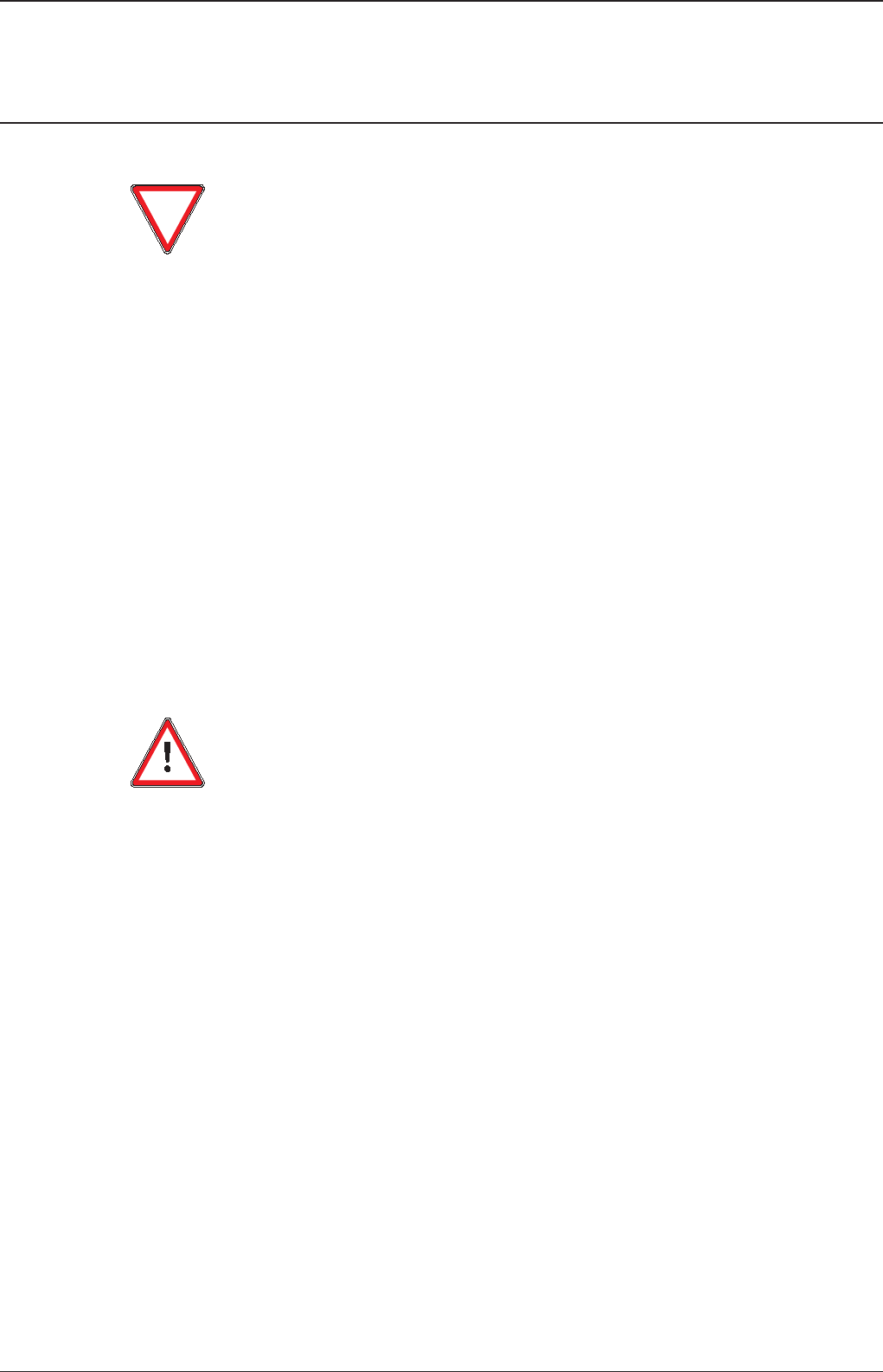
Mounting
The switch mode power supply can be snapped on a DIN rail according
to IEC/EN 60715 as shown in the accompanying picture. For that
the device is set with its mounting rail slide on the upper edge of the
mounting rail and locked by lifting it downwards.
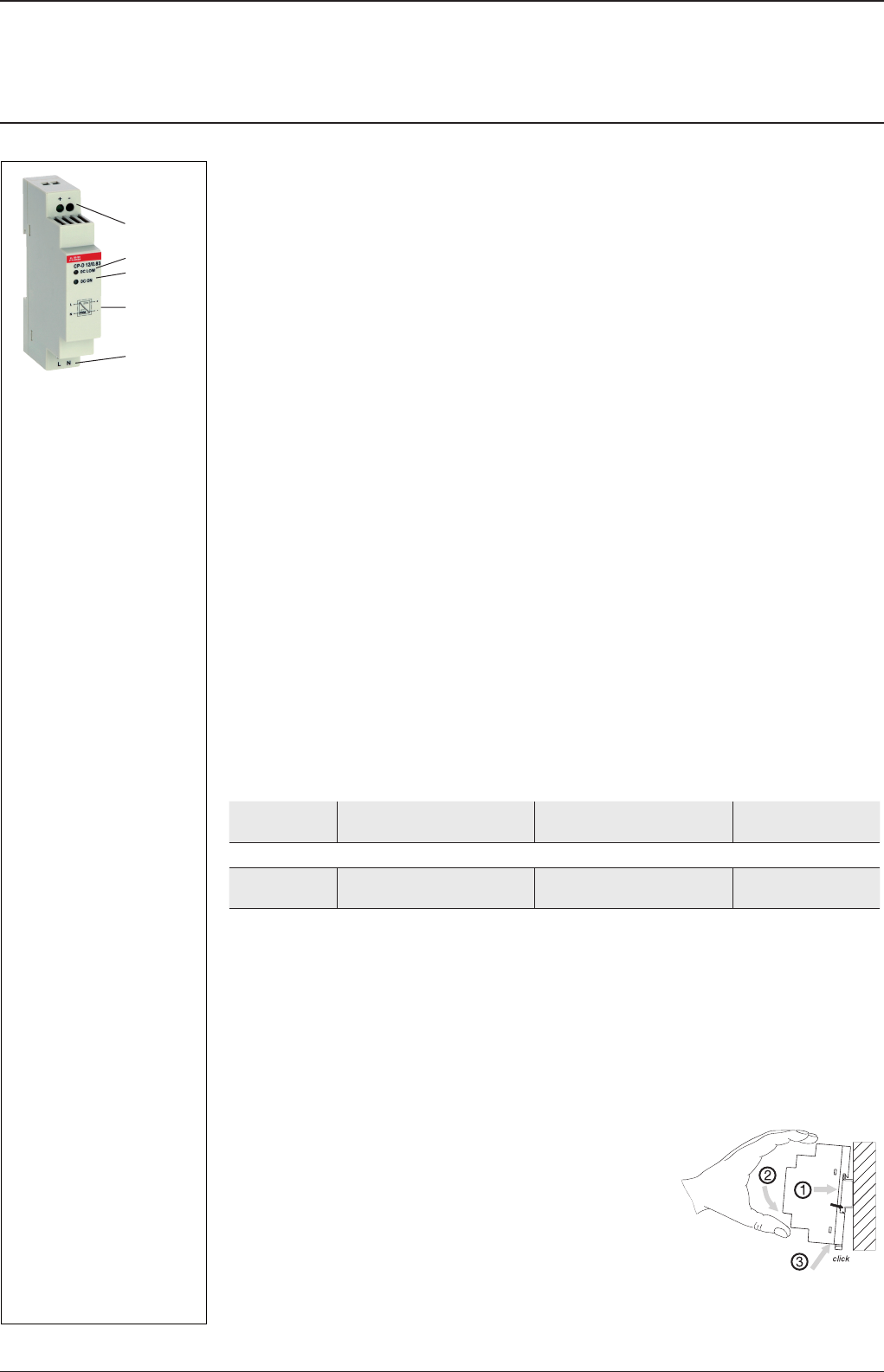
2CDC 271 024 F0t07
a OUTPUT +, ‑:
terminals ‑ output
b INPUT L, N:
terminals ‑ input
c DC ON: green LED ‑
output voltage applied
d DC LOW: red LED ‑
output voltage too low
e Circuit diagram
2CDC 272 040 F0b07
Power supply CP-D 12/0.83
Primary switch mode power supply
Data sheet

2ABB
Installation
Demounting
Remove the switch mode power supply as shown in the accompanying
picture. For that the latching lever is pulled downwards by means of the
screwdriver. Alternatively you can press the unlock button to release the
device. Then in both cases the device can be unhinged from the mounting
rail edge and removed.
Mounting position
The devices have to be mounted horizontally with the input terminals
on the bottom. In order to ensure a sufficient convection, the minimum
distance to other modules should not be less than 25 mm in vertical
direction and horizontal direction.
Electrical connection
Connect the input terminals L and N. The installation must be executed acc. to EN 60950, provide a
suitable disconnecting device (e. g. line protection switch) in the supply line. The input side is protected
by an internal input fuse.
Rate the lines for the maximum output current or provide a separate fuse protection. We recommend to
choose the cable section as large as possible in order to minimize voltage drops. Observe the polarity.
Actuate plug connector only when power is off. The device is overload, short‑circuit and open‑circuit
proof. The secondary side of the power supply is electrically isolated from the input and internally not
earthed (SELV) and can therefore be earthed by the user according to the needs with + or ‑ (PELV).
Connection diagram(s)
+, ‑ Output voltage
L, N Input voltage
2CDC 272 041 F0b07
2CDC 272 042 F0b07
+-
NL
-
+
L
N
PWM
2CDC 272 038 F0b07
Power supply CP-D 12/0.83
Primary switch mode power supply
Data sheet
3
ABB
Safety instructions and warnings
The device must be installed by qualified persons only and in accordance with the specific national
regulations (e. g. VDE, etc.).
CP‑D power supplies are chassis‑mounted units. They are maintenance‑free and do not contain any
integral
setting elements and should therefore not be opend.
Before any installation, maintenance or modification work:
Disconnect the system from the supply network and protect against switching on!
Before start of operation the following must be ensured:
Connect to main according to the specific national regulations.
Power supply cables and unit must be sufficiently fused. A disconnecting device has to be provided
for the end product to disengage unit and supply cables from supply mains if required.
Rate the output lines for the output current of the power supply and connect them with the correct
polarity.
In order to ensure sufficient air‑cooling the distance to the other devices has to be considered.
Attention! Improper installation/operation may impair safety and cause operational difficulties or
destruction of the unit.
In operation pay attention to:
Do not modify the installation (primary and secondary side)! High current! Risk of electric arcs and
electric shock (danger to life)!
Risk of burns: Depending on the operation conditions the enclosure can become very hot.
If the internal fuse blows, most probably the device is defect. In this case, an examination of the
switch mode power supply by the manufacturer is necessary.
Attention! Danger to life!
Disconnect the system from the supply network before executing any works at the device and protect
against switching on!
The power supply contains components with high stored energy and circuits with high voltage! Do not
introduce any objects into the unit and do not open the unit.
With some units of this range the output is capable of providing hazardous energy. Ensure that the
service personnel is protected against inadvertent contact with parts carrying energy.
Power supply CP-D 12/0.83
Primary switch mode power supply
Data sheet

4ABB
Technical data
Data at Ta = 25 °C, Uin = 230 V AC and rated values, unless otherwise indicated
Input circuits - Supply circuits 1SVR 427 041 R1000
Rated input voltage Uin L, N 100‑240 V AC
Typical input current / power consumption 110 V AC 230 V AC
200 mA / 12.68 W 128.3 mA / 13.01 W
100‑240 V AC
Input voltage range AC 90‑264 V AC
DC 120‑375 V DC
Frequency range AC 47‑63 Hz
Inrush current limiting 30 A max. 3 ms
Power failure buffering time min. 30 ms
Internal input fuse (apparatus protection, not accessible) 1 A slow‑acting / 250 V AC
Power factor correction (PFC) no
Indication of operational states 1SVR 427 041 R1000
Output voltage DC ON: green LED V: output voltage applied
DC LOW: red LED V: output voltage too low
Output circuits 1SVR 427 041 R1000
Rated output voltage +, ‑ 12 V DC
Tolerance of the output voltage ± 1 %
Rated output power 10 W
Rated output current IrTa ≤ 60 °C 0.83 A
Derating of the output current 60 °C < Ta ≤ 70 °C 2.5 %/°C
Deviation load change statical max. 1 %
change of output voltage
within the input voltage range
max. 1 %
Control time < 1 ms
Starting time after applying supply voltage at Ir1000 ms
Rise time at rated load typ. 1 ms
Residual ripple and switching peaks BW = 20 MHz 50 mV
Parallel connection yes, use of CP‑D RU required
Series connection yes, to increase voltage
Resistance to reverse feed 18 V / 1 s
Characteristic curve of output U/I characteristic curve
Short‑circuit protection continuous short‑circuit stability
Short‑circuit behaviour continuation with output power limiting
Current limiting at short circuit typ. 1.4 A
Overload protection output power limiting
Overvoltage protection 15‑16.5 V DC
No‑load protection continuous no‑load stability
Starting of capacitive loads unlimited
General data 1SVR 427 041 R1000
Duty time 100 %
Dimensions (W x H x D) 18 x 91 x 57.5 mm
(0.71 x 3.58 x 2.26 inches)
Material of housing housing Plastic
Power supply CP-D 12/0.83
Primary switch mode power supply
Data sheet

5
ABB
General data 1SVR 427 041 R1000
Efficiency typ. 78 %
Weight 0.066 kg (0.13 lb)
Mounting position horizontal
Minimum distance to other units
normal operation mode horizontal 25 mm (0.98 inch)
vertical 25 mm (0.98 inch)
Mounting DIN rail (IEC/EN 60715),
snap‑on mounting without any tool
Degree of protection housing / terminals IP20 / IP20
Class of protection II
Electrical connection 1SVR 427 041 R1000
Input circuit / Output circuit Screw connection
Wire size fine‑strand with wire end
ferrule
0.2‑1.5 mm2
(24‑16 AWG)
rigid 0.2‑2.5 mm2
(26‑12 AWG)
Stripping length 4‑5 mm (0.16‑0.2 in)
Tightening torque 0.6 Nm (5 lb.in)
Environmental data 1SVR 427 041 R1000
Ambient temperature range operation ‑40...+70 °C
full load ‑40...+60 °C
storage ‑40...+85 °C
Damp heat, cyclic (IEC/EN 60068‑2‑30) 4 x 24 h cycles, 40 °C, 95 % RH
Vibration, half‑sine (IEC/EN 60068‑2‑6) 50 m/s2, 10 Hz ‑ 2 kHz
Shock, half‑sine (IEC/EN 60068‑2‑27) 40 m/s2, 22 ms
Isolation data 1SVR 427 041 R1000
Rated isolation voltage Uiinput circuit / output circuit 3 kV AC
Pollution degree 2
Overvoltage category (UL/IEC/EN 60950‑1) II
Standards / Directives 1SVR 427 041 R1000
Product standard EN 61204
EMC Directive 2004/108/EC
Low Voltage Directive 2006/95/EC
Electrical safety UL 508, UL 60950‑1, EN 60950‑1
Protective low voltage SELV (EN 60950‑1)
Electromagnetic compatibility 1SVR 427 041 R1000
Interference immunity to IEC/EN 61000‑6‑2
electrostatic discharge IEC/EN 61000‑4‑2 Level 4 (4 kV / 8 kV)
radiated, radio‑frequency, electromagnetic field IEC/EN 61000‑4‑3 Level 3 (10 V/m)
electrical fast transient / burst IEC/EN 61000‑4‑4 Level 4 (4 kV)
surge IEC/EN 61000‑4‑5 Level 3 (2 kV L‑L)
conducted disturbances, induced by radio‑
frequency fields
IEC/EN 61000‑4‑6 Level 3 (10 V)
Power supply CP-D 12/0.83
Primary switch mode power supply
Data sheet

6ABB
Electromagnetic compatibility 1SVR 427 041 R1000
Interference emission IEC/EN 61000‑6‑3
high‑frequency radiated IEC/CISPR 22, EN 55022 Class B
high‑frequency conducted IEC/CISPR 22, EN 55022 Class B
Power supply CP-D 12/0.83
Primary switch mode power supply
Data sheet
7
ABB
Technical diagrams
Output behaviour
0
1
0
2
3
4
5
6
7
8
9
10
11
12
2CDC 272 019 F0207
Uout [V]
Iout [A]
0.50.25 0.751 1.25
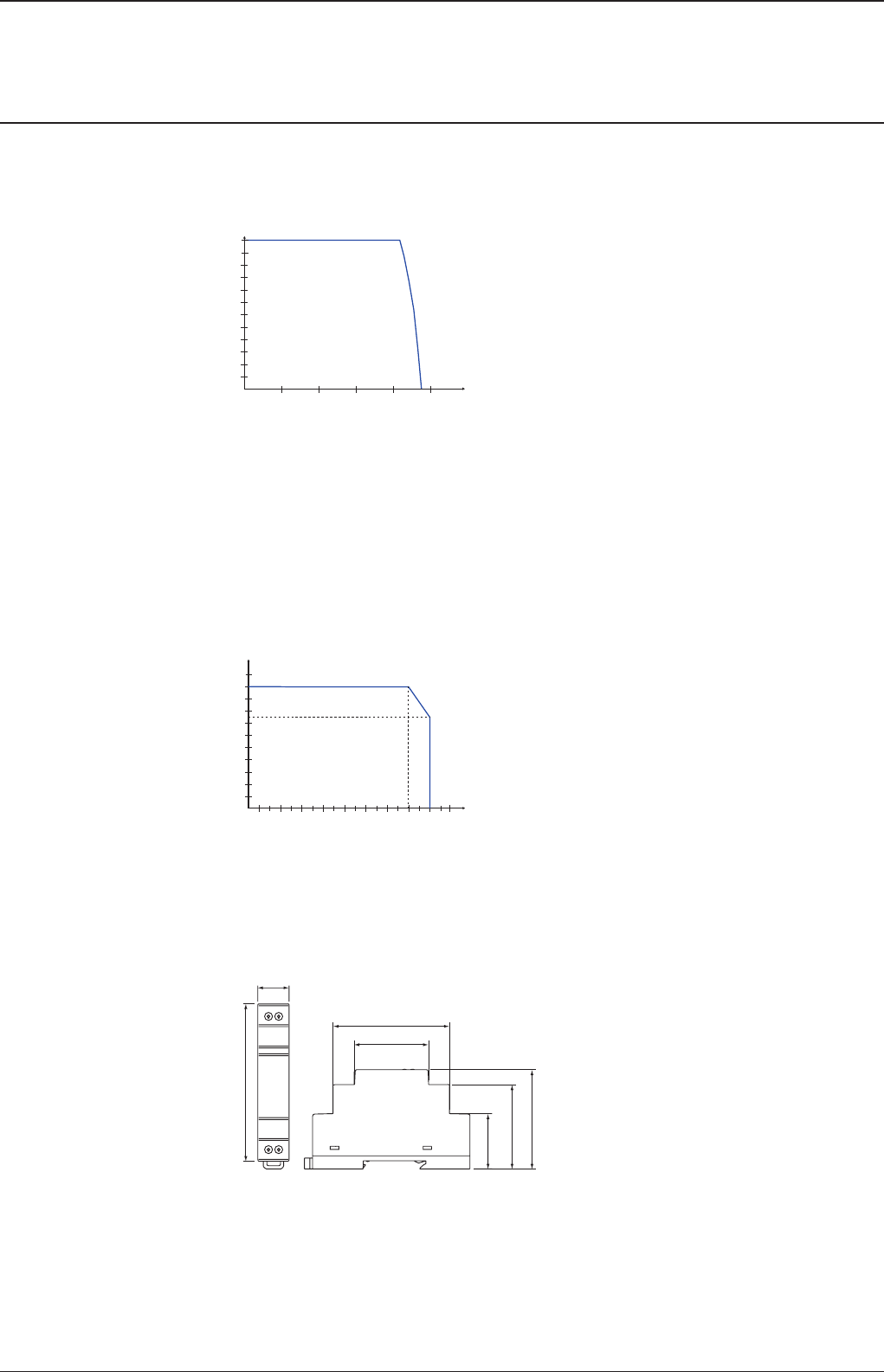
Characteristic curve of output at Ta = 25 °C
The switch mode power supply CP‑D 12/0.83 is able to supply at 12 V DC output voltage and
at an ambient temperature of:
≤ 60 °C a continuous output current of approx. 0.83 A
at ambient temperatures of:
60 °C < Ta ≤ 70 °C the output power has to be reduced by 2,5 % per °C temperature increase.
If the switch mode power supply is loaded with an output current > 0.83 A, the operating point is
passing through the U/I characteristic curve shown.
Temperature behaviour
-10 010203040506070
10
20
30
40
50
60
70
80
90
100
2CDC 272 018 F0207
P
out
[%]
Ta [°C]
Characteristic curve of temperature at Uout
Dimensions
in mm
CP-D 12/0.83
18,0 [0.71”]
67,0 [2.64”]
44,5 [1.75”]
91,0 [3.58”]
32,1 [1.26”]
57,5 [2.26”]
49,0 [1.93”]
2CDC 272 011 F0b07
Power supply CP-D 12/0.83
Primary switch mode power supply
Data sheet

8ABB
Further Documentation
Document title Document type Document number
Electronic Products and Relays Technical catalogue 2CDC 110 004 C02xx
Power Supply Units Application manual 2CDC 114 048 M020x
You can find the documentation on the internet at www.abb.com/lowvoltage R Control Products R Power Supplies
Power supply CP-D 12/0.83
Primary switch mode power supply
Data sheet
ABB STOTZ-KONTAKT GmbH
P. O. Box 10 16 80
69006 Heidelberg, Germany
Phone: +49 (0) 6221 7 01-0
Fax: +49 (0) 6221 7 01-13 25
E-mail: info.desto@de.abb.com
You can find the address of your
local sales organisation on the
ABB home page
http://www.abb.com/contacts
-> Low Voltage Products and Systems
Contact us
Note:
We reserve the right to make technical changes or
modify the contents of this document without prior
notice. With regard to purchase orders, the agreed
particulars shall prevail. ABB AG does not accept
any responsibility whatsoever for potential errors or
possible lack of information in this document.
We reserve all rights in this document and in the
subject matter and illustrations contained therein.
Any reproduction, disclosure to third parties or
utilization of its contents – in whole or in parts – is
forbidden without prior written consent of ABB AG.
Copyright© 2010 ABB
All rights reserved
Document number 2CDC 114 052 D0201 (02/12)
