Product Range Catalog CA04020001Z EN 127323 2
127323-Catalog 1 127323-Catalog_1 127323-Catalog_1 Batch9 unilog cesco-content
2014-10-22
: Pdf 127323-Catalog 2 127323-Catalog_2 Batch9 unilog
Open the PDF directly: View PDF ![]() .
.
Page Count: 177 [warning: Documents this large are best viewed by clicking the View PDF Link!]
- Product range catalog
- Table of contents
- DC1, DA1 variable frequency drives
- SVX, SPX variable frequency drive
- DS7 soft starters
- S801+/S811+ Soft Starters
- Rapid Link 4.0
- SmartWire-DT™
- Appendix
- Imprint
Changes to the products, to the information contained in this document, and to prices
are reserved; so are errors and omissions. Only order confirmations and technical documenta-
tion by Eaton is binding. Photos and pictures also do not warrant a specific layout or function-
ality. Their use in whatever form is subject to prior approval by Eaton. The same applies to
Trademarks (especially Eaton, Moeller, Cutler-Hammer). The Terms and Conditions of Eaton
apply, as referenced on Eaton internet pages and Eaton order confirmations.
DC1/DA1 and SVX/SPX variable frequency drives
DS7 and S801+/S811+ soft starters
Rapid Link 4.0 distributed, electronic drive system
Eaton is dedicated to ensuring that reliable, efficient and safe
power is available when it’s needed most. With unparalleled
knowledge of electrical power management across industries,
experts at Eaton deliver customized, integrated solutions to
solve our customers’ most critical challenges.
Our focus is on delivering the right solution for the application.
But, decision makers demand more than just innovative products.
They turn to Eaton for an unwavering commitment to personal
support that makes customer success a top priority. For more
information, visit www.eaton.eu.
To contact an Eaton salesperson or
local distributor/agent, please visit
www.eaton.eu/electrical/customersupport
Eaton Industries GmbH
Hein-Moeller-Str. 7–11
D-53115 Bonn / Germany
© 2012 by Eaton Corporation
All rights reserved
Printed in Germany 07/13
Publication No.: CA04020001Z_EN-INT
Doku/DHW/ip/MP 07/13
Article No.: 170504
Eaton is a registered trademark of Eaton
Corporation
All other trademarks are property of their
respective owners.
SmartWire-DT® is a registered trademark of
Eaton Corporation.
Product range catalog for variable frequency drives, soft starters, Rapid Link
Product range catalog
Efficient Engineering for
starting and controlling motors.
CA04020001Z-EN-INT_Umschlag.indd 4-6CA04020001Z-EN-INT_Umschlag.indd 4-6 09.07.13 13:1909.07.13 13:19

18741833 1886 1911 19141893 198319621961 1989198419771908190618991897 1963 19671934
The power of fusion.
There’s a certain energy at Eaton. It’s the power of uniting some of the
world’s most respected names to build a brand you can trust to meet
your every power management need.
Eaton is dedicated to ensuring that reliable, effi cient and safe power
is available when it’s needed most. Building on over 100 years of
experience in electrical power management, the experts at Eaton
deliver customized, integrated solutions to solve your most critical
challenges. To learn more visit www.eaton.eu/electrical.
All of the above are trademarks of Eaton or its affi liates.
Eaton has a license to use the
Westinghouse brand name in Asia Pacifi c. ©2013 Eaton.
You can find comprehensive up-to-date product information at http://ecat.moeller.net
Lookup
You can search by keywords, product names, article numbers,
technical data: The search understands everything and takes
you straight to the product you’re looking for.
Graphical navigation
Graphical representation of the fields of application and
product groups.
Selection aids
Tailored to the typical expert’s approach, this search aid helps
you quickly find the product you need.
Data sheets
For every article the catalog can generate a technical data
sheet, which you can convert to a PDF file for printing or
saving with a single click.
Parts lists
From your search results you can create a parts list that you
can then send to your Eaton sales partner as a query.
You can find comprehensive up-to-date
information about Eaton’s automation
products and switchgear in our Online
Catalog.
Eaton Online Catalog – find product
details quickly and efficiently!
HTML data sheet; can be saved as PDF file.
Parts list, e.g. for queries to Eaton Sales.
CA04020001Z-EN-INT_Umschlag.indd 7-9CA04020001Z-EN-INT_Umschlag.indd 7-9 09.07.13 13:2009.07.13 13:20
PowerXL™ DC1, DA1 variable frequency drives Page 4
9000X variable frequency drives: SVX, SPX Page 78
DS7 soft starters Page 104
S801+, S811+ soft starters Page 132
Rapid Link distributed, electronic drive system Page 152
SmartWire-DT™ communication system Page 178
Appendix Page 189
Table of contents
DC1, DA1 variable frequency
drives
SVX, SPX variable frequency
drives
S801+, S811+ soft startersRapid LinkSmartWire-DT™Appendix DS7 soft starters

Energizing a world
that demands more.
Powering business worldwide
As a global diversifi ed power management company,
we help customers worldwide manage the power
needed for buildings, aircraft, trucks, cars, machinery
and businesses.
Eaton’s innovative technologies help customers manage
electrical, hydraulic and mechanical power more reliably,
effi ciently, safely and sustainably.
Discover today’s Eaton.
Unbenannt-1 2 25.04.13 11:24

We deliver:
s Electrical solutions that use less energy, improve power reliability
and make the places we live and work safer and more comfortable
s Hydraulic and electrical solutions that enable machines
to deliver more productivity without wasting power
s Aerospace solutions that make aircraft lighter, safer and less
costly to operate, and help airports operate more efficiently
s Vehicle drivetrain and powertrain solutions that deliver
more power to cars, trucks and buses, while reducing fuel consumption
and emissions
We provide integrated
solutions that help make
energy, in all its forms,
more practical and
accessible.
With 2012 sales of
$16.3 billion, Eaton
has approximately
103,000 employees
around the world and
sells products in more
than 175 countries.
Eaton’s electrical business
Eaton is a global leader with expertise in:
s 0OWERDISTRIBUTIONANDCIRCUITPROTECTION
s "ACKUPPOWERPROTECTION
s 3OLUTIONSFORHARSHANDHAZARDOUSENVIRONMENTS
s ,IGHTINGANDSECURITY
s 3TRUCTURALSOLUTIONSANDWIRINGDEVICES
s #ONTROLANDAUTOMATION
s %NGINEERINGSERVICES
%ATONISPOSITIONEDTHROUGHITSGLOBALSOLUTIONSTOANSWER
TODAYSMOSTCRITICALELECTRICALPOWERMANAGEMENTCHALLENGES
7ITHYEARSOFELECTRICALEXPERIENCEBEHINDUSWERE
ENERGIZEDBYTHECHALLENGEOFPOWERINGUPAWORLDTHAT
DEMANDSTWICEASMUCHENERGYASTODAY7EREANTICIPATING
NEEDSENGINEERINGPRODUCTSANDCREATINGSOLUTIONSTO
ENERGIZEOURMARKETSTODAYANDINTHEFUTURE
7EAREDEDICATEDTOENSURINGTHATRELIABLEEFFICIENTANDSAFE
POWERISAVAILABLEWHENITSNEEDEDMOST
waton.ww.e eu
Unbenannt-1 3 25.04.13 11:24

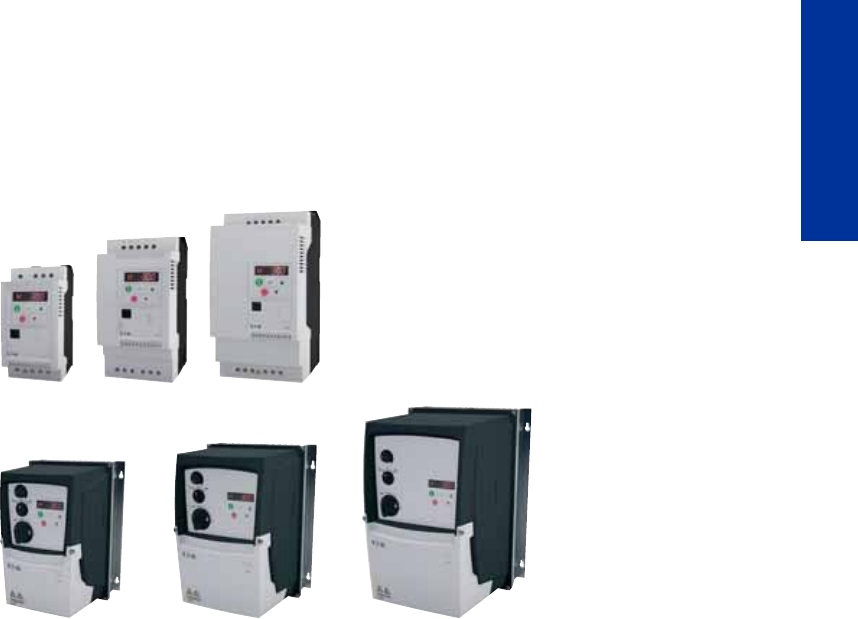
Variable frequency drives make it possible to use infinitely variable speed control with
three-phase asynchronous motors and AC motors. To do so, they convert a single-phase
or three-phase alternating voltage with a specific frequency and amplitudes into a single-
phase or three-phase alternating voltage with a variable frequency and a variable ampli-
tude. With its DC1 and DA1 device series, Eaton has just the right variable frequency
drive for any machine building application or standard electric drive system application,
regardless of whether your needs are extremely simple or extremely complex.
DC1 variable frequency drives
Output voltage with sinusoidal pulse-width modulation (PWM) when using Volts-per-Hertz con-
trol (V/Hz control) with slip compensation and start voltage boost.
DC1-12…: UIN 1~230 V/UOUT 3~230 V, allocated motor output 0.37 – 4 kW
DC1-32…: UIN 3~230 V/UOUT 3~230 V, allocated motor output 0.37 – 4 kW
DC1-34…: UIN 3~400 V/UOUT 3~400 V, allocated motor output 0.75 – 11 kW
DC1-S2…: UIN 1~230 V/UOUT 1~230 V, allocated motor output 0.37 – 1.1 kW (Single-phase
motor)
DC1-S1…: UIN 1~115 V/UOUT 1~115 V, allocated motor output 0.37 – 0.55 kW
DC1-1D…: UIN 1~115 V/UOUT 3~230 V, allocated motor output 0.37 – 1.1 kW (voltage doubler)
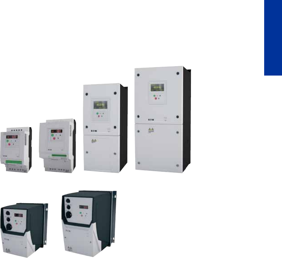
DA1 variable frequency drives
Output voltage with sinusoidal pulse-width modulation (PWM) when using Volts-per-Hertz con-
trol (V/Hz control), sensorless (SLVC) and sensored vector control
DA1-12…: UIN 1~230 V/UOUT 3~230 V, allocated motor output 0.75 – 2.2 kW
DA1-32…: UIN 3~230 V/UOUT 3~230 V, allocated motor output 0.75 – 75 kW
DA1-34…: UIN 3~400 V/UOUT 3~400 V, allocated motor output 0.75 – 250 kW
PowerXL™ DC1, DA1 variable frequency
drives
PowerXL™ variable frequency drives
CA04020001Z-EN-INT www.eaton.eu
5
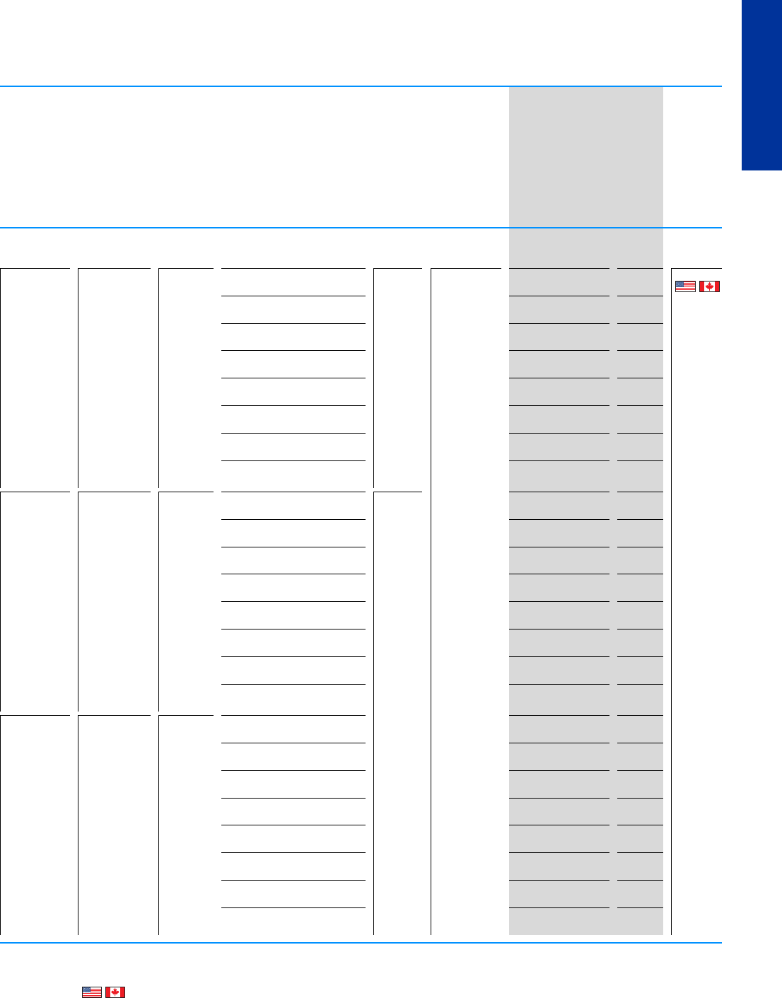
DC1, DA1
System overview
variable frequency drives DC1 6
Description
variable frequency drives DC1 7
System overview
variable frequency drives DA1 8
Description
variable frequency drives DA1 9
Technical overview
variable frequency drives DC1, DA1 10
Key to type references, Sizes and degree of protection UL/CSA
variable frequency drives DC1 11
Ordering
variable frequency drives DC1 14
Key to type references UL/CSA
variable frequency drives DA1 18
Sizes and degree of protection
variable frequency drives DA1 19
Ordering
variable frequency drives DA1 20
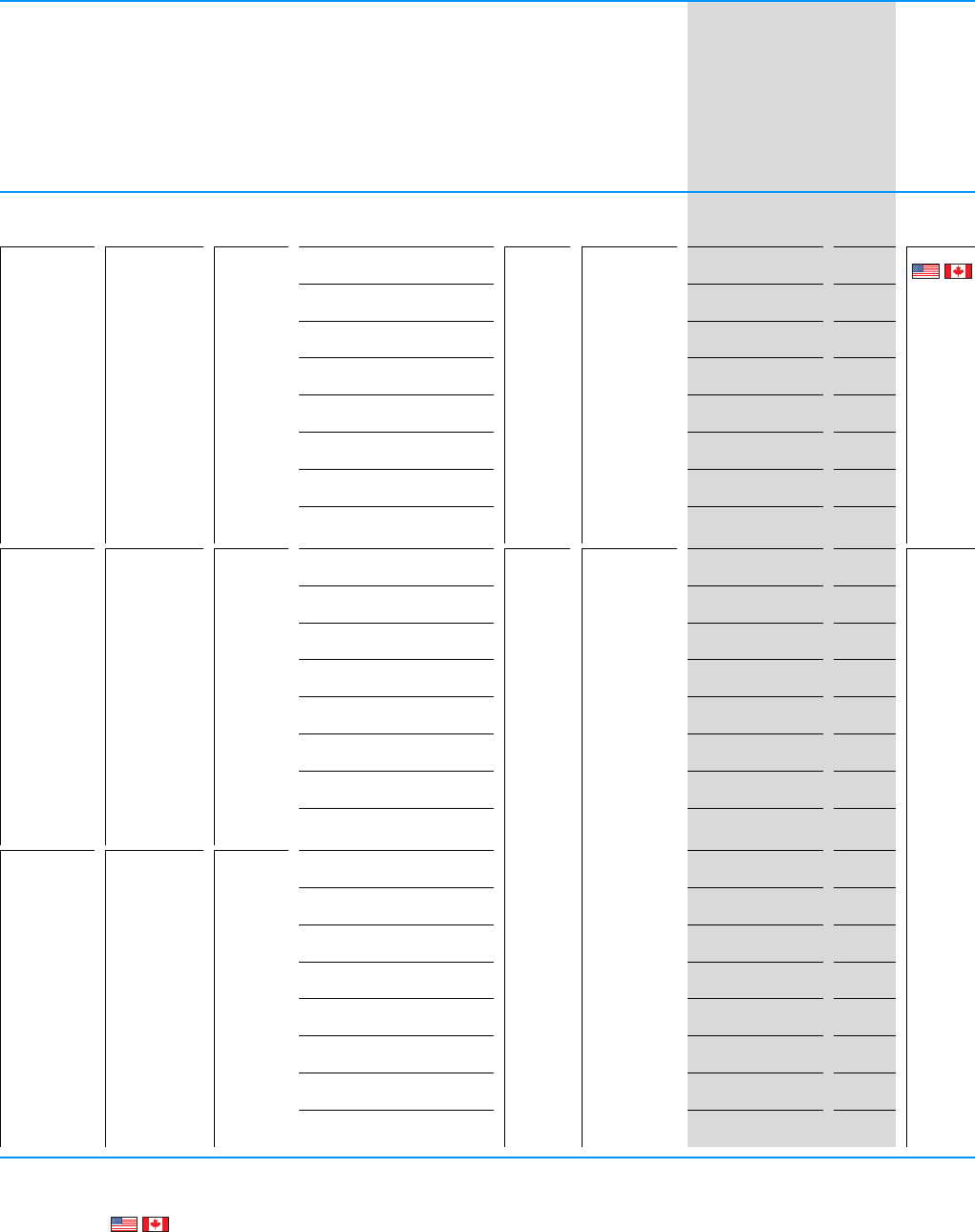
Accessories 31
Braking resistances 34
Mains choke, motor chokes 36
Engineering
Assigned switching and protective elements 39
General information on Engineering 40
Connection example for DC1 42
Assigned switching and protective elements 44
Technical data
variable frequency drives DC1 48
variable frequency drives DA1 54
Mains choke, motor chokes 62
Dimensions
variable frequency drives DC1 64
variable frequency drives DA1 65
Accessories 68
Mains choke, motor chokes 70
Sine filters 72
Braking resistances 74
6 PowerXL™ variable frequency drives
DC1
CA04020001Z-EN-INT www.eaton.eu
DC1
System overview
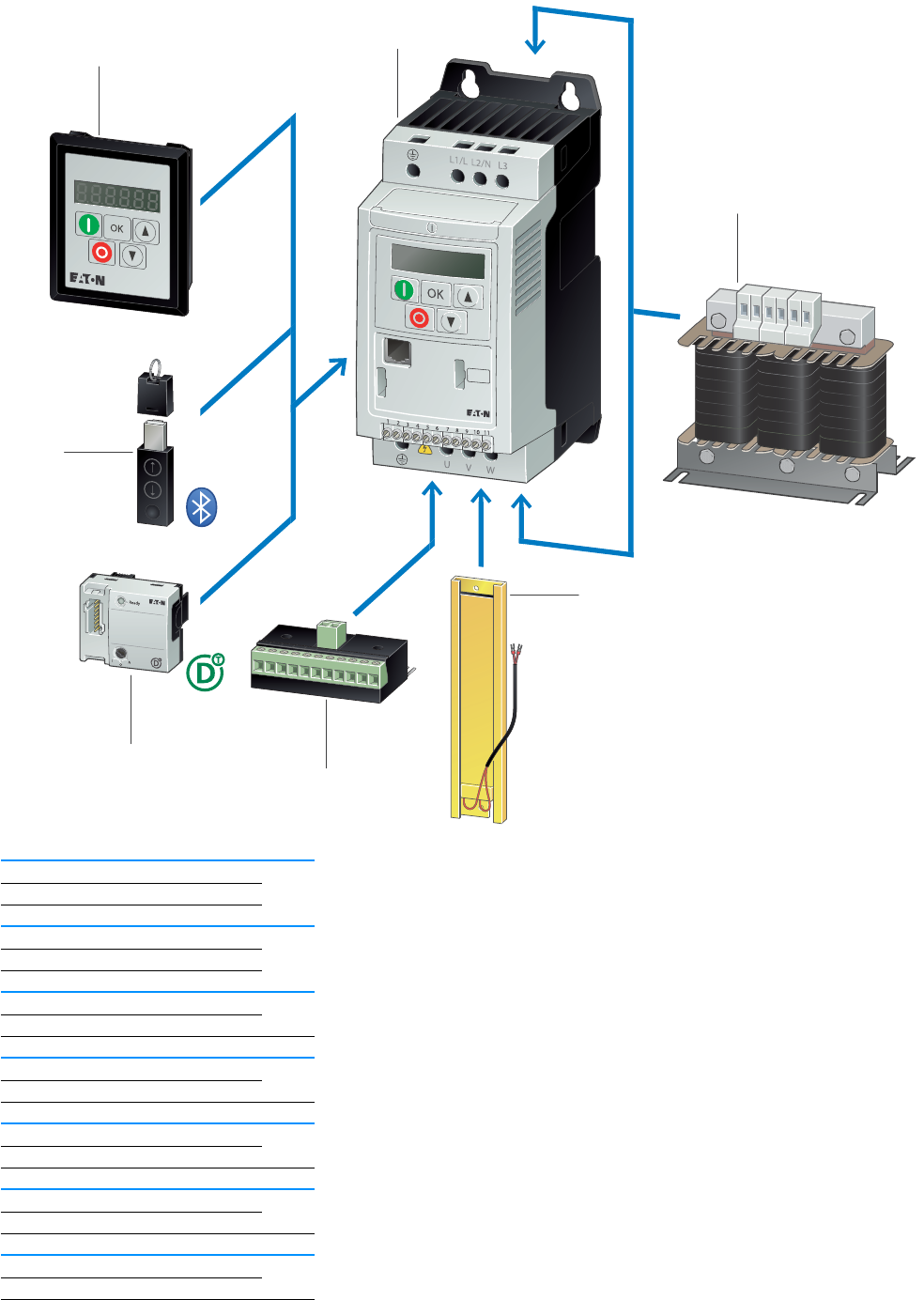
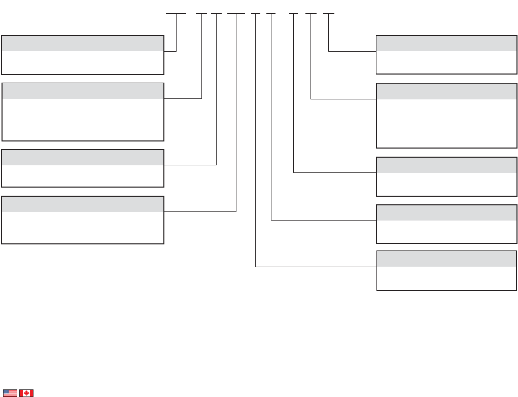
DC1 with IP20 degree of protection
DC1 variable frequency drive 1
page 12
Mains choke, motor choke, sine filter 2
page 36, page 37
Braking resistance 3
page 34
Expansion modules 4
page 33
SmartWire-DT module 5
page 33
Bluetooth communications stick 6
page 31
External Keypad 7
page 31
2
3
6
4
5
7
1
CA04020001Z-EN-INT www.eaton.eu
PowerXL™ variable frequency drives
DC1
7
DC1, DA1
DC1
Description
The DC1 is Eaton's compact variable frequency drive. It has been specifically
designed for simple applications. With only 14 basic parameters and
outstanding ease of mounting and installation, the DC1 is perfect for quick
commissioning. This makes these compact variable frequency drive ideal for
series production applications in the field of machine building.
Typical applications for this series include fans, pumps, and conveyor
systems. In addition, additional parameters and functionalities can be flexibly
enabled in order to allow the DC1 to handle more demanding applications as
well.
When configured with an IP66 degree of protection, DC1 variable frequency
drives can be installed in humid and wet locations as well.
In addition, these variable frequency drives can also be used as stand-alone
units directly on site if they are equipped with a setpoint potentiometer, a
selector switch, and a mains transfer switch and are configured with an IP66
degree of protection.
Essential features Accessory consideration
• Fast commissioning with 14 basic parameters
• Performance range (allocated motor output)
– 0.37 - 4 kW (UIN: 1~ 230 V / UOUT: 3~ 230 V)
– 0.37 - 4 kW (UIN: 3~ 230 V / UOUT: 3~ 230 V)
– 0.75 - 11 kW (UIN: 3~ 400 V / UOUT: 3~ 400 V), up to 7.5 kW at IP66
– 0.37 - 1.1 kW (UIN: 1~230 V / UOUT: 1~230 V), single-phase motor
– 0.37 - 0.55 kW (UIN: 1~ 115 V / UOUT: 1~ 115 V), single-phase motor
– 0.37 - 1.1 kW (UIN: 1~ 115 V / UOUT: 3~ 230 V) with voltage doubler
• Large overload capability: 150% for 60 seconds, 175% for 2 seconds
• Maximum ambient temperature:
50 °C without derating (IP20) / 40 °C (IP66)
• Integrated® CANopen and Modbus
• Degree of protection to IP20 and IP66
•EMC filter
• Optional internal braking transistor for IP20 degree of protection
• Integrated PI controller
• V/Hz control with start voltage boost and slip compensation
• International standards (CE, UL, cUL, C-Tick, UkrSEPRO, RoHS)
• Side-by-side mounting
• SmartWire-DT field bus module
• I/O expansion with plug-in modules
• External keypad for control panel door
• Mains choke
• Motor choke
• sine filter
• braking resistances

8 PowerXL™ variable frequency drives
DA1
CA04020001Z-EN-INT www.eaton.eu
DA1
System overview
DA1 with IP20 degree of protection
DA1 variable frequency drives 1
page 20
Mains choke, motor choke, sine filter 2
page 36, page 37
Braking resistance 3
page 34
Fieldbus modules 4
page 33
Bluetooth communications stick 5
page 31
External Keypad 6
page 31
2
3
5
4
6
1
CA04020001Z-EN-INT www.eaton.eu
PowerXL™ variable frequency drives
DA1
9
DC1, DA1
DA1
Description
DA1 frequency inverters are ideal for demanding, speed-dependent
applications. Their wide performance range of up to 250 kW, together with
their compact dimensions and high level of functionality, are sure to leave a
lasting impression. Accordingly, DA1 units come with an integrated EMC filter
and braking transistor. Moreover, the Modbus RTU and CANopen protocols
are integrated as standard.®. With sensorless vector control, DA1 variable
frequency drives are able to provide 200% torque at zero rpm. This makes them
the perfect choice for applications that involve lifting or tractive forces.
Comprehensive expansions such as additional inputs and outputs (analog,
digital) and various field bus modules round off this variable frequency drive's
flexibility.
When configured with an IP66 degree of protection, DA1 variable frequency
drives can be installed in humid and wet locations as well.
In addition, these variable frequency drives can also be used as stand-alone
units directly on site if they are equipped with a setpoint potentiometer,
a selector switch, and a mains transfer switch.
Essential features Accessory consideration
• Performance range:
– 0.75 - 2.2 kW (UIN: 1~ 230 V / UOUT: 3~ 230 V)
– 0.75 - 75 kW (UIN: 3~ 230 V / UOUT: 3~ 230 V)
– 0.75 - 250 kW (UIN: 3~ 400 V / UOUT: 3~ 400 V)
• Large overload capability: 150% for 60 seconds, 200% for 4 seconds
• Degrees of protection
– IP20 to 11 kW at 400 V
– IP40 at 200/250 kW at 400 V
– IP55 for 11 to 160 kW with 400 V
– IP66 up to 7.5 kW with 400 V; 0.75–4 kW with 230 V
• The maximum allocated motor output is 7.5 kW with degree of protection
IP66.
• Integrated® CANopen and Modbus
• EMC filter, integrated
• Braking transistor, integrated
• Control method: V/Hz control, sensorless vector control, vector control with
encoder
• Safe Torque Off (STO)
• Can be used to drive high-efficiency PM motors
• International standards (CE, UL, cUL, C-Tick, UkrSEPRO, RoHS)
• Side-by-side mounting
• Ambient air temperature 50 °C without derating (IP20), max. 40 °C (IP66)
• Master/Slave functionality
• SmartWire-DT field bus module
• Field bus modules (PROFIBUS, PROFINET, Ethernet/IP, EtherCat,
Modbus TCP, BACnet, and DeviceNet)
• I/O expansion with plug-in modules
• External keypad for control panel door
• High-resolution OLED display
• Mains choke
• Motor chokes
• sine filter
• braking resistances

10 PowerXL™ variable frequency drives
DC1, DA1
CA04020001Z-EN-INT www.eaton.eu
DC1, DA1
Technical overview
DC1... DA1...
Rated operational voltage Ue
115 V AC, single-phase -
230 V AC, 1-phase
230 V AC, 3-phase
400 V AC, 3-phase
Supply frequency fLN Hz 50/60 50/60
Rated operational current IeA2.3 - 24 2.2 - 450
Overload current for 60 s every 600 s IL%150 150
Starting current for 2 s IL%175 -
Starting current for 4 s IL% - 200
Assigned motor rating
at 115 V, 50 Hz P kW 0.37 - 0.55 (Single-phase motors) -
at 230 V, 50 Hz P kW 0.37 - 4 (0.37 - 4 for single-phase motors) 0.75 - 75
at 400 V, 50 Hz P kW 0.75 - 11 0.75 - 250
Ambient temperature
Operation °C
IP20/NEMA 0 -10 - +50 -10 - +50
IP40 --10 - +30
IP55/NEMA 3 --10 - +40 / -10 - +30 (Ie > 180 A)
IP66/NEMA 4X -10 - +40 -10 - +40
Storage °C -40 - +60 -40 - +60
Operation Mode
U/f control
Slip compensation
sensorless vector control (SLV) -
Vector control with feedback (CLV) -
Switching frequency fPWM kHz 4 - 32 4 - 32
Output voltage with VeU2
115 V AC, single-phase -
230 V AC, single-phase -
230 V AC, 3-phase
400 V AC, 3-phase
Output Frequency f2Hz 0 - 50 Hz (max. 500 Hz) 0 - 50 Hz (max. 500 Hz)
Protection type
IP20/NEMA 0
IP40 -
IP55/NEMA 3 -
IP66/NEMA 4X
Fitted with
Radio interference suppression filter
Brake chopper
Additional PCB protection -
7-digital display assembly
OLED display -
Interface OP-Bus (RS485)/Modbus RTU, CANopen® OP-Bus (RS485)/Modbus RTU, CANopen®
Fieldbus connection SmartWire-DT Ethernet IP
DeviceNet
PROFIBUS
PROFINET
Modbus-TCP
EtherCAT
BACnet/IP
SmartWire-DT
Analog inputs parameterizable, max. 2 x (0 - 10 V, 0/4 - 20 mA) parameterizable, max. 2 x (0 - 10 V, 0/4 - 20 mA)
Analog outputs parameterizable, max. 1 x (0 - 10 V) parameterizable, max. 2 x (0 - 10 V, 0/4 - 20 mA)
Digital inputs parameterizable, max. 4 x (max. 30 V DC) parameterizable, 3 x (max. 30 V DC)
Digital outputs parameterizable, max. 1 x (24 V DC) parameterizable, max. 2 x (24 V DC)
Relay outputs parameterizable, 1 x N/O, 6 A (250 V AC) / 5 A
(30 V DC)
parameterizable, 1 x N/O and 1 x changeover
contact, 6 A (250 V AC) / 5 A (30 V DC)
Production quality RoHS, ISO 9001 RoHS, ISO 9001
Safety functions -STO (Safe Torque Off)
Standards EMC: EN 61800-3:2004+A1-2012 EMC: EN 61800-3:2004+A1-2012
Certifications CE, cUL, UL, c-Tick, Ukr Sepro CE, cUL, UL, c-Tick, Ukr Sepro
PowerXL™ variable frequency drives
DC1
CA04020001Z-EN-INT www.eaton.eu
11
DC1, DA1
DC1
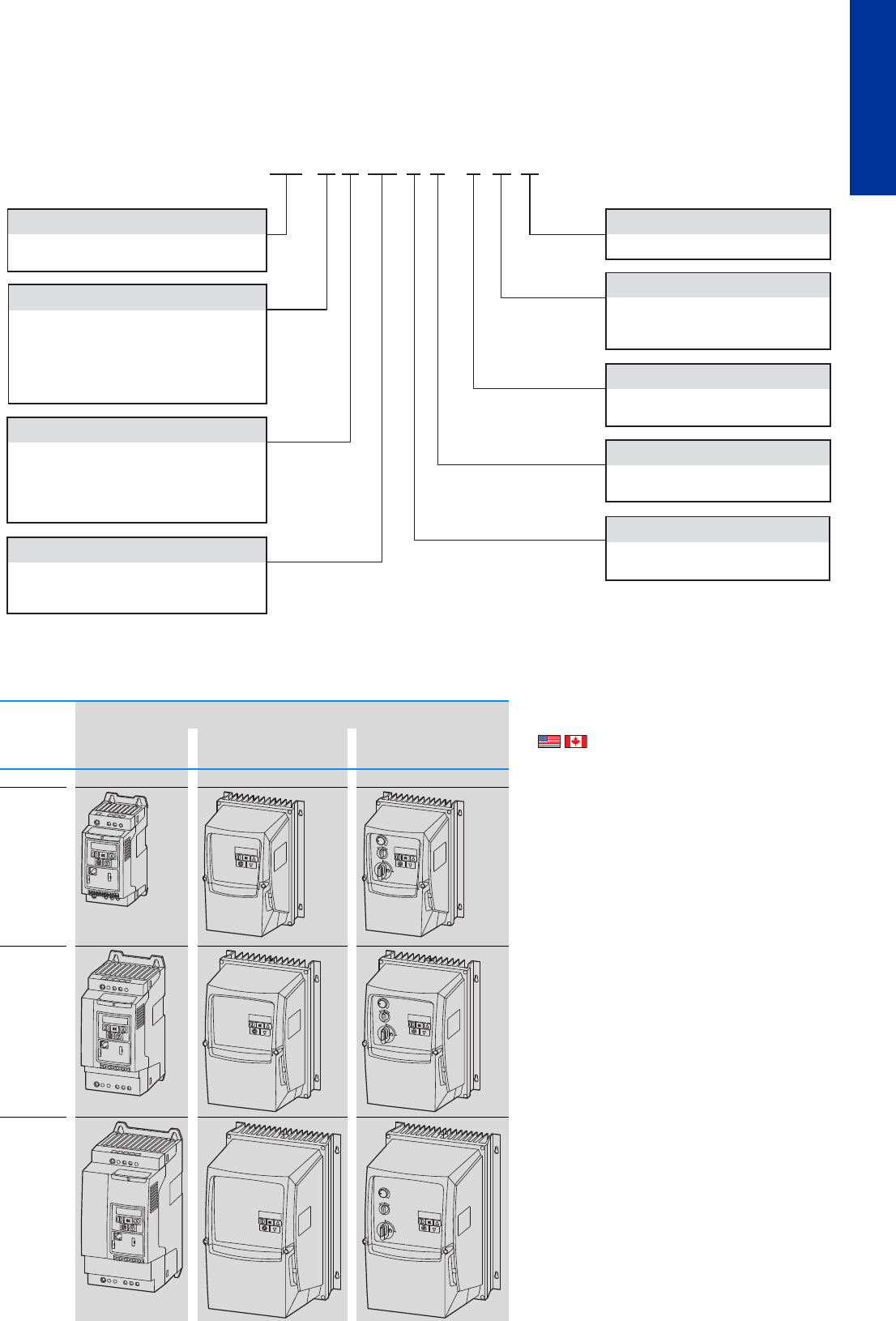
Key to type references
DC1
Sizes and degree of protection
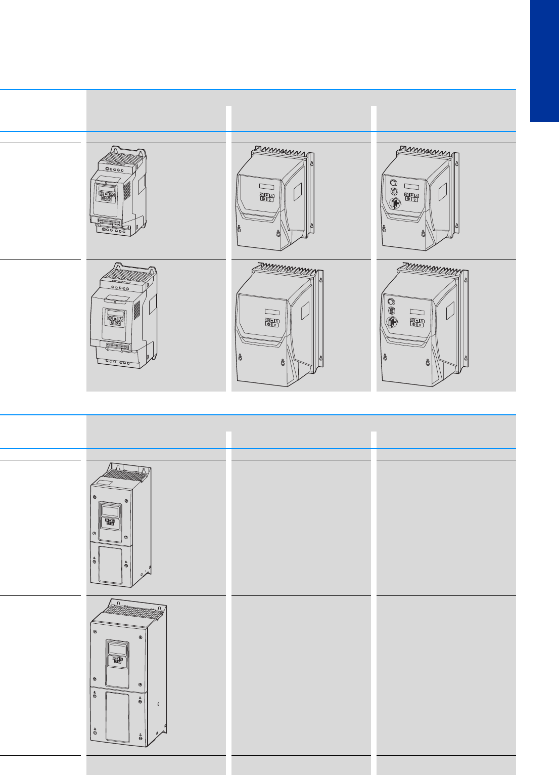
Frame size Protection type Information relevant for export to North America
IP20/NEMA 0 IP66/NEMA 4X IP66/NEMA 4X
Local controls
FS1 Product Standards UL 508C; CSA-C22.2 No. 14;
IEC/EN61800-3; IEC/EN61800-5;
CE marking
UL File No. E172143
UL Category Control No. NMMS, NMMS7
CSA File No. UL report applies to both US
and Canada
CSA Class No. 3211-06
North America
Certification UL listed, certified by UL for use
in Canada
Suitable for Branch circuits
Max. Voltage Rating 1~ 120 V AC IEC: TN-S UL/CSA:
"Y" (Solidly Grounded Wey)
1~ 240 V AC IEC: TN-S UL/CSA:
"Y" (Solidly Grounded Wey)
3~ 240 V AC IEC: TN-S UL/CSA:
"Y" (Solidly Grounded Wey)
3~ 480 V AC IEC: TN-S UL/CSA:
"Y" (Solidly Grounded Wey)
FS2
FS3
DC1 - 1 2 4D1 F N - A 20 N
Connection in power section
1 = single-phase mains connection/
three-phase motor connection
3 = three-phase mains connection/
three-phase motor connection
S = single-phase mains connection/
single-phase motor connection
Mains voltage category
1 = 110 V (110 - 115 V ± 10 %)
2 = 230 V (200 - 240 V ± 10 %)
4 = 400 V (380 - 480 V ± 10 %)
D = 110 V input/230 V output
(voltage doubler)
Device series
DC1 = variable frequency drive, compact, series 1
(D = Drives, C = Compact, 1 = Series 1)
B = Brake chopper
N = no internal brake chopper
B = Brake chopper
Display unit (display)
A = LED display
Degree of protection
20 = IP20/NEMA 0
66 = IP66/NEMA 4X
6S = IP66 with switch/NEMA 4X, switched
Type
N = Standard basic device
N = no internal RFI filter
F = Internal RFI filter
EMC (radio interference suppression filter)
Rated operational current (examples)
2D2 = 2,2 A
4D1 = 4,1 A
024 = 24 A
⏚
L1/L L2/N L3
⏚
UVW
123456789
10
11
PWROFF
ON
REV FWD
0
⏚
L1/L L2/N L3
DC-
⏚
U
DC+ BR VW
123456789
10
11
PWROFF
ON
REV FWD
0
⏚
U
DC+ BR VW
⏚
L1/L L2/N L3
DC-
123456789
10
11
PWROFF
ON
REVFWD
0
UL/CSA
12 PowerXL™ variable frequency drives
DC1, for AC motors 115 V/230 V
CA04020001Z-EN-INT www.eaton.eu
DC1, for AC motors 115 V/230 V
Ordering
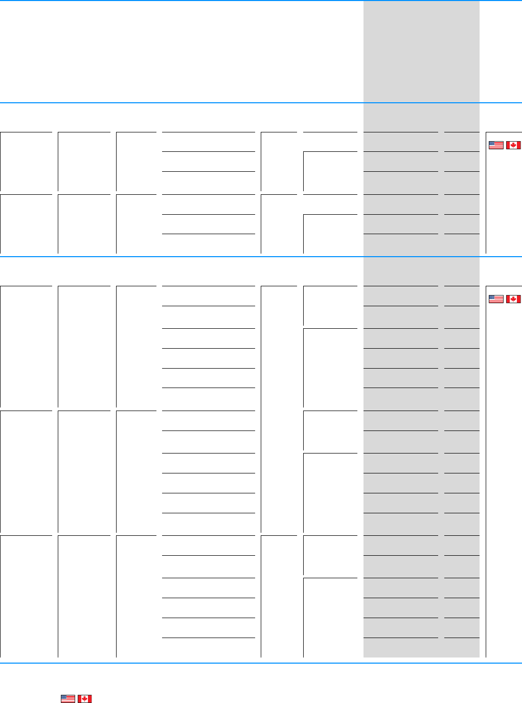
Rated
operational
current1)
Assigned motor
rating 2)
Rated motor
current
Fitted with Frame size Protection type Part no.
Article no.
Price
see price
list
Std. pack
IePI
e
Radio interference
suppression filter
Brake chopper
7-digital display
assembly
Local controls
AkWA
Ue 115 V AC, single-phase / U2 115 V AC, single-phase
Mains voltage (50/60Hz) ULN 110 (-10%) - 115 (+10%) V
Interface OP-Bus (RS485)/Modbus RTU, CANopen®
70.377--- FS1 IP20/NEMA 0 DC1-S17D0NN-A20N
169497
1off
--- IP66/NEMA 4X DC1-S17D0NN-A66N
169498
-- DC1-S17D0NN-A6SN
169499
10.5 0.55 10.5 - - FS2 IP20/NEMA 0 DC1-S1011NB-A20N
169500
-- IP66/NEMA 4X DC1-S1011NB-A66N
169501
- DC1-S1011NB-A6SN
169502
Ue 230 V AC, 1-phase / U2 230 V AC, single-phase
Mains voltage (50/60Hz) ULN 200 (-10%) - 240 (+10%) V
Interface OP-Bus (RS485)/Modbus RTU, CANopen®
4.3 0.37 4.3 - - - FS1 IP20/NEMA 0 DC1-S24D3NN-A20N
169512
1off
--DC1-S24D3FN-A20N
169521
--- IP66/NEMA 4X DC1-S24D3NN-A66N
169513
-- DC1-S24D3NN-A6SN
169514
--DC1-S24D3FN-A66N
169522
- DC1-S24D3FN-A6SN
169523
70.757--- IP20/NEMA 0 DC1-S27D0NN-A20N
169515
--DC1-S27D0FN-A20N
169524
--- IP66/NEMA 4X DC1-S27D0NN-A66N
169516
-- DC1-S27D0NN-A6SN
169517
--DC1-S27D0FN-A66N
169525
- DC1-S27D0FN-A6SN
169526
10.5 1.1 10.5 - - FS2 IP20/NEMA 0 DC1-S2011NB-A20N
169518
-DC1-S2011FB-A20N
169527
-- IP66/NEMA 4X DC1-S2011NB-A66N
169519
- DC1-S2011NB-A6SN
169520
-DC1-S2011FB-A66N
169528
DC1-S2011FB-A6SN
169529
Notes 1) Rated operational current at an operating frequency of 4 kHz and an ambient air temperature of +50°C
2) Assigned motor rating for normal internally and externally ventilated four-pole, three-phase asynchronous motors with 1500 rpm (at 50 Hz) or
1800 rpm (at 60 Hz)
Information relevant for export to North America page 11

PowerXL™ variable frequency drives
DC1, for three-phase motors 230 V
CA04020001Z-EN-INT www.eaton.eu
13
DC1, DA1
DC1, for three-phase motors 23 0 V
Rated
operational
current1)
Assigned motor
rating 2)
Rated motor
current
Fitted with Frame size Protection type Part no.
Article no.
Price
see price
list
Std. pack
IePI
e
Radio interference
suppression filter
Brake chopper
7-digital display
assembly
Local controls
AkWA
Ue 115 V AC, single-phase / U2 230 V AC, 3-phase
Mains voltage (50/60Hz) ULN 110 (-10%) - 115 (+10%) V
Interface OP-Bus (RS485)/Modbus RTU, CANopen®
2.3 0.37 2 - - - FS1 IP20/NEMA 0 DC1-1D2D3NN-A20N
169503
1off
--- IP66/NEMA 4X DC1-1D2D3NN-A66N
169504
-- DC1-1D2D3NN-A6SN
169505
4.3 0.75 3.2 - - - IP20/NEMA 0 DC1-1D4D3NN-A20N
169506
--- IP66/NEMA 4X DC1-1D4D3NN-A66N
169507
-- DC1-1D4D3NN-A6SN
169508
5.8 1.1 4.6 - - FS2 IP20/NEMA 0 DC1-1D5D8NB-A20N
169509
-- IP66/NEMA 4X DC1-1D5D8NB-A66N
169510
- DC1-1D5D8NB-A6SN
169511
Ue 230 V AC, 1-phase / U2 230 V AC, 3-phase
Mains voltage (50/60Hz) ULN 200 (-10%) - 240 (+10%) V
Interface OP-Bus (RS485)/Modbus RTU, CANopen®
2.3 0.37 2 - - - FS1 IP20/NEMA 0 DC1-122D3NN-A20N
169222
1off
--DC1-122D3FN-A20N
169240
--- IP66/NEMA 4X DC1-122D3NN-A66N
169223
-- DC1-122D3NN-A6SN
169224
--DC1-122D3FN-A66N
169241
- DC1-122D3FN-A6SN
169242
4.3 0.75 3.2 - - - FS1 IP20/NEMA 0 DC1-124D3NN-A20N
169225
--DC1-124D3FN-A20N
169243
--- IP66/NEMA 4X DC1-124D3NN-A66N
169226
-- DC1-124D3NN-A6SN
169227
--DC1-124D3FN-A66N
169244
- DC1-124D3FN-A6SN
169245
Notes 1) Rated operational current at an operating frequency of 4 kHz and an ambient air temperature of +50°C
2) Assigned motor rating for normal internally and externally ventilated four-pole, three-phase asynchronous motors with 1500 rpm (at 50 Hz) or
1800 rpm (at 60 Hz)
Information relevant for export to North America page 11

14 PowerXL™ variable frequency drives
DC1, for three-phase motors 230 V
CA04020001Z-EN-INT www.eaton.eu
Rated
operational
current1)
Assigned motor
rating 2)
Rated motor
current
Fitted with
Local controls
Frame size Protection type Part no.
Article no.
Price
see price
list
Std. pack
IePI
e
Radio interference
suppression filter
Brake chopper
7-digital display
assembly
AkWA
Ue 230 V AC, 1-phase / U2 230 V AC, 3-phase
Mains voltage (50/60Hz) ULN 200 (-10%) - 240 (+10%) V
Interface OP-Bus (RS485)/Modbus RTU, CANopen®
71.56.3--- FS1 IP20/NEMA 0 DC1-127D0NN-A20N
169228
1off
--DC1-127D0FN-A20N
169246
--FS2 DC1-127D0NB-A20N
169231
-DC1-127D0FB-A20N
169249
--- FS1 IP66/NEMA 4X DC1-127D0NN-A66N
169229
-- DC1-127D0NN-A6SN
169230
--DC1-127D0FN-A66N
169247
- DC1-127D0FN-A6SN
169248
--FS2 DC1-127D0NB-A66N
169232
- DC1-127D0NB-A6SN
169233
-DC1-127D0FB-A66N
169250
DC1-127D0FB-A6SN
169251
10.5 2.2 8.7 - - FS2 IP20/NEMA 0 DC1-12011NB-A20N
169234
-DC1-12011FB-A20N
169252
-- IP66/NEMA 4X DC1-12011NB-A66N
169235
- DC1-12011NB-A6SN
169236
-DC1-12011FB-A66N
169253
DC1-12011FB-A6SN
169254
15 4 14.8 - - FS3 IP20/NEMA 0 DC1-12015NB-A20N
169237
-- IP66/NEMA 4X DC1-12015NB-A66N
169238
- DC1-12015NB-A6SN
169239
Notes 1) Rated operational current at an operating frequency of 4 kHz and an ambient air temperature of +50°C
2) Assigned motor rating for normal internally and externally ventilated four-pole, three-phase asynchronous motors with 1500 rpm (at 50 Hz) or
1800 rpm (at 60 Hz)
Information relevant for export to North America page 11
PowerXL™ variable frequency drives
DC1, for three-phase motors 230 V
CA04020001Z-EN-INT www.eaton.eu
15
DC1, DA1
DC1, for three-phase motors 23 0 V
Rated
operational
current1)
Assigned motor
rating 2)
Rated motor
current
Fitted with Frame size Protection type Part no.
Article no.
Price
see price
list
Std. pack
IePI
e
Radio interference
suppression filter
Brake chopper
7-digital display
assembly
Local controls
AkWA
Ue 230 V AC, 3-phase / U2 230 V AC, 3-phase
Mains voltage (50/60Hz) ULN 200 (-10%) - 240 (+10%) V
Interface OP-Bus (RS485)/Modbus RTU, CANopen®
2.3 0.37 2 - - - FS1 IP20/NEMA 0 DC1-322D3NN-A20N
169255
1off
--- IP66/NEMA 4X DC1-322D3NN-A66N
169256
-- DC1-322D3NN-A6SN
169257
4.3 0.75 3.2 - - - IP20/NEMA 0 DC1-324D3NN-A20N
169258
--- IP66/NEMA 4X DC1-324D3NN-A66N
169259
-- DC1-324D3NN-A6SN
169260
71.56.3--- FS1 IP20/NEMA 0 DC1-327D0NN-A20N
169261
--FS2 DC1-327D0NB-A20N
169264
-DC1-327D0FB-A20N
169444
--- FS1 IP66/NEMA 4X DC1-327D0NN-A66N
169262
-- DC1-327D0NN-A6SN
169263
--FS2 DC1-327D0NB-A66N
169436
- DC1-327D0NB-A6SN
169437
-DC1-327D0FB-A66N
169445
DC1-327D0FB-A6SN
169446
10.5 2.2 8.7 - - FS2 IP20/NEMA 0 DC1-32011NB-A20N
169438
-DC1-32011FB-A20N
169447
-- IP66/NEMA 4X DC1-32011NB-A66N
169439
- DC1-32011NB-A6SN
169440
-DC1-32011FB-A66N
169448
DC1-32011FB-A6SN
169449
18 4 14.8 - - FS3 IP20/NEMA 0 DC1-32018NB-A20N
169441
-DC1-32018FB-A20N
169450
-- IP66/NEMA 4X DC1-32018NB-A66N
169442
- DC1-32018NB-A6SN
169443
-DC1-32018FB-A66N
169451
DC1-32018FB-A6SN
169452
Notes 1) Rated operational current at an operating frequency of 4 kHz and an ambient air temperature of +50°C
2) Assigned motor rating for normal internally and externally ventilated four-pole, three-phase asynchronous motors with 1500 rpm (at 50 Hz) or
1800 rpm (at 60 Hz)
Information relevant for export to North America page 11
16 PowerXL™ variable frequency drives
DC1, for three-phase motors 400 V
CA04020001Z-EN-INT www.eaton.eu
DC1, for three-phase motors 40 0 V
Rated
operational
current1)
Assigned motor
rating 2)
Rated motor
current
Fitted with Frame size Protection type Part no.
Article no.
Price
see price
list
Std. pack
IePI
e
Radio interference
suppression filter
Brake chopper
7-digital display
assembly
Local controls
AkWA
Ue 400 V AC, 3-phase / U2 400 V AC, 3-phase
Mains voltage (50/60Hz) ULN 380 (-10%) - 480 (+10%) V
Interface OP-Bus (RS485)/Modbus RTU, CANopen®
2.2 0.75 1.9 - - - FS1 IP20/NEMA 0 DC1-342D2NN-A20N
169453
1off
--DC1-342D2FN-A20N
169475
--- IP66/NEMA 4X DC1-342D2NN-A66N
169454
-- DC1-342D2NN-A6SN
169455
--DC1-342D2FN-A66N
169476
- DC1-342D2FN-A6SN
169477
4.1 1.5 3.6 - - - FS1 IP20/NEMA 0 DC1-344D1NN-A20N
169456
--DC1-344D1FN-A20N
169478
--DC1-344D1NB-A20N
169459
-DC1-344D1FB-A20N
169481
--- FS1 IP66/NEMA 4X DC1-344D1NN-A66N
169457
-- DC1-344D1NN-A6SN
169458
--DC1-344D1FN-A66N
169479
--FS2 DC1-344D1NB-A66N
169460
- DC1-344D1NB-A6SN
169461
- FS1 DC1-344D1FN-A6SN
169480
-FS2 DC1-344D1FB-A66N
169482
DC1-344D1FB-A6SN
169483
5.8 2.2 5 - - FS2 IP20/NEMA 0 DC1-345D8NB-A20N
169462
-DC1-345D8FB-A20N
169484
-- IP66/NEMA 4X DC1-345D8NB-A66N
169463
- DC1-345D8NB-A6SN
169464
-DC1-345D8FB-A66N
169485
DC1-345D8FB-A6SN
169486
Notes 1) Rated operational current at an operating frequency of 4 kHz and an ambient air temperature of +50°C
2) Assigned motor rating for normal internally and externally ventilated four-pole, three-phase asynchronous motors with 1500 rpm (at 50 Hz) or
1800 rpm (at 60 Hz)
Information relevant for export to North America page 11

PowerXL™ variable frequency drives
DC1, for three-phase motors 400 V
CA04020001Z-EN-INT www.eaton.eu
17
DC1, DA1
DC1, for three-phase motors 40 0 V
Rated
operational
current1)
Assigned motor
rating 2)
Rated motor
current
Fitted with Frame size Protection type Part no.
Article no.
Price
see price
list
Std. pack
IePI
e
Radio interference
suppression filter
Brake chopper
7-digital display
assembly
Local controls
AkWA
Ue 400 V AC, 3-phase / U2 400 V AC, 3-phase
Mains voltage (50/60Hz) ULN 380 (-10%) - 480 (+10%) V
Interface OP-Bus (RS485)/Modbus RTU, CANopen®
9.5 4 8.5 - - FS2 IP20/NEMA 0 DC1-349D5NB-A20N
169465
1off
-DC1-349D5FB-A20N
169487
-- IP66/NEMA 4X DC1-349D5NB-A66N
169466
- DC1-349D5NB-A6SN
169467
-DC1-349D5FB-A66N
169488
DC1-349D5FB-A6SN
169489
14 5.5 11.3 - - FS3 IP20/NEMA 0 DC1-34014NB-A20N
169468
-DC1-34014FB-A20N
169490
-- IP66/NEMA 4X DC1-34014NB-A66N
169469
- DC1-34014NB-A6SN
169470
-DC1-34014FB-A66N
169491
DC1-34014FB-A6SN
169492
18 7.5 15.2 - - IP20/NEMA 0 DC1-34018NB-A20N
169471
-DC1-34018FB-A20N
169493
-- IP66/NEMA 4X DC1-34018NB-A66N
169472
- DC1-34018NB-A6SN
169473
-DC1-34018FB-A66N
169494
DC1-34018FB-A6SN
169495
24 11 21.7 - - IP20/NEMA 0 DC1-34024NB-A20N
169474
- IP20/NEMA 0 DC1-34024FB-A20N
169496
Notes 1) Rated operational current at an operating frequency of 4 kHz and an ambient air temperature of +50°C
2) Assigned motor rating for normal internally and externally ventilated four-pole, three-phase asynchronous motors with 1500 rpm (at 50 Hz) or
1800 rpm (at 60 Hz)
Information relevant for export to North America page 11
18 PowerXL™ variable frequency drives
DA1
CA04020001Z-EN-INT www.eaton.eu
DA1
Key to type references
UL/CSA
Information relevant for export to North America
Product Standards UL 508C; CSA-C22.2 No. 14; IEC/EN61800-3; IEC/EN61800-5; CE marking
UL File No. E172143
UL Category Control No. NMMS, NMMS7
CSA File No. UL report applies to both US and Canada
CSA Class No. 3211-06
North America Certification UL listed, certified by UL for use in Canada
Suitable for Branch circuits
Max. Voltage Rating 1~ 240 V AC IEC: TN-S UL/CSA: "Y" (Solidly Grounded Wey)
3~ 240 V AC IEC: TN-S UL/CSA: "Y" (Solidly Grounded Wey)
3~ 480 V AC IEC: TN-S UL/CSA: "Y" (Solidly Grounded Wey)
DA1 - 1 2 4D3 F B - A 20 N
4D3 = 4,3 A
024 = 24 A
248 = 248 A
Connection in power section
1 = single-phase mains connection/
three-phase motor connection
3 = three-phase mains connection/
three-phase motor connection
Mains voltage category
2 = 230 V (200 - 240 V ± 10 %)
4 = 400 V (380 - 480 V ± 10 %)
Device series
DA1 = variable frequency drive, compact, series 1
(D = Drives, A = Advanced, 1 = Series 1)
Brake chopper
N = no internal brake chopper
B = Brake chopper
Display unit (display)
A = LED display
B = OLED display
Degree of protection
20 = IP20/NEMA 0
40 = IP40
55 = IP55/NEMA 3
66 = IP66/NEMA 4X
6S = IP66 with switch/NEMA 4X, switched
Type
N = Standard basic device
C = coated printed circuit boards
N = no internal RFI filter
F = Internal RFI filter
EMC (radio interference suppression filter)
Rated operational current (examples)
PowerXL™ variable frequency drives
DA1
CA04020001Z-EN-INT www.eaton.eu
19
DC1, DA1
DA1
Sizes and degree of protection
Frame size Protection type
IP20/NEMA 0 IP66/NEMA 4X IP66/NEMA 4X
Local controls
FS2
FS3
Frame size Protection type
IP55/NEMA 3 IP40
FS4 - -
FS5
FS5
- -
FS8 -Panel version -
⏚
L1/L L2/NL3
DC-
⏚
U
DC+ BR
1 2 3 4 5 6 7 8 9 10 11 12 13
14 15 16 17 18
COM
VW
PWR OFF
ON
REV FWD
0
⏚
L1/L L2/NL3
DC-
1 2 3 4 5 6 7 8 9 10 11 12 13
14 15 16 17 18
COM
⏚
U
DC+ BR
VW
PWROFF
ON
REV FWD
0
20 PowerXL™ variable frequency drives
DA1, for three-phase motors 230 V
CA04020001Z-EN-INT www.eaton.eu
DA1, for th ree-phase motors 23 0 V
Rated operational
current1)
Assigned motor
rating 2)
Rated motor
current
Fitted with
Local controls
Frame size Protection type Part no.
Article no.
Price
see
price list
Std. pack
IePI
e
Radio interference
suppression filter
Brake chopper
7-digital display
assembly
OLED display
Additional PCB
protection
AkWA
Ue 230 V AC, 1-phase / U2 230 V AC, 3-phase
Mains voltage (50/60Hz) ULN 200 (-10%) - 240 (+10%) V
Interface OP-Bus (RS485)/Modbus RTU, CANopen®
4.3 0.75 3.2 - - - FS2 IP20/NEMA 0 DA1-124D3FB-A20N
169152
1off
--DA1-124D3FB-A20C
169078
- - - IP66/NEMA 4X DA1-124D3FB-A66N
169153
--- DA1-124D3FB-B66N
169280
--DA1-124D3FB-B66C
169347
--DA1-124D3FB-A6SN
169154
--DA1-124D3FB-B6SN
169281
--DA1-124D3FB-A66C
169079
- DA1-124D3FB-A6SC
169080
- DA1-124D3FB-B6SC
169348
71.56.3- - - FS2 IP20/NEMA 0 DA1-127D0FB-A20N
169155
- DA1-127D0FB-A20C
169081
- - - IP66/NEMA 4X DA1-127D0FB-A66N
169156
--- DA1-127D0FB-B66N
169282
--DA1-127D0FB-A66C
169082
--DA1-127D0FB-B6SN
169283
--DA1-127D0FB-B66C
169349
--DA1-127D0FB-A6SN
169157
- DA1-127D0FB-B6SC
169350
- DA1-127D0FB-A6SC
169083
10.5 2.2 8.7 - - - FS2 IP20/NEMA 0 DA1-12011FB-A20N
169158
--DA1-12011FB-A20C
169084
- - - IP66/NEMA 4X DA1-12011FB-A66N
169159
--- DA1-12011FB-B66N
169284
--DA1-12011FB-A6SN
169160
--DA1-12011FB-B6SN
169285
--DA1-12011FB-B66C
169351
--DA1-12011FB-A66C
169085
- DA1-12011FB-B6SC
169352
- DA1-12011FB-A6SC
169086
Notes 1) Rated operational current at an operating frequency of 4 kHz and an ambient air temperature of +50°C
2) Assigned motor rating for normal internally and externally ventilated four-pole, three-phase asynchronous motors with 1500 rpm (at 50 Hz)
or 1800 rpm (at 60 Hz)
Information relevant for export to North America page 18
PowerXL™ variable frequency drives
DA1, for three-phase motors 400 V
CA04020001Z-EN-INT www.eaton.eu
21
DC1, DA1
DA1, for th ree-phase motors 40 0 V
Rated operational
current1)
Assigned motor
rating 2)
Rated motor
current
Fitted with
Local controls
Frame size Protection type Part no.
Article no.
Price
see price
list
Std. pack
IePI
e
Radio interference
suppression filter
Brake chopper
7-digital display
assembly
OLED display
Additional PCB
protection
AkWA
Ue 230 V AC, 3-phase / U2 230 V AC, 3-phase
Mains voltage (50/60Hz) ULN 200 (-10%) - 240 (+10%) V
Interface OP-Bus (RS485)/Modbus RTU, CANopen®
4.3 0.75 3.2 - - - FS2 IP20/NEMA 0 DA1-324D3FB-A20N
169161
1off
- DA1-324D3FB-A20C
169087
- - - IP66/NEMA 4X DA1-324D3FB-A66N
169162
--- DA1-324D3FB-B66N
169286
--DA1-324D3FB-B6SN
169287
--DA1-324D3FB-B66C
169353
--DA1-324D3FB-A6SN
169163
--DA1-324D3FB-A66C
169088
- DA1-324D3FB-B6SC
169354
- DA1-324D3FB-A6SC
169089
71.56.3- - - FS2 IP20/NEMA 0 DA1-327D0FB-A20N
169164
--DA1-327D0FB-A20C
169090
- - - IP66/NEMA 4X DA1-327D0FB-A66N
169165
--- DA1-327D0FB-B66N
169288
--DA1-327D0FB-A66C
169091
--DA1-327D0FB-B66C
169355
--DA1-327D0FB-A6SN
169166
--DA1-327D0FB-B6SN
169289
- DA1-327D0FB-B6SC
169356
- DA1-327D0FB-A6SC
169092
10.5 2.2 8.7 - - - FS2 IP20/NEMA 0 DA1-32011FB-A20N
169167
--DA1-32011FB-A20C
169093
- - - IP66/NEMA 4X DA1-32011FB-A66N
169168
--- DA1-32011FB-B66N
169290
--DA1-32011FB-A6SN
169169
--DA1-32011FB-B66C
169357
--DA1-32011FB-B6SN
169291
--DA1-32011FB-A66C
169094
- DA1-32011FB-A6SC
169095
- DA1-32011FB-B6SC
169358
Notes 1) Rated operational current at an operating frequency of 4 kHz and an ambient air temperature of +50°C
2) Assigned motor rating for normal internally and externally ventilated four-pole, three-phase asynchronous motors with 1500 rpm (at 50 Hz)
or 1800 rpm (at 60 Hz)
Information relevant for export to North America page 18
22 PowerXL™ variable frequency drives
DA1, for three-phase motors 230 V
CA04020001Z-EN-INT www.eaton.eu
DA1, for th ree-phase motors 23 0 V
Rated
operational
current1)
Assigned motor
rating 2)
Rated
motor
current
Fitted with Frame size Protection type Part no.
Article no.
Price
see price
list
Std. pack
IePI
e
Radio interference
suppression filter
Brake chopper
7-digital display
assembly
OLED display
Local controls
Additional PCB
protection
AkWA
Ue 230 V AC, 3-phase / U2 230 V AC, 3-phase
Mains voltage (50/60Hz) ULN 200 (-10%) - 240 (+10%) V
Interface OP-Bus (RS485)/Modbus RTU, CANopen®
18 4 14.8 - - - FS3 IP20/NEMA 0 DA1-32018FB-A20N
169170
1off
--DA1-32018FB-A20C
169096
-- - IP66/NEMA 4X DA1-32018FB-B66N
169292
--- DA1-32018FB-A66N
169171
--DA1-32018FB-A6SN
169172
--DA1-32018FB-B6SN
169293
--DA1-32018FB-A66C
169097
--DA1-32018FB-B66C
169359
- DA1-32018FB-A6SC
169098
- DA1-32018FB-B6SC
169360
24 5.5 19.6 - - - FS3 IP20/NEMA 0 DA1-32024FB-A20N
169173
--DA1-32024FB-A20C
169099
- - - FS4 IP55 DA1-32024FB-A55N
169174
--- DA1-32024FB-B55N
169294
--DA1-32024FB-B55C
169361
--DA1-32024FB-A55C
169100
39 7.5 26.5 - - - FS4 IP55/NEMA 3 DA1-32039FB-A55N
169175
--- DA1-32039FB-B55N
169295
--DA1-32039FB-B55C
169362
--DA1-32039FB-A55C
169101
46 11 38 --- DA1-32046FB-A55N
169176
--- DA1-32046FB-B55N
169296
--DA1-32046FB-B55C
169363
--DA1-32046FB-A55C
169102
61 15 51 --- DA1-32061FB-A55N
169177
--- DA1-32061FB-B55N
169297
--DA1-32061FB-B55C
169364
--DA1-32061FB-A55C
169103
Notes 1) Rated operational current at an operating frequency of 4 kHz and an ambient air temperature of +50°C
2) Assigned motor rating for normal internally and externally ventilated four-pole, three-phase asynchronous motors with 1500 rpm (at 50 Hz)
or 1800 rpm (at 60 Hz)
Information relevant for export to North America page 18

PowerXL™ variable frequency drives
DA1, for three-phase motors 230 V
CA04020001Z-EN-INT www.eaton.eu
23
DC1, DA1
DA1, for th ree-phase motors 23 0 V
Rated
operational
current1)
Assigned motor
rating 2)
Rated
motor
current
Fitted with Frame size Protection type Part no.
Article no.
Price
see price
list
Std. pack
IePI
e
Radio interference
suppression filter
Brake chopper
7-digital display
assembly
OLED display
Local controls
Additional PCB
protection
AkWA
Ue 230 V AC, 3-phase / U2 230 V AC, 3-phase
Mains voltage (50/60Hz) ULN 200 (-10%) - 240 (+10%) V
Interface OP-Bus (RS485)/Modbus RTU, CANopen®
72 18.5 63 - - - FS5 IP55/NEMA 3 DA1-32072FB-A55N
169178
1off
--- DA1-32072FB-B55N
169298
--DA1-32072FB-A55C
169104
--DA1-32072FB-B55C
169365
90 22 71 -- -- FS6 DA1-32090FN-B55N
169299
---- DA1-32090FN-A55N
169179
---DA1-32090FN-A55C
169105
--- DA1-32090FB-B55N
169300
--- DA1-32090FB-A55N
169180
-- -DA1-32090FN-B55C
169366
--DA1-32090FB-A55C
169106
--DA1-32090FB-B55C
169367
110 30 96 -- -- DA1-32110FN-B55N
169301
---- DA1-32110FN-A55N
169181
--- DA1-32110FB-A55N
169182
--- DA1-32110FB-B55N
169302
-- -DA1-32110FN-B55C
169368
---DA1-32110FN-A55C
169107
--DA1-32110FB-A55C
169108
--DA1-32110FB-B55C
169369
150 453) 141 -- -- DA1-32150FN-B55N
169303
---- DA1-32150FN-A55N
169183
--- DA1-32150FB-A55N
169184
--- DA1-32150FB-B55N
169304
-- -DA1-32150FN-B55C
169370
---DA1-32150FN-A55C
169109
--DA1-32150FB-B55C
169371
--DA1-32150FB-A55C
169110
Notes 1) Rated operational current at an operating frequency of 4 kHz and an ambient air temperature of +50°C
2) Assigned motor rating for normal internally and externally ventilated four-pole, three-phase asynchronous motors with 1500 rpm (at 50 Hz)
or 1800 rpm (at 60 Hz)
3) Alternatively: allocated motor output of 37 kW (230 V) with 117-A rated motor current
Information relevant for export to North America page 18
24 PowerXL™ variable frequency drives
DA1, for three-phase motors 230 V
CA04020001Z-EN-INT www.eaton.eu
DA1, for th ree-phase motors 23 0 V
Rated
operational
current1)
Assigned motor
rating 2)
Rated
motor
current
Fitted with Frame size Protection type Part no.
Article no.
Price
see price
list
Std. pack
IePI
e
Radio interference
suppression filter
Brake chopper
7-digital display
assembly
OLED display
Local controls
Additional PCB
protection
AkWA
Ue 230 V AC, 3-phase / U2 230 V AC, 3-phase
Mains voltage (50/60Hz) ULN 200 (-10%) - 240 (+10%) V
Interface OP-Bus (RS485)/Modbus RTU, CANopen®
180 553) 173 -- - - FS6 IP55 DA1-32180FN-B55N
169305
1off
---- DA1-32180FN-A55N
169185
--- DA1-32180FB-A55N
169186
---DA1-32180FN-A55C
169111
-- -DA1-32180FN-B55C
169372
--- DA1-32180FB-B55N
169306
--DA1-32180FB-B55C
169373
--DA1-32180FB-A55C
169112
202 55 173 -- -- FS7 DA1-32202FN-B55N
169307
---- DA1-32202FN-A55N
169187
--- DA1-32202FB-A55N
169188
---DA1-32202FN-A55C
169113
--- DA1-32202FB-B55N
169308
-- -DA1-32202FN-B55C
169374
--DA1-32202FB-B55C
169375
--DA1-32202FB-A55C
169114
248 75 233 -- -- DA1-32248FN-B55N
169309
---- DA1-32248FN-A55N
169189
--- DA1-32248FB-A55N
169190
--- DA1-32248FB-B55N
169310
-- -DA1-32248FN-B55C
169376
---DA1-32248FN-A55C
169115
--DA1-32248FB-A55C
169116
--DA1-32248FB-B55C
169377
Notes 1) Rated operational current at an operating frequency of 4 kHz and an ambient air temperature of +50°C
2) Assigned motor rating for normal internally and externally ventilated four-pole, three-phase asynchronous motors with 1500 rpm (at 50 Hz)
or 1800 rpm (at 60 Hz)
3) Alternatively: allocated motor output of 45 kW (230 V) with 141-A rated motor current
Information relevant for export to North America page 18
PowerXL™ variable frequency drives
DA1, for three-phase motors 400 V
CA04020001Z-EN-INT www.eaton.eu
25
DC1, DA1
DA1, for th ree-phase motors 40 0 V
Rated operational
current1)
Assigned motor
rating 2)
Rated motor
current
Fitted with
Local controls
Frame size Protection type Part no.
Article no.
Price
see price
list
Std. pack
IePI
e
Radio interference
suppression filter
Brake chopper
7-digital display
assembly
OLED display
Additional PCB
protection
AkWA
Ue 400 V AC, 3-phase / U2 400 V AC, 3-phase
Mains voltage (50/60Hz) ULN 380 (-10%) - 480 (+10%) V
Interface OP-Bus (RS485)/Modbus RTU, CANopen®
2.2 0.75 1.9 - - - FS2 IP20/NEMA 0 DA1-342D2FB-A20N
169191
1off
--DA1-342D2FB-A20C
169117
- - - IP66/NEMA 4X DA1-342D2FB-A66N
169192
--- DA1-342D2FB-B66N
169311
--DA1-342D2FB-A6SN
169193
--DA1-342D2FB-A66C
169118
--DA1-342D2FB-B6SN
169312
--DA1-342D2FB-B66C
169378
- DA1-342D2FB-B6SC
169379
- DA1-342D2FB-A6SC
169119
4.1 1.5 3.6 - - - FS2 IP20/NEMA 0 DA1-344D1FB-A20N
169194
--DA1-344D1FB-A20C
169120
- - - IP66/NEMA 4X DA1-344D1FB-A66N
169195
--- DA1-344D1FB-B66N
169313
--DA1-344D1FB-A6SN
169196
--DA1-344D1FB-B6SN
169314
--DA1-344D1FB-A66C
169049
--DA1-344D1FB-B66C
169380
- DA1-344D1FB-B6SC
169381
- DA1-344D1FB-A6SC
169050
5.8 2.2 5 - - - FS2 IP20/NEMA 0 DA1-345D8FB-A20N
169197
--DA1-345D8FB-A20C
169051
- - - IP66/NEMA 4X DA1-345D8FB-A66N
169198
--- DA1-345D8FB-B66N
169315
--DA1-345D8FB-A6SN
169199
--DA1-345D8FB-B66C
169382
--DA1-345D8FB-B6SN
169316
--DA1-345D8FB-A66C
169052
- DA1-345D8FB-B6SC
169383
- DA1-345D8FB-A6SC
169053
Notes 1) Rated operational current at an operating frequency of 4 kHz and an ambient air temperature of +50°C
2) Assigned motor rating for normal internally and externally ventilated four-pole, three-phase asynchronous motors with 1500 rpm (at 50 Hz)
or 1800 rpm (at 60 Hz)
Information relevant for export to North America page 18
26 PowerXL™ variable frequency drives
DA1, for three-phase motors 400 V
CA04020001Z-EN-INT www.eaton.eu
DA1, for th ree-phase motors 40 0 V
Rated operational
current1)
Assigned motor
rating 2)
Rated motor
current
Fitted with
Local controls
Frame size Protection type Part no.
Article no.
Price
see price
list
Std. pack
IePI
e
Radio interference s
uppression filter
Brake chopper
7-digital display
assembly
OLED display
Additional PCB
protection
AkWA
Ue 400 V AC, 3-phase / U2 400 V AC, 3-phase
Mains voltage (50/60Hz) ULN 380 (-10%) - 480 (+10%) V
Interface OP-Bus (RS485)/Modbus RTU, CANopen®
9.5 4 8.5 - - - FS2 IP20/NEMA 0 DA1-349D5FB-A20N
169200
1off
- DA1-349D5FB-A20C
169054
- - - IP66/NEMA 4X DA1-349D5FB-A66N
169201
--- DA1-349D5FB-B66N
169317
--DA1-349D5FB-A66C
169055
--DA1-349D5FB-B6SN
169318
--DA1-349D5FB-A6SN
169202
--DA1-349D5FB-B66C
169384
- DA1-349D5FB-A6SC
169056
- DA1-349D5FB-B6SC
169385
14 5.5 11.3 - - - FS3 IP20/NEMA 0 DA1-34014FB-A20N
169203
--DA1-34014FB-A20C
169057
- - - IP66/NEMA 4X DA1-34014FB-A66N
169204
--- DA1-34014FB-B66N
169319
--DA1-34014FB-A6SN
169205
--DA1-34014FB-B6SN
169320
--DA1-34014FB-B66C
169386
--DA1-34014FB-A66C
169058
- DA1-34014FB-A6SC
169059
- DA1-34014FB-B6SC
169387
18 7.5 15.2 - - - FS3 IP20/NEMA 0 DA1-34018FB-A20N
169206
- DA1-34018FB-A20C
169060
-- - IP66/NEMA 4X DA1-34018FB-B66N
169321
--- DA1-34018FB-A66N
169207
--DA1-34018FB-B66C
169388
--DA1-34018FB-A6SN
169208
--DA1-34018FB-B6SN
169322
--DA1-34018FB-A66C
169061
- DA1-34018FB-A6SC
169062
- DA1-34018FB-B6SC
169389
Notes 1) Rated operational current at an operating frequency of 4 kHz and an ambient air temperature of +50°C
2) Assigned motor rating for normal internally and externally ventilated four-pole, three-phase asynchronous motors with 1500 rpm (at 50 Hz)
or 1800 rpm (at 60 Hz)
Information relevant for export to North America page 18
PowerXL™ variable frequency drives
DA1, for three-phase motors 400 V
CA04020001Z-EN-INT www.eaton.eu
27
DC1, DA1
DA1, for th ree-phase motors 40 0 V
Rated
operational
current1)
Assigned motor
rating 2)
Rated
motor
current
Fitted with Frame size Protection type Part no.
Article no.
Price
see price
list
Std. pack
IePI
e
Radio interference
suppression filter
Brake chopper
7-digital display
assembly
OLED display
Local controls
Additional PCB
protection
AkWA
Ue 400 V AC, 3-phase / U2 400 V AC, 3-phase
Mains voltage (50/60Hz) ULN 380 (-10%) - 480 (+10%) V
Interface OP-Bus (RS485)/Modbus RTU, CANopen®
24 11 21.7 - - - FS3 IP20/NEMA 0 DA1-34024FB-A20N
169209
1off
--DA1-34024FB-A20C
169063
- - - FS4 IP55 DA1-34024FB-A55N
169210
--- DA1-34024FB-B55N
169323
--DA1-34024FB-B55C
169390
--DA1-34024FB-A55C
169064
30 15 29.3 --- DA1-34030FB-B55N
169324
--- DA1-34030FB-A55N
169211
--DA1-34030FB-A55C
169065
--DA1-34030FB-B55C
169391
39 18.5 36 --- DA1-34039FB-B55N
169325
--- DA1-34039FB-A55N
169212
--DA1-34039FB-A55C
169066
--DA1-34039FB-B55C
169392
46 22 41 --- DA1-34046FB-A55N
169213
--- DA1-34046FB-B55N
169326
--DA1-34046FB-B55C
169393
--DA1-34046FB-A55C
169067
61 30 55 --- FS5 DA1-34061FB-A55N
169214
--- DA1-34061FB-B55N
169327
--DA1-34061FB-A55C
169068
--DA1-34061FB-B55C
169394
72 37 68 --- DA1-34072FB-A55N
169215
--- DA1-34072FB-B55N
169328
--DA1-34072FB-A55C
169069
--DA1-34072FB-B55C
169395
Notes 1) Rated operational current at an operating frequency of 4 kHz and an ambient air temperature of +50°C
2) Assigned motor rating for normal internally and externally ventilated four-pole, three-phase asynchronous motors with 1500 rpm (at 50 Hz)
or 1800 rpm (at 60 Hz)
Information relevant for export to North America page 18
28 PowerXL™ variable frequency drives
DA1, for three-phase motors 400 V
CA04020001Z-EN-INT www.eaton.eu
DA1, for th ree-phase motors 40 0 V
Rated
operational
current1)
Assigned motor
rating 2)
Rated
motor
current
Fitted with Frame size Protection type Part no.
Article no.
Price
see price
list
Std. pack
IePI
e
Radio interference
suppression filter
Brake chopper
7-digital display
assembly
OLED display
Local controls
Additional PCB
protection
AkWA
Ue 400 V AC, 3-phase / U2 400 V AC, 3-phase
Mains voltage (50/60Hz) ULN 380 (-10%) - 480 (+10%) V
Interface OP-Bus (RS485)/Modbus RTU, CANopen®
90 45 81 -- - - FS6 IP55/NEMA 3 DA1-34090FN-A55N
169216
1off
-- -- DA1-34090FN-B55N
169329
--- DA1-34090FB-A55N
169037
---DA1-34090FN-A55C
169070
--- DA1-34090FB-B55N
169330
-- -DA1-34090FN-B55C
169396
--DA1-34090FB-B55C
169397
--DA1-34090FB-A55C
169071
110 55 99 ---- DA1-34110FN-A55N
169038
-- -- DA1-34110FN-B55N
169331
--- DA1-34110FB-A55N
169039
---DA1-34110FN-A55C
169072
-- -DA1-34110FN-B55C
169398
--- DA1-34110FB-B55N
169332
--DA1-34110FB-B55C
169399
--DA1-34110FB-A55C
169265
150 75 134 -- -- DA1-34150FN-B55N
169333
---- DA1-34150FN-A55N
169040
--- DA1-34150FB-A55N
169041
--- DA1-34150FB-B55N
169334
-- -DA1-34150FN-B55C
169400
---DA1-34150FN-A55C
169266
--DA1-34150FB-B55C
169401
--DA1-34150FB-A55C
169267
Notes 1) Rated operational current at an operating frequency of 4 kHz and an ambient air temperature of +50°C
2) Assigned motor rating for normal internally and externally ventilated four-pole, three-phase asynchronous motors with 1500 rpm (at 50 Hz)
or 1800 rpm (at 60 Hz)
Information relevant for export to North America page 18
PowerXL™ variable frequency drives
DA1, for three-phase motors 400 V
CA04020001Z-EN-INT www.eaton.eu
29
DC1, DA1
DA1, for th ree-phase motors 40 0 V
Rated
operational
current1)
Assigned motor
rating 2)
Rated
motor
current
Fitted with Frame size Protection type Part no.
Article no.
Price
see price
list
Std. pack
IePI
e
Radio interference
suppression filter
Brake chopper
7-digital display
assembly
OLED display
Local controls
Additional PCB
protection
AkWA
Ue 400 V AC, 3-phase / U2 400 V AC, 3-phase
Mains voltage (50/60Hz) ULN 380 (-10%) - 480 (+10%) V
Interface OP-Bus (RS485)/Modbus RTU, CANopen®
180 90 161 -- - - FS6 IP55 DA1-34180FN-A55N
169042
1off
-- -- DA1-34180FN-B55N
169335
---DA1-34180FN-A55C
169268
--- DA1-34180FB-A55N
169043
--- DA1-34180FB-B55N
169336
-- -DA1-34180FN-B55C
169402
--DA1-34180FB-A55C
169269
--DA1-34180FB-B55C
169403
202 110 196 ---- FS7 DA1-34202FN-A55N
169044
-- -- DA1-34202FN-B55N
169337
--- DA1-34202FB-A55N
169045
-- -DA1-34202FN-B55C
169404
---DA1-34202FN-A55C
169270
--- DA1-34202FB-B55N
169338
--DA1-34202FB-B55C
169405
--DA1-34202FB-A55C
169271
240 132 231 -- -- DA1-34240FN-B55N
169339
---- DA1-34240FN-A55N
169046
---DA1-34240FN-A55C
169272
-- -DA1-34240FN-B55C
169406
--- DA1-34240FB-B55N
169340
--- DA1-34240FB-A55N
169047
--DA1-34240FB-A55C
169273
--DA1-34240FB-B55C
169407
Notes 1) Rated operational current at an operating frequency of 4 kHz and an ambient air temperature of +50°C
2) Assigned motor rating for normal internally and externally ventilated four-pole, three-phase asynchronous motors with 1500 rpm (at 50 Hz)
or 1800 rpm (at 60 Hz)
Information relevant for export to North America page 18
30 PowerXL™ variable frequency drives
DA1, for three-phase motors 400 V
CA04020001Z-EN-INT www.eaton.eu
DA1, for th ree-phase motors 40 0 V
Rated
operational
current1)
Assigned motor
rating 2)
Rated
motor
current
Fitted with Frame size Protection type Part no.
Article no.
Price
see price
list
Std. pack
IePI
e
Radio interference
suppression filter
Brake chopper
7-digital display
assembly
OLED display
Local controls
Additional PCB
protection
AkWA
Ue 400 V AC, 3-phase / U2 400 V AC, 3-phase
Mains voltage (50/60Hz) ULN 380 (-10%) - 480 (+10%) V
Interface OP-Bus (RS485)/Modbus RTU, CANopen®
302 160 279 - - - -FS7 IP55 DA1-34302FN-B55C
169408
1off
-- -- DA1-34302FN-B55N
169341
---DA1-34302FN-A55C
169274
--DA1-34302FB-B55C
169217
--- DA1-34302FB-A55N
169073
--- DA1-34302FB-B55N
169342
--DA1-34302FN-A55N
169048
--DA1-34302FB-A55C
169275
370 200 349 -- - - FS8 IP40 DA1-34370FN-B40N
169343
1off
---- DA1-34370FN-A40N
169074
-- -DA1-34370FN-B40C
169218
--- DA1-34370FB-A40N
169075
---DA1-34370FN-A40C
169276
--- DA1-34370FB-B40N
169344
--DA1-34370FB-B40C
169219
--DA1-34370FB-A40C
169277
450 250 437 -- -- DA1-34450FN-B40N
169345
---- DA1-34450FN-A40N
169076
--- DA1-34450FB-B40N
169346
--- DA1-34450FB-A40N
169077
-- -DA1-34450FN-B40C
169220
---DA1-34450FN-A40C
169278
--DA1-34450FB-B40C
169221
--DA1-34450FB-A40C
169279
Notes 1) Rated operational current at an operating frequency of 4 kHz and an ambient air temperature of +50°C
2) Assigned motor rating for normal internally and externally ventilated four-pole, three-phase asynchronous motors with 1500 rpm (at 50 Hz)
or 1800 rpm (at 60 Hz)
Information relevant for export to North America page 18
PowerXL™ variable frequency drives
Accessories
CA04020001Z-EN-INT www.eaton.eu
31
DC1, DA1
Accessories
Description For use with Part no.
Article no.
Price
see price
list
Std. pack Information relevant for
export to North America
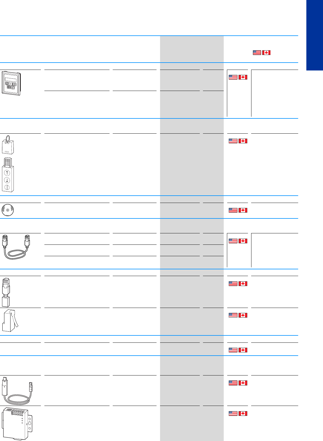
External keypad
with LED display
Front IP54
With approx. 3 m-long, plug-in
connection cable (RJ45, 8-pin)
DC1, DA1 DX-KEY-LED
169132
1off UL/CSA certification not
required
with OLED display
Front IP54
Multilingual
With approx. 3 m-long, plug-in
connection cable (RJ45, 8-pin)
DC1, DA1 DX-KEY-OLED
169133
Bluetooth communications stick
For transferring parameters to a computer with drivesConnect software via Bluetooth
With 2 function keys for uploading
and downloading parameters
with configuration memory
DC1, DA1 DX-COM-STICK
169134
1off UL/CSA certification not
required
License Keys
For enabling the drivesConnect
program's PLC function
DA1 DX-COM-SOFT
169136
1off UL/CSA certification not
required
Connection cable
Connection cable with RJ45 plugs, 8 pole
Length 0.5 m DC1, DA1 DX-CBL-RJ45-0M5
169137
1off UL/CSA certification not
required
Length 1 m DC1, DA1 DX-CBL-RJ45-1M0
169138
Length 3 m DC1, DA1 DX-CBL-RJ45-3M0
169139
Bus termination resistor
With 2 resistors, 120
RJ45 plug, 8-pin
for CANopen® and Modbus RTU
DX-SPL-RJ45-2SL-1PLT DX-CBL-TERM
169140
1off UL/CSA certification not
required
8 pole
RJ45
124
Connection to PIN 1 and PIN 2
für CANopen®
easyNet
easyNet
EASY-NT-R
256281
2off
Cable and splitter
RJ45, 8-pin, 2 sockets/1 plug DC1, DA1 DX-SPL-RJ45-2SL1PL
169142
1off UL/CSA certification not
required
Interface converter
For directly connecting the variable-frequency drive to a computer with drivesConnect
software
Interface converter USB/RS485 with
connection cable, RJ45, 8 pole
electrically isolated
DC1, DA1 DX-CBL-PC-1M5
171018
1off UL/CSA certification not
required
Interface converter USB/RS485 with
connection cable, RJ45, 8 pole
electrically isolated
1 × SUB-D plug, 9-pole
Terminal strip, 5-terminal
LED indicators
DC1, DA1 DX-COM-PCKIT
169135
1off UL/CSA certification not
required
PWR
USB
RxD
TxD
32 PowerXL™ variable frequency drives
Accessories
CA04020001Z-EN-INT www.eaton.eu
Description For use with Part no.
Article no.
Price
see price
list
Std. pack Information relevant for
export to North America
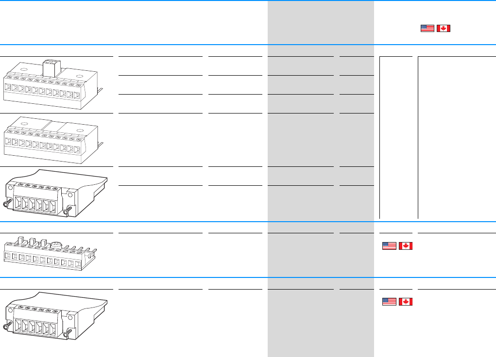
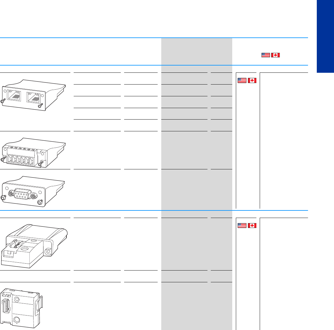
Expansion modules
110-V-input
(electrically isolated)
DC1 DXC-EXT-IO110
169032
1off
230-V-input
(electrically isolated)
DC1 DXC-EXT-IO230
169033
2 relay outputs
1 analog output
DC1 DXC-EXT-2RO1AO
169030
2 relay outputs DC1 DXC-EXT-2RO
169031
3 digital inputs
1 Relay output
DA1 DXA-EXT-3DI1RO
169036
3 relay outputs DA1 DXA-EXT-3RO
169121
Simulator
3 digital inputs
1 Relay output
1 Potentiometer
DC1 DXC-EXT-LOCSIM
169034
1off UL/CSA certification not
required
Encoder module
2-channel
max. 500 kHz
5 V TTL, A & B, /A & /B,
5 V DC, max. 200 mA
24 V HTL, A & B, /A & /B,
24 V DC, external power
supply required,
max. 30 V DC
DA1 DXA-EXT-ENCOD
169035
1off UL/CSA certification not
required
1 2 3 4 5 6 7 8 9 10 11
1 2 3 4 5 6 7 8 9 10 11
AB
1 2 3 4 5 6 7 8 9 10 11
AB
PowerXL™ variable frequency drives
Accessories
CA04020001Z-EN-INT www.eaton.eu
33
DC1, DA1
Fieldbus connection For use with Part no.
Article no.
Price
see price
list
Std. pack Information relevant for
export to North America
Fieldbus modules
2 x RJ45, 8 pole Ethernet IP DA1 DX-NET-ETHERNET-2
169122
1off UL/CSA certification not
required
Modbus-TCP DA1 DX-NET-MODBUSTCP-2
169126
EtherCAT DA1 DX-NET-ETHERCAT-2
169127
BACnet/IP DA1 DX-NET-BACNETIP-2
169128
PROFINET DA1 DX-NET-PROFINET-2
169125
Terminal strip, plug-in, 6-terminal DeviceNet DA1 DX-NET-DEVICENET
169123
SUB-D socket, 9-pole PROFIBUS-DP DA1 DX-NET-PROFIBUS
169124
SmartWire-DT Modules
with slot for SWD4-8SF2-5 SmartWire-DT DA1 (IP20) DX-NET-SWD1
169129
1off UL/CSA certification not
required
SmartWire-DT DC1/DA1
(IP55/IP66)
DX-NET-SWD2
169130
with slot for SWD4-8SF2-5 SmartWire-DT DC1 (IP20) DX-NET-SWD3
169131
IN OUT
AB
OP ST
PROFIBUS DP-V1
Ready
Ready
I
O
A
34 PowerXL™ variable frequency drives
Braking resistances
CA04020001Z-EN-INT www.eaton.eu
Braking resistances
Resistance
value
Continuous
braking
rating
Protection
type
For use
with
Part no.
Article no.
Price
see price
list
Std. pack Information relevant for export to
North America
RP
DB
kW
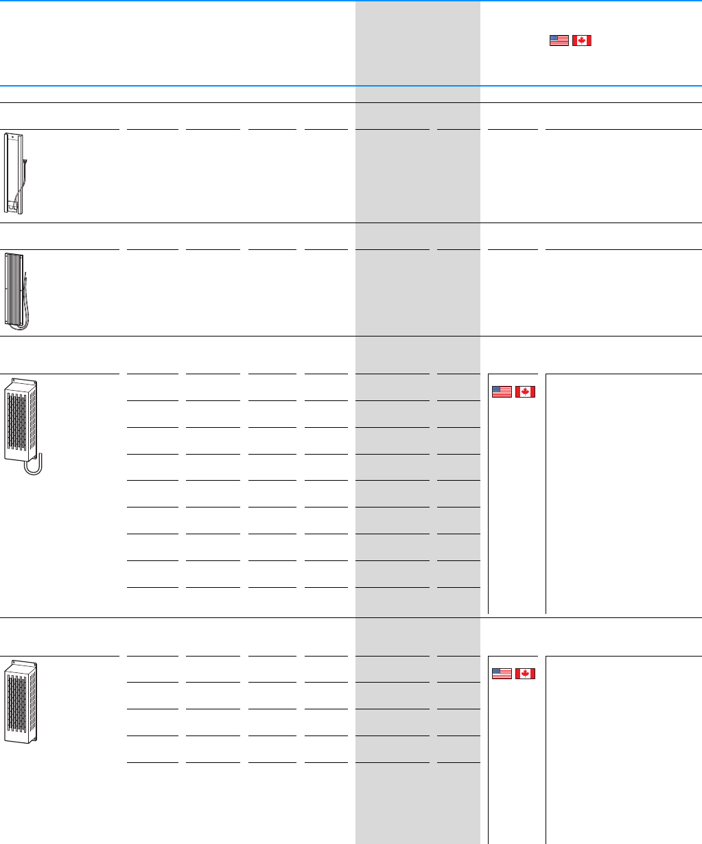
Braking resistances
Braking resistance in anodized aluminium enclosure
for direct installation in frequency inverter enclosure of frame sizes FS2 und FS3
100 0.2 IP54 DC1, DA1 DX-BR3-100
169150
1off
Braking resistance in aluminum housing
for direct installation in frequency inverter enclosure of frame sizes FS4 und FS5
33 0.5 IP54 DA1 DX-BR5-033
169151
1off
Braking resistance in aluminum housing
Installed in a housing designed to prevent accidental contact and featuring a
temperature monitoring switch and a 1-meter connection cable
75 1.4 IP20 DC1, DA1 DX-BR075-1K4
171917
1off Product Standards UL508; C22.2
UL File No. E300773
UL Category
Control No. NMTR2,
NMTR8
CSA File No. E300773
CSA Class No. 14-M05
North America
Certification UL listed,
certified by
UL for use in
Canada
Suitable for Branch
circuits
Max. Voltage Rating 600
Degree of Protection IEC: IP00
100 1.4 IP20 DC1, DA1 DX-BR100-1K4
171896
100 0.8 IP20 DC1, DA1 DX-BR100-0K8
171907
100 1.6 IP20 DC1, DA1 DX-BR100-1K6
171924
150 0.5 IP20 DC1, DA1 DX-BR150-0K5
171916
150 1.4 IP20 DC1, DA1 DX-BR150-1K4
171895
200 0.8 IP20 DC1, DA1 DX-BR200-0K8
171894
200 0.4 IP20 DC1, DA1 DX-BR200-0K4
171915
400 0.4 IP20 DC1, DA1 DX-BR400-0K4
171914
Braking resistance in aluminum housing
Installed in a housing designed to prevent accidental contact and featuring a
temperature monitoring switch and internal connecting terminals
35 1.1 IP20 DA1 DX-BR035-1K1
171927
1off Product Standards UL508; C22.2
UL File No. E300773
UL Category
Control No. NMTR2,
NMTR8
CSA File No. E300773
CSA Class No. 14-M05
North America
Certification UL listed,
certified by
UL for use in
Canada
Suitable for Branch
circuits
Max. Voltage Rating 600
Degree of Protection IEC: IP00
50 0.4 IP20 DC1, DA1 DX-BR050-0K4
171906
50 9.8 IP20 DC1, DA1 DX-BR050-0K8
171910
100 0.2 IP20 DC1, DA1 DX-BR100-0K2
171909
100 0.4 IP20 DC1, DA1 DX-BR100-0K4
171926
PowerXL™ variable frequency drives
Braking resistances
CA04020001Z-EN-INT www.eaton.eu
35
DC1, DA1
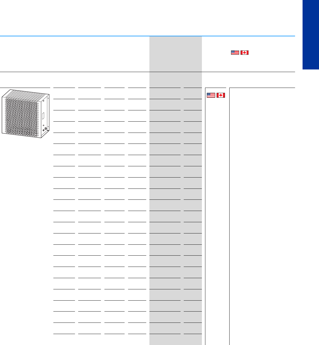
Braking resistance with steel wire mesh elements
Installed in a housing designed to prevent accidental contact and featuring a
temperature monitoring switch and internal connecting terminals
2 54.3 IP20 DA1 DX-BR002-54K3
171923
1off Product Standards UL508; C22.2
UL File No. E300773
UL Category
Control No. NMTR2,
NMTR8
CSA File No. E300773
CSA Class No. 14-M91
North America
Certification UL listed,
certified by
UL for use in
Canada
Suitable for Branch
circuits
Max. Voltage Rating 1000
Degree of Protection IEC: IP00
2102.4IP20DA1DX-BR002-102K4
171903
65.1IP20DA1DX-BR006-5K1
171913
69.2IP20DA1DX-BR006-9K2
171893
6 18.1 IP20 DA1 DX-BR006-18K1
171922
6 33.3 IP20 DA1 DX-BR006-33K3
171902
12 3.1 IP20 DA1 DX-BR012-3K1
171912
12 5.1 IP20 DA1 DX-BR012-5K1
171929
12 9.2 IP20 DA1 DX-BR012-9K2
171921
12 18.1 IP20 DA1 DX-BR012-18K1
171901
22 1.4 IP20 DA1 DX-BR022-1K4
171911
22 3.1 IP20 DA1 DX-BR022-3K1
171928
22 5.1 IP20 DA1 DX-BR022-5K1
171920
22 9.2 IP20 DA1 DX-BR022-9K2
171900
40 3.1 IP20 DA1 DX-BR040-3K1
171919
40 5.1 IP20 DA1 DX-BR040-5K1
171899
47 3.1 IP20 DC1, DA1 DX-BR047-3K1
171908
47 5.1 IP20 DC1, DA1 DX-BR047-5K1
171925
47 9.2 IP20 DC1, DA1 DX-BR047-9K2
171905
50 3.1 IP20 DC1, DA1 DX-BR050-3K1
171918
50 5.1 IP20 DC1, DA1 DX-BR050-5K1
171898
75 5.1 IP20 DC1, DA1 DX-BR075-5K1
171897
100 6.2 IP20 DC1, DA1 DX-BR100-6K2
171904
Resistance
value
Continuous
braking
rating
Protection
type
For use
with
Part no.
Article no.
Price
see price
list
Std. pack Information relevant for export to
North America
RP
DB
kW
36 PowerXL™ variable frequency drives
Mains chokes, motor chokes
CA04020001Z-EN-INT www.eaton.eu
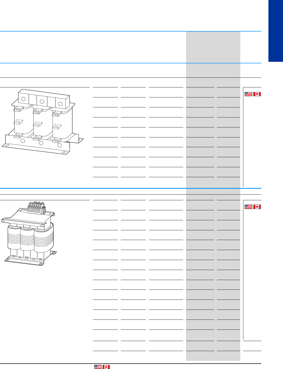
Mains chokes, motor chokes
Rated
operational
current
Inductance Maximum heat
dissipation
Part no.
Article no.
Price
see price list
Std. pack
IeLP
v
AmHW
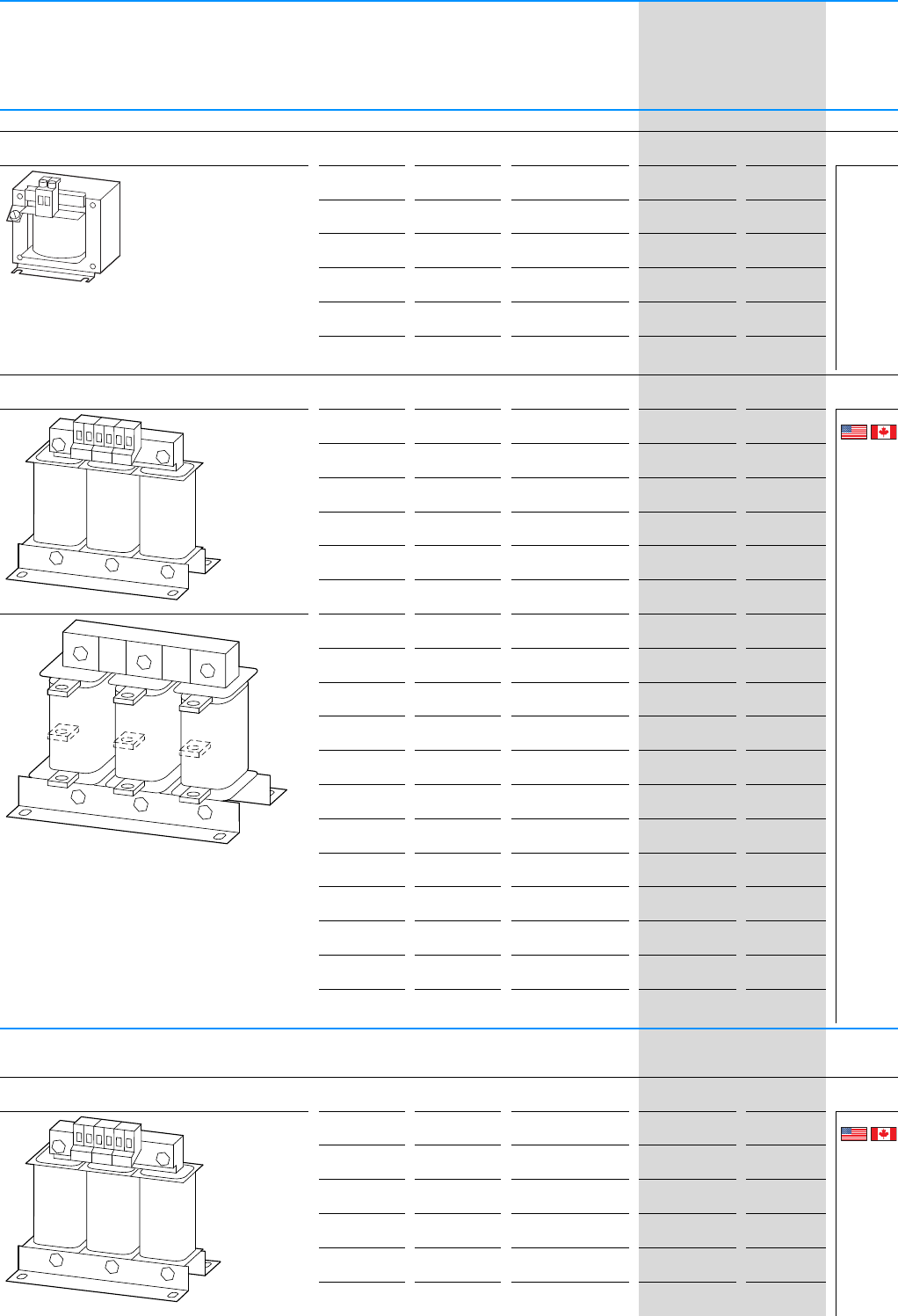
Mains chokes
Single-phase
max. permitted mains supply voltage V AC: 260 V + 0% (50/60 Hz)
5.8 5.05 9 DX-LN1-006
269490
1off
8.6 3.41 11 DX-LN1-009
269495
13 2.25 12 DX-LN1-013
269496
18 1.63 17 DX-LN1-018
269497
24 1.22 20 DX-LN1-024
269498
32 0.92 24 DX-LN1-032
169791
three-phase
max. permitted mains supply voltage V AC: 550 V + 0% (50/60 Hz)
3.9 7.51 17 DX-LN3-004
269500
1off
64.919 DX-LN3-006
269501
10 2.94 33 DX-LN3-010
269502
16 1.84 44 DX-LN3-016
269503
25 1.18 57 DX-LN3-025
269504
40 0.64 59 DX-LN3-040
269505
50 0.37 58 DX-LN3-050
269506
60 0.31 60 DX-LN3-060
269507
80 0.23 86 DX-LN3-080
269508
100 0.18 101 DX-LN3-100
269509
120 0.15 100 DX-LN3-120
269510
160 0.11 140 DX-LN3-160
269511
200 0.09 154 DX-LN3-200
269512
250 0.07 155 DX-LN3-250
269513
300 0.06 196 DX-LN3-300
269514
303 0.06 230 DX-LN3-303
169143
370 0.05 290 DX-LN3-370
169144
450 0.04 300 DX-LN3-450
169145
Motor chokes max. heat dissipation
(pulse frequency)
(12 kHz)
three-phase
max. permitted mains supply voltage V AC: 750 V + 0% (50/60 Hz)
5224 DX-LM3-005
269538
1off
84.154 DX-LM3-008
269539
11 3 71 DX-LM3-011
269541
16 1.5 78 DX-LM3-016
269542
35 1 116 DX-LM3-035
269543
50 0.6 168 DX-LM3-050
269544
PowerXL™ variable frequency drives
Motor chokes, sine filters
CA04020001Z-EN-INT www.eaton.eu
37
DC1, DA1
Motor chokes, sine filters
Rated
operational
current
Inductance Maximum heat
dissipation
Part no.
Article no.
Price
see price list
Std. pack
IeLP
v
AmHW
Motor chokes max. heat dissipation
(pulse frequency)
(12 kHz)
three-phase
max. permitted mains supply voltage V AC: 750 V + 0% (50/60 Hz)
63 0.5 193 DX-LM3-063
269545
1off
80 0.5 206 DX-LM3-080
269546
100 0.45 294 DX-LM3-100
269547
150 0.35 424 DX-LM3-150
269548
180 0.3 439 DX-LM3-180
269549
220 0.2 517 DX-LM3-220
269560
260 0.15 520 DX-LM3-260
269561
303 0.15 - DX-LM3-303
169146
370 0.12 - DX-LM3-370
169147
450 0.1 - DX-LM3-450
169148
Sine filter
three-phase
41150 DX-SIN3-004
271538
1off
10 5.1 100 DX-SIN3-010
271590
16.5 3.07 70 DX-SIN3-016
271591
23.5 2.5 125 DX-SIN3-023
271593
32 2 100 DX-SIN3-032
271594
37 1.7 100 DX-SIN3-037
271595
48 1.2 240 DX-SIN3-048
271597
61 1 280 DX-SIN3-061
271599
72 0.95 300 DX-SIN3-072
271600
90 0.8 290 DX-SIN3-090
271601
115 0 460 DX-SIN3-115
271602
150 0.5 530 DX-SIN3-150
271603
180 0.4 500 DX-SIN3-180
271604
250 0.35 550 DX-SIN3-250
271605
440 0.14 650 DX-SIN3-440
271606
1off
480 0.14 1550 DX-SIN3-480
169149
1off
Instructions Information relevant for export to North America
Product Standards UL 508C; CSA-C22.2 No. 14; IEC/EN61800-3; IEC/EN61800-5; CE marking
UL File No. E167225
UL Category Control No. XPTQ2, XPTQ8
CSA File No. UL report applies to both US and Canada
CSA Class No. 3211-06
North America Certification UL listed, certified by UL for use in Canada
Suitable for Branch circuits
Max. Voltage Rating 1~ 240 V AC IEC: TN-S UL/CSA: "Y" (Solidly Grounded Wey)
Degree of Protection IEC: IP00

38 PowerXL™ variable frequency drives
Radio interference suppression filters
CA04020001Z-EN-INT www.eaton.eu
Radio interference suppression filters
Input current For use with Part no.
Article no.
Price
see price list
Std. pack
ILN
T
Radio interference suppression filters
Single-phase
Mains voltage (50/60Hz) ULN [V] max. 240 + 10%
Base-mounted filter
8DC1-12
DA1-12…
DX-EMC12-008
172273
1off
12 DX-EMC12-012
172274
16 DX-EMC12-016
172275
20 DX-EMC12-020
172276
30 DX-EMC12-030
172277
three-phase
Mains voltage (50/60Hz) ULN [V] max. 480 + 10%
Base-mounted filter
8 DC1-32…
DC1-34…
DA1-32…
DA1-34…
DX-EMC34-008
172278
1off
12 DX-EMC34-012
172279
16 DX-EMC34-016
172280
30 DX-EMC34-030
172281
Mounting to the side, next to the variable frequency drive
42 DA1-32…
DA1-34…
DX-EMC34-042
172282
55 DX-EMC34-055
172283
75 DX-EMC34-075
172284
100 DX-EMC34-100
172285
130 DX-EMC34-130
172286
180 DX-EMC34-180
172287
250 DX-EMC34-250
172288
400 DX-EMC34-400
172289
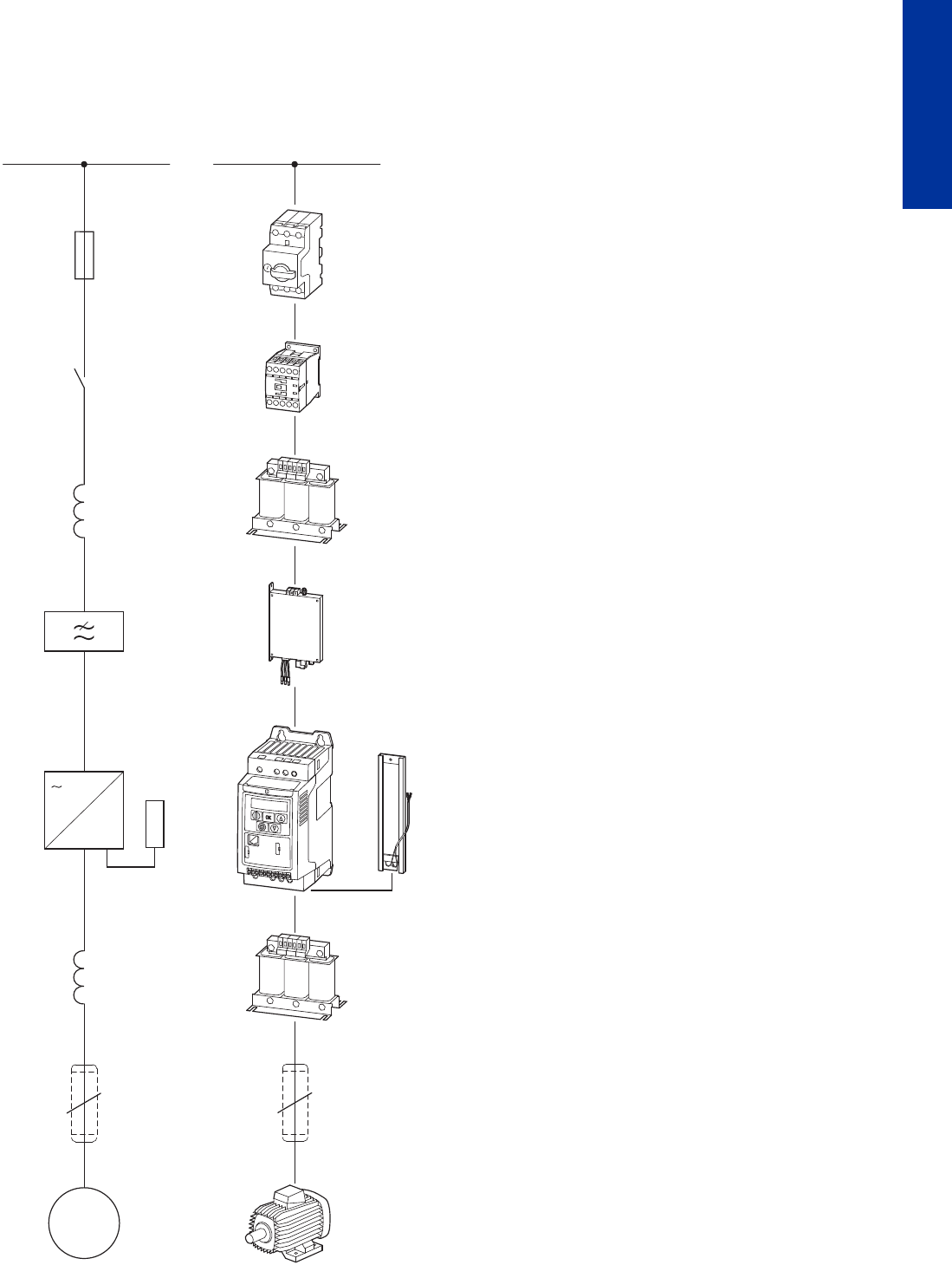
CA04020001Z-EN-INT www.eaton.eu
PowerXL™ variable frequency drives
Assigned switching and protective elements
39
DC1, DA1
Assigned switching and protective elements
Engineering
AC supply system: Variable-frequency drives can be connected without restriction
to AC supply systems with a grounded star point (TN/TT grounding systems).
Directly connecting them to and running them on unbalanced or B phase-grounded
systems (e.g., USA) is not permissible.
Fuses (circuit-breakers) allow the protection of lines and electrical devices.
For the protection of persons, AC/DC-sensitive residual current circuit-breakers
(RCD Type B) are required in addition.
Contactors are used to switch the mains voltage on and off.
Mains choke damp harmonic distortion (THD) and current peaks and limit inrush
currents (the DC link capacitors' charging current). In addition, they protect the
mains rectifier from voltage peaks coming from the mains.
Radio interference suppression filter attenuate high-frequency electromagnetic
emissions from devices. They ensure that the EMC limit values for conducted
interference specified in the applicable product standards are complied with
(variable-frequency drives).
Note: External radio interference suppression filters (optional) make it possible to
use longer motor cables and have low leakage currents. Normally, they should only
be used with variable-frequency drives that do not feature an internal radio
interference suppression filter.
Exception: directly assigned variable-frequency drives with internal filters
(calibrated combination)
variable frequency drive allow the continuously variable speed control of three-
phase motors. To do this, the variable-frequency drive converts the voltage of the
AC supply system with a constant voltage and a constant frequency to a new AC
voltage with a variable amplitude and a variable frequency.
On brake resistor converts the variable frequency drive's regenerative braking
energy into heat. The variable frequency drive must be equipped with a brake
chopper, which connects the braking resistance parallel to the internal DC link.
Motor choke
• Compensate the capacitive capacitive currents,
• Reduce current ripple and the motor’s current change noise,
• Attenuate the retroaction on parallel connection of several motors.
sine filter
• Smoothen the output voltage sinusoidally,
• reduce motor noise through du/dt reduction, and thereby increase the motor
insulation’s lifespan,
• Reduce the leakage currents to allow better motor performance at improved EMC
values.
Screened motor cables attenuate radiated and conducted high-frequency
emissions within the limits defined in the applicable product standard (EMC). They
must be connected to the earth potential on both sides across a large area (PES).
Three-phase asynchronous motor (standard motor) converts electric power
(P ~ U × I) into mechanical power (P ~ M × n).
Equipment code
F = fuses and circuit-breakers
Q = controlled switching within energy flow (contactors, circuit-breakers)
R = limitation (reactors, resistors)
K = radio interference suppression filters
T = variable-frequency drives
M = motors
M
3~
3~
F
Q
R
R
K
T
M
3
R
3
L1/L L2/N L3
UVW
123456789
10
11
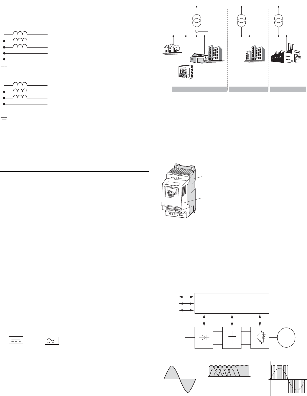
CA04020001Z-EN-INT www.eaton.eu
40 PowerXL™ variable frequency drives
General information on Engineering
General information on Engineering
Electrical mains connection
Frequency inverters can be connected
to and operated on star point-earthed
AC supply systems (as per IEC 60364)
without restrictions.
Connecting them to and operating
them on asymmetrically earthed
networks, such as phase-earthed
delta networks (grounded delta, USA)
or non-earthed or high-resistance
earthed (> 30 ) IT networks is
permitted with limitations. In these
networks, only frequency inverters
without internal radio interference
suppression filters (EMC) may be used.
In the case of devices with an
integrated radio interference
suppression filter, the filter’s
protective earth connection must be
disconnected.
The standardized rated operating
voltages of the utility companies fulfil
the following conditions at the point of
transfer to the consumer:
• maximum deviation from the rated
voltage (ULN): ±10 %
• Maximum deviation in the voltage
symmetry: ±3 %
• Maximum deviation from the rated
frequency: ±4 %
A further voltage drop of up to 4% in
the consumer networks is permissible
relative to the lower voltage value
(ULN -10%) of the mains voltage.
In ring-operated mesh networks (such
as in the EU) the standardized
consumer voltages (230/400/690 V) are
identical to the utility company’s
supply voltages. In star networks (for
example in North America/USA), the
stated consumer voltages take the
voltage drop from the utility company’s
infeed point to the last consumer into
account.
Safety and switching
For frequency inverters, the
components placed on the mains-side
are assigned as per the input-side
rated operational current ILN and the
AC-1 utilization category.
Fuses, circuit-breakers and conductor
cross-sections must meet the national
and regional requirements and the
required approvals at the point of
operation.
For fire prevention and the protection
of persons and domestic animals from
excessive contact voltages residual
current devices (RCD) must be used.
Only AC/DC sensitive residual current
devices (RCD, type B) may be used in
connection with a frequency inverter.
Marking on residual current devices
for AC/DC sensitive RCDs, type B:
Earth leakage currents will be
produced when using frequency-
controlled drives due to the nature of
the system. The main reasons for this
consist of external capacitances
between the phases of the motor
cable, the motor cable's screening,
Y capacitors in the frequency inverter,
and radio interference suppression
filters, as well as earthing measures at
the motor's site of operation. These
leakage currents can exceed 3.5 mA
and require improved PDS earthing as
per EN 50178 (earth conductor cross-
section 10 mm2).
EMC compliance
Frequency inverters work with fast
electronic switches (IGBT) in the
inverter. This can cause radio
interference in a drive system, which,
in turn, can adversely affect nearby
electronic equipment. To provide
protection from this high-frequency
interference, these should be spatially
separated and screened from
frequency-controlled drives.
In Europe, adherence to the EMC
Directive is mandatory. The EMC
product standard for power drive
systems (PDS) is IEC/EN 61800-3. This
standard covers the complete drive
system, from mains infeed to the
motor.
Both versions of DC1 and DA1 series
frequency inverters (with internal/
external radio interference
suppression filter) meet the
requirements of the EMC product
standard for residential areas (first
environment) and therefore the higher
limits for industrial environment
(second environment) as well.
L2
N
L1
L3
PE
L2
PEN
L1
L3
Table: North American voltage level
Supply voltage ULN
of the EVU
Motor voltage according
to UL 508 C
Consumer voltage, rated
value for the motors
120 V 110 - 120 V 115 V
240 V 220 - 240 V 230 V
480 V 440 - 480 V 460 V
600 V 550 - 600 V 575V
Frequency inverters
A frequency inverter is an electronic
apparatus used for the variable-speed
control of three-phase motors. It is
intended for installation in a machine
or for assembly with other
components to a machine or plant. The
main components of a modern
compact frequency inverter are a
power section and a control
section .
The functional control of the frequency
inverter and the output values in the
power section (such as frequency,
voltage and current) can be adjusted
through:
• Control terminals (I/O) with analog
and digital (binary) inputs,
• A keypad with function keys and
display units,
• Serial interfaces (BUS) with RS485
(Modbus RTU) and optional
fieldbus connections (CANopen,
PROFIBUS-DP etc.) and an optional
PC connection.
Internal open and closed-loop control
circuits monitor all variable values in
the frequency inverter and
automatically switch the process off if
a value reaches a dangerous level.
The power section of a static compact
frequency generally consists of three
subgroups:
• Rectifier (A),
• Internal DC link (B),
• Inverter module (C).
1. Environment
Public medium-voltage system
PCC
Category C1
Category C2
Category C1 / C2 Category C1 / C2
Category C3 / C4
Category C3 / C4
1.or 2. environment 2. Environment
Public
low-voltage system
Private
mains
Industrial
mains
Power section with:
A = Rectifier
B = Internal DC link
C = inverter (IGBT)
Control section with:
I/O = Analog and binary
inputs and outputs
KEYPAD = Operating unit with
display unit
BUS = Serial ports/interfaces
(RS485, field bus, PC interface)
L1/L L2/N L3
DC-
U
DC+ BR
1 2 3 4 5 6 7 8 9 10 11 12 13
14 15 16 17 18
COM
VW
①
②
ULN = phase voltage
fromsupplying AC
mains
UDC = DC link voltage
UDC = 1.41 x ULN
Output voltage =
switched DC link
voltage with sinusoidal
pulse width modula-
tion (PWM)
Block diagram with main components of a frequency inverter
CPU
ABC
BUS
M
3 ∼
KEYPAD
I/O
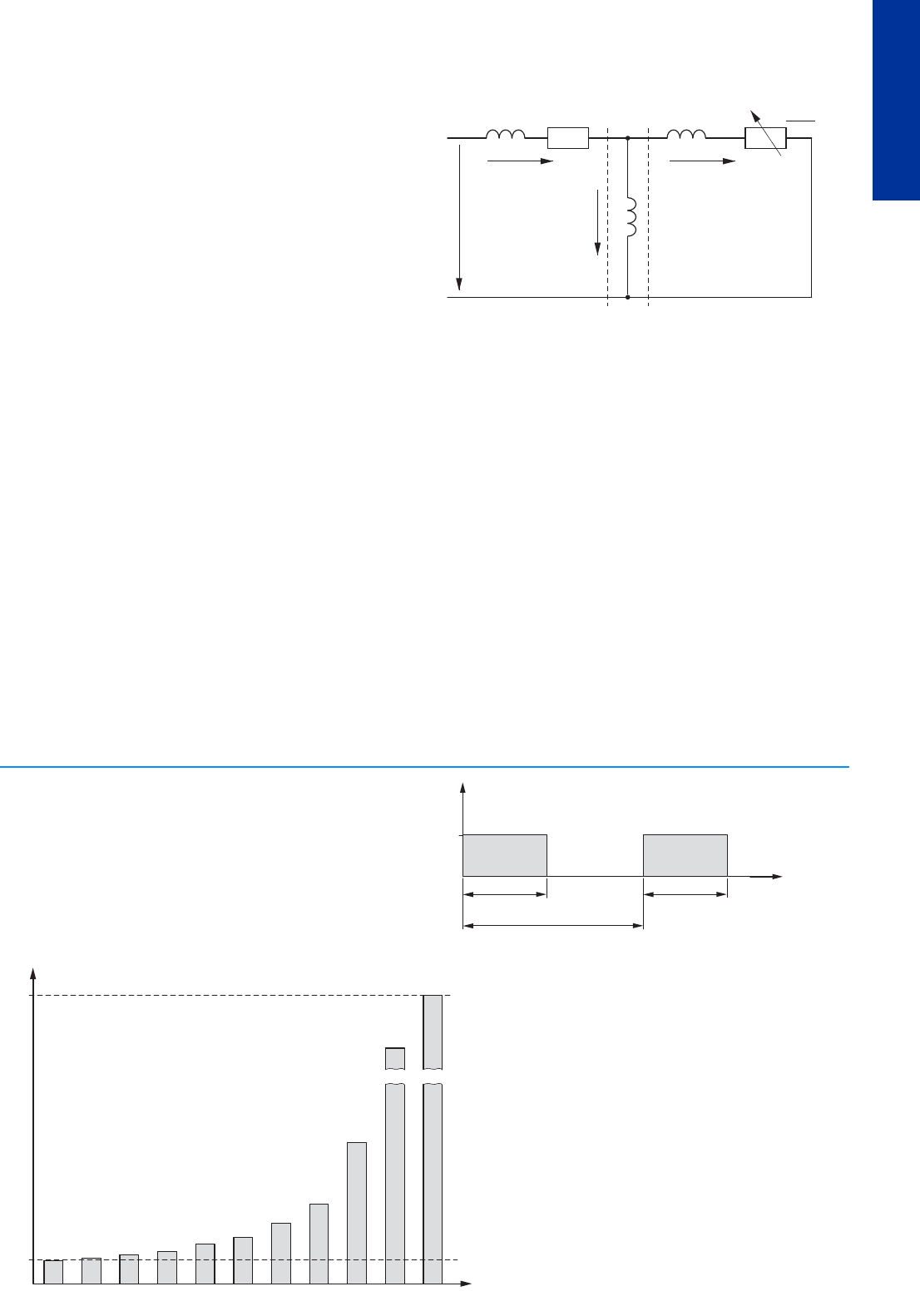
CA04020001Z-EN-INT www.eaton.eu
PowerXL™ variable frequency drives
General information on Engineering
41
DC1, DA1
General information on Engineering
Control methods
The IGBTs in the variable frequency
series' inverter are controlled with
sinusoidal pulse-width modulation
(PWM). In real-life applications, the
industry draws a distinction between
the following control methods:
• Voltage frequency control
(U/f control),
• V/Hz control with slip compensation
• Sensorless vector control
(speed control)
• Vector control (closed-loop)
The Voltage frequency control is the
best known and most commonly used
method. A simple characteristic curve
(linear or quadratic) defines the
motor’s rotating field frequency and
the corresponding three-phase line-
to-line motor voltage is selected such
that the motor is neither over nor
under-magnetized.
Main applications of U/f control:
• pump and fan drives,
• horizontal conveying and
transportation systems,
• multiple motor drives (parallel
operation of several motors at the
variable frequency drive’s output).
Bei der V/Hz control with slip
compensation can compensate for the
load-dependent speed change in
individual drives (sensorless).
Bei der In sensorless vector control
the magnetic fields of the stator and
rotor windings are aligned so as to
oppose each other. With
asynchronous motors the magnetic
flux in the rotor must be mapped in an
electronic model of the motor. This
requires the physical parameters on
the motor’s rating plate to be entered.
In vector operation the
frequencyinverter can control only
one motor. A parallel operation of
several motors is not possible here.
The exact calculation of the phase
voltages at the variable frequency
drive’s output, however, improves the
motor’s operational behavior. The
motor also heats up less in the lower
speed range. The field-oriented vector
control results in a significant
improvement in the drive dynamics as
well as optimizing performance; it also
increases the range of possible
applications.
The main applications of
sensorlessvector control are:
• Material machining and processing
equipment
• Condensors (compressor),
• Heavy starting duty (extruder,
agitators, mixer),
• Horizontal conveying equipment
(cranes, elevators).
Bei der Vector control uses the
variable frequency drive's output
current as a controlled variable. This
makes it possible to perfectly adjust
the three-phase motor in line with the
corresponding torque boost. The
motor speed can be controlled in
connection with an rpm sensor
(tachometer, pulse generator)
(closed loop).
Motor model
Regardless of the control method
used, a variable frequency drive uses
the measured voltage and current
values on the stator winding (u1, i1)
to calculate the required manipulated
variable for flux-generating
component i and torque-generating
component in the rotor iw. The motor's
load dependent slip is represented as
resistor R‘2/s. During no-load
operation, this value approaches
infinity (iw 0). On the other hand, the
value approaches zero as the load
increases. The current in the rotor
grows at this point.
Explanation:
EMC = Electromagnetic
compatibility
EVU = Utility company
IGBT = Insulated-gate bipolar
transistor
PDS = Magnet system
RCD = Residual current device
Stator winding
Air gap
Transformed rotor winding
Simplified equivalent circuit diagram for a three-phase motor
R1
①③②
X'2
X1
i1iw
u1Xh
iμ
R'2
s
Technical information concerning braking resistances:
The braking resistors' specified PDB power dissipation applies to
continuous operation.
In short-time operation these values can be increased by multiplying them with the
type-specific power factor using the following formula:
Pmax (PDB × 100 %) ÷ ED [%]
Pmax = maximum pulse rating
PDB = continuous rating at a duty factor of 100 %
ED = duty factor
tc = Cycle time (max. 120 seconds)
The duty factor is stated as a percentage (%) and is calculated with the formula:
ED [%] = (ED × 100 %) ÷ tc
P
DB
t [s]
ED
t
C
(F 120 s)
PDB
ED
Pmax
1
2
6
1.1 1.25 1.4 1.7
2.6
3.4
10
20
100 90 80 70 60 50 40 30 20 10 5
ED [%]
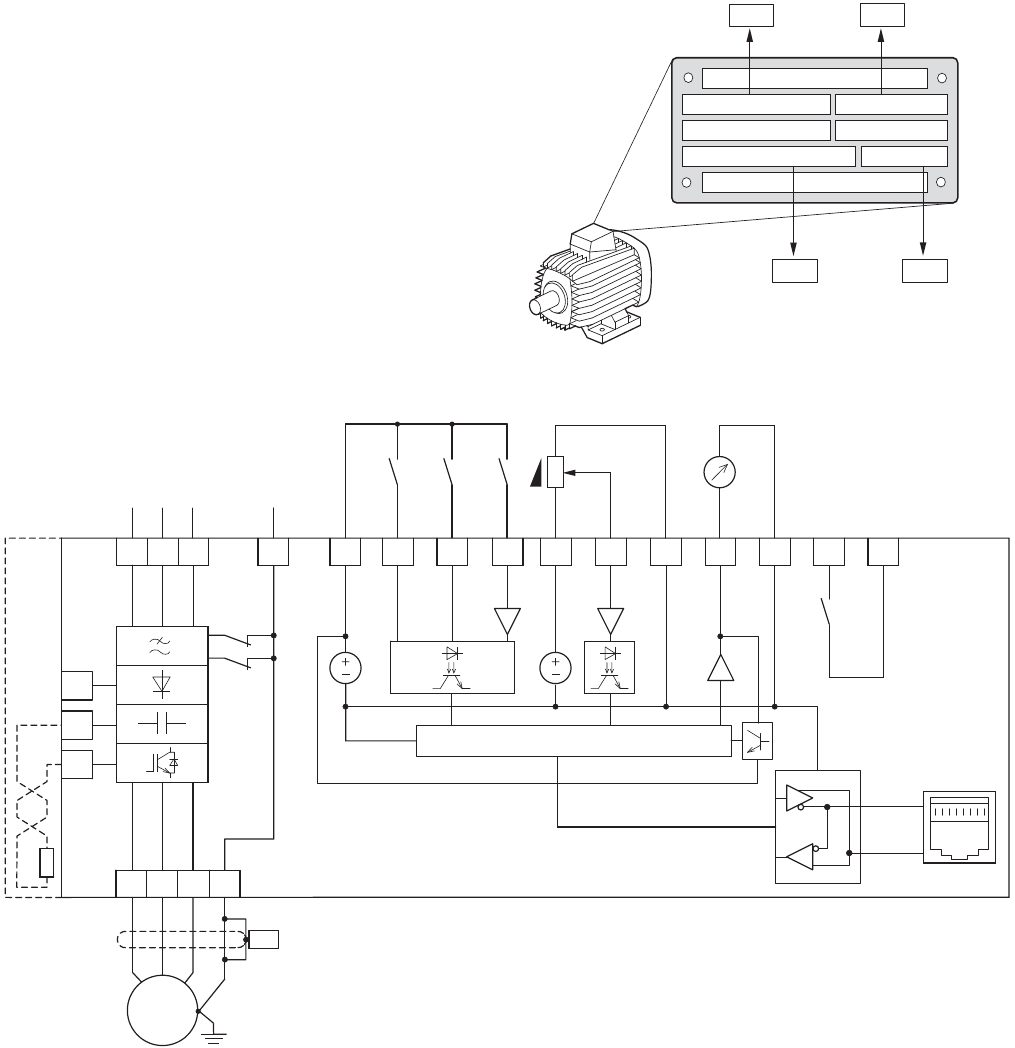
CA04020001Z-EN-INT www.eaton.eu
42 PowerXL™ variable frequency drives
Connection example for DC1
Connection example for DC1
Connecting example for a
0.75 kW motor with
the rating plate illustrated here.
The variable frequency drives are
configured by default in such a way
that they can be operated immediately
with V/Hz control when connected to
the assigned motor rating without
having to configure any additional
parameters.
To ensure ideal operational behavior
(e.g., slip compensation, vector
control, etc.), the data on the motor’s
rating plate should be entered into the
variable frequency drive (electric
motor map).
The following example shows the
necessary parameter settings for a
variable frequency drive (a DC1 in this
example)
1410 min
230/400 V 3.2/1.9 A
50 Hz
-1
0.75 kW cos ϕ 0.79
P-07 P-08
P-10 P-09
and connection examples for single-
phase and three-phase mains voltages:
Block diagram for DC1-32... and DC1-34... with internal radio interference suppression filter
Only sizes FS2 and FS3 have connection terminals DC+ and BR- for an external braking resistance (optional).
DC+
BR
DC-
3 AC 230/400/460 V
WVU
M
3 ~
2
DI1 FWD
24 V
3
DI2 REV
4
DI3
AI2
FF1
5
+10 V Out
< 10 mA
10 V
6
AI1
DI4
f-Soll
7
0 V
1
+24 V Out
< 100 mA
L1/L
L3
EMC
8
0...+10 V
< 20 mA AO
+24 V DO
f-Out
+
9
0 V
PIN 8
(PIN2)
PIN 7
(PIN 1)
10
L2/N
VAR
11
RUN
6 A, 250 VAC
5 A, 30 VDC
RS485
CPU
0...+10 V
3 AC 230 V
3 AC 400/480 V
50/60 Hz
PES
X1
①
①
FS2, FS3
The control signal terminals are
factory set as follows:
1: 24 V: +24 V control voltage,
max. 100 mA
2: DI1: FWD = Clockwise rotating
field enable (Forward)
3: DI2: REV = Anticlockwise
rotating field enable (Reverse)
4: DI3: FF1 = Fixed frequency 1
or AI2
5: 10 V: +10 V reference voltage,
max. 10 mA
6: AI1: f-setpoint = Frequency
setpoint value (0 - +10 V)
7: 0 V, reference potential
8: AO: f-Out = Output frequency
to motor (0 - +10 V)
9: 0 V, reference potential
10/11: Relay: RUN = Operating signal
(N/O)
DI: Digital input = +24 VDC digital
input
AI: Analog input = 0 - 10 V,
0/4 - 20 mA analog input
DO: Digital output = +24 VDC,
max. 20 mA digital output
AO: Analog output = 0 - +10 V,
max. 20 mA analog output
Parameters are used to define the
function and mode of operation for
the digital and analog inputs/outputs.
These parameters are described in
manual MN04020003Z.
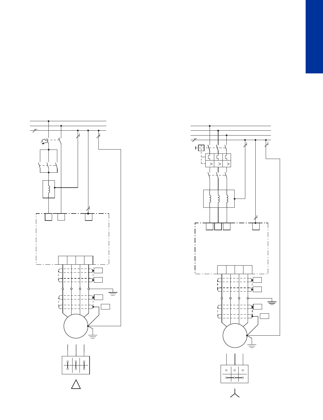
CA04020001Z-EN-INT www.eaton.eu
PowerXL™ variable frequency drives
Connection example for DC1
43
DC1, DA1
Connection example for DC1
Connection example for a 0.75 kW motor
Motor: P = 0.75 kW
Mains: 3/N/PE 400 V 50/60 Hz
Connection examples meeting EMC requirements: Power section (see figure below)
Variant A:
Motor in delta configuration
DC1… frequency inverter with single-phase mains supply (230 V)
Optional connection option for single-phase connections
PE
L
N
PE
2
1
R1
①
PE
1 ∼ 230 V, 50/60 Hz
L1
T1
Q1
UVWPE
PES
PES
PES
PES
M
M1
X1
3 ~
F1FAZ-B10/1N
DX-LN1-009
DC1-124D3…
(4.3 A)
230 V
3.2 A
0.75 kW
DILM7
(+DILM12-XP1)
U1 V1 W1
W2 U2 V2
L2/N
The previously indicated 0.75 kW motor can be connected in a delta configuration
for a single-phase 230-V supply system (version A) or in a star configuration for a
400-V supply system (version B).
The frequency inverter and the type-specific accessories are selected
for 1 AC 230 V (DC1-124D3...) or for 3 AC 400 V (MMX34AA2D4) depending on the
mains voltage selected.
Variant B:
Motor in star configuration
DC1… frequency inverter with three-phase mains supply (400 V)
3 ∼ 400 V, 50/60 Hz
W2
L1
L2/N
L3 PE
L1
L2
L3
PE
Q11
Q1
V2U2
W1V1U1
R1
PE
III
U1 V1 W1
W2 U2 V2
T1 UVWPE
PES
PES
PES
PES
M
M1
X1
3 ~
PKM0-6,3
DX-LN3-004
DC1-342D2…
(2.2 A)
400 V
1.9 A
0.75 kW
DILEM-10
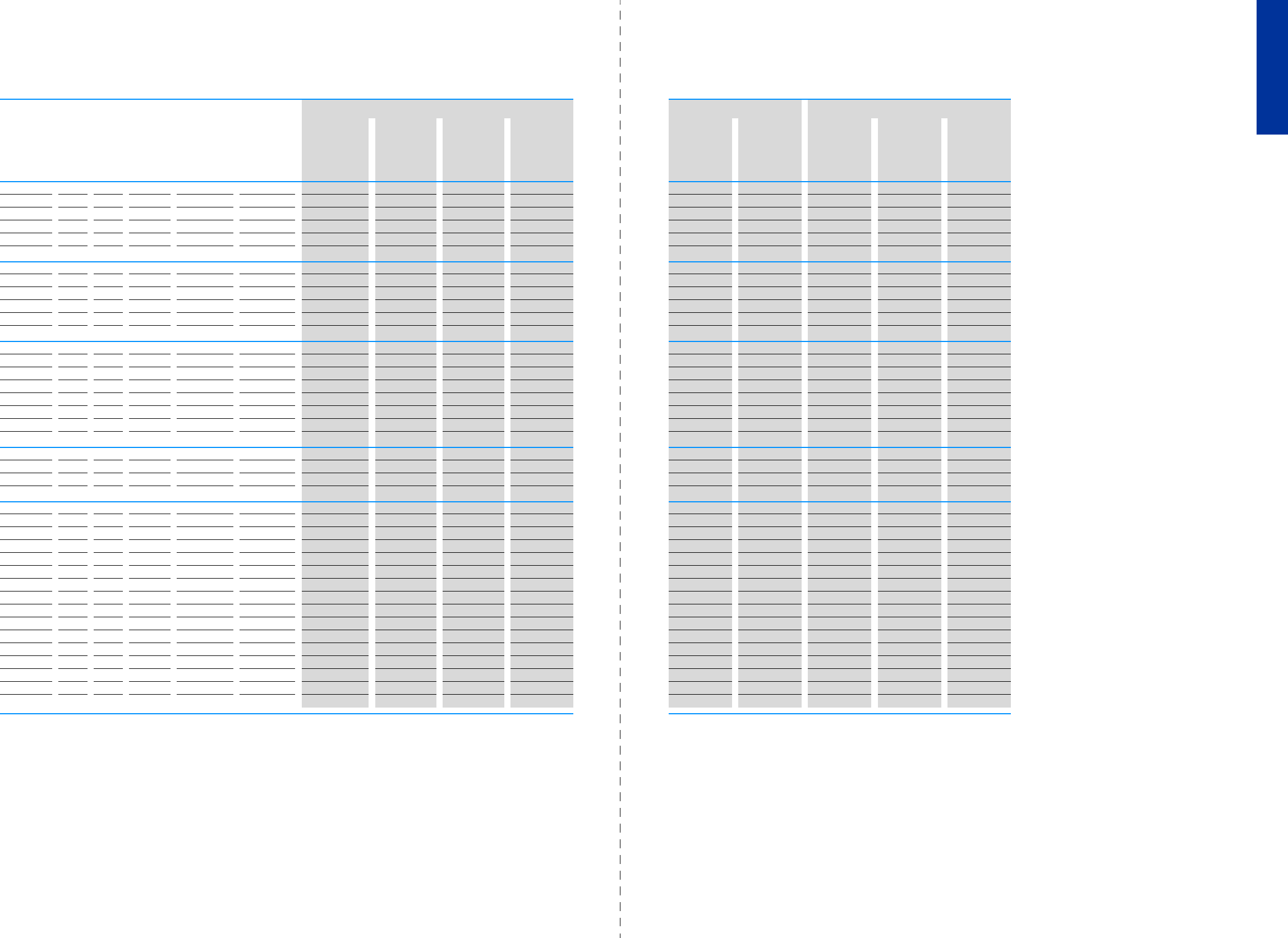
44 PowerXL™ variable frequency drives
Assigned switching and protective elements
CA04020001Z-EN-INT www.eaton.eu CA04020001Z-EN-INT www.eaton.eu
PowerXL™ variable frequency drives
Assigned switching and protective elements
DC1, DA1
Assigned switching and protective elements
Engineering
Part no. Motor Frequency inverters Power Wiring Motor connection Braking resistances for duty factors (DF) as a %3)
Assigned motor
rating 1)
Rated
motor
current
Rated
operational
current2)
Input current Protection device Protection
device
Contactor Mains choke Motor choke Sine filter 10% 20% 40%
PPI
eIeILN
kW HP A A T
Ue230 V AC, 1-phase/U2230 V AC, 3-phase
DC1-122D3 0.37 0.5 2 2.3 5 FAZ-B10/1N -DILM7 DX-LN1-006 DX-LM3-005 DX-SIN3-004 - - -
DC1-124D3 0.75 1 3.2 4.3 8.5 FAZ-B10/1N -DILM7 DX-LN1-013 DX-LM3-005 DX-SIN3-010 - - -
DC1-127D0 1.5 2 6.3 7 13.9 FAZ-B16/1N -DILM7 DX-LN1-018 DX-LM3-008 DX-SIN3-010 DX-BR050-0K4 DX-BR050-0K8 DX-BR047-3K1
DC1-12011 2.2 3 8.7 10.5 19.5 FAZ-B25/1N -DILM7 DX-LN1-024 DX-LM3-011 DX-SIN3-016 DX-BR050-0K4 DX-BR050-0K8 DX-BR047-3K1
DC1-12015 4 5 14.8 15 30.5 FAZ-B40/1N -DILM7 DX-LN1-032 DX-LM3-016 DX-SIN3-016 DX-BR050-0K4 DX-BR050-0K8 DX-BR047-3K1
Ue230 V AC, 3-phase/U2230 V AC, 3-phase
DC1-322D3 0.37 0.5 2 2.3 3 FAZ-B6/3 PKM0-6,3 DILM7 DX-LN3-004 DX-LM3-005 DX-SIN3-004 - - -
DC1-324D3 0.75 1 3.2 4.3 4.5 FAZ-B6/3 PKM0-6,3 DILM7 DX-LN3-006 DX-LM3-005 DX-SIN3-010 - - -
DC1-327D0 1.5 2 6.3 7 7.3 FAZ-B10/3 PKM0-10 DILM7 DX-LN3-010 DX-LM3-008 DX-SIN3-010 DX-BR050-0K4 DX-BR050-0K8 DX-BR047-3K1
DC1-32011 2.2 3 8.7 10.5 11 FAZ-B16/3 PKM0-16 DILM7 DX-LN3-016 DX-LM3-011 DX-SIN3-016 DX-BR050-0K4 DX-BR050-0K8 DX-BR047-3K1
DC1-32018 4 5 14.8 18 18.8 FAZ-B20/3 PKM0-20 DILM7 DX-LN3-025 DX-LM3-035 DX-SIN3-023 DX-BR050-0K4 DX-BR050-0K8 DX-BR047-3K1
Ue400 V AC, 3-phase/U2400 V AC, 3-phase
DC1-342D2 0.75 1 1.9 2.2 2.4 FAZ-B6/3 PKM0-6,3 DILM7 DX-LN3-004 DX-LM3-005 DX-SIN3-004 - - -
DC1-344D1 1.5 2 3.6 4.1 4.3 FAZ-B6/3 PKM0-6,3 DILM7 DX-LN3-006 DX-LM3-005 DX-SIN3-010 DX-BR100-0K8 DX-BR100-1K6 DX-BR100-6K2
DC1-345D8 2.2 3 5 5.8 6.1 FAZ-B10/3 PKM0-10 DILM7 DX-LN3-010 DX-LM3-008 DX-SIN3-010 DX-BR100-0K8 DX-BR100-1K6 DX-BR100-6K2
DC1-349D5 4 5 8.5 9.5 9.8 FAZ-B16/3 PKM0-16 DILM7 DX-LN3-010 DX-LM3-011 DX-SIN3-010 DX-BR100-0K8 DX-BR100-1K6 DX-BR100-6K2
DC1-34014 5.5 7.5 11.3 14 14.6 FAZ-B20/3 PKM0-20 DILM7 DX-LN3-016 DX-LM3-016 DX-SIN3-016 DX-BR047-3K1 DX-BR047-5K1 DX-BR047-9K2
DC1-34018 7.5 10 15.2 18 18.1 FAZ-B25/3 PKM0-25 DILM7 DX-LN3-025 DX-LM3-035 DX-SIN3-023 DX-BR047-3K1 DX-BR047-5K1 DX-BR047-9K2
DC1-34024 11 15 21.7 24 24.7 FAZ-B32/3 PKM0-32 DILM17 DX-LN3-025 DX-LM3-035 DX-SIN3-023 DX-BR047-3K1 DX-BR047-5K1 DX-BR047-9K2
Ue230 V AC, 1-phase/U2230 V AC, 3-phase
DA1-124D3 0.75 1 3.2 4.3 8.5 FAZ-B10/1N -DILM7 DX-LN1-013 DX-LM3-005 DX-SIN3-010 DX-BR100-0K2 DX-BR100-0K4 -
DA1-127D0 1.5 2 6.3 7 13.9 FAZ-B16/1N -DILM7 DX-LN1-018 DX-LM3-008 DX-SIN3-010 DX-BR050-0K4 DX-BR050-0K8 -
DA1-12011 2.2 3 8.7 10.5 19.5 FAZ-B25/1N -DILM7 DX-LN1-024 DX-LM3-011 DX-SIN3-016 DX-BR050-0K8 DX-BR035-1K1 -
Ue230 V AC, 3-phase/U2230 V AC, 3-phase
DA1-324D3 0.75 1 3.2 4.3 4.5 FAZ-B6/3 PKM0-6,3 DILM7 DX-LN3-006 DX-LM3-005 DX-SIN3-010 DX-BR100-0K2 DX-BR100-0K4 -
DA1-327D0 1.5 2 6.3 7 7.3 FAZ-B10/3 PKM0-10 DILM7 DX-LN3-010 DX-LM3-008 DX-SIN3-010 DX-BR050-0K4 DX-BR050-0K8 -
DA1-32011 2.2 3 8.7 10.5 11 FAZ-B16/3 PKM0-16 DILM7 DX-LN3-016 DX-LM3-011 DX-SIN3-016 DX-BR050-0K8 DX-BR035-1K1 -
DA1-32018 4 5 14.8 18 18.8 FAZ-B20/3 PKM0-20 DILM7 DX-LN3-025 DX-LM3-035 DX-SIN3-023 DX-BR022-1K4 DX-BR022-3K1 -
DA1-32024 5.5 7.5 19.6 24 24.8 FAZ-B32/3 PKM0-32 DILM17 DX-LN3-025 DX-LM3-035 DX-SIN3-032 DX-BR022-1K4 DX-BR022-3K1 -
DA1-32039 7.5 10 26.4 39 40 FAZ-B50/3 -DILM25 DX-LN3-040 DX-LM3-050 DX-SIN3-048 DX-BR022-1K4 DX-BR022-3K1 -
DA1-32046 11 15 38 46 47.1 FAZ-B63/3 -DILM40 DX-LN3-050 DX-LM3-050 DX-SIN3-048 DX-BR022-1K4 DX-BR022-3K1 -
DA1-32061 15 20 51 61 62.4 NZMC1-S80 -DILM50 DX-LN3-080 DX-LM3-063 DX-SIN3-061 DX-BR012-3K1 DX-BR012-5K1 -
DA1-32072 18.5 25 63 72 74.1 NZMC1-S80 -DILM65 DX-LN3-080 DX-LM3-080 DX-SIN3-072 DX-BR012-3K1 DX-BR012-5K1 -
DA1-32090 22 30 71 90 92.3 NZMC2-S100 -DILM80 DX-LN3-100 DX-LM3-100 DX-SIN3-090 DX-BR006-5K1 DX-BR006-9K2 -
DA1-32110 30 40 96 110 112.7 NZMC2-S125 -DILM95 DX-LN3-120 DX-LM3-150 DX-SIN3-115 DX-BR006-5K1 DX-BR006-9K2 -
DA1-32150 45 50 141 150 153.5 NZMC2-S160 -DILM150 DX-LN3-160 DX-LM3-150 DX-SIN3-150 DX-BR006-5K1 DX-BR006-9K2 -
DA1-32180 55 60 173 180 183.8 NZMC2-S200 -DILM170 DX-LN3-200 DX-LM3-180 DX-SIN3-180 DX-BR006-5K1 DX-BR006-9K2 -
DA1-32202 55 75 173 202 206.2 NZMC3-S250 -DILM185A DX-LN3-250 DX-LM3-220 DX-SIN3-250 DX-BR006-5K1 DX-BR006-9K2 -
DA1-32248 75 100 233 248 252.8 NZMC3-S320 -DILM185A DX-LN3-300 DX-LM3-260 DX-SIN3-250 DX-BR006-5K1 DX-BR006-9K2 -
1) Assigned motor rating for normal internally and externally ventilated four-pole, three-phase
asynchronous motors with 1500 rpm (at 50 Hz) or 1800 rpm (at 60 Hz)
2) With a switching frequency of 4 kHz and an ambient air temperature of +40°C or +50°C for IP20/NEMA 0
3) Only for devices with an internal braking chopper
45

46 PowerXL™ variable frequency drives
Assigned switching and protective elements
CA04020001Z-EN-INT www.eaton.eu CA04020001Z-EN-INT www.eaton.eu
PowerXL™ variable frequency drives
Assigned switching and protective elements
DC1, DA1
Ue400 V AC, 3-phase/U2400 V AC, 3-phase
DA1-342D2 0.75 1 1.9 2.2 2.4 FAZ-B6/3 PKM0-6,3 DILM7 DX-LN3-004 DX-LM3-005 DX-SIN3-004 DX-BR400-0K4 DX-BR400-0K4 -
DA1-344D1 1.5 2 3.6 4.1 4.3 FAZ-B6/3 PKM0-6,3 DILM7 DX-LN3-006 DX-LM3-005 DX-SIN3-010 DX-BR200-0K4 DX-BR200-0K8 -
DA1-345D8 2.2 3 5 5.8 6.1 FAZ-B10/3 PKM0-10 DILM7 DX-LN3-010 DX-LM3-008 DX-SIN3-010 DX-BR150-0K5 DX-BR150-1K4 -
DA1-349D5 4 5 8.5 9.5 9.8 FAZ-B16/3 PKM0-16 DILM7 DX-LN3-010 DX-LM3-011 DX-SIN3-010 DX-BR100-0K8 DX-BR100-1K4 -
DA1-34014 5.5 7.5 11.3 14 14.6 FAZ-B20/3 PKM0-20 DILM7 DX-LN3-016 DX-LM3-016 DX-SIN3-016 DX-BR075-1K4 DX-BR075-5K1 -
DA1-34018 7.5 10 15.2 18 18.1 FAZ-B25/3 PKM0-25 DILM7 DX-LN3-025 DX-LM3-035 DX-SIN3-023 DX-BR050-3K1 DX-BR050-5K1 -
DA1-34024 11 15 21.7 24 24.7 FAZ-B32/3 PKM0-32 DILM17 DX-LN3-025 DX-LM3-035 DX-SIN3-023 DX-BR040-3K1 DX-BR040-5K1 -
DA1-34030 15 20 29.3 30 30.8 FAZ-B40/3 -DILM17 DX-LN3-040 DX-LM3-035 DX-SIN3-032 DX-BR022-5K1 DX-BR022-9K2 -
DA1-34039 18.5 25 36 39 40 FAZ-B50/3 -DILM25 DX-LN3-040 DX-LM3-050 DX-SIN3-048 DX-BR022-5K1 DX-BR022-9K2 -
DA1-34046 22 30 41 46 47.1 FAZ-B63/3 -DILM40 DX-LN3-050 DX-LM3-050 DX-SIN3-048 DX-BR022-5K1 DX-BR022-9K2 -
DA1-34061 30 40 55 61 62.8 NZMC1-S80 -DILM50 DX-LN3-080 DX-LM3-063 DX-SIN3-061 DX-BR012-9K2 DX-BR012-18K1 -
DA1-34072 37 50 68 72 73.8 NZMC1-S80 -DILM65 DX-LN3-080 DX-LM3-080 DX-SIN3-090 DX-BR012-9K2 DX-BR012-18K1 -
DA1-34090 45 60 81 90 92.2 NZMC1-S100 -DILM80 DX-LN3-100 DX-LM3-100 DX-SIN3-115 DX-BR006-18K1 DX-BR006-33K3 -
DA1-34110 55 75 99 110 112.5 NZMC2-S125 -DILM95 DX-LN3-120 DX-LM3-150 DX-SIN3-115 DX-BR006-18K1 DX-BR006-33K3 -
DA1-34150 75 100 134 150 153.2 NZMC2-S160 -DILM150 DX-LN3-160 DX-LM3-150 DX-SIN3-150 DX-BR006-18K1 DX-BR006-33K3 -
DA1-34180 90 150 161 180 183.7 NZMC2-S200 -DILM170 DX-LN3-200 DX-LM3-180 DX-SIN3-180 DX-BR006-18K1 DX-BR006-33K3 -
DA1-34202 110 175 196 202 205.9 NZMC3-S250 -DILM185A DX-LN3-250 DX-LM3-220 DX-SIN3-250 DX-BR006-18K1 DX-BR006-33K3 -
DA1-34240 132 200 231 240 244.5 NZMC3-S320 -DILM185A DX-LN3-250 DX-LM3-260 DX-SIN3-250 DX-BR006-18K1 DX-BR006-33K3 -
DA1-34302 160 250 279 302 307.8 NZMC3-S400 -DILM225A DX-LN3-370 DX-LM3-303 DX-SIN3-440 DX-BR006-18K1 DX-BR006-33K3 -
DA1-34370 200 300 349 370 - NZMC3-S400 - - - - - DX-BR002-54K3 DX-BR002-102K4 -
DA1-34450 250 350 437 450 - NZMC3-S500 - - - - - DX-BR002-54K3 DX-BR002-102K4 -
1) Assigned motor rating for normal internally and externally ventilated four-pole, three-phase
asynchronous motors with 1500 rpm (at 50 Hz) or 1800 rpm (at 60 Hz)
2) With a switching frequency of 4 kHz and an ambient air temperature of +40°C or +50°C for IP20/NEMA 0
3) Only for devices with an internal braking chopper
Part no. Motor Frequency inverters Power Wiring Motor connection Braking resistances for duty factors (DF) as a %3)
Assigned motor
rating 1)
Rated
motor
current
Rated
operational
current2)
Input current Protection device Protection
device
Contactor Mains choke Motor choke Sine filter 10% 20% 40%
PPI
eIeILN
kW HP A A T
47
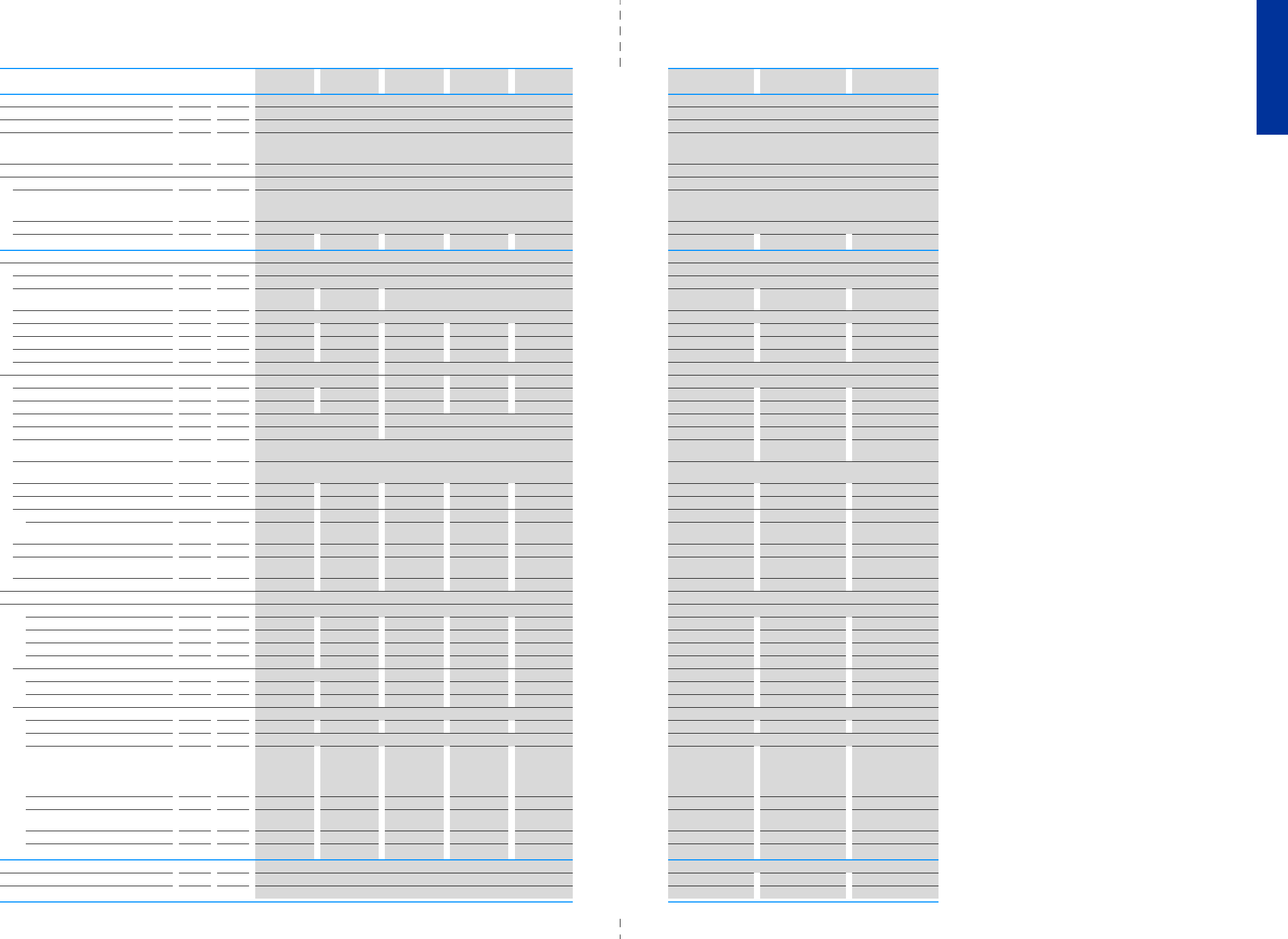
48 PowerXL™ variable frequency drives
DC1 (Ue: 115 V AC, single-phase, U2: 115 V AC, single-phase/230 V AC, 3 phase)
CA04020001Z-EN-INT www.eaton.eu CA04020001Z-EN-INT www.eaton.eu
PowerXL™ variable frequency drives
DC1 (Ue: 230 V AC, single-phase, U2: 230 V AC, single-phase)
DC1, DA1
DC1 (Ue: 115 V AC, single-phase, U2: 115 V AC, single-phase/230 V AC, 3 phase)DC1 (Ue: 230 V AC , single-phase , U2: 230 V AC, single-phase)
DC1-S17D0… DC1-S1011… DC1-1D2D3… DC1-1D4D3… DC1-1D5D3… DC1-S24D3… DC1-S27D0…
General
Climatic proofing w%< 95%, average relative humidity (RH), non-condensing (EN50178) < 95%, average relative humidity (RH), non-condensing (EN50178)
Mounting position Vertical Vertical
Altitude m 0 - 1000 m above sea level
above 1000m with 1 % performance reduction per 100m
max. 4000 m
0 - 1000 m above sea level
above 1000m with 1 % performance reduction per 100m
max. 4000 m
Protection against direct contact BGV A3 (VBG4, finger- and back-of-hand proof) BGV A3 (VBG4, finger- and back-of-hand proof)
Radio interference level
Radio interference class (EMC) C1, C2, C3, depending on the motor cable length, the connected load, and ambient conditions.
External radio interference suppression filters (optional) may be necessary.
C1, C2, C3, depending on the motor cable length, the connected load, and
ambient conditions. External radio interference suppression filters (optional)
may be necessary.
Environment (EMC) 1st and 2nd environments 1st and 2nd environments
longest permissible length of motor cable I m 25 (200) 25 (200) 25 (200) 25 (200) 25 (200) 25 (200) 25 (200) 25 (200)
Main circuit
Supply
Rated operational voltage Ue115 V AC, single-phase 230 V AC, 1-phase
Notes --The mains voltage of 115V is raised to 230V (output
voltage) through an internal voltage double connection.
- - -
Mains voltage (50/60Hz) ULN V110 (-10%) - 115 (+10%) 200 (-10%) - 240 (+10%)
Input current ILN T8.5 12.5 11 19 25 69.3 14
Supply frequency fLN Hz 50/60 50/60 50/60 50/60 50/60 50/60 50/60 50/60
Frequency range fLN Hz 48 - 62 Hz 48 - 62 Hz 48 - 62 Hz 48 - 62 Hz 48 - 62 Hz 48 - 62 Hz 48 - 62 Hz 48 - 62 Hz
Mains switch-on frequency Maximum of one time every 30 seconds Maximum of one time every 30 seconds Maximum of one time every 30 seconds
Power section
Overload current for 60 s every 600 s ILA10.5 15.75 3.45 6.45 8.7 6.45 10.5 15.75
Starting current for 2 s ILA12.25 18.38 4.03 7.53 10.15 7.53 12.25 18.38
Output voltage with VeU2115 V AC, single-phase 230 V AC, 3-phase 230 V AC, single-phase 230 V AC, single-phase 230 V AC, single-phase
Output Frequency f2Hz 0 - 50 Hz (max. 120 Hz) 0 - 50 Hz (max. 500 Hz) 0 - 50 Hz (max. 120 Hz) 0 - 50 Hz (max. 120 Hz) 0 - 50 Hz (max. 120 Hz)
Switching frequency fPWM kHz 16
(adjustable 4 - 32)
16
(adjustable 4 - 32)
16
(adjustable 4 - 32)
16
(adjustable 4 - 32)
Operation Mode U/f control
Slip compensation
U/f control
Slip compensation
Frequency resolution (setpoint value) fHz 0.1 0.1 0.1 0.1 0.1 0.1 0.1 0.1
Rated operational current IeA 7 10.5 2.3 4.3 5.8 4.3 710.5
Power loss
Heat dissipation at rated operational
current
PVW18.5 22 18.5 37.5 44 18.5 37.5 44
Efficiency %95 96 95 95 96 95 95 96
Maximum leakage current to ground (PE)
without motor
IPE mA 2.49 2.49 < 1 < 1 < 1 2.49 2.49 2.49
Frame size FS1 FS2 FS1 FS1 FS2 FS1 FS1 FS2
Motor feeder
Assigned motor rating
at 115 V, 50 Hz P kW 0.37 0.55 - - - - - -
at 230 V, 50 Hz P kW --0.37 0.75 1.1 - - -
110 - 120 V, 60 Hz P HP 0.5 0.75 - - - - - -
at 220 - 240 V, 60 Hz P HP --0.5 11.5 - - -
Apparent power
Apparent power at rated operation 230 V S kVA 0 0 - - - 0.99 1.61 2.42
Apparent power at rated operation 240 V S kVA 0 0 - - - 1.03 1.68 2.52
Braking function
Standard braking torque --max. 30% MNmax. 30% MNmax. 30% MN- - -
DC braking torque max. 100% of rated operational current Ie, variable max. 100% of rated operational current Ie, variable
Braking torque with external braking
resistance
-max. 100% rated
operational
current Ie, with
external braking
resistance
- - max. 100% rated
operational
current Ie, with
external braking
resistance
- - max. 100% rated
operational current Ie,
with external braking
resistance
minimum external braking resistance Rmin -47 - - 47 - - 47
Switch-on threshold for the braking
transistor
UDC V - - - - 390 V DC - - 390 V DC
DC braking % I/Ie- - - - - - - -
Braking torque % I/Ie- - - - - - - -
Control section
External control voltage UcV24 V DC (max. 100 mA) 24 V DC (max. 100 mA) 24 V DC (max. 100 mA) 24 V DC (max. 100 mA)
Reference voltage UsV10 V DC (max. 10 mA) 10 V DC (max. 10 mA) 10 V DC (max. 10 mA) 10 V DC (max. 10 mA)
Note 1) With a switching frequency of 4 kHz and an ambient air temperature of +40°C or +50°C for IP20/NEMA 0
49
DC1 (Ue: 115 V AC, single-phase, U2: 115 V AC, single-phase/230 V AC, 3 phase) DC1 (Ue: 115 V AC, single-phase, U2: 115 V AC, single-phase/230 V AC, 3 phase)

50 PowerXL™ variable frequency drives
DC1 (Ue: 230 V AC, single-phase, U2: 230 V AC, 3 phase)
CA04020001Z-EN-INT www.eaton.eu CA04020001Z-EN-INT www.eaton.eu
PowerXL™ variable frequency drives
DC1 (Ue: 230 V AC, 3 phase, U2: 230 V AC, 3 phase)
DC1, DA1
DC1 (Ue: 230 V AC, single-phase, U2: 230 V AC, 3 phase)DC1 (Ue: 230 V AC, 3 phase, U2: 230 V AC, 3 ph ase)
Part no. DC1-122D3… DC1-124D3… DC1-127D0… DC1-12011… DC1-12015… DC1-322D3… DC1-324D3… DC1-327D0… DC1-32011… DC1-32018…
General
Climatic proofing w%< 95%, average relative humidity (RH), non-condensing (EN50178) < 95%, average relative humidity (RH), non-condensing (EN50178)
Mounting position Vertical Vertical
Altitude m 0 - 1000 m above sea level
above 1000m with 1 % performance reduction per 100m
max. 4000 m
0 - 1000 m above sea level
above 1000m with 1 % performance reduction per 100m
max. 4000 m
Protection against direct contact BGV A3 (VBG4, finger- and back-of-hand proof) BGV A3 (VBG4, finger- and back-of-hand proof)
Radio interference level
Radio interference class (EMC) C1, C2, C3, depending on the motor cable length, the connected load, and ambient conditions.
External radio interference suppression filters (optional) may be necessary.
C1, C2, C3, depending on the motor cable length, the connected load, and ambient conditions.
External radio interference suppression filters (optional) may be necessary.
Environment (EMC) 1st and 2nd environments 1st and 2nd environments
longest permissible length of motor cable I m 25 (200) 25 (200) 25 (200) 25 (200) 25 (200) 25 (200) 25 (200) 25 (200) 25 (200) 25 (200)
Main circuit
Supply
Rated operational voltage Ue230 V AC, 1-phase 230 V AC, 3-phase 230 V AC, 3-phase 230 V AC, 3-phase 230 V AC, 3-phase 230 V AC, 3-phase
Mains voltage (50/60Hz) ULN V200 (-10%) - 240 (+10%) 200 (-10%) - 240 (+10%)
Input current ILN T 5 8.5 13.9 19.5 30.5 34.5 7.3 11 18.8
Supply frequency fLN Hz 50/60 50/60 50/60 50/60 50/60 50/60 50/60 50/60 50/60 50/60
Frequency range fLN Hz 48 - 62 Hz 48 - 62 Hz 48 - 62 Hz 48 - 62 Hz 48 - 62 Hz 48 - 62 Hz 48 - 62 Hz 48 - 62 Hz 48 - 62 Hz 48 - 62 Hz
Mains switch-on frequency Maximum of one time every 30 seconds Maximum of one time every 30 seconds
Power section
Overload current for 60 s every 600 s ILA3.45 6.45 10.5 15.75 22.5 3.45 6.45 10.5 15.75 27
Starting current for 2 s ILA4.03 7.53 12.25 18.38 26.25 4.03 7.53 12.25 18.38 31.5
Output voltage with VeU2230 V AC, 3-phase 230 V AC, 3-phase
Output Frequency f2Hz 0 - 50 Hz
(max. 500 Hz)
0 - 50 Hz
(max. 500 Hz)
0 - 50 Hz
(max. 500 Hz)
0 - 50 Hz
(max. 500 Hz)
0 - 50 Hz
(max. 500 Hz)
0 - 50 Hz
(max. 500 Hz)
0 - 50 Hz
(max. 500 Hz)
0 - 50 Hz
(max. 500 Hz)
0 - 50 Hz
(max. 500 Hz)
0 - 50 Hz
(max. 500 Hz)
Switching frequency fPWM kHz 16
(adjustable 4 - 32)
8
(adjustable 4 - 24)
16
(adjustable 4 - 32)
16
(adjustable 4 - 32)
16
(adjustable 4 - 32)
16
(adjustable 4 - 32)
8
(adjustable 4 - 24)
Operation Mode U/f control
Slip compensation
U/f control
Slip compensation
Frequency resolution (setpoint value) fHz 0.1 0.1 0.1 0.1 0.1 0.1 0.1 0.1 0.1 0.1
Rated operational current IeA2.3 4.3 710.5 15 2.3 4.3 710.5 18
Power loss
Heat dissipation at rated operational
current
PVW18.5 45.75 63 103.4 160 14.8 39.75 61.5 90.2 160
Efficiency %95 93.9 95.8 95.3 96 96 94.7 95.9 95.9 96
Maximum leakage current to ground (PE)
without motor
IPE mA 2.49 2.49 2.49 2.49 < 1 < 1 < 1 < 1 < 1 < 1
Frame size FS1 FS1 FS2 FS2 FS3 FS1 FS1 FS2 FS2 FS3
Motor feeder
Assigned motor rating
at 230 V, 50 Hz P kW 0.37 0.75 1.5 2.2 40.37 0.75 1.5 2.2 4
at 220 - 240 V, 60 Hz P HP 0.5 1 2 3 5 0.5 1 2 3 5
Apparent power
Apparent power at rated operation 230 V S kVA 0.92 1.71 2.79 4.18 5.98 0.92 1.71 2.79 4.18 7.17
Apparent power at rated operation 240 V S kVA 0.96 1.79 2.91 4.36 6.24 0.96 1.79 2.91 4.36 7.48
Braking function
Standard braking torque max. 30% MNmax. 30% MNmax. 30% MNmax. 30% MNmax. 30% MNmax. 30% MNmax. 30% MNmax. 30% MNmax. 30% MNmax. 30% MN
DC braking torque max. 100% of rated operational current Ie, variable max. 100% of rated operational current Ie, variable
Braking torque with external braking
resistance
- - max. 100% rated operational current Ie, with external
braking resistance
-max. 100% rated operational
current Ie, with external braking
resistance
max. 100% rated operational
current Ie, with external braking
resistance
max. 100% rated operational
current Ie, with external braking
resistance
minimum external braking resistance Rmin - - 100 47 47 -100 47 47
Switch-on threshold for the braking
transistor
UDC V - - 390 V DC 390 V DC 390 V DC -390 V DC 390 V DC 390 V DC
DC braking % I/Ie- - - - - - - - -
Braking torque % I/Ie- - - - - - - - -
Control section
External control voltage UcV24 V DC (max. 100 mA) 24 V DC (max. 100 mA) 24 V DC (max. 100 mA) 24 V DC (max. 100 mA) 24 V DC (max. 100 mA) 24 V DC (max. 100 mA)
Reference voltage UsV10 V DC (max. 10 mA) 10 V DC (max. 10 mA) 10 V DC (max. 10 mA) 10 V DC (max. 10 mA) 10 V DC (max. 10 mA) 10 V DC (max. 10 mA)
Note 1) With a switching frequency of 4 kHz and an ambient air temperature of +40°C or +50°C for IP20/NEMA 0
51
DC1 (Ue: 230 V AC, single-phase, U2: 230 V AC, 3 phase) DC1 (Ue: 230 V AC, single-phase, U2: 230 V AC, 3 phase)
52 PowerXL™ variable frequency drives
DC1 (Ue: 400 V AC, 3 phase, U2: 400 V AC, 3 phase)
CA04020001Z-EN-INT www.eaton.eu CA04020001Z-EN-INT www.eaton.eu
PowerXL™ variable frequency drives
DC1 (Ue: 400 V AC, 3 phase, U2: 400 V AC, 3 phase)
DC1, DA1
DC1 (Ue: 400 V A C, 3 phase, U2: 400 V AC, 3 phase)DC1 (Ue: 400 V AC, 3 phase, U2: 400 V AC, 3 phase)
Part no. DC1-342D2… DC1-344D1… DC1-345D8… DC1-349D5… DC1-34014… DC1-34018… DC1-34024…
General
Climatic proofing w%< 95%, average relative humidity (RH), non-condensing (EN50178) < 95%, average relative humidity (RH), non-condensing (EN50178)
Mounting position Vertical Vertical
Altitude m 0 - 1000 m above sea level
above 1000m with 1 % performance reduction per 100m
max. 4000 m
0 - 1000 m above sea level
above 1000m with 1 % performance reduction per 100m
max. 4000 m
Protection against direct contact BGV A3 (VBG4, finger- and back-of-hand proof) BGV A3 (VBG4, finger- and back-of-hand proof)
Radio interference level
Radio interference class (EMC) C1, C2, C3, depending on the motor cable length, the connected load, and ambient conditions.
External radio interference suppression filters (optional) may be necessary.
C1, C2, C3, depending on the motor cable length, the connected load, and ambient conditions.
External radio interference suppression filters (optional) may be necessary.
Environment (EMC) 1st and 2nd environments 1st and 2nd environments
longest permissible length of motor cable I m 25 (200) 25 (200) 25 (200) 25 (200) 25 (200) 25 (200) 25 (200)
Main circuit
Supply
Rated operational voltage Ue400 V AC, 3-phase 400 V AC, 3-phase 400 V AC, 3-phase 400 V AC, 3-phase 400 V AC, 3-phase 400 V AC, 3-phase 400 V AC, 3-phase
Mains voltage (50/60Hz) ULN V380 (-10%) - 480
(+10%)
380 (-10%) - 480
(+10%)
380 (-10%) - 480
(+10%)
380 (-10%) - 480
(+10%)
380 (-10%) - 480 (+10%) 380 (-10%) - 480 (+10%) 380 (-10%) - 480 (+10%)
Input current ILN T2.4 4.3 6.1 9.8 14.6 18.1 24.7
Supply frequency fLN Hz 50/60 50/60 50/60 50/60 50/60 50/60 50/60
Frequency range fLN Hz 48 - 62 Hz 48 - 62 Hz 48 - 62 Hz 48 - 62 Hz 48 - 62 Hz 48 - 62 Hz 48 - 62 Hz
Mains switch-on frequency Maximum of one time every 30 seconds Maximum of one time every 30 seconds
Power section
Overload current for 60 s every 600 s ILA3.3 6.15 8.7 14.25 21 27 36
Starting current for 2 s ILA3.85 7.18 10.15 16.63 24.5 31.5 42
Output voltage with VeU2400 V AC, 3-phase 400 V AC, 3-phase 400 V AC, 3-phase 400 V AC, 3-phase 400 V AC, 3-phase 400 V AC, 3-phase 400 V AC, 3-phase
Output Frequency f2Hz 0 - 50 Hz (max. 500 Hz) 0 - 50 Hz (max. 500 Hz) 0 - 50 Hz (max. 500 Hz) 0 - 50 Hz (max. 500 Hz) 0 - 50 Hz (max. 500 Hz) 0 - 50 Hz (max. 500 Hz) 0 - 50 Hz (max. 500 Hz)
Switching frequency fPWM kHz 16
(adjustable 4 - 32)
16
(adjustable 4 - 32)
16
(adjustable 4 - 32)
16
(adjustable 4 - 32)
8
(adjustable 4 - 24)
8
(adjustable 4 - 24)
8
(adjustable 4 - 24)
Operation Mode U/f control
Slip compensation
U/f control
Slip compensation
Frequency resolution (setpoint value) fHz 0.1 0.1 0.1 0.1 0.1 0.1 0.1
Rated operational current IeA2.2 4.1 5.8 9.5 14 18 24
Power loss
Heat dissipation at rated operational
current
PVW63.75 76.5 101.2 136 209 300 297
Efficiency %91.5 94.9 95.4 96.6 96.2 97 97.3
Maximum leakage current to ground (PE)
without motor
IPE mA < 1 < 1 < 1 < 1 < 1 < 1 2.49
Frame size FS1 FS2 FS2 FS2 FS3 FS3 FS3
Motor feeder
Assigned motor rating
at 400 V, 50 Hz P kW 0.75 1.5 2.2 45.5 7.5 11
at 440 - 480 V, 60 Hz P HP 1 2 3 5 7.5 10 15
Apparent power
Apparent power at rated operation 400 V S kVA 1.52 2.84 4.02 6.58 9.67 12.47 16.63
Apparent power at rated operation 480 V S kVA 1.83 3.41 4.82 7.9 11.64 14.96 19.95
Braking function
Standard braking torque max. 30% MNmax. 30% MNmax. 30% MNmax. 30% MNmax. 30% MNmax. 30% MNmax. 30% MN
DC braking torque max. 100% of rated operational current Ie, variable max. 100% of rated operational current Ie, variable
Braking torque with external braking
resistance
-max. 100% rated operational current Ie, with external braking resistance max. 100% rated operational current Ie, with external braking resistance
minimum external braking resistance Rmin -200 200 100 100 47 47
Switch-on threshold for the braking
transistor
UDC V - 780 V DC 780 V DC 780 V DC 780 V DC 780 V DC 780 V DC
DC braking % I/Ie- - - - - - -
Braking torque % I/Ie- - - - - - -
Control section
External control voltage UcV24 V DC (max. 100 mA) 24 V DC (max. 100 mA) 24 V DC (max. 100 mA) 24 V DC (max. 100 mA) 24 V DC (max. 100 mA) 24 V DC (max. 100 mA) 24 V DC (max. 100 mA)
Reference voltage UsV10 V DC (max. 10 mA) 10 V DC (max. 10 mA) 10 V DC (max. 10 mA) 10 V DC (max. 10 mA) 10 V DC (max. 10 mA) 10 V DC (max. 10 mA) 10 V DC (max. 10 mA)
Note 1) With a switching frequency of 4 kHz and an ambient air temperature of +40°C or +50°C for IP20/NEMA 0
53
DC1 (Ue: 400 V AC, 3 phase, U2: 400 V AC, 3 phase) DC1 (Ue: 400 V AC, 3 phase, U2: 400 V AC, 3 phase)

54 PowerXL™ variable frequency drives
DA1 (Ue: 230 V AC, single-phase, U2: 230 V AC, single-phase)
CA04020001Z-EN-INT www.eaton.eu CA04020001Z-EN-INT www.eaton.eu
PowerXL™ variable frequency drives
DA1 (Ue: 230 V AC, 3 phase, U2: 230 V AC, 3 phase)
DC1, DA1
DA1 (Ue: 230 V AC, single-p hase, U2: 230 V AC, single-phase)DA1 (Ue: 230 V AC, 3 phase, U2: 230 V AC, 3 phase)
Typ DA1-124D3… DA1-127D0… DA1-12011… DA1-324D3… DA1-327D0… DA1-32011… DA1-32018… DA1-32024…
General
Climatic proofing w%< 95%, average relative humidity (RH), non-condensing (EN50178) < 95%, average relative humidity (RH), non-condensing (EN50178)
Mounting position Vertical Vertical
Altitude m 0 - 1000 m above sea level
above 1000m with 1 % performance reduction per 100m
max. 4000 m
0 - 1000 m above sea level
above 1000m with 1 % performance reduction per 100m
max. 4000 m
Protection against direct contact BGV A3 (VBG4, finger- and back-of-hand proof) BGV A3 (VBG4, finger- and back-of-hand proof)
Radio interference level
Radio interference class (EMC) C1, C2, C3, depending on the motor cable length, the connected load, and ambient conditions.
External radio interference suppression filters (optional) may be necessary.
C1, C2, C3, depending on the motor cable length, the connected load, and ambient conditions.
External radio interference suppression filters (optional) may be necessary.
Environment (EMC) 1st and 2nd environments 1st and 2nd environments
longest permissible length of motor cable I m 25 (200) 25 (200) 25 (200) 25 (200) 25 (200) 25 (200) 25 (200) 25 (200)
Main circuit
Supply
Rated operational voltage Ue230 V AC, 1-phase 230 V AC, 1-phase 230 V AC, 1-phase 230 V AC, 3-phase 230 V AC, 3-phase 230 V AC, 3-phase 230 V AC, 3-phase 230 V AC, 3-phase
Mains voltage (50/60Hz) ULN V200 (-10%) - 240 (+10%) 200 (-10%) - 240 (+10%)
Input current ILN T8.5 13.9 19.5 4.5 7.3 11 18.8 24.8
Supply frequency fLN Hz 50/60 50/60 50/60 50/60 50/60 50/60 50/60 50/60
Frequency range fLN Hz 48 - 62 Hz 48 - 62 Hz 48 - 62 Hz 48 - 62 Hz 48 - 62 Hz 48 - 62 Hz 48 - 62 Hz 48 - 62 Hz
Mains switch-on frequency Maximum of one time every 30 seconds Maximum of one time every 30 seconds
Power section
Overload current for 60 s every 600 s ILA6.45 10.5 15.75 6.45 10.5 15.75 27 36
Starting current for 4 s ILA8.6 14 21 8.6 14 21 36 48
Output voltage with VeU2230 V AC, 3-phase 230 V AC, 3-phase 230 V AC, 3-phase 230 V AC, 3-phase 230 V AC, 3-phase 230 V AC, 3-phase 230 V AC, 3-phase 230 V AC, 3-phase
Output Frequency f2Hz 0 - 50 Hz (max. 500 Hz) 0 - 50 Hz (max. 500 Hz) 0 - 50 Hz (max. 500 Hz) 0 - 50 Hz (max. 500 Hz) 0 - 50 Hz (max. 500 Hz) 0 - 50 Hz (max. 500 Hz) 0 - 50 Hz (max. 500 Hz) 0 - 50 Hz (max. 500 Hz)
Switching frequency fPWM kHz 16
(adjustable 4 - 32)
16
(adjustable 4 - 32)
16
(adjustable 4 - 32)
16
(adjustable 4 - 32)
16
(adjustable 4 - 32)
16
(adjustable 4 - 32)
16
(adjustable 4 - 24)
16
(adjustable 4 - 16)
Operation Mode U/f control
Slip compensation
sensorless vector control (SLV)
Vector control with feedback (CLV)
U/f control
Slip compensation
sensorless vector control (SLV)
Vector control with feedback (CLV)
Frequency resolution (setpoint value) fHz 0.1 0.1 0.1 0.1 0.1 0.1 0.1 0.1
Rated operational current IeA4.3 710.5 4.3 710.5 18 24
Power loss
Heat dissipation at rated operational
current
PVW45.75 63 103.4 39.75 61.5 90.2 160 170.5
Efficiency %93.9 95.8 95.3 94.7 95.9 95.9 96 96.9
Maximum leakage current to ground (PE)
without motor
IPE mA 2.49 2.49 2.49 1.73 1.73 1.73 0.93 0.93
Frame size FS2 FS2 FS2 FS2 FS2 FS2 FS3 FS3
Motor feeder
Assigned motor rating
at 230 V, 50 Hz P kW 0.75 1.5 2.2 0.75 1.5 2.2 45.5
at 220 - 240 V, 60 Hz P HP 1 2 3 1 2 3 5 7.5
Apparent power
Apparent power at rated operation 230 V S kVA 1.71 2.79 4.18 1.71 2.79 4.18 7.17 9.56
Apparent power at rated operation 240 V S kVA 1.79 2.91 4.36 1.79 2.91 4.36 7.48 9.98
Braking function
Standard braking torque max. 30% MNmax. 30% MNmax. 30% MNmax. 30% MNmax. 30% MNmax. 30% MNmax. 30% MNmax. 30% MN
DC braking torque max. 100% of rated operational current Ie, variable max. 100% of rated operational current Ie, variable
Braking torque with external braking
resistance
max. 100% rated operational current Ie, with external braking resistance max. 100% rated operational current Ie, with external braking resistance
minimum external braking resistance Rmin 100 50 35 100 50 35 20 20
Switch-on threshold for the braking
transistor
UDC V390 V DC 390 V DC 390 V DC 390 V DC 390 V DC 390 V DC 390 V DC 390 V DC
Control section
External control voltage UcV24 V DC (max. 100 mA) 24 V DC (max. 100 mA) 24 V DC (max. 100 mA) 24 V DC (max. 100 mA) 24 V DC (max. 100 mA) 24 V DC (max. 100 mA) 24 V DC (max. 100 mA) 24 V DC (max. 100 mA)
Reference voltage UsV10 V DC (max. 10 mA) 10 V DC (max. 10 mA) 10 V DC (max. 10 mA) 10 V DC (max. 10 mA) 10 V DC (max. 10 mA) 10 V DC (max. 10 mA) 10 V DC (max. 10 mA) 10 V DC (max. 10 mA)
Note 1) With a switching frequency of 4 kHz and an ambient air temperature of +40°C or +50°C for IP20/NEMA 0
55
DA1 (Ue: 230 V AC, single-phase, U2: 230 V AC, 3 phase) DA1 (Ue: 230 V AC, 3 phase, U2: 230 V AC, 3 phase)
56 PowerXL™ variable frequency drives
DA1 (Ue: 400 V AC, 3 phase, U2: 400 V AC, 3 phase)
CA04020001Z-EN-INT www.eaton.eu CA04020001Z-EN-INT www.eaton.eu
PowerXL™ variable frequency drives
DA1 (Ue: 400 V AC, 3 phase, U2: 400 V AC, 3 phase)
DC1, DA1
DA1 (Ue: 400 V AC, 3 phase, U2: 400 V AC, 3 p hase)DA1 (Ue: 400 V AC, 3 phase, U2: 400 V AC, 3 phase)
Part no. DA1-342D2… DA1-344D1FB… DA1-345D8… DA1-349D5… DA1-34014… DA1-34018… DA1-34024… DA1-34030… DA1-34039… DA1-34046…
General
Climatic proofing w%< 95%, average relative humidity (RH), non-condensing (EN50178) < 95%, average relative humidity (RH), non-condensing (EN50178)
Mounting position Vertical Vertical
Altitude m 0 - 1000 m above sea level
above 1000m with 1 % performance reduction per 100m
max. 4000 m
0 - 1000 m above sea level
above 1000m with 1 % performance reduction per 100m
max. 4000 m
Protection against direct contact BGV A3 (VBG4, finger- and back-of-hand proof) BGV A3 (VBG4, finger- and back-of-hand proof)
Radio interference level
Radio interference class (EMC) C1, C2, C3, depending on the motor cable length, the connected load, and ambient conditions.
External radio interference suppression filters (optional) may be necessary.
C1, C2, C3, depending on the motor cable length, the connected load, and ambient conditions.
External radio interference suppression filters (optional) may be necessary.
Environment (EMC) 1st and 2nd environments 1st and 2nd environments
longest permissible length of motor cable I m 25 (200) 25 (200) 25 (200) 25 (200) 25 (200) 25 (200) 25 (200) 25 (200) 25 (200) 25 (200)
Main circuit
Supply
Rated operational voltage Ue400 V AC, 3-phase 400 V AC, 3-phase 400 V AC, 3-phase 400 V AC, 3-phase 400 V AC, 3-phase 400 V AC, 3-phase 400 V AC, 3-phase 400 V AC, 3-phase 400 V AC, 3-phase 400 V AC, 3-phase
Mains voltage (50/60Hz) ULN V380 (-10%) - 480 (+10%) 380 (-10%) - 480 (+10%)
Input current ILN T2.4 4.3 6.1 9.8 14.6 18.1 24.7 30.8 40 47.1
Supply frequency fLN Hz 50/60 50/60 50/60 50/60 50/60 50/60 50/60 50/60 50/60 50/60
Frequency range fLN Hz 48 - 62 Hz 48 - 62 Hz 48 - 62 Hz 48 - 62 Hz 48 - 62 Hz 48 - 62 Hz 48 - 62 Hz 48 - 62 Hz 48 - 62 Hz 48 - 62 Hz
Mains switch-on frequency Maximum of one time every 30 seconds Maximum of one time every 30 seconds
Power section
Overload current for 60 s every 600 s ILA3.3 6.15 8.7 14.25 21 27 36 45 58.5 69
Starting current for 4 s ILA4.4 8.2 11.6 19 28 36 48 60 78 92
Output voltage with VeU2400 V AC, 3-phase 400 V AC, 3-phase 400 V AC, 3-phase 400 V AC, 3-phase 400 V AC, 3-phase 400 V AC, 3-phase 400 V AC, 3-phase 400 V AC, 3-phase 400 V AC, 3-phase 400 V AC, 3-phase
Output Frequency f2Hz 0 - 50 Hz (max. 500 Hz) 0 - 50 Hz (max. 500 Hz) 0 - 50 Hz (max. 500 Hz) 0 - 50 Hz (max. 500 Hz) 0 - 50 Hz (max. 500 Hz) 0 - 50 Hz (max. 500 Hz) 0 - 50 Hz (max. 500 Hz) 0 - 50 Hz (max. 500 Hz) 0 - 50 Hz (max. 500 Hz) 0 - 50 Hz (max. 500 Hz)
Switching frequency fPWM kHz 8
(adjustable 4 - 24)
8
(adjustable 4 - 24)
8
(adjustable 4 - 32)
8
(adjustable 4 - 32)
8
(adjustable 4 - 24)
8
(adjustable 4 - 24)
8
(adjustable 4 - 24)
8
(adjustable 4 - 24)
8
(adjustable 4 - 24)
8
(adjustable 4 - 24)
Operation Mode U/f control
Slip compensation
sensorless vector control (SLV)
Vector control with feedback (CLV)
U/f control
Slip compensation
sensorless vector control (SLV)
Vector control with feedback (CLV)
Frequency resolution (setpoint value) fHz 0.1 0.1 0.1 0.1 0.1 0.1 0.1 0.1 0.1 0.1
Rated operational current IeA2.2 4.1 5.8 9.5 14 18 24 30 39 46
Power loss
Heat dissipation at rated operational
current
PVW63.75 76.5 101.2 136 209 300 297 375 444 506
Efficiency %91.5 94.9 95.4 96.6 96.2 97 97.3 97.5 97.6 97.7
Maximum leakage current to ground (PE)
without motor
IPE mA 4.65 4.65 4.65 4.65 1.55 1.55 2.47 2.47 2.47 2.47
Frame size FS2 FS2 FS2 FS2 FS3 FS3 FS4 FS4 FS4 FS4
Motor feeder
Assigned motor rating
at 400 V, 50 Hz P kW 0.75 1.5 2.2 45.5 7.5 11 15 18.5 22
at 440 - 480 V, 60 Hz P HP 1 2 3 5 7.5 10 15 20 25 30
Apparent power
Apparent power at rated operation 400 V S kVA 1.52 2.84 4.02 6.58 9.67 12.47 16.63 20.78 27.02 31.87
Apparent power at rated operation 480 V S kVA 1.83 3.41 4.82 7.9 11.64 14.96 19.95 24.94 32.42 38.24
Braking function
Standard braking torque max. 30% MNmax. 30% MNmax. 30% MNmax. 30% MNmax. 30% MNmax. 30% MNmax. 30% MNmax. 30% MNmax. 30% MNmax. 30% MN
DC braking torque max. 100% of rated operational current Ie, variable max. 100% of rated operational current Ie, variable
Braking torque with external braking
resistance
max. 100% rated operational current Ie, with external braking resistance max. 100% rated operational current Ie, with external braking resistance
minimum external braking resistance Rmin 400 200 150 100 75 50 40 22 22 22
Switch-on threshold for the braking
transistor
UDC V780 V DC 780 V DC 780 V DC 780 V DC 780 V DC 780 V DC 780 V DC 780 V DC 780 V DC 780 V DC
Control section
External control voltage UcV24 V DC (max. 100 mA) 24 V DC (max. 100 mA) 24 V DC (max. 100 mA) 24 V DC (max. 100 mA) 24 V DC (max. 100 mA) 24 V DC (max. 100 mA) 24 V DC (max. 100 mA) 24 V DC (max. 100 mA) 24 V DC (max. 100 mA) 24 V DC (max. 100 mA)
Reference voltage UsV10 V DC (max. 10 mA) 10 V DC (max. 10 mA) 10 V DC (max. 10 mA) 10 V DC (max. 10 mA) 10 V DC (max. 10 mA) 10 V DC (max. 10 mA) 10 V DC (max. 10 mA) 10 V DC (max. 10 mA) 10 V DC (max. 10 mA) 10 V DC (max. 10 mA)
Note 1) With a switching frequency of 4 kHz and an ambient air temperature of +40°C or +50°C for IP20/NEMA 0
57
DA1 (Ue: 400 V AC, 3 phase, U2: 400 V AC, 3 phase) DA1 (Ue: 400 V AC, 3 phase, U2: 400 V AC, 3 phase)
58 PowerXL™ variable frequency drives
DA1 (Ue: 230 V AC, 3 phase, U2: 230 V AC, 3 phase)
CA04020001Z-EN-INT www.eaton.eu CA04020001Z-EN-INT www.eaton.eu
PowerXL™ variable frequency drives
DA1 (Ue: 230 V AC, 3 phase, U2: 230 V AC, 3 phase)
DC1, DA1
DA1 (Ue: 230 V AC, 3 phase, U2: 230 V AC, 3 p hase)DA1 (Ue: 230 V AC, 3 phase, U2: 230 V AC, 3 phase)
Part no. DA1-34090…
General
Climatic proofing w%< 95%, average relative humidity (RH), non-condensing (EN50178) < 95%, average relative humidity (RH), non-condensing (EN50178)
Mounting position Vertical Vertical
Altitude m 0 - 1000 m above sea level
above 1000m with 1 % performance reduction per 100m
max. 4000 m
0 - 1000 m above sea level
above 1000m with 1 % performance reduction per 100m
max. 4000 m
Protection against direct contact BGV A3 (VBG4, finger- and back-of-hand proof) BGV A3 (VBG4, finger- and back-of-hand proof)
Radio interference level
Radio interference class (EMC) C1, C2, C3, depending on the motor cable length, the connected load, and ambient conditions.
External radio interference suppression filters (optional) may be necessary.
C1, C2, C3, depending on the motor cable length, the connected load, and ambient conditions.
External radio interference suppression filters (optional) may be necessary.
Environment (EMC) 1st and 2nd environments 1st and 2nd environments
longest permissible length of motor cable I m 25 (200) 25 (200) 25 (200) 25 (200) 25 (200) 25 (200) 25 (200) 25 (200) 25 (200)
Main circuit
Supply
Rated operational voltage Ue400 V AC, 3-phase 400 V AC, 3-phase 400 V AC, 3-phase 400 V AC, 3-phase 400 V AC, 3-phase 400 V AC, 3-phase 400 V AC, 3-phase 400 V AC, 3-phase 400 V AC, 3-phase
Mains voltage (50/60Hz) ULN V380 (-10%) - 480 (+10%) 380 (-10%) - 480 (+10%)
Input current ILN T62.8 73.8 92.2 112.5 153.2 183.7 205.9 244.5 307.8
Supply frequency fLN Hz 50/60 50/60 50/60 50/60 50/60 50/60 50/60 50/60 50/60
Frequency range fLN Hz 48 - 62 Hz 48 - 62 Hz 48 - 62 Hz 48 - 62 Hz 48 - 62 Hz 48 - 62 Hz 48 - 62 Hz 48 - 62 Hz 48 - 62 Hz
Mains switch-on frequency Maximum of one time every 30 seconds Maximum of one time every 30 seconds
Power section
Overload current for 60 s every 600 s ILA91.5 105 135 165 225 270 303 360 453
Starting current for 4 s ILA122 140 180 220 300 360 404 480 604
Output voltage with VeU2400 V AC, 3-phase 400 V AC, 3-phase 400 V AC, 3-phase 400 V AC, 3-phase 400 V AC, 3-phase 400 V AC, 3-phase 400 V AC, 3-phase 400 V AC, 3-phase 400 V AC, 3-phase
Output Frequency f2Hz 0 - 50 Hz (max. 500 Hz) 0 - 50 Hz (max. 500 Hz) 0 - 50 Hz (max. 500 Hz) 0 - 50 Hz (max. 500 Hz) 0 - 50 Hz (max. 500 Hz) 0 - 50 Hz (max. 500 Hz) 0 - 50 Hz (max. 500 Hz) 0 - 50 Hz (max. 500 Hz) 0 - 50 Hz (max. 500 Hz)
Switching frequency fPWM kHz 8
(adjustable 4 - 24)
8
(adjustable 4 - 24)
4
(adjustable 4 - 16)
4
(adjustable 4 - 16)
4
(adjustable 4 - 12)
4
(adjustable 4 - 8)
4
(adjustable 4 - 16)
4
(adjustable 4 - 12)
4
(adjustable 4 - 8)
Operation Mode U/f control
Slip compensation
sensorless vector control (SLV)
Vector control with feedback (CLV)
U/f control
Slip compensation
sensorless vector control (SLV)
Vector control with feedback (CLV)
Frequency resolution (setpoint value) fHz 0.1 0.1 0.1 0.1 0.1 0.1 0.1 0.1 0.1
Rated operational current IeA61 72 90 110 150 180 202 240 302
Power loss
Heat dissipation at rated operational
current
PVW840 925 1080 1210 1575 1800 2090 2376 3040
Efficiency %97.2 97.5 97.6 97.8 97.9 98 98.1 98.2 98.1
Maximum leakage current to ground (PE)
without motor
IPE mA 0.49 0.49 2.68 2.68 2.68 2.68 4.75 4.75 4.75
Frame size FS5 FS5 FS6 FS6 FS6 FS6 FS7 FS7 FS7
Motor feeder
Assigned motor rating
at 400 V, 50 Hz P kW 30 37 45 55 75 90 110 132 160
at 440 - 480 V, 60 Hz P HP 40 50 60 75 100 150 175 200 250
Apparent power
Apparent power at rated operation 400 V S kVA 42.26 48.5 62.35 76.21 103.92 124.71 139.95 166.28 209.23
Apparent power at rated operation 480 V S kVA 50.71 58.2 74.82 91.45 124.71 149.65 167.94 199.53 251.08
Braking function
Standard braking torque max. 30% MNmax. 30% MNmax. 30% MNmax. 30% MNmax. 30% MNmax. 30% MNmax. 30% MNmax. 30% MNmax. 30% MN
DC braking torque max. 100% of rated operational current Ie, variable max. 100% of rated operational current Ie, variable
Braking torque with external braking
resistance
max. 100% rated operational current Ie, with external braking resistance max. 100% rated operational current Ie, with external braking resistance
minimum external braking resistance Rmin 12 12 6 6 6 6 6 6 6
Switch-on threshold for the braking
transistor
UDC V780 V DC 780 V DC 780 V DC 780 V DC 780 V DC 780 V DC 780 V DC 780 V DC 780 V DC
Control section
External control voltage UcV24 V DC (max. 100 mA) 24 V DC (max. 100 mA) 24 V DC (max. 100 mA) 24 V DC (max. 100 mA) 24 V DC (max. 100 mA) 24 V DC (max. 100 mA) 24 V DC (max. 100 mA) 24 V DC (max. 100 mA) 24 V DC (max. 100 mA)
Reference voltage UsV10 V DC (max. 10 mA) 10 V DC (max. 10 mA) 10 V DC (max. 10 mA) 10 V DC (max. 10 mA) 10 V DC (max. 10 mA) 10 V DC (max. 10 mA) 10 V DC (max. 10 mA) 10 V DC (max. 10 mA) 10 V DC (max. 10 mA)
Note 1) With a switching frequency of 4 kHz and an ambient air temperature of +40°C or +50°C for IP20/NEMA 0
59
DA1 (Ue: 400 V AC, 3 phase, U2: 400 V AC, 3 phase) DA1 (Ue: 400 V AC, 3 phase, U2: 400 V AC, 3 phase)
60 PowerXL™ variable frequency drives
DA1 (Ue: 230 V AC, 3 phase, U2: 230 V AC, 3 phase)
CA04020001Z-EN-INT www.eaton.eu CA04020001Z-EN-INT www.eaton.eu
PowerXL™ variable frequency drives
DA1 (Ue: 230 V AC, 3 phase, U2: 230 V AC, 3 phase)
DC1, DA1
Typ DA1-32039… DA1-32046… DA1-32061… DA1-32072… DA1-32090… DA1-32110… DA1-32150… DA1-32180… DA1-32202… DA1-32248…
General
Climatic proofing w%< 95%, average relative humidity (RH), non-condensing (EN50178) < 95%, average relative humidity (RH), non-condensing (EN50178)
Mounting position Vertical Vertical
Altitude m 0 - 1000 m above sea level
above 1000m with 1 % performance reduction per 100m
max. 4000 m
0 - 1000 m above sea level
above 1000m with 1 % performance reduction per 100m
max. 4000 m
Protection against direct contact BGV A3 (VBG4, finger- and back-of-hand proof) BGV A3 (VBG4, finger- and back-of-hand proof)
Radio interference level
Radio interference class (EMC) C1, C2, C3, depending on the motor cable length, the connected load, and ambient conditions.
External radio interference suppression filters (optional) may be necessary.
C1, C2, C3, depending on the motor cable length, the connected load, and ambient conditions.
External radio interference suppression filters (optional) may be necessary.
Environment (EMC) 1st and 2nd environments 1st and 2nd environments
longest permissible length of motor cable I m 25 (200) 25 (200) 25 (200) 25 (200) 25 (200) 25 (200) 25 (200) 25 (200) 25 (200) 25 (200)
Main circuit
Supply
Rated operational voltage Ue230 V AC,
3-phase
230 V AC,
3-phase
230 V AC,
3-phase
230 V AC,
3-phase
230 V AC,
3-phase
230 V AC,
3-phase
230 V AC,
3-phase
230 V AC,
3-phase
230 V AC,
3-phase
230 V AC,
3-phase
Mains voltage (50/60Hz) ULN V200 (-10%) - 240 (+10%) 200 (-10%) - 240 (+10%)
Input current ILN T40 47.1 62.4 74.1 92.3 112.7 153.5 183.8 206.2 252.8
Supply frequency fLN Hz 50/60 50/60 50/60 50/60 50/60 50/60 50/60 50/60 50/60 50/60
Frequency range fLN Hz 48 - 62 Hz 48 - 62 Hz 48 - 62 Hz 48 - 62 Hz 48 - 62 Hz 48 - 62 Hz 48 - 62 Hz 48 - 62 Hz 48 - 62 Hz 48 - 62 Hz
Mains switch-on frequency Maximum of one time every 30 seconds Maximum of one time every 30 seconds
Power section
Overload current for 60 s every 600 s ILA45 69 91.5 108 135 165 225 270 303 372
Starting current for 4 s ILA60 92 122 144 180 220 300 360 404 496
Output voltage with VeU2230 V AC, 3-phase 230 V AC, 3-phase 230 V AC, 3-phase 230 V AC, 3-phase 230 V AC, 3-phase 230 V AC, 3-phase
Output Frequency f2Hz 0 - 50 Hz
(max. 500 Hz)
0 - 50 Hz
(max. 500 Hz)
0 - 50 Hz
(max. 500 Hz)
0 - 50 Hz
(max. 500 Hz)
0 - 50 Hz
(max. 500 Hz)
0 - 50 Hz
(max. 500 Hz)
0 - 50 Hz
(max. 500 Hz)
0 - 50 Hz
(max. 500 Hz)
0 - 50 Hz
(max. 500 Hz)
0 - 50 Hz
(max. 500 Hz)
Switching frequency fPWM kHz 8
(adjustable 4 - 24)
4
(adjustable 4 - 16)
4
(adjustable 4 - 16)
4
(adjustable 4 - 12)
4
(adjustable 4 - 8)
4
(adjustable 4 - 16)
4
(adjustable 4 - 12)
Operation Mode U/f control
Slip compensation
sensorless vector control (SLV)
Vector control with feedback (CLV)
U/f control
Slip compensation
sensorless vector control (SLV)
Vector control with feedback (CLV)
Frequency resolution (setpoint value) fHz 0.1 0.1 0.1 0.1 0.1 0.1 0.1 0.1 0.1 0.1
Rated operational current IeA39 46 61 72 90 110 150 180 202 248
Power loss
Heat dissipation at rated operational
current
PVW187.5 264 345 518 550 720 814 945 1100 1425
Efficiency %97.5 97.6 97.7 97.2 97.5 97.6 97.8 97.9 98 98.1
Maximum leakage current to ground (PE)
without motor
IPE mA 1.42 1.42 0.28 0.28 1.54 1.54 1.54 1.54 2.74 2.74
Frame size FS4 FS4 FS5 FS5 FS6 FS6 FS6 FS6 FS7 FS7
Motor feeder
Assigned motor rating
at 230 V, 50 Hz P kW 7.5 11 15 18.5 22 30 45 55 55 75
at 220 - 240 V, 60 Hz P HP 10 15 20 25 30 40 50 60 75 100
Apparent power
Apparent power at rated operation 230 V S kVA 11.95 18.33 24.3 28.68 35.85 43.82 59.76 71.71 80.47 98.8
Apparent power at rated operation 240 V S kVA 12.47 19.12 25.36 29.93 37.41 45.73 62.35 74.82 83.97 103.09
Braking function
Standard braking torque max. 30% MNmax. 30% MNmax. 30% MNmax. 30% MNmax. 30% MNmax. 30% MNmax. 30% MNmax. 30% MNmax. 30% MNmax. 30% MN
DC braking torque max. 100% of rated operational current Ie, variable max. 100% of rated operational current Ie, variable
Braking torque with external braking
resistance
max. 100% rated operational current Ie, with external braking resistance max. 100% rated operational current Ie, with external braking resistance
minimum external braking resistance Rmin 22 12 12 6 6 6 6 6 6 6
Switch-on threshold for the braking
transistor
UDC V390 V DC 390 V DC 390 V DC 390 V DC 390 V DC 390 V DC 390 V DC 390 V DC 390 V DC 390 V DC
Control section
External control voltage UcV24 V DC (max. 100 mA) 24 V DC (max. 100 mA) 24 V DC (max. 100 mA) 24 V DC (max. 100 mA) 24 V DC (max. 100 mA) 24 V DC (max. 100 mA)
Reference voltage UsV10 V DC (max. 10 mA) 10 V DC (max. 10 mA) 10 V DC (max. 10 mA) 10 V DC (max. 10 mA) 10 V DC (max. 10 mA) 10 V DC (max. 10 mA)
Note 1) With a switching frequency of 4 kHz and an ambient air temperature of +40°C or +50°C for IP20/NEMA 0
61
DA1 (Ue: 230 V AC, 3 phase, U2: 230 V AC, 3 phase) DA1 (Ue: 230 V AC, 3 phase, U2: 230 V AC, 3 phase)

62 PowerXL™ variable frequency drives
Mains chokes, motor chokes
CA04020001Z-EN-INT www.eaton.eu
Mains chokes, motor chokes
Technical data
DX-LN1… DX-LN3… DX-LM3…
General
Standards IEC/EN 61558-2-20-2000,
VDE 0570 Part 2-20/2001-04,
UL, CSA
IEC/EN 61558-2-20-2000,
VDE 0570 Part 2-20/2001-04,
UL, CSA
IEC/EN 61558-2-20-2000,
VDE 0570 Part 2-20/2001-04,
UL, CSA
Operating temperature °C -25 to +40, up to 70 with current
derating (see the note)
-25 to +40, up to 70 with current
derating (see the note)
-25 to +40, up to 70 with current
derating (see the note)
Storage temperature °C -25 - +85 -25 - +85 -25 - +85
Mechanical shock resistance g 11 ms2/15
3 shocks
11 ms2/15
3 shocks
11 ms2/15
3 shocks
Vibration resistance g 1 (0 - 150 Hz) 1 (0 - 150 Hz) 1 (0 - 150 Hz)
Vibration 0.35 mm at 10 - 55 Hz 0.35 mm at 10 - 55 Hz 0.35 mm at 10 - 55 Hz
Altitude m 0 – 1000 above sea level,
up to 5000 with current reduction
(see notes)
0 – 1000 above sea level,
up to 5000 with current reduction
(see notes)
0 – 1000 above sea level,
up to 5000 with current reduction
(see notes)
Mounting position Standing vertically, suspended
horizontally
Standing vertically, suspended
horizontally
Standing vertically, suspended
horizontally
Free surrounding areas MM < 50 < 50 < 50
Protection type IP20 (terminal) IP20 (terminal) IP20 (terminal)
Rated duty factor % DF 100 100 100
Weight kg 0.7 1.5 1.5
Electrical data
Rated operational voltage 1 AC 230 V 3 AC 400 V 3 AC 400 V
Max. supply voltage V AC 260 V + 0% (50/60 Hz) 550 V + 0% (50/60 Hz) 750 V + 0% (50/60 Hz)
Operating frequency f Hz 50/60 50/60 0…200
Insulation class BBB
Connection
Terminations
Connection lugs - ( 50 A) ( 63 A)
PE stud
PowerXL™ variable frequency drives
Mains chokes, motor chokes
CA04020001Z-EN-INT www.eaton.eu
63
DC1, DA1
Part no. Rated
operational
current
Induct-
ance
Maximum
heat
dissipatio
n
Cu factor Voltage sag Connection Drilling Tightening
torque
Weight
IeL PvUkTerminal Terminal Connection
lug
AmH Wkg %mm2AWG mm2mm Nm kg
Mains choke
Rated operational voltage 1 AC 230 V
DX-LN1-006 5.8 5.05 90,09 4 4 20 - 10 - - 0.8 0.7
DX-LN1-009 8.6 3.41 11 0,11 4 4 20 - 10 - - 0.8 0.7
DX-LN1-013 13 2.25 12 0,18 4 4 20 - 10 - - 0.8 1.5
DX-LN1-018 18 1.63 17 0,27 4 4 20 - 10 - - 0.8 1.5
DX-LN1-024 24 1.22 20 0,33 4 4 20 - 10 - - 0.8 2
DX-LN1-032 32 0.92 24 0,00 4 4 20 - 10 - 0 0.8 3
Rated operational voltage 3 AC 400 V
DX-LN3-004 3.9 7.51 17 0,25 4 4 20 - 10 - - 0.8 1.5
DX-LN3-006 64.9 19 0,34 4 4 20 - 10 - - 0.8 1.5
DX-LN3-010 10 2.94 33 0,45 4 4 20 - 10 - - 0.8 2.2
DX-LN3-016 16 1.84 44 0,53 4 4 20 - 10 - - 0.8 2.9
DX-LN3-025 25 1.18 57 0,90 4 4 20 - 10 - - 0.8 4.8
DX-LN3-040 40 0.64 59 0,91 2.5 10 20 - 6 - - 1.5 4.8
DX-LN3-050 50 0.37 58 1,08 2.5 --Cu 15 x 2 7 3 5.9
DX-LN3-060 60 0.31 60 1,51 2.5 --Cu 15 x 2 7 3 5.9
DX-LN3-080 80 0.23 86 1,67 2.5 --Cu 20 x 3 9 6 7.3
DX-LN3-100 100 0.18 101 1,68 2.5 --Cu 20 x 3 9 6 10.2
DX-LN3-120 120 0.15 100 2,26 2.5 --Cu 25 x 5 11 10 10.2
DX-LN3-160 160 0.11 140 2,35 2.5 --Cu 25 x 5 11 10 12.3
DX-LN3-200 200 0.09 154 3,81 2.5 --Cu 25 x 5 11 10 14.9
DX-LN3-250 250 0.07 155 4,26 2.5 --Cu 40 x 5 14 15.5 20.6
DX-LN3-300 300 0.06 196 4,28 2.5 --Cu 40 x 5 14 15.5 20.6
DX-LN3-303 303 0.06 230 0,00 2.5 --Cu 40 x 5 14 15.5 20.6
DX-LN3-370 370 0.05 290 0,00 2.5 --Cu 40 x 5 14 15.5 24.3
DX-LN3-450 450 0.04 300 0,00 2.5 --Cu 40 x 10 14 15.5 23.8
Part no. Rated
operational
current
Induct-
ance
max. heat dissipation
(pulse frequency)
Cu factor Connection Drilling Tightening
torque
Weight
(3 kHz) (5 kHz) (12 kHz) Terminal Terminal Connection
lug
IeL PvPvPv
AmH WWW kg mm2AWG mm2mm Nm kg
Motor chokes
Rated operational voltage 3 AC 400 V
DX-LM3-005 5 2 12 14 24 0,29 420 - 10 - - 0.8 1.5
DX-LM3-008 84.1 32 46 54 1,09 420 - 10 - - 0.8 4.8
DX-LM3-011 11 345 66 71 1,23 420 - 10 - - 0.8 4.8
DX-LM3-016 16 1.5 50 75 78 0,88 420 - 10 - - 0.8 4.8
DX-LM3-035 35 175 114 116 2,30 420 - 10 - - 0.8 7.3
DX-LM3-050 50 0.6 110 157 168 3,60 10 20 - 6 - - 1.5 12.3
DX-LM3-063 63 0.5 130 190 193 3,01 --Cu 15 x 2 7 3 14.9
DX-LM3-080 80 0.5 132 206 206 5,88 --Cu 20 x 2 9 6 20.6
DX-LM3-100 100 0.45 177 279 294 10,10 --Cu 20 x 2 9 6 31
DX-LM3-150 150 0.35 293 418 424 8,22 --Cu 25 x 5 11 10 45
DX-LM3-180 180 0.3 418 298 439 14,75 --Cu 25 x 5 11 10 45
DX-LM3-220 220 0.2 344 512 517 11,37 --Cu 40 x 5 14 15.5 45
DX-LM3-260 260 0.15 358 526 520 11,10 --Cu 40 x 5 14 15.5 45
DX-LM3-303 303 0.15 685 - - 0,00 --Cu 40 x 5 14 15.5 48.7
DX-LM3-370 370 0.12 685 - - 0,00 --Cu 40 x 5 14 15.5 61.7
DX-LM3-450 450 0.1 730 - - 0,00 --Cu 40 x 10 14 15.5 81.7
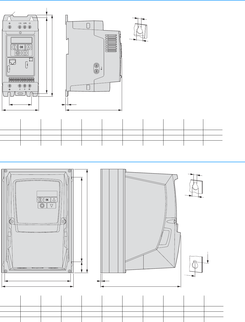
64 PowerXL™ variable frequency drives
DC1
CA04020001Z-EN-INT www.eaton.eu
DC1
Dimensions
DC1, sizes FS1 - FS3, degree of protection IP20/NEMA 0
DC1, sizes FS1 - FS3, degree of protection IP66/NEMA 4X
c
c1
VAR
EMC
b
b1
a
a1
1234567891011
⌀1
⌀2
⌀
b2
a a1 b b1 b2 c c1 12WeightSize
mm (inch) mm (inch) mm (inch) mm (inch) mm (inch) mm (inch) mm (inch) mm (inch) mm (inch) kg
81 (3.19) 50 (1.97) 184 (7.24) 170 (6.69) 7 (0.28) 124 (4.88) 4 (0.16) 6 (0.24) 12 (0.47) 1.1 FS1
107 (4.21) 75 (2.95) 231 (9.09) 215 (8.46) 8 (0.31) 152 (5.98) 5 (0.2) 6 (0.24) 12 (0.47) 2.6 FS2
131 (5.16) 100 (3.94) 273 (10.75) 255 (10.04) 8.5 (0.33) 175 (6.89) 5 (0.2) 6 (0.24) 12 (0.47) 4 FS3
b
b1b2
a c
a1 c1
⌀1
⌀2
a1
b1
a a1 b b1 b2 c c1 12WeightSize
mm (inch) mm (inch) mm (inch) mm (inch) mm (inch) mm (inch) mm (inch) mm (inch) mm (inch) kg (lbs)
161 (6.34) 148.5 (5.85) 232 (9.13) 189 (7.44) 25 (0.98) 184 (7.24) 3.5 (0.14) 4 (0.15) 8 (0.31) 2.5 (5.51) FS1
188 (7.4) 176 (6.93) 257 (10.12) 200 (7.87) 28.5 (1.12) 192 (7.56) 3.5 (0.14) 4.2 (0.16) 8.5 (0.33) 4.7 (10.36) FS2
210.5 (8.29) 197.5 (7.78) 310 (12.2) 251.5 (9.9) 33.4 (1.31) 234 (9.21) 3.5 (0.14) 4.2 (0.16) 8.5 (0.33) 7.9 (17.42) FS3
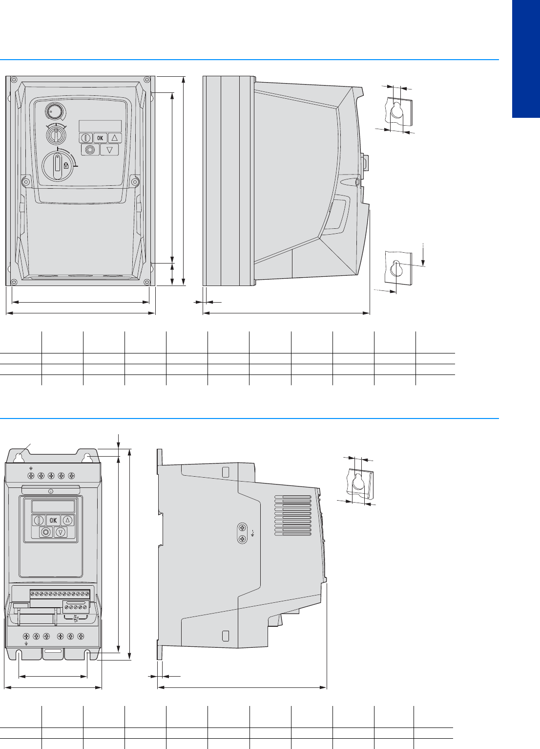
PowerXL™ variable frequency drives
DC1, DA1
CA04020001Z-EN-INT www.eaton.eu
65
DC1, DA1
DC1, DA1
DC1, sizes FS1 - FS3, degree of protection IP66/NEMA 4X, with local controls
DA1, sizes FS2 - FS3, degree of protection IP20/NEMA 0
REV FWD
0
ON
OFF
PWR
b
a c
a1 c1
b1b2
a1
b1
⌀1
⌀2
a a1 b b1 b2 c c1 12WeightSize
mm (inch) mm (inch) mm (inch) mm (inch) mm (inch) mm (inch) mm (inch) mm (inch) mm (inch) kg (lbs)
161 (6.34) 148.5 (5.85) 232 (9.13) 189 (7.44) 25 (0.98) 184 (7.24) 3.5 (0.14) 4 (0.15) 8 (0.31) 2.8 (6.17) FS1
188 (7.4) 176 (6.93) 257 (10.12) 200 (7.87) 28.5 (1.12) 192 (7.56) 3.5 (0.14) 4.2 (0.16) 8.5 (0.33) 5 (11.02) FS2
210.5 (8.29) 197.5 (7.78) 310 (12.2) 251.5 (9.9) 33.4 (1.31) 234 (9.21) 3.5 (0.14) 4.2 (0.16) 8.5 (0.33) 8.2 (18.08) FS3
EMC
VAR
c
⌀1
⌀2
L2/N L3DC- L1/L
DC+ BR U V W
12345678910111213
14 15 16 17 18
COM
b1
b
a
a1 c1
⌀
b2
a a1 b b1 b2 c c1 12WeightSize
mm (inch) mm (inch) mm (inch) mm (inch) mm (inch) mm (inch) mm (inch) mm (inch) mm (inch) kg
107 (4.21) 75 (2.95) 231 (9.09) 215 (8.46) 8 (0.31) 186 (7.32) 5 (0.2) 6 (0.24) 12 (0.47) 1.8 FS2
131 (5.16) 100 (3.94) 273 (10.75) 255 (10.04) 8.5 (0.33) 204 (8.03) 5 (0.2) 6 (0.24) 12 (0.47) 3.5 FS3
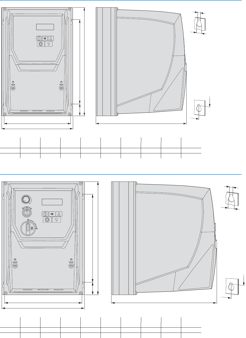
66 PowerXL™ variable frequency drives
DA1
CA04020001Z-EN-INT www.eaton.eu
DA1
DA1, sizes FS2 - FS3, degree of protection IP66/NEMA 4X
DA1, sizes FS2 - FS3, degree of protection IP66/NEMA 4X, with local controls
b
b1
a
c
b2
a1
⌀1
⌀2
a1
b1
a a1 b b1 b2 c 12 Weight Size
mm (inch) mm (inch) mm (inch) mm (inch) mm (inch) mm (inch) mm (inch) mm (inch) kg (lbs)
188 (7.4) 176 (6.93) 257 (10.12) 200 (7.87) 20 (0.79) 239.3 (9.42) 4.2 (0.16) 8.5 (0.33) 4.5 (10.4) FS2
211 (8.29) 198 (7.78) 310 (12.2) 252 (9.9) 25 (0.98) 266.3 (10.48) 4.2 (0.16) 8.5 (0.33) 7 (15.9) FS3
b
b1
a
c
b2
a1
⌀1
⌀2
a1
b1
REV FWD
0
ON
OFF
PWR
a a1 b b1 b2 c 12 Weight Size
mm (inch) mm (inch) mm (inch) mm (inch) mm (inch) mm (inch) mm (inch) mm (inch) kg (lbs)
188 (7.4) 176 (6.93) 257 (10.12) 200 (7.87) 20 (0.79) 239.3 (9.42) 4.2 (0.16) 8.5 (0.33) 4.8 (10.6) FS2
211 (8.29) 198 (7.78) 310 (12.2) 252 (9.9) 25 (0.98) 266.3 (10.48) 4.2 (0.16) 8.5 (0.33) 7.3 (16.1) FS3
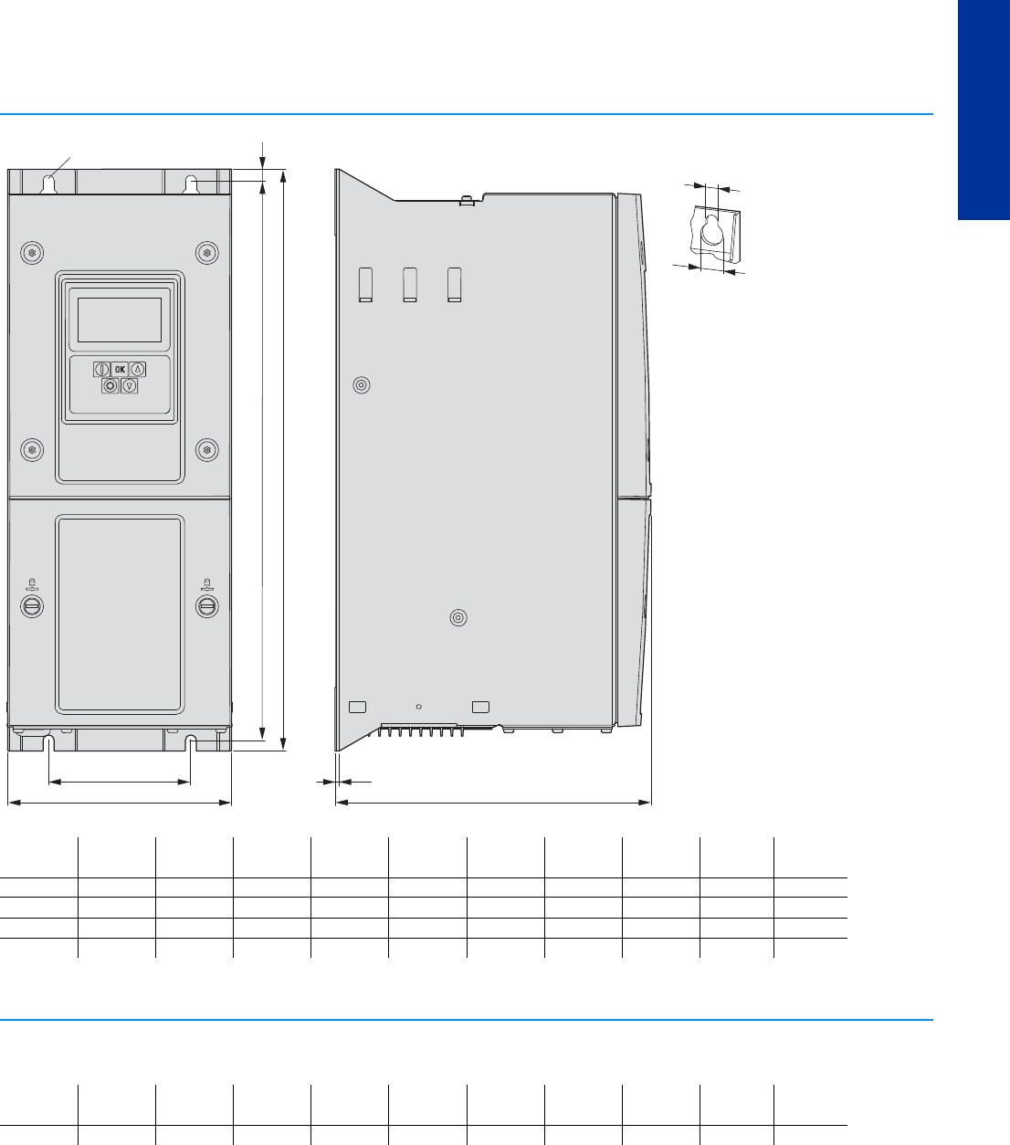
PowerXL™ variable frequency drives
DA1
CA04020001Z-EN-INT www.eaton.eu
67
DC1, DA1
DA1, sizes FS4 - FS7, degree of protection IP55
DA1, size FS8, degree of protection IP40
Control panel version
b
a1
c
c1
a
b1 b2
⌀1
⌀2
⌀
a a1 b b1 b2 c c1 12WeightSize
mm (inch) mm (inch) mm (inch) mm (inch) mm (inch) mm (inch) mm (inch) mm (inch) mm (inch) kg
171 (6.73) 110 (4.33) 450 (17.72) 428 (16.85) 9 (0.35) 240 (9.45) 2 (0.08) 8 (0.31) 15 (0.59) 11.5 FS4
235 (9.25) 175 (6.89) 540 (20.28) 515 (20.28) 12 (0.47) 270 (10.63) 2 (0.08) 8 (0.31) 15 (0.59) 22.5 FS5
330 (12.99) 200 (7.87) 865 (34.06) 840 (33.07) 15 (0.59) 330 (12.99) 2 (0.08) 11 (0.43) 22 (0.87) 50 FS6
330 (12.99) 200 (7.87) 1280 (50.39) 1255 (44.41) 15 (0.59) 360 (14.17) 2 (0.08) 11 (0.43) 22 (0.87) 80 FS7
a a1 b b1 b2 c c1 12WeightSize
mm (inch) mm (inch) mm (inch) mm (inch) mm (inch) mm (inch) mm (inch) mm (inch) mm (inch) kg
500 (19.69) 350 (13.78) 2000 (78.74) 1950 (76.77) 33 (1.3) 516 (20.31) 2 (0.08) 18 (0.71) 35 (1.38) 270 FS8
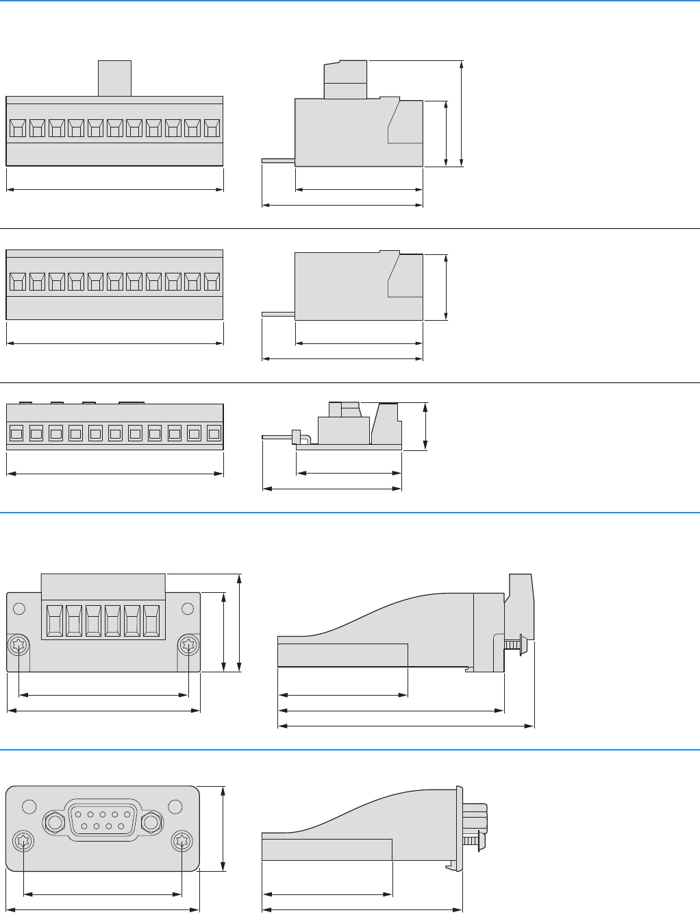
68 PowerXL™ variable frequency drives
Accessories
CA04020001Z-EN-INT www.eaton.eu
Accessories
Expansion modules for DC1
DXC-EXT-IO110
DXC-EXT-IO230
DXC-EXT-2RO1AO
DXC-EXT-2RO
DXC-EXT-LOCSIM
Expansion modules for DA1
DXA-EXT-3DI1RO
DXA-EXT-3RO
DXA-EXT-ENCOD
Fieldbus module for DA1
DX-NET-PROFIBUS
56 mm (2.2")
18 mm (0.71")
24 mm (0.95")
39 mm (1.54")
41 mm (1.61")
56 mm (2.2")
18 mm (0.71")
39 mm (1.54")
41 mm (1.61")
27 mm (1.06")
36 mm (1.42")
56 mm (2.2")
12.3 mm
(0.48")
48 mm (1.89")
41 mm (1.61")
60 mm (2.36")
70 mm (2.75")
33.7 mm (1.33")
23 mm (0.91")
21 mm (0.83")
OP ST
PROFIBUS DP-V1
51.8 mm (2.04")48 mm (1.89")
41 mm (1.61") 33.7 mm (1.33")
22.3 mm (0.88")
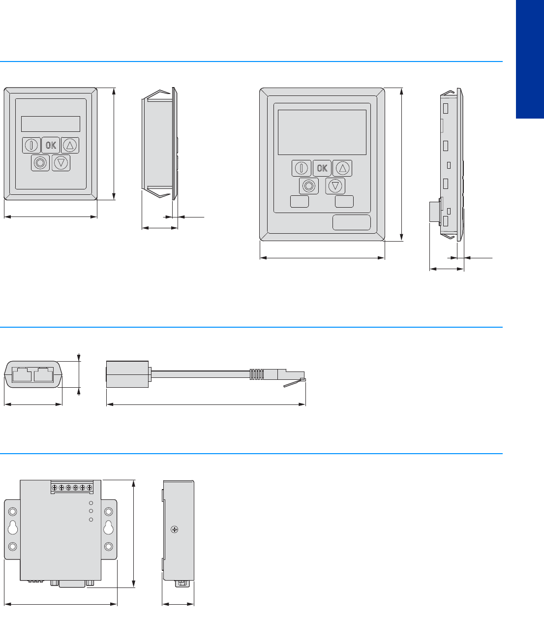
PowerXL™ variable frequency drives
Accessories
CA04020001Z-EN-INT www.eaton.eu
69
DC1, DA1
External keypad
DX-KEY-LED DX-KEY-OLED
Cable and splitter
DX-SPL-RJ45-2SL1PL
Interface converter
DX-COM-PCKIT
66 mm (2.6")
81 mm (3.19")
26 mm
(1.02")
4 mm
(0.16")
110 mm (4.33")
90 mm (3.54")
23.5 mm
(0.93")
4.5 mm
(0.18")
Hand Auto
42 mm (1.65")
19 mm
(0.75")
145 mm (5.7")
81 mm (3.19")
77 mm (3.03")
23 mm
(0.91")
634521
PWR
USB
RxD
SerialSW
TxD

70 PowerXL™ variable frequency drives
Mains chokes, motor chokes
CA04020001Z-EN-INT www.eaton.eu
Mains chokes, motor chokes
Mains chokes
DX-LN1-…
Mains chokes, motor chokes
DX-LN3-004…-DX-LN3-040
DX-LM3-005…-DX-LM3-050
b2
b1
o d
a
a1
PE
12
c1 ± 5 mm
(c1 ± 0.20”)
b ± 5 mm
(b ± 0.20”)
c ± 5 mm
(c ± 0.20”)
a a1 b b1 b2 c c1 d Weight
mm (inch) mm (inch) mm (inch) mm (inch) mm (inch) mm (inch) mm (inch) mm (inch) kg
DX-LN1-006 66 (2.6) 50 (1.97) 71 (2.8) 44 (1.73) 55 (2.17) 80 (3.15) 61 (2.36) 4.5 x 8 (0.18 x 0.31) 0.7
DX-LN1-009 66 (2.6) 50 (1.97) 71 (2.8) 44 (1.73) 55 (2.17) 80 (3.15) 61 (2.36) 4.5 x 8 (0.18 x 0.31) 0.7
DX-LN1-013 84 (3.31) 64 (2.52) 67 (2.64) 47 (1.85) 60 (2.36) 90 (3.54) 75 (2.95) 4.8 x 8 (0.18 x 0.31) 1.5
DX-LN1-018 84 (3.31) 64 (2.52) 67 (2.64) 47 (1.85) 60 (2.36) 90 (3.54) 75 (2.95) 4.8 x 8 (0.18 x 0.31) 1.5
DX-LN1-024 84 (3.31) 64 (2.52) 81 (3.19) 61 (2.4) 74 (2.91) 90 (3.54) 75 (2.95) 4.8 x 8 (0.18 x 0.31) 2
DX-LN1-032 105 (4.13) 84 (3.31) 102 (4.02) 65 (2.56) 81 (3.19) 121 (4.76) 94 (3.7) 5.8 x 11 (0.23 x 0.43) 3
a1
a
b1
b2
od
W1W2
V1 V2
U1 U2
PE PE
b ± 5 mm (b ± 0.20”)
c1 ± 5 mm
(c1 ± 0.20”)
c ± 5 mm
(c ± 0.20”)
aa1bb1b2cc1d Weight
mm (inch) mm (inch) mm (inch) mm (inch) mm (inch) mm (inch) mm (inch) mm (inch) kg
DX-LN3-004 115 (4.53) 100 (3.94) 66 (2.6) 50 (1.97) 66 (2.6) 118 (4.65) 84 (3.31) 5 x 10 (0.2 x 0.39) 1.5
DX-LN3-006 115 (4.53) 100 (3.94) 66 (2.6) 50 (1.97) 66 (2.6) 118 (4.65) 84 (3.31) 5 x 10 (0.2 x 0.39) 1.5
DX-LN3-010 140 (5.51) 125 (4.92) 61 (2.4) 50 (1.97) 61 (2.4) 138 (5.43) 105 (4.13) 5 x 10 (0.2 x 0.39) 2.2
DX-LN3-016 140 (5.51) 125 (4.92) 71 (2.8) 50 (1.97) 71 (2.8) 138 (5.43) 105 (4.13) 5 x 10 (0.2 x 0.39) 2.9
DX-LN3-025 195 (7.68) 175 (6.89) 104 (4.09) 50 (1.97) 76.5 (3.01) 175 (6.89) 134 (5.28) 8 x 13 (0.31 x 0.51) 4.8
DX-LN3-040 195 (7.68) 175 (6.89) 104 (4.09) 50 (1.97) 76.5 (3.01) 188 (7.4) 134 (5.28) 8 x 13 (0.31 x 0.51) 4.8
DX-LM3-005 115 (4.53) 100 (3.94) 66 (2.6) 50 (1.97) 66 (2.6) 118 (4.65) 84 (3.31) 5 x 10 (0.2 x 0.39) 1.5
DX-LM3-008 195 (7.68) 175 (6.89) 104 (4.09) 50 (1.97) 76.5 (3.01) 175 (6.89) 134 (5.28) 8 x 13 (0.31 x 0.51) 4.8
DX-LM3-011 195 (7.68) 175 (6.89) 104 (4.09) 50 (1.97) 76.5 (3.01) 175 (6.89) 134 (5.28) 8 x 13 (0.31 x 0.51) 4.8
DX-LM3-016 195 (7.68) 175 (6.89) 104 (4.09) 50 (1.97) 76.5 (3.01) 175 (6.89) 134 (5.28) 8 x 13 (0.31 x 0.51) 4.8
DX-LM3-035 220 (8.66) 200 (7.87) 132 (5.2) 75 (2.95) 101.5 (4) 195 (7.68) 160 (6.3) 8 x 13 (0.31 x 0.51) 7.3
DX-LM3-050 270 (10.63) 250 (9.84) 106 (4.17) 75 (2.95) 96 (3.78) 228 (8.98) 198 (7.8) 8 x 13 (0.31 x 0.51) 12.3
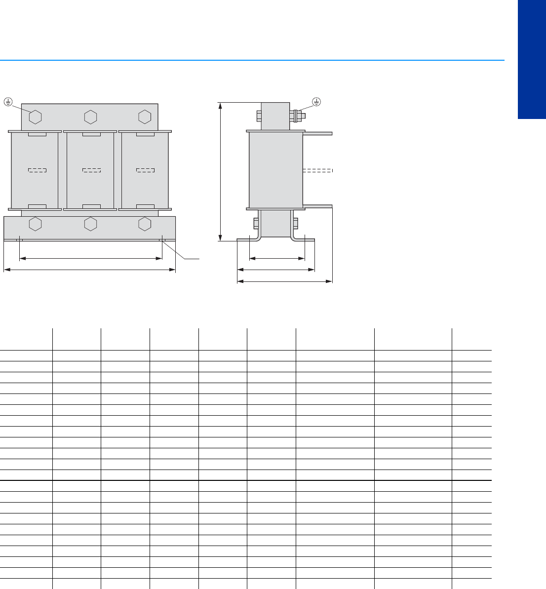
PowerXL™ variable frequency drives
Mains chokes, motor chokes
CA04020001Z-EN-INT www.eaton.eu
71
DC1, DA1
Mains chokes, motor chokes
Mains chokes, motor chokes
DX-LN3-050…-DX-LN3-450
DX-LM3-063…-DX-LM3-450
Height tolerance depends on gap
The position of connection lugs U2-V2-W2 depends on the coil material and can deviate from the position illustrated here.
⌀d b1
a1
a
PE
U1 V1 W1
U2 V2 W2
U2 V2 W2
b2
PE
b ± 10 mm (b ± 0.39”)
c ± 5 mm
(c ± 0.20”)
a a1 b b1 b2 c d Weight
mm (inch) mm (inch) mm (inch) mm (inch) mm (inch) mm (inch) mm (inch) kg
DX-LN3-050 195 (7.68) 175 (6.89) 105 (4.13) 75 (2.95) 91.5 (3.6) 132 ±5 (5.2 ±0.2) 8 x 13 (0.31 x 0.51) 5.9
DX-LN3-060 195 (7.68) 175 (6.89) 105 (4.13) 75 (2.95) 91.5 (3.6) 132 ±5 (5.2 ±0.2) 8 x 13 (0.31 x 0.51) 5.9
DX-LN3-080 220 (8.66) 200 (7.87) 110 (4.33) 50 (1.97) 81.5 (3.21) 160 ±5 (6.3 ±0.2) 8 x 13 (0.31 x 0.51) 7.3
DX-LN3-100 220 (8.66) 200 (7.87) 130 (5.12) 75 (2.95) 101.5 (4) 160 ±5 (6.3 ±0.2) 8 x 13 (0.31 x 0.51) 10.2
DX-LN3-120 220 (8.66) 200 (7.87) 130 (5.12) 75 (2.95) 101.5 (4) 160 ±5 (6.3 ±0.2 ) 8 x 13 (0.31 x 0.51) 10.2
DX-LN3-160 270 (10.63) 250 (9.84) 125 (4.92) 75 (2.95) 96 (3.75) 200 ±5 (7.87 ±0.2) 8 x 13 (0.31 x 0.51) 12.3
DX-LN3-200 270 (10.63) 250 (9.84) 155 (6.1) 100 (3.94) 120 (4.72) 202 ±5 (7.95 ±0.2) 8 x 13 (0.31 x 0.51) 14.9
DX-LN3-250 270 (10.63) 250 (9.84) 155 (6.1) 100 (3.94) 125 (4.92) 210 ±5 (8.27 ±0.2) 10 x 18 (0.39 x 0.71) 20.6
DX-LN3-300 270 (10.63) 250 (9.84) 155 (6.1) 100 (3.94) 125 (4.92) 210 ±5 (8.27 ±0.2) 10 x 18 (0.39 x 0.71) 20.6
DX-LN3-303 270 (10.63) 250 (9.84) 155 (6.1) 100 (3.94) 125 (4.92) 210 ±5 (8.27 ±0.2) 10 x 18 (0.39 x 0.71) 20.6
DX-LN3-370 384 (15.12) 350 (13.78) 215 (8.46) 100 (3.94) 130 (5.12) 258 ±5 (10.16 ±0.2) 12 x 20 (0.47 x 0.79) 24.3
DX-LN3-450 384 (15.12) 350 (13.78) 215 (8.46) 100 (3.94) 130 (5.12) 258 ±5 (10.16 ±0.2) 12 x 20 (0.47 x 0.79) 23.8
DX-LM3-063 270 (10.63) 250 (9.84) 155 (6.1) 100 (3.94) 120 (4.72) 202 ±10 (7.95 ±0.39) 8 x 13 (0.31 x 0.51) 14.9
DX-LM3-080 270 (10.63) 250 (9.84) 155 (6.1) 100 (3.94) 125 (4.92) 210 ±10 (8.27 ±0.39) 10 x 18 (0.39 x 0.71) 20.6
DX-LM3-100 384 (15.12) 350 (13.78) 215 (8.46) 100 (3.94) 130 (5.12) 258 ±30 (10.16 ±1.18) 12 x 20 (0.47 x 0.79) 31
DX-LM3-150 384 (15.12) 350 (13.78) 260 (10.24) 150 (5.91) 180 (7.09) 258 ±30 (10.16 ±1.18) 12 x 20 (0.47 x 0.79) 45
DX-LM3-180 384 (15.12) 350 (13.78) 260 (10.24) 150 (5.91) 180 (7.09) 258 ±30 (10.16 ±1.18) 12 x 20 (0.47 x 0.79) 45
DX-LM3-220 384 (15.12) 350 (13.78) 260 (10.24) 150 (5.91) 180 (7.09) 258 ±30 (10.16 ±1.18) 12 x 20 (0.47 x 0.79) 45
DX-LM3-260 384 (15.12) 350 (13.78) 260 (10.24) 150 (5.91) 180 (7.09) 258 ±30 (10.16 ±1.18) 12 x 20 (0.47 x 0.79) 45
DX-LM3-303 454 (17.87) 425 (16.73) 270 (10.63) 100 (3.94) 150 (5.9) 313 ±5 (12.32 ±0.2) 12 x 20 (0.47 x 0.79) 48.7
DX-LM3-370 454 (17.87) 425 (16.73) 285 (11.22) 125 (4.92) 165 (6.5) 313 ±5 (12.32 ±0.2) 12 x 20 (0.47 x 0.79) 61.7
DX-LM3-450 454 (17.87) 425 (16.73) 300 (11.81) 150 (5.9) 180 (7.09) 313 ±5 (12.32 ±0.2) 12 x 20 (0.47 x 0.79) 81.7
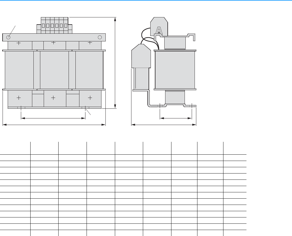
72 PowerXL™ variable frequency drives
Sine filter
CA04020001Z-EN-INT www.eaton.eu
Sine filter
Sine filter
DX-SIN3-004 - DX-SIN3-180
a1
a
b1
b
c
⌀ d2
⌀ d1
aa1bb1cd1d2Weight
mm (inch) mm (inch) mm (inch) mm (inch) mm (inch) kg
DX-SIN3-004 155 (6.1) 130 (5.12) 105 (4.13) 56 (2.2) 160 (6.3) 4 x M5 M4 4.2
DX-SIN3-010 155 (6.1) 130 (5.12) 120 (4.72) 71 (2.8) 160 (6.3) 4 x M5 M4 6.1
DX-SIN3-016 190 (7.48) 170 (6.69) 160 (6.3) 67 (2.64) 185 (7.28) 4 x M5 M4 9.4
DX-SIN3-023 240 (9.45) 190 (7.48) 190 (7.48) 105 (4.13) 280 (11.02) 4 x M6 M6 14.5
DX-SIN3-032 240 (9.45) 190 (7.48) 200 (7.87) 105 (4.13) 280 (11.02) 4 x M6 M6 19.7
DX-SIN3-037 240 (9.45) 190 (7.48) 210 (8.27) 115 (4.53) 280 (11.02) 4 x M6 M6 21.3
DX-SIN3-048 240 (9.45) 190 (7.48) 220 (8.66) 125 (4.92) 280 (11.02) 4 x M6 M6 26.2
DX-SIN3-061 300 (11.81) 240 (9.45) 228 (8.97) 133 (5.24) 315 (12.4) 4 x M8 M8 35
DX-SIN3-072 300 (11.81) 240 (9.45) 240 (9.45) 145 (5.71) 315 (12.4) 4 x M8 M8 39
DX-SIN3-090 300 (11.81) 240 (9.45) 270 (10.63) 171 (6.73) 320 (12.6) 4 x M8 M8 53.3
DX-SIN3-115 360 (14.17) 264 (10.39) 210 (8.27) 125 (4.92) 415 (16.34) 4 x M8 M8 66
DX-SIN3-150 360 (14.17) 264 (10.39) 225 (8.86) 140 (5.51) 415 (16.34) 4 x M10 M8 69
DX-SIN3-180 360 (14.17) 264 (10.39) 240 (9.45) 154 (6.06) 415 (16.34) 4 x M10 M8 88.7
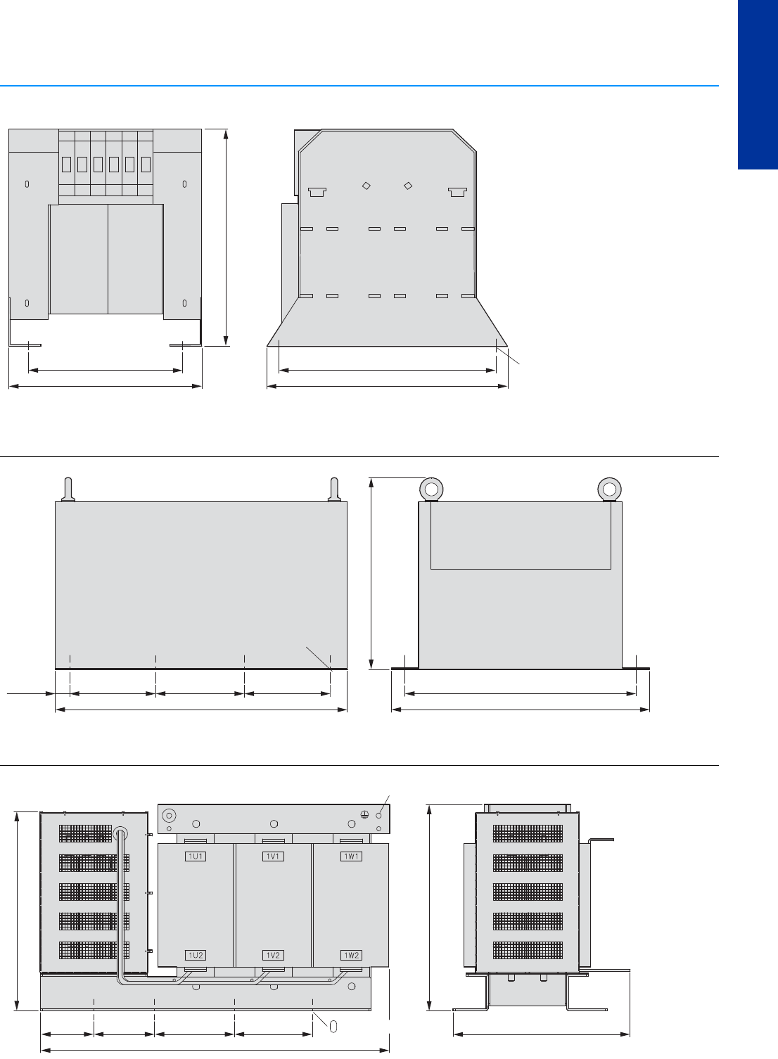
PowerXL™ variable frequency drives
Sine filter
CA04020001Z-EN-INT www.eaton.eu
73
DC1, DA1
Sine filter
Sine filter
DX-SIN3-250
DX-SIN3-440
DX-SIN3-480
≦ 450 mm (≦ 17.7")
≦ 500 mm (≦ 19.7")
≦ 320 mm (≦ 12.6")
≦ 450 mm (≦ 17.7") ± 3 mm (0.1")
≦ 400 mm (≦ 15.7")
⌀ 4 x M10
PE = M12
180 mm (7.1")
610 mm (24") 540 mm (21.3")
480 mm (18.9")
450 mm (17.7") ± 3 mm (0.1")
185 mm (7.3") 180 mm (7.1")32.5 mm
(1.3")
⌀ 6 x M10
PE = M12
≦ 730 mm (≦ 28.7")
110 mm
(4.3")
125 mm
(4.9")
165 mm (6.5") 160 mm (6.3") ≦ 370 mm (≦ 14.6")
425 mm (16.7") ± 3 mm (0.1")
408 mm (16.1") ± 3 mm (0.1")
d1 13 x 26 mm (0.5 x 1")
8 x M10
PE = M12
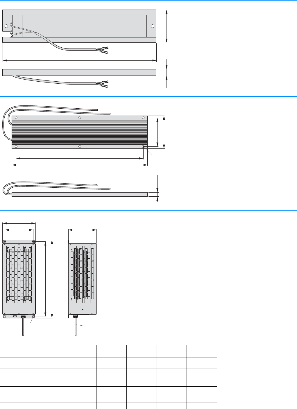
74 PowerXL™ variable frequency drives
Braking resistances DX-BR...
CA04020001Z-EN-INT www.eaton.eu
Braking resistances DX-BR...
DX-BR3-100
DX-BR5-033
DX-BR… with connection cable
41 mm (1.61")
9 mm
(0.35")
188 mm (7.4")
330 mm (12.99")
310 mm (12.2")
80 mm (3.15")
70 mm (2.76")
10 mm
(0.39")
⌀ 5.3 mm
(⌀ 0.21")
b1
a1 c
a
b
6 x 12 1 m
(3.28 ft)
a a1 b b1 c Weight
mm (inch) mm (inch) mm (inch) mm (inch) mm (inch) kg (lbs)
DX-BR200-0K4
DX-BR400-0K4
95 (3.07) 70 (2.76) 445 (17.52) 425 (16.73) 95 (3.07) 2.4 (5.29)
DX-BR150-0K5 140 (5.51) 120 (4.72) 395 (15.55) 375 (14.76) 120 (4.72) 3.7 (8.16)
DX-BR100-0K8
DX-BR200-0K8
140 (5.51) 120 (4.72) 445 (17.52) 425 (16.73) 120 (4.72) 4 (8.82)
DX-BR075-1K4
DX-BR100-1K4
DX-BR150-1K4
230 (9.06) 210 (8.27) 445 (17.52) 425 (16.73) 120 (4.72) 5.7 (12.57)
DX-BR100-1K6 2 x 140 (5.51) 2 x120 (4.72) 445 (17.52) 425 (16.73) 120 (4.72) 2 x 4 (8.82)
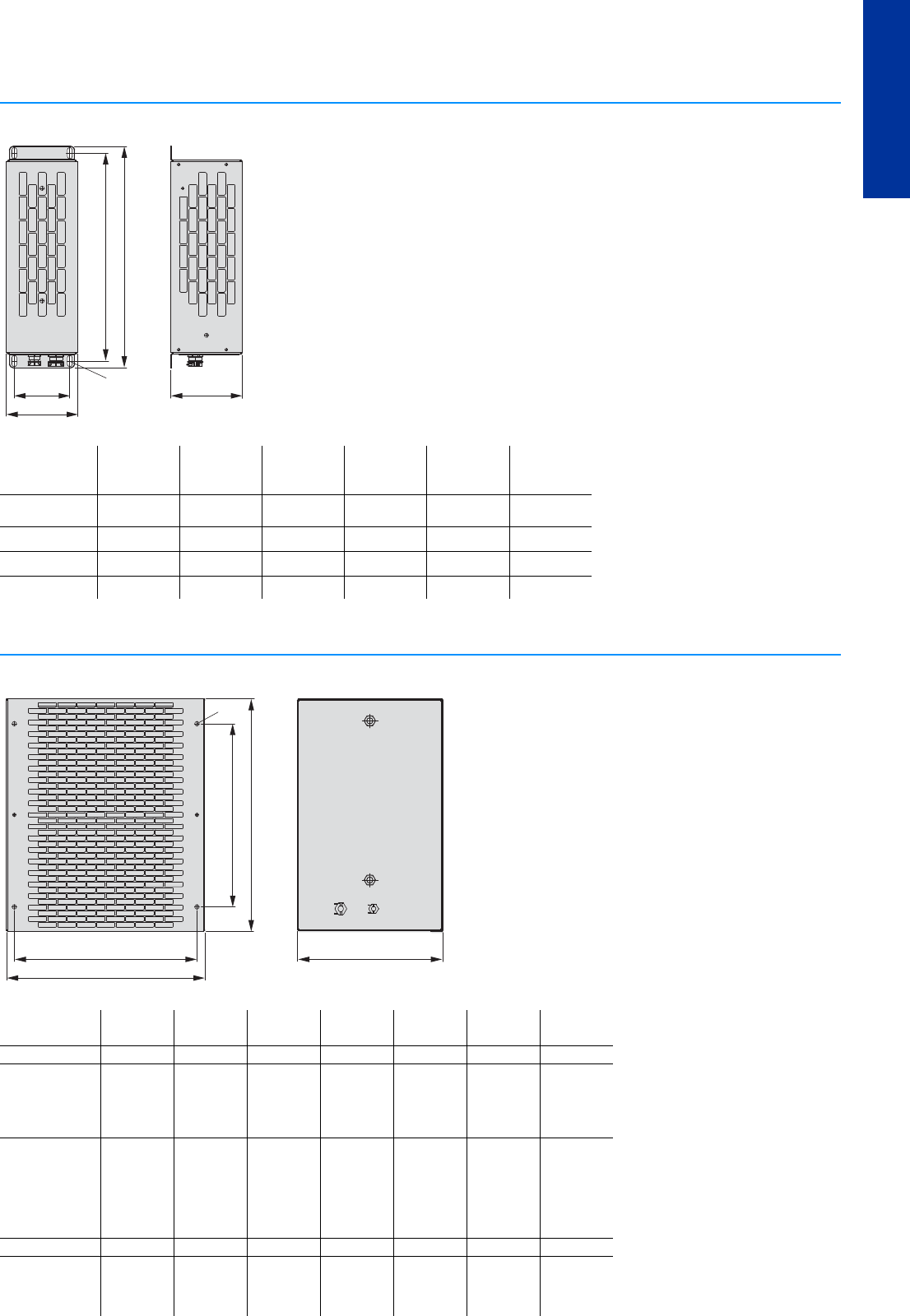
PowerXL™ variable frequency drives
Braking resistances DX-BR...
CA04020001Z-EN-INT www.eaton.eu
75
DC1, DA1
DX-BR… with connection cable
DX-BR… with connection cable
b1
a
a1 c
b
6 x 12
aa1bb1cWeight
mm (inch) mm (inch) mm (inch) mm (inch) mm (inch) kg (lbs)
DX-BR050-0K4
DX-BR100-0K4
95 (3.07) 70 (2.76) 445 (17.52) 425 (16.73) 95 (3.07) 2.1 (4.63)
DX-BR100-0K2 95 (3.07) 70 (2.76) 345 (13.58) 325 (12.8) 95 (3.07) 1.7 (3.75)
DX-BR050-0K8 140 (5.51) 120 (4.72) 445 (17.52) 425 (16.73) 120 (4.72) 4 (8.82)
DX-BR035-1K1 230 (9.06) 210 (8.27) 445 (17.52) 425 (16.73) 120 (4.72) 5.5 (12.13)
a1
a
⌀
b1
b
c
a a1 b b1 c Ø1 Weight
mm (inch) mm (inch) mm (inch) mm (inch) mm (inch) mm (inch) kg (lbs)
DX-BR022-1K4 226 (8.9) 200 (7.87) 485 (19.09) 380 (14.96) 301 (11.85) 9 (0.35) 8.6 (18.96)
DX-BR012-3K1
DX-BR022-3K1
DX-BR040-3K1
DX-BR047-3K1
DX-BR050-3K1
326 (12.83) 300 (11.81) 485 (19.09) 380 (14.96) 301 (11.85) 9 (0.35) 12 (26.46)
DX-BR006-5K1
DX-BR012-5K1
DX-BR022-5K1
DX-BR040-5K1
DX-BR047-5K1
DX-BR050-5K1
DX-BR075-5K1
426 (16.77) 400 (15.75) 485 (19.09) 380 (14.96) 301 (11.85) 9 (0.35) 15.5 (34.17)
DX-BR100-6K2 526 (20.71) 500 (19.69) 485 (19.09) 380 (14.96) 301 (11.85) 9 (0.35) 18 (39.68)
DX-BR006-9K2
DX-BR012-9K2
DX-BR022-9K2
DX-BR047-9K2
626 (24.65) 600 (23.62) 485 (19.09) 380 (14.96) 301 (11.85) 9 (0.35) 20.5 (45.19)

76 PowerXL™ variable frequency drives
Braking resistances DX-BR...
CA04020001Z-EN-INT www.eaton.eu
DX-BR002-54K3, DX-BR006-18K1, DX-BR012-18K1
DX-BR002-102K4, DX-BR006-33K3
600 mm (23.62")
626 mm (24.65")
380 mm (14.96")
485 mm (19.09")
601 mm (23.66")
⌀ 9 mm
(⌀ 0.35")
40 kg
(88.18 lbs)
700 mm (27.56")
736 mm (28.98")
380 mm (14.96")
485 mm (19.09")
1020 mm (40.16")
⌀ 9 mm
(⌀ 0.35")
85 kg
(185.19 lbs)

PowerXL™ variable frequency drives
Notes
CA04020001Z-EN-INT www.eaton.eu
77
DC1, DA1
Notes
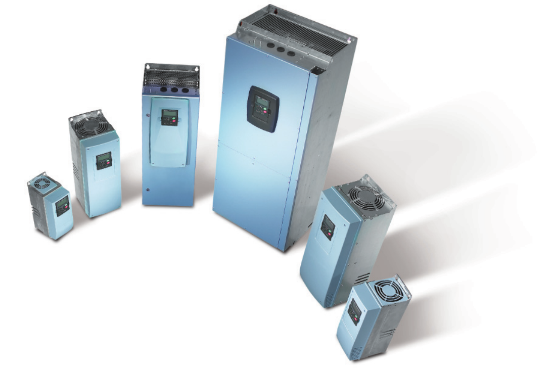
9000X variable frequency drives are ideal for sophisticated applications. With two
different device series, they make a compelling case in a variety of scenarios: SVX stan-
dard variable frequency drives when it comes to simple and complex motor control
systems in industrial machine building environments, and SPX application frequency
drives when it comes to sophisticated, high-performance requirements. In both open-
loop and closed-loop modes, their vector control guarantees reliable, dynamic, and
sophisticated motor control performance when working with three-phase induction or
permanent magnet motors.
SVX variable frequency drive
Variable frequency drives for operation with two overload options: 150% or 110%. The com-
pact enclosures are rated IP21 (NEMA 1) and IP54 (NEMA 12) and come with an integrated
radio interference suppression filter. A braking chopper is integrated into all units up to size
FR6, and, in addition, there are two different models.
SVX…-4A…: UIN 3~400 V/UOUT 3~400 V, allocated motor outputs 0.75 – 132 kW
SVX…-5A…: UIN 3~690 V/UOUT 3~690 V, allocated motor outputs 2.2 – 160 kW
SPX variable frequency drive
Variable frequency drives for operation with two overload options: 150% or 110%. The enclo-
sures for the compact devices are rated IP21 (NEMA 1) and IP54 (NEMA 12) and come with an
integrated radio interference suppression filter. A braking chopper is integrated into all units up
to size FR6, and, in addition, there are two different models.
SPX…-4A…: UIN 3~400 V/UOUT 3~400 V, allocated motor outputs 0.75 – 132 kW1)
SPX…-5A…: UIN 3~690 V/UOUT 3 ~690 V, allocated motor outputs 2.2 – 160 kW1)
1) Higher outputs of up to 1,100 kW (400 V) and 2,000 kW (690 V) are covered by variable frequency drives with
sizes FR10 to FR14. These devices are available upon request from your sales office.
9000X SVX, SPX variable frequency drive

Variable frequency drive 9000X
CA04020001Z-EN-INT www.eaton.eu
79
SVX, SPX
Description
variable frequency drives SVX, SPX 80
Technical overview
variable frequency drives SVX, SPX 81
Key to type references
variable frequency drives SVX, SPX 82
Ordering
variable frequency drives SVX 83
variable frequency drives SPX 88
Accessories 92
Technical data
variable frequency drives SVX, SPX 94
Dimensions
variable frequency drives SVX, SPX 102
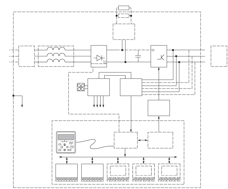
80 Variable frequency drive 9000X
SVX, SPX
CA04020001Z-EN-INT www.eaton.eu
SVX, SPX
Description
SVX, SPX
SVX variable frequency drive SPX variable frequency drive
SVX units are heavy-duty, all-purpose standard variable frequency drives.
Featuring a variety of application settings, they can be configured to meet
virtually any challenge that arises when used to control induction motors,
including applications involving multiple motors or multiple pumps run in
parallel. SVX variable frequency drives are suitable for all standard
applications in machines, buildings, and industrial projects. One of the factors
contributing to this is their sturdy design, which features integrated chokes
and EMC filters and provides effective protection against interference from
the grid. In addition, their sophisticated motor control design and effective
protection features for both motor and variable frequency drive guarantee
reliable operation.
SPX variable frequency drives are the perfect choice when it comes to
demanding applications in which reliability, a highly dynamic response,
precision, and power are a must. Popular applications include lifting
equipment and conveyances (cranes, winches, elevators, lifts), compressors
and oil pumps, chippers, crushers, mixers, extruders, take-up and pay-off
units, and tunnel boring machines. Multi-purpose SPX variable frequency
drives are designed to cover a wide variety of applications while keeping
things simple. In fact, with their excellent flexibility, they make it easy to adapt
to additional process requirements for custom and complex applications used
to control induction and permanent magnet motors. On top of this, their sturdy
design, which features integrated chokes and EMC filters, provides effective
protection against interference from the grid. Finally, their sophisticated motor
control design and effective protection features for both motor and variable
frequency drive guarantee reliable operation.
Essential features Essential features
• Performance range:
– 0.75 - 132 kW (UIN: 3~ 400 V / UOUT: 3~ 400 V)
– 2.2 - 160 kW (UIN: 3~ 690 V / UOUT: 3~ 690 V)
• High load capacity:
– H = 2x rated operational current (2 seconds/20 seconds) and 150%
overload (60 seconds/600 seconds)
– L = 2x rated operational current (2 seconds/20 seconds) and 110%
overload (60 seconds/600 seconds)
• Ambient air temperature: -10 °C up to +50 °C without derating
• Degree of protection with compact design: IP21 (NEMA1) and IP54
(NEMA12)
• I/O expansion with plug-in modules (5 slots)
• Optional fieldbus connection (CANopen, PROFIBUS-DP, DeviceNet),
LonWorks
• PID control and power factor correction (PFC) for 1 to 5 pumps
• Programmable start and application wizard for an easy parameter
configuration process
• Multiple display (multi-monitoring) for monitoring up to 3 different readings
at the same time
• V/Hz control with boost and slip compensation
• Dynamic open-loop and closed-loop vector control
• Internal braking chopper available in sizes of up to FR9 (compact design)
• Performance range:
– 0.75 - 132 kW (UIN: 3~ 400 V / UOUT: 3~ 400 V)
– 2.2 - 160 kW (UIN: 3~ 690 V / UOUT: 3~ 690 V)
• Expanded performance range with distributed design (IP00). Please enquire:
– up to 1100 kW (UIN: 3~ 400 V / UOUT: 3~ 400 V)
– up to 2000 kW (UIN: 3~ 690 V / UOUT: 3~ 690 V)
• High load capacity:
– H = 2x rated operational current (2 seconds/20 seconds) and 150%
overload (60 seconds/600 seconds)
– L = 2x rated operational current (2 seconds/20 seconds) and 110%
overload (60 seconds/600 seconds)
• Ambient air temperature: -10 °C up to +50 °C without derating
• Degree of protection with compact design: Up to 132/160 kW: IP21 (NEMA1)
and IP54 (NEMA12)
• I/O expansion with plug-in modules (5 slots)
• Optional fieldbus connection (CANopen, PROFIBUS-DP, DeviceNet),
LonWorks
• PID control and power factor correction (PFC)
• Direct and parallel circuit solutions, even for PM motors with high outputs
• Programmable start and application wizard for an easy parameter
configuration process
• Multiple display (multi-monitoring) for monitoring up to 3 different readings
at the same time
• V/Hz control with boost and slip compensation
• Dynamic open-loop and closed-loop vector control
• Internal braking chopper available in sizes up to FR9
Charg Res
3~
3~ W
V
U
L3
L2
L1
PE
RS232
Output
Measure-
ments
Motor
IGBT
Inverter Current
Sensors
Voltage
Sensors
Utility
EMC
Rectifier
Brake
Chopper
Brake Resistor
Gate
Drivers
Power
Module
Control
Module
Control
Keypad
Power
Supply
Input
EMC
Fan
AC Choke
Motor
Control
ASIC
Motor and
App lication
Control
Control
I/O
Control
I/O
Control
I/O
Control
I/O
Control
I/O

Variable frequency drive 9000X
SVX, SPX
CA04020001Z-EN-INT www.eaton.eu
81
SVX, SPX
Technical overview
SVX SPX
Rated operational voltage Ue
400 V AC, 3-phase
690 V AC, 3-phase
Mains voltage (50/60Hz) ULN V
380 (-15%) - 500 (+10%)
525 (-15%) - 690 (±10%)
Supply frequency fLN Hz 50/60 50/60
Rated operational current1)
At 110% overload IeA3.3 - 300 3.3 - 300 (2250)2)
At 150% overload IeA2.2 - 245 2.2 - 245 (1940)2)
Assigned motor rating 1)
With 400 V, 50 Hz (110% overload) P kW 1.1 - 160 1.1 - 160 (1200)2)
With 400 V, 50 Hz (150% overload) P kW 0.75 - 132 0.75 - 132 (1100)2)
With 690 V, 60 Hz (110% overload) P kW 3 - 200 3 - 200 (2000)2)
With 690 V, 60 Hz (150% overload) P kW 2.2 - 160 2.2 - 160 (1800)2)
Ambient temperature
Operation °C -10 - +40 -10 - +40
Storage °C -40 - +70 -40 - +70
Operation Mode
U/f control -
sensorless vector control (SLV)
Vector control with feedback (CLV)
Switching frequency fPWM kHz 1 - 16 1 - 16
Output voltage with VeU2
400 V AC, 3-phase
690 V AC, 3-phase
Output Frequency f2Hz 0 - 320 Hz 0 - 320 Hz
Protection type
IP00 - ()2)
IP21
IP54
Fitted with
Radio interference suppression filter
Brake chopper
Analog inputs parameterizable, 2 x (0 - 10 V, 0/4 - 20 mA) parameterizable, 2 x (0 - 10 V, 0/4 - 20 mA)
Analog outputs parameterizable, 1 x (0/4 - 20 mA) parameterizable, 1 x (0/4 - 20 mA)
Digital inputs parameterizable, 6 x (max. 30 V DC) parameterizable, 6 x (max. 30 V DC)
Digital outputs parameterizable, 1 x (48 V DC / 50mA) parameterizable, 1 x (48 V DC / 50mA)
Relay outputs Parameterizable, two N/Os, 8 A (24 VDC) /
8 A (250 VAC) / 0.4 A (125 VDC)
Parameterizable, two N/Os, 8 A (24 VDC) /
8 A (250 VAC) / 0.4 A (125 VDC)
Production quality RoHS, ISO 9001 RoHS, ISO 9001
Standards EMC: EN 61800-3:2004+A1-2012
Safety: EN 61800-5-1: 2003
EMC: EN 61800-3:2004+A1-2012
Safety: EN 61800-5-1: 2003
EMC: EN 61800-3:2004+A1-2012
Safety: EN 61800-5-1: 2003
Certifications CE, cUL, c-Tick CE, cUL, c-Tick
Notes 1)
2)
L = 110% overload for 60 s every 10 min.
H = 150% overload for 60 s every 10 min.
Higher outputs are covered by variable frequency drives with sizes FR10 to FR14. These devices are available as modules with
protection class IP 00 upon request from your sales office.

82 Variable frequency drive 9000X
SVX, SPX
CA04020001Z-EN-INT www.eaton.eu
SVX, SPX
Key to type references
Information relevant for export to North America
Product Standards UL 508C; CSA-C22.2 No. 14; IEC/EN61800-3; IEC/EN61800-5; CE marking
UL File No. E134360
UL Category Control No. NMMS, NMMS2, NMMS7. NMMS8
CSA File No. UL report applies to both US and Canada
CSA Class No. 3211-06
North America Certification UL listed, certified by UL for use in Canada
Specially designed for North
America
No
Suitable for Branch circuits
Max. Voltage Rating
SVX/SPX…-4… 3~ 480 V AC IEC: TN-S UL/CSA: "Y" (Solidly Grounded Wey)
SVX/SPX…-5… 3~ 690 V AC IEC: TN-S UL/CSA: "Y" (Solidly Grounded Wey)
Degree of Protection
SPX…A0… IEC: IP00
SVX/SPX…A1… IEC: IP21
SVX/SPX…A2… IEC: IP54
SVX 007 A 1 - 4 A 1 B 1
0 = IP00/open chassis
1 = IP21/NEMA 1
2 = IP54/NEMA 12
F07 = 0.75 HP = 0.55 kW
001 = 1 HP = 0.75 kW
...
007 = 7.5 HP = 5.5 kW
...
H20 = 2000 HP = 1800 kW
4 = 380 (-15 %) - 500 (+10 %)
5 = 525 (-15 %) - 690 (+10 %)
Assigned motor rating according to
mains voltage category 4, 5
Device series
SVX = Standard frequency drive
SPX = Performance frequency drive
Type
1 = Standard basic device
Brake Chopper
N = no internal brake chopper
B = internal brake chopper
Mains voltage category
Display
A = alpha numeric
Radio interference suppression filters
1 = C2 class in 1
st
and 2
nd
environments
2 = no internal RFI filter
4 = C3 class in 2
nd
environment
AFD software series
A = Standard version
Degree of protection
UL/CSA

Variable frequency drive 9000X
SVX, for three-phase motors 400 V AC
CA04020001Z-EN-INT www.eaton.eu
83
SVX, SPX
SVX, for thr ee-phase motors 400 V AC
Ordering
Rated operational
current1)
Assigned motor
rating 1), 2)
Rated motor current1), 2) Fitted with Frame size Protection
type
Part no.
Article no.
Price
see price
list
Std. pack
L = 110 % H = 150 % L = 110 % H = 150 % L = 110 % H = 150 %
Radio interference
suppression filter
Brake chopper
IeIePPI
eIe
AAkWkW A A
Ue 400 V AC, 3-phase / U2 400 V AC, 3-phase
Mains voltage (50/60Hz) ULN: 380 (-15%) - 500 (+10%) V
3.3 2.2 1.1 0.75 2.6 1.9 FR4 IP21 SVX001A1-4A1B1
125676
1off
IP54 SVX001A2-4A1B1
125677
4.3 3.3 1.5 1.1 3.6 2.6 IP21 SVXF15A1-4A1B1
125707
IP54 SVXF15A2-4A1B1
125708
5.6 4.3 2.2 1.5 5 3.6 IP21 SVX002A1-4A1B1
125748
IP54 SVX002A2-4A1B1
125678
7.6 5.6 3 2.2 6.6 5 IP21 SVX003A1-4A1B1
125679
IP54 SVX003A2-4A1B1
125680
97.6 4 38.56.6 IP21 SVX005A1-4A1B1
125749
IP54 SVX005A2-4A1B1
125753
12 95.54 11.3 8.5 IP21 SVX006A1-4A1B1
125682
IP54 SVX006A2-4A1B1
125683
16 12 7.5 5.5 15.2 11.3 FR5 IP21 SVX007A1-4A1B1
125684
IP54 SVX007A2-4A1B1
125685
23 16 11 7.5 21.7 15.2 IP21 SVX010A1-4A1B1
125686
IP54 SVX010A2-4A1B1
125687
31 23 15 11 29.3 21.7 IP21 SVX015A1-4A1B1
125688
IP54 SVX015A2-4A1B1
125689
38 31 18.5 15 36 29.3 FR6 IP21 SVX020A1-4A1B1
125690
IP54 SVX020A2-4A1B1
125754
46 38 22 18.5 41 36 IP21 SVX025A1-4A1B1
125691
IP54 SVX025A2-4A1B1
125692
61 46 30 22 55 41 IP21 SVX030A1-4A1B1
125693
IP54 SVX030A2-4A1B1
125694
72 61 37 30 68 55 - FR7 IP21 SVX040A1-4A1N1
125695
-IP54SVX040A2-4A1N1
125696
IP21 SVX040A1-4A1B1
132656
IP54 SVX040A2-4A1B1
138452
Notes 1) L = 110% overload for 60 s every 10 min.
H = 150% overload for 60 s every 10 min.
2) Assigned motor rating for normal internally and externally ventilated four-pole, three-phase asynchronous motors with 1500 rpm (at 50 Hz)
or 1800 rpm (at 60 Hz)
Information relevant for export to North America Page 82

84 Variable frequency drive 9000X
SVX, for three-phase motors 400 V AC
CA04020001Z-EN-INT www.eaton.eu
Ue 400 V AC, 3-phase / U2 400 V AC, 3-phase
Mains voltage (50/60Hz) ULN: 380 (-15%) - 500 (+10%) V
87 72 45 37 81 68 FR7 IP21 SVX050A1-4A1B1
138430
1off
-IP54SVX050A2-4A1N1
125697
-IP21SVX050A1-4A1N1
125750
IP54 SVX050A2-4A1B1
138453
105 87 55 45 99 81 -IP54SVX060A2-4A1N1
125698
IP54 SVX060A2-4A1B1
138454
IP21 SVX060A1-4A1B1
138431
-IP21SVX060A1-4A1N1
125751
140 105 75 55 134 99 - FR8 IP21 SVX075A1-4A1N1
125699
-IP54SVX075A2-4A1N1
125700
IP21 SVX075A1-4A1B1
132657
IP54 SVX075A2-4A1B1
138455
170 140 90 75 161 134 -IP21SVX100A1-4A1N1
125701
-IP54SVX100A2-4A1N1
125755
IP21 SVX100A1-4A1B1
132658
IP54 SVX100A2-4A1B1
138456
205 170 110 90 196 161 -IP21SVX125A1-4A1N1
125702
-IP54SVX125A2-4A1N1
125703
IP21 SVX125A1-4A1B1
135242
IP54 SVX125A2-4A1B1
138457
261 205 132 110 231 196 - FR9 IP21 SVX150A1-4A1N1
125704
-IP54SVX150A2-4A1N1
125705
IP54 SVX150A2-4A1B1
138458
IP21 SVX150A1-4A1B1
138432
300 245 160 132 279 231 -IP21SVX200A1-4A1N1
125752
-IP54SVX200A2-4A1N1
125706
IP54 SVX200A2-4A1B1
138459
IP21 SVX200A1-4A1B1
132900
Notes 1) L = 110% overload for 60 s every 10 min.
H = 150% overload for 60 s every 10 min.
2) Assigned motor rating for normal internally and externally ventilated four-pole, three-phase asynchronous motors with 1500 rpm (at 50 Hz)
or 1800 rpm (at 60 Hz)
Information relevant for export to North America Page 82
Rated operational
current1)
Assigned motor
rating 1), 2)
Rated motor current1), 2) Fitted with Frame size Protection
type
Part no.
Article no.
Price
see price
list
Std. pack
L = 110 % H = 150 % L = 110 % H = 150 % L = 110 % H = 150 %
Radio interference
suppression filter
Brake chopper
IeIePPI
eIe
AAkWkW A A

Variable frequency drive 9000X
SVX, for three-phase motors 690 V AC
CA04020001Z-EN-INT www.eaton.eu
85
SVX, SPX
SVX, for thr ee-phase motors 690 V AC
Rated operational
current1)
Assigned motor
rating 1), 2)
Rated motor current1), 2) Fitted with Frame size Protection
type
Part no.
Article no.
Price
see price
list
Std. pack
L = 110 % H = 150 % L = 110 % H = 150 % L = 110 % H = 150 %
Radio interference
suppression filter
Brake chopper
IeIePPI
eIe
AAkWkW A A
Ue 690 V AC, 3-phase / U2 690 V AC, 3-phase
Mains voltage (50/60Hz) ULN: 525 (-15%) - 690 (±10%) V
4.5 3.2 3 2.2 3.8 2.9 - FR6 IP21 SVX002A1-5A4N1
125756
1off
-IP54SVX002A2-5A4N1
125774
IP54 SVX002A2-5A4B1
138498
IP21 SVX002A1-5A4B1
138480
5.5 4.5 4 34.93.8 -IP21SVX003A1-5A4N1
125757
-IP54SVX003A2-5A4N1
125775
IP21 SVX003A1-5A4B1
138481
IP54 SVX003A2-5A4B1
138499
7.5 5.5 5.5 46.54.9 -IP21SVX004A1-5A4N1
125758
-IP54SVX004A2-5A4N1
125776
IP21 SVX004A1-5A4B1
138482
IP54 SVX004A2-5A4B1
138500
10 7.5 7.5 5.5 8.8 6.5 -IP21SVX005A1-5A4N1
125759
-IP54SVX005A2-5A4N1
125777
IP21 SVX005A1-5A4B1
138483
IP54 SVX005A2-5A4B1
138501
13.5 10 11 7.5 12.6 8.8 -IP21SVX007A1-5A4N1
125760
-IP54SVX007A2-5A4N1
125778
IP21 SVX007A1-5A4B1
138484
IP54 SVX007A2-5A4B1
138502
18 13.5 15 11 17 12.6 -IP21SVX010A1-5A4N1
125761
-IP54SVX010A2-5A4N1
125779
IP21 SVX010A1-5A4B1
138485
IP54 SVX010A2-5A4B1
138503
22 18 18.5 15 20.9 17 -IP21SVX015A1-5A4N1
125762
-IP54SVX015A2-5A4N1
125780
IP21 SVX015A1-5A4B1
138486
IP54 SVX015A2-5A4B1
138504
Notes 1) L = 110% overload for 60 s every 10 min.
H = 150% overload for 60 s every 10 min.
2) Assigned motor rating for normal internally and externally ventilated four-pole, three-phase asynchronous motors with 1500 rpm (at 50 Hz)
or 1800 rpm (at 60 Hz)
Information relevant for export to North America Page 82

86 Variable frequency drive 9000X
SVX, for three-phase motors 690 V AC
CA04020001Z-EN-INT www.eaton.eu
Ue 690 V AC, 3-phase / U2 690 V AC, 3-phase
Mains voltage (50/60Hz) ULN: 525 (-15%) - 690 (±10%) V
27 22 22 18.5 23.8 20.9 - FR6 IP21 SVX020A1-5A4N1
125763
1off
-IP54SVX020A2-5A4N1
125781
IP21 SVX020A1-5A4B1
138487
IP54 SVX020A2-5A4B1
138505
34 27 30 22 32 23.8 -IP21SVX025A1-5A4N1
125764
-IP54SVX025A2-5A4N1
125782
IP21 SVX025A1-5A4B1
138488
IP54 SVX025A2-5A4B1
138506
41 34 37 30 39 32 - FR7 IP21 SVX030A1-5A4N1
125765
-IP54SVX030A2-5A4N1
125783
IP21 SVX030A1-5A4B1
138489
IP54 SVX030A2-5A4B1
138507
52 41 45 37 47 39 -IP54SVX040A2-5A4N1
125784
-IP21SVX040A1-5A4N1
125766
IP21 SVX040A1-5A4B1
138490
IP54 SVX040A2-5A4B1
138508
62 52 55 45 58 47 - FR8 IP21 SVX050A1-5A4N1
125767
-IP54SVX050A2-5A4N1
125785
IP54 SVX050A2-5A4B1
138509
IP21 SVX050A1-5A4B1
138491
80 62 75 55 78 58 -IP21SVX060A1-5A4N1
125768
-IP54SVX060A2-5A4N1
125786
IP21 SVX060A1-5A4B1
138492
IP54 SVX060A2-5A4B1
138510
100 80 90 75 93 78 -IP21SVX075A1-5A4N1
125769
-IP54SVX075A2-5A4N1
125787
IP21 SVX075A1-5A4B1
138493
IP54 SVX075A2-5A4B1
138511
Notes 1) L = 110% overload for 60 s every 10 min.
H = 150% overload for 60 s every 10 min.
2) Assigned motor rating for normal internally and externally ventilated four-pole, three-phase asynchronous motors with 1500 rpm (at 50 Hz)
or 1800 rpm (at 60 Hz)
Information relevant for export to North America Page 82
Rated operational
current1)
Assigned motor
rating 1), 2)
Rated motor current1), 2) Fitted with Frame size Protection
type
Part no.
Article no.
Price
see price
list
Std. pack
L = 110 % H = 150 % L = 110 % H = 150 % L = 110 % H = 150 %
Radio interference
suppression filter
Brake chopper
IeIePPI
eIe
AAkWkW A A

Variable frequency drive 9000X
SVX, for three-phase motors 690 V AC
CA04020001Z-EN-INT www.eaton.eu
87
SVX, SPX
Ue 690 V AC, 3-phase / U2 690 V AC, 3-phase
Mains voltage (50/60Hz) ULN: 525 (-15%) - 690 (±10%) V
125 100 110 90 114 93 - FR9 IP21 SVX100A1-5A4N1
125770
1off
-IP54SVX100A2-5A4N1
125788
IP21 SVX100A1-5A4B1
138494
IP54 SVX100A2-5A4B1
138512
144 125 132 110 134 114 -IP21SVX125A1-5A4N1
125771
-IP54SVX125A2-5A4N1
125789
IP54 SVX125A2-5A4B1
138513
IP21 SVX125A1-5A4B1
138495
170 144 160 132 162 134 -IP21SVX150A1-5A4N1
125772
-IP54SVX150A2-5A4N1
125790
IP21 SVX150A1-5A4B1
138496
IP54 SVX150A2-5A4B1
138514
208 170 200 160 202 162 -IP21SVX175A1-5A4N1
125773
-IP54SVX175A2-5A4N1
125791
IP21 SVX175A1-5A4B1
138497
IP54 SVX175A2-5A4B1
138515
Notes 1) L = 110% overload for 60 s every 10 min.
H = 150% overload for 60 s every 10 min.
2) Assigned motor rating for normal internally and externally ventilated four-pole, three-phase asynchronous motors with 1500 rpm (at 50 Hz)
or 1800 rpm (at 60 Hz)
Information relevant for export to North America Page 82
Rated operational
current1)
Assigned motor
rating 1), 2)
Rated motor current1), 2) Fitted with Frame size Protection
type
Part no.
Article no.
Price
see price
list
Std. pack
L = 110 % H = 150 % L = 110 % H = 150 % L = 110 % H = 150 %
Radio interference
suppression filter
Brake chopper
IeIePPI
eIe
AAkWkW A A

88 Variable frequency drive 9000X
SPX, for three-phase motors 400 V AC
CA04020001Z-EN-INT www.eaton.eu
SPX, for thr ee-phase motors 400 V AC
Rated operational
current1)
Assigned motor
rating 1), 2)
Rated motor current1), 2) Fitted with Frame size Protection
type
Part no.
Article no.
Price
see price
list
Std. pack
L = 110 % H = 150 % L = 110 % H = 150 % L = 110 % H = 150 %
Radio interference
suppression filter
Brake chopper
IeIePPI
eIe
AAkWkW A A
Ue 400 V AC, 3-phase / U2 400 V AC, 3-phase
Mains voltage (50/60Hz) ULN: 380 (-15%) - 500 (+10%) V
3.3 2.2 1.1 0.75 2.6 1.9 FR4 IP21 SPX001A1-4A1B1
125203
1off
IP54 SPX001A2-4A1B1
125207
4.3 3.3 1.5 1.1 3.6 2.6 IP21 SPXF15A1-4A1B1
125675
IP54 SPXF15A2-4A1B1
125480
5.6 4.3 2.2 1.5 5 3.6 IP21 SPX002A1-4A1B1
125657
IP54 SPX002A2-4A1B1
125216
7.6 5.6 3 2.2 6.6 5 IP21 SPX003A1-4A1B1
125658
IP54 SPX003A2-4A1B1
125226
97.6 4 38.56.6 IP21 SPX005A1-4A1B1
125659
IP54 SPX005A2-4A1B1
125245
12 95.54 11.3 8.5 IP21 SPX006A1-4A1B1
125249
IP54 SPX006A2-4A1B1
125251
16 12 7.5 5.5 15.2 11.3 FR5 IP21 SPX007A1-4A1B1
125660
IP54 SPX007A2-4A1B1
125260
23 16 11 7.5 21.7 15.2 IP21 SPX010A1-4A1B1
125661
IP54 SPX010A2-4A1B1
125662
31 23 15 11 29.3 21.7 IP21 SPX015A1-4A1B1
125663
IP54 SPX015A2-4A1B1
125664
38 31 18.5 15 36 29.3 FR6 IP21 SPX020A1-4A1B1
125665
IP54 SPX020A2-4A1B1
125291
46 38 22 18.5 41 36 IP21 SPX025A1-4A1B1
125666
IP54 SPX025A2-4A1B1
125302
61 46 30 22 55 41 IP21 SPX030A1-4A1B1
125667
IP54 SPX030A2-4A1B1
125313
72 61 37 30 68 55 - FR7 IP21 SPX040A1-4A1N1
125319
-IP54SPX040A2-4A1N1
125325
IP21 SPX040A1-4A1B1
134844
IP54 SPX040A2-4A1B1
138609
Notes 1) L = 110% overload for 60 s every 10 min.
H = 150% overload for 60 s every 10 min.
2) Assigned motor rating for normal internally and externally ventilated four-pole, three-phase asynchronous motors with 1500 rpm (at 50 Hz)
or 1800 rpm (at 60 Hz)
Information relevant for export to North America Page 82

Variable frequency drive 9000X
SPX, for three-phase motors 400 V AC
CA04020001Z-EN-INT www.eaton.eu
89
SVX, SPX
Ue 400 V AC, 3-phase / U2 400 V AC, 3-phase
Mains voltage (50/60Hz) ULN: 380 (-15%) - 500 (+10%) V
87 72 45 37 81 68 - FR7 IP21 SPX050A1-4A1N1
125331
1off
-IP54SPX050A2-4A1N1
125337
IP21 SPX050A1-4A1B1
138606
IP54 SPX050A2-4A1B1
138610
105 87 55 45 99 81 -IP21SPX060A1-4A1N1
125668
-IP54SPX060A2-4A1N1
125348
IP21 SPX060A1-4A1B1
138607
IP54 SPX060A2-4A1B1
138611
140 105 75 55 134 99 - FR8 IP21 SPX075A1-4A1N1
125354
-IP54SPX075A2-4A1N1
125359
IP21 SPX075A1-4A1B1
138608
IP54 SPX075A2-4A1B1
138612
170 140 90 75 161 134 -IP21SPX100A1-4A1N1
125365
-IP54SPX100A2-4A1N1
125370
IP21 SPX100A1-4A1B1
131744
IP54 SPX100A2-4A1B1
138613
205 170 110 90 196 161 -IP21SPX125A1-4A1N1
125669
-IP54SPX125A2-4A1N1
125377
IP21 SPX125A1-4A1B1
134489
IP54 SPX125A2-4A1B1
138614
261 205 132 110 231 196 - FR9 IP21 SPX150A1-4A1N1
125381
-IP54SPX150A2-4A1N1
125385
IP21 SPX150A1-4A1B1
129701
IP54 SPX150A2-4A1B1
138615
300 245 160 132 279 231 -IP21SPX200A1-4A1N1
125670
-IP54SPX200A2-4A1N1
125398
IP21 SPX200A1-4A1B1
134845
IP54 SPX200A2-4A1B1
138616
Notes 1) L = 110% overload for 60 s every 10 min.
H = 150% overload for 60 s every 10 min.
2) Assigned motor rating for normal internally and externally ventilated four-pole, three-phase asynchronous motors with 1500 rpm (at 50 Hz)
or 1800 rpm (at 60 Hz)
Information relevant for export to North America Page 82
Rated operational
current1)
Assigned motor
rating 1), 2)
Rated motor current1), 2) Fitted with Frame size Protection
type
Part no.
Article no.
Price
see price
list
Std. pack
L = 110 % H = 150 % L = 110 % H = 150 % L = 110 % H = 150 %
Radio interference
suppression filter
Brake chopper
IeIePPI
eIe
AAkWkW A A

90 Variable frequency drive 9000X
SPX, for three-phase motors 690 V AC
CA04020001Z-EN-INT www.eaton.eu
SPX, for thr ee-phase motors 690 V AC
Rated operational
current1)
Assigned motor
rating 1), 2)
Rated motor current1), 2) Fitted with Frame size Protection
type
Part no.
Article no.
Price
see price
list
Std. pack
L = 110 % H = 150 % L = 110 % H = 150 % L = 110 % H = 150 %
Radio interference
suppression filter
Brake chopper
IeIePPI
eIe
AAkWkW A A
Ue 690 V AC, 3-phase / U2 690 V AC, 3-phase
Mains voltage (50/60Hz) ULN: 525 (-15%) - 690 (±10%) V
4.5 3.2 3 2.2 3.8 2.9 - FR6 IP21 SPX002A1-5A4N1
125212
1off
-IP54SPX002A2-5A4N1
125218
IP21 SPX002A1-5A4B1
138638
IP54 SPX002A2-5A4B1
129582
5.5 4.5 4 34.93.8 -IP54SPX003A2-5A4N1
125228
-IP21SPX003A1-5A4N1
125222
IP21 SPX003A1-5A4B1
138639
IP54 SPX003A2-5A4B1
129583
7.5 5.5 5.5 46.54.9 -IP21SPX004A1-5A4N1
125232
IP54 SPX004A2-5A4B1
129584
IP21 SPX004A1-5A4B1
138640
-IP54SPX004A2-5A4N1
125236
10 7.5 7.5 5.5 8.8 6.5 -IP21SPX005A1-5A4N1
125241
-IP54SPX005A2-5A4N1
125247
IP21 SPX005A1-5A4B1
138641
IP54 SPX005A2-5A4B1
129585
13.5 10 11 7.5 12.6 8.8 -IP21SPX007A1-5A4N1
125256
-IP54SPX007A2-5A4N1
125262
IP21 SPX007A1-5A4B1
138642
IP54 SPX007A2-5A4B1
129586
18 13.5 15 11 17 12.6 -IP21SPX010A1-5A4N1
125267
-IP54SPX010A2-5A4N1
125272
IP21 SPX010A1-5A4B1
138643
IP54 SPX010A2-5A4B1
129587
22 18 18.5 15 20.9 17 -IP21SPX015A1-5A4N1
125277
-IP54SPX015A2-5A4N1
125282
IP21 SPX015A1-5A4B1
138644
IP54 SPX015A2-5A4B1
129588
Notes 1) L = 110% overload for 60 s every 10 min.
H = 150% overload for 60 s every 10 min.
2) Assigned motor rating for normal internally and externally ventilated four-pole, three-phase asynchronous motors with 1500 rpm (at 50 Hz)
or 1800 rpm (at 60 Hz)
Information relevant for export to North America Page 82

Variable frequency drive 9000X
SPX, for three-phase motors 690 V AC
CA04020001Z-EN-INT www.eaton.eu
91
SVX, SPX
Ue 690 V AC, 3-phase / U2 690 V AC, 3-phase
Mains voltage (50/60Hz) ULN: 525 (-15%) - 690 (±10%) V
27 22 22 18.5 23.8 20.9 - FR6 IP21 SPX020A1-5A4N1
125287
1off
-IP54SPX020A2-5A4N1
125293
IP21 SPX020A1-5A4B1
138645
IP54 SPX020A2-5A4B1
129589
34 27 30 22 32 23.8 -IP21SPX025A1-5A4N1
125298
-IP54SPX025A2-5A4N1
125304
IP54 SPX025A2-5A4B1
129590
IP21 SPX025A1-5A4B1
138646
41 34 37 30 39 32 - FR7 IP21 SPX030A1-5A4N1
125309
-IP54SPX030A2-5A4N1
125315
IP21 SPX030A1-5A4B1
138647
IP54 SPX030A2-5A4B1
129591
52 41 45 37 47 39 -IP21SPX040A1-5A4N1
125321
-IP54SPX040A2-5A4N1
125327
IP21 SPX040A1-5A4B1
138648
IP54 SPX040A2-5A4B1
129592
62 52 55 45 58 47 - FR8 IP21 SPX050A1-5A4N1
125333
-IP54SPX050A2-5A4N1
125339
IP21 SPX050A1-5A4B1
138649
IP54 SPX050A2-5A4B1
129593
80 62 75 55 78 58 -IP21SPX060A1-5A4N1
125344
-IP54SPX060A2-5A4N1
125350
IP21 SPX060A1-5A4B1
138650
IP54 SPX060A2-5A4B1
129594
100 80 90 75 93 78 -IP21SPX075A1-5A4N1
125356
-IP54SPX075A2-5A4N1
125361
IP54 SPX075A2-5A4B1
129595
IP21 SPX075A1-5A4B1
138651
Notes 1) L = 110% overload for 60 s every 10 min.
H = 150% overload for 60 s every 10 min.
2) Assigned motor rating for normal internally and externally ventilated four-pole, three-phase asynchronous motors with 1500 rpm (at 50 Hz)
or 1800 rpm (at 60 Hz)
Information relevant for export to North America Page 82
Rated operational
current1)
Assigned motor
rating 1), 2)
Rated motor current1), 2) Fitted with Frame size Protection
type
Part no.
Article no.
Price
see price
list
Std. pack
L = 110 % H = 150 % L = 110 % H = 150 % L = 110 % H = 150 %
Radio interference
suppression filter
Brake chopper
IeIePPI
eIe
AAkWkW A A

92 Variable frequency drive 9000X
SPX, for three-phase motors 690 V AC, Accessories
CA04020001Z-EN-INT www.eaton.eu
SPX, for three-phase m otors 690 V AC, Accessories
Accessories
Ue 690 V AC, 3-phase / U2 690 V AC, 3-phase
Mains voltage (50/60Hz) ULN: 525 (-15%) - 690 (±10%) V
125 100 110 90 114 93 - FR9 IP21 SPX100A1-5A4N1
125367
1off
-IP54SPX100A2-5A4N1
125372
IP21 SPX100A1-5A4B1
138652
IP54 SPX100A2-5A4B1
129596
144 125 132 110 134 114 -IP21SPX125A1-5A4N1
125375
-IP54SPX125A2-5A4N1
125379
IP21 SPX125A1-5A4B1
138653
IP54 SPX125A2-5A4B1
129597
170 144 160 132 162 134 - FR9 IP21 SPX150A1-5A4N1
125383
1off
-IP54SPX150A2-5A4N1
125387
IP21 SPX150A1-5A4B1
138654
IP54 SPX150A2-5A4B1
129598
208 170 200 160 202 162 -IP21SPX175A1-5A4N1
125389
-IP54SPX175A2-5A4N1
125391
IP21 SPX175A1-5A4B1
138655
IP54 SPX175A2-5A4B1
129599
Notes 1) L = 110% overload for 60 s every 10 min.
H = 150% overload for 60 s every 10 min.
2) Assigned motor rating for normal internally and externally ventilated four-pole, three-phase asynchronous motors with 1500 rpm (at 50 Hz)
or 1800 rpm (at 60 Hz)
Information relevant for export to North America Page 82
Description For use with Part no.
Article no.
Price
see price
list
Std. pack Information relevant for export to North
America
External keypad
With illuminated LCD display
Plain text, multi-line
With control buttons and
function keys
Front IP54
SVX, SPX KEYPAD-LOC/REM
139787
1off Product Standards UL 508C; CSA-C22.2
No. 14; IEC/EN61800-3;
IEC/EN61800-5; CE
marking
UL File No. E134360
UL Category
Control No. NMMS, NMMS2,
NMMS7. NMMS8
CSA File No. UL report applies to
both US and Canada
CSA Class No. 3211-06
North America
Certification UL listed, certified by
UL for use in Canada
Suitable for Branch circuits
Mounting unit
Mounting frame for control
panel door 3 m
KEYPAD-
LOC/REM
OPTRMT-KIT
126868
1off
Connection cable
Connection between variable
frequency drive and PC 1.5 m
SVX, SPX SVDRIVECABLE
129001
1off
Rated operational
current1)
Assigned motor
rating 1), 2)
Rated motor current1), 2) Fitted with Frame size Protection
type
Part no.
Article no.
Price
see price
list
Std. pack
L = 110 % H = 150 % L = 110 % H = 150 % L = 110 % H = 150 %
Radio interference
suppression filter
Brake chopper
IeIePPI
eIe
AAkWkW A A

Variable frequency drive 9000X
Accessories
CA04020001Z-EN-INT www.eaton.eu
93
SVX, SPX
Accessories
Description For use
with
Part no.
Article no.
Price
see price
list
Std. pack Information relevant for export to North
America
Expansion modules
The expansion module is plugged into the variable-frequency drive.
Adapters Product Standards UL 508C; CSA-C22.2
No. 14; IEC/EN61800-3;
IEC/EN61800-5; CE
marking
UL File No. E134360
UL Category
Control No. NMMS, NMMS2,
NMMS7. NMMS8
CSA File No. UL report applies to
both US and Canada
CSA Class No. 3211-06
North America
Certification UL listed, certified by
UL for use in Canada
Suitable for Branch circuits
System bus adapter SPX OPTD1
125077
1off
System bus adapter with
CANopen® interface
SPX OPTD2
125078
RS232 adapter SPX OPTD3
125079
Output expansion
1 relay output (NO/NC)
1 relay output (NC)
1 Thermistor input
SPX OPTA3
125050
1off
2 relay outputs (NO/NC) SVX, SPX OPTA2
125049
1 relay output (NO)
5 digital inputs (42 - 240 V AC)
SVX, SPX OPTB9
125064
3 relay outputs (NO) SVX, SPX OPTB5
125062
1 relay output (NO/NC)
1 relay output (NO)
1 Thermistor input
SVX, SPX OPTB2
125060
I/O expansion
6 digital inputs
External 24 V supply
SVX, SPX OPTB1
125059
1off
6 digital inputs
1 digital output
2 analog inputs (mA/V)
1 analog output
SVX, SPX OPTA9
125055
3 digital inputs
1 relay output (NO/NC)
1 digital output
SVX, SPX OPTAA
125056
6 digital inputs
1 digital output
2 analog inputs (mA/V)
1 analog output
SPX OPTA8
125054
1 analog input (mA, isolated)
2 analog outputs (mA, isolated)
SVX, SPX OPTB4
125061
Encoder module
HTL (+15 V/24 V)
Master / Slave capability
SPX OPTA7
125053
1off
Temperature sensor expansion
3 Pt100
External 24 V supply
SVX, SPX OPTB8
125063
1off
Fieldbus modules
The field bus module is plugged into the variable-frequency drive.
Modbus RS485
Screw terminals
SVX, SPX OPTC2
125067
1off
PROFIBUS-DP
Screw terminals
SVX, SPX OPTC3
125068
LonWorks
Screw terminals
SVX, SPX OPTC4
125069
CANopen®
Screw terminals
SVX, SPX OPTC6
125710
PROFIBUS-DP
SUB-D 9 pole, socket
SVX, SPX OPTC5
125070
DeviceNet
SUB-D 9 pole, socket
SVX, SPX OPTC7
125071
Modbus RS485
SUB-D 9 pole, socket
SVX, SPX OPTC8
125072
Modbus-TCP
RJ45, 8-pole
SVX, SPX OPTCI
125075
BACnet/IP
RJ45, 8-pole
SVX, SPX OPTCJ
125076

94 Variable frequency drive 9000X
SVX, SPX (Ue: 400 V AC, 3-phase/U2: 400 V AC, 3-phase
CA04020001Z-EN-INT www.eaton.eu CA04020001Z-EN-INT www.eaton.eu
Variable frequency drive 9000X
SVX, SPX (Ue: 400 V AC, 3-phase/U2: 400 V AC, 3-phase
SVX, SPX
SVX, SPX (Ue: 400 V AC, 3-phase/U2: 400 V AC, 3-phase
Technical data
SVX001…
SPX001…
SVXF15…
SPXF15…
SVX002…
SPX002…
SVX003…
SPX003…
SVX005…
SPX005…
SVX006…
SPX006…
SVX007…
SPX007…
SVX010…
SPX010…
SVX015…
SPX015…
SVX020…
SPX020…
General
Standards EMC: EN 61800-3:2004+A1-2012
Safety: EN 61800-5-1: 2003
EMC: EN 61800-3:2004+A1-2012
Safety: EN 61800-5-1: 2003
Certifications CE, cUL, c-Tick CE, cUL, c-Tick CE, cUL, c-Tick CE, cUL, c-Tick CE, cUL, c-Tick CE, cUL, c-Tick CE, cUL, c-Tick CE, cUL, c-Tick CE, cUL, c-Tick CE, cUL, c-Tick
Production quality RoHS, ISO 9001 RoHS, ISO 9001 RoHS, ISO 9001 RoHS, ISO 9001 RoHS, ISO 9001 RoHS, ISO 9001 RoHS, ISO 9001 RoHS, ISO 9001 RoHS, ISO 9001 RoHS, ISO 9001
Climatic proofing w%< 95% relative humidity, no condensation, no corrosion, no dripping water < 95% relative humidity, no condensation, no corrosion, no dripping water
Ambient temperature
Operation °C -10 - +40 -10 - +40 -10 - +40 -10 - +40 -10 - +40 -10 - +40 -10 - +40 -10 - +40 -10 - +40 -10 - +40
Storage °C -40 - +70 -40 - +70 -40 - +70 -40 - +70 -40 - +70 -40 - +70 -40 - +70 -40 - +70 -40 - +70 -40 - +70
Radio interference level
Radio interference class (EMC) C2, C3, depending on the motor cable length, the connected load, and ambient conditions. External radio
interference suppression filters (optional) may be necessary.
C2, C3, depending on the motor cable length, the connected load, and ambient conditions. External radio interference suppression filters (optional) may be necessary.
Environment (EMC) 1st and 2nd
environments
1st and 2nd
environments
1st and 2nd
environments
1st and 2nd
environments
1st and 2nd environments 1st and 2nd environments 1st and 2nd environments 1st and 2nd environments 1st and 2nd environments 1st and 2nd environments
Mounting position Vertical Vertical Vertical Vertical Vertical Vertical Vertical Vertical Vertical Vertical
Altitude m 0 - 1000 m above sea level
above 1000m with 1 % performance reduction per 100m
max. 3000 m
0 - 1000 m above sea level
above 1000m with 1 % performance reduction per 100m
max. 3000 m
Protection against direct contact BGV A3 (VBG4, finger- and back-of-hand proof) BGV A3 (VBG4, finger- and back-of-hand proof)
Weight kg 5 5 5 5 5 5 8.1 8.1 8.1 18.5
Main circuit
Supply
Rated operational voltage UeV400 V AC, 3-phase 400 V AC, 3-phase 400 V AC, 3-phase 400 V AC, 3-phase 400 V AC, 3-phase 400 V AC, 3-phase 400 V AC, 3-phase 400 V AC, 3-phase 400 V AC, 3-phase 400 V AC, 3-phase
Mains voltage (50/60Hz) ULN V380 (-15%) - 500 (+10%) 380 (-15%) - 500 (+10%) 380 (-15%) - 500 (+10%) 380 (-15%) - 500 (+10%) 380 (-15%) - 500 (+10%) 380 (-15%) - 500 (+10%) 380 (-15%) - 500 (+10%) 380 (-15%) - 500 (+10%) 380 (-15%) - 500 (+10%) 380 (-15%) - 500 (+10%)
Supply frequency fLN Hz 50/60 50/60 50/60 50/60 50/60 50/60 50/60 50/60 50/60 50/60
Frequency range fLN Hz 45 - 66 Hz 45 - 66 Hz 45 - 66 Hz 45 - 66 Hz 45 - 66 Hz 45 - 66 Hz 45 - 66 Hz 45 - 66 Hz 45 - 66 Hz 45 - 66 Hz
Power section
Function Frequency inverter with internal DC link and IGBT inverter Frequency inverter with internal DC link and IGBT inverter
Output voltage with VeU2V400 V AC, 3-phase 400 V AC, 3-phase 400 V AC, 3-phase 400 V AC, 3-phase 400 V AC, 3-phase 400 V AC, 3-phase 400 V AC, 3-phase 400 V AC, 3-phase 400 V AC, 3-phase 400 V AC, 3-phase
Output Frequency f2Hz 0 - 320 Hz 0 - 320 Hz 0 - 320 Hz 0 - 320 Hz 0 - 320 Hz 0 - 320 Hz 0 - 320 Hz 0 - 320 Hz 0 - 320 Hz 0 - 320 Hz
Switching frequency fPWM kHz 10
(adjustable 1 - 16)
10
(adjustable 1 - 16)
10
(adjustable 1 - 16)
10
(adjustable 1 - 16)
10
(adjustable 1 - 16)
10
(adjustable 1 - 16)
10
(adjustable 1 - 16)
10
(adjustable 1 - 16)
10
(adjustable 1 - 16)
10
(adjustable 1 - 16)
Operation Mode
SVX… U/f control
sensorless vector control (SLV)
U/f control
sensorless vector control (SLV)
SPX… U/f control
sensorless vector control (SLV)
Vector control with feedback (CLV)
U/f control
sensorless vector control (SLV)
Vector control with feedback (CLV)
Frequency resolution (setpoint value) fHz 0.01 0.01 0.01 0.01 0.01 0.01 0.01 0.01 0.01 0.01
Rated operational current
At 110% overload IeA3.3 4.3 5.6 7.6 912 16 23 31 38
At 150% overload IeA2.2 3.3 4.3 5.6 7.6 912 16 23 31
Motor feeder
Assigned motor rating
Note For AC motors with internal and external ventilation with 50 Hz / 60 Hz For AC motors with internal and external ventilation with 50 Hz / 60 Hz
With 400 V, 50 Hz (110% overload) P kW 1.1 1.5 2.2 3 4 5.5 7.5 11 15 18.5
With 400 V, 50 Hz (150% overload) P kW 0.75 1.1 1.5 2.2 3 4 5.5 7.5 11 15
With 440 - 480 V, 60 Hz (110% overload) P HP 1.5 2 3 5 6 7.5 10 15 20 25
With 440 - 480 V, 60 Hz (150% overload) P HP 11.5 2 3 5 6 7.5 10 15 20
Control section
External control voltage UcV24 V DC (max. 250 mA) 24 V DC (max. 250 mA) 24 V DC (max. 250 mA) 24 V DC (max. 250 mA) 24 V DC (max. 250 mA) 24 V DC (max. 250 mA) 24 V DC (max. 250 mA) 24 V DC (max. 250 mA) 24 V DC (max. 250 mA) 24 V DC (max. 250 mA)
Reference voltage UsV10 V DC (max. 10 mA) 10 V DC (max. 10 mA) 10 V DC (max. 10 mA) 10 V DC (max. 10 mA) 10 V DC (max. 10 mA) 10 V DC (max. 10 mA) 10 V DC (max. 10 mA) 10 V DC (max. 10 mA) 10 V DC (max. 10 mA) 10 V DC (max. 10 mA)
95
SVX, SPX (Ue: 400 V AC, 3-phase, U2: 400 V AC, 3-phase SVX, SPX (Ue: 400 V AC, 3-phase, U2: 400 V AC, 3-phase)

96 Variable frequency drive 9000X
SVX, SPX (Ue: 400 V AC, 3-phase/U2: 400 V AC, 3-phase
CA04020001Z-EN-INT www.eaton.eu CA04020001Z-EN-INT www.eaton.eu
Variable frequency drive 9000X
SVX, SPX (Ue: 400 V AC, 3-phase/U2: 400 V AC, 3-phase
SVX, SPX
SVX025…
SPX025…
SVX030…
SPX030…
SVX040…
SPX040…
SVX050…
SPX050…
SVX060…
SPX060…
SVX075…
SPX075…
SVX100…
SPX100…
SVX125…
SPX125…
SVX150…
SPX150…
SVX200…
SPX200…
General
Standards EMC: EN 61800-3:2004+A1-2012
Safety: EN 61800-5-1: 2003
EMC: EN 61800-3:2004+A1-2012
Safety: EN 61800-5-1: 2003
Certifications CE, cUL, c-Tick CE, cUL, c-Tick CE, cUL, c-Tick CE, cUL, c-Tick CE, cUL, c-Tick CE, cUL, c-Tick CE, cUL, c-Tick CE, cUL, c-Tick CE, cUL, c-Tick CE, cUL, c-Tick
Production quality RoHS, ISO 9001 RoHS, ISO 9001 RoHS, ISO 9001 RoHS, ISO 9001 RoHS, ISO 9001 RoHS, ISO 9001 RoHS, ISO 9001 RoHS, ISO 9001 RoHS, ISO 9001 RoHS, ISO 9001
Climatic proofing w%< 95% relative humidity, no condensation, no corrosion, no dripping water < 95% relative humidity, no condensation, no corrosion, no dripping water
Ambient temperature
Operation °C -10 - +40 -10 - +40 -10 - +40 -10 - +40 -10 - +40 -10 - +40 -10 - +40 -10 - +40 -10 - +40 -10 - +40
Storage °C -40 - +70 -40 - +70 -40 - +70 -40 - +70 -40 - +70 -40 - +70 -40 - +70 -40 - +70 -40 - +70 -40 - +70
Radio interference level
Radio interference class (EMC) C2, C3, depending on the motor cable length, the connected load, and ambient conditions. External radio
interference suppression filters (optional) may be necessary.
C2, C3, depending on the motor cable length, the connected load, and ambient conditions. External radio interference suppression filters (optional) may be necessary.
Environment (EMC) 1st and 2nd
environments
1st and 2nd
environments
1st and 2nd
environments
1st and 2nd
environments
1st and 2nd environments 1st and 2nd environments 1st and 2nd environments 1st and 2nd environments 1st and 2nd environments 1st and 2nd environments
Mounting position Vertical Vertical Vertical Vertical Vertical Vertical Vertical Vertical Vertical Vertical
Altitude m 0 - 1000 m above sea level
above 1000m with 1 % performance reduction per 100m
max. 3000 m
0 - 1000 m above sea level
above 1000m with 1 % performance reduction per 100m
max. 3000 m
Protection against direct contact BGV A3 (VBG4, finger- and back-of-hand proof) BGV A3 (VBG4, finger- and back-of-hand proof)
Weight kg 18.5 18.5 35 35 35 58 58 58 146 146
Main circuit
Supply
Rated operational voltage UeV400 V AC, 3-phase 400 V AC, 3-phase 400 V AC, 3-phase 400 V AC, 3-phase 400 V AC, 3-phase 400 V AC, 3-phase 400 V AC, 3-phase 400 V AC, 3-phase 400 V AC, 3-phase 400 V AC, 3-phase
Mains voltage (50/60Hz) ULN V380 (-15%) - 500 (+10%) 380 (-15%) - 500 (+10%) 380 (-15%) - 500 (+10%) 380 (-15%) - 500 (+10%) 380 (-15%) - 500 (+10%) 380 (-15%) - 500 (+10%) 380 (-15%) - 500 (+10%) 380 (-15%) - 500 (+10%) 380 (-15%) - 500 (+10%) 380 (-15%) - 500 (+10%)
Supply frequency fLN Hz 50/60 50/60 50/60 50/60 50/60 50/60 50/60 50/60 50/60 50/60
Frequency range fLN Hz 45 - 66 Hz 45 - 66 Hz 45 - 66 Hz 45 - 66 Hz 45 - 66 Hz 45 - 66 Hz 45 - 66 Hz 45 - 66 Hz 45 - 66 Hz 45 - 66 Hz
Power section
Function Frequency inverter with internal DC link and IGBT inverter Frequency inverter with internal DC link and IGBT inverter
Output voltage with VeU2V400 V AC, 3-phase 400 V AC, 3-phase 400 V AC, 3-phase 400 V AC, 3-phase 400 V AC, 3-phase 400 V AC, 3-phase 400 V AC, 3-phase 400 V AC, 3-phase 400 V AC, 3-phase 400 V AC, 3-phase
Output Frequency f2Hz 0 - 320 Hz 0 - 320 Hz 0 - 320 Hz 0 - 320 Hz 0 - 320 Hz 0 - 320 Hz 0 - 320 Hz 0 - 320 Hz 0 - 320 Hz 0 - 320 Hz
Switching frequency fPWM kHz 10
(adjustable 1 - 16)
10
(adjustable 1 - 16)
3.6
(adjustable 1 - 10)
3.6
(adjustable 1 - 10)
3.6
(adjustable 1 - 10)
3.6
(adjustable 1 - 10)
3.6
(adjustable 1 - 10)
3.6
(adjustable 1 - 10)
3.6
(adjustable 1 - 10)
3.6
(adjustable 1 - 10)
Operation Mode
SVX… U/f control
sensorless vector control (SLV)
U/f control
sensorless vector control (SLV)
SPX… U/f control
sensorless vector control (SLV)
Vector control with feedback (CLV)
U/f control
sensorless vector control (SLV)
Vector control with feedback (CLV)
Frequency resolution (setpoint value) fHz 0.01 0.01 0.01 0.01 0.01 0.01 0.01 0.01 0.01 0.01
Rated operational current
At 110% overload IeA46 61 72 87 105 140 170 205 261 300
At 150% overload IeA38 46 61 72 87 105 140 170 205 245
Motor feeder
Assigned motor rating
Note For AC motors with internal and external ventilation with 50 Hz / 60 Hz For AC motors with internal and external ventilation with 50 Hz / 60 Hz
With 400 V, 50 Hz (110% overload) P kW 22 30 37 45 55 75 90 110 132 160
With 400 V, 50 Hz (150% overload) P kW 18.5 22 30 37 45 55 75 90 110 132
With 440 - 480 V, 60 Hz (110% overload) P HP 30 40 50 60 75 100 125 150 200 250
With 440 - 480 V, 60 Hz (150% overload) P HP 25 30 40 50 60 75 100 125 150 200
Control section
External control voltage UcV24 V DC (max. 250 mA) 24 V DC (max. 250 mA) 24 V DC (max. 250 mA) 24 V DC (max. 250 mA) 24 V DC (max. 250 mA) 24 V DC (max. 250 mA) 24 V DC (max. 250 mA) 24 V DC (max. 250 mA) 24 V DC (max. 250 mA) 24 V DC (max. 250 mA)
Reference voltage UsV10 V DC (max. 10 mA) 10 V DC (max. 10 mA) 10 V DC (max. 10 mA) 10 V DC (max. 10 mA) 10 V DC (max. 10 mA) 10 V DC (max. 10 mA) 10 V DC (max. 10 mA) 10 V DC (max. 10 mA) 10 V DC (max. 10 mA) 10 V DC (max. 10 mA)
97
SVX, SPX (Ue: 400 V AC, 3-phase, U2: 400 V AC, 3-phase) SVX, SPX (Ue: 400 V AC, 3-phase, U2: 400 V AC, 3-phase)

98 Variable frequency drive 9000X
SVX, SPX (Ue: 400 V AC, 3-phase/U2: 400 V AC, 3-phase
CA04020001Z-EN-INT www.eaton.eu CA04020001Z-EN-INT www.eaton.eu
Variable frequency drive 9000X
SVX, SPX (Ue: 400 V AC, 3-phase/U2: 400 V AC, 3-phase
SVX, SPX
SVX002…
SPX002…
SVX003…
SPX003…
SVX004…
SPX004…
SVX005…
SPX005…
SVX007…
SPX007…
SVX010…
SPX010…
SVX015…
SPX015…
SVX020…
SPX020…
SVX025…
SPX025…
SVX030…
SPX030…
General
Standards EMC: EN 61800-3:2004+A1-2012
Safety: EN 61800-5-1: 2003
EMC: EN 61800-3:2004+A1-2012
Safety: EN 61800-5-1: 2003
Certifications CE, cUL, c-Tick CE, cUL, c-Tick CE, cUL, c-Tick CE, cUL, c-Tick CE, cUL, c-Tick CE, cUL, c-Tick CE, cUL, c-Tick CE, cUL, c-Tick CE, cUL, c-Tick CE, cUL, c-Tick
Production quality RoHS, ISO 9001 RoHS, ISO 9001 RoHS, ISO 9001 RoHS, ISO 9001 RoHS, ISO 9001 RoHS, ISO 9001 RoHS, ISO 9001 RoHS, ISO 9001 RoHS, ISO 9001 RoHS, ISO 9001
Climatic proofing w%< 95% relative humidity, no condensation, no corrosion, no dripping water < 95% relative humidity, no condensation, no corrosion, no dripping water
Ambient temperature
Operation °C -10 - +40 -10 - +40 -10 - +40 -10 - +40 -10 - +40 -10 - +40 -10 - +40 -10 - +40 -10 - +40 -10 - +40
Storage °C -40 - +70 -40 - +70 -40 - +70 -40 - +70 -40 - +70 -40 - +70 -40 - +70 -40 - +70 -40 - +70 -40 - +70
Radio interference level
Radio interference class (EMC) C2, C3, depending on the motor cable length, the connected load, and ambient conditions. External radio
interference suppression filters (optional) may be necessary.
C2, C3, depending on the motor cable length, the connected load, and ambient conditions. External radio interference suppression filters (optional) may be necessary.
Environment (EMC) 1st and 2nd
environments
1st and 2nd
environments
1st and 2nd
environments
1st and 2nd
environments
1st and 2nd environments 1st and 2nd environments 1st and 2nd environments 1st and 2nd environments 1st and 2nd environments 1st and 2nd environments
Mounting position Vertical Vertical Vertical Vertical Vertical Vertical Vertical Vertical Vertical Vertical
Altitude m 0 - 1000 m above sea level
above 1000m with 1 % performance reduction per 100m
max. 3000 m
0 - 1000 m above sea level
above 1000m with 1 % performance reduction per 100m
max. 3000 m
Protection against direct contact BGV A3 (VBG4, finger- and back-of-hand proof) BGV A3 (VBG4, finger- and back-of-hand proof)
Weight kg 18.5 18.5 18.5 18.5 18.5 18.5 18.5 18.5 18.5 35
Main circuit
Supply
Rated operational voltage UeV690 V AC, 3-phase 690 V AC, 3-phase 690 V AC, 3-phase 690 V AC, 3-phase 690 V AC, 3-phase 690 V AC, 3-phase 690 V AC, 3-phase 690 V AC, 3-phase 690 V AC, 3-phase 690 V AC, 3-phase
Mains voltage (50/60Hz) ULN V525 (-15%) - 690 (±10%) 525 (-15%) - 690 (±10%) 525 (-15%) - 690 (±10%) 525 (-15%) - 690 (±10%) 525 (-15%) - 690 (±10%) 525 (-15%) - 690 (±10%) 525 (-15%) - 690 (±10%) 525 (-15%) - 690 (±10%) 525 (-15%) - 690 (±10%) 525 (-15%) - 690 (±10%)
Supply frequency fLN Hz 50/60 50/60 50/60 50/60 50/60 50/60 50/60 50/60 50/60 50/60
Frequency range fLN Hz 45 - 66 Hz 45 - 66 Hz 45 - 66 Hz 45 - 66 Hz 45 - 66 Hz 45 - 66 Hz 45 - 66 Hz 45 - 66 Hz 45 - 66 Hz 45 - 66 Hz
Power section
Function Frequency inverter with internal DC link and IGBT inverter Frequency inverter with internal DC link and IGBT inverter
Output voltage with VeU2V690 V AC, 3-phase 690 V AC, 3-phase 690 V AC, 3-phase 690 V AC, 3-phase 690 V AC, 3-phase 690 V AC, 3-phase 690 V AC, 3-phase 690 V AC, 3-phase 690 V AC, 3-phase 690 V AC, 3-phase
Output Frequency f2Hz 0 - 320 Hz 0 - 320 Hz 0 - 320 Hz 0 - 320 Hz 0 - 320 Hz 0 - 320 Hz 0 - 320 Hz 0 - 320 Hz 0 - 320 Hz 0 - 320 Hz
Switching frequency fPWM kHz 1.5
(adjustable 1 - 6)
1.5
(adjustable 1 - 6)
1.5
(adjustable 1 - 6)
1.5
(adjustable 1 - 6)
1.5
(adjustable 1 - 6)
1.5
(adjustable 1 - 6)
1.5
(adjustable 1 - 6)
1.5
(adjustable 1 - 6)
1.5
(adjustable 1 - 6)
1.5
(adjustable 1 - 6)
Operation Mode
SVX… U/f control
sensorless vector control (SLV)
U/f control
sensorless vector control (SLV)
SPX… U/f control
sensorless vector control (SLV)
Vector control with feedback (CLV)
U/f control
sensorless vector control (SLV)
Vector control with feedback (CLV)
Frequency resolution (setpoint value) fHz 0.01 0.01 0.01 0.01 0.01 0.01 0.01 0.01 0.01 0.01
Rated operational current
At 110% overload IeA4.5 5.5 7.5 10 13.5 18 22 27 34 41
At 150% overload IeA3.2 4.5 5.5 7.5 10 13.5 18 22 27 34
Motor feeder
Assigned motor rating
Note For AC motors with internal and external ventilation with 50 Hz / 60 Hz For AC motors with internal and external ventilation with 50 Hz / 60 Hz
With 690 V, 60 Hz (110% overload) P kW 345.5 7.5 11 15 18.5 22 30 37
With 690 V, 60 Hz (150% overload) P kW 2.2 345.5 7.5 11 15 18.5 22 30
With 550 - 600 V, 60 Hz (110% overload) P HP 3457.5 10 15 20 25 30 40
With 550 - 600 V, 60 Hz (150% overload) P HP 2345 7.5 10 15 20 25 30
Control section
External control voltage UcV24 V DC (max. 250 mA) 24 V DC (max. 250 mA) 24 V DC (max. 250 mA) 24 V DC (max. 250 mA) 24 V DC (max. 250 mA) 24 V DC (max. 250 mA) 24 V DC (max. 250 mA) 24 V DC (max. 250 mA) 24 V DC (max. 250 mA) 24 V DC (max. 250 mA)
Reference voltage UsV10 V DC (max. 10 mA) 10 V DC (max. 10 mA) 10 V DC (max. 10 mA) 10 V DC (max. 10 mA) 10 V DC (max. 10 mA) 10 V DC (max. 10 mA) 10 V DC (max. 10 mA) 10 V DC (max. 10 mA) 10 V DC (max. 10 mA) 10 V DC (max. 10 mA)
99
SVX, SPX (Ue: 690 V AC, 3-phase, U2: 690V AC, 3-phase) SVX, SPX (Ue: 690 V AC, 3-phase, U2: 690V AC, 3-phase)

100 Variable frequency drive 9000X
SVX, SPX (Ue: 400 V AC, 3-phase/U2: 400 V AC, 3-phase
CA04020001Z-EN-INT www.eaton.eu CA04020001Z-EN-INT www.eaton.eu
Variable frequency drive 9000X
SVX, SPX (Ue: 400 V AC, 3-phase/U2: 400 V AC, 3-phase
SVX, SPX
SVX040…
SPX040…
SVX050…
SPX050…
SVX060…
SPX060…
SVX075…
SPX075…
SVX100…
SPX100…
SVX125…
SPX125…
SVX150…
SPX150…
SVX175…
SPX175…
SVX200…
SPX200…
General
Standards EMC: EN 61800-3:2004+A1-2012
Safety: EN 61800-5-1: 2003
EMC: EN 61800-3:2004+A1-2012
Safety: EN 61800-5-1: 2003
Certifications CE, cUL, c-Tick CE, cUL, c-Tick CE, cUL, c-Tick CE, cUL, c-Tick CE, cUL, c-Tick CE, cUL, c-Tick CE, cUL, c-Tick CE, cUL, c-Tick CE, cUL, c-Tick
Production quality RoHS, ISO 9001 RoHS, ISO 9001 RoHS, ISO 9001 RoHS, ISO 9001 RoHS, ISO 9001 RoHS, ISO 9001 RoHS, ISO 9001 RoHS, ISO 9001 RoHS, ISO 9001
Climatic proofing w%< 95% relative humidity, no condensation, no corrosion, no dripping water < 95% relative humidity, no condensation, no corrosion, no dripping water
Ambient temperature
Operation °C -10 - +40 -10 - +40 -10 - +40 -10 - +40 -10 - +40 -10 - +40 -10 - +40 -10 - +40 -10 - +40
Storage °C -40 - +70 -40 - +70 -40 - +70 -40 - +70 -40 - +70 -40 - +70 -40 - +70 -40 - +70 -40 - +70
Radio interference level
Radio interference class (EMC) C2, C3, depending on the motor cable length, the connected load, and ambient conditions. External radio
interference suppression filters (optional) may be necessary.
C2, C3, depending on the motor cable length, the connected load, and ambient conditions. External radio interference suppression filters
(optional) may be necessary.
Environment (EMC) 1st and 2nd
environments
1st and 2nd
environments
1st and 2nd
environments
1st and 2nd
environments
1st and 2nd environments 1st and 2nd environments 1st and 2nd environments 1st and 2nd environments 1st and 2nd environments
Mounting position Vertical Vertical Vertical Vertical Vertical Vertical Vertical Vertical Vertical
Altitude m 0 - 1000 m above sea level
above 1000m with 1 % performance reduction per 100m
max. 3000 m
0 - 1000 m above sea level
above 1000m with 1 % performance reduction per 100m
max. 3000 m
Protection against direct contact BGV A3 (VBG4, finger- and back-of-hand proof) BGV A3 (VBG4, finger- and back-of-hand proof)
Weight kg 35 58 58 58 146 146 146 146 176
Main circuit
Supply
Rated operational voltage UeV690 V AC, 3-phase 690 V AC, 3-phase 690 V AC, 3-phase 690 V AC, 3-phase 690 V AC, 3-phase 690 V AC, 3-phase 690 V AC, 3-phase 690 V AC, 3-phase 690 V AC, 3-phase
Mains voltage (50/60Hz) ULN V525 (-15%) - 690 (±10%) 525 (-15%) - 690 (±10%) 525 (-15%) - 690 (±10%) 525 (-15%) - 690 (±10%) 525 (-15%) - 690 (±10%) 525 (-15%) - 690 (±10%) 525 (-15%) - 690 (±10%) 525 (-15%) - 690 (±10%) 525 (-15%) - 690 (±10%)
Supply frequency fLN Hz 50/60 50/60 50/60 50/60 50/60 50/60 50/60 50/60 50/60
Frequency range fLN Hz 45 - 66 Hz 45 - 66 Hz 45 - 66 Hz 45 - 66 Hz 45 - 66 Hz 45 - 66 Hz 45 - 66 Hz 45 - 66 Hz 45 - 66 Hz
Power section
Function Frequency inverter with internal DC link and IGBT inverter Frequency inverter with internal DC link and IGBT inverter
Output voltage with VeU2V690 V AC, 3-phase 690 V AC, 3-phase 690 V AC, 3-phase 690 V AC, 3-phase 690 V AC, 3-phase 690 V AC, 3-phase 690 V AC, 3-phase 690 V AC, 3-phase 690 V AC, 3-phase
Output Frequency f2Hz 0 - 320 Hz 0 - 320 Hz 0 - 320 Hz 0 - 320 Hz 0 - 320 Hz 0 - 320 Hz 0 - 320 Hz 0 - 320 Hz 0 - 320 Hz
Switching frequency fPWM kHz 1.5
(adjustable 1 - 6)
1.5
(adjustable 1 - 6)
1.5
(adjustable 1 - 6)
1.5
(adjustable 1 - 6)
1.5
(adjustable 1 - 6)
1.5
(adjustable 1 - 6)
1.5
(adjustable 1 - 6)
1.5
(adjustable 1 - 6)
1.5
(adjustable 1 - 6)
Operation Mode
SVX… U/f control
sensorless vector control (SLV)
U/f control
sensorless vector control (SLV)
SPX… U/f control
sensorless vector control (SLV)
Vector control with feedback (CLV)
U/f control
sensorless vector control (SLV)
Vector control with feedback (CLV)
Frequency resolution (setpoint value) fHz 0.01 0.01 0.01 0.01 0.01 0.01 0.01 0.01 0.01
Rated operational current
At 110% overload IeA52 62 80 100 125 144 170 208 261
At 150% overload IeA41 52 62 80 100 125 144 170 208
Motor feeder
Assigned motor rating
Note For AC motors with internal and external ventilation with 50 Hz / 60 Hz For AC motors with internal and external ventilation with 50 Hz / 60 Hz
With 690 V, 60 Hz (110% overload) P kW 45 55 75 90 110 132 160 200 250
With 690 V, 60 Hz (150% overload) P kW 37 45 55 75 90 110 132 160 200
With 550 - 600 V, 60 Hz (110% overload) P HP 50 60 75 100 125 150 175 200 250
With 550 - 600 V, 60 Hz (150% overload) P HP 40 50 60 75 100 125 150 175 200
Control section
External control voltage UcV24 V DC (max. 250 mA) 24 V DC (max. 250 mA) 24 V DC (max. 250 mA) 24 V DC (max. 250 mA) 24 V DC (max. 250 mA) 24 V DC (max. 250 mA) 24 V DC (max. 250 mA) 24 V DC (max. 250 mA) 24 V DC (max. 250 mA)
Reference voltage UsV10 V DC (max. 10 mA) 10 V DC (max. 10 mA) 10 V DC (max. 10 mA) 10 V DC (max. 10 mA) 10 V DC (max. 10 mA) 10 V DC (max. 10 mA) 10 V DC (max. 10 mA) 10 V DC (max. 10 mA) 10 V DC (max. 10 mA)
101
SVX, SPX (Ue: 690 V AC, 3-phase, U2: 690V AC, 3-phase) SVX, SPX (Ue: 690 V AC, 3-phase, U2: 690V AC, 3-phase)

102 Variable frequency drive 9000X
SVX, SPX
CA04020001Z-EN-INT www.eaton.eu
SVX, SPX
Dimensions
Sizes FR4 - FR6
Protection type IP20/NEMA 0 and IP20/NEMA 0
Sizes FR7
Protection type IP20/NEMA 0 and IP20/NEMA 0
c
c1
c2
a
a1
⌀1
⌀2
⌀1
⌀1
b
b1
a a1 b b1 b2 c c1 c2 Ø1 Ø2 Weight Size
mm (inch) mm (inch) mm (inch) mm (inch) mm (inch) mm (inch) mm (inch) mm (inch) mm (inch) mm (inch) kg (lbs)
128 (5) 100 (3.9) 327 (12.9) 313 (12.3) 292 (11.5) 190 (7.5) 77 (3) 126 (4.9) 7 (0.3) 13 (0.5) 5 (11) FR4
143 (5.6) 100 (3.9) 419 (16.5) 406 (16) 389 (15.3) 214 (8.4) 100 (3.9) 148 (5.9) 7 (0.3) 13 (0.5) 8 (17.9) FR5
195 (7.6) 148 (5.8) 558 (22) 541 (21.3) 519 (20.4) 237 (9.3) 105 (4.2) 165 (6.5) 9 (0.4) 15.5 (0.6) 19 (40.8) FR6
⌀ 9 mm
(⌀ 0.4")
190 mm (7.5")
237 mm (9.3") 257 mm (10.1")
⌀ 9 mm
(⌀ 0.4")
⌀ 9 mm (⌀ 0.4")
⌀ 18 mm
(⌀ 0.7")
35 kg
(77.2 lbs)
630 mm (25.8")
614 mm (24.2")

Variable frequency drive 9000X
SVX, SPX
CA04020001Z-EN-INT www.eaton.eu
103
SVX, SPX
Sizes FR8
Protection type IP20/NEMA 0 and IP20/NEMA 0
Sizes FR9
Protection type IP20/NEMA 0 and IP20/NEMA 0
⌀ 9 mm
(⌀ 0.4")
⌀ 18 mm
(⌀ 0.7")
58 kg
(127 lbs)
⌀ 9 mm (⌀ 0.4")
⌀ 9 mm
(⌀ 0.4")
255 mm (10")
291 mm (11.5") 344 mm (13.5")
732 mm (28.8")
764 mm (30.1")
⌀ 9 mm
(⌀ 0.4")
1120 mm (44.1")
1150 mm (45.3")
480 mm (18.9") 362 mm (14.3")
400 mm (15.7") 340 mm (13.4") 146 kg
(321.9 lbs)
⌀ 9 mm (⌀ 0.4")
⌀ 29 mm
(⌀ 0.9")
⌀ 9 mm (⌀ 0.4")

The soft starters have become increasingly established as an alternative to the star-delta
starter. The DS7 replaces the mechanical contactor and extends the function “Motor
soft start”. Motor run-up is soft but still at a higher torque than other available solutions
using the patented method. Extended service intervals and reduced operating costs are
welcomed side effects.
Designed for normal applications such as pumps, fans and small conveyors, the compact
DS7 is ideal. The DS7 is also available with a SmartWire-DT connection to simplify
wiring and enhance functionality as an automation solution.
DS7 soft starters in xStart system –
Soft to start, powerful in torque

DS7 soft starters
CA04020001Z-EN-INT www.eaton.eu
105
DS7
System overview
DS7 soft starters < 32 A 106
DS7 soft starters > 32 A 108
Key to type references
DS7 soft starters 109
Description
DS7 soft starters 110
Ordering
DS7 soft starters 111
Accessories DS7 112
Engineering
General information on Engineering 116
Design with different load cycles 118
Setting of potentiometer 119
Connection examples 120
Assigned switching and protective elements 122
Technical data
DS7 soft starters 124
Dimensions
DS7 soft starters 130
Superfast semiconductor fuses, Fuse Bases 131

106 DS7 soft starters
DS7 < 32 A
CA04020001Z-EN-INT www.eaton.eu
DS7 < 32 A
System overview
2 T1 4 T2 6 T3
2 T1 4 T2 6 T3
21
17
15
13
16
11
12
8
9
9
3
1
5
6
7
4
4
2
14
10
15
19
20
18
25
26 27
24
7
23
22
4
10

DS7 soft starters
DS7 < 32 A
CA04020001Z-EN-INT www.eaton.eu
107
DS7
Soft starter DS7 with SmartWire-DT 1
page 111
DS7 soft starters in construction size 1 for assigned motor
current up to 12 A
2
page 111
DS7 soft starters in construction size 2 for assigned motor
current up to 32 A
3
page 111
DS7-FAN-32 device fan 4
page 115
SmartWire-DT gateway 5
page 182
SmartWire-DT external device plug 6
page 182
SmartWire-DT flat band conductor 7
page 182
overload relay 8
page 113
Motor plugs in tool-less plug connection 9
page 113
Base for motor plugs 10
page 113
PKZM0-XDM wiring set in tool-less plug connection 11, 12
page 113
PKZM0-XM wiring set 13
page 113
three-phase commoning link 14
page 114
Standard auxiliary contact 15
Industrial Switchgear 2011 catalog, chapter 7
Early-make auxiliary contact 16
Industrial Switchgear 2011 catalog, chapter 7
Door coupling handle 17
Industrial Switchgear 2011 catalog, chapter 7
PKZM0 motor-protective circuit-breakers 18
Industrial Switchgear 2011 catalog, chapter 7
PKE motor-protective circuit-breakers 19
Industrial Switchgear 2011 catalog, chapter 7
Extension terminal 20
Industrial Switchgear 2011 catalog, chapter 7
Voltage release 21
Industrial Switchgear 2011 catalog, chapter 7
trip indicator switch 22
Industrial Switchgear 2011 catalog, chapter 7
Standard auxiliary contact 23
Industrial Switchgear 2011 catalog, chapter 7
Motor-starter combination with PKZ 24
Industrial Switchgear 2011 catalog, chapter 8
Motor-starter combination with PKE 25
Industrial Switchgear 2011 catalog, chapter 8
Busbar adapter 26
page 113
top-hat rail adapter 27
page 113

108 DS7 soft starters
DS7 > 32 A
CA04020001Z-EN-INT www.eaton.eu
DS7 > 32 A
22
23
19
13
12
11
15
10
14
21 20
6
18
4
3
9
8
16
17
7
1
10
2
5
7

DS7 soft starters
DS7 > 32 A
CA04020001Z-EN-INT www.eaton.eu
109
DS7
DS7 > 32 A
Key to type references
DS7 with SmartWire-DT 1
page 111
DS7 size 4 up to 200 A 2
page 111
DS7 size 3 up to 100 A 3
page 111
Device fan 4
page 115
Superfast semiconductor fuses 5
page 112
Fuse bases for superfast semiconductor fuses 6
page 113
IP2X protection against contact with a finger 7
page 115
overload relay 8
Industrial Switchgear 2011 catalog, chapter 6
Gateways for SmartWire-DT 9
page 182
SmartWire-DT external device plug 10
page 182
NZM circuit-breaker 11
Industrial Switchgear 2011 catalog, chapter 17
spacer 12
Industrial Switchgear 2011 catalog, chapter 17
Standard auxiliary contact/Trip-indicating auxiliary switch 13
Industrial Switchgear 2011 catalog, chapter 17
NZM communication module for SmartWire-DT 14
Industrial Switchgear 2011 catalog, chapter 17
data management interface (DMI module) 15
Industrial Switchgear 2011 catalog, chapter 17
Voltage release/Early-make auxiliary contact 16
Industrial Switchgear 2011 catalog, chapter 17
Terminal cover for terminals 17
page 114
IP2X protection against contact with a finger 18
page 115
Terminal cover for cable lugs 19
page 114
connection width extension 20
Industrial Switchgear 2011 catalog, chapter 17
Control circuit terminal 21
Industrial Switchgear 2011 catalog, chapter 17
Box terminals 22
Industrial Switchgear 2011 catalog, chapter 17
Tunnel terminals for Al and Cu cable 23
Industrial Switchgear 2011 catalog, chapter 17
DS7 - 3
4 0 SX 004
N
0 -
N
004 = 4 A
:
200 = 200 A
Device series
Radio interference suppression filters
Control voltage supply
SX = Standard soft starters
with internal bypass
Protection type
Rated operational current
N = No internal radio interference
suppression filter
0 = IP20
Options
Number of phases
3 = Three-phase mains
supply voltage
Voltage class
4 = 400 V (380 V - 15 % to
480 V + 10 %)
Generation 7
Device version
0 = 24 V AC/DC
2 = 110/230 V AC
D = 24 V DC SmartWire-DT
N = No option
D = SmartWire-DT
L = Expanded temperature range down to -40 °C

CA04020001Z-EN-INT www.eaton.eu
110 DS7 soft starters
System
System
Description
Application
The DS7 series soft starters are two-
phased controlled soft starters used
for soft starting three-phase AC
motors for applications with a normal
operating frequency and a
performance range of 3 to 200 A (1.1 to
110 kW with a 400 V mains voltage).
Closing transients and DC components
during startup are effectively
suppressed and guarantee even motor
starting.
The special actuation method
(asymmetrical trigger phase control)
for the soft starter function avoids the
DC components (Eaton patent) that
would normally occur in two-phase-
controlled soft starters. This
suppresses the generation of an
elliptical rotating field, which would
cause uneven motor starting and
increase the motor's acceleration. The
true run behavior of the DS7 is
therefore comparable with that of a
three-phase controlled soft starter.
Functions
Typical fields of application for Series
DS7 soft starters are:
• Pump drives: pressure surges are
prevented through soft starting. The
mechanical load on the whole plant
is reduced and its service life
increases.
• Fan drives: soft starting keeps fan
belts from slipping, preventing
premature wear. This lowers
operating costs and extends the
system's lifespan.
• Conveyor belts: conveyor belts start
running smoothly, instead of starting
with a jolt. This ensures that any
goods being conveyed do not topple
over. Mechanical damage to the
belt itself is avoided, making it more
durable.
Features
• The ramp time can be adjusted by
potentiometer within a range of 1 to
30 s (for starting) or 0 to 30 s (for
stopping) with a potentiometer
• The start voltage (or start torque)
can be adjusted within a range of 30
to 100 percent of the mains voltage
with a potentiometer
• Significant reduction in switch-on
current, achieved with a short soft
start ramp time (min. 1 s) for lamp
and heating loads
• Internal bypass relay: switches on
automatically after the end of the
ramp, bypassing the internal
thyristors.
• This makes it possible to comply
with radio interference level B
without any additional measures.
• The motor's thermal load is smaller
than it would be without asymmetric
ignition control.
• Designed specifically for long
cables
Documentation
Surface mounting and standard
mounting procedures are described in
the corresponding mounting
instructions and in the manual.
Instructional leaflets:
IL03902003Z: for size 1 devices
(up to 12 A motor output)
IL03902004Z: for size 2 devices
(up to 32 A motor output)
IL03902005Z: for size 3, 4 devices
(up to 200 A motor output)
Manual:
MN03901001Z
You can download the documentation
for the DS7 soft starters from the
Internet
at: www.moeller.net/support
Communication interface
SmartWire-DT
Our SmartWire-DT interface
completely eliminates the need for
conventional control wiring. This has
several advantages:
• No incorrect wiring
•Faster wiring
• Cost saving
The interface can be used to send
control commands to the DS7-SWD
and change and diagnose its
parameter configuration; in addition,
the control electronics can be
powered via the SmartWire-DT cable.
The device is controlled with one of
three selectable profiles:
• A "start/stop" profile, which should
already be familiar from the PKE
motor-protective circuit-breaker
and contactor combination
• An 8 bit-wide profile for the soft
starter, which is provided the same
way for the variable frequency drive
and features more options
• A control profile comparable to a
PROFIdrive profile, just like the one
available for the variable frequency
drive.
Regardless of the profile chosen, the
DS7-SWD's parameters can be read
and written to at any time by using
acyclic services.
DS7-SWD makes it possible to read
and write to all device parameters. The
mechanisms of the parameter channel
that is described for the drives in the
PROFIdrive profile are used for this
purpose. This profile provides a
standardized parameter access
method for variable frequency drives
and soft starters.
It is also possible to overwrite the
potentiometer settings on the
DS7-SWD, which can come in handy,
for instance, when a change made to
the machine needs to be undone.
The DS7-SWD comes with a detailed
diagnostic system with options that
extend far beyond those of wired
devices. In addition to having an error
log, the DS7-SWD can detect and
report nine different device faults. A
warning parameter reports any
present alarm messages. Moreover,
the response to each individual fault
can be customized. Finally, there are
35 additional messages for
communication errors. Using the DS7
in connection with the PKE opens up
new functionalities that were
previously thought impossible to
implement with a low-cost soft starter
and that were reserved to significantly
more expensive devices. Combining a
PKE unit and a DS7-SWD makes it
possible to completely protect the
DS7-SWD device against overloads. In
addition, it provides a current limiting
function and can report thermal
capacity utilization levels to higher
level controllers.
Expanded temperature range
DS7-340SX…-L soft starters can
operate at temperatures as low
as -40 °C.

DS7 soft starters
Basic devices
CA04020001Z-EN-INT www.eaton.eu
111
DS7
Basic de vices
Ordering
Rated
operational
current
Assigned motor rating Part no. Article no. Price
see price
list
Part no. Article no. Price
see price
list
Std. pack
Device (AC-
53)
at 400 V,
50 Hz
at 480 V,
60 Hz
IePP
AkWHPUC 24 V AC/DC
Us 24 V AC/DC
Standard temperature range
UC 24 V AC/DC
Us 24 V AC/DC
Expanded temperature range down to -40 °C
Soft starters
Soft starters for three-phase loads
Mains supply voltage (50/60 Hz)
ULN 200 - 480 V AC
41.52DS7-340SX004N0-N 134847 DS7-340SX004N0-L 171740 1off
7 35DS7-340SX007N0-N 134849 DS7-340SX007N0-L 171741
9 45DS7-340SX009N0-N 134910 DS7-340SX009N0-L 171742
12 5.5 10 DS7-340SX012N0-N 134911 DS7-340SX012N0-L 171743
16 7.5 10 DS7-340SX016N0-N 134912 DS7-340SX016N0-L 171744
24 11 15 DS7-340SX024N0-N 134913 DS7-340SX024N0-L 171745
32 15 25 DS7-340SX032N0-N 134914 DS7-340SX032N0-L 171746
41 22 30 DS7-340SX041N0-N 134916 DS7-340SX041N0-L 171747
55 30 40 DS7-340SX055N0-N 134917 DS7-340SX055N0-L 171748
70 37 50 DS7-340SX070N0-N 134918 DS7-340SX070N0-L 171749
81 45 60 DS7-340SX081N0-N 134919 DS7-340SX081N0-L 171750
100 55 75 DS7-340SX100N0-N 134920 DS7-340SX100N0-L 171751
135 75 100 DS7-340SX135N0-N 134921 DS7-340SX135N0-L 171752
160 90 125 DS7-340SX160N0-N 134922 DS7-340SX160N0-L 171753
200 110 150 DS7-340SX200N0-N 134923 DS7-340SX200N0-L 171754
UC 110 - 230 V AC
Us 110/230 V AC
UC 24 V DC
Us 24 V DC
41.52DS7-342SX004N0-N 134925 DS7-34DSX004N0-D 134943 1off
7 35DS7-342SX007N0-N 134927 DS7-34DSX007N0-D 134945
9 45DS7-342SX009N0-N 134928 DS7-34DSX009N0-D 134946
12 5.5 10 DS7-342SX012N0-N 134929 DS7-34DSX012N0-D 134947
16 7.5 10 DS7-342SX016N0-N 134930 DS7-34DSX016N0-D 134948
24 11 15 DS7-342SX024N0-N 134931 DS7-34DSX024N0-D 134949
32 15 25 DS7-342SX032N0-N 134932 DS7-34DSX032N0-D 134950
41 22 30 DS7-342SX041N0-N 134934 DS7-34DSX041N0-D 134952
55 30 40 DS7-342SX055N0-N 134935 DS7-34DSX055N0-D 134953
70 37 50 DS7-342SX070N0-N 134936 DS7-34DSX070N0-D 134954
81 45 60 DS7-342SX081N0-N 134937 DS7-34DSX081N0-D 134955
100 55 75 DS7-342SX100N0-N 134938 DS7-34DSX100N0-D 134956
135 75 100 DS7-342SX135N0-N 134939 DS7-34DSX135N0-D 134957
160 90 125 DS7-342SX160N0-N 134940 DS7-34DSX160N0-D 134958
200 110 150 DS7-342SX200N0-N 134941 DS7-34DSX200N0-D 134959
Notes Information relevant for export to North America
UL/CSA applies only for DS7…-N
Product Standards IEC/EN 60947-4-2; GB 14048.6; UL 508;
CSA-C22.2 No 0-M91; CSA-C22.2 No 14-05 CE
marking
UL File No. E251034
CSA File No. 2511305
CSA Class No. 321106
Suitable for Branch circuits
Max. Voltage Rating 480 V
Degree of Protection IP20; UL/CSA Type 1
4 - 12 A 16 - 32 A 41 - 100 A 135 - 200 A

112 DS7 soft starters
Accessories
CA04020001Z-EN-INT www.eaton.eu
Accessories
Rated
device
current
Maximum
power
loss
Frame size For use with Part no.
Article no.
Price
see price
list
Std. pack Information relevant for export to North
America
Pv
AW
Superfast semiconductor fuses
DIN 43653, 690/700 V (IEC/UL)
Inside micrometer 80 mm
16 5.5 000 DS7-34…SX004N0-… 170M1359
171968
1off Product Standards IEC/EN 60269-4;
UL 248-1; CSA-
C22.2 No. 248.14;
CE marking
UL File No. E125085
UL Category
Control No. JFHR2
CSA File No. 053787_C_000
CSA Class No. 1422-30
North America
Certification UL recognized,
CSA certified
Suitable for semiconductor
protection
25 9 000 DS7-34…SX007N0-… 170M1361
171969
32 10 000 DS7-34…SX009N0-…
DS7-34…SX012N0-…
170M1362
171970
40 12 000 DM4-340-7K5 170M1363
171971
50 15 000 DS4-340-2K2-M
DS4-340-2K2-MR
DS4-340-2K2-M-DC
DS7-34…SX016N0-…
170M1364
171972
63 16 000 DS4-340-4K0-M
DS4-340-4K0-MR
DS4-340-7K5-MX
DS4-340-7K5-MXR
DS7-34…SX024N0-…
170M1365
171973
80 19 000 DS4-340-5K5-M
DS4-340-5K5-MR
DS4-340-11K-MX
DS4-340-11K-MXR
DS7-34…SX032N0-…
170M1366
171974
100 21 S1* DS6-340-22K-MX 170M3012
171976
125 25 000 DM4-340-22K
DM4-340-30K
170M2615
171975
Product Standards IEC/EN 60269-4;
UL 248-1; CE
marking
UL File No. E125085
UL Category
Control No. JFHR2
North America
Certification UL recognized
Suitable for semiconductor
protection
160 30 S1* DS4-340-11K-M
DS4-340-11K-MR
170M3014
171977
Product Standards IEC/EN 60269-4;
UL 248-1; CSA-
C22.2 No. 248.14;
CE marking
UL File No. E125085
UL Category
Control No. JFHR2
CSA File No. 053787_C_000
CSA Class No. 1422-30
North America
Certification UL recognized,
CSA certified
Suitable for semiconductor
protection
200 45 S1 DM4-340-37K
DM4-340-45K
DS6-340-37K-MX
DS6-340-45K-MX
DS6-340-55K-MX
DS7-34…SX070N0-…
DS7-34…SX081N0-…
DS7-34…SX100N0-…
170M4008
171978
315 58 S1 DS6-340-75K-MX
DS7-34…SX135N0-…
170M4010
171979
350 60 S1 DM4-340-55K
DM4-340-75K
170M4011
171980
400 65 S2 DS6-340-90K-MX
DS7-34…SX160N0-…
170M5008
171984
450 70 S1 DM4-340-90K
DM4-340-110K
170M4013
171981
500 72 S1 DM4-340-132K
DM4-340-160K
170M4014
171982
500 95 S3 DS6-340-110K-MX
DS7-34…SX200N0-…
DM4-340-132K
DM4-340-160K
170M6008
171985
630 80 S1 DM4-340-200K 170M4016
171983
900 120 S3 DM4-340-250K
DM4-340-315K
170M6013
171986
1250 140 S3 DM4-340-400K
DM4-340-500K
170M6016
171987

DS7 soft starters
Accessories
CA04020001Z-EN-INT www.eaton.eu
113
DS7
For use with Part no.
Article no.
Price
see price
list
Std. pack Information relevant for export to North America
Fuse Bases
Dimensions
(W x H x D)
mm
145 x 43 x 50
000, 00 170H1007
171988
1off Product Standards IEC/EN 60269-1; UL 512; CE
marking
UL File No. E14853
UL Category
Control No. IZLT2
North America
Certification UL listed
Suitable for DIN 43653 fuses
205 x 88 x 80 S1*, S1, S2, S3 170H3004
171989
Overload relays
DS7-34…SX004… ZB12-4
278438
1off Product Standards UL 508; CSA-C22.2 No. 14;
IEC/EN 60947-4-1; IEC/EN
60947-5-1; CE marking
UL File No. E29184
UL Category
Control No. NKCR
CSA File No. 12528
CSA Class No. 3211-03
North America
Certification UL listed, CSA certified
Suitable for Branch circuits
Max. Voltage Rating 600 V AC
Degree of Protection IEC: IP20, UL/CSA Type: -
DS7-34…SX007…
DS7-34…SX009…
ZB12-10
278440
DS7-34…SX012… ZB12-12
278441
DS7-34…SX016… ZB32-16
278452
DS7-34…SX024… ZB32-24
278453
DS7-34…SX032… ZB32-32
278454
Wiring set
For DOL Starter
DS7-34…SX004…
DS7-34…SX007…
DS7-34…SX009…
DS7-34…SX012…
PKZM0-XDM12
283149
1off Product Standards UL 508; CSA-C22.2 No. 14;
IEC60947-4-1; CE marking
UL File No. E36332
UL Category
Control No. NLRV
CSA File No. 165628
CSA Class No. 3211-05
North America
Certification UL listed, CSA certified
Electric contact module
DS7-34…SX016…
DS7-34…SX024…
DS7-34…SX032…
PKZM0-XM32DE
239349
5off Product Standards UL 508; CSA-C22.2 No. 14;
IEC60947-4-1; CE marking
UL File No. E36332
UL Category Control No.NLRV
CSA File No. 165628
CSA Class No. 3211-05
North America
Certification UL listed, CSA certified
Motor feeder plug
DS7-34…SX004…
DS7-34…SX007…
DS7-34…SX009…
DS7-34…SX012…
DILM12-XMCP/T
121770
1off Product Standards IEC/EN 60947-4-1; UL 508;
CSA-C22.2 No. 14-05; CE
marking
North America
Certification Request filed for UL and CSA
Busbar adapters
PKZM0, PKE + DS7...004N...
PKZM0, PKE + DS7...007N...
PKZM0, PKE + DS7...009N...
PKZM0, PKE + DS7...012N...
BBA0L-25
142526
1off
PKZM0, PKE + DS7...016N...
PKZM0, PKE + DS7...024N...
PKZM0, PKE + DS7...032N...
BBA0L-32
142527
1off
Top-hat rail adapter
45mm wide adapter plate
PKZM0, PKE + DS7...004N...
PKZM0, PKE + DS7...007N...
PKZM0, PKE + DS7...009N...
PKZM0, PKE + DS7...012N...
PKZM0-XC45L
142529
1off
PKZM0, PKE + DS7...016N...
PKZM0, PKE + DS7...024N...
PKZM0, PKE + DS7...032N...
PKZM0-XC45L/2
142570
1off

114 DS7 soft starters
Accessories
CA04020001Z-EN-INT www.eaton.eu
For use with Part no.
Article no.
Price
see price
list
Std. pack Notes Information relevant for export to North
America
Three-phase commoning links
For the primary side of DS7
Suitable for 3 DS7 soft starters
Length 112 mm
protected against accidental contact, short-
circuit proof, Ue = 690 V, Iu = 35 A
can be extended by rotating by mounting
DS7-34…SX004…
DS7-34…SX007…
DS7-34…SX009…
DS7-34…SX012…
DILM12-XDSB0/3
240084
5off For the primary side of DS7
Suitable for 3 DS7 soft starters
Length 112 mm
Product StandardsIEC/EN 60947-4-1;
UL 508; CSA-C22.2
No. 14-05; CE
marking
UL File No. E36332
UL Category
Control No. NLRV
CSA File No. 012528
CSA Class No. 2411-03
North America
Certification UL listed, CSA
certified
DILM12-XDSB0/4
240085
For the primary side of DS7
Suitable for 4 DS7 soft starters
Length 157 mm
DILM12-XDSB0/5
240086
For the primary side of DS7
Suitable for 5 DS7 soft starters
Length 202 mm
Incoming connection block
DS7-34…SX004…
DS7-34…SX007…
DS7-34…SX009…
DS7-34…SX012…
DILM12-XEK
240083
5off For three-phase commoning
link, protected against
accidental contact, Ue = 690 V,
Iu = 35 A.
Connection cross section:
Stranded 2.5…16 mm2
Flexible with ferrule
2.5…16 mm2
AWG14…8
Product StandardsIEC/EN 60947-4-1;
UL 508; CSA-C22.2
No. 14-05; CE
marking
UL File No. E36332
UL Category
Control No. NLRV
CSA File No. 012528
CSA Class No. 2411-03
North America
Certification UL listed, CSA
certified
Terminal cover
Type contains parts for a terminal located at top
or bottom for 3 pole circuit-breakers.
Enhancement of the busbar tag shroud (simple
protection against contact with a finger).
Cannot be combined with NZM-XSTK control
circuit terminal.
knockout
For box terminal
DS7-34…SX041…
DS7-34…SX055…
DS7-34…SX070…
DS7-34…SX081…
DS7-34…SX100…
NZM1-XKSFA
100780
1off Type contains parts for a
terminal located at top or
bottom for 3 pole circuit-
breakers.
Enhancement of the busbar tag
shroud (simple protection
against contact with a finger).
Cannot be combined with NZM-
XSTK control circuit terminal.
knockout DS7-34…SX135…
DS7-34…SX160…
DS7-34…SX200…
NZM2-XKSFA
104640
1off Type contains parts for a
terminal located at top or
bottom for 3 pole circuit-
breakers.
Enhancement of the busbar tag
shroud (simple protection
against contact with a finger).
Protection when reaching into
the cable connection area with
the connection of cables in the
box terminal.
With 2 conductors max cross
section 22 mm2 or AWG4.
Cannot be combined with NZM-
XSTK control circuit terminal.
DS7-34…SX135…
DS7-34…SX160…
DS7-34…SX200…
NZM2-XKSA
260038
1off Type contains parts for a
terminal located at top or
bottom for 3 pole circuit-
breakers.
Busbar tag shroud where
cable lugs, busbars or tunnel
terminals are used.
When using insulated
conductor material to IP1X.
Product Standards UL489; CSA-
C22.2 No. 5-09;
IEC60947, CE
marking
UL File No. E31593
UL Category
Control No. DIHS
CSA File No. 22086
CSA Class No. 1432-01
North America
Certification UL listed, CSA
certified
Suitable for Refer to main
component
information
2T1 4T2 6T3
1L3 3 L2 5 L1

DS7 soft starters
Accessories
CA04020001Z-EN-INT www.eaton.eu
115
DS7
Accessories
For use with Part no.
Article no.
Price
see price
list
Std. pack Notes Information relevant for export to
North America
IP2X protection against contact with a
finger
Typ enthält Teile für eine Schalterseite oben oder
unten für 3-polige Schalter.
Erhöhung des Berührungsschutzes auf IP2X.
For box terminal NZM2, PN2, N(S)2 NZM2-XIPK
266773
1off Type contains parts for a
terminal located at top or
bottom for 3 pole circuit-
breakers.
Enhancement of the busbar
tag shroud to IP2X.
Protection when reaching into
the cable connection area
with the connection of cables
in the box terminal.
With 2 conductors max cross
section 25 mm2 or AWG4.
Cannot be combined with
NZM-XSTK control circuit
terminal.
for cover NZM2-XKSA or
NZM2 or NZM2...(C)NA
und N(S)2...NA
NZM2, PN2, N(S)2 NZM2-XIPA
266777
1off Type contains parts for a
terminal located at top or
bottom for 3 pole circuit-
breakers.
Enhancement of the busbar
tag shroud to IP2X.
When mounting NZM2-..-
(C)NA or NZM...-NA the
following applies:
with 2 conductors max cross
section 25 mm2 or AWG4.
Mounting kit
when using covers NZM1-XKSFA and
NZM2-XKSA
DS7-34xSX041N0-x
DS7-34xSX055N0-x
DS7-34xSX070N0-x
DS7-34xSX081N0-x
DS7-34xSX100N0-x
DS7-34xSX135N0-x
DS7-34xSX160N0-x
DS7-34xSX200N0-x
DE6-MNT-NZM
107323
1off -
Device fans
Device fan for increasing the load cycle (more
starts per hour higher or longer-lasting starting
current)
DS7-34…SX004…
DS7-34…SX007…
DS7-34…SX009…
DS7-34…SX012…
DS7-34…SX016…
DS7-34…SX024…
DS7-34…SX032…
DS7-FAN-032
135553
1off North America
Certification Request filed for
UL and CSA
DS7-34…SX041…
DS7-34…SX055…
DS7-34…SX070…
DS7-34…SX081…
DS7-34…SX100…
DS7-FAN-100
169021
1off
DS7-34…SX135…
DS7-34…SX160…
DS7-34…SX200…
DS7-FAN-200
169022
1off
PKE communications cable
6-Pole
Prefabricated with two plugs
For connecting the PKE to DS7-SWD
DS7…SWD PKE32-COM
168970
1off

CA04020001Z-EN-INT www.eaton.eu
116 DS7 soft starters
General information on Engineering
General information on Engineering
Engineering
Generalized phase control of motor voltage
By means of generalized phase control, the soft starter adjusts the grid's voltage
(ULNsmoothly from an adjustable start value to 100 % of the rated value ULN .
ULN:Mains supply voltage
U-Start: start voltage
t-Start: Ramp time of the voltage change at start
TOR (Top of Ramp): Signals the end of the set "t-Start" ramp time
(output voltage U2 = Mains supply voltage ULN). The internal bypass contacts are
closed after this.
This voltage control enables the inrush current of a three-phase asynchronous
motor to be limited and its starting torque to be reduced. This enables a smooth and
jerk-free increase in torque, adjusted in line with the machine's load behavior. This
has a positive effect on the lifespan, operating behavior, and operating processes
of the mechanical equipment and prevents negative effects such as:
• Impacting of cog edges in the gearbox
• Pressure surge in pipe systems (water impact),
• Slipping of V belts or
• Jitter with conveyor systems.
TOR
U
LN
t
U-Start
t-Start
In DS7 and S801+/S811+ series soft starters, generalized phase control is achieved
with anti-parallel thyristors that are bypassed for continuous operation by using
bypass contacts (TOR = Top Of Ramp) after the time for a time-triggered voltage
change (t-Start) has elapsed. The transition resistance of these bypass contacts is
considerably lower than the transition resistance of the power semiconductors.
This reduces the heat dissipation in the soft starter and extends the lifespan of the
power semiconductors.
As well as the time-controlled startup of a motor, the soft starter also enables a
time-controlled reduction of the motor voltage and thus a controlled stopping of the
motor.
The output voltage of a soft starter determines the torque of the motor (M ~ U2).
Because of this, it is necessary to make sure that, when a machine starts up, the
selected U-Start start voltage is not too low and the t-Start ramp time for the linear
voltage change is set to be as short as possible.
Please note:
• Long ramp times (t-Start) will produce a soft startup behavior, but will also result
in a higher thermal load on the thyristors
• A high start voltage (U-Start) will produce a higher torque and a high starting
current
• Set the lowest possible start voltage and the shortest possible start ramps.
The following pages include application and setting configuration examples for DS7
soft starters.
If controlled deceleration is required, t-Stop must be set to a longer time than would
be necessary for the machine to coast freely based on the load. For the thyristors,
the controlled deceleration constitutes a load comparable to that produced during
startup. If, for example, the deceleration ramp is activated on a soft starter with a
maximum of 10 permissible starts per hour, the number of permissible starts will be
reduced to five per hour (plus five stops within that hour).
U-Start
U
t-Start t-Stop
t

CA04020001Z-EN-INT www.eaton.eu
DS7 soft starters
General information on Engineering
117
DS7
Selection criteria
Soft starters are selected based on the supply voltage of the corresponding grid
(ULN) and the rated operational current of the assigned motor . The motor's
circuit configuration (/Y) must be selected in such a way that it matches the supply
voltage. In addition, the soft starter's rated operational current (Ie) must be at least
equal to that of the motor.
Additional selection criteria include:
• Ambient air temperature (rated value +40 °C)
• The number of starts per hour (< 10 starts, take stops into account)
• Load torque (quadratic, linear)
• Starting torque
Centrifugal pumps, centrifugal fans, simple and smooth-running conveyor belts and
traction drives, and circular saws and ribbon saws are some of the typical applications
for which soft starters are used. Reciprocating compressors, mixers, mills, crushers,
and lifting gear are instead categorized as heavy starting duty machines. In this case,
the soft starter must be oversized in terms of its overload capacity.
In the case of applications that are typical for a soft starter, such as water pumps
(centrifugal pumps), and that feature comparable operational data (operating
frequency, run-up time, and/or inrush currents) a soft starter can be assigned
directly to the motor on the basis of the rated operational current.
Example:
• 15 kW Pump motor
• 400 V
• Rated operational current 29 A
• About three times the starting current (ILRP = 87 A),
• A maximum of 10 starts per hour
• 5-second start-up time
• ambient air temperature 40 °C.
=> DS7-34…032… (Ie = 32 A)
230 / 400 V ∆ / 4.6 / 2.6
1.1 kW 0.81
min
-1
1430 50 Hz
A
②
③
①
U, I, f
cos ϕ
10/h
1/h
20/h
s
5 s
10 s
15 s
20 s
25 s
30 s
32 A 64 A 96 A 128 A 160 A
When different operating frequencies, run-up times and/or starting currents are
involved, the thermal capacity of the DS7 soft starter must be taken into account in
the design. This can be done by using the following diagrams or by calculating the
I2t values. These I2t values define the corresponding load capacity and overload
cycle and are defined in product standard IEC/EN 60947-4-2.
DS7-34…SX032…soft starter:
• 32A: AC-53a: 3-5: 75-10
• Rated operational current (Ie) 32 A
• Load cycle AC-53a
• 300% overcurrent for 5 seconds
• 75% duty factor with 10 starts per hour
The resulting I2t value is: (3 x 32 A)2 x 5 s = 46.080 A2s
The maximum I2t value of the connected motor load must be smaller:
(3 x 29 A)2 x 5 s = 37.845 A2s
Soft starter DS7-34…SX032… is the right choice for this application.
If the motor had a higher inrush current, e.g., 5 times the starting current, a more
powerful soft starter would have to be selected:
• Motor inrush current: ILRP = 5 x 29 = 145 A, I2t value = (5 x 29 A)2 x 5 s = 105.125 A2s
• DS7-34…SX041…: 41A:
AC-53a: 3-5: 75-10
=> (3 x 41 A)2 x 5 s = 75.645 A2s
Soft starter DS7-34…SX041… cannot meet the required startup and load conditions
required in this case.
DS7-34…SX055…:
55A: AC-53a: 3-5: 75-10
=> (3 x 55 A)2 x 5 s = 136.125 A2s
Soft starter DS7-34…SX055…, however, does meet the required startup and load
conditions.
Note: As the following diagram shows, the DS7-34…SX055… unit can handle even
more demanding startup and load requirements, e.g., up to 20 starts per hour and
longer start-up times (up to 10 seconds).
SX041 1/h
SX041 10/h
SX041 20/h
s
5 s
10 s
15 s
20 s
25 s
30 s
60 A
70 A
80 A
90 A
100 A
110 A
120 A
130 A
140 A
150 A
SX055 1/h
SX055 10/h
SX055 20/h
s
5 s
10 s
15 s
20 s
25 s
30 s
80 A 100 A 120 A 140 A 180 A160 A 200 A

118 DS7 soft starters
Design with different load cycles
CA04020001Z-EN-INT www.eaton.eu
Design with different load cycles
DS7-34...SX041N0-... DS7-34...SX055N0-...
DS7-34...SX070N0-... DS7-34...SX081N0-...
DS7-34...SX100N0-... DS7-34...SX135N0-...
DS7-34...SX160N0-... DS7-34...SX200N0-...
Note: Additional diagrams for 4-32 A soft starters can be found in the manual for DS7 soft starters (MN03901001Z).
22K 1/h
22K 10/h
22K 20/h
s
5 s
10 s
15 s
20 s
25 s
30 s
60 A
70 A
80 A
90 A
100 A
110 A
120 A
130 A
140 A
150 A
30K 1/h
30K 10/h
30K 20/h
s
5 s
10 s
15 s
20 s
25 s
30 s
80 A 100 A 120 A 140 A 180 A160 A 200 A
37K 1/h
37K 10/h
37K 20/h
s
5 s
10 s
15 s
20 s
25 s
30 s
100 A 125 A 150 A 175 A 225 A200 A 250 A
45K 1/h
45K 10/h
45K 20/h
s
5 s
10 s
15 s
20 s
25 s
30 s
100 A 125 A 175 A150 A 200 A 275 A250 A225 A 300 A
55K 1/h
55K 10/h
55K 20/h
s
5 s
10 s
15 s
20 s
25 s
30 s
175 A150 A 200 A 275 A250 A225 A 300 A 325 A 350 A
75K 1/h
75K 10/h
75K 20/h
s
5 s
10 s
15 s
20 s
25 s
30 s
125 A
150 A
175 A
200 A
225 A
250 A 300 A
275 A 325 A
350 A
375 A
400 A
425 A
450 A
475 A
500 A 550 A
525 A
90K 1/h
90K 10/h
90K 20/h
s
5 s
10 s
15 s
20 s
25 s
30 s
150 A
200 A
250 A
300 A
350 A
400 A
450 A
500 A
550 A
600 A
650 A
110K 1/h
110K 10/h
110K 20/h
s
5 s
10 s
15 s
20 s
25 s
30 s
200 A
250 A
300 A
350 A
400 A
450 A 550 A
600 A500 A
650 A
700 A
750 A
800 A

DS7 soft starters
Potentiometer settings
CA04020001Z-EN-INT www.eaton.eu
119
DS7
Potentiomete r settings
Setting of potentiometer
UI
(R)
(L) (AC11
Imin Umin
250 V 0.2 A 1 A 10 mA 250 V
30 V H 0.7 A 0.5 A 100 mA 5 V H
t-Start (s) U-Start % t-Stop (s)
10 30 0 J 0
Low flywheel mass
25 30 30 Conveyor belt with loose belt
20 40 0 Roller conveyers
10 30 20 Centrifugal pump
15 40 0 Fan general (building) with
belt drive
18 40 0 J
Large gyrating mass
The DS7 soft starter's
rating should be higher than
the assigned motor output.
15 50 0 Tunnel fan
Axial fan
a Soft starter DS7 should
have a higher rating than the
assigned motor.
10 60 0 Bulk conveyor
Escalator
10 60 0 Mixers
Agitators
a Soft starter DS7 should
have a higher rating than the
assigned motor.
U-Start
U
t-Start t-Stop t
13 14
TOR
(Top Of Ramp)
23 24
RUN
13 14
TOR
23 24
RUN
t-Start (s)
U-Start (%)
t-Stop (s)
30
1
20
10
100
30
30
0
2010
30
1
20
10
100
30
30
0
2010
30
1
20
10
100
30
30
0
2010
30
1
20
10
100
30
30
0
2010
30
1
20
10
100
30
30
0
2010
30
1
20
10
100
30
30
0
2010
30
1
20
10
100
30
30
0
2010
30
1
20
10
100
30
30
0
2010
30
1
20
10
100
30
30
0
2010

120 DS7 soft starters
Connection examples
CA04020001Z-EN-INT www.eaton.eu
Connection examples
Standard connection
up to 12 A
Standard connection
up to 32 A
M
3 ~
1L1
3L2
5L3
+ Us
TOR
- A2 + A1 13
2T1
4T2
6T3
L1
L2
L3
PE
Q1
Q21
F3
M1
I > I > I >
Q1
(+) U
s
24 V AC/DC, 120/230 V AC
(–) U
s
M
3 ~
RUN
- U
s
+ U
s
1L1
3L2
5L3
TOR
- A2 + A1 13 14 2423
2T1
4T2
6T3
L1
L2
L3
PE
Q1
Q1
S3
Q21
F3
M1
I > I > I >
(+) U
s
24 V AC/DC, 120/230 V AC
(–) U
s

DS7 soft starters
Connection examples
CA04020001Z-EN-INT www.eaton.eu
121
DS7
Standard connection
41 - 200 A
With Emergency switching off function according to IEC/EN 60 204-1 and VDE 0113 Part 1
= EMERGENCY SWITCHING OFF
Q 1 = Cable and motor protection
(NZM (NZM1, NZM2)
Q21 = Soft starter DS7
M1 = Motor
F3 = superfast semiconductor fuse,
optional for type 2 coordination
(in addition to Q1)
Control circuit terminal
Undervoltage release with early-
make auxiliary contact
M
3 ~
1L1
3L2
5L3
PE
PE
D2
D1 3.13
3.14
TOR
- A2 EN + A1 13 14 2423
2T1
4T2
6T3
L1
L2
L3
PE
Q1
Q1
S3
Q21
F3
M1
I >
U>
I > I >
RUN
- U
s
+ U
s
(+) U
s
24 V AC/DC, 110/230 V AC
(–) U
s
①
②

122 DS7 soft starters
Assigned switching and protective elements
CA04020001Z-EN-INT www.eaton.eu CA04020001Z-EN-INT www.eaton.eu
DS7 soft starters
Assigned switching and protective elements
DS7
Assigned switching and protective elements
assigned Rated operational current1) Part no. Soft starter function Soft starter function with soft stop in case of overload Mains contactor Semiconductor contactor (optional, in addition to the protec-
tive devices for type 1 coordination, required for type 2 coordi-
nation)5)
Motor output at Soft starters
(device to be selected)
400 V 480 V Motor Soft starters Cable protection2) Cable protection2) overload relay3) optional4) Fuses Fuse holders
PPI
eIeType “1” coordination Type “1” coordination
kW HP A_x A_x Number x Part no. Number x Part no.
Soft starters for three-phase mains connection,
low operating frequency (5 s, 3 x Ie, 10 starts/h)
1.5 2 3.6 4 DS7-34xSX004N0-x PKZM0-4 (+ CL-PKZ0) PKM0-4 (+ CL-PKZ0) ZB12-4 DILM7 3 × 170M1359 3 x 170H1007
336.67DS7-34xSX007N0-x PKZM0-10 (+ CL-PKZ0) PKM0-10 (+ CL-PKZ0) ZB12-10 DILM9 3 × 170M1361 3 x 170H1007
458.59DS7-34xSX009N0-x PKZM0-10 (+ CL-PKZ0) PKM0-10 (+ CL-PKZ0) ZB12-10 DILM9 3 × 170M1362 3 x 170H1007
5.5 7.5 11.3 12 DS7-34xSX012N0-x PKZM0-12 (+ CL-PKZ0) PKM0-12 (+ CL-PKZ0) ZB12-12 DILM12 3 × 170M1362 3 x 170H1007
7.5 10 15.2 16 DS7-34xSX016N0-x PKZM0-16 (+ CL-PKZ0) PZM0-16 (+ CL-PKZ0) ZB32-16 DILM17 3 × 170M1364 3 x 170H1007
11 15 21.7 24 DS7-34xSX024N0-x PKZM0-25 (+ CL-PKZ0) PZM0-25 (+ CL-PKZ0) ZB32-24 DILM25 3 × 170M1365 3 x 170H1007
15 20 29.3 32 DS7-34xSX032N0-x PKZM0-32 (+ CL-PKZ0) PZM0-32 (+ CL-PKZ0) ZB32-32 DILM32 3 × 170M1366 3 x 170H1007
22 25 41 41 DS7-34xSX041N0-x NZMN1-M50 / PKZM4-50 NZMN1-M50 / PKZM4-50 ZB65-40+ZB65-XEZ DILM50 3 × 170M1366 3 x 170H1007
30 30 55 55 DS7-34xSX055N0-x NZMN1-M63 / PKZM4-58 NZMN1-M63 / PKZM4-58 ZB65-57+ZB65-XEZ DILM65 3 × 170M2615 3 x 170H1007
37 40 68 70 DS7-34xSX070N0-x NZMN1-M80 NZMN1-M80 ZB150-70/KK DILM80 3 × 170M4008 3 x 170H3004
45 50 81 81 DS7-34xSX081N0-x NZMN1-M100 NZMN1-M100 ZB150-100/KK DILM95 3 × 170M4008 3 x 170H3004
55 60 99 100 DS7-34xSX100N0-x NZMN1-M100 NZMN1-M100 ZB150-100/KK DILM115 3 × 170M4008 3 x 170H3004
75 75 134 135 DS7-34xSX135N0-x NZMN2-M160 NZMN2-M160 ZB150-150/KK DILM150 3 × 170M4011 3 x 170H3004
90 100 160 160 DS7-34xSX160N0-x NZMN2-M200 NZMN2-M200 Z5-160/FF250 DILM185 3 × 170M5008 3 x 170H3004
110 125 196 200 DS7-34xSX200N0-x NZMN2-M200 NZMN2-M200 Z5-220/FF250 DILM225 3 × 170M6008 3 x 170H3004
Notes 1) Rated operational current based on the load cycle specified here.
2) Used to specify the circuit-breaker required for the specified load cycle. At different duty cycles (operating frequency, overcurrent, overcurrent
time, duty factor), this value changes and must then be adapted accordingly.
3) An external overload relay is required if the main contacts should not be disconnected in the event of an overload and a controlled soft stop is
desired instead.
4) A mains contactor is not required. Disconnection characteristics in accordance with VDE can only be ensured with the specified circuit-breaker.
5) The superfast semiconductor fuses protect the soft starter from short circuits on the motor side. This can not, however, prevent damage caused
by voltage peaks, for example through lightning strike.
123

124 DS7 soft starters
Basic devices
CA04020001Z-EN-INT www.eaton.eu CA04020001Z-EN-INT www.eaton.eu
DS7 soft starters
Basic devices
DS7
Basic de vices
Technical data
DS7…004… DS7…007… DS7…009… DS7…012… DS7…016… DS7…024… DS7…032… DS7…041… DS7…055… DS7…070… DS7…081… DS7…100… DS7…135… DS7…160… DS7…200…
General
Standards IEC/EN 60947-4-2
UL 508
CSA22.2-14
IEC/EN 60947-4-2
UL 508
CSA22.2-14
Approvals CE CE
Approvals UL
CSA
C-Tick
UkrSEPRO
UL
CSA
C-Tick
UkrSEPRO
Climatic proofing Damp heat, constant, to IEC 60068-2-3
Damp heat, cyclic, to IEC 60068-2-10
Damp heat, constant, to IEC 60068-2-3
Damp heat, cyclic, to IEC 60068-2-10
DS7…-L Damp heat, constant, to IEC 60068-2-3
Damp heat, cyclic, to IEC 60068-2-10
Cold test as per EN 60068-2-4
Damp heat, constant, to IEC 60068-2-3
Damp heat, cyclic, to IEC 60068-2-10
Cold test as per EN 60068-2-4
Ambient temperature
Operation °C -5 - +40
up to 60 at 2% derating per Kelvin temperature rise
-5 - +40
up to 60 at 2% derating per Kelvin temperature rise
DS7…-L -40 - +40
up to 60 at 2% derating per Kelvin temperature rise
-40 - +40
up to 60 at 2% derating per Kelvin temperature rise
Storage °C -25 - +60 -25 - +60
DS7…-L -40 - +40
up to 60 at 2% derating per Kelvin temperature rise
-40 - +60
Altitude m 0 - 1000 m, above that 1 % derating per 100 m , up to 2000 m 0 - 1000 m, above that 1 % derating per 100 m , up to 2000 m
Mounting position Vertical Vertical
Degree of protection
Protection type IP20 IP20 (terminals IP00)
Integrated -Protection type IP40 can be achieved on all sides with covers from the NZM range.
Protection against direct
contact
Finger- and back-of-hand proof Finger- and back-of-hand proof
Rated insulation voltage UiV AC 500 500
Overvoltage category/
pollution degree
II/2 II/2
Shock resistance 8 g/11 ms 8 g/11 ms
Vibration resistance to
EN 60721-3-2
2M2 2M2
Radio interference level
(IEC/EN 55011)
B B
…342SX… A A
Heat dissipation W 0.2 0.35 0.45 0.6 0.8 1.1 1.5 710 13 18 25 24 30 42
Weight kg
…340SX…-N 0.35 0.4 1.8 1.8 3.7
…340SX…-L 0.44 0.49 0.44 1.8 3.7
…342SX… 0.4 0.45 0.4 1.8 3.7
…34DSX… 0.41 0.46 0.41 1.8 3.7
Main conducting paths
Rated operating voltage UeV AC 200 - 480 200 - 480
Supply frequency fLN Hz 50/60 50/60
Rated operational current
Device (AC-53) IeA 4 7 9 12 16 24 24 41 55 70 81 100 135 160 200
Assigned motor rating
(Standard connection, In-Line)
at 230 V, 50 Hz P kW 0.75 1.5 2.2 345.5 5.5 11 15 15 22 30 30 45 55
at 400 V, 50 Hz P kW 1.5 3 4 5.5 7.5 11 11 22 30 37 45 55 75 90 110
at 200 V, 60 Hz P HP 0.75 2 2 3 5 7.5 7.5 10 15 20 25 30 40 50 60
at 230 V, 60 Hz P HP 123357.5 7.5 15 20 25 30 30 50 60 75
at 480 V, 60 Hz P HP 2 5 5 10 10 15 15 30 40 50 60 75 100 125 150
Overload cycle to IEC/EN
60947-4-2
AC-53a (without bypass) 4 A: AC-53a:
3 - 5: 75 - 10
7 A: AC-53a:
3 - 5: 75 - 10
9 A: AC-53a:
3 - 5: 75 - 10
12 A: AC-53a:
3 - 5: 75 - 10
16 A: AC-53a:
3 - 5: 75 - 10
24 A: AC-53a:
3 - 5: 75 - 10
32 A: AC-53a:
3 - 5: 75 - 10
41 A: AC-53a:
3 - 5: 75 - 10
55 A: AC-53a:
3 - 5: 75 - 10
70 A: AC-53a:
3 - 5: 75 - 10
81 A: AC-53a:
3 - 5: 75 - 10
100 A: AC-53a:
3 - 5: 75 - 10
135 A: AC-53a:
3 - 5: 75 - 10
160 A: AC-53a:
3 - 5: 75 - 10
200 A: AC-53a:
3 - 5: 75 - 10
Internal bypass contacts
125

126 DS7 soft starters
Basic devices
CA04020001Z-EN-INT www.eaton.eu CA04020001Z-EN-INT www.eaton.eu
DS7 soft starters
Basic devices
DS7
Short-circuit rating
Type “1” coordination
Type “1” coordination PKM0-4
(+ CL-PKZ0)
PKM0-10
(+ CL-PKZ0)
PKM0-10
(+ CL-PKZ0)
PKM0-12
(+ CL-PKZ0)
PKM0-16
(+ CL-PKZ0)
PKM0-25
(+ CL-PKZ0)
PKM0-32
(+ CL-PKZ0)
NZMN1-M50/
PKZM4-49
NZMN1-M63/
PKZM4-57
NZMN1-M80 NZMN1-M100 NZMN1-M100 NZMN2-M160 NZMN2-M200 NZMN2-M200
Type „2“ coordination
short-circuit rating
(additional with the
fuses for coordination
type „1“)
3 x 170M1359 3 x 170M1361 3 x 170M1362 3 x 170M1362 3 x 170M1364 3 x 170M1365 3 x 170M1366 3 x 170M3012 3 x 170M2615 3 x 170M4008 3 x 170M4008 3 x 170M4008 3 x 170M4010 3 x 170M5008 3 x 170M6008
Fuse base (number x part no.) 3 x 170H1007 3 x 170H1007 3 x 170H1007 3 x 170H1007 3 x 170H1007 3 x 170H1007 3 x 170H1007 3 x 170H3004 3 x 170H1007 3 x 170H3004 3 x 170H3004 3 x 170H3004 3 x 170H3004 3 x 170H3004 3 x 170H3004
Terminal capacities
Cable lengths
Solid mm21 x (0.75 - 4)
2 x (0.75 - 2.5)
1 x (0.75 - 16)
2 x (0.75 - 10)
1 x (25 - 70)
2 x (6 - 25)
1 x (4 - 185)
2 x (4 - 70)
Flexible with ferrule mm21 x (0.75 - 2.5)
2 x (0.75 - 2.5)
1 x (0.75 - 16)
2 x (0.75 - 10)
- -
Stranded mm2-1 x 16 1 x (25 - 70)
2 x (6 - 25)
1 x (4 - 185)
2 x (4 - 70)
Solid or stranded AWG 18 - 10 18 - 6 1 x (12 - 2/0) 1 x (12 - 350 kcmil)
2 x (12 - 00)
Copper band MM - - 2 x 9 x 0.89 x 9 x 0.8
Tightening torque Nm 1.2 3.2 6 ( 10 mm²); 9 (> 10 mm²) 5 ( 10 mm²); 14 (> 10 mm²)
Screwdriver (PZ: Pozidriv) mm PZ2; 1 x 6 mm PZ2; 1 x 6 mm PZ2; 1 x 6 mm PZ2; 1 x 6 mm
Control cables
Solid mm21 x (0.75 - 4)
2 x (0.75 - 2.5)
1 x (0.5 - 2.5)
2 x (0.5 - 1.0)
1 x (0.5 - 2.5)
2 x (0.5 - 1.0)
1 x (0.5 - 2.5)
2 x (0.5 - 1.0)
Flexible with ferrule mm21 x (0.75 - 2.5)
2 x (0.75 - 2.5)
1 x (0.5 - 1.5)
2 x (0.5 - 0.75)
1 x (0.5 - 1.5)
2 x (0.5 - 0.75)
1 x (0.5 - 1.5)
2 x (0.5 - 0.75)
Stranded mm2-1 x (0.5 - 1.5)
2 x (0.5 - 1.0)
1 x (0.5 - 1.5)
2 x (0.5 - 1.0)
1 x (0.5 - 1.5)
2 x (0.5 - 1.0)
Solid or stranded AWG 18 - 10 1 x (21 - 14)
2 x (21 - 18)
1 x (21 - 14)
2 x (21 - 18)
1 x (21 - 14)
2 x (21 - 18)
Tightening torque Nm 1.2 1.2 0.4 0.4
Screwdriver mm 0,8 x 5,5
1 x 6
0,6 x 3,5 0,6 x 3,5 0,6 x 3,5
Control circuit
Regulator supply
Notes
External supply voltage
Voltage UsV
…340SX… 24 V AC/DC +10 %/- 15 % 24 V AC/DC +10 %/- 15 %
…342SX… 110 V AC -15 % - 230 V AC +10 % 110 V AC -15 % - 230 V AC +10 %
…34DSX… 24 V DC +10 %/- 15 % 24 V DC +10 %/- 15 %
Current consumption IemA 50 50
Current consumption
at peak performance
(close bypass) at 24VDC
IPeak mA/ms -600/50
Digital inputs
Control voltage
DC-operated V DC
…340SX…-N 24 V DC +10 %/- 15 % 24 V DC +10 %/- 15 %
…340SX…-L 24 V DC +10 %/- 15 % 24 V DC +10 %/- 15 %
…34DSX… 24 V DC +10 %/- 15 % oder über SWD 24 V DC +10 %/- 15 % oder über SWD
AC operated V AC
…340SX…-N 24 V AC +10 %/- 15 % 24 V AC +10 %/- 15 %
…342SX…-N 110 V AC - 15 % - 230 V AC +10 % 110 V AC - 15 % - 230 V AC +10 %
Current consumption 24 V
External 24 V mA 1.6 1.6
Current consumption 230 V
230 V AC mA
…342SX… 4 4
Pick-up voltage
DC-operated V DC 17.3 - 27 17.3 - 27
AC operated V AC
…340SX… 17.3 - 27 17.3 - 27
…342SX… 108 - 253 108 - 253
DS7…004… DS7…007… DS7…009… DS7…012… DS7…016… DS7…024… DS7…032… DS7…041… DS7…055… DS7…070… DS7…081… DS7…100… DS7…135… DS7…160… DS7…200…
127

128 DS7 soft starters
Basic devices
CA04020001Z-EN-INT www.eaton.eu CA04020001Z-EN-INT www.eaton.eu
DS7 soft starters
Basic devices
DS7
Drop-out voltage
DC operated V DC 0 - 3 0 - 3
AC operated V AC
…340SX… 0 - 3 0 - 3
…342SX… 0 - 15 0 - 15
Pick-up time
DC operated ms 250 250
AC operated ms 250 250
Drop-out time
DC operated ms 350 350
AC operated ms 350 350
Relay outputs
Number 1 (TOR) 2 (TOR, Ready) 2 (TOR, Ready)
Voltage range V AC = Us250 250
AC-11 current range A 1 A, AC-11 1 A, AC-11 1 A, AC-11
Soft start function
Ramp times
Acceleration s 1 - 30 1 - 30
Deceleration s 0 - 30 0 - 30
Start pedestal % 30 - 100 30 - 100
Current limitation
…34DSX…(+PKE) (0 - 8) x Ie(0 - 8) x Ie
Fields of application
Fields of application Soft starting of three-phase asynchronous motors Soft starting of three-phase asynchronous motors
3-phase motors
Functions
Fast switching (semiconductor
contactor)
- (minimum ramp time 1s) - (minimum ramp time 1s)
Soft start function
Reversing starter External solution required External solution required
Suppression of closing
transients
Current limitation
…34DSX… , with PKE , with PKE
Overload monitoring - - - - - - - - - - - - - - -
Underload monitoring - - - - - - - - - - - - - - -
Thermistor input - - - - - - - - - - - - - - -
Fault memory Faults
…34DSX… 8 8
Pre-programmed parameter
sets
- - - - - - - - - - - - - - -
Suppression of DC
components for motors
Potential isolation between
power and control sections
Built-in interfaces
…34DSX… SmartWire-DT SmartWire-DT
DS7…004… DS7…007… DS7…009… DS7…012… DS7…016… DS7…024… DS7…032… DS7…041… DS7…055… DS7…070… DS7…081… DS7…100… DS7…135… DS7…160… DS7…200…
129

130 DS7 soft starters
Soft starters
CA04020001Z-EN-INT www.eaton.eu
Soft starters
Dimensions
DS7-340SX004N0-N DS7-342SX004N0-N DS7-340SX041N0-N DS7-342SX041N0-N DS7-34DSX041N0-D
DS7-340SX007N0-N DS7-342SX007N0-N DS7-340SX055N0-N DS7-342SX055N0-N DS7-34DSX055N0-D
DS7-340SX009N0-N DS7-342SX009N0-N DS7-340SX070N0-N DS7-342SX070N0-N DS7-34DSX070N0-D
DS7-340SX012N0-N DS7-342SX012N0-N DS7-340SX081N0-N DS7-342SX081N0-N DS7-34DSX081N0-D
DS7-340SX100N0-N DS7-342SX100N0-N DS7-34DSX100N0-D
DS7-34DSX004N0-D DS7-34DSX009N0-D
DS7-34DSX007N0-D DS7-34DSX012N0-D
DS7-...-D
DS7-340SX016N0-N DS7-342SX016N0-N DS7-340SX135N0-N DS7-342SX135N0-N DS7-34DSX135N0-D
DS7-340SX024N0-N DS7-342SX024N0-N DS7-340SX160N0-N DS7-342SX160N0-N DS7-34DSX160N0-D
DS7-340SX032N0-N DS7-342SX032N0-N DS7-340SX200N0-N DS7-342SX200N0-N DS7-34DSX200N0-D
DS7-34DSX016N0-D
DS7-34DSX024N0-D
DS7-34DSX032N0-D
DS7-...-D
4 x M4
35 mm
(1.38”) 45 mm (1.77”)
130 mm (5.12”)
122 mm (4.80”)
95 mm (3.74”)
125 mm (4.92”)
30 mm30 mm
22.5 mm PE ① 156 mm (6.14”)
(0.89”)
(1.18”)(1.18”)
161 mm
129 mm
175 mm
(5.08”)
(6.34”)
(6.89”)
40 mm (1.58”)
22.5 mm
93 mm
35 mm
139 mm
(3.66”)
(0.89”) (1.38”)
(5.47”)
PE
①
4 x M4
35 mm
(1.38”) 45 mm (1.77”)
130 mm (5.12”)
122 mm (4.80”)
125 mm (4.92”)
95 mm (3.74”)
103 mm (4.05”)
4 x M4
35 mm
(1.38”) 45 mm (1.77”)
150 mm (5.90”)
140 mm (5.51”)
118 mm (4.65”)
(0.59”)
(1.38”)(1.38”)
35 mm35 mm
15 mm ① 195 mm (7.68”)
PE
(6.22”)
(7.87”)
(8.46”)
215 mm
200 mm
158 mm
40 mm (1.58”)
(4.25”)
(0.59”) (2.07”)
(7.01”)
52.5 mm
178 mm
15 mm
108 mm
PE
①
2 x M4
35 mm
(1.38”) 45 mm (1.77”)
150 mm (5.90”)
140 mm (5.51”)
118 mm (4.65”)
126 mm (4.96”)

DS7 soft starters
Superfast semiconductor fuses, Fuse Bases
CA04020001Z-EN-INT www.eaton.eu
131
DS7
Superfast semiconductor fuses, Fuse Bases
Device fans
DS7-FAN-100 DS7-FAN-200
Superfast semiconductor fuses
Sizes 000, 00
Sizes S1*, S1, S2, S3
Fuse Bases
170H3004 170H1007
192
211
69
90
17
50
238
259
83
105
17
70
a2
80 mm (3.15")
a2 2 mm
(0.08")
a1 a
55 mm (2.17")
100 mm (3.9")
a a1a2Size
mm (inch) mm (inch) mm (inch) (size)
40 (1.57) 20 (0.79) 8 (0.31) 000
51 (2.01) 28 (1.1) 10 (0.39) 00
b
11 mm (0.43")
a1
a2
a
11 mm (0.43")
b1
b
6 mm (0.24")
a a1a2b b1Size
mm (inch) mm (inch) mm (inch) mm (inch) mm (inch) (size)
104 (4.09) 78 (3.07) 50 (1.97) 45 (1.77) 22 (0.87) S1*
108 (4.25) 78 (3.07) 50 (1.97) 53 (2.09) 25 (0.98) S1
108 (4.25) 78 (3.07) 50 (1.97) 61 (2.40) 25 (0.98) S2
109 (4.29) 78 (3.07) 51 (2.01) 76 (2.99) 30 (1.18) S3
64 mm (2.52")
77 mm (3.03")
9 mm (0.35")
40 mm (1.57)
85 mm (3.35")
150 mm (5.91")
50 mm (1.97)
80 mm (3.15")
205 mm (8.07")
M10
M8
M10
43 mm (1.69")
146 mm (5.75")
80 mm (3.15")
126 mm (4.9")
25 mm (0.98") 40.5 mm (1.59")
50.5 mm (1.99")
25 mm (0.98")
4 x ⌀ 7 mm
(4 x ⌀ 0.3")
M8

The incredible performance of our two new S801+ and S811+ soft starter series is
shaped by the expanded functionality that we have integrated into our tried-and-true
series of soft starters. With only five sizes and rated operational currents of 37 A to
1,000 A for line voltages of 200 V to 690V, the S801+ and S811+ are two of the
smallest, most compact soft starters in the world.
These three-phase controlled soft starters, which feature an internal bypass and exten-
sive monitoring and protection mechanisms, guarantee not only soft motor start-ups, but
also the safe and reliable continuous operation of three-phase motors even in applica-
tions involving high load torques. In addition, these soft starters can be connected with
a standard in-line configuration or with an inside-the-delta (also called "six wire connec-
tion") configuration as needed.
S801+ soft starters were designed with standard applications in mind and owe an
important part of their appeal to their ease of use, while the devices in the S811+
series are characterized by a digital control and display unit that provides access to
extended functions for sophisticated applications.
S801+/S811+ Soft Starters – Powerful
Performance in a Small Package

Soft starter S801+, S811+
CA04020001Z-EN-INT www.eaton.eu
133
S801+, S811+
System overview
Soft starter S801+, S811+ 134
Description
Soft starter S801+, S811+ 135
Key to type references, UL/CSA
Soft starter S801+, S811+ 136
Ordering
Soft starter S801+, S811+ 137
Accessories 139
Engineering
Connection examples S811+...N3S 141
Technical data
Soft starter S801+, S811+ 142
Dimensions
Soft starter S801+, S811+ 150


Soft starter S801+, S811+
CA04020001Z-EN-INT www.eaton.eu
135
S801+, S811+
Description
S801+ series soft starters are an innovative addition that further enhances
their tried-and-true predecessors. They are designed to guarantee reliable
operation even under harsh and challenging ambient conditions. In addition,
the series makes a compelling case as a result of its ease of use and is the
perfect choice for standard applications such as pumps, fans, compressors,
and conveyor belts.
S801+ soft starters are three-phase controlled and come with internal bypass
contacts for continuous operation. With them, motors can be connected with
a standard in-line circuit or inside the delta circuit (inside-the-delta circuit,
3 circuit). Using an inside-the-delta circuit will reduce the current flowing
through the soft starter by approximately 42%. This makes it possible, for
example, to start and run a motor with a rated operational current of 100 A
using a 58-A soft starter. In addition, their comprehensive protection and
monitoring features enable S801+ soft starters to ensure that three-phase
motors with rated operational currents of 11 A to 1000 A will have soft startups
and safe and reliable continuous operation at mains voltages of 200 V to 600 V
– up to 690 V in the case of S811+ soft starters. Accordingly, for instance, their
controlled coasting (soft stop control) and torque monitoring features can be
used to prevent water impact in pumps and to reduce the mechanical loads on
pump systems significantly.
Essential features S801+ / S811+
• Rated operational current: 37 - 1000 A
• Parameterizable overload settings: 31–100%
• Adjustable overload classes: class 5, 10, 20, 30
• Base setting: 15 s start ramp, 4 starts per hour, 300% starting current at 40 °C
ambient temperature
• Allocated motor outputs for in-line connection:
– 7.5 - 277 kW (3~ 230 V)
– 18.5 - 525 kW (3~ 400 V)
– 30 - 900 kW (3~ 690 V)
• Ambient air temperature: -30 °C to +50 °C
• any required mounting position
• Degree of protection with compact design (IP20 optional)
• 5 compact designs
• Adjustable torque control
• Adjustable kick start
• Efficient use of power achieved with internal bypass contacts during
continuous operation
• 24-V control voltage:
– External supply required
– 1 A continuous current
– 10 A starting current (peak value for 15 ms)
S801+ specific characteristics
• Microswitches and potentiometers make it easy to configure these soft
starters
S811+ series soft starters provide all the features and characteristics
of S801+ soft starters, plus expanded functionality and an operating unit
(DIM = digital interface module).
Important operating unit characteristics (S811+)
• Language-neutral LCD display with backlight
• Easy to use and configure with function keys
• System parameter configuration
• Diagnostic and monitoring options
• Reading display (e.g., L1, L2, L3 phase currents)
• Error display
• Offset placement (mounted on door), connection via plug-in patch cord with
RJ45 plug
• Front IP54
S811+ specific characteristics
• Mains voltage up to 690 V?
• Special pump control algorithm with prolonged soft stop ramp
PREV
Monitoring
ONLN SS OXFDO1 H STOP
ENTERNEXT

136 Soft starter S801+, S811+
CA04020001Z-EN-INT www.eaton.eu
Key to type references
UL/CSA
Information relevant for export to North America
S801+N…, S801+R…, S801+T… (600 V) S801+U…, S801+V... bis 850 A (600 V)
S811+N…, S811+R…, S811+T… (600 V) S811+U…, S811+V... bis 850 A (600 V)
Product Standards IEC/EN 60947-4-2; UL 508; CSA C22.2 No. 14; CE marking IEC/EN 60947-4-2; UL 508; CSA C22.2 No. 14; CE marking
UL File No. E202571 E202571
UL CCN NMFT NMFT
CSA File No. LR 353 LR 353
CSA Class No. 3211-06, 2411-01 3211-06
NA Certification UL Listed, CSA Certified UL Listed, CSA Certified
Conditions of Acceptability None None
Suitable for Branch Circuits, not as BCPD Branch Circuits, not as BCPD
Max. Voltage Rating 600 Vac 600 Vac
Degree of Protection IP20 with kit IP20 with kit
S801+V…, 1000 A (600 V)
S811+V…, 1000 A (600 V) S811+…V3S (690 V)
Product Standards IEC/EN 60947-4-2; UL 508; CSA C22.2 No. 14; CE marking IEC/EN 60947-4-2; UL 508; CE marking
UL File No. E202571 E202571
UL CCN NMFT2 NMFT
CSA File No. LR 353
CSA Class No. 3211-06
NA Certification UL Recognized, CSA Certified UL Listed
Conditions of Acceptability 98-115 CFM fan and 4" x 4" vent req'd None
Suitable for Branch Circuits, not as BCPD Branch Circuits, not as BCPD
Max. Voltage Rating 600 Vac 690 Vac
Degree of Protection IP20 with kit IP20 with kit
S
801+
N
66
N
3
S
N = 65 mm
R = 110 mm
T = 200 mm
U = 200 mm
V = 290 mm
37 = 37 A
66 = 66 A
10 = 105 A
13 = 135 A
18 = 180 A
24 = 240 A
30 = 304 A
36 = 361 A
42 = 420 A
50 = 500 A
65 = 650 A
72 = 720 A
85 = 850 A
10 = 1000 A
Version
S = soft starters
Fitted with
Rated operational current I
e
Number of poles
N = Basic device (S801+/S811+)
P = Pump control (S811+)
V = 690 V rated (S811+)
3 = Three-pole device
S = Standard version
801+ = with adjustable elements
811+ = with keypad
Frame size

Soft starter S801+, S811+
Basic devices
CA04020001Z-EN-INT www.eaton.eu
137
S801+, S811+
Basic de vices
Ordering
Frame size Rated operational current Assigned motor rating Part no. Article no. Price
see price list
Std. pack
Device (AC-53) at 400 V, 50 Hz at 480 V, 60 Hz
IePP
AkWHP
Soft starters
Mains supply voltage (50/60 Hz) ULN: 200 - 600 V AC
Supply voltage Us: 24 V DC
Control voltage UC: 24 V DC, With internal bypass contacts
Soft starters for three-phase loads
N37 18.525 S801+N37N3S 169852 1off
66 30 50 S801+N66N3S 169853
R 105 55 75 S801+R10N3S 169854
135 75 100 S801+R13N3S 169855
T 180 90 150 S801+T18N3S 169856
240 132 200 S801+T24N3S 169857
304 160 250 S801+T30N3S 169858
U 361 200 300 S801+U36N3S 169859
420 200 350 S801+U42N3S 169860
V 361 200 300 S801+V36N3S 169863
420 200 350 S801+V42N3S 169864
500 250 400 S801+V50N3S 169865
650 315 500 S801+V65N3S 169866
720 400 600 S801+V72N3S 169867
850 450 600 S801+V85N3S 169868
1000 560 750 S801+V10N3S 169862
Soft starter for three-phase loads, with control unit
N37 18.525 S811+N37N3S 168976 1off
66 30 50 S811+N66N3S 168978
R 105 55 75 S811+R10N3S 168980
135 75 100 S811+R13N3S 168982
T 180 90 150 S811+T18N3S 168984
240 132 200 S811+T24N3S 168987
304 160 250 S811+T30N3S 168990
U 361 200 300 S811+U36N3S 169869
420 200 350 S811+U42N3S 169870
V 361 200 300 S811+V36N3S 168993
420 200 350 S811+V42N3S 168996
500 250 400 S811+V50N3S 168999
650 315 500 S811+V65N3S 169002
720 400 600 S811+V72N3S 169005
850 450 600 S811+V85N3S 169008
1000 560 750 S811+V10N3S 169011
Soft starter for three-phase loads, with control unit and pump algorithm
N37 18.525 S811+N37P3S 168977 1off
66 30 50 S811+N66P3S 168979
R 105 55 75 S811+R10P3S 168981
135 75 100 S811+R13P3S 168983
T 180 90 150 S811+T18P3S 168985
240 132 200 S811+T24P3S 168988
304 160 250 S811+T30P3S 168991
U 361 200 300 S811+U36P3S 169872
420 200 350 S811+U42P3S 169873
V 361 200 300 S811+V36P3S 168994
420 200 350 S811+V42P3S 168997
500 250 400 S811+V50P3S 169000
650 315 500 S811+V65P3S 169003
720 400 600 S811+V72P3S 169006
850 450 600 S811+V85P3S 169009
1000 560 750 S811+V10P3S 169012
Notes Information relevant for export to North America Page 136

138 Soft starter S801+, S811+
Basic devices
CA04020001Z-EN-INT www.eaton.eu
Frame size Rated
operational
current
Assigned motor rating Part no. Article no. Price
see price list
Std. pack
Device (AC-53) at 400 V, 50 Hz at 690 V, 50 Hz at 480 V, 60 Hz
IePPP
AkWkWHP
Soft starters
Mains supply voltage (50/60 Hz) ULN: 200 - 690 V AC
Supply voltage Us: 24 V DC
Control voltage UC: 24 V DC
With internal bypass contacts
Soft starter for three-phase loads, with control unit and pump algorithm, for 690-V grids
T 180 90 160 150 S811+T18V3S 168986 1off
240 132 200 200 S811+T24V3S 168989
304 160 250 250 S811+T30V3S 168992
V 361 200 315 300 S811+V36V3S 168995
420 200 400 350 S811+V42V3S 168998
500 250 500 400 S811+V50V3S 169001
650 315 630 500 S811+V65V3S 169004
720 400 630 600 S811+V72V3S 169007
850 450 710 600 S811+V85V3S 169010
Notes
Sizes S801+, S811+
NR T U V
Information relevant for export to North America Page 136
L
1
L
2
L
3
135
1
L1 L2 3L3 5

Soft starter S801+, S811+
Accessories
CA04020001Z-EN-INT www.eaton.eu
139
S801+, S811+
Accessories
Description For use with Part no.
Article no.
Price
see price
list
Std. pack Information relevant for export to North America
Control unit
With adjusting elements (potentiometer,
microswitch)
S801+ EMA71
144346
1off Product Standards IEC/EN 60947-4-2; UL 508;
CSA C22.2 No. 14; CE
marking
UL File No. E202571
CSA File No. LR 353
Conditions of Acceptability UL unlisted component, CSA
Investigated Component
With illuminated LCD display
With control buttons and function keys
Front IP54
RJ45 plug, 8-pin
S811+ EMA91
144570
Cover
Protection for installation space in S811+ if the control unit is set up
externally.
- S811+ EMA68
144556
1off
Mounting frame
For mounting the EMA91 control unit externally with surface
mounting (e.g., installation in control panel door).
-EMA91EMA69A
144557
1off Product Standards IEC/EN 60947-4-2; UL 508;
CSA C22.2 No. 14; CE
marking
UL File No. E202571
UL Category Control No. NMFT2
CSA File No. LR 353
CSA Class No. 3211-06
North America Certification UL listed, CSA certified
Connection cable
Connection cable with RJ45 plugs, 8 pole
EMA91 EMA69B
144558
1off Product Standards IEC/EN 60947-4-2; UL 508;
CSA C22.2 No. 14; CE
marking
UL File No. E202571
UL Category Control No. NMFT2
CSA File No. LR 353
CSA Class No. 3211-06
North America Certification UL listed, CSA certified
EMA91 EMA69C
144559
EMA91 EMA69D
144560
Control terminal strip
- S801+, S811+ EMA75
144561
1off
IP20 Kits
- S801+, S811+,
Baugröße N
SS-IP20-N
171990
1off
- S801+, S811+,
Baugröße R
SS-IP20-R
171991
- S801+, S811+,
Baugrößen T und U
SS-IP20-TU
171992
- S801+, S811+,
Baugröße V
SS-IP20-V
158650

140 Soft starter S801+, S811+
Accessories
CA04020001Z-EN-INT www.eaton.eu
Terminal blocks
Tools with dimensions in inches required
Terminal capacities
2 x 4-1/0MCM, 2 x 25-50 mm² S801+, S811+,
Baugrößen T und U
EML22
127661
1off Product Standards UL 1059
UL File No. E60693
UL Category Control No. NMFT
CSA File No. LR 353
CSA Class No. 6223-02
North America Certification UL listed, CSA certified
Conditions of Acceptability 10A min, Use group C or D,
30 to 12 AWG solid/stranded
Max. Voltage Rating 300 Vac
4/0-500 MCM, 120-150 mm² EML23
127662
Product Standards UL508, CSA C22.2 No. 65
UL File No. E202571
UL Category Control No. NMFT
CSA File No. LR 353
CSA Class No. 6223-02
North America Certification UL listed, CSA certified
2 x 4/0-500 MCM, 2 x 120-150 mm² EML24
127663
2 x 2/0-300 MCM, 2 x 70-150 mm² EML25
127664
2/0-300 MCM, 70-150 mm² EML26
127665
4/0-500 MCM, 120-150 mm² S801+, S811+,
Baugröße V
EML27
144549
2 x 4/0-500 MCM, 2 x 120-150 mm² EML28
127666
4 x 4/0-500 MCM, 4 x 120-150 mm² EML30
127667
6 x 4/0-500 MCM, 6 x 120-150 mm² EML32
127668
4 x 2/0-300 MCM, 4 x 70-150 mm² EML33
127669
TVSS
SMD metal-oxide varistors (MOVs) with
connection cables for the grid and motor
connection sides
S801+, S811+, bis
600 V
EMS39
127671
1off Product Standards UL 508; CSA C22.2 No. 14
UL File No. E202571
CSA File No. LR 353
Conditions of Acceptability UL and CSA Investigated
Component
Max. Voltage Rating 1000 Vac 3 ph
S811+, bis 690 V EMS41
127672
1off
EtherNet/IP - Modbus/TCP adapter
- S801+, S811+ C441V
172306
1off Product Standards IEC/EN 60947-4-1; UL 508;
CSA C22.2 No. 14; CE
marking
UL File No. E1230
UL Category Control No. NKCR
CSA File No. LR 353
CSA Class No. 3211-03
Max. Voltage Rating 240 Vac (auxiliary contacts)
Description For use with Part no.
Article no.
Price
see price
list
Std. pack Information relevant for export to North America

Soft starter S801+, S811+
Connection examples
CA04020001Z-EN-INT www.eaton.eu
141
S801+, S811+
Connection examples
Engineering
Connection examples for S811+…N3S
Standard connection (in-line connection)
Snap-on ferrite core, included as standard
External control voltage (24 VDC) required, IS 100 mA, IPeak = 10 A for 15 ms when bypass contacts are switched
Delta circuit (inside-the-delta circuit)
Snap-on ferrite core, included as standard
External control voltage (24 VDC) required, IS 100 mA, IPeak = 10 A for 15 ms when bypass contacts are switched
Short-circuit and cable protection: Q1 circuit-breakers or F1 fuses.
M
3 ~
PE L1 L2 L3
TOR
Enable
Start
Jog
Hand/Auto
Fault/Reset
P12
6T34T22T1
5L33L21L1
+–
(+) U
s
(–) U
s
34 13 14 95 96 98
Q21
M1
Ready/Fault
(+) U
s
24 V DC
(–) U
s
b
a
M
3 ~
TOR
Enable
Start
Jog
Hand/Auto
Fault/Reset
P12
6T34T22T1
5L33L21L1
34 13 14 95 96 98
Q21
M1
Ready/Fault
(+) U
s
24 V DC
(–) U
s
L1
L2
L3
PE
Q11
F2
Q1
I > I > I >
F1
V1 W1U1
V2 W2U2
+–
(+) U
s
(–) U
s
②
①

142 Soft starter S801+, S811+
Basic devices
CA04020001Z-EN-INT www.eaton.eu CA04020001Z-EN-INT www.eaton.eu
Soft starter S801+, S811+
Basic devices
S801+, S811+
Basic de vices
Technical data
S8x1+N37… S8x1+N66… S8x1+R10… S8x1+R13… S8x1+T18… S8x1+T24… S8x1+T30… S8x1+U36… S8x1+U42…
General
Standards IEC/EN 60947-4-2
UL 508
CSA22.2-14-1995
GB14048
IEC/EN 60947-4-2
UL 508
CSA22.2-14-1995
GB14048
Approvals CE CE CE CE CE CE
Approvals UL
CSA
C-Tick
CCC
UL
CSA
C-Tick
CCC
Climatic proofing Damp heat, constant, to IEC 60068-2-3
Damp heat, cyclic, to IEC 60068-2-10
Damp heat, constant, to IEC 60068-2-3
Damp heat, cyclic, to IEC 60068-2-10
Ambient temperature
Operation °C -30 - +50 -30 - +50 -30 - +50 -30 - +50 -30 - +50 -30 - +50 -30 - +50 -30 - +50 -30 - +50
Storage °C -50 - +70 -50 - +70 -50 - +70 -50 - +70 -50 - +70 -50 - +70 -50 - +70 -50 - +70 -50 - +70
Altitude m 0 - 2000 m, above that each 100 m 0.5% Derating 0 - 2000 m, above that each 100 m 0.5% Derating
Mounting position As required As required As required As required As required As required As required As required As required
Degree of protection
Protection type IP20 (terminals IP00) IP20 (terminals IP00) IP20 (terminals IP00) IP20 (terminals IP00) IP20 (terminals IP00)
Integrated Protection type IP40 can be achieved on all sides with covers SS-IP20-N. An IP20 degree of protection can be achieved on all sides by using optional terminal covers SS-IP20-TU.
Protection against direct contact Finger- and back-of-hand proof Finger- and back-of-hand proof
Overvoltage category/pollution
degree
II/3 II/3 II/3 II/3 II/3 II/3 II/3 II/3 II/3
Shock resistance 15 g 15 g 15 g 15 g 15 g 15 g 15 g 15 g 15 g
Radio interference level
(IEC/EN 55011)
AAAA AAAAA
Heat dissipation W 25 25 25 25 25 25 25 25 25
Weight kg 2.6 2.6 4.8 4.8 18.6 18.6 18.6 18.6 18.6
Main conducting paths
Rated operating voltage UeV AC 200 - 600 200 - 600 200 - 600 200 - 600 200 - 600 200 - 600 200 - 600 200 - 600 200 - 600
…V3S ---- 200 - 690 200 - 690 200 - 690 - -
Supply frequency fLN Hz 50/60 50/60 50/60 50/60 50/60 50/60 50/60 50/60 50/60
Rated operational current
Device (AC-53) IeA37 66 105 135 180 240 304 361 420
Assigned motor rating
(Standard connection, In-Line)
at 230 V, 50 Hz P kW 7.5 18.5 30 37 55 75 90 110 132
at 400 V, 50 Hz P kW 18.5 30 55 75 90 132 160 200 200
at 500 V, 50 Hz P kW 22 45 55 90 110 160 200 250 250
at 690 V, 50 Hz P kW ---- 160 200 250 - -
at 200 V, 60 Hz P HP 10 20 30 40 60 75 100 125 125
at 230 V, 60 Hz P HP 10 20 40 50 60 75 100 150 150
at 480 V, 60 Hz P HP 25 50 75 100 150 200 250 300 350
at 600 V, 60 Hz P HP 30 60 100 125 150 200 300 350 450
Internal bypass contacts
Terminal capacities
Cable lengths
Solid mm21 x (2.5 - 35) 1 x (2.5 - 35) 1 x (2.5 - 95) 1 x (2.5 - 95) 1 x (70 - 240)
2 x (25 - 240)
1 x (70 - 240)
2 x (25 - 240)
1 x (70 - 240)
2 x (25 - 240)
1 x (70 - 240)
2 x (25 - 240)
1 x (70 - 240)
2 x (25 - 240)
Flexible with ferrule mm21 x (2.5 - 35) 1 x (2.5 - 35) 1 x (2.5 - 95) 1 x (2.5 - 95) 1 x (70 - 240)
2 x (25 - 240)
1 x (70 - 240)
2 x (25 - 240)
1 x (70 - 240)
2 x (25 - 240)
1 x (70 - 240)
2 x (25 - 240)
1 x (70 - 240)
2 x (25 - 240)
Stranded mm21 x (2.5 - 35) 1 x (2.5 - 35) 1 x (2.5 - 95) 1 x (2.5 - 95) 1 x (70 - 240)
2 x (25 - 240)
1 x (70 - 240)
2 x (25 - 240)
1 x (70 - 240)
2 x (25 - 240)
1 x (70 - 150)
2 x (25 - 240)
1 x (70 - 150)
2 x (25 - 240)
Solid or stranded AWG 1 x (14 - 2) 1 x (14 - 2) 1 x (14 - 4/0) 1 x (14 - 4/0) 1 x (4 - 500 kcmil)
2 x (4 - 500 kcmil)
1 x (4 - 500 kcmil)
2 x (4 - 500 kcmil)
1 x (4 - 500 kcmil)
2 x (4 - 500 kcmil)
1 x (4 - 500 kcmil)
2 x (4 - 500 kcmil)
1 x (4 - 500 kcmil)
2 x (4 - 500 kcmil)
Tightening torque Nm 4 ( 6 mm²); 4.5 ( 10 mm²); 5 ( 25 mm²); 5.6 (> 25 mm²) 11.3 11.3 25.5 ( 150 mm²);
28.3 (> 150 mm²)
25.5 ( 150 mm²);
28.3 (> 150 mm²)
25.5 ( 150 mm²);
28.3 (> 150 mm²)
- -
Screwdriver (PZ: Pozidriv) mm 1,5 x 6 mm 1,5 x 6 mm 4 mm Hexagon socket-
head screw
4 mm Hexagon socket-
head screw
4 mm Hexagon socket-head screw - -
143

144 Soft starter S801+, S811+
Basic devices
CA04020001Z-EN-INT www.eaton.eu CA04020001Z-EN-INT www.eaton.eu
Soft starter S801+, S811+
Basic devices
S801+, S811+
Control cables
Solid mm21 x (2.5 - 4)
2 x (1.0 - 2.5)
1 x (2.5 - 4)
2 x (1.0 - 2.5)
1 x (2.5 - 4)
2 x (1.0 - 2.5)
1 x (2.5 - 4)
2 x (1.0 - 2.5)
1 x (2.5 - 4)
2 x (1.0 - 2.5)
1 x (2.5 - 4)
2 x (1.0 - 2.5)
1 x (2.5 - 4)
2 x (1.0 - 2.5)
1 x (2.5 - 4)
2 x (1.0 - 2.5)
1 x (2.5 - 4)
2 x (1.0 - 2.5)
Flexible with ferrule mm21 x (2.5 - 4)
2 x (1.0 - 2.5)
1 x (2.5 - 4)
2 x (1.0 - 2.5)
1 x (2.5 - 4)
2 x (1.0 - 2.5)
1 x (2.5 - 4)
2 x (1.0 - 2.5)
1 x (2.5 - 4)
2 x (1.0 - 2.5)
1 x (2.5 - 4)
2 x (1.0 - 2.5)
1 x (2.5 - 4)
2 x (1.0 - 2.5)
1 x (2.5 - 4)
2 x (1.0 - 2.5)
1 x (2.5 - 4)
2 x (1.0 - 2.5)
Stranded mm21 x (2.5 - 4)
2 x (1.0 - 2.5)
1 x (2.5 - 4)
2 x (1.0 - 2.5)
1 x (2.5 - 4)
2 x (1.0 - 2.5)
1 x (2.5 - 4)
2 x (1.0 - 2.5)
1 x (2.5 - 4)
2 x (1.0 - 2.5)
1 x (2.5 - 4)
2 x (1.0 - 2.5)
1 x (2.5 - 4)
2 x (1.0 - 2.5)
1 x (2.5 - 4)
2 x (1.0 - 2.5)
1 x (2.5 - 4)
2 x (1.0 - 2.5)
Solid or stranded AWG 1 x (12 - 14)
2 x (12 - 14)
3 x (12 - 14)
2 x (12 - 14)
5 x (12 - 14)
2 x (12 - 14)
7 x (12 - 14)
2 x (12 - 14)
9 x (12 - 14)
2 x (12 - 14)
12 x (12 - 14)
2 x (12 - 14)
15 x (12 - 14)
2 x (12 - 14)
18 x (12 - 14)
2 x (12 - 14)
21 x (12 - 14)
2 x (12 - 14)
Tightening torque Nm 0.4 0.4 0.4 0.4 0.4 0.4 0.4 0.4 0.4
Screwdriver mm 0,6 x 3,5 0,6 x 3,5 0,6 x 3,5 0,6 x 3,5 0,6 x 3,5 0,6 x 3,5 0,6 x 3,5 0,6 x 3,5 0,6 x 3,5
Control circuit
Regulator supply
Notes
External supply voltage
Voltage UsV24 V DC +10 %/- 10 % 24 V DC +10 %/- 10 % 24 V DC +10 %/- 10 % 24 V DC +10 %/- 10 % 24 V DC +10 %/- 10 %
Current consumption IemA 1000 1000 1000 1000 1000 1000 1000 1000 1000
Current consumption at peak
performance (close bypass)
at 24VDC
IPeak mA/ms 10.000 / 15 10.000 / 15 10.000 / 15 10.000 / 15 10.000 / 15 10.000 / 15 10.000 / 15 10.000 / 15 10.000 / 15
Digital inputs
Control voltage
DC-operated V DC 24 V DC +10 %/- 10 % 24 V DC +10 %/- 10 % 24 V DC +10 %/- 10 % 24 V DC +10 %/- 10 % 24 V DC +10 %/- 10 %
Current consumption 24 V
External 24 V (no-load) mA 100 100 100 100 100 100 100 100 100
Pick-up voltage
DC-operated V DC 21.6 - 26.4 21.6 - 26.4 21.6 - 26.4 21.6 - 26.4 21.6 - 26.4 21.6 - 26.4 21.6 - 26.4 21.6 - 26.4 21.6 - 26.4
Drop-out voltage
DC operated V DC 3333 33333
Pick-up time
DC operated ms 100 100 100 100 100 100 100 100 100
Drop-out time
DC operated ms 100 100 100 100 100 100 100 100 100
Relay outputs
Number 2222 22222
Voltage range V AC 120 V AC/DC 120 V AC/DC 120 V AC/DC 120 V AC/DC 120 V AC/DC 120 V AC/DC 120 V AC/DC 120 V AC/DC 120 V AC/DC
AC-11 current range A 3 A, AC-11 3 A, AC-11 3 A, AC-11 3 A, AC-11 3 A, AC-11 3 A, AC-11 3 A, AC-11 3 A, AC-11 3 A, AC-11
Soft start function
Ramp times
Acceleration s 180 180 180 180 180 180 180 180 180
Deceleration s 0 - 60 0 - 60 0 - 60 0 - 60 0 - 60 0 - 60 0 - 60 0 - 60 0 - 60
Start pedestal % 85 85 85 85 85 85 85 85 85
Kickstart
Voltage % 100 100 100 100 100 100 100 100 100
Duration
50 Hz ms 2000 2000 2000 2000 2000 2000 2000 2000 2000
60 Hz ms 2000 2000 2000 2000 2000 2000 2000 2000 2000
Fields of application
Fields of application Soft starting of three-phase asynchronous motors Soft starting of three-phase asynchronous motors
3-phase motors
Functions
Fast switching (semiconductor
contactor)
- (minimum ramp time 1s) - (minimum ramp time 1s)
Soft start function
Reversing starter External solution required (reversing contactor) External solution required (reversing contactor)
Suppression of closing transients
Current limitation
Overload monitoring
Underload monitoring
Fault memory Faults 10 10 10 10 10 10 10 10 10
Suppression of DC components for
motors
Potential isolation between power and
control sections
Built-in interfaces Modbus RTU Modbus RTU Modbus RTU Modbus RTU Modbus RTU Modbus RTU Modbus RTU Modbus RTU Modbus RTU
S8x1+N37… S8x1+N66… S8x1+R10… S8x1+R13… S8x1+T18… S8x1+T24… S8x1+T30… S8x1+U36… S8x1+U42…
145

146 Soft starter S801+, S811+
Basic devices
CA04020001Z-EN-INT www.eaton.eu CA04020001Z-EN-INT www.eaton.eu
Soft starter S801+, S811+
Basic devices
S801+, S811+
S8x1+V36… S8x1+V42… S8x1+V50… S8x1+V65… S8x1+V72… S8x1+V85… S8x1+V10…
General
Standards IEC/EN 60947-4-2
UL 508
CSA22.2-14-1995
GB14048
IEC/EN 60947-4-2
UL 508
CSA22.2-14-1995
GB14048
IEC/EN 60947-4-2
UL 508
CSA22.2-14-1995
GB14048
IEC/EN 60947-4-2
UL 508
CSA22.2-14-1995
GB14048
IEC/EN 60947-4-2
UL 508
CSA22.2-14-1995
GB14048
IEC/EN 60947-4-2
UL 508
CSA22.2-14-1995
GB14048
IEC/EN 60947-4-2
UL 508
CSA22.2-14-1995
GB14048
Approvals CE CE CE CE CE CE CE
Approvals UL
CSA
C-Tick
CCC
UL
CSA
C-Tick
CCC
UL
CSA
C-Tick
CCC
UL
CSA
C-Tick
CCC
UL
CSA
C-Tick
CCC
UL
CSA
C-Tick
CCC
UL
CSA
C-Tick
CCC
Climatic proofing Damp heat, constant, to IEC 60068-2-3
Damp heat, cyclic, to IEC 60068-2-10
Damp heat, constant, to IEC 60068-2-3
Damp heat, cyclic, to IEC 60068-2-10
Ambient temperature
Operation °C -30 - +50 -30 - +50 -30 - +50 -30 - +50 -30 - +50 -30 - +50 -30 - +50
Storage °C -50 - +70 -50 - +70 -50 - +70 -50 - +70 -50 - +70 -50 - +70 -50 - +70
Altitude m 0 - 2000 m, above that each 100 m 0.5% Derating 0 - 2000 m, above that each 100 m 0.5% Derating
Mounting position As required As required As required As required As required As required As required
Degree of protection
Protection type IP20 (terminals IP00) IP20 (terminals IP00) IP20 (terminals IP00) IP20 (terminals IP00) IP20 (terminals IP00) IP20 (terminals IP00) IP20 (terminals IP00)
Integrated Protection type IP40 can be achieved on all sides with covers SS-IP20-N. Protection type IP40 can be achieved on all sides with covers SS-IP20-N.
Protection against direct contact Finger- and back-of-hand proof Finger- and back-of-hand proof
Overvoltage category/pollution
degree
II/3 II/3 II/3 II/3 II/3 II/3 II/3
Shock resistance 15 g 15 g 15 g 15 g 15 g 15 g 15 g
Radio interference level
(IEC/EN 55011)
A A A A A A A
Heat dissipation W 25 25 25 25 25 25 25
Weight kg 41.4 41.4 41.4 41.4 41.4 41.4 41.4
Main conducting paths
Rated operating voltage UeV AC 200 - 600 200 - 600 200 - 600 200 - 600 200 - 600 200 - 600 200 - 600
…V3S 200 - 690 200 - 690 200 - 690 200 - 690 200 - 690 200 - 690 -
Supply frequency fLN Hz 50/60 50/60 50/60 50/60 50/60 50/60 50/60
Rated operational current
Device (AC-53) IeA361 420 500 650 720 850 1000
Assigned motor rating
(Standard connection, In-Line)
at 230 V, 50 Hz P kW 110 132 160 200 200 200 200
at 400 V, 50 Hz P kW 200 200 250 315 400 450 560
at 500 V, 50 Hz P kW 250 250 315 450 500 560 630
at 690 V, 50 Hz P kW 315 400 500 630 630 710 -
at 200 V, 60 Hz P HP 125 150 150 200 200 200 200
at 230 V, 60 Hz P HP 150 150 200 250 250 350 400
at 480 V, 60 Hz P HP 300 350 400 500 600 600 750
at 600 V, 60 Hz P HP 350 450 500 600 750 850 850
Internal bypass contacts
Terminal capacities
Cable lengths
Solid mm22 x (120 - 240)
4 x (70 - 240)
6 x (120 - 240)
2 x (120 - 240)
4 x (70 - 240)
6 x (120 - 240)
2 x (120 - 240)
4 x (70 - 240)
6 x (120 - 240)
2 x (120 - 240)
4 x (70 - 240)
6 x (120 - 240)
2 x (120 - 240)
4 x (70 - 240)
6 x (120 - 240)
2 x (120 - 240)
4 x (70 - 240)
6 x (120 - 240)
2 x (120 - 240)
4 x (70 - 240)
6 x (120 - 240)
Flexible with ferrule mm22 x (120 - 240)
4 x (70 - 240)
6 x (120 - 240)
2 x (120 - 240)
4 x (70 - 240)
6 x (120 - 240)
2 x (120 - 240)
4 x (70 - 240)
6 x (120 - 240)
2 x (120 - 240)
4 x (70 - 240)
6 x (120 - 240)
2 x (120 - 240)
4 x (70 - 240)
6 x (120 - 240)
2 x (120 - 240)
4 x (70 - 240)
6 x (120 - 240)
2 x (120 - 240)
4 x (70 - 240)
6 x (120 - 240)
Stranded mm22 x (120 - 240)
4 x (70 - 240)
6 x (120 - 240)
2 x (120 - 240)
4 x (70 - 240)
6 x (120 - 240)
2 x (120 - 240)
4 x (70 - 240)
6 x (120 - 240)
2 x (120 - 240)
4 x (70 - 240)
6 x (120 - 240)
2 x (120 - 240)
4 x (70 - 240)
6 x (120 - 240)
2 x (120 - 240)
4 x (70 - 240)
6 x (120 - 240)
2 x (120 - 240)
4 x (70 - 240)
6 x (120 - 240)
Solid or stranded AWG 2 x (4 - 500 kcmil)
4 x (4 - 500 kcmil)
6 x (4 - 500 kcmil)
2 x (4 - 500 kcmil)
4 x (4 - 500 kcmil)
6 x (4 - 500 kcmil)
2 x (4 - 500 kcmil)
4 x (4 - 500 kcmil)
6 x (4 - 500 kcmil)
2 x (4 - 500 kcmil)
4 x (4 - 500 kcmil)
6 x (4 - 500 kcmil)
2 x (4 - 500 kcmil)
4 x (4 - 500 kcmil)
6 x (4 - 500 kcmil)
2 x (4 - 500 kcmil)
4 x (4 - 500 kcmil)
6 x (4 - 500 kcmil)
2 x (4 - 500 kcmil)
4 x (4 - 500 kcmil)
6 x (4 - 500 kcmil)
Tightening torque Nm - - - - - - -
Screwdriver (PZ: Pozidriv) mm - - - - - - -
147

148 Soft starter S801+, S811+
Basic devices
CA04020001Z-EN-INT www.eaton.eu CA04020001Z-EN-INT www.eaton.eu
Soft starter S801+, S811+
Basic devices
S801+, S811+
Control cables
Solid mm21 x (2.5 - 4)
2 x (1.0 - 2.5)
1 x (2.5 - 4)
2 x (1.0 - 2.5)
1 x (2.5 - 4)
2 x (1.0 - 2.5)
1 x (2.5 - 4)
2 x (1.0 - 2.5)
1 x (2.5 - 4)
2 x (1.0 - 2.5)
1 x (2.5 - 4)
2 x (1.0 - 2.5)
1 x (2.5 - 4)
2 x (1.0 - 2.5)
Flexible with ferrule mm21 x (2.5 - 4)
2 x (1.0 - 2.5)
1 x (2.5 - 4)
2 x (1.0 - 2.5)
1 x (2.5 - 4)
2 x (1.0 - 2.5)
1 x (2.5 - 4)
2 x (1.0 - 2.5)
1 x (2.5 - 4)
2 x (1.0 - 2.5)
1 x (2.5 - 4)
2 x (1.0 - 2.5)
1 x (2.5 - 4)
2 x (1.0 - 2.5)
Stranded mm21 x (2.5 - 4)
2 x (1.0 - 2.5)
1 x (2.5 - 4)
2 x (1.0 - 2.5)
1 x (2.5 - 4)
2 x (1.0 - 2.5)
1 x (2.5 - 4)
2 x (1.0 - 2.5)
1 x (2.5 - 4)
2 x (1.0 - 2.5)
1 x (2.5 - 4)
2 x (1.0 - 2.5)
1 x (2.5 - 4)
2 x (1.0 - 2.5)
Solid or stranded AWG 27 x (12 - 14)
2 x (12 - 14)
30 x (12 - 14)
2 x (12 - 14)
33 x (12 - 14)
2 x (12 - 14)
36 x (12 - 14)
2 x (12 - 14)
39 x (12 - 14)
2 x (12 - 14)
42 x (12 - 14)
2 x (12 - 14)
45 x (12 - 14)
2 x (12 - 14)
Tightening torque Nm 0.4 0.4 0.4 0.4 0.4 0.4 0.4
Screwdriver mm 0,6 x 3,5 0,6 x 3,5 0,6 x 3,5 0,6 x 3,5 0,6 x 3,5 0,6 x 3,5 0,6 x 3,5
Control circuit
Regulator supply
Notes
External supply voltage
Voltage UsV24 V DC +10 %/- 10 % 24 V DC +10 %/- 10 % 24 V DC +10 %/- 10 % 24 V DC +10 %/- 10 % 24 V DC +10 %/- 10 % 24 V DC +10 %/- 10 % 24 V DC +10 %/- 10 %
Current consumption IemA 1400 1400 1400 1400 1400 1400 1400
Current consumption at peak
performance (close bypass)
at 24VDC
IPeak mA/ms 10.000 / 15 10.000 / 15 10.000 / 15 10.000 / 15 10.000 / 15 10.000 / 15 10.000 / 15
Digital inputs
Control voltage
DC-operated V DC 24 V DC +10 %/- 10 % 24 V DC +10 %/- 10 % 24 V DC +10 %/- 10 % 24 V DC +10 %/- 10 % 24 V DC +10 %/- 10 % 24 V DC +10 %/- 10 % 24 V DC +10 %/- 10 %
Current consumption 24 V
External 24 V (no-load) mA 100 100 100 100 100 100 100
Pick-up voltage
DC-operated V DC 21.6 - 26.4 21.6 - 26.4 21.6 - 26.4 21.6 - 26.4 21.6 - 26.4 21.6 - 26.4 21.6 - 26.4
Drop-out voltage
DC operated V DC 3 3 3 3 3 3 3
Pick-up time
DC operated ms 100 100 100 100 100 100 100
Drop-out time
DC operated ms 100 100 100 100 100 100 100
Relay outputs
Number 2 2 2 2 2 2 2
Voltage range V AC 120 V AC/DC 120 V AC/DC 120 V AC/DC 120 V AC/DC 120 V AC/DC 120 V AC/DC 120 V AC/DC
AC-11 current range A 3 A, AC-11 3 A, AC-11 3 A, AC-11 3 A, AC-11 3 A, AC-11 3 A, AC-11 3 A, AC-11
Soft start function
Ramp times
Acceleration s 180 180 180 180 180 180 180
Deceleration s 0 - 60 0 - 60 0 - 60 0 - 60 0 - 60 0 - 60 0 - 60
Start pedestal % 85 85 85 85 85 85 85
Kickstart
Voltage % 100 100 100 100 100 100 100
Duration
50 Hz ms 2000 2000 2000 2000 2000 2000 2000
60 Hz ms 2000 2000 2000 2000 2000 2000 2000
Fields of application
Fields of application Soft starting of three-phase asynchronous motors Soft starting of three-phase asynchronous motors
3-phase motors
Functions
Fast switching (semiconductor
contactor)
- (minimum ramp time 1s) - (minimum ramp time 1s)
Soft start function
Reversing starter External solution required (reversing contactor) External solution required (reversing contactor)
Suppression of closing transients
Current limitation
Overload monitoring
Underload monitoring
Fault memory Faults 10 10 10 10 10 10 10
Suppression of DC components for
motors
Potential isolation between power and
control sections
Built-in interfaces Modbus RTU Modbus RTU Modbus RTU Modbus RTU Modbus RTU Modbus RTU Modbus RTU
S8x1+V36… S8x1+V42… S8x1+V50… S8x1+V65… S8x1+V72… S8x1+V85… S8x1+V10…
149

150 Soft starter S801+, S811+
Basic devices
CA04020001Z-EN-INT www.eaton.eu
Basic de vices
Dimensions
S8x1+N…
S8x1+R…
S8x1+T…
165 mm (6.50")
187 mm (7.36")
174.5 mm (6.87")
67.5 mm
(2.66")
50 mm
(1.97")
170 mm (6.69")
201 mm (7.91")
189 mm (7.44")
111 mm (4.37")
90 mm (3.54")
196 mm (7.72")
323 mm (12.72")
299 mm (11.77")
164 mm (6.46")
75 mm
(2.95")
75 mm
(2.95")

Soft starter S801+, S811+
Basic devices
CA04020001Z-EN-INT www.eaton.eu
151
S801+, S811+
S8x1+U…
S8x1+V…
182 mm (7.16")
323 mm (12.72")
299 mm (11.77")
196 mm (7.72")
66.4 mm
(2.6")
66.4 mm
(2.6")
281 mm (11.06")
421 mm (16.57")
188 mm (7.40")
385 mm (15.16")
95 mm (3.74")

Standardized installation procedures, the ability to directly and locally configure para-
meters with a plug and play configuration, and networked communications – these are
the needs of material handling system applications today when it comes to state-of-the-
art drive engineering and the systems it produces.
Eaton delivers a modern answer with the Rapid Link 4.0 distributed electronic drive
system. With its flexible power spectrum, its simple handling and its intelligent program-
ming options, this new motor starter and variable frequency drives generation is the first
choice for all kinds of conveying engineering applications.
RAMO electronic motor starters
Electronic DOL and reversing starters with a lifespan of more than 10 million switching opera-
tions, IP 65 degree of protection. Rated adjustable operational current of 0.3 – 6.6 A with three-
phase mains connection of 400 V; allocated motor output of 0.09 – 3.0 kW
RAMO-D…: DOL starter
RAMO-W…: reversing starter
RASP speed controllers
Frequency-controlled motor starters with Volts-per-Hertz control (V/Hz control) and slip com-
pensation or voltage-controlled vector control, as well as an integrated radio interference sup-
pression filter (EMC), IP65 degree of protection.
RASP-2…: Rated operational current of 0.48 – 2.4 A with three-phase mains connection of
400 V; assigned motor output of up to 0.75 kW
RASP-3…: Rated operational current of 0.66 – 3.3 A with three-phase mains connection of
400 V; assigned motor output of up to 1.1 kW
RASP-4…: Rated operational current of 0.86 – 4.3 A with three-phase mains connection of
400 V; assigned motor output of up to 1.5 kW
RASP-5…: Rated operational current of 1.12 – 5.6 A with three-phase mains connection of
400 V; allocated motor output of up to 2.2 kW
Rapid Link 4.0 distributed, electronic drive
system

Rapid Link 4.0
CA04020001Z-EN-INT www.eaton.eu
153
Rapid Link
System overview 154
Description
Application and function 156
Key to type references 157
Ordering
Motor starter RAMO 158
RASP speed controllers 159
Accessories 160
Engineering
General information on Engineering 164
Block diagram RAMO-D DOL starter 166
Block diagram RAMO-W reversing starter 168
Block diagram RASP 170
Technical data
Motor starter RAMO 172
RASP speed controllers 172
Accessories 174
Dimensions
Motor starter RAMO 175
RASP speed controllers 176
Accessories 177

154 Rapid Link 4.0
Rapid Link 4.0
CA04020001Z-EN-INT www.eaton.eu
Rapid Link 4.0
System overview
3 AC, (N), PE
50/60 Hz
M
3
M
3
18
21
5
10
15
6
1
7
2
3
4
8
9
11 12
12 10
11
13
14
17
20 22
16
19

Rapid Link 4.0
Rapid Link 4.0
CA04020001Z-EN-INT www.eaton.eu
155
Rapid Link
Function modules Motor feeder Power and data bus
Motor starter (Motor Control Unit) 1
Three-phase electronic DOL starter or
reversing starter
page 158
Speed controller RASP
(Speed Control Unit)
2
Three phase frequency-controlled motor
starter (fixed speeds, two rotational
directions, adjustable acceleration and
deceleration ramps)
page 159
operating unit 3
for parameter setting
page 160
Fan 4
for operation at high temperatures without
derating
page 160
Unscreened motor cable 5
page 160
Screened motor supply cable (EMC) 6
page 160
Energy supply (3 AC 400 V) via circuit-
breaker for overload and short-circuit
protection
7
for protection against short-circuit and
overload
AS-Interface® feeder unit 8
AS-Interface® flat cable 9
AS-Interface® connection cable 10
page 163
AS-Interface® junction 11
page 163
Sensor connection 12
page 163
End-piece for flat cable 13
page 162
distributor module 14
for 400-V-AC incoming unit of the flat cable
page 161
Power connection cable 15
to flexible busbar junction
page 160
flexible busbar junction 16
page 161
Ribbon cable for 400 V AC 17
page 160
Power connection cable 18
to round cable junction
page 162
Round cable junction 19
page 162
Round cable for 400 V AC 20
Power connection cable 21
to round cable junction
page 162
Round cable junction 22
page 162

CA04020001Z-EN-INT www.eaton.eu
156 Rapid Link 4.0
System
System
Overview of features
Rapid Link 4.0 is a modern, efficient drive and PLC. It is the competent further
development of the Rapid Link 2.1/3.0 device series, suitable for simple and
complex tasks in all aspects of material handling. For example in airports,
industrial production and logistics centers.
The Rapid Link system consists of the RAMO electronic motor starters and the
RASP frequency controlled motor starters.
The RAMO and RASP motor starters are designed with IP65 protection and
can be installed in direct proximity to the drive. Their versions and mounting
depend on the required specifications and the local conditions.
The RAMO and RASP are connected with standard plug connectors to the
energy and databus systems predominantly used in material handling systems
(AS-Interface). Connection can be implemented without interrupting the
required location. This simplifies installation and reduces the wiring
requirement.
RAMO 4.0 electronic motor starters Frequency controlled motor starter RASP 4.0
Application and function Application and function
The RAMO motor starters enable the electronic DOL or reversing starting of
three-phase motors in automatic or manual mode. The electronic overload
protection for motor ratings from 90 W to 3 kW at 400 V (50/60 Hz) is configured
with DIP switches. Full motor protection is ensured when used in connection
with temperature sensors.
The operating mode is set via the AUTO - OFF/RESET – MANUAL key switch
and can be combined with the 'Quick stop' and 'Interlocked manual operation'
via the two sensor inputs (M12 sockets). Operating states are diagnosed and
error messages (Reset) acknowledged on the device or via the AS-Interface.
RAMO is available in different versions:
• with actuator output (24 V DC) for a direct actuation of external switching
devices, e.g. solenoid valves.
• with electronic actuation for mechanical motor brakes.
• with lockable repair switch for diagnostic and maintenance work, making it
possible to safely de-energize the device locally.
Essential features
• Standard size in square enclosure. The bottom section with the two power
terminals (power plug, motor feeder socket) and the repair and maintenance
switch can be turned 90° clockwise and counterclockwise.
• Long lifespan up to 10 million switching operations and up to 3,000 switch
cycles per hour at 2.2 kW.
• Rated operational current 6.6 A.
• Operating and ambient temperature from -10 to +55 °C, without derating.
• Monitoring of thermistor and motor cable.
• Maximum motor cable length: 10 m.
The RASP motor starter enables the infinitely variable speed control of
three-phase motors in the range from zero to 320 Hz . The standard size
for 400 V (50/60 Hz) is assigned four motor ratings: 0.75 kW, 1.1 kW, 1.5 kW
and 2.2 kW. Full motor protection is ensured by the adjustable current
limitation (I2t controller).
The operating mode is set via the AUTO - OFF/RESET – MANUAL key switch
and can be combined with the 'Quick stop' and 'Interlocked manual operation'
via the two sensor inputs (M12 sockets). Settable fixed frequencies and
cyclical program sequences extend the application range and relieve the load
on the higher-level head-end controller (PLC). Operating states are diagnosed
and error messages (Reset) acknowledged on the device or via the AS-
Interface. A hand-held programmer and a PC interface are available for the
parameterization of the variable frequency drive module.
RASP is available in different versions:
• with integrated brake chopper with braking resistance for dynamic braking.
• with electronic actuation for mechanical motor brakes.
• with lockable repair switch for diagnostic and maintenance work, making it
possible to safely de-energize the device locally.
Essential features
• Standard size in square enclosure. The bottom section with the two power
terminals (power plug, motor feeder socket) and the repair and maintenance
switch can be turned 90° clockwise and counterclockwise.
• Monitoring of thermistor and motor cable.
• Operating and ambient temperatures from 0 to +40 °C without derating, with
optional fan in the performance range up to 1.5 kW max. +55 °C.
• Rated operational current: 2.4 A, 3.3 A, 4.3 A, 5.6 A
• EMC class C3 in 2nd environment
• Maximum motor cable length: 5 m.

CA04020001Z-EN-INT www.eaton.eu
Rapid Link 4.0
Key to type references
157
Rapid Link
Key to type referenc es
Electronic motor starters RAMO
Frequency controlled motor starter RASP
RAMO - D A 2 AI1 S - C32 R S1
RAMO
AS-Interface®
2 = 230 V AC
4 = 400 V AC
S = Standard (-10 - 55 °C)
AI1 = S-7.4
AI2 = S-7.A.E.
Type
Option
Breaking resistance
Power connections
Version
S1 = Standard
0 = no option
R = manual override switch
C32 = pluggable at bottom
Ambient temperature
during operation
Starters
D=DOL starter
W=Reversing starter
Output
0 = no output
A = Actuator output
0 = no breaking voltage

158 Rapid Link 4.0
Motor starter RAMO
CA04020001Z-EN-INT www.eaton.eu
Motor starte r RAMO
Ordering
Rated
operational
current
Control voltage external
brake (50/60 Hz)1)
Actuator
output2)
AS-Interface
profile cable
Part no.
Article no.
Price
see price list
Std. pack
Ie
S-7.4 for 31 modules
S-7.A.E. for 62 modules
A V AC Number
Motor starter RAMO
Rated operational voltage 400 V AC
DOL starters
6.6 - - -RAMO-D00AI1S-C320S1
150150
1off
6.6 230 - -RAMO-D02AI1S-C320S1
150152
6.6 230 - - RAMO-D02AI2S-C320S1
171776
6.6 230 1 -RAMO-DA2AI1S-C320S1
164321
6.6 400 - -RAMO-D04AI1S-C320S1
169799
6.6 400 - - RAMO-D04AI2S-C320S1
171778
6.6 400 1 -RAMO-DA4AI1S-C320S1
169800
with manual override switch
6.6 - - -RAMO-D00AI1S-C32RS1
150158
1off
6.6 230 - -RAMO-D02AI1S-C32RS1
150160
6.6 230 - - RAMO-D02AI2S-C32RS1
171782
6.6 400 - -RAMO-D04AI1S-C32RS1
169801
6.6 400 - - RAMO-D04AI2S-C32RS1
171784
Reversing starter
with selector switch REV - OFF - FWD
6.6 - - -RAMO-W00AI1S-C320S1
150151
1off
6.6 230 - -RAMO-W02AI1S-C320S1
150153
6.6 230 - - RAMO-W02AI2S-C320S1
171777
6.6 230 1 -RAMO-WA2AI1S-C320S1
164322
6.6 400 - -RAMO-W04AI1S-C320S1
169802
6.6 400 - - RAMO-W04AI2S-C320S1
171779
6.6 400 1 -RAMO-WA4AI1S-C320S1
169803
with manual override switch
6.6 - - -RAMO-W00AI1S-C32RS1
150159
1off
6.6 230 - -RAMO-W02AI1S-C32RS1
150161
6.6 230 - - RAMO-W02AI2S-C32RS1
171783
6.6 400 - -RAMO-W04AI1S-C32RS1
169804
6.6 400 - - RAMO-W04AI2S-C32RS1
171785
Instructions 1) for actuation of motors with mechanical brake
2) Operation with external 24V DC supply

Rapid Link 4.0
RASP speed controllers
CA04020001Z-EN-INT www.eaton.eu
159
Rapid Link
RASP speed controllers
Rated
operatio
nal
current1)
assigned motor
rating P2)
Control
voltage
external
brake
(50/60 Hz)3)
with braking resistance4)
Part no.
Article no.
Price
see price
list
Part no.
Article no.
Price
see price
list
Std. pack
at 400 V, 50 Hz
IeP
AA V AC
RASP speed controllers
Rated operational voltage 400 V AC
AS-Interface profile cable S-7.4 for 31 modules
2.4 - - RASP-200AI1S0-C320S1
150168
RASP-210AI1S0-C320S1
150172
1off
2.4 - 230 RASP-202AI1S0-C320S1
150176
RASP-212AI1S0-C320S1
150180
2.4 - 400 RASP-204AI1S0-C320S1
169805
RASP-214AI1S0-C320S1
169809
3.3 - - RASP-300AI1S0-C320S1
150169
RASP-310AI1S0-C320S1
150173
3.3 - 230 RASP-302AI1S0-C320S1
150177
RASP-312AI1S0-C320S1
150181
3.3 - 400 RASP-304AI1S0-C320S1
169806
RASP-314AI1S0-C320S1
169810
4.3 - - RASP-400AI1S0-C320S1
150170
RASP-410AI1S0-C320S1
150174
4.3 - 230 RASP-402AI1S0-C320S1
150178
RASP-412AI1S0-C320S1
150182
4.3 - 400 RASP-404AI1S0-C320S1
169807
RASP-414AI1S0-C320S1
169811
5.6 - - RASP-500AI1SL-C320S1
150171
RASP-510AI1SL-C320S1
150175
5.6 - 230 RASP-502AI1SL-C320S1
150179
RASP-512AI1SL-C320S1
150183
5.6 - 400 RASP-504AI1SL-C320S1
169808
RASP-514AI1SL-C320S1
169812
with manual override switch
2.4 - - RASP-200AI1S0-C32RS1
150200
RASP-210AI1S0-C32RS1
150204
1off
2.4 - 230 RASP-202AI1S0-C32RS1
150208
RASP-212AI1S0-C32RS1
150212
2.4 - 400 RASP-204AI1S0-C32RS1
169813
RASP-214AI1S0-C32RS1
169817
3.3 - - RASP-300AI1S0-C32RS1
150201
RASP-310AI1S0-C32RS1
150205
3.3 - 230 RASP-302AI1S0-C32RS1
150209
RASP-312AI1S0-C32RS1
150213
3.3 - 400 RASP-304AI1S0-C32RS1
169814
RASP-314AI1S0-C32RS1
169818
4.3 - - RASP-400AI1S0-C32RS1
150202
RASP-410AI1S0-C32RS1
150206
4.3 - 230 RASP-402AI1S0-C32RS1
150210
RASP-412AI1S0-C32RS1
150214
4.3 - 400 RASP-404AI1S0-C32RS1
169815
RASP-414AI1S0-C32RS1
169819
5.6 - - RASP-500AI1SL-C32RS1
150203
RASP-510AI1SL-C32RS1
150207
5.6 - 230 RASP-502AI1SL-C32RS1
150211
RASP-512AI1SL-C32RS1
150215
5.6 - 400 RASP-504AI1SL-C32RS1
169816
RASP-514AI1SL-C32RS1
169820
Instructions 1) for normal internally and externally ventilated 4 pole, three-phase asynchronous motors with 1500 rpm-1 at 50 Hz or 1800 min-1
at 60 Hz
2) Rated operational current at an operating frequency of 6 kHz and an ambient air temperature of +40°C
3) for actuation of motors with mechanical brake
4) integrated brake chopper with braking resistance for dynamic braking

160 Rapid Link 4.0
Accessories
CA04020001Z-EN-INT www.eaton.eu
Accessories
Description For use with Part no.
Article no.
Price
see price list
Std.
pack
Instructions
Communications
Operating unit
for setting the device parameters
with non-volatile parameter memory for copying
parameter sets
Equipment supplied: including 1 m connection
cable with RJ45 connectors
RASP RASP-KEY-S1
156644
1off -
Programming cable
for connecting the device to the PC
For configuring the device's parameters
with the MaxConnect computer program
with RJ 45 plug and USB plug
Length
3.4 m
RASP XMX-CBL-3M4-USB
153448
1off -
Device fans
RASP device fan
for operation at high temperatures without derating
Power supply and control via RASP through M12
plug connector
Enhanced cooling for ambient temperatures of up
to +55 °C for RASP-2…, RASP-3…., and RASP-4...
Spare part for RASP-5...
RASP RASP-FAN-S1
156643
1off -
Motor feeder
Motor cable
for connecting the motor starter to the motor
Length
m
halogen free, 8 x 1.5 mm2, plastic plug 2 RAMO RAMO-CM1-2M0
164282
1off -
5RAMO RAMO-CM1-5M0
164283
1off -
10 RAMO RAMO-CM1-10M
164284
1off -
halogen free, screened,
4 x 1.5 mm2 + 2 x (2 x 0.75 mm2),
plastic plug
2RASP RASP-CM1-2M0
164285
1off -
5RASP RASP-CM1-5M0
164286
1off -
Locking brackets
for the safe isolation of the motor cables from power
For motor cables and motor plugs, disconnection
device to EN 60204-1
RAMO-CM1…
RASP-CM1…
SET-M-LOCK
272085
1off For padlocks
with hasp
thickness up to
8 mm
Power supply at flat cable RA-C1
Flat cable
for 400 V AC/24 V DC decentralized power supply or AS-Interface
halogen free, 7 x 4 mm2RA-C1… RA-C1-7X4HF
230860
100
runn. m
Paint film
contaminant/
silicon-free
Power connection cable
for connecting the device with the 400 V AC flexible busbar junction
with power plug and plug for flexible busbar
junction, halogen-free, 5 x 1.5 mm2
RAMO
RASP
RA-C1-PLF
RA-C3/C1-1,5HF
290210
1off -
I
OK
BACK
RESET
LOC
REM
USB
RJ 45

Rapid Link 4.0
Accessories
CA04020001Z-EN-INT www.eaton.eu
161
Rapid Link
Description For use with Part no.
Article no.
Price
see price list
Std. pack Instructions
Power supply at flat cable RA-C1
Flexible busbar junction 400 V AC/24 V DC
Connection socket for power connection cable
Insulation piercing terminals, terminal
socket with lock mechanism
RA-C1-7X4HF
RA-C3/C1-1,5HF
RA-C1-PLF
290188
5off -
Protection cover
for protecting the 400 V AC/24 V DC flexible busbar junction
- RA-C1-PLF RA-C1-COV
254693
10off -
Plug connector for 400 V AC/24 V DC flexible busbar junction
Plug insert with hood RA-C1-PLF RA-C1-VP-PLM
231574
5off Order cable gland
V-M25 separately.
Distributor module
for feeding the 400-V-AC/24-V-DC of the ribbon cable with a round cable
Termination with piercing screws,
2 x V-M25 and 2 x V-M20 knockout
plates, connection module with spring-
loaded terminals, connection of round
cables up to 4 mm2.
RA-C1-7X4HF RA-C1-AM-7
290214
5off Order cable gland
V-M25 or V-M20
separately.
Power/AS-Interface connection cable
for connecting the device with the 400 V AC AS-Interface flexible busbar junction
Double cable with outgoer plug (flexible
busbar end) and M12 plug and power
plug (device end)
RAMO
RASP
RA-C1-PLF1
RA-C1-PLM/C3-1M5
112624
1off Can be used when
ASInterface
implemented in flat
cable.
400 V AC/AS-Interface flexible busbar junction
Connection socket for power/AS-Interface cable
Insulation piercing terminals, terminal
socket with lock mechanism
RA-C1-7X4HF
RA-C1-PLM/C3-
1M5
RA-C1-PLF1
116904
1off Can be used when
ASInterface
implemented in flat
cable.
Power/AS-Interface connection cable
For connecting the device with 400 V AC/24 V DC/AS-Interface flexible busbar
Double cable with connection module
(flexible busbar end) and M12 plug as
well as power plug (device end),
termination with piercing screws,
knockouts
Length 1.5 m
RAMO
RASP
RA-C1-7X4HF
RA-C1-AM/C3-1M5
112625
1off Can be used when
ASInterface
implemented in flat
cable.
Distributor module
for the 400V AC feeding to the ribbon cable with a round cable
With 3 flexible busbar inputs and 2 round
cable inputs
Connection of round cables 4 mm2
RA-C1-7X4HF RA-C1-VM-7
264244
2off Order V-M25/V-M20
cable gland and
RA-C1-DF bushing
separately.
Flexible busbar bushing
for bushing for flat cable in distributor module or control cabinet
-RA-C1-VM-7RA-C1-DF
264243
10off -
Distributor module
24 V DC control voltage is taken from the ribbon cable
Termination with piercing screws,
connection sockets with screw contacts
RA-C1-7X4HF RA-C1-VP-AM-2
264315
5off Order cable gland
V-M20 separately
Flexible busbars
for fastening the ribbon cable
- RA-C1-7X4HF RA-C1-FIX
272086
100off One set with 100 clips.

162 Rapid Link 4.0
Accessories
CA04020001Z-EN-INT www.eaton.eu
Description Length For use with Part no.
Article no.
Price
see price list
Std.
pack
Instructions
m
Power supply at flat cable RA-C1
End-piece
for terminating the ribbon cable
- RA-C1-7X4HF RA-C1-END1
290189
10off -
Tools
For cutting flat cable RA-C1-7X4HF RA-C1-CUT
254690
1off -
for removing casing at the ends of the
flat cable
RA-C1-7X4HF RA-C1-AZ-4
272087
1off A standard
engineer's pliers is
required.
Power supply at round cable RA-C2
Power connection cable
for connecting the device with the round cable junction
with power plug and plug for round
cable junction, halogen-free,
5 x 1.5 mm2
1.5 RAMO
RASP
RA-C2-S1-4
RA-C3/C2-1,5HF
290211
1off -
Round cable junction
Connection socket for power connection cable
for 7 x 2.5/4 mm2, 400 V AC and 24 V DC,
termination with insulation piercing
technology, cable fixing with metal
screws, pre-wired socket insert,
suitable for cable outer diameters
10 - 13 mm.
RA-C3/C2-1,5HF RA-C2-S1-4
257830
1off Equipment supplied:
1 pairs of gaskets
for these cable
diameters, 1 lock
mechanism.
Blanking plug
for closing the last round cable junction in the power line
- RA-C2-S1-4 RA-C2-SBL
265357
10off One set with
10 blanking plugs.
Power supply at round cable RA-C4
Round cable junction
Connection socket for power cables from 2.5 - 6 mm2
T junction via spring-cage terminal,
1.5 to 6 mm2 and/or plug connection
of 0.5 - 4 mm2, Enclosure IP65
RA-C4-PPB/
C3-1M5
RA-C4-X/
C3-1M5
RA-C4-PB65
116905
1off Tools required:
Stripping tool AM16
from Weidmüller or
similar.
Enclosure
continuous seals
must be ordered
separately.
Gasket
Slotted enclosure bushing seal
for Ø 11 - 13 mm EPDM round cable,
silicon free and halogen free, IP65
RA-C4-PB65 RA-C4-D13
116907
10off -
for Ø 13 - 15 mm EPDM round cable,
silicon free and halogen free, IP65
RA-C4-PB65 RA-C4-D15
116908
10off -
for Ø 15 - 17 mm EPDM round cable,
silicon free and halogen free, IP65
RA-C4-PB65 RA-C4-D17
116909
10off -
Blanking plug
for closing off unused housing openings
Enclosure seal, closed, EPDM, silicon
free and halogen free, IP65
RA-C4-PB65 RA-C4-D0
116960
10off One set with
10 blanking plugs.
Power connection cable
for connecting the device with the round cable junction
Cable 5 x 1.5 mm2, halogen-free, with
RA-C4-PPB plug for round cable
junction, power plug and gasket IP65
1.5 RAMO
RASP
RA-C4-PB65
RA-C4-PPB/C3-1M5
116962
1off -

Rapid Link 4.0
Accessories
CA04020001Z-EN-INT www.eaton.eu
163
Rapid Link
Power connection cable for user assembly
for connecting the device with the round cable junction
Cable 5 x 1.5 mm2 halogen free, with
ferrules, power plug and IP65 gasket
1.5 RAMO
RASP
RA-C4-PB65
RA-C4-X/C3-1M5
116961
1off -
Plug connectors
for wiring the power connection cable for user assembly
Plug with spring-cage terminal
0.5 - 4 mm2, printed with 1; N; 2; PE; 3.
RA-C4-PB65 RA-C4-PPB
116906
10off -
AS-Interface connection and sensors
Connection clip for AS-Interface flat cable
to AS-Interface incomer/outgoer for connection modules
with integrated ASInterface
overvoltage protection, protection
against interference on switch
operations or short-circuit, cable
termination with insulation
displacement
RA-C1-AM-7
RA-C1-AM/C3-
1M5
RA-C1-VP-AM-2
RA-C1-AZPG
112978
1off -
AS-Interface link
M12 connection socket for AS-Interface connection cable
IDC termination RAMO
RASP
ZB2-100-AZ1
082667
1off -
24V/AS-Interface connection cable
for supplying the device with 24 V/AS-Interface
with M12 socket and double outgoer for
AS-Interface and 24 V, cable
termination with insulation
displacement
1RASP
RASP
RA-XAZ2-1M
292253
1off -
AS-Interface connection cable
for connecting the device with AS-Interface junction
with M12 socket and M12 plug, 3-pole 1 RAMO
RASP
RA-XM12-1M
272057
1off Pins 1, 3, 4 are
assigned
Y connector
For connecting up to 2 sensors per M12 socket
-RASPRA-XM12-Y
290424
1off -
AS-Interface connection and sensors
Spare keys
for AUTO - OFF/RESET - HAND key-switches
Lock mechanism MS1 RAMO
RASP
M22-ES-MS1
216416
5off -
Description Length For use with Part no.
Article no.
Price
see price list
Std.
pack
Instructions
m

164 Rapid Link 4.0
General information on Engineering
CA04020001Z-EN-INT www.eaton.eu
Motor starter selection
All motor starters (RAMO, RASP) can
provide electronic motor protection
and the additional connection of
temperature sensors (thermistor,
ThermoClick, PTC). The motor starters
are available in the following variants,
with or without a lockable repair
switch (mains transfer switch):
• RAMO-D, electronic DOL starter for
one operating direction.
• RAMO-W, electronic reversing
starter (two operating directions).
• RASP, frequency-controlled motor
starter with several speeds for two
operating direction in assigned
ratings.
Electrical mains connection
The motor starters can be connected
to and operated on 400 V three-phase,
star point-earthed AC supply systems
(in accordance with IEC 60364)
without any restriction. The neutral
conductor must be connected for
motor starter variants that actuate a
230 V motor brake.
Safety and protective device
The power bus must have short-
circuit protection. The length of the
power bus depends on the upstream
group protection. Calculations for
design examples are provided in the
Rapid Link manual (MN03406003Z):
• PKZM0-25 motor-protective circuit-
breaker, max. approx. 40 m.
• FAZ C25/3 miniature circuit-breaker,
max. approx. 60 m.
• PKE32/XTU-32 system protective
circuit-breaker, 50 m to 220 m.
The group protective devices listed
here protect:
• the power bus from overloads and
short-circuits.
• the spur lines to the motor starter
(RAMO, RASP) from overloads and
short-circuits.
• the motor feeder of the RAMO
On the RASP frequency-controlled
motor starter, the motor feeder is
protected by the internal variable
frequency drive.
When using residual current devices,
a Type B AC/DC sensitive residual
current circuit-breaker must be used
with the RASP frequency-controlled
motor starter.
EMC compliance
All motor starters observe the
required EMC limit values when
connected as specified. The RASP
frequency-controlled motor starter
must be provided with a shielded
motor cable (RASP-CM1-…) and
installed with the specified EMC
measures. The internal RFI filter
then allows operation in accordance
with category C3 in the second
environment.
The Rapid Link 4.0 electronic drive system enables remote and flexible installation
in the direct proximity of the drive unit. The entire system is designed with protection
to IP65. All electrical connections (mains voltage, motor feeder, sensors) are
implemented simply with the standard connectors that are primarily used in
materials handling applications.
aSensor (light barriers)
bRAMO
cMotor connection cable
dMains connection on power bus
eAS-Interface
①
②
③
④
⑤

Rapid Link 4.0
General information on Engineering
CA04020001Z-EN-INT www.eaton.eu
165
Rapid Link
Terminal Models
The electrical connection in the
power section (mains voltage, motor
feeder) is implemented with plug-in
terminals in the base.
a5-pole power connector for
connecting the 3 AC 400 V mains
voltage, (N), PE.
b8-pole motor feeder socket as per
DESINA specification.
By rotating the base 90 degrees,
connection is also possible from the
right or left. This makes it possible to
keep the operating and connection
area and the heat sink on the RASP in
the preferred vertical position.
Example RASP:
Connection from below (standard)
Connection from the right (90 degree
rotation of the base to the left)
Three installation systems are avail-
able for connecting the power plug to
the mains:
RA-C1, flat cable system
RA-C2, round cable system with plug
connectors
RA-C4, round cable system with
contact connectors
Device variants with a repair switch
(RAMO-…-C32R…, RASP-….-
C32R…) ensure that the drive can be
isolated locally from the power supply
for repair or maintenance work, even
when it is still connected. A padlock
can be used to secure the repair
switch.
The 8-pole motor feeder can be used
to connect:
• a three-phase AC motor
(U1, V1, W1, PE),
• a motor brake (B1, B2) with a
control voltage of 230 V AC or
400 V AC,
• a thermistor or temperature switch
(ThermoClick). These connection
cables (T1, T2) can at the same time
be used to monitor the motor cable
and the connection of the motor
feeder plug.
Example: Motor feeder with shielded
motor cable on the RASP
Control level
The control level features a selector
switch (key switch) for selecting
automatic mode and manual mode
locally. The RAMO-W and RASP motor
starters are also provided with a
selector switch for reversing the
motor direction in manual mode.
The automatic mode and the
control voltage power supply are
implemented via the AS-Interface.
All connections in the control level
(AS-i, sensors etc.) are implemented
with M12 plug connectors. For this the
M12 connectors just have to be fitted
on [1] and rotated to secure them [2]
(see illustration below).
The sensor inputs (I3, I4) enable
the Rapid Link motor starters to
execute sensor-controlled functions
immediately and independently of PLC
and bus cycle times:
• Interlocked manual operation,
• Quick Stop,
• Rotation direction change (on
RAMO-W and RASP),
• Controlled speeds (only RASP)
On the RAMO-DA… and RAMO-WA…
a 24 V DC output (max. 1 A, O3)
also makes it possible to control
external actuators (valves, couplings,
indicator lights) directly.
The functions are selected directly on
the motor starter via microswitches.
On the RASP additional settings
(variable frequency drives) can be
made from a hand-held terminal or
from the parameter software.
①②
3 AC, (N), PE
50/60 Hz
3 AC, (N), PE
50/60 Hz
3 AC, (N), PE
50/60 Hz
581 73PE
T1 T2
M 3 ∼
ϑ
UVWPE
46
B2 B1
PES
≦ 5 m (≦ 16.4 ft)
I3
I4
UV
≦ 20 m
(≦ 65.6 ft)
1
2
M
3 ~
0
I
II
OFF/RESET
OFF
REV FWD

166 Rapid Link 4.0
Connection examples
CA04020001Z-EN-INT www.eaton.eu
Connection examples
Engineering
Block diagram RAMO-D DOL starter
Optional features:
RAMO-D…-C32R… Repair and maintenance switch
Actuation of external brake (230 V), RAMO-Dx2…
Actuator output, RAMO-DA…
123
L1 L2 L3 PE
1234
54
N
1
UVW
T1T2
73PE
PE
12
+24 V
< 160 m A I3 I4
O3
0 V
3
64
B1 B2
58 1234 4
M 3 ∼
ϑ
2
134
(4)
①
②
③
146
358
PE 7
1(2)
3
+24 V
≤ 1 A
2
453
1
ASi+ ASi-(0 V) (+24 V)
3
1
434

Rapid Link 4.0
Connection examples
CA04020001Z-EN-INT www.eaton.eu
167
Rapid Link
Block diagram DOL starter RAMO-D
RAMO-D…-C32R… Repair and maintenance switch
Actuation of external brake (400 V), RAMO-Dx4…
Actuator output, RAMO-DA…
123
L1 L2 L3 PE
1234
54
1
UVW
T1T2
73PE
PE
12
+24 V
< 160 m A I3 I4
O3
0 V
3
64
B1 B2
58 1234 4
M 3 ∼
ϑ
2
134
①
②
146
358
PE 7
1
3
(2)
(4)
+24 V
≤ 1 A
2
453
1
ASi+ ASi-(0 V) (+24 V)
③
3
1
434

168 Rapid Link 4.0
Connection examples
CA04020001Z-EN-INT www.eaton.eu
Block diagram RAMO-W reversing starter
Optional features:
Repair and maintenance switch RAMO-W…-C32R…
Actuation of external brake (230 V), RAMO-Wx2…
Actuator output, RAMO-WA…
123
L1 L2 L3 PE
1234
54
N
1
UVW
T1T2
73PE
PE
12
+24 V
< 160 m A I3 I4
O3
0 V
3
64
B1 B2
58 1234 4
M 3 ∼
ϑ
2
134
①
②
③
146
358
PE 7
1
3
(2)
(4)
+24 V
≤ 1 A
2
453
1
ASi+ ASi-(0 V) (+24 V)
3
1
434

Rapid Link 4.0
Connection examples
CA04020001Z-EN-INT www.eaton.eu
169
Rapid Link
Block diagram RAMO-W reversing starter
Optional features:
Repair and maintenance switch RAMO-W…-C32R…
Actuation of external brake (400 V), RAMO-Wx4…
Actuator output, RAMO-WA…
123
L1 L2 L3 PE
1234
54
1
UVW
T1T2
73PE
PE
12
+24 V
< 160 m A I3 I4
O3
0 V
3
64
B1 B2
58 1234 4
M 3 ∼
ϑ
2
134
①
②
146
358
PE 7
1
3
3
1
434
(2)
(4)
+24 V
≤ 1 A
2
453
1
ASi+ ASi-(0 V) (+24 V)
③

170 Rapid Link 4.0
Connection examples
CA04020001Z-EN-INT www.eaton.eu
Block diagram RASP
Optional features:
Repair and maintenance switch, RASP-…-C32R…
Actuation of external brake (230 V), RASP-…xx2…
Device fan, RASP-…L-C32…
internal braking resistance, RASP-x1…
Note:
Y connector RA-XM12-Y is required in order to connect 4 sensors
(I3a, I3b/I4a, I4b) ( accessory)
+24 V
RJ 45
0 V
M
123
L1 L2 L3 PE
1234
ASi+ ASi-(0 V) (+24 V)
54
N
1
UVW
T1T2
73PE
PE
12
+24 V
< 160 m A I3aI3(b) I4aI4(b)
F
+24 V
≤ 100 mA
0 V
3
64
B1 B2
58 1234 4
M 3 ∼
ϑ
1234
3
2
(b)
1
(4)
(2)
4
(a)
3
4
①
②
④
③
146
358
PE 7
1
3
2
453
1

Rapid Link 4.0
Connection examples
CA04020001Z-EN-INT www.eaton.eu
171
Rapid Link
Block diagram RASP
Optional features:
Repair and maintenance switch, RASP-…-C32R…
Actuation of external brake (400 V), RASP-…xx4…
Device fan, RASP-…L-C32…
internal braking resistance, RASP-x1…
Note:
Y connector RA-XM12-Y is required in order to connect 4 sensors
(I3a, I3b/I4a, I4b) ( accessory)
+24 V
RJ 45
0 V
M
123
L1 L2 L3 PE
1234
ASi+ ASi-(0 V) (+24 V)
54
1
UVW
T1T2
73PE
PE
12
+24 V
< 160 m A I3aI3(b) I4aI4(b)
F
+24 V
≤ 100 mA
0 V
3
64
B1 B2
58 1234 4
M 3 ∼
ϑ
1234
3
2
(b)
1
(4)
(2)
4
(a)
3
4
①
②
④
③
146
358
PE 7
1
3
2
453
1

172 Rapid Link 4.0
Motor starter RAMO, speed controller RASP
CA04020001Z-EN-INT www.eaton.eu
Motor starter RAMO, speed controller RASP
Technical data
RAMO-D… RAMO-W… RASP-2… RASP-3… RASP-4… RASP-5…
General
Standards IEC/EN 60947-4-2
IEC/EN 60947-5-1
IEC/EN 61000-6-2
IEC/EN 61000-6-4
Directive 2002/95/EG (RoHS)
CE approval
EN 61800-5-1
EN 61800-3
Directive 2002/95/EG (RoHS)
CE approval
Climatic proofing w%< 95%, non-condensing
IEC/EN 50178
Ambient temperature
Operation °C -10 - +55 -10 - +55 0 - +40
0 - +55 (with fan RASP-FAN-1)
0 - +45
Storage °C -30 - +70 -30 - +70 -30 - +70 -30 - +70 -30 - +70 -30 - +70
Overvoltage category III III III III III III
Rated impulse withstand
voltage
Uimp kV 442222
Radio interference level
Environment (EMC) Device class A Device class A 2. Environment,
Class C3
2. Environment,
Class C3
2. Environment,
Class C3
2. Environment,
Class C3
longest permissible length of
motor cable
Im10 10 5555
Mechanical shock resistance g 1000 shocks per shaft, semi-sinusoidal 15 g/11 ms
IEC/EN 60068-2-27
Vibration Oscillation frequency: 10 - 150 Hz
Amplitude 0.15 mm: 6 Hz
Amplitude transition frequency on acceleration: 57 Hz
IEC/EN 60068-2-6
Mounting position Vertical Vertical Vertical Vertical Vertical Vertical
Altitude m 0 - 1000 m above sea level
above 1000m with 1 % performance reduction per 100m
max. 2000 m
Protection type IP65
IEC/EN 60529
IP65
IEC/EN 60529
IP65
IEC/EN 60529
IP65
IEC/EN 60529
IP65
IEC/EN 60529
IP65
IEC/EN 60529
Weight
without manual override
switch
kg 1.6 1.7 4.2 4.2 4.2 4.4
with manual override switch kg 1.9 1.9 4.4 4.4 4.4 4.6
Main circuit
Supply
Rated operational voltage Ue400 V AC 400 V AC
Mains voltage (50/60Hz) ULN V400 (-15%) - 415 (+10%) 380 (-15%) - 400 (+10%)
Input current ILN T 6.6 6.6 3.2 45.6 7.3
System configuration AC voltage
Center-point earthed star network (TN-S network)
Phase-earthed AC supply systems are not permitted.
Supply frequency fLN Hz 50/60 50/60 50/60 50/60 50/60 50/60
Frequency range fLN Hz 47 - 63 Hz (± 0%) 47 - 63 Hz (± 0%) 47 - 66 Hz (± 0%) 47 - 66 Hz (± 0%) 47 - 66 Hz (± 0%) 47 - 66 Hz (± 0%)
Mains switch-on frequency max. one time per minute
Mains current distortion THD % --> 120 > 120 > 120 > 120
Rated conditional short-
circuit current
IqkA < 10 < 10 < 5 < 5 < 5 < 5
Short-circuit protective
device
Type 1 coordination via the power bus' feeder unit

Rapid Link 4.0
Motor starter RAMO, speed controller RASP
CA04020001Z-EN-INT www.eaton.eu
173
Rapid Link
Power section
Function DOL starter with
thyristors and
bypass contacts,
2-phase
Reversing starter
with relays,
thyristors and
bypass contacts,
2-phase
controlled
Frequency inverter with internal DC link and IGBT inverter
On-delay tON ms 20 - 35 20 - 35 30 - 50 30 - 50 30 - 50 30 - 50
Off-delay tOFF ms 20 - 35 20 - 35 15 - 35 15 - 35 15 - 35 15 - 35
Lifespan, mechanical Operat
ions
AC3: > 10.000.000 AC3: > 10.000.000 ----
Lifespan, electrical Operat
ions
AC3: > 10.000.000 AC3: > 10.000.000 ----
Overload cycle AC-53a AC-53a ----
Overload current for 60 s
every 600 s
ILA--3.6 (at 40 °C) 5 (at 40 °C) 6.5 (at 40 °C) 8.4 (at 40 °C)
Starting current for 2 s ILA--4.8 (at 40 °C) 6.6 (at 40 °C) 8.6 (at 40 °C) 11.2 (at 40 °C)
Output voltage with VeU2= ULN = ULN 0 - ULN 0 - ULN 0 - ULN 0 - ULN
Output Frequency f2Hz = fLN = fLN 0 - 50 Hz (max. 320 Hz)
Switching frequency fPWM kHz --6
(adjustable 1.5 - 16)
Operation Mode --linear, parameterizable
Frequency resolution
(setpoint value)
fHz--0.01 0.01 0.01 0.01
Rated operational current IeA6.6 6.6 2.4 3.3 4.3 5.6
Note --Rated operational current at an operating frequency of 6 kHz and an ambient
air temperature of +40°C
Motor current limit I A 0.3 - 6.6
adjustable
0.3 - 6.6
adjustable
0.48 - 4.8
adjustable
0.66 - 6.6
adjustable
0.86 - 8.6
adjustable
1.12 - 11.2
adjustable
Efficiency %--0.95 0.95 0.96 0.96
Maximum leakage current to
ground (PE) without motor
IPE mA --3.5 3.5 3.5 3.5
Fan --internal, temperature controlled
optional RASP-FAN-S1 on heat sink, temperature-
controlled
internal and on
heat sink,
temperature-
controlled
Motor feeder
Assigned motor rating
Note for normal internally and externally ventilated 4 pole, three-phase asynchronous motors with 1500 rpm-1 at 50 Hz
or 1800 min-1 at 60 Hz
at 400 V, 50 Hz P A ------
Actuator for external motor
brake
Breaking voltage U V 230 V AC -15% / +10%
400 V AC -15% / +10%
230 V AC -15% / +10%
400 V AC -15% / +10%
Braking current I A 0.6 A
(max. 6 A for
120 ms)
0.6 A
(max. 6 A for
120 ms)
0.6 A
(max. 6 A for
120 ms)
0.6 A
(max. 6 A for
120 ms)
0.6 A
(max. 6 A for
120 ms)
0.6 A
(max. 6 A for
120 ms)
Braking function
Braking torque % I/Ie-- 30 30 30 30
Switch-on threshold for
the braking transistor
UDC V--765 V DC 765 V DC 765 V DC 765 V DC
DC braking % I/Ie-- 100, adjustable
Control section
External control voltage UcV24 V DC - 15 % / + 20 % via AS-Interface® plug
AS-Interface®max. total power consumption from AS-Interface® power supply unit (30 V): 250 mA
RAMO-…AI1…
RASP…
Specification: S-7.4
Number of slave addresses: 31
Specification: S-7.4
Number of slave addresses: 31
RAMO-…AI2… Specification: S-7.A.E.
Number of slave addresses: 62
-
RAMO-D… RAMO-W… RASP-2… RASP-3… RASP-4… RASP-5…

174 Rapid Link 4.0
Accessories
CA04020001Z-EN-INT www.eaton.eu CA04020001Z-EN-INT www.eaton.eu
Rapid Link 4.0
Accessories
Rapid Link
Accessories
Flat cable Distributor module Distributor module Flexible busbar junction 400 V AC/24 V
DC
Round cable junction Round cable junction
RA-C1-7X4HF RA-C1-AM-7 RA-C1-VM-7 RA-C1-PLF RA-C2-S1-4 RA-C4-PB65
General
Standards IEC 60332-1
DIN VDE 0295 Class 6
DIN VDE 0281 Part 404
DIN/EN 60664-1
DIN/EN 60529
DIN/EN 60999
DIN VDE 0470 Part 1
IEC/EN 60047-7-1
DIN VDE 0470 Part 1
IEC/EN 68000-2-27
IEC/EN 60998-3
DIN VDE 0660 Part 1535
EN 61684
DIN VDE 0110
DESINA
-
Protection type IP65
IEC/EN 60529
IP65
IEC/EN 60529
IP65
IEC/EN 60529
IP65
IEC/EN 60529
IP65
IEC/EN 60529
IP65
IEC/EN 60529
Mounting position As required As required As required As required As required As required
Ambient temperature
Operation °C -15 - +50 -15 - +40 -15 - +50 -15 - +50 -15 - +50 -40 - +55
Storage °C -5 - +70 -5 - +50 -5 - +50 -5 - +50 -5 - +50 -10 - +40
Flame retardance, fire propagation Self-extinguishing to IEC 60332-1 - - - - -
Resistance to oils and acids To VDE0473, Part811-2-1 - - - - -
Sheathing Material according to DIN VDE 0282, EVA
mixture EM4, black
- - - - -
Minimum bending radius mm 18 - - - - -
Cable weight kg/km 440 - - - - -
Outer dimensions L x W x H mm L x 34.8 x 6.0 160 x 60.2 x 59.5 175 x 83 x 78 119 x 57.5 x H 158 x 112.5 x 55 181 x 104 x 67
Overvoltage category -III III III III III
Pollution degree - 3 3 3 3 3
Termination -Springloaded terminals 1.5 to 4 mm² Twin-level terminal block, 1.5 to 4mm² IDC termination Piercing/screw terminals Insulation piercing terminals
Outer cable diameter mm -V-M25: 9 - 17
V-M20: 6 - 13
9 - 17 -10 - 13
13 - 16
11 - 13
13 - 15
15 - 17
Main circuit
Rated operational voltage Ue500 V AC 500 V AC 500 V AC 500 V AC 500 V AC 690 V AC
Rated operational current IeA25 25 25 -20/25 (2.5 mm2/4 mm2)25 (4 mm2)
Line protection Type PKE32/XTU-32
PKZM0-25
FAZ-C25/3
PKE32/XTU-32
PKZM0-25
FAZ-C25/3
PKE32/XTU-32
PKZM0-25
FAZ-C25/3
PKE32/XTU-32
PKZM0-25
FAZ-C25/3
PKE32/XTU-32
PKZM0-25
FAZ-C25/3
PKE32/XTU-32
PKZM0-25
FAZ-C25/3
Control circuit
Rated operational voltage UeV24 V DC 24 V DC 24 V DC 24 V DC 24 V DC -
Rated operational current IeA25 10 25 -20/25 (2.5 mm2/4 mm2) -
Motor cable and motor feeder plug Motor cable and motor feeder plug
RAMO-CM1-2M0 /-5MO /-10MO RASP-CM1-2M0 /-5MO
General
Standards EN 61684
DIN VDE 0110
EN 61684
DIN VDE 0110
Protection type IP65
IEC/EN 60529
IP65
IEC/EN 60529
Ambient temperature
Operation °C -30 - +70 -30 - +70
Connection cable
Terminal capacities mm28 x 1.5 4 x 1.5 + 2 x (2 x 0.75) screened
Outer cable diameter mm 9 - 13 9 - 13
Minimum bending radius mm 6 x outer cable diameter 10 x outer cable diameter
Conductor material - -
Material Outer casing halogen free
Cable: Cu flexible to VDE 0295 Class 5
Outer casing halogen free
Cable: Cu flexible to VDE 0295 Class 6
Colour Silver grey (RAL 7001) Orange (RAL 2003)
Resistance to oils and acids VDE 0472 Part 803 B VDE 0472 Part 803 A/B
Flame retardance, fire propagation EN 50265-2-1 IEC 60332-2
Metal housing with plug-in connection
Conductor cross-section mm2Contact pins: 8 x 1.5 Contact pins: 4 x 1.5 + 4 x 0.75
Material
Contacts Polycarbonate Polycarbonate
Contact material Cu silver-plated Cu silver-plated
Housing Polycarbonate Polycarbonate
Locking facility Polyamide Polyamide
Dimensions
Motor starter RAMO
without manual override switch with manual override switch
245 120
270
173
220
0
I
II
⌀ 6.2
245 145
173
220
285
0
I
II
⌀ 6.2
175

176 Rapid Link 4.0
RASP speed controllers
CA04020001Z-EN-INT www.eaton.eu
RASP speed controllers
RASP speed controllers Device fans RASP-FAN-S1
without fan
without manual override switch
with fan
without manual override switch
with manual override switch with manual override switch
146
45190
245
270
173
220
157
0
I
II
⌀ 6.2
195
245
270
173
220
0
I
II
⌀ 6.2
0
I
II
⌀ 6.2
182
245
173
220
285
220
245
173
220
285
0
I
II
⌀ 6.2

Rapid Link 4.0
Accessories
CA04020001Z-EN-INT www.eaton.eu
177
Rapid Link
Accessories
Accessories
flexible busbar junction Locking brackets
RA-C1-PLF
RA-C1-PLF1
SET-M-LOCK
Distributor module
RA-C1-AM-7 RA-C1-VM-7
RA-C1-VP-AM-2
Round cable junction
RA-C2-S1-4
Locking brackets
RA-C4-PB65
57.5
119
109
47.5
M4
35
o 8.5
50
65
M 5
35
60.2
59.5
37.2
36.7
5
160
48.2
132
M4
162.5
4.5
6.5
175
70
83
3.3
78
107
115
6
54.5
47.5
55
4.5
6.5
55
27
130
158
78.5
112.5
25.5
5.5
142.5
165
181
89
7
104
6
67

®
Manufacturers of machines and systems strive to achieve a balance between the
maximum level of functionality and cost optimization. Designed for further develop-
ment, SmartWire-DT is a communication system for industrial switchgear in control
panels and the periphery: from control, protection and switching to actuation, operation
and monitoring. One technology from which you will profit, now and in the future.
PowerXL variable frequency drives and DS7 soft starters – Communicate with Smart-
Wire-DT
Being able to use a controller to directly access all of a soft starter's and/or variable frequency
drive's parameters via SmartWire-DT is the epitome of ease of operation. Users can read and
overwrite potentiometer settings. Extended status, error, and diagnostic messages can be ret-
rieved directly. The result: absolute data transparency. The plug-in units make installation fast
and foolproof, and the resulting connection includes the soft starter's control current supply.
SmartWire-DT modules for expanding the functionality of the variable frequency drives in the
DC1 and DA1 series are scheduled to hit the market soon. This will enable users to communi-
cate with their variable frequency drives via SmartWire-DT on the basis of the relevant Profid-
rive profile. Other profiles will also be available for simple applications. Another important func-
tion that will complement the ability to change parameters in variable frequency drives will be
the ability to use extended diagnostic functions. Within this context, function blocks will make
it easy to connect to Eaton PLCs and HMIs.
SmartWire-DT™ – Cost-optimized commu-
nication for switchgear
Contac-
tors
Operation &
monitoring
Taxes
Switching Driving


180 SmartWire-DT®
CA04020001Z-EN-INT www.eaton.eu
Moeller® series
System overview
4
20
20
1
5
5
21
14
15
16
17
18
25
22
6
19
10
4
5
6
6
6
6
6
2
4
2
3
4
5
5
513
9
11
8
7
10
6
6
6
6
24
10
23 11
12
10
12
4

SmartWire-DT®
System overview
CA04020001Z-EN-INT www.eaton.eu
181
Moeller® series
SmartWire-DT®
System overview
SmartWire-DT HMI-PLC 1
Industrial Switchgear 2011 catalog
Data plug Sub-D 9 pole 2
SmartWire-DT Gateways 3
page 182
SmartWire-DT blade terminal 8 pole 4
page 182
SmartWire-DT flat ribbon cable 8 pole 5
page 182
SmartWire-DT external device plug
8 pole
6
page 182
SmartWire-DT PKE module
(motor starter)
7
Industrial Switchgear 2011 catalog
Motor starter with PKE electronic motor
protection
8
Industrial Switchgear 2011 catalog
Soft starter DS7 with electronic motor
protection from PKE
9
Industrial Switchgear 2011 catalog
SmartWire-DT module for variable
frequency drives
10
page 33
DC1 variable frequency drive 11
page 12
DA1 variable frequency drives 12
page 20
SmartWire-DT universal module,
front mount
13
page 183
SmartWire-DT control panel cable
entry for flat to round cable
14
page 183
SmartWire-DT plug connector 15
page 183
RMQ-Titan surface-mounting
enclosure with RMQ-Titan elements
16
Industrial Switchgear 2011 catalog
SmartWire-DT plug connector 17
page 183
SmartWire-DT round cable, 8-pole 18
page 183
SmartWire-DT adapter for flat/round
cable for top-hat rail mounting
19
page 183
SmartWire-DT PKE (motor-protective
circuit-breaker)
20
Industrial Switchgear 2011 catalog
Motor-protective circuit-breaker
PKE12, PKE32
21
Industrial Switchgear 2011 catalog
Soft starter DS7 < 32 A 22
page 111
Soft starter DS7 > 32 A 23
page 111
SmartWire-DT bus termination resistor
for 8-pole flat band conductor
24
page 183
SmartWire-DT planning and ordering
aid, SWD-Assist
25
Note: You can find the entire SmartWire-DT range of products by consulting our industrial main catalog or our online catalog at http://ecat.moeller.net
Features
SmartWire-DT HMI-PLC
• with SmartWire-DT master
interface and PLC function
• Compact design with light plastic
enclosures
• Wide selection of onboard
interfaces
• 3.5” , 5.7” or 7” TFT-LCD screen
SmartWire-DT Gateways
• Connection of SmartWire-DT to
field bus.
• Field bus address setting with dip
switches
• Automatic baud rate detection
• Feeding the supply voltage for the
SmartWire-DT modules
• Supplies the control voltage for the
motor starter or contactor
• Configuration button for automatic
addressing of the SmartWire-DT
module.
• Support of up to 99 SmartWire-DT
modules.
SmartWire-DT module
• Function element for connecting to
RMQ-Titan pilot devices.
• Function element for connecting to
DLM contactors
• Function element for connecting to
PKZ/PKE motor-protective circuit-
breakers
• Function module for connecting to
NZM2,3,4 circuit-breakers
• Connection of digital and analog
input/output modules
• DS7 Soft starter connection
• Function element for connecting to
PowerXL™ DC1, DA1 variable
frequency drives
SmartWire-DT Assist (SWD-Assist)
• Easy creation of SmartWire-DT
networks
• Integrated validity check
• Generation of ordering lists.
• Online-Functionality
– Simple pre-commissioning
– Configuration check and
comparison
– Display of parameters and
diagnostics
– Easy diagnostics of
SmartWire-DT module
• Free download under:
http://downloadcenter.moeller.net

182 SmartWire-DT®
Gateways, accessories
CA04020001Z-EN-INT www.eaton.eu
Moeller® series
Gateways, accessories
Ordering
Description Baud Rates Number of
SmartWire-
DT slaves
Part no.
Article no.
Price
see
price list
Std. pack Information relevant for export to North
America
SmartWire-DT Gateways
supply of the SmartWire-DT modules and switchgear
For connection to
PROFIBUS-DP field bus
field bus connection
through 9-pin SUB-D
socket
Separate RS232 diagnostics
interface (RJ45)
up to 12 MBit/
s
Max. 58 EU5C-SWD-DP
116308
1off UL File No. E29184
UL Category
Control No. NKCR
CSA File No. 2324643
CSA Class No. 3211-07
North America
Certification UL listed, CSA certified
For connection to
CANopen® field bus
Field bus connection
through 9-pin SUB-D plug
Separate RS232 diagnostics
interface (RJ45)
up to 1 MBit/s Max. 99 EU5C-SWD-CAN
116307
For connection to the
Ethernet-IP/MODBUS-TCP
field bus
Field bus connection via
Ethernet Switch
Separate RS232 diagnostics
interface (RJ45)
10/100 MBit/s Max. 99 EU5C-SWD-EIP-
MODTCP
153163
for connection to field bus
PROFINET as PROFINET IO-
Device
Field bus connection via
Ethernet Switch
Separate USB diagnostics
interface (Mini-USB)
100 MBit/s Max. 99 EU5C-SWD-
PROFINET
170124
1off UL File No. E221530
UL Category
Control No. NRQA
CSA File No. UL report applies to
both US and Canada
North America
Certification UL listed, CSA certified
Flat band conductor, 8 pole
For connecting the SmartWire-DT modules within the control panel
8 pole
not ready-assembled Length
100 m
SWD4-100LF8-24
116026
1off UL File No. E29184
UL Category
Control No. NKCR
CSA File No. 2324643
CSA Class No. 3211-07
North America
Certification UL listed, CSA certified
not ready-assembled Length
3 m
SWD4-3LF8-24-2S
116027
Length
5 m
SWD4-5LF8-24-2S
116028
Length
10 m
SWD4-10LF8-24-
2S
116029
External device plugs
For connecting the ribbon cable to SmartWire-DT modules SWD4-8SF2-5
116022
10off UL File No. E29184
UL Category
Control No. NKCR
CSA File No. 2324643
CSA Class No. 3211-07
North America
Certification UL listed, CSA certified
Link
For bridging open mounting locations for external device
plugs
Front fixing
SWD4-SEL8-10
116021
5off UL File No. E29184
UL Category
Control No. NKCR
CSA File No. 2324643
CSA Class No. 3211-07
North America
Certification UL listed, CSA certified
Blade terminal
For connecting the ribbon cable to the gateway, power
feeder module, coupling, bus termination resistor
SWD4-8MF2
116023
10off UL File No. E29184
UL Category
Control No. NKCR
CSA File No. 2324643
CSA Class No. 3211-07
North America
Certification UL listed, CSA certified
Coupling
Coupling blade terminal 8-pole SWD4-8SFF2-5
116024
1off UL File No. E29184
UL Category
Control No. NKCR
CSA File No. 2324643
CSA Class No. 3211-07
North America
Certification UL listed, CSA certified
SWD4-8SF2
SWD4-8SF2 SWD4-8S
+ 15V
SWD4-8SFF2-5

SmartWire-DT®
Accessories
CA04020001Z-EN-INT www.eaton.eu
183
Moeller® series
SmartWire-DT®
Accessories
Description Part no.
Article no.
Price
see price
list
Std. pack Information relevant for export to
North America
Network terminator
For connecting each SmartWire-DT line SWD4-RC8-10
116020
1off UL File No. E29184
UL Category
Control No. NKCR
CSA File No. 2324643
CSA Class No. 3211-07
North America
Certification UL listed, CSA
certified
Cable adapters
for connection flat cable (plug) on round cable
(terminal)
SWD4-8FRF-10
121377
1off UL File No. E29184
UL Category
Control No. NKCR
CSA File No. 2324643
CSA Class No. 3211-07
North America
Certification UL listed, CSA
certified
Switch cabinet bushing
for transition from SmartWire-DT ribbon cable to round cable
Connection of ribbon cable with blade terminal SWD4-8MF2
8 pole
double conductor run pluggable
Additional control voltage feeder for the motor starter and contactors.
Connection round cable via socket SWD4-SFL8-20
121380
1off UL File No. E29184
UL Category
Control No. NKCR
CSA File No. 2324643
CSA Class No. 3211-07
North America
Certification UL listed, CSA
certified
Connection round cable via plug SWD4-SML8-20
121381
1off
Round conductor
For laying the SmartWire-DT network outside of the control panel.
For connecting the SmartWire-DT module outside
the control panel
8 pole
HK-S0-Li2YY, 8 mm diameter
Length 50 m
SWD4-50LR8-24
116030
1off UL File No. E29184
UL Category
Control No. NKCR
CSA File No. 2324643
CSA Class No. 3211-07
North America
Certification UL listed, CSA
certified
Connectors for SWD round conductors
8 pole socket
Straight
SWD4-SF8-67
116033
1off UL File No. E29184
UL Category
Control No. NKCR
CSA File No. 2324643
CSA Class No. 3211-07
North America
Certification UL listed, CSA
certified
8-pinplug connector
Straight
SWD4-SM8-67
116034
8 pole socket
90° angled
SWD4-SF8-67W
116035
8-pinplug connector
90° angled
SWD4-SM8-67W
116036
Tools for plugs
Pliers for connecting external device plug and
ribbon cable
SWD4-CRP-1
116025
1off UL/CSA certification not required
Pliers for making contacts with blade terminals and
ribbon cables
SWD4-CRP-2
116699
Universal slave
for configured but not yet installed SmartWire-DT slaves
Front mount
Configuration M22-SWD-NOP
147637
20off North America
Certification Request filed for UL
and CSA
+ 15V
SWD4-RC8-10
1 2 3 4 5 6 7 8
+ 15 V
1 4 3 6 2 5

184 SmartWire-DT®
Gateways
CA04020001Z-EN-INT www.eaton.eu
Gateways
Technical data
EU5C-SWD-DP EU5C-SWD-CAN EU5C-SWD-EIP-MODTCP
General
Standards IEC/EN 61131-2
EN 50178
Dimensions (W x H x D) mm 35 x 90 x 127 35 x 90 x 124
Weight kg 0.16 0.16 0.17
Mounting Top-hat rail IEC/EN 60715, 35 mm
Mounting position As required
Ambient conditions, mechanical
Protection type (IEC/EN 60529, EN50178, VBG 4) IP20 IP20 IP20
Vibrations (IEC/EN 61131-2:2008)
Constant amplitude 3,5 mm Hz 5 - 8.4 5 - 8.4 5 - 8.4
Constant acceleration 1 g Hz 8.4 - 150 8.4 - 150 8.4 - 150
Mechanical shock resistance (IEC/EN 60068-2-27)
semi-sinusoidal 15 g/11 ms
Impacts 999
Drop to IEC/EN 60068-2-31 Fallhöhe mm 50 50 50
Free fall, packaged (IEC/EN 60068-2-32) m 0.3 0.3 0.3
Electromagnetic compatibility (EMC)
Overvoltage category II II II
Pollution degree 222
Electrostatic discharge (IEC/EN 61131-2:2008)
Air discharge (Level 3) kV 888
Contact discharge (Level 2) kV 444
Electromagnetic fields (IEC/EN 61131-2:2008)
80 - 1000 MHz V/m 10 10 10
1.4 - 2 GHz V/m 333
2 - 2.7 GHz V/m 111
Radio interference suppression (SmartWire-DT) EN 55011 Class A
Burst (IEC/EN 61131-2:2008, Level 3)
Supply cables kV 222
CAN/DP bus cable kV 111
SmartWire-DT cables kV 111
Surge (IEC/EN 61131-2:2008, Level 1)
Supply cables/CAN/DP bus cable Supply cables 0.5 kV, CAN/DP bus cable 1 kV
Radiated RFI (IEC/EN 61131-2:2008, Level 3) V 10 10 10
Climatic environmental conditions
Operating ambient temperature (IEC 60068-2) °C - 25 - + 55 - 25 - + 55 - 25 - + 55
Condensation Take appropriate measures to prevent condensation
Storage °C - 40 - + 70 - 40 - + 70 - 40 - + 70
relative humidity, non-condensing (IEC/EN 60068-2-30) % 5 - 95 5 - 95 5 - 95
Supply voltage UAux
Rated operational voltage V 24 V DC (-15/+20%)
Residual ripple on the input voltage % 5 5 5
Protection against polarity reversal Yes Yes Yes
Max. current Imax A 3 3 3
If contactors with a total power consumption > 3 A are connected, a power feeder
module EU5C-SWD-PF1/2 has to be used.
Short-circuit rating no, external fuse FAZ Z3
Power loss W Normally 1 Normally 1 Normally 1
Potential isolation No No No
Rated operating voltage of 24-V-DC slaves V typ. UAux - 0.2 typ. UAux - 0.2 typ. UAux - 0.2

SmartWire-DT®
Gateways
CA04020001Z-EN-INT www.eaton.eu
185
SmartWire-DT®
Supply voltage UPow
Supply voltage V 24 DC -15 % + 20 % 24 DC -15 % + 20 % 24 DC -15 % + 20 %
Input voltage ripple % 5 5 5
Siemens MPI, (optional) yes yes yes
Rated current I A 0.7 0.7 0.7
Overload proof yes yes yes
Inrush current and duration A 12.5 A/6 ms 12.5 A/6 ms 12.5 A/6 ms
Heat dissipation at 24 V DC W 3.8 3.8 3.8
Potential isolation between UPow and 15 V SmartWire-DT
supply voltage
No No No
Bridging voltage dips ms 10 10 10
Repetition rate s 111
Status indication LED yes yes yes
SmartWire-DT supply voltage
Rated operating voltage UeV14,5 ± 3 % 14,5 ± 3 % 14,5 ± 3 %
max. current Imax A0.7 0.7 0.7
If SmartWire-DT modules with a total power consumption > 0.7 A are connected,
a power feeder module EU5C-SWD-PF2 has to be used.
Short-circuit rating Yes Yes Yes
Connection supply and inputs/outputs
Connection type Push in terminals
Solid mm20.2 - 1.5 0.2 - 1.5 0.2 - 1.5
Flexible with ferrule mm20.25 - 1.5 0.25 - 1.5 0.25 - 1.5
UL/CSA solid or stranded AWG 24 - 16 24 - 16 24 - 16
SmartWire-DT network
Station type SmartWire-DT master
Number of SmartWire-DT slaves 58 99 99
Baud Rates kBd 125
250
125
250
125
250
Address allocation automatic automatic automatic
Status indication LED SmartWire-DT master LED: green
Configurations LED: red
Connection SmartWire-DT Plug, 8-pole
Plug connectors Blade terminal SWD4-8MF2
Fieldbus interface
Function PROFIBUS DP slave CANopen® slave Ethernet IP/MODBUS-
TCP Slave
Protocol PROFIBUS-DP CANopen® Ethernet IP/MODBUS-
TCP
Input data, max. Byte 240 128 Ethernet-IP: 546
MODBUS-TCP: 800
Output data, max. Byte 240 128 Ethernet-IP: 496
MODBUS-TCP: 642
Baud Rates up to 12 MBit/s up to 1 MBit/s 10/100 MBit/s
Baud rates switching automatic automatic automatic
Address 2 … 125 2 … 32 -
Address allocation DIP switch DIP switch Dip switch/DHCP/
BOOTP
Selection via DIP switch
Status display interface LED Two-coloured red/green Two-coloured red/green Link status: yellow
(10 MBit), green
(100 MBit) flashing
Terminating resistor switchable via plug DIP switches -
Terminal type 1 x D-SUB socket, 9-pin 1 x D-SUB socket, 9-pin 2 x RJ45 (2-channel
switch)
Potential isolation Yes Yes Yes
EU5C-SWD-DP EU5C-SWD-CAN EU5C-SWD-EIP-MODTCP

186 SmartWire-DT®
Accessories
CA04020001Z-EN-INT www.eaton.eu CA04020001Z-EN-INT www.eaton.eu
SmartWire-DT®
Accessories
SmartWire-DT®
Accessories
Part no. M22-SWD-NOP... SWD4-RC8-10 SWD4-8SF2-5 SWD4-8SFF2-5 SWD4-8FRF-10 SWD4-SFL8-20 SWD4-SML8-20
General
Standards IEC/EN 61131-2
EN 50178
IEC/EN 61131-2
EN 50178
IEC/EN 61131-2
EN 50178
IEC/EN 61131-2
EN 50178
IEC/EN 61131-2
EN 50178
IEC/EN 61131-2
EN 50178
IEC/EN 61131-2
EN 50178
Dimensions (W x H x D) mm 12 x 42 x 39 48.5 x 34.5 x 10 15 x 36.5 x 17.5 48.5 x 34.5 x 10 35 x 90 x 35 35 x 83 x 40 35 x 83 x 46
Weight kg - - - - - - -
Weight g 10 10 5.5 4.5 42 50 50
Mounting position As required As required As required As required As required As required As required
Ambient conditions, mechanical
Protection type (IEC/EN 60529, EN50178, VBG 4) IP20 IP20 IP20 IP20 IP20 IP67 IP67
Vibrations (IEC/EN 61131-2:2008)
Constant amplitude 3,5 mm Hz 5 - 8.4 5 - 8.4 5 - 8.4 5 - 8.4 5 - 8.4 5 - 8.4 5 - 8.4
Constant acceleration 1 g Hz 8.4 - 150 8.4 - 150 8.4 - 150 8.4 - 150 8.4 - 150 8.4 - 150 8.4 - 150
Mechanical shock resistance (IEC/EN 60068-2-27)
semi-sinusoidal 15 g/11 ms
Impacts 9 9 9 9 9 9 9
Drop to IEC/EN 60068-2-31 Fallhöhe mm 50 50 - - - - -
Free fall, packaged (IEC/EN 60068-2-32) m 0.3 0.3 - - - - -
Electromagnetic compatibility (EMC)
Overvoltage category Not applicable II - - - - -
Pollution degree 2 2 - - - - -
Electrostatic discharge (IEC/EN 61131-2:2008)
Air discharge (Level 3) kV 8 8 - 8 8 8 8
Contact discharge (Level 2) kV 4 4 - 4 4 4 4
Electromagnetic fields (IEC/EN 61131-2:2008)
80 - 1000 MHz V/m 10 10 - - - 10 10
1.4 - 2 GHz V/m 3 3 - - - 3 3
2 - 2.7 GHz V/m 1 1 - - - 1 1
Radio interference suppression (SmartWire-DT) EN 55011 Class A EN 55011 Class A - - - - -
Burst (IEC/EN 61131-2:2008, Level 3)
Supply cables kV 2 - - -
SmartWire-DT cables kV 1 1 - - - - -
Radiated RFI (IEC/EN 61131-2:2008, Level 3) V 10 10 - - - 10 10
Climatic environmental conditions
Operating ambient temperature (IEC 60068-2) °C - 30 - + 55 - 25 - + 55 - 25 - + 55 - 25 - + 55 - 25 - + 55 - 25 - + 55 - 25 - + 55
Condensation Take appropriate
measures to prevent
condensation
Take appropriate
measures to prevent
condensation
Take appropriate
measures to prevent
condensation
Take appropriate
measures to prevent
condensation
Take appropriate
measures to prevent
condensation
Take appropriate
measures to prevent
condensation
Take appropriate
measures to prevent
condensation
Storage °C - 40 - 80 - 40 - 70 - 40 - 70 - 40 - 70 - 40 - 70 - 40 - 70 - 40 - 70
relative humidity, non-condensing (IEC/EN 60068-2-30) % 5 - 95 5 - 95 5 - 95 5 - 95 5 - 95 5 - 95 5 - 95
SmartWire-DT network
Station type SmartWire-DT slave - - - - - -
Number - - - - - - -
Baud rate setting automatic - - - - - -
SmartWire-DT status LED LED Green - - - - - -
Connections Plug, 8-pole - - - - - -
Plug connectors SWD4-8SF2-5 - - - - - -
Number of insertion cycles 50 - - - - - -
Function element
Contacts - - - - - - -
Lifespan mechanical/electrical Opera-
tions
- - - - - - -
LED display LED No - - - - - -
Diagnostics Yes - - - - - -
Fixing Front fixing - - - - - -
Connection options
SWD-In Plug, 8-pole Plug connector Plug, 8-pole Plug, 8-pole Plug, 8-pole Plug, 8-pole
Number of insertion cycles 200 1 200 200 200 500
SWD-Out -Socket, 8-pole Plug, 8-pole Push in terminals Socket, 8-pole Plug, 8-pole
Number of insertion cycles - 200 200 - 500 200
187

188 SmartWire-DT®
Gateways, accessories
CA04020001Z-EN-INT www.eaton.eu
Gateways, accessories
Dimensions
SmartWire-DT Gateways
External device plugs Network terminator Coupling
SWD4-8SF2-5 SWD4-RC8-10 SWD4-8SFF2-5
Switch cabinet bushing plug Switch cabinet bushing socket Adapter flat cable on round cable
SWD4-SM8-20 SWD4-SFL8-20 SWD4-8FRF-10
Connectors for SmartWire-DT round cables, angled Plug connectors for SmartWire-DT round cables, flat
SWD4-SF8-67W SWD4-SM8-67W SWD4-SF8-67
SWD4-SM8-67
4.5
a
35
90
ab
EU5C-SWD-DP 122 90
EU5C-SWD-CAN 122 90
EU5E-SWD-... 97 90
EU5C-SWD-PF... 120 90
EU5C-SWD-EIP-MODTCP... 120 90
EU5C-SWD-PROFINET 120
NZM-XSWD-704... 97 90
30
36.4
12.8
17.2
14.9
34.3
25.9 10.15
4
48.4
34.3
25.9 10.15
4
48.4
82.4
21
M18 x 0.75
14
35
4
82.4
35
4
21
M18 x 0.75
14
90
35
36
23.2
M16 x 0.75
o 18
37.4
54
30.8
20
55
30.8
M16 x 0.75
o 18
20 37.1
45
o 18.5
44.5
o 18.5
M16 x 0.75

Eaton is providing its customers with CAD data to offer optimum support during plan-
ning. Both electrical and mechanical design data can be called up quickly and conve-
niently from the Internet at any time. This reduces processing times, minimizes errors
and thus reduces costs already in the engineering phase of control panels, systems and
machinery.
eCAD: Eaton makes product data and macros available for the EPLAN planning system and
the Electric P8 version. Device data for over 9,500 products can be downloaded from the
Eaton website and integrated in customer article databases using a specially developed selec-
tor.
mCAD: Eaton makes 2D and 3D data available for more than 10,000 products. Over 70 diffe-
rent neutral and native formats guarantee compatibility with the project engineering systems
of the customer. The models can either be integrated directly into the planning software from
the Partcommunity Portal on the Internet or via the CADENAS Partsolution software.
Planning safety and process
optimization – CAD data at the
click of a mouse!
• 9,500 article data items
and macros
• Convenient selection tool
• Version P8
• Models for approx.
10,000 products
• 70 different neutral &
native formats
URL
www.moeller.net/cad

Worldwide export of machines
and plants
European machine and system building and worldwide exports are
closely related. Even if you don't export your machines at present,
you should be prepared for it in the future. Eaton provides switchgear
and protective devices with all the essential approvals and certificates
for machine and system building. In most countries around the world,
conformity with international standards is the sole requirement for
successful exports. This is because components in these locations
are governed by compliance with well known and established IEC
standards. In this respect, the European CE mark is not only the
passport for exports within Europe but also far beyond its borders.
World market equipment for machine building
Nearly all the switchgear and protective devices of Eaton's Moeller® series
are world market devices. Each product line thus carries all the approvals and
certification marks required for worldwide use.
These product lines include those for
• Pilot devices, limit switches
• Contactors and various timing and special relays
• Motor-protective circuit-breakers and relays
• Electronic components and systems.
With circuit-breakers and switch-disconnectors, Eaton offers IEC devices for
use in most countries in the world and NA devices with virtually the same
dimensions and the same accessories for the North American market. This
considerably simplifies device selection since the North American standards
often involve the need for considerably different technical specifications.

Electrical engineering products and their applications are not harmonized
internationally.
The greatest differences to the IEC world are in North Ame-
rica, i.e. the USA and Canada. For many newcomers to the
export business, it is initially surprising to experience the very
different approaches and solutions.
Special components, such as handles for main switches
that can only be operated by the intentional switching of an
additional handle when the control panel door is opened, may
sometimes be required for export to North America. Like-
wise, the European motor-protective circuit-breaker is only
accepted with an upstream protective device or with larger
air and creepage distances at the incoming terminals. Eaton
is the competent partner of choice for export-related issues
here.
Qualified information is a critical key to success
The Eaton Main Catalogue for Moeller® series products provides reliable
information for machine and panel builders on the approval of compo-
nents deployed for North American market. Each selection page provides
information such as the relevant product standard, the E-File Number, the
Category Control Number or the CSA Class Number. Many customers
incorporate this information in their parts lists in order to be well prepared
for the acceptance procedures.
Anyone wishing to avoid unfortunate experiences, should
make use beforehand of the large number of publications
that Eaton is offering on the issue of exports to North
America. They contain the implementation of the codes &
standards and a description of different practices.
These technical articles can be accessed via
http://www.moeller.net/en/company/news/publications/
index.jsp
They can be downloaded or ordered free of charge.
The link http://www.moeller.net/eaton-approbationen/en/index.jsp shows
the relevant approvals or permits for each component type. This therefore
enables you to view the certificates provided or, depending on the test
authority, also the product report. The information given is the same as
what is provided in the databases of the authorities.
Up to 13 data items are listed here for
each product, such as the suitability for
use in feeders or branch circuits, the
maximum operating voltage, or the North
American degree of protection, such as
UL / CSA Type 4X. The Main Catalogue
also contains a glossary with explanations
of the American terms.
Components and Systems for Global Markets
Switchgear and Systems
Moeller® series www.eaton.com/moellerproducts
VKF0211-563.indd 1 28.06.11 13:53
Technical Paper
Dipl.-Ing. Wolfgang Esser
Second, supplemented edition 2010
Special considerations governing the
application of Manual Motor Controllers
and Motor Starters in North America
Motor Starters for USA and Canada
Moeller® series www.eaton.com/moellerproducts
Packaging
Machine
S
AFETY
G
A
T
E 4
O
P
E
N
Product selection for
North American exports
made easy
Technical Paper
Dipl.-Ing. Wolfgang Esser
SUSA and Canada
Moeller® series www.eaton.com/moellerproducts
witchgear for
Technical Paper
Dipl.-Ing. Wolfgang Esser
Safe Isolation of Main Circuits
with Switch-Disconnectors
N
or
with Molded Case Switches
NS
USA and Canada
Moeller® series www.eaton.com/moellerproducts
Main Switch for

At Eaton, an efficient customer relationship management is standard practice.
This guarantees you our support right from the start of any new project. Use these contact addresses to
find your personal customer contact:
In just a few steps we can direct you to specialist local support spe-
cifically for your business sector.
How to find the right contact:
Your customer contact in your region:
http://salesbonn.moeller.net
Your customer contact worldwide:
www.eaton.eu/electrical/contact

Service and consulting for UPS
systems and hydraulic solutions.
Hotline
Free hotline for round-the-clock support.
+49 (0)180 522 3822 (24/7)
0.12 euros per minute for calls from within
the German Telecom network
Onsite service
Repair and replacement service for Eaton devices.
Repairs
Onsite service, analysis, conversions, expansions and main-
tenance.
Online services
Downloads, FAQs and interactive troubleshooting
Are your questions about uninterruptible
power supplies (USPs)?
Technical support
If you have any questions about our products and for
technical advice send an email to our support team:
supportgermany@eaton.com
or contact our telephone hotline at
Tel.: +49 (0)7841 604 - 334
Service
If you have a problem or a fault on one
of our products contact us by email:
servicegermany@eaton.com
or contact us by phone at:
Tel.: +49 (0)7841 604 - 334
We can be contacted here between
Monday – Thursday from 08.00 – 17.00 CET
and Friday from 08.00 – 16.00 CET.
Are your questions about hydraulic solutions?
Please contact the help desk of our Customer Service
in Baden-Baden. This service will put you in touch with
a customer contact in your locality.
Our customer service:
Eaton Hydraulics Group
Dr.-Reckeweg-Straße 1
D-76532 Baden-Baden
Tel.: +49 (0)7221 682 - 0
Fax: +49 (0)7221 682 - 788
Email: customersupportemea@eaton.com
This is the new name of Moeller‘s tried and trusted Field
Service. Only the name has changed. The reliable and
first-class service has stayed the same. Further informa-
tion and general terms and conditions can be found at
www.moeller.net/en/support/fieldservice/index.jsp.
Service specialists
Use our service personnel. Extensive know-how, combined
with many years of experience and state-of-the-art equipment
to help you find a solution for your tasks.
Material
Components, assemblies and spare parts for the Eaton prod-
uct range are available for your applications.
Service products
Eaton‘s After Sales Service offers the right service packages
for your products.
Further developing relations with our customers is particularly
important to us. Your requirements and suggestions will be
passed on promptly to the relevant specialists. After all, we
take up the challenges you give us as if they were our own.
Eaton's After Sales Service

194 Full-load motor-running currents in amperes
corresponding to various AC horsepower ratings
CA04020001Z-EN-INT www.eaton.eu
HP 110 - 120 V 220 - 240 Va,b 360 - 380 V 440 - 480 V 550 - 600 V
Single
phase
Two
phase
Three
phase
Single
phase
Two
phase
Three
phase
Single
phase
Three
phase
Single
phase
Two
phase
Three
phase
Single
phase
Two
phase
Three
phase
1/10 3.0 - - 1.5 - - 1.0 - - - - - - -
1/8 3.8 - - 1.9 - - 1.2 - - - - - - -
1/6 4.4 - - 2.2 - - 1.4 - - - - - - -
1/4 5.8 - - 2.9 - - 1.8 - - - - - - -
1/3 7.2 - - 3.6 - - 2.3 - - - - - - -
1/2 9.8 4.0 4.4 4.9 2.0 2.2 3.2 1.3 2.5 1.0 1.1 2.0 0.8 0.9
3/4 13.8 4.8 6.4 6.9 2.4 3.2 4.5 1.8 3.5 1.2 1.6 2.8 1.0 1.3
1 16.0 6.4 8.4 8.0 3.2 4.2 5.1 2.3 4.0 1.6 2.1 3.2 1.3 1.7
1-1/2 20.0 9.0 12.0 10.0 4.5 6.0 6.4 3.3 5.0 2.3 3.0 4.0 1.8 2.4
2 24.0 11.8 13.6 12.0 5.9 6.8 7.7 4.3 6.0 3.0 3.4 4.8 2.4 2.7
3 34.0 16.6 19.2 17.0 8.3 9.6 10.9 6.1 8.5 4.2 4.8 6.8 3.3 3.9
5 56.0 26.4 30.4 28.0 13.2 15.2 17.9 9.7 14.0 6.6 7.6 11.2 5.3 6.1
7-1/2 80.0 38.0 44.0 40.0 19.0 22.0 27.0 14.0 21.0 9.0 11.0 16.0 8.0 9.0
10 100 48.0 56.0 50.0 24.0 28.0 33.0 18.0 26.0 12.0 14.0 20.0 10.0 11.0
15 135 72.0 84.0 68.0 36.0 42.0 44.0 27.0 34.0 18.0 21.0 27.0 14.0 17.0
20 -94.0 108 88.0 47.0 54.0 56.0 34.0 44.0 23.0 27.0 35.0 19.0 22.0
25 -118 136 110 59.0 68.0 70.0 44.0 55.0 29.0 34.0 44.0 24.0 27.0
30 -138 160 136 69.0 80.0 87.0 51.0 68.0 35.0 40.0 54.0 28.0 32.0
40 -180 208 176 90.0 104 112 66.0 88.0 45.0 52.0 70.0 36.0 41.0
50 -226 260 216 113 130 139 83.0 108 56.0 65.0 86.0 45.0 52.0
60 --- -133 154 -103 -67.0 77.0 -53.0 62.0
75 --- -166 192 -128 -83.0 96.0 -66.0 77.0
100 --- -218 248 -165 -109 124 -87.0 99.0
125 --- --312 -208 -135 156 -108 125
150 --- --360 -240 -156 180 -125 144
200 --- --480 -320 -208 240 -167 192
250 --- --602 -403 - - 302 - - 242
300 --- --- -482 - - 361 - - 289
350 --- --- -560 - - 414 - - 336
400 --- --- -636 - - 477 - - 382
500 --- --- -786 - - 590 - - 472
a)To obtain full-load currents for 200 and 208 V motors, increase corresponding 220 - 240 V ratings by 15 and 10 percent, respectively.
b)To obtain full-load currents for 265 and 277 V motors, decrease corresponding 220 - 240 V ratings by 13 and 17 percent, respectively.
Quote from "Power Conversion Equipment - UL 508C, May 3, 2002".
Reproduced from UL 508 C, Power Conversion Equipment, 3rd edition (May 2, 2002) with permission of Underwriters Laboratories Inc.

CA04020001Z-EN-INT www.eaton.eu
Appendix
Full-load motor-running currents in amperes
corresponding to various AC horsepower ratings
195
Minimum fuse sizes for short-circuit protection of three-phase motors
The maximum value depends on the switching device or the overload relay.
Motor power 230 V 400 V 440 V 500 V 690 V
Motor
rated
opera-
tional
current
Fuse Motor
rated
opera-
tional
current
Fuse Motor
rated
opera-
tional
current
Fuse Motor
rated
opera-
tional
current
Fuse Motor
rated
opera-
tional
current
Fuse
Starting Starting Starting Starting Starting
DOL Y/DOL Y/DOL Y/DOL Y/DOL Y/
kWh p.f. (%) A A A A A A A A A A A A A A A
0.06 0.7 58 0.37 2 – 0.21 2 – 0.19 2 – 0.17 2 – 0.12 2 –
0.09 0.7 60 0.54 2 – 0.31 2 – 0.28 2 – 0.25 2 – 0.18 2 –
0.12 0.7 60 0.72 4 2 0.41 2 – 0.37 2 – 0.33 2 – 0.24 2 –
0.18 0.7 62 1.04 4 2 0.6 2 – 0.54 2 – 0.48 2 – 0.35 2 –
0.25 0.7 62 1.4 4 2 0.8 4 2 0.76 2 – 0.7 2 – 0.5 2 –
0.37 0.72 66 2 6 4 1.1 4 2 1 4 2 0.9 2 2 0.7 2 –
0.55 0.75 69 2.7 10 41.5 4 2 1.4 4 2 1.2 4 2 0.9 4 2
0.75 0.79 74 3.2 10 41.9 6 4 1.7 4 2 1.5 4 2 1.1 4 2
1.1 0.81 74 4.6 10 62.6 6 4 2.4 4 2 2.1 6 4 1.5 4 2
1.5 0.81 74 6.3 16 10 3.6 6 4 3.3 6 4 2.9 6 4 2.1 6 4
2.2 0.81 78 8.7 20 10 510 64.6 10 6 4 10 42.9 10 4
30.8280 11.5 25 16 6.6 16 10 616 10 5.3 16 63.8 10 4
40.8283 14.8 32 16 8.5 20 10 7.7 16 10 6.8 16 10 4.9 16 6
5.5 0.82 86 19.6 32 25 11.3 25 16 10.2 20 10 920 16 6.5 16 10
7.5 0.82 87 26.4 50 32 15.2 32 16 13.8 25 16 12.1 25 16 8.8 20 10
11 0.84 87 38 80 40 21.7 40 25 19.8 32 25 17.4 32 20 12.6 25 16
15 0.84 88 51 100 63 29.3 63 32 26.6 50 32 23.4 50 25 17 32 20
18.5 0.84 88 63 125 80 36 63 40 32.8 63 32 28.9 50 32 20.9 32 25
22 0.84 92 71 125 80 41 80 50 37 80 40 33 63 32 23.8 50 25
30 0.85 92 96 200 100 55 100 63 50 100 63 44 80 50 32 63 32
37 0.86 92 117 200 125 68 125 80 61 125 80 54 100 63 39 80 50
45 0.86 93 141 250 160 81 160 100 74 125 100 65 125 80 47 80 63
55 0.86 93 173 250 200 99 200 125 90 125 100 79 160 80 58 100 63
75 0.86 94 233 315 250 134 200 160 122 160 125 107 200 125 78 160 100
90 0.86 94 279 400 315 161 250 200 146 200 160 129 200 160 93 160 100
110 0.86 94 342 500 400 196 315 200 179 250 200 157 250 160 114 200 125
132 0.87 95 401 630 500 231 400 250 210 250 250 184 250 200 134 250 160
160 0.87 95 486 630 630 279 400 315 254 315 250 224 315 250 162 250 200
200 0.87 95 607 800 630 349 500 400 318 400 315 279 400 315 202 315 250
250 0.87 95 – – – 437 630 500 397 630 400 349 500 400 253 400 315
315 0.87 96 – – – 544 800 630 495 630 630 436 630 500 316 500 400
400 0.88 96 – – – 683 1000 800 621 800 800 547 800 630 396 630 400
450 0.88 96 – – – 769 1000 800 699 800 800 615 800 630 446 630 630
500 0.88 97 – – – – – – – – – – – – 491 630 630
560 0.88 97 – – – – – – – – – – – – 550 800 630
630 0.88 97 – – – – – – – – – – – – 618 800 630
Instructions The rated motor currents apply to normal internally and surface-
cooled three-phase motors with 1500 rpm.
DOL starting: Starting current max. 6 × rated motor current.
Starting time max. 5 s.
Y/-start: Starting current max. 2 × motor rated current.
Starting time max. 15 s.
Set overload relay in line to 0.58 × motor rated current.
Fuse ratings at Y/ starting apply also to three-phase slipring motors.
For higher rated currents, starting currents and/or longer starting times, larger
fuses will be required. Table applies for time delay and gL fuses (VDE 0636)
For LV h.b.c. fuse with aM characteristics
the fuse should be equal to the rated operational current.

CA04020001Z-EN-INT www.eaton.eu
196 Motor lore
Drives egineering selection
criteria
Each drive task requires a drive motor.
The speed, torque and controllability
of each motor must fulfill the
requirements of the task. The following
generally applies:
the application determines the drive.
The drive motor most frequently used
worldwide in industrial plants and
large buildings is the 3-phase
asynchronous motor. Its robust and
simple construction as well as its high
degrees of protection and standard
types are the main features of this
inexpensive electric motor.
Motor connection
When connecting a 3-phase motor to
the mains supply, the data on the
rating plate of the motor must
correspond to the mains voltage and
frequency.
The standard connection is
implemented via six screw terminals in
the terminal box of the motor and with
two types of circuit, the star
connection and the delta circuit,
depending on the mains voltage.
The rotation direction of a motor is
always determined by directly looking
at the drive shaft of the motor (from the
drive end). On motors with two shaft
ends, the driving end is denoted with
D (= Drive), the non-driving end with
N (= No drive).
Regardless of the circuit type and the
type of three-phase asynchronous
motor, the connections must be
labeled, so that their alphabetical
sequence (e.g. U1, V1, W1)
corresponds with the order of the
mains voltage phase sequence
(L1, L2, L3) and causes the motor to
rotate clockwise.
On the three-phase asynchronous
motor, three windings are arranged
offset from each other by 120°/p
(p = number of pole pairs). To generate
a rotating field in the motor, an
alternating voltage is applied to each
phase in turn at a time delay of 120 °.
The effect of inductance causes the
rotation field and torque to be formed
in the rotor winding. The speed of the
motor thus depends on the number of
pole pairs and the frequency of the
supply voltage. The operating
direction can be reversed by swapping
over two of the supply phases.
Information on the rating plate
The electrical and mechanical rating
data of the motor must be stated on its
rating plate (IEC 34-1, VDE 0530). The
data on the rating plate describes the
stationary operation of the motor in the
area of its operating point (MN, e.g. at
400 V and 50 Hz). The operational data
is unstable in the motor start phase.
The following examples show the
rating plates for two motors with a
motor shaft output of 4 kW and the
respective connection circuits on a
3-phase AC network with 400 V and
50 Hz.
U1 V1 W1
W2 U2 V2
90°
0
L1
L
2
L
3
360°
L
120° 120° 120°
180°
270°
Clockwise
(FWD)
Anticlockwise operation
(REV)
FWD = forward run (clockwise
rotation field)
REV = reverse run (anticlockwise
rotation field)
L1 L2 L3
U1 V2
W3
L1 L2 L3
U1 V2
W3
Star circuit Delta circuit
, ,
• With the specified 230/400 V voltage,
this motor must be connected to the
3-phase system (ULN = 400 V) in a
star-connected circuit.
• With the specified 400/690 V voltage,
this motor must be connected to the
3-phase system (ULN = 400 V) in a
delta circuit.
• The voltage of each motor winding is
designed for 230 V. The windings
must therefore be connected in
sequence to the phase voltage (400 V).
• Each motor winding is designed here
for the maximum phase voltage of
400 V and can be connected directly.
• The three winding phases
(W2-U2-V2) are configured in the
terminal box to the so-called star
point. The voltage of the individual
phases to the star point is 230 V
(= UW).
• The three winding phases (U1 – W2,
V1 – U2, W1 – V2) are combined in
the terminal box and connected
directly to the individual phases.
1410 min-1
230 / 400 V 14.5 / 8.5 A
50 Hz
IP 54 Iso. KI F
4.0 KWS1 cos ϕ 0.82
△ /
1410 min-1
400 / 690 V 8.5 / 4.9 A
50 Hz
IP 54 Iso. KI F
4.0 KWS1 cos ϕ 0.82
△ /
L1 L3L2
V1
V2
U1 W1
W2
U2
U
LN
I
LN
L1 L3L2
U1
W1
V1
V2
W2
U2
ULN
ILN
ULN 3U
W
=
LN IW
=
ULN UW
=
LN 3I
W
=
U1 V1 W1
W2 U2 V2
U1 V1 W1
W2 U2 V2
Startup characteristics
The following figure shows the
characteristic startup curves of a
3-phase asynchronous motor.
IA: Starting current
IN: Rated operational current at the
operating point
MA: Starting torque
MB: Accelerating torque (MM > ML)
MK: Breakdown torque
ML: Load torque
MM: Motor torque
MN: Rated load torque, (stable operating
point, intersection point of the
3-phase speed torque characteristic
with the load characteristic)
MS: Pull-up torque
n: Speed (actual value)
nN: Rated speed at the operating point
nS: Synchronous speed
(nS - nN = slip speed s)
Synchronous speed:
Slip speed in %:
3-phase asynchronous motor speed:
f Frequency of voltage in Hz (= s-1)
n: Speed in r.p.m.
p Number of pole pairs
s: Slip speed in r.p.m.
Electric power:
P1: Electrical power in W
U: Rated operating voltage in V
I: Rated operational current in A
cos ?: Power factor
Motor output (power equation):
P2: Mechanical shaft output power in kW
MN: Rated torque in Nm
n: Speed in r.p.m.
Efficiency:
M
N
n
N
n
n
S
M
A
M
M
M
B
M
K
M
L
M
S
I
A
I
N
M, I
0
ns
f
p
---=
snsn–
ns
--------------100%=
nf
p
---1s–=
P1UI 3 cos=
P2
MNn
9550
-----------------=
P2
P1
-----=

18741833 1886 1911 19141893 198319621961 1989198419771908190618991897 1963 19671934
The power of fusion.
There’s a certain energy at Eaton. It’s the power of uniting some of the
world’s most respected names to build a brand you can trust to meet
your every power management need.
Eaton is dedicated to ensuring that reliable, effi cient and safe power
is available when it’s needed most. Building on over 100 years of
experience in electrical power management, the experts at Eaton
deliver customized, integrated solutions to solve your most critical
challenges. To learn more visit www.eaton.eu/electrical.
All of the above are trademarks of Eaton or its affi liates.
Eaton has a license to use the
Westinghouse brand name in Asia Pacifi c. ©2013 Eaton.
You can find comprehensive up-to-date product information at http://ecat.moeller.net
Lookup
You can search by keywords, product names, article numbers,
technical data: The search understands everything and takes
you straight to the product you’re looking for.
Graphical navigation
Graphical representation of the fields of application and
product groups.
Selection aids
Tailored to the typical expert’s approach, this search aid helps
you quickly find the product you need.
Data sheets
For every article the catalog can generate a technical data
sheet, which you can convert to a PDF file for printing or
saving with a single click.
Parts lists
From your search results you can create a parts list that you
can then send to your Eaton sales partner as a query.
You can find comprehensive up-to-date
information about Eaton’s automation
products and switchgear in our Online
Catalog.
Eaton Online Catalog – find product
details quickly and efficiently!
HTML data sheet; can be saved as PDF file.
Parts list, e.g. for queries to Eaton Sales.
CA04020001Z-EN-INT_Umschlag.indd 7-9CA04020001Z-EN-INT_Umschlag.indd 7-9 09.07.13 13:2009.07.13 13:20

Changes to the products, to the information contained in this document, and to prices
are reserved; so are errors and omissions. Only order confirmations and technical documenta-
tion by Eaton is binding. Photos and pictures also do not warrant a specific layout or function-
ality. Their use in whatever form is subject to prior approval by Eaton. The same applies to
Trademarks (especially Eaton, Moeller, Cutler-Hammer). The Terms and Conditions of Eaton
apply, as referenced on Eaton internet pages and Eaton order confirmations.
DC1/DA1 and SVX/SPX variable frequency drives
DS7 and S801+/S811+ soft starters
Rapid Link 4.0 distributed, electronic drive system
Eaton is dedicated to ensuring that reliable, efficient and safe
power is available when it’s needed most. With unparalleled
knowledge of electrical power management across industries,
experts at Eaton deliver customized, integrated solutions to
solve our customers’ most critical challenges.
Our focus is on delivering the right solution for the application.
But, decision makers demand more than just innovative products.
They turn to Eaton for an unwavering commitment to personal
support that makes customer success a top priority. For more
information, visit www.eaton.eu.
To contact an Eaton salesperson or
local distributor/agent, please visit
www.eaton.eu/electrical/customersupport
Eaton Industries GmbH
Hein-Moeller-Str. 7–11
D-53115 Bonn / Germany
© 2012 by Eaton Corporation
All rights reserved
Printed in Germany 07/13
Publication No.: CA04020001Z_EN-INT
Doku/DHW/ip/MP 07/13
Article No.: 170504
Eaton is a registered trademark of Eaton
Corporation
All other trademarks are property of their
respective owners.
SmartWire-DT® is a registered trademark of
Eaton Corporation.
Product range catalog for variable frequency drives, soft starters, Rapid Link
Product range catalog
Efficient Engineering for
starting and controlling motors.
CA04020001Z-EN-INT_Umschlag.indd 4-6CA04020001Z-EN-INT_Umschlag.indd 4-6 09.07.13 13:1909.07.13 13:19
