8940CT9701R708 170913 Catalog
102483-Catalog 102483-Catalog 102483-Catalog 785901 Batch7 unilog cesco-content
111172-Attachment 111172-Attachment 111172-Attachment 785901 Batch7 unilog cesco-content
2016-10-06
: Pdf 170913-Catalog 170913-Catalog B5 unilog
Open the PDF directly: View PDF ![]() .
.
Page Count: 16

Well-Guard Control™
Pumping Plant Panels
Catalog
8940CT9701R7/08
2008
Class 8940
IRRIGATION
OIL PRODUCTION
CONTENTS
Description . . . . . . . . . . . . . . . . . . . . . . . . . . . . . . . . . . . . . . . . . . . . . Page
Selection Guide . . . . . . . . . . . . . . . . . . . . . . . . . . . . . . . . . . . . . . . . . Page 3
Factory Modifications . . . . . . . . . . . . . . . . . . . . . . . . . . . . . . . . . . . . . Page 6
Application Data . . . . . . . . . . . . . . . . . . . . . . . . . . . . . . . . . . . . . . . . . Page 8
Dimensions. . . . . . . . . . . . . . . . . . . . . . . . . . . . . . . . . . . . . . . . . . . . Page 12

© 1997-2008 Schneider Electric
All Rights Reserved
2
09/2008
Well-Guard Control™ Pump Panels, Full Voltage–Class 8940
Irrigation Style Selection Guide
3
09/2008
© 1997-2008 Schneider Electric
All Rights Reserved
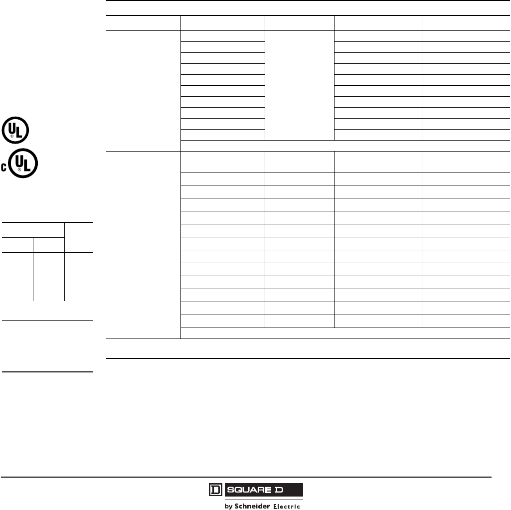
Class 8940 Type NP IEC Style Pump Panels, in NEMA Type 3R enclosures, are specifically designed
for irrigation applications. All panels are supplied with a visible-blade fused disconnect switch (unless
noted). Extra panel space is provided for field installation of auxiliary equipment (refer to page 12 for
approximate dimensions).
•Approved for submersible pump applications
•Class 10 bimetallic overload relay through 100 hp-480 V, 50 hp–240 V
•Adjustable trip current
•Includes a Start push button and a Hand-Off-Auto selector switch
•Ambient temperture compensated
•TeSys™ D and TeSys™ F contactors are used as standard
•Sizes closely matched to common motor sizes
•All devices are UL Listed and marked “SUITABLE ONLY FOR USE AS SERVICE EQUIPMENT”
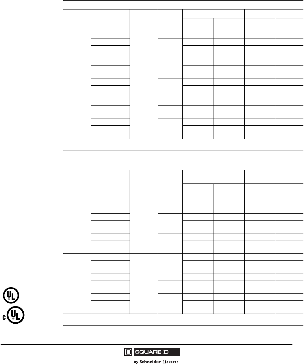
Fusible Disconnect Switch Type
600 Volts Max. – 3-Pole – 50-60 Hertz
Volts Max. hp Polyphase Coil Voltage kFuse Clip Amperes qClass 8990 Type c
240
3
240-60
220-50
30 NPD2003V03
5 30 NPE2005V03
7.5 30 NPE2007V03
10 60 NPF2010V03
15 60 NPF2015V03
20 100 NPG2020V03
25 100 NPG2025V03
30 100 NPJ2030V03
40 200 NPJ2040V03
50 200 NPJ2050V03
Above 50 hp, see page 4
480
3480-60
440-50 30 NPD4003V06
5 30 NPD4005V06
7.5 30 NPD4007V06
10 30 NPE4010V06
15 30 NPE4015V06
20 60 NPF4020V06
25 60 NPF4025V06
30 60 NPF4030V06
40 100 NPG4040V06
50 100 NPG4050V06
60 100 NPJ4060V06
75 200 NPJ4075V06
100 200 NPJ4100V06
Above 100 hp, see page 4.
k Coil voltage code must be specified to order this product. Refer to standard voltage codes listed at left.
q Fuse clips are sized for use with dual-element time-delay fuses.
Listed File
E152395
Listed File
E152395
Coil Voltage Codes
Voltage
Code
60 Hz 50 Hz
24 jp . . . V01
120 j110 V02
208 j. . . V08
240 220 V03
. . . 380 V05
480 440 V06
600 j 550 V07
For hp higher than 100, see
page 4.
p Must be specially
wound for NPJ devices.
j Form S (separate
control) required for
24 V, 120 V, 208 V, and
600 V coils.
© 1997-2008 Schneider Electric
All Rights Reserved
Well-Guard Control™ Pump Panels, Full Voltage–Class 8940
Irrigation and Oil Field Style Selection Guide
4
09/2008
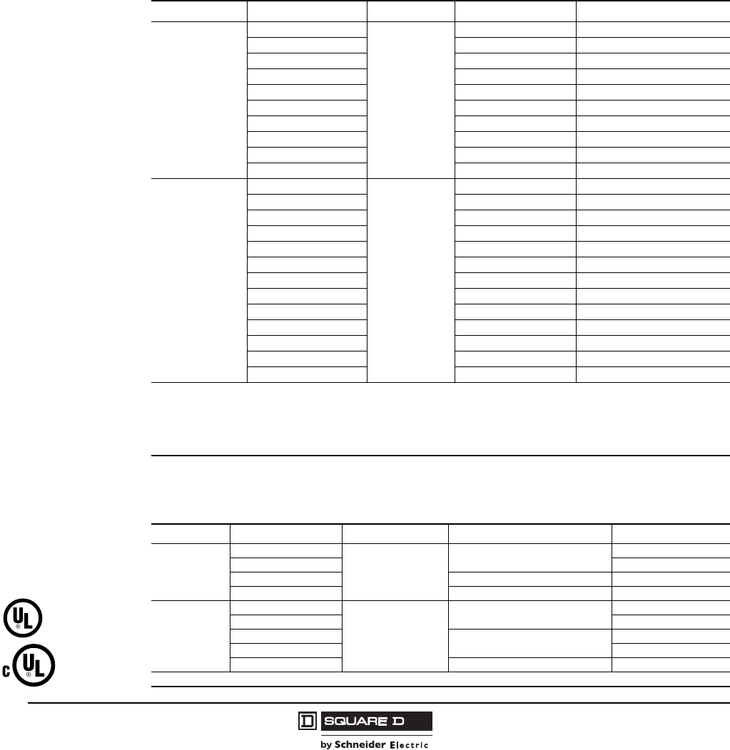
Class 8940 Type NS, SS and XS Pump Panels, in NEMA Type 3R enclosures, are specifically
designed for irrigation and oil field applications. All panels are supplied with a visible-blade fused
disconnect switch (unless noted). Extra panel space is provided for field installation of auxiliary
equipment (refer to page 12 for approximate dimensions).
•Type S contactor provided as standard
•Approved for submersible pump applications
•Class 10 Motor Logic® SSOLR through 200 hp-480 V, 100 hp-240V —Type SS*
•Includes a Start push button and a Hand-Off-Auto selector switch
•Adjustable trip current
•Ambient temperature compensated
•All devices are UL Listed and marked “SUITABLE ONLY FOR USE AS SERVICE EQUIPMENT”
NOTE: The Class 10 Motor Logic SSOLR (solid-state overload relay) does not protect for phase imbalance;
however, it does include a rubber boot dust cover.
3-Pole Polyphase – 600Vac Maximum (50-60 Hz) – Fusible Disconnect Switch Type
NOTE: To substitute an ambient compensated bimetallic overload relay (up to size 4) for the Motor Logic SSOLR,
request Form B12 and state motor hp (no charge).
3-Pole Polyphase – 600 Volts AC Maximum (50-60 Hz) – Circuit Breaker
Volts Max. hp Polyphase Coil Voltage jFuse Clip Amperes qClass 8940 Type c
240
3, 5, 7.5
240-60
220-50
30 SSC2007 f
10, 15 60 SSD2015 f
20, 25, 30 100 SSE2030 f
40, 50 200 SSF2050 f
75 LAL36250 tXSG2075V03 c
100 400 SSG2100
100 LAL36350 tXSG2100V03 c
200 MAL36700 tXSH2200V03 c
250 MAL36800 tXSJ2250V03 c
300 MAL361000 tXSJ2300V03 c
480
3, 5, 7.5, 10
480-60
440-50
30 SSC4010 f
15, 20, 25 60 SSD4025 f
30 60 SSD4030 f
40, 50 100 SSE4050 f
60, 75, 100 200 SSF4100 f
150 LAL36250 tXSG4150V06 c
200 400 SSG4200
200 LAL36350 tXSG4200V06 c
300 MAL36500 tXSH4300V06 c
350 MAL36600 tXSH4350V06 c
400 MAL36700 tXSH4400V06 c
500 MAL36800 tXSJ4500V06 c
600 MAL361000 tXSJ4600V06 c
t MAG-GARD circuit breaker disconnect supplied.
q Fuse clips are sized for use with dual-element time-delay fuses.
f Voltage code not required for 240 V or 480 V with 8940SS___ controllers.
c Type SSC, SSD, SSE, SSF, SSG, and XSJ panels include the Motor Logic SSOLR and do not require thermal units. Types
XSG and XSH panels include a three-unit overload relay. Thermal units must be ordered separately. See Pages 8-9 for
selection information.
Volts Max. hp Polyphase Coil Voltage jCircuit Breaker Class 8940 Type
240
25
240-60
220-50
FAL36100-18M XSE2025V03
30 XSE2030V03
40 KAL36250-26M XSE2040V03
50 KAL36250-29M XSE2050V03
480
40
480-60
440-50
FAL36100-18M XSE4040V06
50 XSE4050V06
60 KAL36250-25M XSE4060V06
75 XSE4075V06
100 KAL36250-29M XSE4100V06
j See Page 3 for coil voltage codes.
Listed File
E152395
Listed File
E152395
Well-Guard Control™ Pump Panels, Full Voltage–Class 8940
Oil Field Style Selection Guide
5
09/2008
© 1997-2008 Schneider Electric
All Rights Reserved
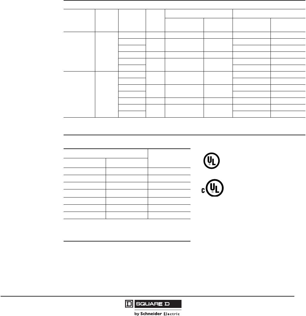
Class 8940 Type S2 Pump Panels, in NEMA Type 3R enclosures, are specifically designed for Oil
Field applications. All panels are supplied with a visible-blade fused disconnect switch or a Mag-Gard®
circuit breaker, depending on the Type number. Extra panel space is provided for field installation of
auxiliary equipment (refer to page 12 for approximate dimensions).
•Rugged spring latches for easy access without a tool
•Side mounted control units for convenient operation
•Door retainer available for windy areas (Form G45)
•Hand-Off-Auto selector switch
•UL Listed for use as Service Equipment for Motors
•Extra panel space for additional electrical controls
•All devices UL Listed and marked “SUITABLE ONLY FOR USE AS SERVICE EQUIPMENT”
NOTE: Overload relays are ambient temperature compensated.
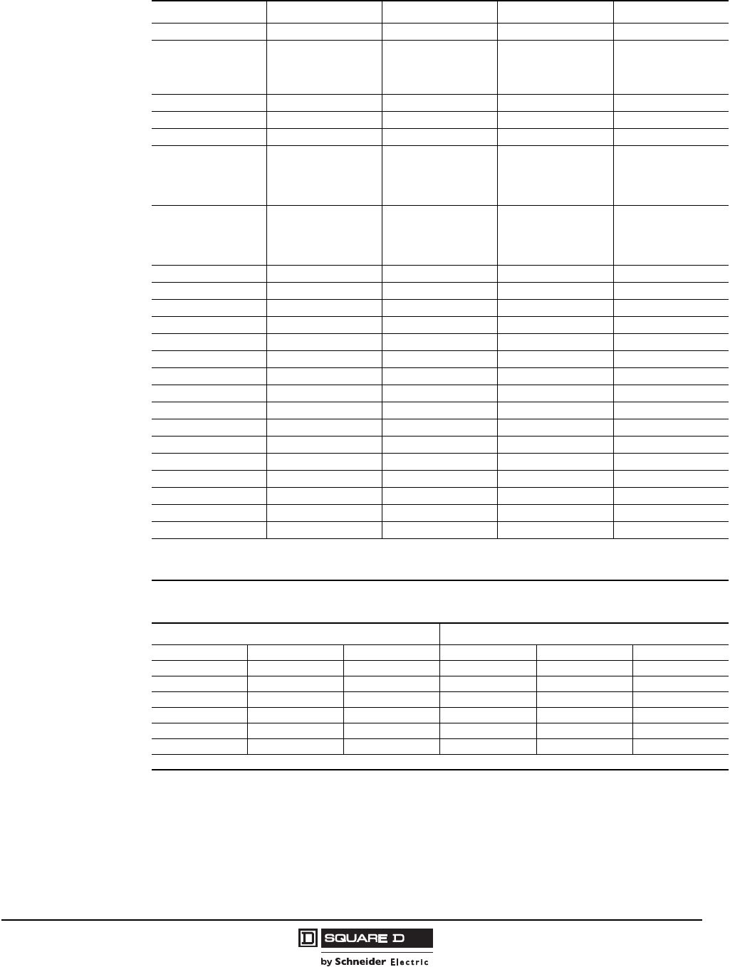
Coil Voltage Codes
600 Volts Max. – 3-Pole – 50-60 Hertz
Volts Coil
Voltage t
Max. hp
Polyphase
NEMA
Size
Fusible Disconnect Type Circuit Breaker Type
Fuse Clip
Amperes a
Class 8940
Type Frame Size Class 8940
Type
240
240 @
60 Hz
220 @
50 Hz
7.5 1 30 WC1S2V03 GJL36030M04 XC1S2V03
10 2 60 WD1S2V03 GJL36050M05 XD1S2V03
15 FAL3610018M XD2S2V03
30 3 100 WE1S2V03 FAL3610018M XE1S2V03
40 4 200 WF1S2V03 KAL3625026M XF1S2V03
50 KAL3625029M XF2S2V03
480
480 @
60 Hz
440 @
50 Hz
7.5 1 30 WC3S2V06 GJL36015M03 XC3S2V06
10 GJL36030M04 XC4S2V06
15 2 60 WD3S2V06 GJL36030M04 XD3S2V06
25 GJL36050M05 XD4S2V06
50 3 100 WE3S2V06 FAL3610018M XE3S2V06
75 4 200 WF3S2V06 KAL3625025M XF3S2V06
100 KAL3625029M XF4S2V06
aFuse clips are sized for use with dual-element time-delay fuses.
kThermal units must be ordered separately.
tCoil voltages must be specified to order this product. See coil voltage codes below.
Voltage
Code
60 Hz 50 Hz
24 jq —V01
120 j110 V02
208 j—V08
240 220 V03
— 380 V05
480 440 V06
600 j550 V07
q24V coils are not available on Size 4 starters.
On Size 1-3, 24V coils are available. Form S must be used.
jForm S (separate control) required for 24 V, 120 V, 208 V, and
600 V coils.
Listed File E152395
CCN NKJH
Listed File E152395
CCN NKJH7
© 1997-2008 Schneider Electric
All Rights Reserved
Well-Guard Control™ Pump Panels, Full Voltage–Class 8940
Factory Modifications
6
09/2008
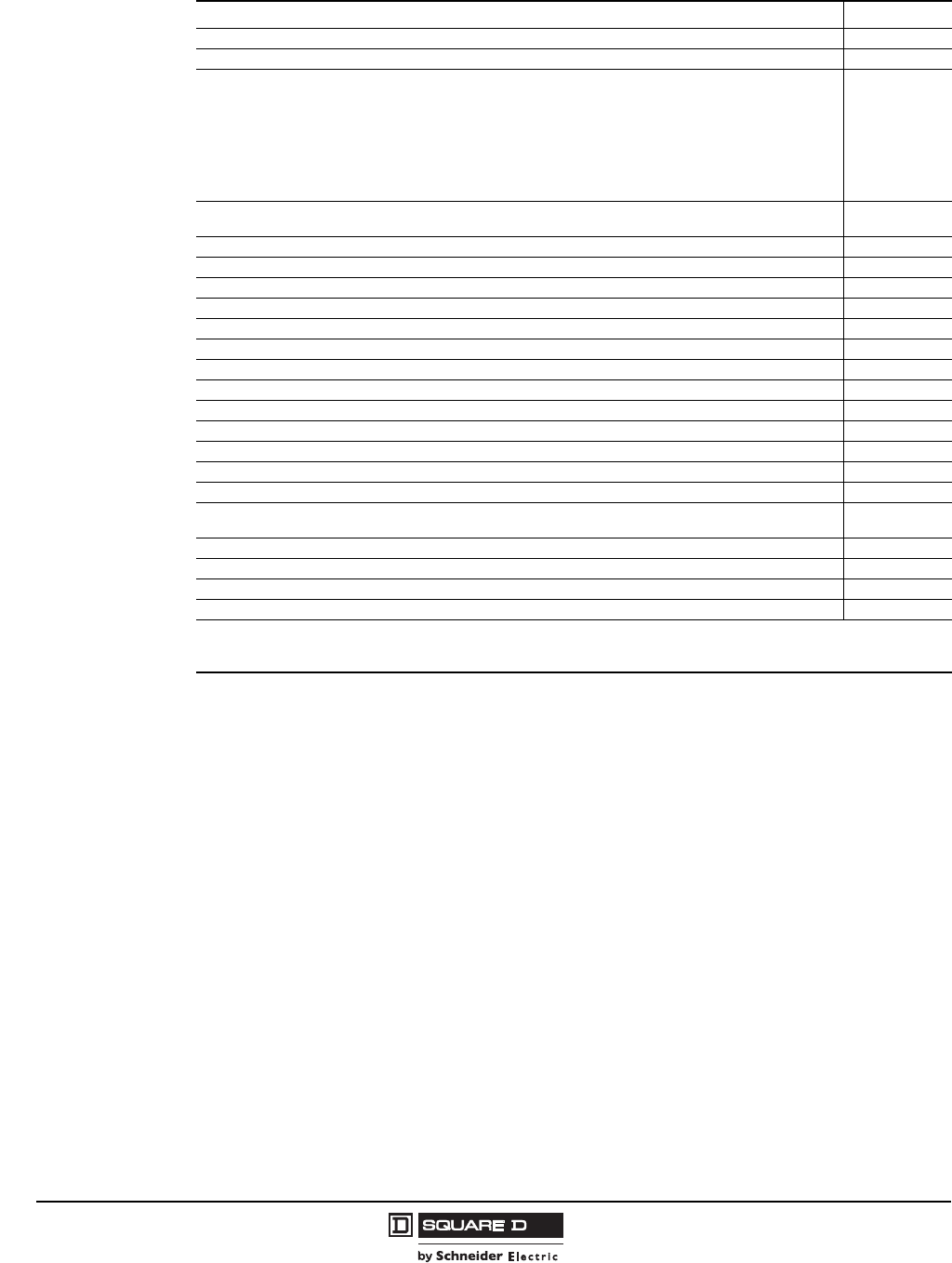
Factory Modifications
Description Form
Start push button in oil field panel (S2) only A28
Substitute Class 10 IEC overload relay – state motor hp B12
Control Transformer with Fused Primary:
Types:
NPD, NPE, NPF, WC, XC, NSC, SSC (50 VA)
NPG, NSG, XD, WD, SSD (100 VA)
NPJ, NSE, XE, WE, SSE (150 VA)
NSF, XF, WF, SSF (300 VA)
NSG, XSG, (50 VA and an interposing control relay)
F4T
Door wind latch assembly, factory installed in a standard 8940NPD, NPE, NPF, NPG, NPJ, SSC, SSO, SSE, or
SSF panel. G45
Elapsed time meter G97
Substitute Class 10 Motor Logic® SSOLR (without phase imbalance protection) H10
On delay timer, 0.1 seconds to 1 minute K25
Off delay timer, 0.1 seconds to 1 minute K26
On delay timer, 1 minute to 3 minute K37
Off delay timer, 1 minute to 3 minute K38
Backspin timer (time delay on energization) K15
Slim panel (Types WC, WD, WF, XC, XD, XF only) L8
Short Panel (Types SSE, SSF only) L9
Pilot light, red (does not include auxiliary contact) P1
Pilot light, green (does not include auxiliary contact) P2
Separate Control S
Auxiliary Contacts (Specify N.O. or N.C.) X q
Special UL panel label for modified UL Listed devices on non-standard panels. Requires approval by
manufacturing plant. Y1
Lightning Arrester Y1532
Phase failure, phase reversal relay with time delay, including undervoltage and overvoltage protection R44 j
Substitute Standard-Trip Melting Alloy Overload Relays (Type S2 only) Y61
Substitute Quick-Trip Melting Alloy Overload Relay (Type S2 only) Y611
jRequires the use of 120 volt control (Form S or FF4T).
qTo determine the maximum number of auxiliary contacts which can be added to each Type S device, and for the appropriate X
Form, refer to tables in the Class 8536 section of the current Digest.
Well-Guard Control™ Pump Panels, Full Voltage–Class 8940
Reduced Voltage Type
7
09/2008
© 1997-2008 Schneider Electric
All Rights Reserved
Class 8940 Reduced Voltage panels in NEMA Type 3R enclosures are specifically designed for
pumping applications. Extra space is provided for field installation of auxiliary equipment.
•Type S contactors/starters provided as standard.
•All devices are UL Listed and marked “SUITABLE ONLY FOR USE AS SERVICE EQUIPMENT.”
•Includes Hand-Off-Auto selector switch and Start push button.
Closed Transition Autotransformer Type
Part Winding Type
3-Pole Polyphase – 600 Volts AC Maximum – 50-60 Hertz
Motor
(Starter)
Volts
Max. hp
Polyphase
Coil
Voltage
NEMA
Size
Fusible Disconnect Type Circuit Breaker Type
Fuse Clip
Amperes a
Class 8940
Type k
Circuit
Breaker
Class 8940
Type k
230
(240)
15
240 @ 60 Hz
220 @ 50 Hz
2 60 RD4DV03 FAL36080 VD1DV03
25 3100 RE4FV03 FAL36100 VE1FV03
30 200 RE1GV03 KAL36100 VE2GV03
50 4 200 RF4JV03 KAL36200 VF1JV03
75 5400 RG1LV03 LAL36250 VG2LV03
100 400 RG1MV03 LAL36350 VG2MV03
460
(480)
25
480 @ 60 Hz
440 @ 50 Hz
2 60 RD2FV06 FAL36070 VD1FV06
30 3100 RE2GV06 FAL36080 VE1GV06
50 100 RE2JV06 FAL36100 VE1JV06
75 4200 RF2LV06 KAL36125 VF1LV06
100 200 RF2MV06 KAL36200 VF1MV06
150 5400 RG3PV06 LAL36250 VG4PV06
200 400 RG3QV06 LAL36350 VG4QV06
300 6— — MAL36600 VH1SV06
400 — — MAL36900 VH2TV06
600 7 — — MAL36100 VJ1WV06
aFuse clips are sized for use with dual-element time-delay fuses.
kThermal units must be ordered separately.
3-Pole Polyphase – 600 Volts AC Maximum – 50-60 Hertz
Motor
(Starter)
Volts
Max. hp
Polyphase
Coil
Voltage
NEMA
Size
Combination Fusible
Disconnect Type
Combination Circuit Breaker
Type
Fuse Clip
(2 sets)
Amperes a
Class 8940
Type k
Circuit
Breaker (2
Bkrs.)
Frame Size
Class 8940
Type k
230
(240)
25
240 @ 60 Hz
220 @ 50 Hz
2PW 60 MD4FV03 FAL36070 PD1FV03
30 3PW 60 ME5GV03 FAL36080 PE3GV03
50 100 ME6JV03 FAL36100 PE3JV03
75 4PW 200 MF1LV03 KAL36150 PF3LV03
100
5PW
200 MG3MV03 KAL36175 PG2MV03
125 400 MG1NV03 LAL36250 PG3NV03
150 400 MG1PV03 LAL36250 PG3PV03
460
(480)
30
480 @ 60 Hz
440 @ 50 Hz
2PW 30 MD5GV06 FAL36040 PD1GV06
40 60 MD2HV06 FAL36050 PD1HV06
60 3PW 60 ME7KV06 FAL36070 PE3KV06
75 100 ME3LV06 FAL36090 PE3LV06
100 4PW 200 MF3MV06 FAL36100 PF2MV06
150 200 MF3PV06 KAL36125 PF3PV06
200
5PW
200 MG4QV06 KAL36175 PG2QV06
250 200 MG4RV06 LAL36225 PG3RV06
400 400 MG2TV06 LAL36300 PG3TV06
aFuse clips are sized for use with dual-element time-delay fuses.
kThermal units required. Order separately. Refer to pages 10–11.
Listed File E152395
CCN NKJH
Listed File E152395
CCN NKJH7

© 1997-2008 Schneider Electric
All Rights Reserved
Well-Guard Control™ Pump Panels, Full Voltage–Class 8940
Replacement Part Application Data
8
09/2008
Application Data
Class 8940 Type Disconnect
Switch Fuse Base Contactor Overload Relay Overload Relay
Mounting Bracket
NPD2003 40567-200-51t40566-143-51 LC1D12 LRD16 LAD7B10
NPE2005 40567-200-51t40566-143-51 LC1D18 LRD21 LAD7B10
NPE2007 40567-200-51t40566-143-51 LC1D25 LRD22 LAD7B10
NPF2010 40567-200-51t
40566-143-51
(60 A 250 V)
40566-144-51
(60 A 600 V)
LC1D32 LRD32 LAD7B10
NPF2015 40567-200-51t
40566-143-51
(60 A 250 V)
40566-144-51
(60 A 600 V)
LC1D50 LRD3357 LA7D3064
NPG2020 31301-056-65 31301-059-50 LC1D65 9065TJF40 NA
NPG2025 31301-056-65 31301-059-50 LC1D80 9065TJF40 NA
NPJ2030 31301-056-65 31301-059-50 LC1F115 9065TJF63 NA
NPJ2040 31055-366-51 Included with switch LC1F115 9065TJF63 NA
NPJ2050 31055-366-51 Included with switch LC1F150 9065TJF100 NA
NPD4003 40567-200-51t40566-143-51 LC1D09 LRD10 LAD7B10
NPD4005 40567-200-51t40566-143-51 LC1D09 LRD12 LAD7B10
NPD4007 40567-200-51t40566-143-51 LC1D12 LRD16 LAD7B10
NPE4010 40567-200-51t40566-143-51 LC1D18 LRD21 LAD7B10
NPE4015 40567-200-51t40566-143-51 LC1D25 LRD22 LAD7B10
NPF4020 40567-200-51t
40566-143-51
(60 A 250 V)
40566-144-51
(60 A 600 V)
LC1D32 LRD32 LAD7810
NPF4025 40567-200-51t
40566-143-51
(60 A 250 V)
40566-144-51
(60 A 600 V)
LC1D40 LRD3355 LA7D3064
NPF4030 40567-200-51t40566-144-51
(60 A 250 V) LC1D50 LRD3357 LA7D3064
NPG4040 31301-056-65 31301-059-50 LC1D65 9065TJF40 NA
NPG4050 31301-056-65 31301-059-50 LC1D80 9065TJF40 NA
NPJ4060 31301-056-65 31301-054-50 LC1F115 9065TJF63 NA
NPJ4075 31055-366-51 Included with switch LC1F115 9065TJF63 NA
NPJ4100 31055-366-51 Included with switch LC1F150 9065TJF100 NA
tIncludes switch base and operating mechanism. To ensure handle compatibility, part number HM0610F must also be
purchased.
NOTE: Two operating mechanisms will be shipped; keep one mechanism as a spare.
Well-Guard Control™ Pump Panels, Full Voltage–Class 8940
Replacement Part Application Data
9
09/2008
© 1997-2008 Schneider Electric
All Rights Reserved
Application Data
Class 8940 Electrical Interlocks
Class 8940 Type Disconnect Switch Fuse Base Contactor Overload Relay
SSC2007 40567-200-51t40566-143-51 8502SCO2 31161-547-64
SSD2015 40567-200-51t
40566-143-51
(60 A 250 V)
40566-144-51
(60 A 600 V)
8502SDO2 31161-548-83
SSE2030 31301-056-65 31301-059-50 8052SEO2 31161-551-58
SSF2050 31055-366-51 Included with switch 8502SFO2 31161-551-58
SSC4010 40567-200-51t40566-143-51 8052SCO2 31161-547-64
SSD4025 40567-200-51t
40566-143-51
(60 A 250 V)
40566-144-51
(60 A 600 V)
8502SDO2 31161-548-83
SSD4030 40567-200-51t
40566-143-51
(60 A 250 V)
40566-144-51
(60 A 600 V)
8502REQ2617G 31161-548-83
SSE4050 31301-056-65 31301-059-50 8502SEO2 31161-551-58
SSF4100 31055-366-51 Included with switch 8502SFO2 31161-553-68
XSG2075 LAL36250 NA 8502SGO2 9065SE06B
SSG2100 9422TG2 NA 31102-668-50 31161-184-74
XSG2100 LAL36350 NA 8502SGO2 9065SE06B
XSH2200 MAL36700 NA 8536SHO2 9065SE06B
XSJ2250 MAL36800 NA 8536JO2 9065SE06B
XSJ2300 MAL361000 NA 8536JO2 9065SE06B
XSG4150 LAL36250 NA 8502SGO2 9065SE06B
SSG4200 9422TG2 NA 31102-668-00 31161-184-74
XSG4200 LAL36350 NA 8502SGO2 9065SE06B
XSH4300 MAL36500 NA 8536SHO2 9065SE06B
XSH4300 MAL36600 NA 8536SHO2 9065SE06B
XSH4400 MAL36700 NA 8536SHO2 9065SE06B
XSJ4500 MAL36800 NA 8536JO2 31161-184-77
XSJ4600 MAL361000 NA 8536JO2 31161-184-77
tIncluses switch base and operating mechanism. To ensure handle compatibility, part number HM0610F must also be
purchased.
NOTE: Two operating mechanisms will be shipped; keep one as a spare.
Disconnect Switches Circuit Breakers
Rating Style
SPDT DPDT SPDT DPDT
30A EIK1tEIK2tGJL NA NA
60A EIK1tEIK2tFAL 9999R26 9999R27
100A 9999TC10 9999TC20 KAL 9999R26 9999R27
200A 9999R39 9999R40 LAL 9999R26 9999R27
400A 9999R35 9999R36 MAL 9999R26 9999R27
tNo class number required.

© 1997-2008 Schneider Electric
All Rights Reserved
Well-Guard Control™ Pump Panels, Full Voltage–Class 8940
Thermal Units
10
09/2008
Bimetallic Thermal Unit Selection Tables Based on Motor Full Load Current
Table A - NEMA Size 1 (Table 33)
Table B - NEMA Size 2k (Table 70)
Table C - NEMA Size 3k (Table 37)
tThese thermal unit selections are for controllers protected from
solar radiation and located in an ambient temperature of 40 oC
(104 oF) or less. For overload relays which are not ambient
temperature compensated (NEMA Size 3 and 4), thermal units
larger than normal can be required under conditions of high
ambient temperature and/or solar radiation. Consult your local
Square D field office.
kTo select thermal units for Type M part winding devices, first
divide total motor full load current by 2. Use tables above.
NOTE: This is a partial Thermal Unit Selection Table
listing. The complete list can be found in the current
Digest.
Table D - NEMA Size 4k (Table 29)
Table E- NEMA Size 5qk (Table 46)
Table F- NEMA Size 6q (Table 47)
Table G- NEMA Size 7
Motor Logic SSOLR
Adjustable 270-810 Full Load Current (Ambient Insensitive)
Types WC, XC
Motor Amperes Thermal Unit
6.28-6.97
6.98-7.59
7.60-7.89
7.90-8.95
8.96-10.3
10.4-11.7
11.8-13.3
13.4-15.2
15.3-17.2
17.3-19.7
19.8-22.4
22.5-26.0
AR 10.2
AR 11.2
AR 12.4
AR 13.6
AR 15.4
AR 17.6
AR 20.5
AR 23
AR 27
AR 30
AR 35
AR 40
Types MD, PD, RD, VD,WD, XD
Motor Amperes Thermal Unit
8.56-9.74
9.75-11.1
11.2-12.7
12.8-14.4
14.5-16.4
16.5-18.9
19.0-21.6
21.7-23.3
23.4-24.9
25.0-26.9
27.0-29.1
29.2-31.3
31.4-33.5
33.6-36.9
37.0-39.1
39.2-40.9
41.0-45.0
AR 17.6
AR 20.5
AR 23
AR 27
AR 30
AR 35
AR 40
AR 44
AR 47
AR 51
AR 55
AR 60
AR 66
AR 72
AR 79
AR 86
AR 94
Types ME, PE, RE, VE, WE, XE
Motor Amperes Thermal Unit
27.1-30.0
30.1-33.2
33.3-35.7
35.8-39.4
39.5-43.4
43.5-46.9
47.0-51.5
51.6-57.0
57.1-62.8
62.9-69.1
69.2-75.0
75.1-83.3
E 67
E 69
E 70
E 71
E 72
E 73
E 74
E 76
E 77
E 78
E 79
E 80
Types MF, PF, RF, VF, WF, XF
Motor Amperes Thermal Unit
50.0-55.9
56.0-60.9
61.0-65.9
66.0-69.9
70.0-75.9
76.0-81.9
82.0-86.9
87.0-92.9
93.0-97.9
98.0-107.9
108.0-113.9
114.0-125.9
E 88
E 89
E 91
E 92
E 93
E 94
E 96
E 97
E 98
E 99
E 101
E 102
uOrder Type E thermal units by number from Square D
Company, Furnas Electric Company, Batavia, IL or a
Furnas Distributor.
Types MG, PG, RG, VG, WG, XG
Motor Amperes Thermal Unit
105-116
117-132
133-148
149-165
166-184
185-207
208-229
230-266
AR 3.28
AR 3.62
AR 3.98
AR 4.37
AR 4.80
AR 5.30
AR 5.8
AR 6.4
qWith 300:5 Current Transformer Ratio. Across-the-line and
auto-transformer type reduced voltage.
Type VH, XH
Motor Amperes Thermal Unit
146-169
170-185
186-201
202-217
218-236
237-253
254-279
280-311
312-353
354-396
397-442
443-492
493-520
AR 1.68
AR 1.85
AR 2.04
AR 2.24
AR 2.46
AR 2.71
AR 2.98
AR 3.28
AR 3.62
AR 3.98
AR 4.37
AR 4.80
AR 5.30
qWith 800:5 Current Transformer Ratio. Auto-transformer
type reduced voltage.
Type
Motor Amperes Thermal Unit

Well-Guard Control™ Pump Panels, Full Voltage–Class 8940
Thermal Units
11
09/2008
© 1997-2008 Schneider Electric
All Rights Reserved
Melting Alloy Quick Trip Thermal Unit Selection Tables (Form Y611)
Based on Motor Full Load Currentt
Table H- NEMA Size 1 (Table 78)
Table J - NEMA SIZE 3 (Table 80)
Table I - NEMA SIZE 2 (Table 79)
Table K - NEMA SIZE 4 (Table 81)
tThese thermal unit selections are for controllers protected
from solar radiation and located in an ambient temperature
of 40oC (104oF) or less. For overload relays which are not
ambient temperature compensated (NEMA Size 3 and 4),
thermal units larger than normal can be required under
conditions of high ambient temperature and/or solar
radiation. Consult your local Square D field office.
NOTE: This is a partial Thermal Unit Selection
Table listing. The complete list can be found in
the current Digest.
Types WC, XC
Motor Amperes Thermal Unit
2.26-2.51
2.52-2.81
2.82-3.09
3.10-3.30
3.31-3.69
3.70-4.27
4.28-4.72
4.73-5.25
5.26-5.53
5.54-5.81
5.82-6.14
6.15-6.44
6.45-6.81
6.82-7.19
7.20-7.59
7.60-7.99
8.00-8.17
8.18-8.74
8.75-9.31
9.32-9.94
9.95-10.5
10.6-11.1
11.2-12.0
12.0-12.4
12.5-13.1
13.2-14.3
14.4-15.3
15.4-15.9
16.0-16.9
17.0-18.3
18.4-19.5
19.6-20.5
20.6-21.1
21.2-22.6
22.7-23.7
23.8-24.3
24.4-26.0
FB 3.33
FB 3.71
FB 4.1
FB 4.5
FB 4.75
FB 5.3
FB 6.1
FB 6.75
FB 7.45
FB 7.8
FB 8.2
FB 8.6
FB 9.0
FB 9.5
FB 10
FB 10.6
FB 11.2
FB 12.1
FB 13.1
FB 13.9
FB 14.8
FB 15.6
FB 16.4
FB 17.6
FB 18.4
FB 19.4
FB 21.1
FB 22.6
FB 23.6
FB 24.8
FB 26.7
FB 28.3
FB 29.6
FB 30.5
FB 32.6
FB 34.1
FB 35
Types WE, XE
Motor Amperes Thermal Unit
20.5-21.7
21.8-23.1
23.2-24.8
24.9-26.5
26.6-28.4
28.5-30.4
30.5-32.8
32.9-34.9
35.0-37.3
37.4-39.8
39.9-42.5
42.6-45.8
45.9-48.2
48.3-50.6
50.7-53.1
53.2-56.5
56.6-59.4
59.5-63.4
63.5-71.0
71.1-78.8
78.9-86.0
FB 26.7
FB 28.3
FB 29.6
FB 30.5
FB 32.6
FB 34.1
FB 38.3
FB 40.2
FB 42
FB 44
FB 46
FB 48
FB 50.5
FB 52.5
FB 55.5
FB 58
FB 60
FB 63.5
FB 69
FB 77
FB 84
Types WD, XD
Motor Amperes Thermal Unit
4.24-4.69
4.70-5.21
5.22-5.49
5.50-5.74
5.75-6.07
6.08-6.35
6.36-6.71
6.72-7.03
7.04-7.53
7.54-7.91
7.92-8.53
8.54-9.14
9.15-9.71
9.72-10.2
10.3-10.8
10.9-11.5
11.6-12.3
12.4-13.0
13.1-13.9
14.0-15.1
15.2-16.1
16.2-16.9
17.0-17.9
18.0-19.4
19.5-20.7
20.8-21.7
21.8-22.3
22.4-23.9
24.0-25.1
25.2-25.9
26.0-27.1
27.2-28.6
28.7-30.1
30.2-31.7
31.8-33.3
33.4-34.5
34.6-36.5
36.8-38.5
38.6-39.9
40.0-45.0
FB 6.1
FB 6.75
FB 7.45
FB 7.8
FB 8.21
FB 8.6
FB 9.0
FB 9.5
FB 10
FB 10.6
FB 11.2
FB 12.1
FB 13.1
FB 13.9
FB 14.8
FB 15.6
FB 16.4
FB 17.6
FB 18.4
FB 19.4
FB 21.1
FB 22.6
FB 23.6
FB 24.8
FB 26.7
FB 28.3
FB 29.6
FB 30.5
FB 32.6
FB 34.1
FB 35
FB 36.6
FB 38.3
FB 40.2
FB 42
FB 44
FB 46
FB 48
FB 50.5
FB 52.5
Types WF, XF
Motor Amperes Thermal Unit
52.2-55.6
55.7-58.8
58.9-62.5
62.6-66.0
66.1-70.1
70.2-78.6
78.7-92.0
92.1-102
103-114
115-123
124-133
FB 50.5
FB 52.5
FB 55.5
FB 58
FB 60
FB 63.5
FB 69
FB 77
FB 84
FB 92
FB 105
© 1997-2008 Schneider Electric
All Rights Reserved
Well-Guard Control™ Pump Panels, Full Voltage–Class 8940
Replacement Part Application Data
12
09/2008
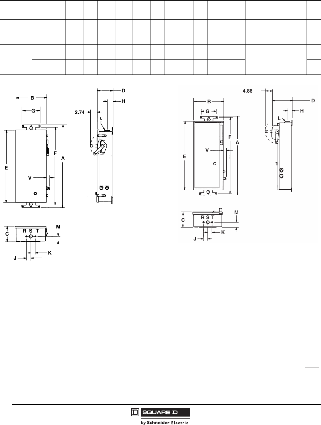
Approximate Dimensions
Type Fig. Dim. A B C D E F G H J K Conduit
LM
Knockout
V
RS T
NPD
NPE
NPF
SSC
1
in. 39.05 13.73 6.67 9.70 33.05 37.93 7.00 2.41 3.00 3.00
1-1/2
2.41
1/2, 3/4 1-1/4,
1-1/2 1/2,3/4
1.41
mm 992 349 169 246 839 963 178 61 76 76 61 36
NPG
NPJ
SSE
SSF
XSE
2
in. 49 19.15 8.81 10.37 44.07 47.88 7.00 2.17 2.69 3.44 2-1/2 2.57
1/2, 3/4 1-1/4
1,2-1/2
1,1-1/4
1-1/2,2
1.41
mm 1245 486 249 263 1119 1216 178 55 68 87 65 36
Handle
Swing
Figure 1 Figure 2
Dual Dimensions:mm
in.
Well-Guard Control™ Pump Panels, Full Voltage–Class 8940
Replacement Part Application Data
13
09/2008
© 1997-2008 Schneider Electric
All Rights Reserved
Approximate Dimensions
TypeFig.DimensionsABCDEFGHJK
Conduit
LM
Knockout
V
RS T
WC-S2
WD-S2
XC-S2
1
in. 38.50 19.00 7.29 9.39 34.00 37.38 7.00 2.18 2.13 2.13
1-1/2
2.12
1/2-3/4 1, 1-1/4,
1-1/2 1/2, 3/4
—
mm 978 483 185 539 864 949 178 55 54 54 54 —
WE-S2
WF-S2
XE-S2
1
in. 56.50 23.00 8.23 10.33 52.00 55.38 7.00 2.18 2.69 3.44
1/2
2.68
1/2-3/4 1, 1-1/4,
2, 2-1/2
1, 1-1/4
1-1/2, 2
1.50
mm 1435 584 209 262 1321 1407 178 55 68 87 68 38
NSG
XSG 2in. 74.50 22.00 13.80 17.55 73.00 0.50 14.00 — 0.56 — — — — — — 1.50
mm 1892 559 351 446 1854 13 356 — 14 — — — — — — 38
XSH 3 in. 82.5036.0020.0023.2580.0033.7516.50———— —— — — —
mm 20969145085912032857419———— —— — — —
XSJ 3 in. 92.5034.0020.0023.2590.0031.7516.50———— —— — — —
mm 23508645085912286806419———— —— — — —
Dia. Mtg. HolesDia. Mtg. Holes
Dia. Mtg. Holes
Figure 1 Figure 2 Figure 3
Dual Dimensions:mm
in.

© 1997-2008 Schneider Electric
All Rights Reserved
Well-Guard Control™ Pump Panels, Full Voltage–Class 8940
Replacement Part Application Data
14
09/2008
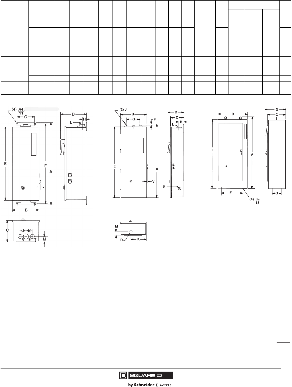
Part Winding - Reduced Voltage Type
Auto-transformer - Reduced Voltage Type
Type Dimensions tA B C D E F Figure
PD in. 19.00 34.50 12.25 13.00 33.50 0.44 2
mm 483 876 311 330 851 11
MD in. 23.00 25.50 10.60 17.00 24.50 0.44 1
mm 584 648 269 432 622 11
PE
PF
in. 30.00 47.00 13.25 22.00 46.00 0.56 2
mm 762 1194 337 559 1168 14
ME in. 25.00 52.50 12.13 19.00 51.50 0.44 2
mm 635 1334 308 483 1308 11
MF in. 36.00 93.00 19.25 33.75 12.50 0.69 3
mm 914 2362 489 857 318 18
PG
MG
in. 36.00 73.00 19.25 33.75 12.50 0.69 3
mm 914 1854 489 857 318 18
PH in. 38.00 93.00 19.25 35.75 12.50 0.69 3
mm 965 2362 489 908 318 18
Type Dimensions tABCDEF Figure
RD
VD
in. 25.00 52.50 11.13 19.00 51.50 0.44 2
mm 635 1334 283 483 1308 11
RE, VE
RF, VF
in. 32.00 72.50 19.25 29.75 12.50 0.68 3
mm 813 1842 489 756 318 17
RG in. 36.00 93.00 19.25 33.75 12.50 0.69 3
mm 914 2362 489 857 318 17
VG in. 32.00 72.50 19.25 29.75 12.50 0.68 3
mm 813 1842 489 756 318 17
VH in. 34.00 93.00 23.25 3133.75 16.50 0.69 3
mm 864 2362 591 806 419 17
VJ jin. 64.00 93.00 27.25 61.75 17.25 0.81 3✝
mm 1626 2362 692 1568 438 21
jCabinet has double doors
Figure 1 Figure 2 Figure 3
t
Dual Dimensions:mm
in.

Well-Guard Control™
Replacement Part Application Data
15
09/2008
© 1997-2008 Schneider Electric
All Rights Reserved

8940CT9701R7/08 © 1997-2008 Schneider Electric All Rights Reserved
Replaces 8940CT9701, December 1997
09/2008
Schneider Electric USA
8001 Knightdale Blvd.
Knightdale, NC 27545
1-888-Square D
1-888-778-2733
www.schneider-electric.us
