Freescale MQX™ RTOS BSP Porting Example User Guide MQX
User Manual: Pdf
Open the PDF directly: View PDF ![]() .
.
Page Count: 43
- Freescale MQX™ RTOS BSP Porting Example User's Guide
- 1 Introduction
- 2 Example
- 3 Cloning the BSP
- 4 Using Processor Expert (PEx) in the BSP
- 4.1 Setting up BSP for PEx with IAR EW-ARM
- 4.2 Setting up BSP for PEx with Keil µVision®
- 5 Changing MCU derivative in MQX projects
- 5.1 Changing the PEx Package
- 5.2 Changing the PEx CPU Component
- 5.3 Specify MCU derivative in MQX RTOS
- 5.4 Modifying Driver Derivative Files
- 6 Clock Configuration
- 6.1 Changing Clock Configuration with PEx
- 6.2 Changing Clock Configuration without PEx
- 7 BSP include files
- 7.1 <Board_Name>.h File
- 7.2 BSP.h
- 7.3 user_config.h
- 8 BSP Initialization files
- 8.1 init_bsp.c
- 8.2 init_HW.c
- 8.3 init_GPIO.c
- 8.4 bsp_cm.c
- 9 BSP Driver Changes
- 9.1 init_enet.c
- 9.2 init_flashx.c
- 9.3 init_SAI.c
- 9.4 init_SCI.c
- 9.5 Remove Driver Source files from BSP Project
- 9.6 Add Driver source files to BSP
- 10 BSP Memory Map and Linker files
- 10.1 CodeWarrior GCC Linker File
- 10.2 CodeWarrior Freescale Linker File
- 10.3 IAR EW-ARM Linker File
- 10.4 Keil uVision Linker File
- 11 Post-Link Batch Files
- 12 CodeWarrior Debugger Memory File
- 13 Porting Example Applications
- 13.1 Testing CustomBSP
- 14 Conclusion

Freescale Semiconductor Document Number: MQXBSPEXUG
User’s Guide Rev. 1, 11/2014
© 2014 Freescale Semiconductor, Inc. All rights reserved.
Freescale MQX™ RTOS BSP
Porting Example User's
Guide
PRODUCT:
Freescale MQX™ RTOS
PRODUCT VERSION:
4.2.0
DESCRIPTION:
Freescale MQX RTOS BSP Porting Example
RELEASE DATE:
November, 2014

Document Number: MQXBSPEXUG
Rev. 1, 11/2014
How to Reach Us:
Home Page:
www.freescale.com
Web Support:
http://www.freescale.com/support
Information in this document is provided solely to enable system
and software implementers to use Freescale products. There are
no express or implied copyright licenses granted hereunder to
design or fabricate any integrated circuits based on the
information in this document.
Freescale reserves the right to make changes without further
notice to any products herein. Freescale makes no warranty,
representation, or guarantee regarding the
suitability of its products for any particular purpose, nor does
Freescale assume any liability arising out of the application or use
of any product or circuit, and specifically disclaims any and all
liability, including without limitation consequential or incidental
damages. “Typical” parameters that may be provided in Freescale
data sheets and/or specifications can and do vary in different
applications, and actual performance may vary over time. All
operating parameters, including “typicals,” must be validated for
each customer application by customer’s technical experts.
Freescale does not convey any license under its patent rights nor
the rights of others. Freescale sells products pursuant to standard
terms and conditions of sale, which can be found at the following
address: freescale.com/SalesTermsandConditions
Freescale , the Freescale logo, Kinetis, Processor Expert, and
CodeWarrior are trademarks of Freescale Semiconductor, Inc.,
Reg. U.S. Pat. & Tm. Off. Tower is a trademark of Freescale
Semiconductor, Inc. All other product or service names are the
property of their respective owners. ARM, ARM Powered logo, and
Cortex are registered trademarks of ARM Limited (or its
subsidiaries) in the EU and/or elsewhere. All rights reserved.
© 2008-2014 Freescale Semiconductor, Inc. All rights reserved.

Freescale MQX™ RTOS BSP Porting Guide, Rev. 1, 11/2014
Freescale Semiconductor
1
Table of Contents
1 Introduction .................................................................................................................................. 2
2 Example ........................................................................................................................................ 2
3 Cloning the BSP ........................................................................................................................... 3
4 Using Processor Expert (PEx) in the BSP .................................................................................. 3
4.1 Setting up BSP for PEx with IAR EW-ARM .............................................................................. 3
4.2 Setting up BSP for PEx with Keil µVision® ............................................................................... 9
5 Changing MCU derivative in MQX projects .............................................................................. 15
5.1 Changing the PEx Package ................................................................................................... 15
5.2 Changing the PEx CPU Component ...................................................................................... 16
5.3 Specify MCU derivative in MQX ............................................................................................ 18
5.4 Modifying Driver Derivative Files ........................................................................................... 19
6 Clock Configuration ................................................................................................................... 19
6.1 Changing Clock Configuration with PEx ................................................................................ 19
6.2 Changing Clock Configuration without PEx ........................................................................... 26
7 BSP include files ........................................................................................................................ 27
7.1 <Board_Name>.h File ........................................................................................................... 27
7.2 BSP.h .................................................................................................................................... 29
7.3 user_config.h ......................................................................................................................... 29
8 BSP Initialization files ................................................................................................................ 30
8.1 init_bsp.c ............................................................................................................................... 30
8.2 init_HW.c ............................................................................................................................... 30
8.3 init_GPIO.c ............................................................................................................................ 32
8.4 bsp_cm.c ............................................................................................................................... 34
9 BSP Driver Changes .................................................................................................................. 34
9.1 init_enet.c .............................................................................................................................. 34
9.2 init_flashx.c ........................................................................................................................... 34
9.3 init_SAI.c ............................................................................................................................... 35
9.4 init_SCI.c ............................................................................................................................... 35
9.5 Remove Driver Source files from BSP Project ....................................................................... 36
9.6 Add Driver source files to BSP .............................................................................................. 36
10 BSP Memory Map and Linker files .......................................................................................... 37
10.1 CodeWarrior GCC Linker File .............................................................................................. 37
10.2 CodeWarrior Freescale Linker File ...................................................................................... 37
10.3 IAR EW-ARM Linker File ..................................................................................................... 38
10.4 Keil uVision Linker File ........................................................................................................ 39
11 Post-Link Batch Files .............................................................................................................. 39
12 CodeWarrior Debugger Memory File ...................................................................................... 40
13 Porting Example Applications ................................................................................................ 40
13.1 Testing CustomBSP ............................................................................................................ 41
14 Conclusion ............................................................................................................................... 41

Freescale MQX™ RTOS BSP Porting Guide, Rev. 1, 11/2014
Freescale Semiconductor
2
1 Introduction
This document uses a specific example with detailed steps for porting a BSP to a different board
and follows the porting process outlined in the Freescale MQX™ RTOS BSP Porting Guide
(document MQXBSPPG).
2 Example
First, TWR-K60D100M BSP is ported to a different development board TWR-K40D100M. While
MQX RTOS already includes a BSP for the TWR-K40D100M board, this guide provides the detailed
steps for that BSP port. The example ports to a different Freescale Kinetis MCU derivative: from a
100 MHz K60 to a 100M Hz K40. While these derivatives are similar, there are several differences
between the derivatives and the boards which require the following changes in the ported BSP:
Different Peripherals
o K60 includes an Ethernet MAC peripheral, the K40 does not
o The K40 has a Segment LCD peripheral, the K60 does not
Different memory map and sizes
o The K60 has 512 KB of Program Flash, this K40 has 256 KB
o The K60 has 128 KB of system SRAM, this K40 has 64 KB
o The K40 includes FlexMemory with 256 KB of FlexNVM, this K60 has no
FlexMemory
Different drivers and driver configurations
o Different UART peripherals are used for the RS-232 communication of the
board
o Low-power settings for UARTs with LPM driver are different because the
different UARTs are used
Different pins
o GPIO pins used for:
LEDs
Input switches
USB regulator enable
Accelerometer IRQ
SD Card socket
o UART Tx and Rx, and hardware flow control pins
o I2C pins
o SAI (I2S)
o FlexBus
Different clock setup
o The clock source on the K60 board is a 50 MHz external oscillator, the K40
board uses a 8 MHz crystal
o The K60 BSP uses a PLL output of 96 MHz, the customized K40 BSP uses a
PLL output of 48 MHz to show implications of this change including the USB
clock divider
In this porting example, the name of the customized ported BSP is CustomBSP. The example was
done with Freescale MQX RTOS version 4.0.2, using the tool chain releases specified in the MQX
RTOS Release Notes for CodeWarrior for Microcontrollers, IAR Embedded Workbench® for ARM®,
Freescale MQX™ RTOS BSP Porting Guide, Rev. 1, 11/2014
Freescale Semiconductor
3
and MDK-ARM Keil™. In the porting example, only the Debug build configurations are modified
and tested. The Release build configurations can be modified with the same porting steps. The
example software MQXPORTEXSW.zip is available at freescale.com.
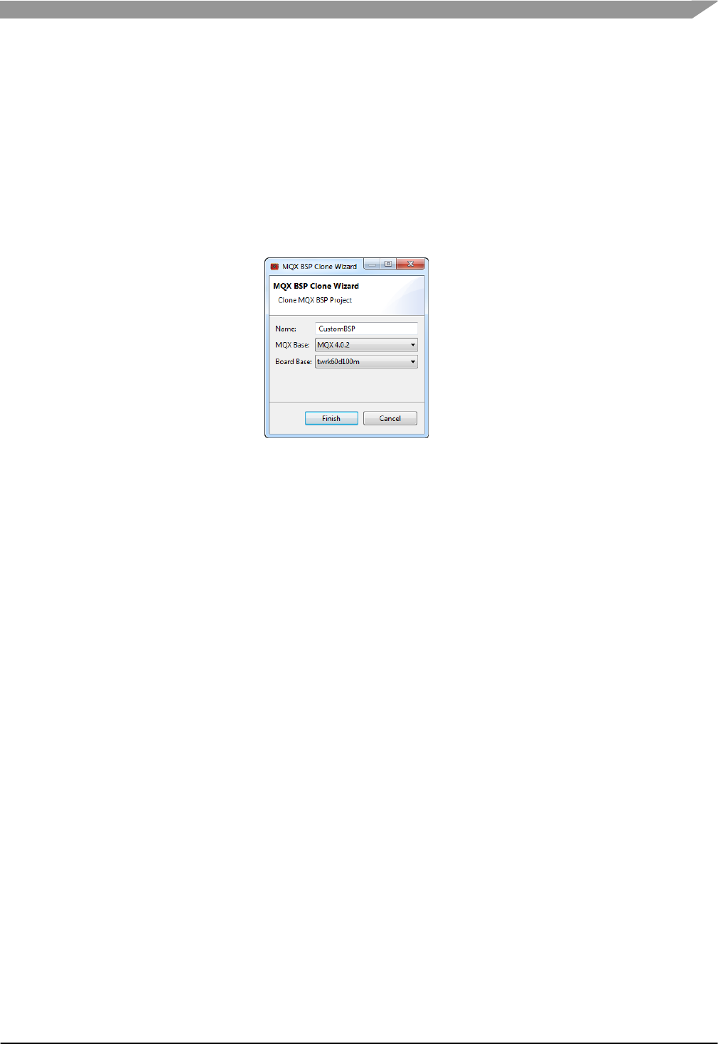
3 Cloning the BSP
For the Kinetis derivative MK40DX256VMD10, this example starts with the TWR-K60D100M MQX
BSP provided in the MQX release. Cloning is done with the BSP Cloning Wizard. The name for the
new clone is CustomBSP and the board base to clone is TWR-K60D100M. These steps modify
CustomBSP to port it to the TWR-K40D100M board.
Figure-1 BSP Cloning Wizard Settings
4 Using Processor Expert (PEx) in the BSP
Using PEx in the MQX BSP is optional. This section explains how to add PEx into a BSP project for
IAR or Keil. The CodeWarrior projects for the Kinetis MQX BSPs already include PEx support. The
projects are released with the PEx components included, but the PEx source code is not generated.
Building the projects as released does not use PEx. However, the PEx code can be easily
generated within the project and no user integration is required to include PEx in the BSP. Skip to
Section Changing the PEx Package to use PEx in a CodeWarrior BSP project.
4.1 Setting up BSP for PEx with IAR EW-ARM
Since MQX RTOS version 4.0.2, the BSP project did not include PEx support. These steps show
how to use the PEx Driver Suite and add PEx support to the BSP.
4.1.1 Adding PEx Driver Suite Project
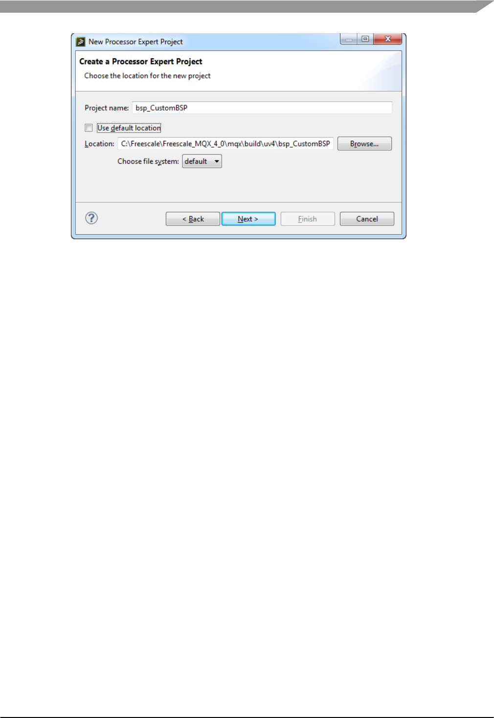
1. In PEx, create a new PEx project using the menu File->New->Processor Expert Project
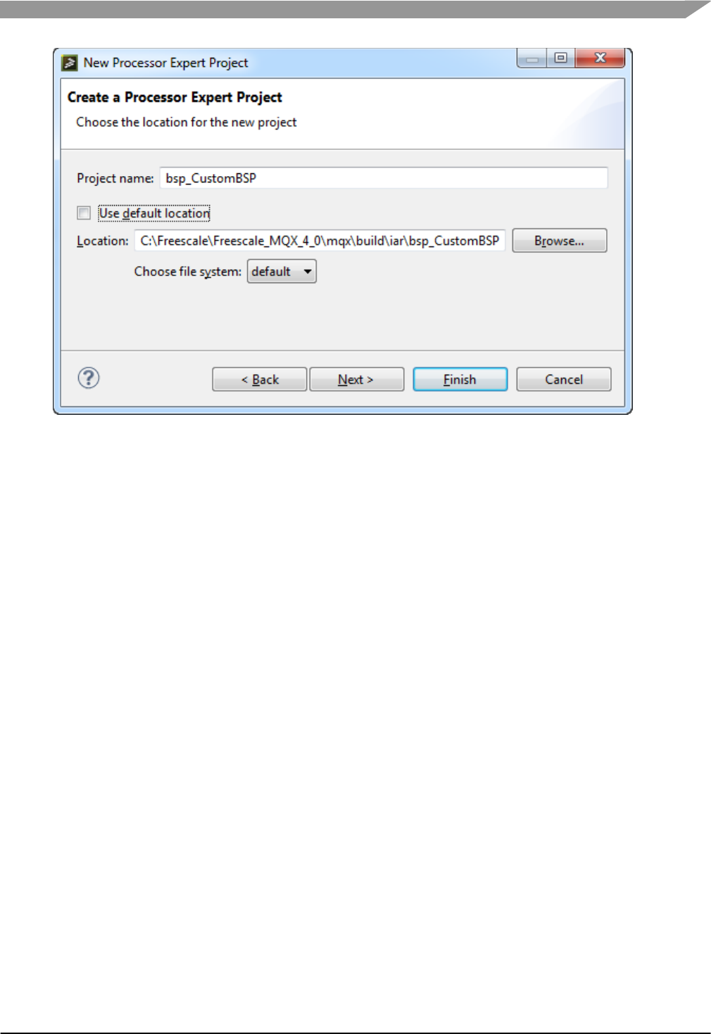
2. Name the project the same name as the BSP project, in this case bsp_CustomBSP
3. Do not use the default location. Instead, create the project in the BSP project directory for
IAR, in this case \mqx\build\iar\bsp_CustomBSP. Note that the tool defaults to creating a
subdirectory under bsp_CustomBSP with the same name. Be sure to correct the path so
that the PEx project is created in the same directory as the IAR project. The warning caused
by this is OK.
Freescale MQX™ RTOS BSP Porting Guide, Rev. 1, 11/2014
Freescale Semiconductor
4
Figure-2 New PEx BSP Project
4. Select the device for the original BSP, in this case MK60DN512xxx10. This device is
changed later.
5. Choose desired perspective. If unsure, use current perspective.
6. Select the IAR compiler and Finish.
4.1.2 Re-Use the PEx settings from CodeWarrior project
The CodeWarrior BSP project already has the CPU component setup for the cloned BSP. It’s
easiest to re-use that setup, and then modify as desired.
7. In PEx, close the bsp_CustomBSP project, by right-clicking on the project and select Close
Project.
8. Copy the ProcessorExpert.pe file from the CodeWarrior BSP project directory to the IAR
BSP project directory, overriding the file just created in the new project. In this case copy:
\mqx\build\cw10\bsp_CustomBSP\ProcessorExpert.pe
to
\mqx\build\iar\bsp_CustomBSP\ProcessorExpert.pe
9. Re-open the project in PEx by right-clicking the project and selecting Open Project.
10. Eclipse may give an error, such as Resource is out of sync with the file system. Right-
click the project and click Refresh.
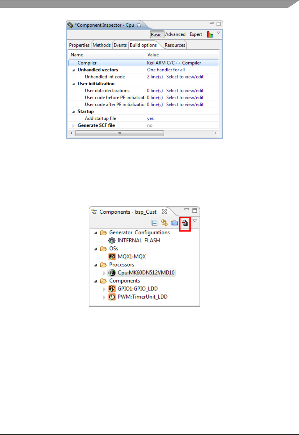
11. Copying the CodeWarrior file changed the compiler settings. To change it back, select the
CPU component in the Components View. In the Component Inspector, select the Build
options tab. Change the Compiler to IAR.
Freescale MQX™ RTOS BSP Porting Guide, Rev. 1, 11/2014
Freescale Semiconductor
5
Figure-3 Change compiler in PEx to IAR
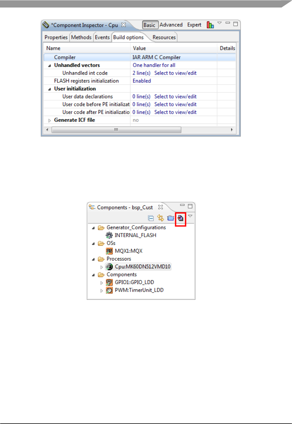
4.1.3 Generate the PEx code for the BSP
12. The file ProcessorExpert.c in the sources folder conflicts with MQX RTOS. Remove it from
the project by right-clicking on it and selecting Delete.
13. Click the Generate Code button.
Figure-4 Generate Code in PEx
4.1.4 Update the IAR BSP project to use PEx
IAR has a feature called Project Connection that allows IAR to import an XML file from PEx with
most of the project settings. However, as of EWARM v6.50.2, there are still several things to
manually change in the project.
14. Open the custom BSP workspace in IAR, in this case
\build\CustomBSP\iar\build_libs.eww
15. Be sure that the BSP project is the active project. If not bold, right-click on the project and
select Set as Active.
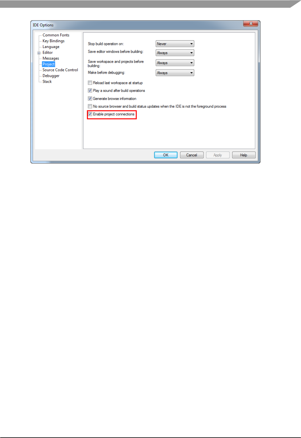
16. Enable Project Connections in IAR. Use the menu Tools->Options. Check the box Enable
Project Connects in the project options. Click OK to save.
Freescale MQX™ RTOS BSP Porting Guide, Rev. 1, 11/2014
Freescale Semiconductor
6
Figure-5 Enable Project Connections in IAR
17. Add a connection to PEx using the menu Project->Add Project Connection.
18. Connect using Freescale Processor Expert.
19. Browse to the ProjectInfo.xml file generated by PEx. In this case,
\mqx\build\iar\bsp_CustomBSP\ProjectInfo.xml. Click Open. This has added the source
files from PEx and the compiler paths to the project.
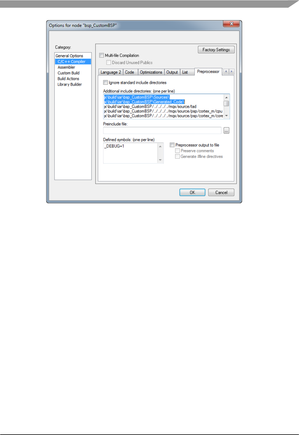
20. Update compiler search path ordering. PEx adds definitions and functions already included
in the BSP, so it is important to set up the toolchain to use the PEx generated code instead
of the existing files. Right-click the BSP project and select Options. The project connection
has already added the two paths below in the C/C++Compiler->Preprocessor settings.
They need to be moved to the top of the include directories to ensure that the compiler finds
the PEx headers first:
\mqx\build\iar\bsp_CustomBSP\Sources\
\mqx\build\iar\bsp_CustomBSP\Generated_Code\
Freescale MQX™ RTOS BSP Porting Guide, Rev. 1, 11/2014
Freescale Semiconductor
7
Figure-6 IAR BSP Preprocessor Setting Changes
4.1.5 Update IAR BSP Batch File for PEx
MQX RTOS uses batch files to copy the header files required by the applications to the lib folder.
The BSP batch file needs to be updated to copy the PEx files to the lib folder. The code from the
CodeWarrior section can be re-used.
21. Edit the BSP batch file, in this case \mqx\build\bat\bsp_CustomBSP.bat. Note that in
Windows, double-clicking on the batch file executes it. To edit it, right-click and select Edit.
22. Find the CodeWarrior section under the label :tool_cw10. Find the lines related to
%OUTPUTDIR%\Generated_Code and %OUTPUTDIR%\Sources and copy those lines.
23. Find the IAR section under the label :tool_iar. Paste the lines from above at the top of this
section.
24. Modify the paths. Replace cw10 with iar. Modify the filenames of the linker files. In this
example, the modified IAR section looks like this:
:tool_iar
IF NOT EXIST %OUTPUTDIR%\Generated_Code mkdir %OUTPUTDIR%\Generated_Code
for /R %MQXROOTDIR%\mqx\build\iar\bsp_CustomBSP\Generated_Code %%f in (*.h) do copy %%f
%OUTPUTDIR%\Generated_Code\
IF NOT EXIST %OUTPUTDIR%\Sources mkdir %OUTPUTDIR%\Sources
for /R %MQXROOTDIR%\mqx\build\iar\bsp_CustomBSP\Sources %%f in (*.h) do copy %%f
%OUTPUTDIR%\Sources\
copy %MQXROOTDIR%\mqx\source\bsp\CustomBSP\iar\intflash.icf %OUTPUTDIR%\intflash.icf /Y
copy %MQXROOTDIR%\mqx\source\bsp\CustomBSP\iar\ram.icf %OUTPUTDIR%\ram.icf /Y
goto copy_end
25. Save the batch file.
4.1.6 Build the MQX Libraries
Test the changes are correct by building all MQX libraries for the CustomBSP.
Freescale MQX™ RTOS BSP Porting Guide, Rev. 1, 11/2014
Freescale Semiconductor
8
26. If the BSP project has already been built, it may need to be cleaned for the changes to take
effect. Right-click the BSP project and select Clean.
27. Build the workspace using the menu Project->Batch Build. Select Debug, and hit the Make
button. There should be no errors in these project builds.
28. Verify that the PEx headers are included in the lib folder for the applications. Events.h
should be in the sources directory below, and there should be several files in the
Generated_Code directory. If these files are missing, check the batch file, save it, clean the
BSP, and rebuild it. In this case, the lib paths are:
\lib\CustomBSP.iar\debug\bsp\Generated_Code
\lib\CustomBSP.iar\debug\bsp\Sources
4.1.7 Test PEx changes with pe_demo
MQX RTOS provides an application demo to work with PEx in the BSP. These modifications to the
BSP can be tested using the pe_demo application. At this point, the MCU derivative has not been
changed from the original BSP. Therefore, the pe_demo can be run on the board associated with
the original BSP to test it, in this case the TWR-K60D100M board.
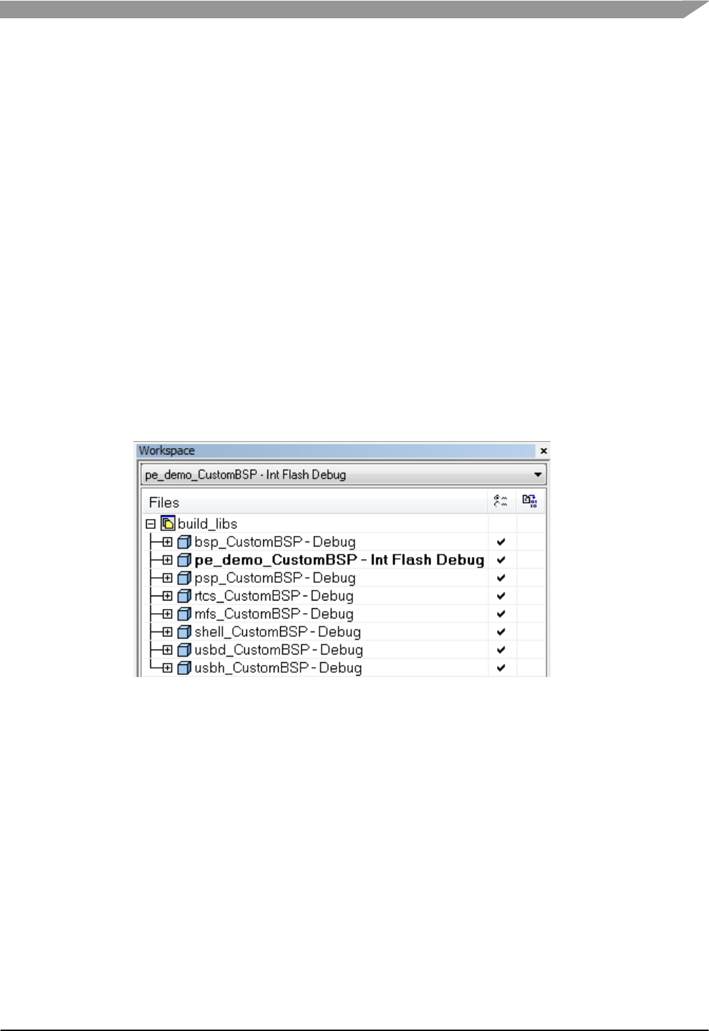
29. Add the pe_demo project to the IAR workspace. Use menu Project->Add Existing
Project. Browse to the pe_demo project for the custom BSP, in this case
\demo\pe_demo\iar\pe_demo_CustomBSP\pe_demo_CustomBSP.ewp. Click Open.
Figure-7 pe_demo project added to IAR workspace
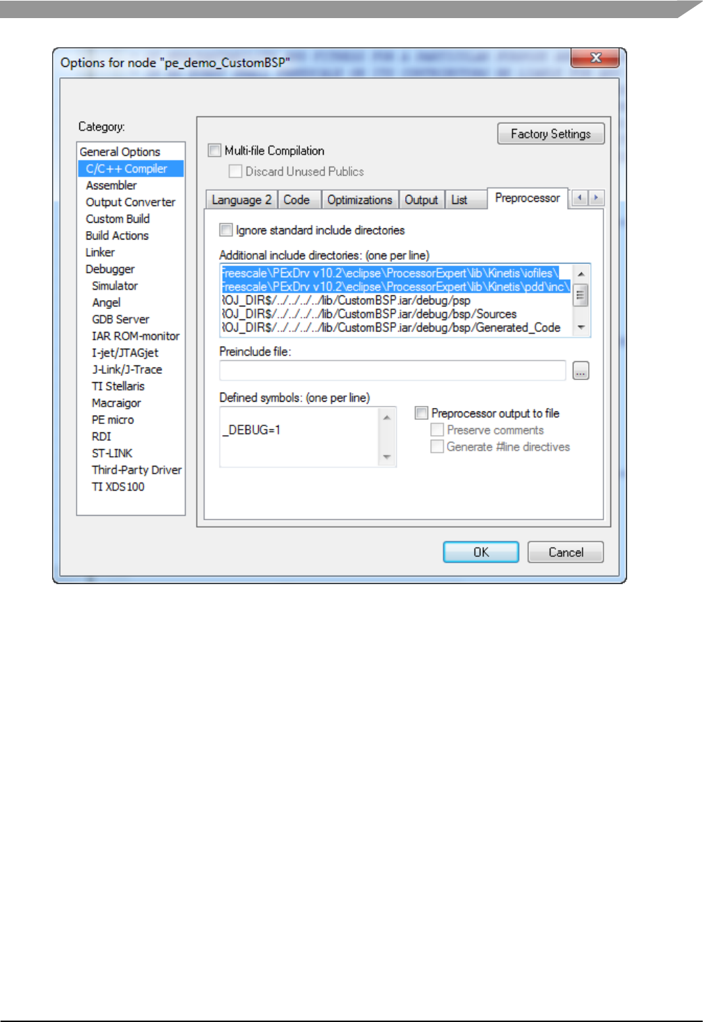
30. Add PEx header paths. The applications need two paths added that point to header files
located in the PEx Driver Suite installation. These two paths are already included in the BSP
project settings from the Project Connection. Copy the two paths below from the BSP project
and add to the pe_demo project settings in C/C++Compiler->Preprocessor, at the top of
the list. Click OK to save.
<PEx Driver Suite Installation>\eclipse\ProcessorExpert\lib\Kinetis\iofiles\
<PEx Driver Suite Installation>\eclipse\ProcessorExpert\lib\Kinetis\pdd\inc\
Freescale MQX™ RTOS BSP Porting Guide, Rev. 1, 11/2014
Freescale Semiconductor
9
Figure-8 PEx paths added to pe_demo in IAR
31. Build the pe_demo project. There should be no errors.
32. Download and test pe_demo on the board for the original BSP, in this case TWR-
K60D100M board.
4.2 Setting up BSP for PEx with Keil µVision®
As of MQX RTOS version 4.0.2, the BSP project did not include PEx support. These steps show
how to use the PEx Driver Suite and add PEx support to the BSP.
4.2.1 Adding PEx Driver Suite Project
1. In PEx, create a new PEx project using the menu File->New->Processor Expert Project
2. Name the project the same name as the BSP project, in this case bsp_CustomBSP
3. Do not use the default location, instead create the project in the BSP project directory for
Keil, in this case \mqx\build\uv4\bsp_CustomBSP. NOTE: the tool will default to creating a
subdirectory under bsp_CustomBSP with the same name. Be sure to correct the path so the
PEx project is created in the same directory as the Keil project. The warning caused by this
is OK.
Freescale MQX™ RTOS BSP Porting Guide, Rev. 1, 11/2014
Freescale Semiconductor
10
Figure-9 New PEx BSP Project for Keil
4. Select the device for the original BSP, in this case MK60DN512xxx10. This device will be
changed later.
5. Choose desired perspective, if unsure, use current perspective.
6. Select the Keil compiler and Finish.
4.2.2 Re-Use the PEx settings from CodeWarrior project
The CodeWarrior BSP project already has the CPU component setup for the cloned BSP. It’s
easiest to re-use that setup, and then modify as desired.
7. In PEx, close the bsp_CustomBSP project, by right-clicking on the project and select Close
Project.
8. Copy the ProcessorExpert.pe file from the CodeWarrior BSP project directory to the Keil
BSP project directory overriding the file just created in the new project. In this case copy:
\mqx\build\cw10\bsp_CustomBSP\ProcessorExpert.pe
to
\mqx\build\uv4\bsp_CustomBSP\ProcessorExpert.pe
9. Re-open the project in PEx by right-clicking the project and selecting Open Project.
10. Eclipse may give an error, such as Resource is out of sync with the file system. Right-
click the project and click Refresh.
11. Copying the CodeWarrior file changed the compiler settings. To change it back, select the
CPU component in the Components View. In the Component Inspector, select the Build
options tab. Change the compiler to Keil.
Freescale MQX™ RTOS BSP Porting Guide, Rev. 1, 11/2014
Freescale Semiconductor
11
Figure-10 Change compiler in PEx to Keil
4.2.3 Generate the PEx code for the BSP
12. The file ProcessorExpert.c in the Sources folder conflicts with MQX RTOS. Remove it from
the project by right-clicking on it, and select Delete.
13. Click the Generate Code button.
Figure-11 Generate Code in PEx
4.2.4 Update the Keil BSP project to use PEx
14. Open the custom BSP workspace in Keil, in this case
\build\CustomBSP\uv4\build_libs.uvmpw
15. Be sure that the BSP project is the active project. If not highlighted, right-click on the project
and select Set as Active Project.
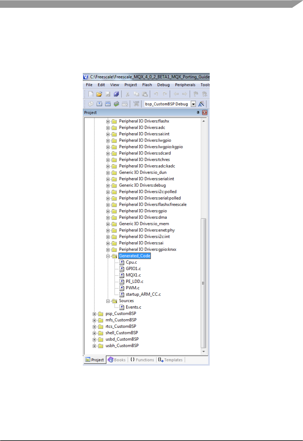
16. Add the PEx source files to the BSP project. Right-click the build configuration
bsp_CustomBSP Debug and select Add Group. Find New Group added to the bottom of
the list of groups in the project. Rename it by selecting, hit F2, and rename to
Generated_Code. Right-click on Generated_Code group and select Add files to group
Generated_Code. Navigate to the PEx Generated_Code directory, in this case
\mqx\build\uv4\bsp_CustomBSP\Generated_Code. Add all source files in this directory.
Freescale MQX™ RTOS BSP Porting Guide, Rev. 1, 11/2014
Freescale Semiconductor
12
17. Navigate to the directory
\mqx\build\uv4\bsp_CustomBSP\Project_Settings\Startup_Code and add the source file
startup_ARM_CC.c. Then click the Close button.
18. Repeat the steps above to add the group Sources, and add the file Events.c in the directory
\mqx\build\uv4\bsp_CustomBSP\Sources.
Figure-12 PEx source files added to Keil BSP project
19. Open the ProjectInfo.xml file. PEx generates an XML file with the files and paths used by
PEx to be added to the tool chain project. For Keil, it can be a useful reference to find the
paths required. In this case, use a text editor to open the file
\mqx\build\uv4\bsp_CustomBSP\ProjectInfo.xml.
20. Copy the PEx include paths. There are two paths used by PEx header files. These paths
need to be added to the compiler include paths. In ProjectInfo.xml, find these two include
Freescale MQX™ RTOS BSP Porting Guide, Rev. 1, 11/2014
Freescale Semiconductor
13
paths:
<PEx Driver Suite Installation>\eclipse\ProcessorExpert\lib\Kinetis\iofiles\
<PEx Driver Suite Installation>\eclipse\ProcessorExpert\lib\Kinetis\pdd\inc\
21. Modify the Keil compiler include paths. In Keil, open the options for the BSP project. Right-
click the build configuration bsp_CustomBSP Debug, select Options for
bsp_CustomBSP. Click the C/C++ tab. Place the cursor at the beginning of the Include
Paths field. Copy and paste the two paths in the step above from the XML file into the
include paths in Keil. Place a semicolon after each path. NOTE: be sure that these paths
contain no spaces.
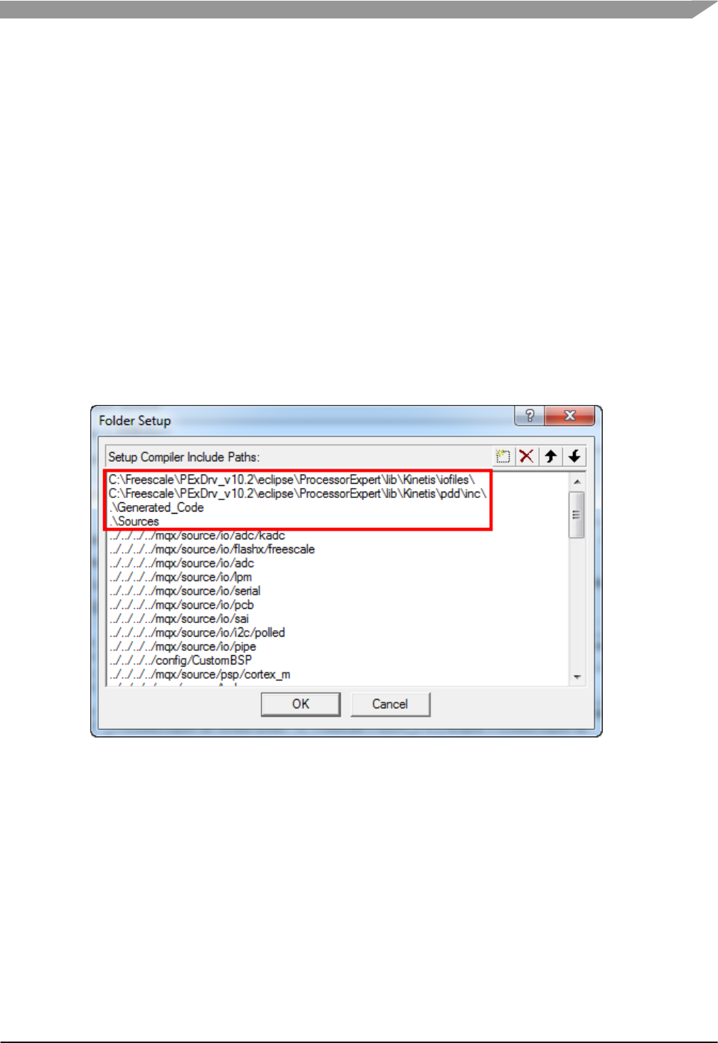
22. Add the PEx generated header file paths to the project. After the include paths added in the
step above, add these include paths with semicolons after each path. In this case, the four
paths to copy to the Include Paths field are like this:
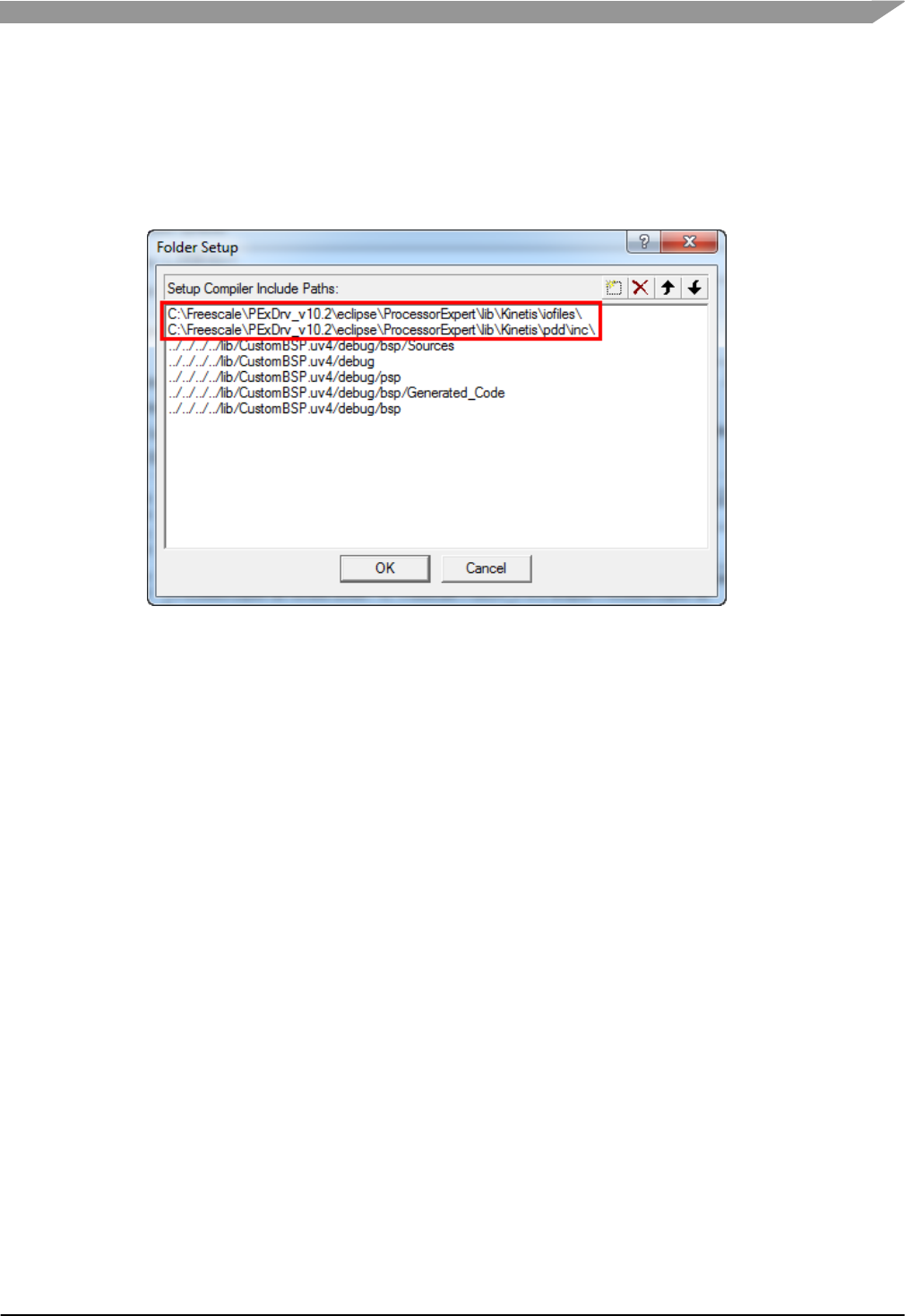
C:\Freescale\PExDrv_v10.2\eclipse\ProcessorExpert\lib\Kinetis\iofiles\;C:\Freescale\P
ExDrv_v10.2\eclipse\ProcessorExpert\lib\Kinetis\pdd\inc\;.\Generated_Code;.\
Sources;
23. Verify the include paths. Click the browse button to the right of the Include Paths field. The
PEx paths should be first in the list, similar to this image:
Figure-13 PEx include paths added to Keil
24. Click the OK button twice to save the project settings.
4.2.5 Update Keil BSP Batch File for PEx
MQX RTOS uses batch files to copy the header files required by the applications to the lib folder.
The BSP batch file needs to be updated to copy the PEx files to the lib folder. The code from the
CodeWarrior section can be re-used.
25. Edit the BSP batch file, in this case \mqx\build\bat\bsp_CustomBSP.bat. Note that in
Windows double-clicking on the batch file executes it. To edit it, right-click and select Edit.
26. Find the CodeWarrior section under the label :tool_cw10. Find the lines related to
%OUTPUTDIR%\Generated_Code and %OUTPUTDIR%\Sources, and copy those lines.
27. Find the Keil section under the label :tool_uv4. Paste the lines from above at the top of this
section.
Freescale MQX™ RTOS BSP Porting Guide, Rev. 1, 11/2014
Freescale Semiconductor
14
28. Modify the paths. Replace cw10 with uv4. Modify the filenames of the linker files. In this
example, the modified Keil section looks like this:
:tool_uv4
IF NOT EXIST %OUTPUTDIR%\Generated_Code mkdir %OUTPUTDIR%\Generated_Code
for /R %MQXROOTDIR%\mqx\build\uv4\bsp_CustomBSP\Generated_Code %%f in (*.h) do copy %%f
%OUTPUTDIR%\Generated_Code\
IF NOT EXIST %OUTPUTDIR%\Sources mkdir %OUTPUTDIR%\Sources
for /R %MQXROOTDIR%\mqx\build\uv4\bsp_CustomBSP\Sources %%f in (*.h) do copy %%f
%OUTPUTDIR%\Sources\
copy %MQXROOTDIR%\mqx\source\bsp\CustomBSP\uv4\intflash.scf %OUTPUTDIR%\intflash.scf /Y
goto copy_end
29. Save the batch file.
4.2.6 Build the MQX Libraries
Test the changes are correct by building all MQX libraries for the CustomBSP.
30. If the BSP project has already been built, it may need to be cleaned for the changes to take
effect. Use the menu Project->Clean bsp_CustomBSP(bsp_CustomBSP Debug).
31. Build the workspace using the menu Project->Batch Build. In this case, only the Debug
build targets need to be built.
32. Verify the PEx headers are included in the lib folder for the applications. Events.h should be
in the Sources directory, and there should be several files in the Generated_Code directory.
If these files are missing, check the batch file, save it, clean the BSP, and rebuild it. In this
case, the lib paths are:
\lib\CustomBSP.uv4\debug\bsp\Generated_Code
\lib\CustomBSP.uv4\debug\bsp\Sources
4.2.7 Test PEx changes with pe_demo
MQX RTOS provides an application demo to work with PEx in the BSP. These modifications to the
BSP can be tested using the pe_demo application. At this point, the MCU derivative has not been
changed from the original BSP. Therefore, the pe_demo can run on the board associated with the
original BSP to test it, in this case the TWR-K60D100M board.
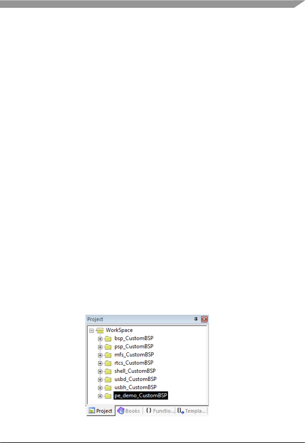
33. Add the pe_demo project to the Keil workspace. Use the menu Project->Manage->Multi-
Project Workspace. Click the New button. Browse to the pe_demo project for the custom
BSP, in this case
\demo\pe_demo\uv4\pe_demo_CustomBSP\pe_demo_CustomBSP.uvproj. Click Open.
Click OK to save the workspace.
Figure-14 pe_demo project added to Keil workspace
Freescale MQX™ RTOS BSP Porting Guide, Rev. 1, 11/2014
Freescale Semiconductor
15
34. Add PEx header paths. The applications will need two paths added that point to header files
located in the PEx Driver Suite installation. These are the same paths added earlier to the
BSP. Copy the two paths from the BSP project and add to the pe_demo project in the
compiler Include Paths. Click OK twice to save.
<PEx Driver Suite Installation>\eclipse\ProcessorExpert\lib\Kinetis\iofiles\
<PEx Driver Suite Installation>\eclipse\ProcessorExpert\lib\Kinetis\pdd\inc\
Figure-15 PEx paths added to pe_demo in Keil
35. Build the pe_demo project. There should be no errors.
36. Download and test pe_demo on the board for the original BSP, in this case TWR-
K60D100M board.
5 Changing MCU derivative in MQX projects
If the device used in the customized BSP is different than the original BSP, the MCU derivative
needs to be changed.
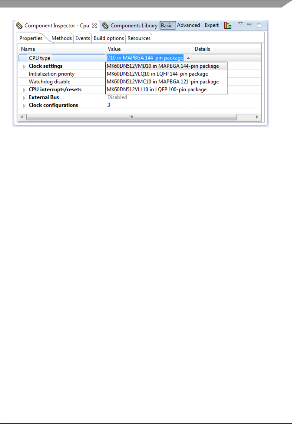
5.1 Changing the PEx Package
If PEx is used, PEx may be able to change the package instead of the CPU Component. This
minimizes the steps in using PEx with the BSP because the original BSP CPU properties are
preserved. To change the package, select the CPU Component in the Components View. In the
Component Inspector, under the Properties Tab, select the CPU type property. The available
packages for that device are shown. If the desired part number is not available, the CPU
Component needs to be changed, detailed in the next section.
Freescale MQX™ RTOS BSP Porting Guide, Rev. 1, 11/2014
Freescale Semiconductor
16
Figure-16 Changing Package in PEx
5.2 Changing the PEx CPU Component
If PEx is used, these steps describe changing the MCU derivative in the MQX BSP. In addition,
these documents installed with MQX RTOS have further details about managing the BSP project
with PEx.
How-to Change Default Clock Settings in Kinetis BSPs located in \doc\tools\cw.
CW for Microcontrollers V10 and MQX™RTOS, located in:
doc\tools\cw\MQX_CW10_Getting_Started.pdf (Windows menu: Tools
Documentation \CodeWarrior\Getting Started CW for Microcontrollers v10.x and
MQX).
Unfortunately, this step loses the CPU settings from the original CPU component. Use the original
CPU component as a reference.
1. Open the PEx BSP project.
Freescale MQX™ RTOS BSP Porting Guide, Rev. 1, 11/2014
Freescale Semiconductor
17
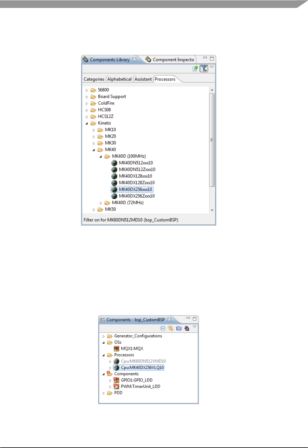
2. Add a new CPU component. In the Component Library View, under the Processors Tab,
navigate to the new CPU. In this case, MK40DX256xxx10. Double-click the component to
add to the project.
Figure-17 New CPU component in Components Library
3. Select the desired package, in this case MK40DX256VMD10 144-pin MAPBGA. The CPU
configurations are not important in this project since MQX RTOS doesn’t use PEx to
generate the linker command files. Click Next.
4. Select the desired compiler. Click Finish.
5. The new CPU component is added to the project and the old one is still present but disabled.
The old component’s settings can still be viewed for guidance on setting up the new
component.
Figure-18 New CPU Component in BSP project
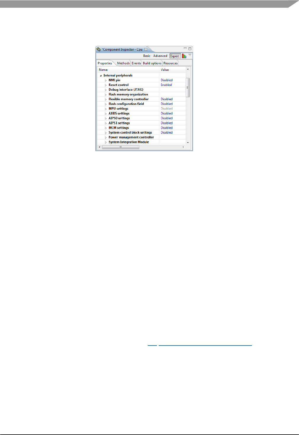
6. Change the internal peripheral settings. To avoid conflicts with MQX source code, some
features setup by PEx should be disabled. In the Component Inspector View, under the
Freescale MQX™ RTOS BSP Porting Guide, Rev. 1, 11/2014
Freescale Semiconductor
18
Properties Tab, expand the Internal Peripherals group. Disable the NMI pin and Flash
Configuration properties:
Figure-19 PEx Internal Peripheral Settings
7. The existing peripheral components may have errors after the CPU change, caused by
changes in pin names and clock frequencies. Clean up the errors, or remove the
unnecessary components. In this case, fix the counter frequency of the PWM component if
needed, and change the pins used in the GPIO1 component as shown in this list:
LED1 PTC7
LED2 PTC8
LED3 PTC9
LED4 PTC11
8. Generate the PEx code.
5.3 Specify MCU derivative in MQX RTOS
MQX RTOS uses macros for the MCU derivative, board specifics, and derivative header files.
9. Find driver files dependent on the MCU derivative. User_config.h uses the macro
MQX_CPU to define the derivative in the BSP. In this case, the derivative is defined as
PSP_CPU_MK60D100M. The file \mqx\source\psp\cortex_m\kinetis.h uses this
derivative to include the correct header file. In this case, the header file is
\mqx\source\psp\cortex_m\cpu\MK60D10.h. The top of this header file defines an MCU
derivative, in this case MCU_MK60D10. Search the BSP project to find driver files that
reference this macro and make a note of these files because they may need to be modified
after the derivative is changed (see Section 5.4 Modifying Driver Derivative Files). In this
case, there is one driver file below that references MCU_MK60D10:
\mqx\source\io\sai\sai_mk60.c
10. Modify MCU derivative in user_config.h. MQX RTOS already has a list of several supported
derivatives in \Freescale_MQX_4_0\mqx\source\psp\cortex_m\kinetis.h. Find the
derivative macro for the customized BSP and update user_config.h with this derivative. In
this case, the line below in user_config.h is modified for the desired K40:
#define MQX_CPU PSP_CPU_MK40DX256
Freescale MQX™ RTOS BSP Porting Guide, Rev. 1, 11/2014
Freescale Semiconductor
19
11. If the desired derivative is not in the list in kinetis.h, it can be added. An example is the
device MK20DN512VLK10. A BSP for this derivative can also be cloned from TWR-
K60D100M, but the MQX release has no support for this derivative. In this case, the lines
below are added to kinetis.h:
#elif (MQX_CPU == PSP_CPU_MK20DN512)
#include "MK20D10.h"
12. If the desired derivative header file is missing from the MQX release, add it. Find the desired
header file in the toolchain directory listed below. Copy the header file to
\mqx\source\psp\cortex_m\cpu.
<CodeWarrior Installation>\MCU\lib\wizard_data\ARM\DataBase\derivatives
IAR: <IAR Installation>\arm\inc\Freescale
Keil: <Keil Installation>\ARM\INC\Freescale\Kinetis
13. Update the PSP batch file if the derivative header file is changed. In this example, modify the
batch file found at \mqx\build\bat\psp_CustomBSP.bat:
copy %MQXROOTDIR%\mqx\source\psp\cortex_m\cpu\MK40D10.h %OUTPUTDIR%\MK40D10.h /Y
14. If the PSP_CPU_ macro used in user_config.h was newly added to kinetis.h, there is one
more step to define the new macro. Edit \mqx\source\psp\cortex_m\psp_cpudef.h and
add a new entry for the new CPU Identification macro, like this:
#define PSP_CPU_MK20DN512 (PSP_CPU_NUM(PSP_CPU_ARCH_ARM_CORTEX_M4,
PSP_CPU_GROUP_KINETIS_K2X, 0xE))
5.4 Modifying Driver Derivative Files
15. Review the derivative specific driver source files for the desired derivative. If needed, modify
the files, or change the BSP project to use a different source file for the desired sub-family.
In this case, the source files used in the BSP are changed as follows:
\mqx\source\io\sai\sai_mk40.c instead of sai_mk60.c
6 Clock Configuration
In this example, the BSP needs the clock source changed from a 50 MHz oscillator to an 8 MHz
crystal. Also, the example changes the PLL output from 96 MHz to 48 MHz, to force a change to
the USB clock dividers, and detail these steps.
6.1 Changing Clock Configuration with PEx
These steps assume PEx is already included in the BSP project, see Using Processor Expert (PEx)
in the BSP.
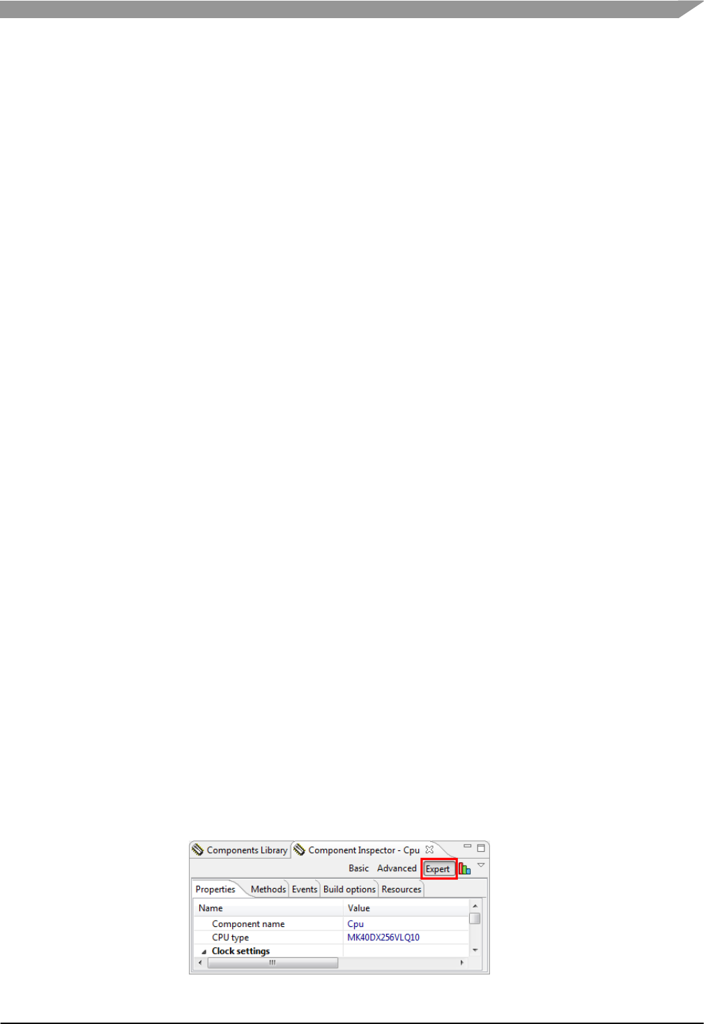
Figure-20 Expert Mode in Component Inspector
Freescale MQX™ RTOS BSP Porting Guide, Rev. 1, 11/2014
Freescale Semiconductor
20
It is recommended to use Expert mode in the Component Inspector to see all property options for
the PEx component. To use Expert mode, click the Expert button in the upper right corner of the
Component Inspector View.
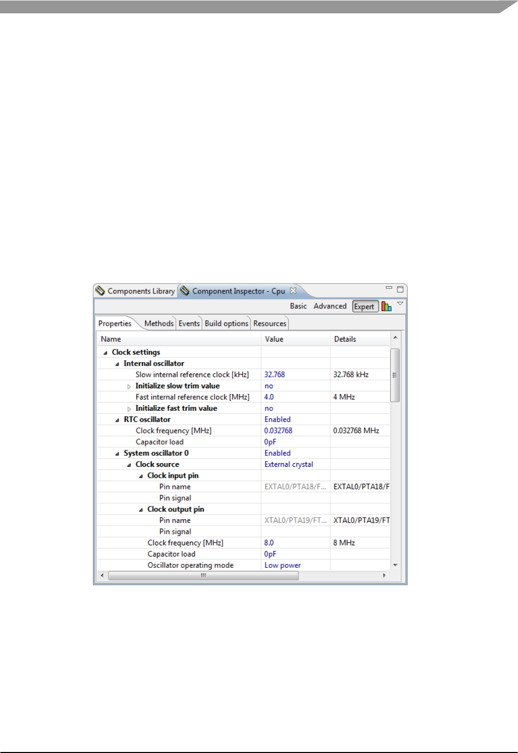
6.1.1 Configure the Clock Settings
Use the Component Inspector View to configure the CPU component. Expand the Clock Settings
properties group.
1. Internal Oscillator: these settings generally do not need to be changed. This example leaves
them in their default settings.
2. RTC Oscillator: If the BSP uses the RTC peripheral with the 32 kHz oscillator, this oscillator
needs to be enabled. In this example, the TWR-K40D100M board includes a 32 kHz crystal,
and the RTC oscillator is enabled with no load capacitors added.
3. System Oscillator 0: this should be enabled and configured if any external clock source is
used. In this example, the BSP requires an external clock source for USB. The TWR-
K40D100M board uses an 8 MHz crystal. No load capacitors are added and set oscillator
operating mode to Low Power.
Figure-21 PEx Clock Settings
4. Clock Source Settings: the Kinetis BSPs in MQX RTOS are enabled for low-power modes.
To enable this, there are generally two Clock Source Settings. The first is for Run mode with
the clock frequencies running at their maximum for the BSP. The second is for VLPR mode,
running from the internal fast oscillator. In this example, the BSP uses these two Clock
Source Settings. Change the number of Clock Source Settings to 2.
Freescale MQX™ RTOS BSP Porting Guide, Rev. 1, 11/2014
Freescale Semiconductor
21
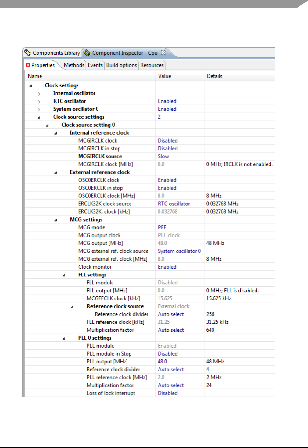
5. Clock Source Setting 0: this is the setting for RUN mode. In this example, it uses the 8 MHz
crystal. Use the MCG in PEE mode to multiply the PLL Output clock up to 48 MHz.
Figure-22 PEx Clock Source Setting 0
Freescale MQX™ RTOS BSP Porting Guide, Rev. 1, 11/2014
Freescale Semiconductor
22
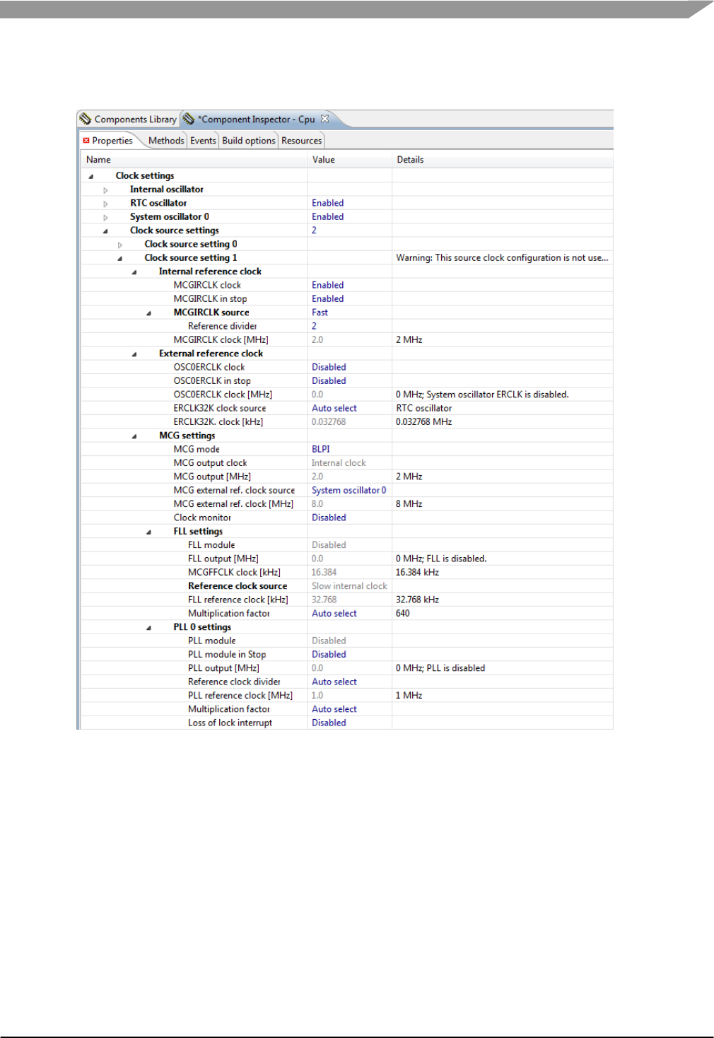
6. Clock Source Setting 1: this is the setting for the VLPR low-power mode. In this example, it
uses the fast internal oscillator in BLPI mode with a 2 MHz output clock from the MCG.
Figure-23 PEx Clock Source Setting 1
6.1.2 Clock Configurations
PEx allows for multiple clock configurations to dynamically change the clock settings. The MQX
BSP takes advantage of this for low-power optimizations. In this example, the BSP uses 3 Clock
Configurations.
7. Set the number of Clock Configurations to 3.
Freescale MQX™ RTOS BSP Porting Guide, Rev. 1, 11/2014
Freescale Semiconductor
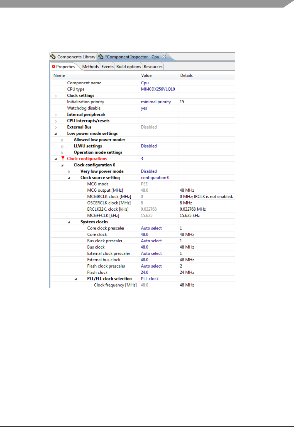
23
8. Clock Configuration 0: this is the main configuration for RUN mode, setting the Core Clock to
48 MHz, peripheral Bus Clock to 48 MHz, External Bus Clock to 48 MHz, and Flash Clock to
24 MHz using the PLL Clock.
Figure-24 PEx Clock Configuration 0
Freescale MQX™ RTOS BSP Porting Guide, Rev. 1, 11/2014
Freescale Semiconductor
24
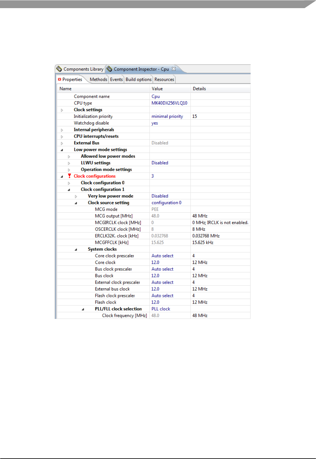
9. Clock Configuration 1: this configuration is used for the MCGAutoTrim method, which
requires the Peripheral Bus Clock to be in that range of 8-16 MHz. This configuration uses
the PLL Clock, and sets the Core Clock, Peripheral Bus Clock, External Bus Clock, and
Flash Clock all to 12 MHz.
Figure-25 PEx Clock Configuration 1
Freescale MQX™ RTOS BSP Porting Guide, Rev. 1, 11/2014
Freescale Semiconductor
25
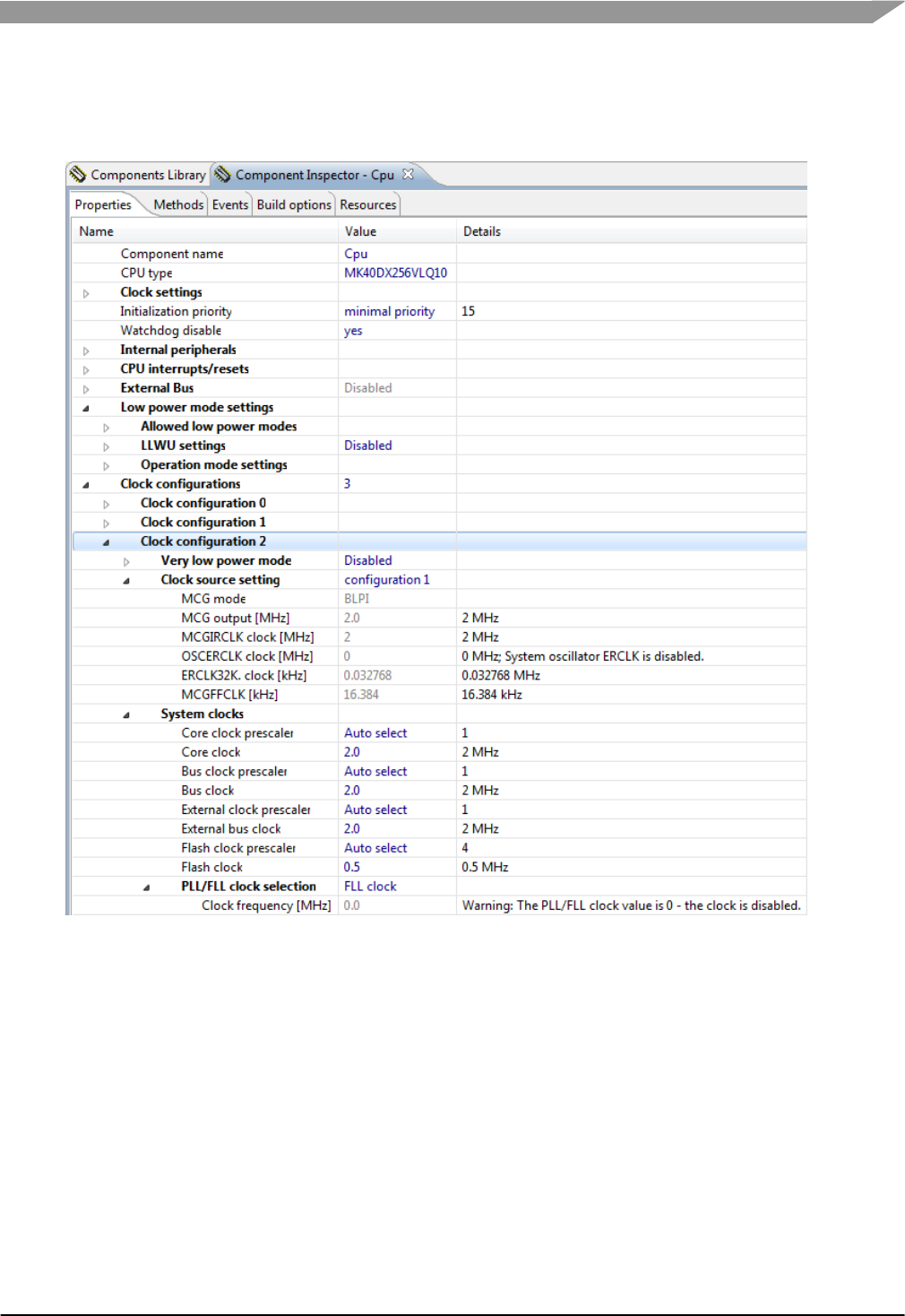
10. Clock Configuration 2: this configuration is used when running in VLPR mode. It uses the
Clock Source Setting 1 setup previously and sets the Core Clock, Peripheral Bus Clock, and
External Bus Clock all to 2 MHz, with the Flash Clock set to 0.5 MHz.
Figure-26 PEx Clock Configuration 2
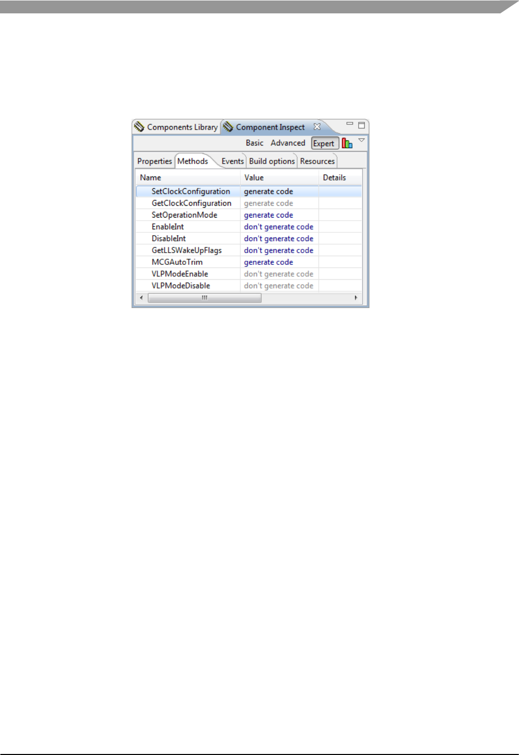
6.1.3 PEx CPU Component Methods
By default, the BSP uses two methods generated by PEx. The first method
CPU_SetOperationMode is used by the LPM driver to change low-power operating modes. The
second method CPU_MCGAutoTrim is used to trim the internal reference clock. In this example,
PEx generates both methods.
11. Click the Methods tab at the top of the Component Inspector.
12. Generate Code for the SetOperationMode method. Note that this is only required if using
the LPM driver for low-power modes and the macro MQX_ENABLE_LOW_POWER is set.
By default, this macro is not set, and the libraries should build without the
SetOperationMode method generated.
Freescale MQX™ RTOS BSP Porting Guide, Rev. 1, 11/2014
Freescale Semiconductor
26
13. Generate Code for the MCGAutoTrim method. Note that this method requires a clock
configuration to have the Peripheral Bus Clock set in the range of 8-16 MHz and derived
from an external clock source. In this example, Clock Configuration 1 was created to meet
these requirements in the previous steps. If this method is not desired, remove the call to
_bsp_osc_autotrim() in _bsp_pre_init() in \mqx\source\bsp\CustomBSP\init_bsp.c.
Figure-27 PEx Methods for CPU Component
6.1.4 Generate PEx Code
14. Clean up any errors in other PEx components if needed. If the PWM component is still
included, change the counter frequency to 48 MHz to eliminate those errors.
15. Generate the PEx code.
6.2 Changing Clock Configuration without PEx
If PEx is not used in the BSP, the source files with the clock configuration need to be modified
manually. PEx can still be used for this, even if PEx is not included in the BSP project. PEx can be
used to create a new project, configure the clocks as desired, and then the generated source code
can be copied from PEx into the MQX source files. Alternatively, the files below can be modified
manually without PEx.
1. bsp_cm.c: modify the functions with the prefix CPU_ and __bsp_initialize_hardware()
(called __pe_initialize_hardware() by PEx in Cpu.c) in bsp_cm.c. This requires modifying
the MCG peripheral registers for the desired clock configurations. See a device reference
manual and the Kinetis Quick Reference User Guide (document KQRUG) in Chapter 4 for
help on configuring the MCG.
2. bsp_cm.h: the macros with the prefix CPU_ need to be modified with the values for the
desired clock configurations (these come from CPU.h from PEx).
3. bsp_cm.h: the enumeration BSP_CLOCK_CONFIGURATION needs to be updated with the
desired clock configurations. In this example, BSP_CLOCK_CONFIGURATION_96MHZ is
renamed to BSP_CLOCK_CONFIGURATION_48MHZ. All references to this name in the
BSP project need to be updated. There is only one reference in
\mqx\source\bsp\CustomBSP\CustomBSP.h.

Freescale MQX™ RTOS BSP Porting Guide, Rev. 1, 11/2014
Freescale Semiconductor
27
7 BSP include files
The following header files in \mqx\source\bsp\CustomBSP are modified.
7.1 <Board_Name>.h File
In this example, this file is \mqx\source\bsp\CustomBSP\CustomBSP.h.
7.1.1 Board Type
CustomBSP.h file includes a Board Type definition, in this case BSP_TWR_K60D100M. This
macro is used for hardware specific code in the drivers and BSP startup code, similar to the MCU
derivative macro.
1. Search the BSP library projects for this Board Type macro to see where it is used. Those
files may need to be modified if this macro is changed. In this case, BSP_TWR_K60D100M
is only referenced in one file, \mqx\source\io\enet\macnet\macnet_1588.c, which is used
for initializing the Ethernet MAC, which will not be used in the K40 CustomBSP.
2. Change the Board Type macro to a new name for the customized BSP, in this case
BSP_CUSTOMBSP.
7.1.2 MCU Memory Map
3. Review the memory map symbols and change as needed for the specific MCU derivative
and board.
4. In this case, the program flash size and the internal SRAM in the K40 derivative is half the
size of the K60 derivative in the original BSP. These lines are modified to account for the
changes in flash and SRAM size:
#define BSP_INTERNAL_FLASH_SIZE 0x00040000
#define __FLASHX_START_ADDR 0x00030000
#define __FLASHX_END_ADDR 0x00040000
#define __VECTOR_TABLE_RAM_START 0x1FFF8000
5. The K40 derivative in this example includes FlexMemory, which is not in the K60 derivative
from the original BSP. The macros are added to this file to define the FlexMemory address
range
Within the section for the Keil compiler inside the #ifdef __CC_ARM:
#define __INTERNAL_FLEXNVM_BASE 0x10000000
#define __INTERNAL_FLEXNVM_SIZE 0x00040000
#define __INTERNAL_FLEXRAM_BASE 0x14000000
#define __INTERNAL_FLEXRAM_SIZE 0x00001000
6. Within the else section for all other tool chains:
extern uchar __INTERNAL_FLEXRAM_BASE[];
extern uchar __INTERNAL_FLEXRAM_SIZE[];
7. Outside that section for all tool chains:
#define BSP_INTERNAL_FLEXRAM_BASE ((pointer)__INTERNAL_FLEXRAM_BASE)
#define BSP_INTERNAL_FLEXRAM_SIZE ((_mem_size)__INTERNAL_FLEXRAM_SIZE)
#define BSP_INTERNAL_FLEXRAM_BASE_ADDRESS 0x14000000
7.1.3 Clock Configuration Changes
See Section 6 Clock Configuration for changes done in previous steps.

Freescale MQX™ RTOS BSP Porting Guide, Rev. 1, 11/2014
Freescale Semiconductor
28
7.1.4 GPIO Board Specifications
8. This file defines several macros specifying which GPIO pins are used for the features on the
board, including the LEDs, and input switches. In this example, these lines are modified for
the GPIO signals used on the TWR-K40D100M board:
#define BSP_LED1 (GPIO_PORT_C | GPIO_PIN7)
#define BSP_LED2 (GPIO_PORT_C | GPIO_PIN8)
#define BSP_LED3 (GPIO_PORT_C | GPIO_PIN9)
#define BSP_LED4 (GPIO_PORT_B | GPIO_PIN11)
#define BSP_SW1 (GPIO_PORT_C | GPIO_PIN5)
#define BSP_SW2 (GPIO_PORT_C | GPIO_PIN13)
#define BSP_ACCEL_IRQ (GPIO_PORT_C | GPIO_PIN12) /* onboard accel. IRQ pin */
#define BSP_LED1_MUX_GPIO (LWGPIO_MUX_C7_GPIO)
#define BSP_LED2_MUX_GPIO (LWGPIO_MUX_C8_GPIO)
#define BSP_LED3_MUX_GPIO (LWGPIO_MUX_C9_GPIO)
#define BSP_LED4_MUX_GPIO (LWGPIO_MUX_B11_GPIO)
#define BSP_SW1_MUX_GPIO (LWGPIO_MUX_C5_GPIO)
#define BSP_SW2_MUX_GPIO (LWGPIO_MUX_C13_GPIO)
#define BSP_ACCEL_MUX_GPIO (LWGPIO_MUX_C12_GPIO)
#define BSP_LCD_NAVSW_N (GPIO_PORT_C | GPIO_PIN18)
#define BSP_LCD_NAVSW_W (GPIO_PORT_A | GPIO_PIN16) /* open J4 1-2 */
#define BSP_LCD_NAVSW_E (GPIO_PORT_E | GPIO_PIN5)
#define BSP_LCD_NAVSW_S (GPIO_PORT_C | GPIO_PIN19)
#define BSP_LCD_NAVSW_CTR (GPIO_PORT_E | GPIO_PIN27)
#define BSP_LCD_DC (GPIO_PORT_A | GPIO_PIN9) /* open J14 15-16 */
#define BSP_LCD_DC_FN 1 /* LCD DC pin */
#define BSP_LCD_TCHRES_X_PLUS (GPIO_PORT_B | GPIO_PIN3) /* open J7 7-8 */
#define BSP_LCD_TCHRES_X_MINUS (GPIO_PORT_B | GPIO_PIN1) /* open J7 5-6 */
#define BSP_LCD_TCHRES_Y_PLUS (GPIO_PORT_B | GPIO_PIN0) /* open J7 3-4 */
#define BSP_LCD_TCHRES_Y_MINUS (GPIO_PORT_B | GPIO_PIN2) /* open J7 7-8 */
#define BSP_LCD_SPI_CHANNEL "spi0:"
#define BSP_LCD_X_PLUS_ADC_CHANNEL (ADC0_SOURCE_AD13)
#define BSP_LCD_Y_PLUS_ADC_CHANNEL (ADC0_SOURCE_AD8)
#define BSP_TCHRES_ADC_DEVICE "adc0:"
#define BSP_TCHRES_X_TRIGGER ADC_PDB_TRIGGER
#define BSP_TCHRES_Y_TRIGGER ADC_PDB_TRIGGER
7.1.5 I/O Driver Default Options
Many of the drivers use macros defined in this file for the default options. These options should all
be reviewed when customizing the BSP. These steps include some key changes for this example:
9. Ethernet Driver Options. The K40 does not include the Ethernet MAC like the K60 used in
the original BSP. The line below is changed to remove the ENET driver from the BSP. Also,
all other macros with the text “ENET”, “MACNET”, “BSPCFG_RX”, “BSPCFG_TX” are
removed.
#define BSP_ENET_DEVICE_COUNT 0
10. The SD Card detect pin is changed using the lines below. The Write Protect pin remains the
same.
#define BSP_SDCARD_GPIO_DETECT (GPIO_PORT_A | GPIO_PIN16)
#define BSP_SDCARD_DETECT_MUX_GPIO (LWGPIO_MUX_A16_GPIO)
11. ADC channel for ADC example. The TWR-K40D100M board has a potentiometer on the
board for evaluating the ADC. The schematic shows the potentiometer is connected to the
signal ADC1_DM1. The K40 Reference Manual includes an ADC section in the Chip
Configuration Chapter 3. The table for ADC1 Channel Assignment shows that for a single-
ended ADC conversion on signal ADC1_DM1, the ADC1 should be set to use channel
AD20. Therefore, the BSP uses the macro below. This does not need to change from the
K60 BSP.
#define BSP_ADC_CH_POT (ADC1_SOURCE_AD20)

Freescale MQX™ RTOS BSP Porting Guide, Rev. 1, 11/2014
Freescale Semiconductor
29
12. FlexNVM example. To enable the FlexNVM example for this BSP, these lines are added:
#define BSP_EE_DATA_SIZE_CODE (FLEXNVM_EE_SPLIT_1_1 | FLEXNVM_EE_SIZE_4096)
#define BSP_FLEXNVM_PART_CODE (FLEXNVM_PART_CODE_DATA128_EE128)
13. Segment LCD Driver. This macro is added to the file to enable the Segment LCD driver for
the K40:
#ifndef BSPCFG_ENABLE_LCD
#define BSPCFG_ENABLE_LCD 1
#endif
7.1.6 Default MQX Initialization
When MQX RTOS is initialized, it uses some default settings that are including in <Board_Name>.h
file.
14. Default I/O Channel. This defines which driver is used for the default I/O (printf()). In this
example, the lines below are modified to use UART0 with the TTYA driver.
#if BSPCFG_ENABLE_TTYA
#define BSP_DEFAULT_IO_CHANNEL "ttya:" /* OSJTAG-COM polled mode */
7.2 BSP.h
This file includes header files needed for the drivers and BSP functions and public declarations
used by the application. It should be modified for different driver support.
1. Remove header includes and declarations not used in the customize BSP. In this example,
the Ethernet driver is not used, and the lines below are removed:
//#include <enet.h>
//#include <macnet_mk60.h>
//_mqx_int _bsp_enet_io_init(_mqx_uint);
//boolean _bsp_get_mac_address(uint_32,uint_32,_enet_address);
2. Modify derivative specific header files as needed. In this example, the K40 derivative
includes FlexMemory while the original K60 did not. The line is modified to use the K40
header file which includes macros for the FlexNVM.
#include <flash_mk40.h>
3. Add includes and function prototypes for added drivers. In this example, the K40 BSP adds
the Segment LCD driver by adding these lines:
#include <lcd_twrk40d100m.h>
_mqx_int _bsp_lcd_io_init( void );
7.3 user_config.h
This is the master configuration file for the MQX libraries. This file should be reviewed and
customized for the board and application. Some key specifics include:
1. The macro MQX_CPU should be updated for the derivative used in the BSP, see Specify
MCU derivative in MQX for more details. In this example the change below is made:
#define MQX_CPU PSP_CPU_MK40DX256

Freescale MQX™ RTOS BSP Porting Guide, Rev. 1, 11/2014
Freescale Semiconductor
30
2. The drivers enabled by default should be changed according to the board and application.
In this example, these lines are changed due to the board differences:
#define BSPCFG_ENABLE_TTYA 1
#define BSPCFG_ENABLE_TTYF 0
#define BSPCFG_ENABLE_I2C0 0
#define BSPCFG_ENABLE_II2C0 0
#define BSPCFG_ENABLE_I2C1 1
#define BSPCFG_ENABLE_II2C1 1
3. Add new drivers. Any drivers that are added to the BSP and should be enabled by default
can be added to this file. In this example, the LCD driver is added and enabled with the line:
#define BSPCFG_ENABLE_LCD 1
4. Update RTCS configuration. In this example, the RTCS is not used and these lines are
removed:
//#define RTCSCFG_ENABLE_ICMP 1
//#define RTCSCFG_ENABLE_UDP 1
//#define RTCSCFG_ENABLE_STATS 1
//#define RTCSCFG_ENABLE_GATEWAYS 1
//#define FTPDCFG_USES_MFS 1
//#define RTCSCFG_ENABLE_SNMP 0
//#define TELNETDCFG_NOWAIT FALSE
//#define HTTPDCFG_POLL_MODE 0
//#define HTTPDCFG_STATIC_TASKS 0
//#define HTTPDCFG_DYNAMIC_TASKS 1
8 BSP Initialization files
The BSP is customized by several source files located in \mqx\source\bsp\CustomBSP. The files
in this section initialize the hardware and drivers.
8.1 init_bsp.c
This file is responsible for initializing the BSP including initializing the drivers that are enabled by
default in the BSP.
8.1.1 _bsp_init()
1. Changes that are needed when drivers need to be added to get initialized. In this example,
the LCD driver initialization is added with the lines:
/* Install the LCD driver */
#if BSPCFG_ENABLE_LCD
_bsp_lcd_io_init();
#endif
8.2 init_HW.c
This file has the hardware initialization needed before the kernel is initialized. init_hardware() in this
file is called by the PSP before starting MQX RTOS. If external memory is required for the kernel, it
is usually initialized in this file.
1. Modify FlexBus setup. In _bsp_flexbus_setup(), make the changes needed by the board
and application. In this example, the FlexBus pins and initialization are changed like this:
pctl = (PORT_MemMapPtr)PORTE_BASE_PTR;
pctl->PCR[6] = PORT_PCR_MUX(ALT5); /* FB_ALE */
pctl->PCR[7] = PORT_PCR_MUX(ALT5); /* FB_CS0_b */
pctl->PCR[8] = PORT_PCR_MUX(ALT5); /* FB_AD4 */
pctl->PCR[9] = PORT_PCR_MUX(ALT5); /* FB_AD3 */
pctl->PCR[10] = PORT_PCR_MUX(ALT5); /* FB_AD2 */

Freescale MQX™ RTOS BSP Porting Guide, Rev. 1, 11/2014
Freescale Semiconductor
31
pctl->PCR[11] = PORT_PCR_MUX(ALT5); /* FB_AD1 */
pctl->PCR[12] = PORT_PCR_MUX(ALT5); /* FB_AD0 */
pctl = (PORT_MemMapPtr)PORTA_BASE_PTR;
pctl->PCR[6] = PORT_PCR_MUX(ALT5); /* FB_CLKOUT */
pctl->PCR[7] = PORT_PCR_MUX(ALT5); /* FB_AD18 */
pctl->PCR[8] = PORT_PCR_MUX(ALT5); /* FB_AD17 */
pctl->PCR[9] = PORT_PCR_MUX(ALT5); /* FB_AD16 */
pctl->PCR[10] = PORT_PCR_MUX(ALT5); /* FB_AD15 */
pctl->PCR[11] = PORT_PCR_MUX(ALT5); /* FB_OE_b */
pctl->PCR[24] = PORT_PCR_MUX(ALT5); /* FB_AD14 */
pctl->PCR[25] = PORT_PCR_MUX(ALT5); /* FB_AD13 */
pctl->PCR[26] = PORT_PCR_MUX(ALT5); /* FB_AD12 */
pctl->PCR[27] = PORT_PCR_MUX(ALT5); /* FB_AD11 */
pctl->PCR[28] = PORT_PCR_MUX(ALT5); /* FB_AD10 */
pctl->PCR[29] = PORT_PCR_MUX(ALT5); /* FB_AD19 */
pctl = (PORT_MemMapPtr)PORTD_BASE_PTR;
pctl->PCR[10] = PORT_PCR_MUX(ALT5); /* FB_AD9 */
pctl->PCR[11] = PORT_PCR_MUX(ALT5); /* FB_AD8 */
pctl->PCR[12] = PORT_PCR_MUX(ALT5); /* FB_AD7 */
pctl->PCR[13] = PORT_PCR_MUX(ALT5); /* FB_AD6 */
pctl->PCR[14] = PORT_PCR_MUX(ALT5); /* FB_AD5 */
pctl->PCR[15] = PORT_PCR_MUX(ALT5); /* FB_RW_b */
2. To use the MRAM on the TWR-MEM board, the FlexBus setup in
_bsp_flexbus_mram_setup() is changed to:
fb_ptr->CS[0].CSAR = base_address;
/* CS0 control (8bit data, 1 wait state, multiplexed mode) */
fb_ptr->CS[0].CSCR = FB_CSCR_ASET(1) |
FB_CSCR_AA_MASK |
FB_CSCR_WS(2) |
FB_CSCR_PS(1) |
FB_CSCR_BEM_MASK |
FB_CSCR_BLS_MASK;
/* CS0 address mask and enable */
fb_ptr->CS[0].CSMR = FB_CSMR_BAM(0x07) | FB_CSMR_V_MASK;
3. To use the address latch on the TWR-K40D100M board, the lwgpio driver is added to
_bsp_flexbus_lcd_setup() for the address latch. _bsp_flexbus_lcd_setup() is changed to
the lines:
void _bsp_flexbus_lcd_setup (const uint_32 base_address)
{
FB_MemMapPtr fb_ptr = FB_BASE_PTR;
LWGPIO_STRUCT ale_pin;
/* Enable external LCD mapped on CS0 */
fb_ptr->CS[0].CSAR = base_address;
fb_ptr->CS[0].CSCR = FB_CSCR_BLS_MASK |
FB_CSCR_AA_MASK |
FB_CSCR_PS(2) |
FB_CSCR_BEM_MASK;
/*
* The address range is set to 128K because
* the DC signal is connected on address wire
*/
fb_ptr->CS[0].CSMR = FB_CSMR_BAM(1) | FB_CSMR_V_MASK;
lwgpio_init(&ale_pin, GPIO_PORT_E | GPIO_PIN6, LWGPIO_DIR_NOCHANGE,
LWGPIO_VALUE_NOCHANGE);
lwgpio_set_direction(&ale_pin, LWGPIO_DIR_OUTPUT);
lwgpio_set_value(&ale_pin, LWGPIO_VALUE_HIGH);
lwgpio_set_functionality(&ale_pin, 1);
}
4. To use the pccard driver, the FlexBus setup in _bsp_flexbus_pccard_setup() is changed
to:

Freescale MQX™ RTOS BSP Porting Guide, Rev. 1, 11/2014
Freescale Semiconductor
32
fb_ptr->CS[0].CSMR = 0;
/* Enable external PCCARD mapped on CS0 */
fb_ptr->CS[0].CSAR = base_address;
/* CS0 control (8bit data, 5 waitstates, multiplexed mode) */
fb_ptr->CS[0].CSCR = FB_CSCR_ASET(1) |
FB_CSCR_AA_MASK |
FB_CSCR_WS(11) |
FB_CSCR_PS(1) |
FB_CSCR_BEM_MASK |
FB_CSCR_BLS_MASK;
/* CS0 address mask (64 KB) and enable */
fb_ptr->CS[0].CSMR = FB_CSMR_BAM(0) | FB_CSMR_V_MASK;
5. Modify init_hardware() for the desired setup of the BSP. In this example, the 256 KB flash
device is not impacted by erratum e2647, so this workaround is removed. These lines are
removed:
//if (((SIM_SDID & SIM_SDID_REVID_MASK) >> SIM_SDID_REVID_SHIFT) == 0)
//{
// FMC_PFB0CR &= ~(FMC_PFB0CR_B0DCE_MASK | FMC_PFB0CR_B0ICE_MASK | FMC_PFB0CR_B0SEBE_MASK);
// FMC_PFB1CR &= ~(FMC_PFB1CR_B1DCE_MASK | FMC_PFB1CR_B1ICE_MASK | FMC_PFB1CR_B1SEBE_MASK);
//}
8.3 init_GPIO.c
This file controls the pin setup for the device, including the pin muxing options for the driver signals.
1. In _bsp_serial_io_init(), the pins for UART4 are changed using the code:
case 4:
pctl = (PORT_MemMapPtr)PORTC_BASE_PTR;
if (flags & IO_PERIPHERAL_PIN_MUX_ENABLE)
{
/* PTC14 as RX function (Alt.3) + drive strength */
pctl->PCR[14] = 0 | PORT_PCR_MUX(3) | PORT_PCR_DSE_MASK;
/* PTC15 as TX function (Alt.3) + drive strength */
pctl->PCR[15] = 0 | PORT_PCR_MUX(3) | PORT_PCR_DSE_MASK;
}
if (flags & IO_PERIPHERAL_PIN_MUX_DISABLE)
{
/* PTC14 default */
pctl->PCR[14] = 0;
/* PTC15 default */
pctl->PCR[15] = 0;
}
2. In _bsp_adc_channel_io_init(), the arrays adcX_conv_table[] should be updated if the
ADC channels available are different. In this example, there are no changes needed.
3. In _bsp_i2c_io_init(), the pins for the I2C0 are changed using the code:
case 0:
/* configure GPIO for I2C0 peripheral function */
pctl = (PORT_MemMapPtr)PORTB_BASE_PTR;
pctl->PCR[2] = PORT_PCR_MUX(ALT2) | PORT_PCR_ODE_MASK;
pctl->PCR[3] = PORT_PCR_MUX(ALT2) | PORT_PCR_ODE_MASK;
4. _bsp_enet_io_init() is removed since the derivative in this example does not include the
Ethernet MAC, and the ENET driver is removed from the BSP.

Freescale MQX™ RTOS BSP Porting Guide, Rev. 1, 11/2014
Freescale Semiconductor
33
5. In _bsp_usb_io_init(), the USB clock divider for 48 MHz is changed because the PLL
output was changed from 96 MHz to 48 MHz. The SIM_CLKDIV2 register is changed using
the code:
SIM_CLKDIV2 = 0; /* Update USB clock prescalers */
6. In _bsp_usb_io_init(), the GPIO pin to enable the USB power on the TWR-SER2 board is
changed using the code:
#if BSP_USB_TWR_SER2
/* TWR-SER2 board has 2 connectors: on channel A, there is Micro-USB connector,
** which is not routed to TWRK40 board. On channel B, there is standard
** A-type host connector routed to the USB0 peripheral on TWRK40. To enable
** power to this connector, GPIO PB9 must be set as GPIO output
*/
PORT_PCR_REG(PORTB_BASE_PTR, 9) = PORT_PCR_MUX(0x01) | PORT_PCR_PE_MASK;
GPIO_PDDR_REG(PTB_BASE_PTR) |= 1 << 9; // PB9 as output
GPIO_PDOR_REG(PTB_BASE_PTR) |= 1 << 9; // PB9 in high level
#endif
7. In _bsp_serial_rts_init(), the RTS option for UART4 is removed by deleting the lines:
// case 4:
// pctl = (PORT_MemMapPtr)PORTE_BASE_PTR;
// pctl->PCR[27] = 0 | PORT_PCR_MUX(3);
// break;
8. The LCD pin initialization is added, by adding _bsp_lcd_io_init():
/*FUNCTION*-------------------------------------------------------------------
*
* Function Name : _bsp_lcd_io_init
* Returned Value : 0 for success, -1 for failure
* Comments :
* This function performs BSP-specific initialization related to LCD
*
*END*----------------------------------------------------------------------*/
_mqx_int _bsp_lcd_io_init
(
void
)
{
#define ALT7 7
PORT_MemMapPtr pctl;
/* enable clock to lcd module */
SIM_SCGC3 |= SIM_SCGC3_SLCD_MASK;
/* set gpio pin functionality to LCD */
pctl = (PORT_MemMapPtr)PORTB_BASE_PTR;
pctl->PCR[0] = PORT_PCR_MUX(ALT7); /* COM1 */
pctl->PCR[1] = PORT_PCR_MUX(ALT7); /* COM2 */
pctl->PCR[2] = PORT_PCR_MUX(ALT7); /* COM3 */
pctl->PCR[3] = PORT_PCR_MUX(ALT7); /* COM4 */
pctl->PCR[16] = PORT_PCR_MUX(ALT7); /* pin8 */
pctl->PCR[17] = PORT_PCR_MUX(ALT7); /* pin9 */
pctl->PCR[18] = PORT_PCR_MUX(ALT7); /* pin10 */
pctl->PCR[19] = PORT_PCR_MUX(ALT7); /* pin11 */
pctl = (PORT_MemMapPtr)PORTC_BASE_PTR;
pctl->PCR[0] = PORT_PCR_MUX(ALT7); /* pin5 */
pctl->PCR[1] = PORT_PCR_MUX(ALT7); /* pin6 */
pctl->PCR[2] = PORT_PCR_MUX(ALT7); /* pin7 */
return MQX_OK;
}

Freescale MQX™ RTOS BSP Porting Guide, Rev. 1, 11/2014
Freescale Semiconductor
34
9. In _bsp_sai_io_init(), the pins for I2S0 are changed with these lines:
/* Enable SSI pins */
PORTA_PCR17 |= PORT_PCR_MUX(0x06); /* Configure port for MCLK output */
/* GPIO for SSI0_BLCK */
PORTA_PCR5 |= PORT_PCR_MUX(0x06); /* Configure Port for TX Bit Clock */
/* GPIO for SSI0_FS */
PORTA_PCR13 |= PORT_PCR_MUX(0x06); /* Configure port for TX Frame Sync */
/* GPIO for SSI0_XD */
PORTA_PCR12 |= PORT_PCR_MUX(0x06); /* Configure port for TX Data */
PORTA_PCR15 |= PORT_PCR_MUX(0x06); /* Configure port for RX Data */
8.4 bsp_cm.c
Changes to this file are covered in Section 6 Clock Configuration.
9 BSP Driver Changes
While the driver sources files in \mqx\source\io are common across different BSPs, the BSP
customizes the drivers using files in \mqx\source\bsp\CustomBSP. All files in this directory should
be reviewed and modified as needed for the board and application.
9.1 init_enet.c
In this example using the K40, there is no Ethernet MAC available on the MCU and no need for the
ENET driver. The file init_enet.c is removed from the BSP.
9.2 init_flashx.c
In this example, the MCU derivative in the original BSP did not include the FlexMemory feature, but
the derivative in the custom BSP does. This file is modified to change the FlashX driver parameters
to support the FlexMemory. Refer to the FlashX Driver chapter in the MQX™ I/O Drivers User
Guide for more details on the FlashX driver. In this example, the structure and array are changed to
this code:
const FLASHX_FILE_BLOCK _bsp_flashx_file_blocks[] = {
{ "bank0", BSP_INTERNAL_FLASH_BASE, BSP_INTERNAL_FLASH_SIZE - 1 },
{ "flexram0", (_mem_size) BSP_INTERNAL_FLEXRAM_BASE, BSP_INTERNAL_FLEXRAM_BASE_ADDRESS +
BSP_INTERNAL_FLEXRAM_SIZE - 1 },
{ "" , (_mem_size) __FLASHX_START_ADDR, (uint_32) __FLASHX_END_ADDR },
{ NULL , 0, 0 }
};
const FLASHX_INIT_STRUCT _bsp_flashx_init = {
0x00000000, /* BASE_ADDR should be 0 for internal flashes */
_flashx_kinetisX_block_map, /* HW block map for KinetisX devices */
_bsp_flashx_file_blocks, /* Files on the device defined by the BSP */
&_flashx_ftfl_if, /* Interface for low level driver */
32, /* For external devices, data lines for the flash. Not used for internal flash
devices. */
1, /* Number of parallel external flash devices. Not used for internal flash devices. */
0, /* 0 if the write verify is requested, non-zero otherwise */
NULL /* low level driver specific data */
};

Freescale MQX™ RTOS BSP Porting Guide, Rev. 1, 11/2014
Freescale Semiconductor
35
9.3 init_SAI.c
In this example, the Tx channel for the SAI driver is changed using the structure:
KSAI_INIT_STRUCT _bsp_ksai_init = {
0, /* Selected peripheral (HW channel) */
0, /* TX channel */
0, /* RX channel */
I2S_TX_ASYNCHRONOUS | /* TX is asynchronous */
I2S_RX_SYNCHRONOUS | /* RX hooked on TX */
I2S_TX_BCLK_NORMAL | /* Both TX and RX are clocked by the transmitter */
I2S_TX_BCLK_NORMAL, /* bit clock (SAI_TX_BCLK) */
I2S_TX_MASTER | /* SAI transmitter mode */
I2S_RX_MASTER, /* SAI receiver mode */
16, /* Data bits */
I2S_CLK_INT, /* Clock source */
FALSE, /* Tx Dummy */
5, /* Interrupt priority */
512, /* Buffer size */
CM_CLOCK_SOURCE_SYSTEM, /* Internal master clock source */
&_bsp_audio_data_init /* Audio init */
};
9.4 init_SCI.c
Because the UARTs used on this board have changed, this file is changed for the low-power
settings used by the serial driver. These low-power settings are used with the Low-Power Manager
(LPM) driver. For more details on the LPM, see the Application Note Freescale MQX Low-Power
Management (document AN4447). In this example, the low-power operation modes for SCI0 and
SCI5 are changed using the code:
const KUART_OPERATION_MODE_STRUCT _bsp_sci0_operation_modes[LPM_OPERATION_MODES] =
{
/* LPM_OPERATION_MODE_RUN */
{
IO_PERIPHERAL_PIN_MUX_ENABLE | IO_PERIPHERAL_CLOCK_ENABLE |
IO_PERIPHERAL_MODULE_ENABLE,
0,
0,
0
},
/* LPM_OPERATION_MODE_WAIT */
{
IO_PERIPHERAL_PIN_MUX_ENABLE | IO_PERIPHERAL_CLOCK_ENABLE |
IO_PERIPHERAL_MODULE_ENABLE,
0,
0,
0
},
/* LPM_OPERATION_MODE_SLEEP */
{
IO_PERIPHERAL_PIN_MUX_ENABLE | IO_PERIPHERAL_CLOCK_ENABLE |
IO_PERIPHERAL_MODULE_ENABLE | IO_PERIPHERAL_WAKEUP_ENABLE |
IO_PERIPHERAL_WAKEUP_SLEEPONEXIT_DISABLE,
0,
0,
0
},
/* LPM_OPERATION_MODE_STOP */
{
IO_PERIPHERAL_PIN_MUX_DISABLE | IO_PERIPHERAL_CLOCK_DISABLE,
0,
0,
0
}
};

Freescale MQX™ RTOS BSP Porting Guide, Rev. 1, 11/2014
Freescale Semiconductor
36
const KUART_OPERATION_MODE_STRUCT _bsp_sci5_operation_modes[LPM_OPERATION_MODES] =
{
/* LPM_OPERATION_MODE_RUN */
{
IO_PERIPHERAL_PIN_MUX_DISABLE | IO_PERIPHERAL_CLOCK_DISABLE,
0,
0,
0
},
/* LPM_OPERATION_MODE_WAIT */
{
IO_PERIPHERAL_PIN_MUX_DISABLE | IO_PERIPHERAL_CLOCK_DISABLE,
0,
0,
0
},
/* LPM_OPERATION_MODE_SLEEP */
{
IO_PERIPHERAL_PIN_MUX_DISABLE | IO_PERIPHERAL_CLOCK_DISABLE,
0,
0,
0
},
/* LPM_OPERATION_MODE_STOP */
{
IO_PERIPHERAL_PIN_MUX_DISABLE | IO_PERIPHERAL_CLOCK_DISABLE,
0,
0,
0
}
};
9.5 Remove Driver Source files from BSP Project
In this example, the ENET driver files are removed from the BSP project. This includes all the
source files in /mqx/source/io/enet and any subdirectories.
9.6 Add Driver source files to BSP
In this example, the derivative is changed from a K60 to a K40, which adds the Segment LCD
peripheral to the Kinetis device. MQX RTOS already includes a Segment LCD driver including files
for the small LCD included with the TWR-K40D100M board. This section describes how to add this
driver to the custom BSP.
1. Add driver source files to BSP. In this example, the source file is already included in the
MQX release, and located at \mqx\source\io\lcd\lcd_twrk40d100m.c. See the tool chain
documentation and add this file to the BSP project.
2. Add driver path to compiler settings. The path needs to be added to each library project so
the compiler can find the driver header files. See the toolchain and add the path
\mqx\source\io\lcd to all MQX library projects.
3. Modify BSP initialization code to add driver. This was done previously when modifying
init_bsp.c in _bsp_init().
4. Modify user_config.h to include driver in BSP. This was done previously when modifying
user_config.h in user_config.h.
Freescale MQX™ RTOS BSP Porting Guide, Rev. 1, 11/2014
Freescale Semiconductor
37
10 BSP Memory Map and Linker files
The BSP macros related to the memory map were previously changed in CustomBSP.h file in MCU
Memory Map. In addition, the memory map in the linker files may need to be changed. In this
example, the original Kinetis K60 has more program flash and RAM, but the K40 in the custom BSP
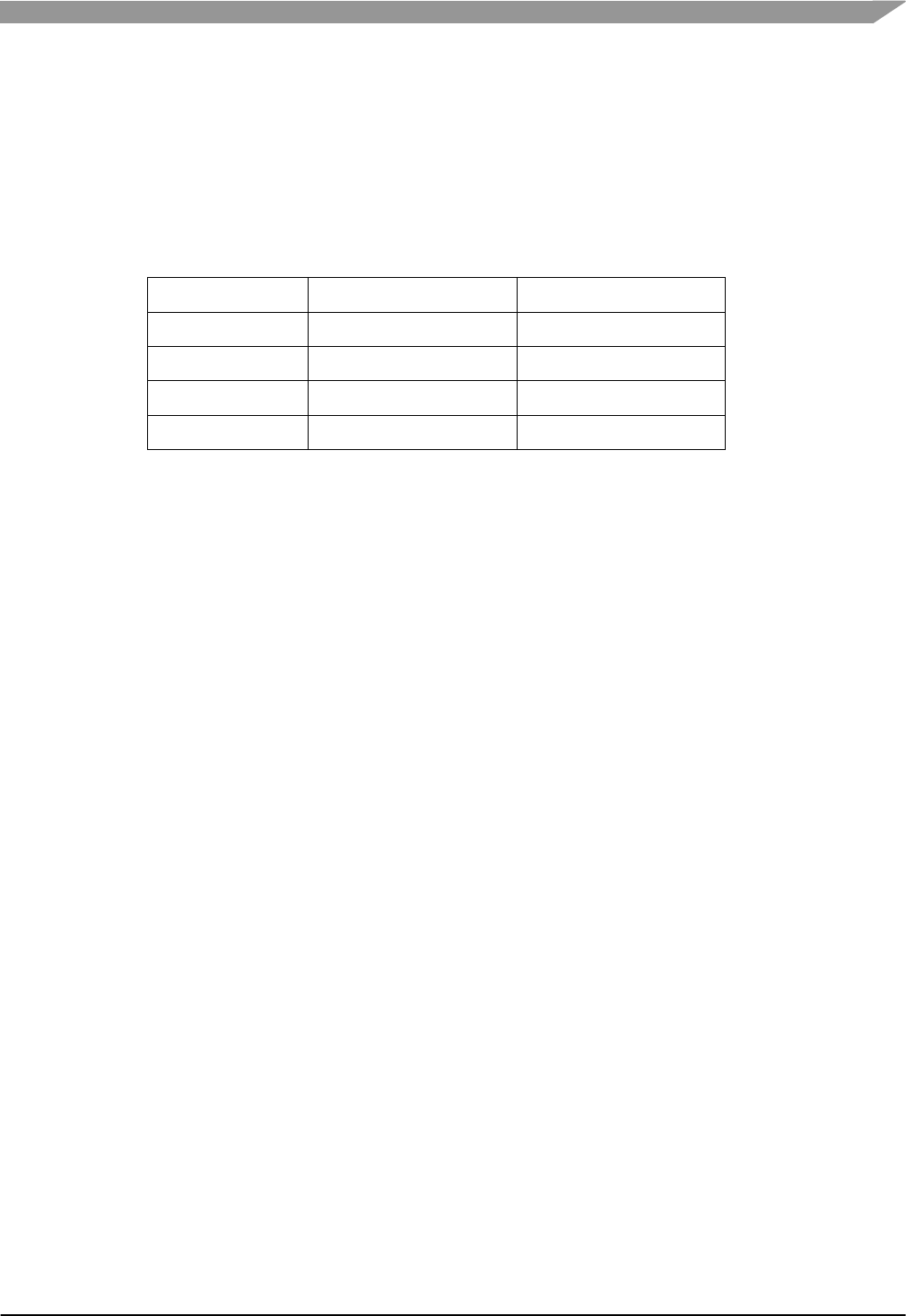
adds FlexMemory. See Table 1 for the difference in sizes of the memory map.
Table 1: Memory Map Size Differences between Derivatives
Part Number
MK60DN512VMD10
MK40DX256VMD10
Program Flash
512KB
256KB
System SRAM
128KB
64KB
FlexNVM
0KB
256KB
FlexRAM
4KB
4KB
10.1 CodeWarrior GCC Linker File
The linker file is located with the BSP files in \mqx\source\bsp\CustomBSP\gcc_cw\intflash.ld.
Modify the memory map. In this example, the following lines are changed to this code:
MEMORY
{
vectorrom (RX): ORIGIN = 0x00000000, LENGTH = 0x00000400
cfmprotrom (R): ORIGIN = 0x00000400, LENGTH = 0x00000020
rom (RX): ORIGIN = 0x00000420, LENGTH = 0x0003FBE0 /* Code + Const data */
ram (RW): ORIGIN = 0x1FFF8000, LENGTH = 0x00010000 /* SRAM - RW data */
/* kernel space starts after RAM variables (Location of MQX Kernel data + MQX heap) */
end_of_kd (RW): ORIGIN = 0x20007FF0, LENGTH = 0x00000000
/* Boot stack reused by MQX Kernel data */
bstack (RW): ORIGIN = 0x20007A00, LENGTH = 0x00000200 /* Boot stack */
end_bstack (RW): ORIGIN = 0x20007C00, LENGTH = 0x00000000 /* Boot stack end address
requires 4B alignment */
}
SECTIONS
{
__INTERNAL_SRAM_BASE = 0x1FFF8000;
__INTERNAL_SRAM_SIZE = 0x00010000;
__INTERNAL_FLASH_BASE = 0x00000000;
__INTERNAL_FLASH_SIZE = 0x00040000;
__INTERNAL_FLEXNVM_BASE = 0x10000000;
__INTERNAL_FLEXNVM_SIZE = 0x00040000;
__INTERNAL_FLEXRAM_BASE = 0x14000000;
__INTERNAL_FLEXRAM_SIZE = 0x00001000;
10.2 CodeWarrior Freescale Linker File
This toolchain option has two linker files, one for internal flash and the other for internal RAM. They
are located with the BSP files in:
Internal Flash: \mqx\source\bsp\CustomBSP\cw\intflash.lcf
Internal RAM: \mqx\source\bsp\CustomBSP\cw\intram.lcf

Freescale MQX™ RTOS BSP Porting Guide, Rev. 1, 11/2014
Freescale Semiconductor
38
1. Modify the internal flash linker file memory map. In this example, these lines are changed to
this code:
MEMORY
{
vectorrom (RX): ORIGIN = 0x00000000, LENGTH = 0x00000400
cfmprotrom (RX): ORIGIN = 0x00000400, LENGTH = 0x00000020
rom (RX): ORIGIN = 0x00000420, LENGTH = 0x0003FBE0 # Code + Const data
ram (RW): ORIGIN = 0x1FFF8000, LENGTH = 0x00010000 # SRAM - RW data
# kernel space starts after RAM variables (Location of MQX Kernel data + MQX heap)
end_of_kd (RW): ORIGIN = 0x20007FF0, LENGTH = 0x00000000
# Boot stack reused by MQX Kernel data
bstack (RW): ORIGIN = 0x20007A00, LENGTH = 0x00000200 # Boot stack
end_bstack (RW): ORIGIN = 0x20007C00, LENGTH = 0x00000000
}
KEEP_SECTION { .vectors_rom, .vectors_ram, .cfmconfig }
SECTIONS
{
__INTERNAL_SRAM_BASE = 0x1FFF8000;
__INTERNAL_SRAM_SIZE = 0x00010000;
__INTERNAL_FLASH_BASE = 0x00000000;
__INTERNAL_FLASH_SIZE = 0x00040000;
__INTERNAL_FLEXNVM_BASE = 0x10000000;
__INTERNAL_FLEXNVM_SIZE = 0x00040000;
__INTERNAL_FLEXRAM_BASE = 0x14000000;
__INTERNAL_FLEXRAM_SIZE = 0x00001000;
2. Modify the internal RAM linker file memory map. In this example, these lines are changed to
this code:
MEMORY
{
vectorram (RW): ORIGIN = 0x1FFF8000, LENGTH = 0x00000420 # SRAM - Vector table
rom (RX): ORIGIN = 0x1FFF8420, LENGTH = 0x00007BE0 # SRAM - Code + Const data
ram (RW): ORIGIN = 0x20000000, LENGTH = 0x00008000 # SRAM - RW data
# kernel space starts after RAM variables (Location of MQX Kernel data + MQX heap)
end_of_kd (RW): ORIGIN = 0x20007FF0, LENGTH = 0x00000000
# Boot stack reused by MQX Kernel data
bstack (RW): ORIGIN = 0x20007A00, LENGTH = 0x00000200 # Boot stack
end_bstack (RW): ORIGIN = 0x20007C00, LENGTH = 0x00000000
}
KEEP_SECTION { .vectors_rom }
SECTIONS
{
__INTERNAL_SRAM_BASE = 0x20000000;
__INTERNAL_SRAM_SIZE = 0x00008000;
__INTERNAL_FLASH_BASE = 0x00000000;
__INTERNAL_FLASH_SIZE = 0x00040000;
__INTERNAL_FLEXNVM_BASE = 0x10000000;
__INTERNAL_FLEXNVM_SIZE = 0x00040000;
__INTERNAL_FLEXRAM_BASE = 0x14000000;
__INTERNAL_FLEXRAM_SIZE = 0x00001000;
10.3 IAR EW-ARM Linker File
This toolchain option has two linker files, one for internal flash and the other for internal RAM. They
are located with the BSP files in:
Internal Flash: \mqx\source\bsp\CustomBSP\iar\intflash.icf

Freescale MQX™ RTOS BSP Porting Guide, Rev. 1, 11/2014
Freescale Semiconductor
39
Internal RAM: \mqx\source\bsp\CustomBSP\iar\ram.icf
1. Modify the internal flash linker file memory map. In this example, these lines are changed to
this code:
define symbol __ICFEDIT_region_ROM_end__ = 0x0003FFFF;
define symbol __ICFEDIT_region_RAM_start__ = 0x1FFF8000;
define symbol __ICFEDIT_region_RAM_end__ = 0x20007FF0;
define exported symbol __INTERNAL_FLASH_SIZE = 0x00040000;
define exported symbol __INTERNAL_FLEXNVM_BASE = 0x10000000;
define exported symbol __INTERNAL_FLEXNVM_SIZE = 0x00040000;
define exported symbol __INTERNAL_FLEXRAM_BASE = 0x14000000;
define exported symbol __INTERNAL_FLEXRAM_SIZE = 0x00001000;
2. Modify the internal RAM linker file memory map. In this example, these lines are changed to
this code:
define symbol __ICFEDIT_intvec_start__ = 0x1fff8000;
define symbol __ICFEDIT_region_ROM_start__ = 0x1fff8000;
define exported symbol __INTERNAL_FLASH_SIZE = 0x00040000;
define exported symbol __INTERNAL_FLEXNVM_BASE = 0x10000000;
define exported symbol __INTERNAL_FLEXNVM_SIZE = 0x00040000;
define exported symbol __INTERNAL_FLEXRAM_BASE = 0x14000000;
define exported symbol __INTERNAL_FLEXRAM_SIZE = 0x00001000;
define exported symbol __VECTOR_TABLE_ROM_START = 0x1fff8000;
10.4 Keil uVision Linker File
The linker file is located with the BSP files in \mqx\source\bsp\CustomBSP\uv4\intflash.scf
Modify the memory map. In this example, the following lines are changed to this code:
#define FLASHX_SECT_SIZE 0x800
#define USERFLASH_BASE_ADDR 0x00030000
; make sure this alignment matches the alignment in kernel_data.s in the bsp
FLASHX_START MY_ALIGN(ImageLimit(CODE), FLASHX_SECT_SIZE)
{
* (FLASHX)
}
RAM_VECTORS 0x1FFF8000 ; For ram vector table. Used when MQX_ROM_VECTORS is set to zero.
{
vectors.o (.vectors_ram)
}
KERNEL_DATA_END 0x20007FF0 ; RAM_END
{
* (KERNEL_DATA_END) ; end of kernel data
}
BOOT_STACK_ADDR 0x20007EF0
{
* (BOOT_STACK)
}
11 Post-Link Batch Files
If using PEx, previous changes to the BSP batch fiIe were done in Update IAR BSP Batch File or
Update Keil BSP Batch File.

Freescale MQX™ RTOS BSP Porting Guide, Rev. 1, 11/2014
Freescale Semiconductor
40
In this example, the ENET driver is removed and the Segment LCD driver is added. The BSP batch
file is located at \mqx\build\bat\bsp_CustomBSP.bat
1. Remove commands for removed drivers. In this example, delete these lines:
copy %MQXROOTDIR%\mqx\source\io\enet\enet.h %OUTPUTDIR%\enet.h /Y
copy %MQXROOTDIR%\mqx\source\io\enet\enet_rev.h %OUTPUTDIR%\enet_rev.h /Y
copy %MQXROOTDIR%\mqx\source\io\enet\enet_wifi.h %OUTPUTDIR%\enet_wifi.h /Y
copy %MQXROOTDIR%\mqx\source\io\enet\ethernet.h %OUTPUTDIR%\ethernet.h /Y
copy %MQXROOTDIR%\mqx\source\io\enet\macnet\macnet_1588.h %OUTPUTDIR%\macnet_1588.h /Y
copy %MQXROOTDIR%\mqx\source\io\enet\macnet\macnet_mk60.h %OUTPUTDIR%\macnet_mk60.h /Y
copy %MQXROOTDIR%\mqx\source\io\enet\macnet\macnet_rev.h %OUTPUTDIR%\macnet_rev.h /Y
copy %MQXROOTDIR%\mqx\source\io\enet\phy\phy_ksz8041.h %OUTPUTDIR%\phy_ksz8041.h /Y
2. Add commands for added drivers. In this example, add the lines:
copy %MQXROOTDIR%\mqx\source\io\lcd\lcd_twrk40d100m.h %OUTPUTDIR%\lcd_twrk40d100m.h /Y
3. Changed commands for header file name changes. If the BSP uses different header files for
derivative-specific driver details, the batch file needs to be updated to copy these files to the
\lib folder. In this example, the lines are changed:
copy %MQXROOTDIR%\mqx\source\io\flashx\freescale\flash_mk40.h %OUTPUTDIR%\flash_mk40.h /Y
4. Update the PSP batch file if the derivative header file is changed (done previously in Specify
MCU derivative in MQX). The batch file runs after the PSP project is built, and copies
header files to the \lib folder to be used when compiling the application. The batch file must
be updated to copy the different header file. In this example, modify the batch file found at
\mqx\build\bat\psp_CustomBSP.bat:
copy %MQXROOTDIR%\mqx\source\psp\cortex_m\cpu\MK40D10.h %OUTPUTDIR%\MK40D10.h /Y
12 CodeWarrior Debugger Memory File
In this example, the file is \mqx\source\bsp\CustomBSP\<toolchain>\dbg\CustomBSP.mem.
This is a text file, and is simple to modify manually. Another option is to use the .MEM file provided
by CodeWarrior. Use the files located in <CodeWarrior Installation
Path>\MCU\ARM_EABI_Support\Memory_Config_Files. For this example, these steps update
the .MEM file:
1. Copy the .MEM file provided in CodeWarrior. In this example, copy the file <CodeWarrior
Installation Path>\MCU\ARM_EABI_Support\Memory_Config_Files\K40DX256M10.mem.
2. Paste the file into the BSP and rename to the same .MEM file that was cloned, overwriting
the cloned file. In this example, the resulting file is
\mqx\source\bsp\CustomBSP\<toolchain>\dbg\CustomBSP.mem.
13 Porting Example Applications
Here are the steps used when testing this ported BSP example with the example applications listed
in the next section:
1. Change the toolchain setting for the MCU derivative in the application example project. In
CodeWarrior, the Target Type is changed in the Connection for the Debug Configuration. In
this example, the MCU derivative is changed to support the part number
MK40DX256VMD10.

Freescale MQX™ RTOS BSP Porting Guide, Rev. 1, 11/2014
Freescale Semiconductor
41
13.1 Testing CustomBSP
The following examples were tested in this porting example, to ensure the BSP port to the TWR-
K40D100M was successful:
flashx - tests changes to memory map using the flashx driver. The example is
located at \mqx\examples\flashx\<toolchain>\flashx_CustomBSP.
lcd – tests Segment LCD driver added to BSP. Uses module TWRPI-SLCD that
comes with TWR-K40D100M board. The example is located at
\mqx\examples\lcd\<toolchain>\lcd_CustomBSP.
pe_demo – tests PEx integration in BSP. Refer to the tutorial in the document at
\doc\tools\cw\FSL_MQX_in_CW_10_x.pdf for details on using this demo. The demo
is located at \demo\pe_demo\<toolchain>\pe_demo_CustomBSP.
lowpower – tests using LPM driver for low-power mode and clock configuration
changes. The example is located at
\mqx\examples\lowpower\<toolchain>\lowpower_CustomBSP
flexnvm – tests memory map changes, and addition of FlexMemory to BSP. The
flexnvm example uses the EEPROM feature of FlexMemory to store non-volatile
data. The example is located at
\mqx\examples\flexnvm\<toolchain>\flexnvm_CustomBSP.
i2s_demo – tests different pins in SAI interface. Uses the Tower System module
TWR-AUDIO-SGTL for the audio codec. NOTE: Need jumper on TWR-K40D100M
pins 5-6 on J4 for this example to play audio output. The example is located at
\mqx\examples\i2s_demo\<toolchain>\i2s_demo_CustomBSP.
mfs_usb – tests USB driver, including USB clock divider change. Tested with and
without PEx in the BSP. This example mounts a USB flash drive, and is located at
\mfs\examples\mfs_usb\<toolchain>\mfs_usb_CustomBSP.
14 Conclusion
Freescale MQX RTOS is a scalable RTOS that complements Freescale’s broad family of micro-
controllers, including Kinetis. The provided MQX BSPs can be ported across all the supported
Freescale devices using the steps outlined in the document Freescale MQX™ RTOS BSP Porting
Guide (document MQXBSPPG), and using this document for a detailed example. For the most up-
to-date MQX information and documentation, or to download MQX RTOS, visit the
freescale.com/mqx.
