Phase One 645 Af Users Manual Capture 4 Guide
Phase-One-645-Af-User-Guide-778392 phase-one-645-af-user-guide-778392
645 AF to the manual 36aa9dd4-792e-4fba-aa5c-2ac1051f0293
645 AF - User Guide 645AF_UG_EN Free User Guide for Phase One Camera, Manual
2015-02-06
: Phase-One Phase-One-645-Af-Users-Manual-518342 phase-one-645-af-users-manual-518342 phase-one pdf
Open the PDF directly: View PDF ![]() .
.
Page Count: 106 [warning: Documents this large are best viewed by clicking the View PDF Link!]
User Guide Phase One Camera

2
On rights
©2008 Phase One A/S. All rights reserved. Made in Denmark.
Ver. 1.11 - Updated 18 August 2008
Learn more about Capture One 4 on www.phaseone.com/4
Learn more about Phase One 645 AF on www.phaseone.com/camera
Cover and back images Photo by: Torben Eskerod
On liability
The information in this user guide is provided “as is”.
Under no circumstances, including negligence, shall Phase One be liable for any incidental, special, direct, indirect or
consequential damages arising out of or relating to use of the information provided in this guide with or without the software
described in the guide.
Trademarks & acknowledgements
Capture One and Phase One are either registered trademarks or trademarks of Phase One A/S in the European Union
and/or other countries.
All other trademarks are the property of their respective owners.

3
Contents
1.0 Introduction 4
1.1 Open Platform – Freedom of Choice 4
1.2 warranty 5
1.3 Recommended hardware 5
1.4 Installing and Activation of software 6
1.5 Deactivation of Capture One 4 8
1.6 Screen calibration 9
2.0 The Body - the system 10
2.1 Unpacking the system 10
2.2 Batteries for camera 12
2.3 Batteries for the back 13
2.4 The parts of the camera system 14
2.5 Attach and remove lens 15
2.6 Attaching the back 16
2.7 The display 17
2.8 The buttons 18
2.9 LED lights 18
2.10 Setting diopter 19
2.11 Adjusting the Strap 19
2.12 Eyepiece shutter 20
2.13 Setting date and time 20
3.0 Basic functions 22
3.1 Setting ISO 22
3.2 Easy Photography 23
3.3 Measuring light – Exposure Metering 25
3.4 Focus modes 27
3.5 Using focus lock and infrared focusing 32
3.6 Shutter release modes 34
3.8 Flash photography 39
3.9 ashcompensationsettings 42
4.0 Advanced functions 43
4.1 Exposure Compensation 43
4.2 AE Lock 44
4.3 Auto Bracketing 46
4.4 Taking photos with the mirror up 48
4.5 Long exposure - Bulb Mode 49
4.6 Camera display light 49
4.7 Front/rear dial lock mechanisms 50
4.8 Depthofeld 51
4.9 Infrared photography 52
5.0 Tethered shooting 54
5.1 Connecting 54
5.2 Driver set-up 54
5.3 Tethered operations 55
6.0 The Back 56
6.1 CF card usage 57
6.2 Mounting and dismounting card on computers 60
6.3 Navigating the Back menu 62
6.4 Playmode 65
6.5 Playmode – zoom functions 66
6.6 Menu Mode 68
7.0 Custom function 80
7.1 Setting custom functions 80
7.2 Types of custom functions 81
Custom Functions overview 85
8.0 Lenses and Multi Mount 86
8.1 Functions of the Phase One lens 86
8.2 Function of the Phase One lens adaptor 87
8.3 List of alternative lenses 88
8.4 Lens Cast 89
8.5 4simplestepstocalibrateonxedlenses(MAC) 90
8.6 Largeformatandstitchedimages(MAC) 90
8.7 4simplestepstocalibrateonxedlenses(PC) 91
8.8 Largeformatandstitchedimages(PC) 92
9.0 Software 94
9.1 Getting started 94
9.2 Importing from CF card 95
10.0 Large format and technical cameras 96
10.1 Large format photography 96
10.2 Technical cameras 97
11.0 Maintenance 98
11.1 changing the focusing screen 98
11.2 Battery socket 99
11.3 Tripod/Electronic shutter release contact 99
11.4 Cameradisplayerror-notication 100
11.5 Lens maintenance 101
11.6 Back Maintenance 101
11.7 housingspecication 102
11.8 P+seriesTechnicalspecications 103
11.9 End User support Policy 104

4
1.0 Introduction
1.1 Open Platform – Freedom of Choice
Thank you for choosing the Phase One 645 Camera.
The Phase One 645 Camera provides you the most powerful digital
camera solution whether you are working portable in the eld, or
tethered in a studio.
When shooting portrait, landscape, fashion, wedding, product or
architectural photography you will always nd a solution from Phase
One that ts your needs.
The camera system gives you the absolute best solution when it comes
to image quality and workow thanks to the ongoing research and
development made by the Phase One through more than 20 years.
Phase One is committed to not only provide the best digital solution
for the professional photographer, but also to ensure the photographer
freedom of choice regarding lenses, bodies, back, software, and
accessories.
The Capture One raw workow software for Mac OS X and Windows™ is
the new generation 4 software, with tethered shooting as your option.
The P+ Series of backs are legendary in the photographic business,
used by world class photographers for years. The system comes in a
suitcase and is ready to be used right out of the box.
We sincerely hope you will enjoy working with this new and innovative
camera platform.

5
1.2 warranty
Please read the enclosed warranty certicate. Should any problem
occur, please contact the place of purchase, your local dealer for
consultancy. – Do not try to repair the camera yourself, unauthorized
attempt for repairing will termite the warranty.
1.3 Recommended hardware
Capture One 4 may run on older computers, but Phase One recommends
following the minimum requirement to ensure the best result from
Capture One 4.
Apple® Macintosh®:
G4, G5 or Intelbased Macs
768MB RAM
1GB of free hard disk space
Calibrated color monitor with 1280x800, 24-bit resolution
Mac OS X 10.4.11 or Mac OS X 10.5
Microsoft® Windows®:
Intel® Pentium® 4 or equivalent
768MB RAM
1GB free hard disk space
Calibrated color monitor in 1280x800, 24-bit resolution
Windows XP®, Service Pack 2 or higher
Windows Vista®
Microsoft® .NET Framework 3.0 Redistributable package – In case you
do not already have this installed, Capture One will initiate installation
of this.
We would recommend upgrading your computer in the areas below
if you work with high pixel-count cameras or simply want to optimize
performance:
Use processors with multiple cores, e.g. Intel Core™ DUO or better.
Having 2GB RAM or more.
Plenty of hard disk space for your images.
6
1.4 Installing and Activation of software
You can only install Capture One 4 when your computer is connected
to the internet. unless you choose to install DB only.
Install on Mac OS X:
Capture One software includes an easy-to-use installer that will install
all the software necessary to run the application on Mac OS X.
To install the software follow the procedure below:
1. Either load the Capture One DVD, or download the application from
the Phase One website: www.phaseone.com.
2. Open the Capture One disk image
3. Read and accept the license agreement presented
4. Drag the Capture One icon to the Applications folder
5. Open Capture One from your Applications folder
Install on Windows:
Capture One 4.1 includes an easy-to-use installer that will install all
the software you need to run the application on a Windows based
computer.
To install the software follow the procedure below:
1. Either load the Capture One DVD, or download the application from
the Phase One website: www.phaseone.com.
2. Run the executable software install le.
3. Read and accept the license agreement presented
4. Follow the on-screen instructions to complete the installation.
- In case you do not already have Microsoft® .NET Framework 3.0
installed, Capture One will initiate installation of this.

7
To activate Capture One 4 you normally need to be connected to the
internet. But installing as Digital Back Only does not need internet
connection.
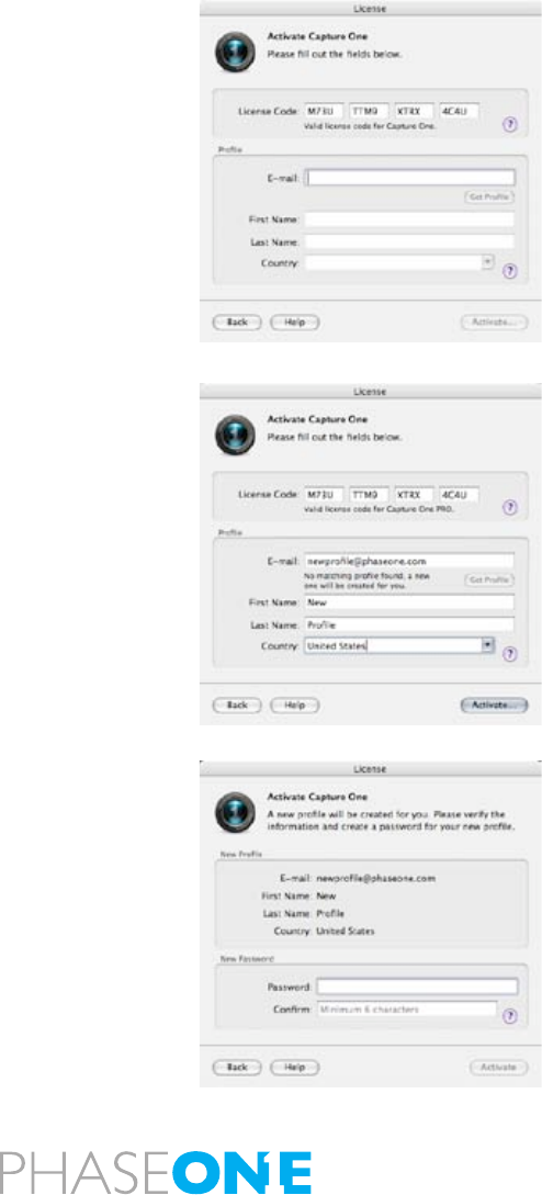
Open the license activation dialogue via the menu Capture
One>License.
Your rst step is towards activating Capture One is by opening the
license activation dialogue in the application as illustrated.
Enter your License code and personal details In the license activation
dialogue, type in the license code provided with your purchase of
Capture One. You received the License code either by email or with the
original software package.
Type in the personal details that you want to register along with your
software activation. Once you have entered the information press the
“Activate License” button and your activation will be validated by Phase
One’s activation server. Your software is now activated and ready
for use!
Troubleshooting
If you are experiencing problems activating the software, follow the
instructions provided in the application, read the software manual
enclosed or visit our website for inspiration and troubleshooting: http://
www.phaseone.com/support

8
1.5 Deactivation of Capture One 4
To deactivate Capture One 4 from a computer you need to be connected
to the internet.
Open the license dialogue via the menu Capture One>License.
Press the Deactivate button.
Once you deactivate Capture One, the application will return to trial
mode. If the trial period for the computer has expired, all current and
pending processing will be cancelled, and you will not be able to
continue working with the application until you reactivate it.
Conrm that you want to perform the deactivation. After doing so, you
can activate Capture One on another computer.

9
1.6 Screen calibration
Your monitor is key-element in your daily workow. One thing that
assists your ability of viewing the captures you have made is by using
color neutral light.
Consider your monitor the new digital lightbox. To ensure accuracy,
monitors need to be hardware calibrated for accuracy. A quality monitor
and calibration tool provides you with a guarantee that what you are
seeing on screen is correct. Once a monitor has been calibrated, the
color and brightness controls should be locked to prevent inadvertent
changes.
Hardware-based monitor calibrators are now available at reasonable
prices. The process is simple, quick and enables images to be judged
with certainty. Higher level monitors have internal calibrating software
that works with professional calibration devices for ultimate accuracy.

10
2.0 The Body - the system
The Phase One Camera system is created to provide as much exibility
and openness as possible. Phase One have for years been producing
the 2 lines, Classic and Value Added, below here you can see the
content of the 2 different kits.
2.1 Unpacking the system
The Phase One 645AF system is delivered in a case created for the
travelling photographer, the waterproof and impact resistant case has
the standard measurements of carry-on baggage in airplanes.
Open the case by pressing and pull-back the latches on the front/
opening.
Classic:
The case is exible inside, created for you to decide the actual content
and interior of the case. But as delivered the case will hold:
• Phase One 645 AF body with
• P+ Digital Back
• Phase One 80mm f 2.8 Lens
• Waterproof exible case in carry-on size
Pouch 1
• 4.5 meter FireWire cable
• Digital back duo-battery charger
• Digital back battery
• Capture One raw workow software
• Battery charger power supply
• International outlet adaptors
• Protection caps body, lens and back
Startbox
• USB key with User Guide, technical documents and more
• Quick Guide
• Warranty Brochure

11
Value Added:
Case
• Phase One 645 AF body with
• P+ Digital Back
• Phase One 80mm f 2.8 Lens with lens hood and cap
• Waterproof exible case in carry-on size with room for laptop
computer
• CF card installed
• 4.5 meter FireWire cable
• QP reference grey card
• Lens cast calibration card
• Capture One raw workow software
• Sensor Cleaning Kit
Startbox
• USB key with User Guide, technical documents and more
• Quick Guide
• Warranty Brochure
Pouch 1
• Digital back battery charger
• Two digital back batteries
Pouch 2
• Battery charger power supply
• International outlet adaptors
• CF card reader
• CF card reader cable
• Camera power module
Accessories Box
• Phase One 645 AF-HB multi-mount
• Protection caps body, lens and back
• Lens cleaning cloth
12
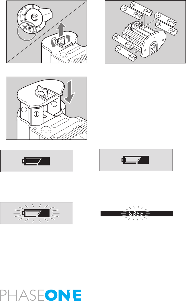
2.2 Batteries for camera
Set the shutter release mode selector lever to “L” (to turn the power
off).
Use six “AA” alkaline.
NiCD batteries should only be used in the camerabody if CF07 is set
on rechargeable.
1. Lift the battery case lock lever, turn it counter clockwise and pull out
the battery holder.
2. Insert fresh batteries with the + and - ends as shown in the drawing.
3. Return the battery holder to its case and lock it by turning the lever
clockwise. Make sure it is rmly attached.
- Be sure the batteries are placed with proper polarity
Checking the Battery Power
Set the shutter release mode selector lever to “S” (to turn the power
on).
Check the battery condition in the lower right corner of the top LCD
display.
When replacing the batteries, be sure to use six new batteries of the
same type. Do not mix different types of batteries or old batteries with
new ones. NEVER throw out batteries.
C
S
L
M.UP
The batteries are sufficiently charged. There is little power remaining. Have
new batteries on hand. Camera will still
operate.
There is very little power remaining.
Camera will not operate. Set the shutter
release mode selector lever to “L” (to
turn the power off) and replace the
batteries with new ones.
When the batteries are emptied for
power, “batt” flashes on the main
LCD and the viewfinder’s LCD when
the shutter release button is pressed.
13
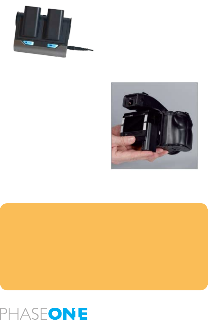
2.3 Batteries for the back
When the system is unpacked the rst thing to do, is to give the batteries
a full charge.
In the Value Added Suitcase comes with two 7.2 volt Lithium-Ion batteries.
Only one battery is used in the P+ back at a time, but it is recommended
to charge both batteries fully before you start.
While charging the batteries, you can still use the camera back if you
connect it to the IEEE1394/FireWire port on your computer, by using
the 6pin FireWire.
The charger can adapt to voltages within a range of 110 to 250 volts.
It comes with an international set of source outlet adaptors (placed in
the suitcase utility compartment), please select one that ts your outlet,
and mount it by sliding it in from the top.
Connect the unit to the outlet and charge the batteries (approximately
2,5 to 3 hours).
NEVER throw out batteries, when a battery does not work, deliver the
battery for appropriate disposal.
Purchasing extra batteries
The Phase One P+ back comes with two 2500mAh batteries. If you
need to purchase extra batteries Phase One recommend Canon BP
915 2500 mAh.
Due to difference in the tolerances of some third party batteries, these
may not t into the digital back’s battery compartment. Do not try to
force a battery into the compartment. When pressing the battery release
button it should slide in without problems.
Warning!
•Only use the Charger to charge the specified batteries
•Do not allow charger to get wet or get exposed to moisture
•Keep the Charger out of reach of children
•Once charging is completed, unplug the transformer from power source
•Only use the original mains adaptor 12V DC or car lead
•Never apply excessive force when connecting or disconnecting a battery or contact
plate.
•Keep all contacts clean.
•Do not force down any of the contacts.
•Do not short-circuit the contacts.
•Never store the battery connected to the charger for an extensive period of time.
•Do not expose to excessive heat or naked flame.
•Do not dismantle or carry out any alteration to the product

14
2.4 The parts of the camera system
Self timer button
Main LCD backlight button
Multiple exposure button
Focus point selector button
Set button
Flash auto adjustment selectbutton
Auto bracketing button
Multiple exposure mode button
Auto exposure lock button
Digital back LCD panel
Play button
Menu button
White Balance button
ISO button
Digital back ON/OFF button
Digital back external connection
645 AF
Diopter adjustment dial
Digital back relase lock
Digital back relase button
Cover for CF card slot
Syncro terminal
Electronic shutter release contact
Lens release button
Focus mode selector lever
Strap lug
Hot shoe
Exposure mode dial lock/release button
Exposure mode dial
AF assist infrared light
Mirror
Electronic contacts
Lens mount alignment mark
Depth of eld preview button
AF lock button
Drive dial
Shutter release button
Front dial
Strap mount
Rear dial
Main (top) LCD
Eyepiece shutter lever
Diopter adjustment lens
LCD screen
Digital back power on/off
Digital back power on/off
External power socket
Battery case lock lever
Battery case
Tripod socket
Multiconctor external back control
Flash sync ONLY for use on technical
cameras or pther platforms
Flash sync Remote camera control
15
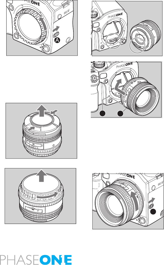
2.5 Attach and remove lens
1. Remove the front body cap, just like you would remove a lens, by
pushing the lens release button backward and then turn the front body
cap or the lens itself counter clockwise and lift out.
2. Align the white alignment dot of the lens [A](on the shiny ange) with
the camera’s white dot[B], t the lens into the camera and rotate it
clockwise until it clicks into place.
To remove the front lens cap, squeeze the shiny sections together
and lift out.
To remove rear lens cap turn it counterclockwise.
Removing
While sliding the lens release button back, rotate the lens counter
clockwise until it stops and lift it off.
After removing the lens from the camera body, protect both ends by
attaching the caps.
Oil, dust, ngerprints or water on the electronic contacts could result
in malfunction or corrosion. Wipe such impurities off with a clean piece
of cloth.
Do not touch the distance ring or other rotating parts when attaching
the lens. - When installing a lens, do not press the lens release button.
MF
80mm
1:28
AF
22
22
11
11
44
ft
m
A
B
A

16
2.6 Attaching the back
The P+ back is fully integrated with the camera body and is a part of the
whole camera system.
When no cassette is attached to the Phase One 645AF camera house
the mirror is up and the shutter is open. This is the correct position
when no back is attached.
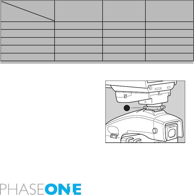
When attaching the P+ back to the camera body the shutter will close
and the mirror comes down. It is important to ensure that the bottom
part of the P+ back is pressed well into the locking mechanism on
the camera back before the upper locking mechanism is pressed
together.
Failure to do this can cause an error with the camera body. The error is
a state of continuously opening and closing the shutter. If this occurs,
remove the P+ back.
Please be aware that the shutter should be in the correct starting
position (shutter open), if this is not the case, attach and remove the
P+ back again to make sure that the camera body gets in the correct
starting position.
17
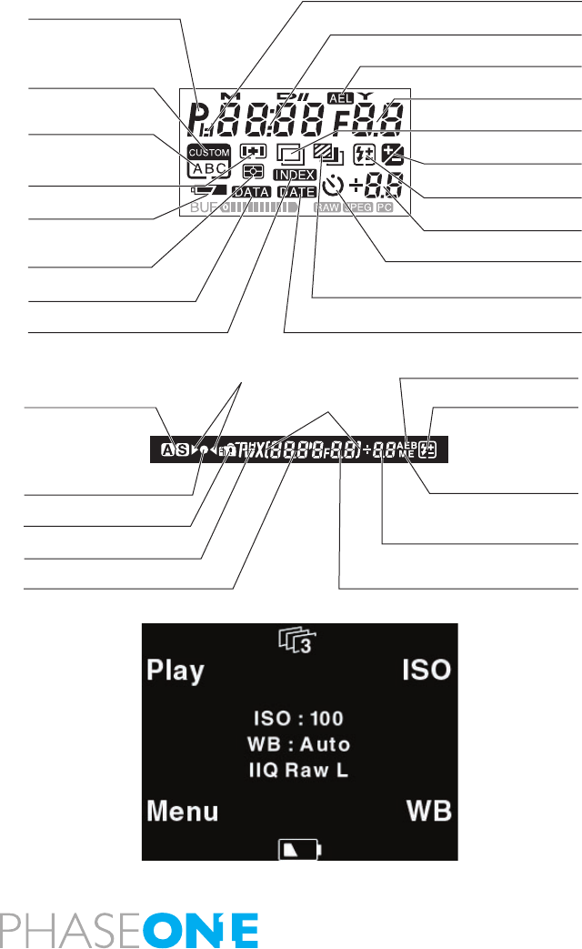
2.7 The display
The display on the camera housing will provide valuable information
on shutterspeed/aperture value also you nd information on exposure
program, compensations see the drawing for explanation; the most
relevant information regarding the capture can be read on the bottom
display in the viewer along with the auto-focus mark indicating that the
focus is in place.
The display on the back is a multifunctional display, the menus changes
depending on the status and choices you make.
Besides providing navigation, the display on the back can work as
preview screen.
Exposure metering mode
mark
Superimposing mode (data)
Superimposing mode (index)
Auto bracketing mode mark
Self timer mode mark
Superimposing mode (date)
Program mode mark
Program shift indicator
Shutter speed (second)/Month and date
AE lock mode mark
Aperture/Year
Multiple exposure mode mark
Exposure compensation
mode mark
Flash compensation mark
Custom function
mode mark
User function mode mark
Battery power indicator
AF area mark
Exposure compensation value
AE lock indicator
Defocus indicators
Auto bracketing mode mark
Flash auto adjustment
mode mark
Multiple exposure
mode mark
Aperture
Flash charge indicator
Exposure compensation value
/ Dierence between metered
and set exposure values
Exposure metering
mode display
Focus marks:
Displayed when
subject is in focus
Caution mark
Exposure mode mark
Shutter speed
18
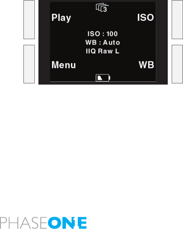
2.8 The buttons
The back is equipped with four buttons, these buttons will take you
through all functions of the back, and the buttons will change function
to match the menu shown on the display. Read more on the menus in
the chapter regarding this.
2.9 LED lights
When the camera is powered up you will see a short blink in the green
and red LED’s in the right hand side of the display and you will hear a
ready beep. The lights will turn off immediately. This is an indication
that the camera is ready to capture.
Green: When capturing an image the green LED is blinking rapidly to
indicates that the P+ back is busy.
Steady green light indicates that the backlight of the display is dimmed
but the camera is still ready to shoot.
(The time before this happens can be set in the P+ back and is described
later under “Menu mode”)
RED: If the red LED is on this indicates that the P+ back is writing to the
storage media thereof the buffer is not emptied.
The red LED indicator located just beside the CF-cardslot under the
cover in the left side is assigned to only indicate CF card activity.
When the red CF-slot LED is on do not remove the card from the card
slot! This can damage the formatting of the card, resulting images or
data might be lost or corrupted.
•
•
19
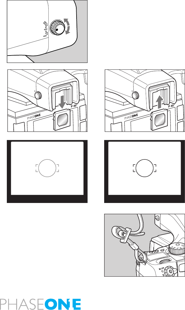
2.10 Setting diopter
Look through the viewnder and make sure that the focus frame
(Rectangle with Circle) is in sharp focus. If it is not, turn the diopter
adjustment dial in the “–” direction if you are nearsighted, in the “+”
direction if you are farsighted. If this is not sufcient you may require an
optional diopter correction lens. See below.
Point the camera at a bright, plain object such as a white wall when
making this adjustment.
Replacing the Diopter Correction Lens
If there is dirt or dust on the lens surface, remove it with a blower or
sweep it off gently with a lens brush.
If there are ngerprints or dirt on the lens surface, wipe them off with a
piece of clean, soft gauze.
Using solvents could discolor the diopter correction lens frame.
1. Remove the lens supplied with the nder by pulling it downward.
2. Push the replacement diopter correction lens upward into the
viewnder’s eyepiece frame until it clicks into place.
2.11 Adjusting the Strap
Put the neck strap through the mounts and secure it to the buckle
as illustrated.
After attaching the strap, pull it and make sure it does not loosen at
the buckle.
Diopter not matching Diopter matching
20
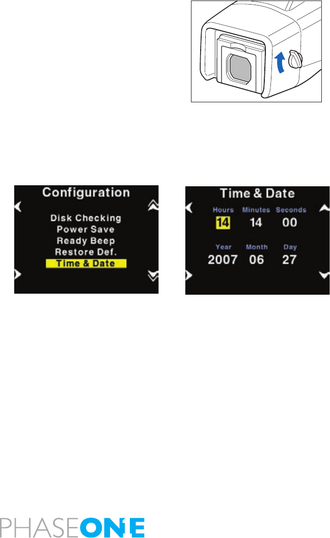
2.12 Eyepiece shutter
Close the eyepiece shutter when there is a strong light source behind
the camera or when pressing the shutter release button without looking
through the viewnder.
(This prevents exposure error due to light entering from the
viewnder.)
Turn the eyepiece shutter lever in the direction of the arrow.
2.13 Setting date and time
Date and time is set and controlled through the digital back.
Default date and time is GMT+1.
If the digital back has been without power for a longer period of time,
it will automatically ask you to setup time and date when it is powered
up.
In the “Time & Date” menu you can set the time and date using the four
buttons on the P+ back. Left side buttons will step through the hours,
minutes and seconds eld, while the right up and down buttons can be
used to set the value of the elds.
The time and date is applied to all les captured with the P+ back.

21

22
3.0 Basic functions
3.1 Setting ISO
ISO functionality is controlled by the back.
The default ISO setting is ISO 50 or 100 depending on the back of the
Camera system. A rule of thumb is that the higher ISO you are using,
the higher is the degree of noise in the image, though Capture One has
a powerful noise reduction.
Depending on the back the Phase One ISO scale is currently 50, 100,
200, 400, 800 OR 100, 200, 400, 800, 1600 using the button on the top
left, when in the main menu on the back scroll up and down and press
“enter” and the desired ISO is chosen, OR if using tethered mode use
the Capture panel in the Capture One application.
ISO and White Balance
When the display is in its home position the two buttons to the left,
ISO and WB brings you directly to the ISO and White balance settings,
where you can scroll up and down, and select the setting you want with
the “Enter” button. Also White Balance can be controlled by Capture
One if you are working tethered.
23
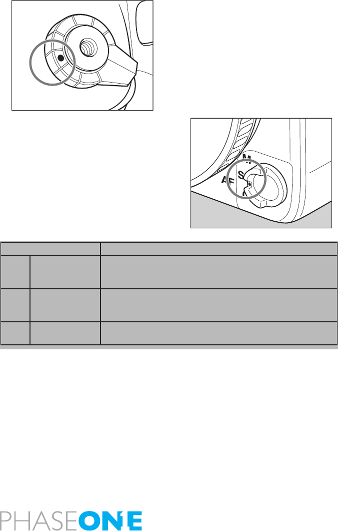
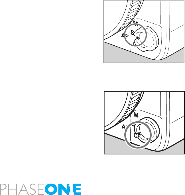
3.2 Easy Photography
1. Set the shutter release mode selector lever to “S” (single-frame
advance mode).
There are two shutter release modes: “S” (singleframe advance mode)
and “C” (continuous advance mode).
When set to “L,” the power is turned off.
2. Set the focus mode selector lever to “S” (single focus mode).
There are three focus modes: “S” (single focus mode), “C” (continuous
focus mode) and “M” (manual focus mode).
3. Set the exposure mode selector dial to “P” (program auto
exposure).
There are four exposure modes:
“P” (program AE),
“Av” (aperture priority AE)
“Tv” (shutter priority AE)
“M” (manual mode).
C
S
L
M.UP
Focus Mode Focusing
S Single focus
mode
Half-press the shutter release button to focus. When the
focus mark lights, the focus is fixed and the shutter can be
released.
C Continuous
focus mode
The camera keeps focusing continuously while the shutter
release button is half-pressed. The shutter can be released
regardless of whether or not the focus mark is lit.
M Manual focus
mode
Focus manually.
24
P: Program AE - The aperture and shutter speed are determined
automatically according to the shooting conditions. This mode is best
suited for general photography, since it allows you to concentrate on
the shooting. You can change the shutter speed and aperture by turning
the front and rear dials while the “P” (Program AE) mode is selected.
Av: Aperture priority AE - Set the desired aperture and the camera
selects the correct shutter speed. Use this mode to control depth of
eld.
Tv: Shutter priority AE - Set the desired shutter speed and the camera
selects the correct aperture. Use this mode to stop motion.
M: Manual mode - Set this mode when you want to use special
combinations of the aperture and shutter speed.
4. Exposure metering mode is automatically set to average/spot
exposure metering before exposure metering is performed.
There are three exposure metering modes: In the “A” mode the average
brightness in the entire frame is measured with emphasis on the center
of the frame. The brightness at a specic spot in the center of the frame
is metered in the “S” mode. The “A-S” mode automatically switches
between these two modes depending on the contrasts in the picture.
)
NOTE:
When a polarizing filter is used, ensure
that a circular polarizing filter(C-PL)
is used. The correct exposure cannot
be obtained with a normal(linear)
polarizing filter (PL).
P
Av
Tv
M
X
CF
EL
25
3.3 Measuring light – Exposure Metering
1. Exposure mode mark is displayed when the exposure mode button
A is pressed. Since three different exposure modes are displayed
sequentially when either the front or rear dial is turned, select an
appropriate exposure mode.
2. Press the SET button or exposure metering mode button A to enter
the setting.
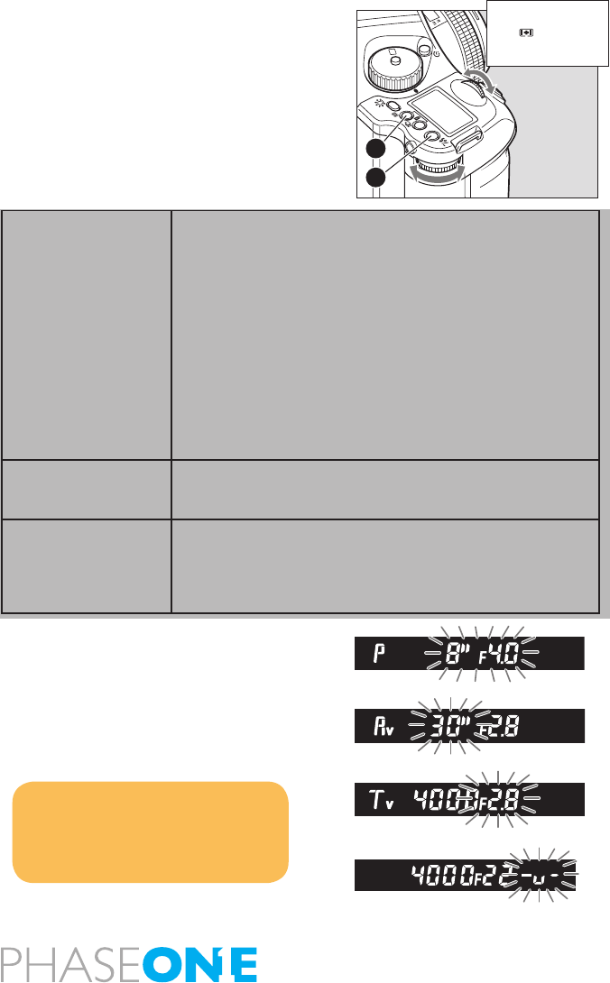
Exposure Warnings
With an inappropriate exposure setting, when shooting subjects that
are too light or dark, the user is warned by the ashing external LCD or
the LCD inside the viewnder.
At such times, the correct exposure cannot be obtained.
Warnings that the exposure is outside the metering range
• Program AE (P)
The shutter speed and f-number blink.
• Aperture priority AE (Av)
The shutter speed blinks.
• Shutter priority AE (Tv)
The f-number blinks.
• Manual mode (M)
The exposure metering value difference is displayed.
Average/spot auto
exposure metering
Exposure metering is performed after automatically
selecting average/spot exposure metering.• Depending
on the subject conditions, center-weighted average/spot
exposure metering is selected automatically, and the
correct exposure is measured.
• Spot exposure metering is automatically selected when
the brightness of the spot exposure metering range
becomes darker than the brightness of the entire screen.
• If there is very little difference between the spot exposure
metering value and center-weighted average exposure
metering value, the correct exposure level is obtained as
the intermediate value.
Center-weighted
average/spot
exposuremetering
The average brightness of the entire screen is measured,
emphasizing the center of the screen.
Center spot exposure
metering
The brightness of an area equivalent to 7.6% at screen
center is measured, and the exposure is determined. The
circle at screen center serves as a general guideline. This
mode is suited to measuring subjects with strong contrasts
or measuring only screen portions.
NOTE:
you can change the amount of
time the metered value is shown by
entering Custom Settings C-04.
SET
AEL
P
Av
Tv
M
X
CF
B
A
26
Exposure compensation
In some situations, such as a great difference between the subject
and background brightness or overall subject tones that will not meter
correctly because they are all black or white, the resulting photograph
may be under- or overexposed. When this occurs, use the exposure
compensation function. Exposure compensation can also be used
when you want to intentionally create overexposed or underexposed
pictures.
1. When exposure compensation button A is pressed, [+/-] appears on
the external LCD. When the front or rear dial is turned counterclockwise,
the exposure is increased; conversely, when it is turned clockwise, it is
decreased. The exposure compensation value can be checked on the
external LCD or LCD inside the viewnder.
2. After taking the pictures, press exposure compensation button A
again to return the exposure compensation value to 0.
The exposure compensation value mark on the external LCD is cleared,
and the exposure compensation function is released.
After taking pictures using the exposure compensation feature, be sure
to return the exposure compensation dial to the “0” position.
Exposure compensation is also possible during AE lock.
The shutter speed changes with exposure compensation in manual
mode (“M”).
Display of the exposure compensation of the viewnder LCD
- Without usage of Metz Flash.
NOTE:
1. The width of the exposure compensation step can be changed.
Custom settings 01
2. The maximum exposure compensation step can be changed to ±5EV.
Custom settings C-05 .
Exposure Mode Exposure Compensation display
P Program AE
The set value is displayed
Av Aperture priority AE
Tv Shutter Priority AE
M Manual mode The difference between the metered
value and the set exposure value is
displayed
X Synchro mode Not displayed
SET
AEL
P
Av
Tv
M
X
CF
27
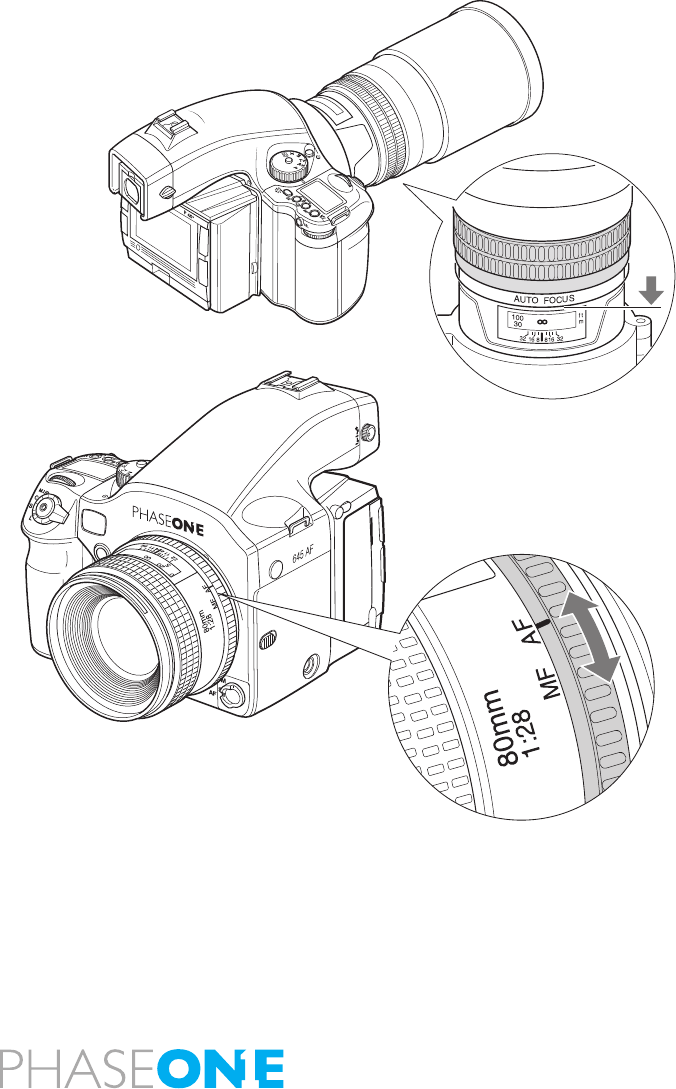
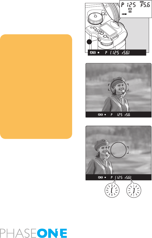
3.4 Focus modes
If autofocus AF is desired, chose AF on the focusing selector ring on the
lens, then chose between S(single) and C(continuously) focusing. The
Focus selection ring on the lens will help you to rapidly switch between
AF and M, without having to change your grip of the camera.
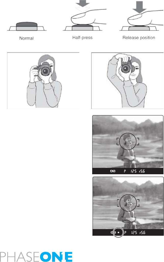
The shutter release button has a two-step action. When pressed lightly
it stops at a certain point. In this manual this position is called the “half-
press” position. When you “half-press” this button, the camera functions
are activated. When the shutter button is pressed further down, the
shutter is tripped. This position is called the “full-press” position.
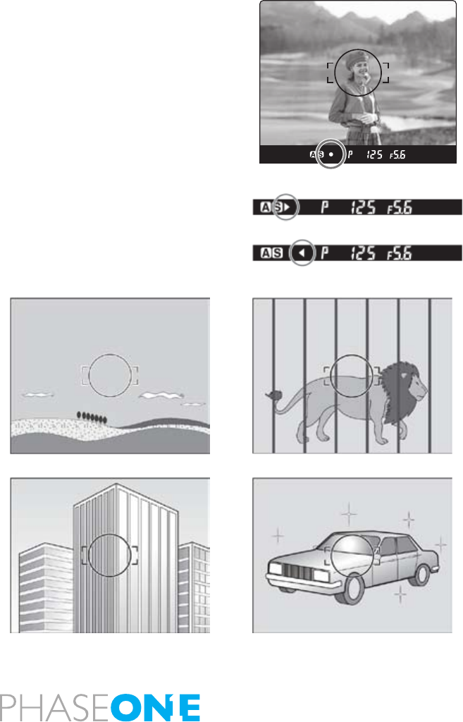
When you “half-press” this button, camera functions are activated.
1. Aim the camera so that the subject is within the focus frame.
2. Half-press the shutter release button, and focus will be adjusted
automatically.
When the focus mark lights, the picture is in focus.
3. When lights, press the shutter release button further down to release
the shutter.
Out of focus Marks
Flashing: The picture is not focused and the shutter cannot be
released.
Either press the shutter release button again to adjust the focus or move
the camera to change the position of the focus frame.
While the camera is operated in the auto focus mode, lenses not
equipped with the focus mode selector ring turn their focusing rings
automatically to focus. Do not touch the focus ring.
Lenses with the focus mode selector
When a lens with the focus mode selector is attached and the focus
28
mode selector lever of the camera body is set at “S” or “C”, you can
change focus modes between automatic and manual with the selector
of the lens.
To use the auto focus function, both the camera body and the lens have
to be set in the auto focus mode.
When either the camera body or the lens is set in the manual focus
mode, auto focus does not function.
See the instruction manual for each lens for the way to switch focus
modes on the lens.
Single focus mode (S)
This mode uses the focus-priority mechanism. The shutter can be
released when the focus mark in the viewnder is lit. This mode is
suited for still subjects. Focus is locked when the focus mark lights in
the viewnder’s LCD.
The shutter cannot be released if the subject is not in focus (if the focus
mark does not light).
To take another photo with a different composition, take your nger
off the shutter release button then re-press the shutter release button
again.
Continuous focus mode (C)
In this mode shutter release has priority to focusing. The shutter can be
released regardless of whether the focus mark in the viewnder’s LCD
is lit. Focus is adjusted continuously while the shutter release button is
half-pressed. This mode is suited for moving subjects.
Focus is not locked even if the focus mark is lit.
The shutter can be released even if the focus mark is not lit.
29
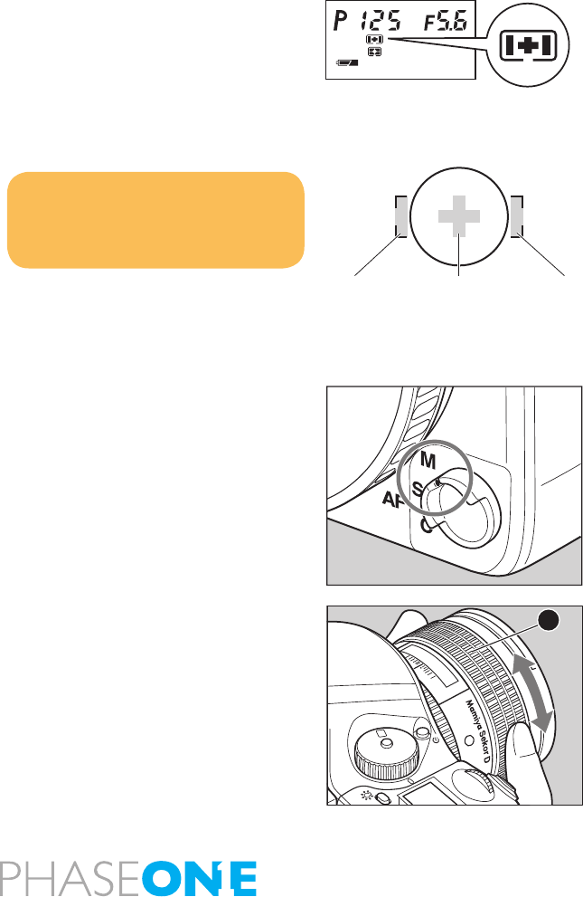
Focus Areas
You can select the focus area that best suits the kind of pictures you intend to
take. The selected focus area can be checked on the external LCD panel.
Normal focus area
Position the subject within frame in the focus fame in the viewnder.
If there are multiple objects in the focus frame located at various
distances, the camera will focus the nearest object.
Spot focus area
The camera focuses at the center of the mark in the focus frame [O] in
the viewnder.
Manual Focus Mode (M)
The auto focus function can be cancelled, and you can focus manually.
1. Switch to “M” (manual focus mode).
Turn the focus mode selector lever and set it to “M” (manual focus
mode). [MF]Appears on the top LCD panel.
2. Manual Focus Operation for Telephoto and Zoom lenses.
All Mamiya 645 AF Telephoto and Zoom lenses can be switched from
Auto Focus to Manual Focus by sliding the focusing ring on the lens
FORWARD until it clicks. When this is done, the “Auto Focus” inscription
on the lens barrel is covered and the lens can then be focused manually.
When the FOCUSING RING is set in this position the external LCD
display on the top of the camera will show. It is not necessary to set the
FOCUS MODE SELECTOR on the body to “M”. To switch back to auto
focus, simply slide the focusing ring BACK towards the camera and the
“Auto Focus” inscription on top of the lens will again be visible. This
method applies to Mamiya 645 AF Telephoto and Zoom lens only.
3. Adjust the focus.
Turn the lens focusing ring until the subject is in focus. When it is in
focus, the focusmark lights on the viewnder LCD.
Notice:
You can select whether or not to display
the focus mark and the out of focus
direction mark. Custom settings C-18.
Focus point selection mark
Left AF area Right AF area
Center AF area
X
M
Tv
Av
P
22
25
2.25
0.7
0.8
ft
m
11
4
4
CF
A
30
Manual focusing
1. Switch to “M” (manual focus mode).
Turn the focus mode selector lever and set it to “M” (manual focus
mode). Appears on the external LCD panel.
2. Manual Focus Operation for Telephoto and Zoom lenses.
All Mamiya 645 AF Telephoto and Zoom lenses can be switched from
Auto Focus to Manual Focus by sliding the focusing ring on the lens
FORWARD until it clicks. When this is done, the “Auto Focus” inscription
on the lens barrel is covered and the lens can then be focused manually.
When the FOCUSING RING is set in this position the external LCD
display on the top of the camera will show. It is not necessary to set the
FOCUS MODE SELECTOR on the body to “M”. To switch back to auto
focus, simply slide the focusing ring BACK towards the camera and the
“Auto Focus” inscription on top of the lens will again be visible.
This method applies to Mamiya 645 AF Telephoto and Zoom lens only.
3. Adjust the focus.
Turn the lens focusing ring A until the subject is in focus. When your
motive is in focus the focus mark lights in the viewnder LCD.
- When a lens with the focus mode selector is attached and the focus
mode selector lever of the camera body is set at “S” or “C”, you can
change focus modes between automatic and manual with the selector
of the lens.
- To use the auto focus function, both the camera body and the lens
have to be set in the auto focus mode.
- When either the camera body or the lens is set in the manual focus
mode, auto focus does not function.
- See the instruction manual for each lens for the way to switch focus
modes on the lens.
31
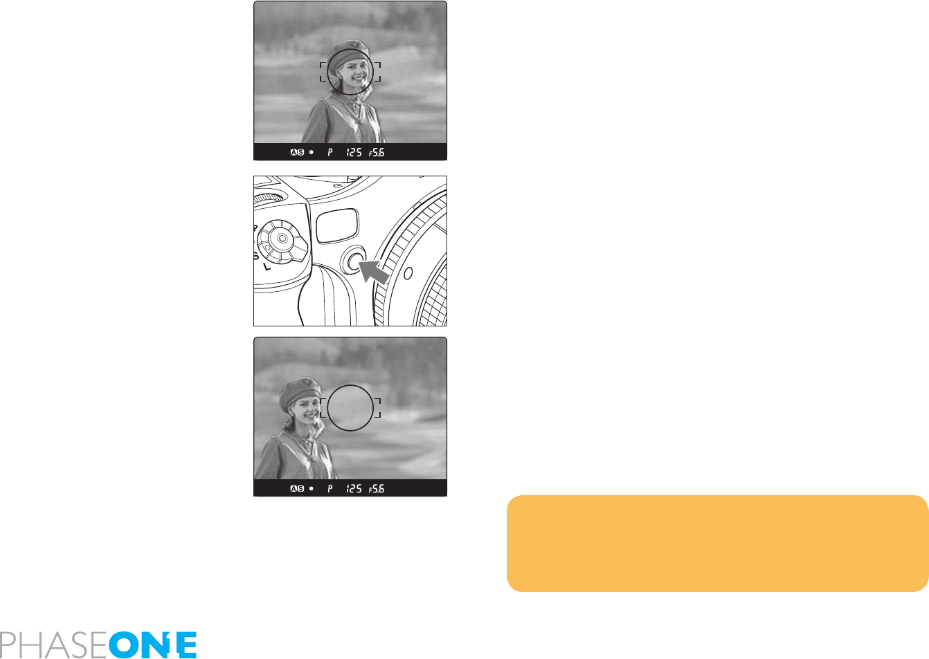
Manual focusing using the focus mark (Focus conrmation method)
With this camera, the focus mark lights in the viewnder’s LCD when
the picture is in focus. With the shutter release button half-pressed,
turn the lens focusing ring to focus on the subject. When the subject is
in focus, the focus mark lights in the viewnder’s LCD.
If is lit in the viewnder’s LCD, the camera is focused on a point behind the
object. If is lit, the camera is focused on a point in front of the object.
- Use the focus mark when taking photos in manual focus mode or
using the M645 manual lens.
- If you adjust focus using the focus mark with an M645 lens, make
sure to open the aperture. You can use this function with a lens of f/5.6
aperture or higher.
- You can set the camera so that only the focus mark is displayed.
Custom settings C-18
When Auto Focus is Failed
The auto focus function requires contrast on subject. Auto focusing may
fail to achieve focus with certain subjects described below. In such cases,
either switch to the manual focus mode and focus manually or focus an
object at the same distance as the object you want to photograph, lock
the focus using the focus lock mechanism, then take a picture.
• Low-contrast subject (blue skies, white walls and other objects)
• Two or more objects overlapping at different distances within the
focus frame (animals in cages, etc.)
• Subjects with continuous repeated patterns (building exteriors, blinds, etc.)
• Extremely backlit reective subjects (car bodies, water surfaces, etc.)
• Or when the subject is far smaller than the focus frame
in focus
turn focus ring clockwise
turn focus ring counter clockwise
32
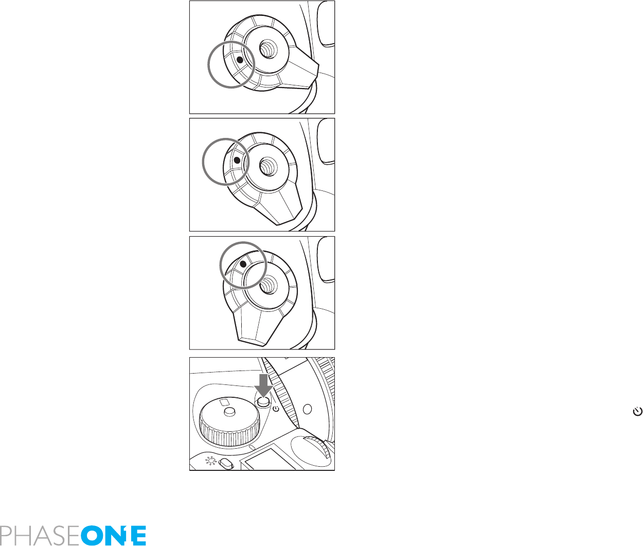
3.5 Using focus lock and infrared focusing
Using the Focus Lock Function
If the object that you want to focus on is not in the focus frame, the
camera focuses on the background at the center. In such cases use the
focus lock function to lock the focus before releasing the shutter.
1. Set the focus mode selector lever to “S” or “C.”
Put the subject in the focus frame and halfpress the shutter release button.
2. Lock the focus.
When the focus mark in the viewnder LCD is lit, press the AF lock
button on the front of the camera to lock the focus.
3. Adjust the composition.
With the shutter release button half-pressed, slide the camera to achieve
the desired composition, and release the shutter.
When the focus mode is set at “S” (single focus mode) and the focus mark
is lit, hold the shutter release button halfway down to lock the focus.
NOTE
Assignment of the AEL and AFL buttons can be swapped.
Custom settings C-15.
- You can set the camera so that when the AFL button is pressed, AF is
activated and AF lock is performed Custom settings C-19.
m

33
AF Assist Infrared Light
When the subject is dark or very low-key and the camera can fail to
auto-focus, a red lamp may light on the front of the camera when the
shutter release button is half-pressed. This light assists the camera’s
auto focus function.
Notice:
The AF assist infrared light is
emitted only when the focus mode
is set to “S” (single focus mode).
Effective range of the AF assist
infrared light is limited. It does not
reach distant subjects. - Range:
9m/29.5 ft. (using 80 mm f/2.8
lens)
When using a lens hood or a
bellows lens hood (sold as an
optional accessory) that may
interfere the assist light, set focus
before mounting the hood.
The AF assist infrared light can be
disabled. Custom settings C-26.
34
3.6 Shutter release modes
Single-Frame Mode
The lm is advanced one frame each time the shutter is released.
Set the shutter release mode selector to “S”
Continuous Mode
Photos are taken as long as the shutter release button is pressed.
Set the shutter release mode selector lever to “C”. Photos are taken
continuously at a rate depending on the buffer speed of the back
mounted on the camera.
Mirror up mode
When the shutter button is half-pressed, the mirror moves up, and when
the shutter button is pressed again, the shutter is tripped, and a picture
is taken. For the mirror up shooting procedure.
Self-Timer Mode
In this mode, the shutter will be released 10 seconds after the shutter
release button is pressed.
Turn the shutter release mode selector lever to the position.
When the shutter release is pressed, the self timer lamp will blink for 7
seconds. Then, it will blink more rapidly for 3 seconds and the camera
releases the shutter. For instructions about the self timer function.
C
S
L
M.UP
C
S
L
M.UP
C
S
L
M.UP
X
M
Tv
Av
P
22
0.8
ft
m
CF
35
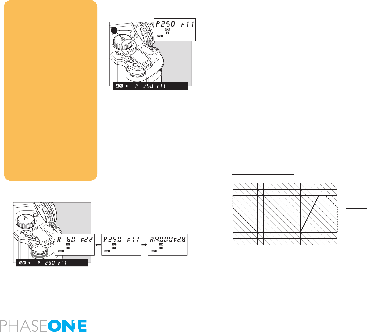
3.7 Exposure Modes
(P) Program AE
The aperture and shutter speed are determined automatically for the
optimum exposure, according to the existing ambient light. This mode
is best suited for general photography, allowing the user freedom to
concentrate on the subject.
Hold down the [program] button and turn the exposure mode setting
dial to “P” (program AE) position.
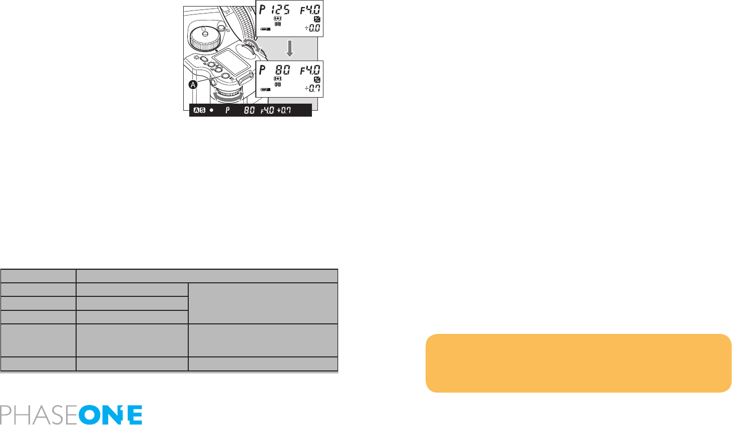
Program Shift (PH/PL)
You can change the shutter speed and aperture value by turning the
front and rear dials in the “P” (Program AE) mode. In order to avoid
blurred images (due to shaking while releasing the shutter), or to open
the aperture, change to “PH” (high speed). For slower shutter speeds
and wider depth of eld, change to “PL” (low speed). This function
allows you to make these changes quickly.
NOTICE:
If a correct exposure cannot be
obtained, the shutter speed and
aperture value blink. In such cases,
the pictures can be taken but they
may out too bright or too dark
If the shutter speed and aperture
values blink on the main LCD and
in the viewfinder display when the
program line is shifted, the proper
exposure cannot be achieved.
Please select a different Program
mode.
When the Program line is shifted, the
aperture value changes along with
the shutter speed to maintain the
proper exposure.
You can choose either aperture or
shutter-speed to give priority in
program line shift. Custom settings
C-14.
Increment of the aperture and shutter
speed can be set at either 1/3 or 1/2-
stop. Custom settings C-01.
SET
AEL
P
Av
Tv
M
X
CF
A
SET
AEL
P
Av
Tv
M
X
CF
5
4
3
2
1
0
-1
-2
-3
-4
30 15 8 4
2 1 1/2 1/4 1/8 1/15 1 /60 1/250 1/1000 1/4000
1/30 1/125 1/500 1/ 2000
6 7 8 9 10 11 12 13 14 15 16 17 18 19 20 21 22 EV
Shutter speed
(ISO100/AF80mm F2.8 D)
F
32
22
16
11
8
5.6
4
2.8
Phase One 645
program shift chart
Normal
Program shift area
36
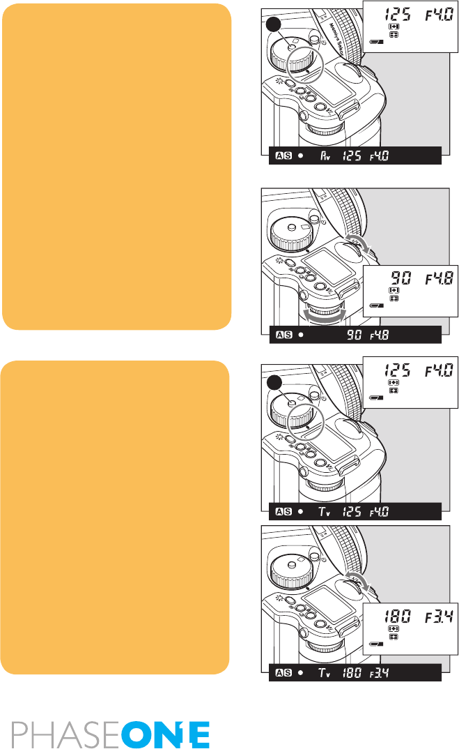
Aperture Priority AE (Av)
Set the desired aperture, and the camera selects the optimum shutter
speed accordingly. Use the Av mode to maintain specic control over
depth of eld, i.e. taking portraits or landscapes.
1. Hold down the button and turn the exposure mode setting dial to
“Av” (aperture-priority AE) position.
2. Turn the front or rear dial to set the desired aperture.
Shutter Priority AE (Tv)
Set the desired shutter speed and the camera selects the optimum
aperture accordingly. Fast shutter speed can be used to freeze motion,
and slow shutter speed can be used to blur motion on purpose.
1. Hold down the button and turn the exposure mode setting dial to
“Av” (aperture-priority AE) position.
2. Turn the front or rear dial to set the desired shutter speed.
NOTICE:
The shutter speed value will blink when
the subject is too dark or too bright for a
correct exposure. To obtain the correct
aperture, adjust the aperture value until
the shutter speed value stops blinking
and remains lit.
When the exposure is compensated with
the rear dial, the aperture can be set
with the front dial only.
Increment of the aperture can be set at
either 1/3 or 1/2-stop. Custom settings
C-01.
Rotation direction of the dials to change
the values can be altered. Custom
settings C-13.
The selected aperture level can be
locked.
Av
Tv
M
X
P
CF
SET
AEL
A
CF
M
X
Tv
Av
P
SET
AEL
NOTICE:
The aperture value will blink when the
subject is too dark or too bright for a
correct exposure. To obtain the correct
aperture, adjust the shutter speed value
until the aperture value stops blinking
and remains lit.
When the exposure is compensated with
the rear dial , the shutter speed can be
set with the front dial only.
Increment of the shutter speed can be
set at either 1/3 or 1/2-stop.
Custom settings C-01
Rotation direction of the dials to change
the values can be altered.
Custom settings C-13.
The selected shutter speed can be
locked.
Tv
M
X
Av
P
CF
SET
AEL
A
Tv
M
X
Av
P
CF
SET
AEL
37
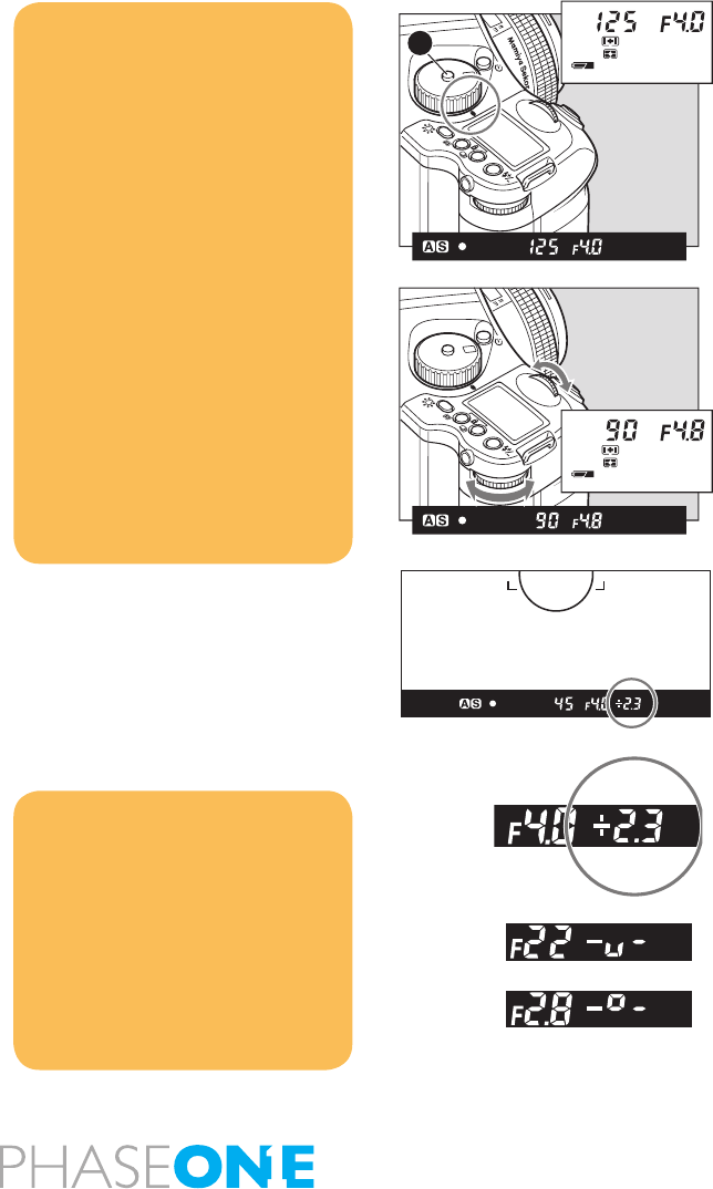
Manual Mode (M)
This mode is used to set both the aperture and shutter speed for total
exposure control. Shutter speeds can be selected from B (bulb), 30
seconds to 1/4000 of a second. Aperture values can be set from the
open to the minimum aperture. B (bulb) can also be specied in this
mode.
1. Hold down the button and turn the exposure mode setting dial to “M”
(Manual) position.
2. Turn the rear dial to set the desired aperture.
3. Turn the front dial to set the desired shutter speed.
4. When the shutter release button is halfpressed, the difference
between the present settings and the metered value is displayed in the
viewnder’s LCD panel. The value is displayed in 1/3 stop increments
within a range of ±6 EV.
CF
M
X
Tv
Av
P
SET
AEL
A
NOTICE:
When the exposure is compensated
in the Manual mode, the difference
between the metered value and the
compensated value will be displayed
on the viewfinder LCD. In the B
(Bulb) mode, the difference with the
metered value is not displayed.
Increment of the aperture and shutter
speed value can be set at either 1/3
or 1/2-stop. Custom settings C-01.
The assignments of the front and
rear dials can be swapped. Custom
settings C-11.
Rotation direction of the dials to
change the values can be altered.
Custom settings C-13.
The selected aperture and shutter
speed can be locked.
CF
M
X
Tv
Av
P
SET
AEL
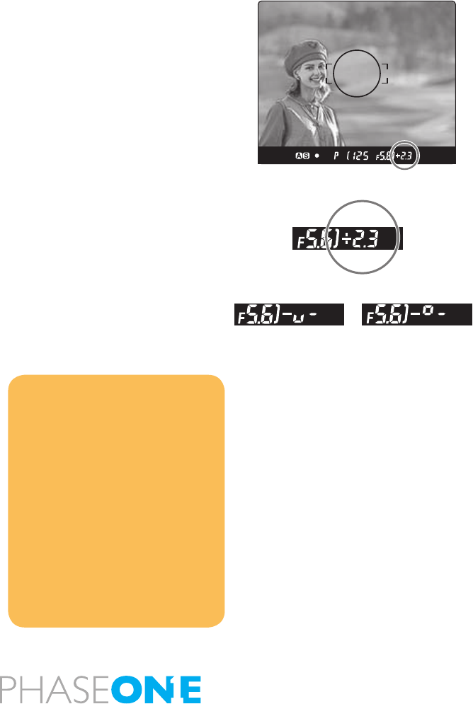
Notice:
When the set value matches with
the metered value, the difference
indicator will show “0.0”. When the
difference between the set value
and the metered value is greater
than ±6EV and the set value is lower
the metered value, the indicator
in the viewfinder LCD shows “– u
–.” Contrarily when the set value is
higher than the metered value, the
indicator shows “– o –.”
38
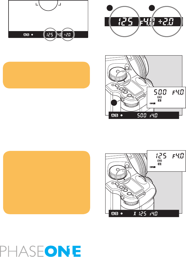
One-push shift function
When difference between the set value and metered value is displayed
on the viewnder LCD in the Manual “M” mode, press the AEL button
for approx. 1 second and the camera will automatically adjust the
shutter speed to achieve the correct exposure based on the set aperture
value.
While the difference [B] between the set value [A] and the metered
value is displayed on the viewnder LCD, press the AEL button [C] for
approximately one second. The camera changes the shutter speed to
an appropriate level.
X Mode (X)
Select this mode when you use a ash. The shutter speed will be xed
at 1/125 second for synchronization.
CF
M
X
Tv
Av
P
SET
AEL
C
Notice:
The aperture level can be selected
for the parameter to shift. Custom
settings C-20.
Notice:
The selected aperture value can be
locked.
The synchronizing speed can be
changed. Custom settings C-23.
When you take a photograph with
TTL light metering with a Metz flash.
X
M
Tv
Av
P
CF
SET
AEL
A B

39
3.8 Flash photography
Phase One 645 AF is equipped with a horizontal local-plane metal
shutter; this makes it unnecessary for the user to acquire lenses
equipped with central shutters, though it still is possible to use these
lenses optically.
The focal-plane shutter provides higher shutter speeds, compared to
central shutter lenses, which allow you to freeze a fast moving target by
using very high shutter speeds.
When using a focal-plane shutter it is not possible to achieve ash
synchronization faster than 1/125sec, as the 2 shutter blades at e.g.1/500
are moving parallel creating a small slit allowing a small fraction of the
light to enter the sensor area of the digital back. This shutter method
allows for shutter speeds of up to 1/4000 sec.
A central shutter will make it possible to achieve slightly higher shutter
and ash sync speeds, but central shutters but will not be able to
achieve high shutter speed.
1. To use a grip type ashgun or a strobe with other electric contacts
than X contact, connect the sync. cord to the camera’s sync. terminal.
(See note below about ashes designed exclusively for other camera
makes.)
2. While pressing the unlock button, turn the exposure mode setting
dial and set it to “X” (1/125 sec.) or “M” (manual). When “M” (manual)
is selected, turn the front dial and set the shutter speed to 1/125 sec.
or slower.
3. Turn the rear dial to set the aperture, and then take the picture.
In addition to its standard ash sync system, the Phase One 645 AF
features TTL (through the lens), off the lm (OTF), electronic ash
exposure metering.
NOTICE:
This camera’s synchro contact is an
X contact.
Using flashes designed exclusively
for other makers of cameras may
damage the camera’s internal
mechanisms if connected to the
camera’s hot-shoe. In this situation,
use an off-camera flash bracket and
connect a sync. cord to the camera’s
synchro terminal.
When using flashes with a flash
duration of 1/500 sec. or longer, set
the shutter speed to 1/30 sec. or less.
40
A ash sensor located inside the camera body reads the ash
reected off the lm surface at the moment of exposure. The sensor
is connected via the Phase One 645 AF s dedicated hot-shoe to a
shoe- or handlemount style Metz ash unit via the Metz SCA 3952 TTL
Adapter. Maximum ash sync speed is 1/125 sec., making daytime
synchronization possible.
The ISO of the ash is automatically set through the TTL connection
from the camera’s Film Magazine; any adjustment to this is instantly
recognized after the setting is locked and the shutter release is half-
pressed. Also, when Film Magazines with different ISO settings are
switched on the camera body, the TTL ash connection instantly
recognizes the change.
To utilize the TTL ash feature with all TTL-operable Metz ash units,
a Metz SCA 3952 Module is required. Please see the chart below for
compatibility and/or additional adapters that may be necessary.
The resulting ash exposure automation determines correct ash
exposure and automatically adjusts the output of the ash. It also
automatically corrects for exposure compensation normally required
when using lters, close-up bellows or extension tubes. However, as
with all TTL systems, it requires manual compensation for differences
in lm surface reection characteristics. The amount of compensation
is determined by experimentation and is performed on the Mamiya Film
Magazine ISO setting.
1. Mount the SCA3952 adapter onto the Metz ash, insert fully into the
camera’s hot shoe, and then tighten with the locking knob.
2. Set the exposure mode, and then check the shutter speed and
aperture.
Type of flash SCA3952 Module Converter
Metz 44 MZ-2 shoe-mount x
Metz 54 Mz-3 shoe-mount x
Metz 45 CL-3 & 4 Handle-mount x SCA 3045
Metz 60 CT-4 Handle-mount x SCA 3000
Metz 70 Mz-5 &4 Handle-mount x
Adapter
Metz Flash Unit
A
For more info on Metz, contact the local Metzdealer or www.metz.de
41
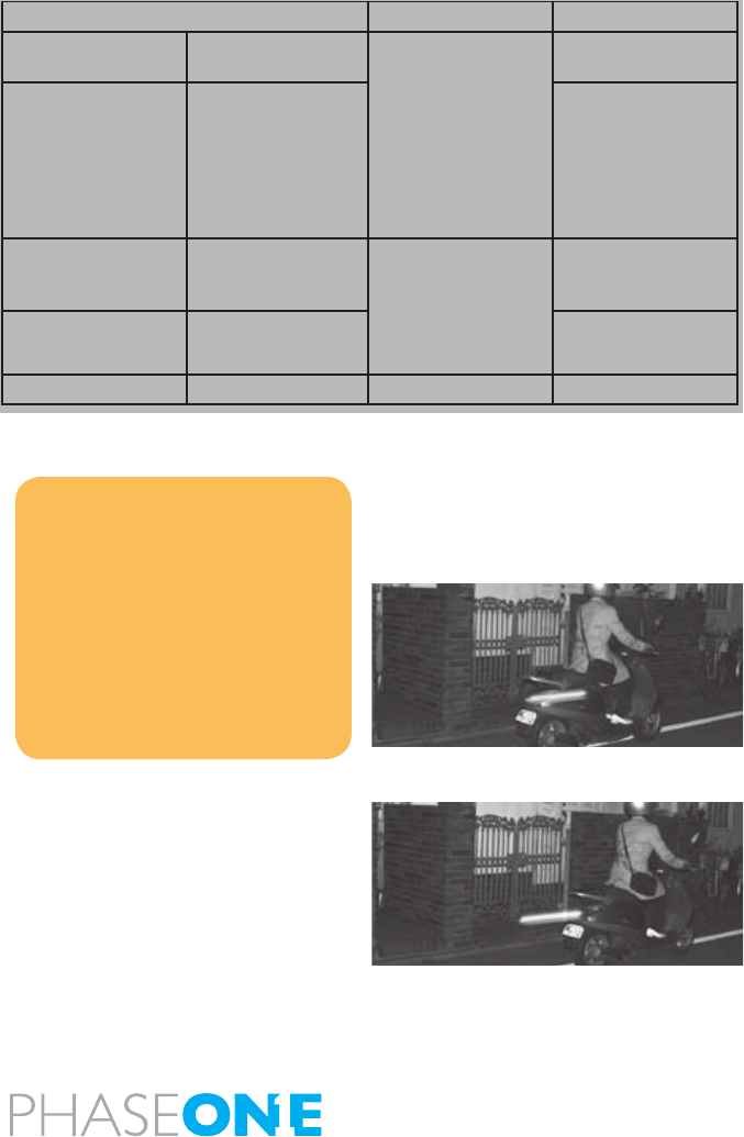
Example:
(1) When the size of the subject you want to light with the ash is
relatively small within the picture
(2) When the background behind the subject is extremely bright or when
there is a strongly reective object in the background
(3) When the background behind the subject is extremely dark (outdoors
at night, etc.)
(4) For ash photography with a narrow lm latitude
1. While in the P or Av modes, the camera can be set to release the
shutter at the metered value, even the background behind the subject
is dark. Custom settings C-24.
2. The sync. speed in the X mode can be set between 1/40 and 1/125
seconds. Custom settings C-23.
* When the shutter speed is set to 1/2 increments, the sync. speed can
be set between 1/45 and 1/125 seconds.
Rear Curtain Syncro
When a moving subject has been shot under this function, the ash of
light appears after the moving subject.
Rear curtain sync mode
Front curtain sync mode
This function is set by Custom function setting.
Custom setting C-27.
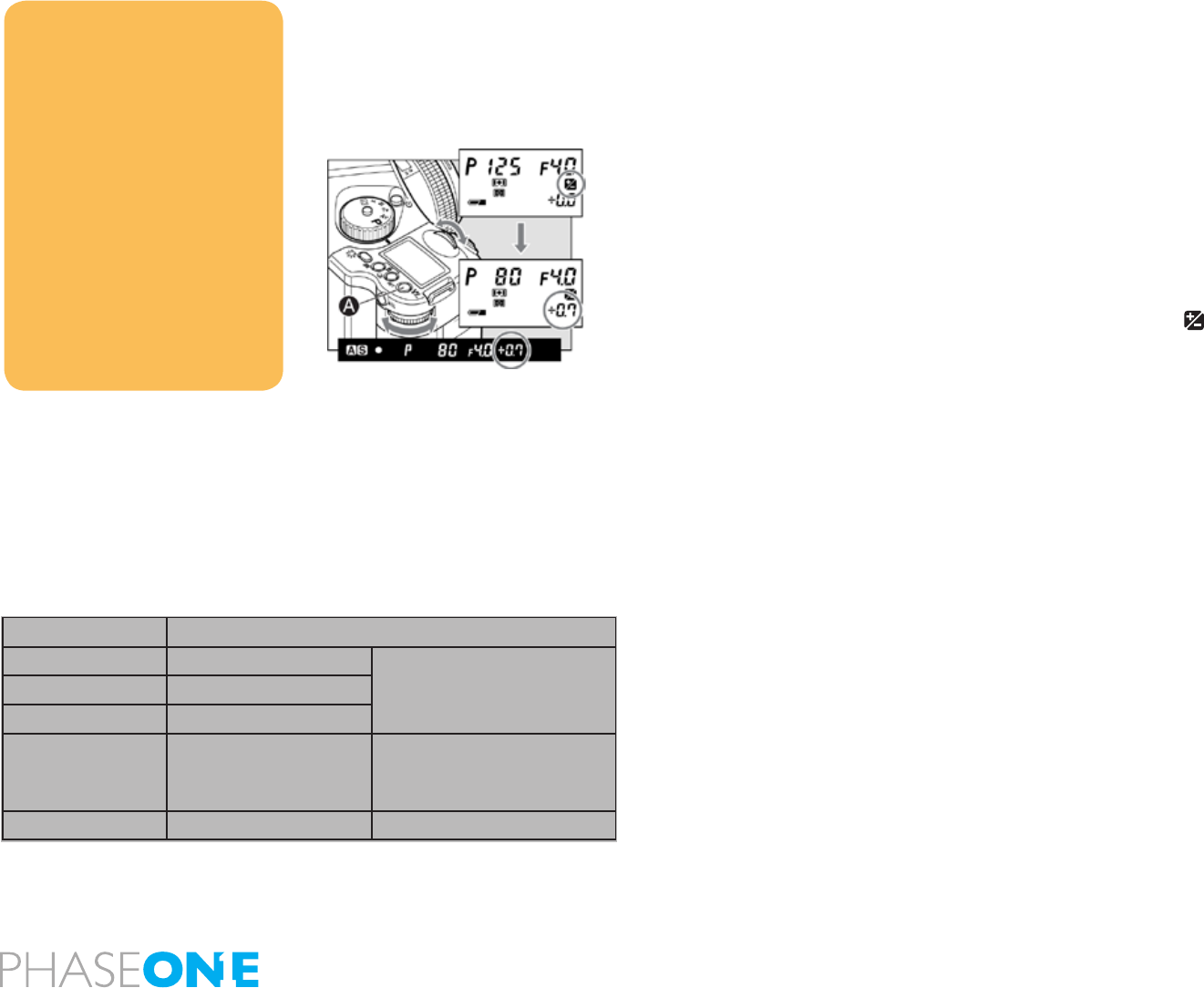
Exposure mode Shutter speed Aperture
P Program AE Automatically set by
camera to 1/60 sec.
when the metered
shutter speed is 1/60
or slower, and 1/125
when it is 1/125 sec.
or faster.
Automatically set by
camera
Av Aperture priority AE Any aperture
Tv Shutter priority AE Automatically set
by camera to 1/125
when the set shutter
speed is 1/125 sec.
or faster.
Automatically set by
camera
M Manual mode Any aperture
X Synchro mode 1/125 sec. Any aperture
NOTICE:
With TTL flash photography, the
reflection of the flash is metered
and the intensity of the flash is
adjusted automatically, so TTL flash
photography may not be able to
suit to all conditions. In the cases
described below, we recommend
that you use a flashmeter to check
the intensity of the flash or to use a
manual flash setting.
42
3.9 flash compensation settings
By combined use of a Metz ash and the SCA3952 adapter, the camera
adjusts for ash. It can be adjusted within ±3EV in increments of 1/3
steps.
1. Turn on the power
Install the SCA3952 adapter on the Metz ash, and put it on the camera
then lock the ash in place using the locking knob on the ash shoe.
Turn the shutter release mode selector lever to the “S” or “C” position,
and turn ON the ash power switch.
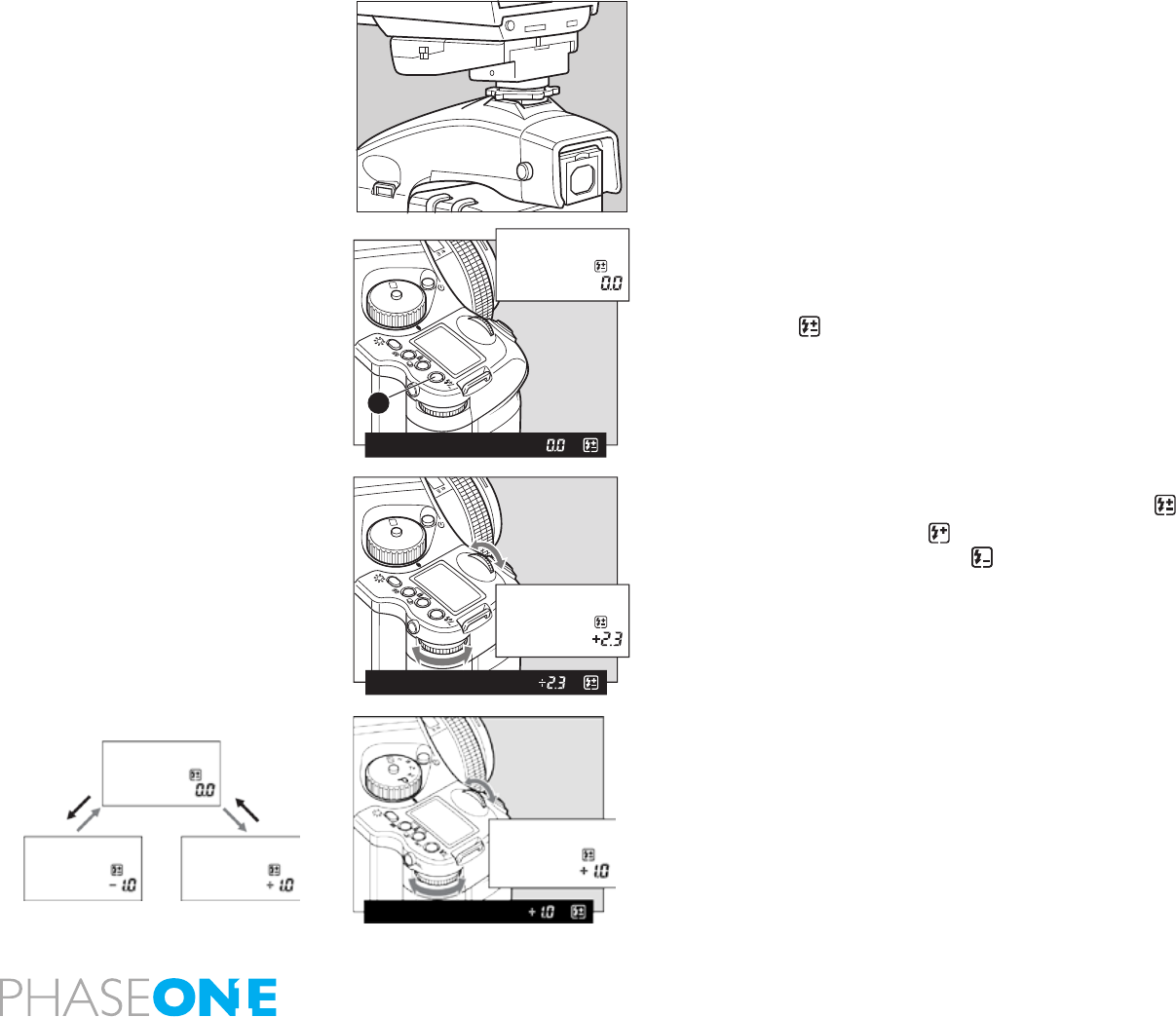
2. When the ash charge conrmation lamp lights, press the set button
A in. The is displayed on the main LCD panel.
3. Turn the front or rear dial to select the ash compensation value.
External LCD Panel (normal display)
4. When the shutter button is half-pressed, the display appears on
the external LCD, and appears on the LCD inside the viewnder
with a + compensation, or appears with a – compensation.
Viewfinder LCD readouts
- If the ash-charge mark is not displayed, the ash compensation
button [A] can not be used.
- Keep pressing the set button to activate the ash compensation
mode. You can check the exposure compensation value.
- If you turn the shutter release mode selector lever to the “L” (power
OFF) position, the compensation value will be canceled.
Exposure compensation and ash compensation can be linked.
Custom settings C-25.
SET
AEL
P
Av
Tv
M
X
CF
A
SET
AEL
P
Av
Tv
M
X
CF
43
4.0 Advanced functions
4.1 Exposure Compensation
In some situations, such as a great difference between the subject
and background brightness or overall subject tones that will not meter
correctly because they are all black or white, the resulting photograph
may be under- or overexposed. When this occurs, use the exposure
compensation function. Exposure compensation can also be used
when you want to intentionally create overexposed or underexposed
pictures. Please keep in mind; you can do quite a lot of work using the
High Dynamic Range Tool in Capture One 4.
With the exposure compensation dial
1. When exposure compensation button A is pressed, a ppears
on the external LCD. When the front or rear dial is turned counter-
clockwise, the exposure is increased; conversely, when it is turned
clockwise, it is decreased. The exposure compensation value can be
checked on the external LCD or LCD inside the viewnder.
2. After taking the pictures, press exposure compensation button A
again to return the exposure compensation value to 0. The exposure
compensation value mark on the external LCD is cleared, and the
exposure compensation function is released.
NOTICE:
After taking pictures using the
exposure compensation feature,
be sure to return the exposure
compensation dial to the “0” position.
The exposure compensation dial is
locked at the “0” and positions.
The exposure compensation feature
is available during AE locked
operation.
The width of the exposure
compensation step can be changed.
Custom settings C-01.
The maximum amount of the
compensation can be set either at ±3
or ±5. Custom settings C-05.
Exposure mode Exposure compensation display
PProgram AE
The set value is displayed
Av Aperture Value Priority
Tv Time Value Priority
MManual Mode
The difference between the
metered value and the set
Exposure value is displayed
XSync Mode Not displayed
44
4.2 AE Lock
Shooting with the AE lock function is useful in cases where the subject
to be brought into focus differs from the subject whose exposure is to
be measured or when measuring the exposure of a particular part to be
brought into focus using spot exposure metering mode while that part
is on the shooting screen.
The AEL button will lock the Auto-exposure value as the photo is being
recomposed.
1. Turn the shutter release mode selector lever to “S” or “C.”
2. Turn the exposure mode setting dial and select any of “P,” “Av,” or “T”.
3. Focus on the subject for metering exposure, and press the AEL
button on the rear of the grip. [ ] Will appear on the viewnder LCD,
indicating that the exposure value is locked.
4. Slide the camera to recompose the shot, and take the picture.
SET
AEL
P
Av
Tv
M
X
CF
A
NOTICE:
[ ] in the viewfinder LCD blinks to
indicate the exposure is locked, when
you continue to take the next picture
in the AE lock mode.
NOTICE: If you turn the shutter
release mode selector lever to the “L”
(power OFF) position, or after elapse
of one hour, the AE lock mode will
automatically be cancelled.
NOTICE: In the Manual “M” exposure
mode, you cannot use the AE lock
function. When the difference
between the metered value and the
set value is displayed, press the
AEL button for approximately one
second, and one-push shift function
will be activated and the camera
will automatically adjust the shutter
speed.
45
Metered-value difference indicator
Keep pressing the AEL button and the difference between the
metered exposure value and the exposure of the new composition
will be displayed on the viewnder LCD. This function can be used
to see if an object of very different brightness levels can be properly
photographed.
If the difference between the set value and the metered value exceeds
6EV, the viewnder LCD blinks “– u –” for underexposure and “– o – ”
for overexposure.
By turning the front or rear dial in the AE lock mode, you can change
the aperture and shutter speed value without changing the exposure
value that is set when entered into AE lock mode.
In the “P” mode (Program AE) mode, turning either the front or rear dial
shifts the program to “PH” and “PL.” When in “Av” (Aperture-priority
AE) or “Tv” Shutterpriority AE), turning one of the dials changes both
the aperture and shutter speed values.
NOTICE:
The way to cancel the AE lock can be
changed. Custom settings C-17.
Half-pressing of he shutter release
button can activate the AE lock
mode. Custom settings C-16.
The assignment of the AEL button
and AFL button can be swapped by
using Custom settings C-15.
Exposure compensation and auto-
bracketing function can be used
when the camera is in the AE lock
mode in normal operation or with the
mirror locked up.
46
4.3 Auto Bracketing
With auto exposure bracketing, you can capture different exposure
variations automatically for three or two successive frames, when it is
difcult to determine an exposure compensation value. The number
of frames to be taken, the bracketed shooting sequence, bracketing
margin and other settings can be selected as desired for shooting in
auto bracketing mode.
1. Turn the shutter release mode selector lever to the “S” or “C”
position.
When set at the “S” position, you can shoot one frame with each press
of the shutter release button. In the “C” mode, the camera takes three (or
two) frames successively with one press of the shutter release button.
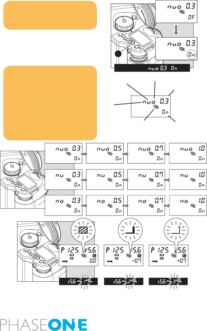
2. Keep pressing the auto-bracketing button for approximately one
second, the auto bracketing mark will blink on the top LCD panel. Turn
the rear dial before this indicator goes out, and change “OF” on the
display to “On”.
3. While the auto bracketing mark is blinking, turn the front dial to
change number of frames (3 or 2), sequence of the shots in 2-shot
mode (shown above), and increment (1/3, 1/2, /2/3 or /1-stop).
4. Press the shutter release button.
When the shutter button is pressed in auto bracketing mode the
shooting sequence and auto bracketing mark blink on the LCD inside
the viewnder. Furthermore, the auto bracketing mark blinks, the
bracket step width is displayed, and the shooting sequence can be
checked on the external LCD.
5. After taking pictures, press auto bracketing set button A, turn the
rear dial, set auto bracketing mode to “OF,” and release.
Then press the auto bracketing set button or half-press the shutter
button to return to the normal display mode.
NOTICE:
When you want to cancel the auto-
bracketing mode, turn the rear dial to
change “On” to “OF”
SET
AEL
P
Av
Tv
M
X
CF
A
SET
AEL
P
Av
Tv
M
X
CF
SET
AE L
P
Av
Tv
M
X
CF
Underexposure
Bracketing Margin
Overexposure
Auto Bracketing Icon
Standard
Setting selection
NOTICE:
The letters (n, u, o) indicate the type
of exposure (“n” for normal, “u” for
underexposure and “o” for over-
exposure) and numbers indicate
increment (0.3 for 1/3, 0.5 for 1/2, 0.7
for 2/3, and 1.0 for 1/1)
By pressing any other button or
leaving the camera for 5 seconds,
setting for the auto bracketing
will be stored.
OverexposureNormal exposure Underexposure

47
Single-Frame Mode (S)
Press the shutter release button for each shot.
The camera meters adequate exposure value for each shot and
performs auto-bracketing. The camera stays in the auto-bracketing
mode until the last frame of the roll lm is exposed or you cancel the
auto-bracketing mode manually.
Continuous Mode (C)
By pressing the shutter release button once, the camera takes 3 (or
2) shots in series. With each press of the shutter release button, the
camera repeats auto-bracketing. The standard (normal) exposure value
will be xed when you take the rst frame.
When the number of available frames of the current lm is less than 3
(or 2) in the auto-bracketing mode, the “– no – ” mark blinks and the
camera automatically cancels the auto-bracketing mode. When you
want to cancel the auto-bracketing mode, turn the rear dial to change
“On” to “OF”.
NOTICE:
If you turn the shutter release
mode selector to the “C” position
before taking three (or two) frames,
the camera will restart the auto-
bracketing from the initial frame
(normal exposure in the default
setting).
NOTICE:
Order of the exposures in 3-shot
auto-bracketing can be changed.
Custom settings C-10.
The way to cancel auto-bracketing
mode can be changed. Custom
settings C-11.
Exposure Mode Setting
PProgram AE Shutter speed varies
Av Aperture Priority AE Shutter speed varies
Tv Shutter Priority AE Aperture varies
MManual Mode Shutter speed varies
XX-sync mode No setting
AE settings under auto-bracketing mode
48
4.4 Taking photos with the mirror up
This function prevents mirror-caused vibrations which may blur the
image in close-up photography, when shutter speed is slow, when a
telephoto lens is used, or when photographing a poster or another
picture.
When using the mirror-up, Electromagnetic Cable Release RE401
(optional) is recommended.
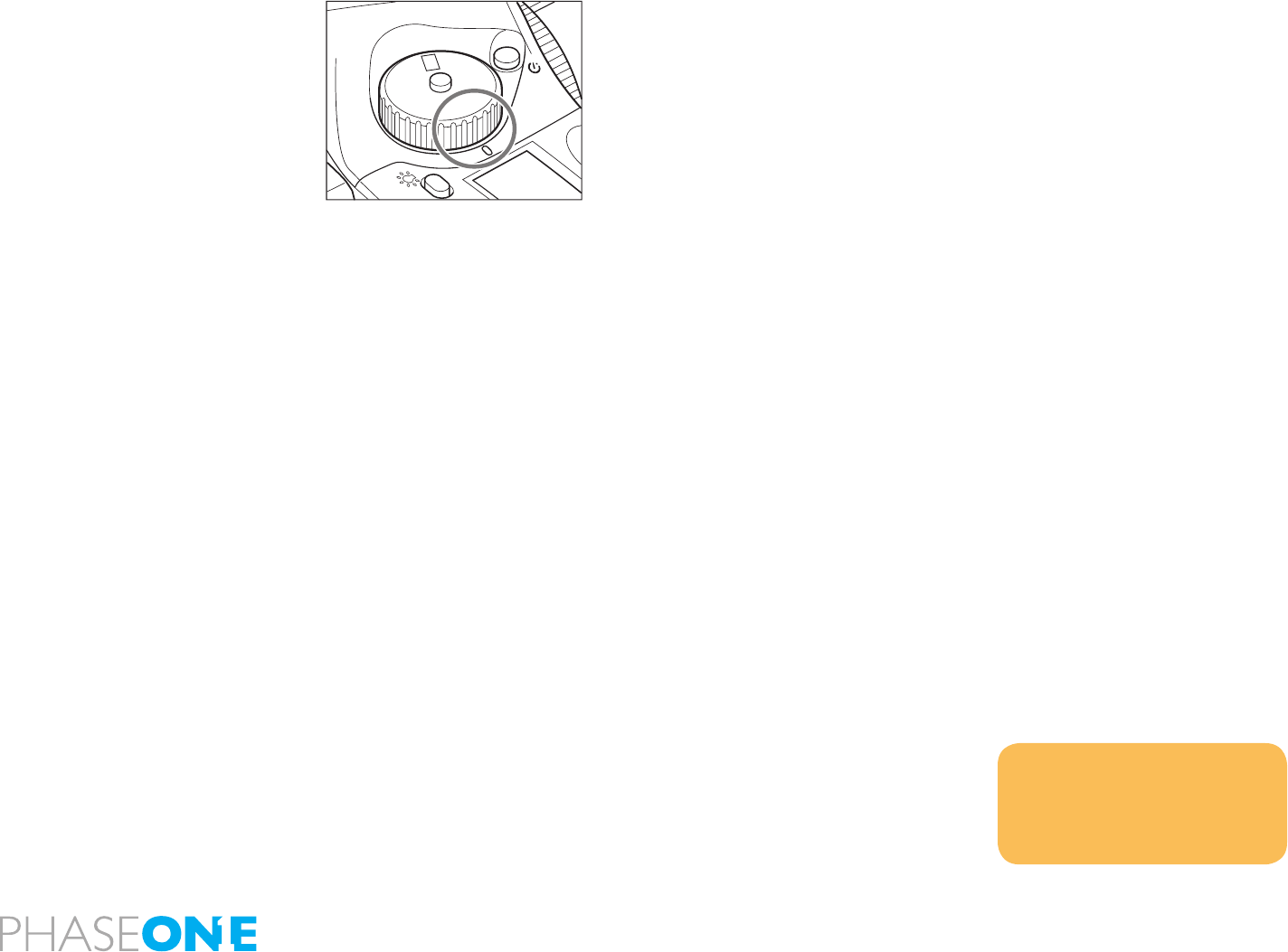
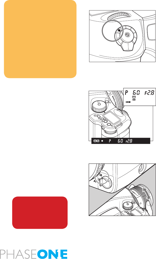
1. Set the drive dial to “M.UP”
2. Select “S” (single focus mode) by turning the focus mode selector lever.
3. Turn the exposure mode-setting dial to choose any of “P”, “Av” or
“Tv” exposure mode.
4. Focus the subject, and determine composition and exposure
5. The mirror moves up when the shutter button is fully pressed.
6. Pres the shutter button again to take pictures.
In the manual mode
1. Set the focus mode selector lever at “M” (manual focus mode)
position. Turn the lens-focusing ring to focus.
2. Determine the exposure, focusing and frame structure by pressing
the shutter release button halfway while looking into the view nder.
3. Lock the mirror up by pressing the mirror-up button.
NOTICE:
Auto bracketing exposures can be
made when the auto bracketing
mode is set before taking photos with
mirror up.
The mirror goes back to the normal
position in 30 seconds. This can
be changed to 60 seconds or no
limitation by the custom function .
(See page 89) Keeping the mirror up
consumes more power.
The mirror will return to the original
position if the lens is removed from
the camera body.
M
.UP
C
S
L
SET
AEL
P
Av
Tv
M
X
CF
WARNING:
DO NOT point the lens at
the sun during the mirror
up mode. The sun’s intense
light can scorch and
damage the shutter curtain.
22
25
2.25
0.7
0.8
ft
m
11
4
4
P
Av
Tv
M
X
CF
49
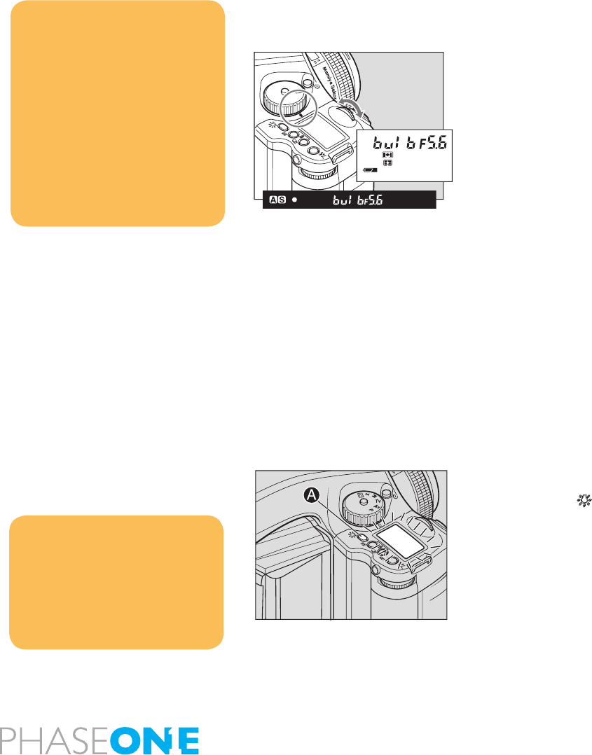
4.5 Long exposure - Bulb Mode
To expose lm longer than 30 seconds, adjust the shutter speed to
“B” (bulb). In order to prevent camera shake, use an electromagnetic
shutter release and tripod.
1. While pressing the unlock button, turn the exposure mode dial and
set it to “M” (manual mode).
2. Turn the front dial to select “bulb”, then turn the rear dial to set the
aperture.
3. Determine the composition, focus, and then take the picture. The
shutter remains open as long as the shutter release button is pressed.
4.6 Camera display light
To see the top display at night or in dark places, press the backlight
button A/ .
The backlight will go on approximately 10 seconds and go off unless
there is another operation.
When operating the camera while the backlight is on, the backlight will
be lit for approximately another 10 seconds.
CF
M
X
Tv
Av
P
SET
AEL
NOTICE:
When releasing the shutter, or
pressing the backlight button A/
while the backlight is on, the
backlight will go OFF.
The backlight can be set to turn on
during the camera is holding metered
value. Custom settings C-06.
NOTICE:
As the camera is electronically
controlled even during exposures, it
is recommended to replace batteries
before bulb exposure.
Normally the camera can take a
picture with a bulb shot up to 60
minutes. However, the bulb shot time
can be changed from one minute to
infinite. Custom settings C-21.
It is possible to set the camera as
the shutter remains open until the
button is pressed once again. Custom
settings C-22.
50
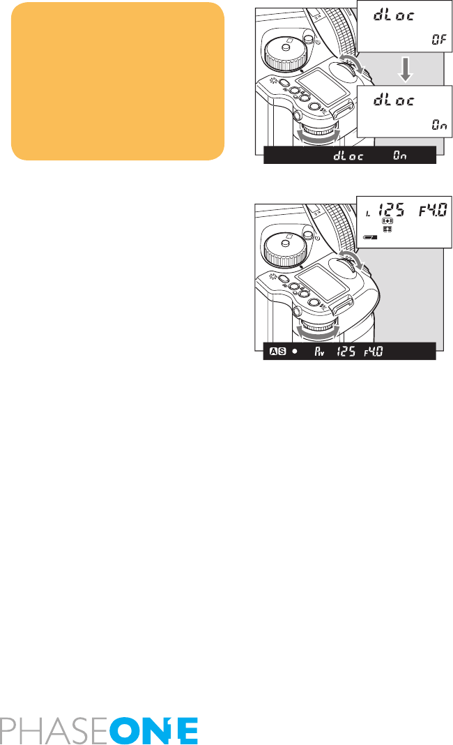
4.7 Front/rear dial lock mechanisms
When the Electronic Dial Lock is “On,” all currently set values in “Av”
(Aperture Priority AE), “Tv” (Shutter Priority AE) and “M” (Manual mode)
cannot be adjusted with the front or rear dials. This prevents accidental
change of shutter speed or aperture values.
Press down both the multiple exposure mode button and the auto
bracketing mode button for approximately one second, until the “On”
indicator blinks.
To release the mode, hold down the same buttons until “OF” blinks.
3. “L” is displayed on the main LCD to indicate that operation of the
front and rear dials is blocked.
When the dial lock is ON, the shutter speed and aperture will not change
even if you turn the front or rear dial.
When you activate the electronic dial lock, and if you then operate the
electronic dial, the dial lock indicator “L” on the main panel blinks for
three seconds to show that the electronic dial lock is functioning.
Av
Tv
M
X
P
CF
SET
AEL
NOTICE:
The setting will be stored after one
second.
Dial lock can not be set when the
exposure mode is “P” (program AE).
Even while dial lock is set, the front
dial or rear dial can still be used to
perform the various settings. (Dial
lock is temporarily released.)
Av
Tv
M
X
P
CF
SET
AEL
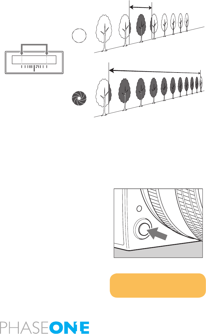
51
4.8 Depth of field
Depth of eld (D.O.F.) is dened as the zone of sharpness before and
behind the plane of focus. It depends on distance to subject, focal
length of lens, aperture setting and distance the lens is focused at.
In addition to visual observation via the depth of eld preview button,
the D.O.F. can be determined by using the depth of eld scale on each
lens. The f/stop numbers appear on both the right and left side of the
white index mark in the center of the scale. Simply read the gures
which appear above the f/stop numbers on the distance scale of the
lens. (see illustration below)
Depth of Field Preview Button
When the preview button is pressed in, the depth of eld for the aperture
set on the camera can be checked by looking through the viewnder.
After focusing, press the preview button. The diaphragm will be stopped
down to the set aperture.
NOTICE:
While operating the preview button,
you cannot release the shutter
When the aperture is open (the subject depth is small)
When the aperture is stopped down (the subject depth is large)
1.5
22 2211 114 4
1.51.2 2
54 7
ft
m
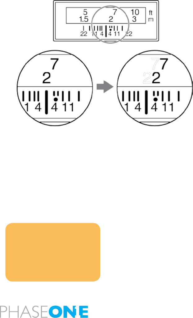
52
4.9 Infrared photography
Infrared Photography is complicated when using digital backs, as the
digital back is adjusted to match the viewable light perfectly. To make
good infrared photography, you need the back adjusted for this or a back
dedicated to infrared photography. DO NOT TRY THIS AT HOME
– all corrections in this area must be done by Phase One to ensure the
precision. If you remove the protectionglass or make other physical
adjustments on the back the warranty will immediately be annulled.
If you consider Infrared Photography, please contact your local
Phase One dealer for technical advice and pricing on this.
When taking photos using infrared lm, the position at which the subject
is in focus is slightly different than that of regular lms. This is because
the infrared rays have a longer wavelength and the image converges
behind the lm plane of regular lm. Use the procedure described
below when taking photos using infrared lm.
1. Set the focus as usual. Read the point on the distance scale matching
the center index of the depth scale.
2. Set the focus mode selector lever to “M” (manual focus mode). Turn
the focusing ring clockwise and align the read point to the infrared
index.
NOTICE:
Use a red filter when taking photos
using infrared film.
Be sure to read the infrared film’s
usage instructions.
You cannot take photos in AE modes
when using an infrared film.

53

54
5.0 Tethered shooting
Tethered photography with Phase One is as easy as plug and play can
be, even though the quality and technology is advanced, it is created to
match all studio environments.
5.1 Connecting
Connect the Fire-wire cable to the back of the camera and on the back
of your Mac or WinPC – though there can be found computers with Fire-
Wire plug-ins on the front, our experience is that the back connection
is more stable, and functions better. Capture One will automatically
recognize the camera, and settings shared, read more on capturing in
the software manual.
5.2 Driver set-up
Install Capture One on your computer, follow the instructions provided
with the software, and activate the software.
There is no specic program set-up except the set-up or recommended
hardware provided in the beginning of this user guide as well as in the
user guide for Capture One.
Eventual rm ware announcements will be available on our website,
and in our newsletters.

55
5.3 Tethered operations
When operating in a studio, connected to a computer via FireWire you
are not dependent on battery power or storage media. You can capture
directly to the Phase One Capture One Raw workow software on
either Mac or PC, providing power to the P+ back via FireWire without
the battery or CF-card inserted.
When operating tethered you have the option of capturing the images
to the CF-card or transferring captures directly to the currently assigned
capture folder in the Capture One application on the computer hard
disk.
The display on the P+ back can either be turned off while shooting
tethered or set to display the images while they are shot, just as if
shooting untethered.
When unplugging the P+ back from the FireWire, the P+ back will default
to untethered mode, capturing to CF-card or microdrive, and using the
battery for power.
Also when capturing tethered to a laptop with 4 pin mini 1394/FireWire
without power it will require a battery in the P+ back.
With the (non P+) P 20 and P 25 it is necessary to use the Phase One
“No Firewire Power Solution” Part.# 70508 to force battery power.
Using the four menu buttons you can setup the preferences for all these
operational features.
Consult the Capture One 4 manual for detailed intro to the software
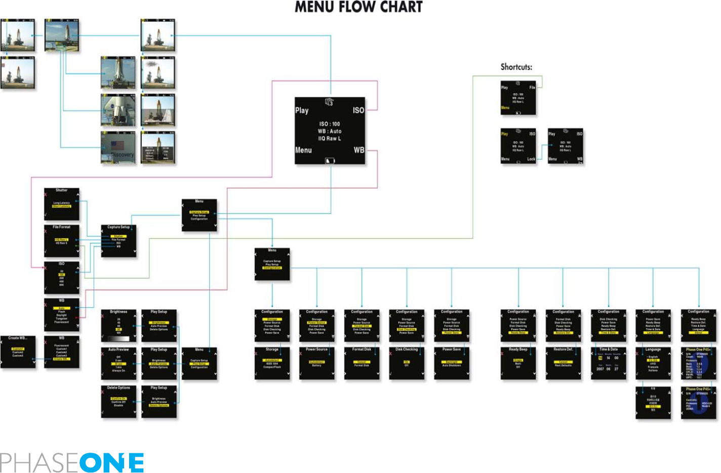
56
6.0 The Back
The back is a highly developed piece of electronic. The Phase One backs
are created to provide a natural and easy workow, without creating
unnecessary complicated functions or menubrowsing. You can see the
menuowchart here and read more on the menuoptions in this chapter.

57
6.1 CF card usage
When working with CF-cards, card readers and digital cameras it is
very important to follow a few rules, to avoid loss of data.
Phase One recommends that you test-drive all new Compact Flash™ cards
(including the one enclosed). By doing an initial test to verify that the capture
les are stored properly on the card and can be accessed on a computer
you will avoid unpleasant surprises on location or when you return from
a job. Compact Flash™ cards are manufactured by other suppliers, and
Phase One cannot guarantee that the cards are not defective.
Inserting and ejecting cards on the P+ back
The compact ash card or microdrive is inserted in the hidden slot
located under the cover on the left hand side of the P+ back.
Insert the card with the brand label facing the display end of the digital
back as shown in the image.
When the card is inserted no parts are sticking out, the cover can be closed.
To eject the card push the small button just above the card once, and
an ejecting pin will come out.
Pushing this pin all the way back in will eject the card.
Always format your Memory card in the P+ back in general all CF-cards
or microdrives comes preformatted and ready to use in the P+ backs.
However to ensure the best performance from these cards it is to be
considered best practice to always format them in the P+ back.
Formatting of the memory card is done in either FAT 16 or FAT 32
depending on card size, and if the formatting is done in the P+ back
cluster sizes on the disk is set for best performance.
It is however also possible to format the cards on either Mac or Windows,
this is explained in the following sections of this chapter.

58
CF card usage – 3S the Secure Storage System
When a card is inserted into the P–back, a complete disk check for a
valid le structure is performed.
For normal CF-cards you will not even notice the extra time it takes
larger cards will of course take slightly longer to load
Large Microdrives are experienced as slow, but a progress bar showing
the status if the time exceeds 2 seconds
The progress of a disk check is indicated with series of small dots in
the disk icon.
It is not recommended to turn off disk checking, but it is possible by
selecting the “Disk Checking” available in the “Menu” under “Storage”.
Whenever Disk Checking is turned off the capture counter turns red to
indicate that the disk has not been checked.
Disk Check summary
With the 3S technology we have created a new and safe storage system
in the P – back that is much more rugged than anything else seen in
the industry.
• We now offer full formatting support in the P – back (no more need for
formatting on the computer)
• Damaged or wrong formatted cards will be detected immediately, and
we now also have the ability to reformat the cards to correct them.
• Ejecting a card while in a writing session will not damage the le
structure of the entire CF-card, only the image being written and the
images in the buffer can be damaged.
• No other digital back or DSLR camera has this level of storage security!

59
6.1 CF card usage in general
Ejecting the card while the P+ back is still writing to the card (red LED
is on) will cause images that are still not written to the card, to be lost
or damaged.
Also, ejecting the battery while the P+ back is still writing might result in
loss of the data that is not yet written to the memory card.
For rescue tips in situations where the P+ back reports that you have a
damaged card, please see “Sandisk card and Card reader” section.
General handling guidelines
Especially when using microdrives you have to be careful not to drop
them on the ground or even on a table.
Compact ash cards are not as vulnerable as microdrives. Please
keep the card away from moisture and sand and don’t bend it. Use the
supplied jewel box as a storage container for the card.
Using cards in the card reader
When inserting the card into the card reader on a Mac or PC, the card
will be mounted as a removable drive on the computer.
For information on how to import the les to Phase One Capture One,
please consult the Capture One online user guide available under
“Capture One Help” in the Help Menu.
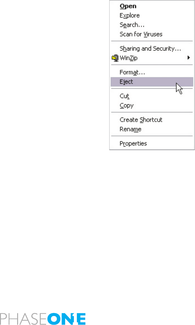
60
6.2 Mounting and dismounting card on computers
On Windows XP and Windows 2000 you can avoid confusing the
system or, worst case, end up with a CF-card that was unintentionally
erased, it is required to safely eject the card by right clicking the icon in
“My Computer” and select the “Eject” option.
On a Mac the card have to be unmounted, by dragging it into the trash,
or selecting eject in the “File” menu, or ejecting from the Capture panel
inside the Capture One software.
Just removing it, and reinserting it can confuse the system, possibly
resulting in uncontrolled read or write errors. If this happens, restarting
the computer usually solves the problems.
Preparing the CF-cards
Most CF cards are pre-formatted and ready to be used in the P+ back.
The P+ back supports cards formatted in either FAT 16 or FAT 32.
If your card is not recognized in the P+ back it is possibly due to a
wrong le system formatting on the card.
Mac HFS, UNIX or NTFS le systems are not supported by the P+ back,
and cards with these le systems will not be recognized.
The card will have to be formatted in either FAT 16 or FAT 32 using a
computer, Mac OS X or Windows.
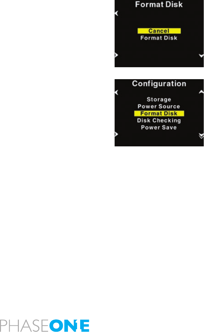
61
Recommended formatting is by using the back
Selecting “Format disk” will erase the CF-card in the P+ back. The CF-
card will be formatted as FAT-32.
Formatting on a Mac OS X computer
On Mac OS X the formatting cannot be done directly in the nder but is easily
done inside the Disk Utility located in the Applications > Utilities folder.
Open the Disk utility and select the Disk (not just the partition, but the
entire disk).
Select the Erase panel as shown on next page, and select MS-DOS File
System. Give the disk a name and click on Erase to erase and format
the entire disk for use with the P+ back.
Choose “Options” in the formatting dialog to specify a complete and
thorough formatting of the media.
Formatting on a Windows computer
Insert the CF-card in the card reader, and select the drive when it
mounts in “My computer” or in the Explorer.
Right click on the drive and select “Format” from the pop-up menu.
Select FAT32 or FAT16 from the “File System” pop-up.
Give the card a name and click Start to format the card to be used with
the P+ back.
To specify a complete and thorough formatting of the media resetting
all to zeros, do not enable the quick erase option.
Disabling iPhoto Autostart (Mac OS X)
iPhoto Autostart can be disabled in the Mac system preference.
Select “CD’s & DVD’s” and change the setting for “Picture CD” to either
“Ignore” or point it to the Capture One Application you are using.
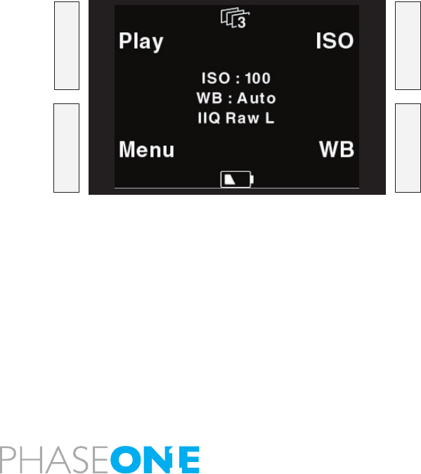
62
6.3 Navigating the Back menu
When the P+ back is turned on, the screen will always be in its home
display position or “Main screen”.
Pressing and holding down the upper left button on the back will also
bring you to the Main screen, regardless of where you are in the menu
system.
The Main screen has an indicator in the top showing remaining captures,
and a battery indicator at the bottom showing the remaining battery
capacity.
When either indicator reaches zero, it will start blinking, to indicate that
either storage or battery needs replacement before capturing any more
images.
The main screen also shows the current ISO setting, white balance
setting and IIQ Raw le format selected.
Menu buttons
The Phase One P+ back has four menu buttons to control the menu
system on the display.
When the P+ back is in its initial state (just after power up) or at the
menu systems “home” position (Main screen), the four buttons each
has a shortcut assigned. Play, Menu, ISO and WB.
Inside the menu system arrows will indicate the function of the four
buttons, the two buttons to the left are used to enter and exit the
selected menus. The two buttons to the right are used to go up and
down in the menu system.
•
•
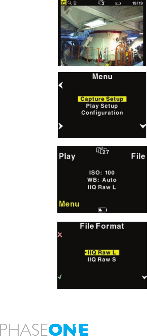
63
From the home position, pressing the “Play” button will bring up the
image browser, where you can go up and down with the right hand
buttons, to browse through images.
Pressing the “Menu”” button will bring you to the menu system where
you can scroll up and down in the menu system with the right hand
buttons to select the menu options to set.
When the desired option is highlighted it can be selected by pressing
the “Enter” button.
Exiting the menus is done with the “Exit” button.
Home shortcut
Holding down the “Exit” button for a few seconds will always bring you
to the home position or main screen immediately.
File format shortcut
Holding down the “Menu” button while in Home position colors the
word “Menu” in yellow, and at the same time reveals a shortcut with the
word “File” in the place where ISO was.
Pressing this button at the same time will bring up the File format Menu,
where you can select between IIQ Raw L and IIQ Raw S. For more
explanation on selecting in the menus please consult the “Menu mode”
section later in this manual.
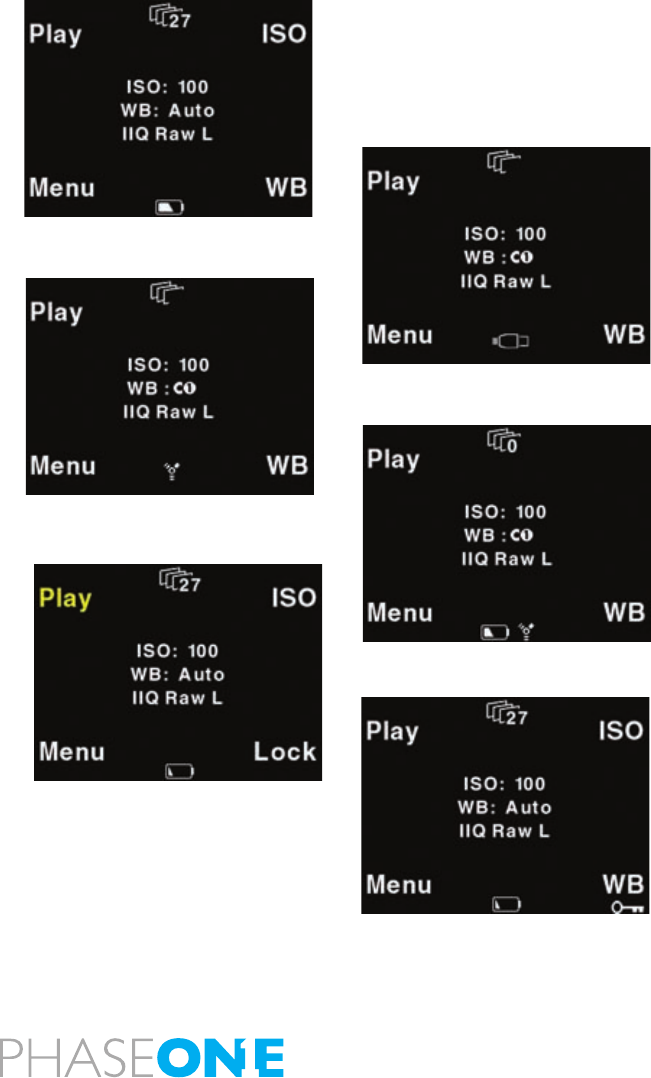
64
Battery and Power Indicator
The below screen dumps illustrates the battery and power mode
indicators.
This is the initial view that meets the user when switching on the P+
back (not connected to a computer)
When a FireWire cable is inserted and the P+ Back draws the power from
FireWire this is shown with an icon in the bottom of the main menu.
When Capture One is started on the computer this is indicated with a
FireWire Icon in place of the cable icon.
When the P+ back is forced to get power from the battery, this is
indicated with an additional battery icon.
Force battery power is invoked from the “Conguration > Power Source” menu.
Button Lock shortcut
Holding down the “Play” button while in Home position colors the word
“Play” in yellow, and at the same time reveals a shortcut with the word
“Lock” in the place where WB was.
Pressing this button twice when holding down the “Play” will lock
operation of the four menu buttons. This is useful to avoid unintended
button operation while carrying around the camera.
To Unlock the buttons hold down the “Play” button again and tab the
“Lock” button twice again. When the buttons are locked, the key icon
is displayed just below “WB”.

65
6.4 Playmode
“Play mode” can be used to review, zoom and delete images.
From the “Main screen”, pressing the top left button the P+ back is set
to Play mode.
In Play mode the top of the screen will show a menu bar. In the right
side of the menu bar the current image number and the number of
images captured on the media is displayed. In this example it shows
number 5 out of 19 images.
Pressing the Up and Down buttons on the P+ back (right hand side) it
is possible to browse through the images.
Holding down the “Enter” button while pressing the up and down icon
will bring you to the rst and last image accordingly.
Battery life and number of captures left are also shown in the menu
bar.
Pressing the Play button on the P+ back (top left hand button) will step
through the options available in the menu bar.
From left to right these are: Review, Zoom and Delete.
Pressing the “Enter” button on the P+ back (bottom left hand button)
selects the option.
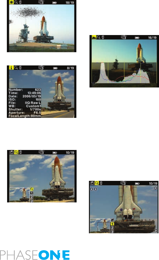
66
View modes
Play mode has four view modes, or review modes; Normal image display,
Exposure warning overlay, Histogram overlay or File Info overlay.
After entering the Play mode, press the “Enter” button to shift to the
view mode you want.
Exposure warning overlay will knock out the highlight areas as a ashing
color, to warn about burned out areas in the image.
Histogram overlay will show a transparent Histogram over the image.
File Info overlay will show detailed capture information like capture
number, capture time, date, ISO, WB, le format and shutter speed, etc.
The setting that Play mode is left in will also be the setting used for
review of images while shooting.
This means, that if the Play mode is set to show images with a histogram,
and you then exit to the Main screen. All subsequent captures will be
shown on the display with a histogram over the image.
6.5 Playmode – zoom functions
After entering Play mode, advance to the eyeglass icon by pressing the
Play button again and press the “Enter” button to select it.
It is now possible to zoom in the image with the “Enter” button.
The zoom has four amounts, Normal, enlargement 1, enlargement 2
and enlargement 3.
When zoomed into enlargement 1, 2 or 3 the insert view in the lower left
corner can be used to navigate around in the image.
A small rectangle will show the current position and the up and down
buttons can be used to scroll up and down.
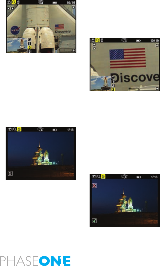
67
An icon just beside the Play button (top left hand button) will show the
direction of scroll as either vertical or horizontal.
Pressing the “Play” button once will change this from horizontal to
vertical scroll when using the up and down buttons. (Left side)
To exit the zoom function use the enter key to navigate to the eyeglass
icon in the pan view and press the Play button to step to the next icon in
the menu bar. Or hold down the “Exit” button for more than 1 second.
Browsing inside Zoom
While in the Zoom tool (enlargement 1, 2 or 3) holding down the “Enter”
key, will hide the two up and down indicators. It is now possible to
browse through the images by pressing the Up and Down buttons
without leaving the Zoom functions.
This means that the exact same focus point can be evaluated on several
pictures in a row by pressing “Enter” - “Up” or “Enter” - “Down”.
Delete
Navigate to the delete function by pressing the play button.
When in the delete view press the Up and Down buttons to browse
through images.
Pressing the Enter button brings up an X or a √ (checkmark). Pressing
“Enter” again will select √ and delete the image.
Pressing the exit button will select X and cancel the deletion.
If “Conrm Delete “ is set to “Off” in the “Play Setup”, the X and √
conrmation will be skipped, and the image deleted immediately when
pressing “Enter” while on the delete menu.
Exit the Play mode
Exit the Play Setup at any time by holding down the Play button for two
seconds.
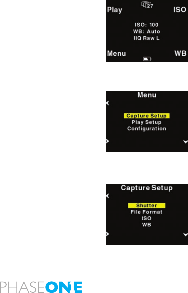
68
6.6 Menu Mode
Pressing the lower left button sets the P+ back in “Menu mode”
Entering Menu mode by pressing the lower left button allows you to set
up all the preferences of the P+ back.
Menus are navigated by following the Enter, Exit, Up and Down arrows
and pressing the corresponding buttons on the P+ back.
Whenever you want to exit to the main screen hold down the exit button
(upper left button) for more than two seconds, and you will be back at
the main screen.
When entering the menu mode you have three options: Capture Setup,
Play Setup and Conguration.
Capture Setup
Capture Setup is where you setup preferences for the capture.
Enter the Capture Setup by pressing the enter button (lower left button)
In the Capture Setup you can select ISO, WB, FileFormat or Shutter.
By scrolling down with the down button you can select the options.
Shutter
Shutter refers to the shutter of the camera the P+ back resides on.
Due to the sleeping architecture of the P+ back, where the CCD is put
to sleep to reduce power consumption, the P+ back needs to wake up
before shooting. The timing of this wake up signal is referred to as the
latency.
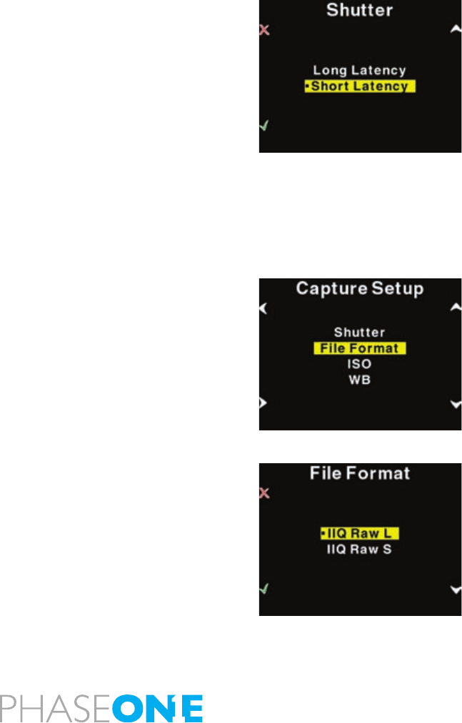
69
In general, if the camera is used with medium format cameras with
digital interface the setting can be either “Short latency” or “Long
latency”.
Short latency has a shorter response time, but is power consuming, so
when battery time is an issue you should select “Long latency” on the
cost of response time from the camera.
If the P+ back is used in “two shoot mode” on a large format camera
with i.e. a copal shutter or another mechanical shutter where the
shutter is released one time for waking up the back, and another time
for shooting the image, then the shutter setting in the P+ back should
be set to “long latency”.
While short latency will respond immediately to triggering the camera,
Long latency will not be that fast, but in return you gain much longer
battery power.
FileFormat
In “FileFormat” you can select two options “IIQ Raw L” and “IIQ Raw S”.
“IIQ Raw” is a short term for Intelligent Image Quality Raw.
“IIQ Raw L” is set as the default and is the loss less capture format of
the P+ back.
“IIQ Raw S” is a smaller le, and not totally loss less in the format. The
“IIQ Raw L” is approximately 1/3 le size of the processed TIFF le.
“IIQ Raw S” is approximately 1/5 of the processed TIFF. Most users will
use the “IIQ Raw S” as there is virtually no quality difference between
the two settings.
Please consult the camera specic sections in this manual to learn
more about how to use shutter latency with your particular P+ back
setup.
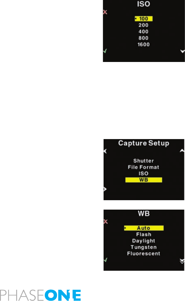
70
ISO
In the ISO Menu choose from ISO 50 to ISO 1600 depending on the
conditions you want (number of ISO options may vary depending on
which model P+ back is used).
In general the higher ISO, the more noise in the image. This means that
for optimal image quality, it is a better strategy to have more light in
the scene, or adjusting the f-stop on the camera, than just turning to a
higher ISO.
When the preferred ISO setting is set press the “Enter” button to conrm
the choice (green √ check mark).
Or if you regret the choice and just want to go back to the previous
setting (the one with the little dot), select the “Exit” button (the red X).
White Balance
Setting Auto WB will calculate a white balance based on the information
in the image. Auto WB is good for most applications.
If you are using a specic lightsource you can choose that option here.
If the camera back is tethered to a computer, and white balance is set
from within Capture One it is indicated with the C1 icon in place of the
WB indicator on the main screen.
Custom White Balance
Your P+ back allows you to create up to 3 custom white balances.
Custom WB is available when pressing the WB button at the main
menu.
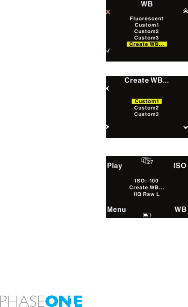
71
When scrolling to the bottom of the WB options four options are
available:
“Custom1”, “Custom2”, “Custom3” and “CreateWB…”
To make a new custom white balance select CreateWB… and choose
which one from the following: “Custom1”, “Custom2” or “Custom3”
When one of the options is selected the “Make Custom WB” will be blinking.
Now you are ready to capture the image that should be used for white
balancing. Place the viewnder center circle on an area (gray card or neutral
white surface) and capture the image. You have now made the custom white
balance and it has been set as the current capture white balance.
All subsequent captures will now have the new custom white balance
applied.
3 different custom white balances can be dened and used as shooting
white balances.
Custom white balance from Capture One
You can also choose to easily transfer a white balance from Capture
One to the P+ back:
1. Create a custom white balance inside Capture One.
2. While tethered to the computer select WB from the lower right button
on the P+ back.
3. Select “Custom1”, “Custom2” or “Custom3” on the P+ back
depending on where you want to store the new white balance.
4. Finally Click the “Set as capture white balance” button inside capture
One.
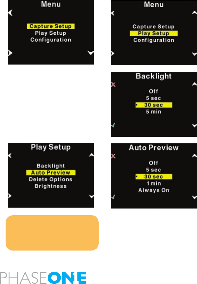
72
The P+ back will beep, conrming that the custom white balance is now
uploaded, will be applied when the P+ back has been disconnected.
This technique is useful because you can bring up to three predened
custom white balances taken in the studio to your location shoot.
Please be aware that when shooting tethered to the computer, the white
balance must still be set in the Capture One application. White balance
cannot be set on the P+ back while tethered.
Play Setup
The second option in the menu mode is Play Setup.
Inside “Play Setup” you can select between “Backlight”, “Auto Preview”,
“Delete options” and “Brightness”.
Backlight
“Backlight” allow you to setup how many seconds or minutes of
inactivity there may be before the light of the display fades.
This setting affects the battery life of the P+ back. The more time before
light is dimmed, the faster the battery is drained.
Auto Preview
The second option in “Play Setup” is “Auto Preview”. “Auto Preview”
refers to the time the image is remains on the screen after capture.
If Auto Preview is set to “Off” the preview will not be shown automatically
when a capture is taken.
Notice
- If a button is touched during the
auto preview period, the preview will
remain on and the time-out will be
disabled until next capture.
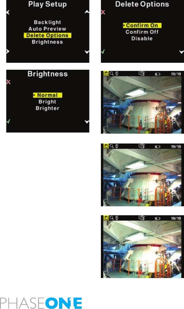
73
Delete options
There are three delete options: “Conrm On”, “Conrm Off” and
“Disable”.
In Delete options you can setup whether you want an extra conrmation
when you delete images (Conrm On - Default), delete images
immediately (Conrm Off), or you can disable deleting of images on the
P+ back to avoid unintended loss of images.
Brightness
In the Brighness setup, you can set the brightnes of the preview LCD
screen
Default setting is Bright.
Only the Brightness of the display is affected. Exposure warning,
histogram and nal capture is not affected by this setting.
When you are outdoor with much ambient light this is helpful but
especially with images taken with low-light, a brighter display is
helpful.
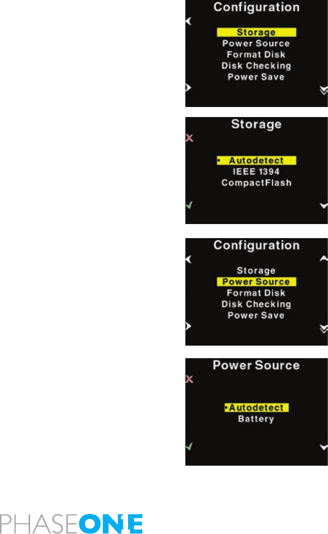
74
Configuration
“Conguration” is used to setup general settings and perform general
tasks on the P+ back.
“Conguration” contains more menu entries than can be displayed on
one screen. This is indicated by a double arrow pointing down on the
right side.
Scrolling past the last menu entry will reveal the next entry. Now the
arrow in the top right side will turn into a double arrow, to indicate that
there are hidden entries at the top.
Storage
“Storage” is as default set to “Autodetect”. If a card is inserted in the P+
back it will automatically capture to this card. If not, it will try to capture
via the IEEE 1394/FireWire port directly to the computer. – if a card is
in the back at the same time as the back is connected by FireWire to a
computer, this connection will have priority.
If the P+ back is not tethered to a computer you will get an error message
that the card slot in the P+ back is empty.
The P+ back can also be forced to shoot to either Compact Flash or
IEEE 1394/FireWire by selecting the options inside “Storage”.
Power Source
Power source only has two options, “Autodetect” or “Battery”.
In Autodetect, the P+ back will detect if an IEEE 1394/FireWire connection
is supplying power, and automatically shut of the battery power.
If Power Source is set to “Battery” the power source is forced to come
from the battery, and the digital back will not consume power from the
FireWire connection.
This is especially useful to avoid draining the battery in a MacBook or
PowerBook.
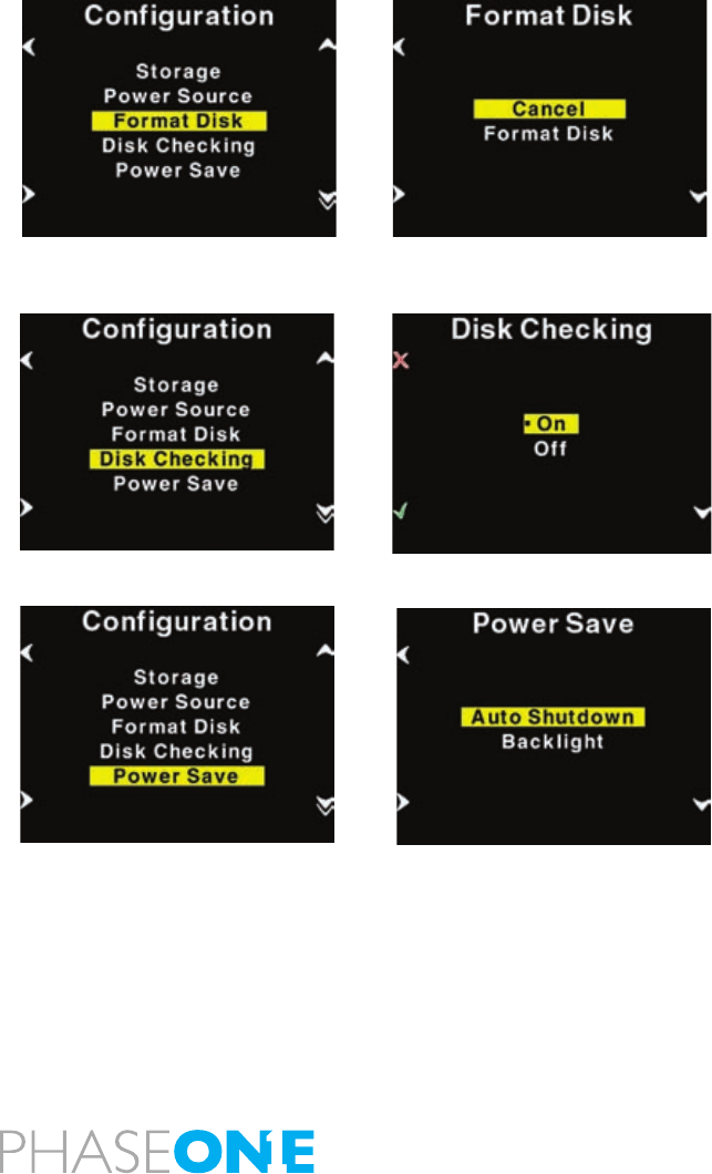
75
Format disk
Selecting “Format disk” will erase the CF-card in the P+ back. The CF-
card will be formatted as FAT-32.
Please see CF-card section for troubleshooting if your card is not
recognized.
Disk Checking
Disk Checking is done per default on every card inserted to the P+ back.
If for some reason this check is not wanted the feature can be turned
off in this menu.
Phase One recommends leaving diskchecking turned on, to maximize
data security on memory cards.
Read more about the Phase One Secure Storage system in Chapter 5
of this manual.
Power Save
Power Save only has two options “Auto Shutdown” and “Backlight”.
Auto Shutdown is used to set the time frame before the P+ back Shuts
down, when there Is no activity.
If the P+ back is automatically shut down it can only be woken up by
pressing the “Power” button.
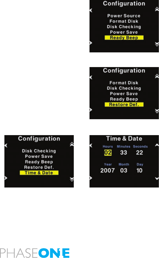
76
Ready beep
“Ready beep” is the small beep that sounds from the back when ready
for a new capture.
The “Ready beep” signals that the P+ back is ready for next capture.
“Ready beep” can be either “Single”, “Multi” or “Off”. Default is
“Single”
“Multi” is for use in noisy surroundings, i.e. where it can be difcult to
hear if it was the back or the ash that made the ready beep.
Restore def. (Defaults)
Selecting restore defaults will restore the settings of the P+ back to its
default settings. Be careful before using this option as all settings made
in the P+ back will be reset to factory settings.
Time & Date
In “Time & Date” you can set the time and date using the four buttons
on the P+ back. Left side buttons will step through the hours, minutes
and seconds eld, while the right up and down buttons can be used
to set the value of the elds. The time and date is applied to all les
captured with the P+ back.
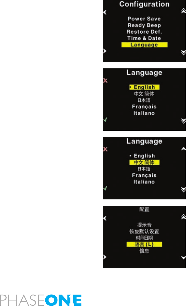
77
Language
The “Language” option in the “Conguration” Menu can be used to
select preferred language of the user interface.
Expressions in the main menu like: ISO, WB, Play and Menu are not
translated.
These are regarded as icons, and also understood widely as expressions
used to navigate even on the Japanese or Chinese interface.
However switching to an unknown language unintentionally can be
frustrating and the user can have difculty getting it back to the native
language back on the menu.
Phase One have made this easy by incorporating a large “L” in a
parenthesis after the Language menu.
Finding this “L” will help the user get the native language back.
Currently (When this manual was written) the following languages are
supported on the P+: English (default), Japanese, Chinese (Simplied),
French, Italian, German and Spanish.
If there is sufcient request for more languages, these might be made
available through a Firmware upgrade.
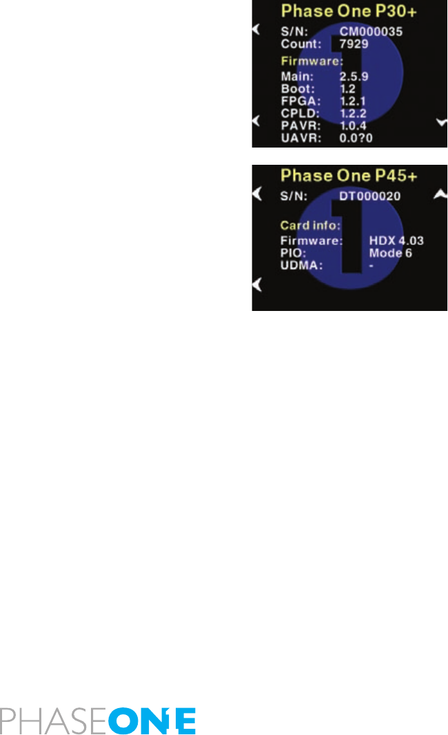
78
About the P+ Back
The “About” option in the “Setup Menu” displays technical information
about the hardware and embedded software (“Firmware”) in the camera.
This is especially
useful if support is needed or if you want to check if Phase One is
offering a newer rmware for your camera.
Firmware might be made available in the download section at
www.phaseone.com
Before contacting your dealer or Phase One Support please make sure
to have access to the “About “box or write down the entire contents of
the “About” box.

79
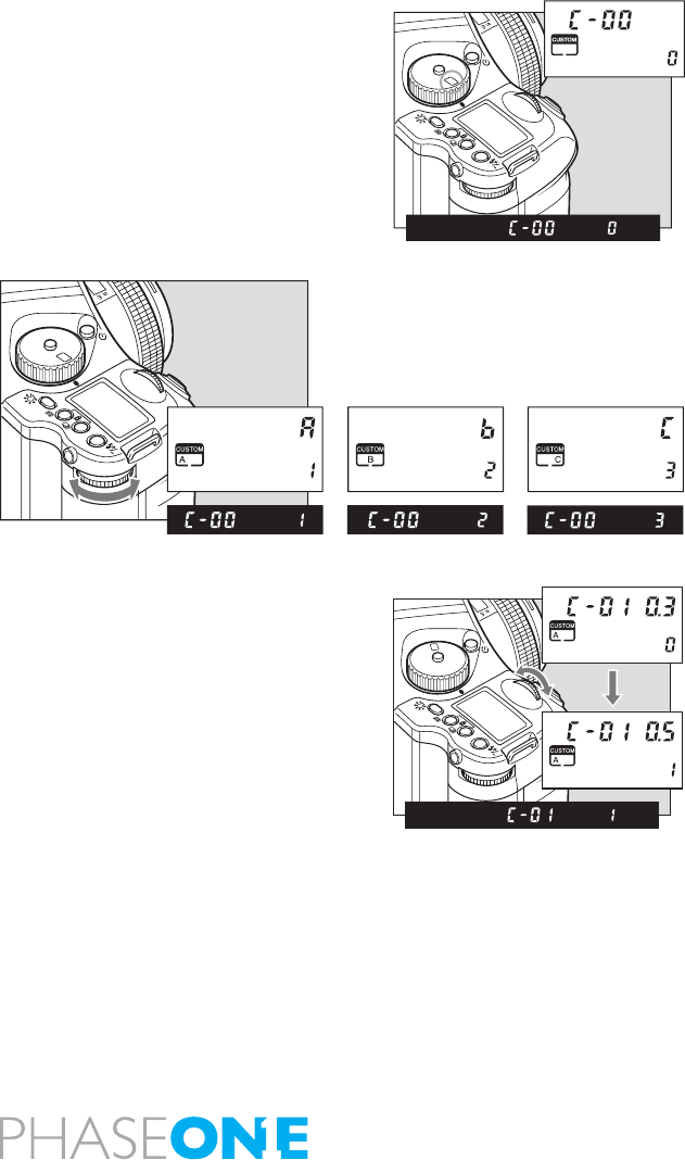
80
7.0 Custom function
The functions of Phase One 645 AF is predetermined to work in
one way, but you can personalize your camera platform to work the
way you prefer. No matter what you do in changes of the platforms
workingspace, you can always return to default, read more on this in
chapter 7.2 types of custom functions.
7.1 Setting custom functions
The custom functions allow you to change the method for using or
accessing the camera functions as you like. Take photographs the way
you are most comfortable with.
The custom functions can store separate settings for 3 users. You can
preset the functions for indoor, outdoor or portrait photographs and for
other conditions. When at C-00, chose 1 (A), 2 (B), or 3 (C) to store a
specic set of user function selections for the group of custom settings
from C-01 to C-32.
However, if you set C-00 to 0, the settings used will be the default set.
With this choice you can change only C-31 to 35.
X
M
Tv
Av
P
CF
SET
AEL
X
M
Tv
Av
P
CF
SET
AEL
SET
AEL
P
Av
Tv
M
X
CF

81
7.2 Types of custom functions
C-00 Custom functions No.
0: [Initial setting]
1: A
2: B
3: C
When “0” has been selected and set, none of the custom items can
be set. “1,” “2” or “3” must be selected and set without fail.
C-01 Steps of aperture, shutter speed, exposure compensation.
This function is used to set the shutter speed, f-number and exposure
compensation value step width.
0: 0.3 (1/3EV step: initial setting)
1: 0.5 (1/2EV step)
2: 1.0 (1EV step)
C-02 Data imprinting
This function is used to set whether to imprint the shooting data on
the lm.
0: No imprinting (initial setting)
1: Yes (data, index)
2: Yes (date, index)
C-03 Aperture setting after lens change
This function is used to set the f-number display method for the
previously used lens when the lenses have been changed over. The
initial setting is “Yes,” in which case the f-number of the lens prior to
the changeover is displayed.
0: Yes (previous f-number: initial setting)
1: Aperture open
2: Minimum aperture setting
3: Number of stops from open
C-04 Metered value display time
This function is used to set the time it should take for sleep mode to be
established after the camera’s power is turned on. The initial setting is 15
seconds.5, 10, 15, 20, 25, 30, 40, 50, 60 or “on” can be selected and set.
Note that the batteries will discharge when “on” (no sleep mode) has
been set.
C-05 Range of exposure compensation
This function is used to set the maximum extent of exposure
compensation. Its setting takes effect in AE shooting modes (P, Tv and
Av).
0: ±3EV (initial setting)
1: ±5EV
C-06 External LCD backlight
This function is used to set the method for lighting the backlight of the
external LCD panel.
0: Set using Backlight button (initial setting)
1: Always on (metering retention period)
C-07 Select battery
This function is used to set the batteries used in the camera so that
the remaining battery charge will be displayed correctly on the external
LCD panel.
0: Primary batteries (alkaline/manganese batteries, lithium batteries:
initial setting)
1: Secondary batteries (nickel-metal hydride batteries, nickel-cadmium
batteries)
C-08 Bracketing order
This function is used to set the shooting sequence for auto bracketing.
The initial setting is “n-u-o” (normal/under/over). The shooting sequence
for 2-frame bracketing is set in auto bracketing setting mode.
0: n-u-o (normal/under/over: initial setting)
1: n-o-u (normal/over/under)
2: u-n-o (under/normal/over)
3: o-n-u (over/normal/under)

82
C-09 Cancel auto bracket
This function is used to set the release method of the auto bracketing
shooting setting upon completion of auto bracketing shooting.
0: Released by turning the power OFF (initial setting)
1: Until released
2: Released after one shot
C-10 Manual mode bracketing
This function is used to set whether bracketing is to be performed
using the shutter speed or f-number during M (manual) mode auto
bracketing shooting.
0: Shutter speed (initial setting)
1: F-number
C-11 Front/Rear dial function exchange in manual mode
This function is used to change over the operations of the front and
rear dials in the M (manual mode).
0: Front dial: shutter speed, rear dial: f-number (initial setting)
1: Front dial: f-number, rear dial: shutter speed
C-12 Rear function dial enabled/disabled
In the initial setting, exposure compensation can be provided by the
sub (rear) dial in P, Tv and Av modes. This function is used to set
whether to allocate the operations of the front dial to the rear dial.
0: No (exposure compensation: initial setting)
1: Yes
C-13 Dial function direction
This function is used to determine the direction in which the electronic
dial is to be rotated to increase and decrease shutter speed, the f-
number, and exposure compensation.
0: No switching (CCW: decrease,
CW: increase: initial setting)
1: Switched (CCW: increase, CW: decrease)
C-14 Program shift
This function is used to set the type of program shift. Under the initial
setting, the shifting is performed along the program line. Av enables
aperture priority shift within the possible metering range; Tv enables
shutter speed-priority shift.
0: Program shift (initial setting)
1: F-number shift
2: Shutter speed shift
C-15 AEL & AFL function button exchange
This function is used to set whether to change over the functions of the
front and rear AEL and AFL buttons.
0: No (front: AFL, rear: AEL: initial setting)
1: Yes (front AEL, rear: AFL)
C-16 Half-press shutter release function mode
This function is used to set the AE lock and AF operations when the
shutter button is half-pressed.
0: AF operation (initial setting)
1: AF operation/AE lock
C-17 AEL function lock/unlock mode
This function is used to set the method of operating the AEL button
to lock AE. At the initial setting, when the AEL button is pressed, AE
is locked; pressing the button again releases the AE lock. At the “1”
setting (released after one shot), after AE lock is set, it is released when
the shutter is tripped. At the “2” setting, AE lock is set while the shutter
button is being pressed.
0: Continuous: initial setting
1: Released after one shot
2: While the shutter button is pressed
C-18 Focus indicator selection
This function is used to set whether the defocusing mark is to be
displayed.
0: Yes (initial setting)
1: No (focusing mark only)

83
C-19 AFL function lock mode
This function is used to set the AF lock method when the AFL button
is operated.
There is a choice between AF locking by pressing the AFL button and
performing the AF operation for AF locking and AE locking.
0: Yes (AF lock only: initial setting)
1: Yes (AF operation/AE lock)
C-20 M mode one-push setting
This function is used to set whether one-push shift operation in manual
mode is to be based on the shutter speed or f-number.
0: Shutter speed shift (initial setting)
1: F-number shift
C-21 Bulb exposure time setting
This function enables bulb shooting by setting the bulb shooting time
from 1 to 60 minutes provided that the battery charge lasts. It can be
used to decide on the bulb shooting time from 1 to 60 minutes.
C-22 Bulb shutter release setting
This function is used to set how to operate the shutter button for bulb
shooting. At the “0” setting, the shutter is opened and closed while
the shutter button is held down; at the “1” setting, it is opened and
closed each time the shutter button is pressed.
0: While shutter button is pressed (initial setting)
1: Each time shutter button is pressed
C-23 Shutter speed in X mode
This function is used to set the shutter speed in X (synchronizing)
mode. The initial setting is 1/125 sec. The kind of large ash unit for
use in studios has a long ring time and so it may not synchronize at
a high shutter speed setting. Take one or more test shots, and set the
synchronization speed.
0: 1/125 sec. (initial setting)
1: 1/90 sec. (1/80 sec.*)
2: 1/60 sec.
3: 1/45 (1/40 sec.*)
* When the exposure value step width has been set to 1/2 step
C-24 Automatic sync speed setting
This function is used to set the shutter speed when using the ash unit
made by Metz (with the SCA3952 adapter) in P (program) or Av mode.
0: 1/60 to 1/125 sec. (initial setting)
1: Less than 1/125 sec. (metered value)
C-25 TTL flash compensation mode
This function is used to set whether to link exposure compensation and
ash compensation when using the ash unit made by Metz (with the
SCA3952 adapter).
0: Not linked (initial setting)
1: Linked
C-26 AF beam setting
The AF auxiliary light res automatically when the subject is too dark
to perform AF, but this function can be used to prevent the AF auxiliary
light from ring.
0: Fires (initial setting)
1: Does not re

84
C-27 Flash sync. timing
When a moving subject has been shot using the ash, a ash of light
will appear ahead of the subject’s movement under the initial setting.
This function makes it possible to change this so that the ash of light
comes after the moving subject as illustrated.
0: No (front curtain synchronization: initial setting)
1: Yes (rear curtain synchronization)
C-28 Copy custom function
This function is used to group all the user symbol settings selected
(custom functions that have been set) together with the other user
symbols, and copy them.
0: No (initial setting)
1: Yes (copied to user A)
2: Yes (copied to user B)
3: Yes (copied to user C)
C-29 Custom function reset
This function is used to group all the user function settings selected
from C-01 to C-27 together, and initialize them (to the default
settings).
0: No (initial setting)
1: Yes
C-30 Shutter release without film
This function is used to set whether the shutter is to be tripped even
when the lm has not been loaded.
0: No (initial setting)
1: Yes
C-31 Auto film loading setting
This function is used to set whether to feed the lm (to the rst frame)
by halfpressing the shutter button or by closing the rear cover when
the lm has been loaded. The lm can be fed to the rst frame by
halfpressing the shutter button even when the rear cover close has
been established as the setting.
0: By half-pressing the shutter button (initial setting)
1: By closing the rear cover
When the camera is in sleep mode, the lm will not start moving even
when the rear cover is closed. Half-press the shutter button.
C-32 Multiple exposure mode
This function is used to select whether, during multiple exposure
shooting, the multiple exposures are to be taken by pressing the shutter
button until the multiple exposure button is pressed after the number
of multiple exposures has been set (initial setting). When the number of
multiple exposures is set, the lm is wound up by one frame after the
completion of the number of multiple exposures.
0: Until the multiple exposure button is pressed (initial setting)
1: Multiple exposure number is set
C-33 Digital back CF configuration
This function is used to select the user function (A, B or C) when an
MSCElisted digital pack has been loaded.
0: No (initial setting)
1: A
2: B
3: C
C-34 Clock/calendar setting
This function is used for setting the calendar and clock.
C-35 Index setting
This function is used for setting the index numbers. – ONLY relevant
when using lmback.
C-36 firmware version -
Press+/- to view rmware version: number on top of display is body
rmware. Number on bottom of display is rmware number for the
mounted lens.

85
Custom Functions overview
No. Item Initial setting (0) 1 2 3
C-00 Custom Function User standard User A User B User C
C-01 Steps of aperture, shutter speed,
Exposure compensation
1/3 EV step 1/2EV step 1 EV step
C-02 Data imprint No Data, Index Index, Date
C-03 Aperture setting after lens change Previous aperture value Open Minimum
C-04 Metered value display time 15 sec. 1:20 2:25 3:30 4:40 5:50 6:60 7:ON 8:5 9:10
C-05 Range of exposure compensation ± 3EV ± 5EV
C-06 External LCD backlight set using backlightbutton
C-07 Battery type Alkaline/manganese
(standard batteries)
Ni-CD, Ni-MH
C-08 Bracketing order Normal-Under-Over N-O-U U-N-O O-N-U
C-09 How to cancel Bracketing Power OFF Push bracketing button Release after one session
C-10 Bracketing variable Shutter speed Aperture value
C-11 Front/Rear dial function exchange in
manual mode
Front:Tv
Rear :Av
Front:Av
Rear :Tv
C-12 Rear function dial enabled/disabled in P,
Av, Tv
Enabled Disabled
C-13 Dial function direction Right: decrease
Left: increase
Right: increase
Left: decrease
C-14 Program PH/PL PHigh/PLow Av Shift Tv Shift
C-15 AEL & AFL function button exchange Front: AFL
Rear : AEL
Front: AEL
Rear : AFL
C-16 Shutter half-press function AF operation AF operation &
AE Lock
C-17 AEL function lock/unlock mode Until turned off Released after one shot While the shutter button
is pressed
C-18 Focus Assist On Off
C-19 AFL function lock mode No AF operation before
locking
AF operation before
locking
1st push Lock
2nd push unlock
C-20 M-mode in one push setting Shutter speed shift Aperture value shift
C-21 Bulb exposure time setting 60 minutes 1:Off 2:1 3:2 4:4 5:8 6:15 7:30
C-22 Bulb shutter release setting While shutter button is
pressed
start/stop exposure
when shutter is pressed
C-23 Shutter Speed in X mode 1/125 1/90(1/80) 1/60 1/45
C-24 Automatic sync speed 1/60 to 1/125 metered value
(less than 1/125)
C-25 TTL ash compensation mode On Off
C-26 AF beam setting On Off
C-27 Flash sync. timing 1st Curtain 2nd Curtain
C-28 Copy custom function No copy Copy to A Copy to B Copy to C
C-29 Custom function Keep settings Reset settings
C-30 Shutter release without lm No Yes
C-31 Auto lm loading setting Shutter button half-pressed Closing rear cover
C-32 Multiple exposure mode stop Until multiple exposure
button is pressed
multiple exposure
number setting
C-33 Custom function preference Standard settings User A User B User C
C-34 Clock/Calendar setting
C-35 Index setting
C-36 Firmware version Press EV+/-, the top number is body rmware the below number is lensrmare
Only relevant when using lmback
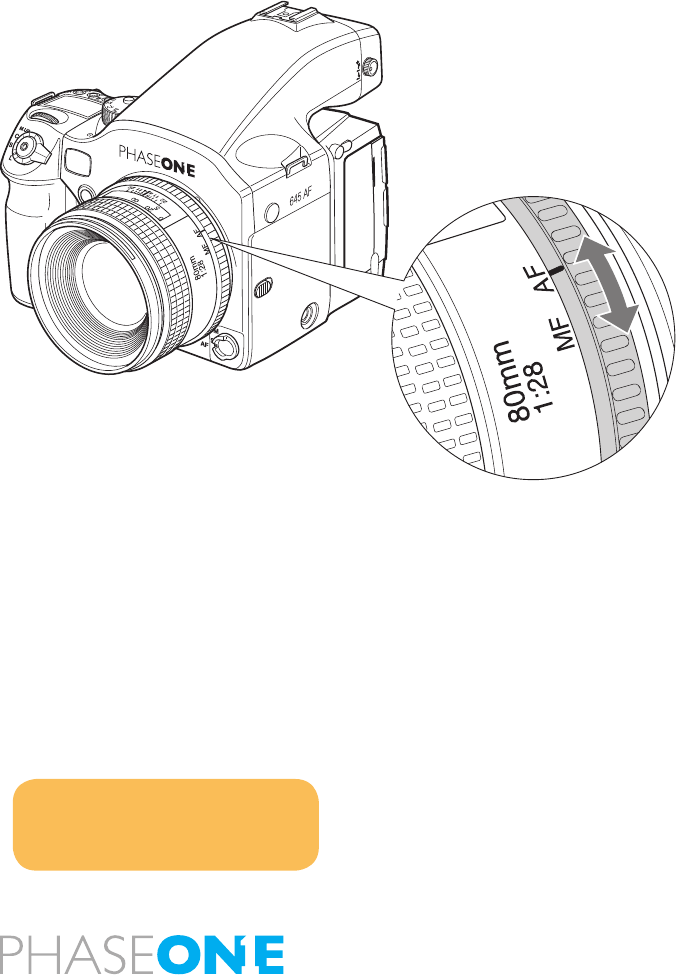
86
8.0 Lenses and Multi Mount
Phase One provides the widest range of possibilities, when it comes
to lenses, this increases the possible creative solutions for the
photographer, This chapter is looking closer at some possible lenses,
but it is worth noticing that there are more lenses usable than what we
show here. The enthusiastic user can nd loads of information on the
internet as well as mount-adaptors, like the Phase One Multi-Mount.
Phase One will of course always recommend our products, but we are
well aware that creativity will only grow co-operation and by using the
free market and free choices that follows the market.
Please note, errors or damage caused by thirds party products is not
covered by the warranty, test new product with curious caution.
8.1 Functions of the Phase One lens
The Phase One 80mm f.2,8 - a sharp, new and well tested digital
photography prepared lens. The lens is mounted by aligning the white
dot on the lens right in front of the white dot on the camerabody,
carefully mount the lens by turning it clockwise, until a clicksound is
heard, if you feel resistance or if you hear a grate-like sound stop and
retry – NEVER use force when mounting the lens, it should always slide
in without resistance.
The lens has 2 rings, the inner ring provides the possibility of changing
the focus mode without changing grip of the body, keep the focus
selector on the camera body on either “S” or “C” to decide whether
focusing single or continuously, and decide whether to do autofocus or
manual focus on the inner ring of the lens.
The focus ring is the outer ring on the lens, use this ring to manually
set the focus, read more on focusing in the chapter 3.4 regarding
autofocus.
Notice:
If you select MF on the camera body,
you might have to turn the camera off
before the autofocus will start.

87
8.2 Function of the Phase One lens adaptor
To mount the Phase One Multi-Mount, match the white dot on the
camera up with the white dot on the Multi-Mount and turn slowly
clockwise, NEVER use force to mount the ring. When the Phase
One Multi-Mount is mounted you can t Carl Zeiss/Hasselblad V and
Hasselblad 200series lenses on the camera.

88
8.3 List of alternative lenses
Recommended digital lenses
Producer specs limitations adaptor/mount notice
Mamiya 28 f.4,5 AFD Mamiya 645AFD Sekor
Mamiya 75-150 f.4,5 Mamiya 645AFD Sekor
Recommended lenses
Mamiya 35 f.3,5 Mamiya 645AFD
Mamiya 45 f.2,8 Mamiya 645AFD
Mamiya 55 f.2,8 Mamiya 645AFD
Mamiya 150 f.3,5 Mamiya 645AFD
Mamiya 210 f.4,0 Mamiya 645AFD ULD
Mamiya 300 f.4,5 Mamiya 645AFD APO
Mamiya 55-110 f.4,5 Mamiya 645AFD
Mamiya 105-210 f.4,5 Mamiya 645AFD ULD
Producer specs limitations adaptor/mount notice
Recommended MF lenses
Mamiya A 500 f.4,5 1+2 Mamiya 645 MF
Mamiya A 300 f.2,8 1+2 Mamiya 645 MF+APO
Mamiya A 200 f.2,8 1+2 Mamiya 645 MF+APO
Mamiya 55 1+2 Mamiya 645 leafshutter
Mamiya 80 f.2,8 N/L 1+2 Mamiya 645 leafshutter
Mamiya 150 f.3,8 N/L 1+2 Mamiya 645 leafshutter
Mamiya 105-210 f.4,5 1+2 Mamiya 645
Mamiya 500 f.5,6 1+2 Mamiya 645
Mamiya 55-110 f.4,5 N 1+2 Mamiya 645
Mamiya 150 f.2,8 1+2 Mamiya 645
Mamiya 300 1+2 Mamiya 645
Mamiya 24 f.4,0 1+2 Mamiya 645
Mamiya 35 1+2 Mamiya 645
Mamiya 150 f.3,5 N 1+2 Mamiya 645
Mamiya 45 1+2 Mamiya 645
Mamiya 210 N 1+2 Mamiya 645
Mamiya 80 f.1,9 1+2 Mamiya 645
Mamiya 55 1+2 Mamiya 645
Mamiya 80 f. 2,8 N 1+2 Mamiya 645
Hartblei MC TS-PC 45 f. 3,5 mamiya/Pentacon six super-rotator tilt/shift
Hartblei MC Hartblei 2x converter pentacon six
Producer specs limitations adaptor/mount notice
Arsat MC Arsat 30 f.3,5 sheye Pentacon six
Arsat MC Arsat 45 f.3,5 Wide Angle Pentacon six
Arsat MC PCS Arsat 45 f.3,5 Pentacon six shift
Arsat MC PCS Arsat 55 f.4,5 Pentacon six shift
Arsat MC PCS Arsat 65 f.3,5 Pentacon six shift
Arsat MC Arsat 80 f.2,8 Pentacon six
Arsat MC Arsat 600 f.8,0 Pentacon six Mirror
Lenses usable in combination with Phase One Multi-Mount
Carl Zeiss CFi 30 f.3,5 3 hasselblad V
Carl Zeiss CFE 40 f.4,0 3 hasselblad V
Carl Zeiss CFi 50 f.4,0 3 hasselblad V
Carl Zeiss CFi 60 f.3,5 3 hasselblad V
Carl Zeiss CFE 80 f.2,8 3 hasselblad V
Carl Zeiss CFi 100 f.3,5 3 hasselblad V
Carl Zeiss CFE 120 f. 4,0 3 hasselblad V
Carl Zeiss CFi 150 f.4,0 3 hasselblad V
Carl Zeiss CFE 180 f.4,0 3 hasselblad V
Carl Zeiss CFi 250 f.5,6 3 hasselblad V
Carl Zeiss CFE 350 f.5,6 3 hasselblad V SA
Special purpose lenses
Mamiya 120 f.4,0 MACRO Mamiya 645 MF
Mamiya 50 SHIFT 1 Mamiya 645 MF
Mamiya 645 Auto bellows unit 1 Mamiya 645
Mamiya 80 MACRO 1 Mamiya 645
Other lenses usable in combination with adapter
Hasselblad 30 sheye
Hasselblad 40
Hasselblad 50
Pentacon ektogon 50
Arsat 55mm Shift
Biometar 80mm
Biometer 120mm
Sonnar 180mm
Limitationcodes:
1: Stopped down metering not possible
2: Discontinued
3: Leaf shutter disables, only aperture priority

89
8.4 Lens Cast
What is Lens Cast?
Lens cast may occur if using the camera back with wide- angle lenses
e.g. Horseman Digiex II, Hasselblad Flexbody or Hasselblad 905SWC
or on other large format cameras with different tilt or swing settings.
On a medium format camera lens cast is very rare if using xed lenses
from 60 mm to 120 mm.
Why does lens cast occur?
Lens cast occurs as a result of the angle at which the CCD is exposed to
light. If the CCD is exposed to light coming from a very sharp angle e.g.
wide-angle or extreme degrees of tilting you may experience lens cast.
What does it look like?
Depending on the light conditions and photographic setup, lens cast
can appear differently, on some lens/back combinations there will
appear to be a transition from green-ish to magenta-ish, but blue, red
- all colors can appear, if you want to test your lens for color cast, take
a photo of a grey wall or cardboard. And check this image for colors.
How to get rid of Lens Cast?
If working with large format cameras with tilt and swing, you would
have to make a new calibration le if you change the tilt and swing
position. Phase One provides a solution in the Capture one software
that helps you get rid of the lens cast.
We call it: Lens Cast Calibration (LCC). By holding an opal white plate
in front of the lens and capturing a calibration image that you then
apply to all of your capture les you are able to remove the lens cast.
On medium format cameras the calibration is very simple: You do one
calibration for each lens and then save the calibration les and apply
them when needed by clicking “Set as default for new Captures”.

90
8.5 4 simple steps to calibrate on fixed lenses (MAC)
1. Hold the calibration plate in front of the xed lens (as close as
possible), and capture. In order to ensure correct exposure you may
have to up a few f-stops or in a very dark setup, put on more light
directly onto the plate.
2. In the Capture One software you select the ‘calibration’ image and
click on the “Save LCC” button (the LCC tool is located under the grey
balance tab).
3. Give the calibration le a name that corresponds to the lens in use or
the set-up (e.g. 45mmDaylight)
4. Select the calibration le: “45mm Daylight” from the “Lens CC” drop-
down list and click “Set as default for new Captures”.
8.6 Large format and stitched images (MAC)
Large format and stitched images (Mac)
When using LCC in combination with large format capture and image
stitching you must capture one calibration le per image and make sure
that you match the calibration le to the right image prior to stitching.
1. Start by capturing the two calibration les and the two image les.
2. Save the right-side calibration le by clicking the “Save LCC”
3. Name the calibration le i.e.CarsRight.
4. Save the left-side calibration le the same way.
5. Select the right-side image and apply the right-side calibration le.
Select the left-side image and apply the left-side calibration le.
6. A simple way to gray calibrate is to select all images in the thumbnail
window. Click on the left-side center of the right side calibration le and
apply that gray balance to all images by clicking the “Apply to all selected”
(remember to only select apply gray balance in the dialog).
PLEASE NOTE: As soon as grey
calibration is done and the calibration
files are saved and appear in the Lens CC
drop-down box the calibration files can
be deleted from the thumbnail window.

91
8.7 4 simple steps to calibrate on fixed lenses (PC)
1. Hold the calibration plate in front of the xed lens (as close as
possible), and capture. In order to ensure correct exposure you may
have to open up a few f-stops or in a very dark setup, put on more light
directly onto the plate.
2. In the Capture One software you select the ‘calibration’ image and
click on the “Generate…” button (the LCC tool is located under the
white balance tab).
3. Give the calibration le a name that corresponds to the lens in use or
the set-up (e.g. 45mmDaylight)
4. Select the calibration le: “45mm Daylight” from the “Lens CC” drop-
down list and set a checkmark in the “Apply LCC for next Captures”.
If working with large format cameras with tilt and swing, you would have
to make a new calibration le if you change the tilt and swing position.
When using LCC in combination with large format capture and image
stitching you must capture one calibration le per image and make sure
that you match the calibration le to the right image prior to stitching.

92
8.8 Large format and stitched images (PC)
1. Start by capturing the two calibration les and the two image les.
2. Save the left-side calibration le by clicking the “Generate…”
button
3. Name the calibration le i.e.CarsLeft.
4. Save the right-side calibration le the same way.
5. Select the right-side image and apply the right- side calibration le.
Select the left-side image and apply the left-side calibration le.
6. A simple way to white balance is to select all images in the thumbnail
window and click on the left-side center of the right side calibration le
and apply that white balance to all images by clicking the “Apply this
White Balance to the current selection of captures”.

93
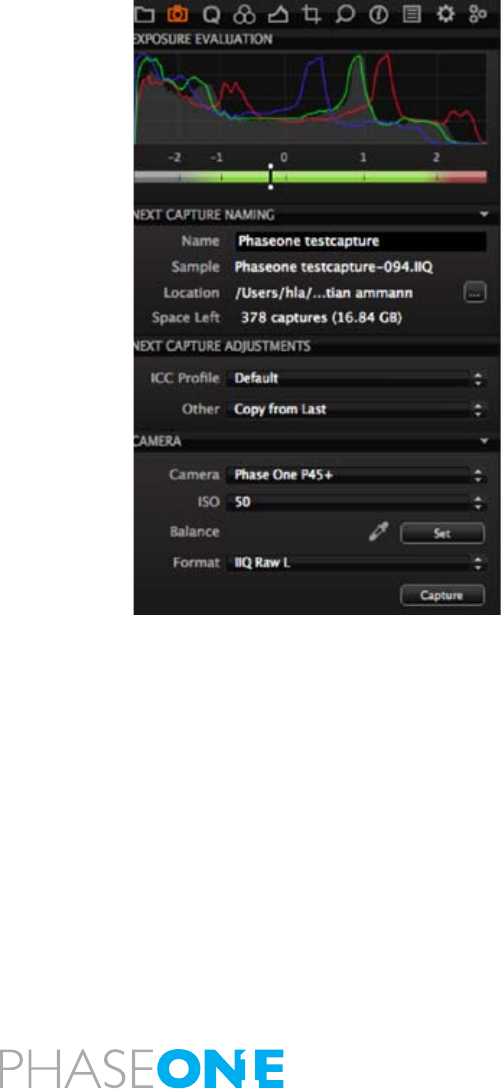
94
9.0 Software
Capture One 4.1 Digital Back Only, is a part of the new Phase One
camera platform.
For further information regarding functions of Capture One 4.1 please
read the users guide for this, the user guide is found under the menu
help on win and on MAC.
9.1 Getting started
The user interface of Capture One 4.1 is very close to the original Capture
One 4, you will nd the well known tabs Library, Quick, Color, Exposure,
Composition, Details, Adjustments, Meta, Process and Batch, besides
these we have added a new tab, Capture; this tab provides of course
the possibility of making the Capture via the connected FireWire cable.
You can control certain parts of the camera settings such as ISO format
and White Balance.
Read the software manual before using the software, and do test shots
before using the software for professional use.
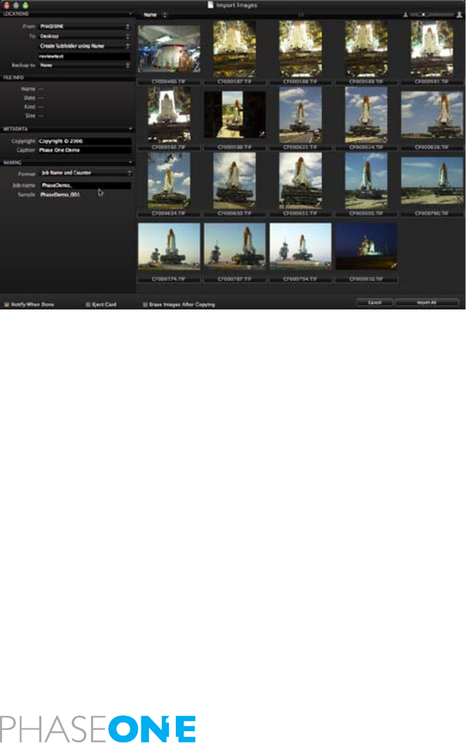
95
9.2 Importing from CF card
Like using e.g. win-explorer it is easy to browse to a disk containing
RAW images on a local or network computer. You can also choose to
import directly from a memory card in a card reader.
Choose File > Import images or select the import images button to begin
the import process. Immediately, a large dialogue box appears showing
a preview of les to be imported. This dialogue box also provides a
range of options form which to choose.
Inserting a memory card into a card reader will automatically bring
up the import dialogue window. The Import window offers a range of
options to make importing a quick and straightforward task.
It is important to remember that you are importing images from one
location to another. You need to create or dene a folder to which the
les will be imported to. This can be done manually or through the
Locations tab in the le importer window.
Capture One 4 can automatically create subfolders, named by date or
user dened. When importing you can also choose to rename the les,
as they are imported from the camera or cd/memorycard, the le names
can be changed by double-clicking on the lename in the browser or
when exporting the les.

96
10.0 Large format and technical cameras
Phase One’s status as open platform does not only mean the possibility
of tting the back on different medium format cameras, but also large
format and Technical cameras.
10.1 Large format photography
You can do large format photography, digital captures with the Phase
One back.
As the light sensitive chip in the P-back is not (yet!) 4x5” or 8x10 you
have to use an adapter to move the back to capture the entire view, the
FlexAdapter is a sliding back used to connect a Phase One back to a
large format camera. A ground glass is provided for initial set-up that
slides over to position the digital back in the perfect orientation to the
focused area.
Markings are provided for the stitching function which allows two
captures to be taken, beside each other with a slight overlap. Capture
One software automatically stitches these together with the built in
stitch tool.
The design is simple and clever, using a standard lens board mounted
on the back of the adapter for specic large format systems. Currently
there are versions for Sinar, Cambo, Arca Swiss, Linhof and Toyo
systems. Large format cameras that use a lens board for mounting the
ground glass assembly can be custom adapted (custom adaptation
service not provided by Phase One). All Phase One camera solutions
from the P 21+ to the P 45+ can be used with the FlexAdapter and all
backs can provide stitched images.
Capture One PRO provides stitch function to put the captures together
in one large format le; this is still used in architectural photography.
- Please read the specic largeformat leaets, and consult your local
dealer, you will be amazed of the possibilities.

97
10.2 Technical cameras
The use of technical cameras is growing. Images taken with a technical
camera can have different look and feel compared to DSLR or medium
format capture. The look is achieved through unique focal lengths, use
of rise/drop and shift movements available since photography began
and a different optical point of view.
For many photographers, quality cannot be compromised. A technical
camera provides signicantly more optical quality especially when
combined with a Phase One back and Capture One software. The
optical path is straight and simple with no mirror systems to worry
about. This removes the need of retro-focus design wide-angle lenses
that compromise image quality with DSLRs and mediumformat.
Both Rodenstock and Schneider have produced technical camera
lenses that are tuned to the capture area and quality requirements for
digital photography. A technical camera solution offers the sharpest
possible results.
For more information on technical photography consult your local
dealer.
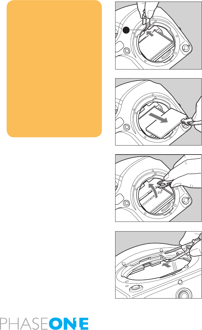
98
11.0 Maintenance
In general very little maintenance is needed, but this is a professional
tool, and should be treated with care and caution. If the gear for some
reason have not been used for a period, you should always do test
shots before the photographic session.
A frequently used product should be inspected periodically at the
nearest ofcial Phase One repair center. Should there be errors or
malfunctions of camera, lens or back – do NOT try to repair – consult
your local dealer.
11.1 changing the focusing screen
1. Remove the lens.
2. Pull the Focusing Screen Release lever A forward, as illustrated, with
the tweezers to let the Focusing Screen down.
3. Remove the Focusing Screen from the Focusing Screen Frame
by grasping the tab on the edge of the screen with tweezers as
illustrated.
4. When installing the screen, pinch the tab of the screen with tweezers,
and put the screen on the screen frame.
5. Push up the screen frame using the tweezers until hearing a clicking
sound. The screen is now properly installed. - Never press down on
other parts as this will affect the focus function.
NOTICE
Since the Focusing Screens’ surfaces
are soft and easily damaged, handle
them carefully.
Never touch the surface with bare
fingers. Should dust settle on it,
merely blow away by using a blower.
If the Focusing Screen needs
cleaning, send it to the nearest
authorized Phase One service center.
Do not attempt to clean the surface
of the Focusing Screen, as it is very
delicate.
Do not touch and damage the mirror
in any way.
A
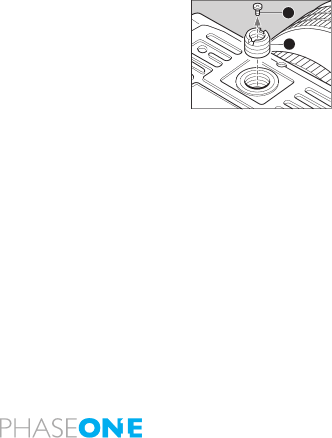
99
11.2 Battery socket
Never leave batteries in the socket, if the camera or back is not supposed
to be used for longer periods.
Keep contacts clean and dry at all times.
11.3 Tripod/Electronic shutter release contact
Keep all contact clean and dry at all time.
When using a tripod with 3/8” screw (instead of 1/4” screw) remove the
small screw A from the tripod screw hole on the bottom of the body
using a plus screwdriver, then use a coin to remove the tripod screw
adapter bushing B.
You will nd Electronic shutter release both on the camera body and on
the back. When used, it is recommendable to use the shutter release
on the back. Keep both contacts dry and clean.
A
B
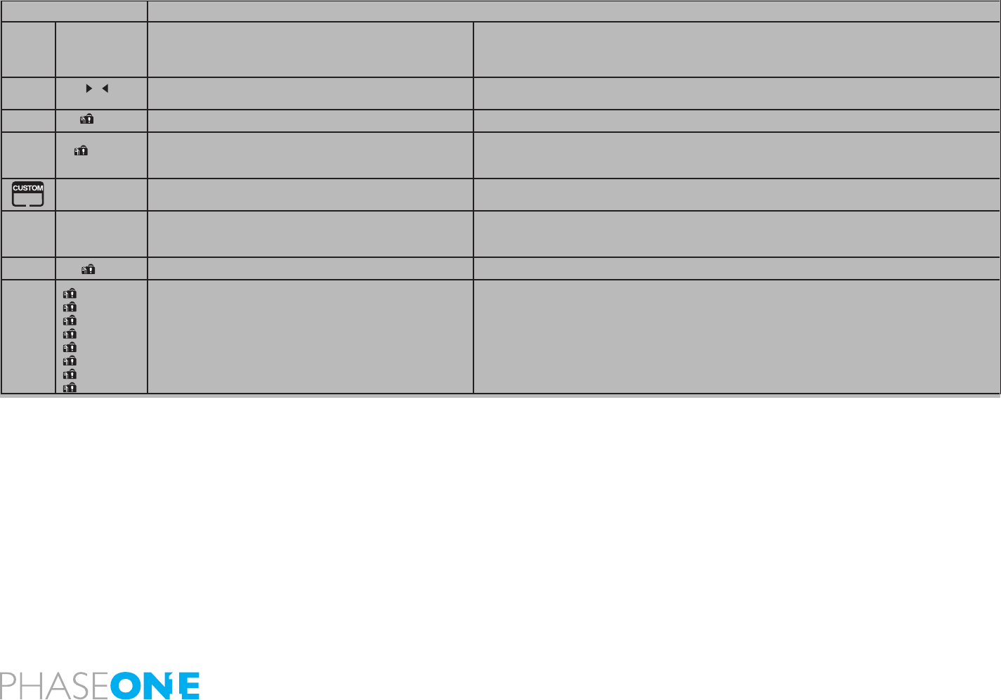
100
11.4 Camera display error-notification
LCD Display Causes and Remedies
Main
LCD
panel
Viewfinder
LCD
readouts
Problems Remedies
If the camera cannot focus in the AF “S” (single) mode, you
cannot release the shutter.
Try to adjust focus again, or change to the focus lock mode or manual focus mode
The indicator appears when the battery capacity is low. Replace with new batteries
The shutter will not operate when the digital back is not
mounted on the body. If you press the shutter release, this
symbol will appear.
Mount a digital back.
This symbol appears when setting the custom functions but
no choice of user is made.
Select a user before changing custom settings. CF-00
While in manual exposure mode, and when the difference
between the set value and metered value exceeds + or – 6EV,
this indicator will appear.
Change aperture or shutter speed.
This will appear when a lens is not mounted Try mounting a lens…!
When “Err” appears, some abnormality has been detected in
the course of taking photos.
Replace with new batteries and press the shutter release button, if the “Err” does not disappear then
contact your local dealer.
batt
batt
-no- Fb
-no- Fb
- u -
- o -
F- -
- -
Err- 01
Err- 02
Err- 03
Err- 04
Err- 05
Err- 06
Err- 07

101
11.5 Lens maintenance
Never touch the inner optics of the lens with your ngers, keep the
inneroptics perfectly clean with air, lens brush or the dry cloth delivered
with the lens.
Do not touch the contacts; keep the contacts clean, either by dry cloth
or by using berglass brush, do not use tools of any kind on the lens.
The lens is not waterproof, if wet it should be dried with a cloth, if
exposed to salt, moisten a cloth, wring it and clean.
11.6 Back Maintenance
Cleaning the CCD
When the Phase One P+ back is not attached to a camera, the camera
back must be protected with the protection plate. However, over time
dust may accumulate on the IR lter. This will degrade the image quality
if not removed.
Please follow the directions included in the CCD cleaning kit in the P+
back suitcase.

102
11.7 housing specification
Camera Type : 6x4.5cm format, electronically controlled focal-plane shutter, TTL multiple mode
AE, AF Single Lens Reex
Actual Image Size : 56x41.5 mm
Lens Mount : Mamiya 645 AF Mount, compatible with M645 Mount (manual focus conrmation,
focus aid, stopped-down exposure metering)
Viewfinder : Fixed prism viewnder magnication x0.71; built-in diopter adjustment (-2.5 to +0.5,
optional diopter correction lenses provide adjustment ranges of -5 to -2 diopter and 0
to +3 diopter); built-in eye-piece shutter
Focusing Screen : Interchangeable, Matte (standard), Checker, and Microprism Type C for Non-AF M645
lenses.
Field of View : 94%* of actual image
Viewfinder Info : Focus mark, defocus mark, warning mark, aperture value, shutter speed, metering
mode (A, S, A/S), exposure compensation value (difference between set value and
metered value) and ash ready / OK lamp with TTL Metz connection.
AF method : TTL phase difference detection method; sensor: CCD line sensor (I+I type); operating
range: EV0 to EV18 (ISO 100)
Focus area : Display the focus area in the viewnder screen
AF assist beam : Activates automatically under low light, low contrast.
Range: 9m, Automatic switching to ash unit’s built-in assist beam if Metz ash unit is attached.
AF Lock : By pressing the shutter release button halfway down in the AF-S mode, or by pressing
the AFL button.
Exposure Modes : Aperture-priority AE, shutter-priority AE, programmed AE (PH, PL setting possible),
and manual
AE metering mode : TTL metering, center-weighted average (AV), spot (S), and variable ratio (A-S auto)
Shutter increments : Both the shutter speed and the aperture level can be set to 1/3 or speed and aperture
1/2 using the electronic dial lock function
Metering Range : EV 2 to EV 19 (with ISO100 lm, f/2.8 lens)
Exp. comp. : ±3 EV (1/3 step) Expandable to ±5 EV
Film speed : ISO 25 to 6400
AE lock : With AEL button; canceled by pressing the button again or shutter release
Shutter : Electronically controlled vertical metal focal-plane shutter. (vertical travel)
Shutter speed : AE 30 to 1/4000 sec. (1/8 step), manual 30 to 1/4000 sec. (1/2 or 1/3 steps), X, B
(Bulb, electronically controlled), shutter curtain protection mechanism (open when
magazine is removed, automatically closed when magazine is attached)
Auto bracket shot : Enable with auto bracket button (2 frame shots, or 3 frame shot with auto bracketing).
Specify 1/3, 1/2, 2/3 or 1EV steps.
Flash Synchro : X contact point, 1/125 seconds (when 1/3 step is selected it can be set between 1/40 and
1/125 seconds).
Flash control : TTL direct ash control, supports Metz SCA3002 system (SCA3952 Adapter)
Multiple Exposure : Enable with multiple exposure button (the number of exposures can be set from 2 to 6). It
can be canceled in the middle and the number of exposures can be changed, or you can
switch to an arbitrary multiple exposure style.
Mirror up shot : Select by pressing the mirror up button.
LCD displays : Main LCD display: Program mode mark, custom function mode mark, AF area mark,
battery level indicator, manual focus mode, superimpose mode, dial lock mark, shutter
speed, AE lock mark, aperture value, multiple exposure mode mark, exposure
compensation mode mark, ash compensation mark, exposure compensation
value, self-timer mark, auto bracket mark, time mark (while setting the clock).
Data Imprinting : 7 segment dot matrix; DATA mode: exposure mode, aperture value, shutter speed value,
exposure compensation, metering mode, ID number; DAY mode; year, month, date, time,
ID number, ID mode; ID number
Sync terminal : X contact (sync speed 1/125 sec.)
Cable release : On shutter button
Remote terminal : On side of body; electromagnetic cable release
Self-Timer : 2 to 60 sec. (standard: 10 sec., can be set in 1 sec. steps between 2 and 10 sec., and in
10 sec. steps between 10 and 60 sec.)
Depth-of-field confirmation : Preview Button on body
Custom settings : 35 items + Firmware Information
Tripod Socket : U 1/4 inch and U 3/8 included
Power Requirements : 6 AA-size batteries (alkaline-magnesium, lithium)
External power socket : An external battery case can be connected.
Size & Weight : 6 ”(W)X5 ”(H)X7.3 ”(D) / 153(W)X128(H)X184(D)mm : 3.8 pounds / 1,730 g (W/O battery)
* This information is based on a linear (horizontal/vertical) measurement.
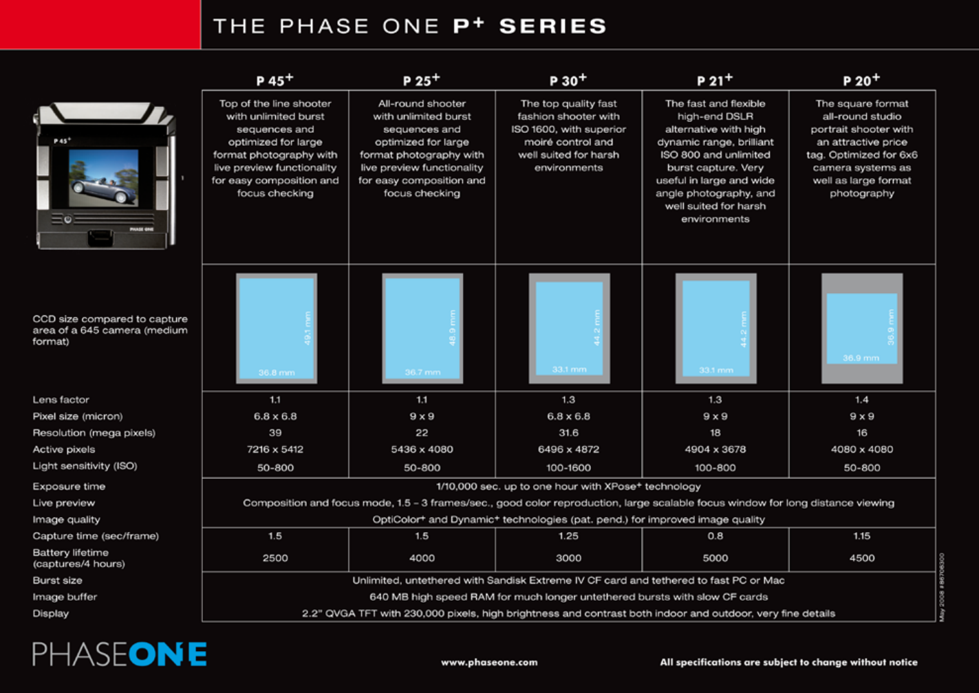
103
11.8 P+ series Technical specifications
Please read the schedule for detailed overview of the different backs.

104
11.9 End User support Policy
Please check www.phaseone.com for updated support policy
By purchase of a Phase One product we guarantee you World Class
Support and Service!
World Wide Dealer Network
At Phase One we think globally but act locally. Phase One’s products
are sold through a world wide network of dedicated and competent
local partners to make after-sales support convenient for you.
Phase One’s local partners offer rst line support to their customers.
Many provide additional services such as training, extended warranty
agreements, upgrade programs, and many other services that will add
value to your Phase One investment. Contact your local Phase One
partner to discuss your options. Digital camera back pricing and repairs
are also handled locally.
If there is no local partner in your area, then please contact Phase One
directly, and we will assist you directly or through one of our partners.
Find your local Phase One partner or take advantage of Phase One’s
wide range of on-line support tools at http://support.phaseone.com.

105
FAQ, Tutorials & Documentation
The FAQ is a collection of the most frequently asked questions and related answers in
the Phase One Knowledge Base. Use the FAQ as the first and best place to find answers
on many technical questions. If you are seeking more detailed information about Capture
One, Portrait One, or our Digital Backs, you can download user guides and manuals or
watch some of the tutorials available.
Knowledge Base
Phase One’s searchable Knowledge Base at http://support.phaseone.com provides you
with detailed answers to most of your questions. This ‘self-service’ site is free of charge
and available to all Phase One owners.
Capture One On-line Support Forums
On Phase One’s official support forum you may share your experiences and get assistance
from other Phase One owners as well as from Phase One’s Technical Support team. Some
Phase One partners offer on-line support forums, hosted from their own web pages.
Please note that these forums are governed by separate rules. Phase One offers no
guarantees and assumes no responsibility or liability with respect to the support provided
by our local partners.
On-Line Support
You can contact Phase One Technical Support directly by creating an on-line support case
on http://support.phaseone.com
Phase One Technical Support will do it’s best to answer your question as quickly as
possible.
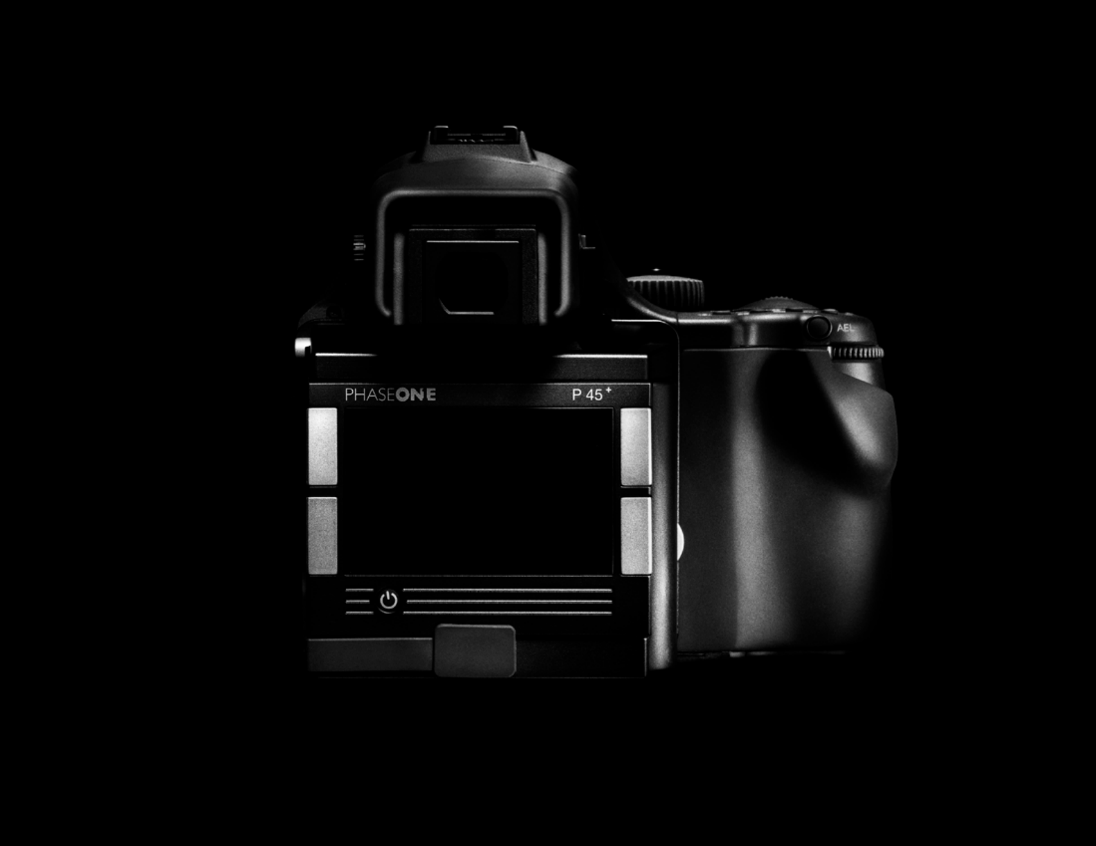
106
