Pismolabs Technology P1375 Pepwave / Peplink / Pismo Wireless Product User Manual Pepwave MAX
Pismo Labs Technology Limited Pepwave / Peplink / Pismo Wireless Product Pepwave MAX
Contents
- 1. User Manual (1 of 2).pdf
- 2. User Manual (2 of 2).pdf
User Manual (1 of 2).pdf
COPYRIGHT & TRADEMARKS
Specifications are subject to change without notice. Copyright © 2014 Pepwave Ltd. All Rights Reserved. Pepwave and the
Pepwave logo are trademarks of Pepwave Ltd. Other brands or products mentioned may be trademarks or registered
trademarks of their respective owners.
PepwaveMAX Series:
MAX 700 / HD2 /HD2 IP67 / BR1/ On-The-Go
Pepwave MAX Firmware 6.1
March 2014

http://www.pepwave.com
2
Copyright @ 2014 Pepwave
Table of Contents
1 INTRODUCTION AND SCOPE ................................................................................................. 5
2 GLOSSARY ............................................................................................................................. 6
3 PRODUCT FEATURES ............................................................................................................. 7
3.1 SUPPORTED NETWORK FEATURES ........................................................................................................ 7
3.2 OTHER SUPPORTED FEATURES ............................................................................................................ 8
4 PEPWAVE MAX MOBILE ROUTER OVERVIEW ..................................................................... 10
4.1 MAX 700 ................................................................................................................................... 10
4.2 MAX HD2 .................................................................................................................................. 12
4.3 MAX HD2 IP67 ........................................................................................................................... 14
4.4 MAX BR1 ................................................................................................................................... 16
4.5 MAX ON-THE-GO......................................................................................................................... 19
5 INSTALLATION .................................................................................................................... 21
5.1 PREPARATION ............................................................................................................................... 21
5.2 CONSTRUCTING THE NETWORK ......................................................................................................... 21
5.3 CONFIGURING THE NETWORK ENVIRONMENT ....................................................................................... 22
5.4 MOUNTING THE UNIT ..................................................................................................................... 22
6 CONNECTING TO WEB ADMIN INTERFACE ......................................................................... 23
7 CONFIGURATION OF LAN INTERFACE(S) ............................................................................. 25
7.1 BASIC SETTINGS............................................................................................................................. 25
7.2 CAPTIVE PORTAL ........................................................................................................................... 30
8 CONFIGURATION OF WAN INTERFACE(S) ........................................................................... 33
8.1 ETHERNET WAN ........................................................................................................................... 34
8.2 CELLULAR WAN ............................................................................................................................ 42
8.3 WI-FI WAN................................................................................................................................. 46
8.4 WAN HEALTH CHECK ..................................................................................................................... 50
8.5 BANDWIDTH ALLOWANCE MONITOR .................................................................................................. 53
8.6 DYNAMIC DNS SETTINGS ................................................................................................................ 54
9 ADVANCED WI-FI SETTINGS ................................................................................................ 56
10 BANDWIDTH BONDING SPEEDFUSIONTM ............................................................................ 59
10.1 PEPVPN ..................................................................................................................................... 59
10.2 PEPWAVE MAX BEHIND NAT ROUTER ............................................................................................... 65
10.3 SPEEDFUSIONTM STATUS ................................................................................................................. 66
11 IPSEC VPN ........................................................................................................................... 67
11.1 IPSEC VPN SETTINGS ..................................................................................................................... 67
12 MANAGEMENT OF OUTBOUND TRAFFIC TO WAN ............................................................. 70
12.1 OUTBOUND POLICY ........................................................................................................................ 71
12.2 CUSTOM RULES FOR OUTBOUND POLICY ............................................................................................. 72

http://www.pepwave.com
3
Copyright @ 2014 Pepwave
13 PORT FORWARDING ........................................................................................................... 80
13.1 PORT FORWARDING SERVICE ............................................................................................................ 80
14 NAT MAPPINGS .................................................................................................................. 83
15 QOS
15.1 USER GROUPS .............................................................................................................................. 85
15.2 BANDWIDTH CONTROL .................................................................................................................... 86
15.3 APPLICATION ................................................................................................................................ 87
16 FIREWALL ............................................................................................................................ 89
16.1 OUTBOUND AND INBOUND FIREWALL ................................................................................................. 89
17 MISCELLANEOUS SETTINGS ................................................................................................ 95
17.1 HIGH AVAILABILITY......................................................................................................................... 95
17.2 PPTP SERVER ............................................................................................................................... 98
17.3 CERTIFICATE MANAGER ................................................................................................................... 99
17.4 SERVICE FORWARDING .................................................................................................................. 100
17.5 SERVICE PASSTHROUGH ................................................................................................................. 103
18 AP
18.1 WIRELESS SSID ........................................................................................................................... 104
18.2 SETTINGS ................................................................................................................................... 105
18.3 TOOLBOX ................................................................................................................................... 107
19 SYSTEM SETTINGS ............................................................................................................. 108
19.1 ADMIN SECURITY ......................................................................................................................... 108
19.2 FIRMWARE UPGRADE ................................................................................................................... 112
19.3 TIME ........................................................................................................................................ 113
19.4 EMAIL NOTIFICATION .................................................................................................................... 113
19.5 EVENTLOG ................................................................................................................................. 116
19.6 SNMP ...................................................................................................................................... 117
19.7 INCONTROL ................................................................................................................................ 119
19.8 CONFIGURATION ......................................................................................................................... 120
19.9 FEATURE ADD-ONS ...................................................................................................................... 121
19.10 REBOOT .................................................................................................................................... 121
19.11 PING TEST.................................................................................................................................. 122
19.12 TRACEROUTE TEST ....................................................................................................................... 123
19.13 PEPVPN TEST............................................................................................................................. 123
19.14 PEPVPN ANALYZER...................................................................................................................... 124
19.15 CLI (COMMAND LINE INTERFACE SUPPORT) ....................................................................................... 124
20 STATUS ............................................................................................................................. 125
20.1 DEVICE ...................................................................................................................................... 125
20.2 ACTIVE SESSIONS ......................................................................................................................... 127
20.3 CLIENT LIST ................................................................................................................................ 129
20.4 WINS CLIENT ............................................................................................................................. 130
20.5 SPEEDFUSIONTM .......................................................................................................................... 130
20.6 UPNP / NAT-PMP ..................................................................................................................... 131
20.7 EVENT LOG ................................................................................................................................ 132
20.8 BANDWIDTH ............................................................................................................................... 133

http://www.pepwave.com
4
Copyright @ 2014 Pepwave
APPENDIX A. RESTORATION OF FACTORY DEFAULTS ........................................................ 138
APPENDIX B. DECLARATION .............................................................................................. 139
http://www.pepwave.com
5
Copyright @ 2014 Pepwave
1 Introduction and Scope
The Pepwave MAX Mobile Router provides link aggregation and load balancing acrossmultiple WAN
connections, allowing a combination of technologies like 3G HSDPA, EVDO, 4G LTE, Wi-Fi, external
WiMAX dongle, and Satellite to be utilized to connect to the Internet.
This manual presents how to set up the Pepwave MAX Mobile Router and provides an introduction to
thefeatures and usage of Pepwave MAX Mobile Router.
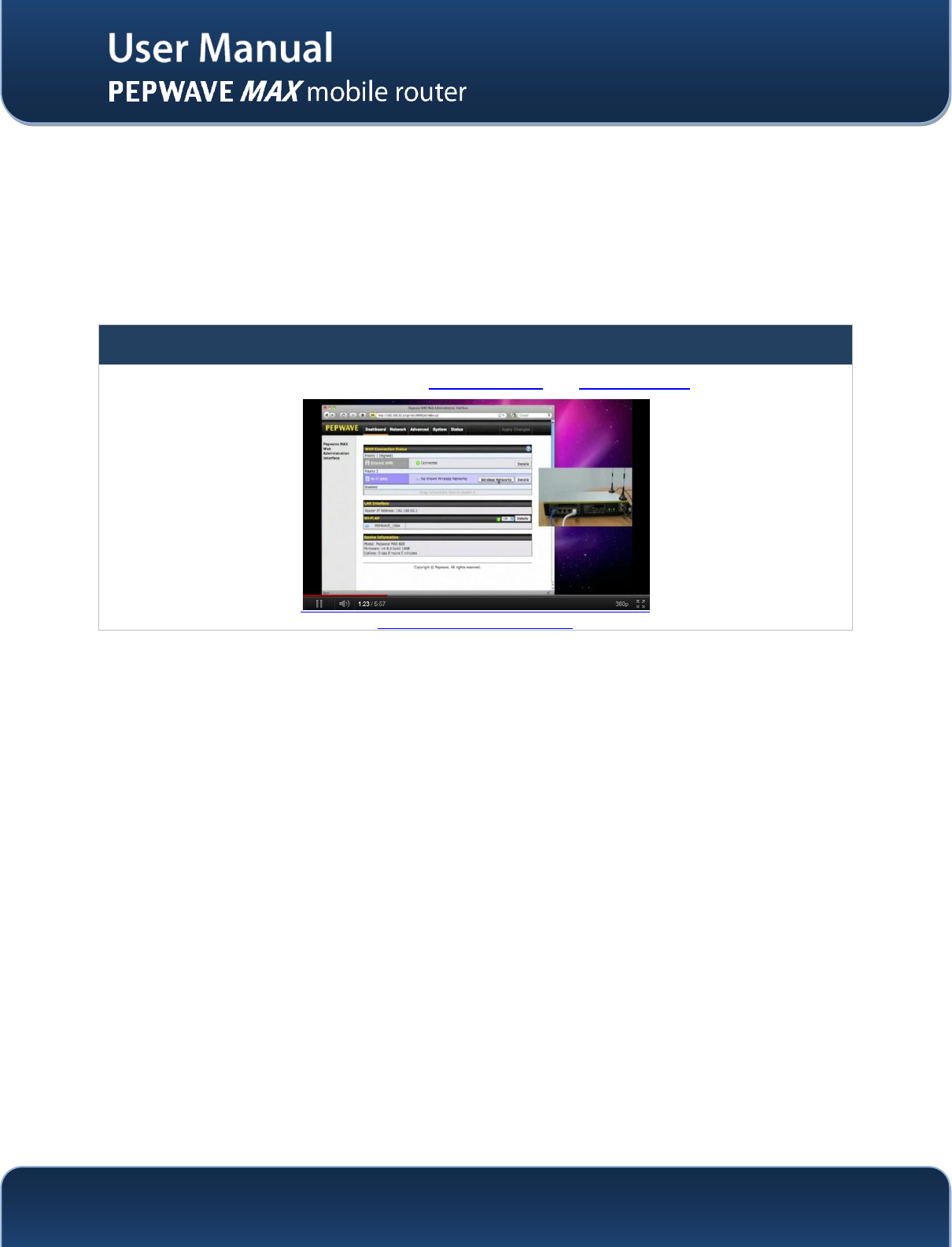
Tips
Want to know more about Pepwave MAX? Visit ourYouTube Channel for a video introduction!
http://youtu.be/UCkVQThLKO4
http://www.pepwave.com
6
Copyright @ 2014 Pepwave
2 Glossary
The following terms, acronyms, and abbreviations are frequently used in this manual:
Term
Definition
3G
3rd Generation standards for wireless communications (e.g. HSDPA)
4G
4th Generation standards for wireless communications (e.g. WiMAX, LTE)
DHCP
Dynamic Host Configuration Protocol
DNS
Domain Name System
EVDO
Evolution-Data Optimized
HSDPA
High-Speed Downlink Packet Access
HTTP
Hyper-Text Transfer Protocol
ICMP
Internet Control Message Protocol
IP
Internet Protocol
LAN
Local Area Network
MAC Address
Media Access Control Address
MTU
Maximum Transmission Unit
MSS
Maximum Segment Size
NAT
Network Address Translation
PPPoE
Point to Point Protocol over Ethernet
QoS
Quality of Service
SNMP
Simple Network Management Protocol
TCP
Transmission Control Protocol
UDP
User Datagram Protocol
VPN
Virtual Private Network
VRRP
Virtual Router Redundancy Protocol
WAN
Wide Area Network
WINS
Windows Internet Name Service
WLAN
Wireless Local Area Network

http://www.pepwave.com
7
Copyright @ 2014 Pepwave
3 Product Features
PepwaveMAX enables all LAN users to share broadband Internet connections, and provide advanced
features to enhance Internet access. The following is the list of supported features on Pepwave MAX
Mobile Router:
3.1 Supported Network Features
3.1.1 WAN
Ethernet WAN Connection in Full/Half Duplex
Static IP support for PPPoE
Built-in HSPA and EVDO cellular modems (Available on Pepwave MAX HD2 and HD2 IP67)
USB mobile connection(s)
Wi-Fi WAN connection
Network address translation (NAT)/ port address translation (PAT)
Inbound and outbound NATmapping
IPsec NAT-T and PPTP packet passthrough
MAC address clone and passthrough
Customizable MTU and MSS values
WAN connection health check
Dynamic DNS (supportedservice providers: changeip.com, dyndns.org, no-ip.org, tzo.com and
DNS-O-Matic)
Ping, DNS lookup and HTTP based health check
3.1.2 LAN
Wi-Fi AP
Ethernet LAN ports
DHCP server on LAN
Extended DHCP option support
Static routing rules
VLAN on LAN support
3.1.3 VPN
SpeedFusionTM
SpeedFusion performance analyzer
X.509 certificate support (supported forMAX 700, and MAX HD2, available on the Max BR1
and MAX_OTG_U4_SF as an activated feature)
VPN load balancing and failover among selected WAN connections
Bandwidth bonding & failover among selected WAN connections
IPsec VPN for Network-to-Network connection (Works with Cisco, Juniper only)
Ability to route Internet traffic to a remote VPN peer
Optional pre-shared key setting
SpeedFusionTMthroughput, ping and traceroute tests
PPTP server

http://www.pepwave.com
8
Copyright @ 2014 Pepwave
PPTP and IPsec passthrough
3.1.4 Firewall
Outbound (LAN to WAN) firewall rules
Inbound (WAN to LAN) firewall rules per WAN connection
Intrusion detection and prevention
Specification of NAT mappings
Outbound firewall rules can be defined by destination domain name
3.1.5 Captive Portal
Splash screen of open networks, login page for secure networks
Customizable built-in captive portal
Supports linking to outside page for captive portal
3.1.6 Outbound Policy
Link load distribution per TCP/UDP service
Persistent routing for specified source and/or destination IP addresses per TCP/UDP service
Traffic Prioritization and DSL optimization
Prioritize and route traffic to VPN tunnels with Priority and Enforced algorithms
3.1.7 AP Controller(Available on the Pepwave MAX 700 and MAX HD2)
Configure and manage Pepwave AP devices
Review the status of connected AP
3.1.8 QoS
Quality of Service for different applications and custom protocols
User Group classification for different service levels
Bandwidth usage control and monitoring on group- and user- level
Application Prioritization for custom protocols and DSL/Cable optimization
3.2 Other Supported Features
User-friendly web-based administration interface
HTTP and HTTPS support for Web Admin Interface
Configurable web administration port and administrator password
Firmware upgrades, configuration backups, Ping, and Traceroute via Web Admin Interface
Remote web based configuration (via WAN and LAN interfaces)
Time server synchronization
SNMP
Email notification

http://www.pepwave.com
9
Copyright @ 2014 Pepwave
Read-only user for Web Admin
SharedIP drop-in mode (Available on the Pepwave MAX 700 and MAX HD2)
Authentication and Accounting by RADIUS server for Web Admin
Built-in WINS Servers
Syslog
SIP passthrough
PPTP packet passthrough
Event Log
Active Sessions
Client List
WINS Client List
UPnP / NAT-PMP
Real-Time, Hourly, Daily and Monthly Bandwidth Usage reports and charts
IPv6 support(Available on Pepwave MAX 700, HD2 and HD2 IP67)
Support USB tethering on Android 2.2+ phones
http://www.pepwave.com
10
Copyright @ 2014 Pepwave
4 Pepwave MAX Mobile Router Overview
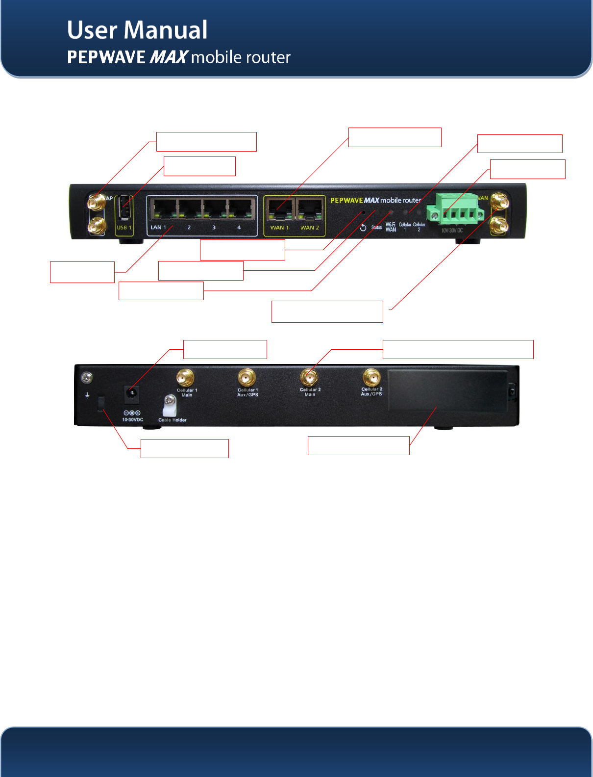
4.1 MAX 700
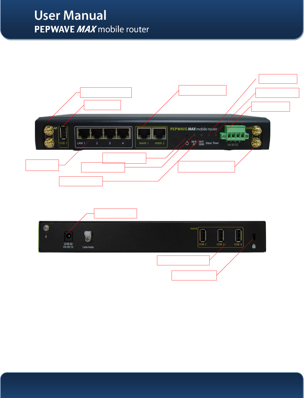
4.1.1 Front Panel Appearance
4.1.2 Rear Panel Appearance
LAN Ports
Ethernet WAN Port
Wi-Fi WAN Connector
Wi-Fi LAN Connector
USB Port
Wi-Fi AP LED
Wi-Fi WAN LED
Reset Button
Power LED
Terminal Block
Status LED
Power Connector
USB Ports
Kensington Lock
http://www.pepwave.com
11
Copyright @ 2014 Pepwave
4.1.3 LED Indicators
The statuses indicated by the front panel LEDs are as follows:
Status Indicators
Status
OFF
System initializing
Red
Booting up or busy
Blinking red
Boot up error
Green
Ready
Wi-Fi AP and Wi-Fi WAN Indicators
Wi-Fi WAN
OFF
Disconnected
Blinking slowly
Connecting to network
Blinking
Connected to network with traffic
ON
Connected to network without traffic
Wi-Fi AP
OFF
Disabled
Blinking slowly
Enabled but no client connected
Blinking
Connected to network with traffic
ON
Client(s) connected to wireless network
LAN and Ethernet WAN Ports
Green LED
ON
10 / 100/ 1000 Mbps
Orange LED
Blinking
Data is transferring
OFF
No data is being transferred or port is not connected
Port Type
Auto MDI/MDI-X ports
http://www.pepwave.com
12
Copyright @ 2014 Pepwave
4.2 MAX HD2
4.2.1 Front Panel Appearance
4.2.2 Rear Panel Appearance
LAN Ports
Ethernet WAN Port
Wi-Fi WAN Connector
Wi-Fi AP Connector
USB Port
Status LED
Wi-Fi WAN LED
Reset Button
Cellular WAN LED
Terminal Block
Power Connector
Cellular SIM Slots
Kensington Lock
Cellular Antenna Connectors
http://www.pepwave.com
13
Copyright @ 2014 Pepwave
4.2.3 LED Indicators
The statuses indicated by the front panel LEDs are as follows:
Status Indicators
Status
OFF
System initializing
Red
Booting up or busy
Blinking red
Boot up error
Green
Ready
Wi-Fi AP and Wi-Fi WAN Indicators
Wi-Fi WAN /
Cellular 1 /
Cellular 2
OFF
Disabled Intermittent
Blinking slowly
Connecting to wireless network(s)
Blinking
Connected to wireless network(s) with traffic
ON
Connected to wireless network(s) without traffic
LAN and Ethernet WAN Ports
Green LED
ON
10 / 100 / 1000 Mbps
Orange LED
Blinking
Data is transferring
OFF
No data is being transferred or port is not connected
Port Type
Auto MDI/MDI-X ports
http://www.pepwave.com
14
Copyright @ 2014 Pepwave
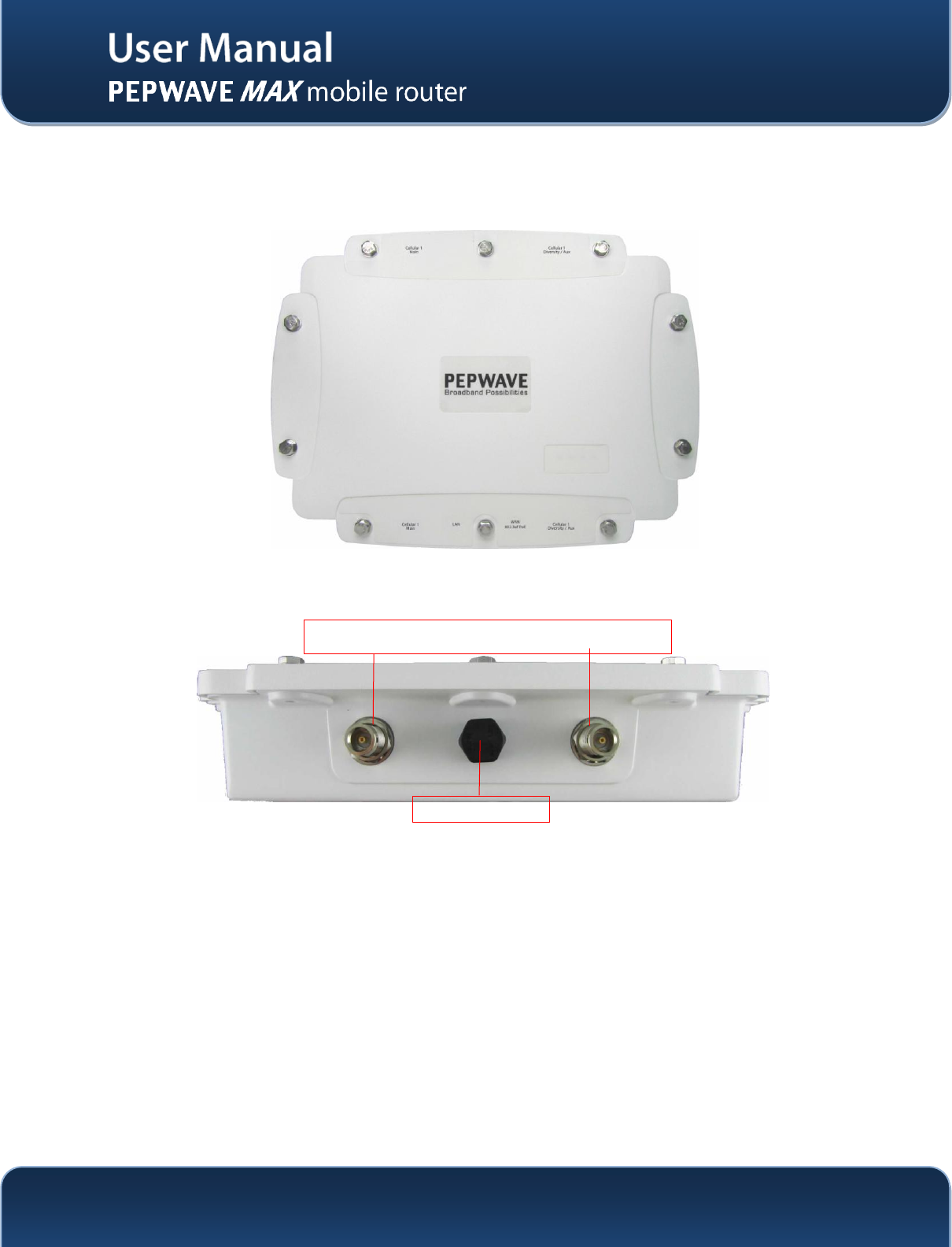
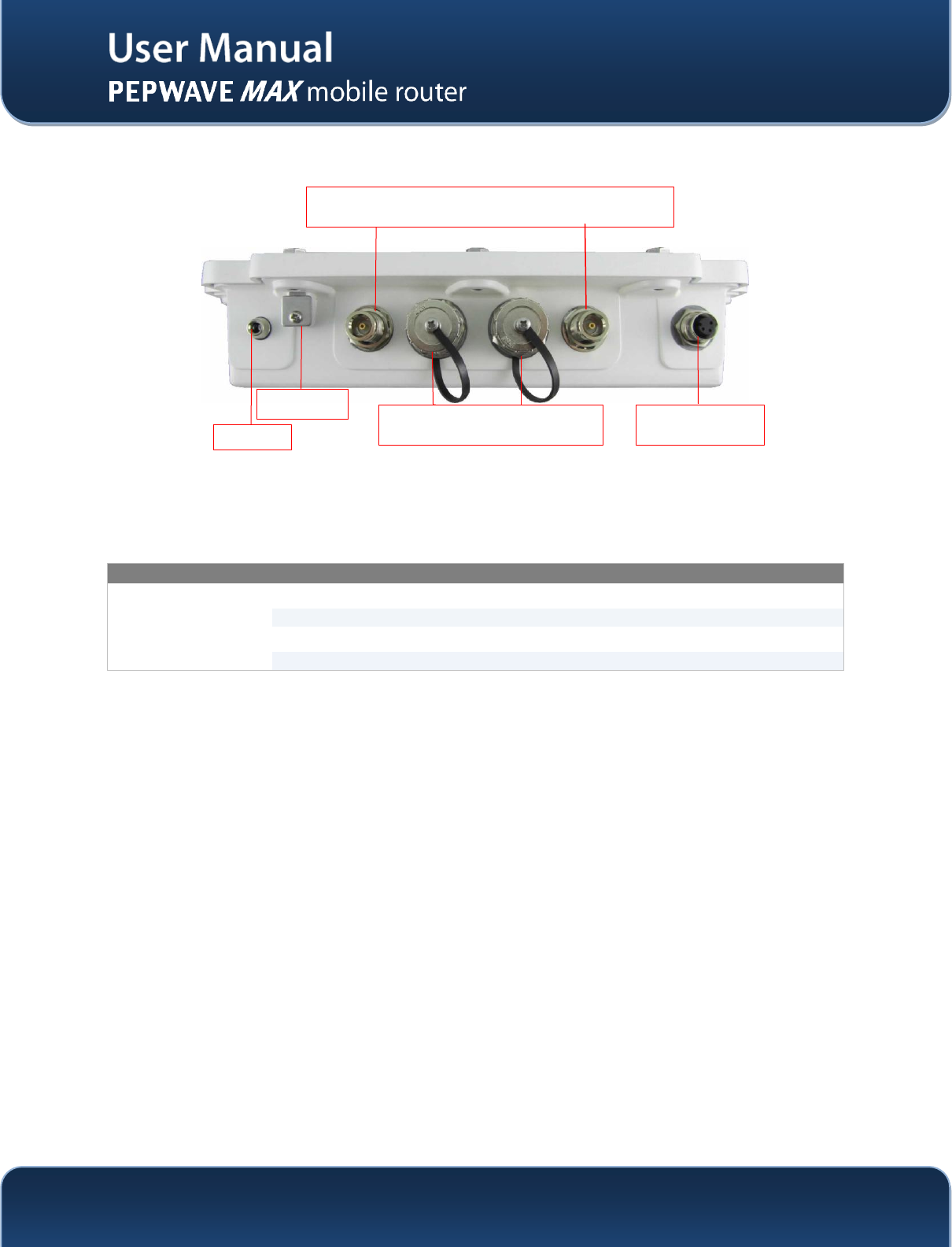
4.3 MAX HD2 IP67
4.3.1 Front Panel Appearance
4.3.2 TopPanelAppearance
2x Female N-Type Antenna Connectors for Cellular Connection
Waterproof Air Vent
http://www.pepwave.com
15
Copyright @ 2014 Pepwave
4.3.3 Rear Panel Appearance
The statuses indicated by the front panel LEDs are as follows:
Status Indicators
Status
OFF
System initializing
Red
Booting up or busy
Blinking red
Boot up error
Green
Ready
2x Female N-Type Antenna Connectors for Cellular Connection
Waterproof DC
Power Connector
Ground Plate
Waterproof Ethernet WAN and LAN
Status LED
http://www.pepwave.com
16
Copyright @ 2014 Pepwave
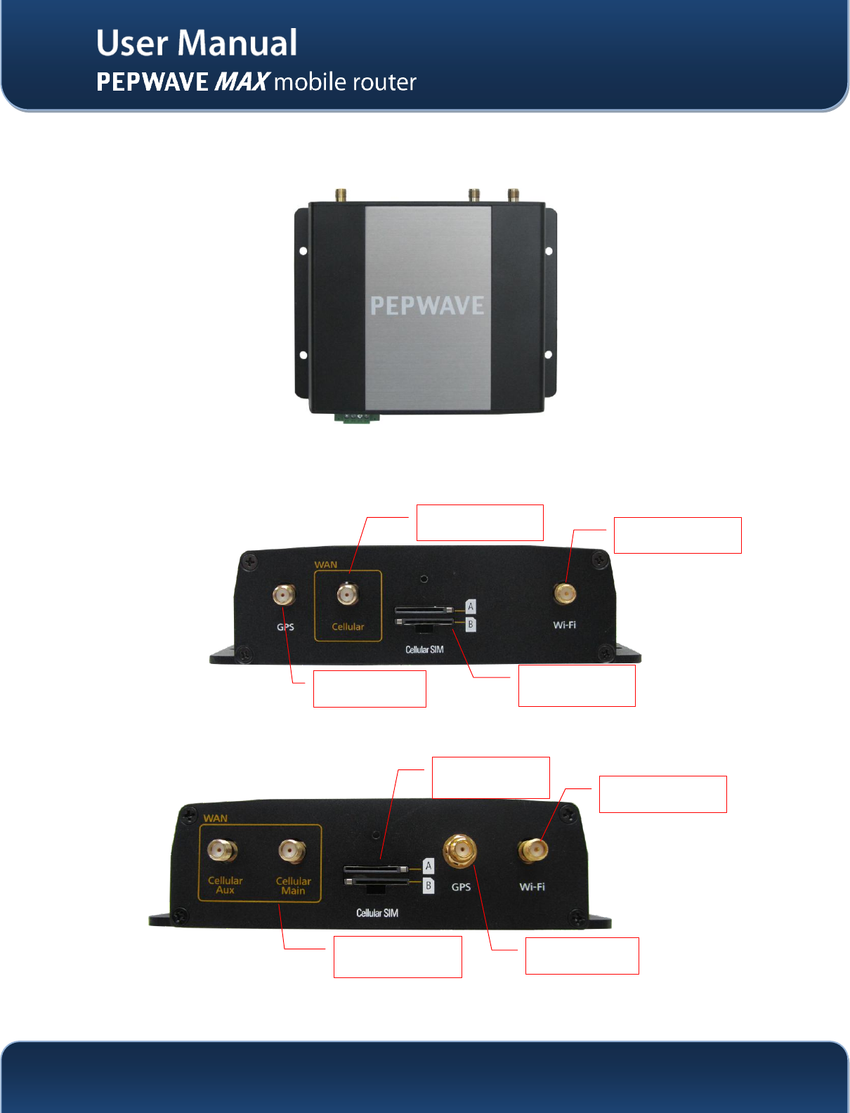
4.4 MAX BR1
4.4.1 Front Appearance
4.4.2 Top Panel Appearance
(MAX-BR1 Version)
(MAX-BR1-LTE Version)
RP-SMA Wi-Fi
Antenna Connector
SMA Cellular
Antenna Connector
SMA GPS Antenna
Connector
Redundant Cellular
SIM Slots
SMA GPS Antenna
Connector
Redundant Cellular
SIM Slots
SMA Cellular
Antenna Connectors
RP-SMA Wi-Fi
Antenna Connector
http://www.pepwave.com
17
Copyright @ 2014 Pepwave
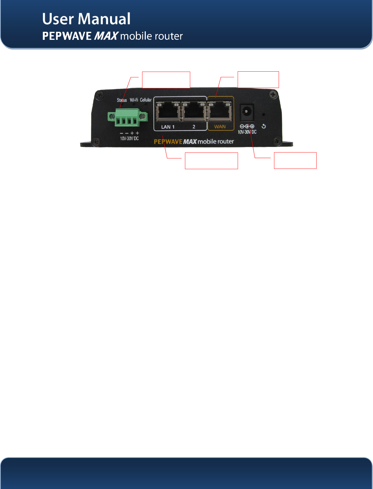
4.4.3 Rear Panel Appearance
Dual 10/100
Ethernet LAN
10 -30V DC
Terminal Block
10/100
Ethernet WAN
10 – 30V DC
Connector
http://www.pepwave.com
18
Copyright @ 2014 Pepwave
4.4.4 LED Indicators
The statuses indicated by the front panel LEDs are as follows:
Status Indicators
Status
OFF
System initializing
Red
Booting up or busy
Blinking red
Boot up error
Green
Ready
Wi-Fi Indicators
Wi-Fi
OFF
Disabled Intermittent
Blinking slowly
Connecting to wireless network(s)
Blinking
Connected to wireless network(s) with traffic
ON
Connected to wireless network(s) without traffic
Cellular Indicators
Cellular
OFF
Disabled or no SIM card inserted
ON
Connecting or connected to network(s)
LAN and Ethernet WAN Ports
Green LED
ON
100 Mbps
OFF
10 Mbps
Orange LED
ON
Port is connected without traffic
Blinking
Data is transferring
OFF
Port is not connected
Port Type
Auto MDI/MDI-X ports
http://www.pepwave.com
19
Copyright @ 2014 Pepwave
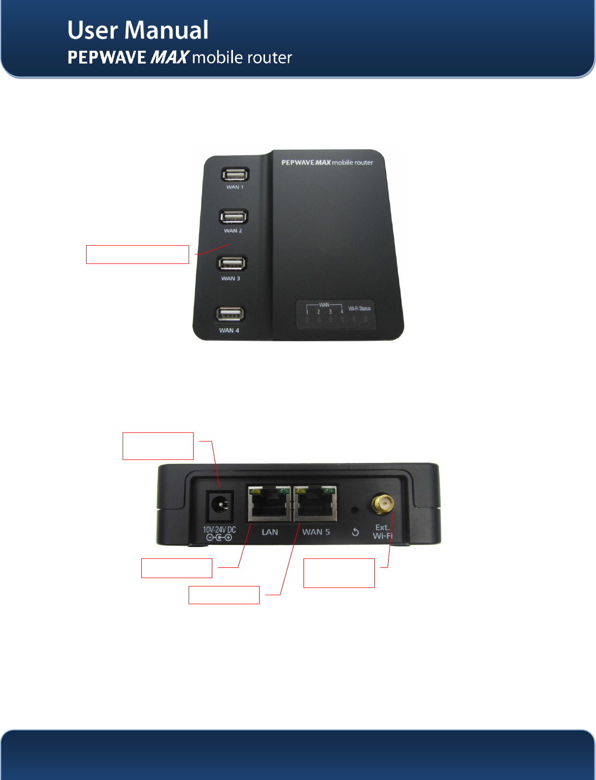
4.5 MAX On-The-Go
4.5.1 Top Panel Appearance
4.5.2 Rear Panel Appearance
USB WAN Ports
10 -24V DC
Terminal Block
LAN Port
Ethernet WAN
RP-SMA Wi-Fi
Antenna
Connector

http://www.pepwave.com
20
Copyright @ 2014 Pepwave
4.5.3 LED Indicators
The statuses indicated by the front panel LEDs are as follows:
Cellular Indicators
WAN
OFF
Modem is not attached to the port.
Green
Modem is attached to the port.
Wi-Fi Indicators
Wi-Fi
OFF
Disconnected to AP.
Green
Connected to AP.
Status Indicators
Status
OFF
System initializing
Red
Booting up or busy
Green
Ready
LAN and Ethernet WAN Ports
Green LED
ON
100 Mbps
OFF
10 Mbps
Orange LED
ON
Port is connected without traffic
Blinking
Data is transferring
Port Type
Auto MDI/MDI-X ports

http://www.pepwave.com
21
Copyright @ 2014 Pepwave
5 Installation
The following section details connecting the Pepwave MAX Mobile Router to your network:
5.1 Preparation
Before installingyour Pepwave MAX Mobile Router, please prepare the following:
At least one Internet/WAN access account and/or Wi-Fi access information.
For each network connection,
Ethernet WAN: A 10/100/1000BaseT UTP cable with RJ45 connector
USB: A USB modem
Embedded Modem: A SIM card for GSM/HSPA service
Wi-Fi WAN: Wi-Fi antennas
PC Card / Express Card WAN:A PC Card/ExpressCard for the corresponding card slot.
A computer with TCP/IP network protocol and a web browser installed. Supported browsers
include Microsoft Internet Explorer 8.0 or above, Mozilla Firefox 10.0 or above, Apple Safari 5.1
or above, and Google Chrome 18 or above.
5.2 Constructing the Network
At the high level, construct the network according to the following steps:
1. With an Ethernet cable, connect a computer to one of the LAN ports on thePepwave MAX.
Repeat with different cables for up to 4 computers to be connected.
2. With another Ethernet cable or a USB modem / Wi-Fi antenna / PC Card / Express Card,
connect it to one of the WAN ports on the Pepwave MAX. Repeat the same procedure for
other WAN ports.
3. Connect the power adapter to the power connector on the rear panel ofthe Pepwave MAX,
and then plug it into a power outlet.
The following figure schematically illustrates the configuration that results:
http://www.pepwave.com
22
Copyright @ 2014 Pepwave
5.3 Configuring the Network Environment
To ensure that the Pepwave MAX works properly in the LAN environment and can access the Internet via
the WAN connections, please refer to the following setup procedures:
LAN Configuration
For basic configuration, refer to Section6,Connecting to Web Admin Interface.
For advanced configuration, go to Section7, Configuration of LAN Interface(s).
WAN Configuration
For basic configuration, refer to Section6, Connecting to Web Admin Interface.
For advanced configuration, go to Section 7.2,Captive Portal
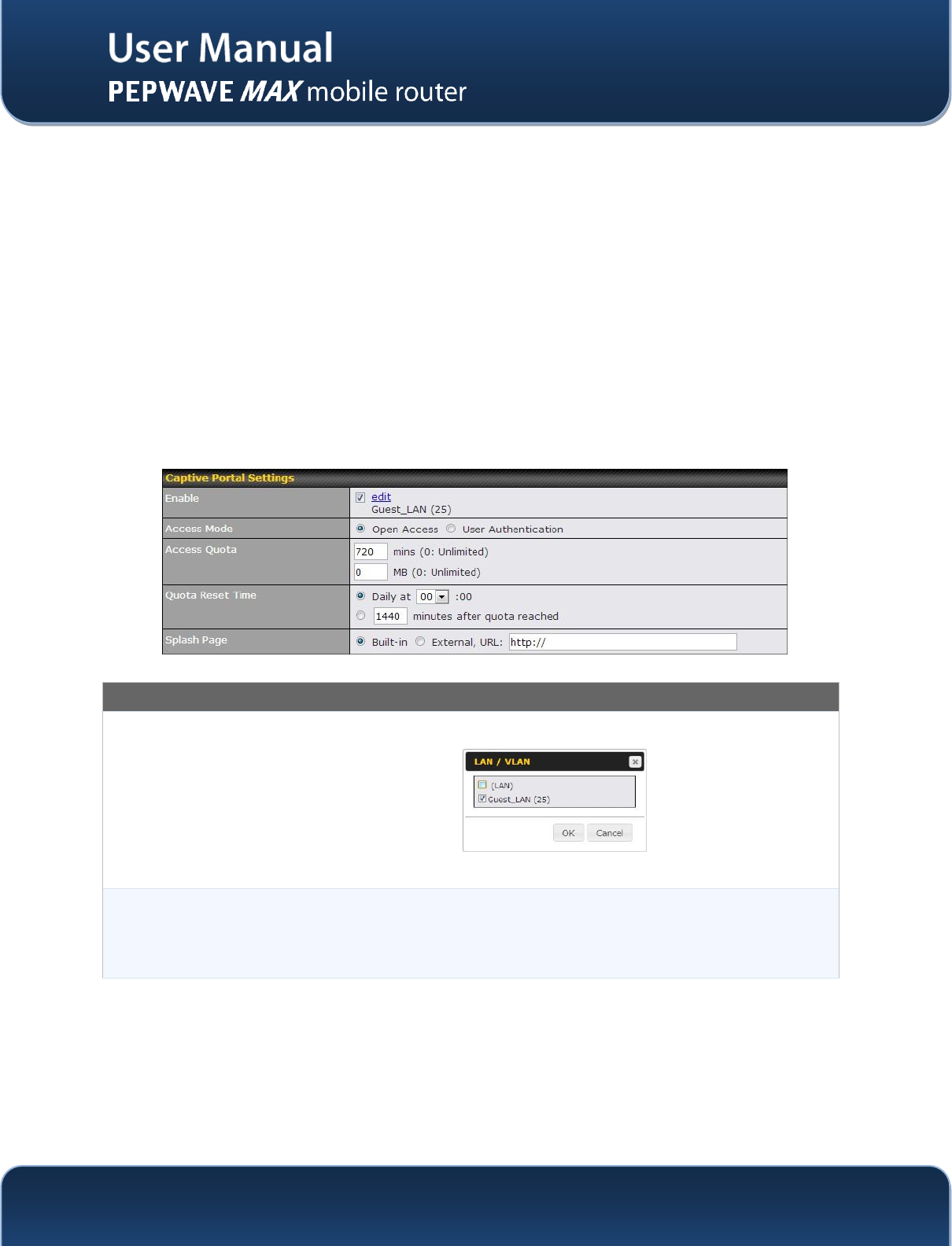
The Captive Portal serves as gateway that clients have to pass if they wish to access the internet
using your router. To configure, navigate to Network >Captive Portal to see the following screen:
Captive Portal Settings
Apply On
Clicking the edit button trigger a dialogue where you can choose which LAN / VLAN to
apply your captive portal.
Click all LAN / VLAN that you wish to apply the captive portal to.
Access Mode
Click Open Access to allow clients to freely access your router. Click User
Authentication to force your clients to authenticate before accessing your router.
http://www.pepwave.com
23
Copyright @ 2014 Pepwave
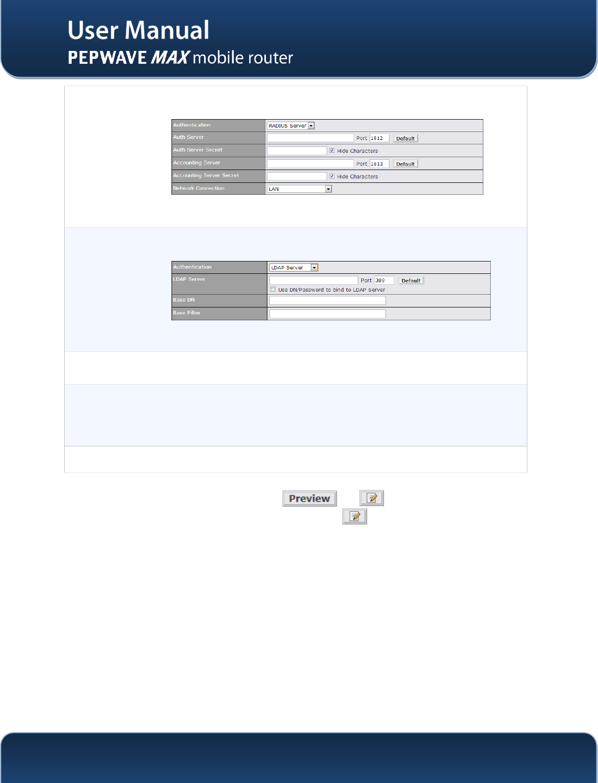
Radius
Server
This authenticates your clients through a Radius Server. Upon selecting this option, you
will see the following fields:
Fill in the necessary information to complete your connection to the server and enable
authentication.
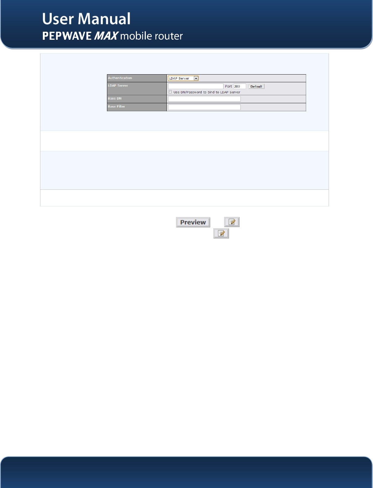
LDAP Server
This authenticates your clients through a LDAP Server. Upon selecting this option, you
will see the following fields:
Fill in the necessary information to complete your connection to the server and enable
authentication.
Access
Quota
Set a time and data cap to each user’s Internet usage.
Quota Reset
Time
This menu determines how your usage quota resets. Setting it to daily will reset it at a
specified time every day. Setting a number of minutes after quota reached establish a
timer for each user that begins after the quota has been reached.
Splash Page
Here, you can choose between using the MAX router’s built-in captive portal and
redirecting clients to a URL you define.
The Portal Customization menu has two options: and . Clicking will result in a pop-up
previewing the captive portal that your clients will see. Clicking will result in the appearance of
following menu:

http://www.pepwave.com
24
Copyright @ 2014 Pepwave
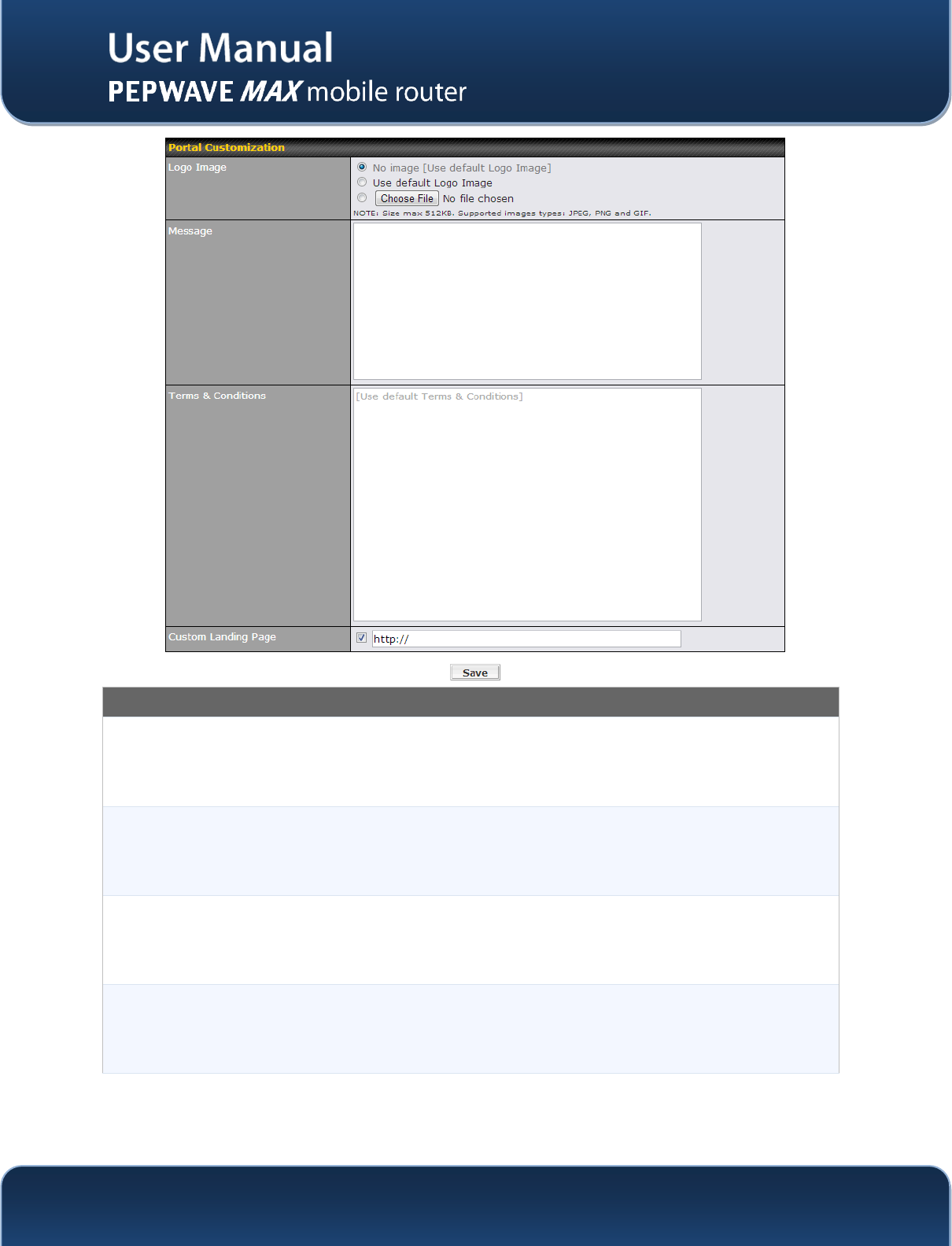
Portal Customization
Logo Image
Click the Choose File button to select an logo to use for the built-in portal
Message
If you have any additional messages for your users, place it on this field.
Terms &
Conditions
If you would like to use your own set of terms and conditions, please place it here. If left
empty, the built-in portal will display the default terms and conditions.
Custom
Landing
Page
Fill in this field to redirect clients to an external URL.
http://www.pepwave.com
25
Copyright @ 2014 Pepwave
6 Configuration of WAN Interface(s)
.
6.1 Mounting the Unit
6.1.1 Wall Mount
The Pepwave MAX 700/HD2/On-The-Go can be mounted on the wall by screwing. After adding the screw
on the wall, slide the MAX in the screw whole socket as indicated below.Recommeneded Screw
Specification: M3.5 x 20mm, Head Diameter 6mm, Head Thickness 2.4mm
The Pepwave MAX BR1 can be mountedby screwing the four holes on the device to the wall.
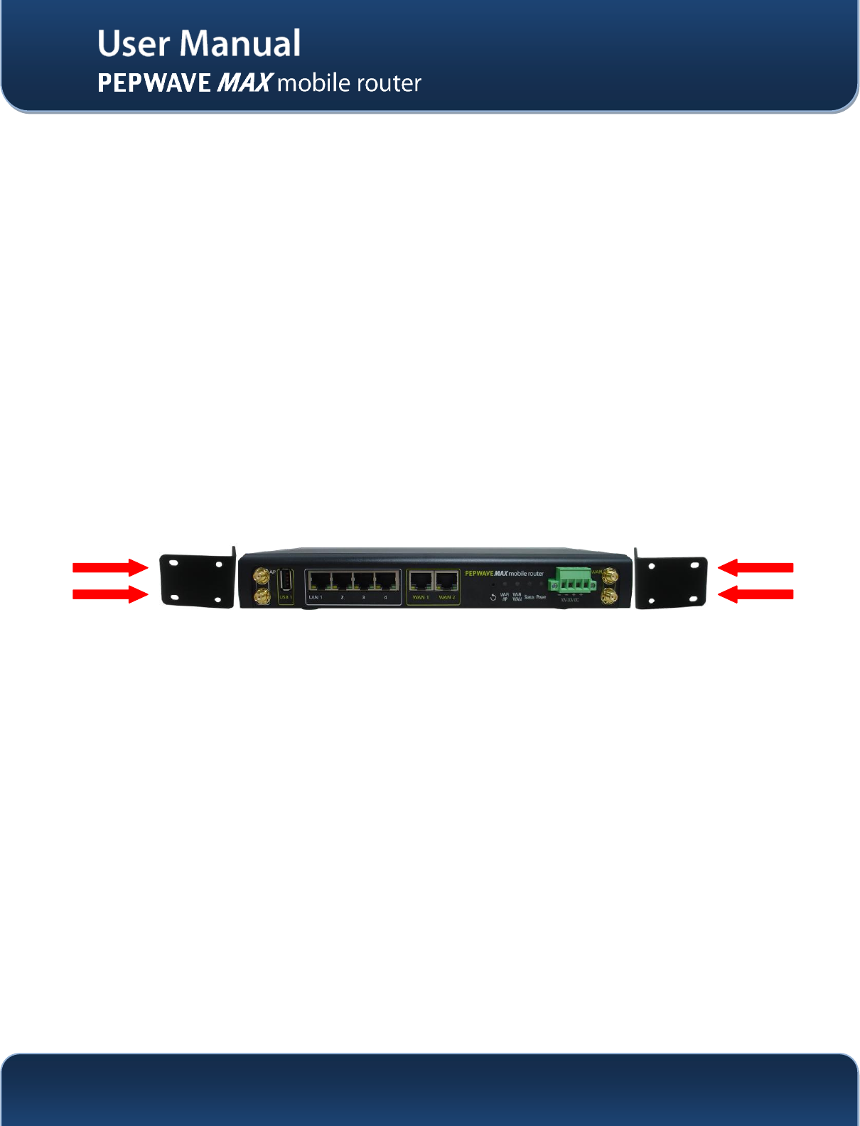
6.1.2 Car Mount
The Pepwave MAX700/HD2 can be mounted in a vehicle using the included mounting brackets. Place the
mounting brackets by the two sides, and screw it onto the device.
7 Connecting to Web Admin Interface
1. Start a Web browser on a computer that is connected with the Pepwave MAX through LAN.
2. To connect to Web Admin Interface of the Pepwave MAX, enter the following LAN IP address in the
address field of the web browser:
http://192.168.50.1
http://www.pepwave.com
26
Copyright @ 2014 Pepwave
(This is the default LAN IP address of the Pepwave MAX.)
3. Enter the following to access the Web Admin
Interface.
Username: admin
Password: admin
(This is the default Username and Password of
the Pepwave MAX. The Admin and Read-only
User Password can be changed at System >
Admin Security of the Web Admin Interface.)
http://www.pepwave.com
27
Copyright @ 2014 Pepwave
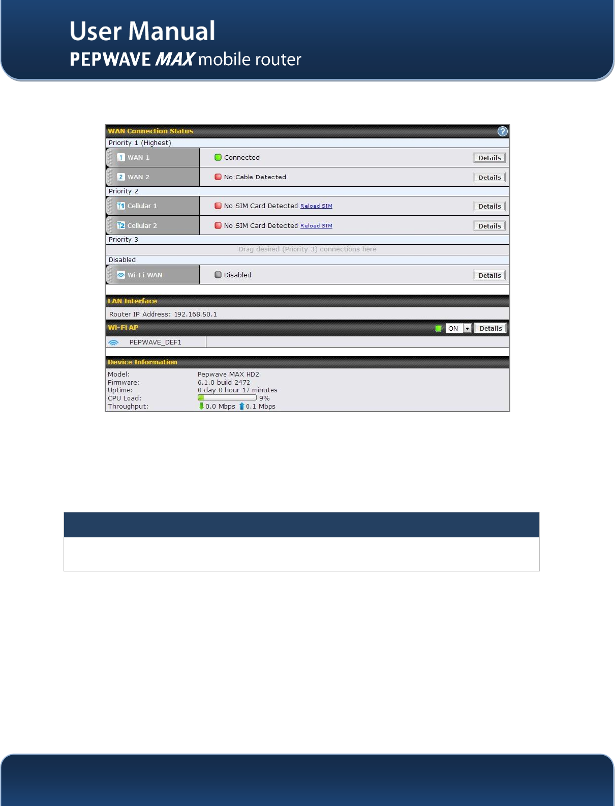
4. After successful login, the Dashboardof the Web Admin Interface will be displayed:
The Dashboard shows the current WAN, LAN, Wi-Fi AP settings and status. Here, youcan change
priority of WAN connectionsand switch on / off Wi-Fi AP. For further information onhow-to set up these
connections, please refer to Section 0 and 8.2.
Device Information shows the details about the device, including Model name, Firmwareversion and
Uptime. For further information, please refer to Section 21.
Important Note
Configuration changes (e.g. WAN, LAN, Admin settings, etc.) will only take effect after clicking the Save button at
the bottom of each page. The Apply Changes button causes the changes to be saved and applied.
http://www.pepwave.com
28
Copyright @ 2014 Pepwave
8 Configuration of LAN Interface(s)
8.1 Basic Settings
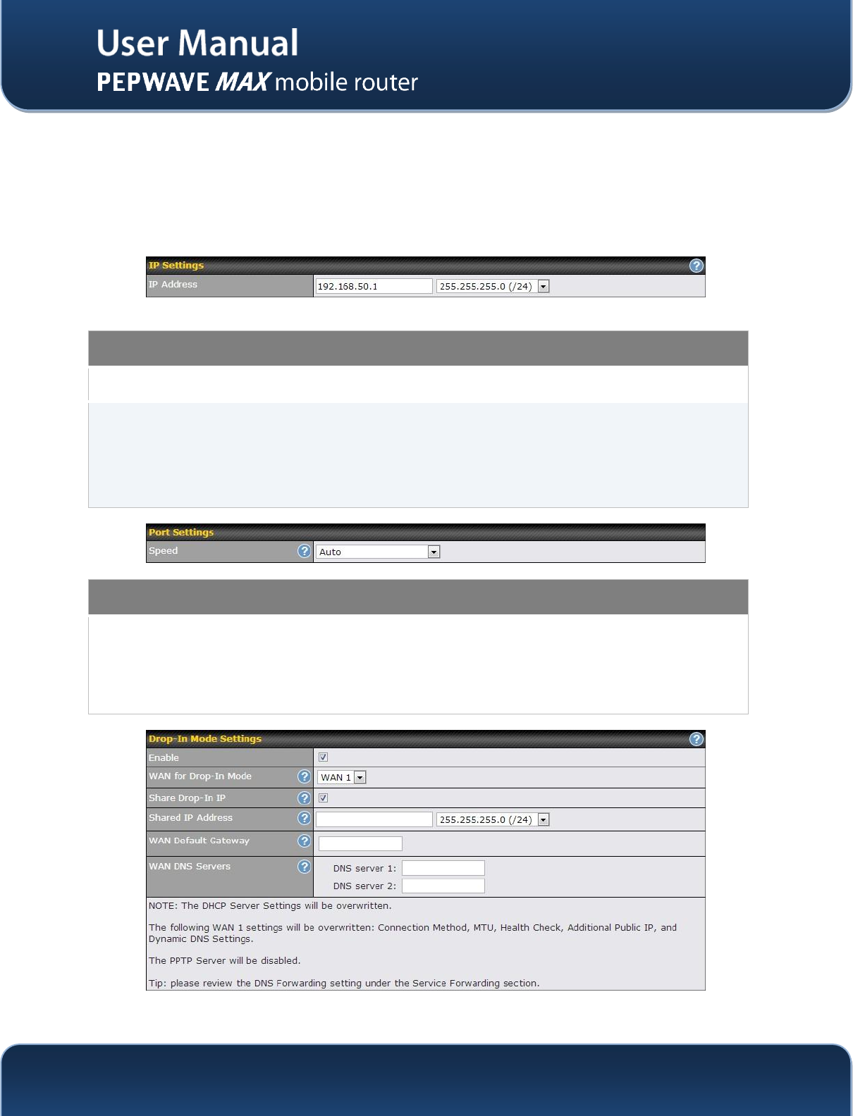
The LAN Interface settings are located in Network> LAN>Basic Settings
IP Settings
IP Address
The IP address of the Pepwave MAX on LAN.
Speed
This setting specifies the speed of the LAN Ethernet Port.
By default, Auto is selected and the appropriate data speed is automatically detected by
the Pepwave MAX.
In the event of negotiation issues, the port speed can be manually specified to circumvent
the issues. You can also choose whether or not to advertise the speed to the peer by
selecting the Advertise Speed checkbox.
Port Settings
Speed
This is the port speed of the LAN interface. It should be set to the same speed as the
connected device to avoid any port negotiation problem.
When a static speed is set, you may choose whether to advertise its speed to the peer
device or not. Advertise Speed is selected by default. You can choose not to advertise the
port speed if the port has difficulty in negotiating with the peer device.
http://www.pepwave.com
29
Copyright @ 2014 Pepwave
Drop-in Mode Settings
Enable
Drop-in Mode eases the installation of the Peplink MAX on a live network between the
existing firewall and router, such that no configuration changes are required on existing
equipment. Check the box to enable the Drop-in Mode feature.
Please refer to SectionError! Reference source not found., Error! Reference source not
found.for details.
WAN for Drop-In
Mode
Select the WAN port to be used for Drop-in Mode. If WAN 1 with LAN Bypass is selected,
the High Availability feature will be disabled automatically.
Shared Drop-In
ModeA
When this option is enabled, the passthrough IP address will be used to connect to WAN
hosts (email notification, remote syslog, etc.). The MAX Router will listen for this IP address
when WAN hosts access services provided by the MAX Router (Web Admin access from
the WAN, DNS server requests, etc.).
To connect to hosts on the LAN (email notification, remote syslog, etc.), the default gateway
address will be used. The MAX Router will listen for this IP address when LAN hosts
access services provided by the MAX Router (Web Admin access from the WAN, DNS
proxy, etc.).
Shared IP
AddressA
Access to this IP address will be passed through to the LAN port if this device is not serving
the service being accessed. The shared IP Address will be used in connecting to hosts on
the WAN (e.g. email notification, remote syslog, etc.) The device will also listen on the IP
address when hosts on the WAN access services served on this device (e.g. web admin
accesses from WAN, DNS server, etc.)
WAN Default
Gateway
Enter the WAN router's IP address in this field. If there are more hosts in addition to the
router on the WAN segment, check the I have other host(s) on WAN segment box and
enter the IP address of the hosts that need to access LAN devices or be accessed by
others.
WAN DNS Servers
Enter the selected WAN's corresponding DNS server IP addresses.
A - Advanced feature, please click the button on the top right hand corner to activate.
http://www.pepwave.com
30
Copyright @ 2014 Pepwave
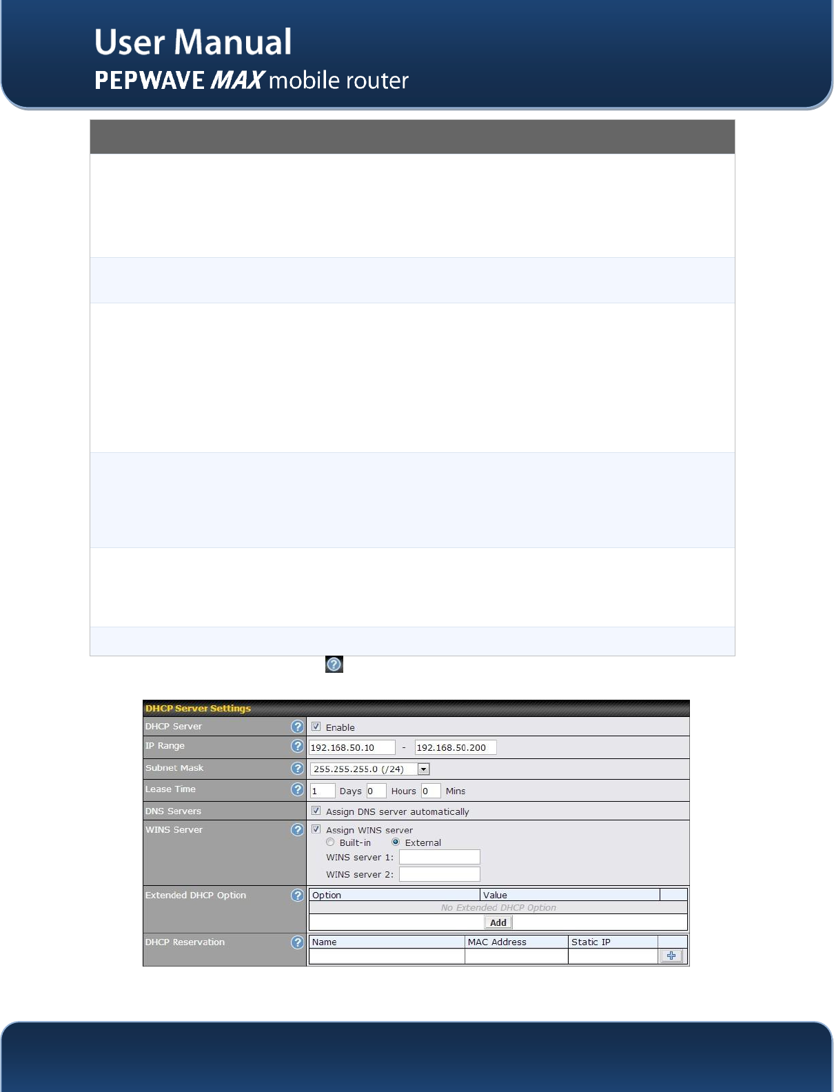
DHCP Server Settings
DHCP Server
When this setting is enabled, the DHCP server of thePepwave MAX automatically assigns
an IP address to each computer that is connected via LAN and is configured to obtain an
IP address via DHCP.
The Pepwave MAX’s DHCP server can prevent IP address collision on the LAN.
IP Range &
Subnet Mask
Thesesettings allocate a range of IP address that will be assigned to LAN computers by
the DHCP server of thePepwave MAX.
Lease Time
This setting specifies the length of time throughout which an IP address of a DHCP client
remains valid. Upon expiration of the Lease Time, the assigned IP address will no longer
be valid and the renewal of the IP address assignment will be required.
DNS Servers
This option allows you to input the DNS server addresses to be offered to the DHCP
clients. If Assign DNS server automatically is selected, the Pepwave MAX’s built-in
DNS server address (i.e. LAN IP address) will be offered.
WINS Server
This option allows you to specify the Windows Internet Name Service (WINS) server. You
may choose to use the built-in WINS server or external WINS servers.
When this unit is connected using SpeedFusionTM, other VPN peers can share this unit's
built-in WINS server by entering this unit's LAN IP address in their DHCP WINS Servers
setting. Therefore, all PC clients in the VPN can resolve the NetBIOS names of other
clients in remote peers.
If you have enabled this option, a list of WINS clients will be displayed at Status > WINS
Clients.
Extended DHCP
Option
In addition to standard DHCP options (e.g. DNS server address, gateway address, subnet
mask), you can specify the value of additional extended DHCP options, asdefined in RFC
2132. With these extended options enabled, you can pass additional configuration
information to LAN hosts.
To define an extended DHCP option, click the Add button, choose the option that you want
to define and enter its value. For values that are in IP address list format, you can enter
one IP address per line in the provided text area input control. Each option is allowed to be
defined once only.
DHCP
Reservation
This setting reserves the assignment of fixed IP addresses for a list of computers on the
LAN. The computers to be assigned fixed IP addresses on the LAN are identified by their
MAC addresses.
The fixed IP address assignment is displayed as a cross-reference list between the
computers’ names, MAC addresses and fixed IP addresses.
Name (an optional field) allows you to specifya name to represent the device. MAC
addresses should be in the format of 00:AA:BB:CC:DD:EE
Press to create a new record. Press to remove a record
Reserved clients information can be imported from the Client List, located at Status >
Client List. For more details, please refer to section 21.3.
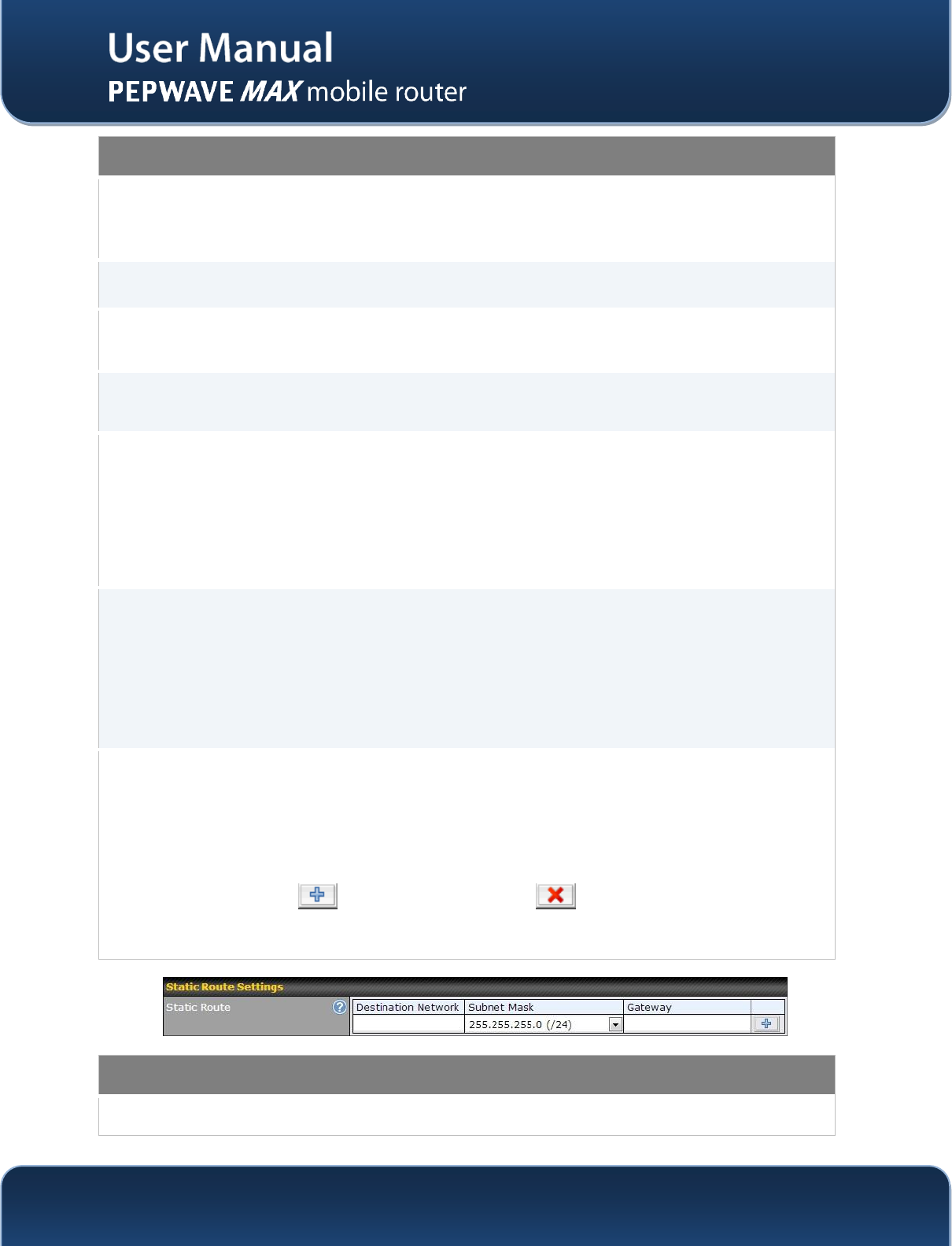
Static Route Settings
Static Route
This table is for defining static routing rules for the LAN segment. A static route consists of
the network address, subnet mask, and gateway address. The address and subnet mask
http://www.pepwave.com
31
Copyright @ 2014 Pepwave
values are in w.x.y.zformat.
The local LAN subnet and subnets behind the LAN will be advertised to the VPN. Remote
routes sent over the VPN will also be accepted. Any VPN member will be able to route to
the local subnets.
Press to create a new route. Press to remove a route.
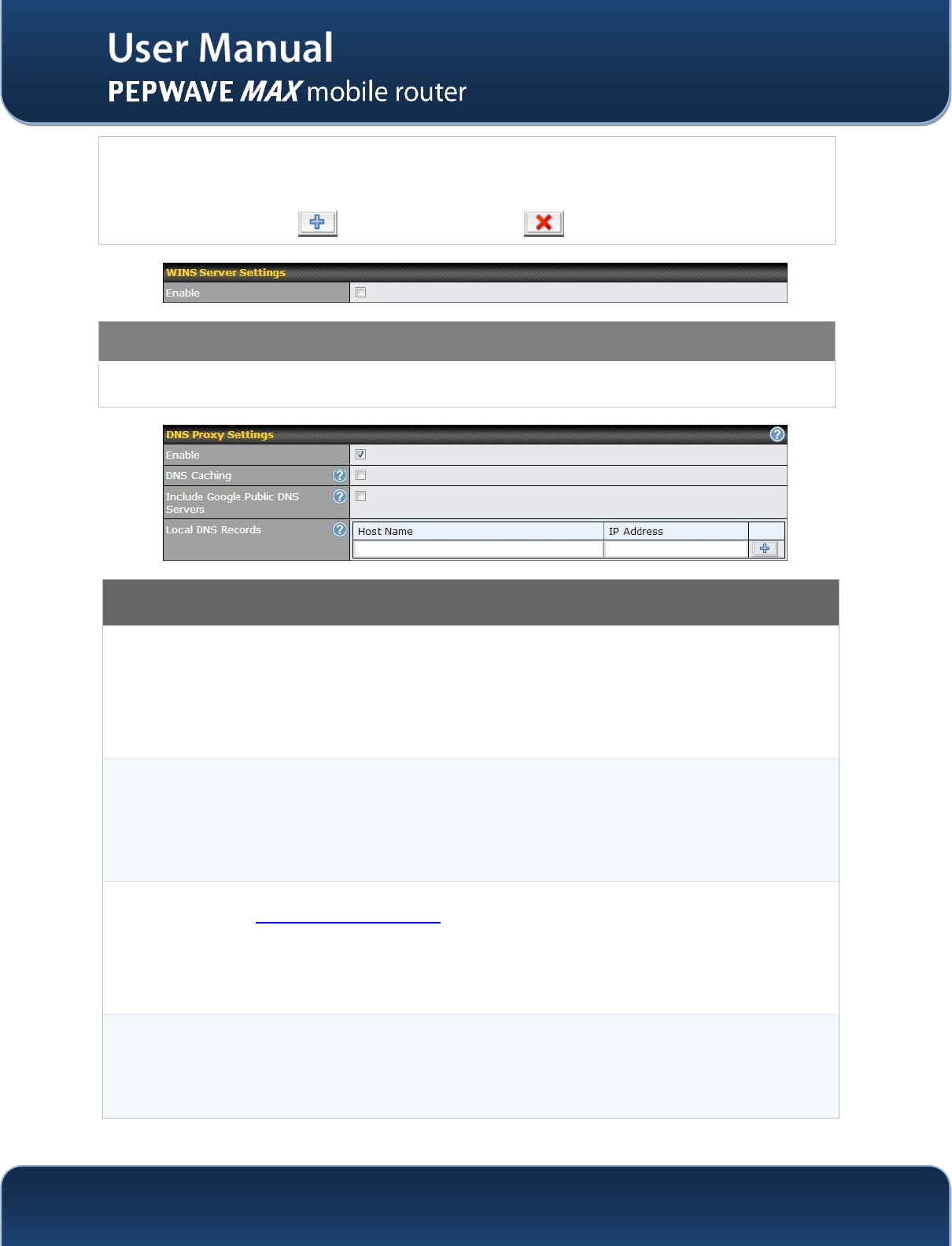
WINS Server Settings
Enable
Check the box to enable the WINS Server. A list of WINS clients will be displayed at
Status > WINS Clients.
DNS Proxy Settings
Enable
A check box to enable to DNS Proxy feature.
Network > LAN > DNS Proxy Settings table
A DNS proxy server can be enabled to serve DNS requests originating from LAN/PPTP/
SpeedFusionTMpeers. Requests are forwarded to the DNS servers/resolvers defined in
each WAN connection
DNS Caching
This field is to enable DNS caching on the built-in DNS proxy server. When the option is
enabled, queried DNS replies will be cached until the records’ TTL has been reached. This
feature can help improve the DNS lookup time. However, it cannot return the most updated
result for those frequently updated DNS records.
By default, it is disabled.
Include Google
Public DNS
Servers
When this option is enabled, the DNS proxy server will also forward DNSrequests to
Google's Public DNS Servers in addition to the DNS servers defined in each WAN. This
could increase the DNS service's availability.
Default: disabled
Local DNS
Records
This table is for defining custom local DNS records.
A static local DNS record consists of a Host Name and an IP Address. When looking up the
Host Name from the LAN to LAN IP of the Pepwave MAX, the corresponding IP Address will
be returned.
http://www.pepwave.com
32
Copyright @ 2014 Pepwave
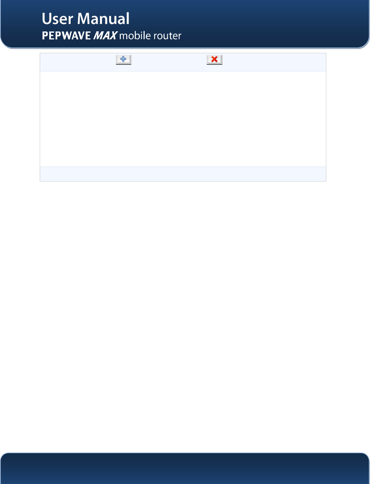
Press to create a new record. Press to remove a record.
LAN DNS
Resolver Settings
Check the box to enable the WINS Server. A list of WINS clients will be displayed at
Network > LAN > DNS Proxy Settings > DNS Resolvers.
This field specifies which DNS resolvers will receive forwarded DNS requests. If no
WAN/VPN/LAN DNS resolver is selected, all of the WAN’s DNS resolvers will be selected.
If a SpeedFusionTMpeer is selected, you may enter the VPN peer’s DNS resolver IP
address(es).
Queries will be forwarded to the selected connections’ resolvers. If all of the selected
connections are down, queries will be forwarded to all resolvers on healthy WAN
connections.
http://www.pepwave.com
33
Copyright @ 2014 Pepwave
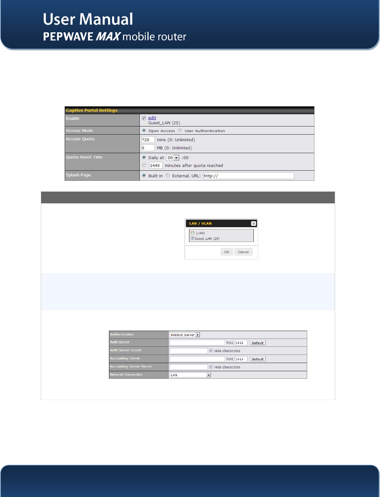
8.2 Captive Portal
The Captive Portal serves as gateway that clients have to pass if they wish to access the internet using
your router. To configure, navigate to Network >Captive Portal to see the following screen:
Captive Portal Settings
Apply On
Clicking the edit button trigger a dialogue where you can choose which LAN / VLAN to
apply your captive portal.
Click all LAN / VLAN that you wish to apply the captive portal to.
Access Mode
Click Open Access to allow clients to freely access your router. Click User
Authentication to force your clients to authenticate before accessing your router.
Radius
Server
This authenticates your clients through a Radius Server. Upon selecting this option, you
will see the following fields:
Fill in the necessary information to complete your connection to the server and enable
authentication.
http://www.pepwave.com
34
Copyright @ 2014 Pepwave
LDAP Server
This authenticates your clients through a LDAP Server. Upon selecting this option, you
will see the following fields:
Fill in the necessary information to complete your connection to the server and enable
authentication.
Access
Quota
Set a time and data cap to each user’s Internet usage.
Quota Reset
Time
This menu determines how your usage quota resets. Setting it to daily will reset it at a
specified time every day. Setting a number of minutes after quota reached establish a
timer for each user that begins after the quota has been reached.
Splash Page
Here, you can choose between using the MAX router’s built-in captive portal and
redirecting clients to a URL you define.
The Portal Customization menu has two options: and . Clicking will result in a pop-up
previewing the captive portal that your clients will see. Clicking will result in the appearance of
following menu:
http://www.pepwave.com
35
Copyright @ 2014 Pepwave
Portal Customization
Logo Image
Click the Choose File button to select an logo to use for the built-in portal
Message
If you have any additional messages for your users, place it on this field.
Terms &
Conditions
If you would like to use your own set of terms and conditions, please place it here. If left
empty, the built-in portal will display the default terms and conditions.
Custom
Landing
Page
Fill in this field to redirect clients to an external URL.
http://www.pepwave.com
36
Copyright @ 2014 Pepwave
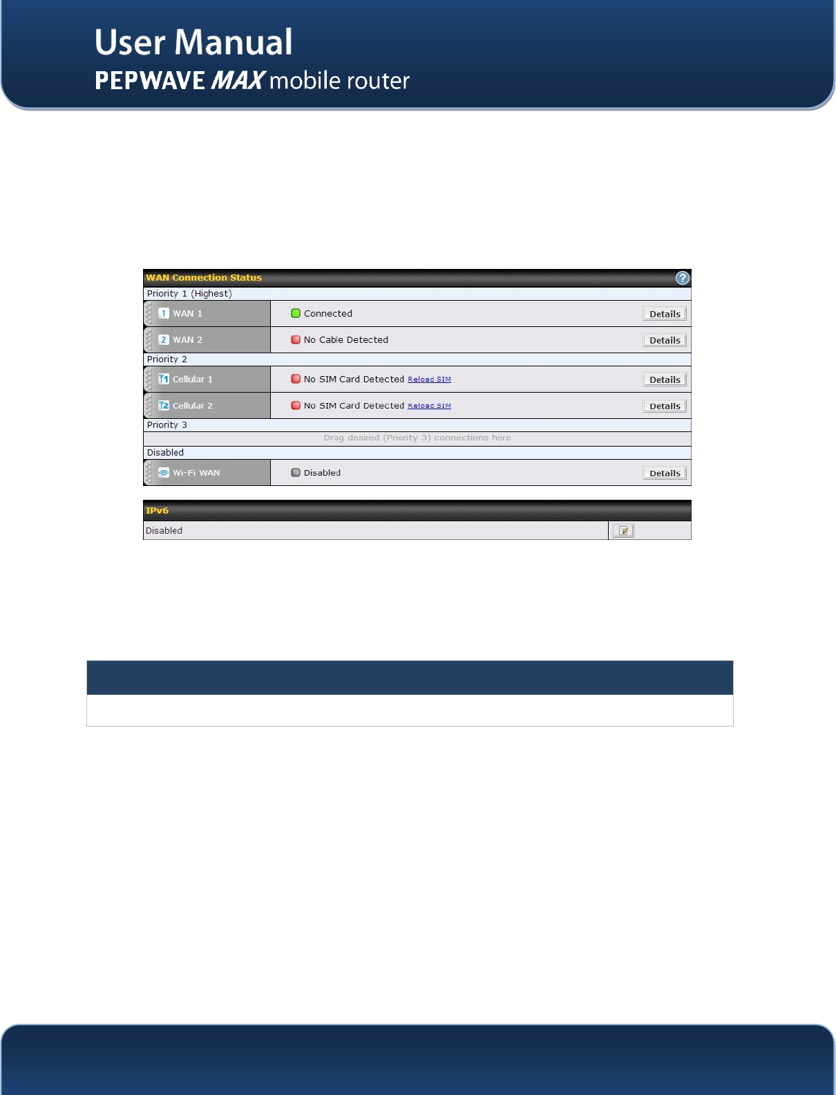
9 Configuration of WAN Interface(s)
The WAN Interface settings are located at: Network > WAN
To reorder different WANs’ priority, just drag on the appropriate WAN by holding the left mouse button,
move it to the desired priority (the first one would be the highest priority, the second one would be lower
priorityand so on) and drop it by releasing the mouse button.
To disable a particular WAN connection, just drag on the appropriate WAN by holding the left mouse
button, move it the Disabledrow and drop it by releasing the mouse button.
You can also do the above priority setting on the Dashboard, please refer to Section 0 for information.
Click the Details button in the corresponding row of connection to modify the connection setting.
Important Note
Connection Details will be changed and become effective right afterclicking the Save and Apply button.
http://www.pepwave.com
37
Copyright @ 2014 Pepwave
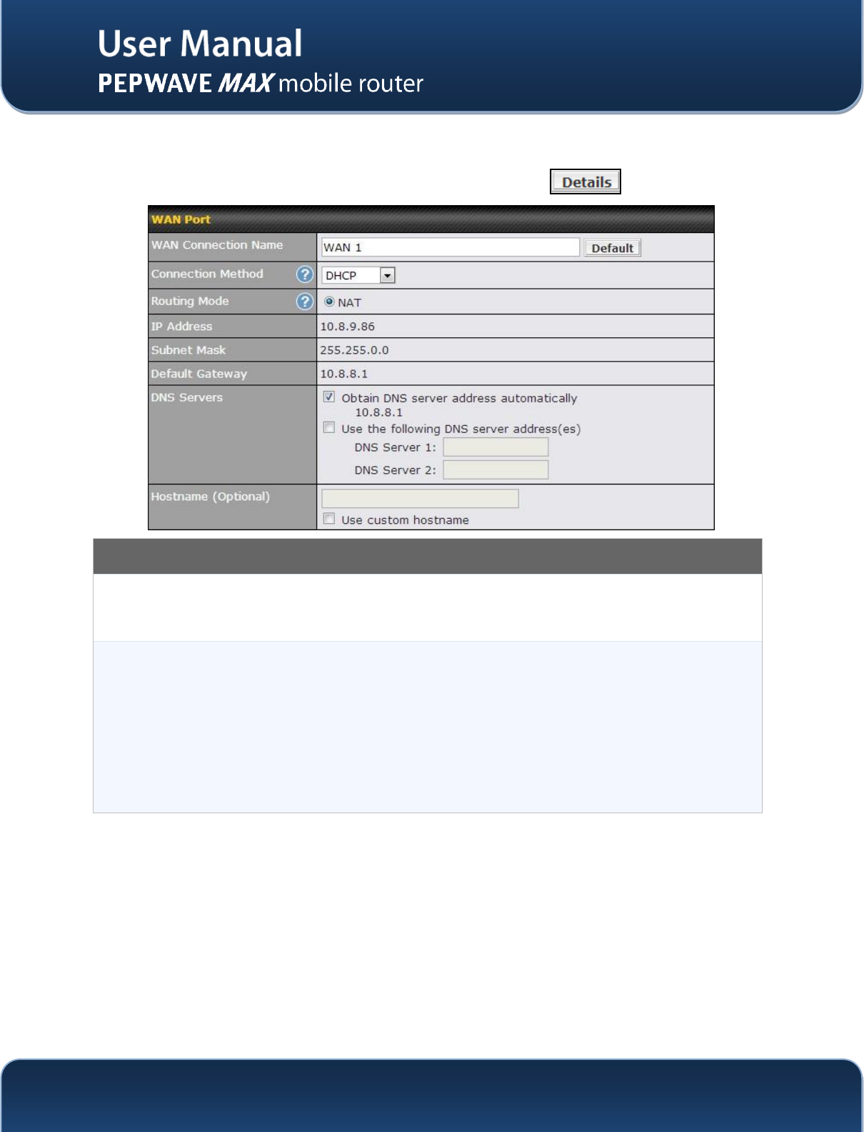
9.1 Ethernet WAN
FromNetwork > WAN, choose a WAN connection and click the button:
WAN Port –1
WAN
Connection
Name
This field is for defining a name to represent this WAN connection.
Connection
Method
There are three possible connection methods for Ethernet WAN:
DHCP
Static IP
PPPoE
The connection method and details are determined by, and can be obtained from, the ISP.
See the Sections9.1.1, 9.1.2, and 9.1.3 for details of each connection method.
http://www.pepwave.com
38
Copyright @ 2014 Pepwave
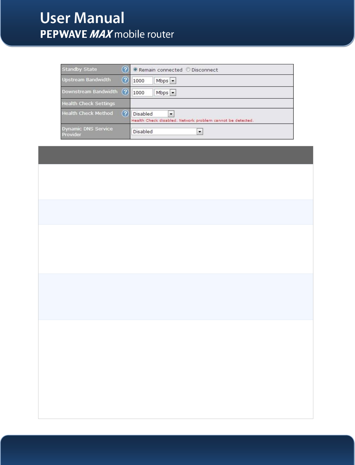
WAN Port – 2
Standby State
This setting specifies the state of the WAN connection. The available options are Remain
connected and Disconnect.
The default state is Remain Connected.
Upstream
Bandwidth
This setting specifies the data bandwidth in the outbound direction from the LAN through the
WAN interface.
Downstream
Bandwidth
This setting specifies the data bandwidth in the inbound direction from the WAN interface to the
LAN.
This value is referenced as the default weight value when using the algorithm Least Used, or the
algorithm Persistence (Auto) in Outbound Policy with Managed by Custom Rules chosen (see
Section 13.2).
Health Check
Method
This setting specifies the health check method for the WAN connection. The value of method can
be configured as Disabled, Ping or DNS Lookup.
The default method is Disabled.
See Section9.4 for configuration details.
Dynamic DNS
Service
Provider
This setting specifies the dynamic DNS service provider to be used for the WAN based on
supported dynamic DNS service providers:
changeip.com
dyndns.org
no-ip.org
tzo.com
DNS-O-Matic
Select Disabled to disable this feature.
See Section 1.1 for configuration details.
http://www.pepwave.com
39
Copyright @ 2014 Pepwave
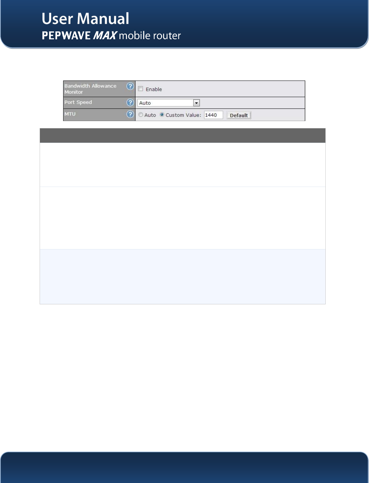
WAN Port – 3
Bandwidth
Allowance
Monitor
This option allows you to enable bandwidth usage monitoring on this WAN connection for each
billing cycle. When this is not enabled, bandwidth usage of each month is still being tracked but
no action will be taken.
See Section 9.5 for configuration details. (Action, Start Day, Monthly Allowance)
Port Speed
This setting specifies port speed and duplex configurations of the WAN Port.
By default, Auto is selected and the appropriate data speed is automatically detected by the
Pepwave MAX.
In the event of negotiation issues, the port speed can be manually specified to circumvent the
issues. You can also choose whether or not to advertise the speed to the peer by selecting the
Advertise Speed checkbox.
MTU
This setting specifies the Maximum Transmission Unit.
By default, MTU is set to Custom 1440.
You may adjust the MTU value by editing the text field. Click Default to restore the default MTU
value. Select Auto and the appropriate MTU value will be automatically detected. The auto-
detection will run each time when the WAN connection establishes.
http://www.pepwave.com
40
Copyright @ 2014 Pepwave
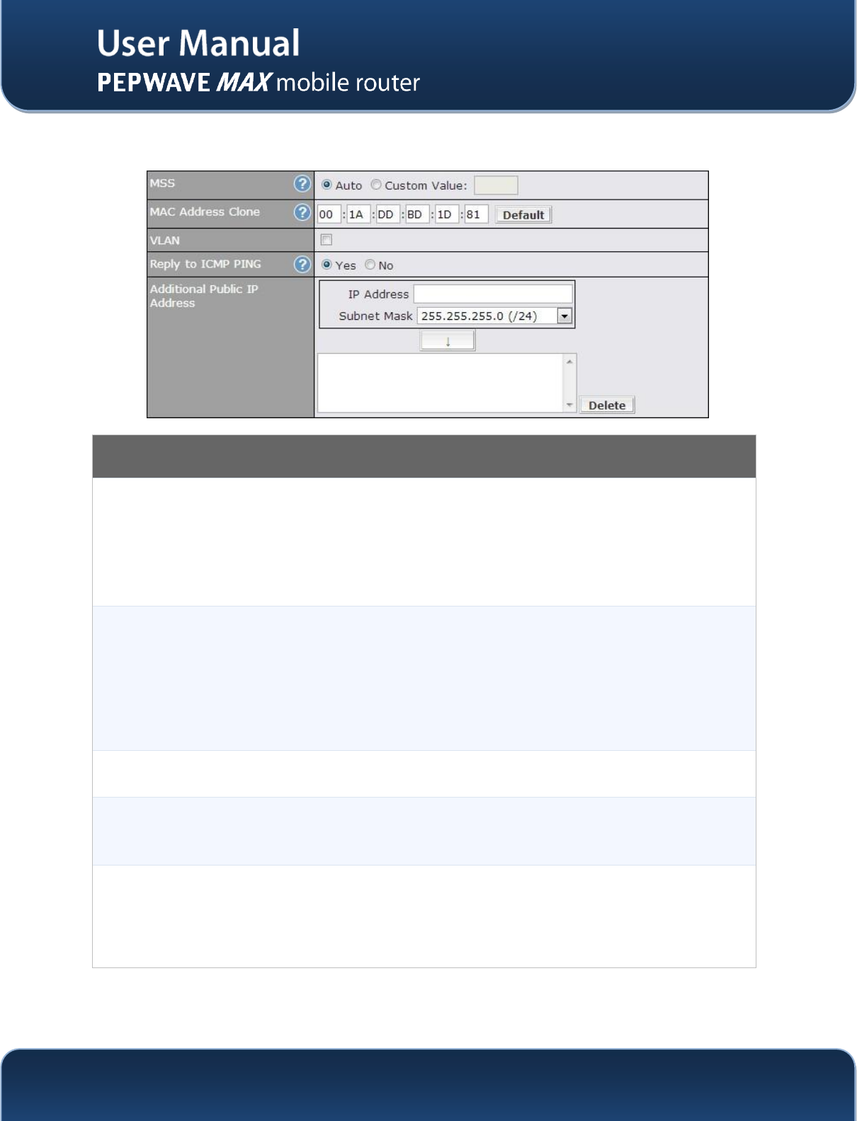
WAN Port – 5
MSS
This setting should be configured based on the maximum payload size that the local system can
handle. The MSS (Maximum Segment Size) is computed from the MTU minus 40 bytes for TCP
over IPv4.
If MTU is set to Auto, the MSS will also be set automatically.
By default, MSS is set to Auto.
MAC Address
Clone
This setting allows you to configure the MAC address.
Some service providers (e.g. cable providers) identify the client’s MAC address and require the
client to always use the same MAC address to connect to the network. In such cases, change
the WAN interface’s MAC address to the original client PC’s one via this field.
The default MAC Address is a unique value assigned at the factory. In most cases, the default
value is sufficient. Clicking the Default button restores the MAC Address to the default value.
VLAN
Click the square if you wish to enable VLAN functionality and enable multiple broadcast domains.
Once you enable VLAN, you will be able to enter a name for your network.
Reply to ICMP
PING
If this field is disabled, the WAN connection will not respond to ICMP PING requests.
By default, this is enabled.
Additional
Public IP
Address
The IP Address List represents the list of fixed Internet IP addresses assigned by the ISP, in the
event that more than one Internet IP addresses are assigned to this WAN connection.
Enter the fixed Internet IP addresses and the corresponding subnet mask, and then click the
Down Arrow button to populate IP address entries to the IP Address List.
http://www.pepwave.com
41
Copyright @ 2014 Pepwave
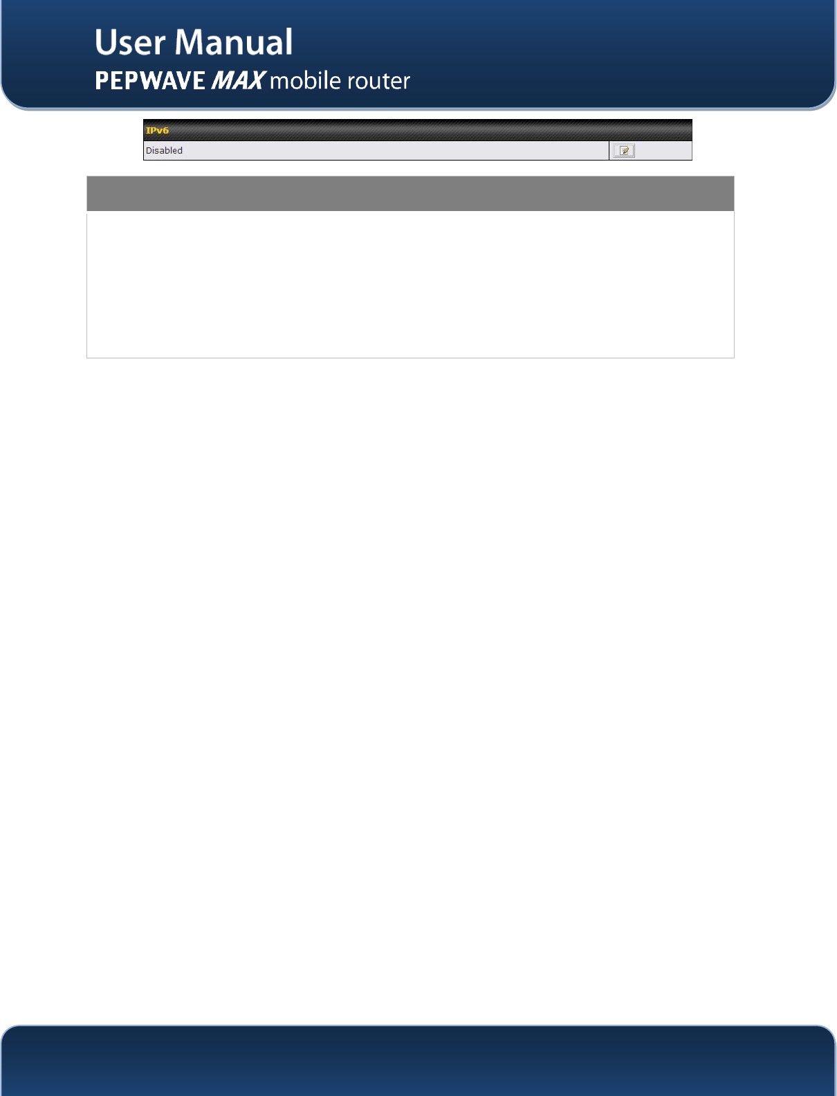
IPv6
IPv6
IPv6 support can be enabled on one of the available Ethernet WAN ports. On this screen, you
can choose which WAN will support IPv6.
To enable IPv6 support on a WAN, the WAN router must respond to Stateless Address Auto
configuration advertisements and DHCPv6 requests. IPv6 clients on the LAN will acquire their
IPv6, gateway, and DNS server addresses from it. The device will also acquire an IPv6
address for performing ping/traceroute checks and accepting web admin accesses.
Note: This feature is only available on the Pepwave MAX 700,HD2 and HD2 IP67.
http://www.pepwave.com
42
Copyright @ 2014 Pepwave
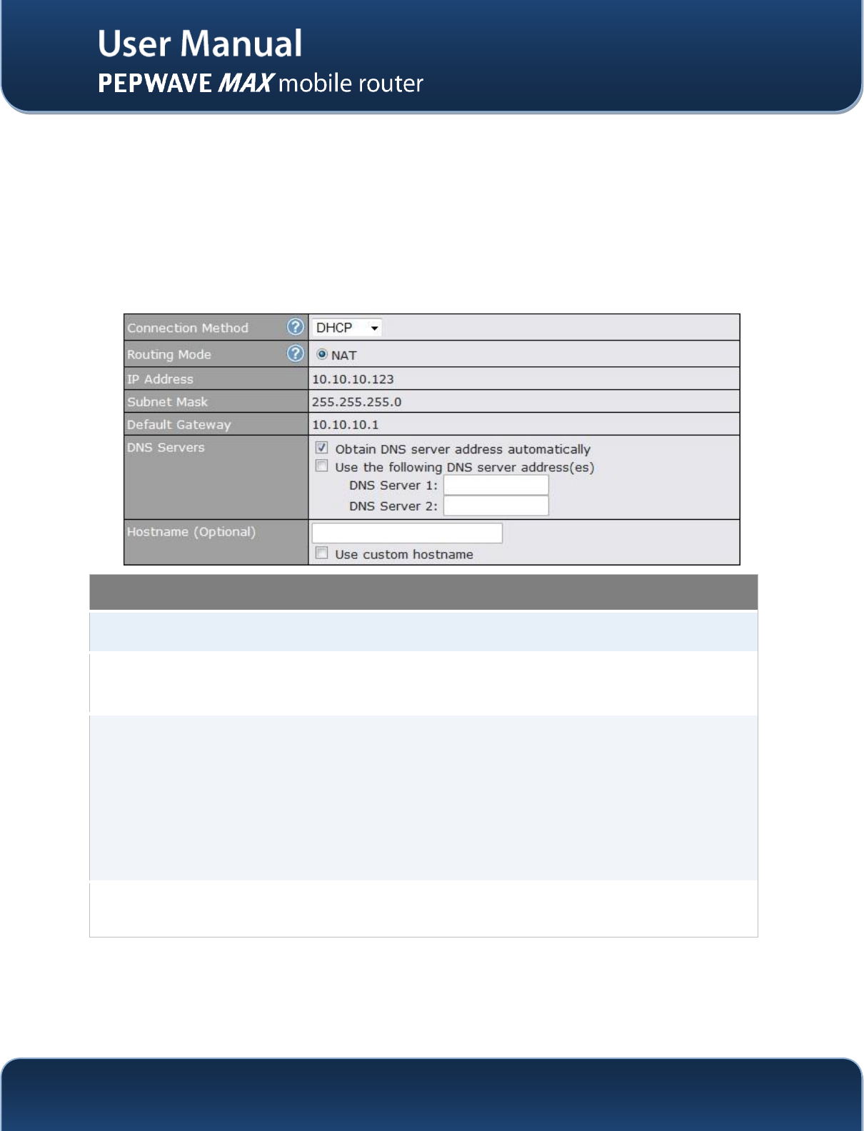
9.1.1 DHCP Connection
The DHCP connection method is suitable if the ISP provides an IP address automatically by DHCP (e.g.
Satellite Modem, WiMAX Modem, Cable, Metro Ethernet, etc.).
There are three possible connection methods:
1. DHCP
2. Static IP
3. PPPoE
DHCP Settings
Routing Mode
This is to substitute the real address in a packet with a mapped address that is
routable on the destination network
IP Address/
Subnet Mask/
Default Gateway
This information is obtained from the ISP automatically.
DNS Servers
Each ISP may provide a set of DNS servers for DNS lookups. This setting specifies the
DNS (Domain Name System) Servers to be used when a DNS lookup is routed
through this connection.
Selecting Obtain DNS server address automatically results in the DNS Servers to
be assigned by the WAN DHCP Server to be used for outbound DNS lookups over the
connection. (The DNS Servers are obtained along with the WAN IP address assigned
from the DHCP server.)
When Use the following DNS server address(es) is selected, you may enter custom
DNS server addresses for this WAN connection into the DNS Server 1 and DNS
Server 2 fields.
Hostname
(Optional)
If your service provider's DHCP server requires you to supply a hostname value upon
acquiring an IP address, you may enter the value here. If your service provider does
not provide you with the value, you can safely bypass this option.
http://www.pepwave.com
43
Copyright @ 2014 Pepwave
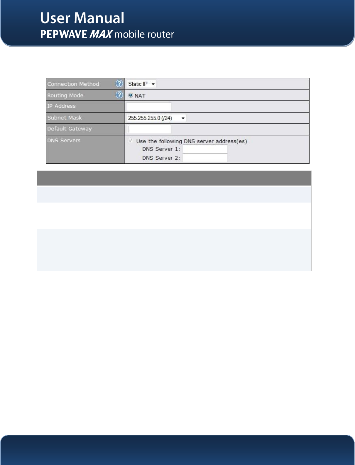
9.1.2 Static IPConnection
This Static IP connection method is suitable if ISP provides a static IP address to connect directly.
Static IP Settings
Routing Mode
This is to substitute the real address in a packet with a mapped address that is
routable on the destination network
IP Address /
Subnet Mask /
Default Gateway
These settings allow you to specify the information required in order to
communicate on the Internet via a fixed Internet IP address.
The information is typically determined by and can be obtained from the ISP.
DNS Servers
Each ISP may provide a set of DNS servers for DNS lookups. This field specifies
the DNS (Domain Name System) Servers to be used when a DNS lookup is
routed through this connection.
You can input the ISP provided DNS server addresses into the DNS Server 1
and DNS Server 2 fields. If no address is entered here, this link will not be used
for DNS lookups.
http://www.pepwave.com
44
Copyright @ 2014 Pepwave
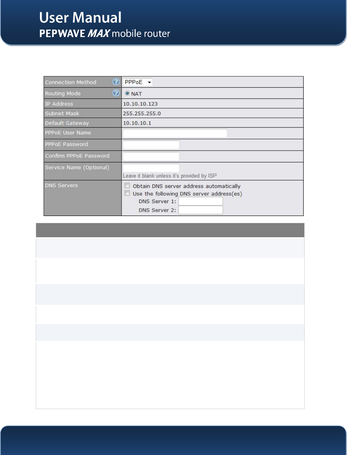
9.1.3 PPPoE Connection
This connection method is suitable if ISP provides login ID/ password to connect via PPPoE.
PPPoE Settings
Routing Mode
This is to substitute the real address in a packet with a mapped address that is
routable on the destination network
IP Address / Subnet
Mask / Default
Gateway
This information is obtained from the ISP automatically.
PPPoE User Name /
Password
Enter the required information in these fields in order to connect via PPPoE to the ISP.
The parameter values are determined by and can be obtained from the ISP.
Confirm PPPoE
Password
Verify your password by entering it again in this field.
Service Name
Service Name is provided by the ISP.
Note: Leave this field blank unless it is provided by your ISP.
DNS Servers
Each ISP may provide a set of DNS servers for DNS lookups.This setting specifies the
DNS (Domain Name System) Servers to be used when a DNS lookup is routed
through this connection.
Selecting Obtain DNS server address automatically results in the DNS Servers
assigned by the PPPoE server to be used for outbound DNS lookups over the WAN
connection. (The DNS Servers are obtained along with the WAN IP address assigned
from the PPPoE server.)
When Use the following DNS server address(es) is selected, you can put custom
DNS server addresses for this WAN connection into the DNS Server 1 and DNS
Server 2 fields.
http://www.pepwave.com
45
Copyright @ 2014 Pepwave
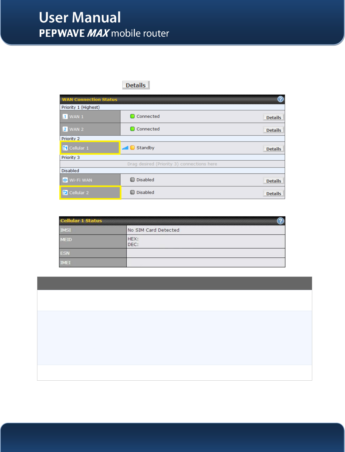
9.2 Cellular WAN
Network>WAN> Click on Detail
(Available on the Pepwave BR1, MAX HD2, and HD2 IP67 only)
Cellular Status
IMSI
This is the International Mobile Subscriber Identity which uniquely identifies the SIM card.
This is applicable to 3G modems only.
MEID
The Pepwave MAX supports both HSPA and EV-DO.
For Sprint or Verizon Wireless EV-DO users, a unique MEID identifier code (in
hexadecimal format) is used by the carrier to associate the EV-DO device with the user.
This information is presented in hex and decimal format.
ESN
This serves the same purpose as MEID HEX but uses an older format.
IMEI
This is the unique ID for identifying the modem in GSM/HSPA mode.
http://www.pepwave.com
46
Copyright @ 2014 Pepwave
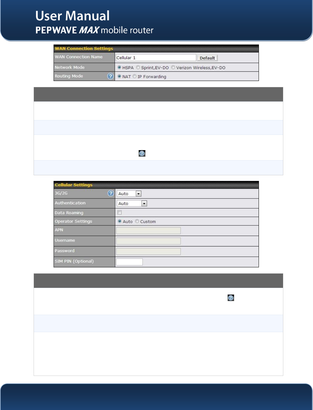
WAN Connection Settings
WAN Connection
Name
This field is for defining a name to represent this WAN connection.
Network Mode
Users have to specify the Network they are on accordingly.
Routing Mode
This option allows you to select the routing method to be used in routing IP frames via the
WAN connection. The mode can be either NAT (Network Address Translation) or IP
Forwarding. Click the button to enable IP Forwarding.
Cellular Settings
3G/2G
Band selection to restrict cellular on particular band. Click on the button to enable the
selection of specific bands.
Data Roaming
This checkbox enables data roaming on this particular SIM card. Please check your
service provider’s data roaming policy before proceeding.
Operator Settings
This setting applies to 3G / EDGE / GPRS modem only. It does not apply to EVDO / EVDO
Rev. A modem.
This allows you to configure the APN settings of your connection. If Auto is selected, the
mobile operator should be detected automatically. The connected device will be
configured and connection will be made automatically afterwards. If there is any difficulty
in making connection, you may select Custom to enter your carrier’s APN, Login,
http://www.pepwave.com
47
Copyright @ 2014 Pepwave
Password, and Dial Number settings manually. The correct values can be obtained from
your carrier.
The default and recommended Operator Settings is Auto.
APN / Login /
Password / SIM
PIN
When Auto is selected, the information in these fields will be filled automatically.
Select the option Custom and you may customize these parameters. The parameters
values are determined by and can be obtained from the ISP.
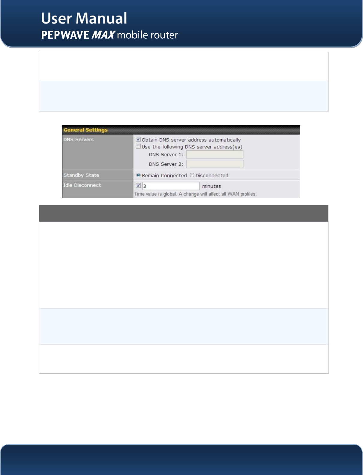
General Settings
DNS Servers
Each ISP may provide a set of DNS servers for DNS lookups.This setting specifies the
DNS (Domain Name System) Servers to be used when a DNS lookup is routed through
this connection.
Selecting Obtain DNS server address automatically results in the DNS Servers
assigned by the PPPoE server to be used for outbound DNS lookups over the WAN
connection. (The DNS Servers are obtained along with the WAN IP address assigned
from the PPPoE server.)
When Use the following DNS server address(es) is selected, you can put custom DNS
server addresses for this WAN connection into the DNS Server 1 and DNS Server 2
fields.
Standby State
This option allows you to choose whether to remain the connection connected or
disconnected when this WAN connection is no longer in the highest priority and has
entered the standby state. When Remain connected is chosen, upon bringing up this
WAN connection to active, it will be immediately available for use.
Idle Disconnect
When Internet traffic is not detected within the user specified timeframe, the modem will
automatically disconnect. Once the traffic is resumed by the LAN host, the connection
will be re-activated,
http://www.pepwave.com
48
Copyright @ 2014 Pepwave
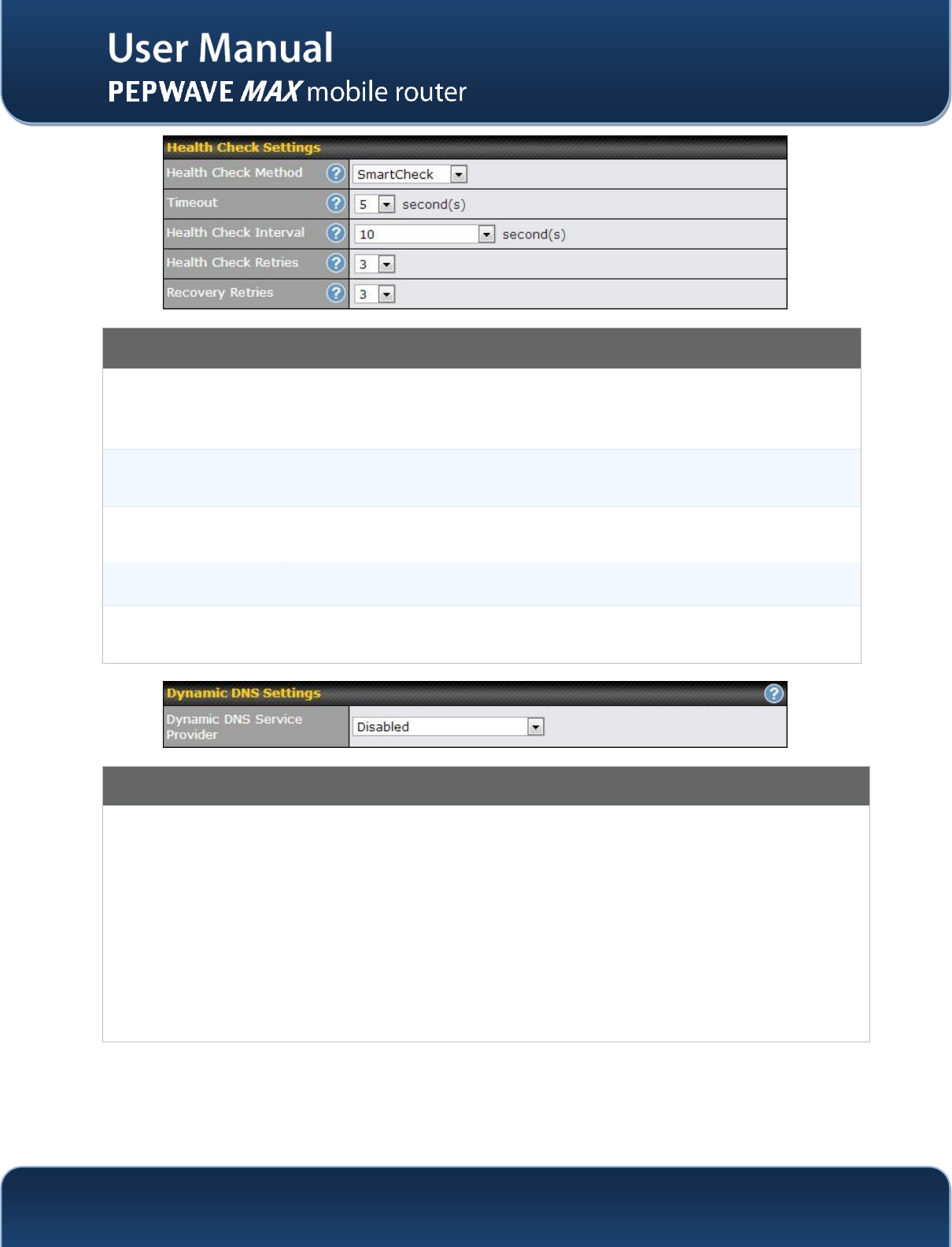
Health Check Settings
Heath Check
Method
This setting allows you to specify the health check method for the Cellular connection.
The as available options are Disabled, Ping, DNS Lookup, HTTP, and SmartCheck
The default method is DNS Lookup.See Section 9.4 for configuration details.
Timeout
If a health check test cannot be completed within the specified amount of time, the test
will be treated as failed.
Health Check
Interval
This is the time interval between each health check test.
Health Check Retries
This is the number of consecutive check failures before treating a connection as down.
Recovery Retries
This is the number of responses required after a health check failure before treating a
connection as up again.
Dynamic DNS Settings
Dynamic DNS Service
Provider
This setting specifies the dynamic DNS service provider to be used for the WAN based on
supported dynamic DNS service providers:
changeip.com
dyndns.org
no-ip.org
tzo.com
DNS-O-Matic
Select Disabled to disable this feature.See Section 1.1 for configuration details.
http://www.pepwave.com
49
Copyright @ 2014 Pepwave
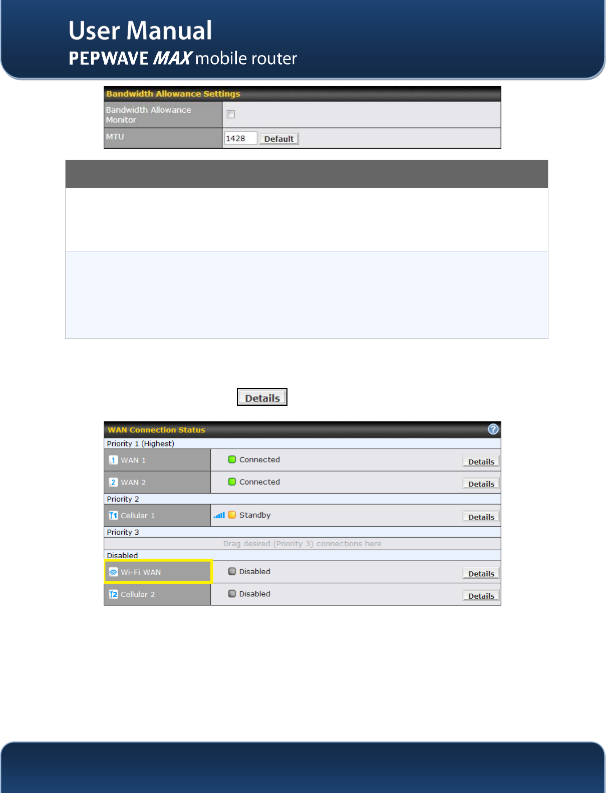
Bandwidth Allowance Settings
Bandwidth Allowance
Monitor
This option allows you to enable bandwidth usage monitoring on this WAN connection
for each billing cycle. When this is not enabled, bandwidth usage of each month is still
being tracked but no action will be taken.
See Section 9.5 for configuration details.
MTU
This setting specifies the Maximum Transmission Unit.
By default, MTU is set to Custom 1440.
You may adjust the MTU value by editing the text field. Click Default to restore the
default MTU value. Select Auto and the appropriate MTU value will be automatically
detected. The auto-detection will run each time when the WAN connection establishes
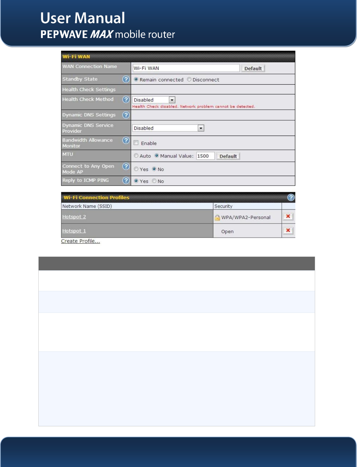
Wi-Fi WAN
Network>WAN>Click on Wi-Fi WAN
http://www.pepwave.com
50
Copyright @ 2014 Pepwave
Wi-Fi WAN Settings
WAN Connection
Name
This field is for defining a name to represent this WAN connection.
Standby State
This setting specifies the state of the WAN connection while in standby. The available
options are Remain Connected (hot standby) and Disconnect (cold standby).
Health Check
Method
This setting allows you to specify the health check method for the WAN connection. The
available options are Disabled, Ping, and DNS Lookup.
The default method is Disabled.
See Section 9.4 for configuration details.
Dynamic DNS
This setting specifies the dynamic DNS service provider to be used for the WAN based
on supported dynamic DNS service providers:
changeip.com
dyndns.org
no-ip.org
tzo.com
DNS-O-Matic
http://www.pepwave.com
51
Copyright @ 2014 Pepwave
Select Disabled to disable this feature.See Section 1.1 for configuration details.
Bandwidth
Allowance Monitor
This option allows you to enable bandwidth usage monitoring on this WAN connection
for each billing cycle. When this is not enabled, bandwidth usage of each month is still
being tracked but no action will be taken.
See Section 9.5 for configuration details.
MTU
This setting specifies the Maximum Transmission Unit.
By default, MTU is set to Custom 1440.
You may adjust the MTU value by editing the text field. Click Default to restore the
default MTU value. Select Auto and the appropriate MTU value will be automatically
detected. The auto-detection will run each time when the WAN connection establishes
Connect to Any
Open Mode AP
This option is to specify whether the Wi-Fi WAN will connect to any open mode access
point it finds. By default, this is disabled.
Reply to ICMP
PING
If this field is disabled, the WAN connection will not respond to ICMP PING requests.
By default, this is enabled.
http://www.pepwave.com
52
Copyright @ 2014 Pepwave
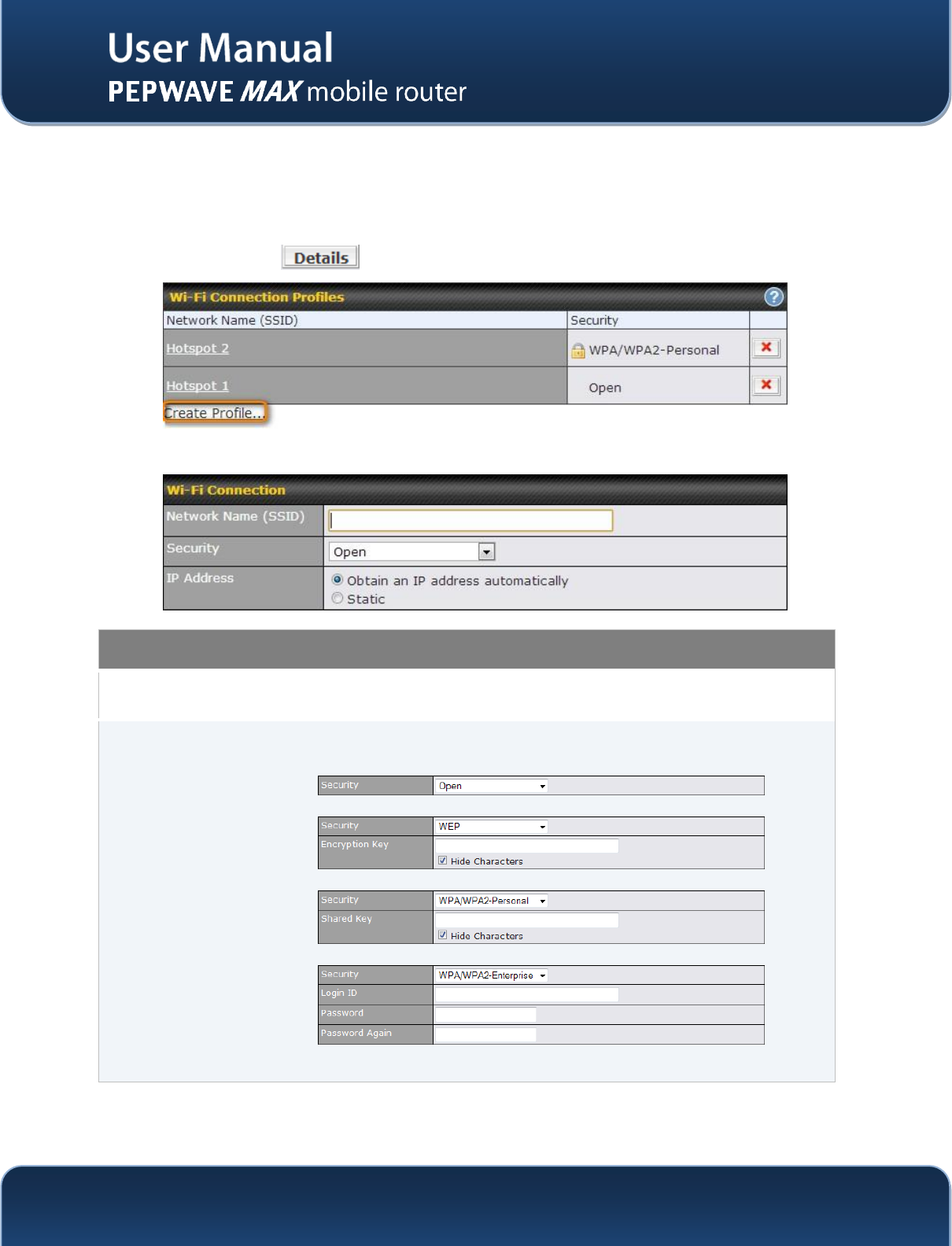
9.3.1 Create Wi-Fi Connection Profile
You can manually create a profile to connect to a Wi-Fi connection. It is useful for creating a profile for
connecting to hidden-SSID access points. Click on the link Create Profile… and the following window will
be displayed.
Network > WAN click on andthen click onCreate Profile….
This will open a window similar to the shown below
Create Wi-Fi Connection Profile Settings
Network Name
(SSID)
This field is for defining a name to represent this Wi-Fi connection.
Security
This option allows you to select which security policy is used for this wireless network.
Available options:
Open
WEP
WPA/WPA2 – Personal
WPA/WPA2 – Enterprise
The settings to be displayed under this row will vary depending on the selected security
policy.
http://www.pepwave.com
53
Copyright @ 2014 Pepwave
9.4 WAN Health Check
To ensure traffic is routed to healthy WAN connections only, the Pepwave MAX provides the functionality
to periodically check the health of each WAN connection.
The Health Check settings for each WAN connection can be independently configured via Network >
WAN > Details:
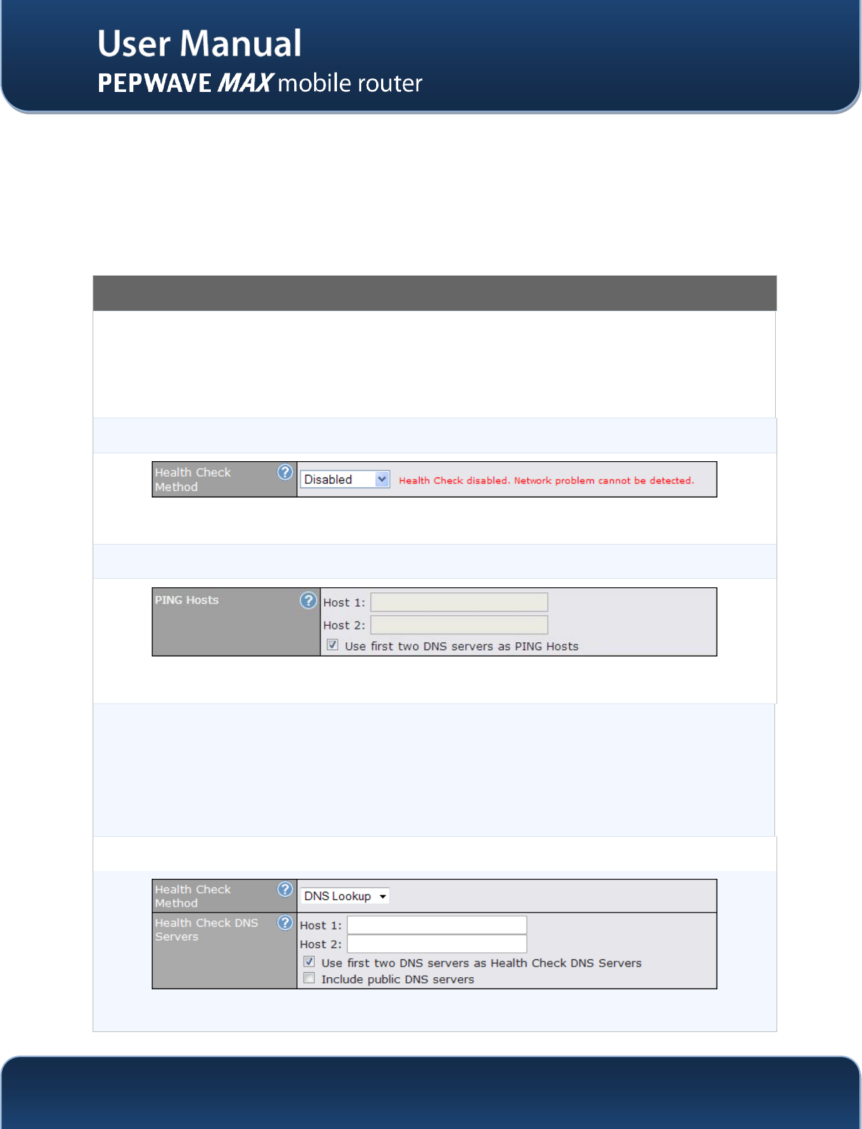
Health Check Settings
Method
This setting specifies the health check method for the WAN connection. The value of
Method can be configured as Disabled, Ping or DNS Lookup. The default method is DNS
Lookup.
For Mobile Internet connection, the value of Method can be configured as Disabled
orSmartCheck.
Health Check Disabled
When Disabledis chosen in the Method field, the WAN connection will always be considered as up. The connection
will not be treated as down in the event of IP routing errors.
Health Check Method: PING
The ICMP PING packets will be issued to test the connectivity with a configurable target IP address or host name. A
WAN connection is considered as up if PING responses are received from either one or both of the PING Hosts.
PING Hosts
This setting specifies IP addresses or host names with which connectivity is to be tested via
ICMP Ping.
If Use first two DNS servers as Ping Hostsis checked, the target PING Host will be the
first DNS server for the corresponding WAN connection.
Reliable PING hosts with a high uptime should be considered.
By default, the first two DNS servers of the WAN connection are used as the PING Hosts.
Health Check Method: DNS Lookup
DNS lookups will be issued to test the connectivity with target DNS servers. The connection will be treated as up if
DNS responses are received from either one or both of the servers, regardless of whether the result was positive or
http://www.pepwave.com
54
Copyright @ 2014 Pepwave
negative.
Health Check DNS
Servers
This field allows you to specify two DNS hosts’ IP address with which connectivity is to be
tested via DNS Lookup.
If Use first two DNS servers as Health Check DNS Serversis checked, the first two DNS
servers will be the DNS lookup targets for checking a connection's health. If the box is not
checked, field Host 1 must be filled and field Host 2 is optional.
If the box Include public DNS servers is selected and no response is received from all
specified DNS servers, DNS lookups will also be issued to some public DNS servers. A
WAN connection will be treated as down only if there is also no response received from the
public DNS servers.
Connections will be considered up if DNS responses are received from any one of the
health check DNS servers, regardless of a positive or negative result.
By default, the first two DNS servers of the WAN connection are used as the Health Check
DNS Servers.
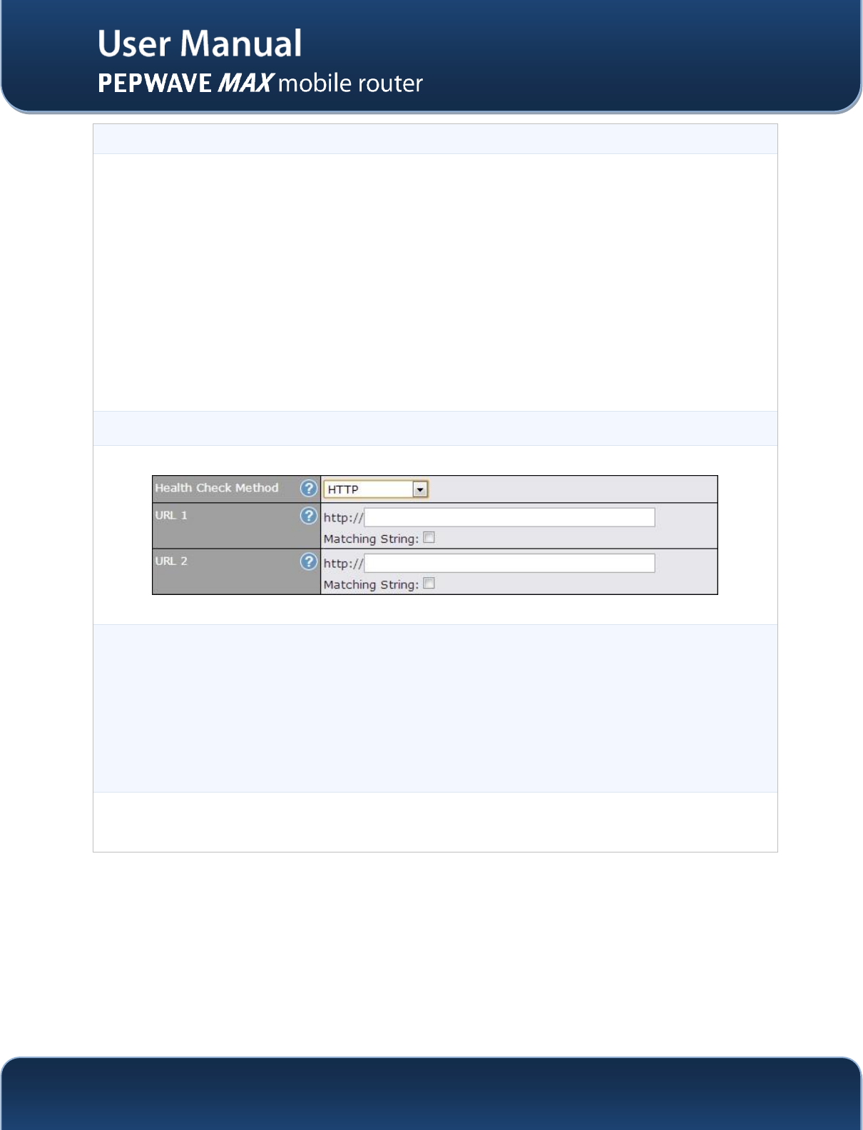
Health Check Method: HTTP
URL 1
HTTP connections will be issued to test the connectivity with configurable URLs and strings
to match.
WAN Settings > WAN Edit > Health Check Settings >URL 1
The URL will be retrieved when performing an HTTP health check. When String to Match is
left blank, a health check will pass if the HTTP return code is between 200 and 299 (Note:
HTTP redirection codes 301 or 302 are treated as failures). When String to Match is filled, a
health check will pass if the HTTP return code is between 200 and 299 and if the HTTP
response content contains the string
URL 2
WAN Settings > WAN Edit > Health Check Settings >URL 2
If URL 2 is also provided, a health check will pass if either one of the tests passed.
http://www.pepwave.com
55
Copyright @ 2014 Pepwave
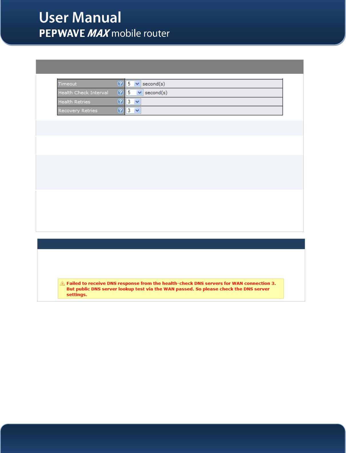
Other Health Check Settings
Timeout
This setting specifies the timeout, in seconds, for ping/DNS lookup requests. Default
Timeout is set to 5 second.
Health Check
Interval
This setting specifies the time interval, in seconds, between ping or DNS lookup requests.
Default Health Check Interval is 5 seconds.
Health Check
Retries
This setting specifies the number of consecutive ping/DNS lookup timeouts after which the
Pepwave MAX is to treat the corresponding WAN connection as down. Default Health
Retries is set to 3.
For example, with the default Health Retries setting of 3, after consecutive 3 timeouts, the
corresponding WAN connection will be treated as down.
Recovery Retries
This setting specifies the number of consecutive successful ping/DNS lookup responses
that must be received before the Pepwave MAX treats a previously down WAN connection
to be up again.
By default, Recover Times is set to 3. For example, a WAN connection that is treated as
down will be considered to be up again upon receiving 3 consecutive successful ping/DNS
lookup responses.
Automatic Public DNS Server Check on DNS Test Failure
In case the health check method is set to DNS Lookup and checks failed, the MAX will automatically perform DNS
lookups on some public DNS servers. If the tests are success, it means the WAN may not be down but rather the
target DNS server became malfunctioned. You will see the following warning message on the Main page.
http://www.pepwave.com
56
Copyright @ 2014 Pepwave
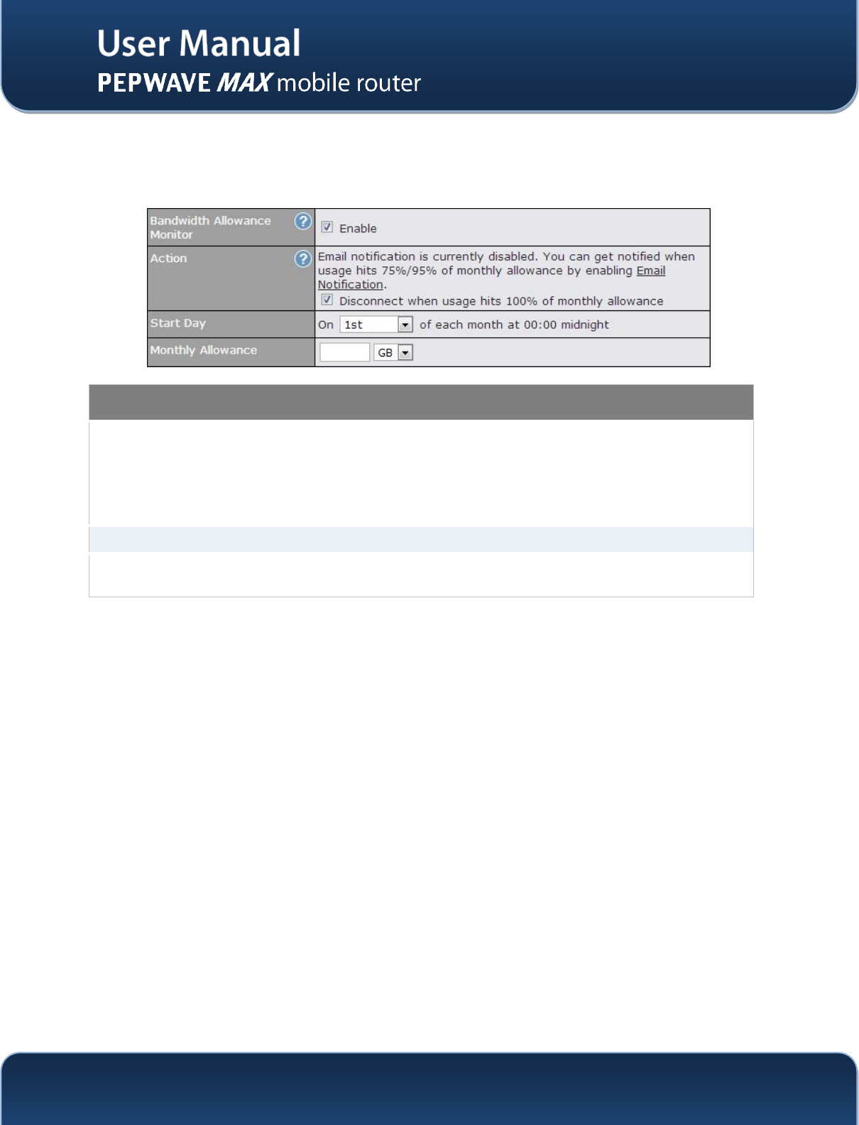
9.5 Bandwidth Allowance Monitor
Bandwidth Allowance Monitor helpskeep track of your network usage. Click Enable to begin.
Bandwidth Allowance Monitor
Action
If the feature Email Notification is enabled, you will be notified through email when
usage hits 75% and 95% of the monthly allowance.
If the box Disconnect when usage hits 100% of monthly allowance is checked, this
WAN connection will be disconnected automatically when the usage hits the monthly
allowance. It will not resume connection unless this option has been turned off or the
usage has been reset when a new billing cycle starts.
Start Day
This option allows you to define which day in the month each billing cycle begins.
Monthly
Allowance
This field is for defining the maximum bandwidth usage allowed for the WAN
connection each month.
http://www.pepwave.com
57
Copyright @ 2014 Pepwave
9.6 Dynamic DNS Settings
The Pepwave MAXis capable of registering the domain name relationships to dynamic DNS service
providers. Through registration with dynamic DNS service provider(s), the default public Internet IP
address of each WAN connection can be associated with a host name. With Dynamic DNS service
enabled for a WAN connection, you can connect to your WAN's IP address from the external even if its IP
address is dynamic. You have to register for an account from the listed dynamic DNS service providers
before enabling this option.
If the WAN connection's IP address is a reserved private IP address (i.e. behind a NAT router), the Public
IP of each WAN will be automatically reported to the DNS service provider.
Either upon a change in IP addresses or every 23 days without link reconnection, the Pepwave MAX will
connect to the dynamic DNS service provider to perform an IP address update within the provider’s
records.
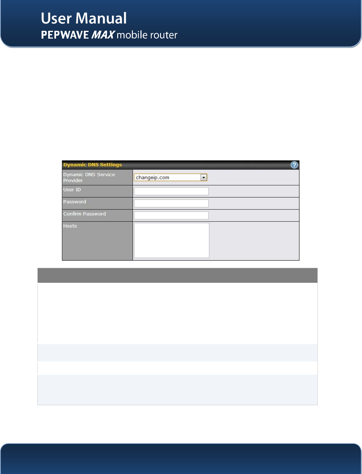
Dynamic DNS Settings
Dynamic DNS
This setting specifies the dynamic DNS service provider to be used for the WAN based
on supported dynamic DNS service providers:
changeip.com
dyndns.org
no-ip.org
tzo.com
DNS-O-Matic
Select Disabled to disable this feature.
Account Name /
Email Address
This setting specifies the registered user name for the dynamic DNS service.
Password / TZO Key
This setting specifies the password for the dynamic DNS service.
Hosts / Domain
This field allows you to specify a list of host names or domains to be associated with
the public Internet IP address of the WAN connection.
If you need to enter more than one host, you can use a carriage return to separate
them.
http://www.pepwave.com
58
Copyright @ 2014 Pepwave
Important Note
In order to use dynamic DNS services, appropriate host name registration(s) as well as a valid account with a
supported dynamic DNS service provider are required.
A dynamic DNS update is performed whenever a WAN’s IP address changes. E.g. IP is changed after a DHCP IP
refresh, reconnection, etc.
Due to dynamic DNS service providers’ policy; a dynamic DNS host will automatically expire if the host record has
not been updated for a long time. Therefore the Pepwave MAX performs an update every 23 days even if a WAN’s
IP address has not changed.
http://www.pepwave.com
59
Copyright @ 2014 Pepwave
10 Advanced Wi-Fi Settings
Wi-Fi settings can be configured at Advanced> Wi-Fi Settings. Please note that menus displayed will
vary with model.
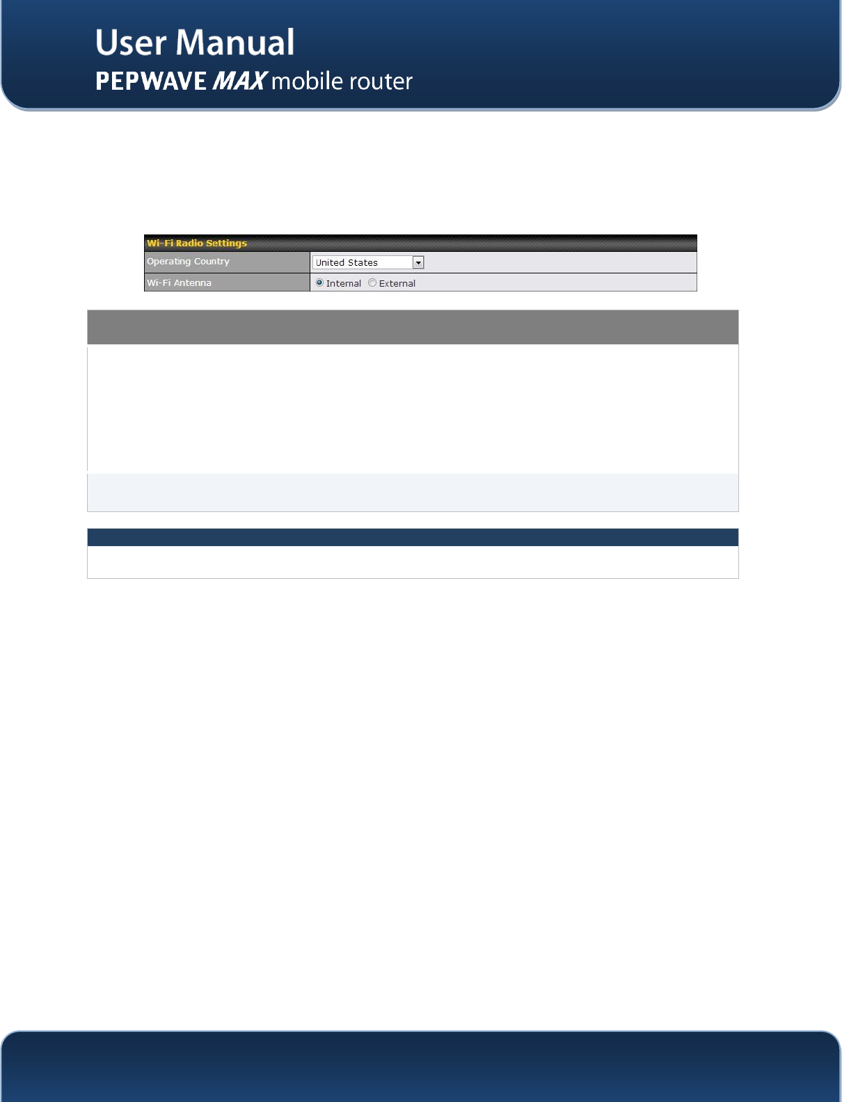
Wi-Fi Radio Settings
Operating Country
This drop-down menu specifies the national / regional regulations which the Wi-Fi
Radio should follow.
If a North American region is selected, RF channels 1 to 11 will be available
and the maximum transmission power will be 26 dBm (400 mW).
If European region is selected, RF channels 1 to 13 will be available. The
maximum transmission power will be 20 dBm (100 mW).
NOTE: Users are required to choose an option suitable to local laws and regulations.
Wi-Fi Antenna
This setting determines whether the Wi-Fi radio will use its internal antenna, or rely on
an outside one installed on its SMA or Type-N connectors.
Important Note
Per FCC regulation, the country selection is not available on all models marketed in US. All US models
are fixed to US channel only.
http://www.pepwave.com
60
Copyright @ 2014 Pepwave
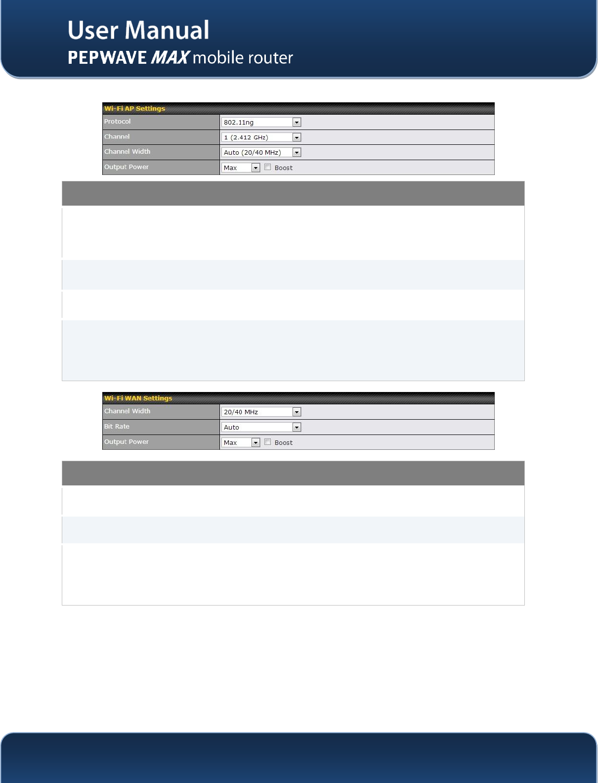
Wi-Fi AP Settings
Protocol
This option allows you to specify whether 802.11b and/or 802.11g client association
requests will be accepted. Available options are 802.11b/g,802.11b Only, and
802.11g Only.
By default, 802.11b/g is selected.
Channel
This option allows you to select which 802.11 RF channel will be utilized.
Channel 1 (2.412 GHz) is selected by default.
Channel Width
Options Auto (20/40 MHz) and 20 MHz are available. Default is Auto (20/40 MHz),
which allows both widths to be used simultaneously.
Output Power
This option is for specifying the transmission output power for the Wi-Fi AP.
There are 4 relative power levels available – Max, High, Mid and Low. The actual
output power will be bound by the regulatory limits of the selected country. By default,
23 dBm (200 mW) or 20 dBm (100 mW) (depending on which operating country you
have chosen in the previous section) is selected.
Wi-Fi WAN Settings
Channel Width
Options Auto (20/40 MHz) and 20 MHz are available. Default is Auto (20/40 MHz),
which allows both widths to be used simultaneously.
Bit Rate
This option allows you to select a specific bit rate for data transfer over the device’s Wi-
Fi network. By default, Auto is selected.
Output Power
This option is for specifying the transmission output power for the Wi-Fi AP.
There are 4 relative power levels available – Max, High, Mid and Low. The actual
output power will be bound by the regulatory limits of the selected country. By default,
23 dBm (200 mW) or 20 dBm (100 mW) (depending on which operating country you
have chosen in the previous section) is selected.
http://www.pepwave.com
61
Copyright @ 2014 Pepwave
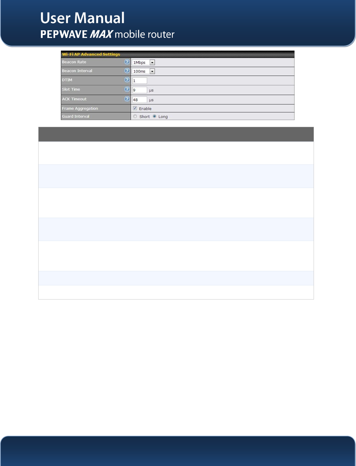
Wi-Fi AP Advanced Settings
Beacon Rate
This option is for setting the transmit bit rate for sending a beacon.
By default, 1Mbps is selected.
Beacon Interval
This option is for setting the time interval between each beacon.
By default, 100ms is selected.
DTIM
This field allows you to set the frequency for the beacon to include Delivery Traffic
Indication Message. The interval is measured in millisecond.
The default value is set to 1 ms.
Slot Time
This field is for specifying the unit wait time before it transmits a packet.
By default, this field is set to 9 µs.
ACK Timeout
This field is for setting the wait time to receive an acknowledgement packet before
performing a retransmission.
By default, this field is set to 48 µs.
Frame Aggregation
This option allows you to enable frame aggregation to increase transmission throughput.
Guard Interval
This is where you opt for a short or long guard period interval for your transmissions.
http://www.pepwave.com
62
Copyright @ 2014 Pepwave
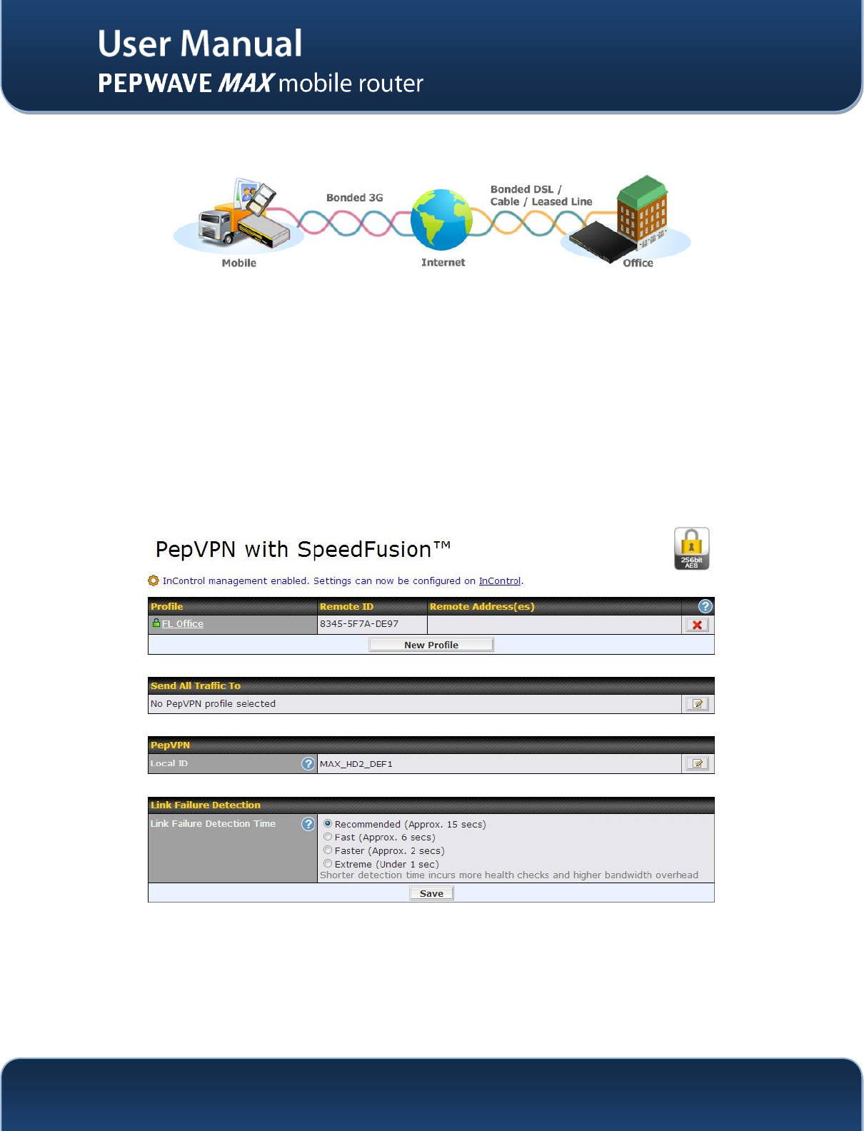
11 Bandwidth Bonding SpeedFusionTM
The Pepwave Bandwidth Bonding SpeedFusionTMfunctionality securely connectsyourMAX router to
anotherPepwave MAX or Peplink device (only Peplink Balance 210/310/380/580/710/1350 are available
for this function). The data, voice, or video communications between these locations are kept confidential
across the public Internet.
The Bandwidth Bonding SpeedFusionTM of the Pepwave MAX is specifically designed for multi-WAN
environment. The Pepwave MAX can aggregate all WAN connections’ bandwidth for routing
SpeedFusionTMtraffic. Unless all the WAN connections of one site are down, the Pepwave MAX can still
maintain VPN up and running.
VPN Bandwidth Bonding is supported in firmware 5.1 or above. All available bandwidth will be utilized to
establish the VPN tunnel, and all traffic will be load balanced at packet level across all links.VPN
Bandwidth Bonding is enabled by default.
11.1 PepVPN
The local LAN subnet and subnets behind the LAN (defined under Static Route in the LAN settings page)
will be advertised to the VPN.All VPN members (branch offices and headquarters) will be able to route to
the local subnets.Note that all LAN subnet and subnets behind it have to be unique.Otherwise, VPN
members will not be able to access each other.
All data can be routed over the VPN with 256-bit AES encryption standard.
To configure, navigate to Advanced>PepVPN, click the New Profile button
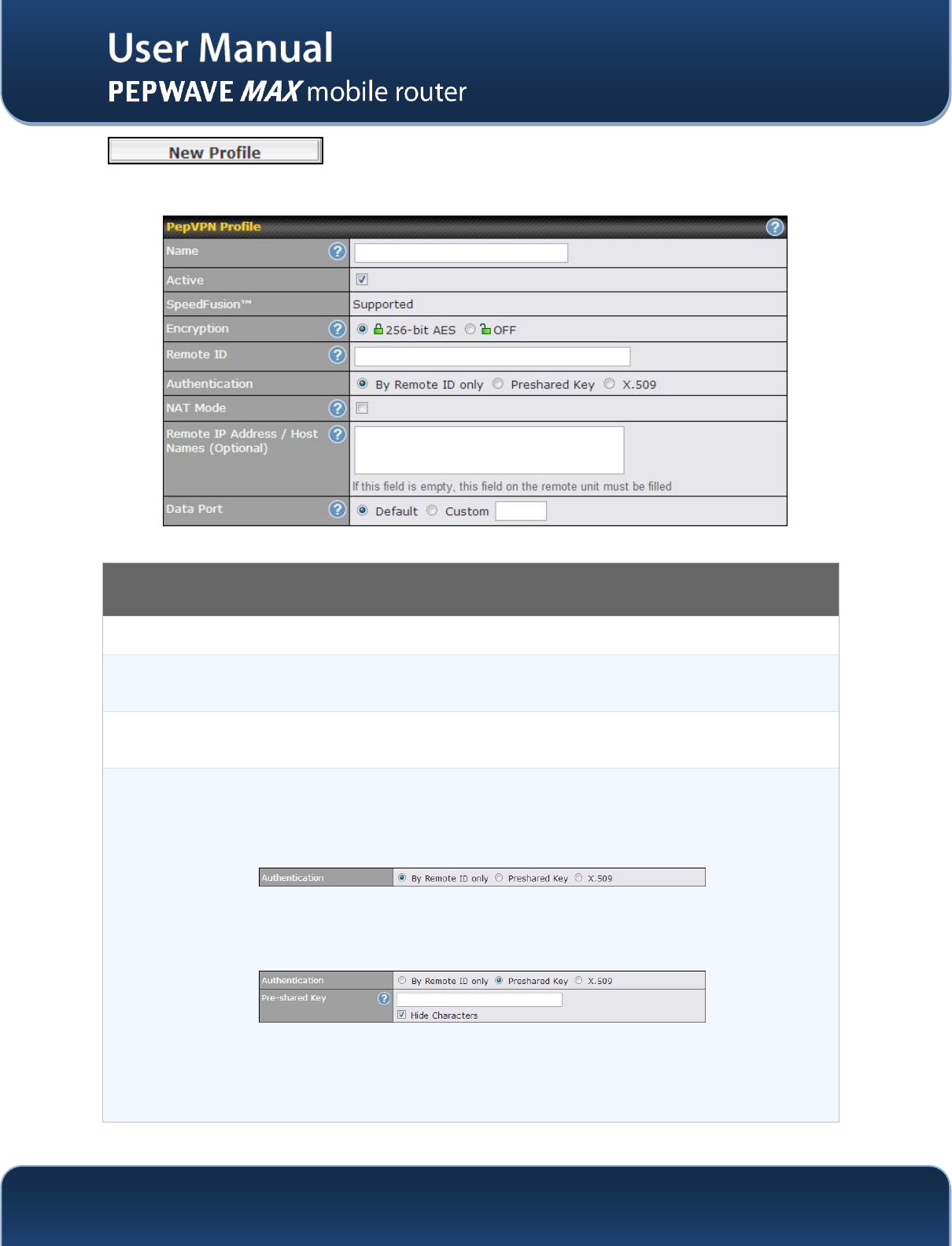
http://www.pepwave.com
63
Copyright @ 2014 Pepwave
to create a new VPN profile.Each profile is for making VPN connection
with one remote Peplink Balance/Pepwave MAX. Once you click on New Profile button this will open a
window:
PepVPN Profile
Active
Check this box to enable VPN functionality.
Encryption
By default, VPN traffic is encrypted with 256-bit AES standard. If the option Off is selected
on both sides of a VPN connection, no encryption will be applied.
Remote ID
The Pepwave MAX establishes VPN connection with a remote peer that has a serial
numberor a remote ID here.
Authentication
Select from By Remote ID Only, Preshared Key, or X.509 to specify the method the
Pepwave MAX will use to authenticate peers. When selecting By Remote ID Only, be sure
to enter a unique peer ID number in the Remote ID field.
Remote ID:
To allow the Pepwave MAXto establisha VPN connection with a specific remote peer using
a unique identifying number.
Preshared Key:
Pre-shared Key defines the pre-shared key used for this particular VPN connection. The
connection will be up only if the pre-shared keys on each side match.When the peer is
running firmware 5.0+, this setting will be ignored. If you would like to prevent the display of
the pre-shared key, check Hide Characters.
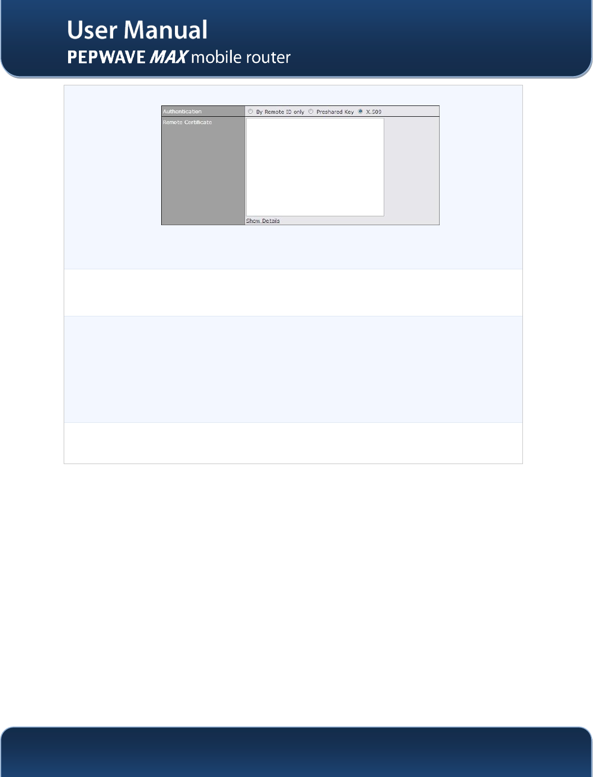
http://www.pepwave.com
64
Copyright @ 2014 Pepwave
X.509
To authenticate VPN connections using X.509 certificates, copy and paste certificate details
into this field. To get more information on a listed X.509 certificate, click the Show Details
link below the field.
NAT Mode
By selecting this option, the remote unit VPN will be assigned with an IP address from the
local DHCP server. All the remote side traffic via this VPN will go through Network Address
Translation (NAT) using the assigned IP address.
RemoteIP
Addresses / Host
Names
Enter the remote peer’s WAN IP address(es) or host name(s) here. Dynamic-DNS host
names are accepted.
This field is optional. With this field filled, the Pepwave MAX will initiate connection to each
of the remote IP addresses until success. If the field is empty, the Pepwave MAX will wait
for connection from the remote peer. Therefore, at least one side of the two VPN peers has
to have the field filled. Otherwise, VPN connection cannot be established.
Enter one IP address or host name per line.
Data Port
If Default is selected, VPN data will go through UDP port 4500.
SelectCustom and enter a port number if a specific outgoing port is desired.
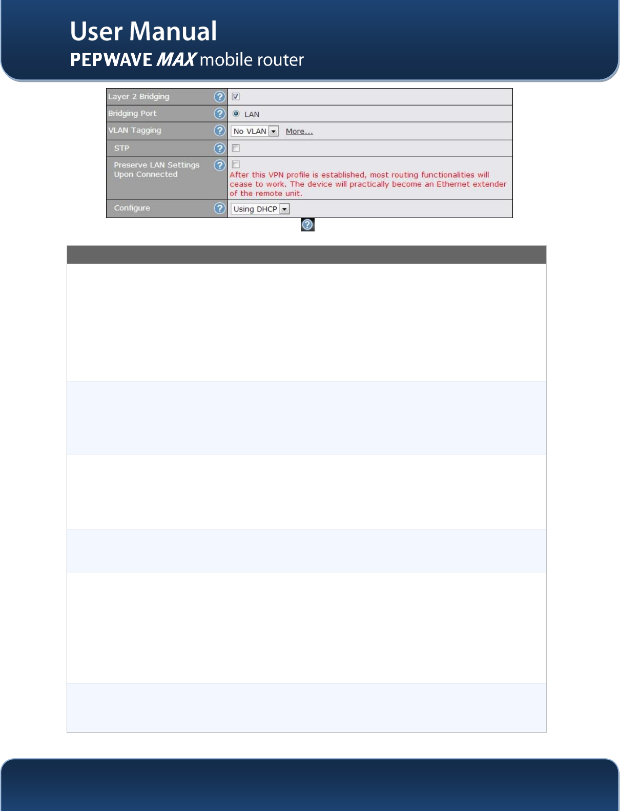
http://www.pepwave.com
65
Copyright @ 2014 Pepwave
ALayer 2 Bridging is an advanced feature, click the icon next to PepVPN profile to activate it, then click
the box next to Layer 2 Bridging to see all configuration options.
Layer 2 Bridging
Layer 2 BridgingA
When this check box is unchecked, traffic between local and remote networks will be IP
forwarded.
To bridge the Ethernet network of an Ethernet port on a local and remote network, select
this check box. When this check box is selected, the two networks will become a single
LAN, and any broadcast (e.g., ARP requests) or multicast traffic (e.g., Bonjour) will be sent
over the VPN.
The L2 bridging feature is hidden from the user interface by default. To enable this feature,
user has to click the hidden link at the upper right corner of the SpeedFusionTM Profile table.
Bridge portA
This field specifies the port to be bridged to the remote site.
If you choose WAN X (internal: replace the X by the WAN port number) that WAN will be
disabled for WAN purposes. Instead, the WAN port will be dedicated to bridging with the
remote site. The LAN port will remain unchanged.
VLAN TaggingA
This field specifies the VLAN ID with which the VPN's traffic should be tagged before
sending the traffic to the bridge port. If no VLAN tagging is needed, select No VLAN. To
define a new VLAN ID, click New... and input the VLAN ID. VLAN IDs that are not
referenced by any VPN profiles will be removed from the list automatically. Default: No
VLAN
STPA
Checking this box enables Spanning Tree Protocol.
Default: Unchecked.
Preserve LAN
Settings Upon
ConnectedA
The LAN port is chosen as the bridge port. Selecting this option preserves LAN settings
(e.g., LAN port IP address, DHCP server, etc.) when the Layer 2 VPN is connected.
Uncheck this option if the LAN IP address and gateway will use remote LAN settings.
Check this option if the LAN IP address and local DHCP server should remain unchanged
after the VPN is up.
If you choose not to preserve LAN settings when the VPN is connected, the device will not
act as a router, and most Layer 3 routing functions will cease to work.
ConfigureA
Use this setting to specify how a management IP address is acquired for the bridge port in
the specified VLAN (if defined) when the Layer 2 bridge is connected. If you choose As
None, no IP address will be assigned to the bridge port for the Layer 2 connection.
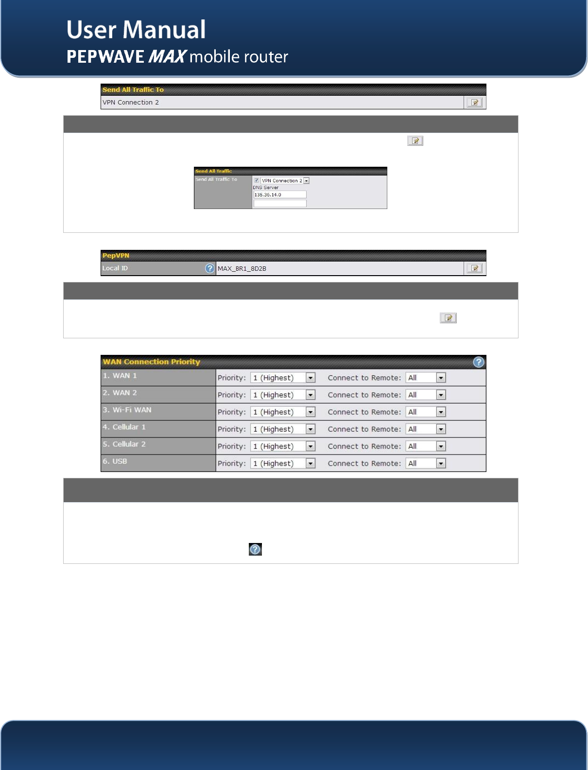
http://www.pepwave.com
66
Copyright @ 2014 Pepwave
Send All Traffic To
This feature allows you to redirect all traffic to a specified PepVPN connection. Click the button to select your
connection and the following menu will appear:
You could also specify a DNS server to resolve incoming DNS requests
PepVPN Local ID
The Local ID is a text string to identify this local unit when establishing a VPN connection. When creating a profile
on a remote unit, this Local ID has to be inputted in the remote unit's "Remote ID" field. Click the icon to edit
your Local ID.
WAN Connection Priority
WAN Connection
Priority
You can specify the priority of the WAN connections to be used for making VPN
connections. WAN connections set to OFF will never be used. Only available WAN
connections with the highest priority will be utilized.To enable connection mapping to
remote WAN, click the button.
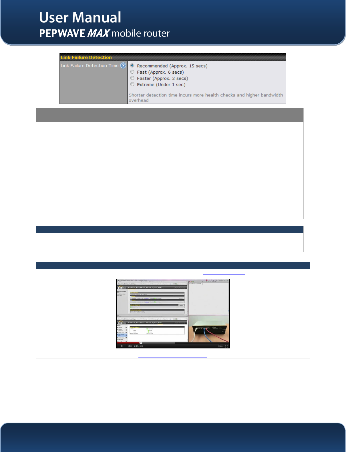
http://www.pepwave.com
67
Copyright @ 2014 Pepwave
Link Failure Detection
Link Failure
Detection Time
The bonded SpeedFusionTMcan detect routing failures on the path between two sites
over each WAN connection. Failed WAN connections will not be used to route VPN
traffic. Health check packets are sent to the remote unit to detect any failure. The more
frequent checks it sends, the shorter detection time, but the higher bandwidth overhead
will be consumed.
When Recommended is selected, a health check packet is sent out every 5 seconds, and
the expected detection time is 15 seconds.
When Fast is selected, a health check packet is sent out every 3 seconds, and the
expected detection time is 6 seconds.
When Faster is selected, a health check packet is sent out every 1 second, and the
expected detection time is 2 seconds.
When Extreme is selected, a health check packet is sent out every 0.1 second, and the
expected detection time is under 1 second.
By default, Recommended is selected.
Important Note
Pepwave’s proprietary SpeedFusionTM used TCP port 32015 and UDP port 4500 for establishing VPN
connections. If you have a firewall in front of the devices, you will need to add firewall rules for these port and
protocols which will allow inbound and outbound traffic pass-through the firewall.
Tip
Want to know more about VPN Sub-Second Session Failover? Visit our YouTube Channel for a video tutorial!
http://youtu.be/TLQgdpPSY88
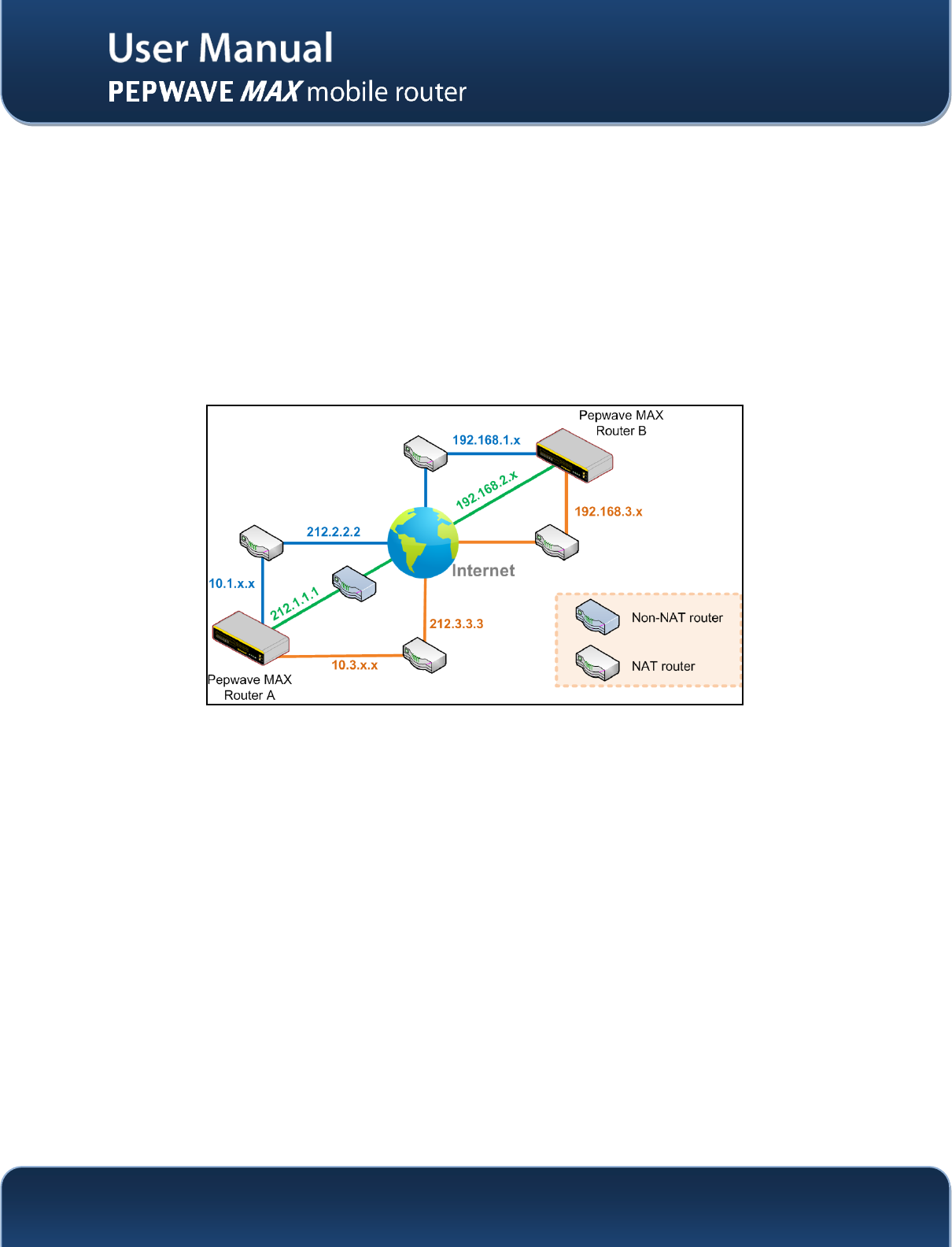
http://www.pepwave.com
68
Copyright @ 2014 Pepwave
11.2 Pepwave MAX Behind NAT Router
The Pepwave MAX supports establishing SpeedFusionTMover WAN connections which are behind a NAT
(Network Address Translation) router.
To be able for a WAN connection behind a NAT router to accept VPN connections, you can configure the
NAT router in front of the WAN connection to forward TCP port 32015 to it.
If one or more WAN connections on Unit A can accept VPN connections (by means of port forwarding or
not) while none of the WAN connections on the peer Unit B can do so, you should put all public IP
addresses or host names of the Unit A to the Unit B’s RemoteIP Addresses / Host Namesfield. Leave
the field in Unit A blank.With such setting, SpeedFusionTM connection can be set up and all WAN
connections on both sides will be utilized.
For example, see the following diagram:
One of the WANs of RouterA is non-NAT’d (212.1.1.1).The rest of the WANs on RouterA and all WANs
on RouterB are NAT’d. In such case, the RemoteIP Addresses / Host Names field in RouterB should
be filled with all of the RouterA’s host names or public IP addresses (i.e. 212.1.1.1, 212.2.2.2 and
212.3.3.3), and the field in RouterA can be left blank. The two NAT routers on WAN1 and WAN3 of
Router A should inbound port forward TCP port 32015 to the Router A so that all WANs would be utilized
to establish VPN.
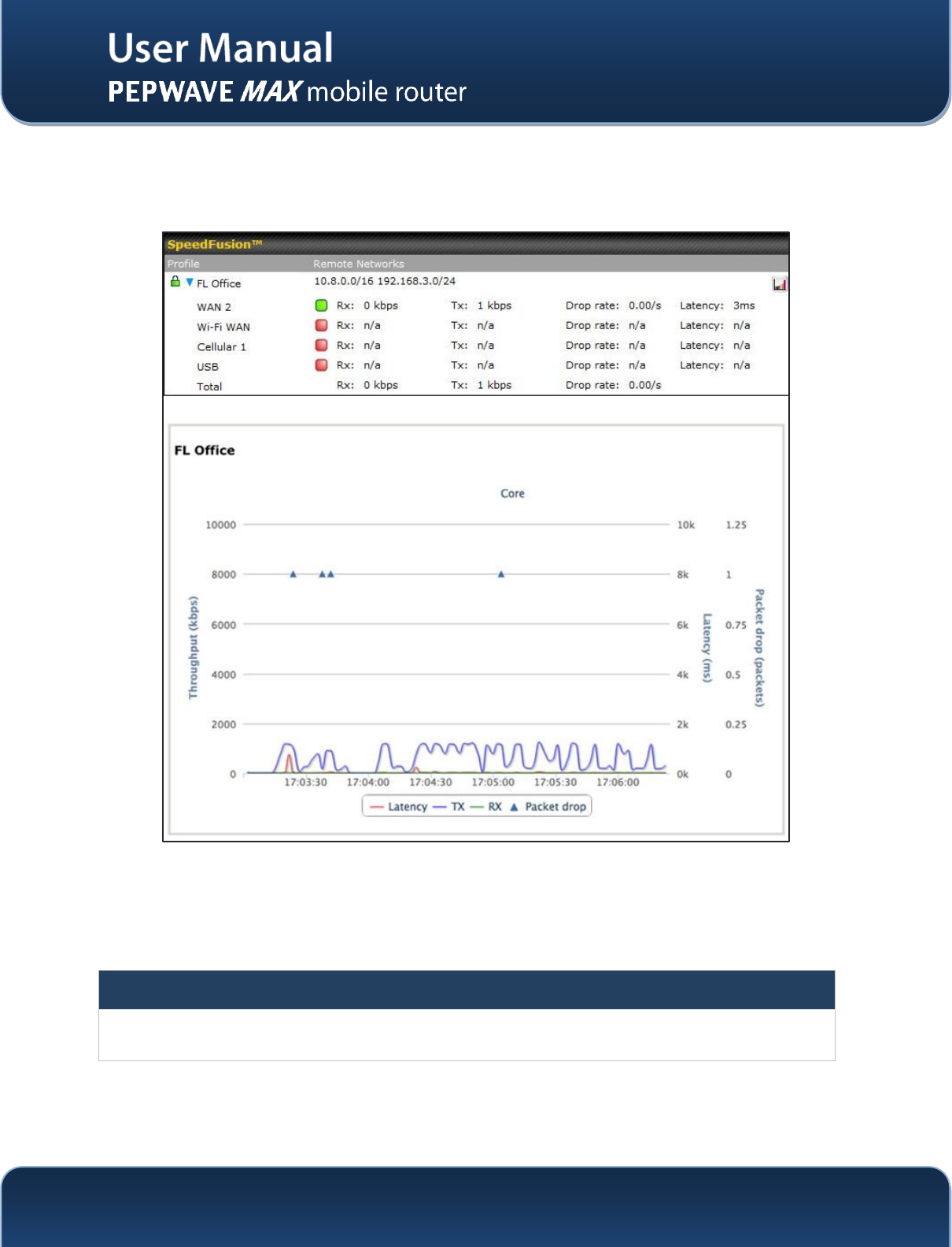
http://www.pepwave.com
69
Copyright @ 2014 Pepwave
11.3 SpeedFusionTM Status
VPN Status is shown in the Status> SpeedFusionTM. The connection status of each connection profile is
shown as below:
By clicking the Details button at the top-right hand corner of SpeedFusionTMtable, you will be forwarded to
Status >SpeedFusionTM. You can view the subnet and WAN connection information of each VPN peer.
Please refer to Section21.5 for details.
IP subnets must be unique among VPN peers
The entire inter-connected SpeedFusionTM network is one single non-NAT IP network. No two subnets in two sites
shall be duplicated. Otherwise, connectivity problems will be experienced in accessing those subnets.
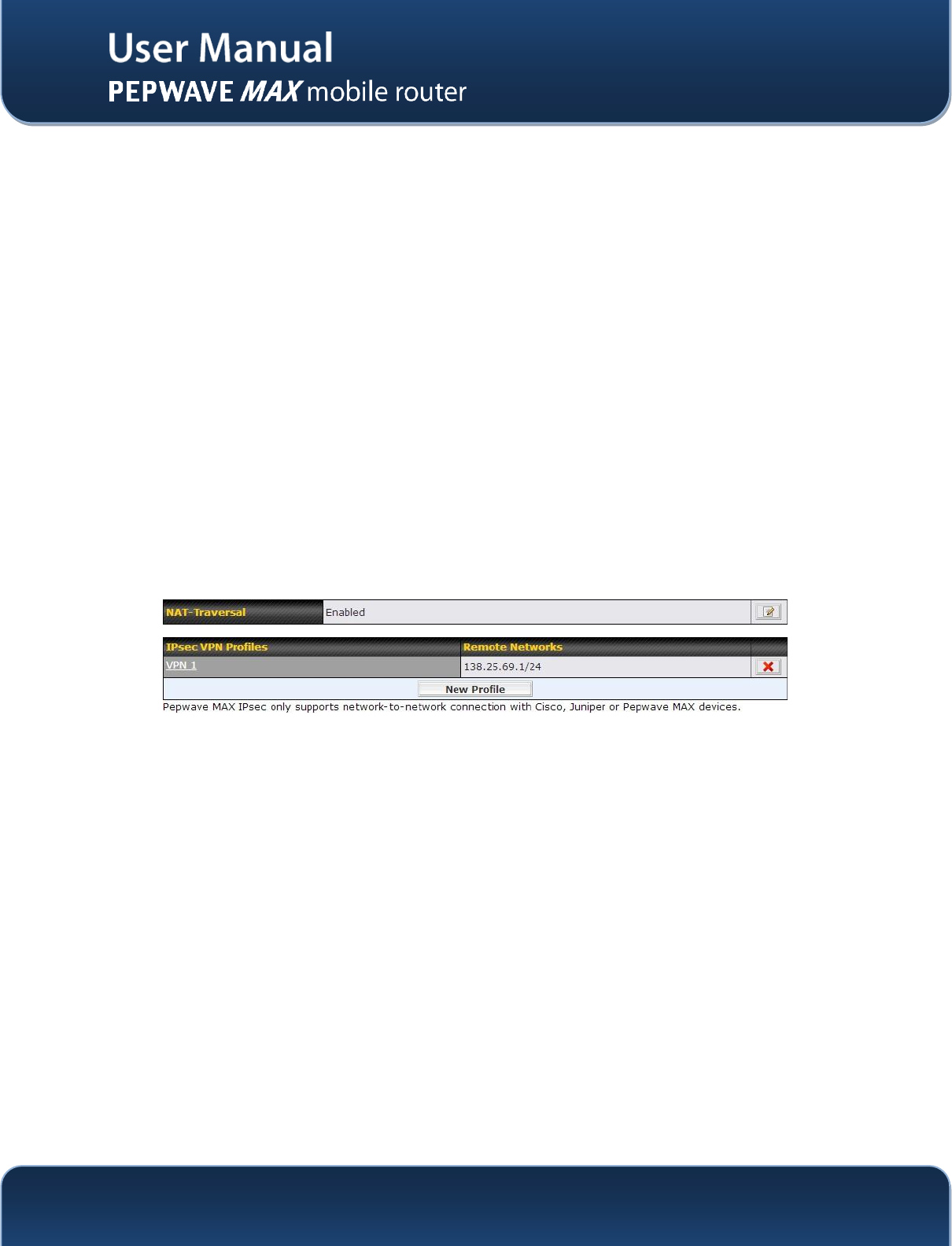
http://www.pepwave.com
70
Copyright @ 2014 Pepwave
12 IPsec VPN
The Pepwave MAX’s IPsec VPN functionality securely connects one or more branch offices to your
company's main headquarters or to other branches.The data, voice, or video communications between
these locations are thus kept safe and confidential across the public Internet.
The IPsec VPN of the Pepwave MAX is especially designed for a multi-WAN environment. For instance, a
user sets up multiple IPsec profiles for his multi- WAN1 ~ WAN3 environment, if WAN1 is connected and
its health check turns up good, the IPsec traffic will go through this link. However, should unforeseen
problems (e.g. physically unplugged or ISP problems) arise and cause WAN1 to go down, our IPsec
implementation will make use of WAN2 and WAN3 accordingly, as failover purposes.
12.1 IPsec VPN Settings
All of our Pepwaveproducts can makemultiple IPsec VPN connections with Peplink, Pepwave as well as
Cisco or Juniper Routers.
Note that all LAN subnet and subnets behind it have to be unique.Otherwise, VPN members will not be
able to access each other.
All data can be routed over the VPN with a selection of encryption standards such as 3DES, AES-128
and AES-256.
To configure, navigate to Advanced>IPsec VPN:
A NAT-Traversal option and list of definedIPsec VPN profiles will be shown.
The NAT-Traversal option should be enabled if your system is behind a NAT router.
Click the New Profilebutton to create new IPsec VPN profiles that make VPN connections to remote
Peplink Balance, Pepwave MAX, Cisco or Juniper Routers via the available WAN connections. To edit
any of the profiles, click on its associated connection name in the leftmost column.
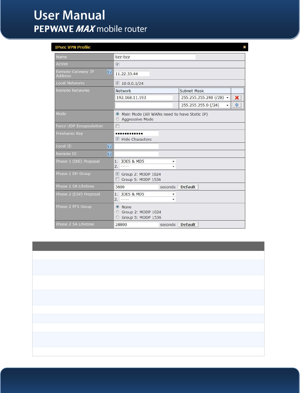
http://www.pepwave.com
71
Copyright @ 2014 Pepwave
IPsec VPN Settings
Name
This field is for specifying a local name to represent this connection profile.
Active
When this box is checked, this IPsec VPN connection profile will be enabled. Otherwise, it
will be disabled.
Remote Gateway
IP Address
Enter the remote peer’s public IP address.For Aggressive Mode, this is optional..
Local Networks
Enter the local LAN subnets here. If you have defined “static routes”, they will be shown
here too.
Remote Networks
Enter the LAN and subnets that are located at the remote site here.
Main Mode
Choose this Main Mode if both IPsec peers use static IP addresses.
Aggressive Mode
Choose this Aggressive Mode if one of the IPsec peers use dynamic IP addresses.
Force UDP
Encapsulation
For UDP encapsulation to be forced regardless of the NAT-Traversal, tick this checkbox.
Pre-shared Key
This defines the peer authentication pre-shared key to be used to authenticate this VPN
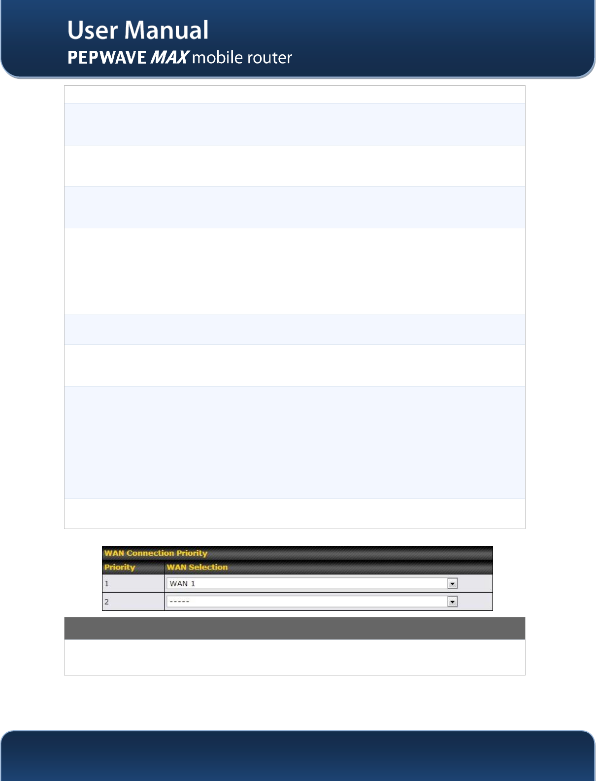
http://www.pepwave.com
72
Copyright @ 2014 Pepwave
connection. The connection will be up only if the pre-shared keys on each side match.
Local ID
Under Main Mode, this field can be left blank.
Under Aggressive Mode, if Remote Gateway IP Address field is filled on this end and the
peer end, this field can be left blank. Otherwise, this field is typically a U-FQDN.
Remote ID
Under Main Mode, this field can be left blank.
Under Aggressive Mode, if Remote Gateway IP Address field is filled on this end and the
peer end, this field can be left blank. Otherwise, this field is typically a U-FQDN.
Phase 1 (IKE)
Proposal
Under Main Mode, this allows the setting of up to 6 encryption standards, in descending
order of priority, to be used in the initial connection key negotiations.
For Aggressive Mode, only one selection is permitted.
Phase 1 DH Group
This is the Diffie-Hellman group used within IKE. This allows two parties to establish a
shared secret over an insecure communications channel. The larger the group number, the
higher the security.
Group 2 - 1024-bit is the default value.
Group 5 - 1536-bit is the alternative option.
Phase 1 SA
Lifetime
This setting specifies the lifetime limit of this Phase 1 Security Association. By default, it is
set at 3600 seconds.
Phase 2 (ESP)
Proposal
Under Main Mode, this allows the setting of up to 6 encryption standards, in descending
order of priority, to be used for the IP data that is being transferred.
For Aggressive Mode, only one selection is permitted.
Phase 2 PFS
Group
The Perfect Forward Secrecy (PFS) ensures that if a key was compromised, the attacker
will be able to access only the data protected by that key but not any other data.
None - Do not request for PFS when initiating connection. However, since there is no valid
reason to refuse PFS, the system will allow the connection to use PFS if requested by the
remote peer. This is the default value.
Group 2 - 1024-bit Diffie-Hellman group. The larger the group number, the higher the
security.
Group 5 - 1536-bit is the third option.
Phase 2 SA
Lifetime
This setting specifies the lifetime limit of this Phase 2 Security Association. By default, it is
set at 28800 seconds.
WAN Connection Priority
WAN Connection Select the appropriate WAN connection with the help of drop down