Point Mobile PM60-1 Mobile Computer(PDA) with WCDMA/GSM/BT/WLAN transmitter User Manual KTL PM60 FCC CE CB
POINTMOBILE CO., LTD. Mobile Computer(PDA) with WCDMA/GSM/BT/WLAN transmitter KTL PM60 FCC CE CB
UserManual.wiki
>
Point Mobile
>
PM60 1 User Manual
User Manual
Navigation menu
Upload a User Manual
Namespaces
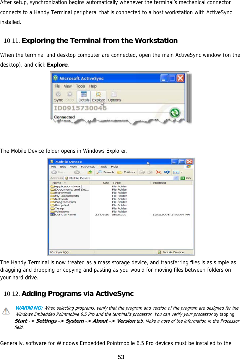
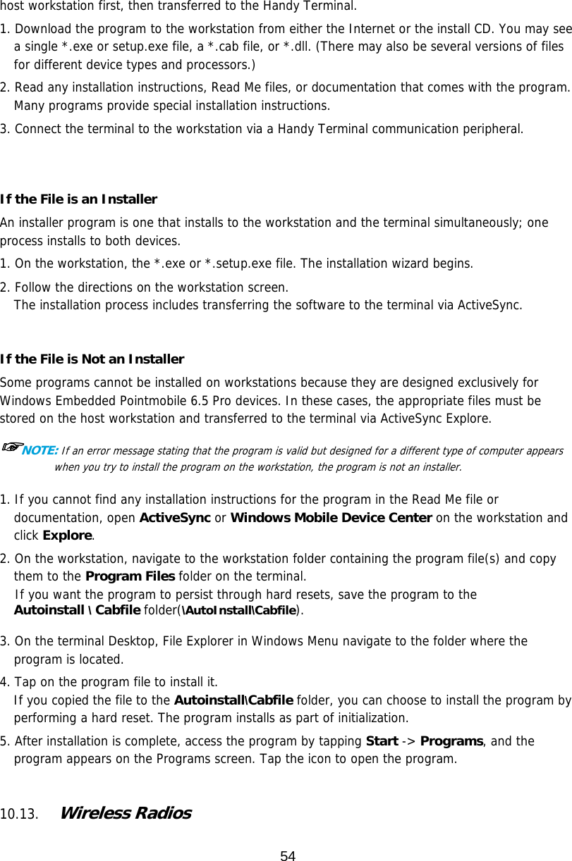
Wiki Guide
HTML
PDF
Info
Views
User Manual
Discussion / Help
Navigation
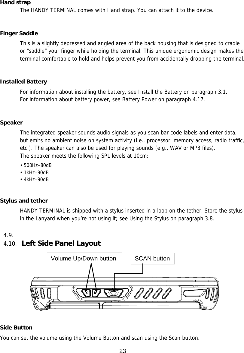
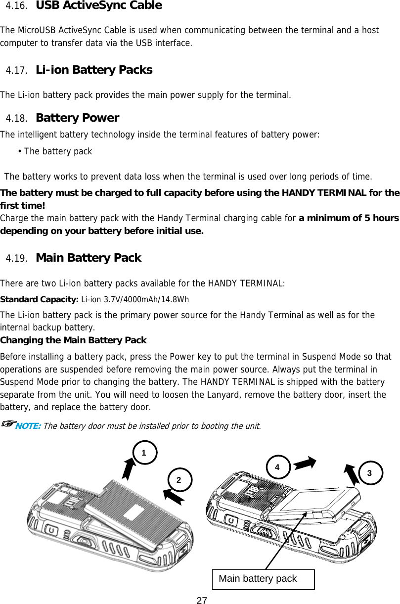
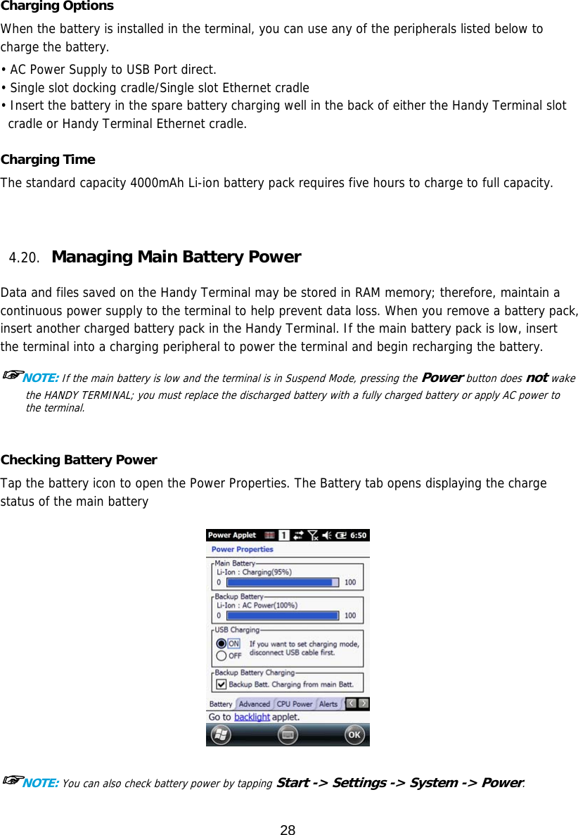
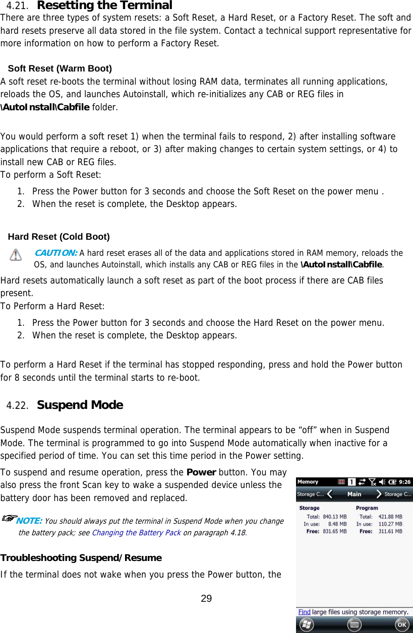
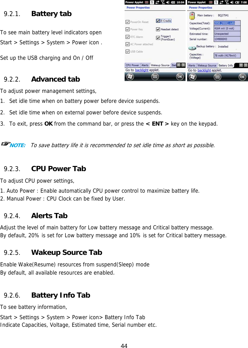
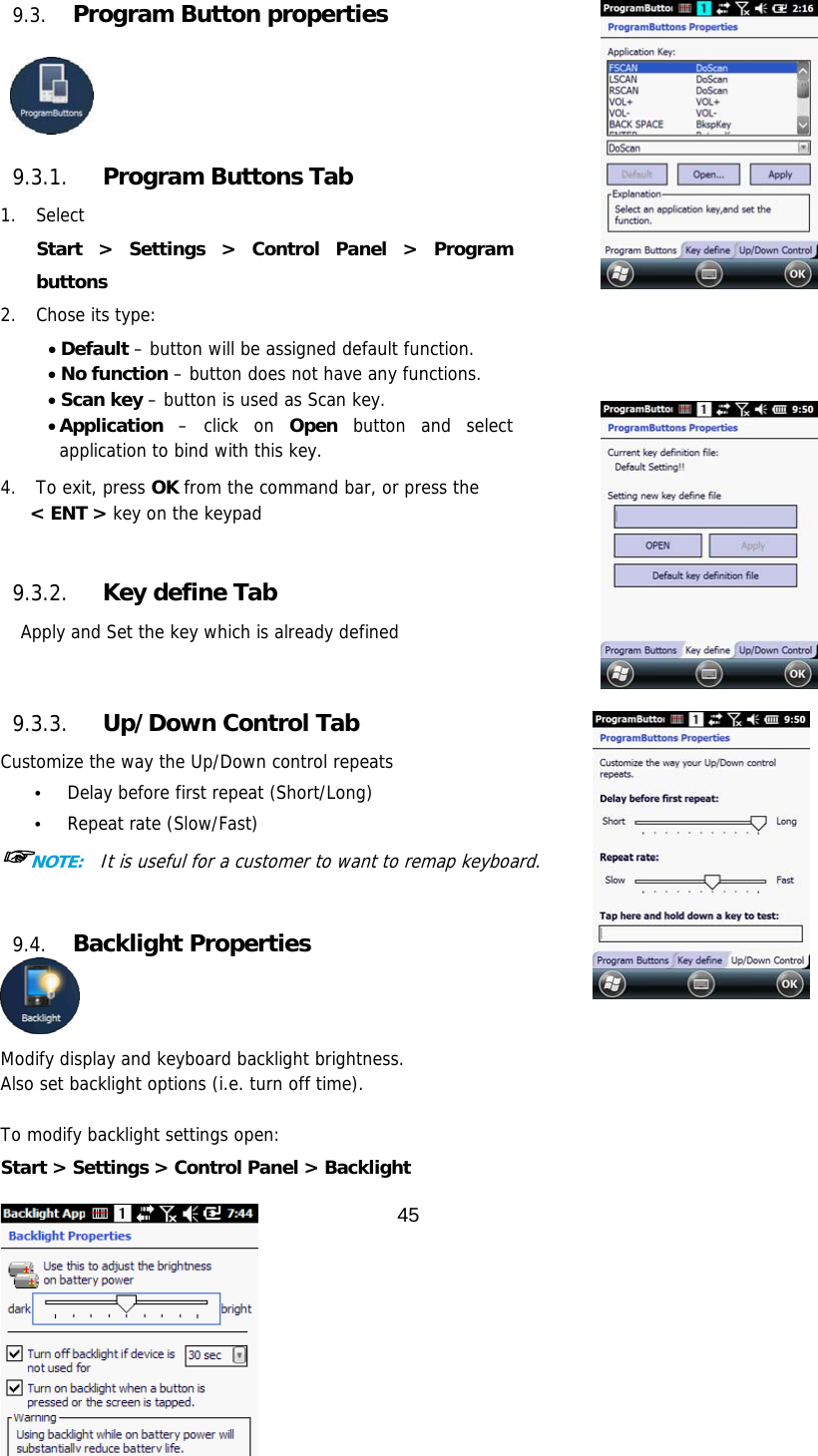
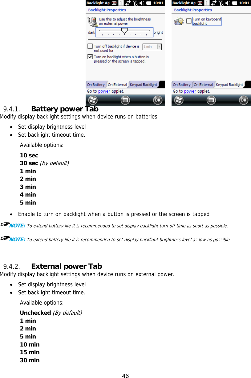
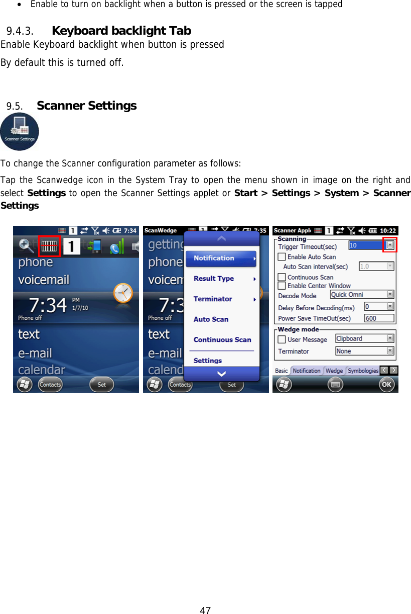
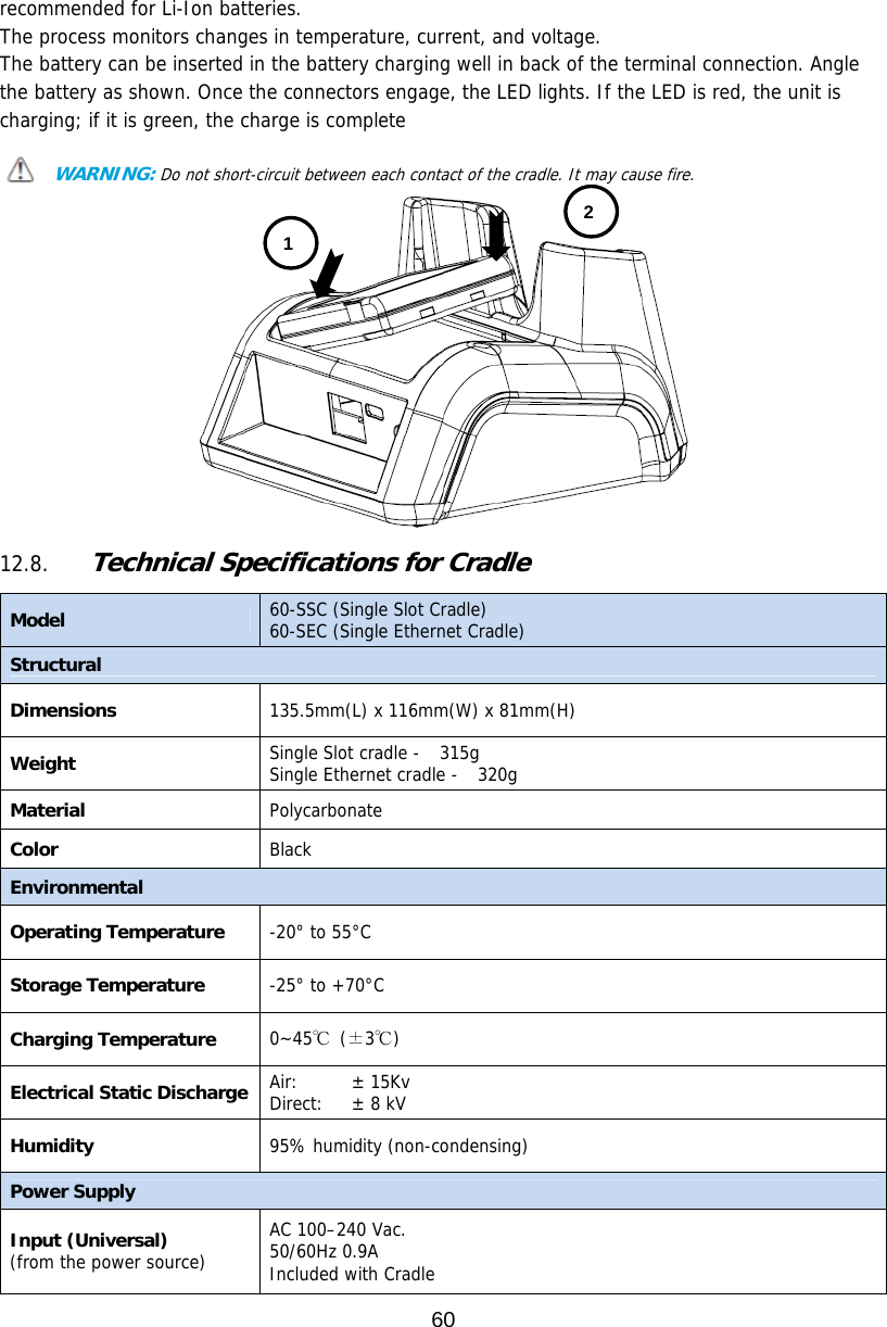
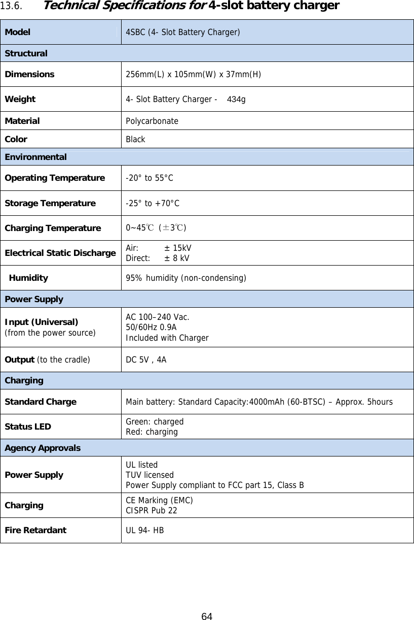
![39 The aiming pattern is smaller when the terminal is held closer to the code and larger when the terminal is held farther from the code. Symbologies with smaller bars or elements (mil size) should be read closer to the unit whereas larger bars or elements (mil size) should be read farther from the unit. 6.11. Capturing Images The image-capture process is an intuitive, split-second operation for experienced users. By following basic guidelines, however, new users can easily develop their own technique and, with practice, quickly learn to adapt to different application environments. Image Preview When the imaging process is initiated, the touch screen displays a preview of the object. This is a live video image of what the imager is currently viewing and has a slightly degraded appearance compared to the captured image. This is normal; the captured image has a higher resolution. File Formats The Handy Terminal supports BMP file format only. 7. Using the Laser Engine 7.1. Overview The HANDY TERMINAL (N4313 laser version) contains a laser diode that emits a beam toward an oscillating mirror that scans through the code and the reflected light is bounced off of two mirrors back to the collector. The laser version reads all popular 1D bar codes. See Overview on paragraph 6.1 also. ☞NOTE: Performance may be impacted by bar code quality and environmental conditions. 7.2. Available Laser Engines The HANDY TERMINAL can be equipped with an N4313 laser engine (depending on the configuration purchased). 7.3. Depth of Field Depth of Field for N4313 Code Size Reference Range Near Distance (in/cm) Far Distance (in/cm) Code 39 4 mil 5in / 12.7cm 5.4in / 13.8cm Code 39 5 mil 4.1in / 11.7cm 7.2in / 18.4cm 메모 [W1]: N560x 도 추가요함.](https://usermanual.wiki/Point-Mobile/PM60-1/User-Guide-2476981-Page-40.png)