Powerhouse Dynamics 950-000018 Z-Wave Networking Module User Manual eMonitorTM Version 1
Powerhouse Dynamics, Inc. Z-Wave Networking Module eMonitorTM Version 1
Users manual
Installation Guide
Last Update - December, 2014
Installation Process: Quick Overview
Please review the full Installation Guide before proceeding; this Overview provides basic steps for
installing the SiteSage Gateway and Energy Monitor, but not the level of detail you will need to safely
install these and other SiteSage components. Installation should only be performed by a licensed
electrician.
Step 3: Plug in the SiteSage Gateway at a secure location within about 30 feet of the electric panels to
be monitored, and connect it to the broadband Internet network in the facility. SiteSage can be
connected either by Wi-Fi or via a wired Ethernet connection, as described in Section 2. Once
the Gateway is connected to the Internet, the LINK light on the Gateway will turn solid green.
When an Energy Monitor unit has been installed and registered and is seen by the Gateway, the
DATA light will turn solid green as well.
Step 2: Turn off power to the circuit panel where the SiteSage Energy Monitor components are being
installed and open the panel. Connect the black wire of the power cable to an empty (15A or
20A) breaker and the white wire to the neutral bar. Clamp the appropriate-size current
transformer/sensors, first
onto the incoming Main
power lines (if they are
being monitored), and then
onto all branch circuits
being monitored, recording
each circuit’s information on the Channel Setup Worksheet as you go.
Step 3: Connect the other end of the sensors to the Channels (ports) on the SiteSage
Energy Monitor “ePod” and “xPods”, if any, as described in Section 3. Place
the provided labels on the sensors and the wire near the Channel
connections to keep track of which circuits have been connected to which
SiteSage Monitor Channels. Connect the other end of the power cable to
the SiteSage Monitor ePod and find a convenient space to mount the unit
inside the panel. (Make sure the ePod is not powered up until all the xPods
have been connected). You can then organize the wires with the provided
wire ties. Close the circuit panel, turn power back on, and plug the SiteSage
Gateway into an electrical outlet.
Step 4: Register and configure SiteSage online. Please go to
http://SiteSage.net/setup and follow the on-screen instructions. This
process can, but need not, be completed by the person who installed the unit, and will require
completed Channel Setup Worksheets. A Software License Key, which should be provided by
the Authorized SiteSage Channel Partner, is also required for Registration. After the
Registration and Configuration process is completed it is possible to access the SiteSage Portal at
Sitesage.net. You are then able to configure the SiteSage Smart Thermostats. (See Section 4).
NOTE: In the case of 3-Phase power, it is best practice to install all sensors is the same direction, with
the arrows FACING the breaker panel (or, in the case of 150A sensors, with the label facing AWAY
from the panel). Please see Section 3.2 for further explanation.
© 2014 Powerhouse Dynamics, Inc. Page 2
SiteSage Installation Guide
Table of Contents
Installation Process: Quick Overview ...................................................................................... 2
Important Safety Information ................................................................................................. 4
1. Introduction to SiteSage ...................................................................................................... 5
2. Setting up the SiteSage Gateway ........................................................................................ 6
2.1 Installing the SiteSage Gateway .................................................................................... 6
2.2 Connecting to the Internet ........................................................................................... 7
3. Installing a SiteSage Energy Monitor ................................................................................. 12
3.1 Channel Setup Worksheet ......................................................................................... 12
3.2 Installing the SiteSage Energy Monitor Components ................................................ 17
3.3 Installation of Other Sensors ..................................................................................... 25
4. Installing SiteSage Smart Thermostats .............................................................................. 26
5. Registering and Configuring SiteSage ................................................................................ 29
Step 1: Account and Contact Information ...................................................................... 30
Step 2: Location Information .......................................................................................... 30
Step 3: Utility Rates ........................................................................................................ 31
Step 4: Energy Monitor Channel Configuration ............................................................. 32
Step 5: Configuring a Smart Thermostat ........................................................................ 37
Appendix A: Frequently Asked Questions ............................................................................ 40
Appendix B: Provisioning a Wi-Fi Smart Thermostat ........................................................... 41
Appendix C: SiteSage Networking Requirements ................................................................ 44
Appendix D: Installing Temperature Sensors ....................................................................... 46
Appendix E: SiteSage Hardware Technical Specifications .................................................... 50
Warnings ........................................................................................................................... 50
Warranty ........................................................................................................................... 53
© 2014 Powerhouse Dynamics, Inc. Page 3

Important Safety Information
NOTE: Installation should not be started until the qualified installer has read this entire
Installation Guide.
SiteSage can monitor all of the circuits in a facility independently, and therefore provide a
detailed view of electricity usage. In order to do this, sensors need to be installed on circuit
breakers inside the electrical panels. The installation is very straightforward and every effort
has been made to provide for the safe, secure installation of the SiteSage components.
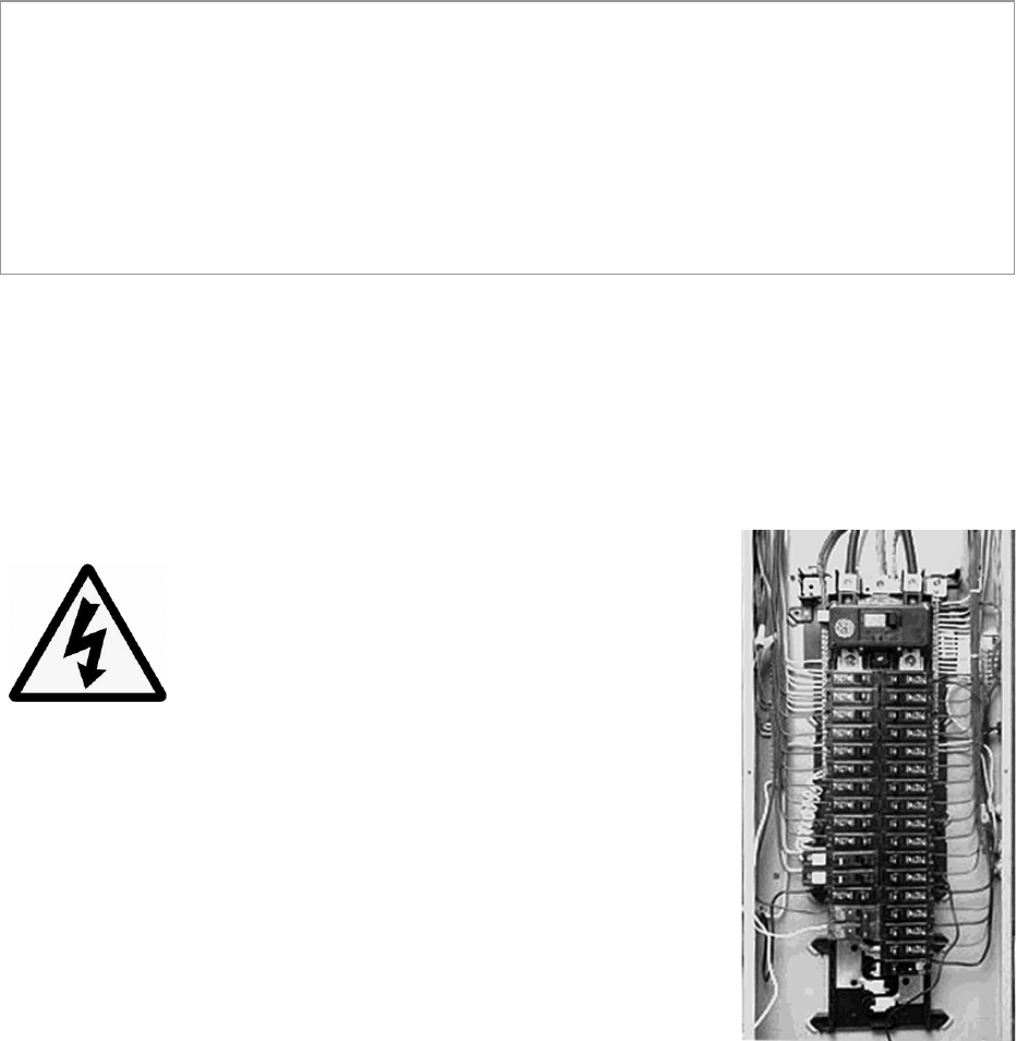
However, the installation of SiteSage Energy Monitor units requires the cover of the electrical
circuit breaker panels to be removed.
When this is done, there is the potential hazard of shock, burn,
or even electrocution.
Even when the Main Circuit Breaker has been turned to the
“OFF” position, there may still be areas within the circuit
breaker panel that are electrified, or “hot”. Installation should
be performed by a licensed electrician only.
SiteSage is suitable for installation with 120/240V single-phase 60Hz service as well as 3-phase
208v or 480v service normally found in North America. It is not suitable for 230V 50Hz service
commonly found in other regions of the world. (This version of SiteSage also does not support
346/600V service still in use in parts of Canada).
All wiring in the United States must be installed in accordance with the
latest adopted edition of the National Electrical Code (ANSI/NFPA 70,
NEC) and state or local requirements. All wiring in Canada must be
installed in accordance with the latest adopted edition of the Canadian
Electrical Code (CSA C22.2 CEC, Part I) and any provincial or local
requirements.
A typical installation of a SiteSage Energy Monitor with 25 channels
should take approximately one hour.
© 2014 Powerhouse Dynamics, Inc. Page 4
1. Introduction to SiteSage
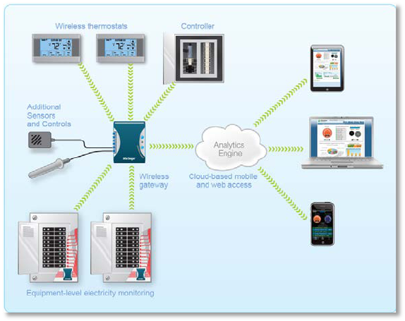
SiteSageTM is an Enterprise Energy and Asset Management System that combines controls,
monitoring, diagnostics, and alerts designed to reduce energy costs and enhance operational
efficiencies across multiple small commercial facilities. Hardware components will vary from
location to location depending upon both the physical layout and the roles that the system is
intended to play. This Installation Guide addresses the hardware components most likely to be
included. Additional documentation may be required if other components are being added.
The SiteSage Energy Monitors and Smart Thermostats connect wirelessly to the SiteSage
Gateway, which in turn connects to the broadband infrastructure in the facility. This document
covers the tasks of connecting the Gateway, installing the Energy Monitors, and configuring the
system as a whole and the Energy Monitors and Smart Thermostats specifically. Instructions for
installing the Smart Thermostats are included with the specific thermostats purchased.
© 2014 Powerhouse Dynamics, Inc. Page 5
2. Setting up the SiteSage Gateway
The core of the system is the SiteSage Gateway. All other SiteSage hardware components
connect to the Gateway, either wired or wirelessly. The Gateway then connects to the
broadband infrastructure in the facility, either via Ethernet or Wi-Fi, and provides the
connection to the SiteSage Portal. It uploads data on a minute by minute basis and brings back
new settings or commands. It is a small device (5.25” x 3.25” x 1.5”) that can be mounted on
the wall or placed on a table, ideally within about 30 feet of the electric panels it is connecting
to. Multiple Gateways may be required, either because of distance constraints or device
number constraints. (A single Gateway can connect to at most 10 electric panels).
Best practice is to install the Gateway first, although that is not a requirement.
2.1 Installing the SiteSage Gateway
Physically installing SiteSage Gateway is extremely simple. You can hang it on the wall with the
brackets provided, or place it on a table. Find a location within approximately 30 feet of the
electric panel(s) in which you will be installing SiteSage Energy Monitors, and near a 120 volt
power outlet. Attach the Power Supply to the Gateway and plug it in to the wall outlet. NOTE:
If there are multiple electric panels that are not close together, you may need additional
Gateways.
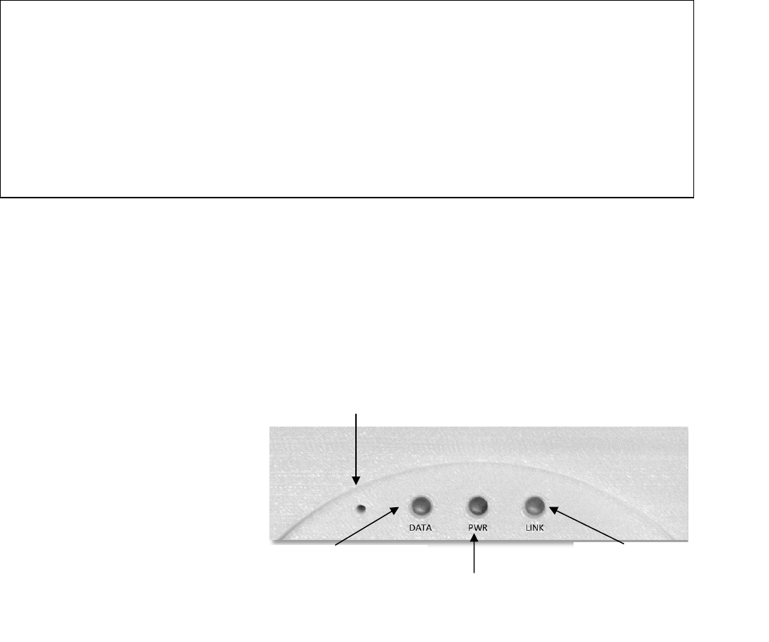
There are 3 LED status lights on
the Gateway. When the Gateway
powers on, the middle one,
marked PWR, should show solid
green, indicating that the
Gateway is drawing power. The
other LED’s will flash 3 times,
NOTE: The Gateway connects all of the SiteSage components to the Internet. If the Gateway
gets unplugged, the SiteSage Energy Monitors, Smart Thermostats, and other sensors will no
longer upload data (although they will collect and store the data – in the case of energy data for
up to 20 days - and the SiteSage controls will no longer accept settings changes. To ensure
uninterrupted operation please make sure to install the Gateway in a place where it is not likely
to be accidentally unplugged. Please note that the system cannot be registered until the
Gateway is connected to the Internet.
Reset
DATA. Turns solid green once at
least 1 SiteSage is successfully
communicating
PWR. Stays solid green
when Gateway is
powered
LINK. Stays solid green when
Gateway is connected to Internet
© 2014 Powerhouse Dynamics, Inc. Page 6

pause, and then go solid for about 2 seconds. If the Gateway has been configured with Wi-Fi,
the LEDs should flash green. If it was configured for Ethernet, they flash red. (If you do a
factory reset, as described later, the final flash will be orange). Subsequently, the LED on the
left, marked DATA, will turn red for 2 seconds when a SiteSage Energy Monitor or Controller
(described in a separate document) is trying to pair with the Gateway. SiteSage will not be able
to successfully communicate until the Gateway has been connected to the Internet1.
2.2 Connecting to the Internet
The SiteSage Gateway is designed to transmit data in near-real time over the Internet to the
SiteSage Servers, where data is analyzed and presented on the SiteSage Portal (described in the
SiteSage User Manual, which is accessible on-line via the Support link of the SiteSage Portal.
Please see Appendix C for system network requirements.
The Gateway connects to a network in one of 2 ways; hard-wired Ethernet or Wi-Fi. Currently
the Gateway needs to be pre-configured for one or the other, although it is possible to change
the configuration remotely as long as the Gateway is connected. (Future versions of the
Gateway will support Ethernet and Wi-Fi simultaneously). If you have multiple Gateways, it is
possible to use Ethernet with some and Wi-Fi on others. Please note that SiteSage needs
Internet access only, and should be installed outside the firewall.
If you are using Ethernet, simply connect the Gateway’s Ethernet port to an Ethernet
connection using a standard Ethernet cable. (If there are no Ethernet ports near the Gateway,
you can use a power line bridge). This is all you need to do unless a static IP address or proxy
server is required for the facility, as described below. In that case, follow the instructions under
Step 2.
1 The Gateway also has 6 ports marked A1-A3 (analog ports) and D1-D3 (digital ports). These are for connecting
other sensors and devices, such as temperature sensors and water meters. Appendix D describes current support
for temperature sensors.
NOTE: You cannot pair a Gateway with a SiteSage Energy Monitor until it is connected to the
Internet. When a Gateway is activated and connected to the Internet, any unpaired but
configured SiteSage Monitors in range should find it and try to pair with it. If there are
multiple Gateways, a Monitor will try to connect to the one with the best signal. (If it ever
resets or loses communications it will again look for the best signal when it comes back on-
line). You can force an assignment to a different Gateway (on the Settings/Channels page on
the SiteSage Portal), but that is not recommended.
© 2014 Powerhouse Dynamics, Inc. Page 7
Many corporate networks will have security settings that do not easily allow systems to be
added to the network, so it may be necessary to have the system pre-provisioned, by providing
the Gateway’s MAC address to the corporate network support group in advance. (Please see
Appendix C for more information on network provisioning).
Alternatively, the SiteSage Gateway includes a Wi-Fi radio. If Wi-Fi is being used as the
connection method, follow the instructions below. (If you are not sure which connection
method was specified, check the Gateway; it should have a Wi-Fi or Ethernet label).
If you need to change a Gateway from Ethernet to Wi-Fi, or vice versa, contact SiteSage Support
(support@sitesage.net). As long as the Gateway can be connected to the Internet, new
firmware can be downloaded to change the connection method. (When new connection
firmware is downloaded you will be disconnected from the Internet and need to re-connect
using the newly downloaded protocol).
Please note that using a public Wi-Fi network is not recommended. Often these systems will
have certain restrictions that may make it difficult to keep SiteSage connected at all times.
Also, SiteSage has no way to acknowledge acceptance of terms. Wi-Fi networks may also
require pre-provisioning, as described in Appendix C.
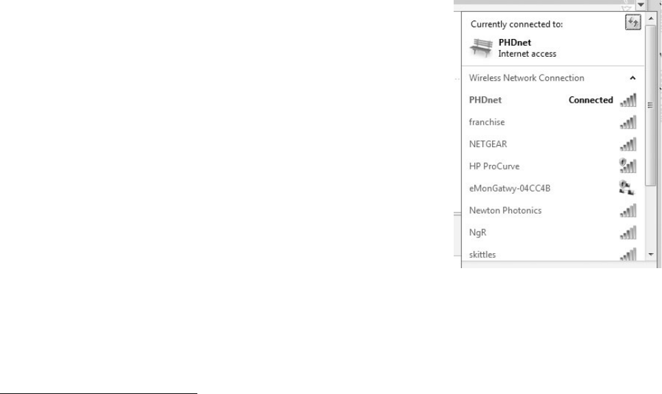
STEP 1 (Wi-Fi only)
When the Gateway turns on, it will create its own (ad hoc) Wi-Fi
network. When the ad hoc mode is established, the LINK light
will alternatively flash red/green for 5 seconds. Using a PC, Mac,
iPhone, or other device that connects to Wi-Fi networks2, follow
the standard process for identifying nearby networks. (Note:
there does not need to be a Wi-Fi network in the facility to see
the Gateway’s ad hoc network).
Find the network with a name like eMonGatwy-xxxxx (these are
the last 6 digits of the MAC address of the Gateway, which can be
found on the Gateway label), and connect to it. If your computer
displays an “unsecured network” message, click “Connect Anyway” and continue connecting to
the Gateway. If the connection was successful, Connected to eMonGatwy-xxxxxx will be
displayed.
2 Android no longer supports a native connection to ad hoc networks. You may be able to download a utility that
will let you connect. There may also be issues with Windows 8.1 and again utilities are available.
© 2014 Powerhouse Dynamics, Inc. Page 8
If you were unable to connect to the Gateway, try the process again. If you still cannot find the
network, do a (hard) factory reset of the Gateway (as described on Page 10) and try again.
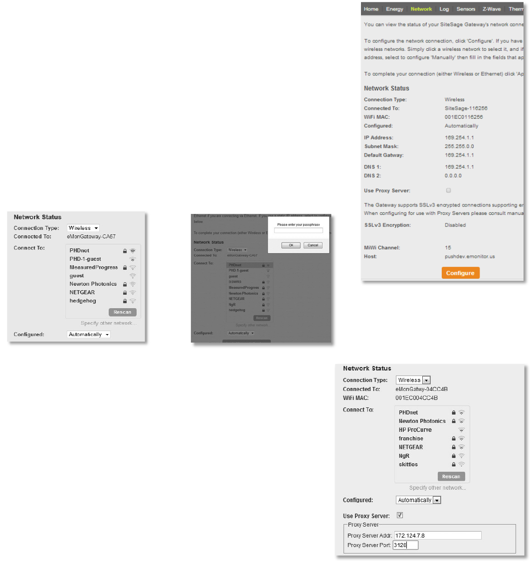
STEP 2 (Wi-Fi; Ethernet for Proxy Server and Static Address)
Enter the address http://169.254.1.1/netcfg.htm in a browser
window. The page shown to the right which is part of the SiteSage
Embedded Web Server, will load. Press Configure and the page will
change to let you set your configuration parameters.
If you are using DHCP, where an IP address is automatically
selected, select Automatically as the configuration method. You will
see a list of available wireless networks displayed in the window.
Click on the facility’s Wi-Fi network to select it. If the network is
password protected, enter the Password. Click Apply Network
Settings and the Gateway will be connected to the network. It may
take 30 seconds or more for the LINK light to turn green to signify
that it is connected, so please be patient.
If you need to attach via a Proxy Server, enter the server
address and port on the Configuration page.
If you want to view or change the settings for any reason, or
simply get back to the Embedded Web Server, you must first
determine the Gateway’s IP address. If you have already
registered the system, log into the SiteSage Portal and go to
Settings/Channels. You will see a link called Gateway
Assignment. Follow that link and you will see the current IP
address of the Gateway. If you have not yet registered and
configured this location (but the account has already been
© 2014 Powerhouse Dynamics, Inc. Page 9
established), go to Sitesage.net/setup, log in, and enter the Gateway’s Serial # (found on the
back of the Gateway), which will return the then current IP address. (Registration and
Configuration is described in Section 5). At any time
you can also find the IP address by looking at the
router’s list of DHCP entries (using the MAC address of
the Gateway that is on the label).
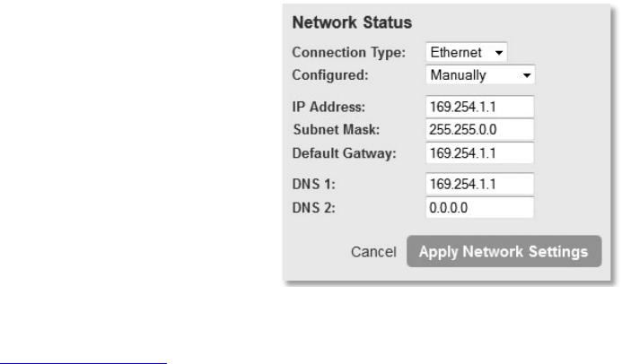
If you want to use a static IP address, select Manual for
the configuration method. (It will default to
Automatic). You will be asked for the Static IP Address,
Subnet Mask, Default Gateway and DNS1 and DNS2
(optional). Then hit Apply Network Settings.
If you have connected via Ethernet and want to set a
static IP address or connect to a proxy server, connect your laptop to the Gateway’s Ethernet
port and enter the address http://169.254.1.1 in your browser. (Make sure to disable any
cellular or Wi-Fi networks on your laptop). You will see the same screens you see here, with
Ethernet as the Connection type. Follow the instructions above to set a static IP address or
connect to a Proxy Server. If you set a static address, you can reconnect to the Gateway at a
later date by entering that address directly.
When the Gateway successfully connects to the facility network, the LINK light will turn and
remain solid green, other than a flash of orange once per minute as data is transmitted. (If you
see solid orange for about 10 seconds that means the Gateway is downloading new firmware;
both the LINK and DATA lights will flash red while the firmware is being loaded). Unpaired but
registered SiteSage Energy Monitors will immediately attempt to connect to the Gateway and
upload data; both the DATA and LINK lights on the Gateway will show solid orange for a couple
of seconds. (This will be repeated whenever data is uploaded or downloaded). When a
SiteSage Energy Monitor has successfully paired with the Gateway, the DATA light will turn
solid green. If you installed the Gateway first, as described here, the DATA light will not do
anything until a SiteSage Energy Monitor unit has been installed and configured.
If there is an error in the setup process, or the network connection fails for any reason, the LINK
light will not turn green. This may happen because you did not enter the security password
correctly, or if the connection was momentarily lost. If it becomes clear that the Gateway is not
connected to the internet, you will need to repeat the steps starting from STEP 1.
To do this, you will first need to do a hard (factory) reset of the Gateway. Press Reset. (Use a
paper clip and pull it out quickly). The DATA and LINK LEDs will flash 5 times, and then turn
solid for 2 seconds. Press Reset again (quickly) while the light is solid and the Gateway should
© 2014 Powerhouse Dynamics, Inc. Page 10
reset to its factory settings. The LEDs will display orange for about 2 seconds when the factory
reset is successful.
STEP 3
When the SiteSage Gateway Internet connection is completed successfully, make sure your
computer has re-connected to the facility network if you are going to be using it to register the
system. If it hasn’t, go back to your network connections screen to re-connect to the network.
Once the Gateway has successfully been connected to the Internet and Energy Monitor units
have been installed and configured, if the DATA light is not solid green, it has not successfully
paired with any SiteSage Energy Monitors. Try moving the Gateway closer to electric panel. If
that does not work, try power cycling the SiteSage Energy Monitor, by flipping the breaker for
the circuit that powers it. If that does not work, try power cycling the Gateway (which will then
need to be reconnected to the Internet). If neither of these works, please contact SiteSage
support.
© 2014 Powerhouse Dynamics, Inc. Page 11

3. Installing a SiteSage Energy Monitor
The SiteSage Energy Monitor is designed to capture data on electrical usage of potentially all
the circuits inside a facility. It consists of a set of sensors, known as Current Transformers (CTs)
and a set of small components, referred to as “Pods”, to which the sensors are attached. Each
installation of the SiteSage Energy Monitor will have 1 electricity Pod (ePod), which can
accommodate up to 15 CTs and communicates wirelessly with the Gateway. It may have 1 or
more expansion Pods (xPods), which are needed if more than 15 circuits are monitored in a
single panel. There is no physical limit to the number of electrical panels that can be monitored
The Energy Monitor is intended to be mounted inside a circuit
panel, which must be a UL or equivalent listed electrical
distribution box. The ePod is designed to monitor Mains
(power coming in from the utility grid) and up to 12 branch
circuits. It communicates via wireless RF radio (not Wi-Fi) to
the SiteSage Gateway.
xPods can each monitor 10 additional circuits. Up to 3 xPods
(which are daisy-chained together and are connected by cable
to the ePod) can be added, allowing the system to monitor up
to 45 circuits per panel, which is perhaps the most common
commercial electric panel size.
The (split core) Current Transformers clamp on to the breaker wires. A sensor needs to be
clamped around the wire coming out of the breaker for each circuit being monitored. NOTE:
Sensors are clamped around the insulated portion of the wire, NOT on bare wires. When the
sensor is clamped securely (you should hear a click), it will generally be loose around the wire.
On Main Electric Panels, two or three (in the case of 3-Phase power) sensors are used to
monitor power coming in through the Mains. The remaining sensors are used to monitor
individual (branch) circuits.
On the side of the ePod and the xPods are ports, or “Channels”, for connecting the sensors.
The channels are numbered 0-14 on the ePod and 1-10 on each xPod. The sensors are provided
as paired sets which connect to double channels (with the exception of a single port that can be
used, along with a double port, to monitor 3-phase Mains). The sensors have red labels (for
right or even) and green labels (for odd circuits) to help you keep track of which circuit has been
attached to which Channel. Please note that these markings have nothing to do with the left
and right sides of the electric panels.
The number and types of sensors depends on the system configuration. As an example, a
SiteSage M-25 is delivered with:
ePod
xPod
© 2014 Powerhouse Dynamics, Inc. Page 12
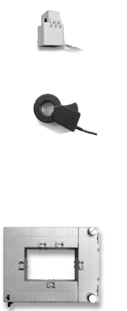
Optional Bus-Bar CT
• Six 50-Amp (black) sensors (3 pairs) for 208-Volt, 240-Volt or
480-Volt double pole or triple pole breakers.
• Sixteen 20-Amp sensors (8 pairs) used for monitoring single,
120-Volt or 277-Volt circuits, as well as double and triple pole
breakers in some cases.
For double or triple pole breakers, you must use the same size sensor on each breaker.
Monitoring 3-Phase Mains requires two 150-Amp spring loaded
sensors (connected together), and one single 150-Amp sensor.
(NOTE: As described below, at times each leg of a 3-phase circuit
will have multiple wires that will each requires a sensor.
Generally, installers should be provided with extra 150A sensors
as part of a Just-in-Case kit to address situations that were not
identified in advance, in order to be able to avoid a return visit).
If you end up with more of one type of sensor than you need and not enough of another, you
may use the extra 50-Amp sensors on smaller circuits and vice versa, although they may not
measure as accurately. (20-Amp CTs should measure accurately for up to a 30-Amp breaker; 50-
Amp CTs should provide good results for breaker sizes between 30A and 90A). For certain
larger loads you may need 150-Amp rather than the smaller CTs. As described later, it is
particularly important in this case to identify the size of
the sensors that you use on each circuit on your Channel
Setup Worksheet. An Authorized SiteSage Channel Partner
can provide additional sensors in the sizes required.
In some cases, 150-Amp CTs may be too small for the
Mains, or may not be able to be installed given the way the
Mains are configured. To address these situations, 300-
Amp, 600-Amp or 1,000-Amp bus-bar CTs can be ordered.
In other cases, you may have multiple smaller wires feeding
into each phase. In this case you can install CTs on each of
2 wires feeding the circuit. You will need to make sure the worksheet reflects this configuration,
which will also need to be reflected in the channel configuration portion of the registration
process.
Some commercial facilities have complex electrical installations with an Electrical Distribution
Center and multiple Main Panels. There are too many possible permutations of installation
configurations to describe here, but the basic installation process will generally be the same.
20A CTs
are white;
50A black
150A CT
© 2014 Powerhouse Dynamics, Inc. Page 13
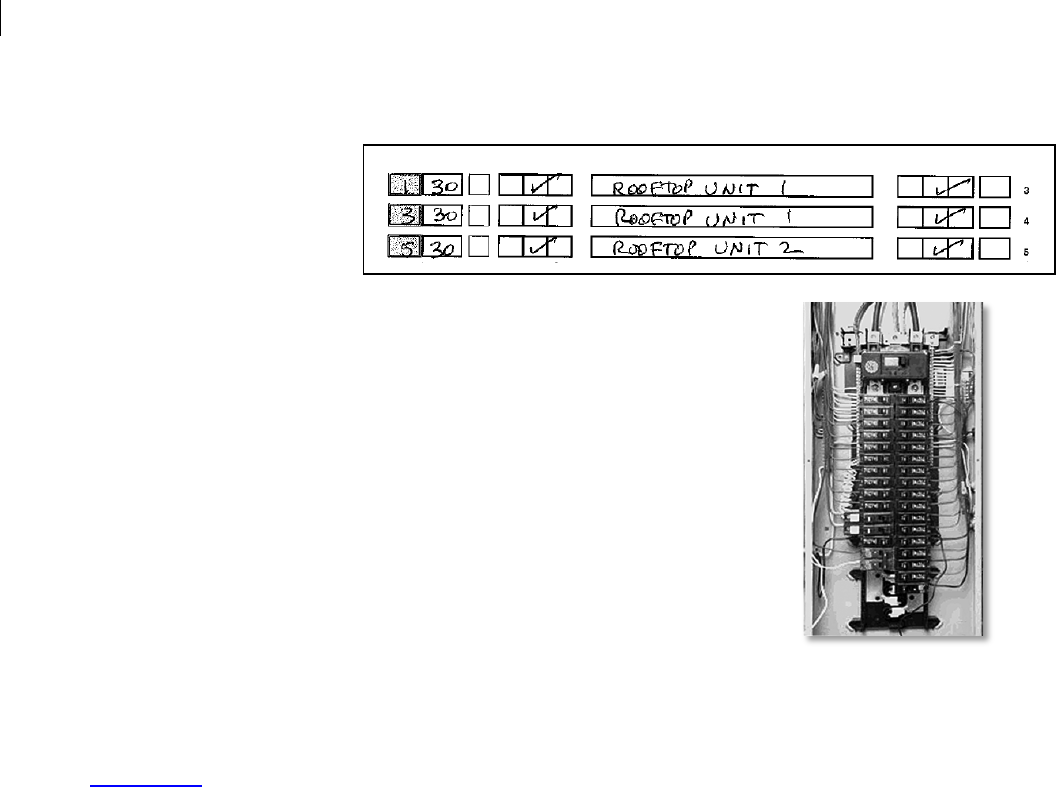
3.1 Channel Setup Worksheet
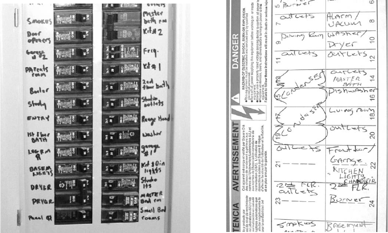
It is extremely important to accurately record which circuits are connected to which SiteSage
Channels, using the Channel Setup Worksheet included with each SiteSage Monitor unit.
(Note: there are usually labels associated with most if not all of the breakers, either on the
inside door of the panel or on the breakers themselves, but in some cases, labels will be
incorrect or missing. Since it is extremely important to know what is on the circuits being
monitored, before physically installing the SiteSage components it is suggested that the labels
on each circuit breaker be verified if at all possible. (Once SiteSage is installed and configured it
is possible to use the system to help identify miss-labeled circuits)).
The Channel Setup Worksheet should be filled out by the installer as the sensors are being
attached.
The form is divided into two sections. The upper section asks for general information;
specifically the following:
• Location address
• Serial # of the Energy Monitor (ePod) being installed, along with the Serial # of the
Gateway you are connecting it to. (The first 5 digits will be pre-filled)
• A description of the Circuit Panel to which the Energy Monitor is attached (e.g. “Main
Panel”)
© 2014 Powerhouse Dynamics, Inc. Page 14
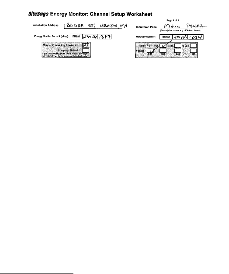
• Whether the electrical service is 3-Phase “Wye” configuration, 3-Phase “Delta”
configuration3, or single phase. For 3 Phase please indicate whether it is 480V, 208V or
240V service
• The number of the breaker used to power the Energy Monitor ePod
• An indication of whether SiteSage should “compute” the Main Power by adding all
branch circuits, which should only be checked when the Mains cannot be measured.
(This only needs to be checked once per location; not for every electric panel).
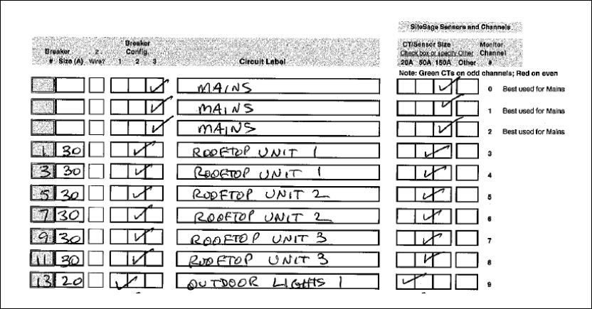
The next section has information on the breakers and circuits, as well as the Channels that they
are connected to. Page 1 allows you to enter information on up to 25 circuits. If you are
installing a SiteSage M-45 unit, you enter the remaining information on Page 2. In this section
of the Worksheet, please:
• Record the Breaker Number as it appears on the electrical panel4
• Enter the rated size of the circuit breaker, measured in amps
• Indicate if 2 wires are being monitored on this individual breaker, with 2 CTs
• Check if it is a single, double pole or triple pole breaker
• Enter the Circuit Label as it appears on the panel - or as most appropriate. (If there are
multiple labels that are the same, such as RTU or Walk-in Freezer, add some
3 3-Phase Delta configurations generally have no neutral wires and have a different voltage than the Wye (Y)
configuration, which is much more common in smaller facilities. Because the voltages can vary across the phases,
SiteSage may be slightly less accurate in a Delta configuration. It is not recommended to install SiteSage with
Delta High Leg B or Corner Grounded configurations.
4 Please make sure you correctly link the circuit with the Channel you connect the CT to. Generally, double and
triple pole breakers should connect to neighboring Channels, but if you need to connect them to Channels that are
not adjacent, make sure you reflect that on the Worksheet; you might want to draw a line that connects those
channels. Similarly, if you need to use 2 channels for a single phase of a 3-phase breaker (i.e. putting CTs on 2
wires for each pole), make sure the Worksheet shows that breaker number twice with the same label.
© 2014 Powerhouse Dynamics, Inc. Page 15
differentiation, even if it is as simple as RTU1, RTU2 etc. The system will automatically
append different numbers if you do not)
• Check the size of the sensor you used on the circuit. As described earlier, generally
place 20-Amp sensors on 120-Volt or 277-Volt single pole circuits and 50-Amp sensors
on 240-Volt or 480-Volt double pole circuits, but this may not always be the case given
the size of the breaker, or possible given your supply of sensors. In the case of any
circuit, if you used a CT larger than 20, 50, or 150-Amps, indicate the size of the CT you
installed.
There is also a “Notes” field on the second page to identify anything unusual.
Please note that the Worksheet is organized by SiteSage Energy Monitor Channel number,
starting with Channel 0. If you attach sensors to circuits in order, starting with the Mains
(which are best connected to Channels 0, 1, and 2) and continuing with circuits 1 then 3 etc., it
should be very straightforward to enter the information. (For panels with odd circuit numbers
on the left and even on the right, it makes sense to work down the left side of the panel first
and then go to the right side). If you cannot or do not follow this order, please be very careful
that you list the correct circuit that you connect to each Channel.
There are multiple copies of the Worksheet included, in case you make a mistake or want to
generate a neater copy. If you are not the person who will be entering this information online
during the registration and configuration process, please make sure the information is neat
and legible to someone else. Once the Worksheet is used for the Configuration part of
registration, a copy should be kept by the Authorized SiteSage Channel Partner for support
© 2014 Powerhouse Dynamics, Inc. Page 16
purposes.
We cannot overemphasize the importance of this Worksheet;
unless it is accurate,
SiteSage will be unable to deliver its full benefit.
3.2 Installing the SiteSage Energy Monitor Components
The following steps involve opening the circuit breaker panel and installing the sensors. It is
extremely dangerous for an untrained person to attempt this installation since high voltage is
always present in the panel. Injury or death could result from improper usage.
3.2.1 Preparing the Electrical Panel
WARNING – only a licensed electrician should
undertake this and all subsequent installation
steps, based on local codes.
1. Turn off power to the panel you are installing
2. Remove the cover from breaker panel.
3. Decide where you will mount the SiteSage ePod and xPods.
Typically there will be room at the bottom or sides of the
panel; make sure you can install with the Channels facing
out, so that you can connect the sensors.
3.2.2 Connecting the Power Cable
SiteSage is designed to be powered by a 15A or 20A breaker. It will probably be easier to install
the Power Cable before you connect all of the sensors. However, do not power up the Energy
Monitor ePod until all of the xPods have been fully installed and connected.
The Power Cable has black and white wires. Find an unused breaker, loosen the screw slightly,
slip the black wire under the washer that sits under the screw, and then tighten the screw so
NOTE: Best practice is to plan out the circuit-to-channel mapping before installing the
SiteSage Monitor components, and fill out all or portions of the Worksheets in advance. In
some cases this may have been be done by Powerhouse Dynamics or a SiteSage Authorized
Channel Partner. It is also best practice to put the supplied labels on the sensors, identifying
what channel they have been attached to, as well as on the wires near the channel
connectors on SiteSage ePods and xPods. This will make it much easier if there is ever a
need to change connections or replace a component.
© 2014 Powerhouse Dynamics, Inc. Page 17
the wire is held firmly. The white wire needs to be attached to the Neutral Bar. Find an empty
screw, loosen it, slide the white wire underneath, and tighten the screw.
NOTE: In many locations, the Electrical Code does not allow doubling up on a breaker or the
Neutral Bar.
Dealing with 480-Volt Power
The SiteSage Energy Monitor runs off 120-Volt power. If the electric panel in which you are
installing SiteSage has 480-Volt power, you need a small transformer (available from an
Authorized SiteSage Channel Partner), which converts 277V to 120V.
The transformer is mounted outside the circuit
panel. Use a knockout hole or drill a hole in the
panel to bring the 4 wires into the Panel. Attach
the (orange) wire labelled 120V to the black wire
of the ePod Power cable, and use a wire nut to
cover and tighten the connection.
Insert the wire labelled 277V (yellow and orange)
into a selected breaker.
Finally, attach the two yellow wires labelled Common and the white wire of SiteSage power
cable to the Neutral Bar.
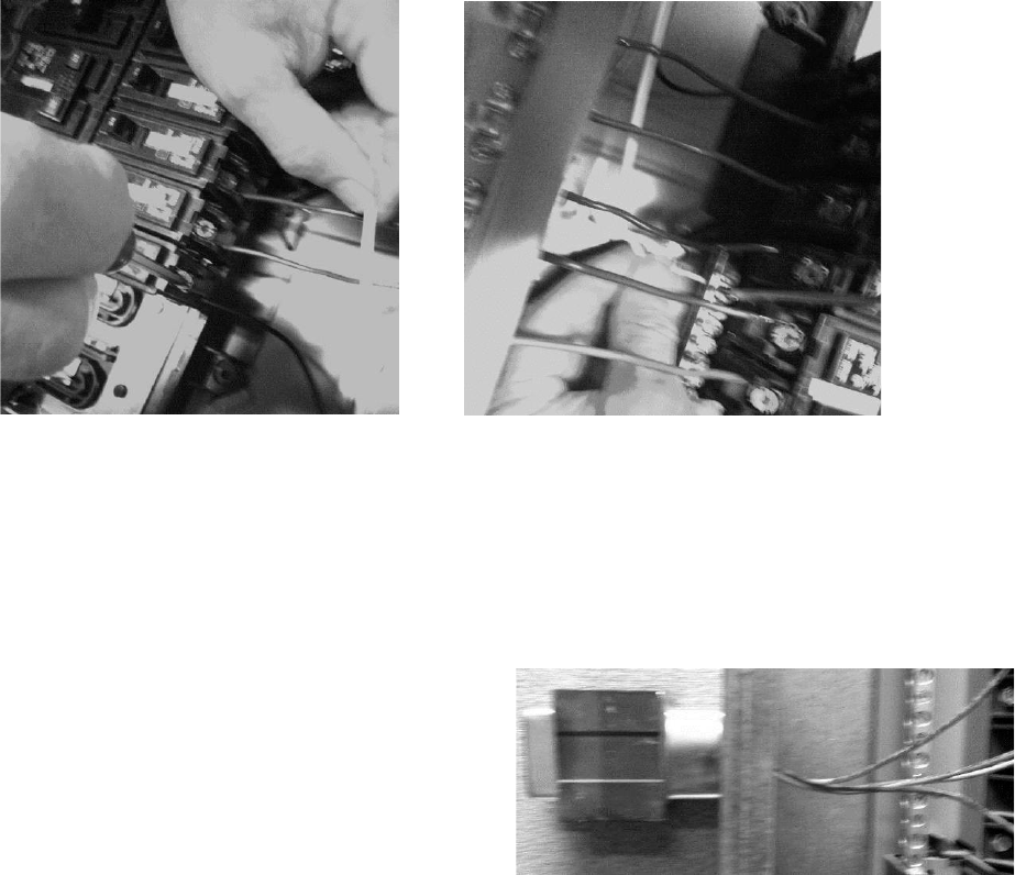
3.2.3 Sensor (CT) Installation
Unpack and unwind all of the sensor wires.
© 2014 Powerhouse Dynamics, Inc. Page 18
Installing Sensors on the Mains
If the electrical service is single phase, you will be
installing 2 sensors on the Mains; if it is 3-Phase, use 3
sensors.
If you are able to use the 150-Amp sensors, open the first
of the twin spring-loaded sensors by firmly pressing the
lever on the side, and place the open jaws around the
insulated area of one of the incoming power lines, above
where it connects to the panel. NOTE: In the case of 3-
Phase power, best practice is to install all sensors facing
the same direction. Most of the CTs have arrows; the
150-Amp sensors, however, do not. In this case, the label plays the role of an arrow, and
should face away from the breaker panel. Thus, for example, if the 150A CTs are installed on
breakers coming into the panel from above, as in the example to the left, the label should be
visible at the top. If the sensors are attached to the left of the panel, the labels should be on
the right; if installed to the right of the panel, they should be to the right.
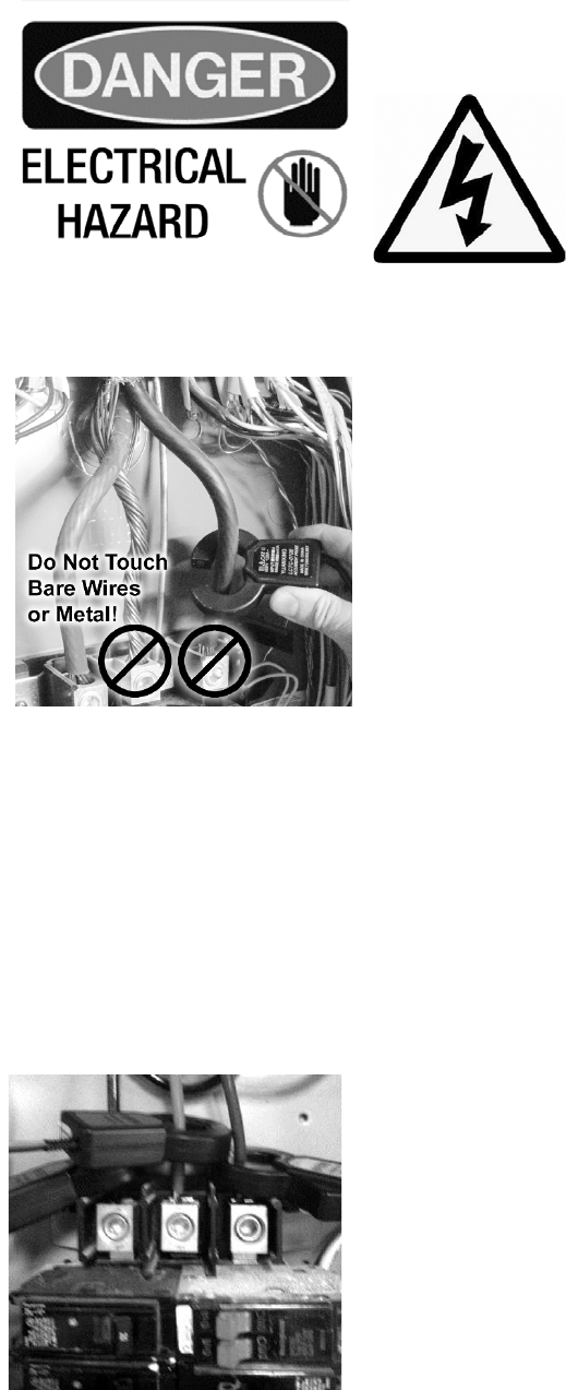
WARNING – even with the main breaker “off” these lines will still have power to them and
electrocution could result from touching the electrified areas. Make sure to avoid the
mounting screws as shown on the picture below.
Once the jaws are around the power wire, simply let go of
the lever and the sensor “ring” will close around the wire.
It’s normal for the sensor to slide down the wire and rest
close to the mounting screws.
Repeat this step for installing the second 150-Amp sensor
around the second incoming power line. For 3-Phase
power, take the individual 150-Amp CT and attach it to the
3rd incoming power line, as shown above.
© 2014 Powerhouse Dynamics, Inc. Page 19
It is best to connect these sensors to the SiteSage ePod now (as
described below), but you can wait until you have installed all of the
branch circuits as long as you have set up a way to identify which
circuit is connected to which Channel. It is best to use the supplied
labels. Place the one showing the Channel it is attached to on the
sensor itself, and the one showing the 2 Channel pairs on the wire
near the double Channels.
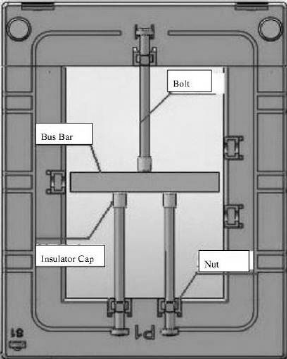
If you need the larger CTs, they attach a bit differently. There are
large screws you can easily remove by hand; pull the CT apart, place
around the circuit or on the bus-bar, and then close and reattach the
screws. The illustration to the right shows the installation on a bus
bar. These CTs have arrows.
NOTE: You can monitor more than one set of Mains on a single panel, or Mains coming out of a
distribution panel going to multiple panels. You can obtain additional CTs of any supported size
to accommodate additional Mains. To ensure that these CTs face the right direction in the case
of 3-Phase power, connect the provided Black Wire to the terminal of the CT marked S1
terminal. Connect the White Wire to the S2 terminal. With these CTs, the side marked P1
should face the breaker panel.
Installing Branch Circuit Sensors
With the main breaker still “off”, start installing the smaller sensors on each of the branch
circuits to be monitored. Please pay close attention to when to use a 50-Amp or 20-Amp
sensor, as described below. Start with the 12 circuits that will be attached to the SiteSage ePod.
When you have attached the sensors to the circuits and associated Channels, you can begin
installing the sensors that will be attached to the xPod(s).
For 3-Phase panels, install these sensors with the arrows facing the breakers. For simplicity,
for sensors installed on the left side of a panel, the closing clasp should be on top. For sensors
installed on the right hand side of a panel, the closing clasp should be in back.
120V Circuits
Many of the circuit breakers in the panel will be single pole 120-Volt breakers – or 277-Volt
breakers in the case of 480-Volt panels. Use one 20A sensor for each of these.
208V/480v circuits
Generally, use 50A sensors on double pole 208V or 480V breakers – but make sure to use the
same size for both poles.
© 2014 Powerhouse Dynamics, Inc. Page 20
On the Worksheet, please enter both circuit (breaker) numbers for a 208 or 480-Volt circuit, on
sequential rows.
For 3-Phase circuits, use 3 sensors (or 6 if you need to put sensors on 2 wires for each phase);
you can use 20A, 50A or 150A on each pole, depending upon the size of the breaker. You must
use the same size CT on each pole.
To install these sensors:
1. Open the sensor, squeezing the top (round part) and bottom of the sensor together to
relieve pressure on the latch, and then use your fingernail to disengage the latch. Do
not use a screwdriver or try to pry the latch open, since that could break the latch. Once
the pressure is relieved on the sensor it should be easy to open.
2. Place the open clamp around the insulated wire coming into the circuit breaker.
3. Close the sensor by pressing on the locking tab; you should hear a distinctive click; this
will confirm that the sensor is properly closed.
Try to orient the sensors so that their cables are out of the way as much as possible, and so that
the sensor wires are pointing to the sides of the panel.
The sensors may need to be staggered – alternating one closer to the breaker and one farther
away – in order to fit neatly in the breaker panel. This will often be the case when installing
sensors in narrow breaker panels.
Fill out the Channel Setup Worksheet as you install each sensor.
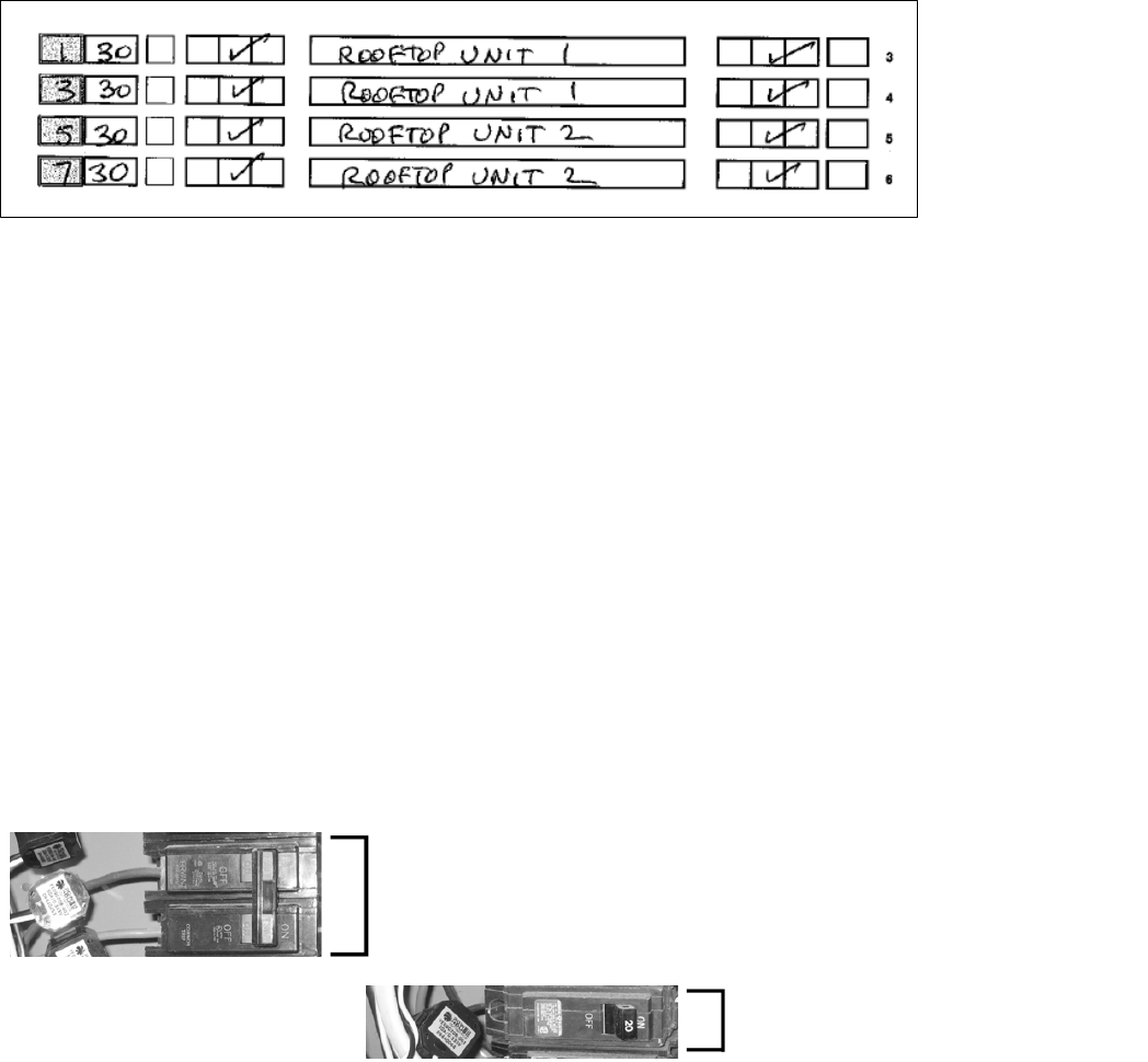
Double pole circuit (208V, 480V)
• Use two 50-Amp sensors
Single pole circuit (120V, 277V)
• Use one 20-Amp sensor
© 2014 Powerhouse Dynamics, Inc. Page 21
3.2.4 Optional PV Solar/Wind Turbine (or Other Generating Device) Monitoring
If the associated Software License includes renewables monitoring, SiteSage can also be used to
measure the power produced from an electricity-generating unit, such as a solar PV system or a
wind turbine. Any type of power generation brought into the electrical panel can be
monitored. (For non-renewable energy sources, such as a back-up generator, you do not need
to purchase the renewables license).
These power-generating units are generally installed on double
or triple breakers.
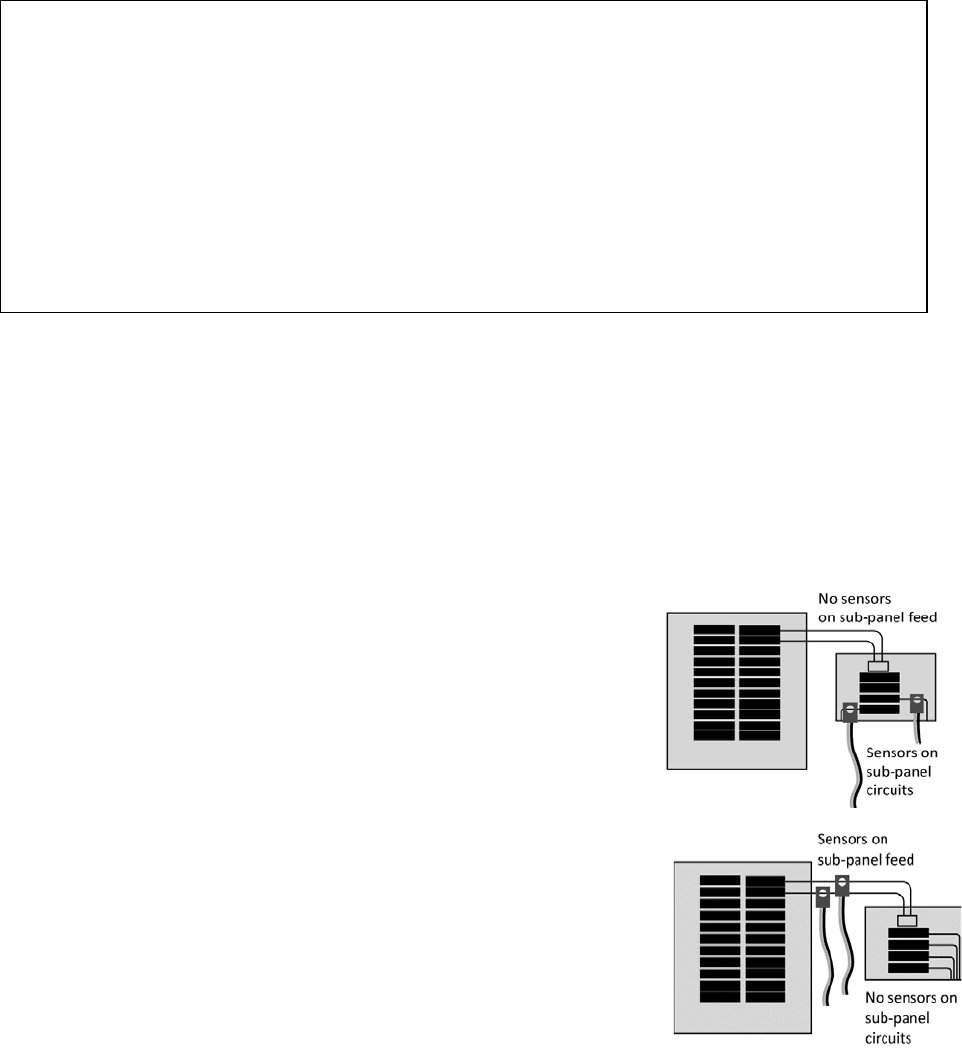
3.2.5 Installing a SiteSage Monitor in a Sub-Panel
If you are installing SiteSage Units at a Main Panel and one or
more sub-panels, the installation process is identical for each,
except that sub-panels will have no power inputs from the
electrical grid, but only from a Main Panel.
There is no need to attach sensors to the feed from the Main
Panel to a sub-panel if the Main Panel is being monitored. If
sub-panels are being monitored, do not put sensors on the Main
Panel circuits that feed the sub-panels. This would result in
double counting.
If you are not separately monitoring a sub-panel, then it does make sense to monitor the
circuits on the Main Panel feeding the sub-panel (see Figure to right), with 2 sensors.
NOTE: The best practice to follow to avoid later configuration problems is to install
sensors in an ordered and sequential manner. For example, with downward facing Mains,
attach the left most wire to Channel 0, the middle wire to Channel 1, and the right hand
wire to Channel 2. Then, for the most common panel type, start working your way down
the left breaker column, attaching breaker 1 to Channel 3, breaker 3 to Channel 4, breaker
5 to channel 5, etc. (skipping any breakers not being monitored). When you are finished
with the left column continue with the top of the right column (which generally starts with
breaker 2), and work your way down.
© 2014 Powerhouse Dynamics, Inc. Page 22
3.2.6 Connecting the Sensors to the ePod
As each set of 2 linked sensors (or single
150A or larger sensor) is installed, connect
the pair to the appropriately numbered
Channel port on the SiteSage ePod. The
sensor wire plug will lock in to a double
Channel port that is marked as a pair of
Channels. Check that the Channel port
connections match what is written on the
Channel Setup Worksheet. You can only
install the sensors such that the one with a
green label goes into an odd (left) numbered
Channel and the one with the red label (red for right) goes into an even (right) Channel in a pair.
(Again, the left and right Channel designations have nothing to do with the left and right
columns in the electric panel). A sensor wire plug is shown above. It is best practice to add a
label to each sensor wire that corresponds to the numbered Channel port on the SiteSage ePod
and xPods. This way if there is a need to replace a component, it is easy to figure out where the
sensors should plug in.
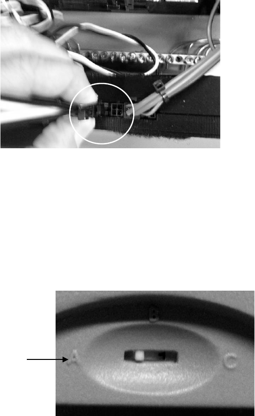
3.2.7 Connecting the Sensors to an xPod
Before connecting any Sensors to an xPod, make sure
the xPod switch is set correctly. The switch is needed to
be able to distinguish between xPods when there is
more than one. xPods should arrive with the switch set
to the A position. That is the correct position for the
first xPod you install. (There are no xPods required for a
SiteSage M-15). If a second xPod is installed, set the
switch to the B position; the third should be set to C.
Do not use the same switch position for multiple xPods.
The process for connecting the sensors to the Channels on the xPod is identical to the process
for connecting to the SiteSage ePod.
© 2014 Powerhouse Dynamics, Inc. Page 23
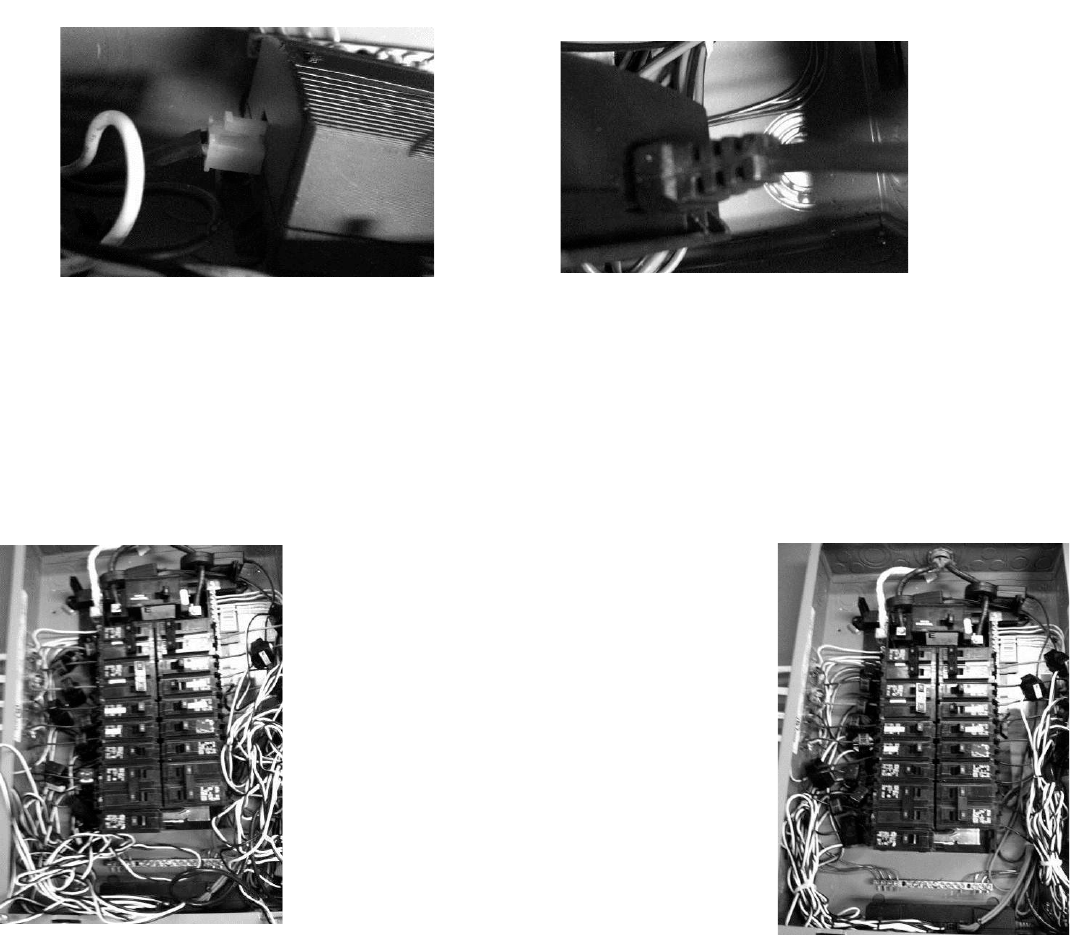
3.2.8 Connecting an xPod to the ePod and Mounting Them
The xPod has a cable coming out of one side. Connect the cable of the first xPod you install,
with the switch set to A, directly to the ePod. If you are installing 2 or more xPods, daisy-chain
them together, using the same cable.
Once you have connected all of the sensors, you can either leave the ePod and any xPods un-
tethered, or mount them inside the panel. You can use the tie wires provided and tie the Pods
to fixed spots in the panel, or use Velcro and attach to an inside surface of the panel.
Before mounting the ePod, connect the other end of the Power Cable to it, as shown below.
Make sure that the cable is tightly connected at both ends.
IMPORTANT: There is a serial number on the bottom of the SiteSage ePod. You should have
recorded this number on the Setup Worksheet, and it is needed to register and configure the
unit, so please make sure it has been recorded before you mount the ePod and close the panel.
3.2.9 Organizing the Sensor Wires
After all the sensors are installed at the
breakers and the wires are connected to the
Energy Monitor ePod and xPods, the set of
loose wires (up to 45) may look messy.
Organize the loose sensor wires on the left
and right side of the inside of the breaker
panel, using six or eight of the included wire
ties to prevent movement and allow the
cover to be affixed.
Power Cable attached to ePod
xPod attached to ePod
© 2014 Powerhouse Dynamics, Inc. Page 24
When you are finished, carefully cut the excess part of the wire ties with a wire cutter or strong
scissors.
You can now close the circuit panel and turn the Main power back on.
3.3 Installation of Other Sensors
The installation of other sensors is addressed in the Appendices of this Installation Guide.
© 2014 Powerhouse Dynamics, Inc. Page 25

4. Installing SiteSage Smart Thermostats
SiteSage currently supports two different smart thermostats, using 2 different communications
protocols: Z-Wave® and Wi-Fi®. These thermostats ship with installation instructions. In this
Section we cover the process of connecting the most commonly installed thermostat, which
uses Z-Wave; connecting the Wi-Fi thermostat is covered in Appendix B.
Getting a Z-Wave Thermostat on the local Z-Wave Network
Once the installer has finished installing a Z-Wave thermostat it can be turned on to control the
HVAC system locally. It is now ready to be connected to the Z-Wave network in order to have it
integrated with SiteSage. Please do not try to establish the temperature settings on the
thermostat itself; doing it through SiteSage is significantly simpler – and the SiteSage
temperature settings will override any settings established on the thermostat. (All mechanical
settings should be set on the thermostat).
STEP 1: get the SiteSage Gateway into “inclusion” mode:
a. Reset the Gateway. It will go through its normal reset cycle; the LINK and DATA lights will
flash 5 times (green if Wi-Fi, red if Ethernet) and then turn solid for 3 seconds. If there is a
Z-Wave radio, after 2 seconds these lights will blink orange very rapidly for 4 seconds. If
you hit Reset again while the lights are blinking orange, the Gateway will go through
another reset cycle, but this time the rapid blinking will be green. This indicates that the
Gateway has been placed into Inclusion mode for 3 minutes to enable you to enroll the
smart thermostats. The lights will continue to flash green throughout the inclusion period.
b. Alternatively, if SiteSage has already been registered at this location, you can accomplish
the same thing by going to https://sitesage.net, clicking on Settings/Smart Controls, and
pressing Add Z-Wave Control near the top of the page. Wait until the LINK and DATA lights
flash green which will indicate that the Gateway is in inclusion mode.
c. You can also put the Gateway into inclusion mode via the
embedded web server Z-Wave tab. (Press Configure,
then 4Add). If the Gateway is not yet on-line, open a
browser and enter http://169.254.1.1. (If you have a Wi-
Fi Gateway it creates an ad hoc Wi-Fi network; if you
have an Ethernet Gateway you can connect directly to
the network port on your computer). If your Gateway is
on-line, you can find the current IP address by going to sitesage.net/connect and entering
the middle 4 digits of the Gateway serial number.
© 2014 Powerhouse Dynamics, Inc. Page 26

STEP 2: enroll (or “include”) the thermostat in the Z-Wave network:
a. Press the MENU button on the smart thermostat
b. Press the NEXT button to advance to the Z-Wave menu
c. Press SELECT
d. Press YES to enroll in the network
STEP 3: verify that the thermostat has been enrolled in the network:
a. Press MENU on the main thermostat screen
b. Press the NEXT Button to advance to the About screen and press the Select Button
c. Press the NEXT Button to advance through the menu options to Node ID
• If the number listed there is anything other than “00”, the thermostat has been
successfully enrolled
• If the number listed there is “00”, the thermostat has NOT been successfully enrolled. In
this case, repeat Step 2 and verify again.
e. Press the DONE button twice when finished to go back to the Home screen
The thermostat needs to be in communications range with the Gateway in order to be included
in the network. If enrollment has failed, try moving the Gateway closer to the thermostat.
Once the thermostat has been enrolled you can move it back. After they are enrolled, the
thermostats can talk to each other, so as long as one of them is in range of the Gateway (and
the thermostats are in range of each other) they can reach the Gateway. Make sure to enroll
the thermostat closest to the Gateway first. If you are unable to include that thermostat, you
may need a Z-Wave range extender/repeater. This is a simple device that plugs into an outlet;
please consult with an Authorized SiteSage Channel Partner about getting a repeater. Locate it
between the Gateway and the closest thermostat. You will need to put the Gateway back into
Include range to include this device. In this case, just press the button on the range extender,
and a light will flash to show that the unit has been included. In some cases you may need to
© 2014 Powerhouse Dynamics, Inc. Page 27
install an additional Gateway to connect with a thermostat beyond the Z-Wave range extender
range.
Once a thermostat has been paired with a Gateway (or, more precisely, the snap-in Z-Wave
radio module), it will stay paired. If there is a need to change out the Gateway’s Z-Wave radio
module, you will first need to EXCLUDE the thermostat from the network. This is a similar
procedure to the one for Inclusion. (Note that you can use any Gateway to exclude a
thermostat; it does not need to be the one you included it with. Further, if you need to change
out a Gateway only but can use the same radio, there is no need for this process).
a. First you need to put the SiteSage Gateway into Exclusion mode. The easiest way to do
this is by going to the Facility View on the SiteSage Portal and then going to Settings/Smart
Controls and pressing Remove Z-Wave Control. Wait until the LINK and DATA lights flash
red to indicate Exclusion mode; the Gateway will stay in Exclusion mode for 3 minutes. You
can also do this in the embedded web server – pressing the Remove button on the
Thermostat tab.
b. If you do not have access to a computer, you can use the Reset function on the Gateway.
For this you need to put the Gateway back into Inclusion mode, exactly as outlined above.
When the DATA and LINK lights are blinking green rapidly for 4 seconds, press Reset again
(this will be 3 third time hitting Reset in this process). This time when the Gateway comes
out of the Reset process the lights will blink Red rapidly, indicating that the Gateway is in
Exclusion mode. It will stay in Exclusion mode for 3 minutes.
c. Next Exclude the thermostat from the network. Go to the thermostat menu as you did
before, and press NEXT to get to the Z-Wave menu, but this time you want to EXCLUDE the
thermostat. Once that is done you can include the thermostat with a new Gateway.
© 2014 Powerhouse Dynamics, Inc. Page 28
5. Registering and Configuring SiteSage
The next step in the process is Registration and Configuration, which is performed online. This
can be completed by the installer or by someone else, and is also described in the SiteSage User
Manual. Please note that until Registration and Configuration is complete, no data will be
stored and the SiteSage Portal cannot be accessed.
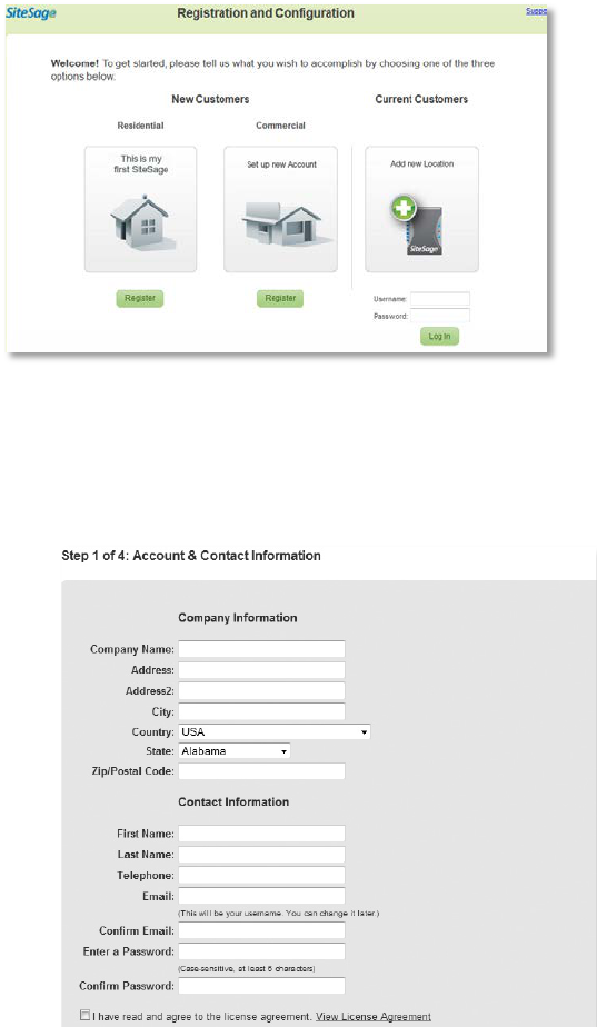
To begin the Registration and Configuration process, go to: http://Sitesage.net/setup
For the purpose of this manual, we are going
to assume a Commercial customer, since
most 3-phase electrical systems are in
commercial facilities. The process is very
similar for Residential customers, although
the pages are slightly different. If you are a
Residential customer and have trouble
following the instructions here, please check
out the SiteSage for Homes User Manual OR
the SiteSage for Homes Installation Guide at
http://docs.sitesage.net.
If this is the first SiteSage installation for this account, click Register, under Commercial. If
SiteSage is registered in at least one location and you are adding a system at another location,
log in under All Returning Customers with the
user name and password already established for
the account. If you are adding SiteSage
components to a location that already has
SiteSage installed and registered, there is no
need to go to Setup. Just log in to the SiteSage
Portal; the new components will be found and
you will be directed to a Wizard for
configuration.
Account and Location Registration
The process begins with setting up the Account.
© 2014 Powerhouse Dynamics, Inc. Page 29
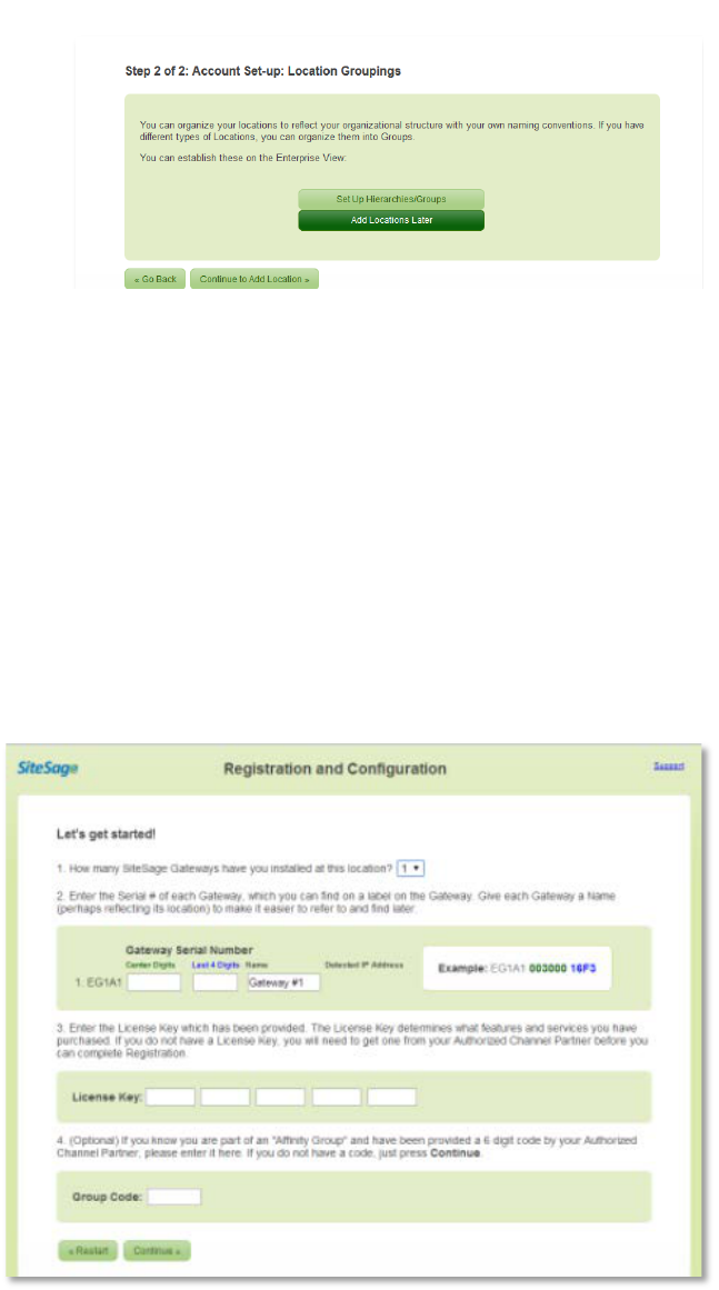
Step 1: Account and Contact Information
Enter basic information about the company as well as your contact information. (All fields are
required). If this is an existing account registering SiteSage at a new location, the account
information will already be filled out.
As part of setting up the Account, you
can also setup an organizational
structure here; for example if the
company is organized into regions
and sub-regions (using whatever
terminology the company uses for
these groupings). You can also group
locations on a non-geographic basis; for example, if you have multiple brands or very different
operating hours. Then, as you set up a new location, you can allocate the location to these
groupings. If you do not want to set the structure up now, this can also be done later in the
Enterprise View of the SiteSage Portal.
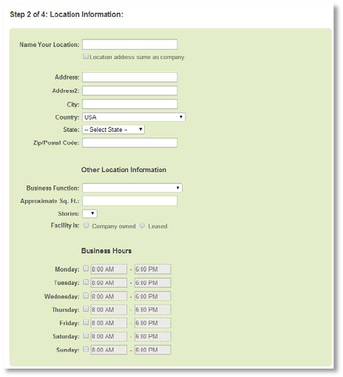
Step 2: Location-Related Information
The first part of this step involves provisioning the Gateways installed at the location, and
confirming the software license.
Enter the number of Gateways that you will be provisioning at this location. Then, enter the
middle 6 (you can skip leading
0’s) and last 4 digits of the
Serial # for each Gateway. You
can find these numbers on a
label on the Gateways. (Once
you enter the Serial #, the
Gateway’s IP address will be
returned; you can use this to
return to the Embedded Web
Server used for network
configuration if necessary).
Finally, enter the 25 digit
License Key provided by the
Authorized SiteSage Channel
Partner. The License Key
identifies what services have
© 2014 Powerhouse Dynamics, Inc. Page 30
been licensed, including whether this is a Residential or Commercial customer, the maximum
number of circuits to be monitored and controlled, and whether this location will be monitoring
renewable generation sources or gas or water. If you have not been provided a License Key,
please contact the Authorized SiteSage Channel Partner. You will not be able to register
SiteSage without a valid License Key.
NOTE: If you see a “Not Valid” notice after you press Continue, it means you have entered a
non-valid Device ID. Please re-check the numbers you entered and try again. In the unlikely
event the number is still not valid, and you’re sure you have entered it correctly, please contact
Powerhouse Dynamics or the Authorized SiteSage Channel Partner.
Once you have entered the License Key, click Continue and you will be taken to a page that
confirms the services that have been licensed. If this is not consistent with your expectations,
double check the number you entered and, if it is correct but does not show what you
expected, please contact your Authorized
SiteSage Channel Partner.
Press Continue and you will be asked fill out
some information about the facility in which
SiteSage is being installed. This includes
providing a name that can be used to refer to the
location (e.g. Center St. Store). Enter the address
(if it is the same as the corporate address you
can copy that over), as well as some information
about the function and size of the building, which
is helpful for analysis purposes. Please also enter
the hours of operation of the location for each
day. (If you created an organizational structure,
you will be asked to which grouping(s) this
facility belongs).
Step 3: Utility Rates
Next, confirm the electric utility company for the facility. SiteSage has a database that identifies
the utility based on zip code, but some zip codes are served by more than one utility, so you
may need to choose one from the list. If SiteSage cannot locate your utility, use the state list to
select it.
© 2014 Powerhouse Dynamics, Inc. Page 31
A Note on Utility Rates: The SiteSage database reports average commercial rates for each
utility. This works extremely well in getting a sense of the costs of different pieces of
equipment in the facility. However, the cost estimates generated by SiteSage do not reflect
actual utility rate calculations, which can be complex for some commercial facilities. In
addition, SiteSage’s measuring period will not be the same as the billing period reflected on
utility bills, so trying to compare them is not recommended.
The SiteSage database also maintains average
commercial rates for every utility. You can
accept that rate or, if you feel it does not
accurately reflect the charges at this facility
either calculate it from a recent bill or enter a
rate directly.
There is also a section where you can enter a
Demand Rate. Demand Rates, which are
based on the peak energy usage during a
month, are very common for commercial
utility customers.
SiteSage can help better manage Demand
Rates, so please make sure to enter the
requested information if this facility is on a
Demand Rate. Also, indicate if you know
whether this location is assessed a Power Factor penalty charge for low Power Factor.
At this point you are given the option to finish the registration session or continue with system
configuration. If you end the session now, you will be able to come back and complete
configuration at a later point.
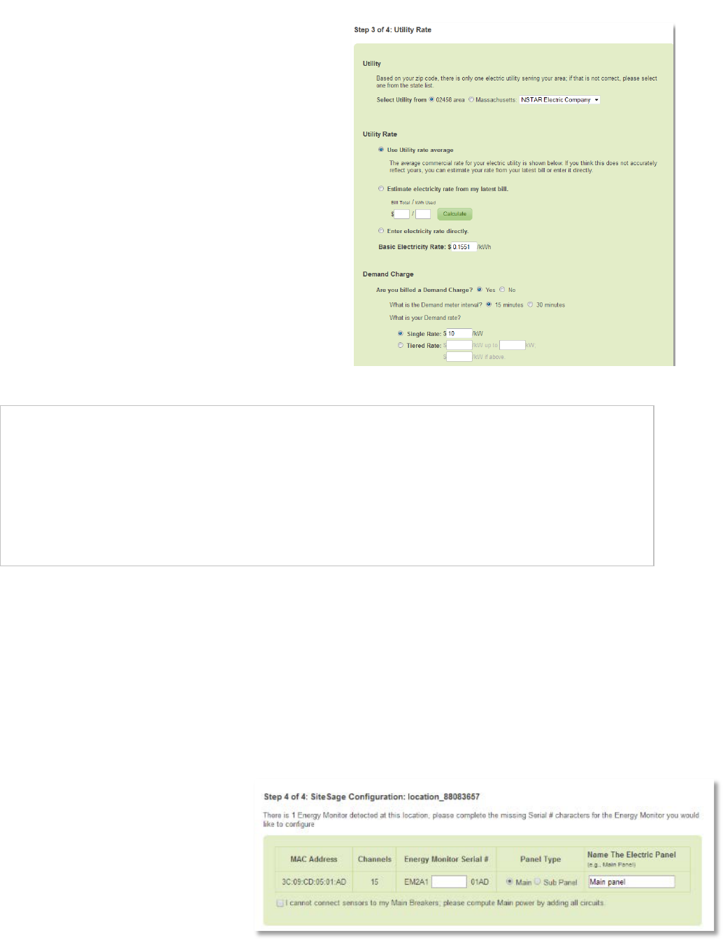
Step 4: Energy Monitor Channel Configuration
SiteSage needs to be configured so that the system knows what is being monitored on each
SiteSage Energy Monitor Channel. This is a critical step in ensuring that SiteSage delivers true
value. Enter information from the
completed Channel Setup
Worksheet(s), described earlier.
To start this process, you will see
a list of SiteSage Energy Monitors
that the Gateways have
identified. To make sure that only
© 2014 Powerhouse Dynamics, Inc. Page 32
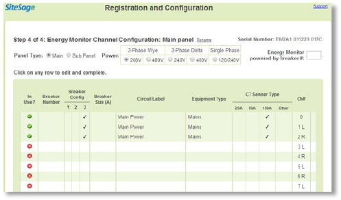
panels expected are being monitored, please enter the missing 6 digits of the SiteSage Monitor
serial numbers. This number appears on the back of the SiteSage Energy Monitor ePod, and
should have been entered onto the Channel Setup Worksheet. Enter a descriptive name for the
electric panel, such as Main Panel, Kitchen Panel, etc. (This should also appear on the Setup
Worksheet, and you can change it at any time).
If a SiteSage Energy Monitor you expected to see has not been listed, it is possible that the
Gateway has been located too far from that unit. Try moving the Gateway and see if that helps.
If you have multiple SiteSage Monitor units located far apart (say on different floors), you might
need to add another Gateway. You can complete Configuration for any Site Sage Energy
Monitors that have been found now. (If you add a Gateway later you do not need to come back
to Registration. You will then be able to go to the Channels Configuration tab in Settings on the
SiteSage Portal and click on Gateway Assignment, and then Add a Gateway. You can then enter
the Gateway serial number, much as you did earlier. If it finds a new SiteSage Monitor you will
then be able to configure it).
If the Computed Mains box has been checked on one of the Worksheets because the installer
was unable to install sensors on the Mains, please check the box on this page. This will tell
SiteSage to sum the branch circuits to estimate the facility totals.
When you hit Continue you will be taken to a page where you can capture the information
from the Channel Setup Worksheet the installer filled out. Make sure you enter the number of
the Breaker that is powering the SiteSage ePod, since that will be needed if there is ever a need
to power cycle the unit.
The electric service will default to 3-Phase 208V, since that is the most common configuration
in small commercial facilities. If that is not what you have, you can re-set to either3-Phase Wye
480V, 3-Phase Delta 240V or 480V, or Single
Phase 120V. The page will change slightly if you
switch to Single Phase. (NOTE: This is a critically
important setting for the purpose of
calculations, so please make sure to select the
correct electricity service before continuing).
© 2014 Powerhouse Dynamics, Inc. Page 33
For a 3-Phase Main panel, the Mains should have been connected to Channels 0-2. Make sure
that the correct CT size has been selected. (You can connect Mains to other channels as well).
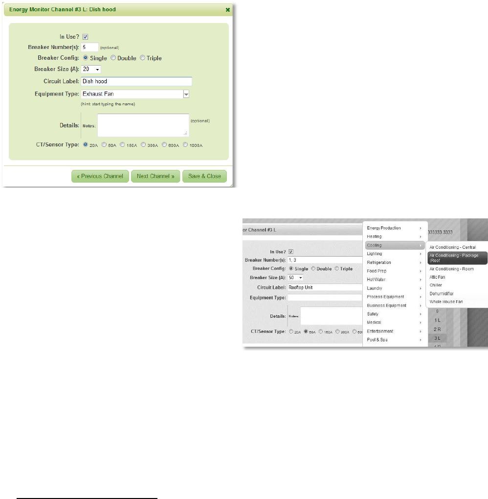
Then, click on the row for Channel 3 and it
will bring up a data entry form where you can
quickly enter the necessary information for
that Channel. Set the Channel to In Use to
begin to enter data on the form.
For other than Mains, please enter the
Breaker Number, which will appear on the
Worksheet, and select the Breaker Size in
amps, from a pull down list. Next indicate
the Breaker Configuration: e.g. whether it is
a single, double or triple pole breaker.5 Enter
the Circuit Label that appears on the
Worksheet, or feel free to modify it.
You need to enter some additional
information that is not on the Worksheet
about equipment on each circuit. Most
importantly, you will be asked to enter the
major Equipment Type on each circuit. In
many cases the equipment type is obvious
from the circuit label. In other cases, for
example, if the label says “Kitchen
Appliances”, you might need to make a
judgement call about the primary equipment. (You can type in the Equipment Type box, but it
will only recognize items included in the pull down list. The same is true for other fields). This
field is extremely important to complete accurately, since most analyses are driven by
Equipment Type.
You can enter some optional Details about a piece of equipment, which may include make,
model, and year installed, or just text. This information will appear on the Circuits page view,
and may help SiteSage analyze equipment usage.
5 The system will default to assume that you have connected 3 CTs to a triple pole breaker (and 2 to a double pole
breaker), and that the channels you used are sequential. If 6 CTs were used because of wire size, select Double
Wire. If you needed to install on channels that were not sequential, please select Non Sequential Channels and
identify the 2 (or 5) additional channels you used. Once you move to the next channel, the form will re-order the
rows (keeping the channel numbers the same) so that the 3 channels for a single triple pole circuit are on
successive rows.
© 2014 Powerhouse Dynamics, Inc. Page 34

Based on Breaker Size and Equipment
Type, the system will automatically
make an assumption about the
CT/Sensor configuration. Change this if
it does not match the Worksheet.
You can find a description of each field
by holding your mouse over the heading
on any column on the page.
Once you have entered all of the
information about a Channel, press
Next Channel to go to the next one, and so on until you have entered all of the information on
the Worksheet. (If you hit Save, the data will be saved and the data entry box will close; you
will need to click on another row to begin entering data again). Note that you can edit any
Channel data already entered by clicking on the associated row.
NOTE: If there were empty circuit breakers slots in the circuit panel and a Channel was skipped
during the installation, please make sure you do not enter any information for the skipped
Channel, and make sure the In Use box is not checked.
If you are configuring Channels for more than one SiteSage Energy Monitor, when you
complete this page for the first unit and hit Continue you will get a new empty form to
complete for the next unit. If for some reason you cannot finish channel configuration in one
session, you will be able to complete registration as soon as you have configured one SiteSage
Monitor, and then later log onto SiteSage Portal (Settings/Channels) to configure additional
SiteSage Energy Monitor units.
Once you have filled out the configuration for each unit that has been installed,
click Finish, and you’re ready to use the Energy Monitor! Unless.....
If the Software License provides support for renewable energy and have configured a power
source, such as PV or Wind, you will be prompted to do one last step, which involves verifying
the direction of all power inputs, including the Mains. (If your production is greater than your
usage, you can actually be shipping power back into the utility grid - or net metering).
There is a 2-step process to Power Direction Calibration. First, turn off the breaker the Power
Inputs are coming into (typically one or more inverters). In that way, SiteSage can be confident
that Main power is incoming.
© 2014 Powerhouse Dynamics, Inc. Page 35
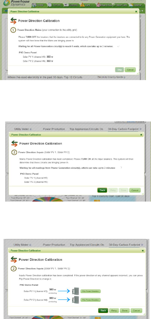
Once the system verifies the direction of the Mains you will be prompted to turn the Power
Input breakers back on so that their direction can be calibrated.
The system will then confirm when calibration has been completed. If for any reason the
system has not determined the correct power direction – for example if you are calibrating PV
at night when it is not generating any power, press the “Flip” button and it will adjust.
And, now you have fully completed configuration of the Energy Monitor and can move on to
other components like thermostats.
© 2014 Powerhouse Dynamics, Inc. Page 36
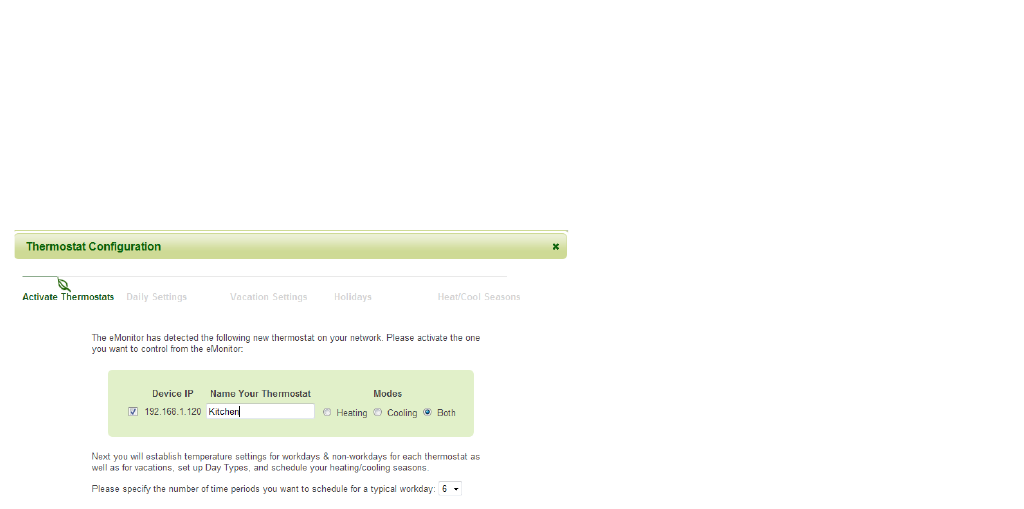
Step 5: Configuring a Smart Thermostat
Please note that the configuration process is the same for both Z-Wave and Wi-Fi thermostats.
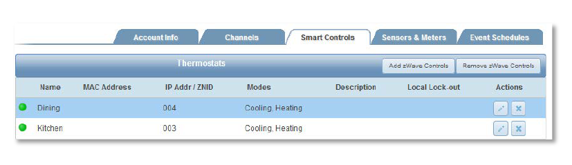
Once you have gotten one or more Smart Thermostat connected, log into SiteSage Portal, you
should see a pop-up indicating new Smart Thermostats have been found; if not go to
Settings/Smart Controls and click Add Z-Wave Control (Find New Controls for Wi-Fi). A dialog
will pop-up telling you the system is scanning for smart controls. If it finds a Smart Thermostat
it will identify it. You can then hit Configure Controls, which
will pop-up a page like the one below, which is the start of a
Wizard that will let you quickly configure the Thermostat.
(SiteSage will keep scanning for thermostats even if you
close the dialog and go to another page. If it finds one, the
Wizard will pop-up as soon as you go to the Home page).
NOTE: if Enterprise level controls
have been set up for this account
you will be able to pull down pre-
established settings, or Templates
(including possibly a Default
Template specifically set for this
facility) and not need to go through
the Wizard. In addition, there is a
generic default template that can be
applied at this point as well; it is
always possible to come back and update thermostat settings at a later point.
Select the thermostat(s) you want to configure, give them a name (e.g. Kitchen), indicate
whether they are used for Heating, Cooling, or Both, select the number of time periods that you
want to be able to program (4, 6, or 8) and press Continue. If you have selected more than one
thermostat, the Wizard will take you through each one sequentially.
You will first establish the daily temperature settings for each Smart Thermostat.
• The SiteSage Smart Thermostat lets you create different settings for different days of
the week and also create a setting for days you are closed.
© 2014 Powerhouse Dynamics, Inc. Page 37
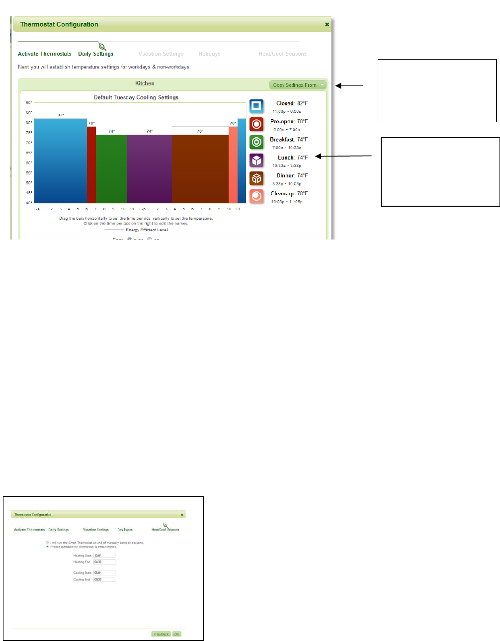
• SiteSage uses a unique, graphical interface to make it simple to adjust temperature
settings. Just grab the edge of a colored bar by clicking on it and drag it horizontally to
change the Time Period - or vertically to change the temperature. It’s that simple!
• To name the periods, place the mouse over the name on the right hand side of the page;
this creates a box you can use to edit the text. Whatever you select will be used from
now on.
• The Wizard will walk you through each day. You can copy the settings from any
previous day.
• The Wizard addresses both Heating and Cooling Settings, if you have both, which work
exactly the same way, EXCEPT that the default settings are vastly different.
If you have more than 1 thermostat and want them set exactly the same, SiteSage will let you
“clone” the previous settings so that you do not have to enter them again.
Once you have created the Heating and Cooling
settings for Work Days, you are next asked to
establish settings for days the facility is closed, which
would include holidays. For these days, a single
temperature setting for Heat and one for Cool is all
you need.
Finally, you can either tell SiteSage that you want to
manually change from Heating to Cooling Season, or
schedule it to happen on specific date or
automatically switch.
You can copy the settings
from one day to another &
not have to re-enter them
Click on any of the period
names and you will see a
field where you can enter
your own names
© 2014 Powerhouse Dynamics, Inc. Page 38

Setting up Additional Thermostats
Once you have already set up a Thermostat, if you install another one at a later time, please go
to the Settings/Smart Control tab and click (Find Z-Wave (or New) Controls in the top right
hand corner to find the new Thermostat.
Enterprise Level Controls
Control Templates can be created in the Enterprise View to be pulled down to when a
thermostat is added (or pushed down at other times). This is described in the SiteSage User
Manual which can be found at http://docs.sitesage.net or via the Support link on the SiteSage
Portal.
© 2014 Powerhouse Dynamics, Inc. Page 39
Appendix A: Frequently Asked Questions
What if there are not enough sensors to monitor all circuits in a panel?
Unless you want to upgrade the SiteSage Monitor to a larger configuration with more sensors
or add another SiteSage monitoring unit in another electric panel, your best choice is to select
the circuits to monitor, based on what you expect to be the major power users, or circuits with
the most important equipment. You can upgrade or add additional units at any time.
Does it matter which way I orient the CT sensors?
For single phase power it does not, but for 3-phase it is best practice to orient them the same.
In that case, all of the sensors should be installed with the arrows pointing towards the
breakers. (In the case of 150-amp CTS, there is no arrow, but there is a label; assume the arrow
faces left to right on the label). This is actually fairly straightforward, since it implies that all of
the sensors on 1 side of the panel should line up the same way. In the case of 20 and 50-A CTs,
this would mean the clasp should be on top and showing on the left side of the panel, and
underneath and not showing on the right side.
What if I cannot fit all the sensor wires in a circuit panel?
If most of the wires fit, we suggest you prioritize circuits and only monitor the number of
circuits that fit. (You may decide you need a SiteSage monitoring unit that supports fewer
circuits).
What if the Main wires are too big for, have much higher amperage, or cannot accommodate
the 150A sensors? Check with your Authorized SiteSage Channel Partner about getting 300A,
600A or 1,000A sensors. (NOTE: the 300A and 600A sensors are the same size; the 1,000A
sensors are slightly larger). If there is no way to monitor the Mains but you can monitor all
branch circuits, selecting the Computed Main option during registration will tell the system to
add up all branch circuits to compute total power.
What if there are too many 50-Amp sensors and not enough 20-Amp sensors?
You may use the 50-Amp sensors on circuits with smaller amp ratings – and vice versa – as long
as you indicate the actual sensor size used on the circuit. There will be some loss of accuracy,
but generally 20A CTs will work fine on breakers up to 30A, and 50A sensors will work well on
breakers from 30A-90A. Speak to your Authorized SiteSage Channel Partner about getting
additional sensors of the size you are missing.
Does SiteSage support 1,000-Amp electrical service?
Yes. SiteSage can support 1,000-amp, as well as larger, electrical services.
© 2014 Powerhouse Dynamics, Inc. Page 40
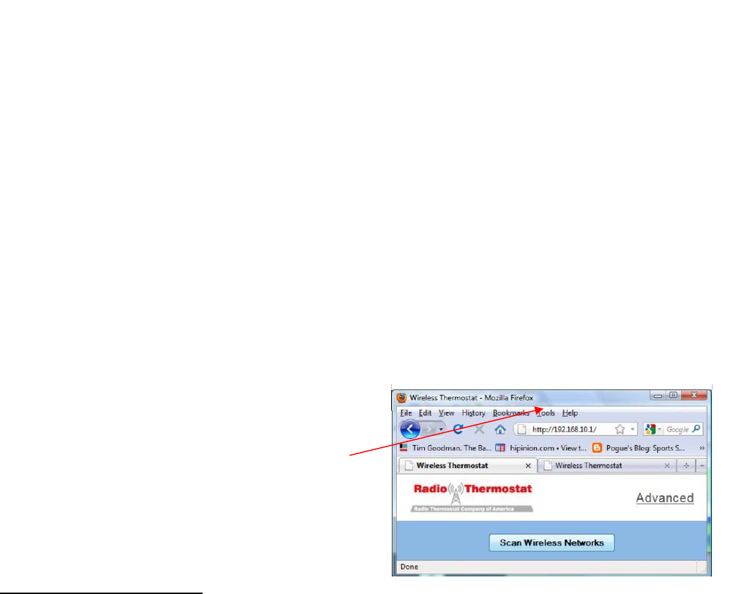
Appendix B: Provisioning a Wi-Fi Smart Thermostat
Getting a Wi-Fi Thermostat on the Network
Once the installer has finished installing a Wi-Fi thermostat it will turn on and control the HVAC system
locally. It is now ready to be connected it to the Wi-Fi network. The Yellow LED will be blinking
indicating that the thermostat is ready to be configured. Please do not try to establish settings the
thermostat itself; doing it through SiteSage is significantly simpler – and SiteSage settings will override
any settings done on the thermostat.
STEP 1
On a PC, Mac, smart phone, or other device6 find the
list of available networks. When the thermostat first
turns on it will temporarily create its own network. Its
network name will start with the word thermostat,
followed by six letters or numbers. Find the
Thermostat’s Wi-Fi network and connect to it. (If you
do not see the network information, hit Menu on the
thermostat itself, then Network Select and then Mate.
You will see a solid yellow light to the left of the display
when the network is broadcasting).
If your computer displays an unsecured network
message, click “Connect Anyway” and continue
connecting to the thermostat. If the connection was
successful, Successfully connected to thermostat xx-yy-zz will be displayed.
If you are unable to connect to the thermostat, try clicking
on “Connect To” again.
STEP 2
Open a web browser and enter the address
http://192.168.10.1. The page to the right will load. For
the most common setups (particularly those with dynamic
IP addresses) click “Scan Wireless Networks”. This will tell
the thermostat to look for your wireless network.
6 As noted earlier in the document Android and Windows 8.1 do not directly support ad hoc networks and you will
need to find a utility that allows you to use these operating systems for this purpose.
© 2014 Powerhouse Dynamics, Inc. Page 41
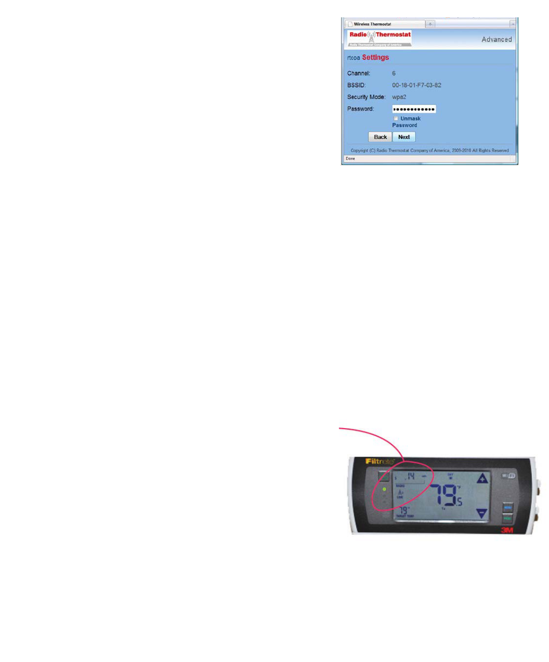
After a few moments you will see a list of available wireless networks displayed in the window. Click on
the intended network to join.
STEP 3
If the wireless network is password protected, use this screen to
enter the Password and press Next.
For security purposes all data transmitted over Wi-Fi is encrypted
with industry proven security methods. This ensures that nobody
else can gain access to the thermostat during this configuration
process.
Next, find the thermostat’s PIN at the top left hand corner of the
thermostat. Enter this PIN into the Pin: text box. [In this example the PIN is
44911). Then, click Set Network to proceed.
STEP 4
The Wi-Fi thermostat will now attempt to join the network. If this is
successful, the green light on the thermostat will start to blink, and
the word “link” will appear on the thermostat screen. In addition, the
last three digits of the thermostat’s IP address will be displayed in the
top left hand corner of the screen. In this case the IP address of the
thermostat is 192.168.1.14. You can see the “14” on the screen.
The PROVISIONING DONE screen will display in the browser.
It also shows details about the configuration of the Wi-Fi
module; something like:
© 2014 Powerhouse Dynamics, Inc. Page 42
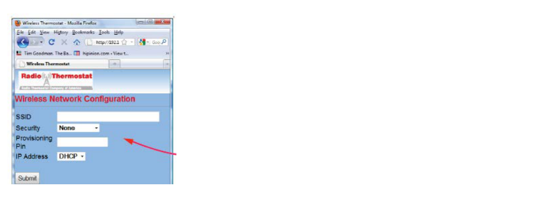
SSID: Wednesday’s
BSSID: 00-18-01-F7-03-82
Security: wpa2
IP: Dynamic
If there is an error in the setup process the red light will flash. This many happen because you did not
enter the security password correctly, or the connection was momentarily lost. After a few minutes the
thermostat will return to its Ready to Connect state with the yellow light showing solid. Please try again
and repeat from STEP 1.
STEP 5
When the Provisioning
process is completed
successfully, connect your
computer back to the
network so you can proceed
with the Thermostat
configuration process.
Using the Advanced tab
If you want to set the
parameters of your network manually – for example to set a static
IP address - use the Wi-Fi setup ADVANCED tab. To use this tab,
click it and input the parameters. Click Submit to return to the previous page.
© 2014 Powerhouse Dynamics, Inc. Page 43
Appendix C: SiteSage Networking Requirements
SiteSage Energy Monitor units that are installed inside electrical panels in a facility
communicate via a wireless radio to the SiteSage Gateway. The radios have a range of at least
30 feet and do not require line of sight. The Gateway needs to be connected to a facility
network in order to access the Internet to upload data to the SiteSage cloud-based servers.
Depending upon the location of the electrical panels, it is conceivable that there will need to be
more than one Gateway installed.
The SiteSage Gateway is a “headless” device which can be connected through hardwired
Ethernet or Wi-Fi (B or G only). It only requires Port 80 to be open, and only makes outgoing
HTTP requests to the SiteSage servers. There is no way to communicate with the Gateway from
the Internet, other than through the responses to the HTTP request.
Ethernet Connection (the clear preference is to use Ethernet wherever possible in order to
maximize reliability).
Normally, the SiteSage Gateway requires DHCP in order to connect to the network. If DHCP is
not used in the facility, a static IP address can be provisioned, but the Gateway must first be
attached to the network using DHCP. If a DHCP server is not available in the facility, it is
possible to provision the system on another network that has DHCP and then move it to the
destination network. The system can connect to an HTTP proxy server; to configure for a proxy
server we will need to know the IP address or URL and port number.
If a static IP address is required, we will need to know, in advance, the following information:
• IP Address
• Network Mask
• Gateway IP Address
• DNS Server IP Address
• DNS Server2 IP Address (Optional)
If MAC level filtering is enabled on the network we can provide the Ethernet MAC address in
advance, if required. If there is a restriction to a specific port, we will need to know which port
on the switch to attach to. (In the event that the Gateway is not connecting directly to the
switch, we will need to coordinate on the installation).
Wi-Fi Connection
If Wi-Fi is required, the preference is a secured connection. The Gateway needs to be
connected to a network that is up 24 X 7 and does not limit users’ connection time. Because
the system is headless, there is no way to accept terms or respond to a prompt. If the standard
public network in the facility has any such restrictions that can be overridden, the Wi-Fi MAC
address can be provided in advance to allow the system to be pre-provisioned.
© 2014 Powerhouse Dynamics, Inc. Page 44
The system supports both WEP and WPA security. In a Wi-Fi configuration, the following
information is required:
• SSID (Name and whether or not it is broadcast)
• Encryption Type (WEP/WPA/WPA2/etc.)
• Encryption Key/Pass Phrase (NOTE: if these are regularly changed, please provide
notification in advance of the new key, along with the planned date and time of
change, on an ongoing basis).
The system can also support a static IP address on a Wi-Fi network; in this case the system can
be provisioned locally even where no DHCP server is available. The same information as
requested above for an Ethernet connection is required. If a proxy service is used, the IP
address or URL and port number must be provided.
NOTE: The optional Wi-Fi smart thermostat does not have an Ethernet option. Peer-to-peer
access must be enabled for SiteSage to be able to connect to the Wi-Fi thermostat. If the
Gateway is sharing a public Wi-Fi network, where peer-to-peer access is not advisable, please
set up a separate SSID for SiteSage Gateway. The SiteSage Z-Wave thermostat connects
directly to the Gateway and requires no access to the facility network.
For each facility in which SiteSage will be installed, please answer the questions on the
following page in order to facilitate the network installation process.
© 2014 Powerhouse Dynamics, Inc. Page 45

SiteSage Networking Questionnaire
Company: ____________________________ Facility Name/Location: _______________________________
Preferred Network Connection: Ethernet ____ Wi-Fi ____
If Wi-Fi: SSID _____________________ Broadcast? Yes ___ No ___
Encryption Type ___________
Pass Phrase ________________________________
Do you regularly change the Password? Yes ___ No ___
Peer to Peer Access Enabled? Yes ___ No ___
Do you have a DHCP Server Available? Yes ___ No ___
Static IP Address Required? Yes ___ No ___
If so: IP Address ____________________________________
Network Mask ________________________________
Gateway IP Address ____________________________
DNS Server IP Address __________________________
DNS Server2 IP Address _________________________ (optional)
If a Proxy Server is used: IP Address/URL ____________________________ Port #: _____
De we need to provide the MAC address(es) in advance of installation? Yes ___ No ___
Do you apply content filtering on your network? If so, we need to provide Yes ___ No ___
you with content samples so that you can configure such that our data will not be caught in the filter.
IT Support Contact Information:
Name: ____________________________
Phone: ______________________
e-Mail Address: ___________________________
© 2014 Powerhouse Dynamics, Inc. Page 46

Appendix D: Installing Temperature Sensors
SiteSage supports temperature monitoring. It currently utilizes the 1-Wire protocol for bringing
wired sensor data into the system. (Wireless sensors will be supported in a future release).
These sensors can be installed inside refrigeration units, in various parts of an HVAC or Make-
up-Air unit, and at other locations where temperature readings are important, or be used to
monitor air temperature. Each Gateway can support up to 50 sensors.
Specifications
Waterproof
.5 degree resolution
Temperature range: -55 *C ~ +125 *C
No external components: single-bus interface
Labels with sensor IDs provided to simplify provisioning
Output leads: red (PWR), blue (DATA), black (GND)
For non-powered operations with SiteSage, only 2 wires are needed to connect to the
Gateway - combine red (PWR) and black (GND) wires
Installation
The sensors can be installed by
anyone licensed to do low voltage
wiring. Wires from different sensors
can be spliced together, so it is not
necessary to have a full wire run for
each sensor. This sensor does not
require any external power (other
than the Gateway). The wire should
be connected to Port D3 on the
Gateway; the DATA wire goes into
D3+ (on the left) and the combined
PWR/GND goes into D3-.
Connecting wires should be provided by the installer. Use thermostat cable or other 24-gauge
hook up wire (#20-26 AWG). It should be possible to install very thin wire through the gasket of
a refrigerator or freezer to avoid having to drill a hole.
© 2014 Powerhouse Dynamics, Inc. Page 47
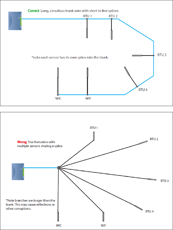
Stringing together Temp Sensors in a 1-Wire Network
Provisioning and Configuration
The temperature sensor comes with a label, a matching label on the bag, and a spare label you
can paste onto the Sensor Installation Worksheet.
As you install the sensors, please fill out the Sensor Installation Worksheet to identify what
sensors you have installed and where you have installed them. Follow the instructions on the
bottom of the Worksheet. NOTE: since SiteSage will be supporting multiple sensor types, there
© 2014 Powerhouse Dynamics, Inc. Page 48
is a field for Type. At this point only Temperature sensors are being supported. Sensors can be
tied to specific pieces of equipment (circuits) but can also be placed in other locations.
Multiple sensors can be tied to a single circuit, and a single sensor can be tied to multiple
circuits if necessary. (Sensor data will be associated with each associated circuit).
Once a sensor or set of sensors have been attached to the Gateway, the sensors will self-
identify. The next time a user logs into SiteSage, the system will prompt them to complete a
Wizard where the sensors can be configured by entering in the information filled out on the
Worksheet.
© 2014 Powerhouse Dynamics, Inc. Page 49

Appendix E: SiteSage Hardware Technical Specifications
Warnings
Water and Moisture – Do not use or install the hardware near water – for example, near a bath tub,
wash bowl, kitchen sink, or laundry tub; in a wet basement; or near a swimming pool and the like.
Do not place the hardware on an unstable cart, stand, tripod, bracket, or table. Any mounting of the product
should follow the manufacturer’s instructions.
Power Sources – This product should be operated only from the type of power source indicated on the marking
label or in this Installation Guide. If you are not sure of the type of power supply in your facility, consult your
authorized SiteSage Channel Partner.
Grounding or Polarization – This product may be equipped with a polarized alternating-current line plug (a plug
having one blade wider than the other). This plug will fit into the power outlet only one way. This is a safety
feature. If you are unable to insert the plug fully into the outlet, try reversing the plug. If the plug should still fail
to fit, contact your electrician to replace your obsolete outlet. Do not defeat the safety purpose of the polarized
plug.
SiteSage Gateway SiteSage Energy Monitor
Connections Connections
·
1 x 10/100 RJ-45 Ethernet Port
· 15 CT sensor Ports
·
1 x High Speed RJ11 or RS485 Serial Port
· Six Pin SiteSage expansion module (xPod) connector (up to 3)
·
3 Analog Inputs – wire pair - +/- 2V; 3 Digital Input/Outputs
·
Each xPod: 10 CT sensor Ports
·
USNAP 2.0 Modular Connector
· Modular Power Connector (120V AC)
Communication Protocols
· Connects to 120V/15A breaker or to optional stepdown
transformer for 277V operation
·
TCP-IP via Ethernet (802.3) 10/100base-T
Communication Protocols
·
Wi-Fi/802.11/b/g/n
· eLink Wireless 2.4GHz connection to SiteSage Gateway
·
Local via High Speed Serial Port
·
RS485 link protocol to Pin SiteSage expansion module (xPod)
·
ZigBee
® (802.15) or Z-Wave®
mesh networking (optional USNAP module) Power Requirements
Power Requirements
·
120VAC, 60 Hz, 2.5W
·
120VAC Power, 60 Hz
Environmental Specifications
Environmental Specifications
·
L x H X W: 7” x 2.5” X 1.875”; Weight = 4 oz.
· L x H X W: 5.25” x 3.25” X 1.5”; Weight = 6 oz.
·
xPod: L x H X W: 3.75” x 1.875” X .875”; Weight = 2 oz.
· Operating Temperature -10o C to + 60 o
or 14
o
F to 140
o
F · Operating Temperature -10° C to + 60°C (14°F to 140°F)
· Humidity 5% to 95%, non-condensing
·
Humidity 5% to 95%, non-condensing
Wired Protocols Directly Supported CT Sizes Currently Supported
· 1-Wire; Modbus; Pulse Counter
· 20A; 50A; 150A; 300A; 600A; 1,000A
SiteSage Controller SiteSage T-624 Smart Thermostat
Connections · Made by Trane
·
8 control ports for standard 24V AC coil Contactors
· Communications - Z-Wave®
·
1 Emergency override switch port
· Display - 4.3" Black & White, backlit
·
Modular power connector (24V AC)
· Programmable - 7 day, 8 periods/day
Communication Protocol
· Power - 24 Vac from HVAC system
·
eLink Wireless (802.15.4) 2.4Ghz connection to SiteSage Gateway
· Heat/Cool Stages - 4/2
Power Requirements
· Temp Sensors - Indoor/Outdoor
·
24V AC, 50/60 Hz 1.5W
· Auxiliary and Compressor Heat Lockouts
Environmental Specifications
· Built In Humidity Sensor & RH Display
· L x W x H: 7” x 2.5” x 1.875”; Weight 4 oz. ·
Enhanced Dehumidification Mode/Overcooling/Manual Control
· Operating Temperature -10° C to + 60°C (14° F to 140° F)
· Smart Continuous Fan
·
Humidity 5% to 95%, 95% non-condensing
· Dimensions: 3.5 H x 5.8 W x 1.0 D .5 lbs.
© 2014 Powerhouse Dynamics, Inc. Page 50
Power-Cord Protection – Power-supply cords should be routed so that they are not likely to be walked on or
pinched by items placed upon or against them, paying particular attention to cords at plugs, convenience
receptacles, and the point where they exit from the product.
Lightning – For added protection for this product during a lightning storm, unplug it from the wall outlet. This will
prevent damage to the product due to lightning surges.
Overloading – Do not overload wall outlets, extension cords, or integral convenience receptacles as this can result
in a risk of fire or electric shock.
Object and Liquid Entry – Never push objects of any kind into this product through openings (if any) as they may
touch dangerous voltage points or short-out parts that could result in a fire or electric shock. Never spill liquid of
any kind on the product.
Servicing – Refer all servicing to qualified service personnel.
Damage Requiring Service – Refer servicing to qualified service personnel under the following conditions:
- If liquid has been spilled, or objects have fallen into the product.
- If the product has been exposed to rain or water.
- If the product does not operate normally by following the operating instructions. Adjust only those
controls that are covered by the operating instructions as an improper adjustment of other controls may
result in damage and will often require extensive (and expensive) work by a qualified technician to restore
the product to its normal operation.
- If the product has been dropped or damaged in any way.
Replacement Parts – When replacement parts are required, be sure the service technician has used replacement
parts specified by the manufacturer. Unauthorized substitutions may result in fire, electric shock, or other hazards
and voiding of warranties.
Safety Check – Upon completion of any service or repairs to this product, ask the service technician to perform
safety checks to determine that the product is in proper operating condition.
Heat – The product should be situated away from heat sources such as radiators, heat registers, stoves, or other
products that produce heat.
Federal Communications Commission (FCC)
This equipment has been tested and found to comply with the limits for a Class A digital device, pursuant to Part
15 of the FCC Rules. These limits are design to provide reasonable protection against harmful interference in an
installation. The equipment generates, uses and can radiate radio frequency energy and, if not installed according
to the instructions, may cause harmful interference to radio communications. However, there is no guarantee that
interference will not occur in a particular installation. If this equipment does cause harmful interference to radio
or television reception, which can be determined by turning the equipment on and off, please check with your
Authorized SiteSage Channel Partner or a qualified technician.
Declaration of Conformity
SiteSage complies with part 15 of the FCC rules. Operation is subject to the following conditions:
© 2014 Powerhouse Dynamics, Inc. Page 51
• The devices may not cause harmful interference, and
• The devices must accept any interference received, including interference that may cause undesired
operation.
Declaration of Conformity:
FCC Class B approval
Z-Wave Radio
FCC ID: Z4P-950-000018
This device complies with part 15 of the FCC Rules. Operation is subject to the following two conditions: (1) This
device may not cause harmful interference, and (2) this device must accept any interference received, including
interference that may cause undesired operation.
Caution: Changes or modifications not expressly approved by the party responsible for compliance could void the
user's authority to operate the equipment.
NOTE: This equipment has been tested and found to comply with the limits for a Class B digital device, pursuant to
part 15 of the FCC Rules. These limits are designed to provide reasonable protection against harmful interference
in a residential installation. This equipment generates, uses and can radiate radio frequency energy and, if not
installed and used in accordance with the instructions, may cause harmful interference to radio communications.
However, there is no guarantee that interference will not occur in a particular installation. If this equipment does
cause harmful interference to radio or television reception, which can be determined by turning the equipment off
and on, the user is encouraged to try to correct the interference by one or more of the following measures:
—Reorient or relocate the receiving antenna.
—Increase the separation between the equipment and receiver.
—Connect the equipment into an outlet on a circuit different from that to which the receiver is
connected.
—Consult the dealer or an experienced radio/TV technician for help.
© 2014 Powerhouse Dynamics, Inc. Page 52

IC ID: 9953A-950000018
This device complies with Industry Canada’s license-exempt RSSs. Operation is subject to the following two
conditions:
(1) This device may not cause interference; and
(2) This device must accept any interference, including interference that may cause undesired operation of the
device.
FCC Caution
Shielded interconnect cables and a shielded AC power cable must be employed with this equipment to ensure
compliance with the pertinent RF emission limits governing the device.
Any changes or modifications not expressly approved by Powerhouse Dynamics could void your authority to
operate the equipment.
Do not co-locate or use with other devices that contain antennas.
Power Safety
Only use the supplied power cords.
Do not place anything on the power cord. Place the Power Cord where it will not be in the way of foot traffic.
FCC Radiation Exposure Statement
This equipment complies with FCC radiation exposure limits set forth for an uncontrolled environment. Do not
maintain equipment within 20cm of your body.
Federal Communications Commission (FCC)
Cet équipement a été testé et trouvé conforme aux normes d’ un appareil numérique de Classe A, conformément
à la partie 15 des Règles FCC. normes sont conçues pour fournir une protection raisonnable contre les
interférences nuisibles dans une installation. Cet équipement génère, utilise et peut émettre de l'énergie de
fréquence radio et, s'il n'est pas installé conformément aux instructions, peut causer des interférences nuisibles
aux communications radio. Toutefois, il n'y a aucune garantie que des interférences ne se produiront pas dans une
installation particulière. Si cet équipement provoque des interférences nuisibles à la réception radio ou télévision,
ce qui peut être déterminé en éteignant puis en rallumant l'appareil, veuillez vérifier avec un partenaire autorisé
de SiteSage ou un technicien qualifié.
Déclaration de Conformité
SiteSage est conforme à la partie 15 des règles FCC. Son fonctionnement est soumis aux conditions suivantes:
• Les périphériques ne peuvent pas provoquer d'interférences nuisibles, et
© 2014 Powerhouse Dynamics, Inc. Page 53
• Les appareils doivent accepter toute interférence reçue, y compris des interférences pouvant provoquer
un fonctionnement indésirable.
Déclaration de conformité:
FCC Classe B approbation
Z-Wave Radio d’émission
FCC ID: Z4P-950-000018
Cet appareil est conforme à la partie 15 des Règles FCC. Son fonctionnement est soumis aux deux conditions
suivantes : (1) Cet appareil ne doit pas provoquer d'interférences nuisibles, et (2) cet appareil doit accepter toute
interférence reçue, y compris des interférences pouvant provoquer un fonctionnement indésirable.
Attention: Les changements ou modifications non approuvés expressément par la partie responsable de la
conformité pourrait annuler l'autorité de l'utilisateur à faire fonctionner l'équipement.
VEUILLEZ NOTER: Cet équipement a été testé et trouvé conforme aux normes pour un appareil numérique de
Classe B, conformément à la partie 15 des Règles FCC. Ces limites sont conçues pour fournir une protection
raisonnable contre les interférences nuisibles dans une installation résidentielle. Cet équipement génère, utilise et
peut émettre de l'énergie de fréquence radio et, s'il n'est pas installé et utilisé conformément aux instructions, il
peut causer des interférences nuisibles aux communications radio. Toutefois, il n'y a aucune garantie que des
interférences ne se produiront pas dans une installation particulière. Si cet équipement provoque des
interférences nuisibles à la réception radio ou télévision, ce qui peut être déterminé en allumant et en éteignant
l'équipement, l'utilisateur est encouragé à essayer de corriger les interférences en prenant une ou plusieurs des
mesures suivantes:
- Réorienter ou déplacer l'antenne de réception.
© 2014 Powerhouse Dynamics, Inc. Page 54
- Augmenter la séparation entre l'équipement et le récepteur.
- Branchez l'équipement à une prise sur un circuit différent de celui sur lequel le récepteur est connecté.
- Consulter le revendeur ou un technicien radio/TV expérimenté pour obtenir de l'aide.
IC ID: 9953A-950000018
Cet appareil est conforme aux normes Industrie Canada exemptes de licence RSRT. Son fonctionnement est soumis
aux deux conditions suivantes:
(1) Cet appareil ne doit pas provoquer d'interférences, et
(2) Cet appareil doit accepter toute interférence, y compris les interférences susceptibles de provoquer un
fonctionnement indésirable.
Avertissement de la FCC
Des câbles isolés d'interconnexion et d'alimentation CA doivent être employés avec cet équipement afin d'en
assurer la conformité aux normes des émissions RF régissant le périphérique.
Les changements ou modifications non approuvés expressément par Powerhouse Dynamics peuvent entraîner
l'annulation de votre autorisation à utiliser cet équipement.
Ne pas co-implanter ou utiliser avec d'autres appareils qui contiennent les antennes
Sécurité de l'alimentation électrique
Utilisez uniquement des cordons d'alimentation fournis.
Ne placez rien sur le cordon d'alimentation.
Placez le cordon d'alimentation en dehors du passage.
Déclaration FCC Sur L'exposition aux Radiations
Cet équipement est conforme aux normes FCC d'exposition en matière de radiations définies pour un
environnement non contrôlé. Ne pas maintenir le matériel à moins de 20 cm de votre corps.
© 2014 Powerhouse Dynamics, Inc. Page 55
Warranty
Powerhouse Dynamics warrants SiteSage hardware against defects in materials and workmanship for a period of
two (2) years from the date of installation. (SiteSage accessories, provided by 3rd parties, such as thermostats, are
warranted for 1 year from purchase as per the manufacturer warranty). During the warranty period Powerhouse
Dynamics will repair or replace any defective product at no charge. The defective product must be returned to
Powerhouse Dynamics and properly packed before shipping unless arrangements are made for advance
replacement. Powerhouse Dynamics is not responsible for removal or reinstallation after the first 30 days.
This Warranty does not cover damage from accident, misuse or abuse, incorrect installation, installation at
environmental conditions outside the specifications, lack of reasonable care, non-approved repair services, or the
fixing of any attachment that did not come with the product or is not specifically authorized by Powerhouse
Dynamics. This Warranty is invalidated if the unit is transferred from its original owner to another location.
THE FOREGOING EXPRESS WARRANTY IS IN LIEU OF ALL OTHER WARRANTIES, EXPRESS OR IMPLIED, INCLUDING
WARRANTY OF MERCHANTABILITY OR FITNESS FOR A PARTICULAR PURPOSE. UNDER NO CIRCUMSTANCES WILL
POWERHOUSE DYNAMICS BE RESPONSIBLE FOR ANY INDIRECT, CONSEQUENTIAL, SPECIAL OR INCIDENTAL
DAMAGES, OR PROPERTY LOSS OR INJURY.
© 2014 Powerhouse Dynamics, Inc. Page 56