Powerwave Technologies BDA1250 800 MHz Trunking MIcro BDA Extender User Manual manual
Powerwave Technologies Inc. 800 MHz Trunking MIcro BDA Extender manual
Contents
- 1. users manual
- 2. plots 15 to 26
users manual
Document Number: DCM000000013, Rev.1
Issue December 13, 1999
© Copyright 1999 Kaval Telecom Inc. All Rights Reserved
BDA1250
BI-DIRECTIONAL
LINE AMPLIFIER
EQUIPMENT MANUAL

DCM000000013 Kaval Telecom Inc. Page iii of 17
Proprietary Statement
©1999 Kaval Telecom Inc. All rights reserved. No part of this publication, or any
software included with it may be reproduced, stored in a retrieval system, or transmitted
in any form or by any means, including photocopying, electronic, mechanical, recording
or otherwise, without the prior written permission of the copyright holder.
This document contains proprietary information of Kaval Telecom Inc. The contents are
confidential and any disclosure to persons other than the officers, employees, agents or
subcontractors of the owner or licensee of this document, without the prior written consent of
Kaval Telecom Inc., is strictly prohibited.
Kaval Telecom Inc. provides this document as is, without any warranty of any kind either
expressed or implied including, but not limited to, the implied warranties of
merchantability and fitness of a particular purpose. Kaval Telecom may make changes or
improvements in the equipment, software, or specifications described in this document at
any time and without notice. These changes will be incorporated in new releases of this
document.
This document may contain technical inaccuracies or typographical errors. Kaval
Telecom Inc. waives responsibility for any labour, materials, or costs incurred by any
person or party as a result of using this document. Kaval Telecom Inc., and any of its
affiliates shall not be liable for any damages (including, but not limited to, consequential,
indirect or incidental, special damages or loss of profits or date) even if they were
foreseeable and Kaval Telecom has been informed of their potential occurrence, arising
out of or in connection with this document or its use.
Kaval Telecom Inc.
60 Gough Road,
Markham. Ontario.
L3R 8X7
Tel: (905) 940-1400
Fax: (905) 940-1402
http://www.kaval.com/

DCM000000013 Kaval Telecom Inc. Page iv of 17
TABLE OF CONTENTS
1FCC NOTICE................................................................................................................................. 4
2INTRODUCTION .......................................................................................................................... 5
2.1 SCOPE OF THE MANUAL ............................................................................................................. 5
2.2 “OFF-THE AIR” AMPLIFIER SYSTEM APPLICATION....................................................................... 5
3BDA1250 BI-DIRECTIONAL AMPLIFIER DESCRIPTION...................................................... 7
3.1 BDA1250 FUNCTIONAL DESCRIPTION........................................................................................ 7
3.2 BDA1200 SPECIFICATIONS ...................................................................................................... 11
3.2.1 Electrical Specifications .................................................................................................. 11
4BDA ENCLOSURE INSTALLATION ........................................................................................ 12
4.1 PREPARATION FOR THE INSTALLATION OF BDA ENCLOSURES.................................................... 12
4.2 MOUNTING THE BDA ENCLOSURE ........................................................................................... 12
4.3 CONNECTING THE COAXIAL CABLES ......................................................................................... 12
4.4 CONNECTING THE POWER CABLES............................................................................................ 13
5ANTENNA INSTALLATION...................................................................................................... 14
6TROUBLESHOOTING AND MAINTENANCE ........................................................................ 15
6.1 MAINTENANCE ........................................................................................................................ 15
6.1.1 Maintenance & Safety...................................................................................................... 15
6.1.2 Maintenance Philosophy.................................................................................................. 15
6.2 TROUBLESHOOTING PROCEDURE .............................................................................................. 15
7STANDARD WARRANTY.......................................................................................................... 17
8PRODUCT SERVICE PROCEDURE ......................................................................................... 18
9ORDERING PARTS AND ACCESSORIES................................................................................ 19

BDA1250 Equipment Manual
DCM000000013 Kaval Telecom Inc. Page 4 of 17
1 FCC NOTICE
Note:
This equipment has been tested and found to comply with the limits for a Class A digital
device, pursuant to Part 15 of the FCC Rules. These limits are designed to provide
reasonable protection against harmful interference when the equipment is operated in a
commercial environment. This equipment generates, uses, and can radiate radio
frequency energy and, If not installed and used in accordance with the instruction
manual, may cause harmful interference to radio communications. Operation of this
equipment in a residential area is likely to cause harmful interference in which case the
user will be required to correct the interference at his own expense.
Warning:
Changes or modifications not expressly approved by Kaval Telecom Inc. could void the
user’s authority to operate the equipment.

BDA1250 Equipment Manual
DCM000000013 Kaval Telecom Inc. Page 5 of 17
2 INTRODUCTION
2.1 Scope of the Manual
This manual covers the use, operation and installation of the BDA1250 Bi-directional
Line amplifier. It consists of nine sections described below:
Section 1. FCC Notice: Note and warning.
Section 2. Introduction: Scope of the manual and overview of BDA system application.
Section 3. BDA1250 Amplifier description: Description and specifications of the
BDA1250.
Section 4. BDA Installation: Details procedures for installing of BDA1250.
Section 5. Antenna Installation: Details procedures for installing antenna.
Section 6. Maintenance and Troubleshooting: Recommendation for maintenance BDA
and resolving BDA problem.
Section 7. Standard Warranty: Warranty Schedule.
Section 8. Product Service Procedure: Return Material Authorization procedure.
Section 9. Ordering Parts and Accessories: Information ordering BDA parts and
accessories.
2.2 “Off-the air” Amplifier System Application
The Bi-Directional Amplifier is intended to extend Cellular coverage into areas with
coverage deficiency such as inside office buildings, shopping malls, hospitals etc. It is
designed to be located independent of the donor site and must be equipped with its own
antenna systems - one to communicate with the donor site and the other(s) to
communicate with portables in the shadow zone.
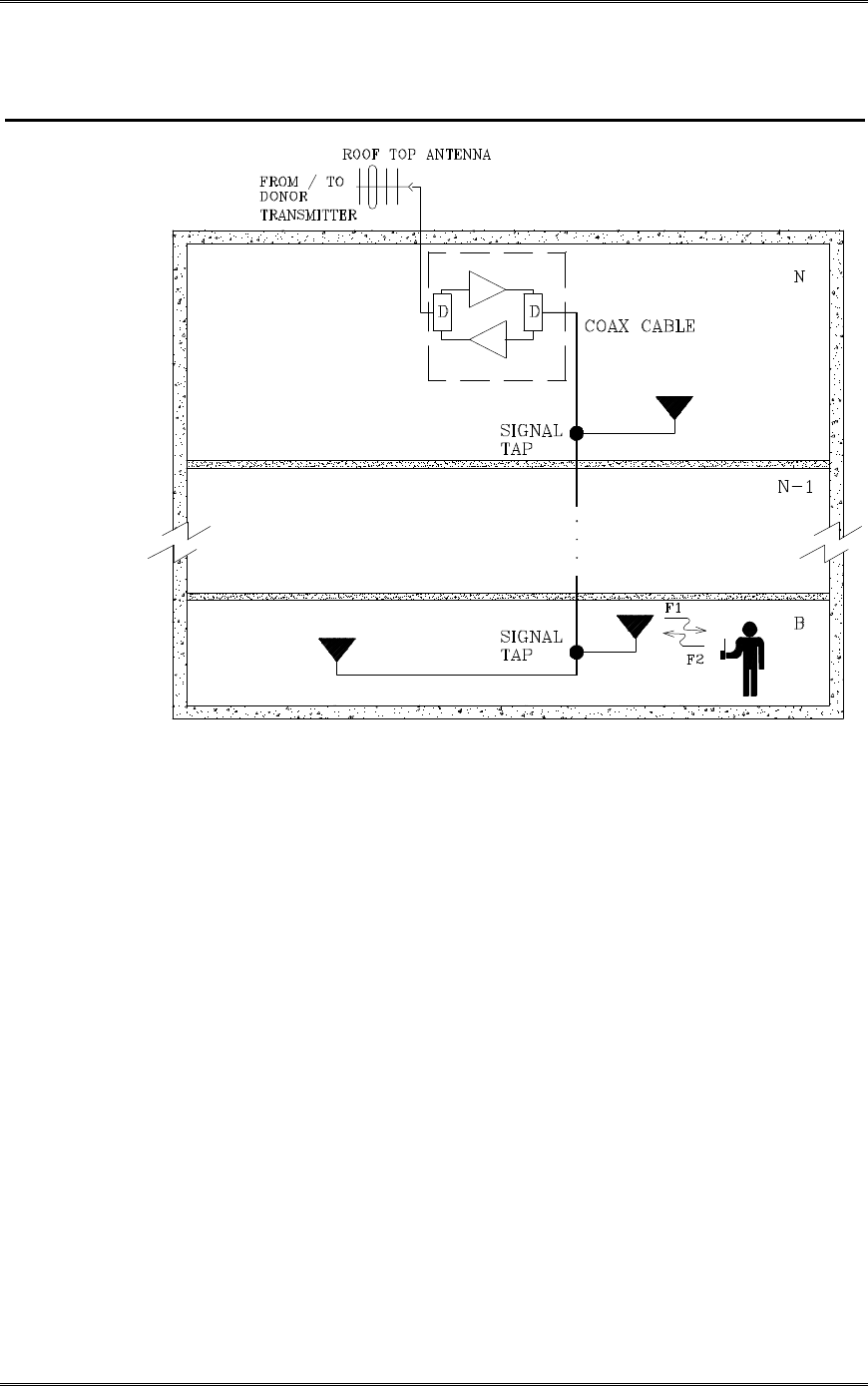
A typical in-building coverage extension system is shown in Figure 1-2. The head-end
subsystem, namely Kaval bi-directional amplifier, is responsible for the amplification of both
incoming “off-the-air” downlink signal and outgoing uplink signals. The in-building
distribution antenna system comprises of Coaxial cable, Signal taps, splitters and antennas to
extend coverage on every floor, basement and underground parking garage.
BDA1250 Equipment Manual
DCM000000013 Kaval Telecom Inc. Page 6 of 17
Figure 1-2. Bi-Directional Amplifier in RF distribution System
This distributed antenna system is based on Kaval’s patented “Tapped Radiator” RF
signal distribution approach. The technology makes use of coaxial cable with Signal
Taps strategically located and connected to Omni-directional ground plane antennas. This
technology offers flexibility in system design, installation and optimization. Once the RF
cable backbone has been installed, additional signal taps and antennas can quickly and
easily be added to a live system, without the need to take the system out of service.
Hence, new coverage areas can be added, or the system can easily be modified if the
layout should change (e.g. modernization retrofits or process modifications).
BDA1250

BDA1250 Equipment Manual
DCM000000013 Kaval Telecom Inc. Page 7 of 17
3 BDA1250 Bi-directional Amplifier Description
3.1 BDA1250 Functional Description
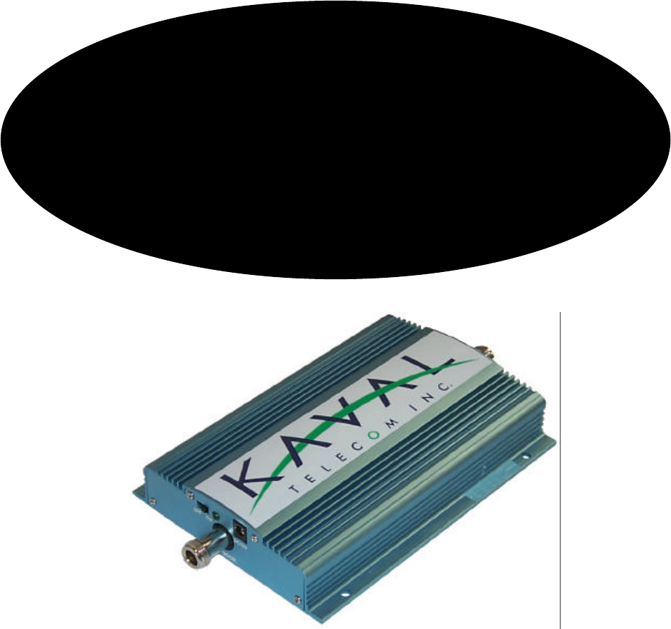
The BDA1250 series Amplifier is a compact wall mounted bi-directional Broadband
amplifier. It can be mounted in false ceilings or closets.
The BDA1250 consists of the following functions:
• BDA housing: Rugged die-cast aluminum housing ensures long life and
service.
• 1 Power Supply adapter: Operates on 120/230VAC to provide 12V DC to
amplifiers.
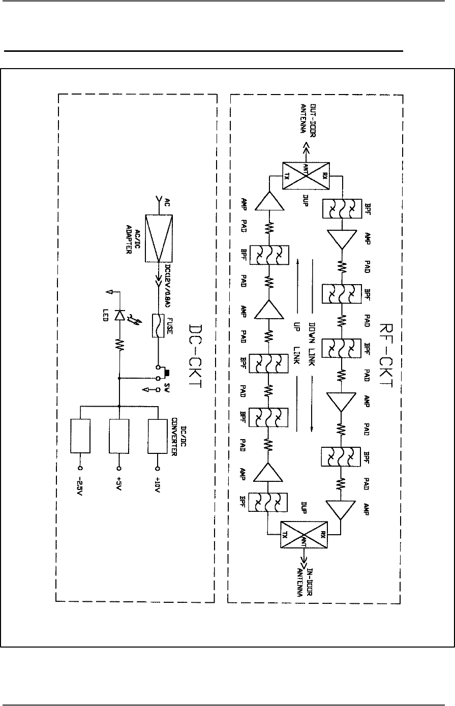
Figure 3-1 shows a block diagram of the BDA1250.
BDA1250 Equipment Manual
DCM000000013 Kaval Telecom Inc. Page 8 of 17
Figure 3-1 BDA1250 Block Diagram
BDA1250 Equipment Manual
DCM000000013 Kaval Telecom Inc Page 11 of 17
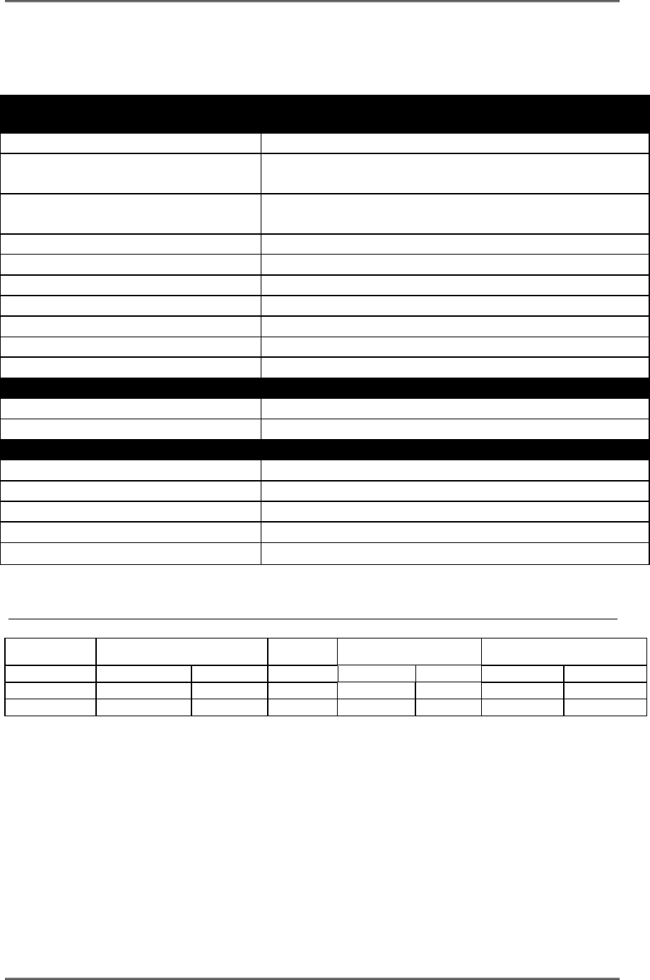
3.2 BDA1250 Specifications
3.2.1 Electrical Specifications
RF Performance Downlink Uplink
Frequency Range See model chart below
Maximum Gain (nominal) See model chart below
Digital Gain Adjustment See model chart below
Gain Adjustment 20 dB
3rd Order Intercept Point IP3 See model chart below
Noise Figure <8 dB
Propagation Delay <5 µs
Impedance 50 ohms
VSWR <2:1
Input Impedance 50 ohms
Electrical Specifications
Primary Voltage 115/230VAC, 50-60Hz
Primary Power 10 Watts
Mechanical Characteristics
Dimensions W x H x D 7.5” x 5.5”x1.5”
Weight 2 lbs. Approx.
Housing Rugged die-cast aluminum housing
Connectors N female
Operating Temperature Range -5°C to +50°C
Table 3-1 BDA 1250 Series Model Chart
Model Frequency (MHz) Maximum
Gain 1 dB Compression Point
(dBm) IP3 (dBm)
DL UL (dB) DL UL DL UL
BDA1250-C 869-894 824-849 60 28 28 35 35
BDA1250-T 851-869 806-824 60 28 28 35 35

BDA1250 Equipment Manual
DCM000000013 Kaval Telecom Inc Page 12 of 17
4 BDA Enclosure Installation
4.1 Preparation for the installation of BDA enclosures
a. Equipment and hardware required
• Each BDA is carefully packaged for air shipment. Any damage incurred during the
transportation must be claimed from the shipper.
• Make sure the following necessary equipment and hardware are available and undamaged.
• 1 BDA1250 (supplied by Kaval)
• Jumper cable (not supplied by Kaval)
• AC adapter (supplied by Kaval)
• Mounting hardware such as: Four washers and four bolts (not supplied by Kaval)
b. Preparing the installation site
• Make sure the mounting area is large enough to accommodate for the installation of the
BDA1250 (5.6”Wx1.6”Hx8.3”D) and free airflow is available around the unit.
• RF cables must be in place and labeled clearly as “Donor Cell Site” and “In-building”.
4.2 Mounting the BDA Enclosure
The physical installation is accomplished by mounting the BDA1250 in false ceilings, closets
or on a vertical wall. Using four mounting holes on the enclosure (5.82” x 5.125”, see figure
3-2) as a template insert four bolts to the wall. Make sure the bolts are capable of supporting
at least 5 lbs
4.3 Connecting the Coaxial cables
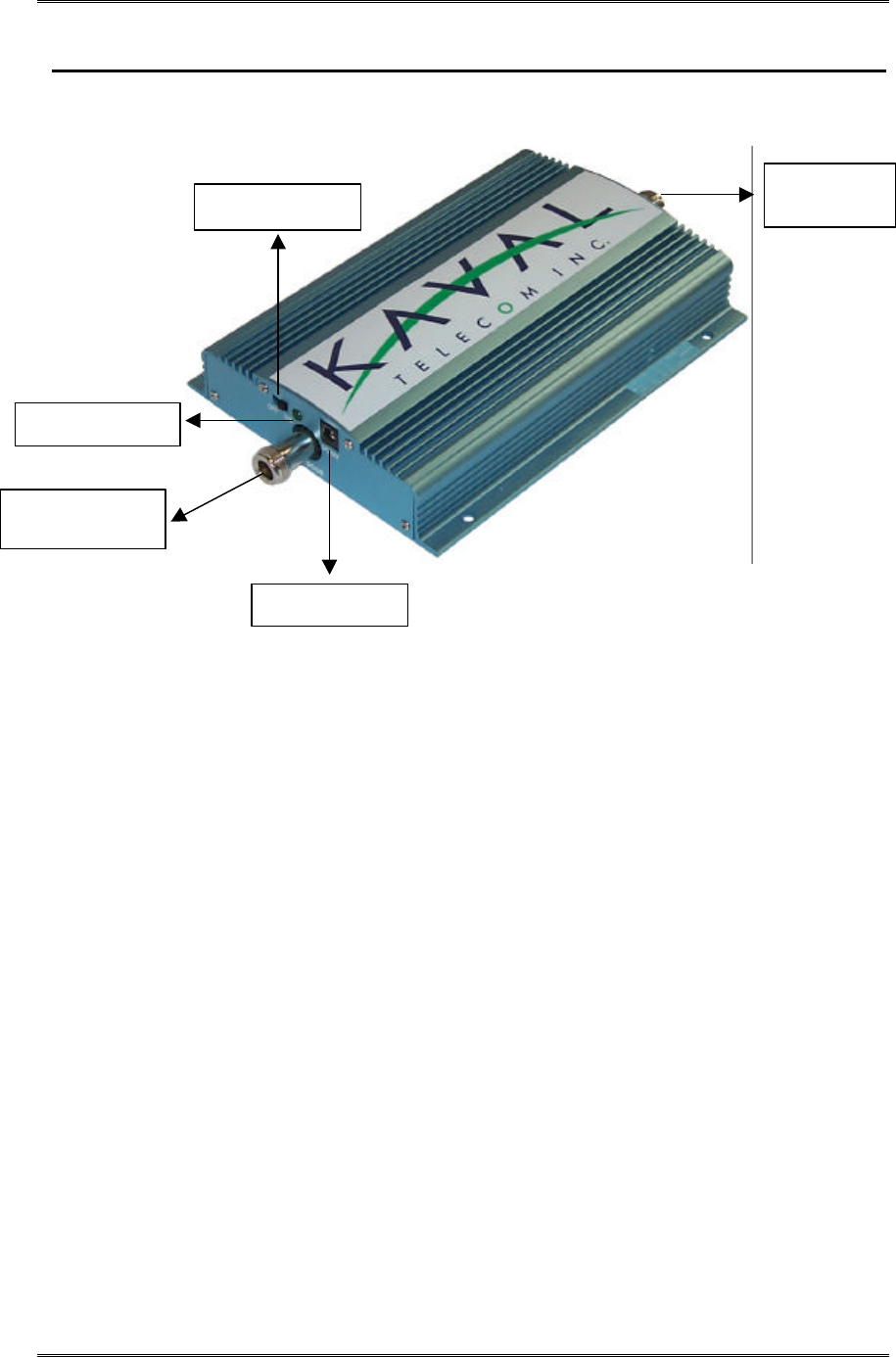
Connectors of the BDA are located on the front and back of the BDA1250 (see figure 3-2).
RF cables can be connected to these connectors using jumper cables as follows.
1. Connect one end of the first jumper cable to the BDA1250 connector marked
“Outdoor”
2. Connect the other end of the first jumper cable to the connector marked “Donor Cell
3. Connect one end of the second jumper cable to the BDA connector marked “Indoor”
4. Connect the other end of the second jumper cable to connector marked “In-building”
cable
BDA1250 Equipment Manual
DCM000000013 Kaval Telecom Inc Page 13 of 17
Figure 3-2. RF and DC Connections
4.4 Connecting the Power Cables
BDA1250 comes with AC adapter. Therefore an AC outlet providing 120 AC should be
available with 4ft of the BDA1250. If AC outlet is to be installed, it is highly recommended
that AC Power Wiring be performed by a qualified Electrician so as to ensure compliance
with all National and Local Electrical Wiring Regulations. Connecting power cables can be
done as follow:
1. Locate the on/off switch on the front of the BDA1250. Turn the switch to the OFF
position.
2. Locate a nearby AC outlet and connect AC adapter to the AC outlet.
3. Connect the DC input jack of the AC adapter to the BDA12500.
4. Make sure the adapter cable is neatly tugged away.
5. Turn the BDA1250 power switch to the ON position. LED should be luminous to
indicate the present of power.
To Outdoor
Antenna
Power Switch
LED
DC Port
To Indoor
Antenna

BDA1250 Equipment Manual
DCM000000013 Kaval Telecom Inc Page 14 of 17
5 Antenna Installation
lAll Antenna Installation is to be performed by Qualified Technical Personnel
only.
lAntenna Installation Instructions and locations below are for the purpose of
satisfying FCC RF Exposure Compliance requirements.
lThe Roof Top Antenna for linking to the Donor Site is a directional (high gain)
Antenna fixed-mounted physically on the side or top of a building, or on a tower. The
Antenna Gain must be no more than 10 dBi. The Roof Top Antenna location should be
such that only Qualified Technical Personnel can access it, and that under normal
operating conditions no other person can touch the Antenna, or approach within 10
meters of the Antenna.
lThe In-Building Antenna connection is via a coaxial cable distribution system with
Signal Taps at various points connected to the fixed-mounted Indoor Antennae. This
is shown in the figure in the Introduction. The Indoor Antennae are simple 1/4
Wavelength (0 dBi Gain) types. They are used with Kaval 12, 16, or 20 dB Cable
Taps. As such the maximum EIRP will be at the first Tapped Antenna, which will be
12 dB below the maximum signal level of the BDA1250; +28 dBm, or 0.63 Watts
EIRP. These Antennae are to be installed such that no person can touch the Antenna,
or approach within 0.2 Meters.
ANTENNA INSTALLATION
WARNING
ALL ANTENNA INSTALLATION IS TO BE PERFORMED BY QUALIFIED TECHNICAL
PERSONNEL ONLY.
ANTENNA INSTALLATION INSTRUCTIONS AND LOCATIONS ARE FOR THE PURPOSE
OF SATISFYING FCC RF EXPOSURE COMPLIANCE REQUIREMENTS, AND ARE NOT
OPTIONAL.
ALL ROOF TOP ANTENNA INSTALLATION MUST BE SUCH THAT NO PERSON CAN
TOUCH THE ANTENNA, OR APPROACH CLOSER THAN 10 METERS.
ALL IN-BUILDING ANTENNAE INSTALLATIONS MUST BE SUCH THAT NO PERSON
CAN TOUCH THE ANTENNAE, OR APPROACH CLOSER THAN 0.2 METERS.

BDA1250 Equipment Manual
DCM000000013 Kaval Telecom Inc Page 15 of 17
6 Troubleshooting and Maintenance
6.1 Maintenance
6.1.1 Maintenance & Safety
The BDA has been engineered for easy maintenance and for safe operation. This has
been achieved as follows:
lBDA1250 provides fault monitoring and accurate status report through LED.
lThe AC adaptor is over-rated for actual requirements.
lComponents are easily removable via quick AC adaptor DC and RF connectors.
6.1.2 Maintenance Philosophy
Field maintenance should require a screwdriver, a multi-meter, spares AC adaptor and
Portable Radio to monitor off the air signals. There is no requirement to have any test
equipment to accomplish most service repairs.
l BDA component parts have been designed for reliable long life operation.
lCorrective action can often be taken without detailed technical knowledge or the
need for any test equipment.
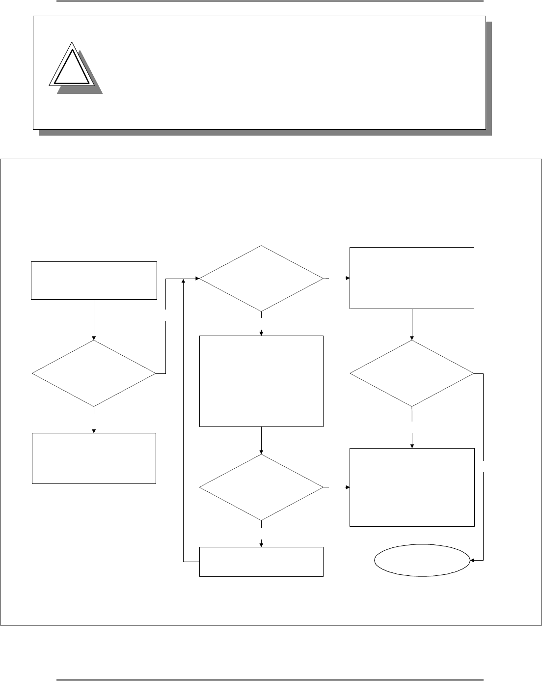
6.2 Troubleshooting Procedure
1. Before attempting to troubleshoot the BDA, you should study the troubleshooting
flowchart carefully.
2. Always observe personal and equipment safety practices during troubleshooting.
3. Follow each step of the troubleshooting flowchart to check for the fault and to
replace the recommended component.
4. Recommended Test Equipment:
• Multimeter
• Spare AC adaptor for substitution.
• Phillips screwdrivers
BDA1250 Equipment Manual
DCM000000013 Kaval Telecom Inc Page 16 of 17
Note: If you are not familiar with electronic
system troubleshooting, Please contact Kaval at
1-888-86-KAVAL for assistance or ask for a
RMA (Return Material Authorization) before
sending BDA unit to an authorized service agent
!
!
Donor Site &
Portable Radio
Equipment perform
satisfactory?
No
Is Power LED
lit?
1. Make sure the AC adaptor is
connected properly to the
BDA1250 and the AC outlet.
2. Check the AC outlet with a
multimeter.
3. Check the DC output of the
AC adaptor with a multimeter.
Does the AC adaptor
provide 12 Vdc output?
Is there RF coverage?
No
Yes
Replace BDA1250
Note:
the new BDA1250 gain should
be set with the same settings as
that of the existing BDA1250
prior to replacement.
Start
Troubleshooting Procedure
Fix or Optimize Donor Site
and / or Portable Radio
Equipment
Replace the AC adaptor
No
Yes
1. Turn Power switch of BDA
off and on Again.
No
TROUBLESHOOTING FLOWCHART
Yes
End
Troubleshooting
Yes

BDA1250 Equipment Manual
DCM000000013 Kaval Telecom Inc Page 17 of 17
7 STANDARD WARRANTY
Products manufactured by Kaval Telecom Inc. are warranted to be free under normal use
and service from defect in workmanship or materials for a period of one year from the
date of shipment to the original purchaser. This warranty supersedes and voids any and
all other warranties expressed or implied.
In no event shall Kaval Telecom Inc. be liable for incidental or consequential damages
arising from the use, misuse, failure to operate or improper operation of any Kaval
product or product accessory.
Specifically excluded from this warranty is any claim of merchantability or fitness for a
particular purpose or application.
This warranty is void if the product has been subject to misuse, neglect, accidental
damage, damage of a cosmetic nature, misapplication, extreme environmental conditions,
unauthorized repair or alteration.
Customer must contact Kaval Telecom before shipping a product for warranty services to
obtain a Returned Material Authorization. Shipping charges for returned products must
be PREPAID. A return shipping fee will be charged if a returned item is found by Kaval
not to be defective or defective for a reason that voids the warranty.

BDA1250 Equipment Manual
DCM000000013 Kaval Telecom Inc Page 18 of 17
8 Product Service Procedure
Return and Repair Procedures
BDA1250 Line amplifier can be returned for repair by the following procedures:
• Contact Kaval Telecom Inc. at 1888-86-KAVAL for a Return Materials Authorization
(RMA) number. Please provide serial number and model number.
• Ship the defective part prepaid in the original shipping box to:
Kaval Telecom Inc.
ATTN: Returned Part; RMA number:XXXX
60 Gough Road
Markham, On
L3R 8X7
Canada

BDA1250 Equipment Manual
DCM000000013 Kaval Telecom Inc Page 19 of 17
9 Ordering Parts and Accessories
Parts ordering information
Parts and accessories for the BDA1250 Line amplifier can be purchased by contacting Kaval
Telecom Inc. at 1888-86-KAVAL for prices and delivery. When ordering a replacement part,
please provide model number, serial number and software version number (See BDA
Controller Settings-“As-Built” list).