Powerwave Technologies OFR400 LINKnet OFR400 RF Repeater Module User Manual users manual part 1
Powerwave Technologies Inc. LINKnet OFR400 RF Repeater Module users manual part 1
Contents
- 1. users manual part 1
- 2. users manual part 2
- 3. users manual part 3
users manual part 1
LINK
LINKLINK
LINK
net
netnet
net
™
™™
™ USER MANUAL
USER MANUAL USER MANUAL
USER MANUAL
INSTALLATION, OPERATION AND
INSTALLATION, OPERATION AND INSTALLATION, OPERATION AND
INSTALLATION, OPERATION AND
MAINTENANCE
MAINTENANCEMAINTENANCE
MAINTENANCE
KAVAL TELECOM INC.
60 Gough Road
Markham, Ontario
L3R 8X7
Telephone: (888) 86-KAVAL
Web: www.kaval.com
E-mail: info@kaval.com
Document #DCM00000008, Rev.2

LINKnet™ ! USER MANUAL DCM000000008
Printed: 2000-03-22 09:08:05
Revision Date: 3/22/00: ii
P
PP
P
P
PP
PR
RR
R
R
RR
RO
OO
O
O
OO
OP
PP
P
P
PP
PR
RR
R
R
RR
RI
II
I
I
II
IE
EE
E
E
EE
ET
TT
T
T
TT
TA
AA
A
A
AA
AR
RR
R
R
RR
RY
YY
Y
Y
YY
Y
S
SS
S
S
SS
ST
TT
T
T
TT
TA
AA
A
A
AA
AT
TT
T
T
TT
TE
EE
E
E
EE
EM
MM
M
M
MM
ME
EE
E
E
EE
EN
NN
N
N
NN
NT
TT
T
T
TT
T
© 2000 KAVAL TELECOM INC. All rights reserved.
No part of this publication, or any software included with it may be reproduced, stored in a retrieval system,
or transmitted in any form or by any means, including photocopying, electronic, mechanical, recording or
otherwise, without the prior written permission of the copyright holder.
This document contains proprietary information of KAVAL TELECOM INC. The contents are confidential and
any disclosure to persons other than the officers, employees, agents or subcontractors of the owner or
licensee of this document, without the prior written consent of KAVAL TELECOM INC., is strictly prohibited.
KAVAL TELECOM INC. provides this document as is, without any warranty of any kind either expressed or
implied including, but not limited to, the implied warranties of merchantability and fitness of a particular
purpose. KAVAL TELECOM INC. may make changes or improvements in the equipment, software, or
specifications described in this document at any time and without notice. These changes will be incorporated
in new releases of this document.
This document may contain technical inaccuracies or typographical errors. KAVAL TELECOM INC. waives
responsibility for any labour, materials, or costs incurred by any person or party as a result of using this
document. KAVAL TELECOM INC., and any of its affiliates shall not be liable for any damages (including,
but not limited to, consequential, indirect or incidental, special damages or loss of profits or date) even if they
were foreseeable and KAVAL TELECOM INC. has been informed of their potential occurrence, arising out of
or in connection with this document or its use.
LINKnet™ ! USER MANUAL DCM000000008
Printed: 2000-03-22 09:08:05
Revision Date: 3/22/00: iii
R
RR
R
R
RR
RE
EE
E
E
EE
EV
VV
V
V
VV
VI
II
I
I
II
IS
SS
S
S
SS
SI
II
I
I
II
IO
OO
O
O
OO
ON
NN
N
N
NN
N
R
RR
R
R
RR
RE
EE
E
E
EE
EC
CC
C
C
CC
CO
OO
O
O
OO
OR
RR
R
R
RR
RD
DD
D
D
DD
D
Rev. № Page № Description of Revision Date
0 Pre-release All Draft Issues. Feb.2000
1 All Original Release Mar.6,2000
2 All Updated drawings and Logos Mar.21,2000
T
TT
T
T
TT
TR
RR
R
R
RR
RA
AA
A
A
AA
AD
DD
D
D
DD
DE
EE
E
E
EE
E
M
MM
M
M
MM
MA
AA
A
A
AA
AR
RR
R
R
RR
RK
KK
K
K
KK
K
N
NN
N
N
NN
NO
OO
O
O
OO
OT
TT
T
T
TT
TI
II
I
I
II
IC
CC
C
C
CC
CE
EE
E
E
EE
E
This manual makes reference to trademarks that are the property of other companies. References are used
only to refer to the products or services of the trademark owners.
LINKnet™ is a trademark of KAVAL TELECOM INC.

LINKnet™ ! USER MANUAL DCM000000008
Printed: 2000-03-22 09:08:05
Revision Date: 3/22/00: iv
TABLE OF CONTENTS
TABLE OF CONTENTSTABLE OF CONTENTS
TABLE OF CONTENTS
1. PREFACE ................................................. 1
CONVENTIONS USED IN THIS MANUAL ..................... 1
GLOSSARY OF TERMS............................................. 2
2. INTRODUCTION....................................... 3
DOCUMENT SCOPE................................................. 3
WHAT IS THE ......................................................... 3
LINKNET™ PLATFORM?......................................... 3
3. CARD-CAGE ............................................ 4
OFR1000 CARD-CAGE SPECIFICATIONS ................. 4
CARD-CAGE DESCRIPTION ...................................... 4
CARD-CAGE DRAWING (FRONT VIEW)...................... 4
CARD-CAGE DRAWING (REAR VIEW) ....................... 5
OFR000 SPACER MODULE ......................................... 6
CARD-CAGE MAINTENANCE .................................... 6
4. CONTROL MODULE ................................ 7
5. POWER SUPPLY MODULE..................... 8
POWER SUPPLY SPECIFICATIONS ............................ 8
DESCRIPTION ......................................................... 8
Normal Operation ............................................. 8
FUSE ..................................................................... 9
Location: ........................................................... 9
Replacement: ................................................... 9
BATTERIES............................................................. 9
Operation without batteries............................... 9
Operation with batteries.................................... 9
Battery Requirements:.................................... 10
Battery Sizing ................................................. 10
Battery Cable.................................................. 11
Battery Charge Time ...................................... 12
Battery Maintenance....................................... 12
6. PHYSICAL INSTALLATION................... 13
CARD-CAGE (ENCLOSURE).................................... 13
POWER SUPPLY ................................................... 13
AC Power Connection .................................... 14
BATTERY.............................................................. 14
Battery connection.......................................... 14
RF MODULES....................................................... 15
EXPANDING THE SYSTEM ...................................... 15
Additional Modules ......................................... 15
Additional LINKnet™ card-cages ................... 15
Card-cage ID number ..................................... 16
Group Termination.......................................... 16
EXTERNAL FAULT INDICATION ................................ 16
Battery connection.......................................... 17
SYSTEM CONFIGURATION PROGRAMMING.............. 17
Installing the software..................................... 17
Cable connections .......................................... 17
Running the program ...................................... 18
7. MAINTENANCE...................................... 19
8. TROUBLE SHOOTING........................... 20
9. WARRANTY INFORMATION ................. 21
PRODUCT WARRANTY........................................... 21
RMA PROCEDURE ............................................... 21
Appendix A: Quick Reference......................... 22
PART NUMBERS ................................................... 22
See attached sections for individual models of
RF Modules.
LINKnet™ ! USER MANUAL
Printed: 00.03.22,09:08
Revision Date:3/22/00 1
Several text fonts have been used to indicate special words or terms. The meaning
or definition of text appearing in bold type can be found in the glossary. Texts
appearing in italic type are nouns - proper names of persons, companies, known
registered trademarks, other manuals, or parts of the system. Text in BOLD
CAPITALS refers to buttons, indicators or connectors on the operator console or the
specifically indicated panel.
The exclamation mark icon appears next to text of critical importance. Failure to
read these items may result in damage to equipment or personnel.
The STOP Icon appears next to critical steps in procedures. Failure to precisely
follow these steps will cause damage to the equipment or personnel.
This icon appears next to examples.
This icon appears next to useful information.
1. PREFACE
Conventions Used In
This Manual

LINKnet™ ! USER MANUAL DCM000000008
Printed: 00.03.22,09:08
Revision Date:3/22/00 2
Term Meaning
Back plane Multi-layer electronic mounting board the forms the back of the Card-cage
enclosure, and allows for a common interface for the plug in modules
Card-cage Rack mounted sub-rack assembly, allows the modules to have a common
interface
Control Port
connector
Each RF Module has a communication/set-up port that feeds through the
Back plane, and terminates with a control connector. This port can be used
through a PC to communicate with the RF Module for set-up
Controller Module Self contained Controller Module that stores, downloads, alters, and monitors
all of the installed modules in the system. This module is optional.
Daisy chained Multiple Card-cages may be cascaded, or joined to form a large system
Expansion cable Custom wiring harness to interconnect multiple Card-cages
Hot swap RF Modules may be inserted or removed while the system is operational
Power Supply
Module
A Self contained Power Supply Module, specifically designed to be inserted
into the LINKnet™ platform Card-cage
PS Public Service Channels
Trunking A block of reserved channels, usually for public service use
RF Module A self contained repeater that has been specifically designed to be inserted
into the LINKnet™ platform Card-cage
SMR Acronym for “Special Mobile Radio”.
Spacer Module
A 3 dimensional spacer specifically designed to be inserted into the
LINKnet™ platform Card-cage. The spacer ensures proper circulation in
partial systems.
Threshold The minimum signal level that can be detected
Glossary of Terms

LINKnet™ ! USER MANUAL DCM000000008
Printed: 00.03.22,09:08
Revision Date:3/22/00 3
Congratulations on your purchase of the LINKnet™ platform.
Successful operation of the LINKnet™ in any installation depends upon sound
system design. Service personnel should be aware that most problems experienced
with LINKnet™ systems are due to failures or inadequacies in equipment outside the
LINKnet™ platform.
This manual pertains to the LINKnet™ Platform. It describes how the user should
install, set-up and use the LINKnet™ Card-cage, Power Supply Module, and Plug in
RF and Controller modules, for proper operation and safety.
The scope of this manual is generally limited to the LINKnet™ circuitry itself; no
attempt is made to thoroughly discuss all aspects of system or applications design.
KAVAL TELECOM INC. would be pleased to discuss the engineering aspects of
LINKnet™ installations and can undertake overall LINKnet™ system design and
installation.
The LINKnet™ encompasses the functionality of most of KAVAL TELECOM INC.’s
current electronic product line. All OFR and BDA products are harmonized into a
single modular and adaptable system. The intention is to incorporate the
functionality of most or all of KAVAL TELECOM INC.’s product line into a single
modular family. Newer technology allows implementation of additional features such
as Digital Control, Self-alignment, and Extensive Diagnostics, which make the
modules in this new generation of products more capable than their predecessors.
The product is made up of at least one Card-cage, RF Modules, and a Power
Supply. The Modules in the Card-cage interconnect via a back plane that supplies
power and digital control signals.
A single Card-cage can be mounted into a 6 unit standard EIA 19 inch rack, with
multiple Card-cages interconnected using a Card-cage Interconnect Harness.
An optional Control Module may be used to program and monitor the independent
RF Modules. By daisy chaining Card-cages together, a single control module can
be used to run up to 110 RF Modules in a single, integrated, system.
2. INTRODUCTION
Document Scope
What Is The
LINKnet™ Platform?
LINKnet™ ! USER MANUAL DCM000000008
Printed: 00.03.22,09:08
Revision Date:3/22/00 4
SPECIFICATION VALUE
Basic Construction 19” Rack based Card-Cages
Card-Cage Features
Each Card-Cage may contain up to 7 RF Modules without a Controller
Module, or up to 5 RF Modules with a Controller Module. Modules
inserted into the Card-Cage are auto-identified as to type, and which
card slot they are in. Card-cages are identified by a rear-panel switch
setting (0-15).
Card-Cage Connections
DB-15 Connector provides for extra Card-Cages to be cascaded via
an Expansion cable. The connector also provides a common Fault
Relay.
Size Standard 19” Rack Mount, 6U (10.5”) High, 14.00” Deep
Weight TBD
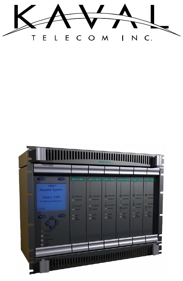
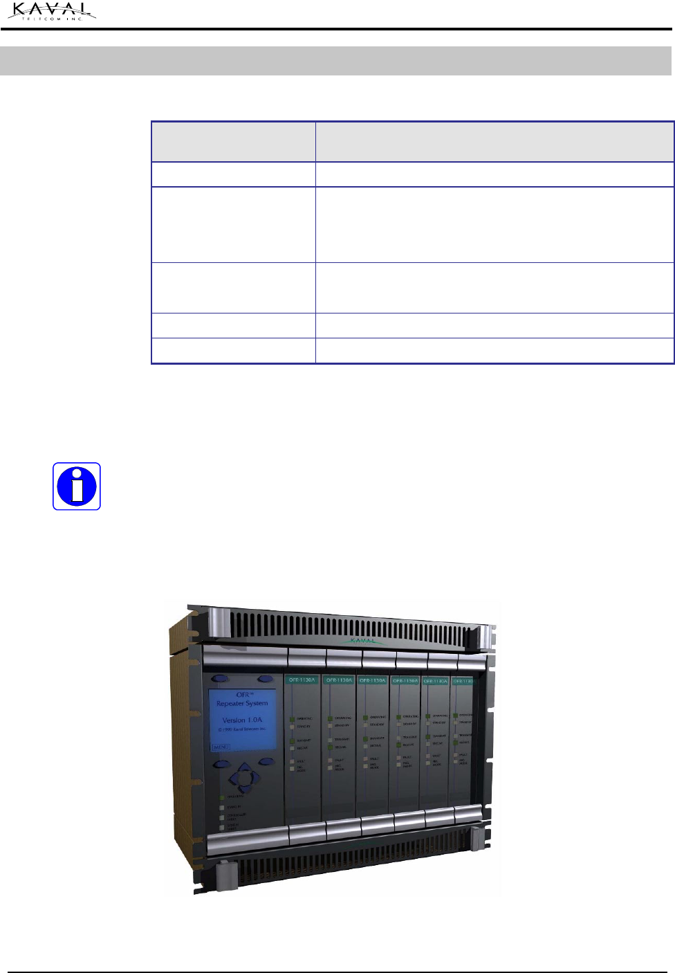
The LINKnet™ Model OFR1000 card-cage is a standard 19-inch rack mounted box,
6U high (10.5”), and 14” deep. The unit comes with a Power Supply Module
(PS400A), and will hold up to 7 modules. All modules slide in on pre-installed
tracks, and their faceplates together with the front flange form the front cover when
the system is assembled.
OFR000 Spacer (blank) modules must be used to fill un-used module slots. The
surrounding flange completes the unit while protecting the mounting screws,
allowing for an air grill, and covering any sharp edges.
Front view of a card-cage showing from left to right: Four spacer modules, a RF
module, one spacer module, another RF module and a power supply module.
3. CARD-CAGE
OFR1000 Card-cage
Specifications
Card-cage Description
Card-cage Drawing
(Front View)
LINKnet™ ! USER MANUAL DCM000000008
Printed: 00.03.22,09:08
Revision Date:3/22/00 5
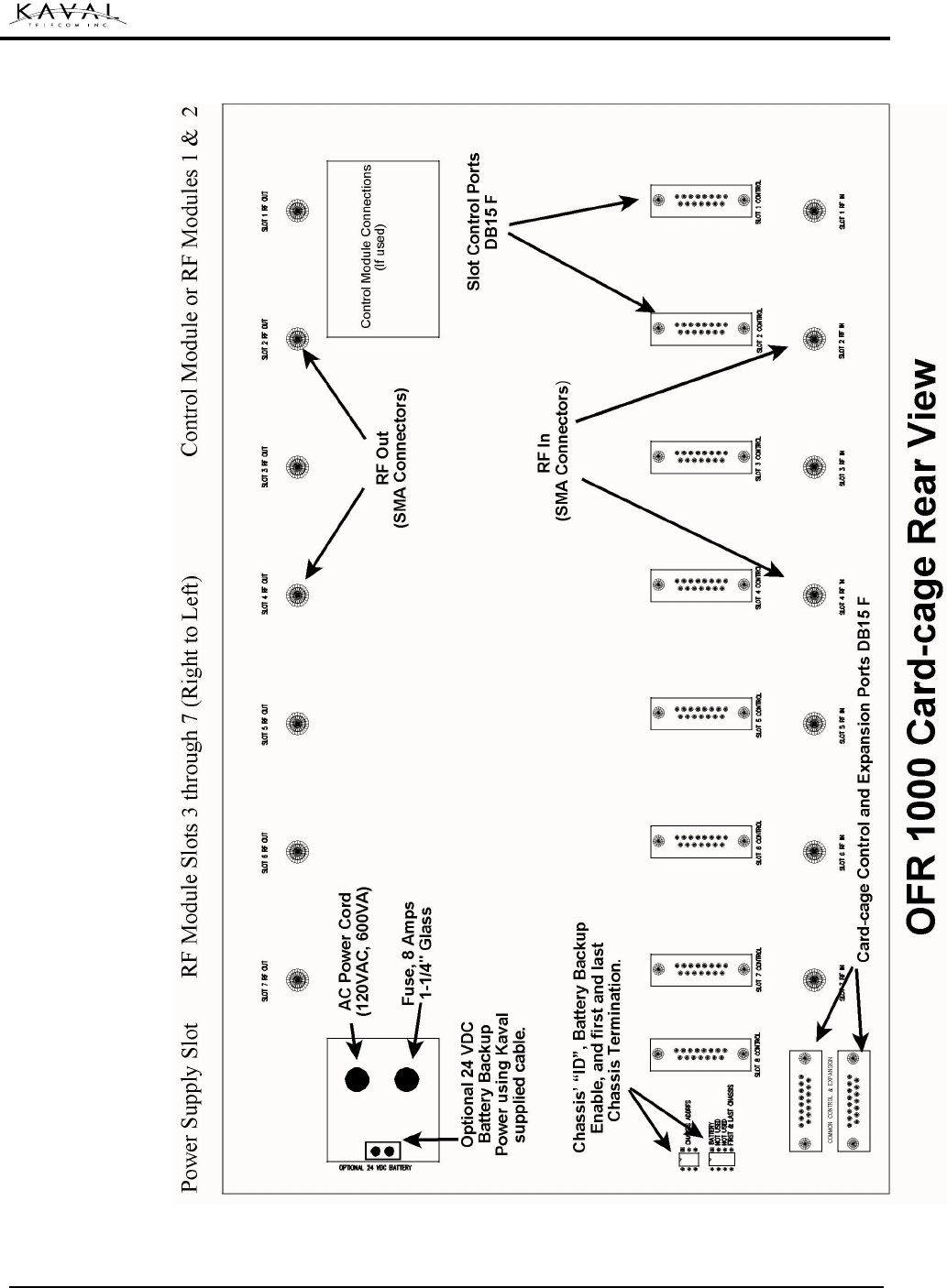
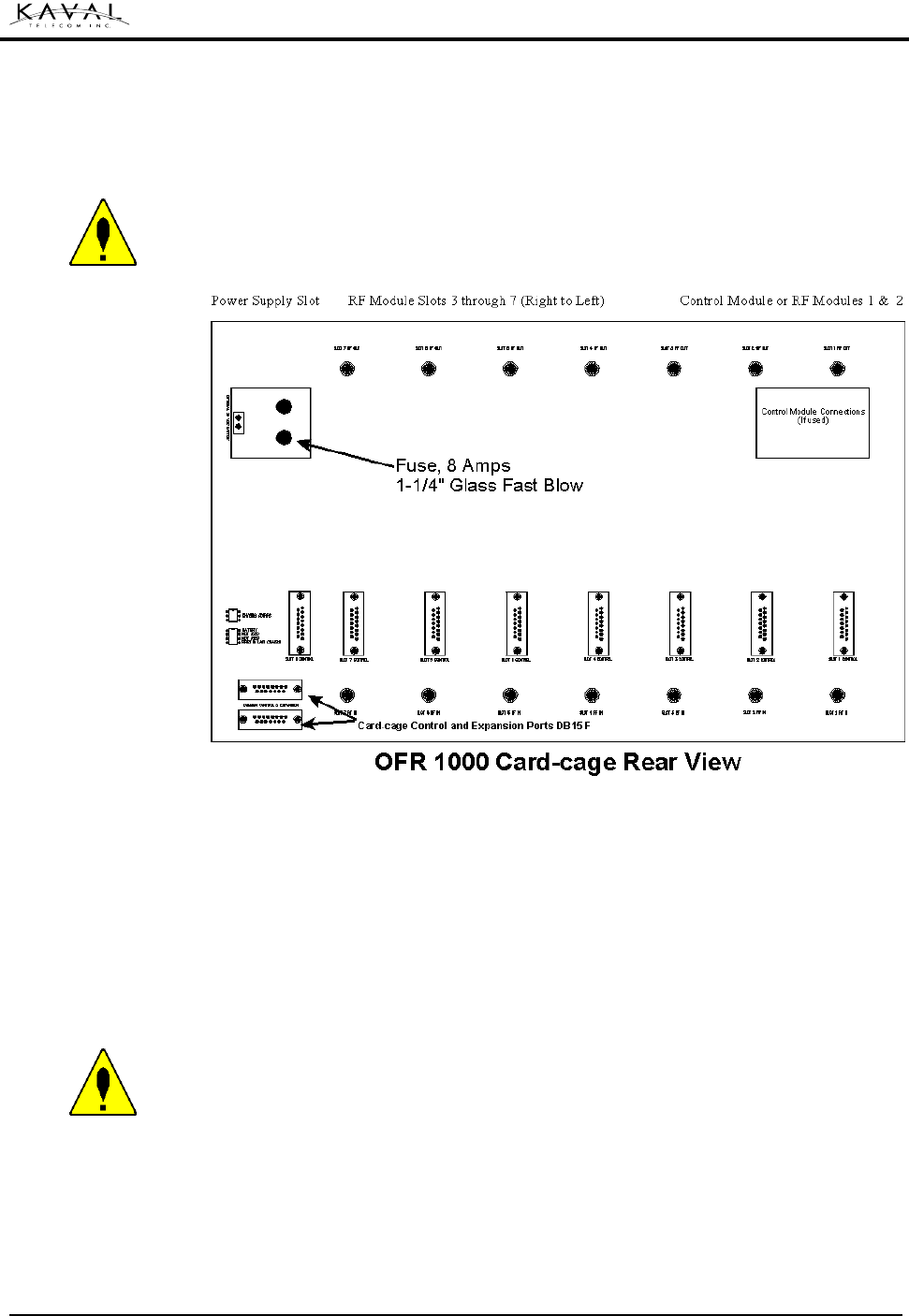
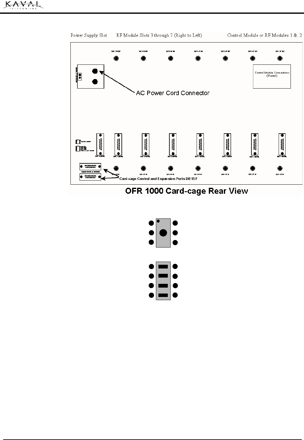
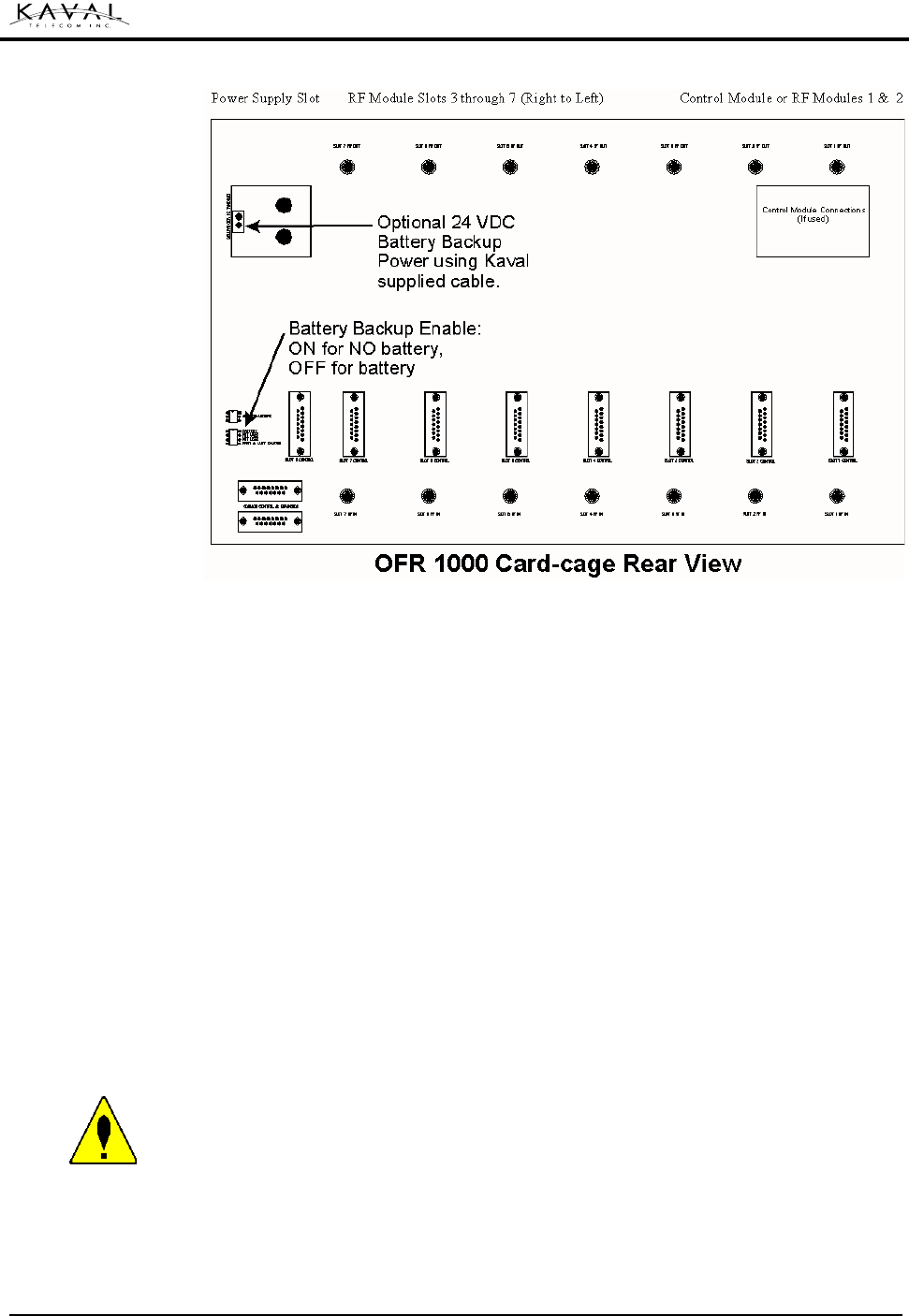
Card-Cage Drawing
(Rear View)
LINKnet™ ! USER MANUAL DCM000000008
Printed: 00.03.22,09:08
Revision Date:3/22/00 6
In installations where one or more module slots are not used, OFR000 Spacer
Modules will be installed in the un-used slots. These modules close the front panel
and ensure the proper flow of air around the heat sinks. Should additional modules
be required at some future date, the spacer module(s) may be removed and the new
module placed into the open space.
The power inside the card-cage is limited to low voltage. The spacer module is not
intended as an electrical safety feature.
It is recommended that spacer modules remain installed while the system is
operational, and that the preventative maintenance outlined in the maintenance
section of this manual be followed.
The LINKnet™ card-cage requires little or no maintenance once it is assembled.
During routine inspection of the system, it is recommended that excessive dust be
removed, especially from all fans, filters, and cooling fins. It is also recommended
that all external cables be inspected for damage.
OFR000 Spacer Module
Card-Cage
Maintenance

LINKnet™ ! USER MANUAL DCM000000008
Printed: 00.03.22,09:08
Revision Date:3/22/00 7
This module is optional.
4. CONTROL MODULE
LINKnet™ ! USER MANUAL DCM000000008
Printed: 00.03.22,09:08
Revision Date:3/22/00 8
SPECIFICATION VALUE
Card-Cage Power Supply
Module
Right-most Module, supplied with the Card-Cage. Rated at 400
Watts, providing +12V & +28V to the Modules. Requires 120/240
VAC 50/60 Hz.
Card-Cage Battery Backup
Optionally may provide a Battery-Backup Operation using two
external 12V sealed lead-acid Batteries, and an optional Kaval
CAB000000055 Battery Cable.
Size Standard 19” Rack Mount, 6U (10.5”) High, 14.00” Deep
Weight TBD
Each LINKnet™ Card-cage comes with it’s own Power Supply Module (model
PS400A). The Power Supply Module is mounted in the extreme right slot of the
Card-cage and supplies power to the installed modules via the Back plane
connector.
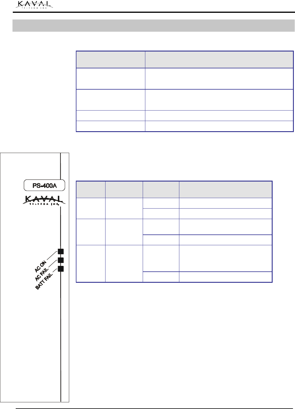
Normal Operation
LED Colour Status Description
ON Illuminated when AC Power Present
AC ON Green
OFF Not illuminated when AC power absent
ON Illuminated when AC absent, and
platform is being powered externally
AC FAIL Red
OFF
ON
Illuminated when AC power present,
but no external power source present.
Note: this LED can be disabled if a
secondary power source is not required
Battery
FAIL Red
OFF
Under normal operation the "AC On" LED (Green) will illuminate and will remain on
when power is connected. If there is a power disruption and there is a secondary
power source the AC Fail LED will illuminate (RED).
One power supply module is always included with each card-cage. The power
supply module also includes circuitry to support a battery backup system.
Connecting a battery to the appropriate connection will automatically enable
switching to the backup system whenever there is a disruption in AC power.
The module is designed for either 120 VAC 50/60 Hz (6 Amps) or 240 VAC 50/60
Hz (3 Amps) input, and is rated at 400-Watts, providing +12V and +28V output to the
installed modules via the LINKnet™ back plane. Replacement AC Power Cables are
Kaval Model # CAB000000058.
5. POWER SUPPLY MODULE
Power Supply
Specifications
Description
LINKnet™ ! USER MANUAL DCM000000008
Printed: 00.03.22,09:08
Revision Date:3/22/00 9
Location:
The Fuse is located on the upper left of the back plane board. .
Replacement:
Replace the fuse with 1¼ x ¼-inch glass fuse 8 Amps fast blow.
Operation without batteries
If the LINKnet™ is being used without a Battery the switch on the lower left of the
back plane must be set for “Battery Absent” (See Back plane Drawing below).
Failure to do this will cause the Battery Fail LED to remain on at all times.
Note: Without a battery connected to the LINKnet™ Card-cage, the system will shut
down or reset with any disruption to the AC power. When power is re-established
the system will restart automatically.
Operation with batteries
External batteries may be connected to the LINKnet™ Card-cage, by using the
appropriate cable assembly. When batteries are used, the selector switch on the
back plane must be set for Battery Present (See Back plane Drawing above). When
this is done, the Power Supply Module will automatically switch to battery when AC
power is disrupted. The battery charger will automatically recharge the attached
battery.
Fuse
Batteries

LINKnet™ ! USER MANUAL DCM000000008
Printed: 00.03.22,09:08
Revision Date:3/22/00 10
Battery Requirements:
• One 24V Battery is required for each Card-cage (usually consisting of two 12V
batteries).
• The battery must be a Sealed Lead Acid type (often called Gel Cell).
• Batteries must be installed in a ventilated area in accordance with the
manufacturer’s instructions.
• If a longer cable assembly is required, contact the KAVAL TELECOM INC. factory
by E-mail: info@kaval.com.
• For battery capacity in Amp Hours (A-H) see section “Battery Sizing” below.
• For charging time for batteries, in hours, see chart below.
• If batteries are stored (not connected to the system) they should not be left in a
low state (discharged) for more than a few days, or they will permanently lose
capacity, and no longer be able to run the system.
• If it is desired to be able to recharge the batteries at a rate faster than is inherent
in the power supplies internal system, then it is possible to use an external
charger. Consult the KAVAL TELECOM INC. factory for details at E-mail:
info@kaval.com
Battery Sizing
The size or capacity of the external lead acid batteries is dependent on two
variables
:
The number of modules installed in the Card-cage and the desired back
up period in hours. The relationship is defined by the following equation:
15
...)3215( ++++×
=pppT
C
Where:
C IS The required battery capacity in Amp Hours (A-H)
Note: the calculation is for each of the two 12V batteries required to make up the 24V
requirement
T IS The desired back up period in hours
Px IS The power consumption in watts for each plug in module in the Card-cage,
(Not counting the Power Supply Module)
Example of calculating the battery capacity:
To find the capacity in Amp Hours (C) for a system with three OFR800 modules,
where a 3-Hour reserve (T) is required.
Let:
T = 3 hours
Px = 45 watts (the power requirements of the OFR800 Module from its spec sheet)
Therefore the required battery capacity in A-H would be:

LINKnet™ ! USER MANUAL DCM000000008
Printed: 00.03.22,09:08
Revision Date:3/22/00 11
15
)3215( pppT
C+++×
=
15
)4545455(3 +++×
=C
15
)140(3×
=C
C = 28 A-H
This system example would require two 12V (in series for 24V) batteries rated at 28
A-H each
Battery Cable
The Battery Cable required is the Kaval Model # CAB000000055.
LINKnet™ ! USER MANUAL DCM000000008
Printed: 00.03.22,09:08
Revision Date:3/22/00 12
Battery Charge Time
The time required to charge the batteries using the internal battery charger, is
dependant on the capacity (C) of the battery connected to the system.
To calculate the Recharge time in hours (T), multiply 1.2 times the Amp Hour
Capacity (C):
CT ×= 2.1
Example of calculating the recharge time:
The time required charging the batteries in the example system above,
Where:
C = 28 AH From the above example
Therefore: the required time to recharge the batteries in hours would be:
CT ×= 2.1
282.1 ×=T
6.33=T Hours
It would take 33.6 hours (33 hours and 36 minutes) to recharge a system that had
three OFR800 modules, and required a 3-hour battery power reserve.
Battery Maintenance
In order to ensure the proper functioning of your LINKnet™ system, it is very
important to follow the battery manufacturer’s instructions for routine and
preventative maintenance. KAVAL TELECOM INC. recommends that all sealed
lead acid batteries be replaced at least once every 5 years.
LINKnet™ ! USER MANUAL DCM000000008
Printed: 00.03.22,09:08
Revision Date:3/22/00 13
Install the LINKnet™ card-cage into an EIA 19” rack using 4 screws. Ensure that no
cables or other equipment rests on top of the LINKnet™ and places an excessive
downward force on the rear of the unit.
The RF Antenna connections are designed for the specific RF unit. They may be
different for each RF module, so they are described in the chapter specific to each
RF module. These instructions must be followed precisely in order to ensure the
safe functioning of the radio transmitter.
Ensure that airflow around the rear panel heat sink is unobstructed. In high duty
cycle installations, it is recommended that one rack unit of clear space be left both
above and below the LINKnet™. If several units are installed in the same rack, an
external fan blowing air past the heat sinks is recommended.
The LINKnet™ is intended for indoor use only, in an environment suitable for
electronic equipment. Do not expose to excess humidity
Slide the power supply module into the right hand slot of the LINKnet™ rack. Make
sure that the Module is aligned with the guide tracks on the Card-cage, and sliding in
straight. The edge connector at the rear of the module must be seated securely and
evenly. Tighten the retaining screws to secure the module, and connect the AC
power to the appropriate connector in the upper left of the Card-cage back plane.
ALERT: Do not force the module into position. It should slide in with little or no
force. If the module resists, remove it and inspect the slides and the connectors. If
still unable to insert the module contact KAVAL TELECOM INC.
6. PHYSICAL INSTALLATION
Card-cage (Enclosure)
Power Supply
LINKnet™ ! USER MANUAL DCM000000008
Printed: 00.03.22,09:08
Revision Date:3/22/00 14
AC Power Connection
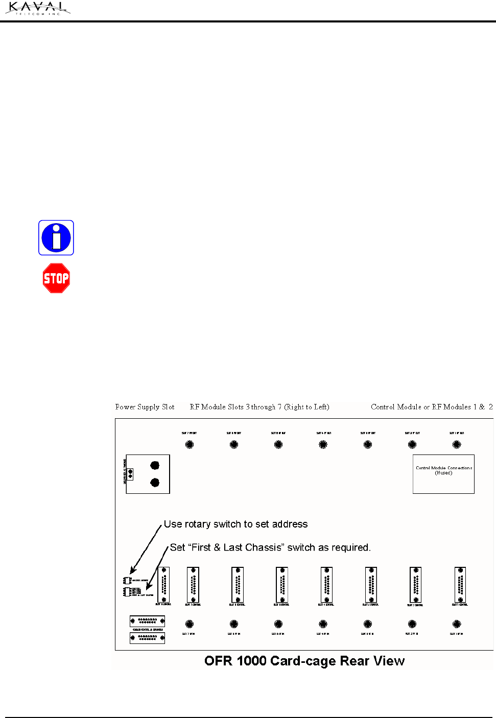
Card-cage Rear View
Switch Detail:
If Batteries are not to be installed with this unit, set the “Battery DIP Switch” to the
ON position. The switch is located on the lower left hand side of the back plane.
(See diagram below)
Battery connection
If Batteries are to be installed:
• Set the “Battery DIP Switch” to the OFF position. The switch is located on the left
hand side of the back plane. (See diagram below)
• Make sure the batteries have been correctly sized, (See section on sizing
Batteries)
• Make sure that the batteries have been properly mounted (See Battery
Manufacturer’s Installation Instructions)
Battery
CHASSIS ADDRESS
BATTERY
NOT USED
NOT USED
FIRST & LAST CHASSIS
LINKnet™ ! USER MANUAL DCM000000008
Printed: 00.03.22,09:08
Revision Date:3/22/00 15
• Connect the Battery Connect Wiring Harness to the Battery end, and then connect
the other end to the plug in the upper left of the rear of the Card-Cage (See
diagram below)
• Calculate the required Charging Time to ensure the Batteries will be charged prior
to system testing. (See section on sizing Batteries)
Slide the modules into any of the vacant card-cage slots. Make sure that the module
is aligned with both of the upper and lower guide tracks on the card-cage, and that
the module is sliding in straight. The edge connector and the antenna connectors at
the rear of the module must be seated securely and evenly. Tighten the retaining
screws to secure the module. The Module is now ready for testing. (See Power On
Self-Test)
It is not necessary to power down the system to insert or remove RF modules, as
each module is designed with “Hot Swap” capabilities.
Do not force the module into position. It should slide in with little or no force. If the
module resists, remove it and inspect the slides and the connectors. If still unable to
insert the module contact KAVAL TELECOM INC.
Additional Modules
Additional modules may be added to the LINKnet™ card-cage at any time. It is not
necessary to power down the system to insert or remove modules.
Additional LINKnet™ card-cages
RF Modules
Expanding the System
LINKnet™ ! USER MANUAL DCM000000008
Printed: 00.03.22,09:08
Revision Date:3/22/00 16
Additional card-cages can be cascaded or “Daisy Chained” together with a Kaval
Model # CAB000000056 Expansion cable. Up to 15 cables can be used to connect
up to 16 LINKnet™ card-cages. The nominal maximum cable length is 150 feet but,
under certain conditions, a longer span may be possible, contact KAVAL TELECOM
INC. for assistance.
If 16 LINKnet™ card-cages are connected together the total system capacity is 110
RF modules without the optional Controller Module.
A separate power supply module (PS400A) and battery reserve (if desired) must be
installed for each card-cage as well. Only one (optional) Controller Module per
system is necessary.
Card-cage ID number
Each enclosure must have a unique Card-cage ID number; set by the rotary switch
located on the lower left hand side of the back plane.
If the system has only one card-cage this switch can be left at the default setting
(zero).
Group Termination
The first and last LINKnet™ card-cages must have the termination switch set to ON.
The switch is located in the lower left hand side of the back plane.
If the system has only one or two card-cages the switch can be left at the default
setting (ON).
Pins 2 & 3 of the DB15 “Control Port connector & Expansion cable connector”
connect to a dry, normally open, relay contact rated for 1 Amp at 28 Vdc. The
contacts will close if any of the modules in any of the LINKnet™ card-cages fault,
and will remain closed until the fault is corrected.
Because the LINKnet™ Expansion cable uses the same connector, this signal must
be taken from the un-used connector on either the first or last panel.
External fault
indication
LINKnet™ ! USER MANUAL DCM000000008
Printed: 00.03.22,09:08
Revision Date:3/22/00 17
Battery connection
Installing the software
Each RF module has a number of built in changeable parameters that may be
changed in the field directly by using the optional Controller Module. If the Controller
Module is not used, then these parameters may be changed by running custom
software on an external PC running Windows 95/98/NT, connected through the
CONTROL PORT CONNECTOR for each module, on the rear of the LINKnet™
card-cage. The software will be shipped on a disk, (optionally, it may be delivered
electronically over the internet), with its own install program.
From the Windows START button’s RUN Menu, Use the BROWSE button to find
the SETUP program on the disk, and follow the on screen instructions. When set-up
is complete, there will be a KAVAL TELECOM INC. icon on the desktop.
Cable connections
The rear of the LINKnet™ card-cage has a CONTROL PORT CONNECTOR for
each of the plug-in module bays. In order to change the parameters of a specific
card, the CONTROL PORT CONNECTOR for that card must be located.
The optional KAVAL TELECOM INC. # CAB000000057 cable will connect the
desired female DB15 CONTROL connector with the RS-232 Serial Port on the PC.
CONTROL connectors are NOT DIRECTLY RS-232 compatible. Use only KAVAL
TELECOM INC. supplied cables to connect with them. Using standard RS232
adapters may cause damage to the module or PC.
System Configuration
Programming
LINKnet™ ! USER MANUAL DCM000000008
Printed: 00.03.22,09:08
Revision Date:3/22/00 18
CONTROL CONNECTOR PINOUT
(FEMALE DB15)
PIN USAGE NOTES
2 & 3 Normally Open Fault Relay Dry
Contacts (1A, 28 VDC max.)
Per Module fault indication. Not
the same as the signal on the
expansion cable connector.
10 Transmit
11 Receive
15 Ground
RS-232 compatible signals for
connection to a PC using
CAB000000057 cable.
6 SIG
7 TX Disable
8 Ground
Module Interconnection for
special application. Consult
factory.
1,4,5,9,12,13,14 Reserved, Do Not Use.
Running the program
The software allows a terminal emulation program to access the digital information
stored in the module. This same program will be used to modify the parameters in
every type of module in the system. Since not all modules will have the same types
or values for parameters, it is very important that the user know the type of module
to be changed, the types of parameters that may be changed, the range of values,
the current values of the parameters, and finally the target or desired values for
those parameters. To facilitate this, these values are included in this manual in the
section for each type of module, and KAVAL TELECOM INC. recommends that any
modified values be recorded in that section of the manual.

LINKnet™ ! USER MANUAL DCM000000008
Printed: 00.03.22,09:08
Revision Date:3/22/00 19
Not yet approved for distribution
7. MAINTENANCE

LINKnet™ ! USER MANUAL DCM000000008
Printed: 00.03.22,09:08
Revision Date:3/22/00 20
Not currently available
8. TROUBLE SHOOTING

LINKnet™ ! USER MANUAL DCM000000008
Printed: 00.03.22,09:08
Revision Date:3/22/00 21
The following is KAVAL TELECOM INC.’s standard warranty. Purchase agreements
may stipulate additional or alternate conditions and terms. Any specific contractual
warranties shall supersede the following section.
KAVAL TELECOM INC. products are warranted to be free from defects in
workmanship or materials for a period of one (1) year from the date of shipment to
the original purchaser. This warranty supersedes and voids any and all other
warranties expressed or implied.
In no event shall KAVAL TELECOM INC. be liable for incidental or consequential
damages arising from the use, misuse, failure to operate, or improper operation of
any KAVAL TELECOM INC. product or product accessory. Specifically excluded
from this warranty is any claim of merchantability or fitness for a particular purpose
or application.
Because most radio communication systems are unique, rely upon equipment not
manufactured by KAVAL TELECOM INC. and require proper system design, any of
signal coverage, reliability of communications or other system performance is
specifically and expressly excluded unless a separate expressed written agreement
to such effect, executed by an authorized officer of KAVAL TELECOM INC., has
been entered into.
This warranty is void if the product has been subject to: misuse; neglect; accidental
damage; damage of a purely cosmetic nature; misapplication; extreme
environmental conditions; unauthorized repair or alteration.
If warranty repair is required, KAVAL TELECOM INC. will repair or replace the
defective product, and KAVAL TELECOM INC.s liability will be limited to one of
these remedies. KAVAL TELECOM INC. will endeavor to complete warranty
performance within 14 working days.
All returns, including warranty returns, must have a valid Return Material
Authorization (RMA) number.
Customers must contact KAVAL TELECOM INC. before shipping any product for
warranty service and obtain a Returned Materials Authorization and detailed
shipping instructions. Shipping charges, for shipment of product to KAVAL
TELECOM INC. for warranty service, will be borne by KAVAL TELECOM INC. if a
defect covered by warranty is found and warranty service is required. At KAVAL
TELECOM INC.’s sole discretion, a service fee will be charged if a returned unit is
found by KAVAL TELECOM INC. not to be defective, or defective for a reason that
voids this warranty. Return shipping charges shall, in such case, be the
responsibility of the customer.
9. WARRANTY INFORMATION
Product Warranty
RMA Procedure
LINKnet™ ! USER MANUAL DCM000000008
Printed: 00.03.22,09:08
Revision Date:3/22/00 22
Part Numbers referred to in this Manual
Number Description
CAB000000055 Battery Connect Cable
CAB000000056 Expansion Cable
CAB000000057 Control Connector
CAB000000058 AC Power Cable
DCM000000008 This Manual
Appendix A: Quick Reference
Part Numbers