Proxim Wireless US58-S60 Tsunami Subscriber Unit User Manual SS SU Manual v001ss
Proxim Wireless Corporation Tsunami Subscriber Unit SS SU Manual v001ss
Contents
- 1. User Manual
- 2. Installation Manual
User Manual

WESTERN MULTIPLEX CORPORATION
Installation and Maintenance Manual
Subscriber Unit
Multipoint
MAN 40XXX-001d1
SS


TSUNAMI MULTIPOINT
ii
Revisions:
September 2001 Draft
October FCC submittal
December Spread Spectrum Version

WESTERN MULTIPLEX CORPORATION
Tsunami Point-to-Multipoint
2001
Western Multiplex Corporation
1196 Borregas Avenue
Sunnyvale, California 94089 USA
Phone +1 408 542 5200 • Fax +1 408 542 5300
http://www.wmux.com
ftp://ftp.wmux.com/products/

TSUNAMI MULTIPOINT
ii
NOTICE: CAREFULLY READ THE FOLLOWING LIMITED WARRANTY AND LIMITATION OF LIABILITY
(THE “LIMITED WARRANTY”). BY USING THE WESTERN MULTIPLEX EQUIPMENT
INCLUDED WITH THIS LIMITED WARRANTY, YOU AGREE TO THE TERMS AND CONDITIONS
CONTAINED IN THIS LIMITED WARRANTY. IF YOU DO NOT AGREE TO THESE TERMS AND
CONDITIONS, RETURN THE WESTERN MULTIPLEX EQUIPMENT TO WHERE IT WAS
PURCHASED OR LEASED WITHIN THIRTY (30) DAYS OF RECEIPT FOR A FULL REFUND.
1. LIMITED EQUIPMENT WARRANTY
1.1 For the applicable Warranty Period (as defined in Paragraph 1.2 below) Western Multiplex
warrants that the hardware manufactured by Western Multiplex and initially purchased or leased
from one of Western Multiplex’s authorized resellers or distributors by the original end-user (“you”)
for your personal use and not for resale (the “Equipment”) (a) substantially conforms to the
specifications contained in the most recent version of the manual for the model of the Equipment
purchased or leased by you (the “Equipment Specifications”) and (b) is free from defects in
materials and workmanship. This Limited Warranty only applies to the Equipment and its
preloaded firmware. This Limited Warranty does not apply to any software (or its associated
documentation), whether preloaded with the Equipment, installed subsequently or otherwise
(“Software”), nor does it apply to any firmware revision that is not originally preloaded on the
Equipment at the time the Equipment is purchased or leased. The Software is licensed to you
pursuant to the software license agreement that accompanied the Software and is subject to the
terms, including the limited warranty and limitation of liability, contained in that license agreement.
Western Multiplex has no obligation to repair or replace Software under this Limited Warranty.
1.2 This Limited Warranty shall start on the date that the Equipment is first shipped to you (the
“Shipping Date”) and shall end:
(a) for all unlicensed radio products which are point-to-multi-point products, one (1) year after
the Shipping Date;
(b) for all accessories, one (1) year after the Shipping Date; and
(c) for all unlicensed radio products (except point-to-multi-point products) and for all licensed
digital microwave radio products, two (2) years after the Shipping Date (in each case, the
“Warranty Period”).
1.3 Nothing in this Limited Warranty affects any statutory rights of consumers that cannot be waived
or limited by contract.
2. LIMITED WARRANTY EXCLUSIONS AND LIMITATIONS.
2.1 The Limited Warranty covers customary and intended usage only.
2.2 Western Multiplex does not warrant, and is not responsible for damage, defect or failure caused
by any of the following:
(a) Any part of the Equipment having been modified, adapted, repaired, or improperly
installed, operated, maintained, stored, transported or relocated by any person other than
Western Multiplex personnel or a Western Multiplex authorized service agent;
(b) External causes, including electrical stress or lightning, interference caused by other
radios or other sources, unsuitable physical or operating environment and use in
conjunction with incompatible equipment or accessories;
(c) Cosmetic damage, including all damage to the surface of the Equipment;

iii
(d) Acts of God, fires, floods, wars, terrorist acts, sabotage, civil unrest, labor disputes or
similar events, actions or hazards; and
(e) Accidents, negligence, neglect, mishandling, abuse or misuse, other than by Western
Multiplex personnel or a Western Multiplex authorized service agent.
2.3 The Limited Warranty does not apply to the following parts of the Equipment, which are not
manufactured by Western Multiplex, but which may be otherwise covered by an original
manufacturer’s warranty:
(a) antenna systems, including coaxial cable, wave guide, connectors, flex sections, mounts,
and other parts of the antenna system and installation materials;
(b) rack mounted equipment, which is not manufactured by Western Multiplex but which may
be assembled, wired and tested at Western Multiplex’s factory or supplied as part of a
system, including orderwire items, channel banks, multiplexers, fuse/alarm panels and
remote alarm items; and
(c) all equipment which is not included in Western Multiplex’s specifications.
2.4 Unless otherwise specified, equipment not manufactured by Western Multiplex is provided “AS IS”
AND WITHOUT WARRANTIES OF ANY KIND. Please refer to the original manufacturer’s
warranty, if any.
2.5 Any technical or other support provided for the Equipment by Western Multiplex, such as
telephone assistance or assistance regarding installation, is provided “AS IS” AND WITHOUT
WARRANTIES OF ANY KIND.
3. REPLACEMENT, REPAIR AND RETURN PROCESSES.
3.1 To request service under the Limited Warranty:
(a) You must, within the applicable Warranty Period, promptly notify Western Multiplex of the
problem with the Equipment, provide the serial number of the Equipment, and provide
your contact information during business hours, by contacting Western Multiplex by
telephone at 408-542-5390, by e-mail at support@wmux.com, or by mail to Support,
Western Multiplex Corporation, 1196 Borregas Avenue, Sunnyvale, California 94089,
during the business hours of 8:00 a.m. to 5:00 p.m., Pacific Time, Monday through Friday,
excluding holidays. This notice is effective when received by Western Multiplex during the
business hours referenced above.
(b) Western Multiplex shall, at its sole option, either resolve the problem over the telephone
or provide you with a returned materials authorization number (“RMA Number”) and the
address of the location to which you may ship the Equipment at issue.
(c) If the problem is not resolved over the telephone, and Western Multiplex gives you an
RMA Number, you must, within ten (10) business days of your receipt of an RMA Number
if you are located within the borders of the United States and within thirty (30) days of your
receipt of an RMA Number if you are located beyond the borders of the United States, at
your cost, ship the Equipment to the location specified by Western Multiplex. The
Equipment must be shipped in its original or equivalent packaging. You must also attach a
label to each item of Equipment you are returning, which must include the following
information: the RMA Number, a description of the problem, your return address and a
telephone number where you can be reached during business hours. You must also
include with the Equipment a dated proof of original purchase. YOU ARE RESPONSIBLE

TSUNAMI MULTIPOINT
iv
FOR ALL EQUIPMENT UNTIL WESTERN MULTIPLEX RECEIVES IT, AND YOU ARE
RESPONSIBLE FOR ALL SHIPPING, HANDLING AND INSURANCE CHARGES,
WHICH MUST BE PREPAID.
(d) Western Multiplex is not responsible for Equipment received without an RMA Number and
may reject the return of such Equipment. Western Multiplex is also not responsible for any
of your confidential, proprietary or other information or data contained in Equipment you
return to Western Multiplex. You should remove any such information or data from the
Equipment prior to making any return to Western Multiplex.
(e) The replacement or repair of Equipment in locations outside of the United States may vary
depending on your location.
(f) FAILURE TO FOLLOW THE PROCEDURES FOR RETURNS LISTED ABOVE MAY
VOID THE LIMITED WARRANTY.
3.2 If the Equipment does not function as warranted, as determined by Western Multiplex in its sole
discretion, Western Multiplex shall either repair or replace the returned Equipment at its sole
option.
(a) The replacement item may be new or refurbished. All parts removed from repaired
Equipment and all returned Equipment that is replaced by Western Multiplex become the
property of Western Multiplex.
(b) Western Multiplex shall, at its cost (which shall not include international customs, freight
forwarding, or associated fees) ship the repaired or replacement Equipment to any
destination, by carrier and method of delivery chosen by Western Multiplex, in its sole
discretion. Western Multiplex will not pay, and you will be solely responsible for, any
international customs, freight forwarding, or other associated fees related to such
shipment. If you request some other form of conveyance, such as express shipping, you
must pay the cost of return shipment.
3.3 Equipment which is repaired or replaced by Western Multiplex under this Limited Warranty shall
be covered under all of the provisions of this Limited Warranty for the remainder of the applicable
Warranty Period or ninety (90) days from the date of shipment of the repaired or replacement
Equipment, whichever period is longer.
4. LIMITATIONS OF RIGHTS AND DISCLAIMER OF OTHER WARRANTIES
4.1 THE LIMITED WARRANTY CONTAINS LIMITATIONS ON YOUR RIGHTS AND REMEDIES
AGAINST WESTERN MULTIPLEX. YOU ACKNOWLEDGE HAVING READ, UNDERSTOOD
AND AGREED TO THOSE LIMITATIONS.
4.2 Western Multiplex does not warrant that the functions contained in the Equipment will meet your
requirements or that any Equipment’s operation will be uninterrupted or error free. REPAIR OR
REPLACEMENT OF THE EQUIPMENT AS PROVIDED HEREIN IS THE EXCLUSIVE REMEDY
AVAILABLE TO YOU, AND IS PROVIDED IN LIEU OF ALL OTHER WARRANTIES, WHETHER
ORAL OR WRITTEN, EXPRESS OR IMPLIED, INCLUDING, BUT NOT LIMITED TO, THE
IMPLIED WARRANTIES OF MERCHANTABILITY AND FITNESS FOR A PARTICULAR
PURPOSE AND NONINFRINGEMENT OF THIRD PARTY RIGHTS. ALL OTHER WARRANTIES
ARE EXCLUDED TO THE FULLEST EXTENT PERMITTED BY LAW AND EXCEPT FOR THE
LIMITED WARRANTY PROVIDED HEREIN, THE EQUIPMENT IS PROVIDED “AS IS”. No

v
dealer, agent, or employee is authorized to make any modification, extension, or addition to the
Limited Warranty.
5. LIMITATION OF LIABILITY
5.1 WESTERN MULTIPLEX SHALL NOT BE LIABLE TO YOU FOR INDIRECT, SPECIAL,
PUNITIVE, INCIDENTAL OR CONSEQUENTIAL DAMAGES (INCLUDING, BUT NOT LIMITED
TO, LOST PROFITS) OF ANY KIND SUSTAINED OR INCURRED IN CONNECTION WITH, OR
RELATED TO, THE EQUIPMENT OR YOUR USE OF THE EQUIPMENT REGARDLESS OF
THE FORM OF ACTION OR NATURE OF THE CLAIM (INCLUDING, BUT NOT LIMITED TO,
BREACH OF WARRANTY, BREACH OF CONTRACT, TORT, NEGLIGENCE OR STRICT
LIABILITY) AND WHETHER OR NOT SUCH DAMAGES ARE FORESEEABLE, AND EVEN IF
WESTERN MULTIPLEX HAS BEEN ADVISED OF THE POSSIBILITY OF SUCH LOSS. IN NO
CASE WILL WESTERN MULTIPLEX BE LIABLE FOR ANY REPRESENTATION OR
WARRANTY MADE TO, OR BY, ANY THIRD PARTY BY, OR TO, YOU OR ANY OF YOUR
AGENTS. WESTERN MULTIPLEX’S TOTAL LIABILITY TO YOU SHALL NOT EXCEED THE
AMOUNT PAID BY YOU FOR THE EQUIPMENT AT ISSUE. This limitation of liability also applies
to Western Multiplex’s authorized resellers and distributors and it is the maximum amount for
which Western Multiplex and the reseller or distributor who sold you the Equipment are collectively
responsible.
6. DISCLAIMERS
6.1 This Limited Warranty gives you specific legal rights, and you may also have other rights that vary
from jurisdiction to jurisdiction. Some jurisdictions do not allow the exclusion or limitation of
incidental or consequential damages, may not allow limitations on how long an implied warranty
lasts, and may not allow provisions that permit a warranty to be voided. Consequently, such
limitations and exclusions may not apply to you. In the event an implied warranty cannot be
excluded under the law of the applicable jurisdiction, it is limited in duration to the applicable
Warranty Period.
7. MISCELLANEOUS
7.1 Transfer. You may not transfer or assign this Limited Warranty. Any transfers or assignments
made in violation of this Paragraph shall be void.
7.2 Governing Law. The Limited Warranty shall be governed by the laws of the State of California,
without reference to its conflicts of laws provisions. The United Nations Convention on the
International Sale of Goods shall not apply to this Limited Warranty.
7.3 Arbitration/Dispute Resolution. Any dispute, controversy or claim arising out of or in connection
with the Equipment shall be finally resolved by arbitration under the International Arbitration Rules
of the American Arbitration Association. The place of arbitration shall be Sunnyvale, California.
The number of arbitrators shall be one. The language of arbitration shall be English.
7.4 Indemnification. You shall indemnify and hold harmless Western Multiplex (including its directors,
officers, employers and agents) against any and all claims (including all expenses and reasonable
attorneys’ fees) arising from or relating to the operation of the Equipment due to, in whole or in
part, your (including your agents’ or employees’) negligence, gross negligence or misconduct.


i
Table of Contents
1 INTRODUCTION ............................................................................................................................................. 1-1
PRODUCT HIGHLIGHTS ......................................................................................................................................... 1-2
KEY FEATURES...................................................................................................................................................... 1-3
HOW TO USE THIS MANUAL ........................................................................................................................................ 1-3
SAFETY INSTRUCTIONS ................................................................................................................................................ 1-4
2 SYSTEM OVERVIEW ..................................................................................................................................... 2-1
SITE PLANNING CONSIDERATIONS............................................................................................................................... 2-2
General Considerations........................................................................................................................................... 2-2
Weather .................................................................................................................................................................... 2-3
Antennas................................................................................................................................................................... 2-5
Path Planning .......................................................................................................................................................... 2-6
SPECIFICATIONS ........................................................................................................................................................... 2-7
SYSTEM ................................................................................................................................................................... 2-7
STANDARDS COMPLIANCE AND INTERFACES................................................................................................ 2-8
CONFIGURATION AND MANAGEMENT ............................................................................................................ 2-8
POWER /ENVIRONMENT /SAFETY ...................................................................................................................... 2-8
PHYSICAL DIMENSIONS ...................................................................................................................................... 2-8
MOUNTING (INSTALLATION).............................................................................................................................. 2-8
3 SET-UP PROCEDURE..................................................................................................................................... 3-1
Important Configuration Notes ............................................................................................................................... 3-1
Unpacking the System.............................................................................................................................................. 3-1
Mechanical Considerations – Mounting Units ....................................................................................................... 3-3
Location Selection ................................................................................................................................................... 3-4
Pole Mounting ......................................................................................................................................................... 3-4
PICTURES HELPFUL FOR INSTALLATION....................................................................................................................... 3-5
SOFTWARE INSTALLATION........................................................................................................................................... 3-7
Subscriber Unit Configuration ................................................................................................................................ 3-7
To determine connection with host and/or Internet .............................................................................................. 3-11
HELP: .................................................................................................................................................................... 3-11
4 SU CONNECTIONS ......................................................................................................................................... 4-1
SU Power Adapter (Power Brick) ........................................................................................................................... 4-1
SU Installation Kit ................................................................................................................................................... 4-1
INTERFACES.................................................................................................................................................................. 4-2
Broadband Air Interface.......................................................................................................................................... 4-2
ODU (J1) to Power Adapter Interface (J1)............................................................................................................. 4-2
Alternative Method of Connection........................................................................................................................... 4-3
Power Adapter Ethernet Port (J2) .......................................................................................................................... 4-4
AC Power Input (P1) ............................................................................................................................................... 4-4
5 TROUBLESHOOTING.................................................................................................................................... 5-1
Regular Maintenance .............................................................................................................................................. 5-1
Problem – Solution Section ..................................................................................................................................... 5-1
REPAIR AND RETURN INSTRUCTIONS AND POLICY STATEMENT................................................................................. 5-4
INDEX ......................................................................................................................................................................... 5-5

TSUNAMI MULTIPOINT
ii
Figures
FIGURE 2-1: EACH HUB IS MADE UP OF ONE TO SIX BASE STATIONS AND MULTIPLE REMOTES(SUS) ......................... 2-1
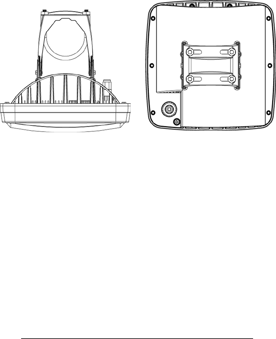
FIGURE 2-2: SUBSCRIBER UNIT ODU TOP AND BACK VIEWS ........................................................................................ 2-9
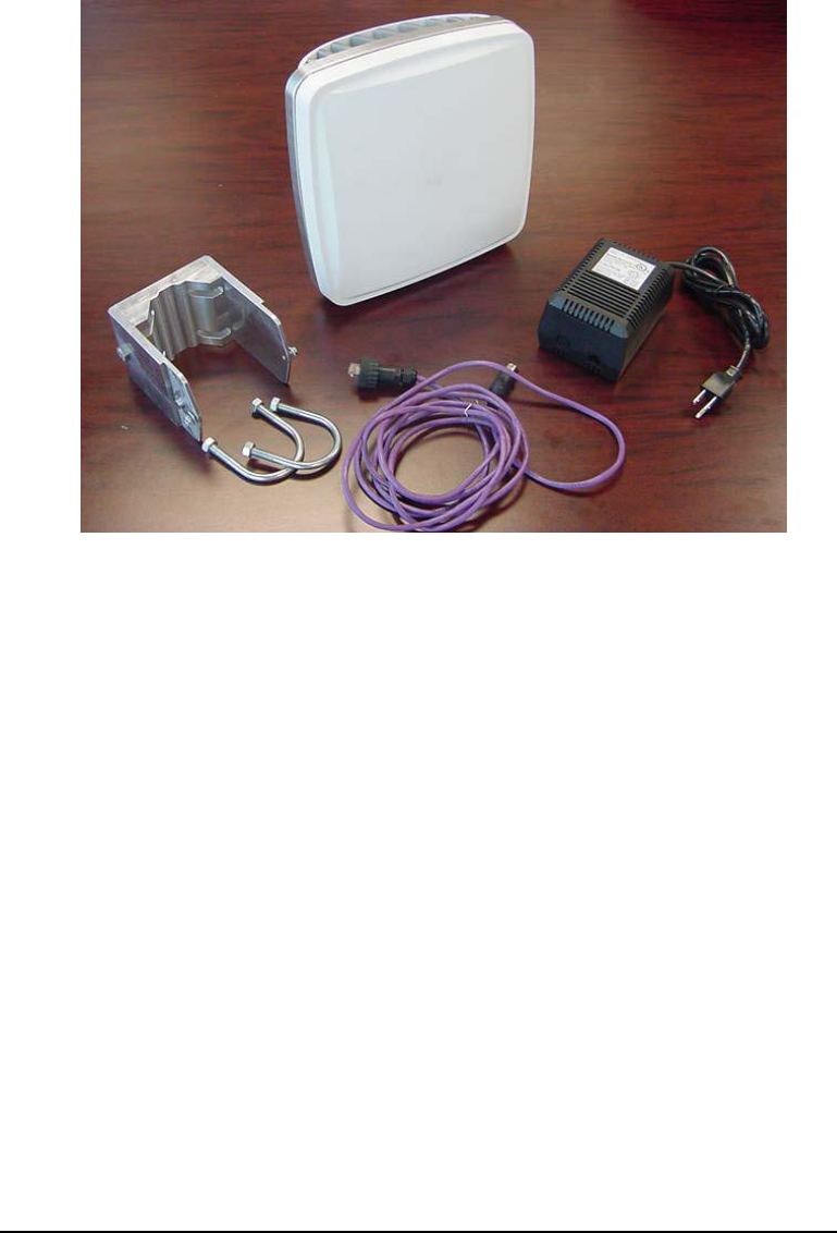
FIGURE 3-1: SUBSCRIBER UNIT KIT................................................................................................................................. 3-2
FIGURE 3-2: SUBSCRIBER ODU MOUNTING ................................................................................................................... 3-3
FIGURE 3-3: ODU BACKSIDE CABLE AND GROUNDING DETAIL ...................................................................................... 3-4
FIGURE 4-1: DIAGRAM OF POWER ADAPTER/BRICK ....................................................................................................... 4-1
FIGURE 4-3: SUBSCRIBER UNIT CABLE DETAIL .............................................................................................................. 4-2
FIGURE 4-4: ODU INTERFACE (J1) .................................................................................................................................. 4-2
FIGURE 4-5: POWER ADAPTER INTERFACE (J1) .............................................................................................................. 4-3
FIGURE 4-6: POWER ADAPTER AND ODU CONNECTORS................................................................................................ 4-4
FIGURE 4-7: REPRESENTATIVE NETWORKING CONFIGURATIONS................................................................................... 4-6
Tables
TABLE 4-1: ODU TO POWER ADAPTER INTERFACE CABLE DEFINITION........................................................................ 4-4
TABLE 4-2: ETHERNET PORT INTERFACE DEFINITION. ................................................................................................... 4-4

TSUNAMI MULTIPOINT
1-1
1 Introduction
sunami Multipoint is a point-to-multipoint outdoor wireless system offering a
high-capacity alternative to wired data networks. Using IP packet radio
transmitters, standard Ethernet interfaces, and an easy to-deploy design, the
Tsunami Multipoint system enables high-speed network connections to
multiple Ethernet switches, routers or PCs from a single location. With Tsunami
Multipoint, the system avoids the delays and costs associated with wired connections
such as DSL, cable modems, and leased T-1/E-1 lines. Tsunami Multipoint eliminates
wire/fiber installation costs and recurring monthly fees - delivering carrier-class
performance.
Tsunami Multipoint systems consist of one or more Subscriber Units that
communicate with a Base Station to provide high-performance wireless network
connections.
EXTEND OR ENHANCE YOUR NETWORK OVERNIGHT
With Tsunami Multipoint, there are no DSL, cable, or leased-line hassles to negotiate.
You no longer have to worry about man-made barriers to overcome. Easy installation
and operation allow network planners to quickly deploy up to 30 Mbps capacity
between locations, making it the ideal solution for:
Establishing high-speed connections between Internet Service Providers and their
customers
Organizations requiring high-capacity WAN connectivity between multiple buildings or
campuses
Organizations or service providers seeking network redundancy for mission critical wired
connections
Chapter
1
T

TSUNAMI MULTIPOINT
1-2
ABOUT THE TSUNAMI PRODUCT FAMILY
The Tsunami family of Ethernet bridges provides wireless solutions that meet the
growing demand for transparent and reliable high-speed network interconnectivity.
In addition to Tsunami Multipoint for point-to-multipoint connections, the Tsunami
product line includes the following point-to-point offerings:
Tsunami 10BaseT, a cost-effective, high-capacity alternative to multiple wireline T1
connections.
Tsunami 100BaseT/F, a cost-effective, high-capacity alternative to wireline DS3
connections.
Tsunami 1000BaseSX, the world's first Ethernet bridge to provide gigabit, wireless
connectivity for native IP connections.
PRODUCT HIGHLIGHTS
UP TO 180 MBPS PER HUB SITE
Speeds of 20 Mbps Time Division Duplex (TDD) per Base Station for optimal network
efficiency
Configurable upstream/downstream bandwidth to optimize desired throughput
Six Base Stations provide 360 degree coverage, delivering up to 180 Mbps per hub site
FAST AND EASY TO DEPLOY & MANAGE
Subscriber Unit simplicity enables self installation to minimize deployment costs
Audible beeper alignment eases installation
Subscriber Unit with integrated antenna connects to indoor power & networks using a
single CAT5 cable
"Over the air" software upgrades minimize subscriber unit maintenance costs
RAPID RETURN ON INVESTMENT
Rapid, easy deployment enables quick service activation, reduced costs and faster payback
High-capacity connection enables faster network traffic to deliver new service offerings

TSUNAMI POINT-TO-MULTIPOINT
1-3
PURE ETHERNET CONNECTIVITY
Operates in either Ethernet bridging, VPN or IP routing modes with direct connections to
PCs, Fast Ethernet switches & routers
Support for VLAN tagging (IEEE 802.1q)
KEY FEATURES
Flexible throughput rates: Time Division Duplex (TDD)
5.8 GHz license-exempt frequency band
Compliant with industry standards
Base Station provides 60 degree antenna - six Base Stations cover 360 degrees
Network management through SNMP & Java-based "Wireless Manager" software
Point-to-multi point communications from less than 1 mile/kilometer to more than 5
miles/ 8 kilometers
How to Use This Manual
The “icon key” at left will be used to “highlight” specific text
to call particular attention to it. Where specific emphasis needs
to be placed, these icons will direct you to other information or
particular areas where additional information can be found.
ICON KEY
Information
Suggestion
Caution
Note
Write this down

TSUNAMI MULTIPOINT
1-4
Safety Instructions
IMPORTANT
This product has been evaluated to the U.S. and Canadian (Bi-National) Standard for
Safety of Information Technology Equipment, Including Electrical Business
Equipment, CAN/CSA C22.2, No. 950-95 * UL 1950, Third Edition, including
revisions through revision date March 1, 1998, which are based on the Fourth
Amendment to IEC 950, Second Edition. In addition, this product was also evaluated
to the applicable requirements in UL 1950, Annex NAE.
WARNING - This unit is intended for installation in a Restricted Access location in
accordance with Articles 110-18, 110- 26, and 110-27 of the United States National
Electric Code ANSI/NFPA 70.
This equipment should be installed in accordance with Article 810 of the United States
National Electrical Code.
When installed, this equipment is intended to be connected to a Lightning/Surge
Protection Device that meets all applicable national Safety requirements.
Equipment is to be used and powered by the type of power source indicated on the
marking label only.
This product is intended to be connected to an AC power source which must be
electrically isolated from any ac sources and reliably earthed. Only an AC power
source that complies with the requirements in the Standard for the Safety of
Information Technology Equipment, Including Electrical Business Equipment,
CAN/CSA C22.2, No. 950-95 * UL 1950, Third Edition, can be used with this
product. A 15-Amp circuit breaker is required at the power source. In addition, an
easily accessible disconnect device should be incorporated into the facility wiring.
Always use copper conductors only for all power connections.
WARNING - This equipment is intended to be earthed. Use only the power supply
provided by Western Multiplex and be sure the ground pin is connected to an earthing
conductor between the unit’s earthing terminal and your earthing point.
Do not apply power to the equipment when the cable between the power source
(Power Brick or Block) and the Out Door Unit is not yet connected properly.
Servicing of this product should be performed by trained personnel only. Do not
disassemble this product. By opening or removing any covers you may expose
yourself to hazardous energy parts. Incorrect re-assembly of this product can cause a
malfunction, and/or electrical shock when the unit is subsequently used.

TSUNAMI MULTIPOINT
1-5
Do not insert objects of any shape or size inside this product. Objects may contact
hazardous energy parts that could result in a risk of fire or personal injury.
NOTE:
This equipment has been tested and found to comply with the limits for a Class B
digital device, pursuant to Part 15 of the FCC Rules. These limits are designed to
provide reasonable protection against harmful interference in a residential installation.
This equipment generates, uses and can radiate radio frequency energy and, if not
installed and used in accordance with the instructions, may cause harmful
interference to radio communications. However, there is no guarantee that
interference will not occur in a particular installation. If this equipment does cause
harmful interference to radio or television reception, which can be determined by
turning the equipment off and on, the user is encouraged to try to correct the
interference by one or more of the following measures:
• Reorient or relocate the receiving antenna.
• Increase the separation between the equipment and receiver.
• Connect the equipment into an outlet on a circuit different from that to which the
receiver is connected.
• Consult the dealer or an experienced radio/TV technician for help.
CAUTION
The outdoor units of the Tsunami Multipoint products must be fixed mounted on
permanent structures with a separation distance of at least 1.5 meters from all
persons during normal operation.
CAUTION:
Changes or modifications not expressly approved by the party responsible for
compliance could void the user's authority to operate the equipment
CAUTION:
The operator of the Tsunami Multipoint Subscriber Unit is responsible of ensure that
the device is used exclusively for fixed point-to-point operations.
TSUNAMI MULTIPOINT
2-1
2 System Overview
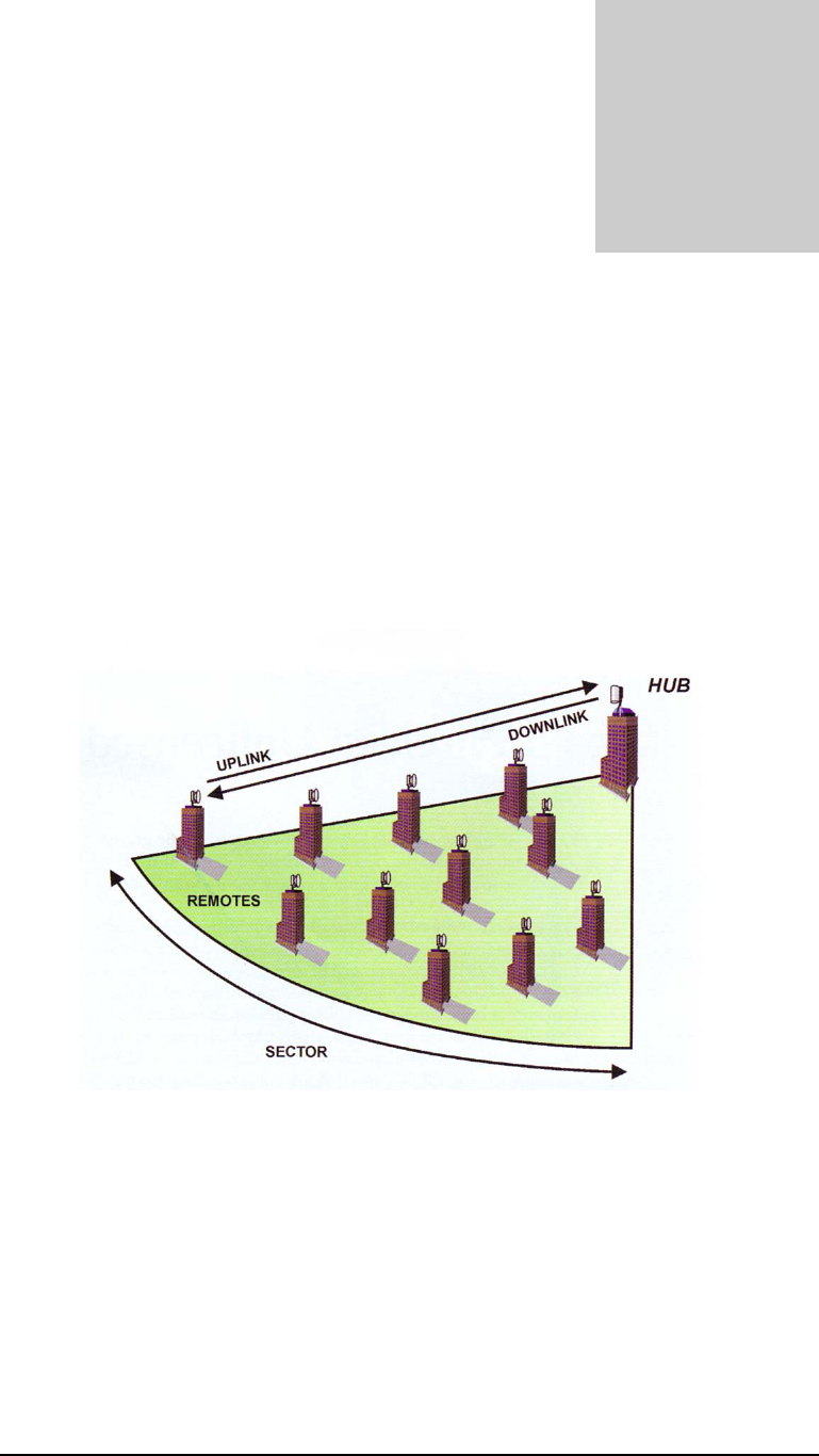
A system is made up of one to six Base Stations that make up a Hub (or cell) with
each Base Station communicating with their associated SUs (Subscriber Units).
Together, they provide a wide coverage, high-capacity system that transfers IP traffic
between the Hub and its multiple SUs. Each Hub has the ability to communicate in all
directions using up to six sectors of 60 degrees each. Each of the Hub’s six sectors has
the capability of communicating 20 Mbps in total bandwidth allowing a maximum of
180 Mbps per Hub.
Figure 2-1: Each HUB is made up of one to six Base Stations and multiple
remotes(SUs)
Uplink and Downlink, each SU communicates with a BSU in a coordinated manner so that
all other remotes within the BSU’s jurisdiction have an equal amount of time to coordinate
their data needs in both the uplink and downlink sessions. All SUs are very quickly handled on
a case by case basis giving the user, at the SU, the impression that they are in constant
communication with its Hub’s or BSU’s Sector.
.
Chapter
2

TSUNAMI MULTIPOINT
2-2
Site Planning Considerations
The installation of a wireless network requires much the same basic planning as any
wired network. The main difference is that the wireless signal requires some additional
planning. This planning includes RF path planning, site preparation, and installation of
outdoor components such as outdoor units, antennas, lightning protection devices,
and cabling suitable for outdoor conditions.
Although the technology implemented in this broadband fixed wireless system can
make use of multipath signals, reducing the effect of obstructions in the path, it is
important that the characteristics of the path be carefully examined. With this
knowledge, components and network requirements can be correctly planned for your
specific application.
This chapter provides insight into the planning necessary to prepare your site for your
broadband fixed wireless system.
General Considerations
A basic consideration is the physical location of the sites at each end of the link.
Because microwave signals travel in a straight line, a clear line of sight between
antennas is ideal. Frequently, however, the locations of the desired links are fixed.
When a clear line of sight cannot be achieved, you must plan accordingly.
Other general site considerations include:
a. Will a tower have to be constructed? Are permits required?
b. Possibility of future obstructions-Will trees grow high enough to interfere
with the signal? Are there plans to erect buildings between the sites that may
obstruct the path?
c. Availability of grounding-Good grounding is important in all areas of the
world, but in areas prone to lightning, it is especially critical.
d. Distance between the indoor portion of the system and the user’s network.
e. The SU may potentially be served by different Base Stations. Can the best
BSU access and available sighting location be determined prior to installation.
The planning of a wireless link involves collecting information and making decisions.
The following sections will help you determine which information is critical to the site
and will be an aid in the decision-making process.

TSUNAMI MULTIPOINT
2-3
Weather
It is important to research any unusual weather conditions that are common to the site
location. These conditions can include excessive amounts of rain, wind velocity or
extreme temperature ranges. If extreme conditions exist that may affect the integrity of
the radio link, it is recommended that these conditions be taken into consideration
early in the planning process.
RAIN
Except in extreme conditions, attenuation (weakening of the signal) due to rain does
not require serious consideration for frequencies up to the range of 6 GHz. When
microwave frequencies are at 10-12 GHz range or above, attenuation due to rain
becomes much more of a concern, especially in areas where rainfall is of high density
and long duration. The systems discussed in this manual operate at frequencies below
6 GHz, so rain is not a concern.
Temperature can adversely affect the radio link when such as temperature inversion,
or very still air accompanied by stratification. Temperature inversion can negate
clearances, and still air along with stratification can cause severe refractive or reflective
conditions, with unpredictable results. Temperature inversions and stratification can
also cause ducting, which may increase the potential for interference between systems
that do not normally interfere with each other. Where these conditions exist, it is
recommended that shorter paths and adequate clearances are used.
WIND
Any system components mounted outdoors will be subject to the effect of wind. It is
important to know the direction and velocity of the wind common to the site.
Antennas and their supporting structures must be able to prevent these forces from
affecting the antenna or causing damage to the building or tower on which the
components are mounted. Antenna designs react differently to wind forces, depending
on the area presented to the wind. This is known as wind loading.
Note For definitions of wind loading specifications for antennas and towers, refer
to TIA/EIA- 195 (for antennas) or TIA/EIA-222 (for towers) specifications.
LIGHTNING
The potential for lightning damage to radio equipment should always be considered
when planning a wireless link. A variety of lightning protection and grounding devices
are available for use on buildings, towers, antennas, cables, and equipment, whether
located inside or outside the site, that could be damaged by a lightning strike.
Lightning protection requirements are based on the exposure at the site, the cost of
link down-time, and local building and electrical codes. If the link is critical, and the
site is in an active lightning area, attention to thorough lightning protection and
grounding is critical.

TSUNAMI MULTIPOINT
2-4
LIGHTNING PROTECTION
To provide effective lightning protection, install antennas in locations that are unlikely
to receive direct lightning strikes, or install lightning rods to protect antennas from
direct strikes. Make sure that cables and equipment are properly grounded to provide
low-impedance paths for lightning currents. Install surge suppressors on adjacent
telephone lines and power lines.
Recommended is additional lightning protection in those regions that have extreme
lightning occurrences for cables leading to the wireless OutDoor Unit (ODU)
to/from the indoor power brick. This optional lightning protection should be placed
at points close to where the cable passes through the bulkhead into the building, as
well as near the ODU. Use the earthing screw at the ODU and use proper grounding.
CAT5 CABLE
When the entire control cable, from the building entrance to the ODU, is encased in
steel conduit, no surge arrestors are required. Otherwise, each control cable requires
one surge arrestor within two feet of the building entrance.
Note For installations with several radios, it may be more convenient to use a Type-
66 punch block with surge arrestors. A Type-66 punch block can accommodate up to
25 conductor pairs.
INTERFERENCE
An important part of planning your broadband fixed wireless system is the avoidance
of interference. Interference can be caused by effects within the system or outside the
system. Good planning for frequencies and antennas can overcome most interference
challenges.
Co-Channel and Adjacent Channel Interference
Co-channel interference results when another RF link is using the same channel
frequency. Adjacent-channel interference results when another RF link is using an
adjacent channel frequency. In selecting a site, a spectrum analyzer can be used to
determine if any strong signals are present at the site and, if they are, to determine how
close they are to the desired frequency. The further away from your proposed
frequency, the less likely they are to cause a problem.

TSUNAMI MULTIPOINT
2-5
Antennas
Antennas frequently play a key role in reducing the potential for interference. They
come in a variety of configurations that have different performance characteristics in
the areas of gain and directionality. Antennas that transmit/receive in all directions are
known as omni-directional, while those that transmit/receive in one specific direction
are categorized as directional. Antennas also vary in beamwidth, which is the aperture
to which they can “see” signals. Larger antennas typically provide narrower
beamwidths and can diminish interference from nearby transmitters by:
• Focusing RF energy from the intended destination
• Reducing the power of interfering sources not directly aligned to the antenna
Antennas: the narrower, the better
Tsunami Multipoint Ethernet Systems use integrated directional antennas that
transmit and receive a relatively narrow beamwidth of radio energy, improving system
performance by reducing the likelihood that surrounding RF clutter will interfere with
reception. The antennas with this system are directional and can not be detached.
Type: Flat-panel antenna
Beamwidth: 10-degree
Elevation: 10-degree
Even when other licensees are not an issue, if you are using a network deployment
using the "cell" approach, all these considerations are still important to reduce
interference between your own adjacent installations. Antennas are tuned to operate
on a specific group of frequencies. Tsunami Multipoint offers a variety of channel
plans that provide a flexible tool for overcoming present and future interference. Four
non-overlapping 20 MHz channels (six total directional channels) can be used to avoid
existing traffic in the 5.8 GHz frequency band. If one part of the 5.8 GHz spectrum is
occupied when Tsunami Multipoint is initially deployed, another frequency channel
can be selected to bypass the interfering signal. If interference arises after deployment,
another frequency channel plan can be selected to “steer around” the impacted
channel. Beamwidth and gain have been optimized in this equipment.
ANTENNA POLARIZATION
The Tsunami Multipoint system uses left-hand circular polarization. As a result, the
signal is successfully received regardless of the orientation of the antenna. Circular
polarization also provides protection against multipath degradation of the signal
quality.

TSUNAMI MULTIPOINT
2-6
TOWERS
When planning antenna placement, it might be necessary to build a free-standing
tower for the antenna. Regulations and limitations define the height and location of
these towers with respect to airports, runways, and airplane approach paths. These
regulations are controlled by the FAA. In some circumstances, the tower installations
must be approved by the FAA, registered with the FCC, or both.
To ensure compliance, review the current FCC regulations regarding antenna
structures. These regulations (along with examples) are on the FCC web site at
wwwfcc.gov/wtb/antenna/.
Path Planning
To get the most value from a wireless system, path planning is essential. In addition to
the fact that radio signals dissipate as they travel, many other factors operate on a
microwave signal as it moves through space. All of these must be taken into account,
because any obstructions in the path will attenuate the signal.
A link budget is a rough calculation of all known elements of the link to determine if
the signal will have the proper strength when it reaches the other end of the link. To
make this calculation, the following information should be considered.
A signal degrades as it moves through space. The longer the path, the more loss it
experiences. This free-space path loss is a factor in calculating the link viability. Free-
space path loss is easily calculated for miles or kilometers.
Availability represents the quality of a link. It is the ratio of the time that the link is
available to the total time. This serves as a guide to the service that you can expect, on
average, over a period of one year. Table 2-2 shows how percentage availability relates
to outage time per year.
Note: use the path planning tools located on the WMUX web site: www.wmux.com
Note You can lower the bit error rate (BER), resulting in greater reliability, by
reducing the data throughput or reducing the distance.
UNLICENSED FREQUENCIES-ISM
The FCC has identified the frequencies from 5.725 to 5.825 GHz as an Industrial,
Scientific, Medical (ISM) band. This band can be used by anyone without having to
obtain a license. However, you must use radio equipment that is "type approved" by
the FCC or local government for use within the specific band.
TSUNAMI MULTIPOINT
2-7
Specifications
Integrated antenna (LHCP, 21 dBi)
PRODUCT BURST_RATE LIMIT MODEL NUMBER
Subscriber Unit 20 Mbps 40100-XXx
BURST RATE D/L THROUGHPUT U/L THROUGHPUT
20 Mbps 9 Mbps 8 Mbps
Note: Above calculations are typical and based on a 50/50 down/link (D/L) up/link
(U/L) division of slots. SU throughput may be limited by a provider's Service Level
Agreement or other D/L U/L settings
TX POWER -48 to +15 dBm (into antenna port)
RECEIVER SENSITIVITY BURST-RATE THRESHOLD
20 Mbps -89 dBm
MAXIMUM DISTANCE FROM BASE STATION
BURST-RATE CLOS* NLOS**
20 Mbps 6 miles/10 km 3 miles/5 km
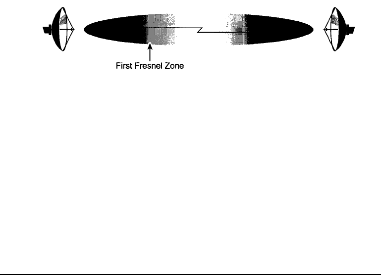
* Clear-Line-of-Site distance is calculated for 99.995% availability assuming no obstructions in the
first Fresnel zone.
** Near-Line-of-Site distance is for a typical installation with moderate multipath/shadowing due to
terrain and structures.
SYSTEM
Operating Frequency Range 5725-5825 MHz
Radio Access Method TDMA
Duplexing Time Division Duplex (TDD)
Integrated Antenna 21 dBi (10˚x10˚) LHCP
Frequency Channels 4 non-overlapping, 5 and 6 plans available
Regulatory Compliance FCC Part 15.247 (ISM)
IC RSS210

TSUNAMI MULTIPOINT
2-8
STANDARDS COMPLIANCE AND INTERFACES
Ethernet Interface 10/100BaseT
Ethernet Connector RJ45 female
Indoor-outdoor cable RJ45 (outdoor) & DIN(indoor)
over Category-5(UV) cable
Standards Compliance IEEE 802.1d Bridging Mode
IEEE 802.1q VLAN
CONFIGURATION AND MANAGEMENT
Configuration Automatic
Security Authentication, IP/MAC Filtering
Software Upgrades Over-the-air Subscriber Unit reprogramming
POWER /ENVIRONMENT /SAFETY
Electrical
Subscriber Unit 18 to 28 Volts DC, 0. 8 Amps
Power Brick 115 or 100-240 Volts AC
Operational Temperature 0º to 55º C (indoor), -33º to 65º C (outdoor)
Humidity 95% non-condensing (indoor)
5% to 100%, condensing (outdoor)
EIVIC FCC Class B
Safety UL-1950
Environmental Compliance ETS 300 019
PHYSICAL DIMENSIONS
Outdoor Unit
Size (WxHxD) 10.5x10.5x 6.8 inch/126.5x26.5x 17.4cm
Weight 10 lbs/ 4.5 kg
Power Brick (Indoor Unit)
Size (WxHxD) 3.6 x 5.1 x 2.6 inches/92 x 130 x 67 cm
Weight 2.7 lbs/1.2 kg
MOUNTING (INSTALLATION)
Subscriber Unit ODU Pole Mounting, 1.00-2.50" diameter
OPTIONAL ACCESSORIES
Wall mounting kit (contact factory)
Other cable lengths (50 & 100m cables)
TSUNAMI MULTIPOINT
2-9
Connector kit
U-Bolt options for different sized mounting poles
Figure 2-2: Subscriber Unit ODU Top and Back Views

TSUNAMI MULTIPOINT
3-1
3 Set-up Procedure
Please read this section completely before attempting to install any software, test or
operate this system.
Permanent damage to the equipment can result if directions are not followed
exactly as provided.
Important Configuration Notes
The Subscriber Unit (SU) does not normally require any configuration prior to
operation. The SU will automatically negotiate with the Base Station Unit when
sufficient signal strength is received in both directions to establish communications.
For custom configurations, the Subscriber Utility software, supplied on the CD,
provides the capability to configure and control the SU. The syntax of the data entry
must be followed exactly as shown. When a string of characters is shown in this
document with quotation marks around it (such as “ip”), do not type the quotation
marks. When the letter “x” is shown within the quotation marks, this represents a
number that the operator will select based on other factors. When the word (enter) is
shown, this indicates pressing of the Enter (or Return) key on your keyboard.
Wherever there are spaces shown in the syntax of a command, include these spaces.
Commands are case sensitive.
Unpacking the System
Pay close attention to how units are packed before unpacking.
SEE PHOTO BELOW AND NEXT PAGE FOR CLARIFICATION
Unpacking should be in the following steps:
a. Remove power supply units
b. Remove small metal brackets
Chapter
3
TSUNAMI MULTIPOINT
3-2
c. Remove all cables and small hardware
d. Remove SU
Figure 3-1: Subscriber Unit Kit
TSUNAMI MULTIPOINT
3-3
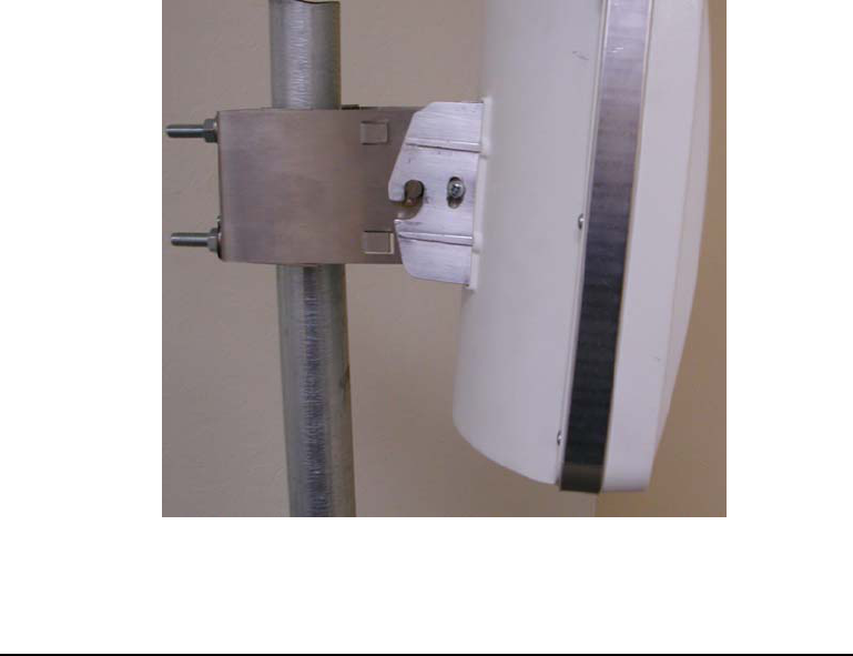
Mechanical Considerations – Mounting Units
The outdoor component of the Subscriber Unit (SU) is designed to directly mount a
pole. Using optional mounting brackets, the SU can be mounted to a wall or other flat
surface. Using the supplied U-bolts, the SU will mount to a 1-1/4 inch to 2 inch pole
diameter (outside diameter). To mount to pole diameters up to 3 inches, other U-bolt
sizes may be used. For mounting to a flat surface, attach mounting bracket to the SU
using bolts supplied, and then mount to flat surface using your own hardware.
For mounting directly to a 1-1/2 inch or 1-3/4 inch pole, first attach the supplied
mounting bracket to the pole using the U-bolt retainer. Then attach the SU to the
mounting bracket, and lock into position by tightening the 10-32 screws. See photos
below for detail. Connect the weatherproof RJ45 connector. The RJ45 connector
does not “click” into the receptacle; it is held into place by the screw-on cap.
The following U-Bolt kits enable mounting to other than a standard size pole:
U-BOLT, 1 – 1 1/2" SCH 40 PIPE, 5/16-18 THD, ZINC/STEEL
U-BOLT, 1 1/4 - 1 3/4" SCH 40 PIPE, 5/16-18 THD, ZINC/STEEL
U-BOLT, 1 1/2 - 2" SCH 40 PIPE, 5/16-18 THD, ZINC/STEEL
U-BOLT, 2 – 2 1/2" SCH 40 PIPE, 5/16-18 THD, ZINC/STEEL
U-BOLT, 2 1/2 - 3" SCH 40 PIPE, 5/16-18 THD, ZINC/STEEL
For mounting to a flat surface, attach mounting bracket to the CPE using bolts
supplied, and then mount to flat surface using your own hardware.
Figure 3-2: Subscriber ODU Mounting
TSUNAMI MULTIPOINT
3-4
Connect the supplied cable between the ODU (pictured above) and the power unit
mounted near your PC or network.
If it is necessary to cut the cable for routing use the optional connector replacement
kit. Follow the instructions in section 4.
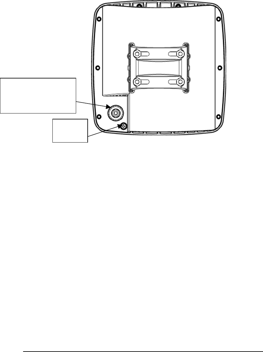
Figure 3-3: ODU backside cable and grounding detail
Location Selection
Determine direction to the base station (may be more than one)
Avoid obstructions and foliage that will block the signal
Use the audio indicator to find location
Pole Mounting
Other Mounting Schemes
Optional wall mounting kit
ODU to IDU cable
connection. This end is
the weatherproof RJ45
connector .
Earthing/
grounding
Screw
TSUNAMI MULTIPOINT
3-5
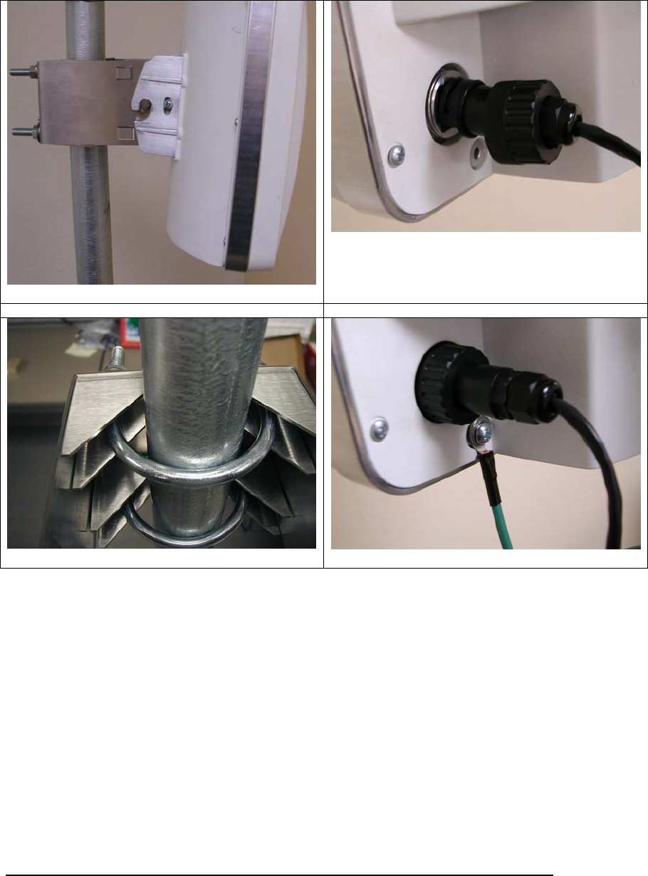
Pictures helpful for installation
ODU with mounting bracket
ODU connection not weather secured
ODU pole mounting bracket (inside view)
ODU connection ready with ground wire
TSUNAMI MULTIPOINT
3-6
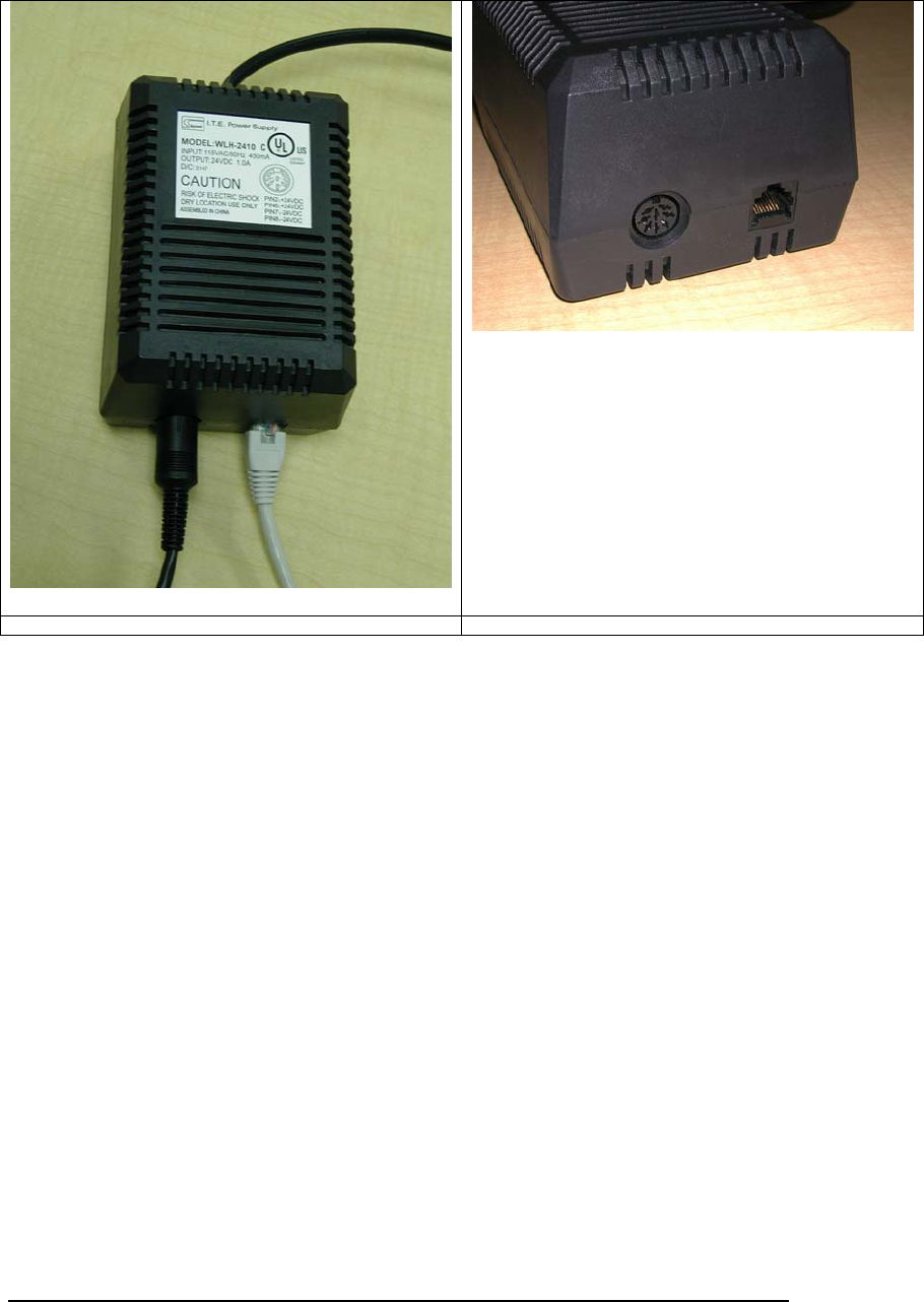
Power Brick Adapter with DIN and Ethernet
Power Brick Adapter cable connection detail
TSUNAMI MULTIPOINT
3-7
Software Installation
Use the enclosed CD and install per instructions found on the CD in the ‘readme.txt’
file.
Subscriber Unit Configuration
CONNECT ALL CABLES BEFORE PLUGGING INTO AC POWER
DISCONNECT AC POWER FIRST BEFORE REMOVING THE CABLE BETWEEN
THE POWER SUPPLY AND THE OUTSIDE UNIT (ODU).
ONLY THEN APPLY AC POWER
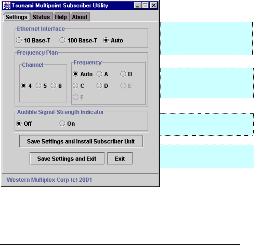
The README text file provides detailed instructions on how to launch the
installation program. After flowing the directions, click on the “Settings” tab for the
following set-up screen to appear:
Note: Any “Settings” are only saved if either “Save Settings …” button is selected.
If the BSU frequency is known,
setting to that value (instead of Auto)
will reduce the chance of acquiring
an undesired BSU.
The Ethernet Interface may be
configured to use 10Base-T,
100Base-T, or auto-negotiated
10/100Base-T (recommended).
Select “Off” if the “beeper” is not
desired to indicate signal-strength.
Select “Save Settings and Install…” to
start the wireless network connection.
TSUNAMI MULTIPOINT
3-8
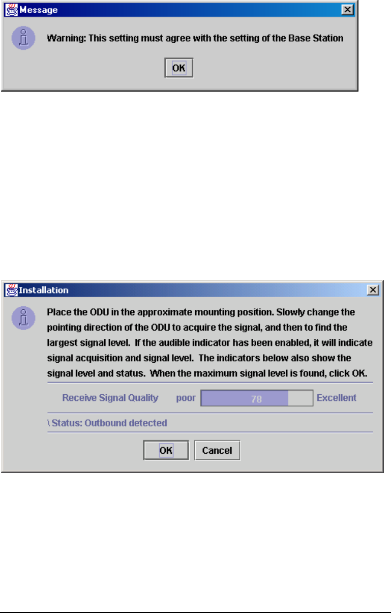
If the Frequency Plan is set to a fixed channel setting, it must be the same as the Base
Station and the following warning will be displayed.
Press OK to continue. After selecting “Save Settings and Install Subscriber Unit”, the
following screen appears and the SU searches for an outbound signal from a Base
Station. Point the SU in the direction of the BSU. Immediately after detecting a
signal, a short tone will be heard, followed by a series of “beeps” indicating the
strength of the BSU’s signal. If a BSU signal is not detected, slowly move the
pointing direction of the SU until the detection tone is heard. Then carefully center
(slowly move ODU both left & right) to the fastest repeating sound (beeps are almost
continuous). This would be the optimum setting for the SU’s ODU antenna. At the
PC where the software was loaded, the following screen also provides a relative
indication of the strength of the received signal which will coincide with the beeping
being more rapid the more the “Receive Signal Quality” meter moves it bar to the
right (Excellent).
Note: If the time to align the SU takes more than 15 minutes, the audible
sound will stop and the SU will attempt to connect with the BSU. If more than
15 minutes is required, disconnect and reconnect the power at the indoor
power supply (brick) to reset the 15-minute timer and re-start the above
process.
TSUNAMI MULTIPOINT
3-9
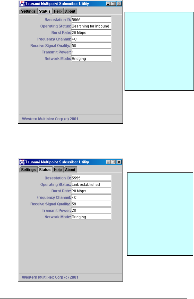
After maximizing the signal strength, click “OK” to continue the process of
establishing the wireless connection. The “Status” screen is displayed and the progress
of the connection with the BSU is shown in the Operating Status line. Other
communication link details are also shown.
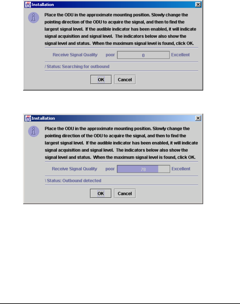
The following are the typical series that would be encountered during the set-up and
antenna alignment stages:
1) “ODU not connected” until the SU cable is connected and power is applied.
2) “Searching for outbound” – point the SU to find a signal.
3) “Outbound detected” – point the SU to maximize the signal strength.
TSUNAMI MULTIPOINT
3-10
4) “Searching for inbound”
5) “Inbound acquired” - this may show only for a short moment.
6) “Link established” -congratulations – the link is ready!
N
ote:
If “Searching for outbound” and
“Outbound detected” are alternately
viewed, and the status never gets to
the “Searching for inbound” step, the
BSU is not acquirable with enough
signal level from the Subscriber
Unit.
If the message “Network control
message not received,” this could be
for the same reason as stated above.
N
ote:
Either the Installation screens on the
p
revious page or the Utility screen to
the left will continuously indicate the
operating status of the communication
situation.
It is suggested that the Status screen be
used until the signal is peaked before
selecting the Status screen. While in
the connection process, the line to the
left of “status” rotates to indicate
continuous process action.

TSUNAMI MULTIPOINT
3-11
To determine connection with host and/or Internet
Use the ARP command in a DOS window: type “arp –a” (without the quotes) and
receive a response with IP address and MAC address, you are connected. In addition
you can use the PING command if you where given an IP address of a router or PC
to query. If you expect an Internet connection, you may start your favorite browser
and attempt to get to a particular web site.
HELP:
Status screen providing operational status of your wireless connection.
The following are the descriptions details for the above screen:
Basestation ID: The ID of the particular Base Station you are communicating
with.
Burst Rate: The one-way data transfer speed of the BSU<->SU
communication link.
Frequency Channel: The particular channel used for communication with the Base
Station
Receive Signal Quality: The quality of the communication connection at this moment
(0-100) – a signal over 40 is acceptable.
Transmit Power: The level of transmitter power being used at this moment (-
30 to +36).
Network Mode: The operational mode being used by the Base Station
(Bridging, VPN or IP Routing)

TSUNAMI MULTIPOINT
3-12
The “About” page provides the current software revision levels
Click on the “Help” tab to use this online manual.
DESIGN CUSTOMIZATION
4-1
4 SU Connections
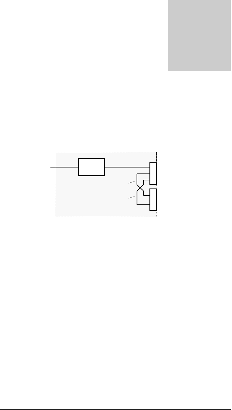
SU Power Adapter (Power Brick)
The Power Adapter is an indoor unit that supplies power and a 10/100Base-T
Ethernet connection to the ODU though the Interface Cable, as shown.
Figure 4-1: Diagram of Power Adapter/Brick
SU Installation Kit
The SU Installation Kit provides necessary instructions, cabling, mounting hardware,
and software to install the SU at the customer’s premises; and includes the following
items:
Installation and Operating Instructions.
ODU interface cable, 25 meters long with connectors. Optional lengths of 50 and 75
meters can also be made available.
Mounting hardware.
Installation software on CD-ROM.
Chapter
4
AC/DC
Converter
J1
I
nterface Cable to ODU
J2
10/100Base-T Ethernet Port
P
1
120 VAC input power
28 VDC
Tx UTP
Rx UTP
Power Adapter
TSUNAMI MULTIPOINT
4-2
Interfaces
Broadband Air Interface
The SU ODU complies with the physical and data link layers of the downlink and
uplink RF signals.
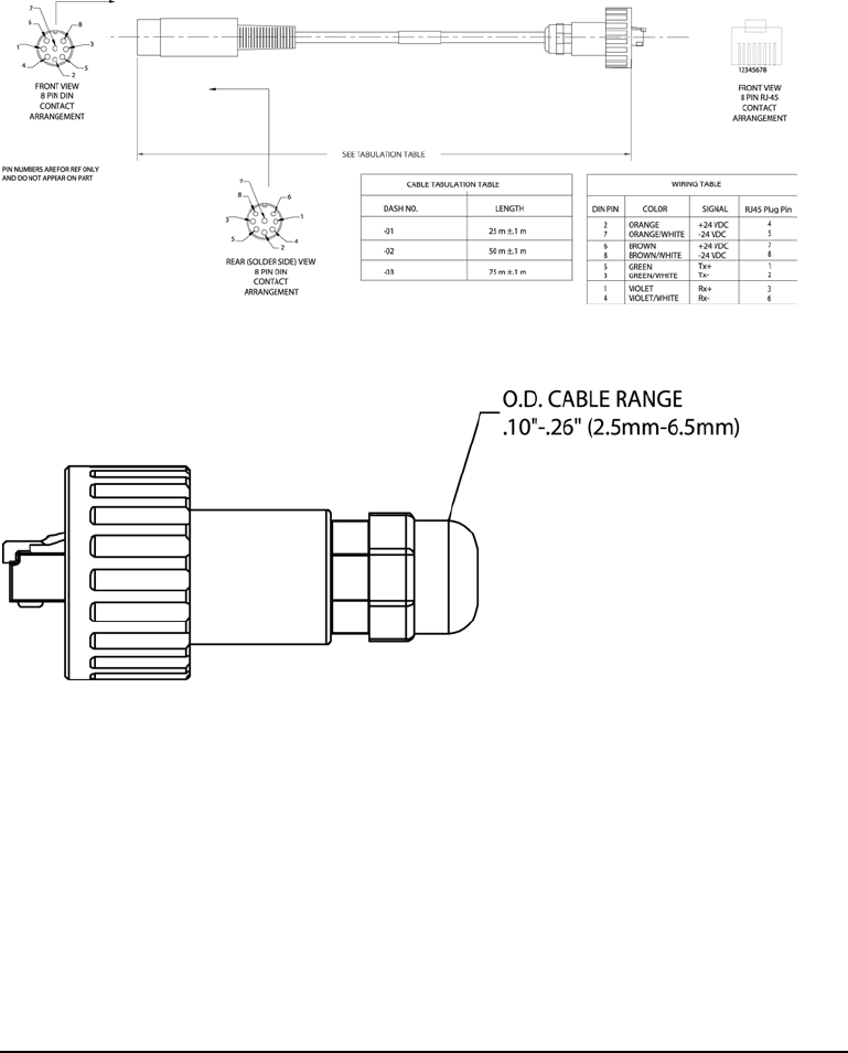
ODU (J1) to Power Adapter Interface (J1)
The ODU J1 is an RJ-45 receptacle and the Power Adapter J1 connector is an 8-pin
DIN female receptacle. The functional and electrical interface is specified in Table 4-1
and Figures 4-2, 4-3, 4-4 and 4-5.
Figure 4-3: Subscriber Unit Cable Detail
Figure 4-4: ODU Interface (J1)
If necessary to install or replace this connector, first put over the raw cable the plastic
parts in the order seen above. Then crimp on the properly prepared CAT5 (or better)
cable the RJ45 connector per the pin-out in Table 4-1. Then slide the plastic housing
over the RJ45 connector being sure to align the RJ45 clip into the proper side. Tighten
down the back of the connector for weather sealing and so the cable does not slip.
Finally, install the O-ring between the RJ45 connector and the knurled knob which
will be screwed tightly onto the connector on the back of the ODU after the RJ45
connector is properly seated.
TSUNAMI MULTIPOINT
4-3
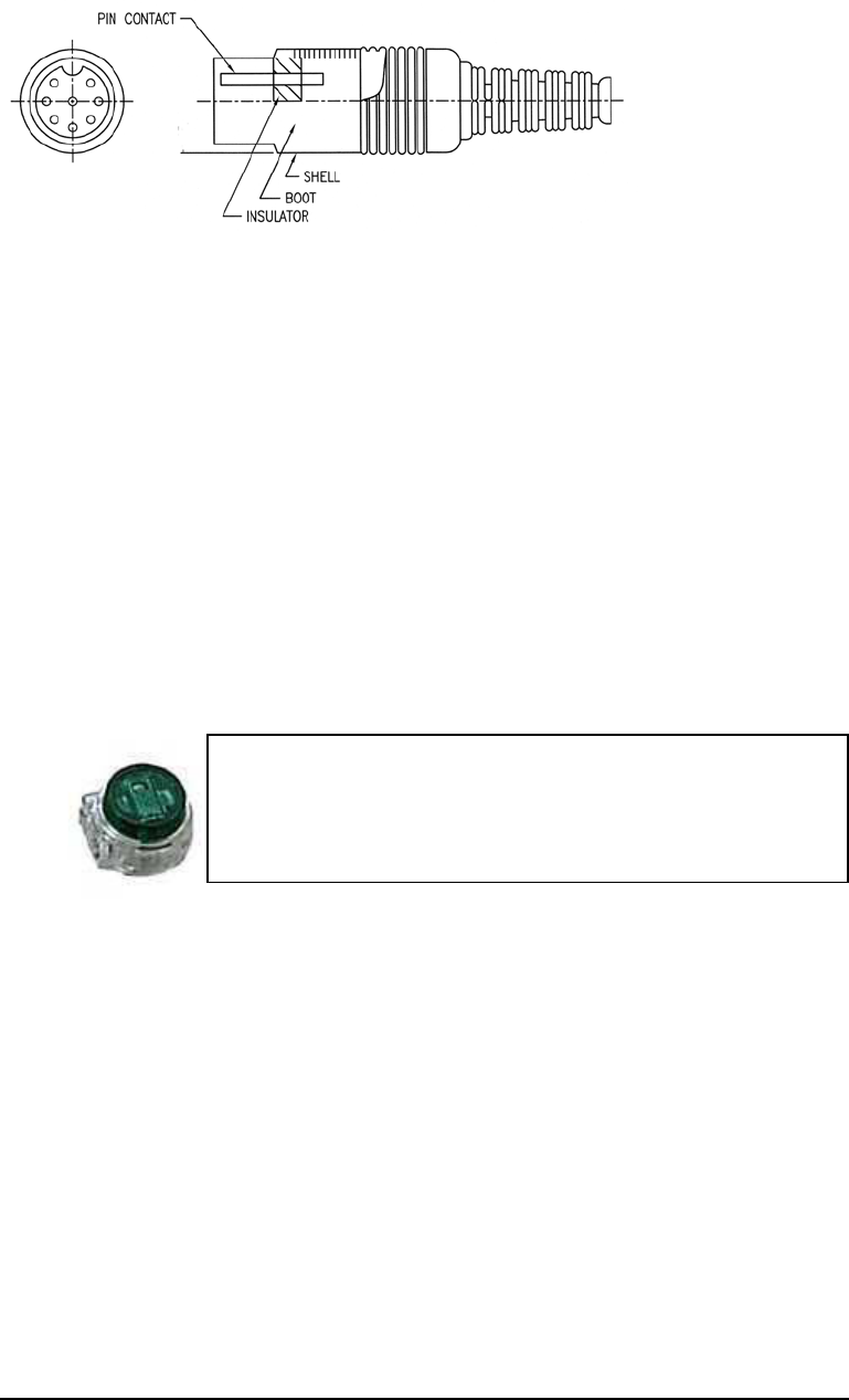
Figure 4-5: Power Adapter Interface (J1)
If necessary to install or replace the above DIN connector, first put over the raw cable
the plastic parts in the order seen above and crimp the pins on the properly prepared
wire ends. Then slide the plastic housing over the metal part of the DIN connector
being sure to align it. This connector is then ready to plug into the Power Brick inside.
Alternative Method of Connection
Another method that is acceptable is to use what are called “jelly beans” or Telephone
Wire Tap Connectors. These moisture resistant and easy to install devices have been
used by the telephone industry for years both indoors and out (for this installation,
recommendation is for using only indoors). These can be purchased at many
electronic supply stores worldwide including Radio Shack (part #64-3081), Tandy or
through most well stocked DYI stores. For this method, you will need eight (8) of
these devices per cable.
Where you had to cut the cable for entry or egress, strip back the outer CAT5 cable
jacket about two (2) inches on each side of the cut – do not strip the individual wires
leaving bare copper! Into each 2-wire Tap Connector, push in the like colored wires
from each cable end firmly and equally into the Tap. While holding the wires in firmly,
squeeze the button with wide pliers to equally force the button into the Tap. If
properly done, the button will now be flush with the rest of the Tap Connector body
and the two wires will not pull out. Continue with the installation of seven (7) more of
these Taps being sure that each wire from the ends of each severed cables match
exactly in color per each Telephone-type Wire Tap Connector.
Refer to the table below that provides the details on each of the eight (8) wires that will
need to be spliced from one cable to the like color on the other cable. After
successfully installing the wire tap devices, the severed cable will carry the Ethernet
and voltages necessary for operation.
Self-stripping tap connectors permit a continuous feed or
loop without interruptions and let you splice wires
without cutting any conductors. The connectors can be
used with 19-26 gauge wire and resist moisture.

TSUNAMI MULTIPOINT
4-4
Table 4-1: ODU to Power Adapter Interface Cable Definition.
Signal Power Adapter J1
pin (DIN)
ODU
J1 pin (RJ45)
Signal Definition
DC28V_+ 2, 6 4, 7 28VDC power return
DC28V_- 7, 8 5, 8 28VDC power: ODU accepts 18 VDC to
30 VDC at 1 ampere maximum
SU_Tx_D+ 5 1 Positive transmit data from SU conforming
to IEEE 802.3 10/100Base-T
SU_Tx_D- 3 2 Negative transmit data from SU
conforming to IEEE 802.3 10/100Base-T
SU_Rx_D+ 1 3 Positive receive data to SU conforming to
IEEE 802.3 10/100Base-T
SU_Rx_D- 4 6 Negative receive data to SU conforming
to IEEE 802.3 10/100Base-T
Figure 4-6: Power Adapter and ODU Connectors
Power Adapter Ethernet Port (J2)
The Ethernet Port J2 connector is an RJ-45 receptacle. The functional and
electrical interface is specified in Table 4-2.
Table 4-2: Ethernet Port Interface Definition.
Signal Power Adapter J2
pin
Signal Definition
SU_Tx_D+ 3 Positive transmit data from SU conforming to
IEEE 802.3 10Base-T
(connects to customer_Rx_D+)
SU_Tx_D- 6 Negative transmit data from SU conforming to
IEEE 802.3 10Base-T
(connects to customer_Rx_D-)
SU_Rx_D+ 1 Positive receive data to SU conforming to IEEE
802.3 10Base-T
(connects to customer_Tx_D+)
SU_Rx_D- 2 Negative receive data to SU conforming to
IEEE 802.3 10Base-T
(connects to customer_Tx_D-)
4, 5, 7, 8 Not connected
AC Power Input (P1)
The Power Adapter accepts an AC input alternating current at 47 to 63 Hz. The
Power Adapter draws less than 450 milliamperes with an input voltage of 120 volts.
Power Adapter DIN ODU RJ-45

TSUNAMI MULTIPOINT
4-5
ETHERNET INTERFACE
The RJ45 Ethernet communications are compatible with ANSI/IEEE 802.3u, type
Ethernet-II 10/100Base-T, and IPv4. The SU ODU hardware contains a unique
MAC ID that is used for its Ethernet address.
NETWORK MODES
The SU supports the following three network operating modes: IP routing,
Ethernet bridging, and Ethernet bridging with VLAN tagging. These modes are
defined below. The Base Station controls the network mode, and the SU follows.
Network Mode Description
IP Routing The SU asserts itself as the network gateway, and
accepts for transmission all IP packets that are not meant
for the local network. Similarly, the SU filters the
downlink packets and selects only IP packets with
destinations that are known to be local. Local IP
addresses are either statically programmed into the SU,
or are learned by gleaning DHCP messages and
upstream traffic.
Ethernet Bridging The SU accepts for uplink transmission all Ethernet
packets with destination addresses that are not on the
local network as learned from observing the source
addresses. Similarly, the SU filters the downlink packets
and selects only packets with local Ethernet destinations
that have been learned by observing local source
addresses.
Ethernet Bridging with
VLAN Tagging
The SU operates similar to the Ethernet bridging mode,
but tags uplink packets with a VLAN ID provided by the
BSU. The SU removes VLAN tags from downlink
Ethernet packets that are selected for output.
NETWORK CONFIGURATIONS
The SU is compatible with the network configurations shown in Figure 4-6. An
external hub or switch is required to provide Ethernet communications to more than
one host device; a host may be a computer, VoIP terminal, or other terminal that has
an IP and Ethernet MAC address. Each host device must be on the same subnet
when the IP-routing mode is used. A server, or router, implementing Network
Address Translation (NAT) protocols allows a single IP address of the wireless
network to be used to connect multiple devices. When Ethernet bridging mode
without VLAN-tagging enabled is used, a VLAN switch can be connected to separate
several VLANs through a single SU. When VLAN-tagging is enabled, a VLAN switch
is not necessary and a conventional hub or server can be used; however, the SU will
filter tags for only a single VLAN.
SU
PA
Host
SU
PA
Hub
SU
PA
VLAN
Switch
SU
PA
Router/
Server

TSUNAMI MULTIPOINT
4-6
Figure 4-7: Representative Networking Configurations

DESIGN CUSTOMIZATION
5-1
5 TROUBLESHOOTING
Regular Maintenance
There is no regular maintenance required except to keep the surfaces free from debris,
dirt and dust.
Problem – Solution Section
Problem:
“ODU not connected” is displayed.
Possible Causes:
Cable from power brick to ODU not connected
Power brick not turned on
Cable from power brick to PC is not connected, or is a cross-over cable
(should be straight)
Recommended Actions:
Recheck cable connections and wiring for cuts, etc. If possible, use another
cable assembly and re-try. Use a straight if crossed, and vice versa for the cable
between the power brick and your PC or LAN.
Problem:
“Outbound detection” does not occur, or “Searching outbound” is displayed
permanently.
Chapter
5

TSUNAMI MULTIPOINT
5-2
Possible Causes:
Improper radio settings (e.g. frequency plan or channel)
Signal blockage, severe path fading, or antenna misalignment
Interference (other 5.3/5.8 GHz transmitters nearby)
Recommended Actions:
Recheck subscriber unit set-up, etc. Redo the antenna alignment and be sure
to swing the antenna left and right significantly to be sure you are acquiring
the best signal level (go from no signal in each direction and center between
these two positions). May need to mount the ODU in a different location if
the signal is marginal (below 50) or is fluctuating (not a steady value). Check to
be sure the antenna is pointed to the intended BSU for the area.
Problem:
Status alternates between “Searching outbound” and “Outbound detection”.
Possible Causes:
Burst rate of the outbound signal exceeds the burst rate limit of the SU
Recommended Actions:
Upgrade to a faster model
See if there is another BSU available with a compatible burst rate
Problem:
“Inbound detection” does not occur
Possible Causes:
Interference at the BSU

TSUNAMI MULTIPOINT
5-3
Recommended Actions:
If accompanied by weak Receiver Signal Quality, the path loss may be
excessive due to foliage blockage, severe fading, or antenna misalignment.
Problem:
“Inbound acquired” displayed, but “Link established “ does not occur
Possible Causes:
BSU does not have the SU’s Ethernet Address in it’s authentication table
The SU has been moved and the BSU range security feature is enabled.
Recommended Actions:
BSU operator must add the SU Ethernet Address
The BSU operator must reset the range-security lockout for the SU settings
(e.g. frequency plan or channel)

TSUNAMI MULTIPOINT
5-4
Repair and Return Instructions and
Policy Statement
Should it become necessary to send a product(s) in for repair,
please call 408-542-5390 ext. 2 (technical support) or you may email your request to
support@wmux.com, Monday through Friday 8:00 am – 5:00 pm PST, excluding U.S.
holidays.
Below is a list of information needed prior to the issue of an RMA#:
• A service order number, assigned by a Western Multiplex technical support
engineer.
• Model and serial # of each unit.
• A validated failure description of each unit. Our technical assistance
personnel can assist in failure validation.
• Company name, billing, and shipping address.
• Contact person name and phone #.
• A purchase order # if the unit is out of warranty.
• A hardcopy of the PO# is required for any repair cost greater than
$1,000.00. Please fax to 408-542-3375 prior to the return of the unit.
For other warranty details please refer to the warranty page in the first section of the manual.
Policies associated with the return of product:
• RMA numbers are assigned within 24 hours of request or 24 hours after all
information is made available to WMUX.
• WMUX makes every effort to ensure a 30 day turnaround time from receipt of
product to the shipment of product back to the customer.
• Proper and adequate packaging must be used for shipments. When available the
original packing boxes should be used.
• The RMA number must reside on the outside of the box and referenced on
shipping paperwork. Product delivered without proper identification will either be
shipped back to originator or delivered to a discrepancy area until proper
identification can be made. This will cause delay in receipt of product into
WMUX.
• No more than 10 products can be returned at any one time.
Other available services:
• Expediting fees and advanced exchange options are available at per incident
rates and are subject to inventory. Options and quotes can be given to you at
the time of request.

5-5
INDEX
A
About..................................................................... 3-12
Antenna ................................................................... 2-8
Antennas .................................................................2-5
ARP command ......................................................3-11
B
Burst rate........................................................2-7, 3-11
C
Cable ........................................................ 2-4, 2-8, 4-3
CD ........................................................................... 3-7
Configuration .......................................................... 3-7
Connectors ..............................................................4-4
Considerations ........................................................ 2-2
D
Distance ...........................................................2-7
E
Electrical ................................................................. 2-8
Environmental......................................................... 2-8
F
FCC ......................................................................... 2-6
Frequency................................................................ 2-8
H
Help....................................................................... 3-11
I
Installation............................................................... 2-2
Installation kit ......................................................... 4-1
Interference ............................................................. 2-4
L
Lightning................................................................. 2-3
Lightning protection ...............................................2-4
Location ..................................................................3-4
M
Maintenance ........................................................... 5-1
Mounting ......................................................... 2-9, 3-3
N
Network mode ...................................................... 3-11
P
Path planning.......................................................... 2-6
Pictures ................................................................... 3-5
PING command .................................................... 3-11
Polarization............................................................. 2-5
Power adapter .................................................. 4-1, 4-2
Problem – solution ................................................. 5-1
R
Rain......................................................................... 2-3
Repair and return .................................................... 5-4
S
Safety instructions .................................................. 1-4
Security................................................................... 2-8
Set-up...................................................................... 3-1
T
Tower...................................................................... 2-6
Troubleshooting...................................................... 5-1
U
Unlicensed .............................................................. 2-6
Unpacking............................................................... 3-1
Upgrades................................................................. 2-8
V
VLAN ..................................................................... 4-5
W
Weather................................................................... 2-3
Wind ....................................................................... 2-3