550834 3 Goulds 6 10 Three Phase Motors Installation Data Manual
551226 2 Goulds (100-275H) 6 Inch And Larger High Capacity Pump End Installation Data Manual 551226_2_Goulds (100-275H) 6 Inch And Larger High Capacity Pump End Installation Data Manual
551229 2 Goulds (100-275H) 6 Inch And Larger High Capacity Pump End Installation Data Manual 551229_2_Goulds (100-275H) 6 Inch And Larger High Capacity Pump End Installation Data Manual
550748 3 Goulds Centrpro 6 Inch Motors Three Phase Installation Data Manual 550748_3_Goulds CentrPro 6 Inch Motors Three Phase Installation Data Manual
551225 1 Goulds (100-275H) 6 Inch And Larger High Capactiy Pump End Instruction Data Manual 551225_1_Goulds (100-275H) 6 Inch And Larger HIgh Capactiy Pump End Instruction Data Manual
550801 1 Goulds (100-275H) 6 Inch And Larger High Capactiy Pump End Instruction Data Manual 550801_1_Goulds (100-275H) 6 Inch And Larger HIgh Capactiy Pump End Instruction Data Manual
: Pump 550834 3 Goulds 6-10 Three Phase Motors Installation Data Manual 550834_3_Goulds 6-10 Three Phase Motors Installation Data Manual pdf
Open the PDF directly: View PDF ![]() .
.
Page Count: 60
BMAID R9
Motor Application and
Installation Data

PAGE 2
Residential Water Systems
CentriPro
INDEX
GENERAL INFORMATION
Storage, Frequency of Starts, Temperature Ratings, Flow Sleeve .............................................................................. 3-4
CENTRIPRO 4" SUBMERSIBLE MOTOR DATA
Motor and Control Box Cross Reference Data .................................................................................................................5
Single-phase 2-wire Data ..........................................................................................................................................6-7, 10
Single-phase 3-wire Data ............................................................................................................................................ 11-13
4" Motor Wire Sizing Charts and Using Two Cable Sizes ...................................................................................... 14, 17
Three Phase 4" Motor Data ....................................................................................................................................... 15, 16
CENTRIPRO 6" - 10" MOTOR DATA
Single-phase 6" Motors ..............................................................................................................................................18-19
Three-phase 6" - 10" Motors ......................................................................................................................................18-19
Single Phase 6” Motor Control Box Data ....................................................................................................................... 20
75º C Wire Charts For 6-10" CentriPro Motors .............................................................................................................. 21
FM-Series 6" Submersible Motors .............................................................................................................................22-23
Single Phase 6” FM-Series Motor Control Box Data..................................................................................................... 24
75º C Wire Charts For FM-Series 6-10" CentriPro Motors ........................................................................................... 25
1Ø CONTROL BOXES, 3Ø STARTERS, BALANCED FLOW CONTROLLER
Quick Disconnect 1Ø Control Box - Data, Parts and Wiring ....................................................................................... 26
Installing a Symcom Insider (Or Pumptec™) in a Control Box ............................................................................... 27-28
MC and CSCR 1Ø Control Box - Data, Parts, Check-Out and Wiring .................................................................... 29-33
Pump Troubleshooting ..................................................................................................................................................... 34
Aquavar SOLO2 Data ........................................................................................................................................................ 35
Aquavar SOLO2 and Balanced Flow Repair Parts ......................................................................................................... 36
Three Phase Motor Operation on VFD’s ........................................................................................................................ 37
Aquavar SOLO2 (Balanced Flow) Data Troubleshooting ........................................................................................38-42
ELECTRICAL AND GENERAL INFORMATION
Electrical Tests ..............................................................................................................................................................43-47
Transformer Sizing ............................................................................................................................................................ 48
Three Phase Unbalance ................................................................................................................................................... 49
Generator Sizing Chart..................................................................................................................................................... 50
Cost of Operation, Head and Pressure Equivalents ..................................................................................................... 51
Pressure Switches ............................................................................................................................................................. 52
Common Terms and Formulas ........................................................................................................................................ 53
Tank Selection ................................................................................................................................................................... 54
Jet Pump Motor Data and Electrical Components ....................................................................................................... 55
Jet Pump Motor Wiring A.O. Smith Motors ................................................................................................................... 56
Friction Loss ....................................................................................................................................................................... 57
Agency Listings and Logos .........................................................................................................................................58-59
ADDITIONAL TECHNICAL DATA IN THIS MANUAL
Although this is basically a Motor Manual our experience has proven that proper troubleshooting and motor installation
also requires well and pump information. To that end we have added non-typical technical data to this manual to assist
you in making informed, thorough troubleshooting and installation decisions. We hope you nd these additions helpful.
PAGE 3
Residential Water Systems
CentriPro
MOTOR STORAGE
Water lubricated 4" motors are lled with a non-toxic, Propylene Glycol and water solution to prevent damage
from freezing temperatures. We recommend storing 4” motors where temperatures are above 0º F. If stored
in colder temperatures (down to -40º F) the ll solution will become slushy, in this case the motor should be
allowed to sit in the well for several minutes before operating. If stored in an area where temperatures range
from freezing to over 100º F some ll solution may be expelled from the motor. If the leakage appears signicant
we suggest installing (submerging) the motor for 10 minutes before starting to allow the check valve to do its job
and replace the lost uid.
Six inch and larger motors are protected from freezing to -22º F (-30º C). Checking instructions are in the 6" and
Larger Pump IOM.
When removing a used motor from a well it must be protected from freezing as it may have taken on well water
and no longer have enough propylene glycol in solution to prevent freezing.
Coolant Leakage — during storage or shipment, it is common for some coolant/uid to leak from the motors,
this should not be a concern. The ltered check valve will rell the motor upon submergence in a well. If leakage
appears extraordinary or you are concerned, please call the nearest factory customer service number found on
the back cover of this manual for checking instructions.
FREQUENCY OF STARTS
A one (1) minute minimum run cycle for pumps and motors up to 1.5 HP and two (2) minutes for 2 HP and larger
motors is recommended. Six inch and larger motors should have a minimum of 15 minutes between starts or
starting attempts to allow cooling. Motor, pressure switch, tank and pump life may be extended by limiting starts
per hour and per day. Proper tank sizing is critical to control pump cycle times. Excessive or rapid cycling creates
heat which can prematurely damage motors, switches and controls.
Motor Starting Frequency
HP Single-Phase Three-Phase
Starts / 24hr Starts / 24hr
1/2 thru 3/4 300 300
1 thru 5 100 300
7.5 thru 30 50 100
40 and over - 100
MOTOR INSTALLATION POSITION
Best service life is obtained when motors are installed in a vertical position. Installing in a horizontal position is
allowable. It is best if the shaft end is at least 15º higher than the bottom of the motor. This places some weight
on the thrust bearing which helps to prevent thrust bearing coast down wear as the motor slows down. When
installed in horizontal installations we recommend keeping starts to a minimum and maintaining back pressure
(head) on the system. Even when installed vertically, operating pumps at Open Discharge with little or no Head
(to the far right of the pump curve) may create excessive upward thrust which may damage the motor’s upthrust
bearing and internal pump parts – in applications with high static water levels or little system head always use a
throttling valve in the discharge line to create back pressure (head) on the pump and bearing.
CONTROL BOX MOUNTING
Single phase submersible control boxes feature NEMA 3R enclosures for indoor or outdoor mounting. They
should be mounted in a vertical position as relay manufacturers recommend correct relay positioning for proper,
trouble-free operation.
Control boxes should be shaded from direct sunlight in areas where temperatures exceed 90º F as excessive
heat may shorten capacitor life. It is advisable to paint the enclosure white if outside in very hot, sunny climates.
PAGE 4
Residential Water Systems
CentriPro
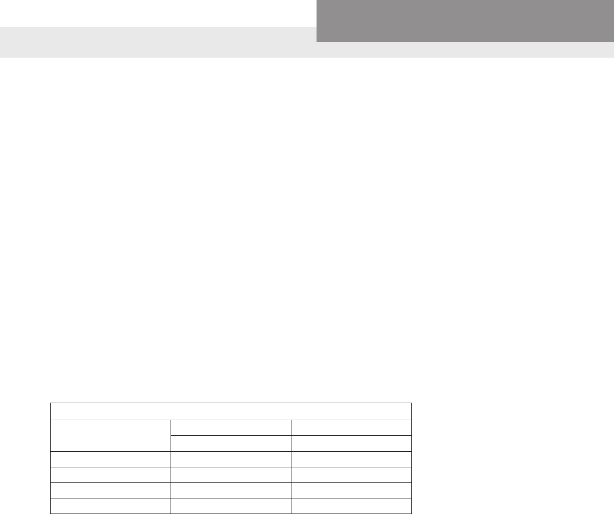
MOTOR COOLING, TEMPERATURE AND TIME RATINGS
All 4 inch CentriPro motors may be operated continuously in water up to 86º F. Optimum
service life will be attained by maintaining a minimum ow rate past the motor of .25 feet
per second. Use a Flow Sleeve if velocity is below the .25’/sec, if the well is top feeding or
when the pump is used in a large body of water or large tank.
Six (6) inch canned design motors from 5 – 40 HP will operate in water up to 95º F (35º C),
without any de-rating of horsepower, with a minimum ow rate of .5 ft./sec. past the motor.
6" – 50 HP and all 8" – 10" motors can operate in 77º F (25º C) water with .5'/sec velocity past
the motor.
One way to make a ow sleeve is to install a well seal above the pump discharge and slip a
piece of casing over the pump and afx it to the well seal. Drill three holes at 120º intervals
on the lower section of the casing and insert (3) screws and nuts through the casing, just
touching the motor. Tighten the nuts out against the casing. Insure that the screws do not
protrude out too far as you don’t want them catching on well joints.
PUMP COOLING AND LUBRICATION
In addition to motor cooling, another reason to maintain minimum ow rates is pump
lubrication. All manufacturers’, either on curves or in selection charts, show minimum ows.
This insures that rotating pump parts are properly lubricated to prolong service life and
reduce friction. A dead headed pump will super heat water very quickly, and hot water has
no lubricity.
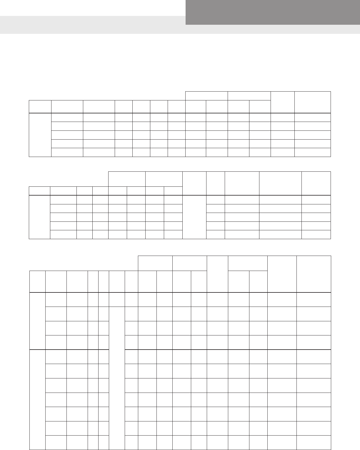
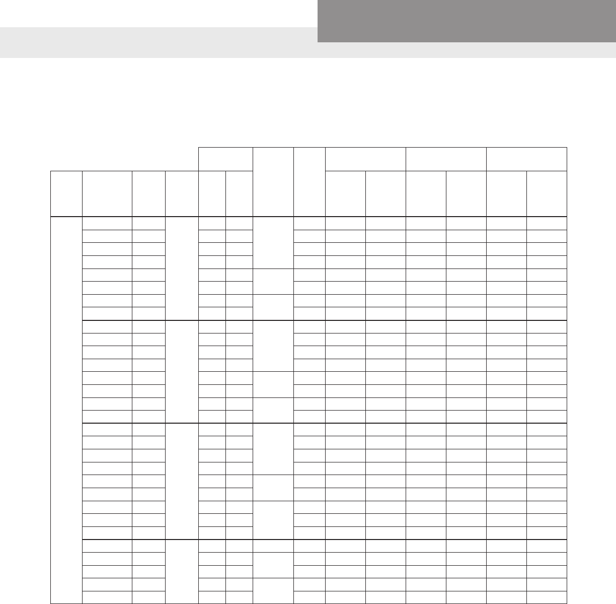
MINIMUM FLOW RATES FOR PROPER MOTOR COOLING
FLOW SLEEVE
Well or Sleeve
Diameter
(inches)
3.75" Diameter
4" CP Motor .25'/sec
CP = 5.5" Dia.
6" CP Motor .5'/sec.
FM = 5.4" Dia.
6" FM Motor .5'/sec.
CP = 7.5" Dia.
8" CP Motor .5'/sec.
GPM Required
4 1.2 – – –
5 7 – – –
6 13 7 9 –
7 20 23 24 –
8 30 41 44 9
10 50 85 88 53
12 80 139 143 107
14 110 198 199 170
16 150 276 277 313
Multiply gpm by .2271 for m3/Hr. Multiply gpm by 3.785 for l/min.
Motor Diameter Well Casing or Flow Sleeve Diameter
4" 6" 8" 10" 12" 14" 16"
4" 25 269 — — — — —
6" — 77 395 830 1328 1679 2303
8" — -- 84 519 1017 1368 1992
RECOMMENDED MAXIMUM FLOW RATE IN GPM
PAGE 5
Residential Water Systems
CentriPro
CROSS REFERENCE
CONTROL BOX CROSS REFERENCE
New Control Box #'s = Old Model Numbers
Control Replaces Replaces Replaces Red Jacket
Box HP Volts CentriPro Brand F. E. Goulds CB RJ CB RJ - FE
Type Control Box
0.5 115 CB05411 2801044915 00043 (G) - 50F301CB
QD 0.5 230 CB05412 2801054902 00044 (G) - 50F311CB
0.75 230 CB07412 2801074915 00054 (G) - 75F311CB
1 230 CB10412 2801084915 00064 (G) - 100F311CB
0.5 230 CB05412CR 2824055015 00044CR S50N1CB -
0.75 230 CB07412CR 2824075015 00054CR S75N1CB -
CSCR 1 230 CB10412CR 2824085015 00064CR S100N1CB -
or 1.5 230 CB15412CR 2823008110 00074 S150N1CB 150F311CB
Integral 2 230 CB20412CR 2823018310 00084 S200N1CB 200F311CB
3 230 CB30412CR 2823028110 00094 S300N1CB 300F311CB
5 230 CB50412CR 2821138110 00104 S500N1CB 500F311CB
1.5 230 CB15412MC
Not Available Before
MC or 2 230 CB20412MC 2823018310 00084MC S200N1CBC 200F311CBC
Deluxe 3 230 CB30412MC 2823028310 00094MC S300N1CBC 300F311CBC
5 230 CB50412MC 2821139310 00104MC S500N1CBC 500F311CBC
New
models
« Left will
replace all
old model
numbers
to the
Right »
MOTOR CROSS REFERENCE
Motor Type HP Volts CentriPro
Order No. Old GWT # Red Jacket
Order No. Old RJ # F.E. #
2-wire
0.5 115 M05421 S04932 50C201 50F201 244504
0.5 230 M05422 S04942 50C211 50F211 244505
0.75 230 M07422 S05942 75C211 75F211 244507
1 230 M10422 S06942 100C211 100F211 244508
1.5 230 M15422 S07942 150C211 150F211 244309
3-wire
0.5 115 M05411 S04930 50C301 50F301 214505
0.5 230 M05412 S04940 50C311 50F311 214505
0.75 230 M07412 S05940 75C311 75F311 214507
1 230 M10412 S06940 100C311 100F311 214508
1.5 230 M15412 S07940 150C311 150F311 224300
2 230 M20412 S08940 200C311 200F311 224301
3 230 M30412 S09940 300C311 300F311 22430226
3 230 N/R S09940HT N/R 300F311HT 22430252
5 230 M50412 S10940 500C311 500F311 224303
PAGE 6
Residential Water Systems
CentriPro
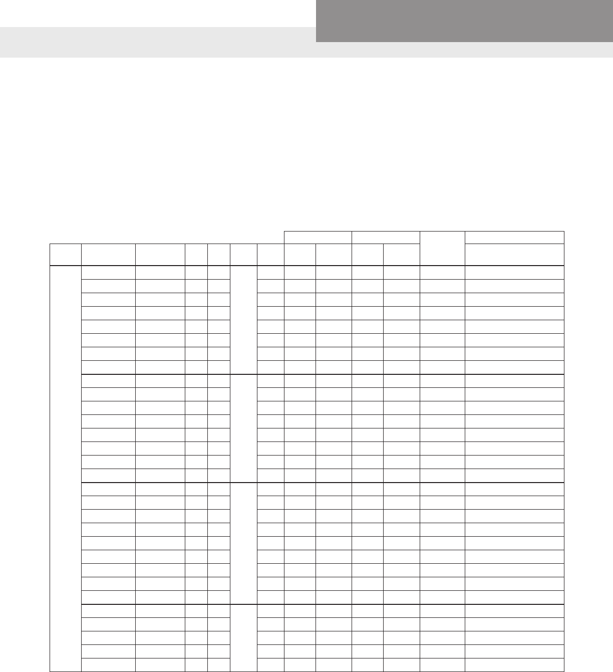
SINGLE PHASE
Generation I Single Phase
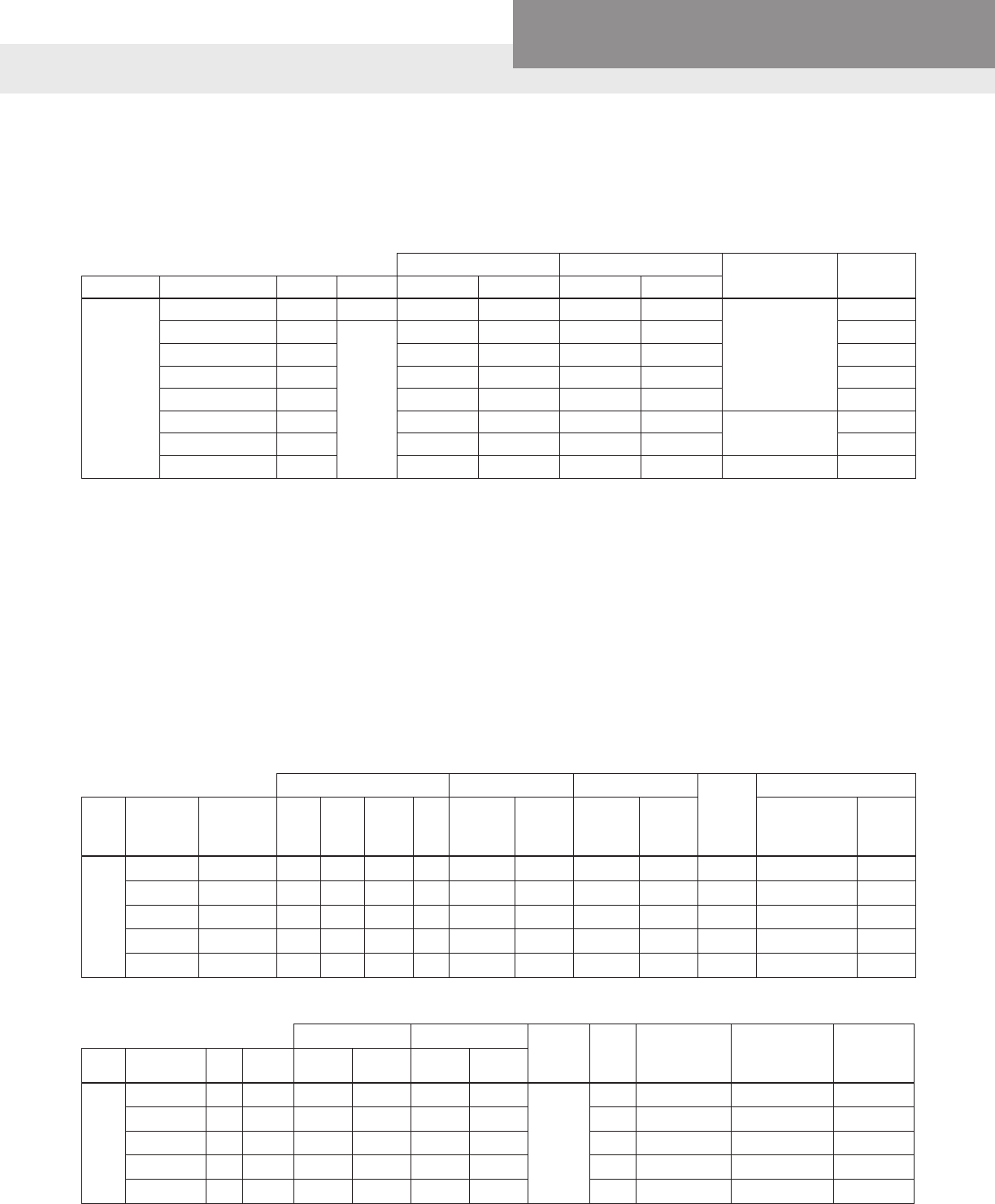
2-WIRE PSC, SINGLE PHASE 4" MOTORS - ELECTRICAL DATA, 60 HZ, 3450 RPM
2-WIRE, SINGLE PHASE 4" MOTORS - ENGINEERING DATA
Efciency % Power Factor
%Thrust
Rating
KVA
Code
Standard
Fuse
Dual
Element Time
Delay Fuse
Circuit
Breaker
Type Model HP Volts F.L. S.F. F.L. S.F.
2-Wire (PSC)
M05421 0.5 115 49 61 99 99
700 #
K 25 15 20
M05422 0.5 230 50 62 97 99 K 15 10 10
M07422 0.75 230 55 65 97 99 J 20 10 15
M10422 1.0 230 58 65 94 96 F 25 15 20
M15422 1.5 230 59 64 99 99 H 30 15 25
Full Load Service Factor Locked
Rotor
Amps
Winding
Resistance
Type Model RJ Ref. # HP KW Volts SF Amps Watts Amps Watts
2-Wire (PSC)
M05421 50C201 0.5 0.37 115 1.6 7.4 845 9.5 1088 36.4 1.3-1.8
M05422 50C211 0.5 0.37 230 1.6 3.7 834 4.7 1073 19.5 4.5-5.2
M07422 75C211 0.75 0.55 230 1.5 5.0 1130 6.4 1459 24.8 3.0-4.8
M10422 100C211 1.0 0.75 230 1.4 7.9 1679 9.1 1990 21.7 4.2-5.2
M15422 150C211 1.5 1.1 230 1.3 9.2 2108 11.0 2520 42.0 1.9-2.3
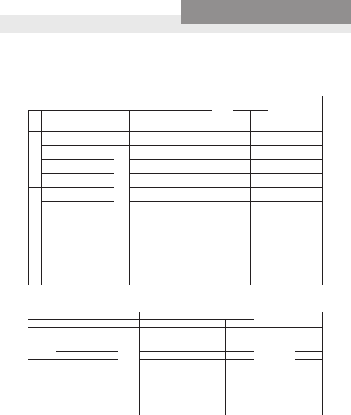
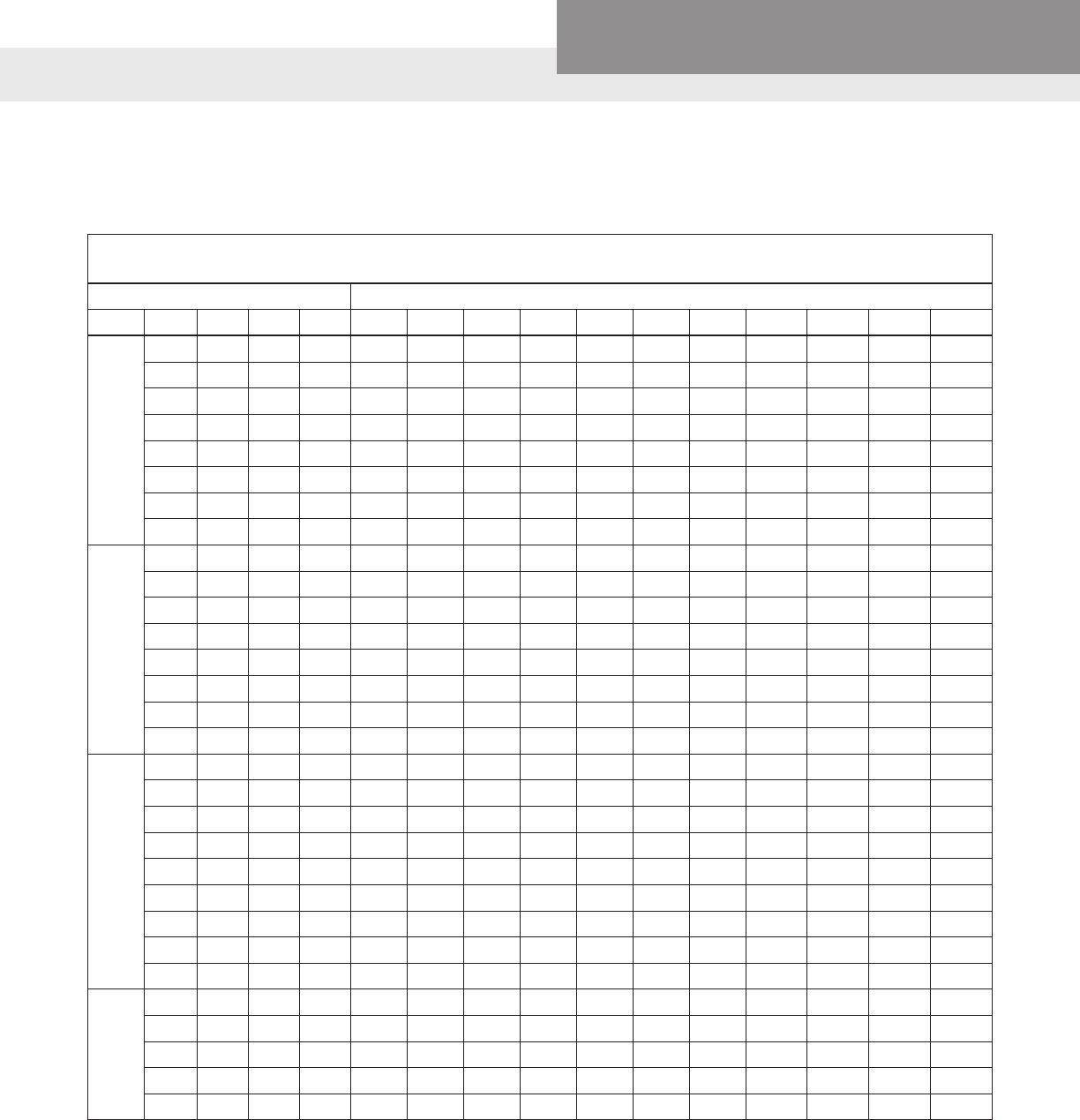
3-WIRE, SINGLE PHASE 4" MOTORS - ELECTRICAL DATA, 60 HZ, 3450 RPM
Full Load Service
Factor Locked
Rotor
Amps
Winding
Resistance Standard
Control
Box
Deluxe
Control Box
(Mag
Contactor)
Type Model RJ Ref.
#HP KW Volts SF Amps Watts Amps Watts
Main
(B-Y or
B-B)
Start
(R-Y)
3-Wire (CSIR)
PREMIUM
M05411 50C301 0.5 0.37 115 1.6 Y – 11.0
B – 11.0
R – 0 733 Y – 12.6
B – 12.6
R – 0 1021 49.6 0.9 - 1.6 5.7 - 7.0 CB05411 -
M05412 50C311 0.5 0.37
230
1.6 Y – 5.5
B – 5.5
R – 0 745 Y – 6.3
B – 6.3
R – 0 1033 22.3 4.2 - 4.9 17.4 -
18.7 CB05412 -
M07412 75C311 0.75 0.55 1.5 Y – 7.2
B – 7.2
R – 0 1014 Y – 8.3
B – 8.3
R – 0 1381 32.0 2.6 - 3.6 11.8 -
13.0 CB07412 -
M10412 100C311 1.0 0.75 1.4 Y – 8.4
B – 8.4
R – 0 1267 Y – 9.7
B – 9.7
R – 0 1672 41.2 2.2 - 3.2 11.3 -
12.3 CB10412 -
3-Wire (CSCR) PREMIUM
M05412 50C311 0.5 0.37 1.6 Y – 4.1
B – 4.1
R – 2.2 720 Y – 4.9
B – 4.4
R – 2.1 955 22.3 4.2 - 4.9 17.4 -
18.7 CB05412CR -
M07412 75C311 0.75 0.55 1.5 Y – 5.1
B – 5.0
R – 3.2 1000 Y – 6.3
B – 5.6
R – 3.1 1300 32.0 2.6 - 3.6 11.8 -
13.0 CB07412CR -
M10412 100C311 1.0 0.75 1.4 Y – 6.1
B – 5.7
R – 3.3 1205 Y – 7.2
B – 6.3
R – 3.3 1530 41.2 2.2 - 3.2 11.3 -
12.3 CB10412CR -
M15412 150C311 1.5 1.1 1.3 Y – 9.7
B – 9.5
R – 1.4 1693 Y – 11.1
B – 11.0
R – 1.3 2187 47.8 1.6 - 2.3 7.9 - 8.7 CB15412CR CB15412MC
M20412 200C311 2.0 1.5 1.25 Y – 9.9
B – 9.1
R – 2.6 2170 Y – 12.2
B – 11.7
R – 2.6 2660 49.4 1.6 - 2.2 10.8 -
12.0 CB20412CR CB20412MC
M30412 300C311 3.0 2.2 1.15 Y – 14.3
B – 12.0
R – 5.7 3170 Y – 16.5
B – 13.9
R – 5.6 3620 76.4 1.1 - 1.4 2.0 - 2.5 CB30412CR CB30412MC
M50412 500C311 5.0 3.7 1.15 Y – 24.0
B – 19.1
R – 10.2 5300 Y – 27.0
B – 22.0
R – 10.0 6030 101.0 0.62 -
0.76
1.36 -
1.66 CB50412CR CB50412MC
PAGE 7
Residential Water Systems
CentriPro
SINGLE PHASE
Generation I Single Phase
Generation II Single Phase (Released April 2011)
2-WIRE MOTORS Identied by a - 01 Nameplate Order No. Sufx
As part of Faradyne Motors' continual improvement process, 3-Wire Generation II motors were introduced in April 2011.
Pump model numbers and motor order numbers remained unchanged. The Motor Nameplate will have a new Faradyne part
number and the Goulds part number on the Motor Nameplate will have a - 01 sufx, example M05422 will be M05422 - 01,
only on the Motor Nameplate not in our catalog or price book.
The self-stick, Mylar motor data stickers we pack with 2 wire motors and complete pumps will be updated with the new
electrical data so that installers will know which motor is installed in the well should service work ever be necessary. Note that
the motor data is only needed to troubleshoot a motor in the well, i.e. resistance and amperage ratings or when installing a
variable speed drive system to set the overloads.
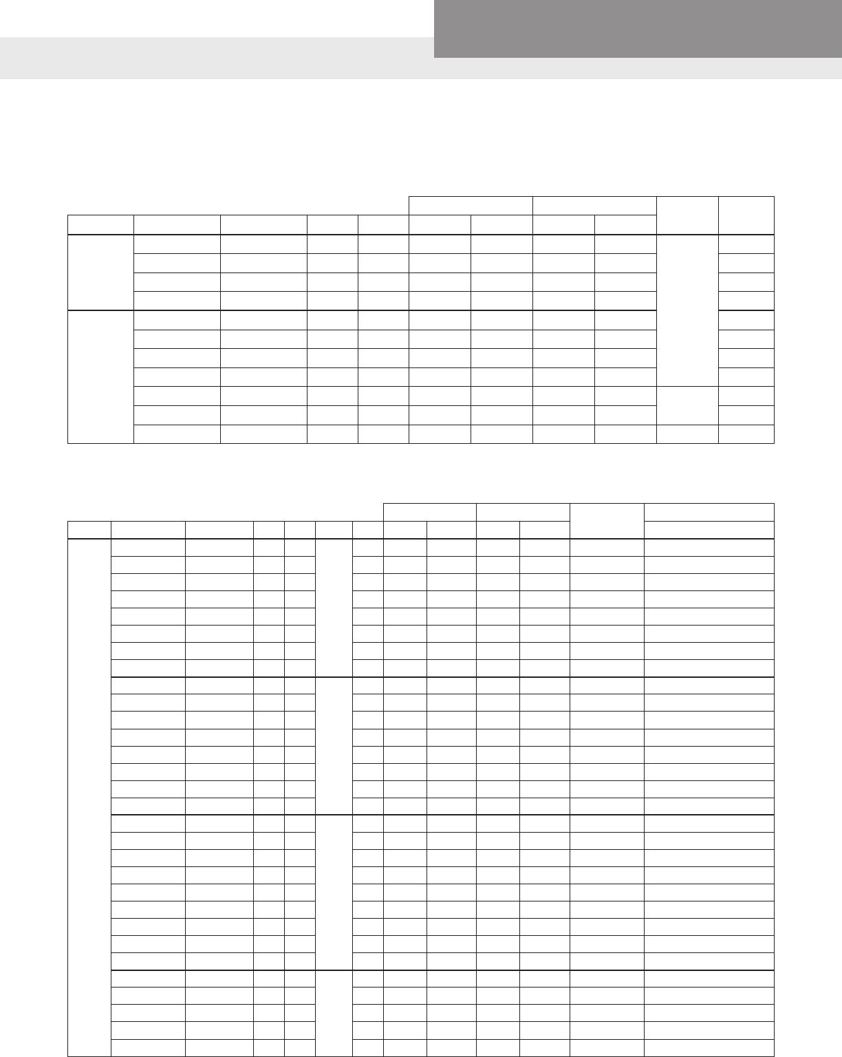
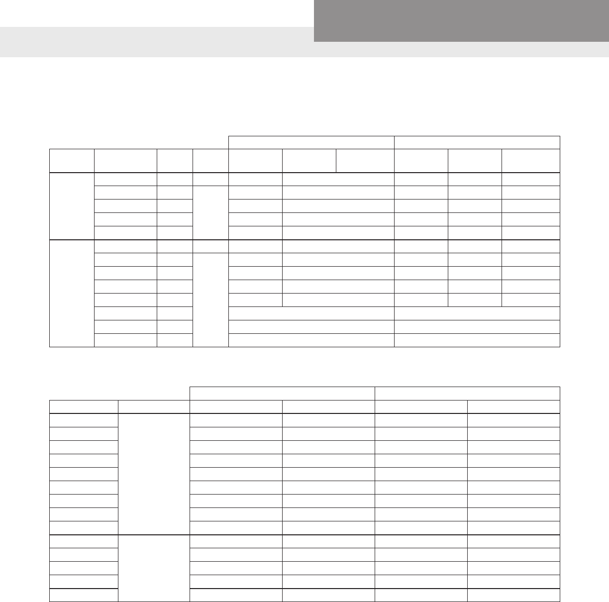
2-WIRE, 4" SINGLE PHASE ELECTRICAL DATA, 60 HZ, 3450 RPM
2-WIRE, 4" SINGLE PHASE ENGINEERING DATA
Efciency % Power Factor % Thrust
Rating
KVA
Code
Standard
Fuse
Dual Element
Time Delay
Fuse
Circuit
Breaker
Type Model HP Volts F.L. S.F. F.L. S.F.
2-Wire (PSC)
M05421 0.5 115 42% 54% 99% 99%
700 #
H 25 15 20
M05422 0.5 230 45% 59% 92% 97% J 15 10 10
M07422 0.75 230 51% 61% 98% 98% F 15 10 15
M10422 1.0 230 50% 59% 98% 98% F 20 15 20
M15422 1.5 230 57% 63% 98% 99% H 30 15 25
Rating Full Load Service Factor Locked
Rotor
Amps
Winding Resistance
Type Model RJ Ref. # HP KW Volts SF
Amps
(B or
Y/B/R)
Watts
Amps
(B or
Y/B/R)
Watts Main
(B-Y or B-B)
Start
(R-Y)
2-Wire (PSC)
M05421 50C201 0.5 0.37 115 1.6 7.9 910 9.8 1120 28 1.4-2.0 –
M05422 50C211 0.5 0.37 230 1.6 4.0 845 4.7 1050 16 6.1-7.2 –
M07422 75C211 0.75 0.55 230 1.5 5.0 1130 6.2 1400 18 5.9-6.9 –
M10422 100C211 1.0 0.75 230 1.4 6.7 1500 8.1 1800 24 4.2-5.2 –
M15422 150C211 1.5 1.1 230 1.3 9.0 2000 10.4 2350 43 1.8-2.4 –
3-WIRE, SINGLE PHASE 4" MOTORS - ENGINEERING DATA
Efciency % Power Factor % Thrust Rating KVA
Code
Type Model HP Volts F.L. S.F. F.L. S.F.
3-Wire
M05411 0.5 115 51 59 54 69
700 #
N
M05412 0.5
230
50 58 58 71 M
M07412 0.75 55 61 61 72 L
M10412 1.0 59 62 66 75 L
M15412 1.5 66 67 80 86 J
M20412 2 68 69 96 95 900 # G
M30412 3 72 72 96 97 G
M50412 5 71 71 97 98 1500 # E
PAGE 8
Residential Water Systems
CentriPro
SINGLE PHASE
Generation II Single Phase (Released April 2011)
3-WIRE, SINGLE PHASE 4" MOTORS - ELECTRICAL DATA, 60 HZ, 3450 RPM
Full Load Service Factor Locked
Rotor
Amps
Winding
Resistance Standard
Control
Box
Deluxe
Control
Box (Mag
Contactor)
Type Model RJ Ref. # HP KW Volts SF Amps Watts Amps Watts
Main
(B-Y or
B-B)
Start
(R-Y)
3-Wire (CSIR)
PREMIUM
M05411 50C301 0.5 0.37 115 1.6 Y – 8.8
B – 8.8
R – 0 675 Y – 10.9
B – 10.9
R – 0 980 44 1.0 -
1.4
2.5 -
3.1 CB05411 -
M05412 50C311 0.5 0.37
230
1.6 Y – 5.3
B – 5.3
R – 0 740 Y – 6.1
B – 6.1
R – 0 1050 21 5.1 -
6.1
12.4 -
13.7 CB05412 -
M07412 75C311 0.75 0.55 1.5 Y – 6.6
B – 6.6
R – 0 970 Y – 7.8
B – 7.8
R – 0 1350 32 2.6 -
3.3
10.4 -
11.7 CB07412 -
M10412 100C311 1.0 0.75 1.4 Y – 8.1
B – 8.1
R – 0 1215 Y – 9.4
B – 9.4
R – 0 1620 41 2.0 -
2.6
9.3 -
10.4 CB10412 -
3-Wire (CSCR) PREMIUM
M05412 50C311 0.5 0.37 1.6 Y – 4.2
B – 4.1
R – 1.8 715 Y – 4.8
B – 4.3
R – 1.8 960 21 5.1 -
6.1
12.4 -
13.7
CB-
05412CR -
M07412 75C311 0.75 0.55 1.5 Y – 4.8
B – 4.4
R – 2.5 940 Y – 6.0
B – 4.9
R – 2.3 1270 32 2.6 -
3.3
10.4 -
11.7
CB-
07412CR -
M10412 100C311 1.0 0.75 1.4 Y – 6.1
B – 5.2
R – 2.7 1165 Y – 7.3
B – 5.8
R – 2.6 1540 41 2.0 -
2.6
9.3 -
10.4
CB-
10412CR -
M15412 150C311 1.5 1.1 1.3 Y – 9.1
B – 8.2
R – 1.2 1660 Y – 10.9
B – 9.4
R – 1.1 2130 49 2.1 -
2.5
10.0 -
10.8
CB-
15412CR
CB-
15412MC
M20412 200C311 21.5 1.25 Y – 9.9
B – 9.1
R – 2.6 2170 Y – 12.2
B – 11.7
R – 2.6 2660 49 1.6 -
2.2
4.8 -
5.92
CB-
20412CR
CB-
20412MC
M30412 300C311 32.2 1.15 Y – 14.3
B – 12.0
R – 5.7 3170 Y – 16.5
B – 13.9
R – 5.6 3620 76 1.0 -
1.4
2.0 -
2.5
CB-
30412CR
CB-
30412MC
M50412 500C311 53.7 1.15 Y – 24.0
B – 19.1
R – 10.2 5300 Y – 27.0
B – 22.0
R – 10.0 6030 101 .6 - .8 1.3 -
1.7
CB-
50412CR
CB-
50412MC
3-WIRE, SINGLE PHASE 4" MOTORS - ENGINEERING DATA
Efciency % Power Factor % Thrust Rating KVA
Code
Type Model HP Volts F.L. S.F. F.L. S.F.
3-Wire
CSIR (QD)
M05411 0.5 115 57 62 65 78
700 #
M
M05412 0.5
230
52 58.5 61 75 L
M07412 0.75 60 64.5 64 76 L
M10412 1 63 66 66 76 L
3-Wire CSCR
M05412 0.5 54.5 61.5 77 87 L
M07412 0.75 62 69 86 91 L
M10412 1.0 66 71 86 91 L
M15412 1.5 68 69 81 87 J
M20412 2 70 70 89 91 900 # G
M30412 3 72 72 96 97 G
M50412 5 70.5 71 97 97.5 1500 # E

PAGE 9
Residential Water Systems
CentriPro
SINGLE PHASE
Generation II Single Phase (Released November 2015)
As part of Faradyne Motors' continual improvement process, further improvements have been made to Generation II mo-
tors in November 2015. Our pump model numbers and motor order number will not change. The Motor Nameplate for the
improved Generation II will have a - 01 sufx, example M05422 will be M05422 – 01, only on the Motor Nameplate not in our
catalog or price book. To decipher the November 2015 Generation II motors from the April 2011 Generation II motors, please
use the date code located on the motor. CentriPro motor date codes are 12 characters long, the rst character represents the
month and the fourth and fth character represent the year. The self-stick, Mylar motor data stickers we pack with our motors
and complete pumps will be updated with the new electrical data so that installers will know which motor is installed in the
well should service work ever be necessary.
2 WIRE PSC, SINGLE PHASE 4" MOTORS - ELECTRICAL DATA, 60 HZ, 3450 RPM
Rating Full Load Service Factor Locked
Rotor
Amps
Winding Resistance
Type Model RJ Ref. # HP KW Volts SF
Amps
(B or
Y/B/R)
Watts
Amps
(B or
Y/B/R)
Watts Main
(B-Y or B-B)
Start
(R-Y)
2-Wire (PSC)
M05421 50C201 0.5 0.37 115 1.6 8.1 890 10.2 1110 28 1.4 - 2.0 -
M05422 50C211 0.5 0.37 230 1.6 4.3 845 4.8 1035 16 6.1 - 7.2 -
M07422 75C211 0.75 0.55 230 1.5 5.0 1100 6.4 1375 18 5.9 - 6.9 -
M05422 100C211 1.0 0.75 230 1.4 6.7 1450 8.2 1770 23.5 4.2 - 5.2 -
M15422 150C211 1.5 1.1 230 1.3 9.1 1950 10.5 2300 43 1.8 - 2.4 -
2-WIRE, SINGLE PHASE 4" MOTORS - ENGINEERING DATA
Efciency % Power Factor
%Thrust
Rating
KVA
Code
Standard
Fuse
Dual
Element Time
Delay Fuse
Circuit
Breaker
Type Model HP Volts F.L. S.F. F.L. S.F.
2-Wire (PSC)
M05421 0.5 115 42 54 99 99
700 #
H 25 15 20
M05422 0.5 230 44 58 90 97 J 15 10 10
M07422 0.75 230 51 61 99 99 F 15 10 15
M05422 1.0 230 52 59 99 99 F 20 15 20
M15422 1.5 230 58 63 98 99 H 30 20 25
3-WIRE, SINGLE PHASE 4" MOTORS - ELECTRICAL DATA, 60 HZ, 3450 RPM
Rating Full Load Service
Factor Locked
Rotor
Amps
Winding
Resistance Standard
Control
Box
Deluxe
Control
Box (Mag
Contactor)
Type Model RJ Ref.
#HP KW Volts SF
Amps
(B or
Y/B/R)
Watts
Amps
(B or
Y/B/R)
Watts
Main
(B-Y or
B-B)
Start
(R-Y)
3-Wire (CSIR)
PREMIUM
M05411 50C301 0.5 0.37 115 1.6 9.8/9.8/0 670
11.6/11.6/0
980 44 1.0 - 1.4 2.5 - 3.1 CB05411 -
M05412 50C311 0.5 0.37 230 1.6 5.7/5.7/0 735
6.3/6.3/0
1035 20.5 5.1 - 6.1 12.4 -
13.7 CB05412 -
M07412 75C311 0.75 0.55 230 1.5 6.7/6.7/0 940
7.9/7.9/0
1335 32 2.6 - 3.3 10.4 -
11.7 CB07412 -
M10412 100C311 10.75 230 1.4 8.5/8.5/0 1175
9.5/9.5/0
1590 41 2.0 - 2.6 9.3 - 10.4 CB10412 -
3-Wire (CSCR) PREMIUM
M05412 50C311 0.5 0.37 230 1.6 4.4/4.3/1.9 715
5.0/4.5/1.9
950 21 5.1 - 6.1 12.4 -
13.7 CB05412CR -
M07412 75C311 0.75 0.55 230 1.5 4.6/4.6/2.6 920
6.1/5.1/2.6
1235 32 2.6 - 3.3 10.4 -
11.7 CB07412CR -
M10412 100C311 1.0 0.75 230 1.4 6.2/6.0/3.6 1165
7.4/6.3/3.3
1490 41 2.0 - 2.6 9.3 - 10.4 CB10412CR -
M15412 150C311 1.5 1.1 230 1.3 9.2/8.7/1.2 1660
11.0/9.9/1.2
2110 49 2.1 - 2.5 10.0 -
10.8 CB15412CR CB15412MC
M20412 200C311 2.0 1.5 230 1.25 9.9/9.1/2.6 2170
12.2/11.7/2.6
2660 49 1.6 - 2.2 4.8 - 5.9 CB20412CR CB20412MC
M30412 300C311 3.0 2.2 230 1.15 14.3/12.0/5.7 3170
16.5/13.9/5.6
3620 76 1.0 - 1.4 2.0 - 2.5 CB30412CR CB30412MC
M50412 500C311 5.0 3.7 230 1.15 24/19.1/10.2 5300
27.0/22.0/10.0
6030 101 .6 - .8 1.3 - 1.7 CB50412CR CB50412MC
PAGE 10
Residential Water Systems
CentriPro
3-WIRE, SINGLE PHASE 4" MOTORS - ENGINEERING DATA
Efciency % Power Factor % Thrust
Rating
KVA
Code
Type Model RJ REF # HP Volts F.L. S.F. F.L. S.F.
3-Wire
(CSIR)
PREMIUM
M05411 50C301 0.5 115 55.5 61 63 77
700 #
M
M05412 50C311 0.5 230 51 58 60 75 L
M07412 75C311 0.75 230 60 63 64 78 L
M10412 100C311 1 230 63.5 66 63 76 L
3-Wire (CSCR)
PREMIUM
M05412 50C311 0.5 230 52 63 75 86 L
M07412 75C311 0.75 230 61 68 86 93 L
M10412 100C311 1.0 230 64 70 85 91 L
M15412 150C311 1.5 230 68 69 82 87 J
M20412 200C311 2.0 230 68 69 96 95 900 # G
M30412 300C311 3.0 230 72 72 96 97 G
M50412 500C311 5.0 230 70.5 71 97 97.5 1500 # E
SINGLE PHASE
Generation II Single Phase (Released November 2015)
THREE PHASE (Released April 2011)
ELECTRICAL DATA, 60 HZ, 3450 RPM, 4" MOTORS
Full Load Service Factor Locked
Rotor Amps
Winding Resistance
Type CentriPro # RJ Ref. # HP KW Volts SF Amps Watts Amps Watts PH-PH
4" 3-Phase (PREMIUM)
M05430 50C323 0.5 0.37
200
1.6 2.9 600 3.4 870 22 4.1 - 5.2
M07430 75C323 0.75 0.55 1.5 3.8 812 4.5 1140 32 2.6 - 3.0
M10430 100C323 10.75 1.4 4.6 1150 5.5 1500 29 3.4 - 3.9
M15430 150C323 1.5 1.1 1.3 6.3 1560 7.2 1950 40 1.9 - 2.5
M20430 200C323 21.5 1.25 7.5 2015 8.8 2490 51 1.4 - 2.0
M30430 300C323 32.2 1.15 10.9 2890 12.0 3290 71 1.2 - 1.5
M50430 500C323 53.7 1.15 18.3 4850 20.2 5515 113 0.7 - 0.9
M75430 750C323 7.5 5.5 1.15 27.0 7600 30.0 8800 165 0.4 - 0.6
M05432 50C313 0.5 0.37
230
1.6 2.4 610 2.9 880 17.3 5.7 - 7.2
M07432 75C313 0.75 0.55 1.5 3.3 850 3.9 1185 27 3.3 - 4.3
M10432 100C313 10.75 1.4 4.0 1090 4.7 1450 26.1 4.1 - 5.1
M15432 150C313 1.5 1.1 1.3 5.2 1490 6.1 1930 32.4 2.8 - 3.4
M20432 200C313 21.5 1.25 6.5 1990 7.6 2450 44 2.2 - 2.8
M30432 300C313 32.2 1.15 9.2 2880 10.1 3280 58.9 1.6 - 2.0
M50432 500C313 53.7 1.15 15.7 4925 17.5 5650 93 .9 - 1.3
M75432 750C313 7.5 5.5 1.15 24 7480 26.4 8570 140 .5 - .9
M05434 50C353 0.5 0.37
460
1.6 1.3 610 1.5 875 9 23.6 - 26.1
M07434 75C353 0.75 0.55 1.5 1.7 820 2.0 1140 14 14.4 - 16.2
M10434 100C353 10.75 1.4 2.2 1145 2.5 1505 13 17.8 - 18.8
M15434 150C353 1.5 1.1 1.3 2.8 1560 3.2 1980 16.3 12.3 - 13.1
M20434 200C353 21.5 1.25 3.3 2018 3.8 2470 23 7.5 - 9.3
M30434 300C353 32.2 1.15 4.8 2920 5.3 3320 30 6.3 - 7.7
M50434 500C353 53.7 1.15 7.6 4810 8.5 5530 48 3.9 - 4.9
M75434 750C353 7.5 5.5 1.15 12.2 7400 13.5 8560 87 2.1 - 2.7
M100434 1000C353 10 7.5 1.15 15.6 9600 17.2 11000 110 1.8 - 2.2
M15437 150C363 1.5 1.1
575
1.3 2.0 1520 2.4 1950 11.5 19.8 - 20.6
M20437 200C363 21.5 1.25 2.7 1610 3.3 2400 21 10.2 - 12.5
M30437 300C363 32.2 1.15 3.7 2850 4.1 3240 21.1 10.2 - 12.5
M50437 500C363 53.7 1.15 7.0 5080 7.6 5750 55 3.6 - 4.2
M75437 750C363 7.5 5.5 1.15 9.1 7260 10.0 8310 55 3.6 - 4.2
PAGE 11
Residential Water Systems
CentriPro
THREE PHASE (Released April 2011)
4" MOTORS - ENGINEERING DATA
Efciency
%
Thrust
Rating
KVA
Code
Standard Fuse Dual Element
Time Delay Circuit Breaker
Type CentriPro
#HP Volts F.L. S.F.
Meets
NEC
Based
on FL
Max
Value
Based
on SFA
Meets
NEC
Based
on FL
Max
Value
Based
on SFA
Meets
NEC
Based
on FL
Max
Value
Based
on SFA
4" 3-Phase (PREMIUM)
M05430 0.5
200
62 68
700 #
R 10 15 6 10 10 10
M07430 0.75 69 74 R 15 15 10 15 10 15
M10430 166 70 M 15 20 10 10 10 15
M15430 1.5 72 74 L 20 25 10 15 15 20
M20430 274 75 900 # K 25 30 15 20 20 25
M30430 377 77 K 35 40 20 25 30 35
M50430 576 76 1500 # J 60 70 35 40 50 60
M75430 7.5 74 74 J 80 90 50 60 70 80
M05432 0.5
230
61 68
700 #
R 6 10 6 6 6 10
M07432 0.75 66 71 R 6 15 6 10 6 10
M10432 169 72 M 10 15 6 10 10 15
M15432 1.5 75 76 K 15 20 10 15 15 20
M20432 275 75 900 # K 15 25 15 15 20 20
M30432 377 77 J 25 35 15 20 25 30
M50432 576 76 1500 # J 45 60 30 35 40 45
M75432 7.5 75 75 J 70 80 45 50 60 70
M05434 0.5
460
61 68
700 #
R363336
M07434 0.75 69 73 R 3 10 6 6 3 6
M10434 165 69 M 6 10 3 6 6 10
M15434 1.5 72 73 K 10 10 6 6 6 10
M20434 274 75 900 # L 15 15 6 10 10 10
M30434 376 77 J 15 20 10 10 15 15
M50434 577 77
1500 #
J 25 30 15 20 15 25
M75434 7.5 76 76 L 40 50 25 30 30 35
M100434 10 79 80 K 45 60 25 35 35 45
M15437 1.5
575
73 74 700 # J 6 10 3 6 6 10
M20437 278 78 900 # M 10 10 6 6 10 10
M30437 378 78 J 10 15 10 10 10 15
M50437 574 75 1500 # M 20 25 15 15 20 20
M75437 7.5 77 77 J 25 35 20 20 25 30
PAGE 12
Residential Water Systems
CentriPro
THREE PHASE (Released November 2015)
As part of Faradyne Motors' continual improvement process, further improvements have been made to CentriPro Three Phase
motors in November 2015. Our pump model numbers and motor order number will not change. To decipher the November
2015 motors from the previous three phase motors, please use the date code located on the motor. CentriPro motor date
codes are 12 characters long, the rst character represents the month and the fourth and fth character represent the year.
The self-stick, Mylar motor data stickers we pack with our motors and complete pumps will be updated with the new electrical
data so that installers will know which motor is installed in the well should service work ever be necessary.
ELECTRICAL DATA, 60 HZ, 3450 RPM, 4" MOTORS
Full Load Service Factor Locked
Rotor
Amps
Winding Resistance
Type CentriPro # RJ Ref. # HP KW Volts SF Amps Watts Amps Watts PH-PH
4" 3-Phase (PREMIUM)
M05430 50C323 0.5 0.37
200
1.6 2.9 600 3.5 860 22 4.1 - 5.2
M07430 75C323 0.75 0.55 1.5 3.9 820 4.7 1150 30 2.8 - 3.7
M10430 100C323 1.0 0.75 1.4 4.8 1120 5.7 1470 34 2.2 - 3.1
M15430 150C323 1.5 1.1 1.3 6.6 1650 7.6 1950 40 1.9 - 2.5
M20430 200C323 2.0 1.5 1.25 8.0 1960 9.3 2455 51 1.4 - 2.0
M30430 300C323 3.0 2.20 1.15 10.9 2890 12.0 3290 71 1.2 - 1.5
M50430 500C323 5.0 3.70 1.15 18.3 4850 20.2 5515 113 .7 - .9
M75430 750C323 7.5 5.50 1.15 27.0 7600 30.0 8800 165 .4 - .6
M05432 50C313 0.5 0.37
230
1.6 2.4 575 3.0 860 18 5.7 - 7.2
M07432 75C313 0.75 0.55 1.5 3.3 805 4.0 1160 27 3.3 - 4.3
M10432 100C313 1.0 0.75 1.4 4.1 1070 4.9 1440 26 3.2 - 4.2
M15432 150C313 1.5 1.1 1.3 5.8 1550 6.6 1950 36 2.5 - 3.1
M20432 200C313 2.0 1.5 1.25 6.7 1965 8.0 2465 44 2.2 - 2.8
M30432 300C313 3.0 2.2 1.15 9.2 2880 10.1 3280 59 1.6 - 2.0
M50432 500C313 5.0 3.7 1.15 15.7 4925 17.5 5650 93 .9 - 1.3
M75432 750C313 7.5 5.5 1.15 24.0 7480 26.4 8570 140 .5 - .9
M05434 50C353 0.5 0.37
460
1.6 1.3 620 1.5 865 9 23.6 - 26.1
M07434 75C353 0.75 0.55 1.5 1.7 825 2.0 1140 14 14.4 - 16.2
M10434 100C353 1.0 0.75 1.4 2.2 1140 2.5 1460 15 16.8 - 18.6
M15434 150C353 1.5 1.1 1.3 3.0 1540 3.4 1960 16 9.5 - 10.5
M20434 200C353 2.0 1.5 1.25 3.6 1960 4.1 2440 23 7.5 - 9.3
M30434 300C353 3.0 2.20 1.15 4.8 2920 5.3 3320 30 6.3 - 7.7
M50434 500C353 5.0 3.70 1.15 7.6 4810 8.5 5530 48 3.9 - 4.9
M75434 750C353 7.5 5.50 1.15 12.2 7400 13.5 8560 87 2.1 - 2.7
M100434 1000C353 10.0 7.50 1.15 15.6 9600 17.2 11000 110 1.8 - 2.2
M15437 150C363 1.5 1.1
575
1.3 2.3 1540 2.6 1970 15 15.6 - 17.3
M20437 200C363 2.0 1.50 1.25 2.7 1610 3.3 2400 21 10.2 - 12.5
M30437 300C363 3.0 2.20 1.15 3.7 2850 4.1 3240 21 10.2 - 12.5
M50437 500C363 5.0 3.7 1.15 7.0 5080 7.6 5750 55 3.6 - 4.2
M75437 750C363 7.5 5.5 1.15 9.1 7260 10.0 8310 55 3.6 - 4.2

PAGE 13
Residential Water Systems
CentriPro
THREE PHASE (Released November 2015)
4" MOTORS - ENGINEERING DATA
Efciency
%
Thrust
Rating
KVA
Code
Standard Fuse Dual Element
Time Delay Circuit Breaker
Type CentriPro
#HP Volts F.L. S.F.
Meets
NEC
Based
on FL
Max
Value
Based
on SFA
Meets
NEC
Based
on FL
Max
Value
Based
on SFA
Meets
NEC
Based
on FL
Max
Value
Based
on SFA
4" 3-Phase (PREMIUM)
M05430 0.5
200
64.0 69.5 700 R 10 15 6 10 10 10
M07430 0.75 68.0 73.0 700 R 15 15 10 15 10 15
M10430 1.0 69.0 73.0 700 N 15 20 10 10 10 15
M15430 1.5 73.0 74.5 700 L 20 25 10 15 15 20
M20430 2.0 76.0 76.0 900 K 25 30 15 20 20 25
M30430 3.0 77.0 77.0 900 K 35 40 20 25 30 35
M50430 5.0 76.0 76.0 1500 J 60 70 35 40 50 60
M75430 7.5 74.0 74.0 1500 J 80 90 50 60 70 80
M05432 0.5
230
65 69.5 700 R 6 10 6 6 6 10
M07432 0.75 69.5 72.5 700 R 6 15 6 10 6 10
M10432 170 72.5 700 M 10 15 6 10 10 15
M15432 1.5 72 74.5 700 L 15 20 10 15 15 20
M20432 276 75.5 900 K 15 25 15 15 20 20
M30432 377 77 900 J 25 35 15 20 25 30
M50432 576 76 1500 J 45 60 30 35 40 45
M75432 7.5 75 75 1500 J 70 80 45 50 60 70
M05434 0.5
460
60.5 69 700 R 3 6 3 3 3 6
M07434 0.75 68 73.5 700 R 3 10 6 6 3 6
M10434 165.5 71.5 700 N 6 10 3 6 6 10
M15434 1.5 73 74 700 L 10 10 6 6 6 10
M20434 276 76.5 900 L 15 15 6 10 10 10
M30434 377 77 900 J 15 20 10 10 15 15
M50434 577 77 1500 J 25 30 15 20 15 25
M75434 7.5 76 76 1500 L 40 50 25 30 30 35
M100434 10 79 80 1500 K 45 60 25 35 35 45
M15437 1.5
575
73 74 700 K 6 10 3 6 6 10
M20437 278 78 900 M 10 10 6 6 10 10
M30437 378 78 900 J 10 15 10 10 10 15
M50437 574 75 1500 M 20 25 15 15 20 20
M75437 7.5 77 77 1500 J 25 35 20 20 25 30

PAGE 14
Residential Water Systems
CentriPro
WIRE SIZING
4" PREMIUM MOTORS – 2-WIRE SINGLE PHASE (All Generations)
4" PREMIUM MOTORS – 3-WIRE SINGLE PHASE (All Generations)
Motor Lead Lengths - Faradyne 2 Wire Motors - Based on Service Factor Amps,
30ºC Ambient & 5% Voltage Drop
Motor Rating
Volts HP kW FLA SFA 14 12 10 8 6 4 2 1/0 2/0 3/0 4/0
115 ½ 0.37 8.1 10.2 107 171 273 432 672 1071 1700 2703 3411 4305 5424
230 ½ 0.37 4.3 4.8 457 726 1158 1835 2855 4551 7225 11489
230 ¾ 0.55 5.0 6.4 342 545 869 1376 2141 3413 5419 8617 10871
230 1 0.75 6.7 8.2 241 383 611 968 1506 2400 3811 6060 7646 9652
230 1½ 1.1 9.1 10.5 199 317 505 801 1246 1986 3153 5013 6325 7985
Motor Lead Lengths - Faradyne 3 Wire Motors - Based on Service Factor Amps,
30ºC Ambient, & 5% Voltage Drop
Motor Rating 60ºC & 75ºC Insulation - AWG Copper Wire Size
Volts HP kW FLA SFA 14 12 10 8 6 4 2 1/0 2/0 3/0 4/0
CSIR Control Boxes
115 1/2 0.37 9.8 11.6 87 138 221 349 544 867 1376 2188 2716 3485 4391
230
1/2 0.37 5.7 6.3 348 553 883 1398 2175 3467 5505 8753
3/4 0.55 6.7 7.9 264 420 670 1061 1651 2632 4178 6644 8383
1 0.75 8.5 9.5 226 359 573 908 1413 2252 3575 5685 7173
CSCR Control Boxes
230
1/2 0.37 4.4 5.0 348 553 883 1398 2175 3467 5505 8753
3/4 0.55 4.6 6.1 264 420 670 1061 1651 2632 4178 6644 8383
1 0.75 6.2 7.4 226 359 573 908 1413 2252 3575 5685 7173
1 1/2 1.1 9.2 11.0 197 314 501 793 1246 1986 3124 4968 6268
2 1.5 9.9 12.2 180 286 456 722 1123 1790 2843 4520 5703
3 2.2 14.3 16.5 133 211 337 534 830 1324 2102 3342 4217 5323
5 3.7 24.0 27.0 206 326 507 809 1284 2042 2577 3253
PAGE 15
Residential Water Systems
CentriPro
WIRE SIZING
Motor Lead Lengths - Faradyne 3-Phase Motors - Based on Service Factor Amps,
30ºC Ambient, & 5% Voltage Drop
Motor Rating 60ºC & 75ºC Insulation - AWG Copper Wire Size
Volts HP kW FLA SFA 14 12 10 8 6 4 2 1/0 2/0 3/0 4/0
200
.5 0.37 2.9 3.5 629 1000 1595 2526 3931
.75 .55 3.8 4.5 423 674 1074 1702 2648
1.75 4.6 5.5 346 551 879 1392 2166 3454
1.5 1.1 6.3 7.2 265 421 672 1064 1655 2638
21.5 7.5 8.8 217 344 549 870 1354 2158 3427 5449
32.2 10.9 12.0 159 253 403 638 993 1583 2513 3996
53.7 18.3 20.2 94 150 239 379 590 940 1493 2374 2995 3781 4764
7.5 5.5 27.0 30.0 64 101 161 255 397 633 1005 1598 2017 2546 3207
230
.5 .37 2.4 2.9 756 1202 1917 3037 4725 7532
.75 .55 3.3 3.9 562 894 1426 2258 3513 5601 8892
1.75 4 4.7 466 742 1183 1874 2915 4648 7379
1.5 1.1 5.2 6.1 359 571 912 1444 2246 3581 5685 9040
21.5 6.5 7.6 288 459 732 1159 1803 2874 4563 7256 9155
32.2 9.2 10.1 217 345 551 872 1357 2163 3434 5460 6889 8696 10956
53.7 15.7 17.5 318 503 783 1248 1982 3151 3976 5019 6323
7.5 5.5 24 26.4 334 519 827 1314 2089 2635 3327 4192
460
.5 .37 1.3 1.5 2922 4648 7414
.75 .55 1.7 2.0 2191 3486 5560 8806
1.75 2.2 2.5 1753 2789 4448 7045
1.5 1.1 2.8 3.2 1370 2179 3475 5504
21.5 3.3 3.8 1153 1835 2926 4635 7212
32.2 4.8 5.3 827 1315 2098 3323 5171
53.7 7.6 8.5 516 820 1308 2072 3224 5140
7.5 5.5 12.2 13.5 325 516 824 1305 2030 3236 5138
10 7.5 15.6 17.2 255 405 647 1024 1593 2540 4033
575
1.5 1.1 2.0 2.4 2283 3631 5792
21.5 2.7 3.3 1660 2641 4212 6671
32.2 3.7 4.1 1336 2126 3390 5370
53.7 7.0 7.6 721 1147 1829 2897 4507
7.5 5.5 9.1 10.0 548 871 1390 2202 3426
3Ø 4" CENTRIPRO MOTOR WIRE CHART (All Generations)
PAGE 16
Residential Water Systems
CentriPro
WEIGHTS AND DIMENSIONS
2-WIRE & 3-WIRE WEIGHTS AND DIMENSIONS
Length (L) In. Weight (lbs)
Type CentriPro
Order No. HP Volts Gen I Gen II Gen II -
Nov. 2015 Gen I Gen II Gen II -
Nov. 2015
2-Wire
(PSC)
Premium
M05421 .5 115 11 10.5 19 18 18.1
M05422 .5
230
11 10.5 19 18 18.1
M07422 .75 12.4 11.9 23 22 21.4
M10422 1 13.3 12.5 25 24 23.2
M15422 1.5 14.9 14.2 29 28 27.3
3-Wire
Premium
M05411 .5 115 10 9.6 19 18 17.9
M05412 .5
230
9.7 9.2 18 17 16.7
M07412 .75 10.8 10.3 22 20 19.8
M10412 1 11.7 11.2 23 22 22
M15412 1.5 13.6 12.8 28 26 26
M20412 2 15.1 31
M30412 3 18.3 40
M50412 5 27.7 70
THREE-PHASE, 4" MOTOR, LENGTHS AND WEIGHTS
Length Weight
HP Volts Inches mm lb. kg.
0.5
200
230
460
10.0 254 19 8.6
0.75 10.8 275 22 9.7
1.0 11.7 297 23 10.4
1.5 11.7 297 23 10.4
2.0 13.8 351 28 12.7
3.0 15.3 389 32 14.5
5.0 21.7 550 55 24.9
7.5 27.7 703 70 31.8
10.0 30.7 780 78 35.4
1.5
575
11.7 297 23 10.4
2.0 15.3 389 32 14.5
3.0 15.3 389 32 14.5
5.0 27.7 703 70 31.8
7.5 27.7 703 70 31.8
PAGE 17
Residential Water Systems
CentriPro
USING TWO DIFFERENT CABLE SIZES
Customers sometimes desire to use two or more wire sizes on a pump installation. This is acceptable as long as
the maximum cable length ratings are not exceeded. The data below describes how to safely accomplish the
task. The cable lengths in the wire sizing charts represent 100% of the allowable length for each wire size. Never
use more than 100% of any length shown in the table.
The Three-Wire, Single Phase Motor Wire Chart will be used in this example. See page 8.
Installation Data:
• 2 HP, 230V, 1Ø, 3-Wire Motor
• 150 Ft of #12 wire buried between the home (service entrance) and the well
• Pump is set at 340 feet
• Total wire length is 490 feet
Refer to 3-Wire Motor Lead Length Chart
• Select row for 2 HP, 230V, 1Ph Motor
• Maximum wire lengths are:
• #12 - 286’ • #10 - 456’ • # 8 - 722’
• Allowable Drop Cannot Exceed 100% of Any Length or Combination of Lengths
The existing 150 feet of #12 underground wire uses 150’/286’ = 52.4% of the allowable length.
100% - 52.4% = 47.6% of another wire available to use. Which wire will use ≤ 47.6% of its allowable length to
run 340’.
340’/456’ = 74.5% of #10 - 74.5% + 52.4% = 126.9% - over 100% is not allowable
340’/722’ = 47.1% of #8 - 47.1% + 52.4% = 99.5% which is allowable
On this application we can use 150’ of #12 with 340’ of #8.
The formula is: Actual Length 1 + Actual length 2 ≤ 1 or ≤ 100%
Maximum Allowed Maximum Allowed
Using this formula it is possible to size wire using 2 or more different wire sizes.

PAGE 18
Residential Water Systems
CentriPro
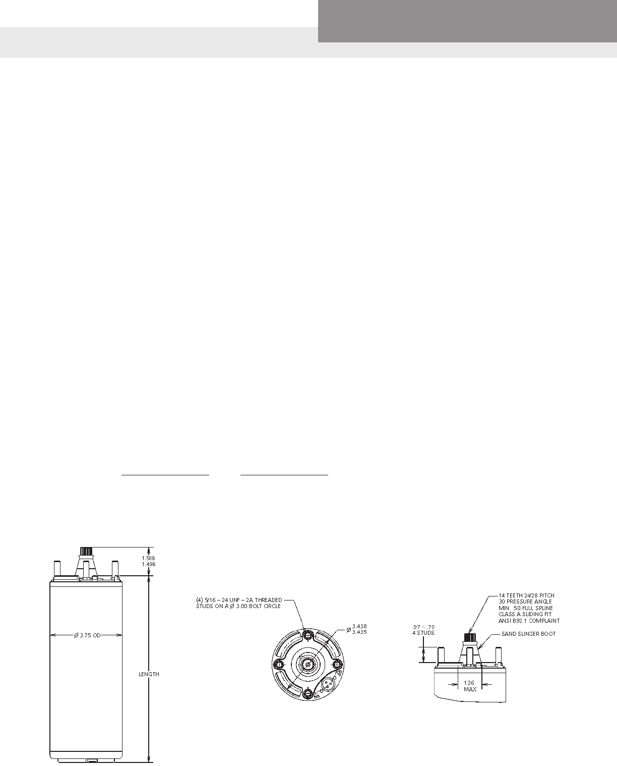
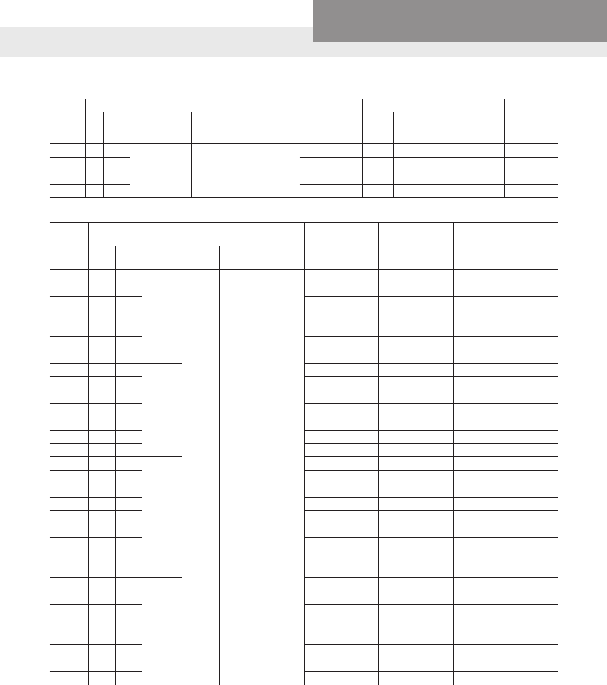
CENTRIPRO (HITACHI) 6-10” THREE PHASE MOTORS
6" SINGLE PHASE MOTORS AND REQUIRED CONTROL BOXES
Motor
Order No. HP KW Volts Phase Motor Dia. vs.
Flange Dia. SF
Rated Input Service Factor Full Load
Speed
(RPM)
Locked
Rotor
Amps
Amps Watts Amps Watts
6M058 5 3.7 200
3
6" x 6"
1.15
17.5 4910 19.5 5610 3468 124
6M052 5 3.7 230 15.0 4857 17.0 5520 3468 110
6M054 5 3.7 460 7.5 4857 8.5 5520 3468 55
6M078 7.5 5.5 200 25.4 7180 28.5 8230 3479 158
6M072 7.5 5.5 230 22.0 7127 26.0 8140 3479 144
6M074 7.5 5.5 460 11.0 7127 13.0 8140 3479 72
6M108 10 7.5 200 33.3 9360 37.2 10700 3480 236
6M102 10 7.5 230 29.0 9407 33.0 10730 3480 208
6M104 10 7.5 460 14.5 9407 16.5 10730 3480 104
6M158 15 11 200 47.4 13700 53.5 15710 3483 347
6M152 15 11 230 42.0 13700 46.0 15800 3483 320
6M154 15 11 460 21.0 13700 23.0 15800 3483 160
6M208 20 15 200 61.2 18040 69.5 20820 3461 431
6M202 20 15 230 54.0 17930 60.0 20650 3461 392
6M204 20 15 460 27.0 17930 30.0 20650 3461 196
6M258 25 18.5 200 77.3 22740 87.5 26190 3479 578
6M252 25 18.5 230 68.0 22470 76.0 25800 3479 530
6M254 25 18.5 460 34.0 22470 38.0 25800 3479 265
6M308 30 22 200 91.8 27000 104.0 31120 3476 674
6M302 30 22 230 82.0 27130 94.0 31160 3476 610
6M304 30 22 460 41.0 27130 47.0 31160 3476 305
6M404 40 30 460 56.0 35530 61.0 41100 3447 420
66M504 50 37 460 70.0 45210 79.0 52380 3398 465
86M504 50 37 460 8" x 6" 65.0 44501 73.0 50891 3484 435
86M604 60 45 460 80.0 51866 90.0 59576 3491 556
8M754 75 55 460
8" x 8"
96.0 65900 109.0 76100 3489 675
8M1004 100 75 460 127.0 87600 145.0 101300 3478 855
8M1254 125 90 460 161.0 110800 180.0 126000 3477 1122
8M1504 150 110 460 197.0 130700 220.0 152000 3472 1331
10M2004 200 150 460 10 "x 10" 235.0 171100 270.0 198600 3478 1260
5-30 HP, 3 Phase 230 and 460 Motors have adjustable voltage feature, change voltage plugs to convert from 230V to 460V operation.
Spare Change Plug Order No's are: PLUG-230V or PLUG-460V
Motor
Order
No.
HP KW Volts Phase
Motor Dia.
vs. Flange
Dia.
SF
Rated Input Service Factor Full Load
Speed
(RPM)
Locked
Rotor
Amps
Control Box
Order No.
Amps Watts Amps Watts
6M051 5 3.7
230 1 6” x 6” 1.15
24 4987 27.5 5735 3492 124 CB05MC3R
6M071 7.5 5.5 36 7675 41 8950 3448 167 CB07MC3R
6M101 10 7.5 50 10135 58 11830 3452 202 CB10MC3R
6M151 15 11 72 15180 85 18050 3424 275 CB15MC3R
PAGE 19
Residential Water Systems
CentriPro
CENTRIPRO (HITACHI) 6-10” THREE PHASE MOTORS
Motor HP kW Volts Phase F.L. KVA Line - Line Time Delay Fuse
Order No. Efciency % Code Resistance Standard Dual Element
6M058 5 3.7 200 75.9 K 0.618 50 25
6M052 5 3.7 230 76.8 K 0.806 45 20
6M054 5 3.7 460 76.8 K 3.050 25 10
6M078 7.5 5.5 200 77.9 J 0.504 80 40
6M072 7.5 5.5 230 78.5 J 0.651 70 30
6M074 7.5 5.5 460 78.5 J 2.430 35 15
6M108 10 7.5 200 79.7 K 0.315 100 50
6M102 10 7.5 230 79.3 K 0.448 90 40
6M104 10 7.5 460 79.3 K 1.619 45 20
6M158 15 11 200 81.7 K 0.213 175 70
6M152 15 11 230 81.7 K 0.312 150 60
6M154 15 11 460 81.7 K 1.074 70 30
6M208 20 15 200 82.7 J 0.189 200 90
6M202 20 15 230 83.2 J 0.258 175 70
6M204 20 15 460 3 83.2 J 0.861 90 35
6M258 25 18.5 200 82.0 K 0.146 250 110
6M252 25 18.5 230 83.0 K 0.210 225 90
6M254 25 18.5 460 83.0 K 0.666 110 45
6M308 30 22 200 82.9 J 0.119 300 125
6M302 30 22 230 82.5 K 0.166 250 100
6M304 30 22 460 82.5 K 0.554 125 50
6M404 40 30 460 83.7 K 0.358 175 100
66M504 50 37 460 82.5 J 0.308 225 125
86M504 50 37 460 84.1 H 0.331 225 125
86M604 60 45 460 86.2 J 0.278 250 150
8M754 75 55 460 86.9 H 0.218 300 175
8M1004 100 75 460 86.6 H 0.164 400 225
8M1254 125 90 460 86.9 J 0.132 500 300
8M1504 150 110 460 86.8 H 0.115 600 350
10M2004 200 150 460 87.2 F 0.0929 800 450
6" SINGLE PHASE MOTORS
Motor HP kW Volts Phase F.L. KVA Resistance - Ohms
Order No. Efciency % Code R - Y B - Y R - B
6M051 5 3.7 74.8 G 2.172 0.512 2.627
6M071 7.5 5.5 230 1 72.9 F 1.401 0.400 1.774
6M101 10 7.5 73.6 E 1.052 0.316 1.310
6M151 15 11 73.7 D 0.678 0.230 0.850
PAGE 20
Residential Water Systems
CentriPro
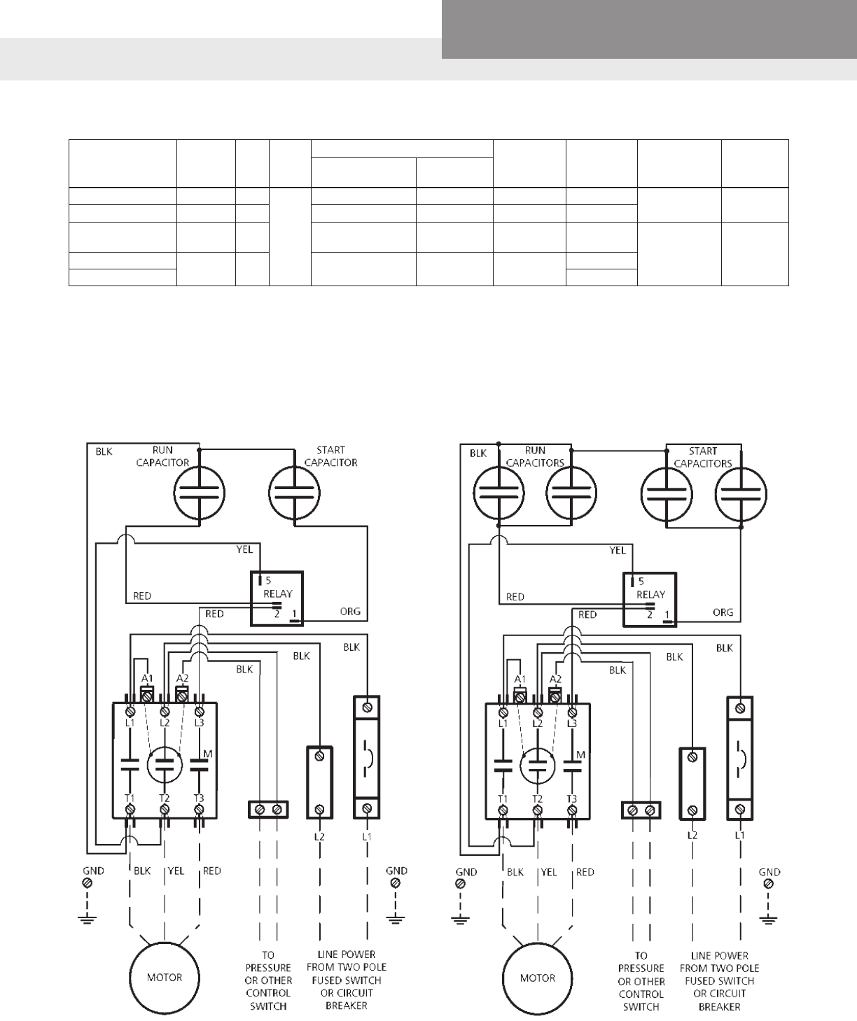
➀ Overload circuit breaker is rated at 100 amps versus 90 amp standard in CB15MC. Use in areas with high ambient temperatures to reduce
nuisance tripping.
* Use these control boxes on only CentriPro (Hitachi) motors. Franklin Electric control boxes will not work and will void the CentriPro warranty.
Do not use these control boxes on Franklin Electric 6" motors as the overloads and capacitors are not the same as used by FE, using these
will void FE's warranty.
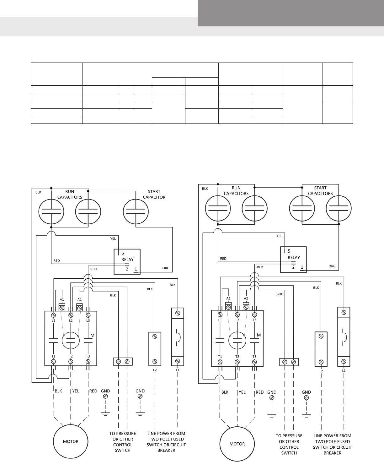
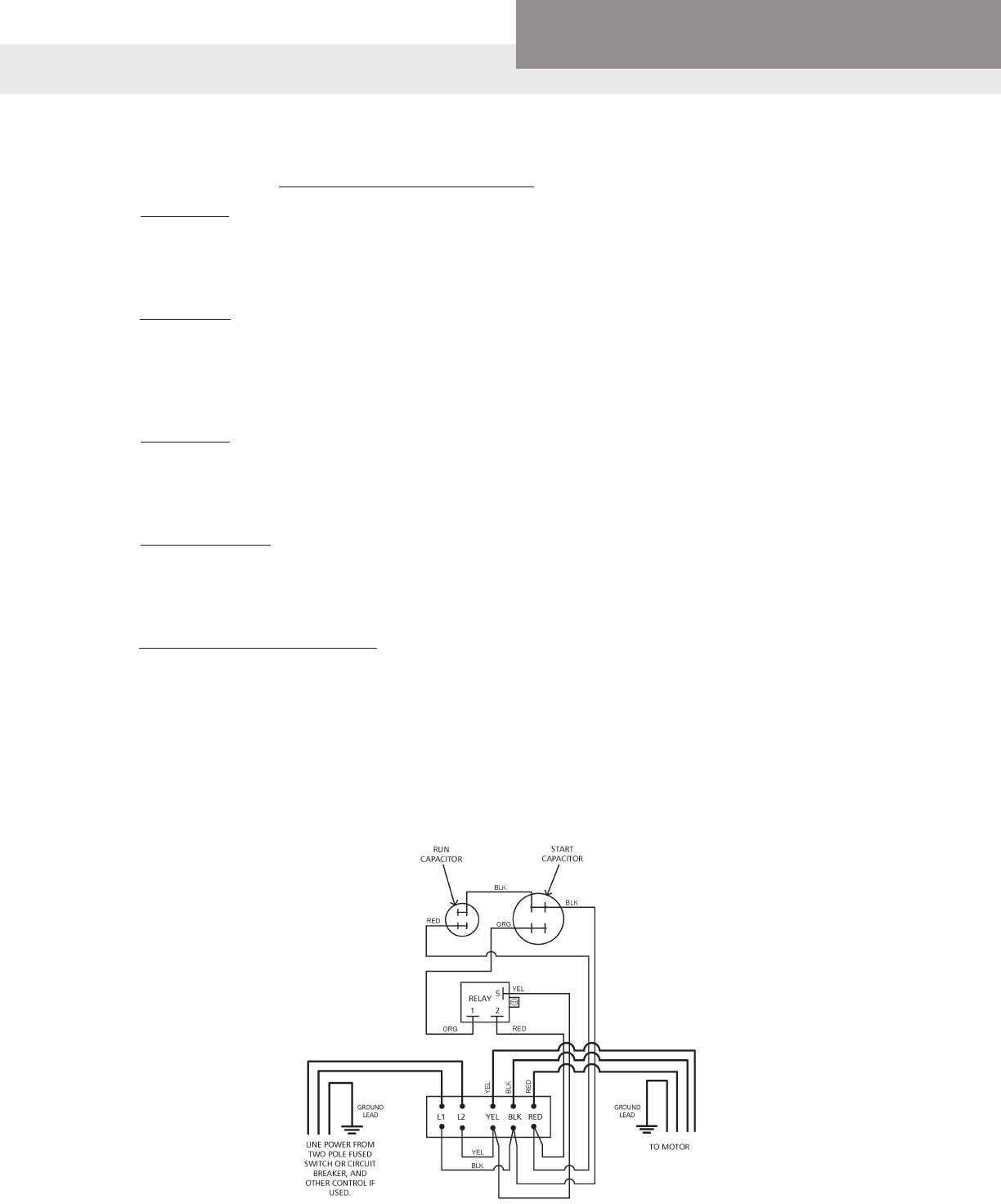
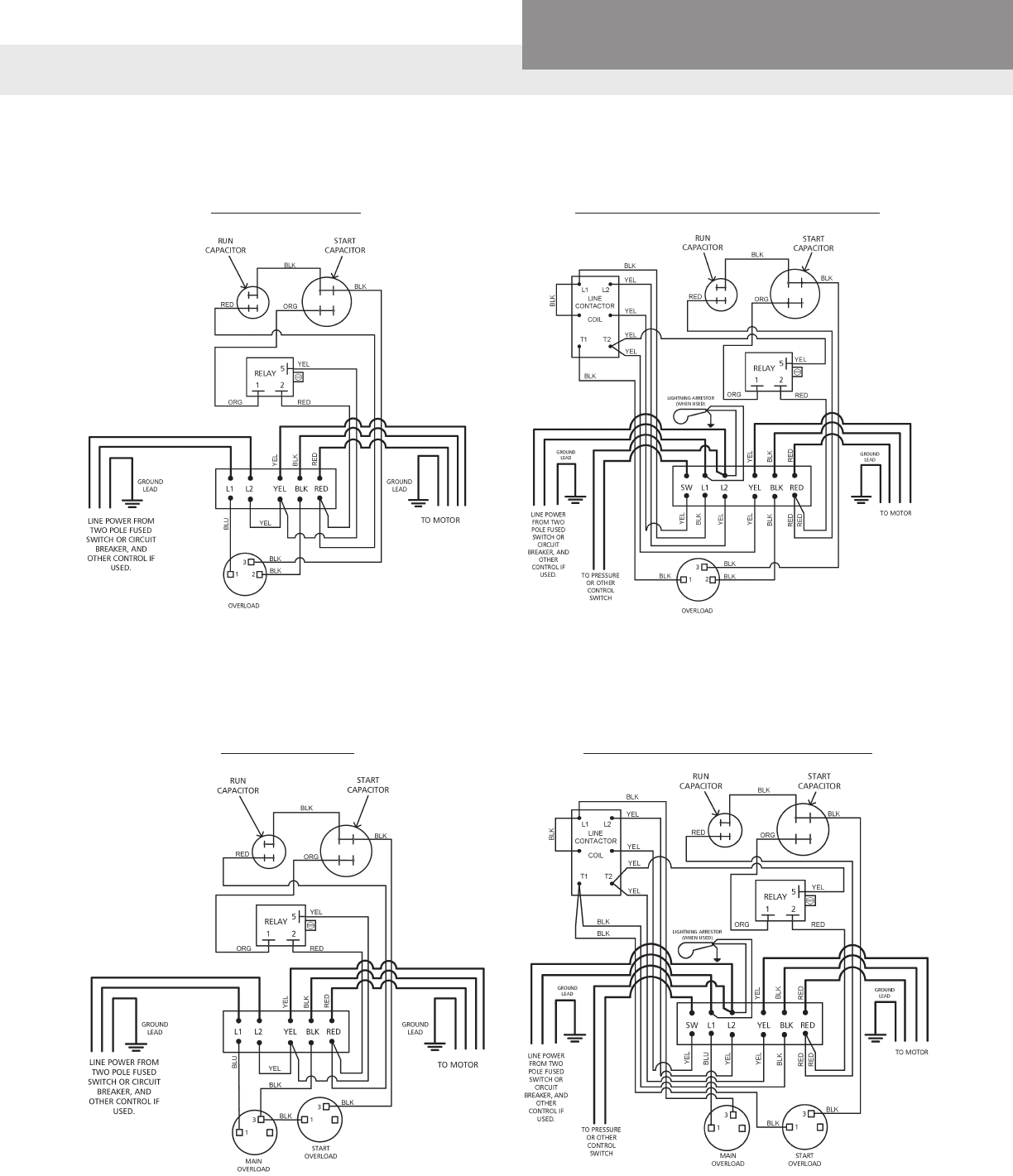
5 AND 7.5 HP WIRING DIAGRAM 10 AND 15 HP WIRING DIAGRAM
CONTROL BOXES FOR 6" CENTRIPRO (HITACHI) SINGLE PHASE MOTORS*
Control Box
Order Number
Use on
Motor
No.
HP Volts
Capacitor Ratings (MFD) Contactor
Rating
Overload
Circuit
Breaker
Enclosure
Dimensions
Shipping
Weight
(lbs.)
Start Caps Run Caps
CB05MC3R 6M051 5
230
189-227uf / 330V 30 / 440V 30A 30A 12.5"H x
11"W x 6.7"D 15
CB07MC3R 6M071 7.5 243 - 292 / 330V 40 / 440V 50A 50A
CB10MC3R 6M101 10 (Qty 2)
161 - 193 / 330V (2) 25 / 440V 75A 60A 17.5"H x
11"W x 6.7"D 27
CB15MC3R 6M151 15 (Qty 2)
216 - 260 / 330V (2) 35 / 440V 90A 90A
CB15MC3R100 ➀100A
PAGE 21
Residential Water Systems
CentriPro
Motor Rating 75º C Insulation - AWG Copper Wire Size
Volts HP 14 12 10 8 6 4 2 1 1/0 2/0 3/0 4/0 250 350 500
230V 5 0 100 170 260 430 680 1060 1330 1660 2070 2560 3190
60 Hz. 7.5 0 0 120 200 310 490 760 940 1150 1420 1740 2120
Single 10 0 0 0 140 220 340 520 660 810 1020 1250 1540
Phase 15 0 0 0 0 140 230 370 450 560 700 870 1080
5 140 230 370 590 920 1430 2190 2690 3290 4030 4850 5870 6650 8460
230V 7.5 0 150 250 410 640 1010 1540 1900 2310 2840 3400 4120 4660 5910 7440
60 Hz. 10 0 0 180 300 470 740 1140 1410 1720 2110 2550 3090 3510 4500 5710
Three 15 0 0 0 200 320 510 790 970 1180 1450 1760 2120 2410 3080 3900
Phase 20 0 0 0 150 240 390 600 750 920 1130 1370 1670 1900 2440 3100
3 Lead 25 0 0 0 0 190 310 490 600 730 900 1100 1330 1510 1950 2480
30 0 0 0 0 0 250 390 490 590 730 890 1080 1230 1580 2030
5 590 950 1500 2360 3700 5750
7.5 410 670 1060 1670 2610 4060 6200 7610
10 300 480 770 1220 1910 2980 4580 5630 6900
15 0 330 530 840 1320 2070 3160 3890 4760 5840 7040
20 0 0 400 640 1020 1600 2460 3020 3710 4560 5500
460V 25 0 0 320 520 810 1280 1960 2410 2960 3640 4400 5350
60 Hz. 30 0 0 0 410 650 1030 1570 1950 2390 2940 3560 4330 4940
Three 40 0 0 0 320 500 790 1220 1500 1840 2270 2730 3320 3760
Phase 50 0 0 0 0 390 610 940 1170 1430 1750 2110 2560 2910 3700 4690
3 Lead 60 0 0 0 0 0 540 830 1020 1250 1540 1860 2250 2550 3260 4120
75 0 0 0 0 0 430 660 820 1000 1230 1480 1810 2050 2640 3360
100 0 0 0 0 0 0 490 610 750 930 1120 1360 1540 1990 2520
125 0 0 0 0 0 0 0 0 620 770 920 1040 1270 1620 2040
150 0 0 0 0 0 0 0 0 0 620 750 910 1040 1330 1680
200 0 0 0 0 0 0 0 0 0 0 610 740 840 1070 1370
Lengths IN BOLD TYPE meet the National Electric Code ampacity only for individual conductor 75º C cable, in free air or water. If other cable
is used, the National Electric Code as well as the local codes should be observed.
NOTE: Since 60º C cable is no longer the industry standard and is not readily available, we have removed the chart.
Use for CentriPro (Hitachi) 6-10" Motors
75º C CABLE, 60 HZ (SERVICE ENTRANCE TO MOTOR) MAXIMUM LENGTH IN FEET
PAGE 22
Residential Water Systems
CentriPro
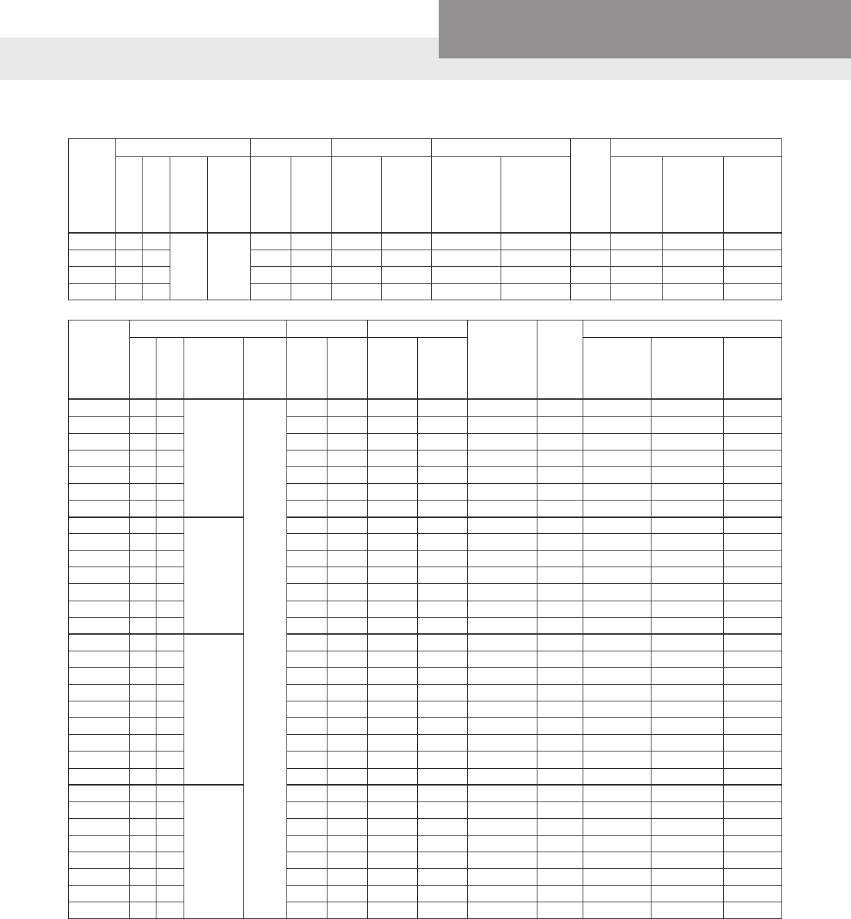
FM-SERIES 6" SUBMERSIBLE MOTORS
Motor
Order
No.
Rating Rated Input Service Factor Full
Load
Speed
(RPM)
Locked
Rotor
Amps
Control
Box
Order No.
HP KW Volts Phase Motor Dia. vs.
Flange Dia.
Service
Factor Amps Watts Amps Watts
6F051 5 3.7
230 1 6" x 6" 1.15
22.8 4975 26.0 5625 3535 104 CB05MC3RF
6F071 7.5 5.5 35.2 7300 40.0 8300 3525 162 CB07MC3RF
6F101 10 7.5 45.7 9700 52.4 11175 3530 202 CB10MC3RF
6F151 15 11 62.4 13725 72.5 15825 3515 296 CB15MC3RF
Motor
Order
No.
Rating Full Load Maximum Load
(SF Load) Full Load
Speed
(RPM)
Locked
Rotor
Amps
HP KW Volts Phase Hz Service
Factor Amps Watts Amps Watts
6F058 5 3.7
200-208
3 6" x 6" 1.15
16.1 4830 18.0 5490 3470 96
6F078 7.5 5.5 23.3 7000 26.8 8070 3435 140
6F108 10 7.5 31.5 9090 35.0 10400 3480 187
6F158 15 11 44.9 13440 50.8 15460 3475 268
6F208 20 15 59.0 17850 67.1 20630 3470 354
6F258 25 19 76.8 22110 86.5 25520 3490 445
6F308 30 22 91.7 26420 103.3 30450 3500 530
6F052 5 3.7
230
14.4 4830 16.1 5490 3460 87
6F072 7.5 5.5 21.5 7000 24.1 8070 3445 127
6F102 10 7.5 28.0 9090 31.5 10400 3470 164
6F152 15 11 40.9 13440 46.3 15460 3470 237
6F202 20 15 53.2 17850 60.8 20630 3460 312
6F252 25 19 66.7 22110 76.0 25520 3480 387
6F302 30 22 79.3 26420 90.2 30450 3480 458
6F054 5 3.7
460
7.0 4830 8.0 5490 3480 44
6F074 7.5 5.5 10.0 7000 11.3 8070 3475 62
6F104 10 7.5 13.1 9090 14.8 10400 3475 82
6F154 15 11 20.4 13440 23.0 15460 3470 117
6F204 20 15 25.8 17850 29.4 20630 3470 151
6F254 25 19 32.8 22110 36.8 25520 3475 187
6F304 30 22 39.3 26420 44.6 30450 3480 226
6F404 40 30 51.3 35030 58.6 40500 3480 302
6F504 50 37 65.8 44350 75.1 51200 3460 385
6F055 5 3.7
575
5.8 4830 6.5 5490 3450 35
6F075 7.5 5.5 8.2 7000 9.3 8070 3470 51
6F105 10 7.5 10.5 9090 11.8 10400 3485 61
6F155 15 11 15.0 13440 17.1 15460 3465 88
6F205 20 15 20.9 17850 23.7 20630 3485 122
6F255 25 19 26.2 22110 29.7 25520 3480 153
6F305 30 22 31.0 26420 35.0 30450 3465 179
6F405 40 30 41.5 35030 47.3 40500 3460 247
Note: FM Sereis motors do not have an adjustable voltage feature. FM Series motors are designed for a specic vlotage and cannot be
changed.
PAGE 23
Residential Water Systems
CentriPro
Motor
Order
No.
Rating Rated Input Service Factor Full
Load
Speed
(RPM)
Locked
Rotor
Amps
Control
Box
Order No.
HP KW Volts Phase Motor Dia. vs.
Flange Dia.
Service
Factor Amps Watts Amps Watts
6F051 5 3.7
230 1 6" x 6" 1.15
22.8 4975 26.0 5625 3535 104 CB05MC3RF
6F071 7.5 5.5 35.2 7300 40.0 8300 3525 162 CB07MC3RF
6F101 10 7.5 45.7 9700 52.4 11175 3530 202 CB10MC3RF
6F151 15 11 62.4 13725 72.5 15825 3515 296 CB15MC3RF
Motor
Order
No.
Rating Full Load Maximum Load
(SF Load) Full Load
Speed
(RPM)
Locked
Rotor
Amps
HP KW Volts Phase Hz Service
Factor Amps Watts Amps Watts
6F058 5 3.7
200-208
3 6" x 6" 1.15
16.1 4830 18.0 5490 3470 96
6F078 7.5 5.5 23.3 7000 26.8 8070 3435 140
6F108 10 7.5 31.5 9090 35.0 10400 3480 187
6F158 15 11 44.9 13440 50.8 15460 3475 268
6F208 20 15 59.0 17850 67.1 20630 3470 354
6F258 25 19 76.8 22110 86.5 25520 3490 445
6F308 30 22 91.7 26420 103.3 30450 3500 530
6F052 5 3.7
230
14.4 4830 16.1 5490 3460 87
6F072 7.5 5.5 21.5 7000 24.1 8070 3445 127
6F102 10 7.5 28.0 9090 31.5 10400 3470 164
6F152 15 11 40.9 13440 46.3 15460 3470 237
6F202 20 15 53.2 17850 60.8 20630 3460 312
6F252 25 19 66.7 22110 76.0 25520 3480 387
6F302 30 22 79.3 26420 90.2 30450 3480 458
6F054 5 3.7
460
7.0 4830 8.0 5490 3480 44
6F074 7.5 5.5 10.0 7000 11.3 8070 3475 62
6F104 10 7.5 13.1 9090 14.8 10400 3475 82
6F154 15 11 20.4 13440 23.0 15460 3470 117
6F204 20 15 25.8 17850 29.4 20630 3470 151
6F254 25 19 32.8 22110 36.8 25520 3475 187
6F304 30 22 39.3 26420 44.6 30450 3480 226
6F404 40 30 51.3 35030 58.6 40500 3480 302
6F504 50 37 65.8 44350 75.1 51200 3460 385
6F055 5 3.7
575
5.8 4830 6.5 5490 3450 35
6F075 7.5 5.5 8.2 7000 9.3 8070 3470 51
6F105 10 7.5 10.5 9090 11.8 10400 3485 61
6F155 15 11 15.0 13440 17.1 15460 3465 88
6F205 20 15 20.9 17850 23.7 20630 3485 122
6F255 25 19 26.2 22110 29.7 25520 3480 153
6F305 30 22 31.0 26420 35.0 30450 3465 179
6F405 40 30 41.5 35030 47.3 40500 3460 247
Note: FM Sereis motors do not have an adjustable voltage feature. FM Series motors are designed for a specic vlotage and cannot be
changed.
FM-SERIES 6" SUBMERSIBLE MOTORS
Motor
Order
No.
Rating Efciency % Power Factor % Winding
KVA
Code
Fuse Sizing Based on NEC
HP kW Volts Phase FL SF FL SF
Main
Resistance
(Black-
Yellow)
Start
Resistance
(Red-
Yellow)
Stan-
dard
Fuse
Dual
Element
Time
Delay
Fuse
Circuit
Breaker
6F051 5 3.7
230 1
74.5 75.5 97.0 97.0 0.27 0.80 E 80 50 70
6F071 7.5 5.5 77.0 77.5 92.0 92.5 0.40 0.85 F 125 80 110
6F101 10 7.5 76.5 76.5 94.0 94.0 0.60 1.89 E 175 90 125
6F151 15 11 81.5 81.5 98.0 98.0 0.25 0.68 E 225 150 200
Motor
Order
No.
Rating Efciency % Power Factor % Line to
Line
Resistance
Ohms
KVA
Code
Fuse Sizing Based on NEC
HP kW Volts Phase FL SF FL SF Standard
Fuse
Dual
Element
Time
Delay Fuse
Circuit
Breaker
6F058 5 3.7
200-208
3
77.5 78.5 86.5 88.0 0.96 H 60 35 50
6F078 7.5 5.5 80.0 80.0 87.5 88.5 0.74 H 90 50 70
6F108 10 7.5 82.5 82.5 86.5 88.0 0.42 H 110 70 100
6F158 15 11 83.5 83.5 87.0 88.5 0.29 H 175 100 125
6F208 20 15 83.0 83.0 87.5 89.0 0.22 H 225 125 175
6F258 25 19 84.0 84.0 85.5 87.5 0.15 H 300 150 200
6F308 30 22 84.5 84.5 86.0 87.5 0.12 H 350 200 250
6F052 5 3.7
230
77.5 78.5 86.5 88.0 1.23 H 60 35 45
6F072 7.5 5.5 80.0 80.0 87.5 88.5 0.82 H 80 45 70
6F102 10 7.5 82.5 82.5 86.5 88.0 0.56 H 100 60 90
6F152 15 11 83.5 83.5 87.0 88.5 0.37 G 150 90 125
6F202 20 15 83.0 83.0 87.5 89.0 0.28 G 200 110 175
6F252 25 19 84.0 84.0 85.5 87.5 0.20 G 225 150 200
6F302 30 22 84.5 84.5 86.0 87.5 0.17 G 300 175 225
6F054 5 3.7
460
77.5 78.5 86.5 88.0 4.93 H 30 15 25
6F074 7.5 5.5 80.0 80.0 87.5 88.5 3.29 H 40 25 35
6F104 10 7.5 82.5 82.5 86.5 88.0 2.15 H 50 30 40
6F154 15 11 83.5 83.5 87.0 88.5 1.30 G 70 45 60
6F204 20 15 83.0 83.0 87.5 89.0 1.04 G 90 50 80
6F254 25 19 84.0 84.0 85.5 87.5 0.77 G 110 70 100
6F304 30 22 84.5 84.5 86.0 87.5 0.65 G 150 80 110
6F404 40 30 85.0 85.0 87.5 89.0 0.51 G 175 100 150
6F504 50 37 84.0 84.0 87.0 88.0 0.39 G 225 150 175
6F055 5 3.7
575
77.5 78.5 86.5 88.0 6.50 H 25 15 20
6F075 7.5 5.5 80.0 80.0 87.5 88.5 4.04 H 30 20 25
6F105 10 7.5 82.5 82.5 86.5 88.0 3.16 G 40 25 30
6F155 15 11 83.5 83.5 87.0 88.5 2.18 G 60 30 45
6F205 20 15 83.0 83.0 87.5 89.0 1.54 G 80 45 60
6F255 25 19 84.0 84.0 85.5 87.5 1.17 G 90 60 80
6F305 30 22 84.5 84.5 86.0 87.5 0.93 G 110 70 90
6F405 40 30 85.0 85.0 87.5 89.0 0.72 G 150 90 125
PAGE 24
Residential Water Systems
CentriPro
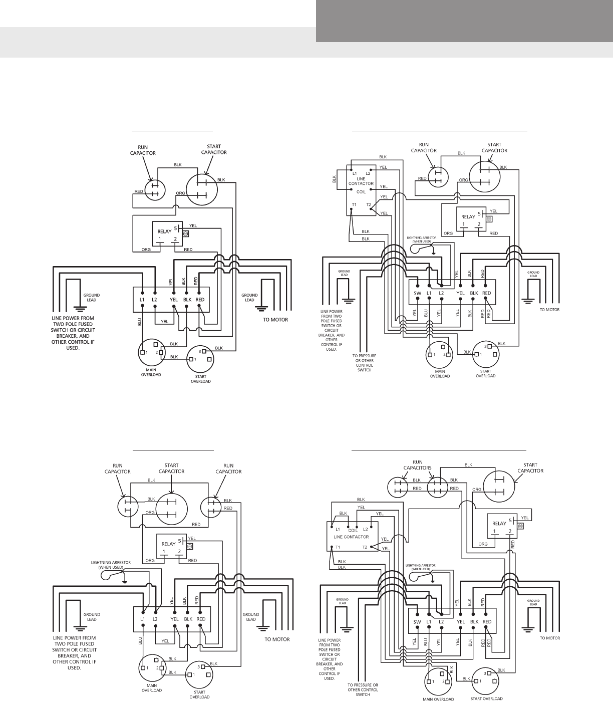
Note: FM Series Control boxes are designed for use with FM Series 6" motors only. Use with motor part numbers "6F…".
➀ Overload circuit breaker is rated at 100 amps versus 90 amp standard in CB15MC. Use in areas with high ambient temperatures to reduce
nuisance tripping.
5 HP WIRING DIAGRAM 7.5, 10 AND 15 HP WIRING DIAGRAM
CONTROL BOXES FOR 6" FM SERIES SINGLE PHASE MOTORS
Control Box
Order Number
Use on
Motor No. HP Volts
Capacitor Ratings
(MFD) Contactor
Rating
Overload
Circuit
Breaker
Enclosure
Dimensions
Shipping
Weight
(lbs.)
Start Caps Run Caps
CB05MC3RF 6F051 5 230 216-260 (2) 30 30A 30A 12.5"H x 11"W
x 6.7"D 15
CB07MC3RF 6F071 7.5 230 (2) 189-227 50A 50A
CB10MC3RF 6F101 10 230
(2) 270-324
(2) 45 70A 70A 17.5"H x 11"W
x 6.7"D 27
CB15MC3RF 6F151 15 230 (2) 70 90A 90A
CB15MC3R100F ➀100A

PAGE 25
Residential Water Systems
CentriPro
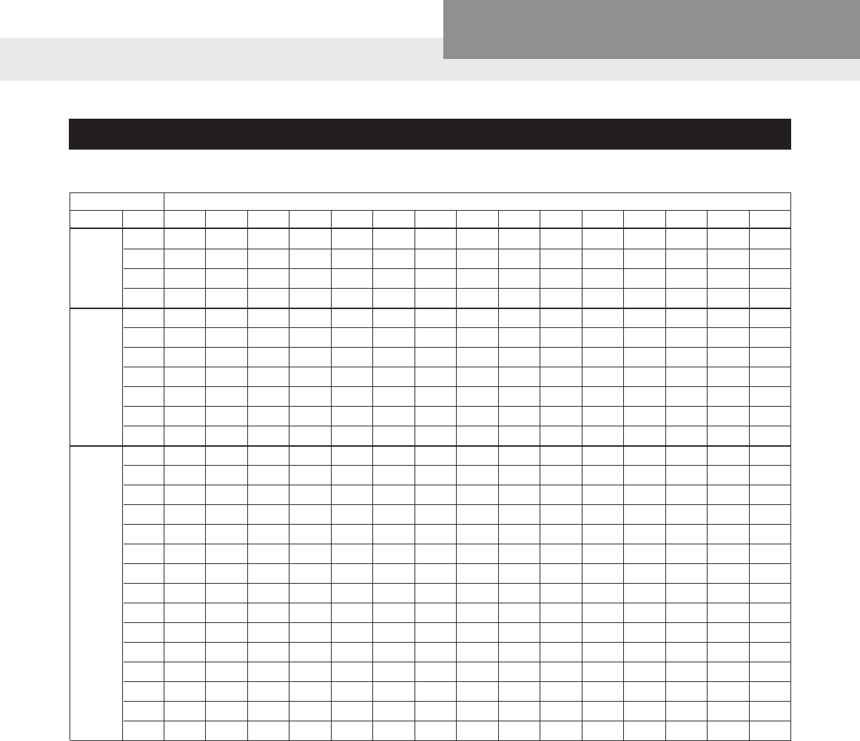
USE FOR CENTRIPRO FM SERIES 6" MOTORS
Three Phase 75º C Cable, 60 Hz (Service Entrance to Motor) Maximum Length in Feet
Motor Rating 75º C Insulation - AWG Copper Wire Size
Volts HP 14 12 10 8 6 4 3 2 1 1/0 2/0 3/0 4/0
230V
60 Hz.
Single
Phase
5 0 0 210 332 517 825 1037 1309 1649 2082 2626 3315 4177
7.5 0 0 0 216 336 536 674 851 1072 1353 1707 2155 2715
10 0 0 0 0 257 409 514 650 818 1033 1303 1645 2073
15 0 0 0 0 0 296 372 469 591 747 942 1189 1498
230 V
60 Hz
Three
Phase
5 134 213 339 537 835 1332 1674 2114 2663 3362 4241
7.5 0 142 226 359 558 890 1118 1412 1779 2246 2833 3577 45063
10 0 0 173 274 427 681 856 10816 1361 1718 2168 2737 3448
15 0 0 0 187 290 463 582 735 926 1169 1475 1862 2346
20 0 0 0 0 221 353 443 560 705 890 1123 1418 1786
25 0 0 0 0 0 282 355 448 564 712 898 1134 1429
30 0 0 0 0 0 0 299 377 475 600 757 956 1204
460 V
60 Hz
Three
Phase
5 538 855 1364 2161 3362
7.5 381 606 966 1530 2380 3794 4770
10 291 462 737 1168 1817 2897 3642 4600
15 0 298 475 752 1169 1864 2344 2960 3728 4706
20 0 0 371 588 915 1458 1833 2315 2917 3682 4645
25 0 0 0 470 731 1165 1465 1850 2330 2941 3711 4685
30 0 0 0 388 603 961 1209 1526 1923 2427 3062 3866
40 0 0 0 0 459 732 920 1161 1463 1847 2331 2942 3707
50 0 0 0 0 0 571 718 906 1142 1441 1818 2296 2892
200-
208 V
60 Hz
Three
Phase
5 108 172 274 434 676 1077 1354 1710 2154 2719 3431 4331
7.5 0 0 184 292 453 723 909 1149 1447 1826 2304 2909 3665
10 0 0 141 223 347 554 696 879 1108 1398 1764 2227 2806
15 0 0 0 0 239 382 480 606 763 964 1216 1535 1933
20 0 0 0 0 0 289 363 459 578 729 920 1162 1464
25 0 0 0 0 0 0 281 356 448 566 714 901 1135
30 0 0 0 0 0 0 0 298 375 473 598 755 951
575 V
60 Hz
Three
Phase
5 827 1316 2099 3324
7.5 578 920 1467 2323 3615
10 456 725 1156 1831 2849 4542
15 314 500 798 1264 1966 3134 3940
20 0 361 576 912 1419 2261 2843 3590 4523
25 0 0 459 728 1132 1805 2269 2865 3609 4559
30 0 0 390 617 961 1531 1925 2431 3063 3866
40 0 0 0 457 711 1133 1424 1799 2266 2861 3609 4556
PAGE 26
Residential Water Systems
CentriPro
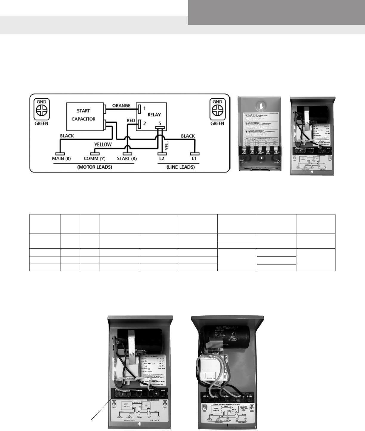
1Ø THREE-WIRE CONTROL BOX WIRING CHARTS
Quick Disconnect ½ – 1 HP
WIRING DIAGRAM
“K” REPAIR PARTS FOR QUICK DISCONNECT STYLE CONTROL BOXES
Order Capacitor Start Capacitor
Start Relay Standard Relay (Ohms)
Number HP Volts Order Capacitor Voltage / Order No. Circuit Breaker #2-#5
Number Mfd Quantity
CB05411 .5 115 9K450 250 - 300 125 / 1 ➀ 9K457 30 700 – 1800
➁ 9K566
CB05412 .5 230 9K448 59 - 71 250 / 1 ➀ 9K462 15
CB07412 .75 230 9K449 86 - 103 250 / 1 ➁ 9K567 20 4500 – 7000
CB10412 1 230 9K447 105 - 126 250 / 1 25
➀ First Design - Up to June 2009 - Relay tab on bottom, capacitor held by bracket and screw. See pictures below. 208 V use 9K461 relay.
➁ Current Design - Starting June 2009 - Relay tab on top and capacitors, all held by one screw. See pictures below. The relays are designed
for operation in a specic orientation, therefore there are two different numbers now. 208 V use 9K568 relay.
First Design
Tab Down ➀
Current Design
Tab Up ➁
PAGE 27
Residential Water Systems
CentriPro
CENTRIPRO QUICK DISCONNECT WITH PUMPSAVER INSIDER
CONNECTIONS:
1. Remove the cover from the front of the 3-wire CentriPro control box.
2. Remove the yellow wire from the terminal strip at L2.
3. Remove the black wire connecting L1 and the capacitor completely from the box.
4. Press the PumpSaver® onto the L1 and L2 terminals.
5. Reconnect the yellow wire to L2 on the PumpSaver.
6. Connect the blue wire attached to the PumpSaver to the dual-lug terminal (with the black wire) of the
capacitor.
ORANGE
BLUE
BLK VOLTAGE
RELAY
1
2
5
YEL
YEL
RED
B(MAIN) Y(COMM) R(START) L2 L1
MODEL 111/231
INSIDER
CENTRIPRO CONTROL BOX WITH INSIDER INSTALLED
PAGE 28
Residential Water Systems
CentriPro
CENTRIPRO QUICK DISCONNECT WITH QD PUMPTEC
CONNECTIONS:
1. Remove the cover from the front of the 3-wire CentriPro control box.
2. Remove the yellow wire from the terminal strip at L2.
3. Remove the black wire connecting L1 and the capacitor from L1.
4. Press the QD Pumptec onto the L1 and L2 terminals.
5. Reconnect the yellow wire to L2 on the QD Pumptec.
6. Connect the black wire from the capacitor to L1 on the QD Pumptec.
ORANGE
BLACK
BLK VOLTAGE
RELAY
1
2
5
YEL
YEL
RED
B(MAIN) Y(COMM) R(START) L2 L1
QD
PUMPTEC
L1
L2
CENTRIPRO CONTROL BOX WITH PUMPTEC INSTALLED
PAGE 29
Residential Water Systems
CentriPro
CSCR 1Ø CONTROL BOXES CAPACITOR START - CAPACITOR RUN
Control
Box Order
Number
HP Volts
Old Control
Box Order
Number
Capacitor
Repair Part
Number
Capacitor
Mfd.
Capacitor
Type
Capacitor
Voltage
Capacitor
Quantity
Overload
Order
Number ②
Start Relay
Order
Number ①
CB05412CR .5
230
—9K465 43-53 Start 250
1
N/A 9K458
9K466 15 Run 370
CB07412CR .75 — 9K448 59-71 Start 250 N/A 9K458
9K467 23 Run 370
CB10412CR 1 — 9K449 86-103 Start 250 N/A 9K458
9K467 23 Run 370
CB15412CR 1.5 00074 9K447 105-126 Start 250 9K471 9K458
9K466 15 Run 370
CB20412CR 2 00084 9K447 105-126 Start 250 9K481 9K458
9K451 20 Run 370
CB30412CR 3 00094 9K453 208-250 Start 250 9K482
9K459
9K454 45 Run 370
CB50412CR 5 00104 9K455 270-324 Start 330 9K483
9K456 40 Run 370 2
➀ If supply voltage is between 200V-210V a 208V start relay, order no. 9K479, is required.
➁ Overload for 2, 3, and 5 HP CSCR boxes are sold prewired and soldered as an assembly. No eld soldering or wiring required.
“K” REPAIR PARTS
FOR USE WITH 3 WIRE, 1Ø, 4" CENTRIPRO MOTORS
Control Box
Order
Number
HP KW Volts
May
Replace
GP #
May Replace RJ #
Standard
Circuit
Breaker
Standard
Fuse
Dual Element
Time Delay
Fuse
Enclosure
Dimensions
W x D x H (in)
Shipping
Wt. (lbs)
CB05412CR 0.5 .37
230
—50F311CB
S50N1CB, A50N1CB 10 15
10
8.1 x 5.9 x 9.3
7
CB07412CR .75 .55 — 75F311CB
S75N1CB, A75N1CB 15 20
CB10412CR 1 .75 — S100F311CB
S100N1CB, A100N1CB
CB15412CR 1.5 1.1 00074 150F311CB
S150N1CB, A150N1CB 25 30
15
CB20412CR 2 1.5 00084 200F311CB
S200N1CB, AS200T1CB 20
CB30412CR 3 2.2 00094 300F311CB
S300N1CB 40 45 25
CB50412CR 5 3.7 00104 500F311CB
S500N1CB 60 80 45 8

PAGE 30
Residential Water Systems
CentriPro
MAGNETIC CONTACTOR (MC) CONTROL BOXES
FOR USE WITH 3 WIRE, 1Ø, 4" CENTRIPRO MOTORS AND 4" (6", 5 HP) FRANKLIN ELECTRIC MOTORS
Control Box
Replaces Replaces MayReplace Standard Standard Dual Element Enclosure Shipping
Order Number HP KW Volts GP # RJ # FE # Circuit Fuse Time Delay Dimensions Wt. (lbs)
Breaker Fuse W x D x H (in)
CB15412MC 1.5 1.1 230 No Equal No Equal No Equal 30 35 20
CB20412MC 2 1.5 230 00084MC No Equal 2823018310 25 30 20 8.1 x 5.9 x 9.3 8
CB30412MC 3 2.2 230 00094MC S300N1CBC 2823028310 40 45 30
CB50412MC 5 3.7 230 00104MC S500N1CBC 2821139310 60 80 45 11 x 6.7 x 12.5 15
“K” REPAIR PARTS
Control Box Capacitor
Capacitor Capacitor Capacitor Capacitor Contactor Overload Start Relay
Order Number HP KW Volts Repair Part Type Mfd. Voltage Quantity Order Order Order
Number Number Number Number
CB15412MC 1.5 1.1 9K447 Start 105-126 250 9K493
9K466 Run 15 370 9K458
CB20412MC 2 1.5 9K447 Start 105-126 250 1 9K485 9K480 (S)
230 9K451 Run 20 370 9K472 (M)
CB30412MC 3 2.2 9K453 Start 208-250 250 9K473 (S)
9K454 Run 45 370 9K474 (M) 9K459
CB50412MC 5 3.7 9K455 Start 270-324 330 1 9K486 9K475 (S)
9K456 Run 40 370 2 9K476 (M)
Repair parts above are compatible with and replace parts in old Goulds Water Technology or Franklin Electric control boxes.
Order Number 9K479 for 200/208 Volt Start Relay.
PAGE 31
Residential Water Systems
CentriPro
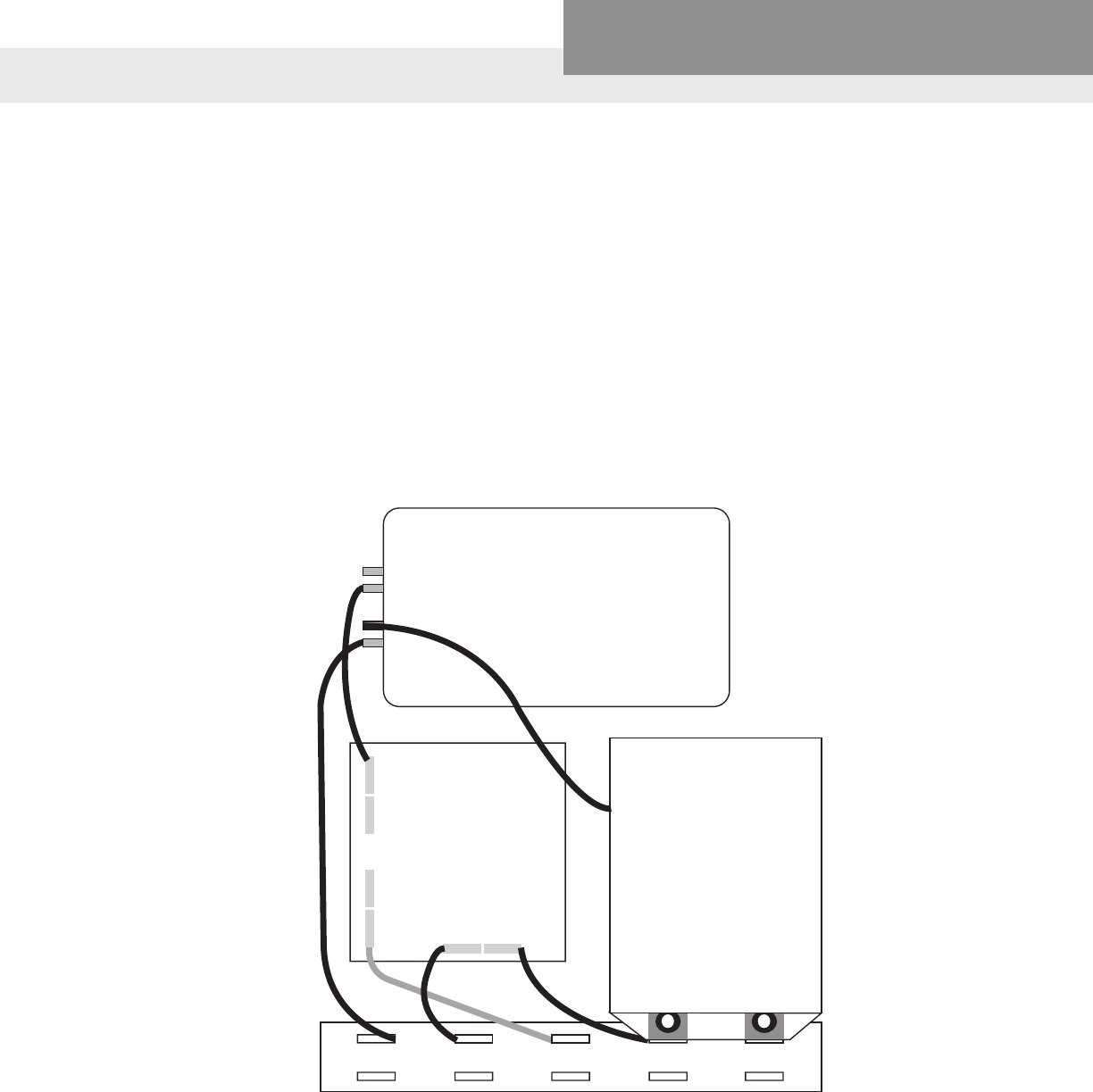
½, ¾ AND 1 HP – 1Ø CSCR CONTROL BOX WIRING DIAGRAMS
CSCR AND MC CONTROL BOX CHECK OUT
CHECKING PROCEDURE: BE SURE POWER IS TURNED OFF.
A. OVERLOAD (PUSH RESET BUTTONS TO MAKE SURE CONTACTS ARE CLOSED.)
1. OHMMETER SETTING: (R X 1)
2. TERMINAL CONNECTIONS: OHMMETER LEADS TO OVERLOAD TERMINALS.
3. OHMMETER READING: SHOULD NOT BE OVER 0.5 OHMS.
B. CAPACITOR (DISCONNECT ONE LEAD FROM EACH CAPACITOR PRIOR TO CHECKING.)
1. OHMMETER SETTING: (R X 1000).
2. TERMINAL CONNECTIONS: INDIVIDUAL CAPACITOR TERMINALS.
3. OHMMETER READING: POINTER SHOULD SWING TOWARD ZERO THEN DRIFT BACK TOWARD
INFINITY.
C. RELAY COIL (DISCONNECT LEAD FROM TERMINAL 5)
1. OHMMETER SETTING: (R X 1000).
2. TERMINAL CONNECTIONS: “5” AND “2” ON RELAY.
3. OHMMETER READING: 4500-7000 OHMS.
D. RELAY CONTACT (DISCONNECT LEAD FROM TERMINAL 1)
1. OHMMETER SETTING: (R X 1).
2. TERMINAL CONNECTIONS; “1” AND “2” ON RELAY.
3. OHMMETER READING: SHOULD BE ZERO.
E. MAGNETIC CONTACTOR ONLY (DISCONNECT 1 COIL LEAD)
1. OHMMETER SETTING: (R X 100).
2. CHECK COIL RESISTANCE: 180-1400 OHMS.
3. REMOVE CONTACT COVER AND INSPECT CONTACTS.
PAGE 32
Residential Water Systems
CentriPro
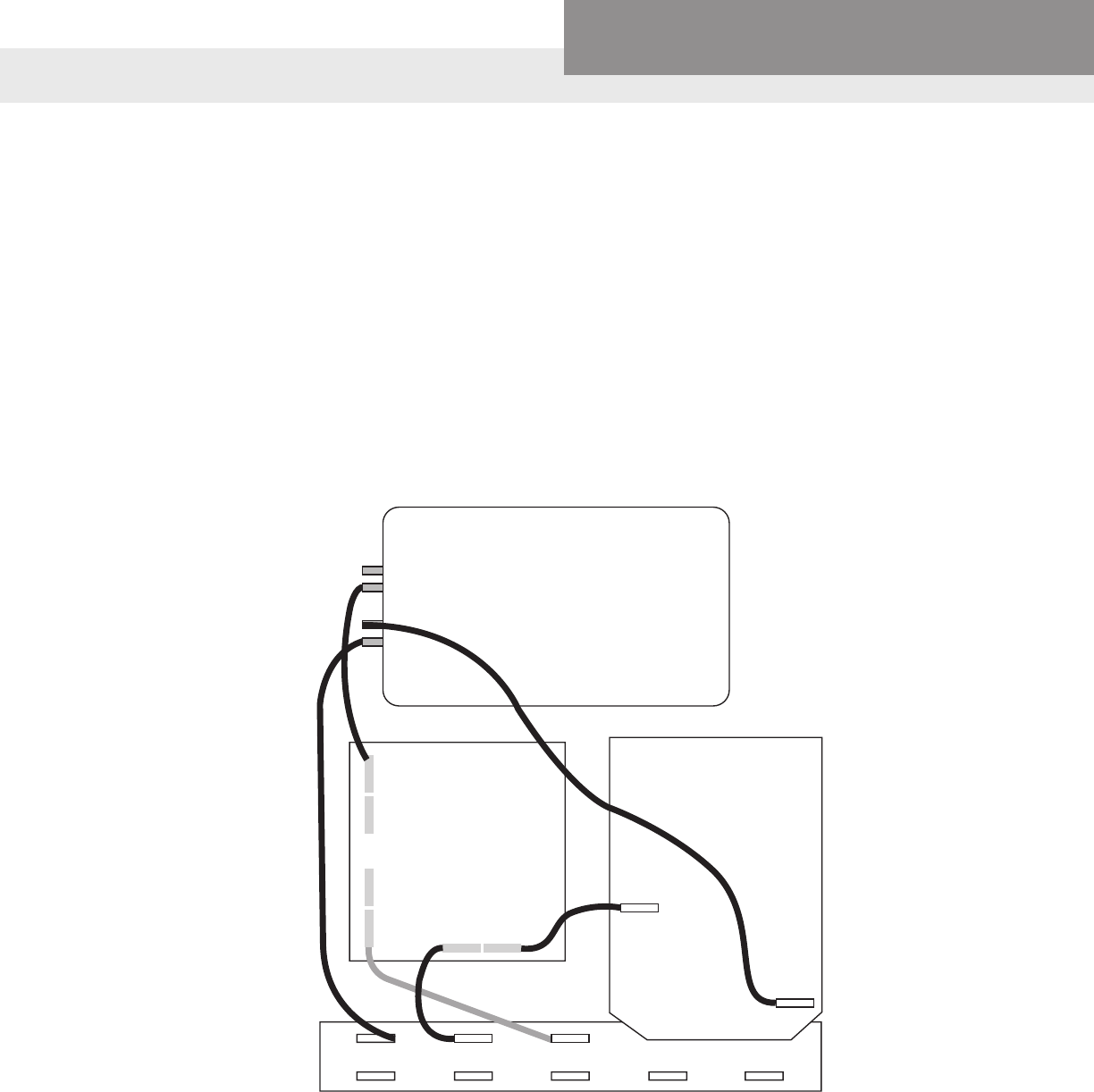
1Ø CONTROL BOX WIRING DIAGRAMS
1½ HP STANDARD 1½ HP WITH MAGNETIC CONTACTOR
2 HP STANDARD 2 HP WITH MAGNETIC CONTACTOR
PAGE 33
Residential Water Systems
CentriPro
1Ø CONTROL BOX WIRING DIAGRAMS
3 HP STANDARD 3 HP WITH MAGNETIC CONTACTOR
5 HP STANDARD 5 HP WITH MAGNETIC CONTACTOR
PAGE 34
Residential Water Systems
CentriPro
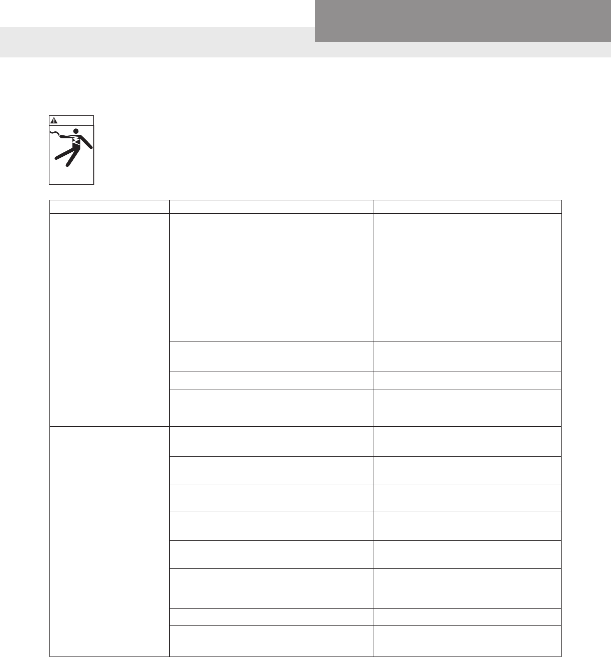
PUMP TROUBLESHOOTING
WARNING
Hazardous voltage
can shock, burn or
cause death.
DISCONNECT AND LOCKOUT ELECTRICAL POWER BEFORE ATTEMPTING ANY SERVICE.
FAILURE TO DO SO CAN CAUSE SHOCK, BURNS OR DEATH.
Symptom Probable Cause Recommended Action
PUMP MOTOR
NOT RUNNING
LITTLE OR
NO LIQUID
DELIVERED
BY PUMP
1. Motor thermal protector tripped
a. Incorrect control box
b. Incorrect or faulty electrical connec-
tions
c. Faulty thermal protector
d. Low voltage
e. Ambient temperature of control box/
starter too high
f. Pump bound by foreign matter
g. Inadequate submergence
2. Open circuit breaker or blown fuse
3. Power source inadequate for load
4. Power cable insulation damage
5. Faulty power cable splice
1. Allow motor to cool, thermal
protector will automatically reset
a – e. Have a qualied electrician inspect
and repair, as required
f. Pull pump, clean, adjust set depth as
required
g. Conrm adequate unit submergence in
pumpage
2. Have a qualied electrician inspect and
repair, as required
3. Check supply or generator capacity
4 – 5. Have a qualied electrician inspect and
repair, as required
1. Faulty or incorrectly installed
check valve
2. Pump air bound
3. Lift too high for pump
4. Pump bound by foreign matter
5. Pump not fully submerged
6. Well contains excessive amounts
of air or gases
7. Excessive pump wear
8. Incorrect motor rotation – three phase only.
1. Inspect check valve, repair as required
2. Successively start and stop pump until ow
is delivered
3. Review unit performance, check with dealer
4. Pull pump, clean, adjust set depth as
required
5. Check well recovery, lower pump if possible
6. If successive starts and stops does not
remedy, well contains excessive air or gases
7. Pull pump and repair as required
8. Reverse any two motor electrical leads
PAGE 35
Residential Water Systems
CentriPro
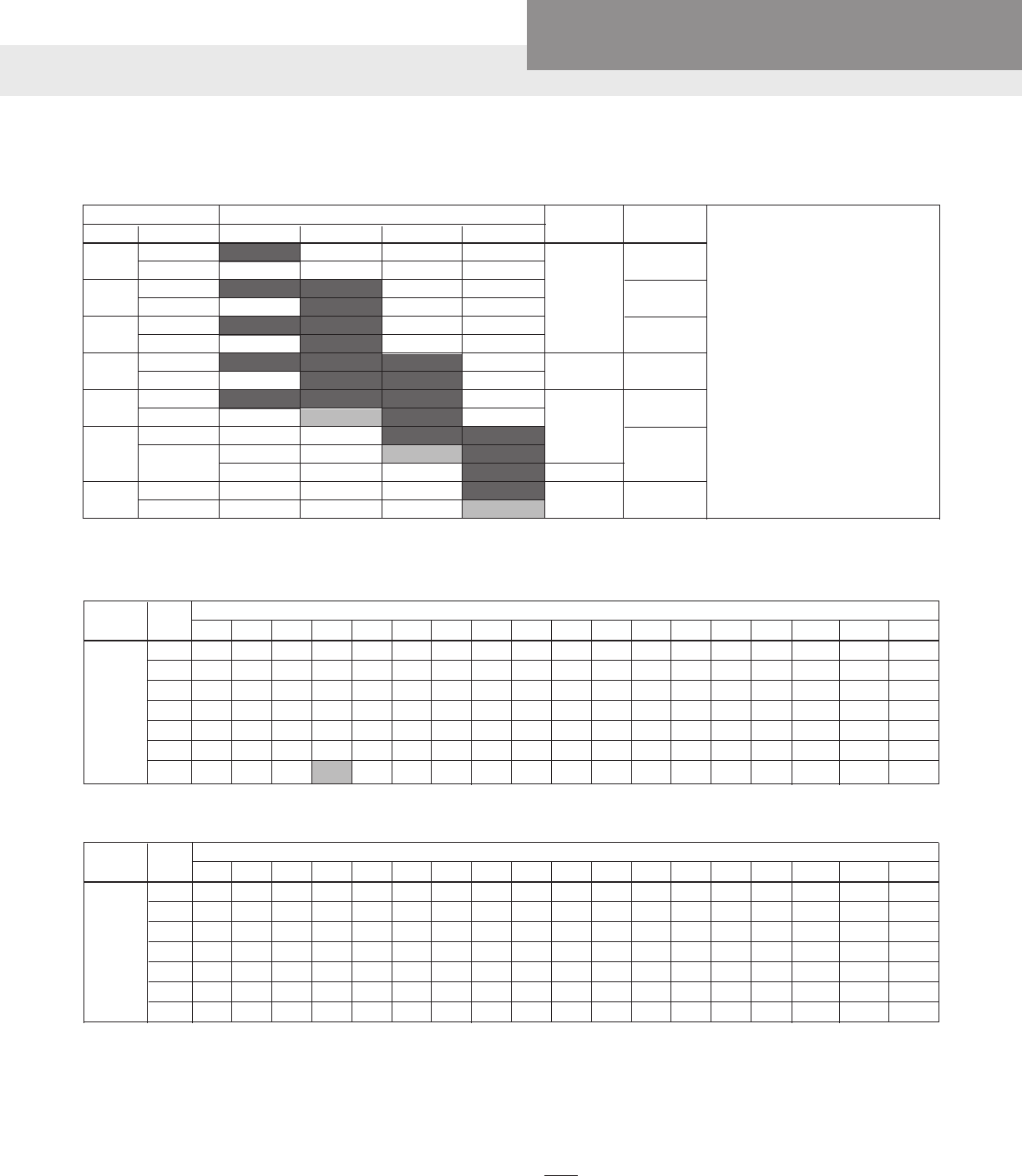
AQUAVAR SOLO2 DATA
Service Entrance to Controller
Controller Motor Copper Wire Size 75ºC Insulation Exposed to a Maximum of 50ºC (122ºF) Ambient Temperature ⑥
Input HP 14 12 10 8 6 4 3 2 1 1/0 2/0 3/0 4/0 250 300 350 400 500
½ 366 583 925 1336 2107 3345 4175 5267 6637 8364
¾ 279 445 706 1020 1608 2552 3186 4019 5065 6383 8055
1 226 360 571 824 1300 2064 2576 3250 4095 5161 6513 8201
1½ * 286 455 657 1036 1644 2052 2589 3262 4111 5188 6533 8236 9710
2 * * 331 478 754 1197 1495 1886 2376 2995 3779 4759 5999 7073 8455 9852
3 * * 246 355 561 890 1111 1401 1766 2225 2808 3536 4458 5256 6283 7321 8343
5 * * * 218 343 545 680 858 1081 1363 1720 2165 2730 3219 3847 4483 5109 6348
230V
1 PH
Controller to Motor
Controller Motor Copper Wire Size 75ºC Insulation Exposed to a Maximum of 50ºC (122ºF) Ambient Temperature ⑥
Output HP 14 12 10 8 6 4 3 2 1 1/0 2/0 3/0 4/0 250 300 350 400 500
½ 905 1442 2290 3306 5213 8276
¾ 690 1100 1748 2523 3978 6316 7884 9945
1 558 890 1413 2040 3216 5106 6375 8041
1½ 445 709 1126 1625 2562 4068 5078 6406 8072
2 324 516 820 1184 1866 2963 3699 4666 5879 7410 9351
3 241 384 609 880 1387 2202 2749 3467 4369 5506 6949 8750
5 * 235 373 539 849 1348 1683 2123 2675 3372 4255 5358 6755 7964 9520
⑤ Reduce lengths by 13% for 200 V systems. ⑥ Lengths in bold require 90ºC wire. Shading indicates 40º C maximum ambient. * Wire does not meet the N.E.C. ampacity requirement.
230V
3 PH
The lengths in each of the Wire Sizing tables represent 100% of the allowable voltage drop when motor is running at full load.
When sizing wire, the voltage drop of each wire segment must be included. The total must not exceed 100% of the allow-
able drop. Take for example a 1.5 HP motor with a distance from Service Entrance to Controller of 100' and 500' between the
Controller and Motor.
• Service Entrance to Controller = 100' of 10 AWG (100/455) = 22 % (455' is from the S.E. to Controller chart)
• Controller to Motor = 500' of 12 AWG (500/709) = 71 % (709' is from the Controller to Motor chart)
Total Drop (must be ≤ 100%) 93 %
If the distance from the Controller to Motor was 600' (600/709) = 85% + 22% = 107%, we would need to use #10 wire for that
segment, ex. 600/1126 = 53% + 22% (for 100' of #10) = 75% which is acceptable. It is also acceptable to use different wire
sizes for the Buried and Well sections of wire.
WIRE SIZING – MAXIMUM CABLE LENGTHS IN FEET TO LIMIT VOLTAGE DROP TO 5% FOR 230 V SYSTEMS ⑤
CONTROLLER, BREAKER, GENERATOR SIZING
Motor Controller Model ➁ Circuit Generator ➃
HP Voltage ➀ 1AS15 3AS20 3AS30 3AS50 Breaker ➂ (VA)
½ 230
2200
200
¾ 230 15 2900
200
1 230
3500
200
1½ 230 20 4400
200
2 230
6100
200 30
230
3 200 8100
40
5 230 50 13300
200
➀ Supply voltage must be 196 VAC – 265
VAC.
➁ Shaded areas indicate which controller
models can be used with which motors.
Lighter shading indicates combina-
tions where controller will limit peak
performance to 85% of catalog value for
pump/motor.
➂ Circuit Breaker or Dual Element Time Delay
Fuse Size (Amps) protecting branch circuit
supplying controller.
➃ Minimum size of single phase 240 V
generator required.

PAGE 36
Residential Water Systems
CentriPro
SERVICE FACTOR AMPS ALL MOTORS
AQUAVAR SOLO2 AND BALANCED FLOW REPAIR PARTS
(See Ecom website or PRP, Repair Part Price Book, for Current Prices)
Order Number Description
6K210 Gauge Guard - Transducer Protector
9K518 100 PSI Transducer 0.5 – 4.5V
9K519 200 PSI Transducer 0.5 – 4.5V
9K520 300 PSI Transducer 0.5 – 4.5V
9K523 10 Bar Transducer 0.5 – 4.5V (145 PSI)
9K524 SOLO and Balanced Flow Screw Repair Kit
9K525 SOLO and Balanced Flow Fan Repair Kit
9K545 10' Transducer Cable with Ground and GRN. Clamp
9K546 15' Transducer Cable with Ground and GRN. Clamp
9K547 25' Transducer Cable with Ground and GRN. Clamp
9K548 50' Transducer Cable with Ground and GRN. Clamp
9K549 100' Transducer Cable with Ground and GRN. Clamp
9K576 150' Transducer Cable with Ground and GRN. Clamp
9K577 200' Transducer Cable with Ground and GRN. Clamp
9K550 AquaBoost UIB
9K552 Balanced Flow and Aquavar SOLO UIB
9K575 Balanced Flow and Aquavar SOLO (all sizes) R05 Programmer
9K585 Water Sensor with Relay Contact
9K589 Over-Pressure Switch, 60-120 PSI, Balanced Flow or S-Drive
230 Volt 200 Volt
HP 1Ø 2-Wire 1Ø 3-Wire 3Ø 3Ø
CentriPro1 Franklin Grundfos CentriPro Franklin Grundfos CentriPro Franklin Grundfos CentriPro Franklin
½ 4.7/4.7 6 6 6.3 6 6 N/A N/A N/A N/A N/A
¾ 6.4/6.2 8 8.4 8.3 8 8.4 3.9 3.8 N/A 4.5 4.4
1 9.1/8.1 9.8 9.8 9.7 9.8 9.8 4.7 4.7 N/A 5.5 5.4
1½ 11.0/10.4 13.12 13.12 11.1 11.5 11.6 6.1 5.9 7.3 7.2 6.8
2 N/A N/A N/A 12.2 13.22 13.22 7.6 8.1 8.7 8.8 9.3
3 N/A N/A N/A N/A N/A N/A 10.1 10.9 12.2 12 12.5
5 N/A N/A N/A N/A N/A N/A 17.5 17.8 19.82 20.22 20.52
1. CentriPro 2-Wire motors have Generation 1 and Generation 2 amp ratings, see motor nameplate or motor data sticker that was supplied with motor.
2. Amps are higher than controller overload range - use of these motors will current limit and provide reduced performance.

PAGE 37
Residential Water Systems
CentriPro
THREE PHASE MOTOR OPERATION ON VFD'S
Variable Frequency Drive’s (VFD) can be used with the 3 phase CentriPro motor provided the operator
meets the following criteria:
1) Maintain frequencies from 30HZ – 60HZ. Do not operate below 30HZ for more than 1 second. 80 HZ
operation can be used.
2) Ensure VFD is a PWM, IGBT, Volts per Hz scalar type and does not produce more than 500 volts dV/dT.
3) Use a load reactor (load lter) of 3% impedance or more on motor lead lengths of 50 wire feet or more. The
Balanced Flow product already includes this in all models.
4) Follow all NEC, state, local or provincial electrical codes for Power Conversion Equipment wiring and
installation.
5) Provide appropriate dedicated short circuit protection. Properly sized fuses or breaker disconnects.
6) Size wire according to NEC, state, local or provincial codes OR refer to manufacturers recommendation for
wiring sizing.
7) Ensure proper ow around motor.
8) Maintain proper grounding of the motor back to drive and service entrance. Common ground throughout
system!
The following are some installation issues we have seen on returned Balanced Flow controllers which
factory re-testing has shown to operate perfectly:
Symptom Cause
• Cycling, won't turn off, poor pressure control Incorrect tank pre-charge pressure
• Cycling and wide pressure swings Larger than recommended tank
• Poor performance Motor running backwards
Performance Improvement Suggestions:
• Installing a spring check valve on the pump side of the tank can reduce time to standby when ow stops.
• Poor pressure control can be caused by a clogged sensor. Not an issue for sensors 4/09 and later.
• Updating controllers built prior to 4/09 with latest Software, UIB and Sensor will improve reliability and
performance.
• Updating software in controllers built after 4/09 may improve performance.
• Many generators produce voltages that exceed the 264VAC max rating of the controller. Test the generator
output voltage when no load is connected. If the voltage exceeds 264VAC, do not use it with the BF
controller!
PAGE 38
Residential Water Systems
CentriPro
AQUAVAR SOLO2 TROUBLESHOOTING
The Status Indicator and Parameter Display are visible through the cover lable to indicate the system status,
i.e. running, stopped or faulted. When faulted, the status indicator light will be Red and the Parameter Display
will show the error code in the format F00 where "F" indicates fault and "00" will be the fault code number. The
Status Indicator will ash the error code as the number of ashes followed by a 1 second pause. The number of
ashes can be from 2 to 9. The error code will be repeated until the fault is cleared. The following describes state
of the Status Indicator and Parameter Display duing various conditions and faults:
NO LIGHT
Parameter
Display
Status
Indicator Controller Status Description
No Light No Light Low/No Input Voltage Check the input voltage to the controller. Measure the
voltage between L1 and L2 using an AC Voltmeter. This
voltage should be greater than 190Vac.
PrOG No Light Program Mode The controller is set to programming mode when the
Programming Position (located in the upper-left corner of the
UIB) pins are connected together at power up. To remove
the controller from Program Mode, remove the jumper/
connection connecting the Programming Position pins, turn
off power to the controller, wait 1 minute, turn on power to
the controller.
GREEN LIGHT CODES
Parameter
Display
Status
Indicator Controller Status Description
Various Constant
Green
Standby/Low Voltage
Constant Green Light indicates the pump is in Standby mode
with the pump stopped. The system is in Standby mode when
there is no ow in the system and the pressure setting has
been reached.
It is also possible the system is in a Low Voltage condition
where the line input voltage is between 85-190VAC.
StOP Constant
Green
Pump Stopped
A Constant Green Status Indicator along with a StOP message
on the Parameter Display indicates that the Run/Stop input is
open which forces the pump to stop.
Check the device controlling the Run/Stop Input for proper
operation. Verify the input is wired correctly. The Run/Stop
Input wiring must never be installed in the same conduit as
power wiring and there must be a minimum of 12" between
the Run/Stop Input wiring and the power wires.
Various Blinking
Green
Pump Running
Flashing Green Light indicates the pump is running.
RED LIGHT CODES
Parameter
Display
Fault Code
Flashes Controller Status
Description
This information is to be used by professional installers or
qualied personnel only.
F01 Constant
Red
Controller Error
Internal controller fault. To clear the fault, turn off power to
the controller, wait 1 minute, turn on power to the controller.
If fault persists Replace controller.
To clear fault perform
a System Reset,
or turn off power
to controller, wait
1 minute, turn on
power to controller. If
fault persists contact
installer.
PAGE 39
Residential Water Systems
CentriPro
AQUAVAR SOLO2 TROUBLESHOOTING
FAULT BLINK CODES (continued)
RED LIGHT CODES
Parameter
Display
Fault Code
Flashes Controller Status
Description
This information is to be used by professional installers or
qualied personnel only.
F02 2 Blinks Dry Well
No Water/Loss of
Prime
This fault can be caused by:
• Water supply level in well falls below suction inlet of pump.
• Plugged suction screen.
• Restriction in pipe between pump and pressure sensor.
• Air bound pump – see “Purging System”
• Incorrect setting of “MAXIMUM SPEED” switch. Be sure to
set the “MAXIMUM SPEED” switch to 80 Hz when using
mismatched pumps (water ends) and motors.
• Incorrect setting of “MOTOR OVERLOAD SETTING (SFA)”
switch. Ensure the Motor Overload Setting (SFA) Switch is
not set higher than the Service Factor Amps (SFA) listed on
the motor nameplate.
Refer to the dSEt menu for details on conguring the Dry
Well Function. The controller may automatically restart if
Progressive (ProG) or Fixed Time (Ft) restart is selected.
If nuisance tripping continues after adequate water supply
has been veried:
• Set the Dry Well Sensitivity switch to LOW
• Measure the maximum possible output current for the
system. Set the MOTOR OVERLOAD Setting according to
this value instead of motor SFA.
• Turn the Dry Well Function off by selecting OFF in the dSEt
parameter group in the Advanced Menu.
Dry Well can be reset by pressing both pushbuttons at the
same time or by turning off the power to the controller.
The Dry Well Function
is congured using
the dSEt parameter
group in the
Advanced Menu. If
fault persists contact
installer.
F03 3 Blinks Sensor Fault This fault can be caused by:
• Disconnected sensor. Disconnect sensor from sensor cable
connector and reconnect to ensure a good connection.
• Disconnected sensor cable lead inside the controller. Check
for loose wires where the sensor cable connects to the
circuit board by tugging on each wire.
• Broken wire in the sensor cable.
• Miswired sensor cable. Check that the wires are connected
to the correct terminals on the sensor connector. The
correct location of the wires is indicated on the circuit
board. B=Black, R=Red, W=White, G=Green.
• Failed sensor. With the sensor cable connected to the
circuit board, measure the DC voltage between the black
and white wires of the sensor cable at the sensor connector.
The voltage measured should be between 0.5Vdc and
4.5Vdc depending on the system pressure, see chart below.
• A vacuum on the sensor (transducer) of 17" Hg or more will
cause a sensor fault, eliminate the vacuum.
NOTE: Ensure the Transducer Jumper is properly placed for the
application. Refer to the Transducer Jumper Section for details.
The controller will
not run if the signal
from the sensor is
disconnected or
out of tolerance.
The controller will
automatically restart
when the signal is
within tolerance. If
fault persists contact
installer.
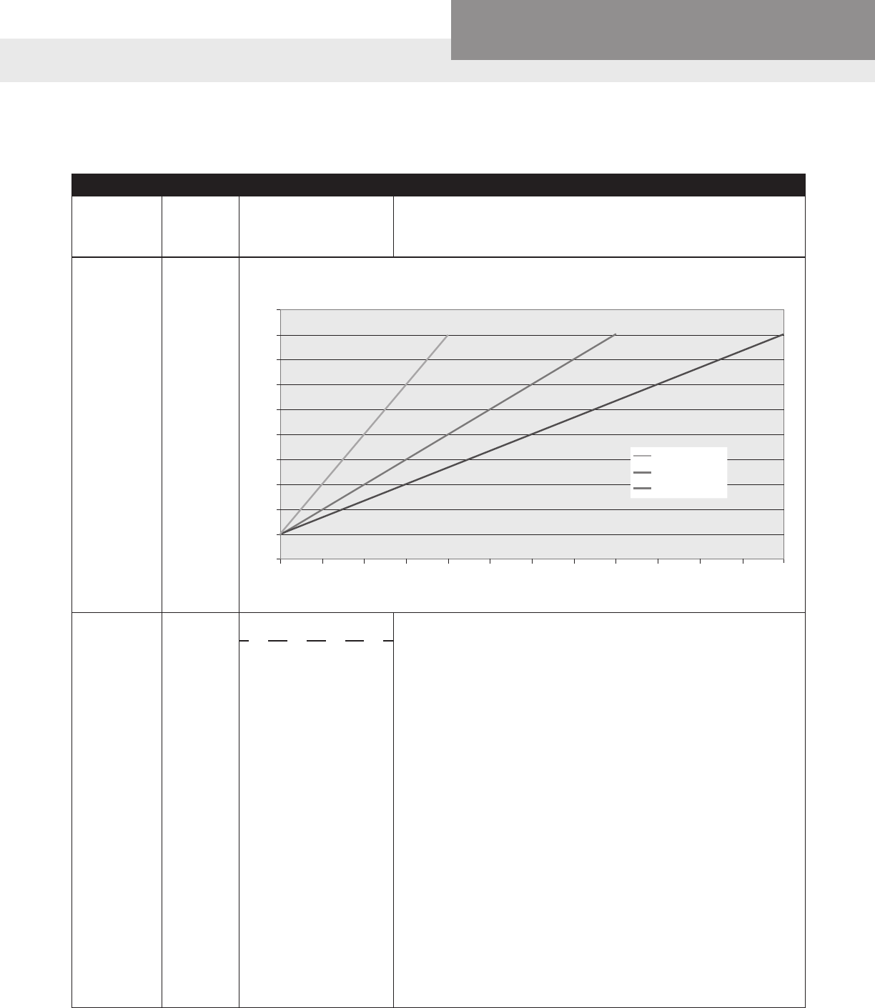
PAGE 40
Residential Water Systems
CentriPro
AQUAVAR SOLO2 TROUBLESHOOTING
FAULT BLINK CODES (continued)
RED LIGHT CODES
Parameter
Display
Fault Code
Flashes Controller Status
Description
This information is to be used by professional installers or
qualied personnel only.
F03 3 Blinks Sensor Fault (continued)
F04 4 Blinks Over Current This fault can be caused by:
• Using wrong motor (wrong voltage or phase).
• Mechanical binding from debris in pump.
• Electrical or mechanical failure of the motor.
• Incorrect setting of “MOTOR OVERLOAD SETTING (SFA)”
switch. The controller will issue an Over Current fault if the
switch is set too low.
The controller estimates the motor temperature by
comparing the output current to the Motor Overload Setting
and monitoring the output frequency. If the motor runs at
high output or is current limiting the motor temperature
estimate increases. If the temperature estimate is too high the
controller stops the motor and issues an Over Current fault.
The controller will automatically clear the fault and restart
the motor after the motor temperature estimate reaches an
acceptable level. If 3 Over Current faults are detected then
the controller must be manually reset by turning off power to
the controller for 1 minute and then on.
The controller stores the motor temperature estimate. If the
controller has tripped on the Over Current fault and power is
turned off and then on, the will not restart unless the motor
temperature estimate is within an acceptable range.
The controller has
turned off the motor
to protect it against
damage due to
an over current or
overload condition. If
3 Over Current faults
are detected, the
controller will need to
be manually reset. If
fault persists contact
installer.
Pressure [PSI]
Sensor Output vs. Applied Pressure
Transducer Output [Volts DC]
0
0
0.5
1
1.5
2
2.5
3
3.5
4
4.5
5
150100
100 PSI 200 PSI 300 PSI
50 250 300200
100 PSI Sensor
200 PSI Sensor
300 PSI Sensor
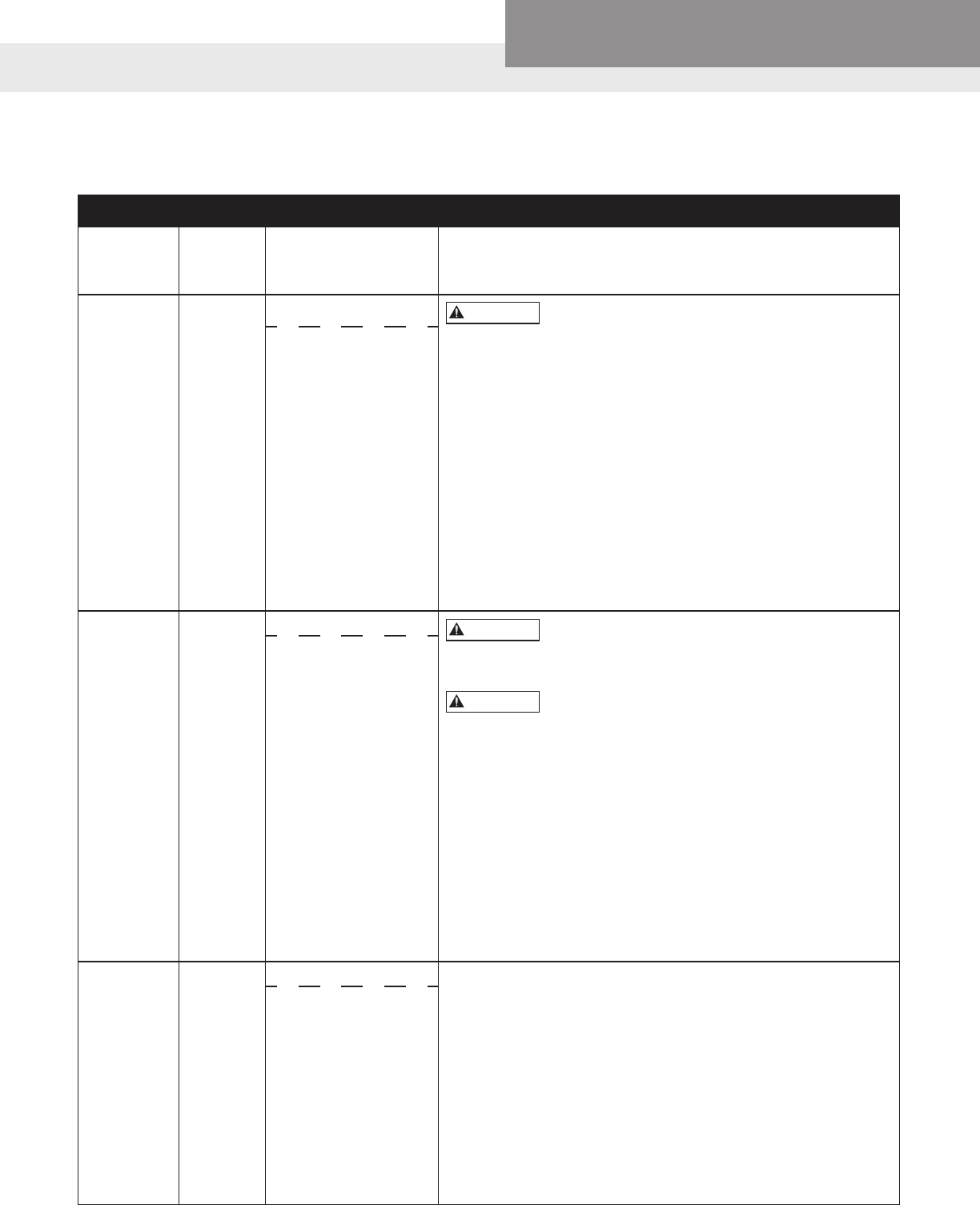
PAGE 41
Residential Water Systems
CentriPro
AQUAVAR SOLO2 TROUBLESHOOTING
FAULT BLINK CODES (continued)
RED LIGHT CODES
Parameter
Display
Fault Code
Flashes Controller Status
Description
This information is to be used by professional installers or
qualied personnel only.
F05 5 Blinks Short Circuit Repeated exposure to Short Circuit conditions
can damage the controller. Do not reset this fault without
xing the short circuit condition more than twice.
This fault can be caused by:
• Electrical failure of the motor.
• Electrical failure of wiring between controller and motor.
Verify the error by turning power to controller off for 1 minute
and then on. If error persists, motor and wiring between
controller and motor must be checked. Turn power off for 5
minutes. Remove the motor wires from the output terminal
block. Check wiring and motor for shorting phase to phase
and phase to ground. Perform the tests described in the
Insulation and Winding Resistance Tests section of this
manual. Refer to motor’s manual for information on resistance
readings.
The controller will not
restart if displaying
this fault. To clear
the fault perform
a System Reset,
or turn off power
to the controller,
wait 1 minute, turn
on power to the
controller. If fault
persists contact
installer.
F06 6 Blinks Ground Fault Repeated exposure to Ground Fault conditions
can damage the controller. Do not reset this fault without
xing the ground fault condition more than twice.
This device does not provide personnel
protection against shock. This function is intended for
equipment protection only.
This fault can be caused by:
• Electrical failure of the motor
• Electrical failure of wiring between controller and motor.
• Miswiring of motor cable.
Verify the error by turning power to controller off for 1 minute
and then on. If error persists, motor and wiring between
controller and motor must be checked. Turn power off and
wait 5 minutes. Remove the motor wires from the output
terminal block. Perform the tests described in the Insulation
and Winding Resistance Tests of this manual.
The controller will not
restart if displaying
this fault. To clear
the fault perform
a System Reset,
or turn off power
to the controller,
wait 1 minute, turn
on power to the
controller. If fault
persists contact
installer.
F07 7 Blinks Temperature This fault can be caused by:
• High ambient temperature. The maximum ambient
temperature rating is 122º F (50º C).
• Low ambient temperature. The minimum ambient
temperature rating is -4º F (-20º C).
Check for a fan failure. The fan will turn on when the
temperature inside the controller reaches 140º F (60º C). The
fan will turn on for 1 second each time the controller starts
the motor. The fan will run for 10 seconds during the rst start
of the motor after power up. If the fan never turns on, check
fan connections and replace as needed. Ensure that the fan is
not bound or clogged
The controller
will automatically
restart when the
temperature reaches
an acceptable level. If
fault persists contact
installer.
WARNING
WARNING
WARNING
PAGE 42
Residential Water Systems
CentriPro
AQUAVAR SOLO2 TROUBLESHOOTING
FAULT BLINK CODES (continued)
RED LIGHT CODES
Parameter
Display
Fault Code
Flashes Controller Status
Description
This information is to be used by professional installers or
qualied personnel only.
F08 8 Blinks Open Lead This fault can be caused by:
• Disconnected or broken wire between the controller and
motor.
Verify the error by turning power to controller off for 1 minute
and then on. If error persists, motor and wiring between
controller and motor must be checked. Turn power off for
5 minutes. Remove the three motor wires from the terminal
block. Using an ohmmeter, measure the resistance from
phase to phase. A disconnected or broken wire will be
indicated by a high resistance reading (20 ohms or higher).
The controller will not
restart if displaying
this fault. To clear
the fault perform
a System Reset,
or turn off power
to the controller,
wait 1 minute, turn
on power to the
controller. If fault
persists contact
installer.
F09 9 Blinks Low Pressure Cut-Off This fault can be caused by:
• Pressure 20 PSI below set point for 30 seconds. May be
a broken pipe or tripped pressure relief valve. If 20 PSI
or more pressure drop for 30 seconds is normal for the
system, switch the Low Pressure Cut-Off protection off or
change system to prevent the pressure drop.
The controller will not
restart if displaying
this fault. To clear
the fault perform
a System Reset,
or turn off power
to the controller,
wait 1 minute, turn
on power to the
controller. If fault
persists contact
installer.
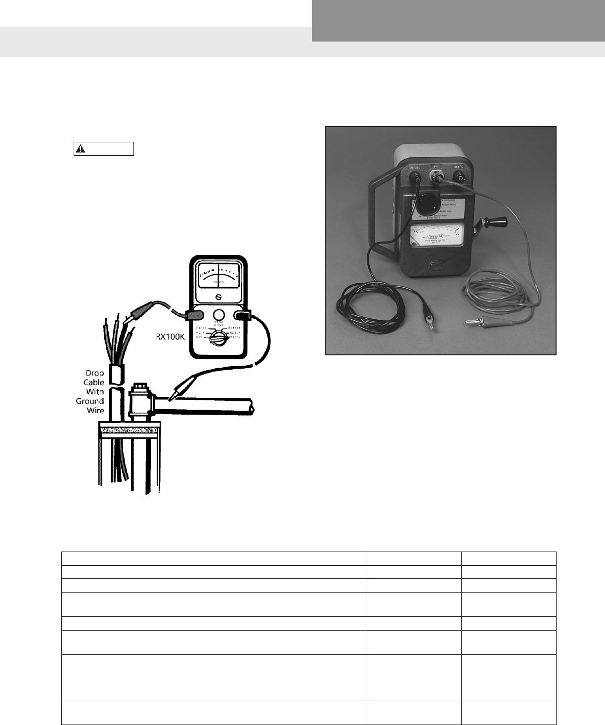
PAGE 43
Residential Water Systems
CentriPro
MEASURING INSULATION RESISTANCE
1. Set the scale lever to R x 100K (R x 100,000) and
set the ohmmeter on zero.
Open (turn off) master breaker
or disconnect all leads from
starter or control box to avoid damage to
meter or electric shock hazard.
2. Connect an ohmmeter lead to any one of the
motor leads and the other to the metal drop
pipe. If the drop pipe is plastic, connect the
ohmmeter lead to the metal well casing or
ground wire.
WARNING
TABLE 1 – Normal Ohm and Megohm Values (Insulation Resistance) Between All Leads and Ground
Insulation resistance does not vary with rating. All motors of all HP, voltage and phase rating have similar values of insulation resistance.
Condition of Motor and Leads Ohm Value Megohm Value
A new motor (without drop cable). 20,000,000 (or more) 20.0
A used motor which can be reinstalled in the well. 10,000,000 (or more) 10.0
Motor in Well. Ohm readings are for drop cable plus motor. A new 2,000,000 (or more) 2.0
motor in the well.
A motor in the well in reasonably good condition. 500,000 - 2,000,000 0.5 - 2.0
A motor which may have been damaged by lightning or with damaged 20,000 - 500,000 0.02 - 0.5
leads. Do not pull the pump for this reason.
A motor which denitely has been damaged or with damaged cable.
The pump should be pulled and repairs made to the cable or the motor 10,000 - 20,000 0.01 - 0.02
replaced. The motor will not fail for this reason alone, but it will
probably not operate for long.
A motor which has failed or with completely destroyed cable insulation. Less than 10,000 0 - 0.01
The pump must be pulled and the cable repaired or the motor replaced.
Megger…
What It Means –
1. If the ohm value is normal, the motor windings
are not grounded and the cable insulation is not
damaged.
2. If the ohm value is below normal, either the
windings are grounded or the cable insulation
is damaged. Check the cable at the well seal as
the insulation is sometimes damaged by being
pinched.
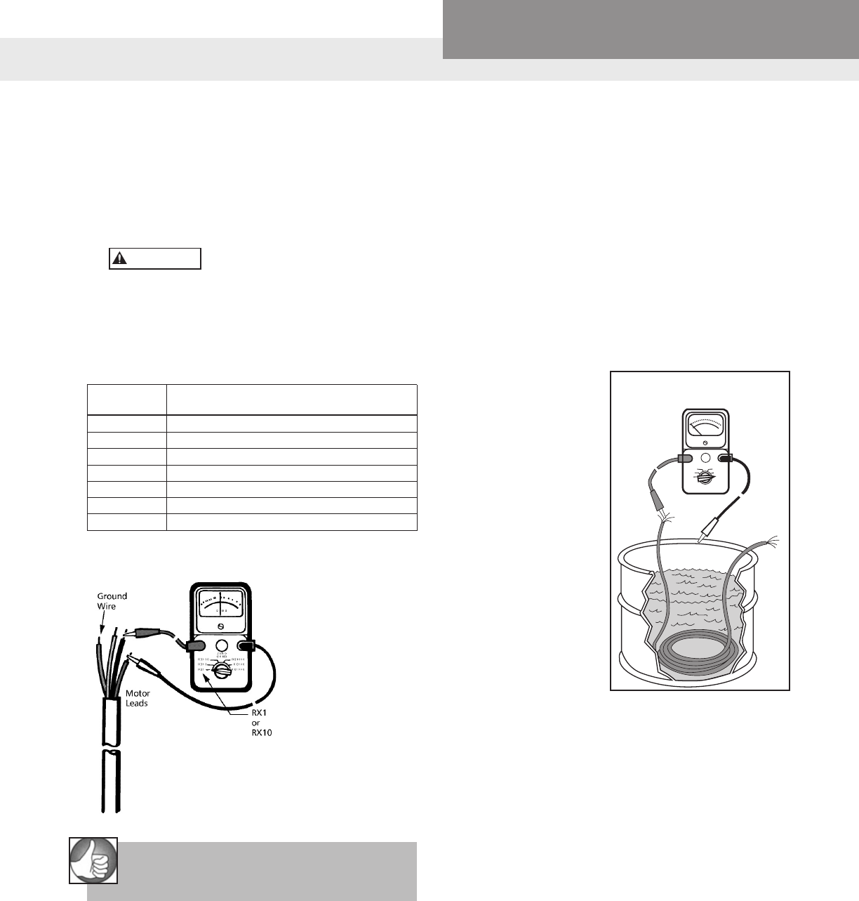
PAGE 44
Residential Water Systems
CentriPro
MOTOR WINDING RESISTANCE CHECKOUT CABLE CHECKOUT
Checking Cable and Splice
1. Submerge cable and splice in steel barrel of water
with both ends out of water.
2. Set ohmmeter selector on RX100K and adjust
needle to zero (0) by clipping ohmmeter leads
together.
3. After adjusting ohmmeter, clip one ohmmeter
lead to barrel and the other to each cable lead
individually, as shown.
4. If the needle deects to zero (0) on any of the cable
leads, pull the splice up out of the water. If the
needle falls back to
(∞) (no reading) the
leak is in the splice.
5. If leak is not in the
splice, pull the cable
out of the water slowly
until needle falls back
to (∞) (no reading).
When the needle falls
back, the leak is at
that point.
6. If the cable or splice
is bad, it should be
repaired or replaced.
What It Means –
1. If all ohm values are
normal, the motor
windings are neither
shorted nor open, and the cable colors are
correct.
2. If any one ohm value is less than normal, the
motor is shorted.
3. If any one ohm value is greater than normal, the
winding or the cable is open or there is a poor
cable joint or connection.
4. If some ohm values are greater than normal and
some less, the leads are mixed.
Measuring Winding Resistance
1. Set the scale lever to R x 1 for values under 10
ohms. For values over 10 ohms, set the scale
lever to R x 10. Zero balance the ohmmeter as
described earlier on page 11.
Open master breaker and
disconnect all leads from
control box to pressure switch (Q-D type
control, remove lid) to avoid damage to meter
or electric shock hazard.
2. Connect the ohmmeter leads as shown below.
TABLE 2 – Cable Resistance – Copper
Cable DC Resistance of Cable per 100 Foot
Size Length Ohms per Pair of Leads
14 .544
12 .338
10 .214
8 .135
6 .082
4 .052
2 .032
If aluminum cable is used the readings will be
higher. Divide the ohm readings on this chart
by 0.61 to
determine the
actual resistance
of aluminum
cable.
See motor data pages
for motor resistance
ratings.
RULE OF THUMB
Add resistance of drop cable when checking
pump in well. See Table 2 above.
CAUTION
Checking Cable and
Splice Test
Attach this lead
to Metal Tank
Ohmmeter
Set at R x 100K
OHMS
R x 1000
R x 10K
R x 100K
R x 100
R x 10
R x 1
ZERO
OHMS
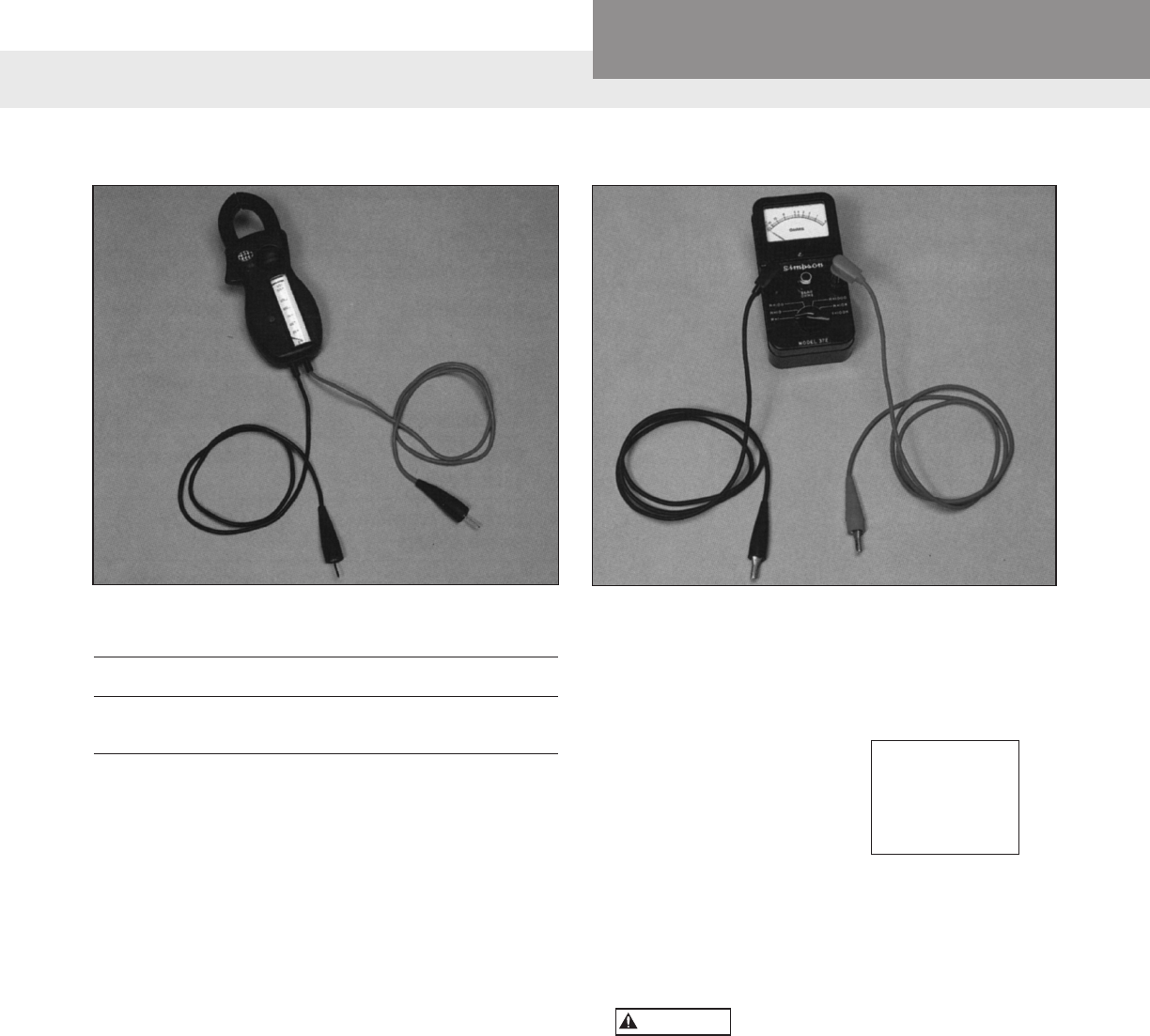
PAGE 45
Residential Water Systems
CentriPro
AMPROBE INSTRUCTIONS
The Amprobe is a multi-range, combination ammeter
and voltmeter.
Voltmeter Scales: 150 VOLTS 600 VOLTS
Ammeter Scales: 5 AMPS 40 AMPS
15 AMPS 100 AMPS
1. When used as an ammeter, the tongs are placed
around the wire being measured with the rotary
scale on the 100 amp range. Then rotate the scale
back to the smaller ranges until an exact reading is
indicated.
2. When used as a voltmeter, the two leads are
clipped into the bottom of the instrument with the
rotary scale on the 600 volt range. If the reading is
less than 150 volts, rotate the scale to the 150 volt
range to get a more exact reading.
OHMMETER INSTRUCTIONS
The Ohmmeter is used for measuring the electrical
resistance of a wire circuit. The unit of measurement is
called an Ohm.
1. The knob at the bottom of the Ohmmeter is
adjustable through six ranges:
RX1 = R x 1
RX10 = R x 10
RX100 = R x 100
RX1000 = R x 1,000
RX10K = R x 10,000
RX100K = R x 100,000
2. The round center knob is for the purpose of
adjusting the instrument to zero (0) after clipping
the two ohmmeter leads together. This must be
done every time the range selection is changed.
Use Ohmmeter only with POWER
OFF.
If your ohmmeter
is digital readout
type, refer to the
instructions that
came with it.
CAUTION
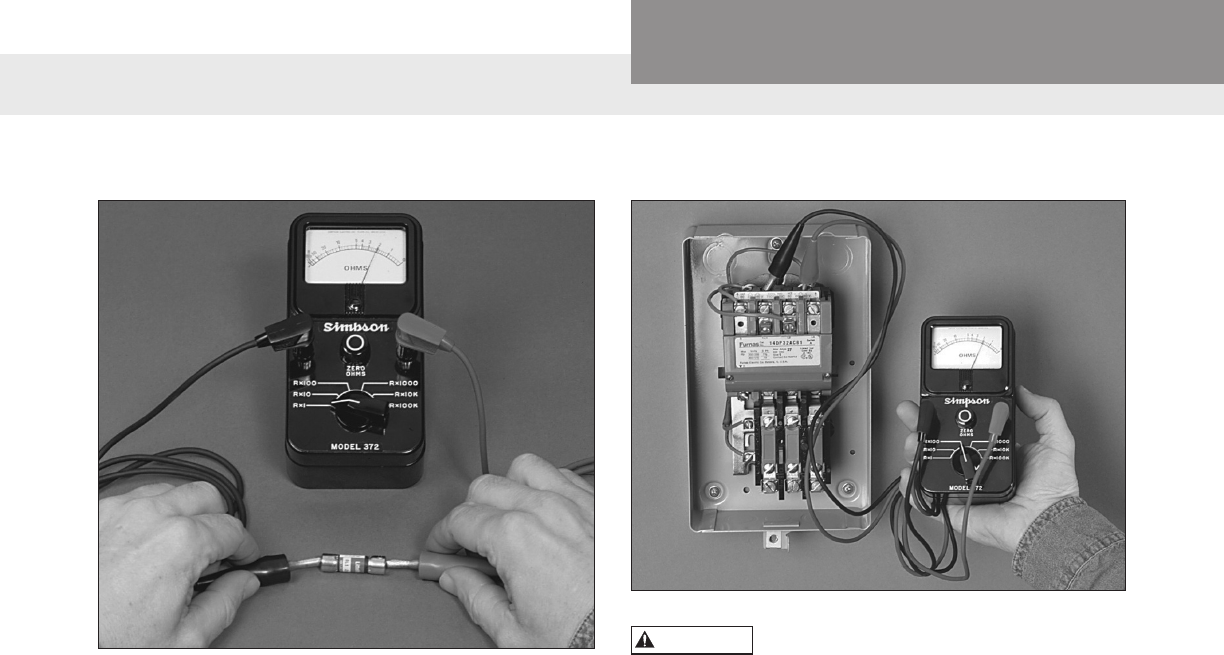
PAGE 46
Residential Water Systems
CentriPro
FUSE CHECKOUT
1. Set R x 1.
2. Connect leads as shown.
3. Reading: Should register zero.
What It Means –
Zero reading indicates fuse OK. Innity (∞) reading
indicates bad fuse.
3 PHASE STARTER COIL CHECKOUT
Open master breaker and disconnect
all leads from starter to avoid
damage to meter or electric shock hazard. Connect
the ohmmeter leads as shown above.
Coil with Ohmmeter
1. Set R x 1,000.
2. Connect leads as shown.
3. Reading: Should register some value,
Approximately 200-1000 ohms.
What It Means –
Innity reading indicates coil is open. Zero reading
indicates coil is shorted. In either case, the coil
should be replaced.
A reading of 200-1000 ohms indicates coil is ok.
WARNING
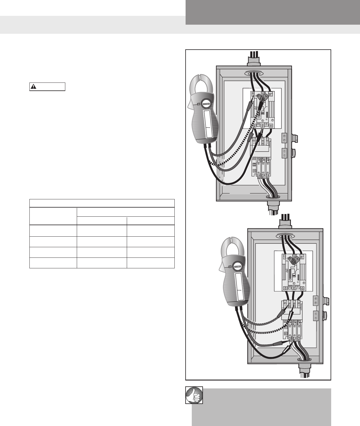
PAGE 47
Residential Water Systems
CentriPro
VOLT
600 -
500 -
400 -
300 -
200 -
100 -
0 -
3 PHASE STARTER VOLTAGE CHECKOUT
Checking Voltage at Fused Disconnect and
Magnetic Starter
POWER IS ON during voltage
checking.
1. To check voltage: Use voltmeter on L1, L2 and L3 in
sequence. Check should be made at four locations.
Step 1 Checking incoming power supply.
Step 2 Checking fuses.
Step 3 Checking contact points
Step 4 Checking heaters.
2. When checking voltage, all other major electrical
appliances (that could be in use at the same time)
should be running.
3. If incoming power supply readings are not within
the limits (see chart), call your power supplier.
Voltage Limits
Name Plate Measured Volts
▼ Minimum Maximum
208V 3Ø 188 228
230V 3Ø 207 253
460V 3Ø 414 506
575V 3Ø 518 632
NOTE: Phase to phase – full line voltage. Phase to
neutral – ½ full line voltage. (depending on
transformer connection)
WARNING
VOLT
600 -
500 -
400 -
300 -
200 -
100 -
0 -
RULE OF THUMB
Incoming power should be within 5% of power
supply voltage. Motors are rated ±10% of
nameplate. The other 5% is used for cable voltage
drop.
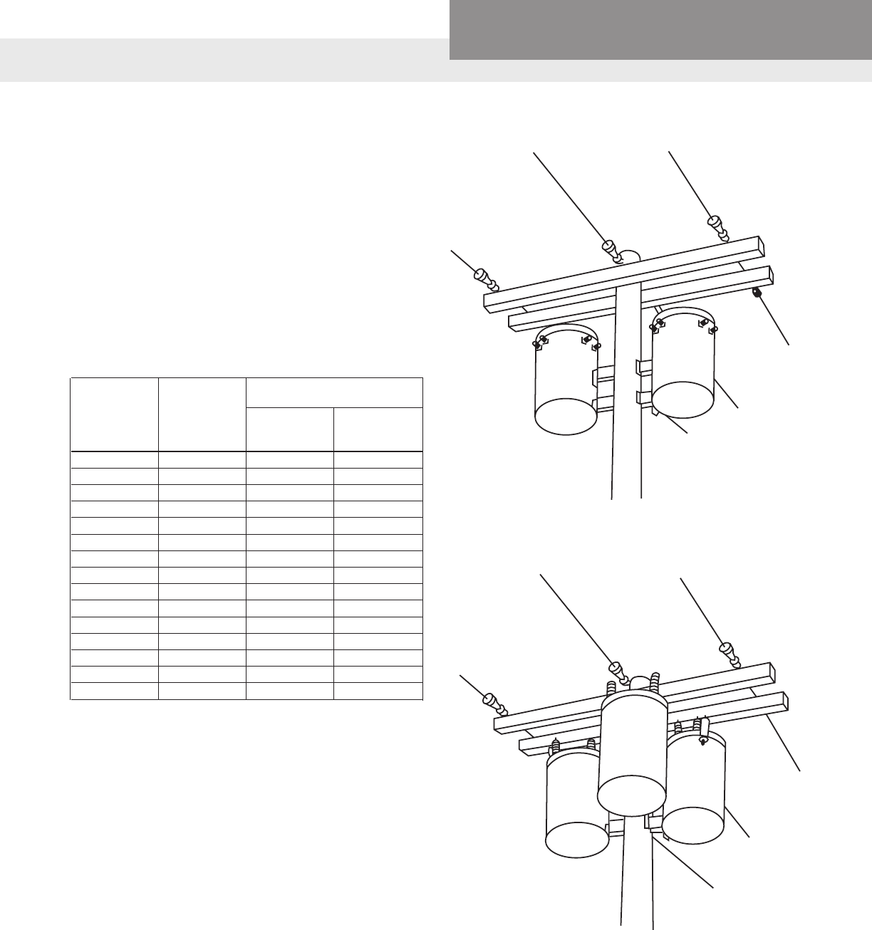
PAGE 48
Residential Water Systems
CentriPro
TRANSFORMER SIZES
A full three phase supply is recommended for all three
phase motors, consisting of three individual trans-
formers or one three phase transformer. “Open” delta
or wye connections using only two transformers can
be used, but are more likely to cause problems from
current unbalance.
Transformer ratings should be no smaller than listed in
the table for supply power to the motor alone.
TRANSFORMER CAPACITY REQUIRED FOR SUB-
MERSIBLE MOTORS
Smallest KVA Rating –
Submersible Total Effective Each Transformer
3Ø Motor KVA Open WYE WYE or
HP Rating Required DELTA 2 DELTA 3
Transformers Transformers
1½ 3 2 1
2 4 2 1½
3 5 3 2
5 7½ 5 3
7½ 10 7½ 5
10 15 10 5
15 20 15 7½
20 25 15 10
25 30 20 10
30 40 25 15
40 50 30 20
50 60 35 20
60 75 40 25
75 90 50 30
100 120 65 40
FULL THREE PHASE
OPEN DELTA OR WYE
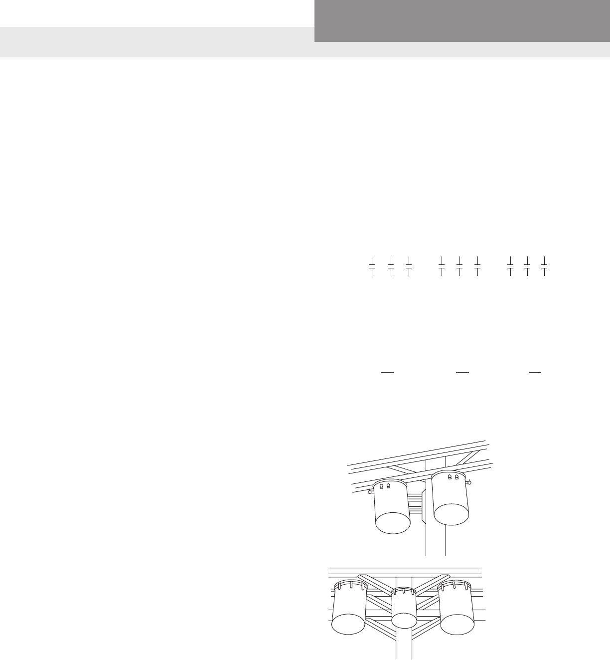
PAGE 49
Residential Water Systems
CentriPro
Hookup 1 Hookup 2 Hookup 3
L1 L2 L3 L1 L2 L3 L1 L2 L3
Starter
Terminals
T1 T2 T3 T1 T2 T3 T1 T2 T3
Motor R B Y Y R B B Y R
Leads T3 T1 T2 T2 T3 T1 T1 T2 T3
Example:
T3-R = 51 amps T2-Y = 50 amps T1-B = 50 amps
T1-B = 46 amps T3-R = 48 amps T2-Y = 49 amps
T2-Y = 53 amps T1-B = 52 amps T3-R = 51 amps
Total = 150 amps Total = 150 amps Total = 150 amps
÷ 3 = 50 amps ÷ 3 = 50 amps ÷ 3 = 50 amps
— 46 = 4 amps — 48 = 2 amps — 49 = 1 amps
4 ÷ 50 = .08 or 8% 2 ÷ 50 = .04 or 4% 1 ÷ 50 = .02 or 2%
THREE PHASE POWER UNBALANCE
A full three phase supply is recommended for all
three phase motors, consisting of three individual
transformers or one three phase transformer. So-
called “open” delta or wye connections using only two
transformers can be used, but are more likely to cause
problems, such as poor performance overload trip-
ping or early motor failure due to current unbalance.
Transformer ratings should be no smaller than listed
on Transformer Size Chart on previous page.
Phase designation of leads for CCW rotation view-
ing shaft end.
To reverse rotation, interchange any two leads.
Phase 1 or “A” – Black Motor Lead or T1
Phase 2 or “B” – Yellow Motor Lead or T2
Phase 3 or “C” – Red Motor Lead or T3
Notice: Phase 1, 2 and 3 may not be L1, L2 and L3.
Checking and correcting rotation
and current unbalance
1. Establish correct motor rotation by running in both
directions. Change rotation by exchanging any two
of the three motor leads. The rotation that gives the
most water ow is always the correct rotation.
2. After correct rotation has been established, check
the current in each of the three motor leads and cal-
culate the current unbalance as explained in 3 below.
If the current unbalance is 2% or less, leave the leads
as connected.
If the current unbalance is more than 2%, current
readings should be checked on each leg using each
of the three possible hook-ups. Roll the motor leads
across the starter in the same direction to prevent
motor reversal.
3. To calculate percent of current unbalance:
A. Add the three line amp values together.
B. Divide the sum by three, yielding average current.
C. Pick the amp value which is furthest from the aver-
age current (either high or low).
D. Determine the difference between this amp value
(furthest from average) and the average.
E. Divide the difference by the average.
Multiply the result by 100 to determine percent of
unbalance.
4. Current unbalance should not exceed 5% at service
factor load or 10% at rated input load. If the unbal-
ance cannot be corrected by rolling leads, the source
of the unbalance must be located and corrected. If,
on the three possible hookups, the leg farthest from
the average stays on the same power lead, most of
the unbalance is coming from the power source.
However, if the reading farthest from average moves
with the same motor lead, the primary source of
unbalance is on the “motor side” of the starter. In this
instance, consider a damaged cable, leaking splice,
poor connection, or faulty motor winding.
OPEN DELTA
OR WYE
FULL THREE
PHASE
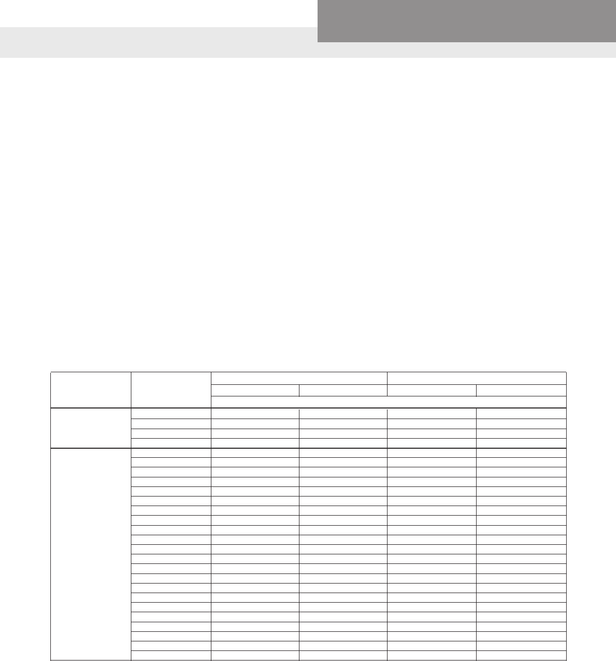
PAGE 50
Residential Water Systems
CentriPro
Note: Always consult the generator
manufacturer whenever questions arise.
These sizing charts are recommendations based on
motor service factor loading for typical continuous
duty generators. If you need to call the generator
manufacturer, be prepared to tell them the motor KVA
code, the service factor amperage, locked rotor am-
perage, phase, hertz, motor type, etc. This information
can all be found in this manual.
Please note that the 2-wire chart is only for PSC
(permanent split capacitor) type, 2-wire motors and
should not be used for split-phase, 2-wire motors. If
using split-phase, 2-wire motors the generator should
be 50% larger than that listed for a 3-wire motor.
You must know which type generator you have before
using the charts as the required generator size varies
by type. Internally regulated generators are also called
self-excited. Externally regulated generators are the
most common. In addition to the Kw/KVA rating, the
generator frequency (Hertz, typically 60 HZ in USA) is
very important when operating pumping equipment
because frequency variations affect pump output in
direct relation to the pump Afnity Laws. Operating
under 60 hertz will reduce ow and head while op-
erating over 60 hertz will increase ow, head, HP and
amp draw and could overload the motor.
The generator should always be started before the
pump/motor is started and always stop the pump/
motor before shutting down the generator. Operat-
ing generators at higher elevations or using natural
gas a fuel can affect performance, consult the genera-
tor manufacturer for their recommendations in these
instances.
GENERATOR SIZING
GENERATOR RECOMMENDATIONS
Externally Regulated Internally Regulated
Motor HP KW KVA KW KVA
Minimum Generator Rating
PSC .5 2.5 3.1 1.75 2.2
Type .75 3.5 4.4 2.5 3.1
2-Wire 1 5 6.3 3.2 4
1Ø 1.5 6 7.5 4 5
.5 2 2.5 1.5 1.9
.75 3 3.8 2 2.5
1 4 5 2.5 3.2
1.5 5 6.3 3 3.8
2 7.5 9.4 4 5
3 10 12.5 5 6.3
5 15 18.8 7.5 9.4
7.5 20 25 10 12.5
3-Wire 10 30 37.5 15 18.8
1Ø 15 40 50 20 25
and 20 60 75 25 31
3Ø 25 75 94 30 37.5
Motors 30 100 125 40 50
40 100 125 50 62.5
50 150 188 60 75
60 175 220 75 94
75 250 313 100 125
100 300 375 150 188
125 375 469 175 219
150 450 563 200 250
175 525 656 250 313
200 600 750 275 344
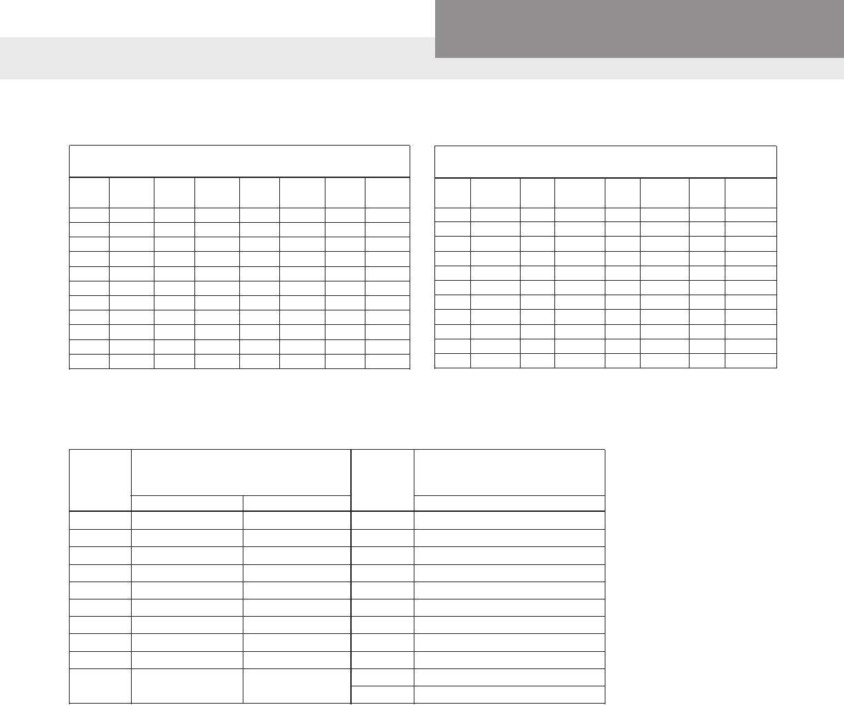
PAGE 51
Residential Water Systems
CentriPro
1. Feet Head of Water and Equivalent Pressures
To change head in feet to pressure in pounds, multiply by .434
Feet PSI Feet
PSI Feet PSI Feet PSI
Head Head Head Head
1 .43 30 12.99 140 60.63 300 129.93
2 .87 40 17.32 150 64.96 325 140.75
3 1.30 50 21.65 160 69.29 350 151.58
4 1.73 60 25.99 170 73.63 400 173.24
5 2.17 70 30.32 180 77.96 500 216.55
6 2.60 80 34.65 190 82.29 600 259.85
7 3.03 90 38.98 200 86.62 700 303.16
8 3.46 100 43.31 225 97.45 800 346.47
9 3.90 110 47.64 250 108.27 900 389.78
10 4.33 120 51.97 275 119.10 1000 433.09
20 8.66 130 56.30 – – – –
HEAD AND PRESSURE EQUIVALENTS
2. Pressure and Equivalent Feet Head of Water
To change pounds pressure to feet head, multiply by 2.3
PSI Feet PSI Feet PSI Feet PSI Feet
Head Head Head Head
1 2.31 20 46.18 120 277.07 225 519.51
2 4.62 25 57.72 125 288.62 250 577.24
3 6.93 30 69.27 130 300.16 275 643.03
4 9.24 40 92.36 140 323.25 300 692.69
5 11.54 50 115.45 150 346.34 325 750.41
6 13.85 60 138.54 160 369.43 350 808.13
7 16.16 70 161.63 170 392.52 375 865.89
8 18.47 80 184.72 180 415.61 400 922.58
9 20.78 90 207.81 190 438.90 500 1154.48
10 23.09 100 230.90 200 461.78 1000 2309.00
15 34.63 110 253.98 – – – –
APPROXIMATE COST OF OPERATING ELECTRIC MOTORS
*Average kilowatts input or cost
*Av. kw input or cost per hour
Motor based on 1 cent per kilowatt hour Motor
based on 1 cent per kw hour
HP HP
1 Phase 3 Phase 3 Phase
1⁄3 .408 20 16.9
½ .535 .520 25 20.8
¾ .760 .768 30 26.0
1 1.00 .960 40 33.2
1½ 1.50 1.41 50 41.3
2 2.00 1.82 60 49.5
3 2.95 2.70 75 61.5
5 4.65 4.50 100 81.5
7½ 6.90 6.75 125 102
10 9.30 9.00 150 122
200 162
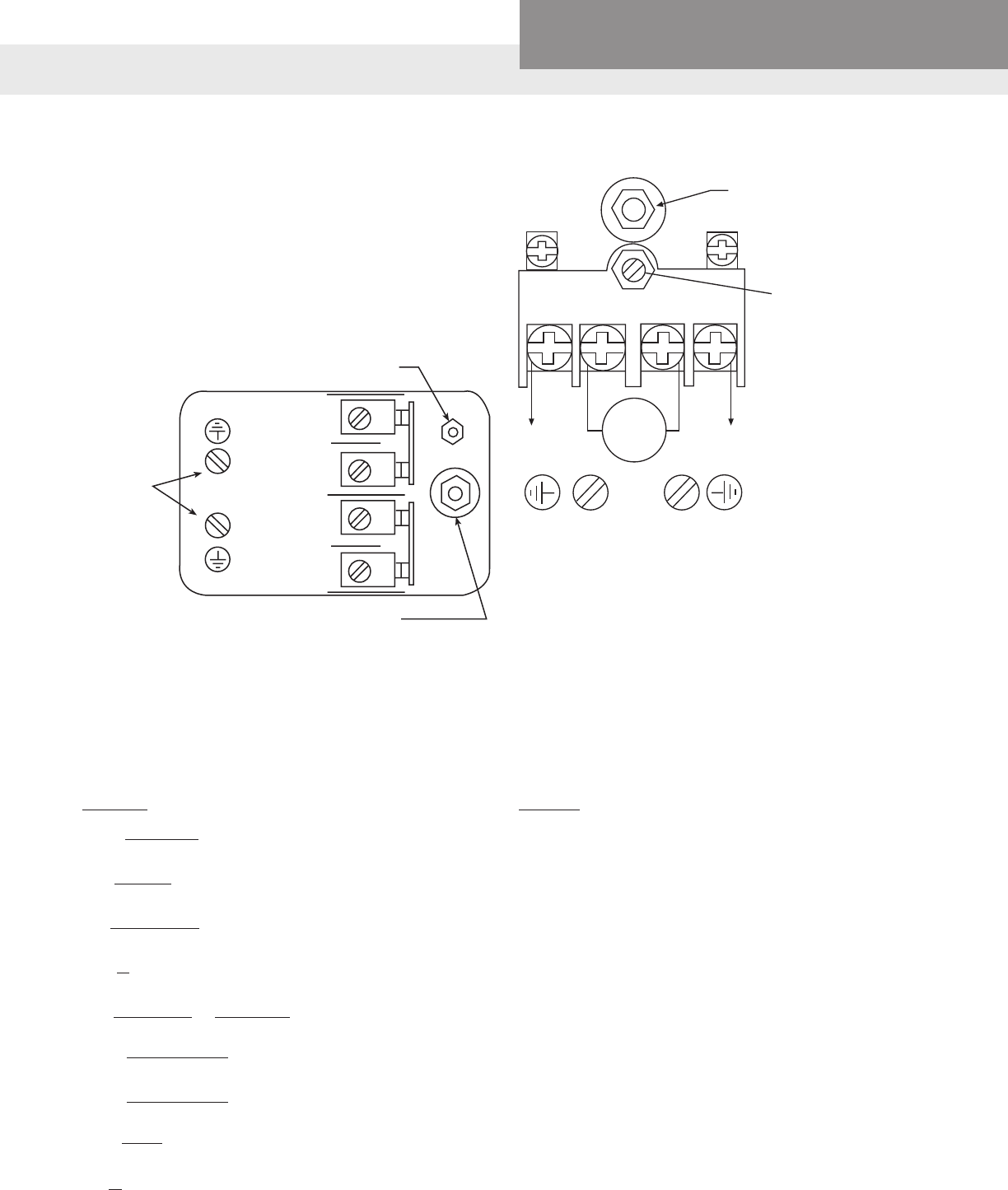
PAGE 52
Residential Water Systems
CentriPro
BASIC FORMULAS AND SYMBOLS
Formulas
GPM = Lb./Hr.
500 x Sp. Gr.
H = 2.31 x psi
Sp. Gr.
H = 1.134 x In. Hg.
Sp. Gr.
HV = V2 = 0.155 V2
2g
V = GPM x 0.321 = GPM x 0.409
A (I.D.)2
BHP = GPM x H x Sp. Gr.
3960 x Eff.
Eff. = GPM x H x Sp. Gr.
3960 x BHP
NS = N√GPM
H3/4
H = V2
2g
Symbols
GPM = gallons per minute
Lb. = pounds
Hr. = hour
Sp. Gr. = specic gravity
H = head in feet
psi = pounds per square inch
In. Hg. = inches of mercury
hv = velocity head in feet
V = velocity in feet per second
g = 32.16 ft./sec.2 (acceleration of gravity)
A = area in square inches (πr2) (for a circle or pipe)
ID = inside diameter in inches
BHP = brake horsepower
Eff. = pump efciency expressed as a decimal
NS = specic speed
N = speed in revolutions per minute
D = impeller in inches
CENTRIPRO OR SQUARE "D" SWITCHES
Grounding
Provisions
#8-32 screws
Range: adjust
for cut-in point
Differential: adjust
for cut-out point
ADJUSTMENT
Line
L1
Load
Load
Line
L2
LINE LOAD LOAD LINE
MOTOR
L1 L2
MAIN SPRING ADJUSTMENT
Turn clockwise to increase both cut-out
and cut-in pressure. (2 PSI/turn)
DIFFERENTIAL
ADJUSTMENT
Turn clockwise to increase
cut-out pressure without
affecting cut-in. (3 PSI/turn)
FURNAS PRO CONTROL
Adjust in proper sequence:
1. CUT-IN: Turn nut down for higher cut-in pressure, or
up for lower cut-in.
2. CUT-OUT: Turn nut down for higher cut-out pres-
sure, or up for lower cut-out.
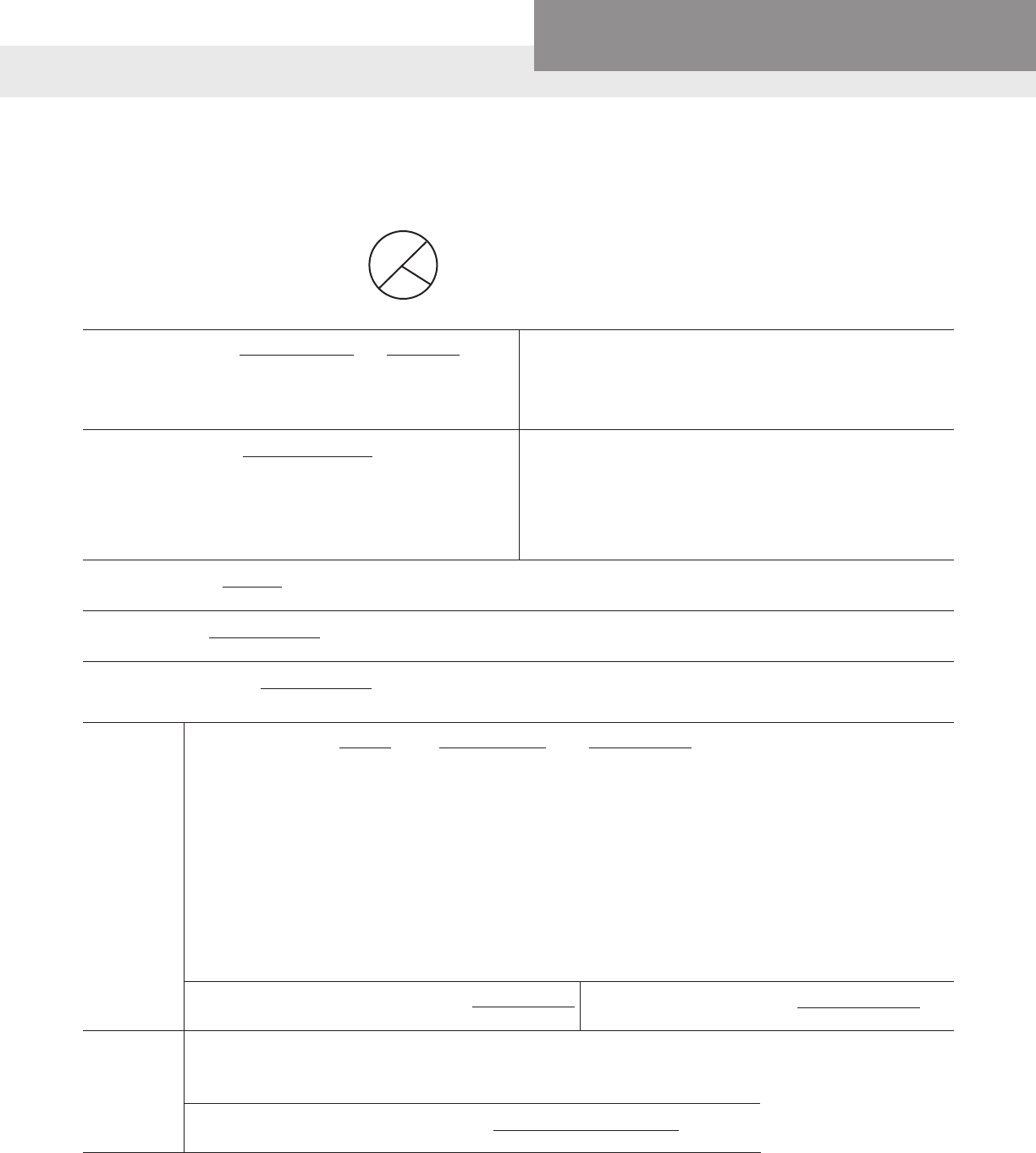
PAGE 53
Residential Water Systems
CentriPro
BASIC FORMULAS AND SYMBOLS
Water Horsepower = GPM x 8.33 x Head = GPM x Head
33000 3960
Temperature conversion
DEG. C = (DEG. F – 32) x .555
DEG. F = (DEG. C x 1.8) + 32
Area of a Circle
A = area; C = circumference.
A =π r2; π = 3.14
C = 2πr
r
CIRCLE
d
Where:
GPM = Gallons per Minute
8.33 = Pounds of water per gallon
33000 = Ft. Lbs. per minute in one horsepower
Head = Difference in energy head in feet (eld head).
Laboratory BHP = Head x GPM x Sp. Gr.
3960 x Eff.
Field BHP = Laboratory BHP + Shaft Loss
Total BHP = Field BHP + Thrust Bearing Loss
Where:
GPM = Gallons per Minute
Head = Lab. Head (including column loss)
Eff. = Lab. Eff. of Pump Bowls
Shaft Loss = HP loss due to mechanical friction of lineshaft bearings
Thrust Bearing Loss = HP Loss in driver thrust bearings
(See (1) below under Misc.)
Input Horsepower = Total BPH
Motor Eff.
Motor Eff. from Motor mfg. (as a decimal)
Field Efciency = Water Horsepower
Total BHP
Water HP as determined above
Total BHP as determined above
Overall Plant Efciency = Water Horsepower
Input Horsepower
(See (2) below under Misc.)
Water HP as determined above
Input HP as determined above
Input Horsepower = BHP = 4.826 x K x M x R = 1.732 x E x I x PF
Mot. Eff. T 746
BHP = Brake Horsepower as determined above
Mot. Eff. = Rated Motor Efciency
K = Power Company Meter Constant
M = Power Company Meter Multiplier, or Ratio of Current and Potential
Transformers connected with meter
R = Revolutions of meter disk
T = Time in Sec. for R
E = Voltage per Leg applied to motor
I = Amperes per Leg applied to motor
PF = Power factor of motor
1.732 = Factor for 3-phase motors. This reduces to 1 for single phase motors
Electrical
Miscellaneous
Kilowatt input to Motor = .746 x I.H.P. = 1.732 x E x I x PF
1000
KW-Hrs. Per 1000 Gallons of = HD in ft. x 0.00315
Cold Water Pumped Per Hour Pump Eff. x Mot. Eff.
(1) Thrust Bearing Loss = .0075 HP per 100 RPM per 1000 lbs. thrust.*
(2) Overall Plant Efciency sometimes referred to as “Wire to Water” Efciency
*Thrust (in lbs.) = (thrust constant (k) laboratory head) + (setting in feet x shaft wt. per ft.)
Note: Obtain thrust constant from curve sheets
Discharge Head (in feet of uid pumped) = Discharge Pressure (psi) x 2.31
Sp. Gr. of Fluid Pumped
D = diameter
r = radius
TERMS AND USABLE FORMULAS
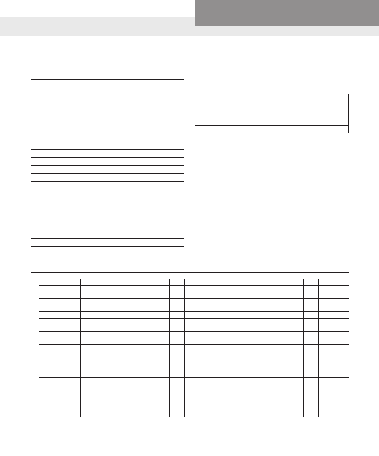
PAGE 54
Residential Water Systems
CentriPro
TABLE 2 – PRESSURE FACTORS
Pump Cut-In Pressure – PSIG
20 25 30 35 40 45 50 55 60 65 70 75 80 85 90 95 100 105 110 115
30 .22
35 .30 .20
40 .37 .27 .18
45 .42 .34 .25 .17
50 .46 .39 .31 .23 .15
55 .50 .43 .36 .29 .22 .14
60 .54 .47 .40 .33 .27 .20 .13
65 .50 .44 .38 .31 .25 .19 .13
70 .53 .47 .41 .35 .30 .24 .18 .12
75 .50 .45 .39 .33 .28 .22 .17 .11
80 .53 .48 .42 .37 .32 .26 .21 .16 .11
85 .50 .45 .40 .35 .30 .25 .20 .15 .10
90 .53 .48 .43 .38 .33 .29 .24 .19 .14 .10
95 .50 .46 .41 .36 .32 .27 .23 .18 .14 .09
100 .52 .48 .44 .39 .35 .31 .26 .22 .17 .13 .09
105 .50 .46 .42 .38 .33 .29 .25 .21 .17 .13 .08
110 .52 .46 .44 .40 .36 .32 .28 .24 .20 .16 .12
115 .50 .46 .42 .39 .35 .31 .27 .23 .19 .15 .12 .06
120 .52 .48 .45 .41 .37 .33 .30 .26 .22 .19 .15 .11
125 .50 .47 .43 .39 .36 .32 .29 .25 .21 .16 .14 .11 .07
To determine tank drawdown of operating pressure ranges other than those listed in table, use following procedure:
Multiply total tank volume (table 1) by pressure factor (table 4).
Example: Operating range: 35/55
Tank being used: V-200
65.1 = Total volume of tank (table 1)
x .29 Pressure factor (table 4)
18.9 = Drawdown in gallons at 35/55 PSI operating range.
Pump Cut-Out Pressure – PSIG
TABLE 1 – TANK MODELS – See your Full Line Catalog Tank Bulletins for a listing of all available models.
① Drawdown based on a 22 psi differential and Boyle’s Law. Tem-
perature, elevation and pressure can all affect drawdown volume.
HYDROPRO AND CENTRIPRO TANK SELECTION
Tank Drawdown Pressure Factors Using an “Extra”
2 PSI of Drawdown
Pressure Differential Factor with extra 2 psi*
18 – 40 .402
28 – 50 .340
38 – 60 .295
48 – 70 .260
To Calculate drawdown capacity multiply: Factor x Tank Volume.
Model
No.
Total
Volume
(Gals.)
① Drawdown in Gals. at System
Operating Pressure Range of Maximum
Drawdown
Volume
(Gallons)
18/40
PSIG
28/50
PSIG
38/60
PSIG
V6P 1.9 0.7 0.6 0.5 1.3
V15P 4.9 1.8 1.5 1.4 3.1
V25P 7.3 2.7 2.3 2.1 3.1
V45P 13.9 5.6 4.7 4.1 8.4
V45 13.9 5.6 4.7 4.1 8.4
V60B 19.9 8.0 6.8 5.8 12.1
V60 19.9 8.0 6.8 5.8 12.1
V80 25.9 10.4 8.8 7.6 13.9
V80EX 25.9 10.4 8.8 7.6 13.9
V100 31.8 12.8 10.8 9.4 13.8
V100S 31.8 12.8 10.8 9.4 13.8
V140B 45.2 18.2 15.4 13.3 27.3
V140 45.2 18.2 15.4 13.3 27.3
V200 65.1 26.2 22.1 19.2 39.3
V250 83.5 33.6 28.4 25.6 50.8
V260 84.9 34.1 28.9 25.0 44.7
V350 115.9 46.6 39.4 34.1 70.5
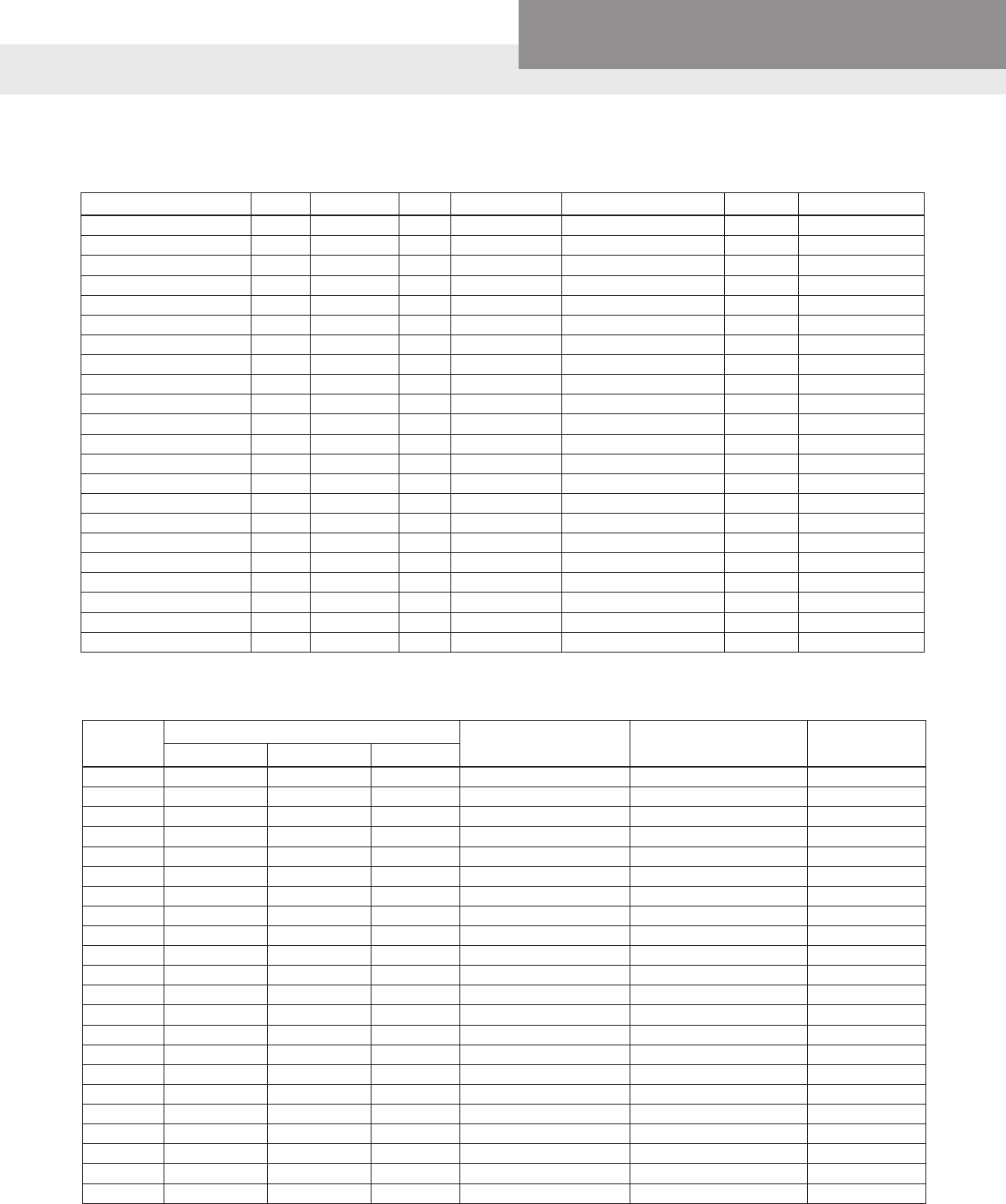
PAGE 55
Residential Water Systems
CentriPro
MOTOR DATA
ELECTRICAL COMPONENTS
JET PUMP MOTOR DATA AND ELECTRICAL COMPONENTS
GWT Motor
Model
Motor Overload with Leads Run Capacitor and MFD Start Capacitor
MFD Rating Switch ⑤
④ Old Number ③ New Number T.I. Number
J04853 614246 71 MET38ABN 610807 1: 124/148 629002 2
J05853 614246 20 CET63ABN 610807 2: 161/192 629002 2
J06853 614246 9 CET52ABN 610807 2: 161/192 629002 2
J07858 614246 79 CET38ABM 610807 2: 161/192 629002 2
J08854 611307 29 BRT44ABM 614529 4: 25 610807 1: 124/148 629002 2
J09853 611106 22 611106 36 BRB2938 628318 314: 55 610807 11; 36-43 629002 2
J04853L 614246 98 627121 43 MET39ABN-CL 610807 1:124/148 629002 2
J05853L 614246 20 627121 38 CET63ABN 610807 2:161/192 629002 2
J06853L 614246 9 627121 7 CET52ABN 610807 2:161/192 629002 2
J07858L 611123 21 BRT45ABM 610807 7:189/227 629002 2
J08854L 616861 10 627119 10 CET31ABN 623450 8: 30 610807 33: 64-77 629002 2
SFJ04853 621863 1 MEJ38ABN N/A 3945C91A01
SFJ05853 621863 4 CET55ABN 610807 2: 161/192 3945C91A01
SFJ06853 621863 5 CET49ABN 610807 2: 161/192 3945C91A01
SFJ04860 614246 67 627121 48 MET36ABN 610807 2: 161/192 629002 2
SFJ05860 614246 20 627121 38 CET63ABN 610807 2: 161/192 629002 2
SFJ06860 614246 9 627121 7 CET52ABN 610807 2: 161/192 629002 2
J05853N P751056520063 CEJ65CV N/A C103237300109: 238/110 X837648580001
J06853N P751056520251 CEJ-49CV N/A C103237300109: 238/110 X837648580001
J07858N P751056520253 CEJ49CY C107558550064: 50/370 C103237300120: 208/165 X837406460002
J08854N P751056520249 CEJ-38CS C107558550064: 50/370 C103237300127: 59/250 X837406460002
J09853N P751056520192 CEJ31CY
C107558550064: 50/370
C103237300127: 59/250 X837406460002
③ These new overload part numbers are for use with the new plastic terminal board with the quick change voltage plug.
④ Use this sufx if your motor has the old style brown terminal board without quick change voltage plug.
⑤ 629002 2 replaces 614234 1, 2, and 6.
GWT Number HP Volts Phase Service Factor Maximum Load Amps Watts Circuit Breaker
J04853 ½ 115/230 1 1.6 10.8/5.4 880 25/15
J05853 ¾ 115/230 1 1.5 14.8/7.4 1280 30/15
J06853 1 115/230 1 1.4 16.2/8.1 1440 30/20
J07858 1½ 115/230 1 1.3 20.0/10.0 1866 40/20
J08854 2 115/230 1 1.2 22.6/11.3 2100 25/15
J09853 3 230 1 1.15 13.3 3280 30
J04853L ½ 115/230 1 1.6 10.8/5.4 968 25/15
J05853L ¾ 115/230 1 1.5 14.8/7.4 1336 30/15
J06853L 1 115/230 1 1.4 16.2/8.1 1592 30/20
J07858L 1½ 115/230 1 1.3 21.4/10.7 1950 40/20
①J08854L 2 230 1 1.2 12.9 2100 25
SFJ04853 ½ 115/230 1 1.6 9.4/4.7 900 20/10
SFJ05853 ¾ 115/230 1 1.5 13.6/6.8 1160 25/15
SFJ06853 1 115/230 1 1.4 15.8/7.9 1400 30/20
SFJ04860 ½ 115/230 1 1.6 12.6/6.3 990 25/15
SFJ05860 ¾ 115/230 1 1.5 14.8/7.4 1200 30/15
SFJ06860 1 115/230 1 1.4 16.2/8.1 1400 30/20
J05853N ¾ 230/115 1 1.5 13.8/6.9 1294 40 / 20
J06853N 1 230/115 1 1.6 16.8/8.4 1691 45 / 20
J07858N 2 230/115 1 1.7 20.4/10.2 2350 50 / 25
J08854N 2 230 1 1.4 12 2604 30
J09853N 3 230 1 1.2 14.5 3278 45
① Effective July, 1998, 230 V only. Note: Refer to motor nameplate for motor part number
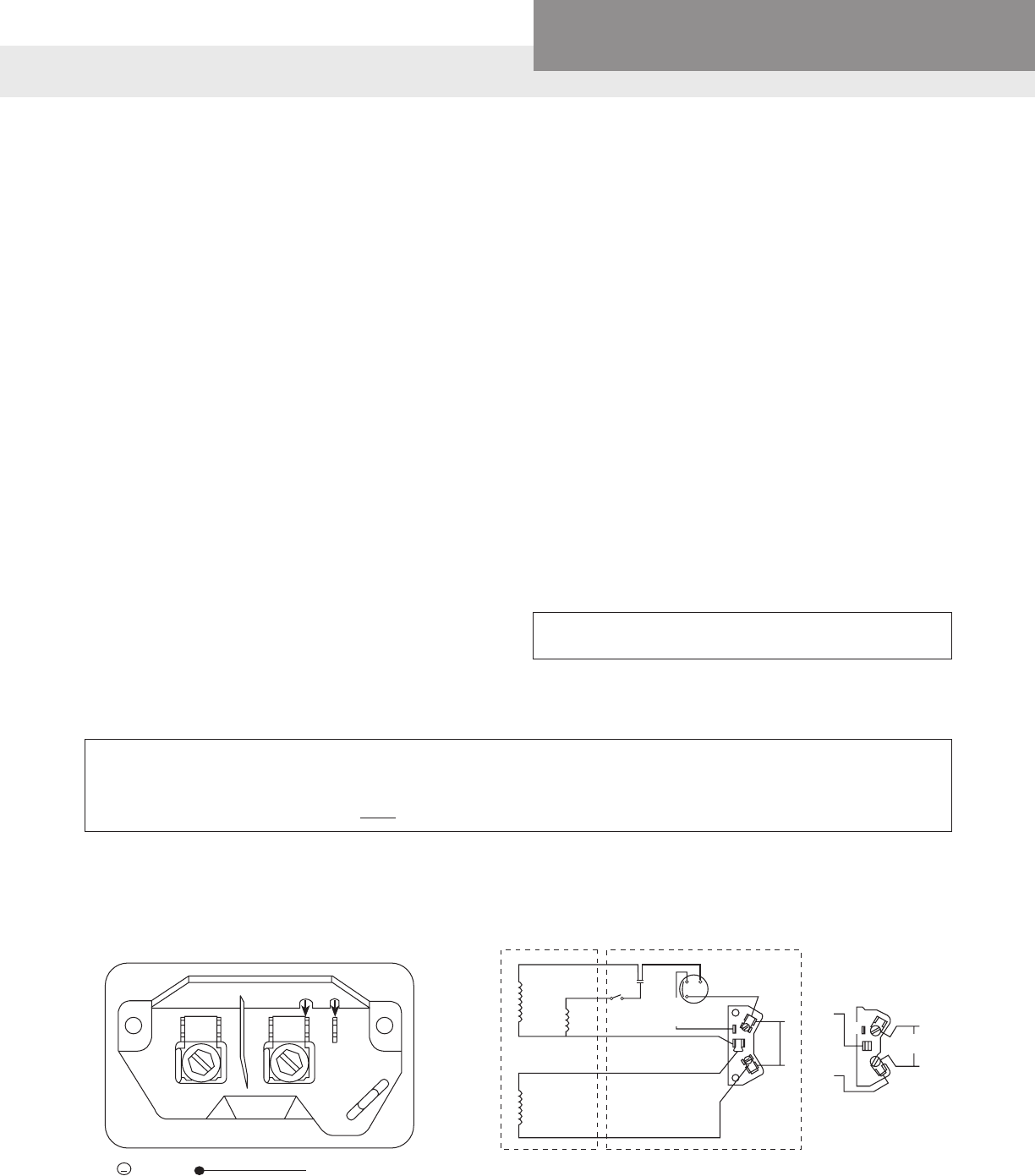
PAGE 56
Residential Water Systems
CentriPro
TERMINAL BOARD AND VOLTAGE CHANGE PLUG
A change has been
made to use a new ter-
minal board on the A.O.
Smith two compartment
motor models. This ter-
minal board is used on
both dual voltage and
single voltage motors.
FEATURES
• Voltage Plug: Dual volt-
age motors use a volt-
age plug that retains
the terminals for the
Black and Black Tracer
leads. To change volt-
age, lift the black plug
and align the arrow
with the desired volt-
age on terminal board.
See Figure 1 for an
example of the dual
voltage connection
diagram.
• Screws with ¼" drive:
The terminal screw
accepts either a ¼"
nut driver or a slotted
screw driver.
• Line Wire Connection:
The space under the
screw will accept #16,
#14, #12, #10, or #8
wire. The rib at the bot-
tom edge of the screw
allows the wire to be
placed straight into the
space under the screw.
This rib retains the wire
under the head of the
screw and for #12, #10,
or #8 wire it is not nec-
essary to wrap the wire
around the screw.
• ½ HP wired 115 V, ¾
HP and up wired 230 V
at factory.
• Quick Connect Termi-
nals: Each terminal has
provision for ¼" quick
connect terminals in
addition to the screw.
• Molded Plastic Ma-
terial: The terminal
board is made from an
extremely tough white
plastic material with
L1, L2, and A markings
molded into the board.
• Lead Channel: A
channel adjacent to
the conduit hole di-
rects wiring to the top
of the board.
• Governor Guard: An
integral backplate pre-
vents leads from enter-
ing the area around
the governor.
• Ground Guard: To
prevent the bare
ground wire from
touching the “live” L2
terminal, the ground
wire must be placed
above this guard.
115 V 230 V
L1 L2
A
FIGURE 1
LINE
GRD Green (Ground)
Align black plug to 115 V or 230 V arrow.
½ HP wired 115 V, ¾ HP and up wired
230 V at factory.
CAPACITOR START INDUCTION RUN –
SINGLE SPEED (OLD STYLE – UP TO APRIL, 1999)
MAINMAIN
PHASE
YELLOW YELLOW
RED
BLACK
PURPLE
WHITE
RED
BLACK TRACER
230 V
L2
L1
L2
L1
A
B
BLACK
TRACER
115 V
L2
L1
A
B
BLACK
TO WIRE FOR 230 V:
BLACK TRACER TO B
BLACK TO A
TO WIRE FOR 115 V:
BLACK TRACER TO A
BLACK TO L1
1
2
3
CAPACITOR START INDUCTION RUN – SINGLE
SPEED (NEW STYLE – AFTER APRIL, 1999)
“Black Tracer” is a black and white wire
VOLTAGE CHANGES ARE MADE INSIDE THE
MOTOR COVER NOT IN THE PRESSURE SWITCH.
JET PUMP MOTOR WIRING A.O. SMITH MOTORS
WARNING:
DISCONNECT POWER SOURCE BEFORE CHECKING. DO NOT MAKE ANY
CHANGES WITH POWER ON.
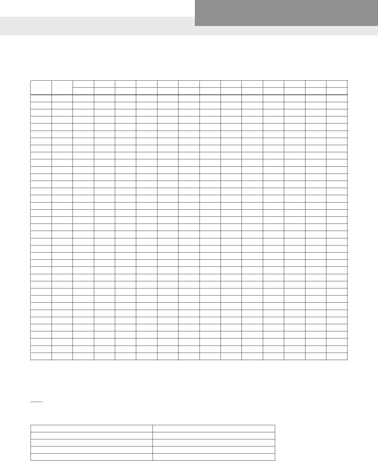
PAGE 57
Residential Water Systems
CentriPro
SCH 40 – PLASTIC PIPE: FRICTION LOSS (IN FEET OF HEAD) PER 100 FT.
GPM GPH 3⁄8" ½" ¾" 1" 1¼" 1½" 2" 2½" 3" 4" 6" 8" 10"
ft. ft. ft. ft. ft. ft. ft. ft. ft. ft. ft. ft. ft.
1 60 4.25 1.38 .356 .11
2 120 15.13 4.83 1.21 .38 .10
3 180 31.97 9.96 2.51 .77 .21 .10
4 240 54.97 17.07 4.21 1.30 .35 .16
5 300 84.41 25.76 6.33 1.92 .51 .24
6 360 36.34 8.83 2.69 .71 .33 .10
8 480 63.71 15.18 4.58 1.19 .55 .17
10 600 97.52 25.98 6.88 1.78 .83 .25 .11
15 900 49.68 14.63 3.75 1.74 .52 .22
20 1,200 86.94 25.07 6.39 2.94 .86 .36 .13
25 1,500 38.41 9.71 4.44 1.29 .54 .19
30 1,800 13.62 6.26 1.81 .75 .26
35 2,100 18.17 8.37 2.42 1.00 .35 .09
40 2,400 23.55 10.70 3.11 1.28 .44 .12
45 2,700 29.44 13.46 3.84 1.54 .55 .15
50 3,000 16.45 4.67 1.93 .66 .17
60 3,600 23.48 6.60 2.71 .93 .25
70 4,200 8.83 3.66 1.24 .33
80 4,800 11.43 4.67 1.58 .41
90 5,400 14.26 5.82 1.98 .52
100 6,000 7.11 2.42 .63 .08
125 7,500 10.83 3.80 .95 .13
150 9,000 5.15 1.33 .18
175 10,500 6.90 1.78 .23
200 12,000 8.90 2.27 .30
250 15,000 3.36 .45 .12
300 18,000 4.85 .63 .17
350 21,000 6.53 .84 .22
400 24,000 1.08 .28
500 30,000 1.66 .42 .14
550 33,000 1.98 .50 .16
600 36,000 2.35 .59 .19
700 42,000 .79 .26
800 48,000 1.02 .33
900 54,000 1.27 .41
950 57,000 .46
1000 60,000 .50
NOTE: See page 5 for website addresses for pipe manufacturers – there are many types of new plastic pipe available now.
FRICTION LOSS
STORAGE OF WATER IN VARIOUS SIZES OF WELLS
D2 = Gallons of Storage per Foot
24.5
Where: D = Inside diameter of well casing in inches
Examples:
2" Casing = .16 Gals. per ft. Storage 8" Casing = 2.6 Gals. per ft. Storage
3" Casing = .36 Gals. per ft. Storage 10" Casing = 4.07 Gals. per ft. Storage
4" Casing = .652 Gals. per ft. Storage 12" Casing = 5.87 Gals. per ft. Storage
5" Casing = 1.02 Gals. per ft. Storage 14" Casing = 7.99 Gals. per ft. Storage
6" Casing = 1.4 Gals. per ft. Storage 16" Casing = 10.44 Gals. per ft. Storage
PAGE 58
Residential Water Systems
CentriPro
UL AND CSA AGENCY LISTING(S)
Our control boxes, motors, complete pump assemblies and electrical accessories are tested by independent
product safety and testing organizations to ensure compliance with the US National Electric Code (NEC) and/
or Canadian Standards Association (CSA) standards. Underwriters Laboratories Inc. and CSA are the agencies
with whom we contract. They have now agreed to eliminate overlapping efforts through an agreement which
allows either to test to the other’s standards. This is good for manufacturers and consumers as overlapping
independent testing is very expensive.
Unfortunately, there is a great deal of misunderstanding associated with the Agency Listings and their marks or
logos. By meeting specic safety requirements products can be either UL Listed or UL Recognized. The UL mark
in a circle signies that a product is UL Listed (approved) for its intended use by Underwriters Laboratories Inc.
Radios, televisions, CD players, fans and small appliances are a good example of UL Listed products.
The lesser known and most misinterpreted UL mark is the backwards , signifying a UL Recognized
Component. This is used on products that are combined to create a complete assembly. In the Submersible
Pump Industry, pumps larger than 2 HP are shipped as separate water ends and motors due to weight and
length restrictions of major shippers. Therefore the products cannot carry a logo, but only the backwards
logo since they are Components of a complete system. According to both UL and CSA, electrical inspectors
should consider the assembled products as approved if the motor and water end are matched by HP, i.e. a ½ HP
Water End on a ½ HP Motor.
The 4” CentriPro motors are tested by Canadian Standards Association to UL 1004 and 2111 as well as to CSA
standards 77 and 100. They carry a logo. This indicates they are CSA Listed for the USA and Canada, i.e.,
tested by C.S.A. to U.L. and CSA standards.
CentriPro, single-phase, 4” motor control boxes carry a listing.
Testing by the Canadian Standards Association is denoted by the CSA logo or .
Per their recent agreement UL can test products sold in the USA and/or Canada, conversely, CSA can test
products sold in Canada and/or the USA.
®
®
UL
®
®
USC
®
USC
®
UL
®
US
C
U
L
®
US
C
PAGE 59
Residential Water Systems
CentriPro
UL
®
C
UL
®
UL
®
USC
®
USC
®
®
®
C
®
USC
US
®
Logos and their meanings follow:
- UL Listed for USA
- UL Listed for Canada (tested by UL to CSA Standards)
- UL Listed for USA and Canada (tested by UL to UL & CSA Standards)
- UL Recognized Component for USA
- UL Recognized Component for Canada (tested by UL to CSA Standards)
- UL Recognized Component for USA and Canada
(tested by UL to UL & CSA Standards)
- CSA approved for Canada
- CSA approved for USA (tested by CSA to UL Standards)
- CSA approved for USA and Canada (tested by CSA to CSA & UL Standards)
- Certied to NSF/ANSI 61, Drinking Water System Components 4P49
- Drinking Water System Components - Certied to NSF/ANSI 61, Annex G
- NSF/ANSI 372 – Drinking Water System Components – Lead Content
CLASS 6853 01 - Low Lead Content Certication Program - - Plumbing Products
California Health and Safety Code 116875 (known as AB-1953-2006)
Vermont Act No. 193 - 2008 - Consumer Products Prohibition against Lead (known as Bill S.152
"An Act Rlating to Prevention of Lead Poisoning by Exposure to Lead in Consumer Products")
Maryland House Bill 372 [Statue 12-605] - Business Occupations and Professionals - Plumbers -
Lead Free Materials
Per the reciprocity agreement between the two agencies, electrical inspectors in both countries should now be
honoring either the UL or CSA mark on products approved for their country.
UL
®
C
L
A
S
S
I
F
I
E
D
WATER QUALITY
®
LLC
NSF/ANSI 61-G
®
TECHNICAL ASSISTANCE AND TROUBLESHOOTING
CUSTOMER SERVICE CONTACT NUMBERS
Four (4") Inch Motors and Controls
Seneca Falls, NY
• Phone: 866-325-4210 — General
• Phone: 866-673-0427 — Technical
• Phone: 866-673-0445 — Controls
• Toll Free Fax: 888-322-5877
Orlando Distribution Center
• Phone: 407-829-7808
• Fax: 407-829-7809
Fresno Distribution Center
• Phone: 559-265-4730
• Fax: 559-265-4740
Southaven, MS (was Memphis)
Distribution Center
• Phone: 662-393-5982
• Toll Free Fax: 800-848-9793
Chicago Customer Service
• Phone: 847-983-5926
• Fax: 847-983-1766
Guelph, Ontario, Canada
• Phone: 519-826-0869
• Fax: 519-826-0874
Six (6") Inch and Larger Motors
Lubbock, Texas Turbine Operation
• Phone: 806-763-7867
• Fax: 800-453-4749
CentriPro is a trademark of Xylem Inc. or one of its subsidiaries.
© 2017 Xylem Inc. BMAID R9 February 2017
Xylem Inc.
2881 East Bayard Street Ext., Suite A
Seneca Falls, NY 13148
www.centripro.com
