RCI PDD FT Power Supply Board Installation Instructions Is10psfpd R0715 1
User Manual: RCI PDD-FT Power Supply Board Installation Instructions Installation Instructions
Open the PDF directly: View PDF ![]() .
.
Page Count: 8

PDD-FT
Fire Panel Interface
With EOL Trigger
Installation and Specifications Manual
PDD-FT
InstallatIon

Details
The PDD-FT board is a fire panel control interface. This board can be used to control DC
output based on a fire alarm control panel. Two outputs switch state on alarm.
Features
• Non Latching or Latching mode
• Universal 12VDC or 24VDC Operation
• Reverse polarity protected
• Normally ON & Normally OFF Output
• Output LED’s indicate condition
• Outputs can be Triggered with:
1) N/O or N/C Switch with Supervised (EOL)
2) N/C Switch with (OVR) over ride
3) N/C Switch with AUX-IN auxiliary
4) Ground on any trigger input when (GRN) Jumper is enabled
• Form C Contacts Indicates Trigger Status
• 12 Amp Transfer Relay Contacts
Installation Instructions
1. Mount the PDD-FT board in a suitable location in close proximity to the power supply.
Note:
a) Ground fault detection will only work if conductive stand offs are used and
power supply enclosure is properly grounded.
b) As this device is used to power multiple devices ensure that all wiring is of an
appropriate gauge for the devices being installed.
c) The RCI PDD-FT board is for use in a controlled environment. Installation
must be in accordance with local building and fire codes. Check with Authority
Having Jurisdiction (AHJ) for details prior to installing.
d) All power limited wiring must be a minimum of .25” from non-power limited
wiring.
2. Connect “INPUT” terminals to output of DC supply, paying close attention to polarity of
DC output from power supply.
3. Connect devices to be powered to output terminals of PDD-FT
control board, paying close attention to polarity requirements.
4. Set jumpers (RST, OVR, AUX, and GRN) as required for proper installation.

5. Connect fire alarm control panel to EOL input terminals, ensure that the 2.2K resistor
is installed at the terminals in the fire alarm panel.
a) See fire alarm control panel installation and operation manual for details about
signaling requirements.
b) Fig’s 2-6 in this installation guide will provide details on wiring to the fire
alarm control panel.
6. Connect any required monitoring equipment to the trouble and trigger relays using
appropriate cabling.
7. The unit is to be powered from the 10 Series power supply or a UL listed
power limited power supply.
8. Apply power to power supply to activate control board and test all connected devices.
Specifications
Note: For UL listed power supply
Input
• Input Voltage: 10.4-13.7 @ 12VDC or 22.7-25.2 @ 24VDC
• Typical Current Draw with no Output Load: 70mA
Output
• 12 VDC nominal, 10.4-13.7 VDC, 5A
24 VDC nominal, 22.7-25.2 VDC, 3A
• 2 Continuous Duty rating: 5A @ 12VDC, 3A @ 24VDC
Note: Total output not to exceed 5A @ 12VDC, 3A @ 24VDC
Monitor Inputs
• EOL (End of Line) Trigger: Trigger at + or – 50% of 2.2K
• OVR Trigger
• AUX Trigger
• Reset Input
• Ground Fault Trigger (see note 1a)
Monitor Outputs
• Trigger Relay Rating: 3A
Environmental
• Product is not for use in outdoor environments
Warning: Improper wiring connections may result in damage to this product.
Mise en garde: Un mauvais raccordement des câbles risque d’endommager ce produit.

Description of PDD-FT Connections
See Fig. 1
Input Power
“-INPUT+”: 2 Pos. Terminal block with self clamping screws will accept multiple 12awg
wires Universal input 10-29VDC. The input current is 70ma to control relays plus whatever
output load is. The positive side of the power is connected to the swing arm of the transfer
relay which directs the power to the proper output.
Output Power
4 Pos. Terminal block Self clamping screws will accept multiple 12awg wires. “-N/ON+” are
normally ON output power. This output is ON when the PDD-FT is not triggered.
“-N/OFF+” is normally OFF. This output is ON when this unit is triggered. The transfer relay
is rated at 15A @ 12VDC and 12A @ 24VDC.
Power LED’s
A red led above each output indicates which output is active.
Input Trigger EOL
2 Pos. Terminal block – Will accept 14-28awg wire. This input must see the 2.2K ohm
end of line resistor to be in the normal set condition. A change in resistance of + or – 60%
will cause the trigger relays to drop out in the Triggered mode. This change in resistance
is caused by the supervised wire between the EOL at the fire panel and the PDD-FT being
shorted or opened. The EOL supervises the pair of wires.
Input Trigger OVR
2 Pos. Terminal block - Will accept 14-28awg wire. This pair is normally closed and can be
connected to an override switch. When OVR is open, unit will trigger.
Input Trigger AUX-IN
2 Pos. Terminal block - Will accept 14-28awg wire. This pair is normally closed and can be
connected to an auxiliary device. When AUX-IN is open, unit will trigger.
Reset 2 Pos. Terminal block
Will accept 14-28awg wire. When this pair is shorted, input triggers do not latch. If pair is
open, the input triggers will latch until alarm is corrected and RESET is momentary closed
to reset trigger.
Jumpers RST - OVR - AUX
Are jumpers with handles to short adjacent terminal blocks that are not used. You may
move the jumper to one header to open short to enable adjacent terminals.
Jumpers GRN
This jumper is used to enable ground supervision in the inputs. If the jumper is connected
to both headers, and the mounting hole adjacent to jumper is connected to ground, a
ground on any of the input triggers will cause a trigger.
Trigger Status Terminal block
Will accept 14-28awg wire. Form C Contact with a 3 Amp rating will indicate the condition
of trigger. C and NO are normally open in the normal energize not triggered state. C and
NC are normally closed in the normal energized not triggered state. These contacts may be
used to provide feedback to the FACP or other annunciating devices.
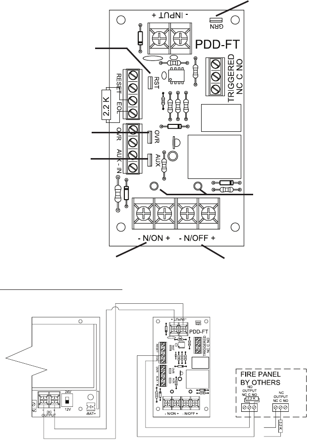
FIG. 1
Application Diagrams
FIG. 2 - Fire Panel Connections for Non-Latching
Automatic Reset Operation
This application illustrates how to connect the PDD-FT to a power supply for main input
as well as a fire alarm control panel. If wired in this manner, outputs will change state only
as long as the fire alarm relay is active. When the fire alarm resets the PDD-FT outputs will
also reset.
Reset Jumper
Overide Jumper
Auxiliary Input
Jumper
Normally “ON” Output Normally “Off” Output
Output LED’s
Ground Fault
Jumper
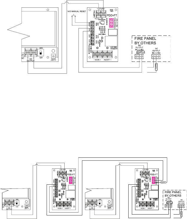
FIG. 3 - Fire Panel Connections for Latching Release with
N/O Manual Reset
This application illustrates how to connect the PDD-FT to a power supply for main input as
well as a fire alarm control panel.
If wired in this manner, outputs will change state whenever the fire alarm relay activates
and remain latched in the triggered state until reset by activating the N/O switch.
Note: Remove RST jumper for manual reset operation.
Remarque: Retirez la bretelle RST pour effectuer une réinitialisation manuelle.
FIG. 4 - Connections for Non-Latching release reset
using multiple PDD-FT boards
This application illustrates how to connect the PDD-FT to a power supply for main input
as well as a fire alarm control panel. If wired in this manner, outputs will change state only
as long as the fire alarm relay is active. When the fire alarm resets the PDD-FT outputs will
also reset. Connecting the EOL input of one board to the trigger relay of the next board as
shown will allow for override and reset of multiple boards.
Note: The RST jumper must be left in place on all boards for automatic reset operation.
Remarque: La bretelle RST doit être laissée en place sur tous les panneaux pour effectuer
une réinitialisation automatique.
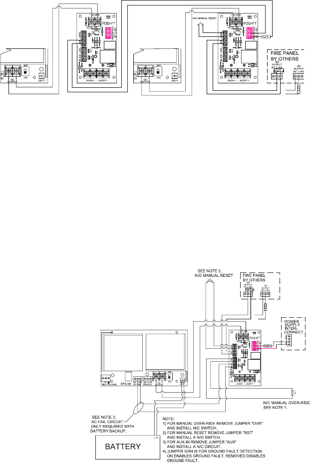
FIG. 5 - Connections for latching release with N/O manual reset using
multiple PDD-FT boards (Master & Slave)
This application illustrates how to connect the PDD-FT to a power supply for main input as
well as a fire alarm control panel. If wired in this manner, outputs will change state when-
ever the fire alarm relay activates and remain latched in the triggered state until the Master
is reset by activating the N/O switch. Connecting the EOL input of one board to the trigger
relay of the next board as shown will allow for override and reset of multiple boards.
Note: The RST jumper must be left in place on all slave boards except the one that is di-
rectly connected to the fire alarm Master, along with reset and override switches.
Remarque: La bretelle RST doit être laissée en place sur tous les panneaux asservis, sauf
celui qui est directement connecté à l’alarme de feu (d’exploitation), situé près des boutons
de réinitialisation et d’annulation.
FIG. 6 - Fire Panel
Connections for Latch-
ing Trigger with N/O
Manual Reset with
Battery Backup
This application illustrates
how to connect the PDD-FT
to an RCI 10-5 for main
input, AC failure as well as
a fire alarm control panel. If
wired in this manner, trigger
outputs will change state
whenever the fire alarm, or
AC failure relays activate. The
PDD-FT outputs will remain
in the triggered state until
both relays have been reset
and the N/O manual reset is triggered.
Note: Ensure jumpers for RST, OVR, and AUX IN are removed to allow terminals to
operate correctly.
Remarque: Assurez-vous que les bretelles RST, OVR et AUX IN sont retirées afin de
permettre aux terminaux de fonctionner correctement.

Notes
___________________________________________
___________________________________________
___________________________________________
___________________________________________
___________________________________________
___________________________________________
For Technical Support:
1-800-265-6630 or 519-621-7651 www.rutherfordcontrols.com
IS10PSFPD PCN15024
R07/15GR-1
PDD-FT Series Troubleshooting Guide
Problem Solution
- Check AC Power.
- Check Power Supply for voltage output.
- Check devices connected to outputs for
a short circuit. (PTC’s may require short
to be removed for several minutes
before automatically resetting).
- Check trigger jumpers. Output LED
should be lit if output is active.
- Check for proper wiring connections on
trigger connections.
- Ensure that 2.2K resistor is installed at
End of Line position in the wiring.
- Check devices connected to outputs for
a short circuit. (PTC’s may require
short to be removed for several minutes
before automatically resetting.)
No DC output from terminals.
Trigger is active and will not reset.
Trouble output relay is de-energized.
(Relay terminals are labeled shown in
the Normal, energized, “no trouble”
condition. Relays are energized when
no trouble is detected.)
© 2015 RutheRFoRD CoNtRolS INt’l | A DoRMA GRouP CoMPANy
www.rutherfordcontrols.com • Phone: 1.800.265.6630 • fax: 1.800.482.9795
• e-mail: sales@rutherfordcontrols.com
