REECON M and E GLDF24RVF Gas Log User Manual 2AJVNGLDF24RVF 1 Rev 1
REECON M & E CO., LTD Gas Log 2AJVNGLDF24RVF 1 Rev 1
Contents
- 1. 2AJVNGLDF24RVF_User Manual 1_Rev 1
- 2. 2AJVNGLDF24RVF_User Manual 2_ Rev 1
- 3. 2AJVNGLDF24RVF_User Manual 3_ Rev 1
2AJVNGLDF24RVF_User Manual 1_Rev 1

WARNING: Do not attempt to access or change the setting of the fuel selection means.
The installer shall replace the access cover before completing the installation and operating this
appliance.
Change of the selector setting to other than the fuel type specified at the time of installation could
damage this appliance and render it inoperable.
Access to and adjustment of the fuel selection means must only be performed by a qualified
service person when connecting this appliance to a specified fuel supply at the time of installation.
Questions,problems? Before returning to your retailer, call our customer service department at
1-877-670-8428, 9:00 am - 6:00 pm EST, Monday through friday or email service@thermablaster.com
This appliance may be installed in an aftermarket, permanently located, manufactured (mobile) home,
where not prohibited by local codes. This appliance is only for use with propane or natural gas. This
appliance is equipped with a simple means to switch between propane and natural gas in dual fuel
models only. Field conversion by any other means including the use of a kit is not permitted.
INSTALLER: Leave this manual with the appliance.
CONSUMER: Retain this manual for future reference.
This is an unvented gas-fired heater. It uses air (oxygen) from the room in which it is installed.
Provisions for adequate combustion and ventilation air must be provided. Refer to Air for
Combustion and Ventilation section on page 8 of this manual.
Warranty is void if not professionally installed.
-- Installation and service must be performed by a qualified installer, service
agency or the gas supplier.
• Do not try to light any appliance
• Do not touch any electrical switch; do not use any phone in your building.
• Immediately call your gas supplier from a neighbor’s phone. Follow the
gas supplier’s instructions.
• If you cannot reach your gas supplier, call the fire department.
-- Do not store or use gasoline or other flammable vapors and liquid in vicinity
of this or any other appliance.
WARNING: IF THE INFORMATION IN THIS MANUAL IS NOT FOLLOWED
EXACTLY, A FIRE OR EXPLOSION MAY RESULT CAUSING PROPERTY
DAMAGE, PERSONAL INJURY, OR LOSS OF LIFE.
CAUTION - FOR YOUR SAFETY
REECON NORTH AMERICA
2515 LIBERTY AVE.
1ST FLOOR
PITTSBURGH, PA 15222
WWW.THERMABLASTER.COM
Conforms to ANS Z21.11-2-2013. Gas-Fired Room Heater Volume II, Unvented Room Heater
24” VENT FREE
GAS LOG
MODEL: GLDF24R-VF

1
Version 1.1A
TABLE OF CONTENTS
About Us………………………….….….…1
Product Specifications……………………1
Important Safety Information…………….2
Product Features………………………….4
Installation Checklist……………………...5
Water Vapor……………………………….7
Air for Combustion…………………….….8
Determining Fresh Air Flow……………...9
Installation Considerations…………………11
Connecting to Gas Supply..........................16
Unit Operation……………………………….18
Care and Maintenance…...........................21
Troubleshooting…………...........................22
Illustrated Parts and Parts List...................25
Service Schedule, Registration
and Contact Information............................27
ABOUT US
We at Reecon strive to produce the highest quality Thermablaster heaters to warm our customers. We
feel that a heater should look as good as it operates and work without a fuss. That is why we have
developed our patent pending dual fuel heating system, which allows the use of either liquid propane or
natural gas for some of our most popular products, without requiring any adjustments. Our product lines
consist of vent free gas wall heaters, a direct vent gas wall heater line, kerosene and propane forced air
heaters, electric industrial heaters, fireplace sets, as well as outdoor heating products. Through our
innovative product design and customer first mentality, we strive to provide the best heaters for all needs,
at a price that won’t break the bank.
PRODUCT SPECIFICATIONS
Model
GLDF24R-VF
Gas type
Using natural gas
Nominal Heat Input
40,000 Btu/hr
Minimum Inlet Supply Pressure (W.C.)
6”
Maximum Inlet Supply Pressure (W.C.)
9”
Manifold Pressure (W.C.)
5.2”
Nominal Input Pressure (W.C.)
7”
Gas type
Using propane gas
Nominal Heat Input
40,000 Btu/hr
Minimum Inlet Supply Pressure (W.C.)
8”
Maximum Inlet Supply Pressure (W.C.)
14”
Manifold Pressure (W.C.)
6”
Nominal Input Pressure (W.C.)
11”
Ignition
Package Dimension (H×W×D)
Heater Dimension (HxWxD)
16.93”x26.57”x17.32”
15.7”x24”x12”
Automatic Ignition
2
IMPORTANT SAFETY INFORMATION
IMPORTANT: Read this owner’s manual
carefully and completely before trying to
assemble, operate, or service this heater.
Improper use of this heater can cause serious
injury or death from burns, fire, explosion,
electrical shock, and carbon monoxide poisoning.
Only a qualified installer, service agent, or local
gas supplier may install and service this product.
WARNING: Do not store or use gasoline
or other flammable vapors and liquids in the
vicinity of this or any other appliance.
CARBON MONOXIDE POISONING: Early signs
of carbon monoxide poisoning resemble the flu
with headache, dizziness and/or nausea. If you
have these signs, heater may not be working
properly. Get fresh air at once! Have heater
serviced. Some people - pregnant women,
persons with heart or lung disease, anemia,
those under the influence of alcohol, those at
high altitude - are more affected by carbon
monoxide than others.
Natural and Propane /LP Gas: Natural and
Propane/LP gas are odorless. An odor-producing
agent is added to the gas. The odor helps you
detect a gas leak. However, the odor added to
the gas can fade. Gas may be present even
though no odor exists.
WARNING: Any change to this heater or its
controls can be dangerous.
WARNING: Do not use any accessories
not approved for use with this heater.
WARNING: Carefully supervise young
children when they are in the room with the
heater.
WARNING: Make sure fireplace screen
must be in place when the appliance is operating
and, unless other provisions for combustion air
are provided, the screen shall have an opening(s)
of introduction of combustion air.
WARNING: Keep the appliance area clear
and free from combustible materials, gasoline,
and other flammable vapors and liquids.
WARNING: Due to high temperatures, the
appliance should be located out of traffic and
away from furniture and draperies.
WARNING: Keep children and adults away
from hot surfaces to avoid burns or clothing
ignition. Heater will remain hot for a time after
shutoff. Allow surfaces to cool before touching.
WARNING: Do not place clothing or other
flammable material on or near the appliance.
Never place any objects in the heater.
WARNING: Failure to keep the primary air
opening(s) of the burner(s) clean may result in
sooting and property damage.
WARNING: Do not allow fans to blow
directly towards the heater. Avoid any drafts that
alter burner flame patterns.
WARNING: Do not use a blower insert,
heat exchanger insert or other accessory not
approved for use with this heater.
WARNING: Failure to position the parts in
accordance with these diagrams or failure to use
only parts specifically approve with this heater
may result in property damage or personal injury.
WARNING: Before installing in a solid-fuel
burning fireplace, the chimney flue and firebox
must be cleaned of soot, creosote, ashes and
loose paint by a qualified chimney cleaner.
Solid-fuel shall not be burned in a fireplace in
which an unvented room heater is installed.
WARNING: Any glass doors shall be fully
opened when the appliance is in operation
CAUTION: Two gas line installations at the same
time are prohibited. The access plate to the

3
switching means shall not be opened while the
heater is in operation.
WARNING: This appliance is for installation
in a solid-fuel burning masonry or UL 127 factory
build fireplace or in a listed vent less firebox
enclosure. It has been design certifies for these
installations. Exceptions: DO NOT install
appliance in a factory build fireplace that includes
instructions stating it has not been tested or
should not be used with unvented gas logs.
1. This heater shall not be installed in a room or
space unless the required volume of indoor
combustion air is provided by the method
described in the National Fuel Gas Code, ANSI
Z223.1/NFPA 54, the International Fuel Gas
Code, or applicable local codes.
2. Do not place Propane/LP supply tank(s) inside
any structure. Propane/LP supply tank(s) must
be placed outdoors.
3. This heater shall not be installed in the place
which the strong wind would shut down the
appliance.
Air ducts and/or ash dumps in the fireplaces shall
be permanently closed at time of appliance
installation.
4. This heater needs fresh air ventilation to run
properly. This heater has an Oxygen Depletion
Sensing (ODS) safety shutoff system. The ODS
shuts down the heater if not enough fresh air is
available. See Air for Combustion and Ventilation,
page 8. If heater keeps shutting off, see
troubleshooting.
5. Keep all air openings in front and bottom of
heater clear and free of debris. This will ensure
enough air for proper combustion.
6. If heater shuts off, do not relight until you have
provided fresh air from outside. If heater keeps
shutting off, have it serviced.
7. Do not run heater where flammable liquids or
vapors are used or stored under dusty
conditions.
8. Before using furniture polish, wax, carpet
cleaner, or similar products, turn heater off. If
heated, the vapors from these products may
create a white powder residue within burner box
or on adjacent walls or furniture.
9. Always run heater with control knob at
PILOT/IGN, LOW or HIGH locked positions.
Never set control knob between locked positions,
otherwise poor combustion and higher levels of
carbon monoxide may be resulted.
10. Do not use this room heater if any part has
been under water. Immediately call a qualified
service technician to inspect the room heater and
to replace any part of the control system and any
gas control which has been under water.
11. Turn off and let heater cool down before
servicing. Only a qualified service person should
service and repair heater.
12. Periodic visual check of pilot and burner
flame, with pictorial sketches or drawings.
13. The appliance must be isolated from the gas
supply piping system by closing its equipment
shut-off valve during any pressure testing of the
gas supply piping system at test pressures equal
to or less than 1/2 psi (3.5 kPa).
Important Note:
An unvented room heater having an input
rating of more than 10,000 Btu/hr (2,931
W) shall not be installed in a bedroom or
bathroom; or
An unvented room heater having an input
rating of more than 6000 Btu/hr (1,758 W)
shall not be installed in a bathroom.

4
QUALIFIED INSTALLING AGENCY
Only a qualified agency should install and replace gas piping, gas utilization equipment or accessories,
repair and service the heater. The term “qualified agency” means any individual, firm, corporation, or
company that either in person or through a representative is engaged in and is responsible for:
a) Installing, testing, or replacing gas piping or
b) Connecting, installing, testing, repairing, or servicing equipment; that is experienced in such work;
that is familiar with all precautions required; and that has complied with all the requirement of the
authority having jurisdiction.
PRODUCT FEATURES
SAFETY PILOT
This heater has a pilot with an Oxygen Depletion Sensing (ODS) safety shutoff system. The ODS/pilot
shuts off the heater if there is not enough fresh air.
AUTOMATIC IGNITION SYSTEM
This heater is equipped with a PCB controlled automatic igniting system. No AC power supply
required. Battery should be periodically checked and replaced accordingly.
GAS OPTIONS CAPABLE (Dual Fuel Models Only) (Models that start with GLDF)
If you have the dual fuel model, your heater is equipped to operate on either propane or natural gas. The
heater will automatically identify your gas source without any manual changes.
THERMOSTATIC CONTROL
These heaters have a control valve with a wireless remote thermostat. This results in the greatest heater
comfort and may result in lower gas bills.
LOCAL CODES
Install and use heater with care. Follow all local codes. In the absence of local codes, use the latest
edition of The National Fuel Gas Code, ANSI Z223.1/ NFPA 54

5
INSTALLATION CHECKLIST
Share this checklist with your professional installer
�Manifold Pressure and Nominal Inlet Pressure for appropriate gas type
oUsing Natural Gas:
Minimum Inlet Pressure (W.C): 6”
Manifold Pressure (W.C.): 5.2”
Nominal Input Pressure (W.C.): 7”
oUsing Propane Gas:
Minimum Inlet Pressure (W.C): 8”
Manifold Pressure (W.C.): 6”
Nominal Input Pressure (W.C.): 11”
�Clearances
o5” minimum from bottom of heater to Top Surface of Floor
o16” Minimum from sides to of Heater
o42” Minimum clearance from top surface of heater and up
�Connected to gas supply using a 5/8
th inch UNF inlet connection to a ½ inch gas pipe
�Unit is placed in a room that is a minimum of 1150 square feet.
�2 pieces of 14500(3.8V)rechargeable batteries placed in heater & AA batteries placed in remote.
�Adequate ventilation and fresh-air flow is appropriate for heater location
�Unit successfully tested
oInstalled by:
Company __________________________________________
�Installer __________________________________________
�Contact Info ________________________________________
�Date ______________________________________________
Note to installer: Ensure that you are referencing the product manual for full details on each of the
installation steps, warnings and considerations. This list is to be used to confirm the steps as you move
through the installation. Please leave this sheet with the user.
*Do not attempt any modifications, repairs or replacements on this unit without first discussing with
Thermablaster Technical Support. Doing so will void the product’s warranty. Professional Installation is
required by all local and National codes.
Unit is not to be used as a central heating system
6
Preparing for Installation
Before beginning assembly or operation of the product, make sure all parts are present. Compare parts
with package contents list and diagram above. If any part is missing or damaged, do not attempt to
assemble, install or operate the product. Contact customer service for replacement parts.
Before installing heater, make sure you have the items listed below:
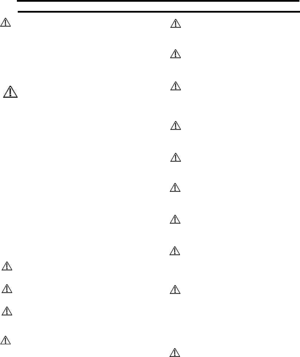
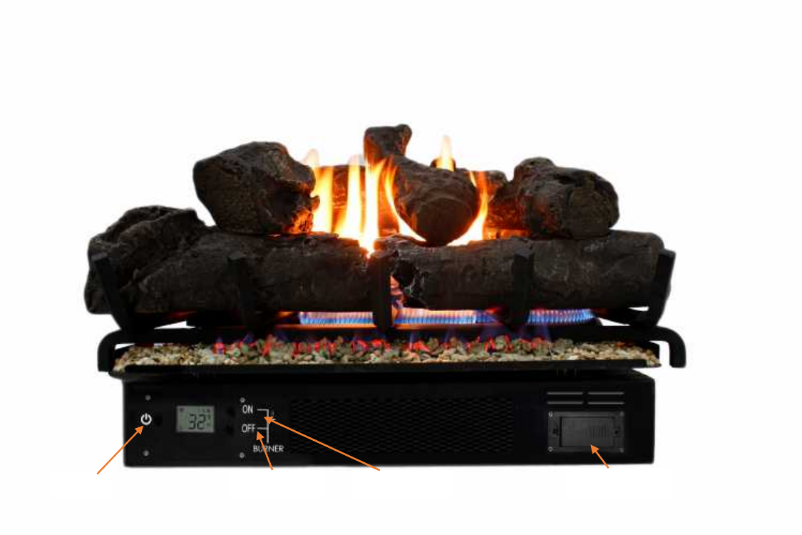
Figure 1 - Vent-Free Gas log
Power
Burner OFF
Burner ON
Battery Cover
7
UNPACKING
1. Remove heater from carton.
2. Remove all protective packaging applied to heater for shipping.
3. Check heater for any shipping damage. If heater is damaged, promptly inform dealer where you
purchased heater.
4. Remove thread protective cup on the gas inlet pipe underneath the heater.
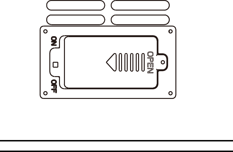
5. Install the two 14500 (3.6V)rechargeable batteries. Be sure batteries
has full capacity.
Batteries must be removed if the heater is not in use for an extended period of time.
Figure 2 – Battery Cover and Power Switch
WATER VAPOR: A BY-PRODUCT OF UNVENTED ROOM HEATERS
Water vapor is a by-product of gas combustion. An unvented room heater produces approximately one (1)
ounce (30 ml) of water for every 1,000 BTUs (0.3 KWs) of gas input per hour. Unvented room heaters are
recommended as supplemental heat (a room) rather than a primary heat source (an entire house). In
most supplemental heat applications, the water vapor does not create a problem. In most applications,
the water vapor enhances the low humidity atmosphere experienced during cold weather. The following
steps will help ensure that water vapor does not become a problem:
1. Be sure the heater is sized properly for the application, including ample combustion air and
circulation air.
2. If high humidity is experienced, a dehumidifier may be used to help lower the water vapor content
of the air.
3. Do not use an unvented room heater as the primary heat source.

8
AIR FOR COMBUSTION AND VENTILATION
WARNING: This heater shall not be
installed in a confined space or unusually
tight construction unless provisions are provided
for adequate combustion and ventilation air.
Read the following instructions to ensure proper
fresh air for this and other fuel-burning
appliances in your home.
Providing Adequate Ventilation
This heater shall not be installed in a room or
space unless the required volume of indoor
combustion air is provided by the method
described in the NATIONAL FUEL GAS CODE,
ANSI Z223.1/NFPA 54, the INTERNATIONAL
FUEL GAS CODE, or applicable local codes.
The following are excerpts from National Fuel
Gas Code, ANSI Z223.1/ NFPA 54. Air for
Combustion and Ventilation. All spaces in homes
fall into one of the three following ventilation
classifications:
1. Unusually Tight Construction
2. Unconfined Space
3. Confined Space
The information on the following pages will help
you classify your space and provide adequate
ventilation.
Confined and Unconfined Space
The National Fuel Gas Code, ANSI
Z223 .1/NFPA 54 defines a confined space as a
space whose volume is less than 50 cu. ft. per
1,000 BTU/hr (4.8 m3 per kw) of the aggregate
input rating of all appliances installed in that
space and an unconfined space as a space
whose volume is not less than 50 cubic feet per
1,000 BTU/hr (4.8 m3 per kw) of the aggregate
input rating of all appliances installed in that
space. Rooms connecting directly with the space
in which the appliances are installed, through
openings not furnished with doors, are
considered a part of the unconfined space.
This heater shall not be installed in a confined
space or unusually tight construction unless
provisions are provided for adequate combustion
and ventilation air. Adjoining rooms are
connecting only if there are odorless
passageways or ventilation grills between them.
Unusually Tight Construction
The air that leaks around doors and windows
may provide enough fresh air for combustion and
ventilation. However, in buildings of unusually
tight construction, you must provide additional
fresh air. Unusually tight construction is defined
as construction where:
a) Walls and ceilings exposed to the outside
atmosphere have a continuous water vapor
retarder with a rating of one perm (6×10-11kg
per pa-sec-m2) or less with openings gasket or
sealed and
b) Weather stripping has been added on
openable windows and on doors and
c) Caulking or sealants are applied to areas such
as joints around window and door frames,
between sole plates and floors, between wall
ceiling joints, between wall panels, at
penetrations for plumbing, electrical, and gas
lines, and at other openings.
If your home meets all of the three criteria above,
you must provide additional fresh air. See
“Ventilation Air from Outdoors”. If your home
does not meet all of the three criteria above,
proceed to “Determining Fresh-Air Flow for
Heater Location”.

9
DETERMINING FRESH-AIR FLOW FOR HEATER LOCATION
Use this worksheet to determine if you have a confined or unconfined space. Space: Includes the room in
which you will install heater plus any adjoining rooms with door less passageways or ventilation grills
between the rooms.
1. Determine the Volume of space in cubic feet
Length X Width X Height = ___________________ cu. Ft.
(Including adjoining rooms with door less passageways or ventilation grills between rooms)
Example: 24’ (L) X 16’ (W) 8’ (H) = 3,072 cu. Ft.
2. Multiply the volume of space by 20 BTU/Hr. to determine the maximum BTU/Hr. the space can
support.
Example: 3.072 cu. Ft. X 20 BTU/Hr. = 61,440 BTU/Hr.
(Maximum BTU/Hr. the room can support)
3. Add the BTU/Hr. of all the fuel burning appliances in the space
Vent Free Heater _________________BTU/Hr.
Gas Appliance #1_________________BTU/Hr.
Gas Appliance #2_________________BTU/Hr.
Example: Vent Free Heater 26,000 BTU/Hr.
Gas Appliance #1 35,000 BTU/Hr.
Total 61,000 BTU/Hr.
The space in the prior example is a confined space because the actual BTU/hr used is more than the
maximum BTU/hr the space can support.
You must provide additional fresh air. Your options are as follows:
Rework worksheet, adding the space of an adjoining room. If the extra space provides an unconfined
space: a) Remove door to adjoining room or add ventilation grills between rooms. See “Ventilation Air
from Inside Building” on next page.
b) Vent room directly to the outdoors. See the following “Ventilation Air from Outdoors” for details.
c) Install a lower BTU/hr heater if lower BTU/hr size makes room unconfined. If the actual BTU/hr
used is less than the maximum BTU/hr the space can support, the space is an unconfined
space. You will need no additional fresh air ventilation.
WARNING: If the area in which the heater may be operated is smaller than that defined as an
unconfined space, or if the building is of unusually tight construction, provide adequate combustion
and ventilation air by one of the methods described in the National Fuel Gas Code, ANSI Z223.1/NFPA
54, Air for Combustion and Ventilation, or applicable local codes.