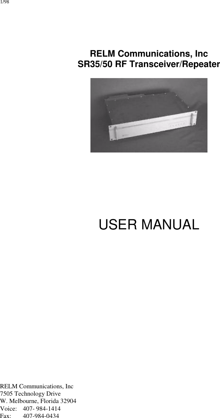
RELM Communications SRU50ABC Repeater User Manual manual
RELM Communications Inc Repeater manual
UserManual.wiki
>
RELM Communications
>
SRU50ABC User Manual
>
manual
Contents
1.
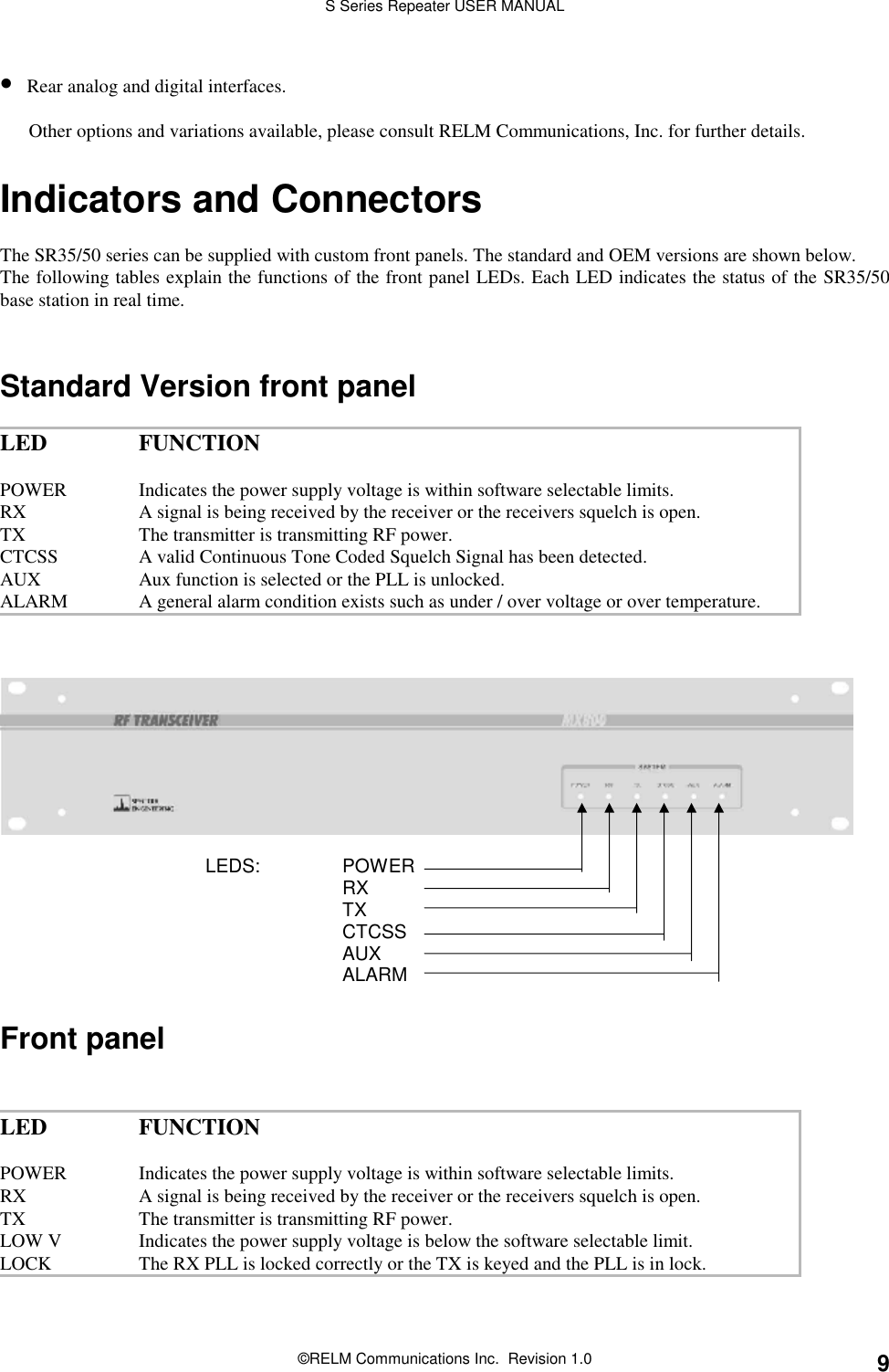
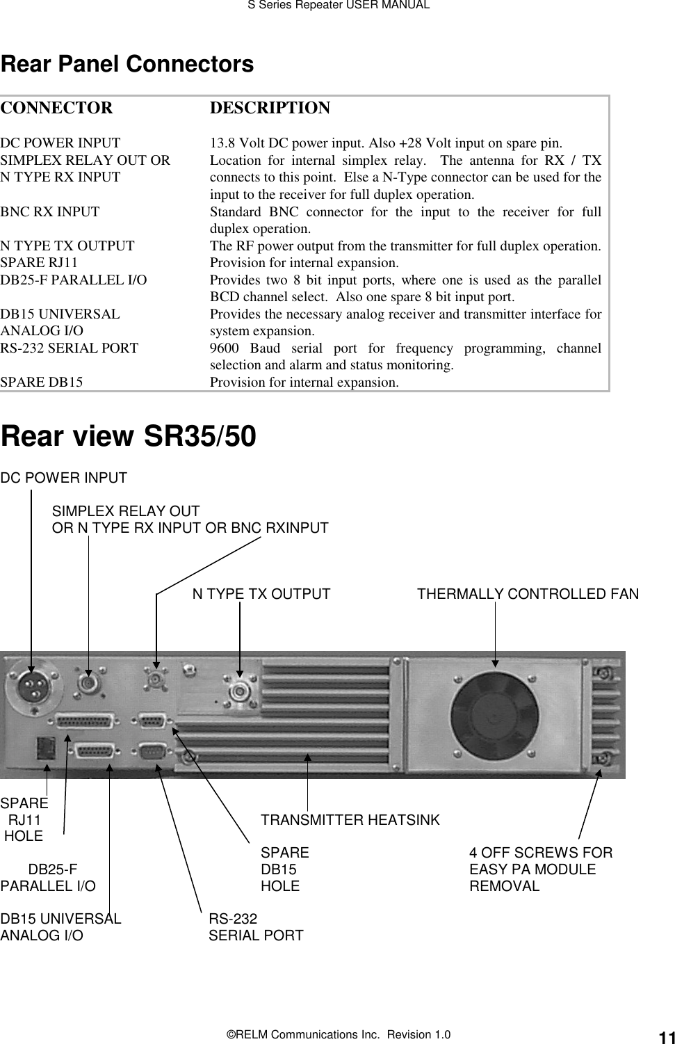
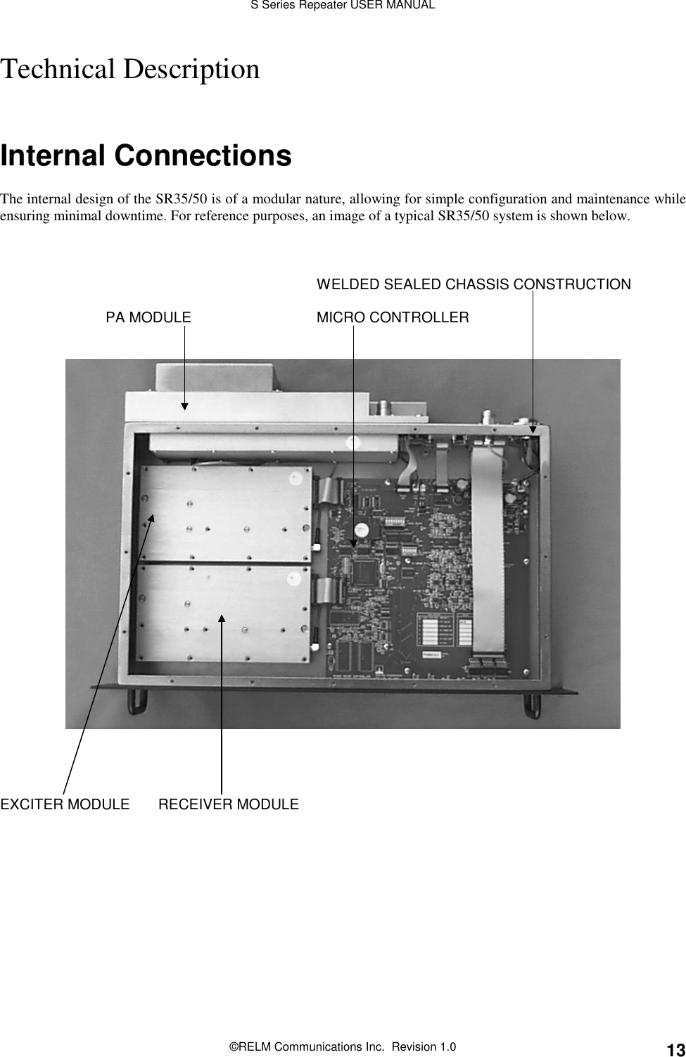
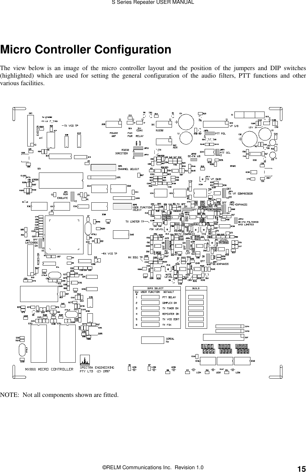
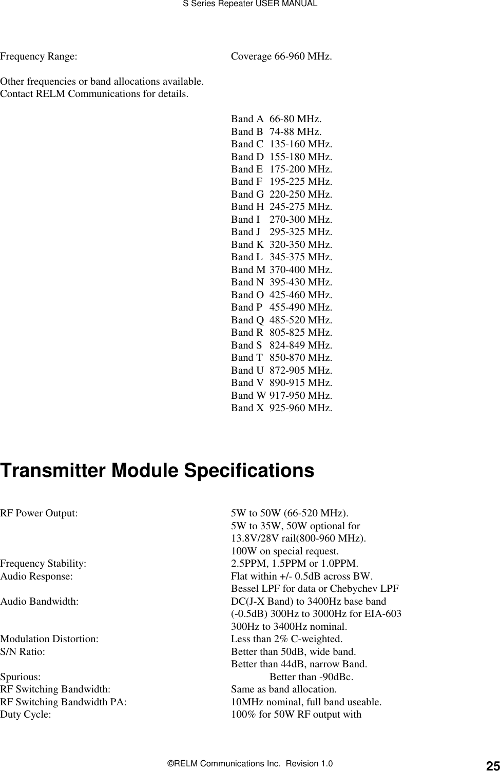
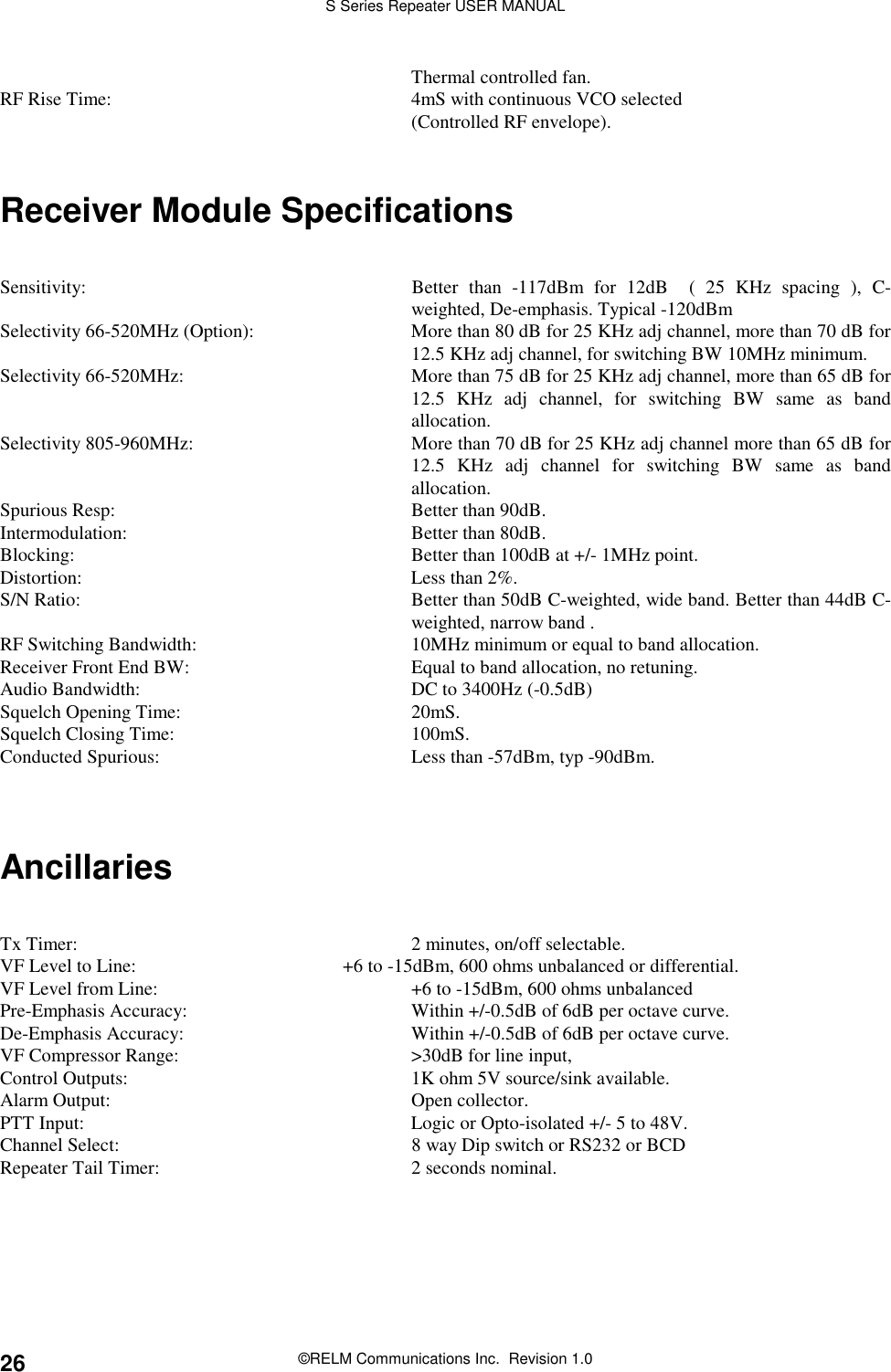
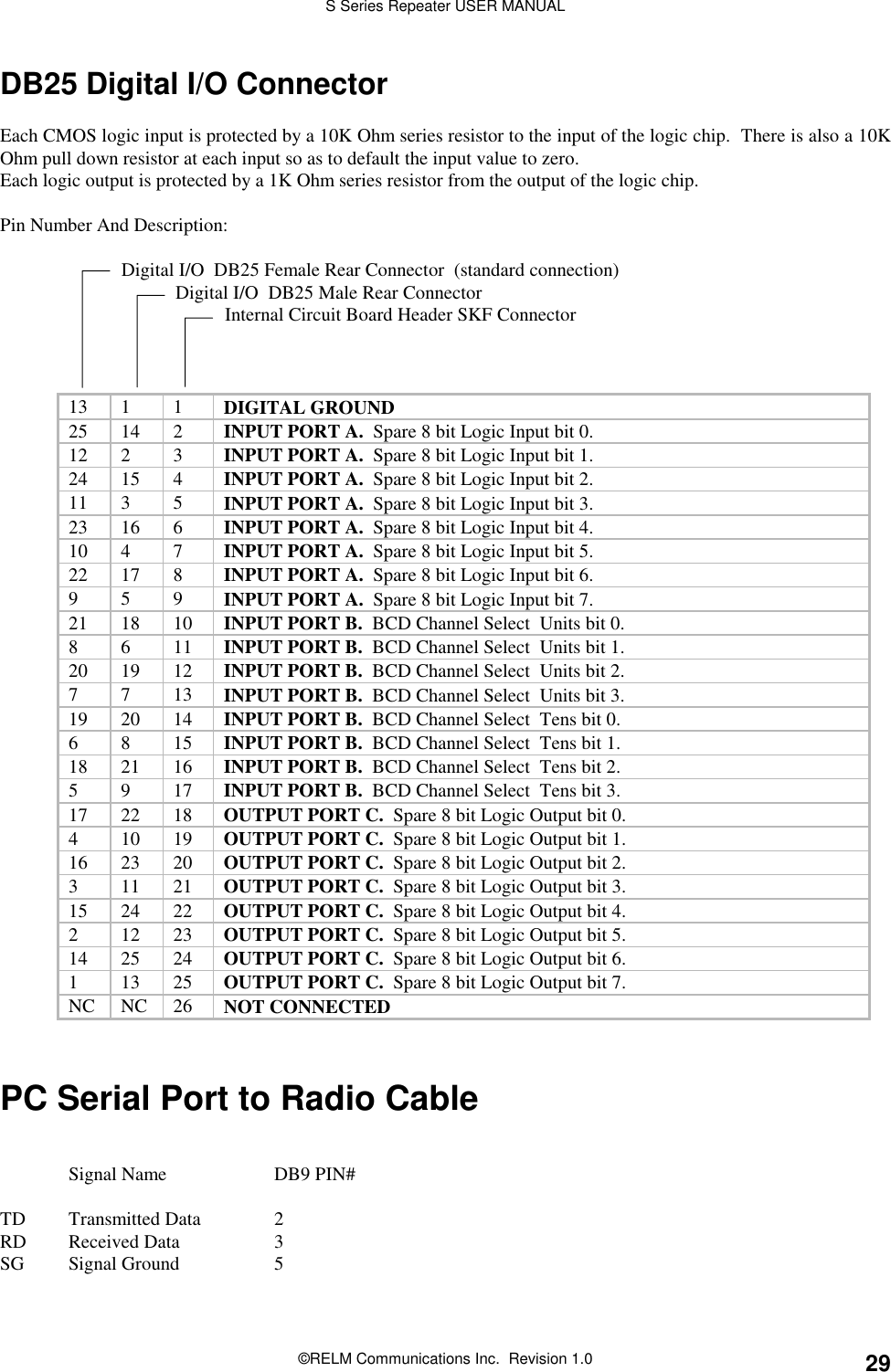
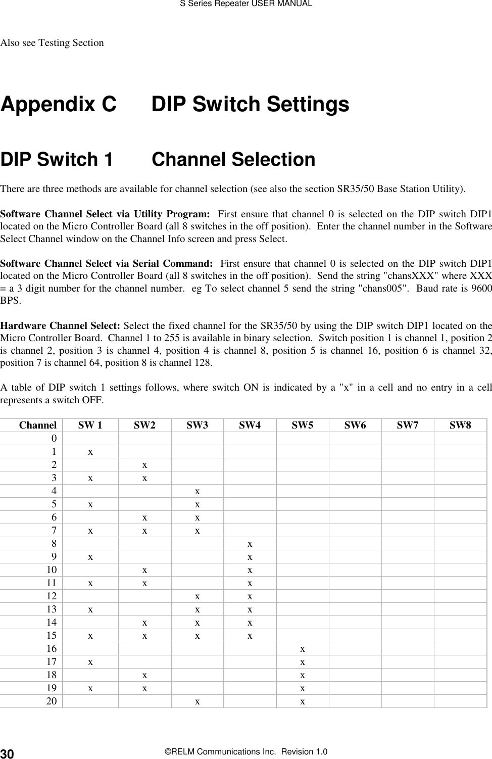
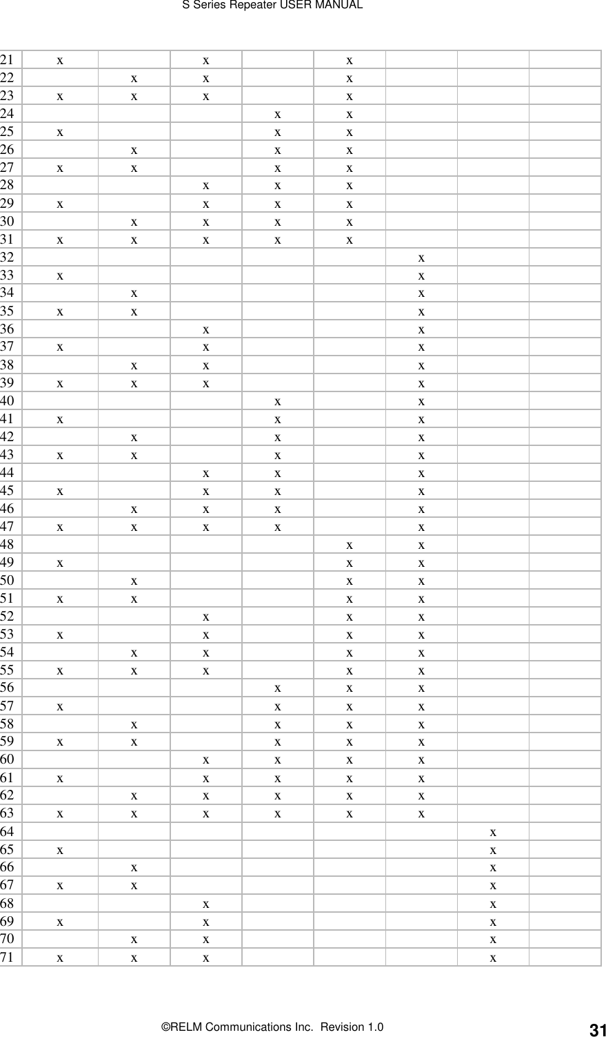
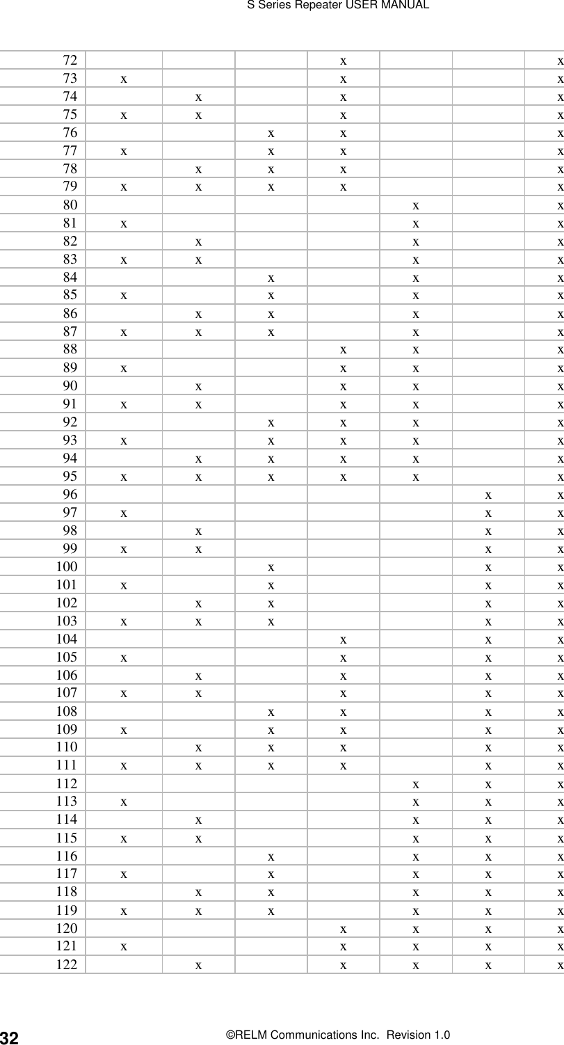
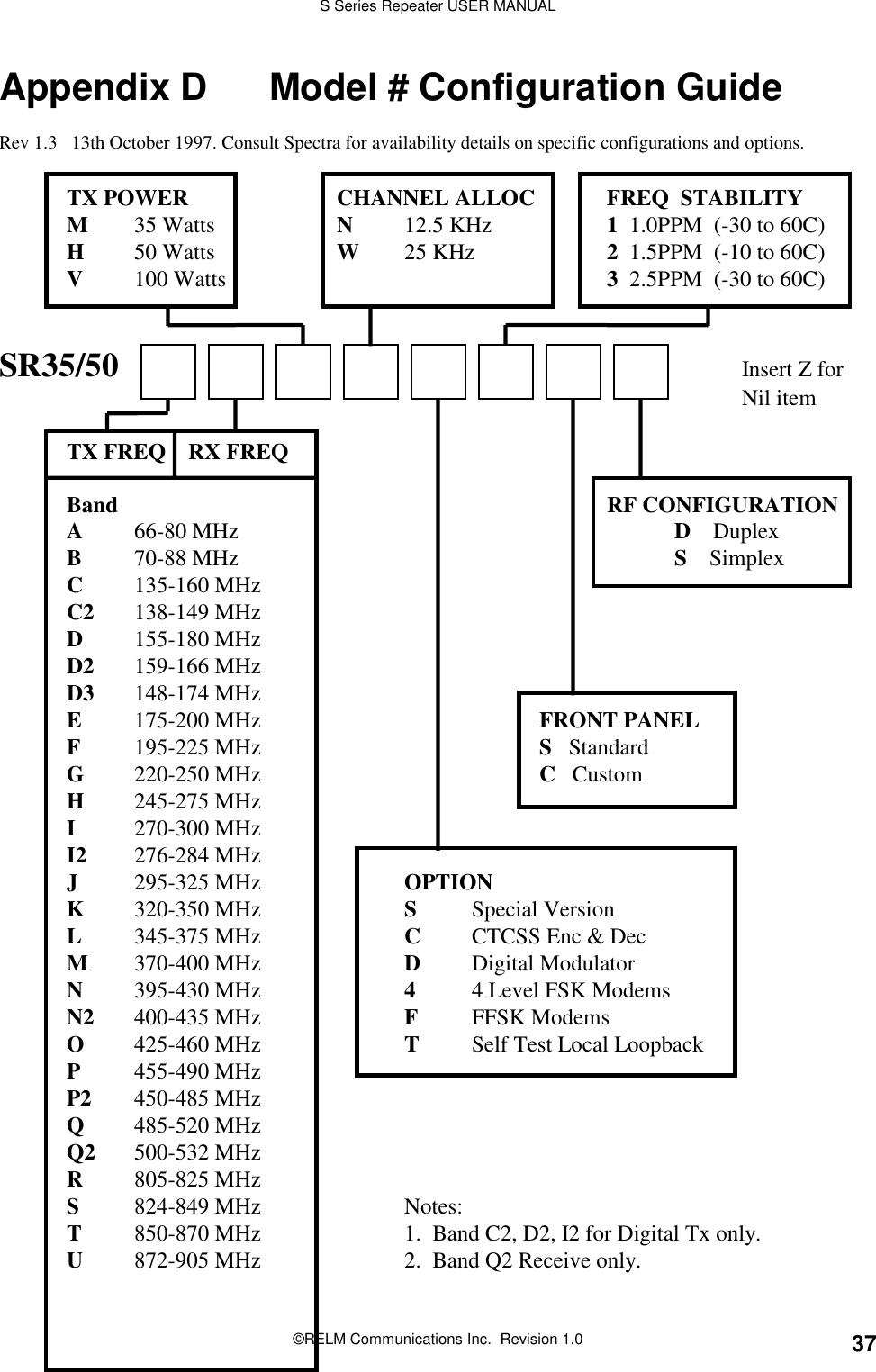
manual
2.
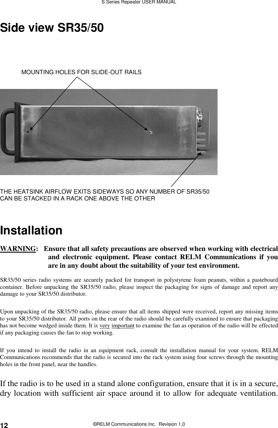
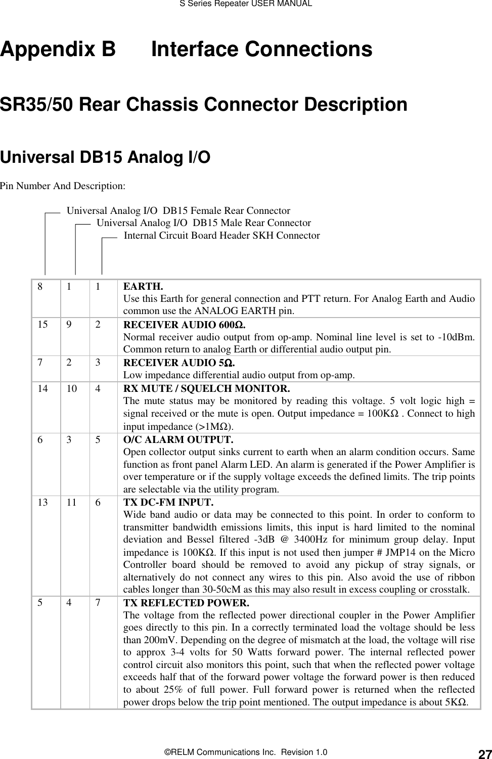
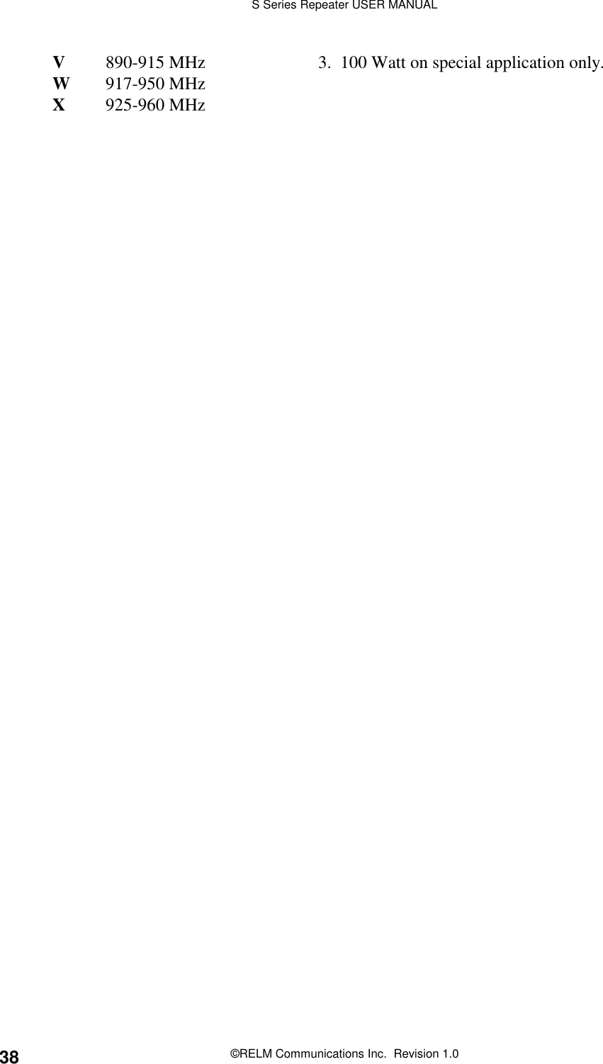
manual pt2
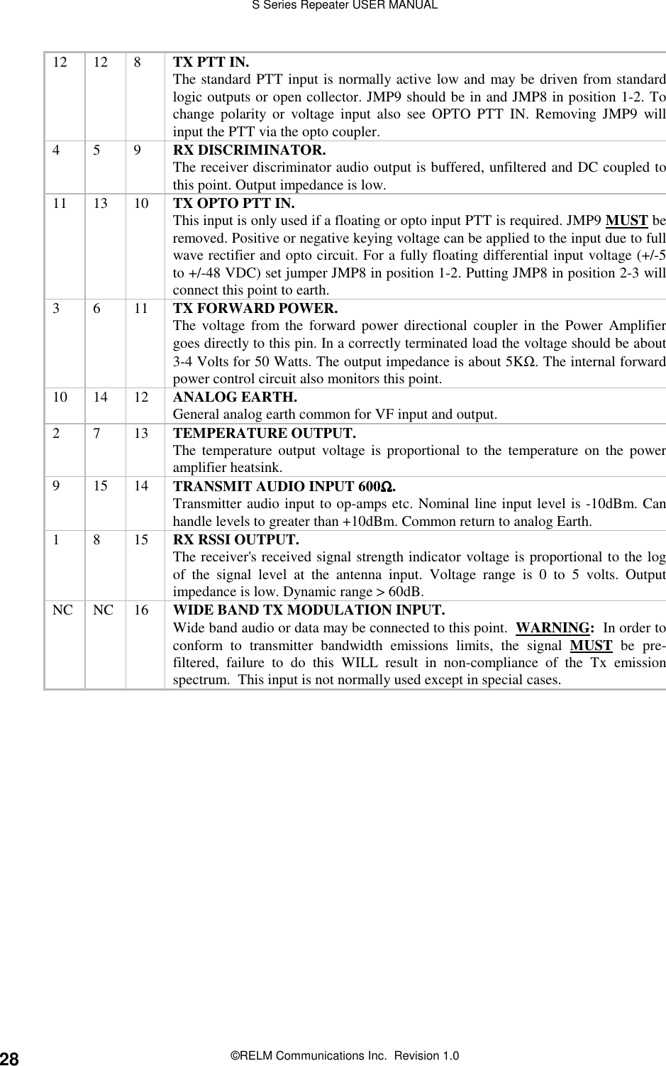
manual
Navigation menu
Upload a User Manual
Namespaces
Wiki Guide
HTML
PDF
Info
Views
User Manual
Discussion / Help
Navigation