ROBOTIS BT-410 Bluetooth User Manual Manual Revision 01

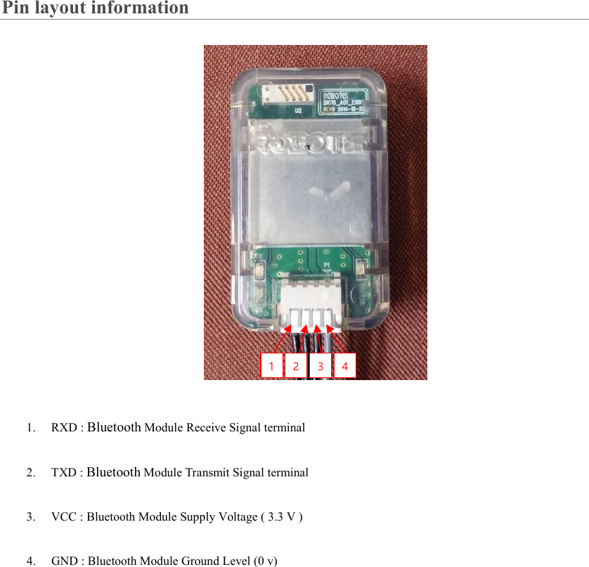
ROBOTIS Bluetooth Manual Revision 01

User Manual

  User Guide   [BT-410]
Purpose The BT-410 is an UART serial Dongle implementing Bluetooth Low Energy standards. The Dongle can be attached to following devices. (Please refer to each controller on how to mount the BT-410.) • BT-410 : CM-100, CM-200, CM-510, CM-530, CM-700, OpenCM9.04  [ examples of use] • DREAM Bug control via Bluetooth communications o Mount the BT-410 to the Bug’s controller (CM-150)   o Connect a smartphone to the BT-410 and control the Bug
Set-up • Install RoboPlus (RoboPlusWeb(v1.1.3.0).exe). • Connect BT-410 to LN-101. • Connect LN-101 to PC via USB port. • Wait during driver installation and COM port assign. • Open Device Manager (My Computer  Properties  Device Manager) • Check COM port number of LN-101. • Run Tera Term.   BT-410 LN-101 --USB --> PC
\
 Setup is now complete. • Go to Setup -> Terminal check Local echo.
• From the terminal after “AT” input press the Enter key. With OK display then connection to BT-410 is successful.  • Instructions types From the terminal it is possible to change or check the status of BT-410 via AT commands. ① System reset ATZ resets the BT-410. Any changes made the command will reset to the change(s) made.  ② Bluetooth device name change Enter AT+BTNAME = to change name
Communications mode • One or multiple BT-410’s can be connected to ONE master module (SmartPhone). LED  • POWER LED • When powered on, the POWER LED will blink; after successful pairing the LED will remain constantly on. • TXD LED • When BT-410 transmits data to controller, TXD LED will blink • RXD LED • When BT-410 receives data from controller, RXD LED will blink TX LED RX LED POWER LED
Pin layout information  1. RXD : Bluetooth Module Receive Signal terminal 2. TXD : Bluetooth Module Transmit Signal terminal   3. VCC : Bluetooth Module Supply Voltage ( 3.3 V ) 4. GND : Bluetooth Module Ground Level (0 v) 1  2  3  4
Hardware characteristics    • weight   o BT-410 : 4.5 g   • size   o BT-410: 18 mm * 30 mm * 9.1 mm   • Bandwidth: MAX 80 kbps • Operating voltage: 3.3 V • Current consumption: 5 mA (MAX)  • Spectrum band frequency: 2.4 GHz ISM Band 1  2  3  4
FCC ID : SOD-BT-410  FCC Information This device complies with part 15 of the FCC Results. Operation is subject to the following two conditions : (1) This Device may not cause harmful interface, and (2) This device must accept any interference received, including interference that may cause undesired operation. Note: This equipment has been tested and found to comply with the limits for CLASS B digital device, pursuant to Part 15 of FCC Rules. These limits are designed to provide reasonable protection against harmful interference when the equipment is operated in a commercial environment This equipment generates, uses and can radiate radio frequency energy and, if not installed and used in accordance with the instructions, may cause harmful interference to radio communications. However, there is no guarantee that interference will not occur in a particular installation. If this equipment does cause harmful interference to radio or television reception, which can be determined by turning the equipment off and on, the user is encouraged to try correct the interference by one or more of the following measures: 1.1. Reorient or relocate the receiving antenna. 1.2. Increase the separation between the equipment and receiver. 1.3. Connect the equipment into an outlet on a circuit different from that to which receiver is connected. 1.4. Consult the dealer or experienced radio/TV technician for help. WARNING Changes or modifications not expressly approved by the manufacturer could void the user’s authority to operate the equipment. “CAUTION : Exposure to Radio Frequency Radiation. Antenna shall be mounted in such a manner to minimize the potential for human contact during normal operation. The antenna should not be contacted during operation to avoid the possibility of exceeding the FCC radio frequency exposure limit.

Navigation menu