Racom RA400-432 UHF NARROWBAND RADIOMODEM User Manual navod RipEX new a
Racom UHF NARROWBAND RADIOMODEM navod RipEX new a
Racom >
Users Manual
User manual
.
RipEX
Radio modem & Router
.
version 1.3
5/31/2012
fw 1.1.4.0
www.racom.eu
RACOM s.r.o. • Mirova 1283 • 592 31 Nove Mesto na Morave • Czech Republic
Tel.: +420 565 659 511 • Fax: +420 565 659 512 • E-mail: racom@racom.eu

Table of Contents
Getting started ..................................................................................................................................... 7
1. RipEX – Radio router ...................................................................................................................... 9
1.1. Introduction ........................................................................................................................... 9
1.2. Key Features ........................................................................................................................ 9
1.3. Standards ........................................................................................................................... 10
2. RipEX in detail ............................................................................................................................... 12
2.1. Modes of operation ............................................................................................................. 12
2.2. Bridge mode ....................................................................................................................... 12
2.3. Router mode ....................................................................................................................... 17
2.4. Serial SCADA protocols ..................................................................................................... 22
2.5. Combination of IP and serial communication ..................................................................... 23
2.6. Diagnostics & network management .................................................................................. 23
2.7. Firmware update and upgrade ........................................................................................... 25
2.8. Software feature keys ......................................................................................................... 25
3. Network planning ........................................................................................................................... 27
3.1. Data throughput, response time ......................................................................................... 27
3.2. Frequency .......................................................................................................................... 28
3.3. Signal budget ..................................................................................................................... 29
3.4. Multipath propagation, DQ ................................................................................................. 30
3.5. Network layout .................................................................................................................... 33
3.6. Hybrid networks .................................................................................................................. 35
3.7. Assorted practical comments ............................................................................................. 35
4. Product .......................................................................................................................................... 37
4.1. Dimensions ......................................................................................................................... 37
4.2. Connectors ......................................................................................................................... 38
4.3. Indication LEDs .................................................................................................................. 43
4.4. Technical specification ........................................................................................................ 44
4.5. Model offerings ................................................................................................................... 52
4.6. Accessories ........................................................................................................................ 53
5. Bench test ..................................................................................................................................... 56
5.1. Connecting the hardware ................................................................................................... 56
5.2. Powering up your RipEX .................................................................................................... 56
5.3. Connecting RipEX to a programming PC ........................................................................... 56
5.4. Basic setup ......................................................................................................................... 60
5.5. Functional test .................................................................................................................... 60
6. Installation ..................................................................................................................................... 61
6.1. Mounting ............................................................................................................................. 61
6.2. Antenna mounting .............................................................................................................. 64
6.3. Antenna feed line ............................................................................................................... 64
6.4. Grounding ........................................................................................................................... 65
6.5. Connectors ......................................................................................................................... 65
6.6. Power supply ...................................................................................................................... 65
7. Advanced Configuration ................................................................................................................ 66
7.1. Menu header ...................................................................................................................... 66
7.2. Status ................................................................................................................................. 67
7.3. Settings ............................................................................................................................... 68
7.4. Routing ............................................................................................................................... 98
7.5. Diagnostic ......................................................................................................................... 100
7.6. Maintenance ..................................................................................................................... 113
8. CLI Configuration ........................................................................................................................ 117
9. Troubleshooting ........................................................................................................................... 118
3© RACOM s.r.o. – RipEX Radio modem & Router

10. Safety, environment, licensing ................................................................................................... 120
10.1. Frequency ...................................................................................................................... 120
10.2. Safety distance ............................................................................................................... 120
10.3. High temperature ............................................................................................................ 125
10.4. RoHS and WEEE compliance ........................................................................................ 125
10.5. Conditions of Liability for Defects and Instructions for Safe Operation of Equipment .... 126
10.6. Important Notifications .................................................................................................... 126
10.7. Product Conformity ......................................................................................................... 127
A. Abbreviations .............................................................................................................................. 129
Index ................................................................................................................................................ 131
B. Revision History .......................................................................................................................... 133
List of Figures
1. RipEX radio router ........................................................................................................................... 7
2.1. Bridge mode example ................................................................................................................ 15
2.2. Addressing ................................................................................................................................. 20
2.3. Optimised addressing ................................................................................................................. 21
2.4. Monitoring ................................................................................................................................... 25
3.1. Application bench test ................................................................................................................ 28
3.2. Signal path ................................................................................................................................. 29
3.3. Multipath propagation ................................................................................................................. 31
3.4. Antenna location ......................................................................................................................... 32
3.5. Main lobe .................................................................................................................................... 33
3.6. Dominant repeater ...................................................................................................................... 34
3.7. Isolated branches ....................................................................................................................... 34
3.8. Antenna mounting ...................................................................................................................... 36
4.1. RipEX dimensions, see more ..................................................................................................... 37
4.2. L-bracket and Flat-bracket, see more ........................................................................................ 37
4.3. Connectors ................................................................................................................................. 38
4.4. Antenna connector TNC ............................................................................................................. 38
4.5. Separated Rx and TX antennas ................................................................................................. 39
4.6. Supply connector ........................................................................................................................ 40
4.7. Power and Control - cable plug .................................................................................................. 40
4.8. RJ-45F ........................................................................................................................................ 41
4.9. Serial connector ......................................................................................................................... 41
4.10. Serial connector ....................................................................................................................... 42
4.11. Reset ........................................................................................................................................ 42
4.12. GPS Connector SMA ............................................................................................................... 42
4.13. Indication LEDs ........................................................................................................................ 43
4.14. Part Number ............................................................................................................................. 52
4.15. Assembly dimensions with fan ................................................................................................. 53
4.16. Dummy load ............................................................................................................................. 53
4.17. L-bracket .................................................................................................................................. 53
4.18. Flat bracket ............................................................................................................................... 54
4.19. 19" Rack shelf .......................................................................................................................... 54
4.20. X5 adapter ETH/USB ............................................................................................................... 54
4.21. Demo case ............................................................................................................................... 55
5.1. Bench test .................................................................................................................................. 56
5.2. Connecting to a PC over ETH and over ETH/USB adapter ....................................................... 57
5.3. PC address setting ..................................................................................................................... 58
5.4. Authentication ............................................................................................................................. 59
RipEX Radio modem & Router – © RACOM s.r.o.4
RipEX
Radio modem & Router

5.5. Status Menu ............................................................................................................................... 59
6.1. Flat lengthwise mounting to DIN rail – recommended ............................................................... 61
6.2. Flat widthwise mounting to DIN rail ............................................................................................ 61
6.3. Vertical widthwise mounting to DIN rail ...................................................................................... 62
6.4. Vertical lengthwise mounting to DIN rail ..................................................................................... 62
6.5. Flat mounting using Flat bracket ................................................................................................ 62
6.6. Rack shelf ................................................................................................................................... 63
6.7. Fan kit mounting ......................................................................................................................... 63
6.8. Fan kit using Alarm Output, recommended ................................................................................ 64
6.9. Fan kit, always on ....................................................................................................................... 64
6.10. 10–30 VDC Supplying .............................................................................................................. 65
7.1. Menu Header .............................................................................................................................. 66
7.2. Menu Status ............................................................................................................................... 67
7.3. Menu Settings ............................................................................................................................ 68
7.4. Menu Alarm management .......................................................................................................... 73
7.5. Menu Radio ................................................................................................................................ 76
7.6. Menu Ethernet ............................................................................................................................ 79
7.7. Menu COM ................................................................................................................................. 84
7.8. Menu Protocols COM ................................................................................................................. 86
7.9. Menu Routing ............................................................................................................................. 98
7.10. Menu Neighbours ................................................................................................................... 100
7.11. Menu Statistic ......................................................................................................................... 103
7.12. Menu Graphs .......................................................................................................................... 104
7.13. Menu Ping .............................................................................................................................. 105
7.14. Menu Monitoring ..................................................................................................................... 109
7.15. Monitoring ............................................................................................................................... 113
7.16. Menu SW feature keys ........................................................................................................... 113
7.17. Menu Maintenance Configuration .......................................................................................... 114
7.18. Menu Maintenance Firmware ................................................................................................. 115
7.19. Menu Maintenance Password ................................................................................................ 115
7.20. Menu Maintenance Configuration .......................................................................................... 116
10.1. RipEX consistency declaration ............................................................................................... 128
List of Tables
4.1. Pin assignement ......................................................................................................................... 39
4.2. Ethernet to cable connector connections ................................................................................... 41
4.3. COM1,2 pin description .............................................................................................................. 41
4.4. USB pin description .................................................................................................................... 42
4.5. Key to LEDs ............................................................................................................................... 43
4.6. Technical parameters ................................................................................................................. 44
4.7. Channel spacing 25 kHz, exponential modulation, CE .............................................................. 47
4.8. Channel spacing 25 kHz, linear modulation, CE ........................................................................ 47
4.9. Channel spacing 12,5 kHz, exponential modulation, CE ........................................................... 48
4.10. Channel spacing 12,5 kHz, linear modulation, CE ................................................................... 48
4.11. Channel spacing 25 kHz, exponential modulation, FCC .......................................................... 49
4.12. Channel spacing 25 kHz, linear modulation, FCC ................................................................... 49
4.13. Channel spacing 12,5 kHz, exponential modulation, FCC ....................................................... 50
4.14. Channel spacing 12,5 kHz, linear modulation, FCC ................................................................ 50
4.15. Channel spacing 6,25 kHz, exponential modulation, FCC ....................................................... 51
4.16. Channel spacing 6,25 kHz, linear modulation, FCC ................................................................ 51
10.1. Minimum Safety Distance 160 MHz ....................................................................................... 120
5© RACOM s.r.o. – RipEX Radio modem & Router
RipEX
Radio modem & Router

10.2. Minimum Safety Distance 300–400 MHz ............................................................................... 122
RipEX Radio modem & Router – © RACOM s.r.o.6
RipEX
Radio modem & Router
Getting started
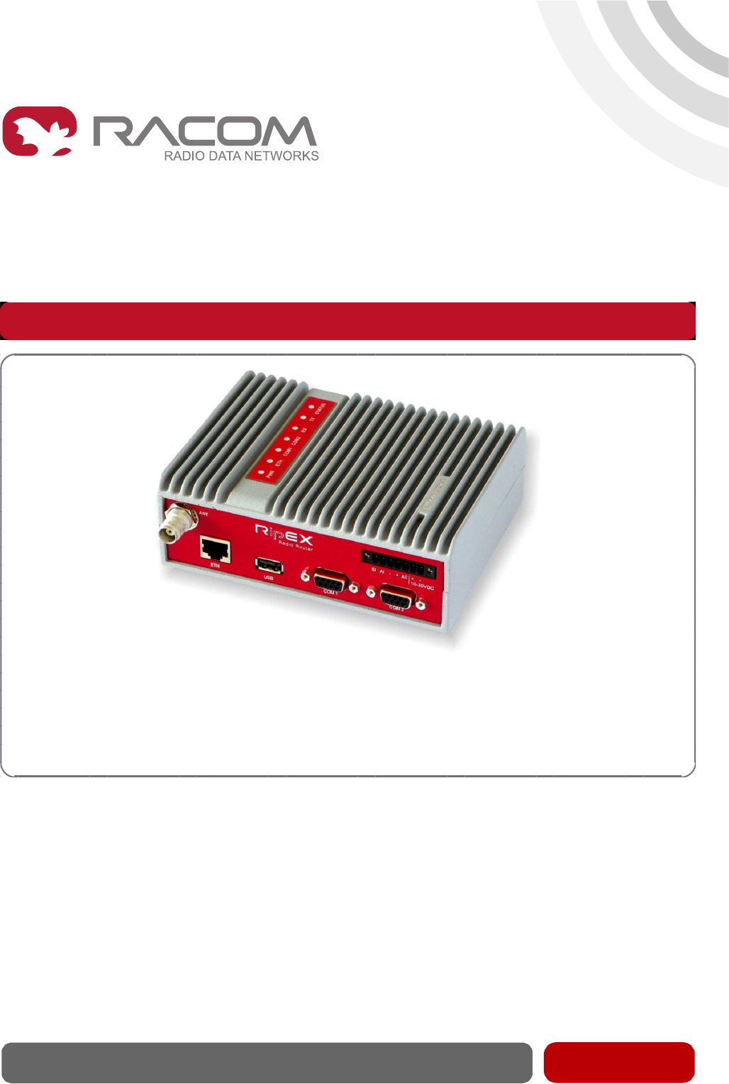
RipEX is a widely configurable compact radio modem, more precisely a radio IP router. All you have
to do to put it into operation is to connect it to an antenna and a power supply and configure it using a
PC and a web browser.
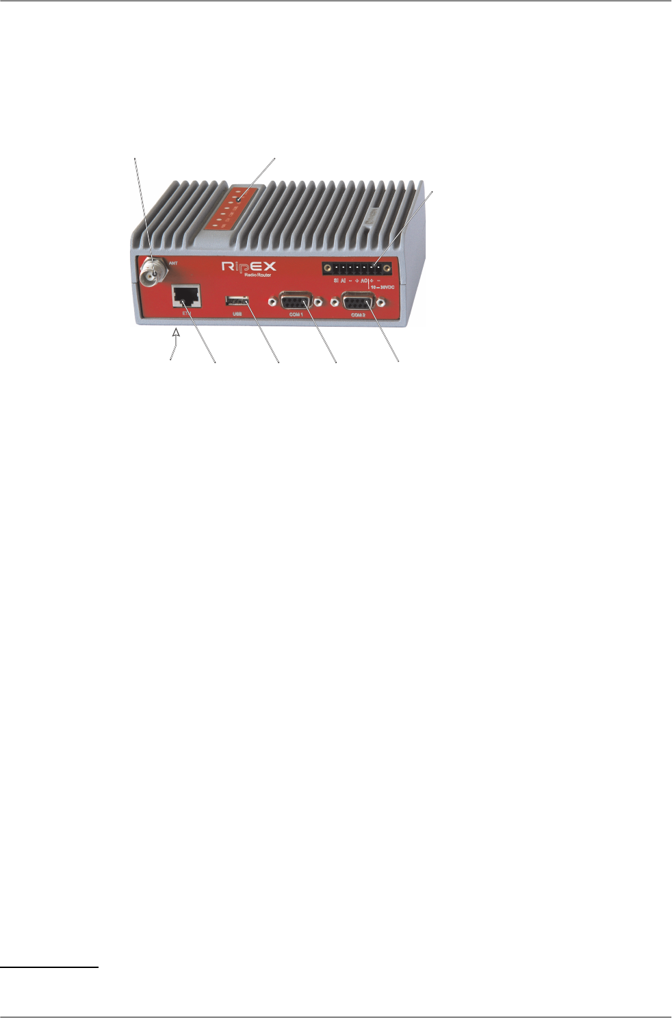
Antenna IndicatorLEDs' SleepInput
AlarmInput
-GND
+
AlarmOutput
+Supply+10to+30V
-GND
Ethernet USB
COM1
RS232
COM2
RS232/485
Default/Reset
-
-++
SI AI
AO
10–30VDC
ETH USB
ANT
COM1
COM2
Fig. 1: RipEX radio router
RipEX access defaults: IP 192.168.169.169/24, username: admin, password: admin
Set a static IP 192.168.169.x/24 on your PC, power on the RipEX and wait 25 seconds for the RipEX
OS to boot. Connect your PC to RipEXs' ETH interface, start your browser and type ht-
tps://192.168.169.169 in the address line. When accessing RipEX for the first time, you have to accept
the https security certificate issued by Racom.
Before attempting to do any configuration, make sure your RipEX is the only powered-up unit around.
Since all units coming from factory share the same default settings ex factory, you could be accessing
a different unit over the air without being aware of it.
When accessing over the optional “X5” USB/ETH adapter, your PC will get its IP settings from the built-
in DHCP server and you have to type https://10.9.8.7 in your browser. Remaining steps are the same
and you do not need to worry about other RipEX's, you will be connected to the local unit in all cases.
SCADA radio network step-by-step
Building a reliable radio network for a SCADA system may not be that simple, even when you use such
a versatile and easy-to-operate device as the RipEX radio modem. The following step-by-step checklist
can help you to keep this process fast and efficient.
1. Design your network to ensure RF signal levels meet system requirements.
2. Calculate and estimate the network throughput and response times when loaded by your application.
3. Perform a bench-test with 3-5 sets of RipEX's and SCADA equipment (Chapter 5, Bench test).
4. Design the addressing and routing scheme of the network (Chapter 2, RipEX in detail and RipEX
App notes, Address planing1)
5. Preconfigure all RipEX's (Section 5.4, “Basic setup”).
6. Install individual sites
1. Mount RipEX into cabinet (Section 6.1, “Mounting”).
1http://www.racom.eu/eng/products/m/ripex/app/routing.html
7© RACOM s.r.o. – RipEX Radio modem & Router
Getting started

2. Install antenna (Section 6.2, “Antenna mounting”).
3. Install feed line (Section 6.3, “Antenna feed line”).
4. Ensure proper grounding (Section 6.4, “Grounding”).
5. Run cables and plug-in all connectors except from the SCADA equipment (Section 4.2,
“Connectors”)
6. Apply power supply to RipEX
7. Test radio link quality (Section 5.5, “Functional test”).
8. Check routing by the ping tool (the section called “Ping”) to verify accessibility of all IP ad-
dresses with which the unit will communicate.
9. Connect the SCADA equipment
7. Test your application
RipEX Radio modem & Router – © RACOM s.r.o.8
Getting started

1. RipEX – Radio router
1.1. Introduction
RipEX is a best-in-class radio modem, not only in terms of data transfer speed. This Software Defined
Radio with Linux OS has been designed with attention to detail, performance and quality. All relevant
state-of-the-art concepts have been carefully implemented.
RipEX provides 24x7 reliable service for mission-critical applications like SCADA & Telemetry for Util-
ities, SmartGrid power networks or transaction networks connecting lottery terminals, POS or ATM’s.
Any unit can serve as the central master, repeater, remote terminal, or all of these simultaneously, with
a configuration interface easily accessible from a web browser.
Anybody with even basic knowledge of IP networking can set up a RipEX within a matter of minutes
and maintain the network quite easily.
1.2. Key Features
• Exceptional data speeds on the radio channel
- 83 kbps / 25 kHz, 42 kbps / 12.5 kHz, 21 kbps / 6.25 kHz
• 1× ETH, 2× COM, 1× USB, 5× virtual COM
- Simultaneously on radio channel. COM1-RS232, COM2-RS232 or RS485, software configurable.
Virtual COMs over ETH controlled by Terminal servers. USB for independent service access via
USB/ETH adapter.
• 135–175; 300–370; 368–470; 928–960 MHz
- Licensed radio bands
- Software-selectable channel spacing 25, 12.5 or 6.25 kHz
• 10 watts
- Transmission output control, nine stages from 0.1 to 10 W (max. 2 W for linear modulations).
• Energy saving
- Sleep mode – 0.1 W, controlled via a digital input.
Save mode – 2.3 W, wake up by receiving a packet from the radio channel
• Extended temperature range
−40 to +70 ºC
• Easy to configure and maintain
- Web interface,
- Wizards,
- On-line help,
- Balloon tips,
- Fastest web access to remote units
• Bridge or Router
- RipEX is a device with native IP support which can be set as a standard bridge or router.
9© RACOM s.r.o. – RipEX Radio modem & Router
RipEX – Radio router

• Modbus, IEC101, DNP3, Comli, RP570, C24, DF1, Profibus, Modbus TCP, IEC104, DNP3 TCP
etc.
- Unique implementation of industrial protocols enables a secure addressed transmission of all
packets in all directions
• Anti-collision protocol on radio channel
- Allows multi polling & report-by-exception concurrently for several independent applications sim-
ultaneously
• Optimization – 3× higher throughput
- Optimisation method which joins short packets, compresses data, optimises both the traffic to the
link peer and the sharing of the radio channel capacity among the links.
• Embedded diagnostic & NMS
- Real time and historical (20 periods, e.g. days) statistics and graphs for the unit and its neighbours.
- SNMP including generation of TRAP alarms when preset thresholds are exceeded
- on-line/off-line (recorded to a file in the RipEX) monitoring of all interfaces
• 256 AES encryption
- The most secure encryption meets FIPS 140 2 requirements
• Pay only for what you need
- Software authorisation keys allow you to add advanced features when needed (Router mode, 83
kbps, COM2, 10 W)
- Free Master-key trial – (all coded features) for 30 days in every RipEX
• Reliability
- 3 years warranty, rugged die cast aluminium case, military or industrial components
- Every single unit tested in a climatic chamber as well as in real traffic
1.3. Standards
ETSI EN 300 113-2Radio
ETSI EN 302 561
ETSI EN 301 166-2
FCC part 90
ETSI EN 301 489-1EMC
ETSI EN 301 489-5
ETSI EN 301 489-5
EN 61000-3-2
EN 61000-3-3
EN 60 950-1Safety
EN 61 373Vibration
IEEE 802.3iETH
IEEE 802.3u
IEEE 802.3af
RipEX Radio modem & Router – © RACOM s.r.o.10
RipEX – Radio router

EIA-232-FRS232
EIA RS-485RS485
IEC 60870-5-101IEC101
IEC 60870-5-104IEC104
IEEE 1815-2010DNP3
IEC 61158 Type 3Profibus DP-V0
11© RACOM s.r.o. – RipEX Radio modem & Router
RipEX – Radio router

2. RipEX in detail
2.1. Modes of operation
Radio modem RipEX is best suited for transmission of a large number of short messages where a
guaranteed delivery time is required, i.e. for mission critical applications.
RipEX has the following basic uses:
• Polling
In poll-response networks a central master unit communicates with a number of remote radiomodems
one at a time. The master unit exchanges data with the currently connected remote radio, and when
finished, it establishes a new connection with the next remote radio according to the polling order.
• Report-by-exception
In report-by-exception networks remote units can be contacted similarly to polling networks. In ad-
dition, any remote unit can spontaneously send data to the master unit (typically an alarm).
• Mesh
In mesh type networks any radio modem in the network can access any other radio modem randomly
and spontaneously. Mesh network can also host polling or report-by-exception applications, even
in several instances.
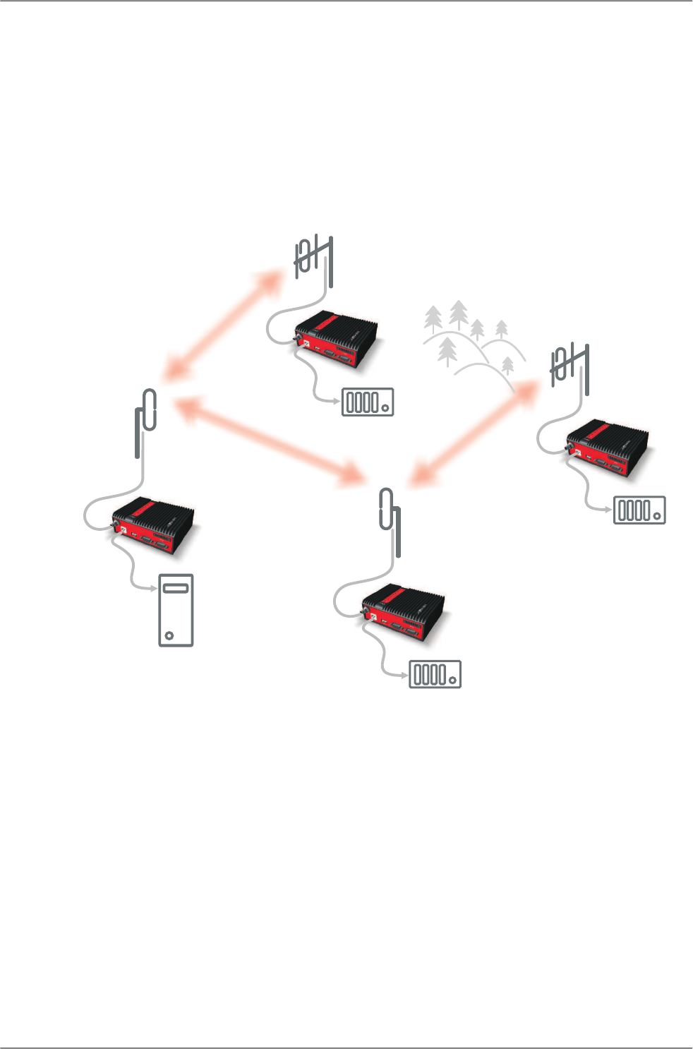
2.2. Bridge mode
A packet received through any interface is broadcast to the appropriate interfaces of all units within the
network. Packets received on COM are broadcast to both COM1 and COM2 at remote sites, allowing
you to connect 2 RTU's to any radio modem.
Any unit can be configured as a repeater. A repeater relays all packets it receives through the radio
channel. The network implements safety mechanisms which prevent cyclic loops in the radio channel
(e.g. when a repeater receives a packet from another repeater) or duplicate packets delivered to the
user interface (e.g. when RipEX receives a packet directly and then from a repeater).
Beside standard packet termination by an "Idle" period on the serial port (a pause between received
bytes) the bridge mode also offers "streaming". While in streaming mode, transmission on the radio
channel starts immediately, without waiting for the end of the received frame on COM => zero latency.
The bridge mode is suitable for all polling applications.
2.2.1. Detailed Description
Bridge mode is suitable for Point-to-Multipoint networks, where Master-Slave applications with polling-
type communication protocol are used. RipEX in bridge mode is as easy to use as a simple transparent
device, while providing communication reliability and spectrum efficiency by employing a sophisticated
protocol in the radio channel.
In bridge mode, the radio channel protocol do not solve collisions. There is a CRC check of data integrity,
however, i.e. once a message is delivered, it is 100% error free.
RipEX Radio modem & Router – © RACOM s.r.o.12
RipEX in detail
All the messages received from user interfaces (ETH&COM's) are immediately transmitted to the radio
channel.
ETH - The whole network of RipEX radiomodems behaves as a standard ethernet network bridge.
Each ETH interface automatically learns which devices (MAC addresses) are located in the local LAN
and which devices are accessible over the radio channel. Consequently, only the ethernet frames ad-
dressed to remote devices are physically transmitted on the radio channel. This arrangement saves
the precious RF spectrum from extra load which would be otherwise generated by local traffic in the
LAN (the LAN to which the respective ETH interface is connected).
COM1,COM2 - All frames received from COM1(2) are broadcast over the radio channel and transmitted
to all COM's (COM1 as well as COM2) on all radio modems within the network, the other COM on the
source RipEX excluding.
There is a special parameter TX delay (Adv. Config., Device), which should be used when all substations
(RTU's) reply to a broadcast query from the master station. In such case massive collisions would ensue
because all substations (RTU's) would reply at nearly the same time. To prevent such collision, TX
delay should be set individually in each slave RipEX. The length of responding frame, the length of
radio protocol overhead, modulation rate have to be taken into account.
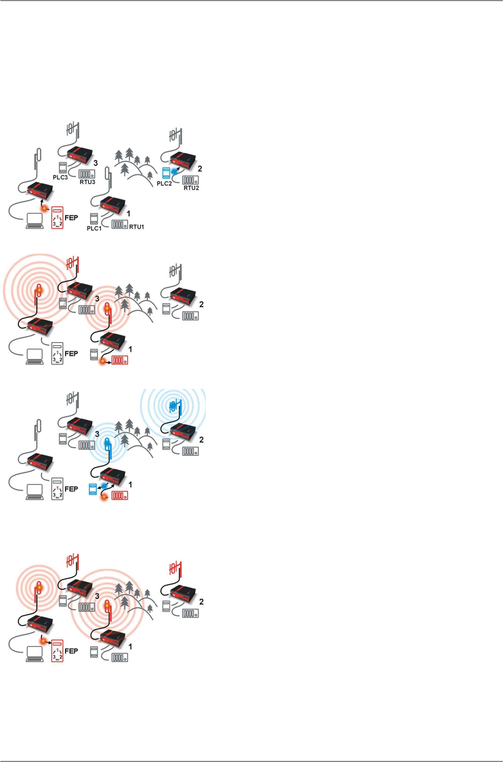
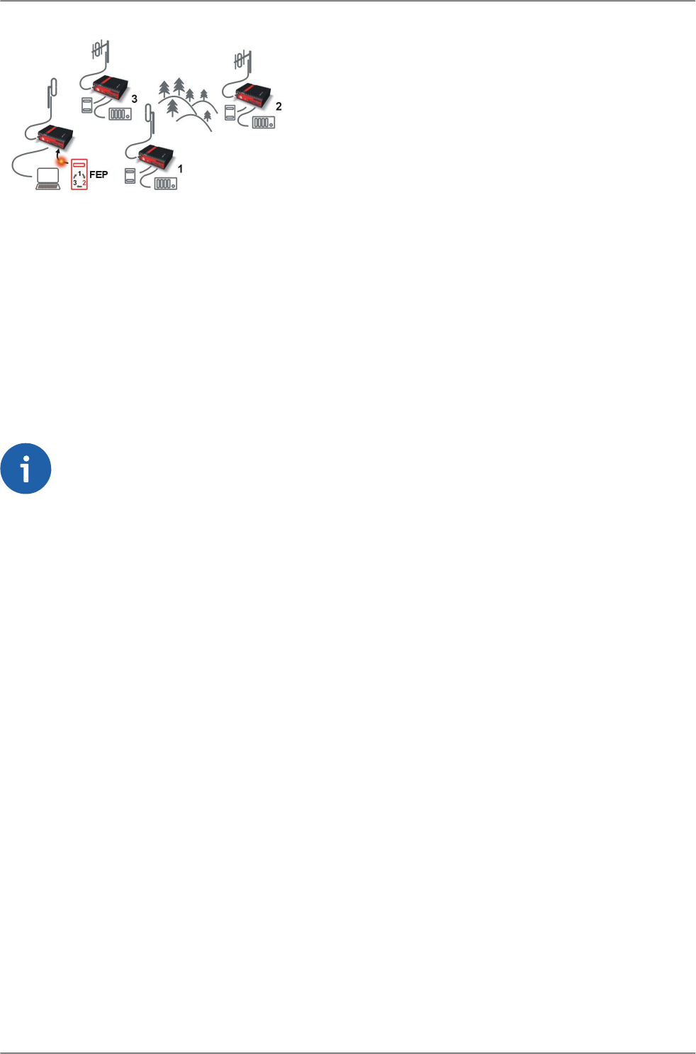
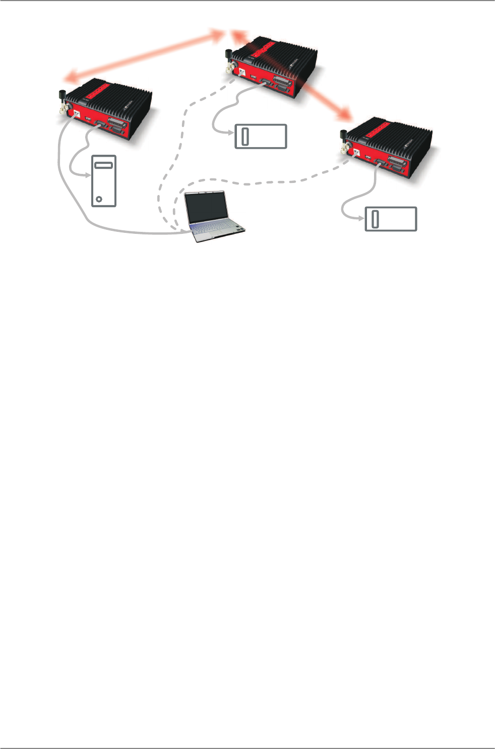
2.2.2. Functionality example
In the following, common acronyms from SCADA systems are used:
• FEP - Front End Processor, designates the communication interface equipment in the centre
• RTU - Remote Telemetry Unit, the terminal SCADA equipment at remote sites
The single digits in illustrations are “site names” and do not necessarily correspond with actual addresses
of both the RipEX's and SCADA equipment. Address configuration examples are given in the next
chapter.
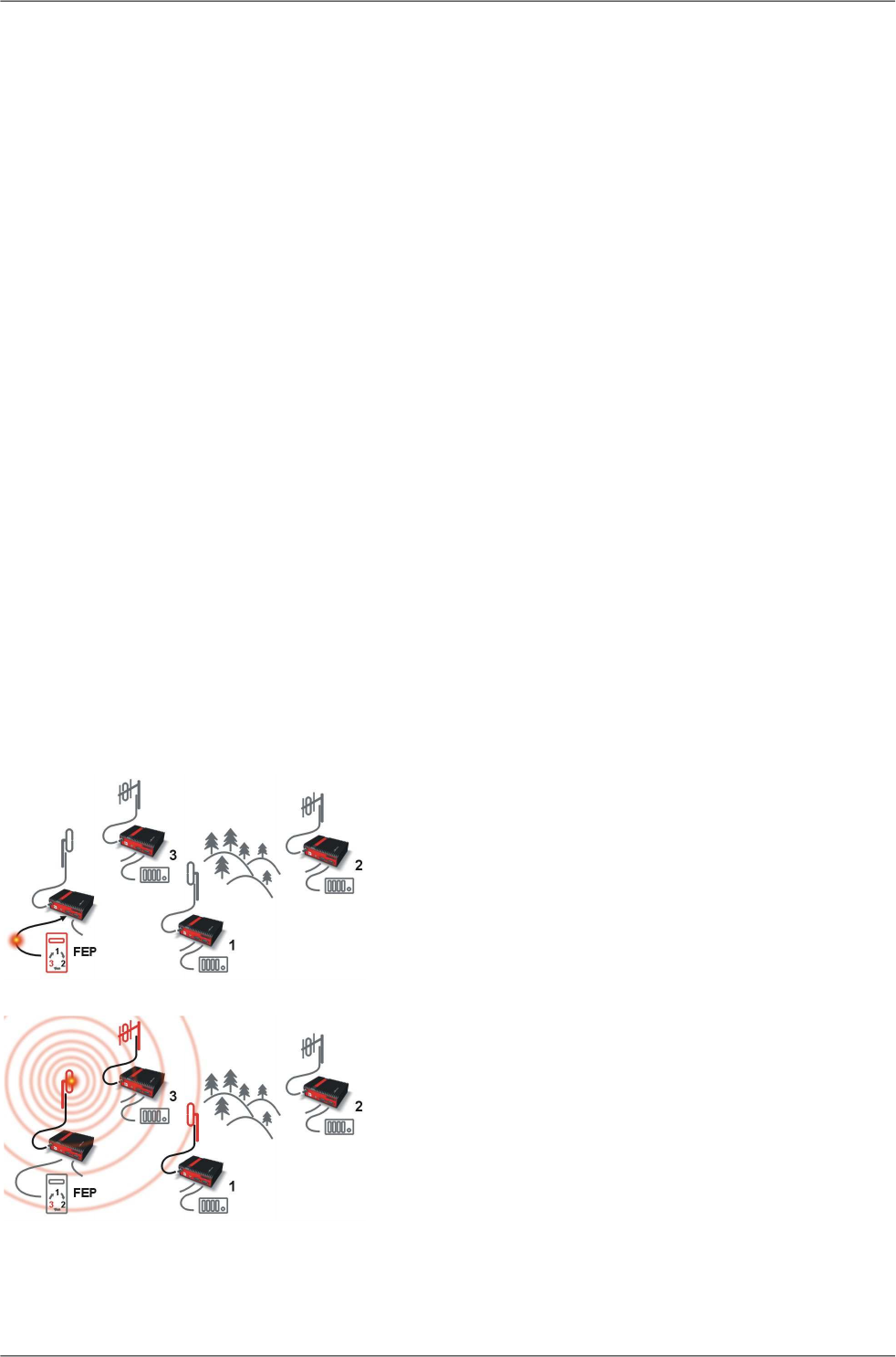
Step 1
Polling cycle starts:
FEP sends a request packet for RTU3 through COM1 to
the connected RipEX.
Step 2
FEP’s RipEX broadcasts this packet on Radio channel.
RipEX3 and RipEX1 receive this packet.
RipEX2 doesn’t receive this packet, because it is not within
radio coverage of FEP’s RipEX.
13© RACOM s.r.o. – RipEX Radio modem & Router
RipEX in detail
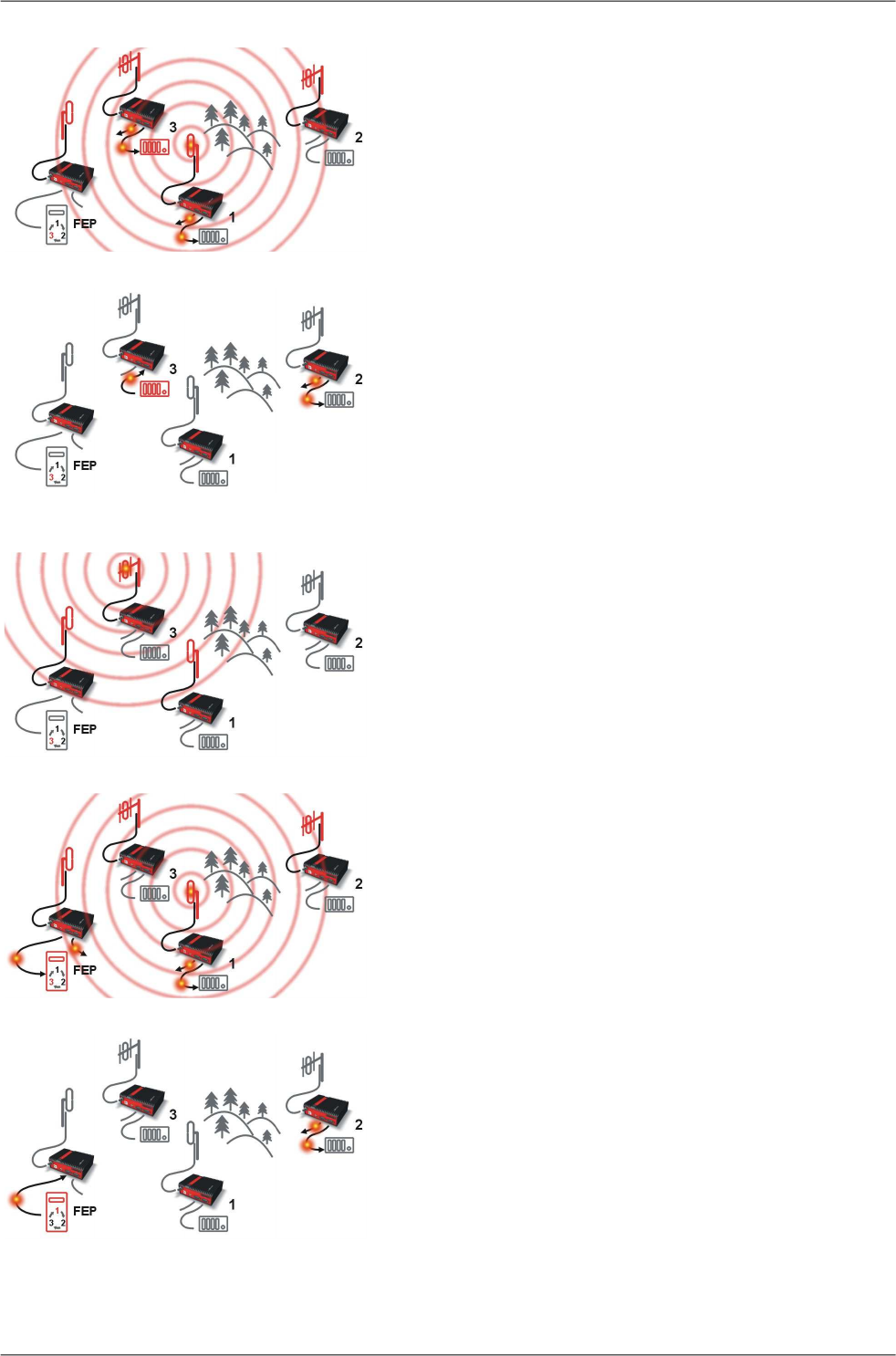
Step 3
RipEX3 and RipEX1 send the received packet to their
COM1 and COM2.
Packet is addressed to RTU3, so only RTU3 responds.
RipEX1 is set as a repeater, so it retransmits the packet
on Radio channel. Packet is received by all RipEXes.
Step 4
RipEX2 sends repeated packet to its COM1 and COM2.
RTU2 doesn’t react, because the packet is addressed to
RTU3.
RipEX3 and FEP’s RipEX do not send the repeated
packet to their COM ports, because it has already been
sent (RipEX3) or received (FEP’s RipEX) on their COM
(anti-duplication mechanism).
RTU3 sends the reply packet.
Step 5
RipEX3 broadcasts the reply packet from RTU3 on Radio
channel.
Packet is received by RipEX1 and FEP’s RipEX.
Step 6
FEP’s RipEX sends the packet (the reply from RTU3) to
FEP through COM1.
RipEX1 sends this packet to RTU1. RTU1 doesn’t react,
because the packet is addressed to FEP.
RipEX1 repeats the packet on Radio channel.
All RipEXes receive the packet.
Step 7
RipEX2 sends repeated packet to its COM1 and COM2.
RTU2 doesn’t react, because the packet is addressed to
FEP.
RipEX3 and FEP’s RipEXes do not send the repeated
packet to their COM ports, because it has been handled
already.
FEP processes the reply from RTU3 and polling cycle
continues…..
RipEX Radio modem & Router – © RACOM s.r.o.14
RipEX in detail
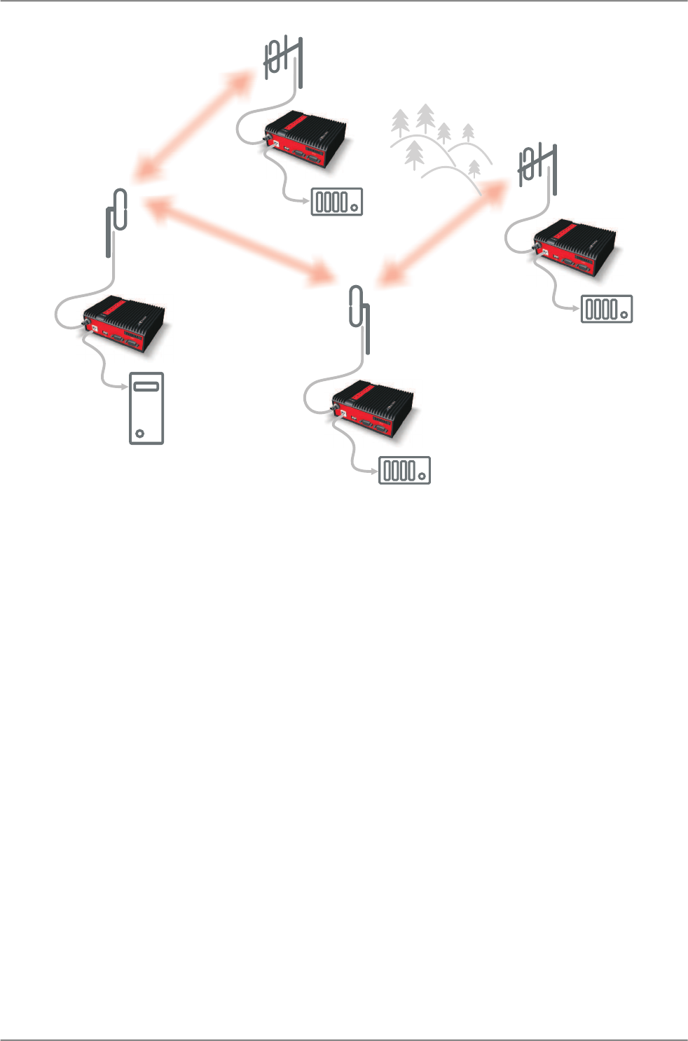
2.2.3. Configuration examples
You can see an example of IP addresses of the SCADA equipment and RipEX's ETH interfaces in the
picture below.
In Bridge mode, the IP address of the ETH interface of RipEX is not relevant for user data communic-
ation. However it is strongly recommended to assign a unique IP address to each RipEXs' ETH interface,
since it allows for easy local as well as remote service access. Moreover, leaving all RipEX's with the
same (= default) IP on the ETH interface may cause serious problems, when more RipEX's are con-
nected to the samX5e LAN, even if by accident (e.g. during maintenance).
192.168.5.51/24
192.168.5.50/24
192.168.5.12/24
192.168.5.2/24
192.168.5.3/24
192.168.5.11/24
192.168.5.1/24
192.168.5.13/24 3
FEP
50
1
2
REPEATER
Fig. 2.1: Bridge mode example
Repeater
Because using the bridge mode makes the network transparent, the use of repeaters has certain limit-
ations. To keep matters simple we recommend using a single repeater. However, if certain rules are
observed, using multiple repeaters in the same network is possible.
The total number of repeaters in the network is configured for every unit individually under Bridge mode
parameters. This information is contained in every packet sent. All units that receive such packet will
resume transmission only after sufficient time has been allowed for the packet to be repeated. The
packets received from user ports remain buffered and are sent after the appropriate time passes. This
prevents collisions between remote radio modems. There can be no repeater collisions if only one re-
peater is used.
15© RACOM s.r.o. – RipEX Radio modem & Router
RipEX in detail
Where two or more repeaters are used, collisions resulting from simultaneous reception of a repeated
packet must be eliminated. Collisions happen because repeaters repeat packets immediately after re-
ception, i.e. if two repeaters receive a packet from the centre, they both relay it at the same time. If
there is a radiomodem which is within the range of both repeaters, it receives both repeated packets
at the same time rendering them unreadable.
Examples:
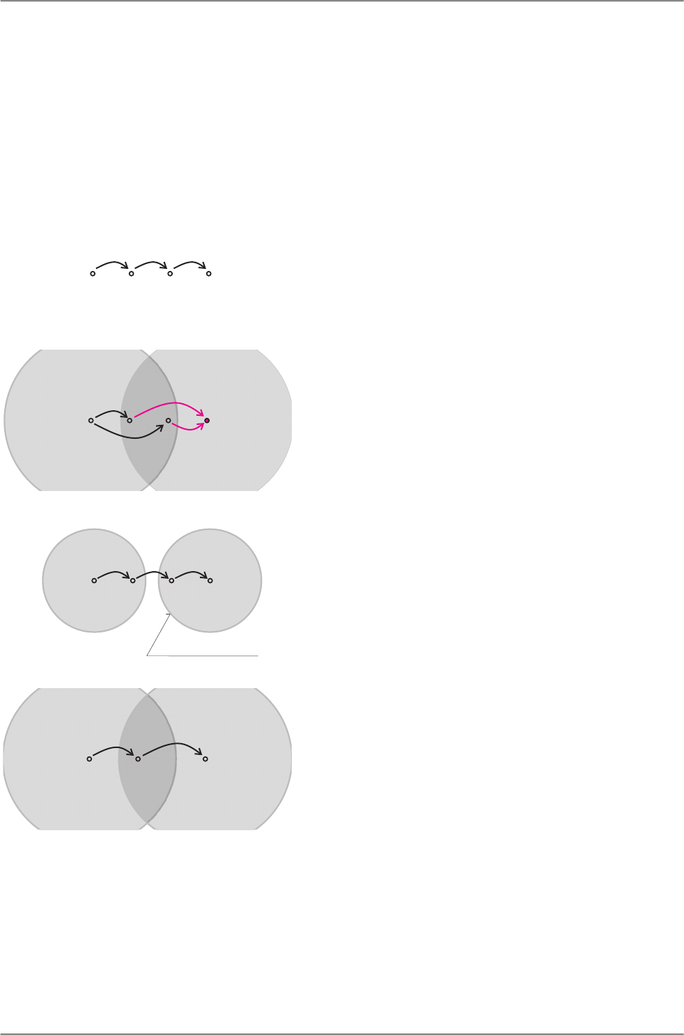
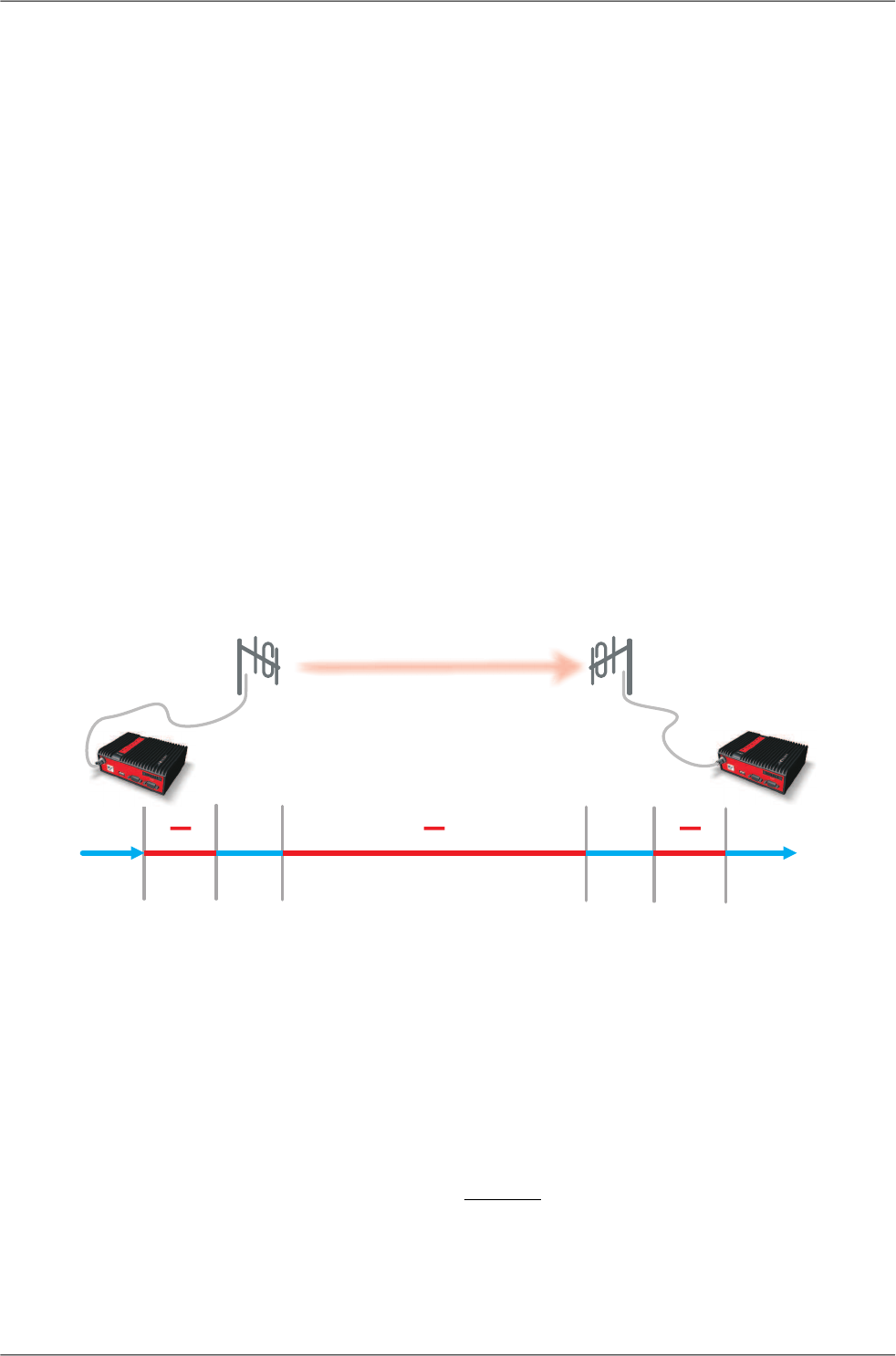
1. Repeaters connected serially
A packet is transmitted and repeated
in steps 1, 2, 3.
Centre RPT1 RPT2 Remote
1 2 3
In improperly designed networks collisions happen
if a remote radio modem lies in the range of two
X
COLLISION!
1
12
2
WRONG
CEN RPT1 RPT2 REM
repeaters (see the image): the packet sent from
the centre (1) is received by both repeaters. It is
repeated by them both (2) causing a collision at
the remote. In other words – there should not be
more than one repeater where the centre and re-
motes' coverage areas overlap.
Solution 1.
Adjust signal coverage so that RPT2 is out of range
of the centre and RPT1 is out of the range of the
GOOD
Coveragearea
123
CEN RPT1 RPT2 REM
remote radio modem. This can be achieved for
example by reducing the output power or using a
unidirectional antenna.
Solution 2.
Use a single repeater. (Whenever network layout
allows that.)
12
Good
CEN RPT1 REM
RipEX Radio modem & Router – © RACOM s.r.o.16
RipEX in detail
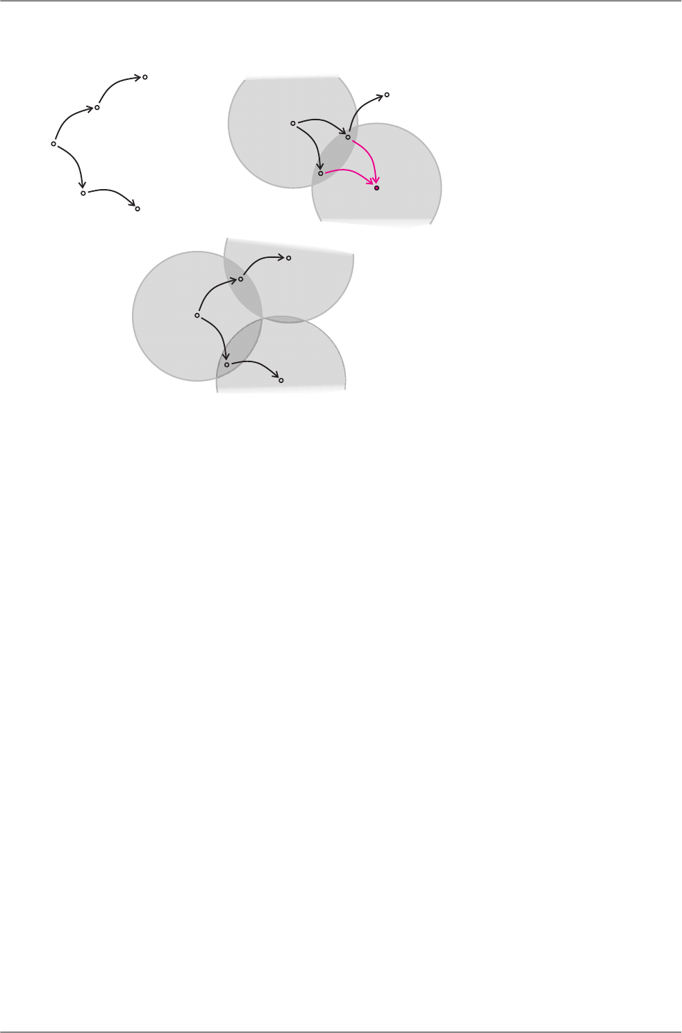
2. Parallel repeaters
Improperly designed network:
Centre
Repeater1
Remote1
1
2
1
2
Remote2
Repeater2
X
COLLISION!
GOOD
WRONG
1
2
1
2
CEN
CEN
RPT1
RPT1
REM1
REM1
1
2
1
2
REM2
REM2
RPT2
RPT2
2
- RipEX REM1 is within the range
of two repeaters (RPT1 and RPT2).
The repeaters receive a packet (1)
from the centre (CEN) and repeat
it at the same time (2) causing a
collision at REM1.
Well-designed network:
- A remote is only in the range of a
single repeater (REM1-RPT1,
REM2-RPT2).
There is always only one repeater
where the centre and remote cov-
erage areas overlap.
2.3. Router mode
RipEX works as a standard IP router with two interfaces (radio and ethernet) and two COM port devices.
There is a sophisticated anti-collision protocol on the radio channel, which checks and verifies every
single packet. Being an IP router, each unit can simultaneously work as a store-and-forward repeater
and deliver packets to the connected equipment.
The router mode is suitable for all uses. In contrast to the bridge mode, a packet reception is confirmed
over the radio channel even in very simple polling type applications, and if necessary the packet is re-
transmitted.
2.3.1. Detailed Description
Router mode is suitable for multipoint networks, where multi-master applications with any combination
of polling and/or spontaneous data protocols can be used. The proprietary link-layer protocol on the
radio channel is very sophisticated, it can transmit both unicast and broadcast frames, it has collision
avoidance capability, it uses frame acknowledgement, retransmissions and CRC checks to guarantee
data delivery and integrity even under harsh interference conditions on the radio channel.
RipEX works as a standard IP router with 2 independent interfaces: radio and ETH. Each interface has
its own MAC address, IP address and mask.
IP packets are processed according the routing table rules. You can also set the router’s default gateway
(applies to both interfaces) in the routing table.
The COM ports are treated as standard host devices, messages can be delivered to them as UDP
datagrams to selected port numbers. The destination IP address of a COM port is either the IP of ETH
or the IP of a radio interface. The source IP address of outgoing packets from COM ports is always the
IP of the ETH interface.
17© RACOM s.r.o. – RipEX Radio modem & Router
RipEX in detail
2.3.2. Functionality example
In the following example, there are two independent SCADA devices connected to RipEX's two COM
ports. One is designated RTU (Remote Telemetry Unit) and is assumed to be polled from the centre
by the FEP (Front End Processor). The other is labelled PLC (Programmable Logic Controller) and is
assumed to communicate spontaneously with arbitrary chosen peer PLCs.
Step 1
FEP sends a request packet for RTU1 through COM2 to
its connected RipEX.
Simultaneously PLC2 sends a packet for PLC1 to RipEX2
through COM1.
Step 2
FEP’s RipEX transmits an addressed packet for RTU1 on
Radio channel.
RipEX1 receives this packet, checks data integrity and
transmits the acknowledgement.
At the same time packet is sent to RTU1 through COM2.
RipEX3 receives this packet too. It doesn’t react, because
this packet is directed to RipEX1 only.
Step 3
RipEX2 waits till previous transaction on Radio channel is
finished (anti-collision mechanism).
Then RipEX2 transmits on Radio channel the addressed
packet for PLC1.
RipEX1 receives this packet, checks data integrity and
transmits acknowledgement.
At the same time packet is sent to PLC1 through COM1.
Simultaneously the reply packet from RTU1 for FEP is re-
ceived on COM2.
Step 4
RipEX1 transmitts the reply packet from RTU1 for FEP on
Radio channel.
All RipEXes receive this packet. This packet is addressed
to FEP’s RipEX, so only FEP’s RipEX reacts. It checks
data integrity and transmits the acknowledgement to
RipEX1.
At the same time the packet is sent to FEP through COM2.
RipEX Radio modem & Router – © RACOM s.r.o.18
RipEX in detail
Step 5
FEP receives the response from RTU1 and polling cycle
continues…
However any PLC or RTU can spontaneously send a
packet to any destination anytime.
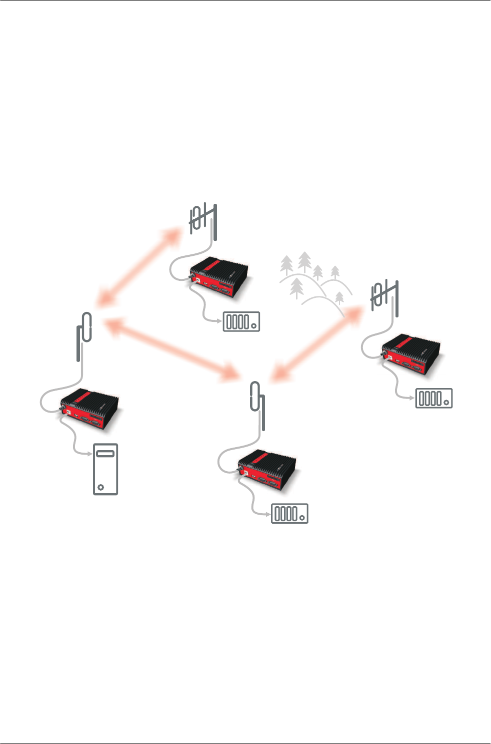
2.3.3. Configuration examples
As it was mentioned above, RipEX radiomodem works as a standard IP router with two independent
interfaces: radio and ETH. Each interface has got its own MAC address, IP address and mask.
The IP router operating principles stipulate that every unit can serve as a repeater.. Everything what
is needed is the proper configuration of routing tables.
Radio IP addresses of the RipEX’s required to communicate over the radio channel must share the
same IP network. We recommend planning your IP network so that every RipEX is connected to a
separate sub-network over the ethernet port. This helps to keep the routing tables clear and simple.
Note
Even if the IP addresses of all RipEXes in a radio channel share a single IP network, they
may not be communicating directly as in a common IP network. Only the RipEXes that are
within the radio range of each other can communicate directly. When communication with
radio IP addresses is required, routing tables must include even the routes that are within
the same network (over repeaters), which is different from common IP networks. The example
configuration below does not show such routing rules for the sake of simplicity (they are not
needed in most cases).
19© RACOM s.r.o. – RipEX Radio modem & Router
RipEX in detail
10.10.10.50/24
192.168.50.2/24
RoutingtableRipEX50:
192.168.1.0/24 10.10.10.1
192.168.2.0/24 10.10.10.1
192.168.3.0/24 10.10.10.3
DefaultGW192.168.50.2
è
è
è
192.168.2.2/24
Routingtable :
192.168.1.0/24 10.10.10.1
RipEX2
192.168.50.0/24 10.10.10.1
192.168.3.0/24 10.10.10.1
è
è
è
10.10.10.3/24
192.168.3.2/24
RoutingtableRipEX3:
192.168.50.0/24 10.10.10.50
192.168.1.0/24 10.10.10.50
192.168.2.0/24 10.10.10.50
è
è
è
10.10.10.1/24
192.168.1.1/24
192.168.1.2/24
Routingtable :
192.168.2.0/24 10.10.10.2
RipEX1
192.168.50.0/24 10.10.10.50
192.168.3.0/24 10.10.10.50
è
è
è
192.168.3.1/24 3
50
FEP
1
192.168.50.1/24
RadioIP
ETHIP
FEP IP
10.10.10.2/24
2
192.168.2.1/24
Fig. 2.2: Addressing
Formal consistency between the last byte of the radio IP address and the penultimate byte of the eth-
ernet address is not necessary but simplifies orientation. The “Addressing” image shows a routing table
next to every RipEX. The routing table defines the next gateway for each IP destination. In radio
transmission, the radio IP of the next radio-connected RipEX serves as the gateway.
Example of a route from FEP (RipEX 50) to RTU 2:
• The destination address is 192.168.2.2
• The routing table of the RipEX 50 contains this record:
Destination 192.168.2.0/24 Gateway 10.10.10.1
• Based on this record, all packets with addresses in the range from 192.168.2.1 to 192.168.2.254
are routed to 10.10.10.1
• Because RipEX 50’s radio IP is 10.10.10.50/24, the router can tell that the IP 10.10.10.1 belongs
to the radio channel and sends the packet to that address over the radio channel
• The packet is received by RipEX 1 with the address 10.10.10.1 where it enters the router
• The routing table of RipEX 1 contains the record:
Destination 192.168.2.0/24 Gateway 10.10.10.2
based on which the packet is routed to 10.10.10.2 over the radio channel
• The packet is received by RipEX 2
• The router compares the destination IP 192.168.2.2 with its own ethernet address 192.168.2.1/24
and determines that the packet’s destination is within its ETH network and sends the packet over
the ethernet interface – eventually, the packet is received by RTU 2.
RipEX Radio modem & Router – © RACOM s.r.o.20
RipEX in detail
2.3.4. Addressing hints
In large and complex networks with numerous repeaters, individual routing tables may become long
and difficult to comprehend. To keep the routing tables simple, the addressing scheme should follow
the layout of the radio network.
More specifically, every group of IP addresses of devices (both RipEX's and SCADA), which is accessed
via a repeater, should fall in a range which can be defined by a mask and no address defined by that
mask exists in different part of the network.
A typical network consisting of a single centre and number of remotes has got a tree-like layout, which
can be easily followed by the addressing scheme – see the example in the Figure Optimised addressing
below.
10.10.10.50/24
192.168.50.2/24
RoutingtableRipEX50:
192.168.0.0/22 10.10.10.1
192.168.4.0/22 10.10.10.4
DefaultGW192.168.50.2
è
è
10.10.10.2/24
192.168.2.1/24
192.168.2.2/24
Routingtable :
192.168.0.0/16 10.10.10.1
RipEX2
è
10.10.10.4/24
192.168.4.2/24
RoutingtableRipEX4:
192.168.0.0/16 10.10.10.50
è
10.10.10.1/24
192.168.1.1/24
192.168.1.2/24
Routingtable :
192.168.2.0/24 10.10.10.2
RipEX1
192.168.0.0/16 10.10.10.50
è
è
192.168.4.1/24 4
50
FEP
1
2
RadioIP
ETHIP
FEP IP
192.168.50.1/24
Fig. 2.3: Optimised addressing
The default gateway is also a very powerful routing tool, however be very careful whenever the default
route would go to the radio interface, i.e. to the radio channel. If a packet to non-existing IP destination
came to the router, it would be transmitted over the radio channel. Such packets increase the load of
the network at least, cause excessive collisions, may end-up looping etc. Consequently the default
route should always lead to the ETH interface, unless you are perfectly certain that a packet to non-
existing destination IP may never appear (remember you are dealing with complex software written
and configured by humans).
21© RACOM s.r.o. – RipEX Radio modem & Router
RipEX in detail

2.4. Serial SCADA protocols
Even when the SCADA devices are connected via serial port, communication remains secured and
address-based in all directions (centre-RTU, RTU-centre, RTU-RTU).
In router mode, RipEX utilises a unique implementation of various SCADA protocols (Modbus, IEC101,
DNP3, Comli, RP570, C24, DF1, Profibus). In this implementation SCADA protocol addresses are
mapped to RipEX addresses and individual packets are transmitted as acknowledged unicasts. Polled
remote units respond to the unit that contacted them (multi master network possible) using secure
packets. When needed, RTU-RTU parallel communication is also possible.
2.4.1. Detailed Description
Each SCADA protocol, such as Modbus, DNP3, IEC101, DF1, etc., has its own unique message format,
and more importantly, its unique way of addressing remote units. The basic task for protocol utility is
to check whether a received frame is in the correct protocol format and uncorrupted. Most of the SCADA
protocols use some type of error detection codes (Checksum, CRC, LRC, BCC, etc.) for data integrity
control, so RipEX calculates this code and check it with the received one.
RipEX radio network works in IP environment, so the basic task for the protocol interface utility is to
convert SCADA serial packets to UDP datagrams. Address translation settings are used to define the
destination IP address and UDP port. Then these UDP datagrams are sent to RipEX router, processed
and typically forwarded as unicasts over the radio channel to their destination. If the gateway defined
in the routing table belongs to the ethernet LAN, UDP datagrams are rather forwarded to the ethernet
interface. After reaching the gateway (typically a RipEX router), the datagram is again forwarded ac-
cording to the routing table.
Above that, RipEX is can to handle even broadcast packets from serial SCADA protocols. When
broadcasts are enabled in the respective Protocol settings, the defined packets are treated as broadcast
(e.g. they are not acknowledged on Radio channel). On the Repeater station, it is possible to set
whether broadcast packets shall be repeated or not.
Note: UDP datagrams can be acknowledged on the radio channel (ACK parameter of router mode)
but they are not acknowledged on the ethernet channel.
When a UDP datagram reaches its final IP destination, it should be in a RipEX router again (either its
ETH or radio interface). It is processed further according its UDP port. Either it is delivered to COM1(2)
port daemon, where the datagram is decapsulated and the data received on serial interface of the
source unit is forwarded to COM1(2), or the UDP port is that of a Terminal server or any other special
protocol daemon on Ethernet like Modbus TCP etc. Then the datagram is processed by that daemon
accordingly to the respective settings.
RipEX uses a unique, sophisticated protocol on the radio channel. It guaranties data integrity even
under heavy interference or weak signal conditions due to the 32 bit CRC used, minimises the likelihood
of a collision and retransmits frames when collision happens, etc. These features allow for the most
efficient SCADA application arrangements to be used, e.g. multi-master polling and/or spontaneous
communication from remote units and/or parallel communication between remote units, etc.
Note: The anti-collision protocol feature is available only in the router mode. The bridge mode is suitable
for simple Master-Slave arrangements with polling-type application protocol.
RipEX Radio modem & Router – © RACOM s.r.o.22
RipEX in detail

2.5. Combination of IP and serial communication
RipEX enables combination of IP and serial protocols within a single application.
Five independent terminal servers are available in RipEX. A terminal server is a virtual substitute for
devices used as serial-to-TCP(UDP) converters. It encapsulates serial protocol to TCP(UDP) and vice
versa eliminating the transfer of TCP overhead over the radio channel.
If the data structure of a packet is identical for IP and serial protocols, the terminal server can serve as
a converter between TCP(UDP)/IP and serial protocols (RS232, RS485).
RipEX also provides a built-in converter Modus RTU – Modus TCP, where data structure is not the
same, so one application may combine both protocols, Modus RTU and Modus TCP.
2.5.1. Detailed Description
Generally, a terminal server (also referred to as serial server) enables connection of devices with a
serial interface to a RipEX over the local area network (LAN). It is a virtual substitute for the devices
used as serial-to-TCP(UDP) converters.
Examples of the use:
A SCADA application in the centre should be connected to the radio network via serial interface, however,
for some reason that serial interface is not used. The operating system (e.g. Windows) can provide a
virtual serial interface to such application and converts the serial data to TCP (UDP) datagrams, which
are then received by the terminal server in RipEX. This type of connection between RipEX and applic-
ation provides best results when:
• There is no hardware serial interface on the computer
• Serial cable between RipEX and computer would be too long. E.g. the RipEX is installed very close
to the antenna to reduce feed line loss.
• LAN already exists between the computer and the point of installation
Note: The TCP (UDP) session operates only locally between RipEX and the central computer, hence
it does not increase the load on the radio channel.
In special cases, the terminal server can reduce network load from TCP applications . A TCP session
can be terminated locally at the terminal server in RipEX, user data extracted from the TCP messages
and processed as if it came from a COM port. When the data reaches the destination RipEX, it can be
transferred to the RTU either via the serial interface or via TCP (UDP), using the terminal server again.
Please note, that RipEX Terminal server implementation also supports the dynamical IP port change
in every incoming application datagram. In such case the RipEX sends the reply to the port from which
the last response has been received. This feature allows to extend the number of simultaneously
opened TCP connections between the RipEX and the locally connected application up to 10 on each
Terminal server.
2.6. Diagnostics & network management
RipEX radiomodem offers a wide range of built-in diagnostics and network management tools.
23© RACOM s.r.o. – RipEX Radio modem & Router
RipEX in detail

2.6.1. Logs
There are ‘Neighbours’ and Statistic logs in RipEX. For both logs there is a history of 20 log files
available, so the total history of saved values is 20 days (assuming the default value of 1440 min. is
used as the Log save period).
Neighbours
The ‘Neighbours’ log provides information about neighbouring units (RipEX’s which can be accessed
directly over the radio channel, i.e. without a repeater). Every RipEX on the network regularly broadcasts
its status, the set of so called “Watched values”: the probability of packet loss when transmitting data
over the radio channel, current supply voltage, internal temperature, measured RF output power, the
Voltage Standing Wave Ratio on the antenna feed line and the total number of packets received from
/ transmitted to ETH, COM1, COM2 interfaces. In addition, the RipEX that records this data in its log
also keeps track of how many times it listened to its neighbouring unit as well as of the RSS and DQ
recorded. See Adv. Conf., Diagnostic for more.
Statistic
The ‘Statistic’ log provides information about the volume of data traffic on all interfaces: radio, ETH,
COM1, COM2. It offers detailed information about the number of transmitted packets, their size and
the throughput per second. Moreover, a detailed division into user and service packets is available for
the radio channel. See chapter Adv. Conf., Diagnostic for more.
2.6.2. Graphs
An independent database periodically stores the Watched values (see 'Neighbours' log above) from
up to five neighbouring RipEX's and from the local one, there including most important values from the
Statistic log. All these values can be displayed as graphs.
The graphs are available in summary and detailed versions. Detailed logging is triggered on when a
threshold value has been reached for the specific item to enable a more detailed investigation into the
units’ operation when an alarm event occurs. Each graph can display two different elements at once,
including their set thresholds. Each of the values may originate from a different RipEX unit.
See chapter Adv. Conf., Graphs for more.
2.6.3. SNMP
RipEX implements an SNMP client ver. 1. The values provided by RipEX are shown in the MIB table.
RipEX also allows generating SNMP traps when thresholds have been reached for the monitored values:
RSScom, DQcom, TXLost[%], Ucc, Temp, PWR, VSWR, ETH[Rx/Tx], COM1[Rx/Tx], COM2[Rx/Tx],
HW Alarm Input.
See chapter RipEX App notes, SNMP for RACOM RipEX1for more.
2.6.4. Ping
To diagnose the individual radio links RipEX is equipped with an enhanced Ping tool. In addition to the
standard info such as the number of sent and received packets or the round trip time, it provides the
1http://www.racom.eu/eng/products/m/ripex/app/snmp.html
RipEX Radio modem & Router – © RACOM s.r.o.24
RipEX in detail
overall load, the resulting throughput, BER, PER and specific data about the quality of the radio trans-
mission, RSS and DQ for the weakest radio link on the route.
See chapter Adv. Conf., Ping for details.
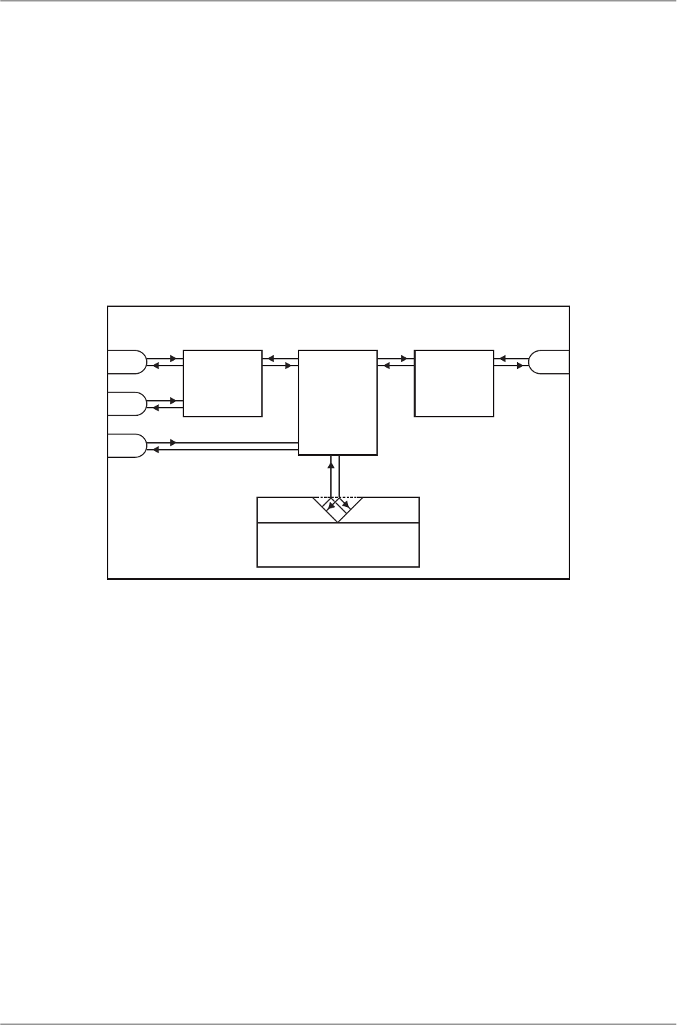
2.6.5. Monitoring
TMonitoring is an advanced on-line diagnostic tool, which enables a detailed analysis of communication
over any of the interfaces of a RipEX router. In addition to all the physical interfaces (RADIO, ETH,
COM1, COM2), some internal interfaces between software modules (e.g. Terminal servers, Modus
TCP server etc.) can be monitored when such advanced diagnostics is needed.
Monitoring output can be viewed on-line or saved to a file in the RipEX (e.g. a remote RipEX) and
downloaded later.
COMPORTS
MODULE ROUTER
&
BRIDGE
MODULE
TERMINAL &MODBUSTCP
SERVERS
RADIO
CHANNEL
MODULE
COM1
COM2
ETH
RADIO
virtualcom eth
RipEX
Rx
Tx
Rx
Tx
Rx
Tx
Rx
Tx
Rx
Tx
Rx
Tx
Rx
Tx
Fig. 2.4: Monitoring
See chapter Adv. Conf., Monitoring for details.
2.7. Firmware update and upgrade
Occasionally RipEX firmware update or upgrade is released. An update improves functionality and/or
fix software bugs. Updates can be downloaded for free from www.racom.eu.
A firmware upgrade implements significant improvements and new functions which take the product
to a new level. Downloading and applying a firmware upgrade is the same as with firmware update.
However a software key may have to be purchased and applied to activate the new functionality or the
upgrade itself (see the next chapter).
See chapter Adv. Conf., Firmware for more.
2.8. Software feature keys
Certain advanced RipEX features are activated with software keys. Among such code protected features
are the Router mode, 83 kbps (High speed), COM2, 10 W. This enables the users to initially purchase
only the functionality they require and buy additional functions as the requirements and expectations
25© RACOM s.r.o. – RipEX Radio modem & Router
RipEX in detail

grow. This protects the investment into the hardware. Thanks to SDR-based hardware design of RipEX
no physical replacement is necessary – the user simply buys a key and activates the feature.
Software keys are always tied to a specific RipEX production code. When purchasing a software key,
this production code must be given.
See chapter Adv. Conf., SW feature keys for more.
RipEX Radio modem & Router – © RACOM s.r.o.26
RipEX in detail

3. Network planning
The significance of planning for even a small radio network is often neglected. A typical scenario in
such cases goes as follows – there's not enough time (sometimes money) to do proper planning, so
the network construction is started right away while decisions on antennas etc. are based mainly on
budget restrictions. When the deadline comes, the network is ready but its performance does not meet
the expectations. Finally the (expensive) experts are invited to fix the problem and that fix costs ten
times more than a proper design process done beforehand would have.
The following paragraphs are not a guide to network planning – that is a topic far beyond the scope of
a product manual. What is provided is the essential RipEX data needed plus some comments on
common problems which should be addressed during the planning process.
3.1. Data throughput, response time
A UHF radio network provides very limited bandwidth for principal reasons. Hence the first and very
important step to be taken is estimating/calculating the capacity of the planned network. The goal is to
meet the application bandwidth and time-related requirements. Often this step determines the layout
of the network, for example when high speed is necessary, only near-LOS (Line-of-sight) radio hops
can be used.
RipEX offers an unprecedented range of data rates. The channel width available and signal levels ex-
pected/measured on individual hops limit the maximum rate which can be used. The data rate defines
the total capacity of one radio channel in one area of coverage, which is shared by all the radio modems
within the area. Then several overhead factors, which reduce the total capacity to 25-90% of the "raw"
value, have to be considered. They are e.g. RF protocol headers, FEC, channel access procedures
and number of store-and-forward repeaters. There is one positive factor left – an optimum compression
(e.g. IP optimization) can increase the capacity by 20-200%.
All these factors are heavily influenced by the way the application loads the network. For example, a
simple polling-type application results in very long alarm delivery times – an event at a remote is reported
only when the respective unit is polled. However the total channel capacity available can be 60-95%
of the raw value, since there are no collisions. A report-by-exception type of load yields much better
application performance, yet the total channel capacity is reduced to 25-35% because of the protocol
overhead needed to avoid and solve collisions.
The basic calculations of network throughput and response times for different RipEX settings can be
done at www.racom.eu1.
Let us add one comment based on experience. Before committing to the actual network design, it is
very wise to do a thorough bench-test with real application equipment and carefully monitor the load
generated. A difference against the datasheets, which may be negligible in a LAN environment, may
have fundamental consequences for the radio network design. To face that "small" difference when
the network is about to be commissioned may be a very expensive experience. The bench test layout
should include the application centre, two remotes (at least) and the use of a repeater. See the following
picture for an example.
1http://www.racom.eu/eng/products/radio-modem-ripex.html#calculation
27© RACOM s.r.o. – RipEX Radio modem & Router
Network planning
Centre
RTU
config.PC
RTU
dummy
antenna
Fig. 3.1: Application bench test
3.2. Frequency
Often the frequency is simply given. If there is a choice, using the optimum frequency range can make
a significant difference. Let us make a brief comparison of the most used UHF frequency bands.
160 MHz
The best choice when you have to cover a hilly region and repeaters are not an option. The only fre-
quency of the set of options which can possibly make it to a distant valley, 20 km from your nearest
point-of-presence, it can reach a ship 100 km from the shore base. The penalty you pay is tremendous
– high level of noise in urban and industry areas, omnipresent multi-path propagation, vulnerability to
numerous special propagation effects in troposphere etc. Consequently this frequency band is suitable
for low speeds using robust modulation techniques only, and even then a somewhat lower long-term
communication reliability has to be acceptable for the application.
450 MHz
The most popular of UHF frequency bands. It still can get you slightly “beyond the horizon”, while the
signal stability is good enough for 99% (or better) level of reliability. Multi-path propagation can be a
problem, hence high speeds may be limited to near-LOS conditions. Urban and industrial noise does
not pose a serious threat (normally), but rather the interference caused by other transmissions is quite
frequent source of disturbances.
900 MHz
This band requires planning the network in “microwave” style. Hops longer than about 1 km have to
have “almost” clear LOS (Line-of-sight). Of course a 2–5 km link can handle one high building or a
bunch of trees in the middle, (which would be a fatal problem for e.g. an 11 GHz microwave). 900 MHz
also penetrates buildings quite well, in an industrial environment full of steel and concrete it may be
the best choice. The signal gets “everywhere” thanks to many reflections, unfortunately there is bad
news attached to this - the reliability of high speed links in such environment is once again limited.
Otherwise, if network capacity is your main problem, then 900 MHz allows you to build the fastest and
RipEX Radio modem & Router – © RACOM s.r.o.28
Network planning
most reliable links. The price you pay (compared to lower frequency bands) is really the price – more
repeaters and higher towers increase the initial cost. Long term reliable performance is the reward.
The three frequency bands discussed illustrate the simple basic rules – the higher the frequency, the
closer to LOS the signal has to travel. That limits the distance over the Earth's surface – there is no
other fundamental reason why shorter wavelengths could not be used for long distance communication.
On the other hand, the higher the frequency, the more reliable the radio link is. The conclusion is then
very simple – use the highest frequency band you can.
3.3. Signal budget
For every radio hop which may be used in the network, the signal level at the respective receiver input
has to be calculated and assessed against requirements. The fundamental requirements are two – the
data rate, which is dictated by total throughput and response times required by the application, and the
availability, which is again derived from the required reliability of the application. The data rate translates
to receiver sensitivity and the availability (e.g. 99,9 % percent of time) results in size of the fade margin.
The basic rule of signal budget says, that the difference between the signal level at the receiver input
and the guaranteed receiver sensitivity for the given data rate has to be greater than the fade margin
required:
RX signal [dBm] – RX sensitivity [dBm] >= Fade margin [dB]
To calculate the RX signal level, we follow the RF signal path:
TX
output
RX
input
feedline
loss
feedline
loss
pathloss
TX
antenna
gain
RX
antenna
gain
+ +
Fig. 3.2: Signal path
example:RX signal [dBm] =
dBm (TX output 1 W)+30.0+ TX output [dBm]
dB (20m cable RG-213 U, 400 MHz)-2.5- TX antenna feeder loss [dB]
dBi (half-wave dipole, 0 dBd)+2.1+TX antenna gain [dBi]
dB calculated from field measurement)-125.0- Path loss [dB]
dB (7-al Yagi antenna, 7.6 dBd)+9.7+ RX antenna gain [dBi]
dB (10 m cable RG-58 CU, 400 MHz)-3.1- RX antenna feeder loss [dB]
dBm Received Signal Strength (RSS)= -88.8
The available TX output power and guaranteed RX sensitivity level for the given data rate have to be
declared by the radio manufacturer. RipEX values can be found in Table 4.6, “Technical parameters”.
29© RACOM s.r.o. – RipEX Radio modem & Router
Network planning

Antenna gains and directivity diagrams have to be supplied by the antenna manufacturer. Note that
antenna gains against isotropic radiator (dBi) are used in the calculation. The figures of feeder cable
loss per meter should be also known. Note that coaxial cable parameters may change considerably
with time, especially when exposed to an outdoor environment. It is recommended to add a 50-100 %
margin for ageing to the calculated feeder loss.
3.3.1. Path loss and fade margin
The path loss is the key element in the signal budget. Not only does it form the bulk of the total loss,
the time variations of path loss are the reason why a fade margin has to be added. In reality, very often
the fade margin is the single technical figure which expresses the trade-off between cost and perform-
ance of the network. The decision to incorporate a particular long radio hop in a network, despite that
its fade margin indicates 90 % availability at best, is sometimes dictated by the lack of investment in a
higher tower or another repeater. Note that RipEXs Auto-speed feature allows the use of a lower data
rate over specific hops in the network, without the need to reduce the rate and consequently the
throughput in the whole network. Lower data rate means lower (= better) value of receiver sensitivity,
hence the fade margin of the respective hop improves. See the respective Application note to learn
more on the Auto-speed feature.
When the signal path profile allows for LOS between the TX and RX antennas, the standard formula
for free-space signal loss (below) gives reliable results:
Path loss [dB] = 20 * log10 (distance [km]) + 20 * log10 (frequency [MHz]) + 32.5
In the real world the path loss is always greater. UHF radio waves can penetrate obstacles (buildings,
vegetation), can be reflected from flat objects, can bend over round objects, can disperse behind sharp
edges – there are numerous ways how a radio signal can propagate in non-LOS conditions. The addi-
tional loss when these propagation modes are involved (mostly combined) is very difficult to calculate.
There are sophisticated methods used in RF design software tools which can calculate the path loss
and its variations (statistical properties) over a computer model of terrain. Their accuracy is unfortunately
very limited. The more obstacles on the path, the less reliable is the result. Such a tool can be very
useful in the initial phase of network planning, e.g. to do the first network layout for the estimate of total
throughput, however field measurements of every non-LOS radio hop should be done before the final
network layout is designed.
Determining the fade margin value is even more difficult. Nevertheless the software tools mentioned
can give some guidance, since they can calculate the statistical properties of the signal. Generally the
fade margin (for given availability) is proportional to the difference between the real path loss and the
LOS path loss over the same distance. Then it is about inversely proportional to frequency (in the UHF
range at least). To give an example for 10 km, non-LOS, hop on 450 MHz, fade margin of 20 dB is a
bare minimum. A field test may help again, provided it is run for longer period of time (hours-days).
RipEX diagnostic tools (ping) report the mean deviation of the RSS, which is a good indication of the
signal stability. A multiple of the mean deviation should be added to the fade margin.
3.4. Multipath propagation, DQ
Multipath propagation is the arch-enemy of UHF data networks. The signal coming out of the receiving
antenna is always a combination of multiple signals. The transmitted signal arrives via different paths,
by the various non-LOS ways of propagation. Different paths have different lengths, hence the waveforms
are in different phases when hitting the receiving antenna. They may add-up, they may cancel each
other out.
RipEX Radio modem & Router – © RACOM s.r.o.30
Network planning
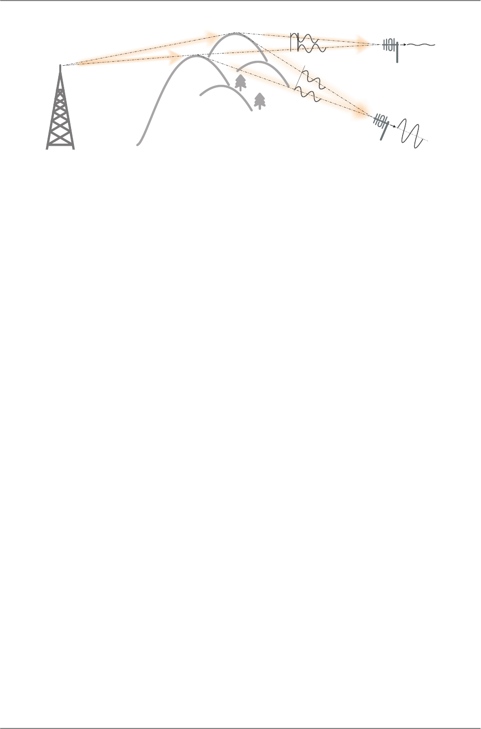
TXantenna
Fig. 3.3: Multipath propagation
What makes things worse is that the path length changes over time. Since half the wavelength – e.g.
0.3 m at 450 MHz - makes all the difference between summation and cancellation, a 0.001% change
of a path length (10 cm per 10 km) is often significant. And a small change of air temperature gradient
can do that. Well, that is why we have to have a proper fade margin. Now, what makes things really
bad is that the path length depends also on frequency. Normally this dependency is negligible within
the narrow channel. Unfortunately, because of the phase combinations of multiple waveforms, the
resulting signal may get so distorted, that even the sophisticated demodulating techniques cannot read
the original data. That is the situation known to RF data network engineers – signal is strong enough
and yet “it” does not work.
That is why RipEX reports the, somewhat mystic, figure of DQ (Data Quality) alongside the RSS. The
software demodulator uses its own metrics to assess the level of distortion of the incoming signal and
produces a single number in one-byte range (0–255), which is proportionate to the “quality” of the signal.
Though it is very useful information, it has some limitations. First, it is almost impossible to determine
signal quality from a single packet, especially a very short one. That results in quite a jitter of DQ values
when watching individual packets. However when DQ keeps jumping up and down it indicates a serious
multipath problem. In fact, when DQ stays low all the time, it must be noise or permanent interference
behind the problem. The second issue arises from the wide variety of modulation and data rates RipEX
supports. Though every attempt has been made to keep the DQ values modulation independent, the
differences are inevitable. In other words, experience is necessary to make any conclusions from DQ
reading. The less experience you have, the more data you have to collect on the examined link and
use other links for comparison.
The DQ value is about proportional to BER (bit error ratio) and about independent of the data rate and
modulation used. Hence some rule-of-thumb values can be given. Values below 100 mean the link is
unusable. At 125 short packets should get through with some retransmissions, 150 and above can be
considered “good” values.
3.4.1. How to battle with multipath propagation?
The first step is the diagnosis. We have to realize we are in trouble and only a field measurement can
tell us that. We should forget about software tools and simply assume that a multipath problem may
appear on every non-LOS hop in the network.
These are clear indicators of a serious multipath propagation problem:
• directional antennas "do not work", e.g. a dipole placed at the right spot yields a better RSS than
a long Yagi, or rotating the directional antenna shows several peaks and troughs of the signal and
no clear maximum
• RSS changes rapidly (say 10 dB) when antenna is moved by less than a meter in any direction
31© RACOM s.r.o. – RipEX Radio modem & Router
Network planning
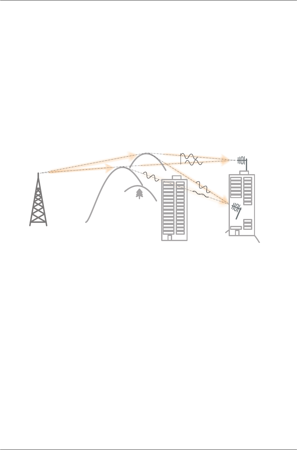
• ping test displays the mean deviation of RSS greater than 6 dB
• DQ value keeps "jumping" abnormally from frame to frame
Quite often all the symptoms mentioned can be observed at a site simultaneously. The typical "beginner"
mistake would be to chase the spot with the best RSS with an omnidirectional antenna and installing
it there. Such a spot may work for several minutes (good luck), sometimes for several weeks (bad luck,
since the network may be in full use by then). In fact, installing in such a spot guaranties that trouble
will come - the peak is created by two or more signals added up, which means they will cancel out
sooner or later.
The right strategy is to find an arrangement where a single signal becomes dominant, possibly the
most stable one. "Sweeping" a directional antenna around the place (in different heights and with dif-
ferent polarization) can tell us where the signals come from. If individual signals come from different
directions, there is a good chance a long yagi can solve the problem by selecting just one of the bunch.
Finding a spot where the unwanted signal is blocked by a local obstacle may help as well (e.g. installing
at a side of the building instead of at the roof).
TXantenna
better
multipath
Fig. 3.4: Antenna location
When the multiple signals come from about the same direction, a long yagi alone would not help much.
We have to move away from the location, again looking for a place where just one of the signals becomes
dominant. 20–50 metres may save the situation, changing the height (if possible) is often the right
solution. Sometimes changing the height means going down, not up, e.g. to the base of the building
or tower.
We have to remember our hop has two ends, i.e. the solution may be to change antenna or its placement
at the opposite end. If everything fails, it is better to use another site as a repeater. Even if such prob-
lematic site seems to be usable after all (e.g. it can pass commissioning tests), it will keep generating
problems for ever, hence it is very prudent to do something about it as early as possible.
Note: Never design hops where a directional antenna is used for a direction outside its main lobe.
However economical and straightforward it may seem, it is a dangerous trap. Enigmatic cases of drop-
outs lasting couple of minutes every other day, over a clear LOS hops were created exactly like that.
They look like interference which is very difficult to identify and , alas, they are caused by pure multipath
propagation, a self-made one. So always use a combiner and another directional antenna if such ar-
rangement is needed. Always.
RipEX Radio modem & Router – © RACOM s.r.o.32
Network planning
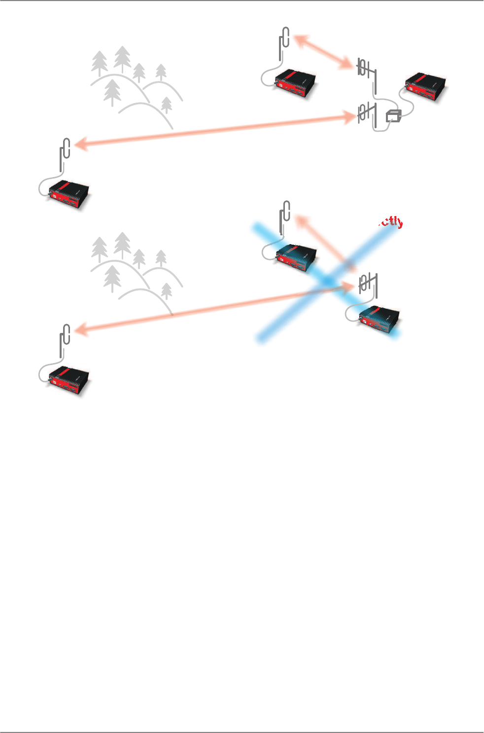
combiner
correctly
incorrectly
Fig. 3.5: Main lobe
3.5. Network layout
Certainly the network layout is mostly (sometimes completely) defined by the application. When the
terrain allows for direct radio communication among all sites in the network, the designer can do neither
too good nor too bad a job. Fortunately for RF network designers, the real world is seldom that simple.
The conditions every single radio hop has to meet were discussed in previous paragraphs. If we are
so lucky, that different layouts meeting that conditions are possible, we should exploit that for the be-
nefit of the network. The following rules should be followed when defining the layout of radio hops:
• dominant radio sites (e.g. telco towers on hill tops) should be avoided whenever possible. Placing
a single repeater which serves most part of the network from the top of a hill is a straightforward
but worst alternative, which makes the whole network very vulnerable. First, a dominant site is ex-
posed to interference from a large area; second, such site is typically crowded with radio equipment
of all kinds, which keeps being added, moved (also failing to work properly), so local interference
may appear anytime; third, it makes the majority of communication paths dependent on a single
site, so one isolated failure may stop almost the entire network.
• when total throughput is important, typically in report-by-exception networks, splitting the network
into several independent or only slightly overlapping areas of coverage can help. The placement
33© RACOM s.r.o. – RipEX Radio modem & Router
Network planning
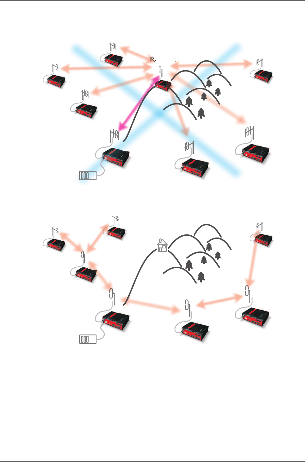
of repeaters which serve the respective areas is crucial. They should be isolated from each other
whenever possible.
M
Repeater
Centre
incorrectly
Fig. 3.6: Dominant repeater
MCentre
Fig. 3.7: Isolated branches
• in report-by-exception networks the load of hops connecting the centre to major repeaters forms
the bottle-neck of total network capacity. Moving these hops to another channel, or, even better, to
a wire (fibre, microwave) links can multiply the throughput of the network. It saves not only the load
itself, it also significantly reduces the probability of collision. More on that in the following chapter
3.6..
RipEX Radio modem & Router – © RACOM s.r.o.34
Network planning
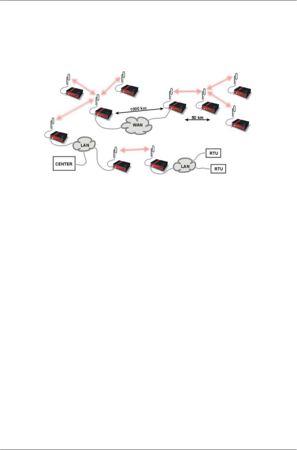
3.6. Hybrid networks
If an extensive area needs to be covered and multiple retranslation would be uneconomical or unsuitable,
RipEX’s can be interconnected via any IP network (WLAN, Internet, 3G, etc.). This is quite simple be-
cause RipEX is a standard IP router with an ethernet interface. Consequently interconnecting two or
more RipEX's over a nested IP network is a standard routing issue and the concrete solution depends
on that network.
3.7. Assorted practical comments
Let us mention few issues, whose influence on network reliability or performance is sometimes neglected
by less experienced planners:
• Both vegetation and construction can grow. Especially when planning a high data rate hop which
requires a near-LOS terrain profile, take into consideration the possible future growth of obstacles.
• When the signal passes a considerable amount of vegetation (e.g. a 100m strip of forest), think of
the season. Typically the path loss imposed by vegetation increases when the foliage gets dense
or wet (late spring, rainy season). Hence the fade margin should be increased if your field measure-
ments are done in a dry autumn month. The attenuation depends on the distance the signal must
penetrate through the forest, and it increases with frequency. According to a CCIR, the attenuation
is of the order of 0.05 dB/m at 200 MHz, 0.1 dB/m at 500 MHz, 0.2 dB/m at 1 GHz. At lower frequen-
cies, the attenuation is somewhat lower for horizontal polarization than for vertical, but the difference
disappears above about 1 GHz.
• Though being a rare problem, moving metallic objects may cause serious disruptions, especially
when they are close to one end of the radio hop. They may be cars on a highway, blades of a wind
turbine, planes taking off from a nearby airport runway etc.
• Even when the signal is very strong, be careful when considering various cheap whips or more
generally any antennas requiring a ground plane to function properly. A tempting scenario is to use
the body of the metallic box, where the radio modem and connected application equipment (often
a computer) is installed, as the ground plane, which leads to never-ending problems with locally
generated noise. The ground plane forms an integral part of such an antenna, hence it has to be
in a safe distance (several metres) from any electronic equipment as well as the antenna itself. A
metallic plate used as shielding against interference must not form a part of the antenna.
35© RACOM s.r.o. – RipEX Radio modem & Router
Network planning
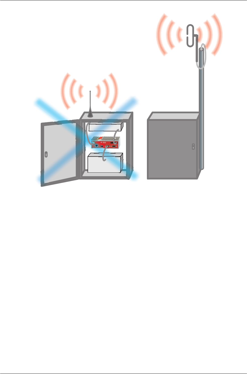
incorectly correctly
Powersupply
RTU
Fig. 3.8: Antenna mounting
• Do not underestimate ageing of coaxial cables, especially at higher frequencies. Designing a 900
MHz site with 30 m long antenna cable run outdoors would certainly result in trouble two years later.
• We recommend to use vertical polarization for all radio modem networks.
RipEX Radio modem & Router – © RACOM s.r.o.36
Network planning
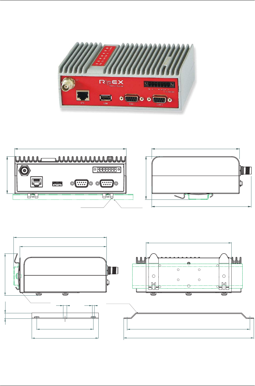
4. Product
RipEX is built into a rugged die-cast aluminium casing that allows for multiple installation possibilities,
see Section 6.1, “Mounting”.
4.1. Dimensions
DIN35Rail
DINRailClip
134
150 118
58
50
Fig. 4.1: RipEX dimensions, see more
133
95
124
60
122
122
175
L -bracket Flat-bracket
8
70
2×o4,5 4×M3
/
Fig. 4.2: L-bracket and Flat-bracket, see more
37© RACOM s.r.o. – RipEX Radio modem & Router
Product
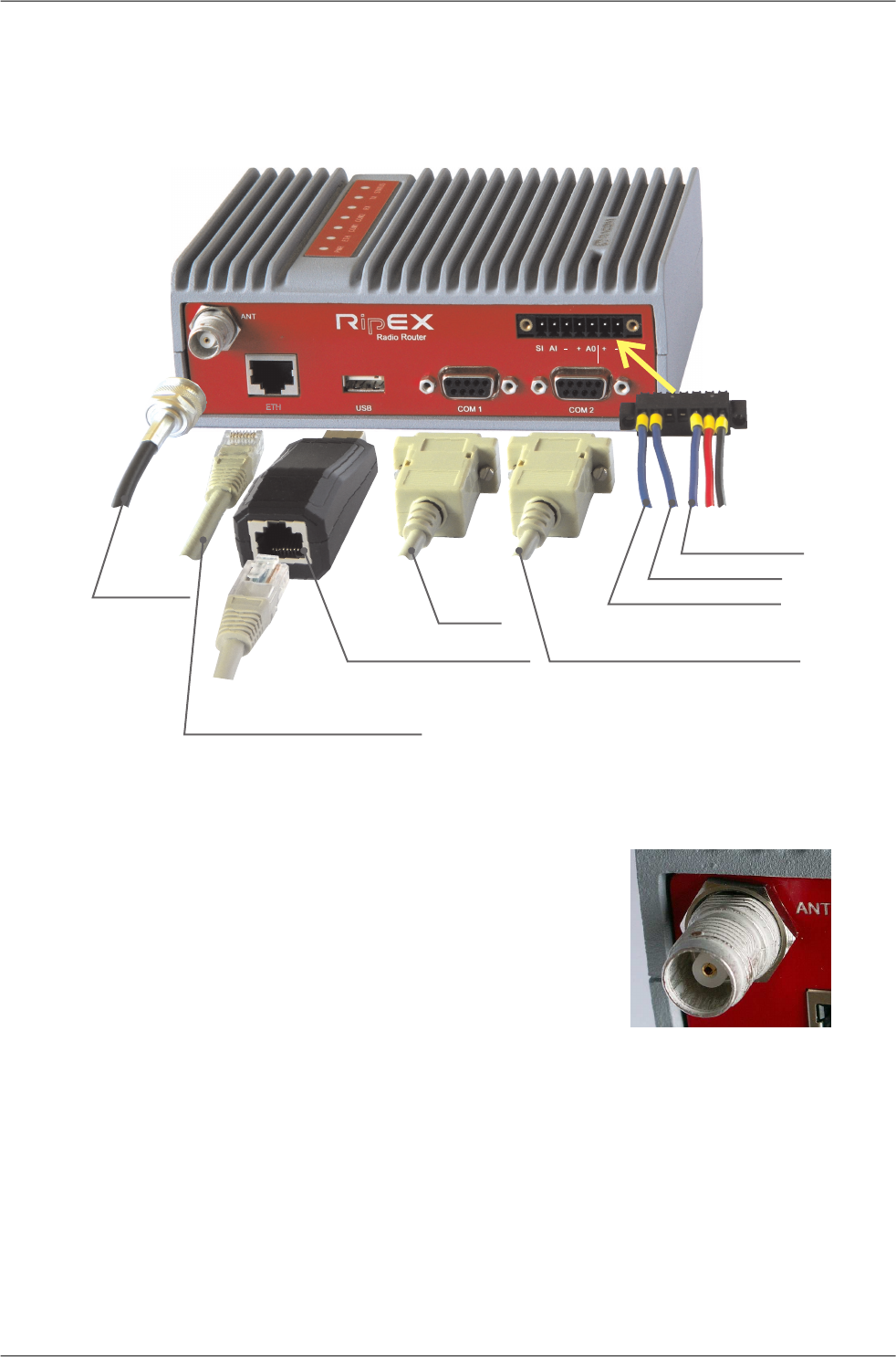
4.2. Connectors
All connectors are located on the front panel. The upper side features an LED panel. The RESET button
is located in an opening in the bottom side.
ALARMOUT.
ALARMINPUT
+ –
SLEEP -WAKEUP
COM1
COM2dataequipment,RTU
ETHdataequipment,RTU
LAN,controlPC
ETH/USB ADAPTER
ANTENNA
10–30VDC
+
+
ETH
Fig. 4.3: Connectors
4.2.1. Antenna
Fig. 4.4: Antenna connector TNC
An antenna can connect to RipEX via TNC female 50Ω connector.
A model with two antenna connectors can be supplied to order,
in which the Rx and Tx antennas are separate. See chapter
Section 4.5, “Model offerings”.
RipEX Radio modem & Router – © RACOM s.r.o.38
Product
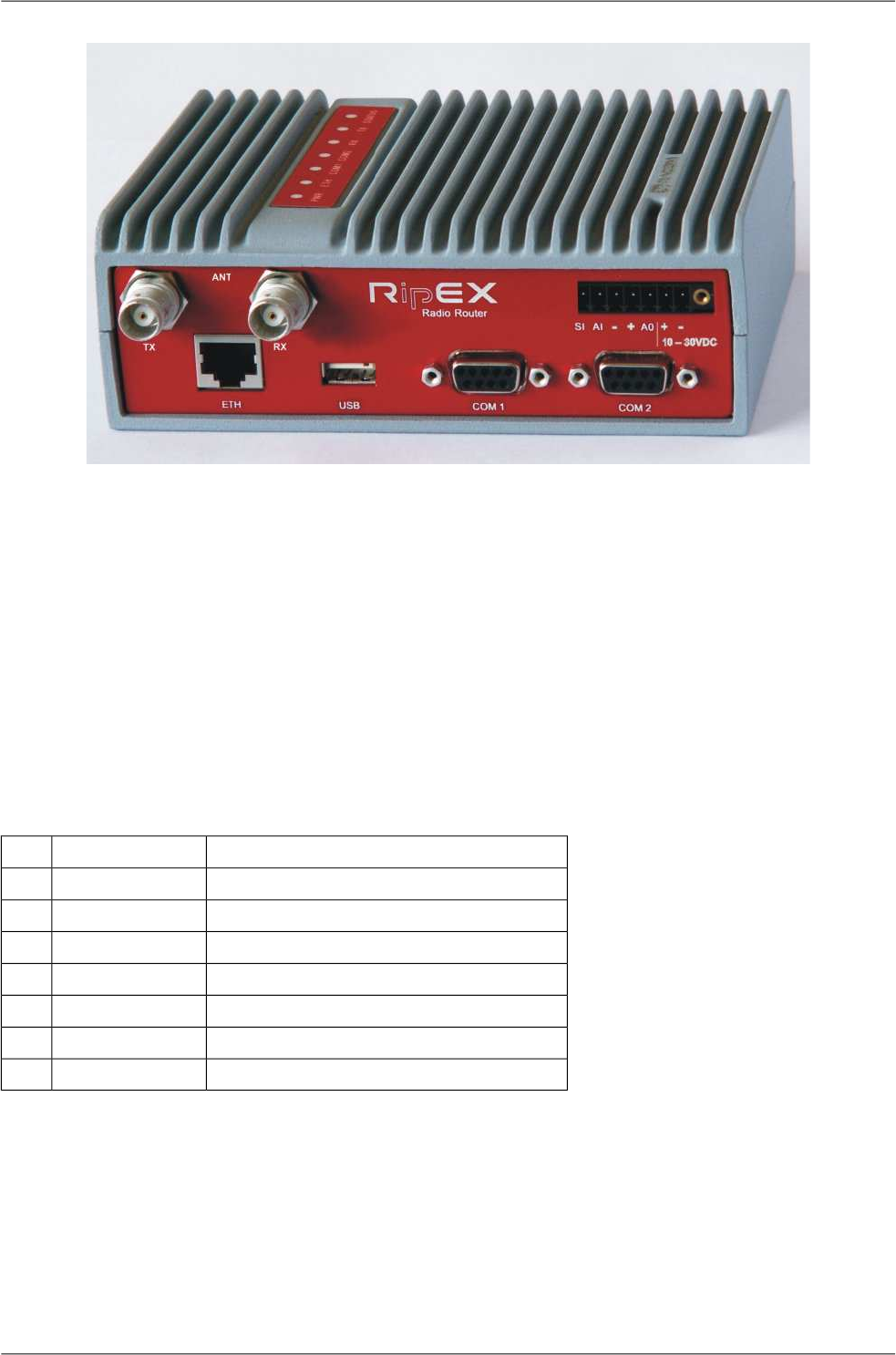
Fig. 4.5: Separated Rx and TX antennas
Warning: RipEX radio modem may be damaged when operated without an antenna or a dummy load.
4.2.2. Power and Control
This rugged connector connects to a power supply and it contains control signals. A Plug with screw-
terminals and retaining screws for power and control connector is supplied with each RipEX. It is Tyco
7 pin terminal block plug, part No. 1776192-7, contact pitch 3.81 mm. The connector is designed for
electric wires with a cross section of 0.5 to 1.5 mm2. Strip the wire leads to 6 mm (1/4 inch). Isolated
cables should receive PKC 108 or less end sleeves before they are inserted in the clip. Insert the cables
in the wire ports, tightening securely.
Tab. 4.1: Pin assignement
signallabeledpin
SLEEP INSI1
ALARM INAI2
−(GND) – for SLEEP IN, ALARM IN−3
+(PWR) – for ALARM OUT+4
ALARM OUTAO5
+PWR (10 to 30 V)+10–30VDC6
−PWR (GND)−10–30VDC7
Pins 3 and 7, 4 and 6 are connected internally.
39© RACOM s.r.o. – RipEX Radio modem & Router
Product
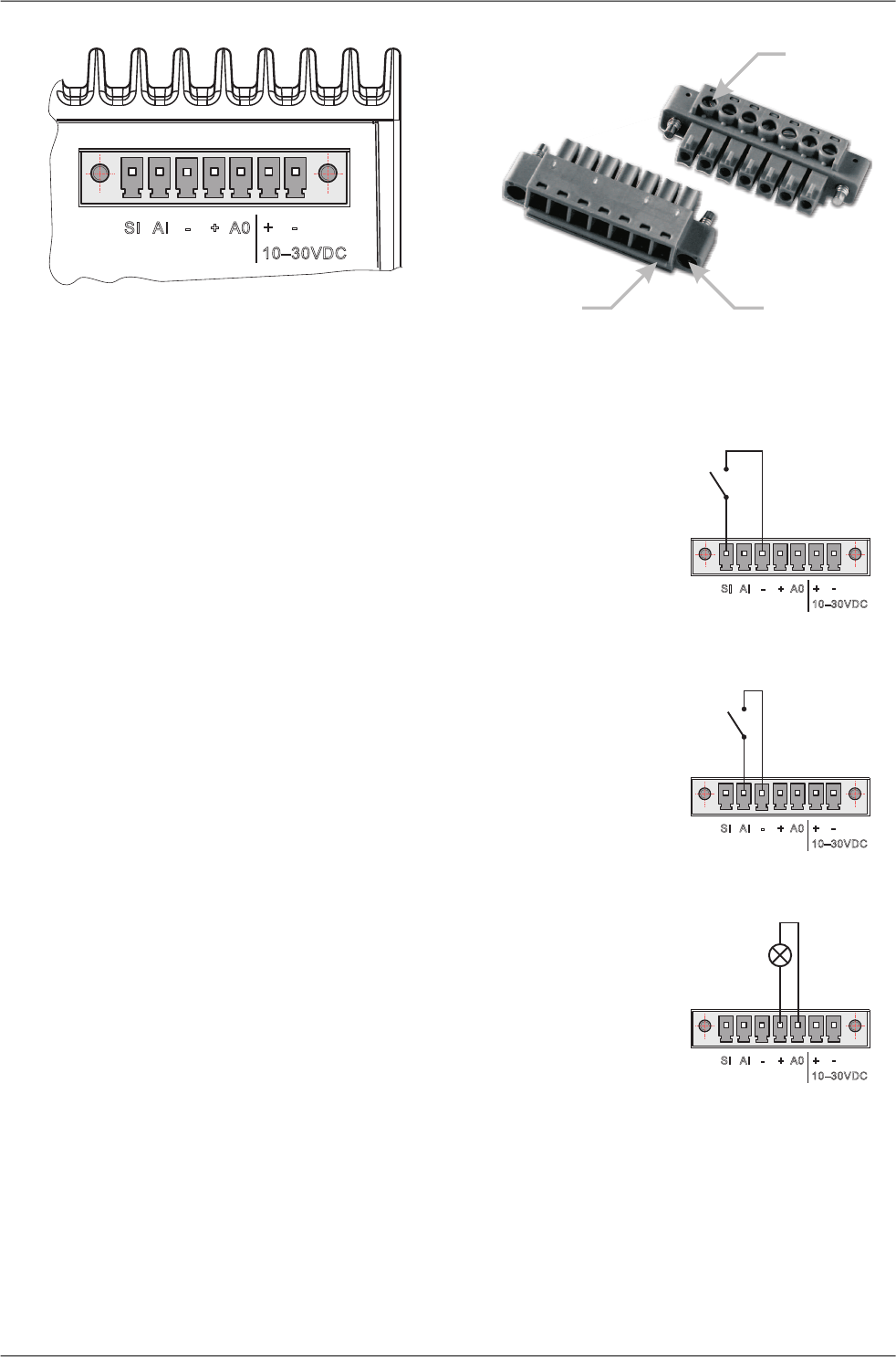
1 2 3 4 5 6PinNo.: 7
SI AI - + A0 +-
10–30VDC
Fig. 4.6: Supply connector
Wire
Ports(7)
Retaining
Screws(2)
Lead
Binding
Screws(7)
Fig. 4.7: Power and Control - cable plug
1 2 3 4 5 6PinNo.: 7
SI AI - + A0 +-
10–30VDC
SleepInput
SLEEP IN
SLEEP IN is the digital input for activating the Sleep mode. When
this pin is grounded (for example when connected to pin 3), the
RipEX switches into the Sleep mode. Using Power management
(Advanced Config.), the Entering the Sleep mode can be delayed
by a set time. Disconnecting SLEEP IN from GND (-) ends the
Sleep mode. Note that RipEX takes 25 seconds to wake up from
the Sleep mode.
1 2 3 4 5 6PinNo.: 7
SI AI - + A0 +-
10–30VDC
AlarmInput
ALARM IN
ALARM IN is a digital input. If grounded (e.g. by connecting to
PIN 3), an external alarm is triggered. This alarm can be used
for example to transmit information using SNMP trap, informing
for instance about a power outage or RTU problem. For details
about Alarm management see chapter Advanced Configuration.
1 2 3 4 5 6PinNo.: 7
SI AI - + A0 +-
10–30VDC
AlarmOutput
max.30VDC,1 A
ALARM OUT
ALARM OUT is a digital output. It can be activated in Alarm
management settings, chapter Advanced Configuration. It may
be used for instance to switch on the Fan kit if the preset maxim-
um internal temperature is exceeded or to inform the connected
RTU about a RipEX alarm. If an alarm is triggered, ALARM OUT
is internally connected to GND. If the external device requires
connection to positive terminal of the power supply, PIN 4 should
be used.
PWR
The PWR pins labelled + and - serve to connect a power supply 10–30 VDC. The requirements for a
power supply are defined in Section 6.6, “Power supply” and Section 4.4, “Technical specification”.
RipEX Radio modem & Router – © RACOM s.r.o.40
Product
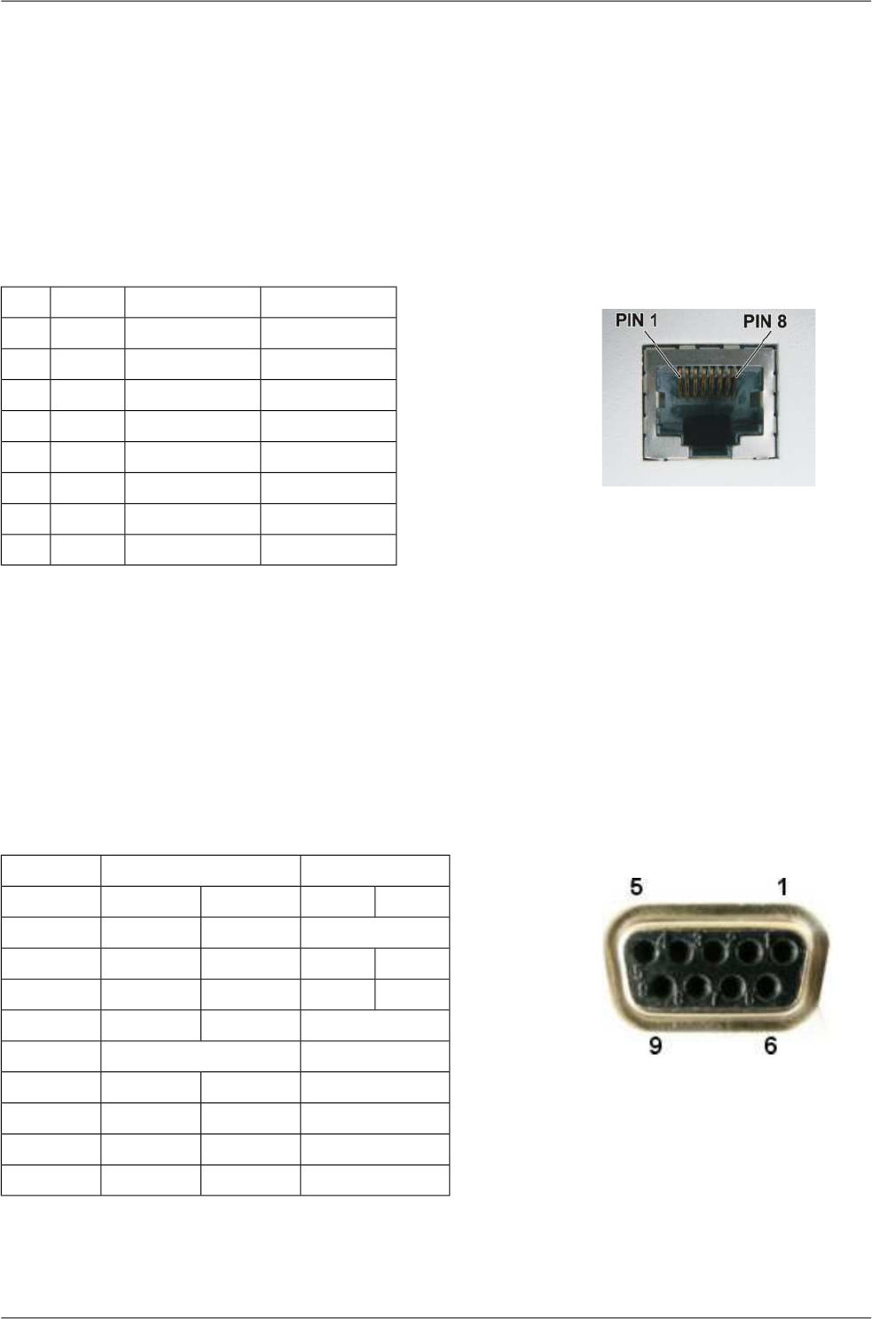
4.2.3. ETH
Standard RJ45 connector for ethernet connection. RipEX has 10/100 BaseT Auto MDI/MDIX interface
so it can connect to 10 Mbps or 100 Mbps ethernet network. The speed can be selected manually or
recognised automatically by RipEX. RipEX is provided with Auto MDI/MDIX function which allows it to
connect over both standard and cross cables, adapting itself automatically.
Pin assignement
Fig. 4.8: RJ-45F
Tab. 4.2: Ethernet to cable connector connections
Crossed cableDirect cableSignalPIN
green – whiteorange – whiteTX+1
greenorangeTX−2
orange – whitegreen – whiteRX+3
blueblue—4
blue – whiteblue – white—5
orangegreenRx−6
brown – whitebrown – white—7
brownbrown—8
4.2.4. COM1 and COM2
RipEX provides two serial interfaces COM1 and COM2 terminated by DSUB9F connectors. COM1 is
always RS232, COM2 can be configured as RS232 or RS485 (more in Adv. Conf., COM's).
RipEX‘s RS232 is a hard-wired DCE (Data Communication Equipment) device. Equipment connected
to the RipEX’s serial ports should be DTE (Data Terminal Equipment) and a straight-through cable
should be used. If a DCE device is connected to the RipEX‘s serial ports, a null modem adapter or
cross cable has to be used.
Fig. 4.9: Serial connector
Tab. 4.3: COM1,2 pin description
COM2 – RS485COM1, 2 – RS232DSUB9F
In/ OutsignalIn/ Outsignalpin
—OCD1
I/Oline BORxD2
I/Oline AITxD3
—IDTR4
GNDGND5
—ODSR6
—IRTS7
—OCTS8
———9
RipEX keeps pin 6 DSR at the level of 1 by RS232 standard permanently.
41© RACOM s.r.o. – RipEX Radio modem & Router
Product
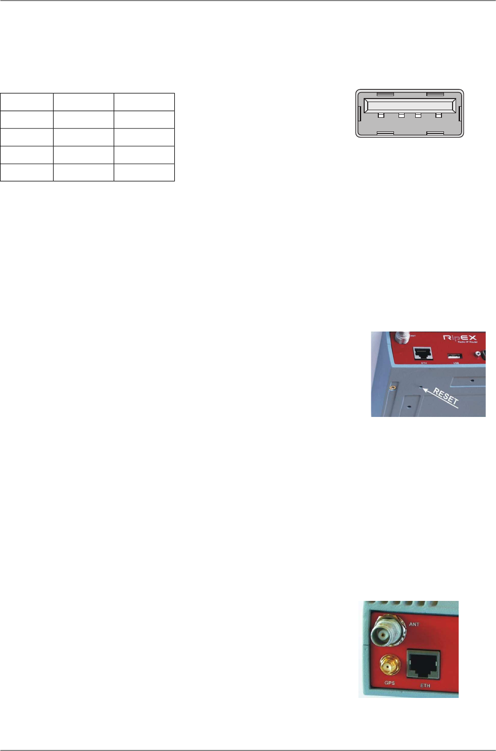
4.2.5. USB
RipEX uses USB 1.1, Host A interface. USB interface is wired as standard:
1 2 3 4
Fig. 4.10: Serial connector
Tab. 4.4: USB pin description
wiresignalUSB pin
red+5 V1
whiteData(−)2
greenData (+)3
blackGND4
The USB interface is designed for the connection to the "X5" – external ETH/USB adapter. The "X5"
is an optional accessory to RipEX, for more see Section 5.3, “Connecting RipEX to a programming
PC”. The adapter is used for service access to RipEX’s web configuration interface.
The USB connector also provides power supply (5 V/ 0.5 A). It can be used to temporarily power a
connected device, for instance a telephone. The USB connector should not be used as permanent
source of power supply.
4.2.6. Reset button
Fig. 4.11: Reset
RipEX’s bottom-side enclosure includes a reset button accessible through
an opening. When this button is pressed, the STATUS diode on the LED
panel goes dark (indicating that the button has been pressed). If you hold
the button for 5 seconds, the STATUS diode starts flashing slowly indicat-
ing that the reset is complete. If you continue to hold the button for 15 or
more seconds (the STATUS diode starts flashing quickly) and then release
it, you will reset the device’s access information to default: parameters
such as the login, password and ethernet IP will be reset to their defaults.
Resetting access parameters to defaults also sets the Ethernet speed to
„Auto“ and results in clearing all firewall rules (which may have been
blocking the access by accident). Remember to re-install your firewall if you are using one.
Note
To reset the RipEX only use the RESET button as described above or use the button in RipEX’s web
configuration, see Adv. Conf., Maintenance. Never use a power cycling (disconnecting and reconnecting
power supply) to reset it. While power cycle resets, or rather reboots the RipEX, its software will not
terminate correctly resulting in logs, statistics and graphs not being saved properly.
4.2.7. GPS
Fig. 4.12: GPS Connector SMA
RipEX can be equipped with an internal GPS, see Section 4.5,
“Model offerings”. The GPS module is used for time synchronisation
of the NTP server inside RipEX. See Adv. Conf., Time for more. In
this case the front panel contains a SMA female 50 ohm connector
for connecting the GPS antenna.
RipEX Radio modem & Router – © RACOM s.r.o.42
Product
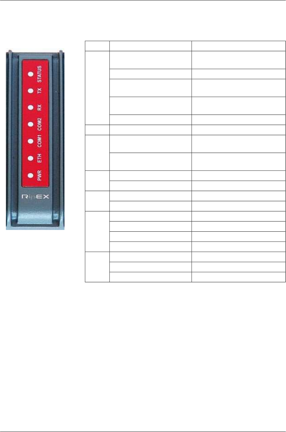
4.3. Indication LEDs
Fig. 4.13: Indication LEDs
Tab. 4.5: Key to LEDs
DescriptionColor
The RipEX OS (Linux) is running
succesfuly
Green
STATUS
Reset button has been pressedDark
reset after five-seconds pressing
the Reset button
Green flashes slowly
default access after 15-seconds
pressing the Reset button
Green flashes quickly
Status alarmRed
transmitting to radio channelRedTX
receiver is synchronised to a
packet
Green
RX there is a signal stronger than
−80 dBm on Radio channel
Yellow
data receivingGreen
COM2 data transmittingYellow
data receivingGreen
COM1 data transmittingYellow
100 Mb/s speedYellow ON
ETH 10 Mb/s speedYellow OFF
connectedGreen ON
ethernet dataGreen flashes
powered succesfulyGreen
PWR Save modeBlinks with a period of 1 sec
Sleep modeFlashes once per 3 sec
43© RACOM s.r.o. – RipEX Radio modem & Router
Product