RadioFrame Networks SSEROMNICELLH S-Series OmniCell@Home User Manual RadioFrame Networks
RadioFrame Networks, Inc S-Series OmniCell@Home RadioFrame Networks
Contents
- 1. User Manual 1
- 2. User Manual 2
User Manual 1

CONFIDENTIAL AND PROPRIETARYSUPPLIER AND CUSTOMER INFORMATION RadioFrame Networks, Inc.
RadioFrame Networks
S-Series OmniCell@Home Picocell
GSM Implementation Guide
July 2, 2008
998-1027-01 Rev X2

Revision History S-Series OmniCell@Home Picocell GSM Implementation Guide 998-1027-01 Rev X2
Service Information
Operation is subject to the two following conditions: This device may not cause harmful interference, and this
device must accept any interference received, including interference that may cause undesired operation. <<<TO
BE CONFIRMED BEFORE PUBLICATION This equipment has been tested and found to comply with the limits
pursuant to Parts 22 and 24 of the FCC Rules. These limits are designed to provide reasonable protection against
harmful interference when the equipment is operated in a commercial environment.>>>
Copyrights and Trademarks
RadioFrame Networks is a trademark or service mark, and RadioFrame, RadioBlade and the RadioFrame
Networks logo are registered trademarks of RadioFrame Networks, Inc. You may not use these or any other
RadioFrame Networks trademarks or service marks without the written permission of RadioFrame Networks, Inc.
All third-party product names and services are the property of their respective owners.
Throughout this publication, the terms RadioFrame Networks, RadioFrame and RFN signify RadioFrame Networks,
Inc.
S-Series OmniCell@Home Picocell GSM Implementation Guide
© Copyright 2008 RadioFrame Networks, Inc. All Rights Reserved. No part may be reproduced, in any media,
except as authorized by written permission of RadioFrame Networks, Inc.
ii CONFIDENTIAL AND PROPRIETARY RadioFrame Networks, Inc.
Revision History
Date Rev Notes
May 24, 2008 x Preliminary
June 25, 2008 x1 Remove commissioning artifact
July 2, 2008 x2 Correct compliance statement
Submit comments and corrections to:
RadioFrame Networks, Inc.
Technical Information Department
9461 Willows Road NE
Suite 100
Redmond, WA 98052
Tel.: +1 425 278 2780 Fax: +1 425 278 2781
http://www.radioframenetworks.com
E-mail techinfo@radioframenetworks.com
Once released, this document is posted as a .pdf file at:
http://www.radioframenetworks.com/support/

S-Series OmniCell@Home Picocell GSM Implementation Guide 998-1027-01 Rev X2
Table of Contents
1Introduction ............................................................................................................................................... 6
1.1System Definition ................................................................................................................................ 6
1.2Document Scope ................................................................................................................................. 7
1.3General Safety Information ................................................................................................................. 7
1.3.1Confirmation of Conformance to National Regulation .................................................................. 7
1.3.2Static Sensitive Precautions ......................................................................................................... 7
1.3.3Safety Warnings ........................................................................................................................... 7
1.3.4Recommendations ....................................................................................................................... 8
1.4Repair and Technical Support ............................................................................................................. 8
1.4.1Technical Support ........................................................................................................................ 8
1.4.2Field Replaceable Unit (FRU) Policy ............................................................................................ 9
2System Description ................................................................................................................................... 9
2.1Three-Domain Architecture ................................................................................................................. 9
2.1.1Internet Service Provider (ISP) Customer-Premise Domain ...................................................... 10
2.1.2Backhaul Domain ....................................................................................................................... 10
2.1.3Carrier Infrastructure Domain ..................................................................................................... 10
2.2PicoBTS Functional Block Diagram .................................................................................................. 11
2.3System Manager Software ................................................................................................................ 12
2.4Network Integration ........................................................................................................................... 12
3Specifications ......................................................................................................................................... 13
3.1Dimensions ........................................................................................................................................ 13
3.2Weight ............................................................................................................................................... 13
3.3Power Supply .................................................................................................................................... 13
3.4Output Power .................................................................................................................................... 15
3.5Power Control .................................................................................................................................... 15
3.6Typical Coverage Area ...................................................................................................................... 15
3.7Heat Load .......................................................................................................................................... 15
3.8RF Performance ................................................................................................................................ 15
3.8.1Spurious RF Emissions .............................................................................................................. 16
3.8.2Operating Frequency Bands ...................................................................................................... 16
3.8.3Transmitter Performance Summary ........................................................................................... 17
3.8.4Receiver Performance Summary ............................................................................................... 17
3.9Environmental Specifications ............................................................................................................ 18
3.10Safety and Compliance Specifications ....................................................................................... 19
3.11Antennas .................................................................................................................................... 19
3.12Logical Channels ........................................................................................................................ 19
3.13Services ...................................................................................................................................... 20
4Installation .............................................................................................................................................. 20
4.1Dimensioning Considerations ........................................................................................................... 20
4.1.1CPE Scaling ............................................................................................................................... 20
4.1.2Link Dimensioning ...................................................................................................................... 20
4.2Preparation for Installation ................................................................................................................ 21
4.3Installing CPE Equipment.................................................................................................................. 21
4.3.1Mechanical Installation Time ...................................................................................................... 21
4.3.2Bringing up the PicoBTS ............................................................................................................ 22
5Scheduled and Unscheduled Maintenance ............................................................................................ 23
5.1Maintenance ...................................................................................................................................... 23
5.1.1Customer Domain Component (PicoBTS) ................................................................................. 23
5.2Troubleshooting Guidelines .............................................................................................................. 23
5.2.1Fault Indications ......................................................................................................................... 23
5.2.2System Manager Alarms ............................................................................................................ 23
RadioFrame Networks, Inc. SUPPLIER AND CUSTOMER INFORMATION iii

998-1027-01 Rev X2 S-Series OmniCell@Home Picocell GSM Implementation Guide
5.2.3Serial Log Upload Procedure .................................................................................................... 23
5.2.4Power Down Procedure ............................................................................................................. 23
5.2.5Field Replaceable Unit (FRU) Procedures ................................................................................ 23
6System Configuration Changes ............................................................................................................. 23
6.1Adding S-Series Components .......................................................................................................... 24
6.2Spares, Parts and Suppliers ............................................................................................................. 24
Appendix A.Definitions and Abbreviations .............................................................................................. 25
Appendix B.Default Configuration of the OmniCell@Home Picocell as Shipped ................................... 27
Appendix C.RF Emissions Precautions .................................................................................................. 28
C.1Exposure vs. Frequency ................................................................................................................... 28
Appendix D.Communication Interconnects ............................................................................................. 29
iv CONFIDENTIAL AND PROPRIETARY RadioFrame Networks, Inc.

S-Series OmniCell@Home Picocell GSM Implementation Guide 998-1027-01 Rev X2
RadioFrame Networks, Inc. SUPPLIER AND CUSTOMER INFORMATION v
Figures
Figure 1 OmniCell@Home Picocell Base-Transceiver Station (PicoBTS) ................................................... 6
Figure 2 S-Series Architecture ................................................................................................................... 10
Figure 3 PicoBTS Functional Block Diagram ............................................................................................. 12
Figure 4 PicoBTS Router Configuration Page ............................................................................................ 22
Tables
Table 1 FRU Table ....................................................................................................................................... 9
Table 2Dimensions .................................................................................................................................. 13
Table 3Weight .......................................................................................................................................... 13
Table 4 Power Supply Electrical Requirements ......................................................................................... 13
Table 5 Power Supply Mechanical Requirements ...................................................................................... 14
Table 6 Power Supply Safety Requirements .............................................................................................. 14
Table 7 Power Supply Environmental Requirements ................................................................................. 14
Table 8 Power Requirements ..................................................................................................................... 15
Table 9 Heat Load ...................................................................................................................................... 15
Table 10 Transmit and Receive Frequency Ranges .................................................................................. 16
Table 11 Spacing for ARFCN Pairing ......................................................................................................... 16
Table 12 Transmitter Performance Summary ............................................................................................ 17
Table 13 Receiver Performance Summary ................................................................................................ 17
Table 14 Environmental Specifications ...................................................................................................... 18
Table 15Safety and Compliance Specifications <<<PENDING>>> ......................................................... 19
Table 16 ...................................................................................................................................... 19Antennas
Introduction S-Series OmniCell@Home Picocell GSM Implementation Guide 998-1027-01 Rev X2
1 Introduction
1.1 System Definition
The RadioFrame
®
Networks OmniCell@Home™ picocell is a modular radio solution that
provides flexible and efficient software-driven base stations for Mobile Network Operators
(MNO) that need to deploy cost-effective radio access in small, inexpensive increments.
Unlike traditional approaches from vendors offering proprietary, single-technology
equipment, RadioFrame Networks offers an agile, multiple-technology, future-proof
solution that integrates into the existing Radio Access Network (RAN) reducing capital
expenditure.
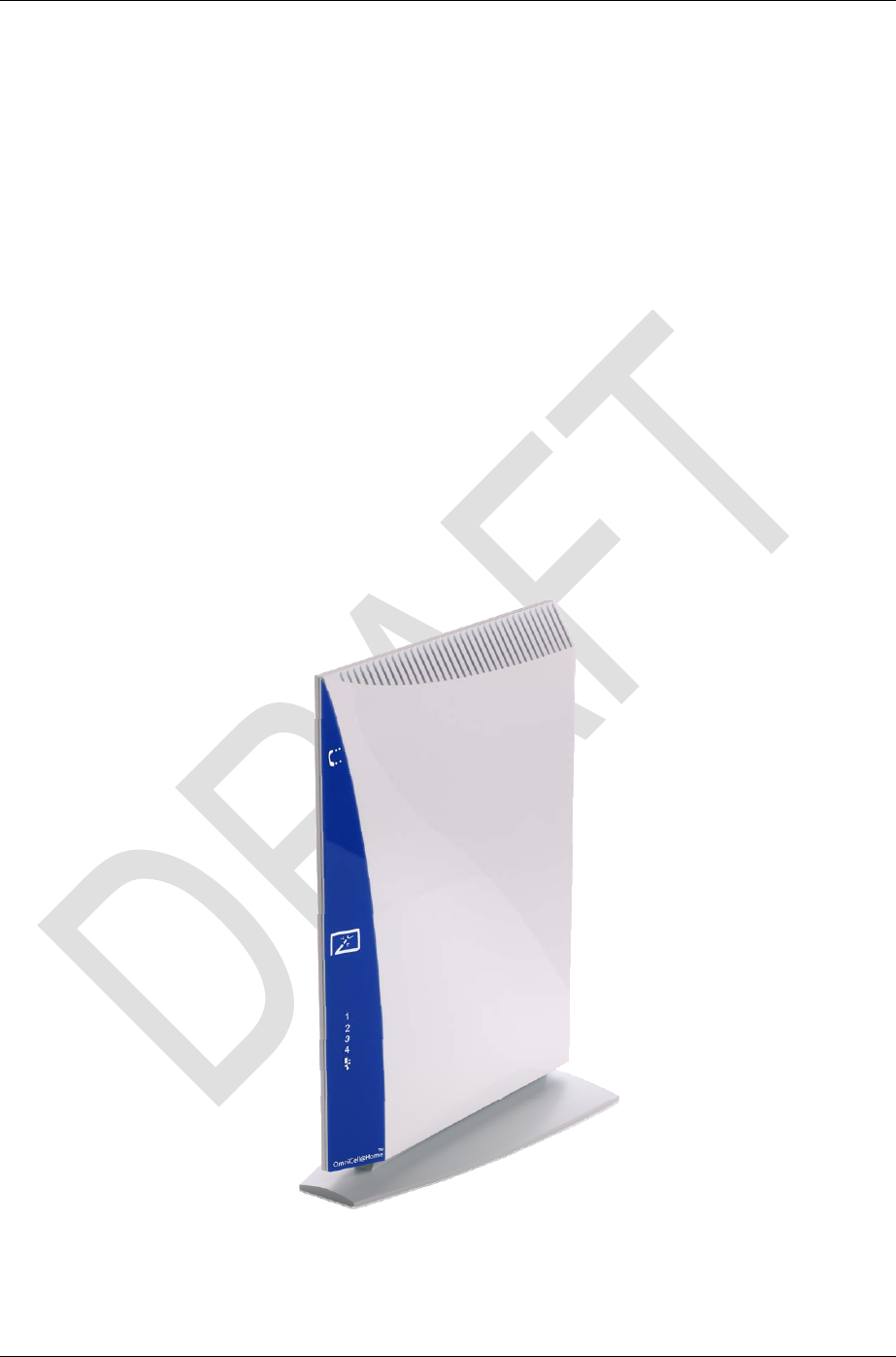
The OmniCell@Home picocell base-transceiver station (PicoBTS), shown in Figure 1,
reduces operating costs associated with expensive, dedicated E1/T1 leased lines by
making use of DSL and cable broadband packet-switched networks for backhaul between
the customer premises and the mobile operator network.
Figure 1 OmniCell@Home Picocell Base-Transceiver Station (PicoBTS)
6 CONFIDENTIAL AND PROPRIETARY RadioFrame Networks, Inc.

S-Series OmniCell@Home Picocell GSM Implementation Guide Introduction
998-1027-01 Rev X2
1.2 Document Scope
This document covers installation and configuration of the OmniCell@Home base-
transceiver station, often referred to as Customer-Premise Equipment (CPE). The
Network Elements (NEs) are addressed in other documents in the OmniCell@Home S-
Series System Document Set as follows:
• <<To Be Supplied>>
1.3 General Safety Information
Read all the notices in this section prior to installing or using the S-Series system or any
of its components.
1.3.1 Confirmation of Conformance to National Regulation
The S-Series equipment complies with the provisions of the European R&TTE Directive
(99/05/EC). Declaration of conformity may be obtained from RadioFrame; Compliance
Engineering Department; 9461 Willows Road NE, Suite 100; Redmond, WA 98052, USA.
1.3.2 Static Sensitive Precautions
Electrostatic discharge (ESD) can damage equipment and impair electrical circuitry. It
occurs when electronic printed circuit cards are improperly handled and can result in
complete or intermittent failures.
• Prior to handling, shipping, and servicing equipment, always put on a conductive
wrist strap connected to a grounding device to discharge any accumulated static
charges. All RFN FRUs ship with a disposable anti-static wrist strap.
Warning!
Use extreme caution when wearing a conductive wrist strap near sources of high
voltage. The low impedance provided by the wrist strap also increases the danger
of lethal shock should accidental contact with high voltage sources occur.
• Place FRUs only on an anti-static mat when removed from the system. The
conductive surface must be connected to ground through 100 kΩ.
• Do not use non-conductive material for packaging FRUs for shipment or storage.
Wrap all FRUs with anti-static (conductive) material.
• If possible, retain all original packing material for future use.
1.3.3 Safety Warnings
Warning!
Ultimate disposal of this product should be handled according to all national laws
and regulations.
Warning!
The user is cautioned that changes or modifications made to the equipment that
are not expressly approved by the party responsible for compliance, could void
the user’s authority to operate the equipment.
RadioFrame Networks, Inc. SUPPLIER AND CUSTOMER INFORMATION 7

Introduction S-Series OmniCell@Home Picocell GSM Implementation Guide 998-1027-01 Rev X2
Warning!
To ensure FCC compliance of this equipment, it is the user’s responsibility to
obtain and use only shielded and grounded interface cables.
Warning!
Customer-premise equipment (CPE) emits RF. Protection stipulations were
required as a condition of qualification for the CE mark. It is the responsibility of
the supplier to the end user to provide information necessary for installation and
operation of CPE in accordance with the European R&TTE Directive (99/05/EC)
with regard to safety. The following statement (or expression to its effect) must
accompany CPE delivered to the end user:
This equipment emits radio-frequency (RF) energy. For compliance with
European directives regarding RF exposure, the manufacturer has determined
that to prevent sustained RF exposure, the equipment must be installed such that
persons maintain at least twenty (20) cm clearance.
1.3.4 Recommendations
• Do not work alone if potentially hazardous conditions exist.
• Never assume that power is disconnected from a circuit. Always check.
• Look carefully for possible hazards in the work area, such as moist floors,
ungrounded extension cables, frayed power cords and missing safety grounds.
1.4 Repair and Technical Support
RadioFrame Networks provides technical support services to the supplier of the S-Series
system and its components, which is Nokia Siemens Networks (NSN).
The NSN Helpdesk service, sometimes referred to as End-to-End Customer Care (ECC),
is operational Monday-Friday, 0900 to 1700 hrs GMT.
The service is for reporting of faults that are of a non-urgent nature, i.e., non-service-
affecting, limited impact, etc.
Faults can be logged via telephone, e-mail and Nokia Online Services (NOLS).
1.4.1 Technical Support
The following methods can be used to submit a request into the NOLS support pipeline:
• Internet www.online.nsn.com
• Telephone 0800 421321, option 1
• E-mail NET.contactcentre.EUR1@nokia.com
Please have the following information available when submitting a case into the support
pipe:
• Company
•
Severity
• Affected Network Element
•
Detailed Description
• Request Type (SW/HW etc.)
•
Contact Person/details
• SW Release/CD Level
•
Customer reference ID
8 CONFIDENTIAL AND PROPRIETARY RadioFrame Networks, Inc.

S-Series OmniCell@Home Picocell GSM Implementation Guide System Description
998-1027-01 Rev X2
1.4.2 Field Replaceable Unit (FRU) Policy
The S-Series system has been designed so that Field Repairable Units (FRUs) can be
replaced to restore normal system operation as quickly as possible. RadioFrame
Networks components are individually tested prior to shipment.
If RadioFrame Networks equipment should require service or repair, note the requested
information from Section 1.4.1, and then contact the NSN ECC.
Note: Do not attempt to repair RadioFrame Networks equipment and components
in the field.
Note: Always use a static grounding wrist strap before handling any chassis.
• Include the serial numbers of the affected equipment.
• Give a clear return address, including:
Name
Address, including building or Suite #
Postal code
Contact phone number
Alternate Contact phone number
• Securely package the FRU in its original shipping carton, if available. Otherwise,
package in a static protection bag in a well-padded carton.
Table 1 lists current FRU equipment for the S-Series system. Refer to the table for
replacing any of the following equipment. For equipment not supplied by RadioFrame,
follow standard policies and procedures for FRU replacement of that equipment.
Table 1 FRU Table
Nokia PN RadioFrame PN Nokia Name Description
471444A.101 176-0110-Rxx SBTA Nokia Pico GSM/EDGE BTS
ANSI Band
PicoBTS, North American,
Lead Free
471644A.101 176-0125-Rxx SBTE Nokia Pico GSM/EDGE BTS
ETSI Band
PicoBTS, European, Lead
Free
083950A.101 176-0208-Rxx SPSM Nokia Pico GSM/EDGE PSM FRU, Power Supply,
PicoBTS
2 System Description
The S-Series system is a picocell base-transceiver station (BTS) solution that provides
radio coverage in small footprint increments with low additional cost.
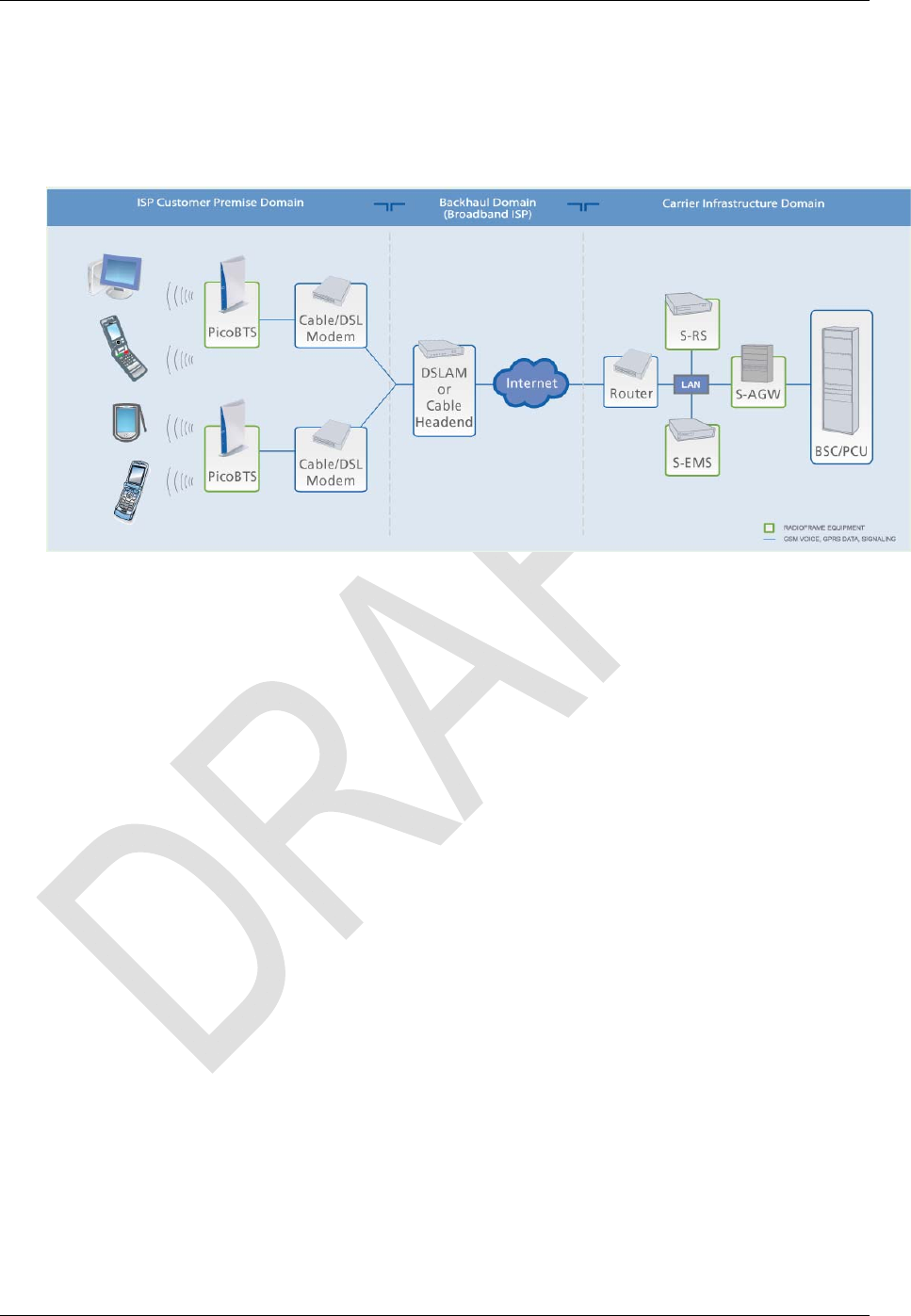
2.1 Three-Domain Architecture
The OmniCell@Home picocell interoperates with aggregating nodes in the BSS to
optimize BSC resource utilization. The S-Series components, shown in Figure 2, include
the OmniCell@Home Base Transceiver Station (PicoBTS), which provides coverage in
the customer premises, the S-Series Registration Server (S-RS), which provides a
mechanism for authenticating each PicoBTS, the Element Management System (S-EMS),
which manages operation of the network elements, and the Aggregation Gateway (S-
RadioFrame Networks, Inc. SUPPLIER AND CUSTOMER INFORMATION 9
System Description S-Series OmniCell@Home Picocell GSM Implementation Guide 998-1027-01 Rev X2
10 CONFIDENTIAL AND PROPRIETARY RadioFrame Networks, Inc.
AGW), which presents the Abis interface to the Base Station Controller (BSC) and Packet
Control Unit (PCU) in the Base Station System (BSS).
Figure 2 S-Series Architecture
2.1.1 Internet Service Provider (ISP) Customer-Premise Domain
The Customer-Premise Domain consists of small form factor PicoBTSs with DSL and/or
cable modem/router connections to the Backhaul Domain. Each PicoBTS is connected to
the DSL/cable modem/router via an RJ-45 CAT5 Ethernet cable.
• Connection to the Backhaul Domain may alternatively be provided through a
customer-premise LAN
• PicoBTSs are distributed in the customer premises to optimize coverage
• Each PicoBTS acts as a single picocell
2.1.2 Backhaul Domain
The Backhaul Domain provides secure transport between the PicoBTSs and the S-AGW
in the Infrastructure Domain. The Backhaul IP Domain must also include a local DHCP
server or access to a DNS server.
The backhaul domain link must meet minimum performance requirements.
2.1.3 Carrier Infrastructure Domain
The Infrastructure Domain consists of a mobility network and optionally a separate data
network that provides access to the Internet. Common to both networks is a firewall
(optional).
The S-AGW manages system resources and multiplexes/de-multiplexes user traffic to
multiple RadioFrame customer-premise PicoBTSs. Each PicoBTS is configured to be a
logical 1-TRX Metro-Site BTS from the BSC’s point of view.
Note: The Transcoder Rate Adaptation Unit (TRAU) function is required, as it is for an
existing GSM BTS.

S-Series OmniCell@Home Picocell GSM Implementation Guide System Description
998-1027-01 Rev X2
The S-RS provides a mechanism for authenticating each S1 BTS as it joins the service-
provider (SP) network (during system start-up) and initial key exchange for protection of
subsequent signalling communications between the PicoBTS and the S-AGW. In
essence, the S-RS serves as a “gatekeeper” – ensuring that only authenticated PicoBTS
equipment may reach the S-AGW via its backhaul IP address.
The S-EMS is used to manage the operation of the S-Series AGW and PicoBTS network
elements. The S-EMS performs typical Element Manager Layer (EML) services as
defined by the Telecommunications Management Network (TMN) model. The S-EMS
provides management functions in addition to the GSM management provided by the
MNO’s existing OMC across the Abis interface.
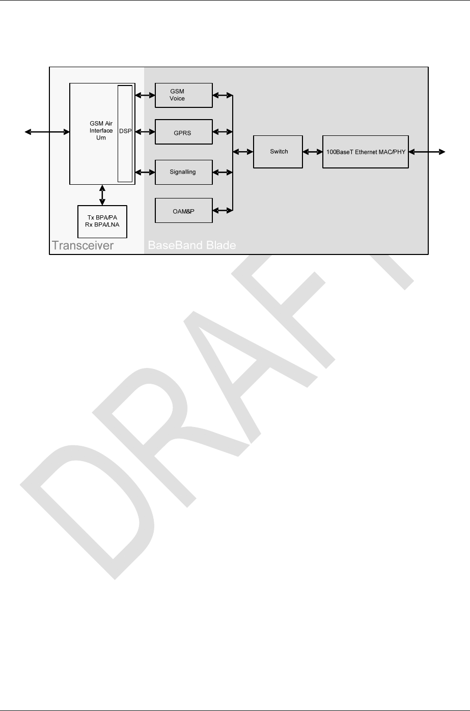
2.2 PicoBTS Functional Block Diagram
Figure 3 shows the functional subsystems of the PicoBTS. These are described in the
following paragraphs.
RF Monitor
The RF monitor functional block is a GSM receiver capable of receiving in the 900/1800
and 850/1900 bands. The purpose of this block is to monitor the radio environment and
look for carriers from the macro network as well as carriers from other nearby PicoBTS
units. Signal information from these sources is passed to the Host CPU block where it is
used for frequency planning and other system-management functions.
EDGE/GPRS/GSM
This block is the PicoBTS quad-band transceiver. It performs the radio functions required
in a base station as well as baseband processing of transmitted and received signals.
Though not strictly part of the transceiver, the SIM-card reader is included in this block as
it interfaces directly to the FPGA.
Host CPU
This block performs a variety of control and processing functions necessary for operation
of the HRBS. The WLAN transceiver, router, GSM transceiver and RF monitoring
sections interface to the host CPU.
Router and Ethernet PHY
In addition to providing LAN capability, the router section allows additional Ethernet
connections to the ISP network.
RadioFrame Networks, Inc. SUPPLIER AND CUSTOMER INFORMATION 11
System Description S-Series OmniCell@Home Picocell GSM Implementation Guide 998-1027-01 Rev X2
Figure 3 PicoBTS Functional Block Diagram
2.3 System Manager Software
Management is primarily intended to be performed using existing Operation Support
System (OSS) resources within the MNO infrastructure. However, there are also local
and remote management capabilities provided by the System Manager software
package. System Manager is a web-based graphical management system, which is
accessible via an IP-based connection.
System Manager provides Operations personnel with remote access and control,
including configuration, alarm monitoring, triage/troubleshooting and system statistical
reporting. All S-Series systems include System Manager as standard equipment. Core
System Manager functions include:
• Software Download (both locally and remotely)
• X.733 Alarming
• Configuration Management
• Diagnostics and Troubleshooting
• Call Statistics and Uptime
• RF Performance Metrics (e.g., Uplink SQE, Noise Floor, etc.)
• Test and Maintenance (e.g., automated BER testing)
2.4 Network Integration
To support needed personalization and location features, the S-Series communicates
with one or more of the databases (such as Personalization and Location DBs) which
may or may not already exist in the Mobile Network Operator (MNO) BSS and CN.
Each PicoBTS is equipped with a SIM card that stores necessary information for S-Series
provisioning and authentication. SIM-based authentication methodology, similar to GSM
authentication but with no core-network involvement, is used during the PicoBTS
registration with the S-RS to ensure that stolen PicoBTSs are barred from operating. The
PicoBTS authentication does not involve the HLR or any other core-network (CN)
element.
12 CONFIDENTIAL AND PROPRIETARY RadioFrame Networks, Inc.
S-Series OmniCell@Home Picocell GSM Implementation Guide Specifications
998-1027-01 Rev X2
The existing BSC and BTS MIBs can be managed by the existing BSS OMC, and the
additional PicoBTS MIBs can be managed by the new S-EMS (a separate NE) or these
MIBs can be integrated into the OMC. One common scenario is to initially deploy a single
S-EMS and then remove it once the integration of the S-Series with standard MNO
element and network management resources is completed.
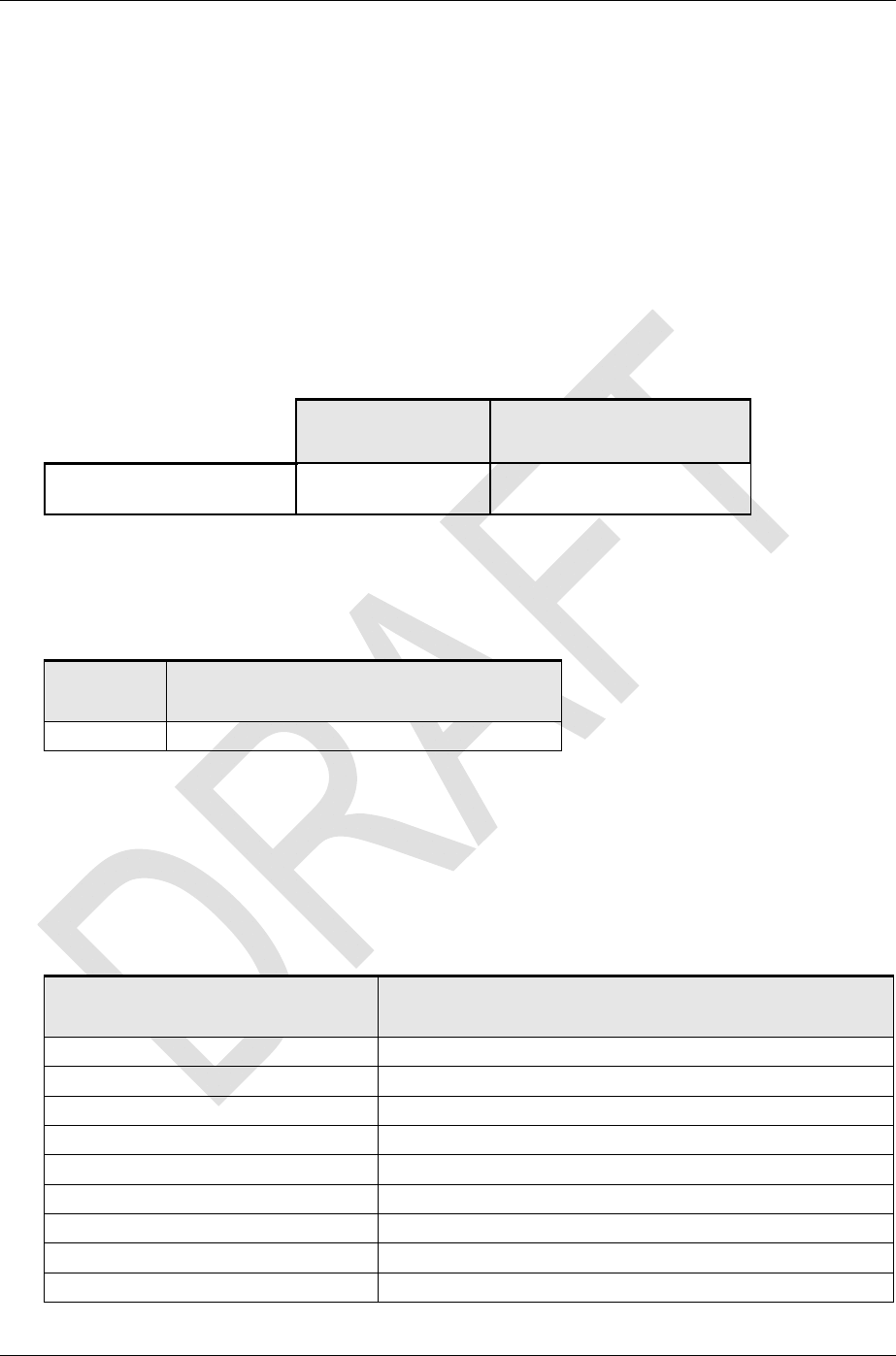
3 Specifications
3.1 Dimensions
Table 2 Dimensions
Metric (w x h x d cm) Imperial (w x h x d in.)
PicoBTS Volume
(approximate form factor) 26.7 x 18.9 x 4.4 10.6 x 7.5 x 1.8
3.2 Weight
Table 3 Weight
Unit Estimated Weight
PicoBTS Inclusive of power supply: 1 kg
3.3 Power Supply
The PicoBTS operates on a single nominal 12 VDC, 1.25 A supply. The electrical
characteristics of the power supply and the input power requirements of the PicoBTS are
listed in Table 4.
Table 4 Power Supply Electrical Requirements
Spec Value
Input Voltage 90-264 VAC
Input Current < 0.6 A RMS Max
Input Frequency 47 - 63 Hz
Output Voltage / Current 12 VDC @1.25 A
Output Current No Load to Full Load, No Minimum Load Required
Output Power (Rated) 18 Watts Max
Output Ripple (Peak to Peak) <150 mV
Output Regulation (Line/Load) + 5% for Main Output, Measured at O/P Connector
Line Regulation + 1% Max at Full Load
RadioFrame Networks, Inc. SUPPLIER AND CUSTOMER INFORMATION 13

Specifications S-Series OmniCell@Home Picocell GSM Implementation Guide 998-1027-01 Rev X2
14 CONFIDENTIAL AND PROPRIETARY RadioFrame Networks, Inc.
Spec Value
Hold-up Time >10 ms Min at Nominal Input and Full Load
Inrush Current Inrush Limiting
Ove
r
-Current / Short Circuit Auto Recovery
Dielectric Withstand Voltage 3000 VAC Primary-Secondary
Leakage Current < 1 mA
Line Surge EN 61000-4-5 Level 4
Table 5 Power Supply Mechanical Requirements
Spec Value
Housing High Impact Plastic, 94V0 Polycarbonate, Non-vented, Color
Black
Size, Max., Any Dim. 100 mm
Cooling Convection
Weight <350 g
Output Connecto
r
Center Positive, 2.5 mm Barrel
Input Connecto
r
Shaver C8; or Molded AC Cable Included, Country Specific
Table 6 Power Supply Safety Requirements
Spec Value
Other Protection Input Fusing
Safety Approvals UL60950, CUL TO 22.2# 950, SEMKO TO EN60950, CCC TO
GB4943-2001, GB9254-1998, GB17625.1-2003, CE CLASS II,
AS/NZ 60950, PSE TO J60950, CB REPORT
Table 7 Power Supply Environmental Requirements
Spec Value
ROHS Compliant
WEEE Compliant
MTBF 50,000 hours
Operating Temperature 0°C to 40° C
Storage Temperature –40°C TO 80° C
Humidity 0% TO 90% Relative Humidity
EMI EN550022 Class B, EN61000-3-2, EN61000-3-3
Immunity EN55024:1998

S-Series OmniCell@Home Picocell GSM Implementation Guide Specifications
998-1027-01 Rev X2
Table 8 Power Requirements
Min Nom Max Units Comments
Operational 11.4 12 12.6 VDC Required range for normal operation of the
PicoBTS
Operational 1.43 1.25 1.58 A
Operational 8.3 – 13.2 VDC
PicoBTS will power up, but may not function
properly
Operational 1.36 – 2.17 A
Absolute Max – – 15 VDC
Exceeding may cause permanent damage
Absolute Max – – 2.2 A
Absolute Min 7.9 – – VDC
Below this voltage the PicoBTS will not power up
Absolute Min 1.2 – – A
3.4 Output Power
The PicoBTS is configured for an output power of:
• GMSK +23 dBm max
• 8-PSK +15 dBm max
3.5 Power Control
Transmit power control is statically provisioned in 2 dB ± 1 dB steps according to GSM
05.05, sub clause 4.1.2.
3.6 Typical Coverage Area
The typical coverage radius measures approximately 50 m. Nominal coverage per
PicoBTS is 6,360 sq m (70,000 sq ft).
3.7 Heat Load
Table 5 identifies the heat load for a functional PicoBTS.
Table 9 Heat Load
Component Heat Load
(W) (BTU per Hour)
PicoBTS 18 61.45
3.8 RF Performance
The PicoBTS employs dual-band transceivers, which for the European market includes
GSM900 (GSM) and GSM1800 (PCS) and for the North American market includes
GSM850 and GSM1900.
RadioFrame Networks, Inc. SUPPLIER AND CUSTOMER INFORMATION 15

Specifications S-Series OmniCell@Home Picocell GSM Implementation Guide 998-1027-01 Rev X2
3.8.1 Spurious RF Emissions
The S-Series system meets the emissions mask requirements per ETSI EN 301 502
V8.1.2 (2001-07).
3.8.2 Operating Frequency Bands
Table 6 provides a breakdown of the frequency ranges covered; Table 6 provides the
channel and duplex spacing for Absolute Radio Frequency Channel Number (ARFCN)
pairings.
Table 10 Transmit and Receive Frequency Ranges
Band Receive Frequency (MHz) Transmit Frequency (MHz)
900 890 to 915
880 to 915 (E-GSM)
876 to 915 (R-GSM)
935 to 960,
925 to 960 (E-GSM)
921 to 960 (R-GSM)
1800 1710 to 1785 1805 to 1880
850 824 to 849 869 to 894
1900 1850 to 1910 1930 to 1990
Table 11 Spacing for ARFCN Pairing
Band Channel Spacing
(kHz) No. of channels Duplex Spacing
(MHz)
900 200 124
174 (E-GSM)
194 (R-GSM)
45
1800 200 374 95
850 200 124 45
1900 200 299 80
16 CONFIDENTIAL AND PROPRIETARY RadioFrame Networks, Inc.
S-Series OmniCell@Home Picocell GSM Implementation Guide Specifications
998-1027-01 Rev X2
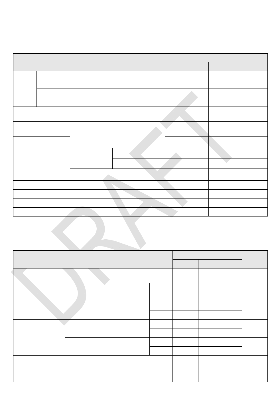
3.8.3 Transmitter Performance Summary
Table 12 Transmitter Performance Summary
Parameter Condition
V
alue Unit
Min Typ Max
Tx
Output
Power
Level
GMSK GSM850, GSM900 Power Step 0 16 18 20 dBm
GSM1800, GSM1900, Power Step 0 19 21 23 dBm
8PSK GSM850, GSM900 Power Step 0 10 12 14 dBm
GSM1800, GSM1900, Power Step 0 13 15 17 dBm
Tx Output Power
Range Static + Dynamic 21 24 27 dB
Tx Output Power
Control Step Size Minimum step size 1 2 3 dB
Adjacent Channel
Power (these break
points are perceived
to be most difficult
to achieve and are
listed for
convenience)
200 kHz offset –30 dBc
400 kHz offset
GMSK –60 dBc
8PSK –56 dBc
1800 kHz offset –70 dBc
RMS phase error GMSK 5 deg
Peak phase error GMSK ± 20 deg
EVM Average% 8PSK 7 %
Origin Offset 8PSK 35 dB
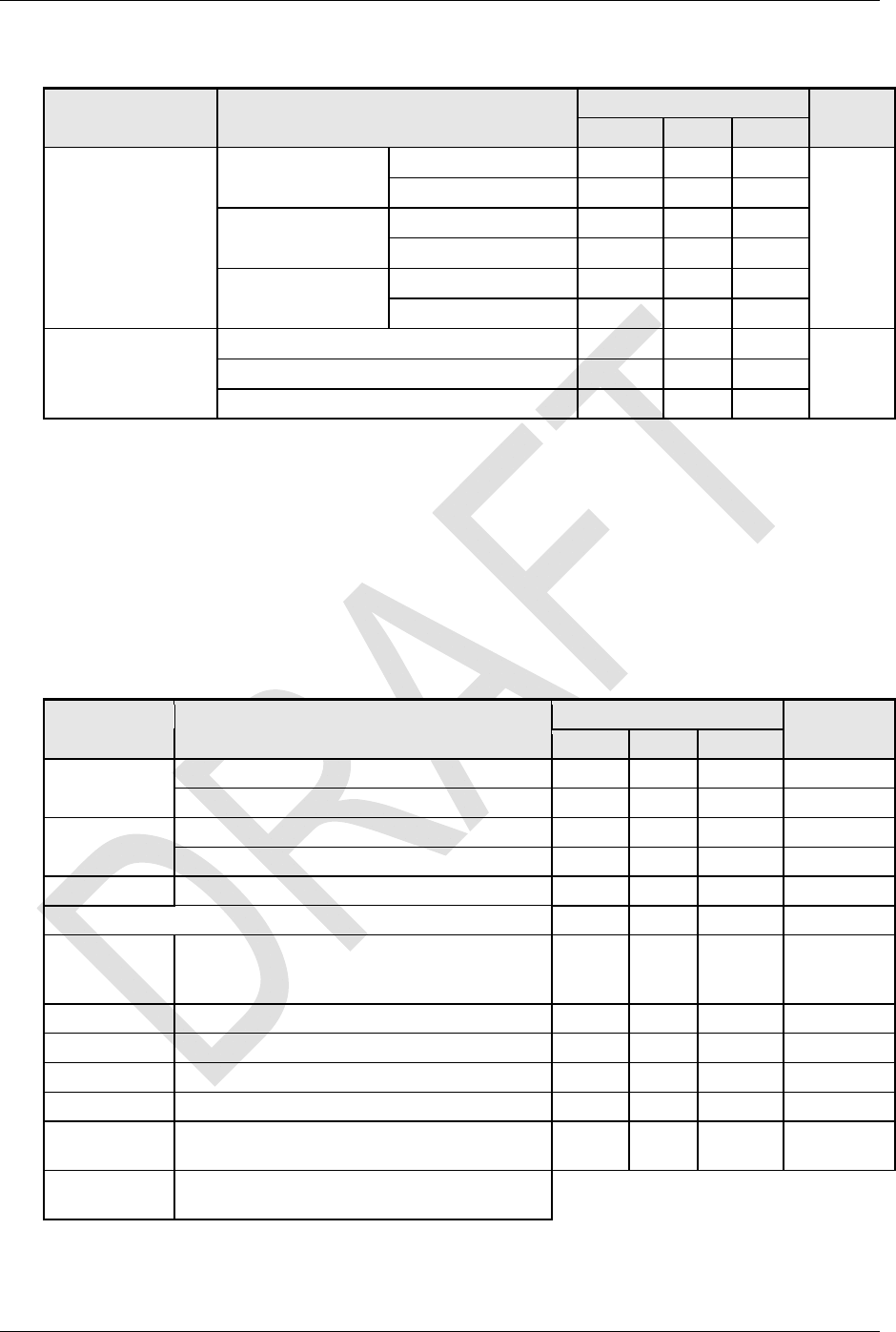
3.8.4 Receiver Performance Summary
Table 13 Receiver Performance Summary
Parameter Condition
V
alue Unit
Min Typ Max
Max Rx Input
Level No damage occurs +10 dBm
Rx Input Level
Static Channel
(Note 1)
SM850, GSM900, BER < 1e-3 GMSK –88 –16 dBm
8PSK –85 –16
GSM1800, GSM1900, BER < 1e-3 GMSK –95 –17 dBm
8PSK –92 –17
Rx Input
Reference
Sensitivity
Fading Channel
(Note 2)
SM850, GSM900, BER < 1e-3 GMSK –85 –16 dBm
8PSK –77.5 –16
GSM1800, GSM1900, BER < 1e-3 GMSK –92 –17 dBm
8PSK –84.5 –17
Intermodulation
Rejection
Interferers 800
kHz, 1600 kHz
offset, Desired 3dB
above sensitivity
GSM850, GSM900 –43
dBm
GSM1800, GSM1900 –49
RadioFrame Networks, Inc. SUPPLIER AND CUSTOMER INFORMATION 17
Specifications S-Series OmniCell@Home Picocell GSM Implementation Guide 998-1027-01 Rev X2
18 CONFIDENTIAL AND PROPRIETARY RadioFrame Networks, Inc.
Parameter Condition
V
alue Unit
Min Typ Max
Out-of-band
blocking
600 kHz offset GSM850, GSM900 –34
dBm
GSM1800, GSM1900 –41
1.6 MHz offset GSM850, GSM900 –26
GSM1800, GSM1900 –31
> 3 MHz offset GSM850, GSM900 –18
GSM1800, GSM1900 –23
In-Band Interferer
0 kHz offset 13
dBc
200 kHz offset –5
400 kHz offset –37
Note1: Static reference sensitivity is measured with TCH/FS and PDTCH/CS-1 for GMSK
and MCS-5 for 8PSK
Note 2: Page 64 of TS 101 087 V8.5.0 lists the fading channel requirements the PicoBTS
must support
3.9 Environmental Specifications
Table 9 represents the environmental specifications for the S-Series system components.
Table 14 Environmental Specifications
Parameter Condition
V
alue Unit
Min Typ Max
Ambient
Temperature
Normal operation 0 27 40 °C
Storage –40 70 °C
Humidity Normal operation relative, non-condensing 0 90 %
Storage, non-condensing 0 90 %
Altitude Relative to mean sea level –60 1800 m
Shock 40 G
Seismic Level 4 earthquake;
meets or exceeds GR-63-CORE Earthquake
Environment NEBS requirements
99.9 % pass
Storage ETSI ETS 300 019-1-1 Class 1.3E
Transport ETSI ETS 300 019-1-2 Class 2.3
Operation ETSI ETS 300 019-1-2 Class 3.1
UL Pollution Degree 3 99.9 % pass
Transport
Vibration NSTA, ISTA compliant 99.9 % pass
RoHS
Directive The PicoBTS will be compliant with the RoHS
Directive
S-Series OmniCell@Home Picocell GSM Implementation Guide Specifications
998-1027-01 Rev X2
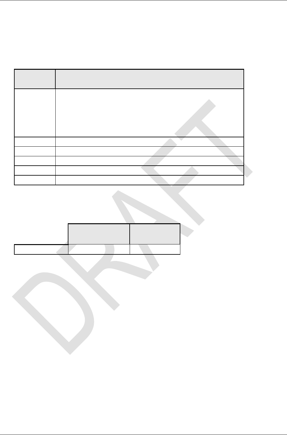
3.10 Safety and Compliance Specifications
The S-Series system will meet the following safety and compliance specifications.
Table 15 Safety and Compliance Specifications <<<PENDING>>>
Parameter Applicable Standard
CE / R&TTE
TS 101 087 V8.5.0
ETSI EN 301 502 V8.1.2 (2001-07) (Requested parts only) – Radio
ETSI EN 301 489-1 V1.5.1 (2004-11) – EMC
ETSI EN 301 489-8 V1.2.1 (2002-08) – EMC
for GSM 900/1800 and 850.1900 Pico Class BTS
ETS 300 019 – Parts met by test or design (TBD)
EN 60950 and IEC 60950
FCC Parts 22 & 24
UL UL60950
IP Rating IP 10 (Intended for indoor use)
RoHS The PicoBTS is designed to meet the RoHS directive
WEEE The PicoBTS is designed to meet the WEEE directive
3.11 Antennas
Table 16 Antennas
Connector Interface
A
ntenna SMA-type Um
Note: With the housing in place, the antennas are not visible.
3.12 Logical Channels
Each PicoBTS supports up to 7 traffic channels (1 GSM/GPRS TRX).
Logical channel configurations:
• BCCH (FCCH + SCH + BCCH + PCH + AGCH)
• Extended BCCH
• Combined BCCH and SDCCH
• SDCCH (SDCCH4 and SDCCH8 configurations)
• TCH (TCH + FACCH + SACCH)
• PDCH
• RACH
RadioFrame Networks, Inc. SUPPLIER AND CUSTOMER INFORMATION 19

Installation S-Series OmniCell@Home Picocell GSM Implementation Guide 998-1027-01 Rev X2
3.13 Services
Voice GSM FR and EFR
AMR TCH_AFS and TCH_AHS
Data GPRS CS 1-2
E-GPRS MCS1-9
E-GPRS Incremental Redundancy
BS20 at up to 9.6 kbps
Encryption A5/1
System Interfaces: Nokia Abis Interface
Network Interfaces: Onboard router that supports
One wide area network port (RJ-45) for connection to
broadband IP backhaul network
Four local area network switch ports (RJ-45) to provide
connectivity for other devices such as WLAN router, PCs, etc.
4 Installation
4.1 Dimensioning Considerations
Dimensioning of infrastructure domain equipment (S-AGW, S-RS, and S-EMS) is covered
in <<<Doc Set To Be Supplied>>>.
4.1.1 CPE Scaling
For the purpose of planning PicoBTS (CPE) deployment, the following assumptions are
valid:
• Each PicoBTS is configured as a BCCH TRX
• Each PicoBTS supports up to 7 FR voice calls (depending on how many slots are
used for GPRS)
• Each S-AGW has the capability of supporting 40 TRXs
4.1.2 Link Dimensioning
Data traffic on links is implementation dependent, but for the purpose of dimensioning
links, the following information is provided.
• Suggested DSL or cable modem bandwidth available at the PicoBTS is 256 kbps
for both uplink and downlink (calculated minimum under “typical” conditions is 182
kbps)
• A complete and successful registration procedure typically results in traffic load
(from PicoBTS to S-RS) of 14 IP/TCP/SSL packets, for a total of about 1733 bytes
and (from S-RS to PicoBTS) of 12 IP/TCP/SSL packets, for a total of about 2226
bytes. Therefore, the total for both directions is 26 packets, or approximately 4000
bytes.
Note: The S-RS employs a throttling mechanism such that a limited number of registration requests
may be handled concurrently. Each request spawns a temporary thread in the S-RS process,
20 CONFIDENTIAL AND PROPRIETARY RadioFrame Networks, Inc.

S-Series OmniCell@Home Picocell GSM Implementation Guide Installation
998-1027-01 Rev X2
• The bandwidth required for a fully loaded S-AGW at the S-AGW – IP backhaul
interface is about 200 kbps (per TRX) * 40 = 8 Mbps
4.2 Preparation for Installation
In Section 4.3 you will connect the cabling and bring up the PicoBTS CPE. Installation
requires no training or prior expertise on the product. The software architecture of the S-
Series allows for a “plug-and-play” behaviour. No intervention is required if the
preparation described in this section has been accomplished.
Before the PicoBTS CPE is able to register, it must be provisioned with the FQDN (or IP
address) of the S-RS in order to initiate the process. (For security, the S-RS does not
advertise or poll.) Normally this provisioning is pre-loaded in the CPE.
Refer to Appendix B, Default Configuration of the OmniCell@Home Picocell as Shipped,
for the Factory settings for the PicoBTS.
4.3 Installing CPE Equipment
Note: Infrastructure equipment must be operational before CPE can be installed.
The PicoBTS hardware is installed at customer premise locations, most likely
at different times and by different personnel.
The following items come with the PicoBTS:
• Power supply transformer assembly with country-specific adapters
• Ethernet cable: CAT5e, 7 ft (2.13 m)
The customer needs to supply additional Ethernet cables if additional equipment will be
connected to the PicoBTS router on the LAN side. Auto MDX/MDIX is supported.
The PicoBTS should be placed on a table top in the vertical position as shown in Figure
1.
Plan to route the necessary cabling to the location of the PicoBTS, including power, WAN
cable, and any LAN cables.
4.3.1 Mechanical Installation Time
Mechanical installation time for the PicoBTS is designed to be minimal, and should be
less than 10 minutes.
Connect the PicoBTS WAN port to the broadband IP backhaul network (xDSL or cable
modem).
Connect the LAN ports to the local area network as necessary.
RadioFrame Networks, Inc. SUPPLIER AND CUSTOMER INFORMATION 21
Installation S-Series OmniCell@Home Picocell GSM Implementation Guide 998-1027-01 Rev X2
4.3.2 Bringing up the PicoBTS
Connect the provided AC power cable to the PicoBTS, and, using the correct adapter for
the country’s power receptacles, plug the cable into the wall receptacle. Within three
minutes, the PicoBTS registers and is ready for use.
CPE IP Address
PicoBTSs can be configured with a static IP address, or addresses can be assigned by
DHCP. To change settings on a PicoBTS, you can connect a PC to one of the LAN ports
on the PicoBTS and browse to 192.168.0.1.
The default username is admin, with password admin123
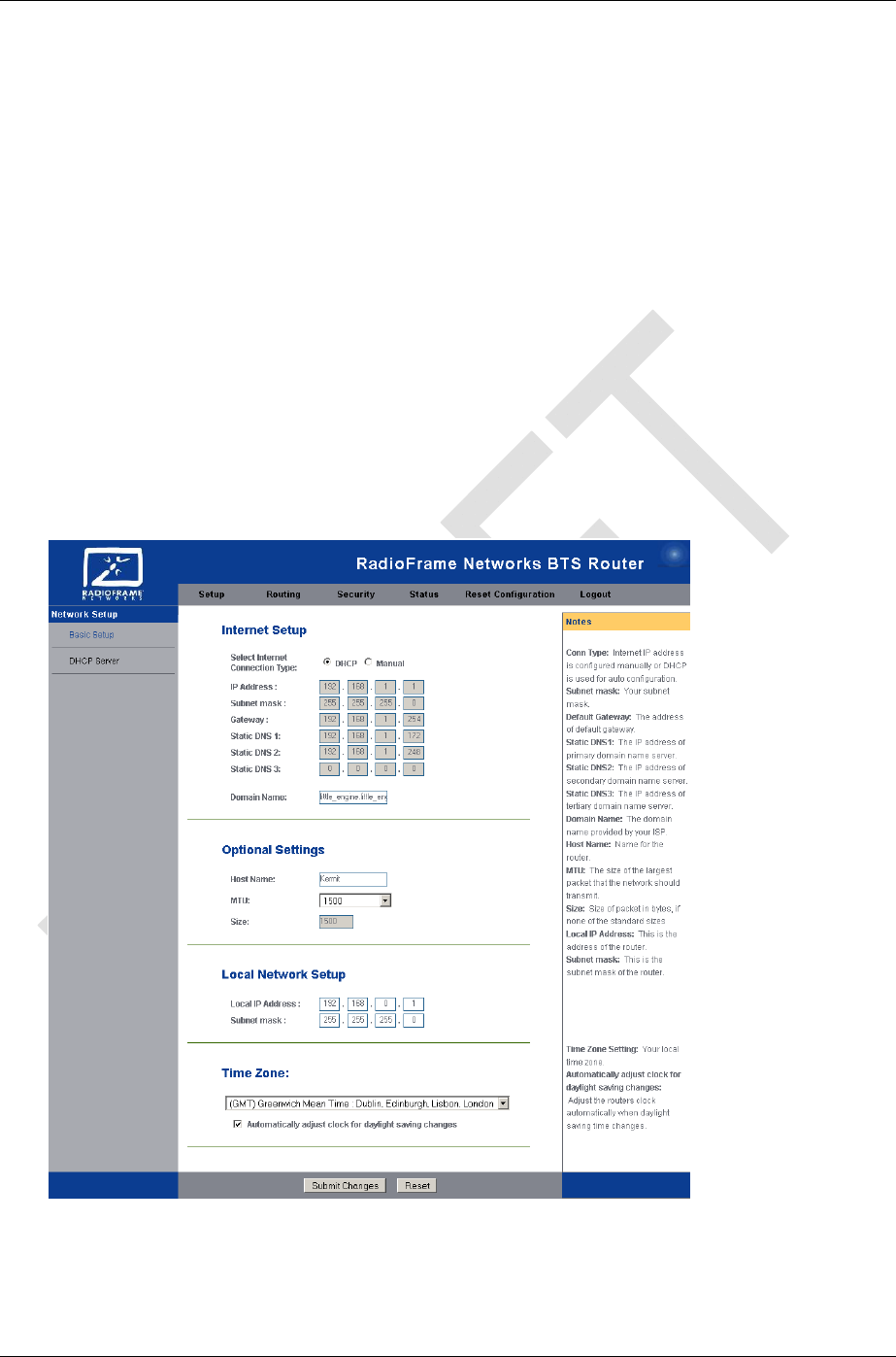
Refer to Figure 4. On the general setup page you can select either DHCP or static IP
address.
It is not critical what IP addresses the PicoBTSs receive as long as they do not clash with
anything else on the same network.
Figure 4 PicoBTS Router Configuration Page
22 CONFIDENTIAL AND PROPRIETARY RadioFrame Networks, Inc.

S-Series OmniCell@Home Picocell GSM Implementation Guide Scheduled and Unscheduled Maintenance
998-1027-01 Rev X2
5 Scheduled and Unscheduled Maintenance
5.1 Maintenance
5.1.1 Customer Domain Component (PicoBTS)
There are no maintenance procedures required for the PicoBTS.
5.2 Troubleshooting Guidelines
Technicians should conduct the following troubleshooting steps in order:
1 Visually inspect for fault indication (LEDs).
2 Inspect the Alarm Manager, and follow alarm resolution procedures.
3 Refer to section1.4, “Repair and Technical Support” on page 8.
4 Complete and save the serial log upload of <<<TBS>>>.
5 Refer to sections <<<power down procedure TBS>>> and <<<FRU procedures:
TBS>>>.
5.2.1 Fault Indications
<<<TO BE SUPPLIED>>>
5.2.2 System Manager Alarms
<<<TO BE SUPPLIED>>>
5.2.3 Serial Log Upload Procedure
<<<TO BE SUPPLIED>>>
5.2.4 Power Down Procedure
<<<TO BE SUPPLIED>>>
5.2.5 Field Replaceable Unit (FRU) Procedures
<<<TO BE SUPPLIED>>>
6 System Configuration Changes
The S-Series system is shipped with the latest software installed. With each new software
release, RadioFrame Networks provides its customers with the new software and
accompanying information in the RadioFrame Networks Customer Release Notes.
Software Download to the PicoBTSs is accomplished remotely from the Software
Download Server.
System Manager contains two separate partitions in which to install software: active and
inactive. This provides the means to revert back to a previous version of system software
if required.
RadioFrame Networks, Inc. SUPPLIER AND CUSTOMER INFORMATION 23

System Configuration ChangesS-Series OmniCell@Home Picocell GSM Implementation Guide998-1027-01 Rev X2
6.1 Adding S-Series Components
<<<PROCEDURE TO BE SUPPLIED>>>
6.2 Spares, Parts and Suppliers
<<<TO BE SUPPLIED>>>
24 CONFIDENTIAL AND PROPRIETARY RadioFrame Networks, Inc.

S-Series OmniCell@Home Picocell GSM Implementation Guide System Configuration Changes
998-1027-01 Rev X2
Appendix A. Definitions and Abbreviations
Term Definition
A-bis Interface between BTS and BSC
A/D Analog to Digital
AGW Aggregating Gateway (proposed function of IP BSC)
AP Access Point
ARFCN Absolute Radio Frequency Channel Number
ARP Address Resolution Protocol
BGP Border Gateway Protocol
BSS Base Station System
BTS Base Transceiver Station
CLI Command Line Interface
CN Core Network
DAC Digital-to-Analog Converter
DES Digital Encryption Standard
DHCP Dynamic Host Control Protocol
DSP Digital Signal Processing
EML Element Management Layer
EMS Element Management System
FCAPS Fault, Configuration, Accounting, Performance and
Security
FIT Failure in Time
FPGA Field Programmable Gate Array
FQDN Fully Qualified Domain Name
FRU Field Replaceable Unit
GPRS General Packet Radio Service
HDLC High-Level Data Link Control
HLR Home Location Register
HO Handover
HRBS Home Radio Base Station
HSDPA High-Speed Downlink Packet Access
HSS Home Subscriber Server
IGRP Interior Gateway Routing Protocol
LA Location Area
LME Local Management Entity
LMT Local Maintenance Terminal
LSA Localized Service Area
LSAID Localized Service Area Identity
MAC Media Access Control
MCC Mobile Country Code
RadioFrame Networks, Inc. SUPPLIER AND CUSTOMER INFORMATION 25

System Configuration ChangesS-Series OmniCell@Home Picocell GSM Implementation Guide998-1027-01 Rev X2
26 CONFIDENTIAL AND PROPRIETARY RadioFrame Networks, Inc.
Term Definition
MIB Management Information Base
MNC Mobile Network Code
MO Managed Object
MS Mobile Station
NB neighbor cell (list)
NE Network Element
NEL Network Element Layer
O&M Operations and Maintenance
OAM Operations, Administration, Maintenance
OMC Operations and Maintenance Center
OSPF Open Shortest Path First
OTAP Over the Air Programming
PCU Packet Control Unit
PHY Physical Layer
PLL Phase Lock Loop
PLMN Public Land Mobile Network
RBS Radio Base Station
RFN RadioFrame Networks
RIP Routing Information Protocol
RS Registration Server (proposed function of IP BSC)
RSSI Received Signal Strength Indication
RSZI Regional Subscription Zone Identity
RTP Real-time Transport Protocol
SGSN Serving GPRS Support Node
SIM Subscriber Identity Module
SME Small to Medium Enterprise
SMI Structure of Management Information
SMLC Serving Mobile Location Center
SNMP Simple Network Management Protocol
SRTP Secure Real-time Transport Protocol
STK SIM Card Toolkit
TMN Telecommunications Management Network
TMSI Temporary Mobile Subscriber Identity
TRAU Transcoder Rate Adaptation Unit
TRX Transmit/Receive Pair
UART Universal Asynchronous Receiver/Transmitter
VLR Visitor Location Register
ZC Zone Code

S-Series OmniCell@Home Picocell GSM Implementation Guide System Configuration Changes
998-1027-01 Rev X2
Appendix B. Default Configuration of the
OmniCell@Home Picocell as Shipped
Setting Default
Router Information
Current Time —
Mac Address —
Domain Name —
Host Name —
Internet Information
Connection Type (WAN Port) DHCP
IP Address 192.168.1.1
Subnet Mask 255.255.255.0
Default Gateway 192.168.1.254
DNS1, -2, -3 —
MTU —
Local Network Information
Local IP 192.168.0.1
Subnet Mask 255.255.255.0
Dynamic Routing Disabled
DHCP Details
DHCP Server Enabled
Security Information
HTTPS Disabled
RadioFrame Networks, Inc. SUPPLIER AND CUSTOMER INFORMATION 27
System Configuration ChangesS-Series OmniCell@Home Picocell GSM Implementation Guide998-1027-01 Rev X2
Appendix C. RF Emissions Precautions
C.1 Exposure vs. Frequency
Overall exposure may be affected by radio frequency generating facilities that exist at the
time the equipment is being installed or even by equipment installed later. Therefore, the
effects of any such facilities must be considered in site selection and in determining
whether a particular installation meets the requirements of safe operation. Determining
the compliance of transmitter sites of various complexities may be accomplished by
means of computational methods. For more complex sites, direct measurement of power
density may be more expedient. Persons responsible for installation of this equipment are
urged to consult the listed reference material to assist in determining whether a given
installation complies with the applicable limits. In general the following guidelines should
be observed when working in or around radio transmitter sites:
Warning!
All personnel should have electromagnetic energy awareness training.
Warning!
Obey all posted signs.
Warning!
Assume all antennas are active.
Warning!
Never operate transmitters without shields during normal operation.
Warning!
Do not operate base station antennas in equipment rooms.
28 CONFIDENTIAL AND PROPRIETARY RadioFrame Networks, Inc.

S-Series OmniCell@Home Picocell GSM Implementation Guide System Configuration Changes
998-1027-01 Rev X2
RadioFrame Networks, Inc. SUPPLIER AND CUSTOMER INFORMATION 29
Appendix D. Communication Interconnects
<<<TO BE SUPPLIED>>>