Radwin RW2058 Outdoor radio unit operating in 5.8GHz band User Manual STW
Radwin Ltd. Outdoor radio unit operating in 5.8GHz band STW
Radwin >
Contents
- 1. User Manual
- 2. Manual Part 1
- 3. Manual
User Manual

RADWIN 1000/2000 User Manual Version 2.12 2-1
Chapter 2
Site Preparation
Planning the Link Site
Overview
Link site planning consists of a set of surveys, which must be carried out
before any equipment is brought to the site. If for some reason, the out-
come of any of these surveys is negative, site re-location will need to be
considered.
A Site Survey consists of three stages:
1. Preliminary survey - The proposed link is analyzed in the office using a
topographic map.
2. Physical survey - The locations of the RADWIN 1000/2000 indoor and
outdoor equipment are determined on-site.
3. Radio Frequency (RF) survey - It is recommended that the installation
area be scanned with a spectrum analyzer, to identify RF interference so
as to determine a clear channel for RADWIN 1000/2000 installation (on-
site).
The Site Survey
Introduction
RADWIN 1000/2000 wireless links must be planned before installation. The
designated installation site must be appraised to determine that the wire-
less system is able to operate efficiently and provide connectivity without
signal degradation.
RADWIN 1000/2000 offers a wide operating frequency range. A free fre-
quency channel must be determined within the operating range, for opti-
mum performance.
Recommended Equipment
Stage 1: Preliminary Survey
• Topological map of the area

Stage 1: Preliminary Survey Chapter 2
RADWIN 1000/2000 User Manual Version 2.12 2-2
• Urban map of the area
•Compass
Stage 2: Physical Survey
• 100 meter tape measure
• Ohmmeter, to check ground connection
•Binoculars
•Map
• Digital camera
• Paper, pencil, and a clipboard
• GPS device (optional)
• Compass (optional)
Stage 3: RF Survey
• Spectrum Analyzer with Max Hold function and screen capture facil-
ity that can store multiple images, for documentation purposes
• RF accessories (connectors and cables)
• Communication devices (for example, cellular phones, or a set of
walkie-talkies)
Stage 1: Preliminary Survey
A preliminary survey is necessary before visiting potential installation sites.
As much detail as possible should be obtained about the two designated
ODU installation sites and the area between them.
¾To perform a preliminary survey:
1. Mark the two designated installation sites on a topographic map of the
area.
2. Measure the distance between the sites; check that it is within the speci-
fied range of the RADWIN 1000/2000.
3. On the urban map, check for developed areas situated between the two
installation sites. Pay attention to these areas when performing the phys-
ical site survey; there may be tall buildings, RF towers, or transmitters,
which could cause interference to the link.
4. Check the area between the two sites for obstructions such as:
• High ground - hills or mountains
• Lakes or large bodies of water. Water has a reflection effect on RF
signals like a building. This type of reflection causes the received
amplitude to be reduced. As a rule of thumb, the presence of a large
body of water between the link sites may double the required
antenna height.
5. Determine and record the compass bearings between both ODUs, rela-
tive to north.
6. If there are obstructions between the two sites, calculate the Fresnel
Zone (see appendix D for details).

Stage 2: Physical Survey Chapter 2
RADWIN 1000/2000 User Manual Version 2.12 2-3
7. If the site chosen does not meet requirements, consider alternative sites.
8. Use the Link Budget Calculator (on the CD supplied with the RADWIN
1000/2000 or using the RADWIN Manager) to determine the expected
performance.
Stage 2: Physical Survey
The physical site survey reviews the environment of the proposed RADWIN
1000/2000 installation location, to ensure that the link sites are suitable for
the wireless network. The results of the physical site survey should be
recorded.
¾To perform a physical survey:
1. From the compass readings taken in the preliminary survey, find the azi-
muth (horizontal position) that the ODU should face towards the second
ODU.
2. Using binoculars, locate any obstructions such as tall trees, high build-
ings, hills or mountains. Look for other RF towers between the two sites.
Mark the locations of the obstructions on the map.
3. Determine the location for the ODU (having regard for existing rooftop
installations and tower space). It should be above any obstructions, con-
sidering the Fresnel zone (see appendix D).
4. If you need to install the ODU on a tower, make sure that the tower is far
away from overhead electric power lines.
5. Determine a location for the indoor equipment; it should be as close as
possible to the ODU. At an existing site, there is probably an equipment
room with cable-routing channels.
6. Measure and record the path length of the cable from the ODU position
to the indoor equipment room.
7. Determine the ground and lightning connection points of the installation.
The RADWIN 1000/2000 ODU and IDU must both be grounded.
8. Using the Ohmmeter, measure and record the resistance of the required
installation to the grounding point. The resistance must be less than 1O
ohm.
Note
It is advisable to go on a clear day, so you can more easily see any
obstructions between the two sites.
Note
The IDU - ODU cable length limit is 100m, in accordance with IEEE 10/
100BaseT standards.

Additional Outdoor Site Requirements Chapter 2
RADWIN 1000/2000 User Manual Version 2.12 2-4
9. Review the results of the physical site survey. Decide if the site is suitable
for the RADWIN 1000/2000 wireless network installation.
• If the site is suitable, continue with stage 3, the RF survey
• If the site is not suitable, survey another site
Additional Outdoor Site Requirements
The ambient outdoor operating temperature should be -35 to 60°C (-31 to
140°F).
Additional Indoor Site Requirements
The following requirements guarantee proper operation of the system:
• For IDU-C units, allow at least 90 cm (36 “) of front clearance for
operating and maintenance accessibility. Allow at least 10 cm (4 “)
clearance at the rear of the unit for signal lines and interface cables
• The ambient operating temperature should be 0 to 50°C (32 to 122
°F) at a humidity of up to 90%, non condensing
Stage 3: RF Survey
The RF survey examines the wireless environment of the RADWIN 1000/
2000 installation site, to determine whether there are available channels
within the RADWIN 1000/2000 operating frequency band. An RF survey is
performed using a spectrum analyzer.
It is advisable to familiarize yourself with the spectrum analyzer before
going out on site, specifically the Max Hold and Marker functions.
You should perform the RF survey at both proposed link sites.
The survey should be carried out during a busy time of day, to best judge
the worst-case radio interference. Allow 2-4 hours duration for a good RF
survey.
Note
It is possible to install the RADWIN 1000/2000 link and use the RADWIN
Manager to find a clear channel. Each frequency channel can be evaluated
in turn. Achievement of a clear channel is indicated by the Quality bar on
the Channel Setting window (see figure 4-13) becoming green.

RADWIN 1000/2000 User Manual Version 2.12 3-1
Chapter 3
Hardware Installation
This chapter sets out the requirements and procedures for the hardware
installation and alignment of a RADWIN 1000/2000 link in accordance with
the prior planning as set out in chapter 2. It is intended to guide qualified
field technicians.
Safety Practices
Preventing overexposure to RF energy
To protect against overexposure to RF energy, install the ODUs so as to pro-
vide and maintain minimal separation distances from all persons.
When the system is operational, avoid standing directly in front of the
antenna. Strong RF fields are present when the transmitter is on. The ODU
must not be deployed in a location where it is possible for people to stand
or walk inadvertently in front of the antenna.
Grounding
All RADWIN products should be grounded during operation. In addition:
•The ODU should be earthed by a wire with diameter of at least
12AWG.
The RADWIN 1000/2000 ODU must be properly grounded to protect
against lightning. It is the user's responsibility to install the equip-
ment in accordance with Section 810 of the National Electric Code,
ANSI/NFPA No.70-1984 or Section 54 of the Canadian Electrical
Code. These codes describe correct installation procedures for
grounding the outdoor unit, mast, lead-in wire and discharge unit. It
Warning
Outdoor units and antennas should be installed ONLY by experienced
installation professionals who are familiar with local building and safety
codes and, wherever applicable, are licensed by the appropriate
government regulatory authorities. Failure to do so may expose the end
user or the service provider to legal and financial liabilities. RADWIN and its
resellers or distributors are not liable for injury, damage or violation of
regulations associated with the installation of outdoor units or antennas.

Protection against Lightning Chapter 3
RADWIN 1000/2000 User Manual Version 2.12 3-2
also lays down the size of grounding conductors and connection
requirements for grounding electrodes.
The RADWIN 1000/2000 ODU must be grounded to a Protective
Earth as described in appendix E and in accordance with the Local
Electrical Regulations.
• The earth lug on the IDU-C should be connected to the protective
earth at all times, by a wire with a diameter of 18 AWG or wider.
Rack-mounted equipment should be mounted only in earthed racks
and cabinets.
Further, you should -
• Always make the ground connection first and disconnect it last
• Never connect telecommunication cables to ungrounded equipment
• Ensure that all other cables are disconnected before disconnecting
the ground
More detailed guidelines are supplied in appendix E.
Protection against Lightning
The use of lightning protection is dependent on regulatory and end user
requirements. All of RADWIN outdoor units are designed with surge limiting
circuits to minimize the risk of damage due to lightning strikes. RADWIN
recommends the use of additional surge arrestor devices to protect the
equipment from nearby lightning strikes.
See appendix E for detailed installation instructions of lightning protection
devices.
General
• It is recommended that installation of the outdoor unit be contracted
to a professional installer.
• Before working on equipment connected to power lines or telecom-
munication lines, you should remove jewelry or any other metallic
object that may come into contact with energized parts.
• Use extreme care when installing antennas near power lines.
• Use extreme care when working at heights.
• When using an AC power source for RADWIN 1000/2000 always use
the AC power adapter supplied by RADWIN.
• Use the right tools. In addition to standard tools required for any
kind of ODU or antenna installation, RADWIN 1000/2000 requires
additional specific tools detailed on page 3-5 below.
Package Contents
The RADWIN 1000/2000 packages include the following items:
ODU Package Contents
The ODU package contains:
ODU Package Contents Chapter 3
RADWIN 1000/2000 User Manual Version 2.12 3-3
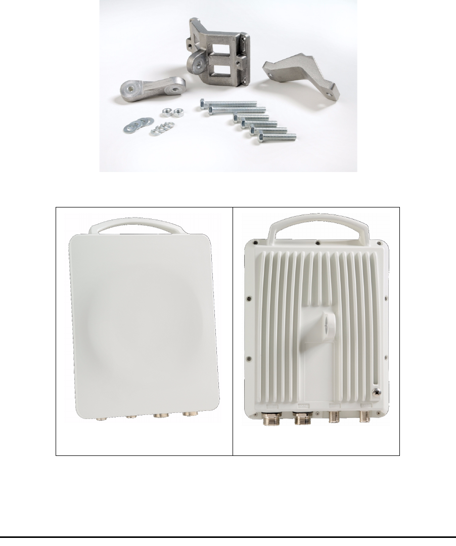
• One ODU - see figure 3-2 below for front and rear view
• An ODU mounting kit - see figure 3-1 below
• A CD containing -
• the RADWIN Manager
•Quick Start Guide
• User Manual
• Link Budget Calculator
• Label showing the MAC address and the alternative Community
string. The label is self-adhesive. You should keep this label safe
• Cable glands (to be used with the ODU-IDU cable)
Figure 3-1: ODU Mounting kit
Figure 3-2: Connectorized ODU - Front and rear views
ODU - Front View ODU - Rear View
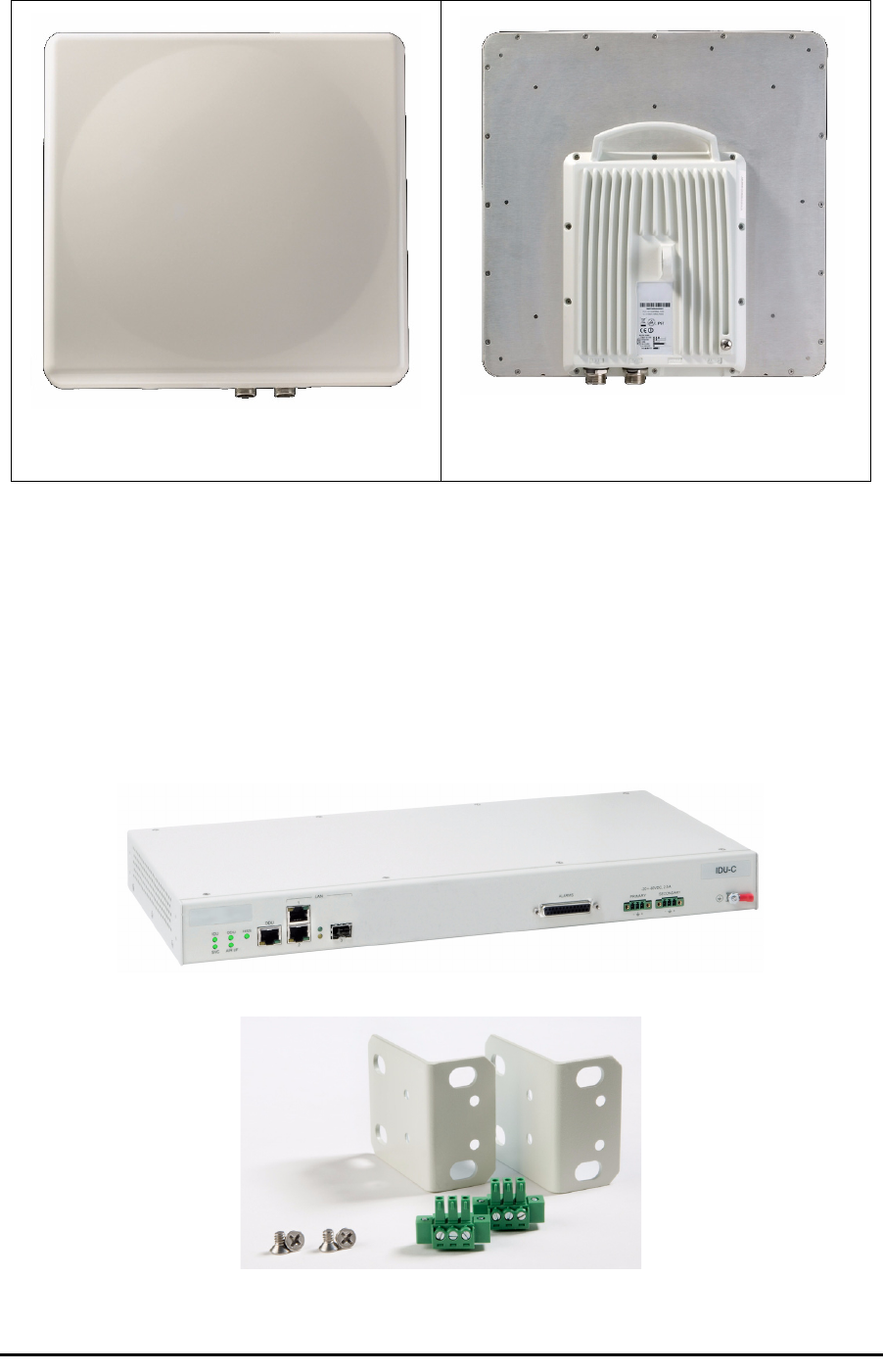
IDU Package Contents Chapter 3
RADWIN 1000/2000 User Manual Version 2.12 3-4
Figure 3-3: Integrated ODU - Front and rear views
IDU Package Contents
The IDU package contains:
• IDU-C - see figure 3-4 below.
• 19” rack mounting kit - see figure 3-5 below
• Two DC power plugs for power cables - see figure 3-5 below
Figure 3-4: IDU-C Package contents - the IDU-C
Figure 3-5: IDU-C Package contents - the mounting kit and DC power plugs
ODU - Front View ODU - Rear View

External Antenna Package Contents Chapter 3
RADWIN 1000/2000 User Manual Version 2.12 3-5
External Antenna Package Contents
•Antenna
• RF cable 1m (3’) long; two cables supplied with bipolar antennas,
single cable supplied with monopolar antennas
• Mounting kit
Additional Tools and Materials Required
The following is a list of the equipment and materials required to install
RADWIN 1000/2000 hardware.
Tools and Materials
• Crimping tool for RJ-45 (if the ODU-IDU cable is without connectors)
• Spanner/wrench 13 mm (½”)
• Drill (for wall mounting only)
•Cable ties
• Sealing material
Cables and connectors
• ODU grounding cable 12AWG
• IDU grounding cable 18AWG
• ODU-IDU cable (outdoor class, CAT-5e, 4 twisted pairs, 24AWG)
Hardware Installation Sequence
The following steps are required to install the RADWIN 1000/2000 system:
1. Mounting the ODUs, page page 3-6.
2. Mounting the external antennas (if used), page page 3-7.
3. Mounting the Lightning Protection devices (if used), page page 3-7.
4. Outdoor connections, page page 3-8.
5. Mounting the IDUs, page page 3-8.
6. Indoor connections, page page 3-11.
7. Aligning the ODUs/antennas, page page 3-12.
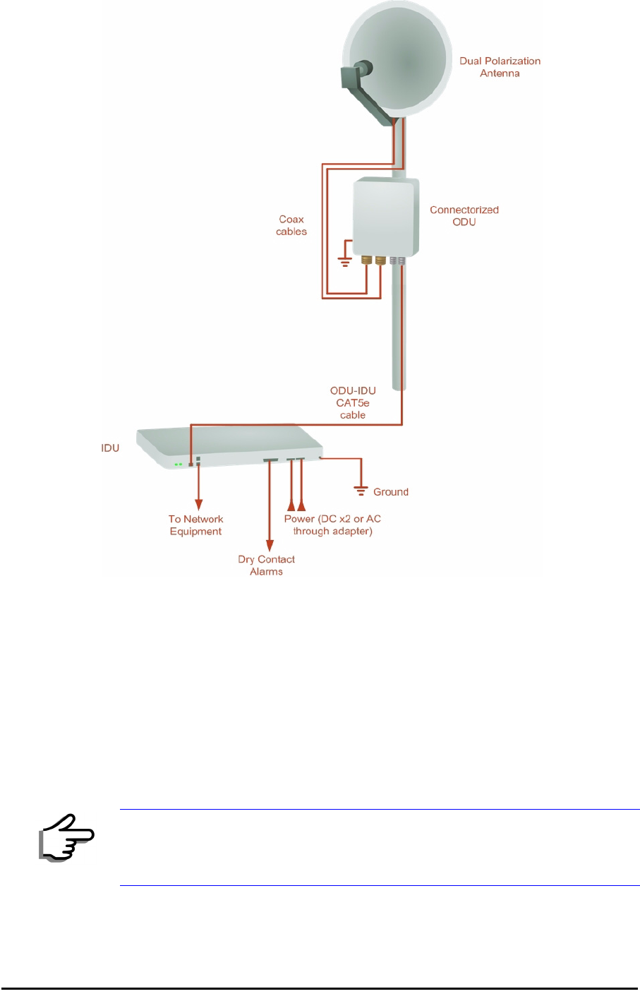
See figure 3-6 below, which illustrates a typical installation of RADWIN
1000/2000 with an external antenna.
Outdoor installation Chapter 3
RADWIN 1000/2000 User Manual Version 2.12 3-6
Figure 3-6: Typical Installation Diagram (with external antenna)
The installation steps are detailed in the following sections.
Outdoor installation
Mounting the ODU
The ODU can be mounted on a pole or a wall. In both installations, the sup-
plied mounting kit is used to secure the ODU.
A RADWIN 1000/2000 link operates in pairs of two ODUs with the same
configuration. Both ODUs must be installed, and the antennas aligned for
maximum throughput.
Note
A mast-sited ODU typically uses a pole attached to the mast.
Mounting external antennas Chapter 3
RADWIN 1000/2000 User Manual Version 2.12 3-7
¾To mount the ODU on a pole or a wall:
1. Ensure that the ODU is properly grounded.
2. Mount the ODU onto the pole or wall. Ensure that the unit is oriented so
that the cable connectors are at the bottom. (If they are on top,
water may penetrate into the unit causing damage.)
3. Refer to Appendix C, Pole and Wall Installation for detailed ODU
mounting kit contents and schematics.
Mounting external antennas
If you are using ODU with an integrated antenna, skip to Mounting the
Lightning Protection Devices below.
The supplied mounting kit is used to mount the antenna onto a pole. The
antennas must be aligned for maximum throughput.
¾To mount an external antenna:
1. To mount an external antenna ensure that the antenna is properly
grounded and then mount the antenna onto the pole. Refer to Appen-
dix C, Pole and Wall Installation for detailed antenna mounting
instructions.
2. Follow the mounting instructions supplied with the antenna.
Mounting the Lightning Protection Devices
The use of lightning protection is dependent on regulatory and end user
requirements. The RADWIN 1000/2000 ODU is designed with surge limiting
circuits to minimize the risk of damage due to lightning strikes. RADWIN
Warning
Prior to connecting cables to the ODU, the protective earth terminal (screw)
of the ODU must be connected to an external protective ground conductor
or to a grounded pole.
• Only a qualified person using the proper safety equipment should
climb the antenna mast
• Only qualified professional personnel should install or dismantle
ODUs and masts
Note
Do not tighten the ODU to its mounting brackets until the alignment
process of the antenna is complete.
Ensure that there are no direct obstructions in front of the ODU or
interference from man-made obstacles.
Warning
Do not stand in front of a live antenna.
Outdoor Connections Chapter 3
RADWIN 1000/2000 User Manual Version 2.12 3-8
recommends the use of additional surge arrestor devices to protect the
equipment from nearby lightning strikes.
Refer to appendix E for detailed installation instructions of lightning protec-
tion devices.
Outdoor Connections
¾To complete the outdoor connections:
1. Connect the ground cable to the ODU chassis as marked on the ODU.
2. Connect the antenna cable(s) to the ODU.
3. Connect the lightning protection device to the ODU (see appendix E).
4. Attach the ODU-IDU cable to the ODU RJ-45 connector (see appendix B
for the connector pin-out)
5. Screw in the cable glands to ensure hermetic sealing of the ODU.
6. Secure the cables to the pole, mast or brackets using UV-rated cable ties.
Indoor Installation
Mounting the IDUs
The RADWIN 1000/2000 IDUs are all rack mounted, as shown in figure 1-
6. A front panel keyed schematic of a rack mounted IDU-C is shown in
figure 3-7 below.
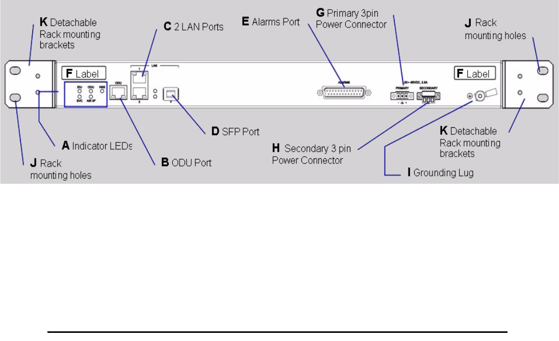
Figure 3-7: IDU-C front panel
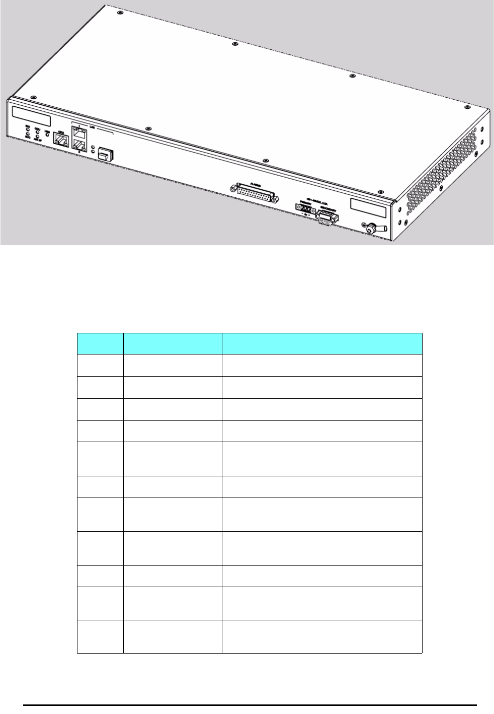
In figure 3-8 we display a perspective view of the IDU-C:
Mounting the IDUs Chapter 3
RADWIN 1000/2000 User Manual Version 2.12 3-9
Figure 3-8: IDU-C - A perspective view
Further description of the keyed items in figure 3-7 is shown in table 3-1
below:
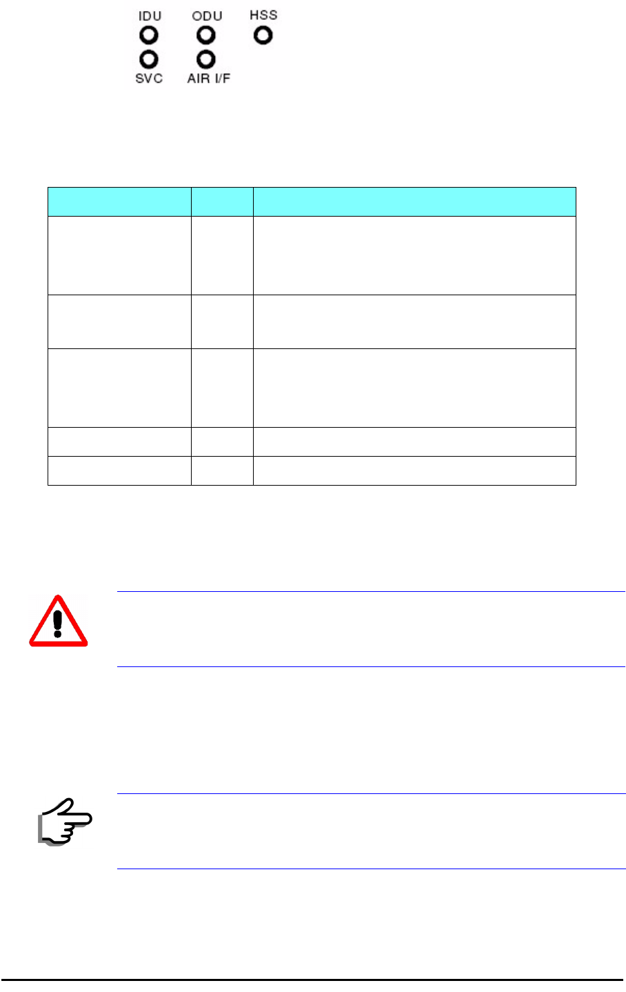
The Indicator LEDs (Item A in table 3-1 above) are shown in more detail in
figure 3-9 below:
Table 3-1: Components of an IDU-C front panel
Key Label Remarks
A Indicator LEDs See figure 3-9.
BODU Port RJ-45 connector, see table B-1.
C2 LAN Ports Ethernet, RJ-45 connector, see table B-2
D SFP Port The IDU-C is SFP ready.
E Alarm Ports Standard DB25 female connector, see
table B-3.
F Label indent Place for adhesive identification labels
G Primary 3 pin Power
Connector Standard 3 pins in line power connector,
see table B-4.
H Secondary 3 pin
Power Connector Standard 3 pins in line power connector,
see table B-4.
I Grounding Lug Use the lug supplied
JRack mounting
holes
KDetachable Rack
mounting brackets
Mounting the IDUs Chapter 3
RADWIN 1000/2000 User Manual Version 2.12 3-10
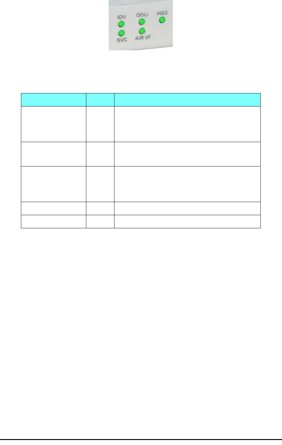
Figure 3-9: IDU-C LEDs
The purpose of the LEDs is shown in table 3-2 below:
¾To mount an IDU (using figure 3-7 above):
1. If the rack already holds other equipment, ensure that it is properly
grounded.
2. Attach the rack mounting brackets (K) to the IDU.
3. Bolt the IDU into an empty slot in the rack, ensuring that it sits securely.
4. Ground the IDU to the rack using grounding lug I. The IDU should be left
permanently grounded.
Table 3-2: IDU-C Front Panel LEDs
Name Color Function
IDU Green
Green
Red
IDU operational
During power-up only
Failure
ODU Green
Red
ODU-to-IDU communication link is operating
ODU-to-IDU communication link is disrupted
AIR I/F Green
Orange
Red
Wireless link is synchronized
During installation mode only
Wireless link lost synchronization
SVC Off
HSS Off
Warning
Do not proceed with installation into a “live” rack unless it is properly
grounded.
Note
Instead of using the rack mounting brackets, the IDU may be rail mounted
using the four screw holes on each of its sides.

Connecting power to the IDU Chapter 3
RADWIN 1000/2000 User Manual Version 2.12 3-11
Connecting power to the IDU
The IDU-C has redundant power connection circuits (items G and H in
figure 3-7 above). An enlarged schematic of the power connectors is
shown in below:
Figure 3-10: DU-C ower connectors
The connectors are 3 pin in line female, with polarities (left to right) minus,
ground, plus. To avoid damage to the IDU, always use an AC/DC adapter
supplied by RADWIN.
Ensure that the IDUs at both sites are powered up.
Connecting the ODU to the IDU
The ODU-IDU cable conducts all the user traffic between the IDU and the
ODU, and also provides power to the ODU. The maximum length of the
ODU-IDU cable is 100m (328 ') in accordance with 10/100BaseT standards.
The ODU-IDU cable is supplied pre-assembled with RJ-45 connectors, at the
length specified when ordering, or as a cable drum with spare connectors. If
the ODU-IDU cable was not ordered, use an outdoor class, CAT-5e 24AWG
shielded cable. See appendix B for Wiring Specifications.
To connect the ODU to the IDU, route the cable from the ODU to the IDU,
secure the cable along its path and connect the cable to the ODU RJ-45
connector on the IDU (see item B in figure 3-7 above).
Installing a Link using PoE Devices
The PoE device is a very simple unit having a power input connector and
two Ethernet ports. It is AC powered, and has a power LED.
¾To prepare a link using PoE devices:
1. To connect the ODU to the PoE device, route the cable from the ODU to
the PoE device, secure the cable along its path and connect the cable to
the P-LAN-OUT RJ-45 connector on the PoE device.
2. Connect it to AC power.
3. Repeat steps 1 to 2 for the second link.

Connecting User Equipment Chapter 3
RADWIN 1000/2000 User Manual Version 2.12 3-12
Connecting User Equipment
¾To connect user equipment to the IDU:
• Connect user switch/router or any other compatible device to the IDU
panel RJ-45 ports designated LAN (see item C in figure 3-7 above).
Refer to appendix B, Wiring Specifications, for connector pinouts.
¾To connect user equipment to the PoE device:
• Connect a user switch, router or any other compatible device to the PoE
device RJ-45 port designated LAN-IN. Refer to appendix B, Wiring
Specifications, for connector pinouts.
Connecting and Aligning ODUs / Antennas
You perform antenna alignment using the ODU's audible tone.
To speed up the installation time, alignment of a RADWIN 1000/2000 sys-
tem should be performed by two teams simultaneously, at site A and at site
B.
¾To align ODUs with integrated antennas or external bipolar antennas:
1. For external bipolar antennas: Using a coax cable with N-Type connec-
tors, connect the vertical polarization connector of the antenna to the
ANT 1 connector of the ODU.
2. For external bipolar antennas: Using a coax cable with N-Type connec-
tors, connect the horizontal polarization connector of the antenna to the
ANT 2 connector of the ODU.
3. Ensure that power is connected to the IDUs at both sites.
4. Ensure normal operation of the IDUs by the LED indications on the front
panel.
Provided that site A detects the signal from site B, the ODU starts beep-
ing 20 seconds after power up, and continues beeping until the ODUs are
aligned, and the installation is complete.
In the following steps, “antenna” refers both to an external antenna and
an integrated antenna.
5. Direct the antenna of site B in the direction of site A. This is simplified if
a previous site survey has been completed and azimuths are known.
Note
Do not connect two LAN ports to the same network, or flooding may occur.
Warning
When aligning the antennas, do not stand in front of a live antenna.
Connecting and Aligning ODUs / Antennas Chapter 3
RADWIN 1000/2000 User Manual Version 2.12 3-13
6. Make a horizontal sweep of 180 degrees with the site A antenna so that
the strongest signal from site B can be detected.
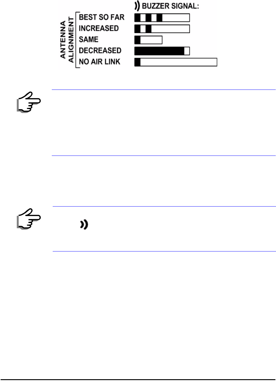
7. Slowly turn the site A antenna back towards the position of site B, listen-
ing to the tone until the best signal is reached. See the following figure
for audible signal variations.
Figure 3-11: Beep Sequence for antenna alignment
8. Secure the site A antenna to the pole/wall.
9. Repeat steps 4 to 8 for site B.
¾To align two external monopolar antennas:
1. Using a coax cable with N-Type connectors, connect one antenna to the
ANT 1 connector of the ODU.
2. Follow the steps 3 to 7 above to align the antenna connected to the ODU
connector ANT 1 on both sides of the link.
3. On both sides of the link, disconnect the antenna connected to the ODU
connector ANT 1. Connect the other antenna to connector ANT 1 and fol-
low the steps 3 to 7 above to align the second antenna.
4. Secure the antennas to the pole/wall.
5. Restore one of the antennas to ANT 2 on both sides of the link.
Note
• Three beeps and a pause is 'best signal so far'
• Two beeps and a pause is 'signal quality increased'
• One beep and pause is 'no change in signal'
• Long beep and short pause is 'signal quality decreased'
• One beep and a long pause is 'no air link'
• Any other signal does not relate to antenna alignment
Note
The ODU buzzer only works on the radio connected to the ANT 1 connector
marked . You will therefore need to use ANT 1 to align both antennas
in turn. Upon completion of the alignment procedure, you may connect the
two antennas to ANT 1 and ANT 2 connectors.

RADWIN 1000/2000 User Manual Version 2.12 4-1
Chapter 4
Link Installation: The
RADWIN Manager
This chapter explains how to use the RADWIN Manager to install a radio
link.
Installing theRADWIN Manager Application
Minimum System Requirements
The RADWIN Manager application is distributed on a CD. Operating system
specific PC resources required by the application are set out in table 4-1
below:
Requirements common to all systems are:
• Hard disk: 1 GB free space
• Network: 10/100BaseT NIC
• Graphics: 1024x768 screen resolution with 16 bit color
• Microsoft Explorer version 5.01 or later
Installing the Software
¾To install the RADWIN Manager application:
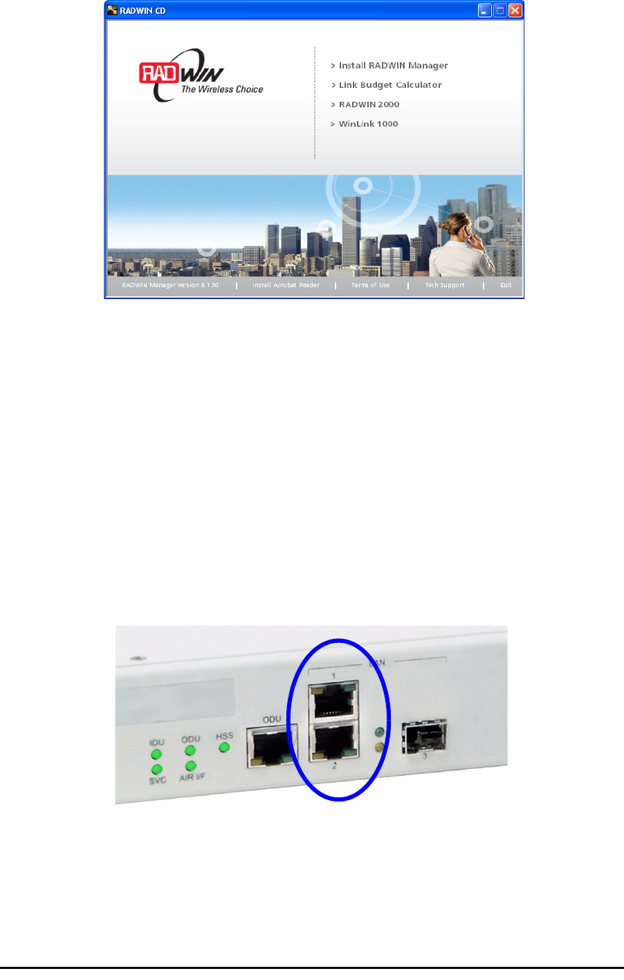
1. Insert the CD into the CD/DVD drive of your computer.
The CD opening screen appears:
Table 4-1: PC Requirements for the RADWIN Manager Application
Windows 2000 Windows XP Pro Windows Vista
Memory 128 MB 512 MB 1 GB
Processor P III P IV P IV Dual Core
Starting the RADWIN Manager Chapter 4
RADWIN 1000/2000 User Manual Version 2.12 4-2
2. Choose Install RADWIN Manager and follow the on-screen instructions
of the installation wizard to complete the setup of the RADWIN Manager
application.
If the installation program fails to start, browse to your CD/DVD drive,
chose the setup.exe program and run it.
Any PC running the RADWIN Manager application can be used to configure
a RADWIN 1000/2000 link.
Starting the RADWIN Manager
¾To start the RADWIN Manager:
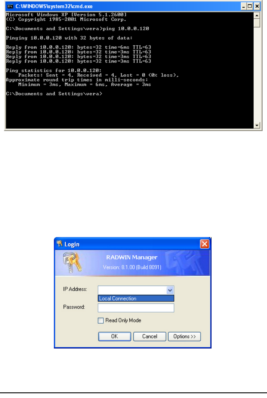
1. Connect the managing computer to one of the two LAN ports as shown
in figure 4-1 below:
Figure 4-1: LAN ports on the front panel of the IDU-C
If you are not using a direct connection as above, ensure that you have
IDU to managing computer connectivity (e.g. through a LAN).
2. Check that you have connectivity to the ODU. You can do this by opening
up a command line session (Start|Run and then type, cmd). At the
command prompt, type
Starting the RADWIN Manager Chapter 4
RADWIN 1000/2000 User Manual Version 2.12 4-3
ping 10.0.0.120
You should see something like this:
Figure 4-2: Pinging an uninstalled and unconfigured link
Any other response from ping means that the ODU is not responding.
Check your Ethernet connection and that both the the IDU and ODU are
switched on and then try again. If you do not succeed, seek assistance
from RADWIN Customer Support.
3. Dismiss the command line session.
4. Double-click the RADWIN Manager icon on the desktop, or click
Start|Programs|RADWIN Manager|RADWIN Manager.
The Login dialog box appears.
Figure 4-3: Login Screen
5. Type an IP address for the ODU (if you connect through a network), or
click Local Connection (if you are connected directly to the IDU port).

Starting the RADWIN Manager Chapter 4
RADWIN 1000/2000 User Manual Version 2.12 4-4
6. Enter the password
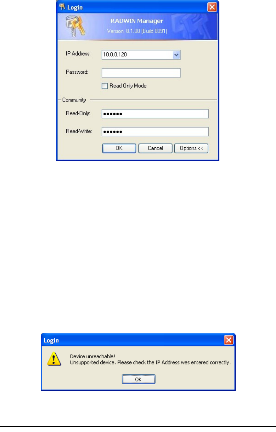
7. If you are a user with Read-Write permission, click Options to enter the
Community options.
Warning
1. If you log in on Local Connection, but your physical connection is
not local (i.e. anything other than a direct connection between
the managing computer and the IDU), then any configuration
you carry out may affect other links in the network.
2. If you log in via an over-the-air IP address, you will receive a
warning. If you reset the site to which you are connected to
factory settings, you can lock yourself out of the Link.
3. Network login (IP address to the ODU) is recommended.
Note
The default IP address for the ODU is 10.0.0.120. The subnet mask is
255.0.0.0.
The actual IP address is defined during link configuration (see Site
Management: IP Address and VLAN on page 6-4).
Note
The default password is
admin
(see Changing the Log On Password on
page 4-7).
Note
RADWIN 1000/2000 is protected with Community passwords. A user may be
defined with read-only permission or with read-write permission (see
page 6-14 for more details).
Login Errors Chapter 4
RADWIN 1000/2000 User Manual Version 2.12 4-5
Figure 4-4: Login Screen with Community options visible
• If you are using the system for the first time, leave the default Com-
munity passwords,
netman
for read-write, and
public
for read-
only.
• If Community values were previously defined, enter them under
Community in the Read-Only or Read-Write boxes.
• If you are a user with read-only permission, click the Read Only
Mode check box.
The RADWIN Manager main window is displayed (see figure 4-7).
Login Errors
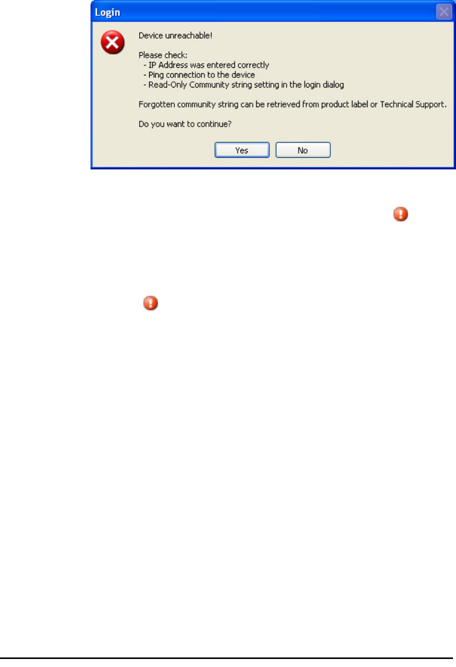
Unsupported Device
Attempting to connect to an unsupported device will result in the following
error message:
Figure 4-5: Unsupported device message
Incorrect IP Address Chapter 4
RADWIN 1000/2000 User Manual Version 2.12 4-6
Incorrect IP Address
If the IP address chosen is invalid or the link is unreachable, the following
error message will be displayed:
Figure 4-6: Unreachable device message
In both of the above situations, you will see a warning graphic along-
side the IP Address field.
Incorrect Password
If you type an incorrect password in the Login screen, you will see a warn-
ing graphic alongside the password field.
Continuing without an IP Address
The RADWIN Manager provides limited “offline” functionality when there is
no accessible IDU/ODU. It is primarily for setting managing computer
related parameters and running the Link Budget Calculator. The offline func-
tionality is shown in table 4-2 below. The table does not show menu items
grayed out.

Changing the Log On Password Chapter 4
RADWIN 1000/2000 User Manual Version 2.12 4-7
Changing the Log On Password
¾To change the log on password:
1. From the Tools menu, select Change Password.
The Change Password dialog box appears.
2. Enter the current password, and the new password.
3. Click OK to confirm.
Installing the Link: First steps
At this point the main window of the RADWIN Manager should be displayed:
Table 4-2: RADWIN Manager: Offline Functionality
Menu level
Function Reference
Top +1 +2
File
Log Off Return to Log On dialog.
Same as Log Off button
Exit Exit the RADWIN Manager.
Same as Exit button
Tools
Change
Password
Change the Log On pass-
word dialog page 4-7
Events Log page 7-10
Clear
Events
Clear local events log
Save to
File
Save events log data to a file
Help
RADWIN
Manager
Help
View online help version of
the User Manual
Link Budget
Calculator
Calculator opened in default
browser Appendix D
Get
Diagnostics
Information
Obtain system information page 7-1
About
RADWIN
Manager
RADWIN Manager build
information
Installing the Link: First steps Chapter 4
RADWIN 1000/2000 User Manual Version 2.12 4-8
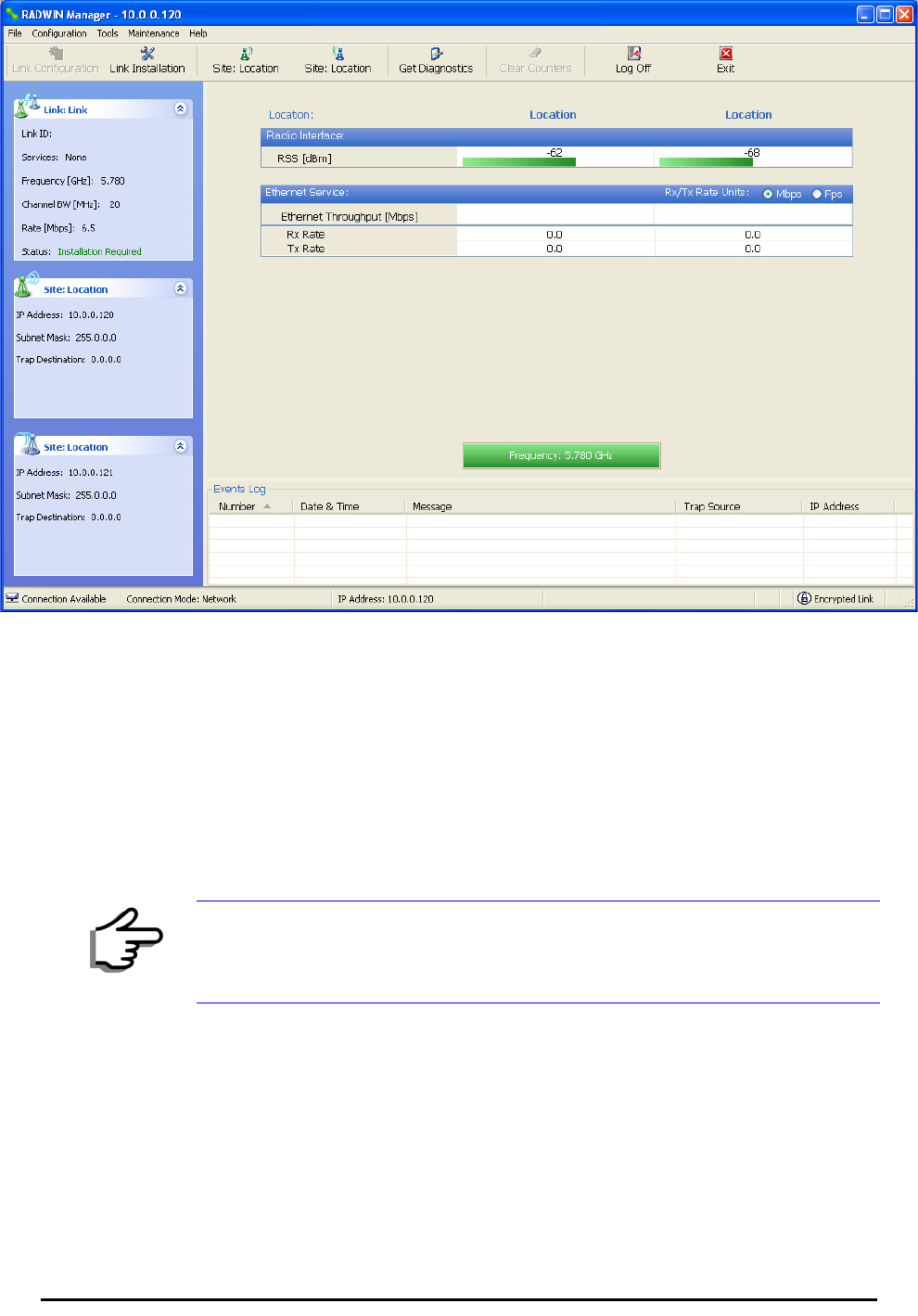
Figure 4-7: Opening RADWIN Manager window prior to installation
A detailed field by field description of the contents of the RADWIN Manager
main window may be found in chapter 5.
The procedure required to make the link functional has three phases:
1. Link Installation - which we will detail below.
Installation actually gets the link operational by setting the link parame-
ters. It uses a fixed channel at the lowest possible modulation, BPSK at
6.5Mbps and will work under the harsh interference condition.
2. Link Configuration - described in chapter 5.
Configuration provides much the same functionality as Installation, but
for a running link. A fallback to Installation mode is provided for situa-
tions which cannot be handled without resetting the link, such as
antenna realignment and IDU or ODU replacement.
The Link Installation and Configuration phases are both carried out with
Wizards, which “walk you through” the processes. The Wizards are visu-
ally quite similar and will be described in detail below.
Note
During the installation procedure, the definition of all parameters is
automatically applied to both sides of the link.

Default Settings Chapter 4
RADWIN 1000/2000 User Manual Version 2.12 4-9
3. Site Configuration - described in chapter 6.
Site specific configuration for each side of the link is available at any time
- under a running link or under the restricted Installation mode.
Site Configuration consists of a set of panels, which may be invoked indi-
vidually in any order, as needed.
Default Settings
The default settings of the RADWIN 1000/2000 configuration parameters
are listed in table 4-3 below:
Front Panel LEDs on the IDU-C
The front panel LEDs on the IDU provide basic information about link sta-
tus.
Note
An installed and configured link can be returned to installation mode for re-
installation and configuration from last settings or from factory settings.
• Reversion to installation mode requires a complete break in the link
service
• Configuration mode may vary the service throughput and quality, but
without a service break
Table 4-3: Default Settings
Parameter Default Value
ODU IP Address 10.0.0.120
Subnet Mask 255.0.0.0
Trap destination 0.0.0.0
Manager Login password admin
Link ID Link
Site 1 Site
Site 2 Site
Link Password wireless-bridge
Rate Adaptive
Ethernet Configuration Auto Detect
Radio Link Failure Actions No action
Bridge or Hub mode Hub Mode, Aging time = 300 sec
Community values Read-write – netman
Read-only – public
Installation Menu and Toolbar Functionality Chapter 4
RADWIN 1000/2000 User Manual Version 2.12 4-10
Figure 4-8: IDU-C Front Panel LEDs
The following table describes the indicators:
Installation Menu and Toolbar Functionality
The RADWIN Manager menu functionality is displayed in table 4-5. The
Toolbar buttons are detailed in table 4-6.
Table 4-4: Front Panel LEDs
Name Color Function
IDU
With Ethernet only
Green
Green
Red
During power-up only
IDU operational
Failure
ODU Green
Red
ODU-to-IDU communication link is operating
ODU-to-IDU communication link is disrupted
AIR I/F Green
Orange
Red
Wireless link is synchronized
During installation mode only
Wireless link lost synchronization
SVC Off
HSS Off

Installation Menu and Toolbar Functionality Chapter 4
RADWIN 1000/2000 User Manual Version 2.12 4-11
Table 4-5: RADWIN Manager main menu functionality
Menu level
Function Reference
Top +1 +2
File
Log Off Return to Log On dialog.
Same as Log Off button
Exit Exit the RADWIN Manager.
Same as Exit button
Configuration
Link
Configuration
Run the Configuration Wiz-
ard. Not available in
installation mode
1 Configure
<Site 1 name>
Provides limited configura-
tion for site. Has a path to
return to installation
mode
2 Configure
<Site 2 name>
Provides limited configura-
tion for site. Has a path to
return to installation
mode
Link Installation
Runs the Installation Wiz-
ard. Not available in
configuration mode
Tools
Performance
Monitoring
Report
Active Alarms
1 <Site 1 name> Shows active alarms for
<Site 1 name>
2 <Site 2 name> Shows active alarms for
<Site 1 name>
Change
Password
Change the Log On pass-
word dialog page 4-7
Events Log
page 7-10
Clear Events Clear local events log
Save to File Save events log file
Preferences Local preferences dialog

Installation Menu and Toolbar Functionality Chapter 4
RADWIN 1000/2000 User Manual Version 2.12 4-12
Maintenance
Clear counters Disabled
Loopbacks Disabled
Reset 1 <Site 1 name> Reset <Site 1 name> ODU
2 <Site 2 name> Reset <Site 2 name> ODU
Help
RADWIN
Manager Help
View online version of the
User Manual
Link Budget
Calculator
Calculator opened in
default browser Appendix D
Get Diagnostics
Information
Obtain system information page 7-1
About RADWIN
Manager
Manager build and system
information
Table 4-6: RADWIN Manager Toolbar
Item Description
Link Configuration Changes configuration parameters of an operating wireless link;
assigns text files for storing alarms, statistics and configuration
data. This button is disabled until a link installation has
been completed
Link Installation Performs preliminary configuration of the system. This button is
disabled after the link is installed
Site: <Site 1 name> Opens the Site configuration dialog for Site A. Same as
Configuration | 1 Configure <Site 1 name>
Site: <Site 2 name> Opens the Site configuration dialog for Site B. Same as
Configuration | 2 Configure <Site 2 name>
Get Diagnostics Obtain system information
Clear Counters Disabled
Log off Closes the current session and logs off RADWIN Manager
Exit Exits RADWIN Manager
Table 4-5: RADWIN Manager main menu functionality (Continued)
Menu level
Function Reference
Top +1 +2
Installing the Link: Overview Chapter 4
RADWIN 1000/2000 User Manual Version 2.12 4-13
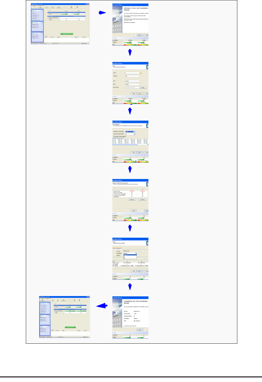
Installing the Link: Overview
The Installation wizard has seven steps as shown in table 4-7 below.
Table 4-7: Link Installation Wizard
1Wizard welcome
2
System parameters
•Link ID
• Site details
3Channel settings - ACS
Configuration
4Tx power and antenna
settings
5Services - Adaptive or
fixed
6Wizard summary and
completion
Installing the Link: Step 1, Start the Wizard Chapter 4
RADWIN 1000/2000 User Manual Version 2.12 4-14
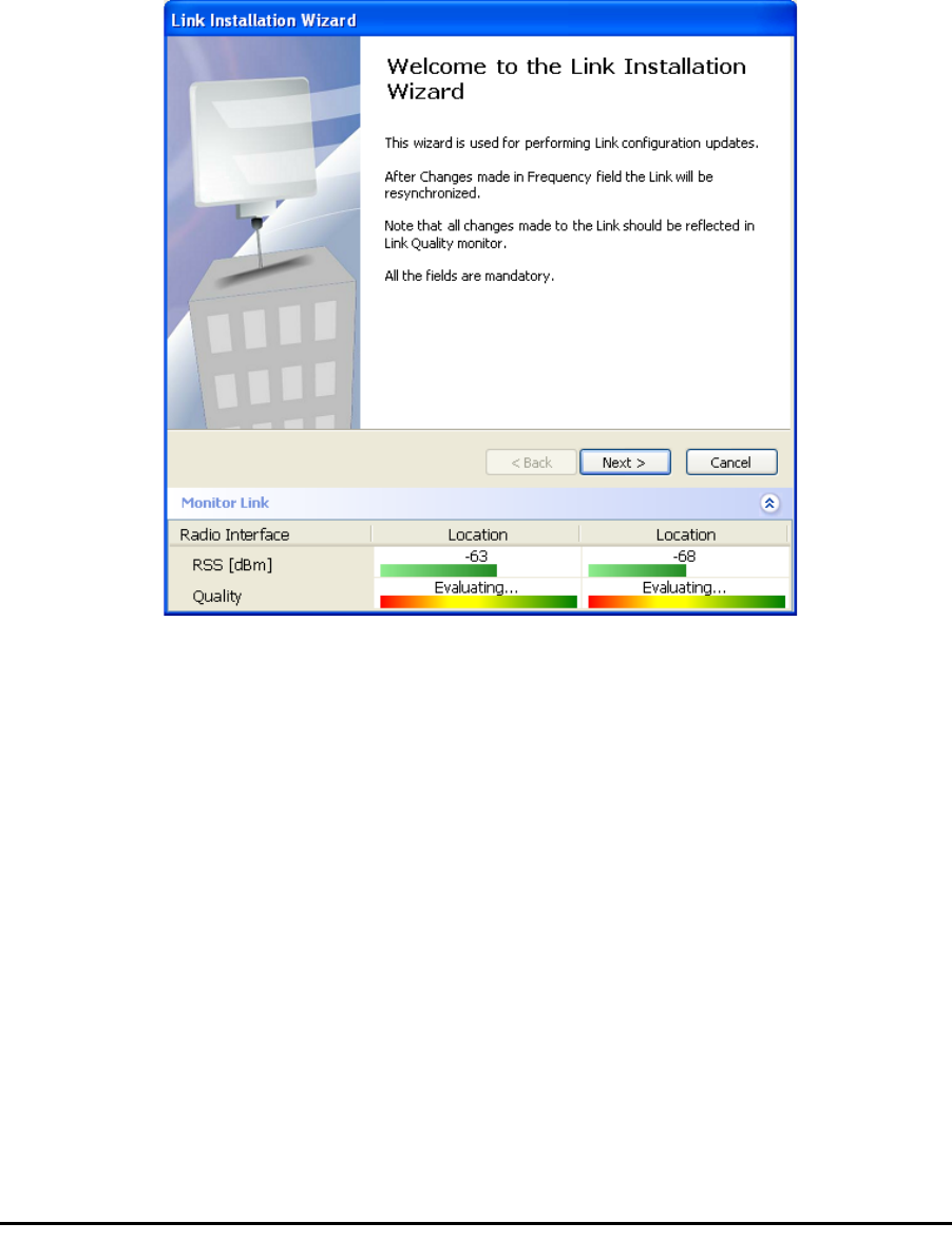
Installing the Link: Step 1, Start the Wizard
In the tool bar of the RADWIN Manager main window, click the Link
Installation button. The Link Installation button is only accessible if anten-
nas are properly aligned. If this box is “grayed out”, you should align the
antennas as set out in Connecting and Aligning ODUs / Antennas on
page 3-12.
The Installation Wizard opens:
Figure 4-9: Link Installation Wizard
The bottom data area reproduces the corresponding data from the main
window - which the above panel obscures. See page 5-7 for a field by field
description of this data area.
Click Next to proceed with the installation procedure.
Installing the Link: Step 2, System Parameters
The system dialog box opens:
Installing the Link: Step 2, System Parameters Chapter 4
RADWIN 1000/2000 User Manual Version 2.12 4-15
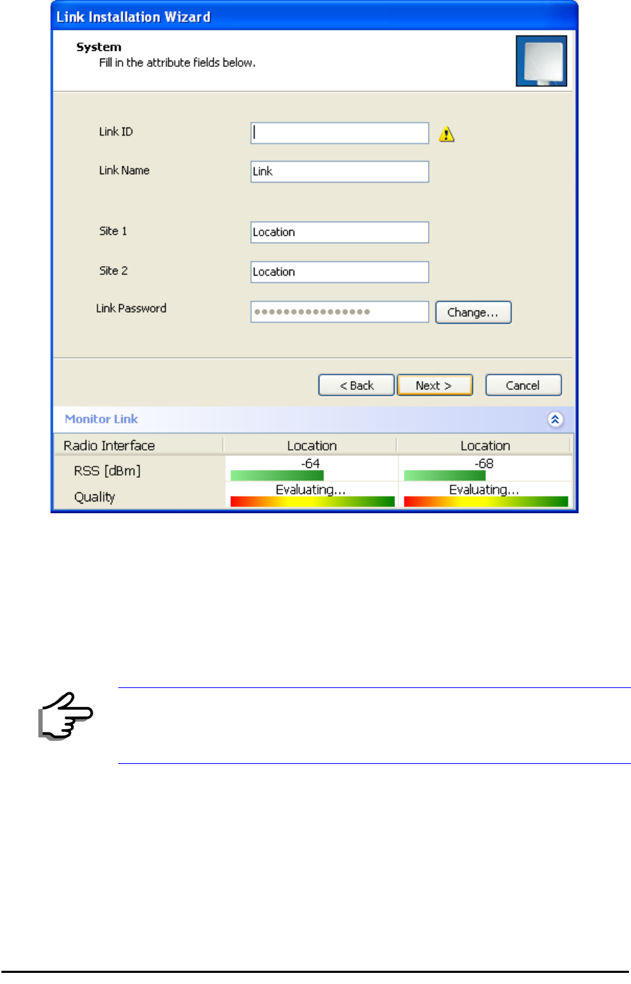
Figure 4-10: : Installation Wizard, System dialog box
¾To complete Installation Step 2:
1. Enter a Link ID. (Link ID - must be unique for each link in the area). The
Link ID must include at least eight alphanumeric characters. Up to 24
characters are allowed.You should use a Link ID composed of both
alphabetic and numeric characters.
2. Enter a Link Name for the link identification. The default name is “Link”.
You should change it.
3. Enter names for Site 1 and Site 2. The default names are both “Loca-
tion”. You should change them. Throughout this manual, we use A for
Site 1 and B for Site 2.
Note
Both sides of a link must have the same Link ID.
Changing the Link Password Chapter 4
RADWIN 1000/2000 User Manual Version 2.12 4-16
4. Optionally enter a new Link Password.
5. Click Next.
The default link with a rate of 6.5 Mbps is evaluated.
The Channel Setting dialog box appears. Proceed to Installing the
Link: Step 3, Channel Settings, below.
Changing the Link Password
The default password is
wireless-bridge
. Optionally, you can change the
link password as explained here.
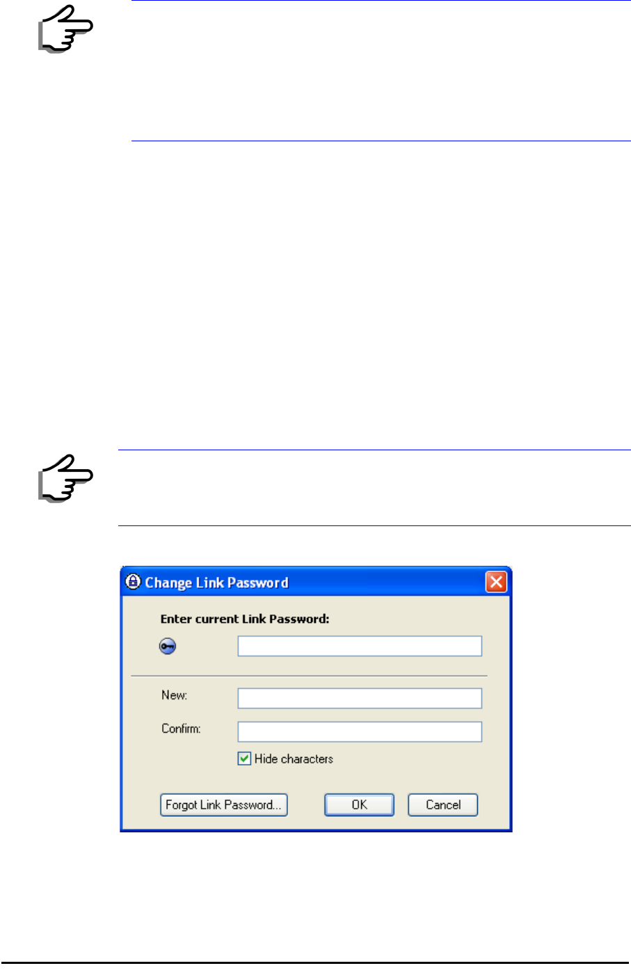
¾To change the link password:
1. Click the Change button in the System dialog box.
The Change Link Password dialog box opens.
Figure 4-11: Change Link Password dialog box
2. Enter the current link password (The default link password for a new
ODU is wireless-bridge).
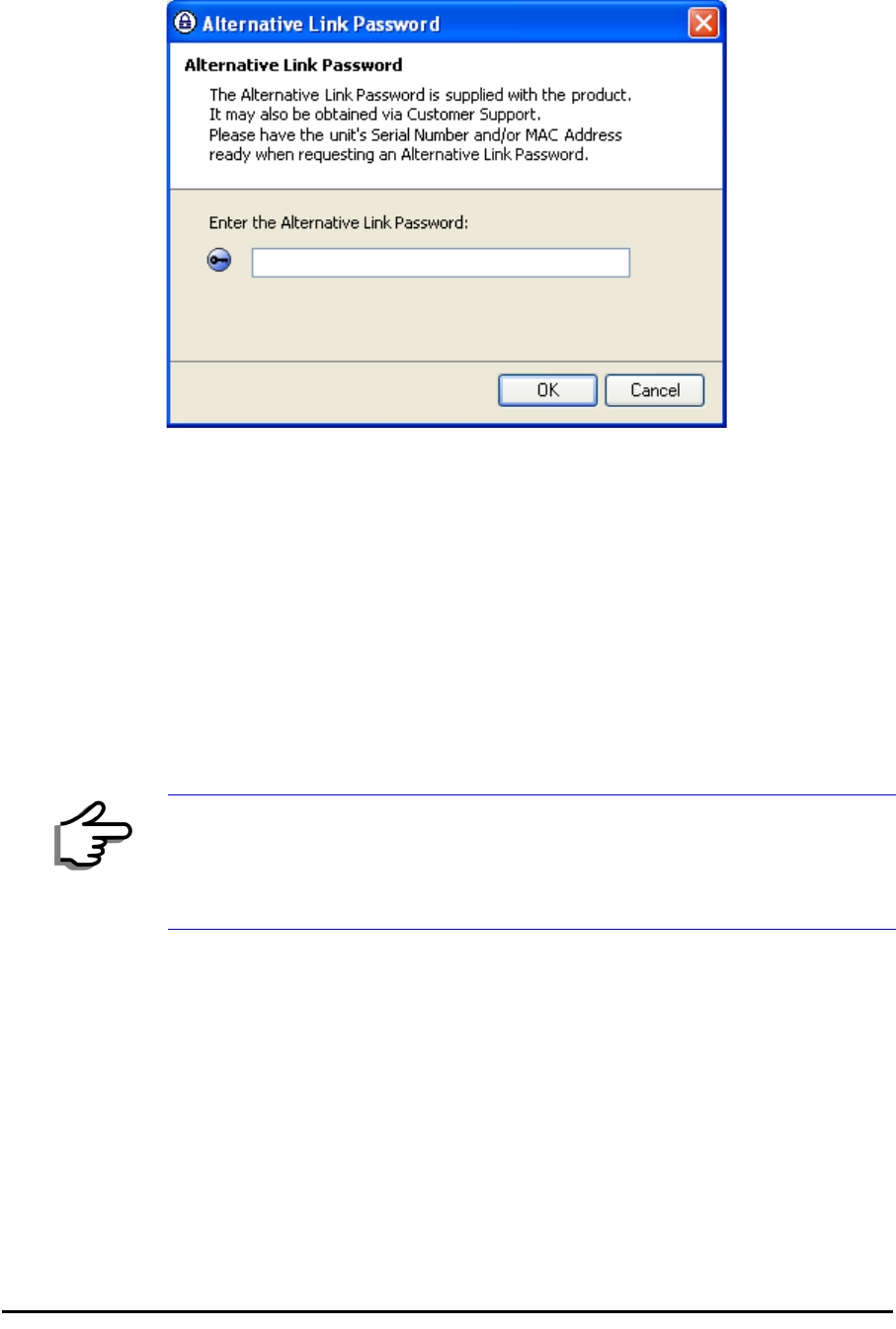
Note
If the Link Password is incorrect a link is established but configuration
cannot be performed and no services are available. A new link password
may be obtained from RADWIN Customer Support or use the alternative
password supplied with the product. (see for more details).
The link password is peculiar to the link itself and should not be confused
with the RADWIN Managerlog on password.
Note
Use the Hide characters check box for maximum security
Installing the Link: Step 3, Channel Settings Chapter 4
RADWIN 1000/2000 User Manual Version 2.12 4-17
If you have forgotten the Link Password, click the Forgotten Link Pass-
word button. The following window is displayed:
Figure 4-12: Lost or forgotten Link Password recovery
Follow the instructions to use the Alternative Link Password, and click
OK to finish. You are returned to the window in figure 4-11 above.
Continue with the next step.
3. Enter a new password.
4. Retype the new password in the Confirm field.
5. Click OK.
6. Click Yes when asked if you want to change the link password.
7. Click OK at the Password changed success message.
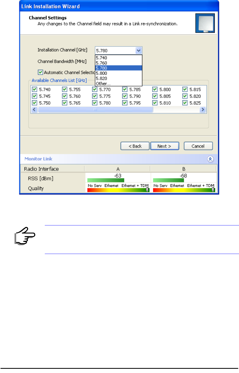
Installing the Link: Step 3, Channel Settings
RADWIN 1000/2000 systems have a feature called Automatic Channel
Selection (ACS). In the event of sync loss, ACS chooses the first available
channel in a list of monitored channels nominated in the Channel settings
window of figure 4-13 below. A channel switch takes place sufficiently fast
as to ensure no loss of service.
Note
• Restoring Factory Defaults returns the Link Password to
wireless-
bridge
.
• If the link is inactive, then the link password may also be changed
from the Site Configuration dialogs. See page 6-14.
Installing the Link: Step 3, Channel Settings Chapter 4
RADWIN 1000/2000 User Manual Version 2.12 4-18
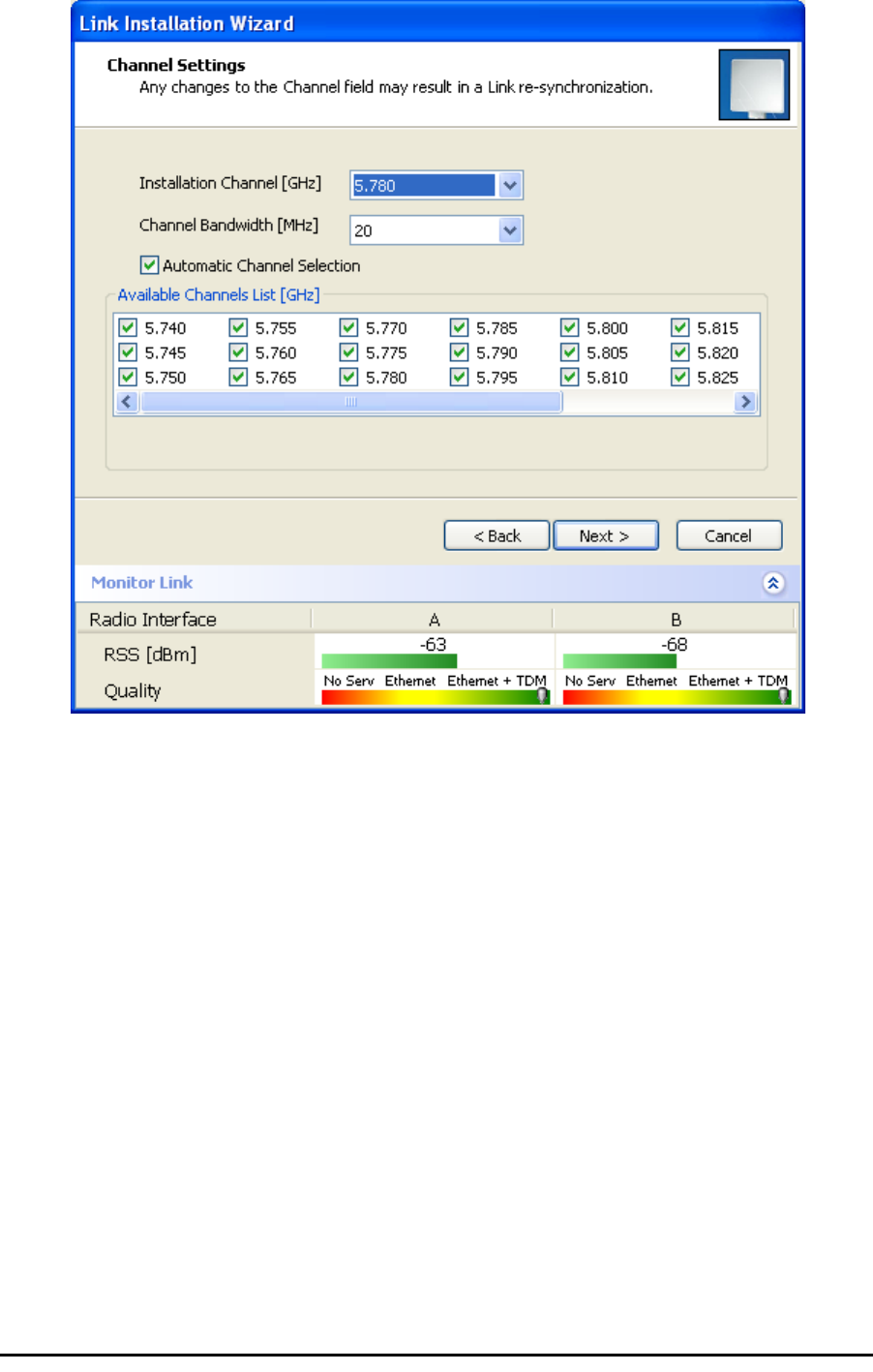
Figure 4-13: Channel Settings - Automatic Channel Selection
The default frequency for the product is shown.
¾To select channels to be used by the link:
1. Select the main frequency from the Installation Channel box.
Installing the Link: Step 4, Tx Power and Antenna Settings Chapter 4
RADWIN 1000/2000 User Manual Version 2.12 4-19
Figure 4-14: Channel Settings - Showing available installation rates
2. Click the check box if Automatic Channel Selection is required.
3. The Available Channels List contains all of the allowable channels for the
link. Check the channels that can be automatically selected.
Selecting a new channel causes the system quality to change. The Qual-
ity bar provides an indication of the link quality from poor (red) to good
(green) as shown in the bottom of figure 4-13 above.
4. Click Next.
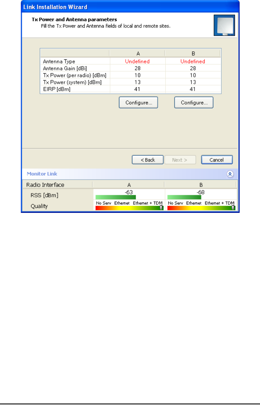
Installing the Link: Step 4, Tx Power and Antenna Settings
The Tx Power and Antenna Parameters dialog appears.
Note
For version 2.1, channel bandwidth is set to 20 MHz and cannot be
changed.
General Chapter 4
RADWIN 1000/2000 User Manual Version 2.12 4-20
.
Figure 4-15: Transmission Power and Antenna Parameters
The choice of Tx power, antenna gain and cable loss determines the EIRP
and is affected by such considerations as radio limitations and regulatory
restrictions.
Before proceeding to antenna installation details, the following background
information should be considered:
General
Each RADWIN 1000/2000 ODU is made of two radio transceivers (radios).
The radios make use of algorithms that utilize both polarization and space
diversity resulting in enhanced capacity, range and link availability. The
number of antennas (i.e. radios) used is determined by user configuration
and by automatic system decisions, explained below.
Dual Antennas at Both Sites
Using dual antennas at both sites (single bipolar antenna or two monopolar
antennas) enables the use of MIMO technology. With MIMO the system
doubles the link capacity. At the same time, it keeps the same rate and
modulation per radio as was used with single antenna, thus increasing
capacity, range and availability.

Single Antennas at Both Sites Chapter 4
RADWIN 1000/2000 User Manual Version 2.12 4-21
For example with a dual antenna RADWIN 1000/2000 can transmit at mod-
ulation of 64QAM and FEC of 0.83 and get an air rate of 130 Mbps, com-
pared to 65 Mbps with single antenna.
To work in this mode, each antenna port must be connected to an antenna,
the RSS level in both receivers should be balanced and a minimal separation
between the antennas must be maintained. (For example, by using dual
polarization antennas a cross polarization separation is attained).
Upon selecting Antenna Type as Dual, RADWIN 1000/2000 automatically
doubles the air rates.
RADWIN Manager indicates a case of unbalanced RSS between the two
antennas.
Single Antennas at Both Sites
By selecting a single antenna at both sites the ODUs operate with a single
radio that is connected to the ANT 1 connector. The second radio is auto-
matically shut down.
Single and Dual Antennas
In this mode one of the sites uses the ODU with a single antenna while the
other site uses the ODU with a dual antenna.
The advantages in this mode in comparison to using a single antenna in
both sites are doubled total Tx power and additional polarization and/or
space diversity.
RADWIN 1000/2000 automatically switches to this mode if one of the ODUs
is connected to a dual antenna or if the RSS at one of the ODU receivers is
below minimal level.
The air rates used in this mode are same as when using single antennas in
both sites.

Considerations for Changing Antenna Parameters Chapter 4
RADWIN 1000/2000 User Manual Version 2.12 4-22
The rates used by RADWIN 1000/2000 are shown in Table 4-5 below:
Considerations for Changing Antenna Parameters
Let:
maxAllowedTx Power denote the maximum Tx Power practically avail-
able from an ODU. It appears as Tx Power per Radio in
figure 4-16 below.
maxRegEIRP denote the maximum EIRP available by regulation. It will be
determined by three factors:
• per band/regulation
• per channel bandwidth
•antenna gain
It appears in figure 4-16 as Max EIRP.
maxRegTxPower denote the maximum regulatory Tx Power for the
equipment, also having regard the above three points
Table 4-8: RADWIN 1000/2000 Transmission rates
Radio Modulation FEC Air-Rate
[Mbps]
Single BPSK 1/2 6.5
Single QPSK 1/2 13
Single QPSK 3/4 19.5
Single 16QAM 1/2 26
Single 16QAM 3/4 39
Single 64QAM 2/3 52
Single 64QAM 3/4 58.5
Single 64QAM 5/6 65
Dual BPSK 1/2 13
Dual QPSK 1/2 26
Dual QPSK 3/4 39
Dual 16QAM 1/2 52
Dual 16QAM 3/4 78
Dual 64QAM 2/3 104
Dual 64QAM 3/4 117
Dual 64QAM 5/6 130
Considerations for Changing Antenna Parameters Chapter 4
RADWIN 1000/2000 User Manual Version 2.12 4-23
maxODUTxPower denote the maximum Tx Power of the ODU, itself
depending on the air rate used.
Then, the following relationship must be satisfied:
... (*)
These parameters are controlled as follows:
¾To set Tx power and configure antennas:
1. Click the Configure buttons in turn to configure the antennas on both
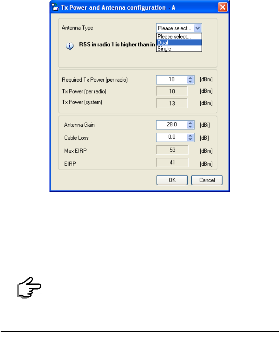
sides of the link. Each one offers a dialog like this:
Figure 4-16: Antenna configuration dialog with opened type selection
2. Choose the antenna type and required transmission (Tx) power for the
first site and click OK. Repeat the process for the second site.
The Tx power (per radio) indicates the power of each radio inside the
ODU and is used for Link Budget Calculations. The Tx power (System)
shows the total transmission power of the ODU and is used to calculate
the EIRP according to regulations.
Note
To see the relationship between Tx Power (radio) and TX Power (system),
note that so that if you double the power in
milliWatts (for two radios) then dBm will increase by .
maxAllowedTxPower min maxRegEIRP
AntennaGain CableLoss maxRegTxPower,+–
(
)
≤
dBm 10 milliWatt
10
log×=
10 2 3≈
10
log×
Considerations for Changing Antenna Parameters Chapter 4
RADWIN 1000/2000 User Manual Version 2.12 4-24
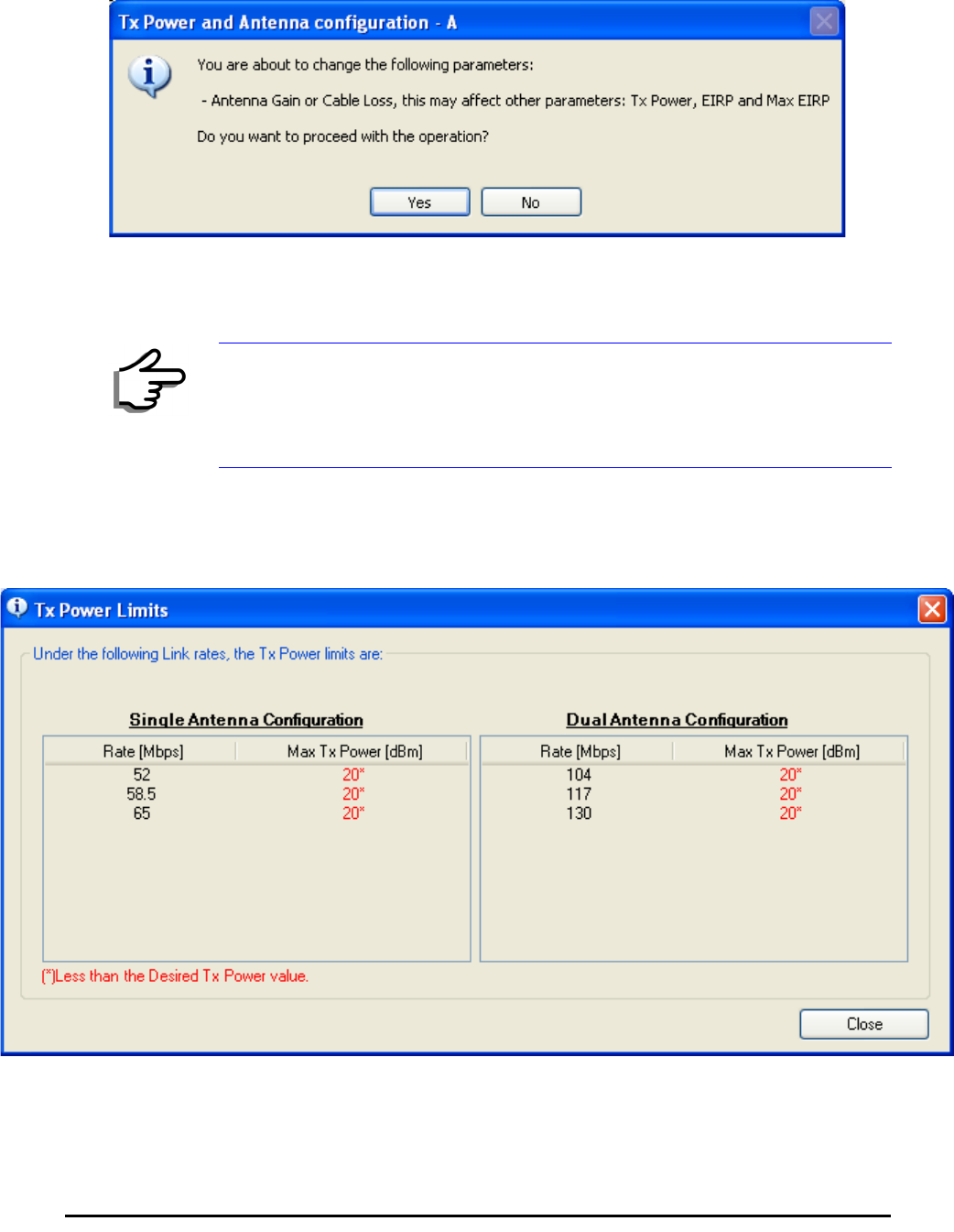
3. Set the Antenna Gain and Cable Loss. If do this you will receive a warn-
ing message:
Figure 4-17: Antenna parameters change warning
If inequality (*) above is violated, then the following warning window is
displayed:
Figure 4-18: Tx Power Limits
The precise relationship between the items in inequality (*) and the win-
dow of figure 4-16 is follows:
Note
• The Max EIRP level will be automatically set according to the selected
band and regulation.
• The EIRP level is the sum of the System Tx power and the Antenna
Gain minus the Cable Loss.
Installing the Link: Step 5, Services Chapter 4
RADWIN 1000/2000 User Manual Version 2.12 4-25
• Required Tx Power (per radio) will be adjusted down to the
lesser of the value entered and maxAllowedTxPower
•TxPower (system)is maxAllowedTxPower + 3 (for 2 radios)
•Max EIRP is maxRegEIRP.
•EIRP is maxAllowedTx Power + Antenna Gain - Cable
Loss
The table in figure 4-18 only shows rates where the maximum Tx
Power is the limitation, rather than regulations.
When you close the window of figure 4-18, the change you requested
will not be honored, and you will need to try again.
4. When you are finished with Tx Power configuration, Click Next.
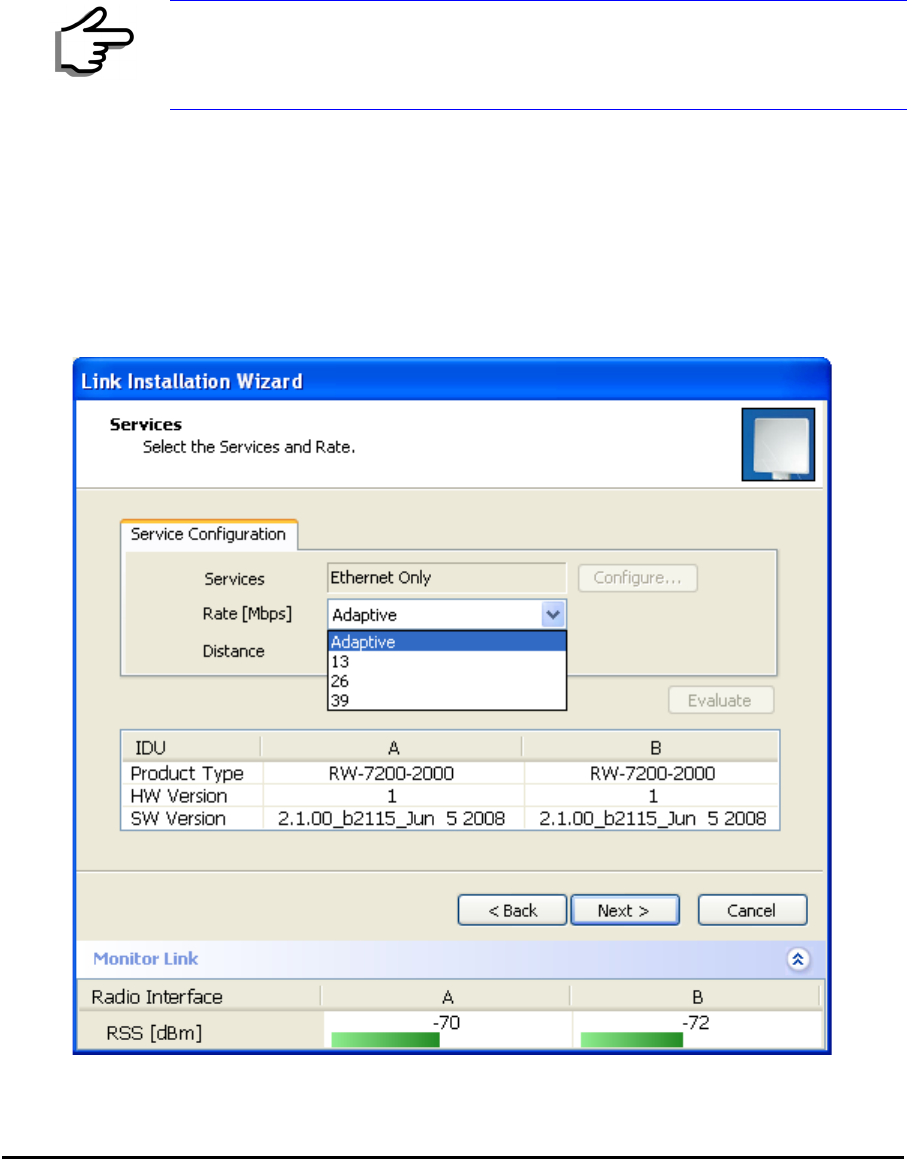
Installing the Link: Step 5, Services
The Services dialog appears:
Figure 4-19: Services and Rates dialog
Note
Recall that maxAllowedPower and maxEIRP are regulatory. In an
unregulated environment, the only limit is maxODUTxPower.
Installing the Link: Step 6, Installation Summary and Exit Chapter 4
RADWIN 1000/2000 User Manual Version 2.12 4-26
For version 2.1, Ethernet Only is the only available service. You may choose
a specific modulation rate or use Adaptive.
¾To choose a modulation rate:
1.Choose Adaptive or one of the available rate (see page 1-3 for informa-
tion about Automatic Adaptive Rate).
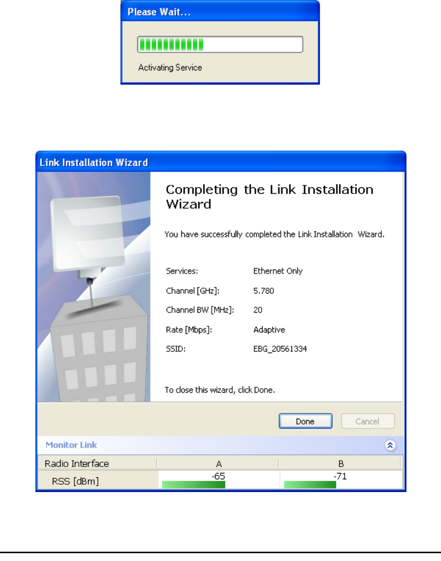
2. Click Next to continue.
The service is activated as show below:
Installing the Link: Step 6, Installation Summary and Exit
Figure 4-20: Installation Wizard Exit Summary
Click Done to return to the main window.
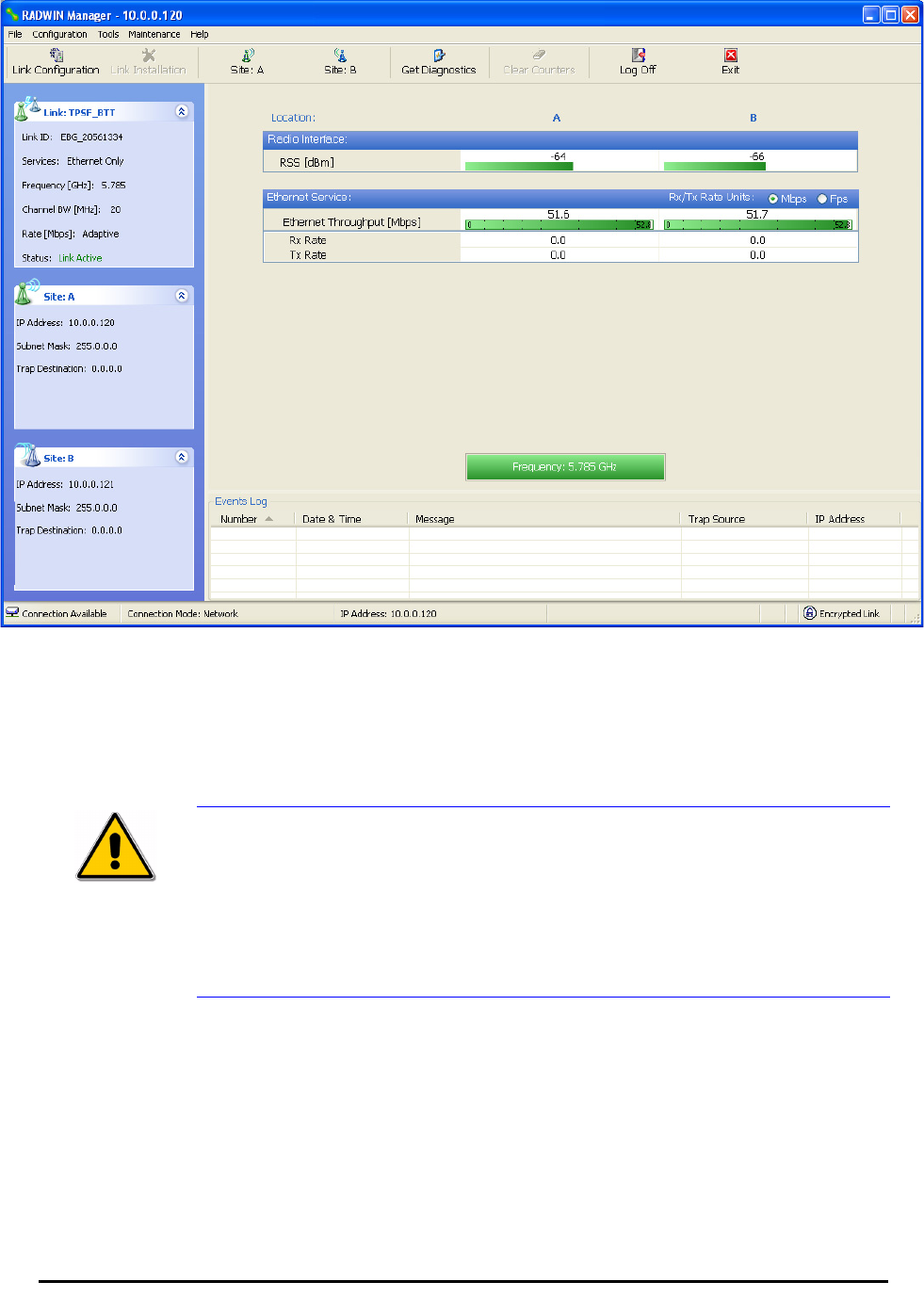
Installing the Link: Step 6, Installation Summary and Exit Chapter 4
RADWIN 1000/2000 User Manual Version 2.12 4-27
The main window now reflects the installation:
Figure 4-21: Main window of the manager after installation
¾To verify the installation:
• Verify that the Radio Signal Strength (RSS) is according to expected
results as determined by the Link Budget Calculator.
Caution
Installation mode, as described above, may be re-entered using
Configuration | 1 Configure Site A and Installation Mode the Site
Configuration dialog. Some Installation mode functionality may cause a
break in link service.
If you can accomplish link changes without breaking the service, always
prefer to use Configuration mode, described in chapter 5.