Railhead WING Wing Walker RF-Host Wireless alarm control box User Manual WingWalker G
Railhead Corporation Wing Walker RF-Host Wireless alarm control box WingWalker G
UserManual.wiki
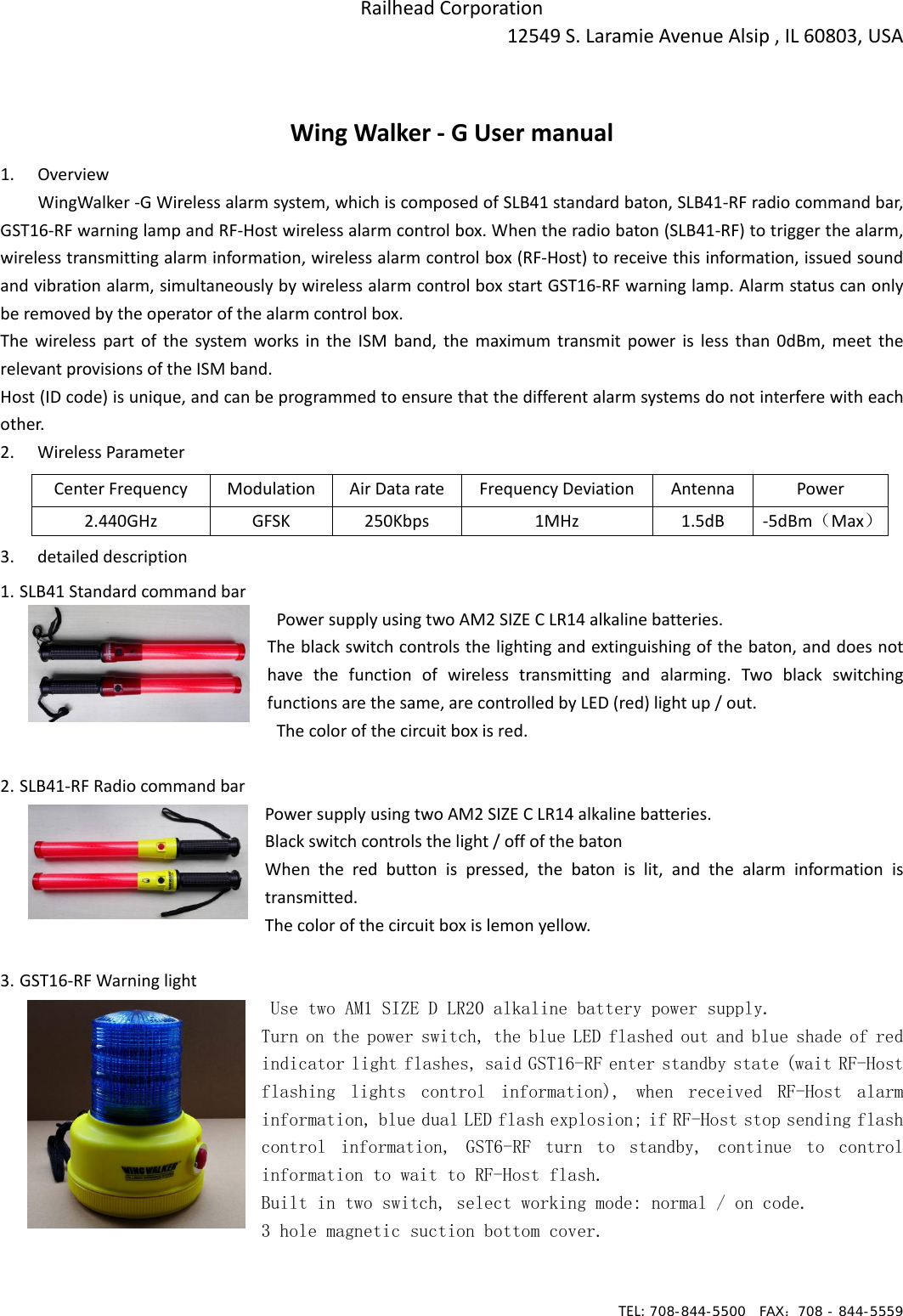
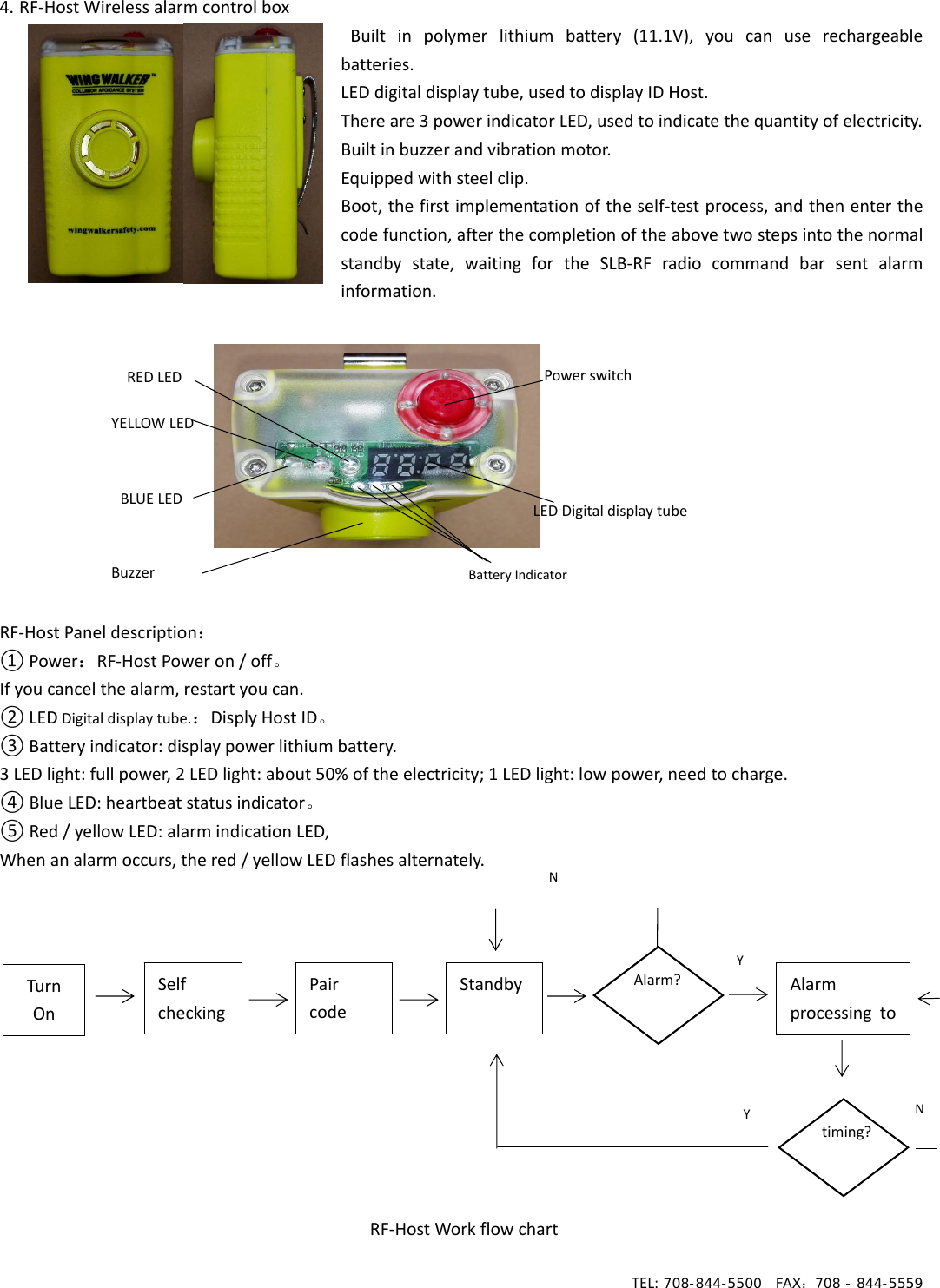
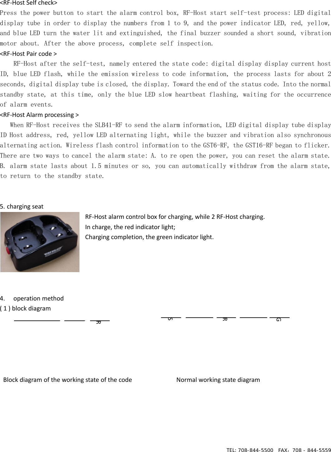
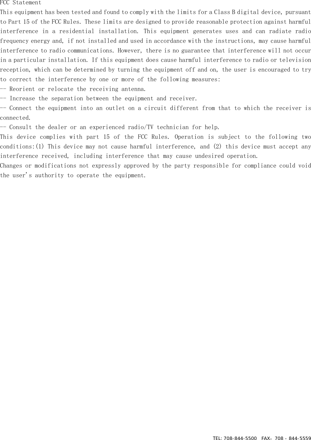
>
Railhead
>
WING User Manual
user manual
Navigation menu
Upload a User Manual
Namespaces
Wiki Guide
HTML
PDF
Info
Views
User Manual
Discussion / Help
Navigation