Raytheon Anschuetz High Seas GEMRM-10U X-Band Radar Transceiver User Manual Dokument
Raytheon Anschuetz GmbH High Seas Products X-Band Radar Transceiver Dokument
Contents
- 1. Users Manual Part 1
- 2. Users Manual Part 2
Users Manual Part 1
3464 100 – 037
NSC 18
Navigational Radar System
User Manual
3748DOC020102 Edition 14.JAN.2005

3748DOC020102
Weitergabe sowie Vervielfältigung dieser Unterlage, Verwertung und
Mitteilung ihres Inhaltes nicht gestattet, soweit nicht ausdrücklich
zugestanden. Zuwiderhandlungen verpflichten zu Schadenersatz.
Copying of this document, and giving it to others and the use or
communication of the contents thereof, are forbidden without express
authority. Offenders are liable to the payment of damages.
Toute communication ou reproduction de ce document, toute
exploitation ou communication de son contenu sont interdites, sauf
autorisation expresse. Tout manquement à cette règle est illicite et
expose son auteur au versement de dommages et intérêts.
Sin nuestra expresa autorización, queda terminantemente prohibida la
reproducción total o parcial de este documento, así como su uso
indebido y/o su exhibición o comunicación a terceros. De los infractores
se exigirá el correspondiente resarcimiento de daños y perjuicios.

Operator Manual Raytheon Marine GmbH
Germany
R
NSC 18
RADAR
Table of Contents
I3748DOC020102Edition: 14.JAN.2005
1 Introduction 1−4. . . . . . . . . . . . . . . . . . . . . . . . . . . . . . . . . . . . . . . . . . . . . . . . . . . . . . . . . . . . . .
1.1 Radar System 1−5. . . . . . . . . . . . . . . . . . . . . . . . . . . . . . . . . . . . . . . . . . . . . . . . . . . . . . . . . . . .
2 OPERATING INSTRUCTIONS 2−1. . . . . . . . . . . . . . . . . . . . . . . . . . . . . . . . . . . . . . . . . . . . . .
2.1 DISPLAY ORGANIZATION AND SUBMENU STRUCTURE 2−2. . . . . . . . . . . . . . . . . . . .
2.2 FIRST STEPS IN OPERATION 2−7. . . . . . . . . . . . . . . . . . . . . . . . . . . . . . . . . . . . . . . . . . . .
2.2.1 Switching ON 2−8. . . . . . . . . . . . . . . . . . . . . . . . . . . . . . . . . . . . . . . . . . . . . . . . . . . . . . . . . . .
2.2.2 How to use the CURSOR 2−10. . . . . . . . . . . . . . . . . . . . . . . . . . . . . . . . . . . . . . . . . . . . . . . . .
2.2.2.1 Cursor in park position 2−11. . . . . . . . . . . . . . . . . . . . . . . . . . . . . . . . . . . . . . . . . . . . . . . . . .
2.2.2.2 Cursor symbols 2−12. . . . . . . . . . . . . . . . . . . . . . . . . . . . . . . . . . . . . . . . . . . . . . . . . . . . . . . .
2.2.3 Radar operator panel 2−13. . . . . . . . . . . . . . . . . . . . . . . . . . . . . . . . . . . . . . . . . . . . . . . . . . . .
2.2.4 Softkeys and operator controls in NSC display 2−15. . . . . . . . . . . . . . . . . . . . . . . . . . . . . .
2.2.4.1 Softkeys in menu bar 2−15. . . . . . . . . . . . . . . . . . . . . . . . . . . . . . . . . . . . . . . . . . . . . . . . . . .
2.2.4.2 Operator controls in NSC display 2−17. . . . . . . . . . . . . . . . . . . . . . . . . . . . . . . . . . . . . . . . .
2.2.4.3 Toggle fields 2−18. . . . . . . . . . . . . . . . . . . . . . . . . . . . . . . . . . . . . . . . . . . . . . . . . . . . . . . . . . .
2.2.4.4 Sliders 2−18. . . . . . . . . . . . . . . . . . . . . . . . . . . . . . . . . . . . . . . . . . . . . . . . . . . . . . . . . . . . . . . .
2.2.4.5 Drag and drop 2−20. . . . . . . . . . . . . . . . . . . . . . . . . . . . . . . . . . . . . . . . . . . . . . . . . . . . . . . . .
2.2.5 System reset 2−21. . . . . . . . . . . . . . . . . . . . . . . . . . . . . . . . . . . . . . . . . . . . . . . . . . . . . . . . . . . .
2.2.6 Switching OFF the NSC radar system 2−22. . . . . . . . . . . . . . . . . . . . . . . . . . . . . . . . . . . . . .
2.3 DISPLAY OPERATIONS AND INDICATORS 2−24. . . . . . . . . . . . . . . . . . . . . . . . . . . . . . . . .
2.3.1 Sensitivity controls 2−25. . . . . . . . . . . . . . . . . . . . . . . . . . . . . . . . . . . . . . . . . . . . . . . . . . . . . . .
2.3.1.1 Gain and clutter processing 2−25. . . . . . . . . . . . . . . . . . . . . . . . . . . . . . . . . . . . . . . . . . . . . .
2.3.1.2 TUNE 2−25. . . . . . . . . . . . . . . . . . . . . . . . . . . . . . . . . . . . . . . . . . . . . . . . . . . . . . . . . . . . . . . . .
2.3.1.3 GAIN 2−27. . . . . . . . . . . . . . . . . . . . . . . . . . . . . . . . . . . . . . . . . . . . . . . . . . . . . . . . . . . . . . . . .
2.3.1.4 SEA 2−27. . . . . . . . . . . . . . . . . . . . . . . . . . . . . . . . . . . . . . . . . . . . . . . . . . . . . . . . . . . . . . . . . .
2.3.1.5 RAIN RATE 2−29. . . . . . . . . . . . . . . . . . . . . . . . . . . . . . . . . . . . . . . . . . . . . . . . . . . . . . . . . . . .
2.3.1.6 Filtering rain clouds FTC 2−30. . . . . . . . . . . . . . . . . . . . . . . . . . . . . . . . . . . . . . . . . . . . . . . .
2.3.1.7 CFAR 2−30. . . . . . . . . . . . . . . . . . . . . . . . . . . . . . . . . . . . . . . . . . . . . . . . . . . . . . . . . . . . . . . .
2.3.1.8 Search and rescue transponder SART ON/OFF (option) 2−31. . . . . . . . . . . . . . . . . . . . .
2.3.1.9 Pulse width selection 2−33. . . . . . . . . . . . . . . . . . . . . . . . . . . . . . . . . . . . . . . . . . . . . . . . . . .
2.3.1.10 Interference selection 2−34. . . . . . . . . . . . . . . . . . . . . . . . . . . . . . . . . . . . . . . . . . . . . . . . . . .
2.3.1.11 Echo expansion 2−34. . . . . . . . . . . . . . . . . . . . . . . . . . . . . . . . . . . . . . . . . . . . . . . . . . . . . . . .
2.3.2 Radar video displays 2−35. . . . . . . . . . . . . . . . . . . . . . . . . . . . . . . . . . . . . . . . . . . . . . . . . . . . .
2.3.2.1 Ship heading marker 2−35. . . . . . . . . . . . . . . . . . . . . . . . . . . . . . . . . . . . . . . . . . . . . . . . . . . .
2.3.2.2 Relative Motion (R), Relative Motion (T), True Motion 2−35. . . . . . . . . . . . . . . . . . . . . . .
2.3.2.3 North Up, Head Up, Course Up and Repeater Up 2−39. . . . . . . . . . . . . . . . . . . . . . . . . .

Operator Manual
Table of Contents
II
3748DOC020102 Edition: 14.JAN.2005
2.3.3 Radar video settings 2−43. . . . . . . . . . . . . . . . . . . . . . . . . . . . . . . . . . . . . . . . . . . . . . . . . . . . .
2.3.3.1 Range RNG 2−43. . . . . . . . . . . . . . . . . . . . . . . . . . . . . . . . . . . . . . . . . . . . . . . . . . . . . . . . . . .
2.3.3.2 RINGS 2−43. . . . . . . . . . . . . . . . . . . . . . . . . . . . . . . . . . . . . . . . . . . . . . . . . . . . . . . . . . . . . . . .
2.3.3.3 CENTer 2−44. . . . . . . . . . . . . . . . . . . . . . . . . . . . . . . . . . . . . . . . . . . . . . . . . . . . . . . . . . . . . . .
2.3.3.4 RESET TM toggle field 2−45. . . . . . . . . . . . . . . . . . . . . . . . . . . . . . . . . . . . . . . . . . . . . . . . . .
2.3.4 Electronic bearing lines (EBL) and variable range markers (VRM) 2−46. . . . . . . . . . . . .
2.3.4.1 Enabling EBL / VRM OFFSET using cursor 2−47. . . . . . . . . . . . . . . . . . . . . . . . . . . . . . . .
2.3.4.2 Editing EBL and VRM 2−48. . . . . . . . . . . . . . . . . . . . . . . . . . . . . . . . . . . . . . . . . . . . . . . . . . .
2.3.4.3 Deactivating EBL and VRM 2−49. . . . . . . . . . . . . . . . . . . . . . . . . . . . . . . . . . . . . . . . . . . . . .
2.3.4.4 Parallel index line PI 2−51. . . . . . . . . . . . . . . . . . . . . . . . . . . . . . . . . . . . . . . . . . . . . . . . . . . .
2.3.4.5 Deactivating the parallel index line PI 2−52. . . . . . . . . . . . . . . . . . . . . . . . . . . . . . . . . . . . .
2.3.5 Cursor information in the radar video 2−53. . . . . . . . . . . . . . . . . . . . . . . . . . . . . . . . . . . . . . .
2.3.6 Information panel 2−54. . . . . . . . . . . . . . . . . . . . . . . . . . . . . . . . . . . . . . . . . . . . . . . . . . . . . . . .
2.3.6.1 Display of OWN SHIP DATA 2−55. . . . . . . . . . . . . . . . . . . . . . . . . . . . . . . . . . . . . . . . . . . . .
2.3.6.2 Display and selection of VECTOR and HISTORY TRACK information 2−57. . . . . . . . .
2.3.6.3 Function display 2−59. . . . . . . . . . . . . . . . . . . . . . . . . . . . . . . . . . . . . . . . . . . . . . . . . . . . . . . .
2.3.6.4 Display for ALARM 2−60. . . . . . . . . . . . . . . . . . . . . . . . . . . . . . . . . . . . . . . . . . . . . . . . . . . . .
2.3.6.5 Display for task messages 2−64. . . . . . . . . . . . . . . . . . . . . . . . . . . . . . . . . . . . . . . . . . . . . . .
2.3.6.6 Menu with softkeys 2−65. . . . . . . . . . . . . . . . . . . . . . . . . . . . . . . . . . . . . . . . . . . . . . . . . . . . .
2.4 ARPA FUNCTION 2−67. . . . . . . . . . . . . . . . . . . . . . . . . . . . . . . . . . . . . . . . . . . . . . . . . . . . . . . .
2.4.1 General Information 2−67. . . . . . . . . . . . . . . . . . . . . . . . . . . . . . . . . . . . . . . . . . . . . . . . . . . . .
2.4.2 MANUAL PLOTTING − ACQ TGT −2−70. . . . . . . . . . . . . . . . . . . . . . . . . . . . . . . . . . . . . . .
2.4.3 AUTOMATIC PLOTTING − ARPA MENU −2−71. . . . . . . . . . . . . . . . . . . . . . . . . . . . . . . . .
2.4.4 CPA/TCPA 2−72. . . . . . . . . . . . . . . . . . . . . . . . . . . . . . . . . . . . . . . . . . . . . . . . . . . . . . . . . . . . .
2.4.4.1 Determining the CPA/TCPA radius 2−73. . . . . . . . . . . . . . . . . . . . . . . . . . . . . . . . . . . . . . . .
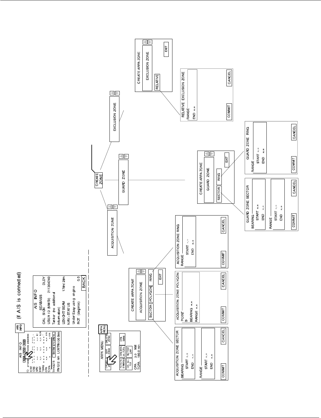
2.4.5 CREATE ZONE form 2−74. . . . . . . . . . . . . . . . . . . . . . . . . . . . . . . . . . . . . . . . . . . . . . . . . . . . .
2.4.5.1 Select ACQUISITION zone form 2−76. . . . . . . . . . . . . . . . . . . . . . . . . . . . . . . . . . . . . . . . .
2.4.5.2 Select GUARD zone form 2−82. . . . . . . . . . . . . . . . . . . . . . . . . . . . . . . . . . . . . . . . . . . . . . .
2.4.5.3 Select EXCLUSION zone form 2−86. . . . . . . . . . . . . . . . . . . . . . . . . . . . . . . . . . . . . . . . . . .
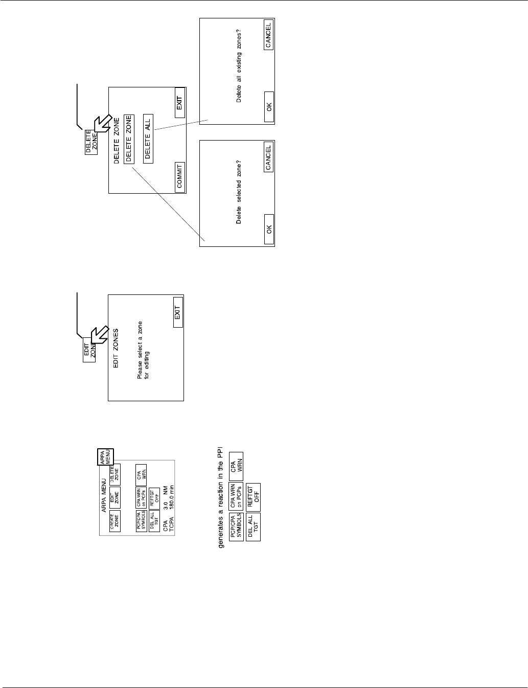
2.4.6 EDIT ZONE 2−88. . . . . . . . . . . . . . . . . . . . . . . . . . . . . . . . . . . . . . . . . . . . . . . . . . . . . . . . . . . . .
2.4.7 DELETE ZONE 2−89. . . . . . . . . . . . . . . . . . . . . . . . . . . . . . . . . . . . . . . . . . . . . . . . . . . . . . . . .
2.4.8 Potential collision points (PCP) and closest point of approach (CPA) symbols 2−90. . .
2.4.9 Closest point of approach (CPA) warning on PCPs 2−94. . . . . . . . . . . . . . . . . . . . . . . . . .
2.4.10 Closest point of approach CPA warning 2−96. . . . . . . . . . . . . . . . . . . . . . . . . . . . . . . . . . . .
2.4.11 Delete all targets 2−97. . . . . . . . . . . . . . . . . . . . . . . . . . . . . . . . . . . . . . . . . . . . . . . . . . . . . . . .

Operator Manual Raytheon Marine GmbH
Germany
R
NSC 18
RADAR
Table of Contents
III 3748DOC020102Edition: 14.JAN.2005
2.4.12 Reference target ON/OFF 2−98. . . . . . . . . . . . . . . . . . . . . . . . . . . . . . . . . . . . . . . . . . . . . . . .
2.4.13 ARPA INFO 2−100. . . . . . . . . . . . . . . . . . . . . . . . . . . . . . . . . . . . . . . . . . . . . . . . . . . . . . . . . . . . .
2.4.14 AIS INFO (option) 2−102. . . . . . . . . . . . . . . . . . . . . . . . . . . . . . . . . . . . . . . . . . . . . . . . . . . . . . .
2.4.14.1 AIS Symbols in the Radar Video 2−104. . . . . . . . . . . . . . . . . . . . . . . . . . . . . . . . . . . . . . . . .
2.4.14.2 AIS symbols 2−105. . . . . . . . . . . . . . . . . . . . . . . . . . . . . . . . . . . . . . . . . . . . . . . . . . . . . . . . . . .
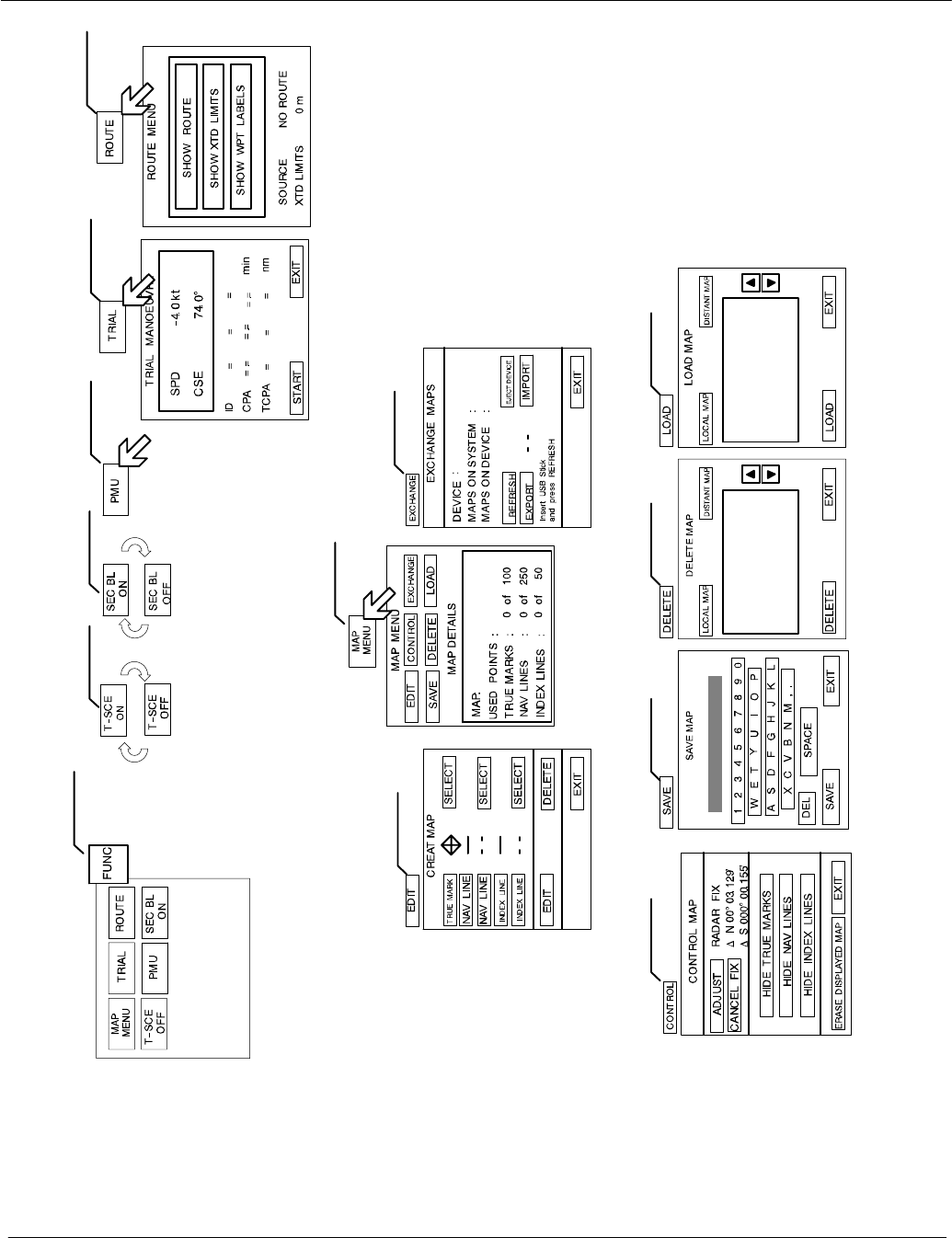
2.5 FUNCTION MENU 2−106. . . . . . . . . . . . . . . . . . . . . . . . . . . . . . . . . . . . . . . . . . . . . . . . . . . . . . . .
2.5.1 Select MAP MENU 2−106. . . . . . . . . . . . . . . . . . . . . . . . . . . . . . . . . . . . . . . . . . . . . . . . . . . . . .
2.5.1.1 MAP MENU − EDIT 2−107. . . . . . . . . . . . . . . . . . . . . . . . . . . . . . . . . . . . . . . . . . . . . . . . . . . . .
2.5.1.2 MAP MENU − CONTROL −2−116. . . . . . . . . . . . . . . . . . . . . . . . . . . . . . . . . . . . . . . . . . . . . .
2.5.1.3 MAP MENU − EXCHANGE −2−120. . . . . . . . . . . . . . . . . . . . . . . . . . . . . . . . . . . . . . . . . . . .
2.5.1.4 MAP MENU − SAVE −2−122. . . . . . . . . . . . . . . . . . . . . . . . . . . . . . . . . . . . . . . . . . . . . . . . . .
2.5.1.5 MAP MENU − DELETE −2−123. . . . . . . . . . . . . . . . . . . . . . . . . . . . . . . . . . . . . . . . . . . . . . . .
2.5.1.6 MAP MENU − LOAD −2−124. . . . . . . . . . . . . . . . . . . . . . . . . . . . . . . . . . . . . . . . . . . . . . . . . .
2.5.2 Select TRIAL MANOEUVRE 2−126. . . . . . . . . . . . . . . . . . . . . . . . . . . . . . . . . . . . . . . . . . . . . .
2.5.3 Select ROUTE (option) 2−130. . . . . . . . . . . . . . . . . . . . . . . . . . . . . . . . . . . . . . . . . . . . . . . . . . .
2.5.4 Select T−SCE (ON/OFF) 2−132. . . . . . . . . . . . . . . . . . . . . . . . . . . . . . . . . . . . . . . . . . . . . . . . .
2.5.5 Select PERFORMANCE MONITOR 2−134. . . . . . . . . . . . . . . . . . . . . . . . . . . . . . . . . . . . . . .
2.5.5.1 Performance monitor 2−134. . . . . . . . . . . . . . . . . . . . . . . . . . . . . . . . . . . . . . . . . . . . . . . . . . .
2.5.6 Select SECTOR BLANKING (ON/OFF) 2−137. . . . . . . . . . . . . . . . . . . . . . . . . . . . . . . . . . . . .
3 Theory of Operation 3−1. . . . . . . . . . . . . . . . . . . . . . . . . . . . . . . . . . . . . . . . . . . . . . . . . . . . . .
3.1 Radar Plotting Terminology 3−1. . . . . . . . . . . . . . . . . . . . . . . . . . . . . . . . . . . . . . . . . . . . . . . .
3.2 Radar Pattern Interpretation 3−5. . . . . . . . . . . . . . . . . . . . . . . . . . . . . . . . . . . . . . . . . . . . . . .
3.2.1 Range 3−5. . . . . . . . . . . . . . . . . . . . . . . . . . . . . . . . . . . . . . . . . . . . . . . . . . . . . . . . . . . . . . . . .
3.2.1.1 Radar Interference 3−6. . . . . . . . . . . . . . . . . . . . . . . . . . . . . . . . . . . . . . . . . . . . . . . . . . . . .
3.2.1.2 Sea Clutter, Rain Clutter 3−7. . . . . . . . . . . . . . . . . . . . . . . . . . . . . . . . . . . . . . . . . . . . . . . . .
3.2.1.3 Side Lobe Effect 3−8. . . . . . . . . . . . . . . . . . . . . . . . . . . . . . . . . . . . . . . . . . . . . . . . . . . . . . .
3.2.1.4 Second trace false echo 3−9. . . . . . . . . . . . . . . . . . . . . . . . . . . . . . . . . . . . . . . . . . . . . . . . .
3.2.1.5 Abnormal Atmospheric Conditions 3−11. . . . . . . . . . . . . . . . . . . . . . . . . . . . . . . . . . . . . . . .
3.3 Vector Presentation 3−12. . . . . . . . . . . . . . . . . . . . . . . . . . . . . . . . . . . . . . . . . . . . . . . . . . . . . . .
3.3.1 True Vector Mode 3−12. . . . . . . . . . . . . . . . . . . . . . . . . . . . . . . . . . . . . . . . . . . . . . . . . . . . . . .
3.3.2 Relative Vector Mode 3−13. . . . . . . . . . . . . . . . . . . . . . . . . . . . . . . . . . . . . . . . . . . . . . . . . . . .

Operator Manual
Table of Contents
IV
3748DOC020102 Edition: 14.JAN.2005
3.4 Automatic Radar Plotting Aid (ARPA) 3−14. . . . . . . . . . . . . . . . . . . . . . . . . . . . . . . . . . . . . . .
3.4.1 Sensor Errors 3−15. . . . . . . . . . . . . . . . . . . . . . . . . . . . . . . . . . . . . . . . . . . . . . . . . . . . . . . . . . .
3.4.1.1 Gyro Compass 3−15. . . . . . . . . . . . . . . . . . . . . . . . . . . . . . . . . . . . . . . . . . . . . . . . . . . . . . . . .
3.4.1.2 Speed Log 3−15. . . . . . . . . . . . . . . . . . . . . . . . . . . . . . . . . . . . . . . . . . . . . . . . . . . . . . . . . . . .
3.4.1.3 Plotting 3−16. . . . . . . . . . . . . . . . . . . . . . . . . . . . . . . . . . . . . . . . . . . . . . . . . . . . . . . . . . . . . . .
3.4.2 Collisions Assessment (Surveillance) 3−18. . . . . . . . . . . . . . . . . . . . . . . . . . . . . . . . . . . . . .
3.4.2.1 Accuracy of Collision Assessment 3−18. . . . . . . . . . . . . . . . . . . . . . . . . . . . . . . . . . . . . . . .
3.4.2.2 Displaying of CPAs 3−18. . . . . . . . . . . . . . . . . . . . . . . . . . . . . . . . . . . . . . . . . . . . . . . . . . . . .
3.5 Keep the following points in mind when operating the NSC. 3−20. . . . . . . . . . . . . . . . . . . .
Annex

NSC
List of Abbreviations
A
ACP, Azimuth Commit Point
ARPA, Automatic Plotting Aid
ARP, Azimuth Reset Point
B
BRG, Bearing
C
CPA, Closest Point of Appoach
C−UP, Course Up
CSE, Course
CURS, Cursor
D
DST, Distance
E
EBL, Electronic Bearing Line
ETA, Estimated Time of Arrival
EXCL, Exclusion
EXP, Expansion
F
F, Floating
FTC, Fast Time Constant
FTM, Fix True Motion
H
H−UP, Head Up
HDG, Heading
HW, Hardware
I
ISU, Interswitch Unit
L
LP, Long Pulse
M
MTR, Modulator Transmitter Receiver
N
N−UP, North−Up
NM, Nautical Miles
P
PCP, Potential Collision Point
PMU, Performance Monitor Unit
POS, Position
PPI, Plan Position Indicator
R
RACON, Receiver/Transmitter Trans-
ponder Devices used as a Navigation
aid
R−UP, Repeater Up
RCSE, Relative course
RM (R), Relative Motion and Relative
Trails
RM (T), Relative Motion and True Trails
RNG, Range
RR, Range Rings
RSPD, Relative Speed
S
STBY, Standby
SHM, Ship Heading Marker
SP, Short Pulse

NSC
List of Abbreviations
T
T−SCE, Test scenario
TCM, Transceiver control module,
TN, Tune
TTG, Time to go
Tx, Transceiver ON
TCPA, Time of Closest Point of Approach
TM, True Motion
TRU, True
TTG, Time To Go
TFT, Thin Film Transistor
V
VRM, Variable Range Marker
X
XCVR, Transceiver unit
Operator Manual Raytheon Marine GmbH
Germany
R
NSC 18
RADAR
3748DOC020102Edition: 03.JAN.2005
QUICK STARTUP GUIDE
STDBY/TX NUP
MODE RM (T)
TRAILS TRUE
SPEED LOG (WT)
VECTOR TRUE
FILTER (KEY) ON
ECHO EXP ON
ANTI−COLLISION AREAS
ARPA PCP/CPA, CPA WRN on
PCPs
FWD ARPA CUP
OPTIONAL
VECTOR REL
PLOT HISTORY RM (R)
TRAILS REL
RECOMMENDED
USER ADJUSTMENTS AFTER
SWITCHING ON THE NSC RADAR
Trackball
Cursor
SHORT OPERATION Raytheon Marine GmbH
Germany
R
NSC
3748DOC02012Edition: 03.JAN.2005
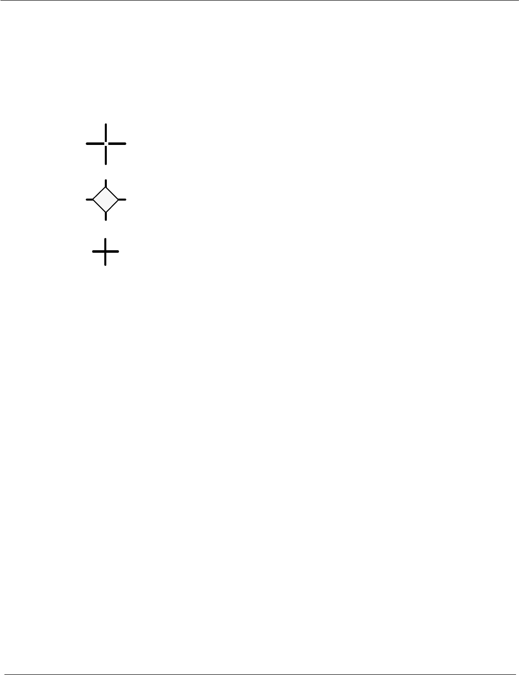
CURSOR SYMBOLS
NORMAL CURSOR outside the PPI
DEFAULT CURSOR
OFFSET CURSOR
ECDIS CURSOR (option see chapter 2.2.2.2)
Select the PPI−presentation in favor.
means Relative Motion, own ship is stationary and other
objects, including land masses boys, ships at anchor and
ships in motion, move with correct relative speed and course
means True Motion, land masses, bouys, ships at anchor,
etc. appear exactly as they are. Objects in motion, including
own ship, move with correct true speed and course across
the operating screen.
means North−Up, geographic north is upward
−Stabilized operation−. GYRO Compass information is
required for North−Up operation.
means Head−Up, heading is upwards
−Unstabilized operation*−.
means Course−Up, course is upwards
−Stabilized operation−. GYRO Compass information is
required for Course−Up operation.
means Reapter−Up, repeater indication is upwards
−Unstabilized operation−.
3.
Day or Night mode
Press this button if you want to change in the night
mode.
T
T
T
T
T
2.
Switch ON the NSC.
Press the button 5s, the main power has to be switched on.
The Run−Up phase is terminated after 190s.
The NSC status is STANDBY.
Select this softkey per cursor. The softbutton name changes
to TX. The radar is ready for operation.
The attitudes selected last are effective:
These are:
PPI presentations and adjustments, Antenna sensitivities,
last Sensor choice.
1.
SWITCH ON THE RADAR,
SELECT THE BEST PRESETTINGS
Check
Dthe ALARM−Messages (detailed information
see chapter 2.3.6.4).
Dthe position indication between radar information
panel and position sensor.
Dthe radar video with the real area, make a bearing
to a known target (bouy, beacon, church).
Dthe magnetron quality. Check it with the performance
monitor (see chapter 2.5.5).
PPI adjustments
Select your required Range Scale (highest value
96.0 NM, lowest value 0.125 NM).
Fade the Range Rings, Rings are used to make quick
assessment of target’s approximate range from own ship.
The ship symbole appears in the range scale between
0.125 NM to 96.0 NM or in the ring scale
0.02 NM to 16 NM.
SITUATION SETTINGS
Antenna Sensitivity controls
AUTO mode for TUNE.
The TUNE control is used to tune the Receiver
Frequency to match that of the Transmitter.
The tune adjustment should be made on the
medium or long range scales that show radar returns.
The GAIN control adjusts the sensitivity of the radar
display.
AUTO mode for SEA, RAIN, FTC (SFAR).
The SEA control is used to suppress radar returns which
are the result of radar signals reflected from waves.
The RAIN control is used to suppress radar returns
which are the result of radar signals reflected from rain
drops.
FTC performs differentiating, or filtering of rain clouds.
Search and rescue transponder SART ON is to improve
detection of SART.
Select the puls length, from short to long pulse and vice
versa to optimize the target discrimination with respect
to selected range.
Select the interference function (ON or OFF).
Select the echo expansion (ON or OFF).
SHM
see chapter 2.3.2.1
Cursor
information
in the radar video
range,
see chapter 2.3.5
Antenna
sensitivity
controls
see chapter 2.3.1
Navigation
Electronic bearing lines (EBL) and variable
range markers (VRM)
see chapter 2.3.4
Park position
automatic cursor position
MenuBar
see chapter
2.3.6.6
Information
panel
see chapter 2.3.6
Radar Video
settings
see chapter 2.3.3
Radar Video
displays
see chapter 2.3.2
Radar operator panel
see chapter 2.2.3
used as SET button
Trackball
*) Unstabilized operation means.
No heading− or speed−sensor was available.
In this case following NSC functions are not possible:
ARPA function, True Motion, Fast Target ON/OFF
Afterglow Trail
Trackball
see
chapter 2.2.2
North
Marker
used to pick−up for
picking−up and
dragging something
Operator Manual Raytheon Marine GmbH
Germany
R
NSC 18
RADAR
1−13748DOC020102Edition: 14.JAN.2005
IMPORTANT NOTICE AND SAFETY INFORMATIONS
This Radar is an aid to navigation. Its accuracy can be affected by
many factors such as equipment defect, environmental conditions, or
improper operation. It is the user’s responsibility to exercise common
prudence and navigational judgement at all times.
This equipment has been tested and found to comply with the limits
for a Class A digital device, pursuant IEC 60936 to IEC 60872, IEC
60945.
These limits are designed to provide reasonable protection against
harmful interference when the equipment is operated in a commercial
environment.
This equipment generates, uses and can radiate radio frequency en-
ergy and, not installed and used in accordance with the instructions,
may cause harmful interference to radio communications. Operation
of this equipment in a residential area is likely to cause harmful inter-
ference in which case the user will be required to correct the.
interference at his own expense.
ATTENTION
Operator Manual
1−2
3748DOC020102 Edition: 14.JAN.2005
There is absolutely no danger in handling the external controls of the radar
while the radar is in operation. In the radar‘s interior, however, are high
voltages which are fatally dangerous to anyone careless handling interior
components. Be absoluteley sure that the radar power switch is OFF before
performing repair work or maintenance .
Furthermore, even when the power switch is turned off, a high voltage remains
in certain parts of the radar circuits. In particular, be careful of the magnetron
heater circuit, cathode−ray tube anode circuit, etc.. Utilizing a length of wire
with one end fully grounded or an insulated srewdriver, ground all high voltage
sections to discharge the residual charges and ensure that no charges remain
before touching any part of the high voltage sections. In any case, the most
dangerous thing to do is to touch any part of the high voltage sections without
making sure that the radar power switch is off.
HIGH VOLTAGE
Exercise care when approaching a rotating antenna. Be sure to turn off the
radar power switch before performing maintenance or inspection of the
antenna. Also, make sure that nothing or no one is near the antenna when
turning on the radar power supply.
ATTENTION

Operator Manual Raytheon Marine GmbH
Germany
R
NSC 18
RADAR
1−33748DOC020102Edition: 14.JAN.2005
A short exposure to the microwaves radiated by the radar antenna is harmless.
However, avoid prolonged exposure to the microwaves. Never look directly into the wave
guide while checking transceiver operation, since microwaves are especially harmful to the
eyes.
The radiation of microwaves can be checked with a neon tubel . The neon tube will glow in
the presence of microwaves.
MICROWAVE RADIATION

Operator Manual
1−4
3748DOC020102 Edition: 14.JAN.2005
1 Introduction
The Operator Manual
An operator should become familiar with the location of the display information
and the control panel buttons.
Manual overview.
Glossary of Terms
chapter 1 for important safety notes
for showing the NSC Radar System
chapter 2 for operation
short operation
chapter 3 for theory of operation
The NSC Radar is designed in accordance with the rules of the International
Maritime Organization IMO*.
* The International Maritime Organization is the specialized agency of the
United Nations with responsibility for safety and security at sea and the
prevention of marine pollution from ships.
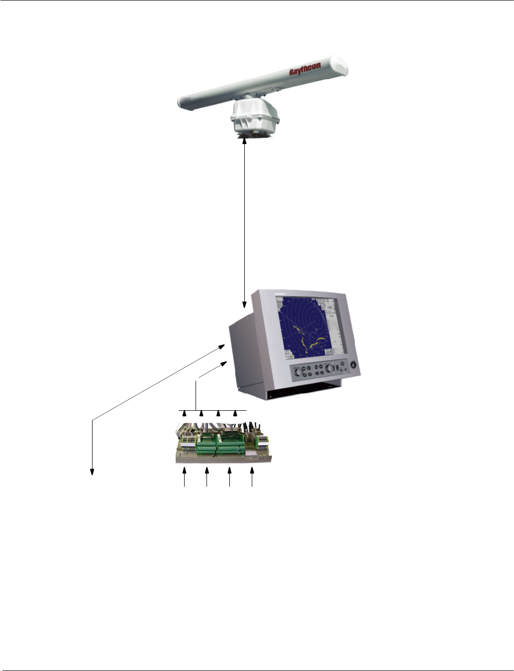
The main components of the NSC Radar system include (see Figure: 1):
−the Flat Screen Display (TFT Technology)
−the Track ball, or alternatively the Radar Operator Panel to operate the Radar
−the Radar Processor which is, in addition to the NSC software, the interface to
the radar antennas (X/S−Band) and peripheral equipment (Gyro Compass,
GPS, Log Sensor, AIS, SART).
The operating surface of the NSC Radar:
The NSC Radar can be completely operated via the trackball−controlled cursor.
The Radar Operator Panel is designed for the execution of certain NSC func-
tions.
Operator Manual Raytheon Marine GmbH
Germany
R
NSC 18
RADAR
1−53748DOC020102Edition: 14.JAN.2005
1.1 Radar System
Figure: 1 NSC Radar System
Option: Can Bus Power 24V DC
Gyro−Interface
for Sperry/Synchro
Step Input
NSC
connection
board
possible signal inputs
(NMEA I/O):
Gyro/Speed Sensors,
AIS
10 kW X−band
antenna unit
(6 feet array)
NSC 18 Radar Display
Operator Manual Raytheon Marine GmbH
Germany
R
NSC 18
RADAR
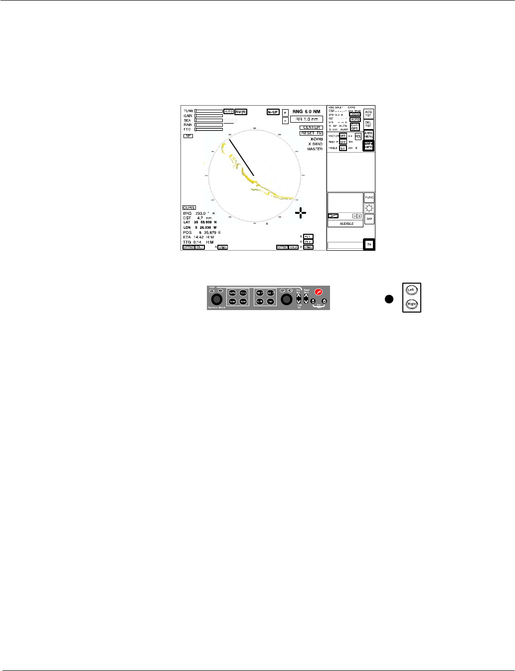
2−13748DOC020102Edition: 14.JAN.2005
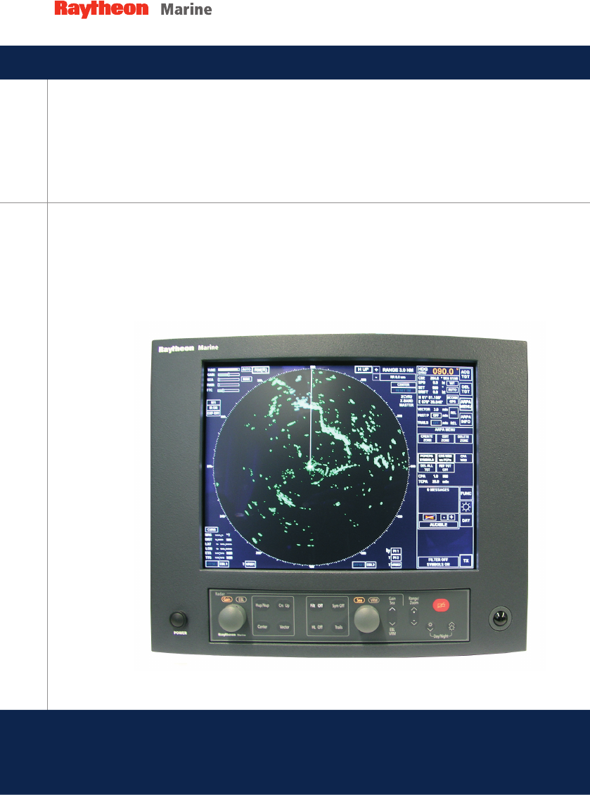
2 OPERATING INSTRUCTIONS
Three components are essential for operation of the NSC 18
Figure: 2−1 NSC Radar components for operation
Display
Radar control panel Trackball
Display
The display is a high−resolution TFT (Thin Film Transistor) flat screen color
monitor. It shows radar targets and data as well as a number of menus and
software buttons.
Trackball
All radar functions can be operated by trackball.
Radar control panel
A range of important functions can also be operated using the radar
control panel.
Operator Manual
2−2
3748DOC020102 Edition: 14.JAN.2005
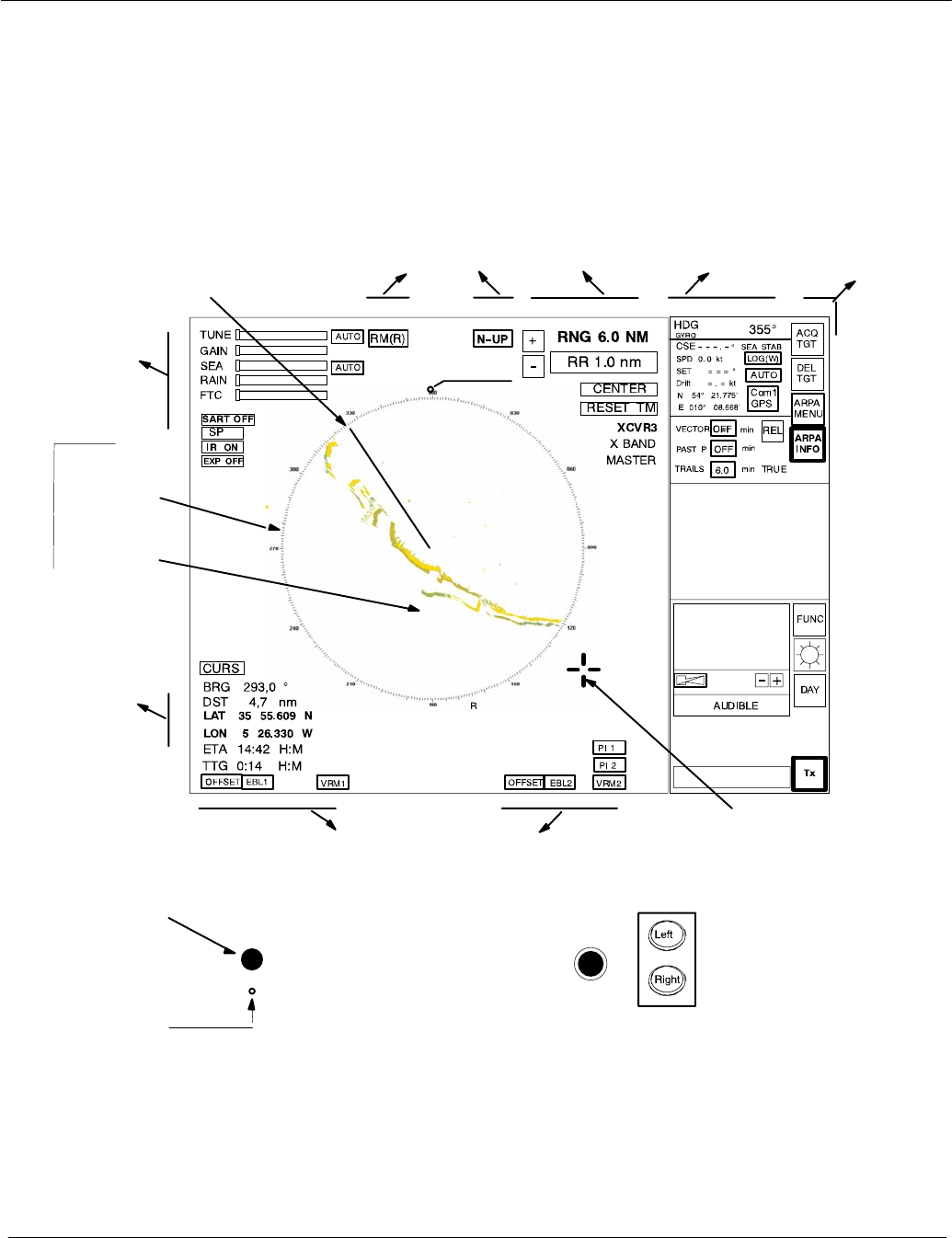
2.1 DISPLAY ORGANIZATION AND SUBMENU STRUCTURE
The following figures provide an overview of the organization of the NSC display
and its submenu structure.
Trackball
see
chapter 2.2.2
Cursor information
in radar video range,
see chapter
2.3.5
Antenna
sensitivity controls,
see chapter 2.3.1.
Navigation
Electronic bearing lines (EBL) and variable range
markers (VRM), see chapter 2.3.4
Radar video
settings,
see chapter 2.3.3
Radar video
displays,
see chapter 2.3.2
INFORMATION
PANEL,
see chapter 2.3.6 MENU
bar,
see
chapter
2.3.6.6
Park position
automatic cursor
position
SHM
see chapter 2.3.2.1
Radar
compass rose
with NORTH
MARKER
Radar video
Figure: 2−2 Display organization
Power
ON/OFF
button
see chapter
2.2.1
PPI
Reset
Dip switch
see chapter
2.2.5
T
T
T
T
T
North
Marker
Operator Manual Raytheon Marine GmbH
Germany
R
NSC 18
RADAR
2−33748DOC020102Edition: 14.JAN.2005
Figure: 2−3 Display and submenu organization
Operator Manual
2−4
3748DOC020102 Edition: 14.JAN.2005
Figure: 2−4 Display and organization of AIS INFO and ARPA MENUs
Chapter 2.4.5
Chapter ..2.4.14..
Operator Manual Raytheon Marine GmbH
Germany
R
NSC 18
RADAR
2−53748DOC020102Edition: 14.JAN.2005
Figure: 2−5 Display of ARPA submenu and selected functions
Chapter 2.4.6 Chapter 2.4.7
Operator Manual
2−6
3748DOC020102 Edition: 14.JAN.2005
Figure: 2−6 Display of FUNCtion submenu and selected functions
Chapter 2.5.4 Chapter 2.5.5 Chapter 2.5.2
Chapter 2.5.1.1 Chapter 2.5.1.3
Chapter
2.5.1.2
Chapter
2.5.1.4
Chapter
2.5.1.5
Chapter
2.5.1.6
Chapter 2.5 Chapter 2.5.6
Chapter 2.5.1
Chapter 2.5.3

Operator Manual Raytheon Marine GmbH
Germany
R
NSC 18
RADAR
2−73748DOC020102Edition: 14.JAN.2005
2.2 FIRST STEPS IN OPERATION
This chapter describes following basic functions
DSwitching ON the NSC radar system, STANDBY mode,
synchronization setting of the heading signal (see chapter 2.2.1)
DHow to use the CURSOR (see chapter 2.2.2)
DHow to handle the RADAR OPERATOR PANEL (see chapter 2.2.3)
DOperator controls in the NSC display (see chapter 2.2.4)
DSystem reset (see chapter 2.2.5)
DSwitching OFF the NSC radar system (see chapter 2.2.6)
Power button
RADAR
Operator Manual
2−8
3748DOC020102 Edition: 14.JAN.2005
2.2.1 Switching ON
Positioned on front, lower left side.
Pressing the button switches on the power.
DThe Radar Utility Selector window appears in the display.
Select the RADAR softkey in the window and press the Left
button on the trackball.
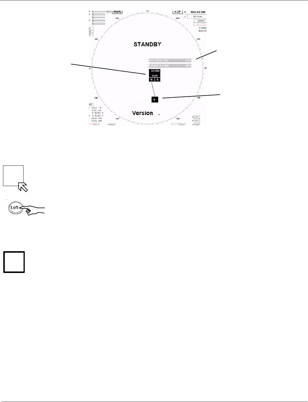
DAfter about 40 seconds, the message STANDBY appears in the image
center.
DThe system configuration diagram is shown in the center of the display
area (see Figure: 2−7).
Select the desired transceiver combination XCVR ..... and the
master/slave assignment if possible (system specific).
The STANDBY message changes to WARM UP.
DAfter a few minutes the warm up period is
complete and the WARM UP message changes back to STANDBY.
DNSC Radar is in STANDBY mode.
The NSC beeps when
the NSC radar software detects an internal or external malfunction;
a simultaneous alarm message is displayed.
Acknowledging the alarm message switches off the acoustic signal. The
alarm message is hidden, but it can be called up again.
NSC status:
The transceiver is not transmitting.
The antenna is not rotating.
No radar video in PPI, STANDBY.
Service and setup menu accessible.
The operating temperature is maintained by the magnetron.
STBY
Tx
Operator Manual Raytheon Marine GmbH
Germany
R
NSC 18
RADAR
2−93748DOC020102Edition: 14.JAN.2005
Figure: 2−7 NSC Radar in STANDBY mode −System configuration diagram
−
Operating hours
counter
Radar display as-
signment
Modulator
transmitter−
receiver
(XCVR...)
assignment
. . .
Switching the radar ON
Using the trackball, place the cursor on the STBY softkey and press the Left
button on the trackball.
The name of the softkey changes to Tx and is highlighted.
After 1..2 scans the radar video is displayed in the PPI area.
All settings for optimization of the system can be made by using the toggle fields
and softkeys that are constantly available.
Left
Left
Right
Operator Manual
2−10
3748DOC020102 Edition: 14.JAN.2005
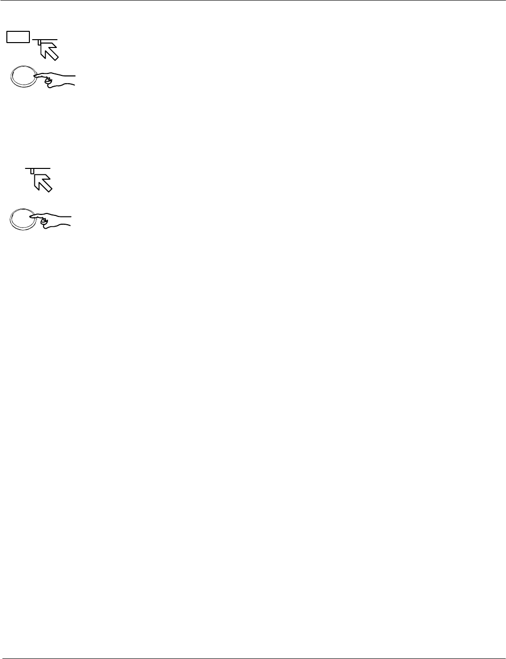
2.2.2 How to use the CURSOR
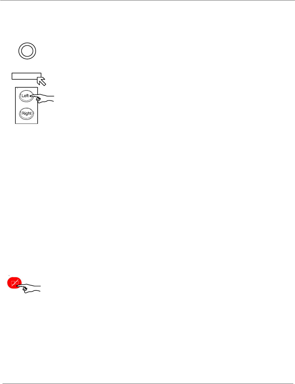
When using the trackball, the cursor is moved by rolling the ball in the
appropriate direction.
The trackball−guided cursor is the central control for using this radar.
Figure: 2−8 Trackball
The trackball is equipped with two buttons.
This button is used as the Left button.
This means:
−Using the trackball, place the cursor over a softkey from the menu bar and
press the button. The softkey function is activated (see chapter 2.2.4.1).
−Using the trackball, place the cursor over a text line (e.g. SET, DRIFT) or a
toggle field with slider function. Press and hold the upper button and move
the trackball.
The slider below the text line or toggle field is moved horizontally,
and a value is displayed (see chapter 2.2.4.4).
Press Left button again to store the value.
−Using the trackball, place the cursor over a slider, e.g. GAIN, press and
hold the Left button and move the trackball. The slider will follow the
trackball to the left or the right.
This button is used for Pick up and drag operations.
This means:
Normally used in the radar video to pick up a symbol e.g. EBL/VRM and
drag the symbol to a new position within the radar video using the trackball.
Press the Left button to set up the symbol.

Operator Manual Raytheon Marine GmbH
Germany
R
NSC 18
RADAR
2−11 3748DOC020102Edition: 14.JAN.2005
2.2.2.1 Cursor in park position
This function is selectable.
Select the CURS button, the CURSOR READOUT displays in the function
display.
MOUSE PARK POSITION ON means;
If you do not use the cursor for some time, it jumps automatically into park
position outside the radar video area, see Figure: 2−14.
Move the trackball and you will see the cursor again.
MOUSE PARK POSITION OFF means;
No park position function.
Operator Manual
2−12
3748DOC020102 Edition: 14.JAN.2005
2.2.2.2 Cursor symbols
Figure: 2−9 Cursors illustrate the various cursor symbols that will be seen when
using the NSC display.
Figure: 2−9 Cursor symbols
DEFAULT CURSOR
OFFSET CURSOR
second cursor symbol (in red) appears in the radar video if
the NSC Radar and the NSC ECDIS are
combined as a system
Operator Manual Raytheon Marine GmbH
Germany
R
NSC 18
RADAR
2−13 3748DOC020102Edition: 14.JAN.2005
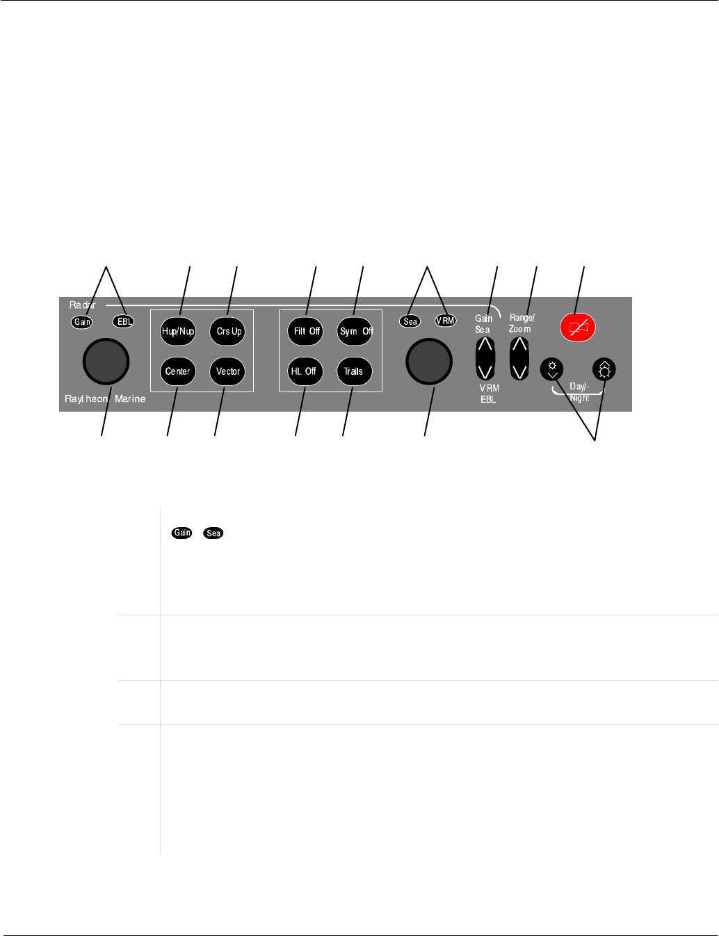
2.2.3 Radar operator panel
The radar operator panel is designed to execute the most commonly
used functions.
Signaling:
Illumination of the buttons and status indicators is switched on when the relevant
action is activated.
Figure: 2−10 Radar operator panel
123456789
16 15 14 13 12 11 10
1/6Status indicators, press toggle switch (7). The function activated is indicated by
( ). Use the dial (16) to adjust the Gain. Use the dial (11) to adjust the
Sea. The Gain control adjusts the sensitivity of the radar video.
The Sea control is used to suppress radar returns which are the result of radar
signals reflected from waves.
2Radar Video displays, press button to use Head up or North up.
Head up means the ship’s bow is upwards.
North up means geographic north is upwards.
3Radar Video display, press button to use Course up.
Course up means the course is upwards.
4Anti−clutter filter ON/OFF, press the button.
In case of heavy clutter developing on the Radar Video, the NSC computer
creates a profile of the echo. Within this profile, the received echoes are
monitored for a certain period (Scan−to−scan method). Irregular echoes are
suppressed on the Radar Video. Regular echoes are indicated on the Radar
Video.

Operator Manual
2−14
3748DOC020102 Edition: 14.JAN.2005
5Hides the symbols in the radar video.
Press the button and the artificial symbols will disappear. Press again to show
the symbols.
Symbols are EBLs, VRMs, PL, ARPA zones, MAPs.
6/1Status indicators, press toggle switch (7). The activated function is indicated by
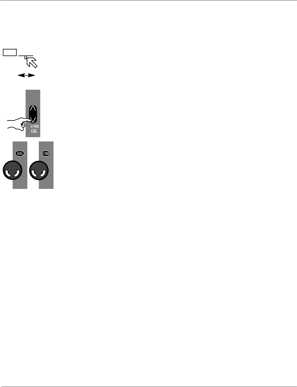
( ). Use the dial (11) to adjust EBL. Use the dial (16) to adjust VRM.
7Toggle switch. Can be switched between upper position, Gain / Sea and lower
position, VRM / EBL. See status indicators (1/6) and use dial (16) or dial (11).
8Toggle switch. Range selection, switches the radar ranges up and down.
9Alarm indicator (flashing) and alarm acknowledgment.
10 Dimmer buttons for button illumination and radar display backlight.
Press both buttons to switch between Day/Night mode.
11 Dial, see 6/1.
12 Press button in steps, the Trails indicator changes to the next higher mode.
The steps available are OFF, 1.0, 3.0, 6.0, OFF, see TRAILS toggle field in infor-
mation panel.
13 Press and hold the button. The Heading Line disappears during this time.
14 Press button to use to change VECTOR LENGTH.
15 Center to reset your own ship to the middle of the PPI or to activate OFF CEN-
TER
16 Dial, see 1/6.
Table:1 Radar operator panel − Function overview −
ACQ
TGT
DEL
TGT
ARPA
MENU
ARPA
INFO
AIS
INFO
FUNC
SERV
Operator Manual Raytheon Marine GmbH
Germany
R
NSC 18
RADAR
2−15 3748DOC020102Edition: 14.JAN.2005
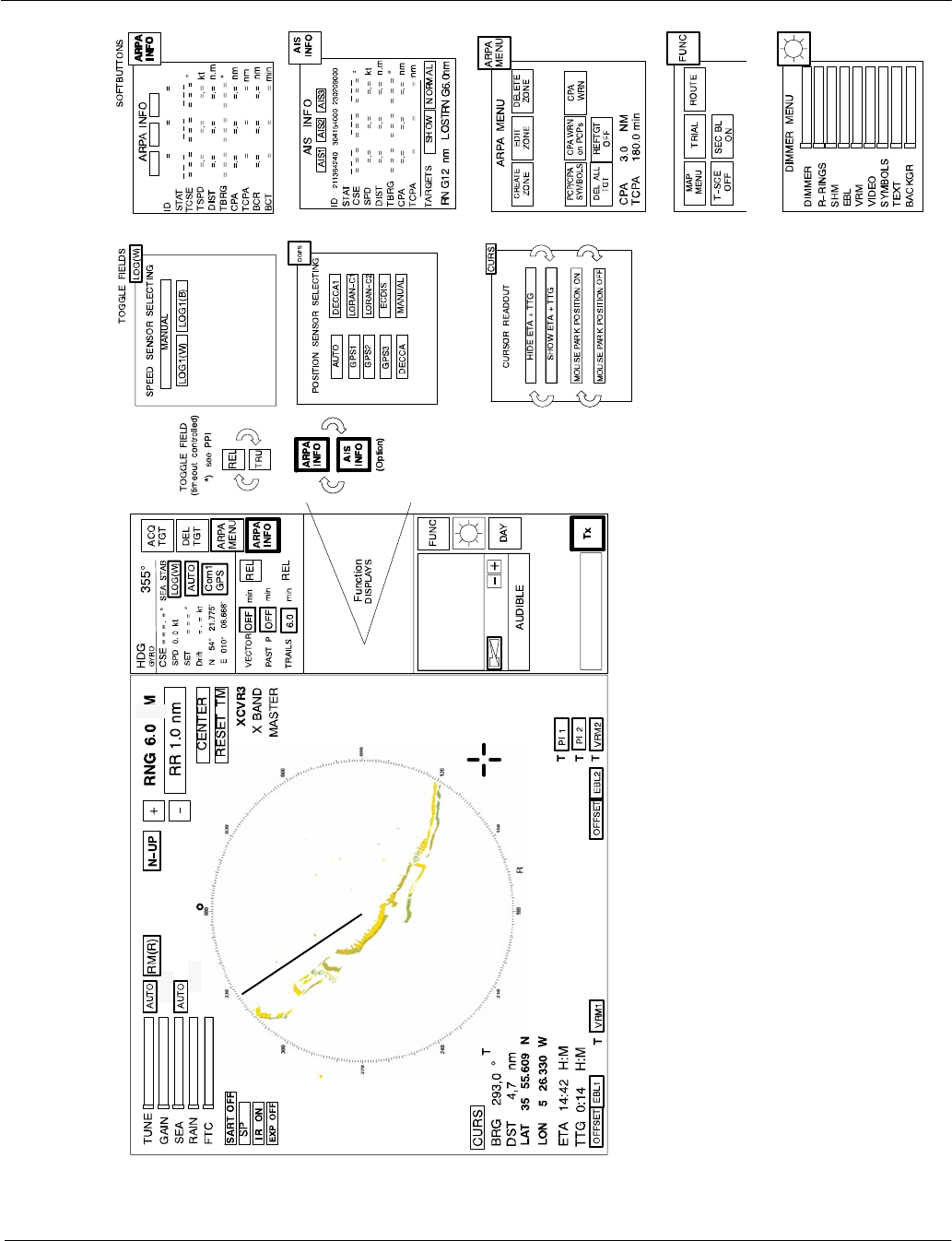
2.2.4 Softkeys and operator controls in NSC display
2.2.4.1 Softkeys in menu bar
The text on the softkeys always describes the current mode status.
Example:
DAY means that the radar is in DAY mode
STBY means that the radar is in Standby mode
Clicking on the software button changes the status.
A selected softkey is distinguished from a non−selected softkey by its lighter
contours.
Softkeys in action
DThis softkey function allows manual acquisition of visible targets within the
radar video (see chapter 2.4.2).
DThis softkey function allows individual, acquired targets to be cancelled,
except for those which have transmitted a collision alarm.
DFor the CREATE ZONE, EDIT ZONE, DELETE ZONE,
SAVE EXCL ZONE, LOAD ZONE functions (see chapter 2.4).
DFor the current ARPA tracking information.
DFor the current AIS information (option).
DFor additional radar video functions e.g. MAP MENU.
The Maps function allows the operator to create and permanently store maps
(see chapter 2.5).
DUsing the NSC in the STANDBY mode the softkey function FUNC changes to
SERV (service mode). The service mode is used to configure your radar
system.
DAY
NIGHT
EXIT
RADAR
Tx
STBY
Operator Manual
2−16
3748DOC020102 Edition: 14.JAN.2005
DTo find the optimum brightness for the visual features of the PPI and for the
visual features located around the PPI (see chapter 2.3.6.6).
DThis softkey function allows you to choose whether the NSC operates in DAY
mode or in NIGHT mode (see chapter 2.3.6.6).
DThis softkey function allows you to exit the NSC RADAR completely (see
chapter 2.2.6).
DThis softkey function allows you to choose between NSC in STANDBY or
TRANSCEIVER ON (see chapter 2.3.6.6).
Operator Manual Raytheon Marine GmbH
Germany
R
NSC 18
RADAR
2−17 3748DOC020102Edition: 14.JAN.2005
2.2.4.2 Operator controls in NSC display
To handle this NSC display, you need to use certain built−in operator controls.
These operator controls are as follows:
Softkey
Toggle fields
Toggle field with slider
(numerical and static indicator)
Text line with slider
(numerical indicator)
Slider
Operator controls Text identifier
Figure: 2−11 Operator controls in NSC display
All these controls can be selected using the trackball−guided cursor and the
trackball Left button.
or
+
−
GAIN
Slider
and
Press
and
hold
Tuning
bar
Left
GAIN
Slider
and
Press
Left
Operator Manual
2−18
3748DOC020102 Edition: 14.JAN.2005
2.2.4.3 Toggle fields
The toggle field functionalities are called up by pressing the trackball buttons
or alternatively (partially) using the buttons on the operator panel.
Example:
The range is increased by clicking on the (+) button and decreased using the (−)
button.
2.2.4.4 Sliders
The slider settings can be analog or made in steps.
Analog slider setting
For analog setting, the cursor must be positioned on the slider for the desired
function (e.g. GAIN).
Press and hold the trackball button, move the trackball.
The slider is moved to the right or the left, according to the trackball direction
(see concurrent tuning bar display). The slider setting is transferred to the
radar video immediately.
Steps, slider setting using trackball
For this setting, the cursor must be positioned in the open area of the slider
frame (e.g. GAIN).
Pressing the trackball button moves the slider gradually towards the cursor
position (see concurrent tuning bar display).
The slider setting is transferred to the radar video immediately.
NOTE
Slider settings are individual. Within the NSC technology, these values are
treated as transient values.
Transient values cease to be valid after switching to STBY or switching off
the unit. When the unit is switched on again, the sliders are set to their
default values.
127.9°
and
Press
and
hold
EBL2 R
Left
Left
SET
and
Press
and
hold
12 °
Operator Manual Raytheon Marine GmbH
Germany
R
NSC 18
RADAR
2−19 3748DOC020102Edition: 14.JAN.2005
Toggle field with slider
Position the cursor on the toggle field, press and hold the trackball button.
A slider appears below the toggle field.
The slider can make an analog movement in the desired direction using the
trackball. In parallel, the numerical value above the slider changes.
Releasing the trackball button concludes the setting.
Click the numerical field again to store the selected value.
Text line with slider (used for SET and DRIFT values)
Position the cursor on the text line value field, press and hold the trackball
button. A slider appears below the value field.
The slider can make an analog movement in the desired direction using the
trackball.
In parallel, the numerical value above the slider changes.
Releasing the trackball button concludes the setting.
Click in field again to store the values.
.
Operator Manual
2−20
3748DOC020102 Edition: 14.JAN.2005
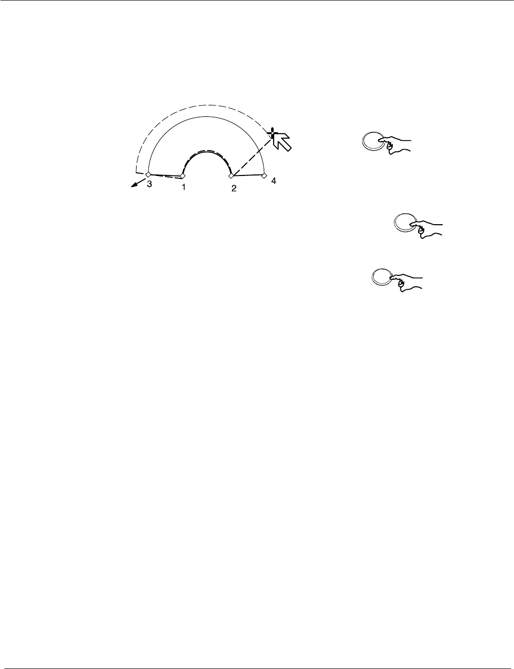
2.2.4.5 Drag and drop
This cursor controlled operation is used in radar video;
e.g. if an acquisition zone is to be changed.
Editing markers
Position the cursor on the zone
Press once
The zone is now shown in a dotted form,
editing markers are shown at the corners.
Position the cursor on the desired marker.
Press and hold
Drag the marker to the desired position
Pick up:
Drop:
Press once
The change is completed, the zone
switches from dotted to continuous form.
Figure: 2−12 Drag and drop
Right
Right
L
ef
t

Peak item
Power ON/OFF
button
Reset
Dip
Switch
Operator Manual Raytheon Marine GmbH
Germany
R
NSC 18
RADAR
2−21 3748DOC020102Edition: 14.JAN.2005
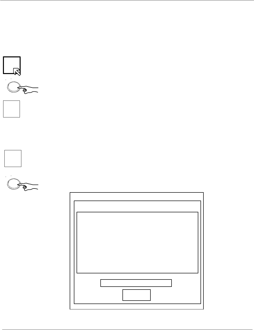
2.2.5 System reset
When a system reset is carried out, only the NSC software is re−initialized; the
transceiver remains actuated.
Procedure:
Trigger the system reset. Press the dipswitch briefly with a pointed object.
The display turns dark briefly and the system is re−initialized.
The NSC display appears with the following basic settings.
After any restart, the NSC display unit makes certain basic settings. These
include
−TUNE in AUTO mode
−GAIN in center position
−SEA in 0 position
−RAIN in 0 position
−FTC in 0 position
−DIMMER in max. position
−Range in 6NM
−Vector at 6.0 min
Tx
Left
STBY
EXIT
RADAR
Left
Operator Manual
2−22
3748DOC020102 Edition: 14.JAN.2005
2.2.6 Switching OFF the NSC radar system
The following procedure should be used to switch off the NSC radar system.
Procedure:
Switching the radar OFF
Using the trackball, place the cursor on the TX softkey and press the
button from the trackball group.
The name of the softkey changes to STBY and is highlighted.
−radar echo disappears
−the antenna stops, no transmission
−the name of the softkey FUNC changes to SERV (Service).
−the softkey EXIT RADAR appears
Pressing this softkey the RADAR Utility selector appears
Select Operator Close System and Power Off in the RADAR Utility selector
window and press the button from the trackball again.
Operator Change Date/Time
Operator Close System and Power Off
Operator Refresh Radar
Service Switch to Admin + password
Service Report Export to USB
Service Raytheon Update from USB memory
Service Display Resolution
Service Display Network
+++ RADAR Utility selector +++
Utility Selections
Run Selection
RADAR
Figure: 2−13 RADAR Utility selector
Operator Change Date/Time
Operator Close System and Power Off
Operator Refresh Radar
Service Switch to Admin + password
Service Report Export to USB
Service Raytheon Update from USB memory
Service Display Resolution
Service Display Network
+++ RADAR Utility selector +++
Utility Selections
Run Selection
RADAR

Power button
Operator Manual Raytheon Marine GmbH
Germany
R
NSC 18
RADAR
2−23 3748DOC020102Edition: 14.JAN.2005
Press the power button for approx. 4s.
The process is complete.
Operator Manual
2−24
3748DOC020102 Edition: 14.JAN.2005
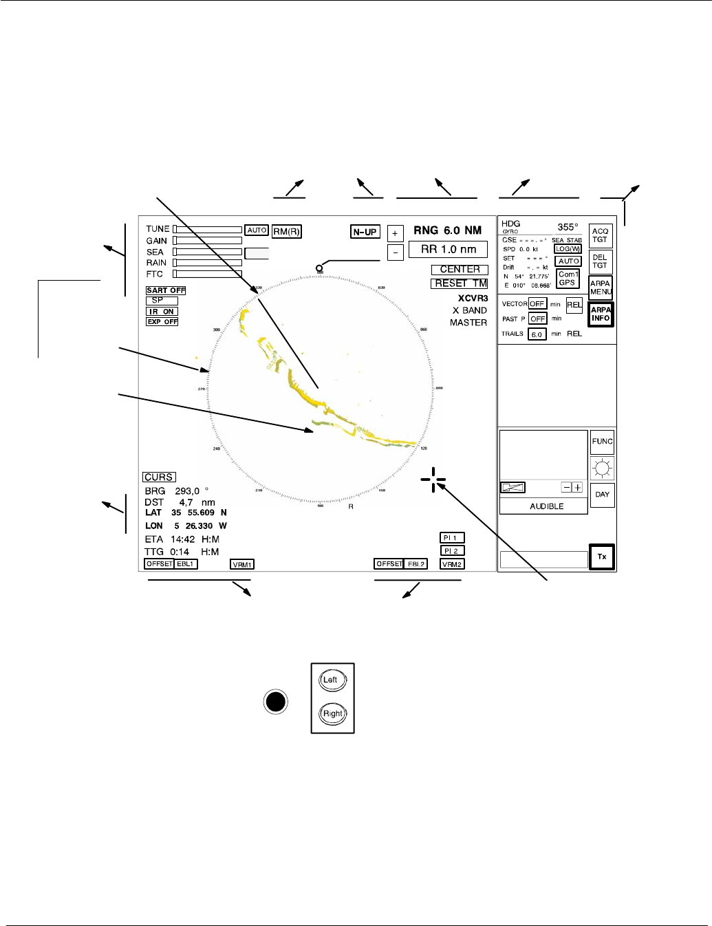
2.3 DISPLAY OPERATIONS AND INDICATORS
This chapter describes the function sections of the NSC display
see Figure: 2−14.
T
T
T
T
T
Figure: 2−14 Display organization
Trackball
see
chapter 2.2.2
Cursor information
in radar video range,
see chapter 2.3.5
Antenna
sensitivity controls,
see chapter 2.3.1.
Navigation
bearing lines and range rings,
see chapter 2.3.4
Radar video
settings,
see chapter 2.3.3
Radar video
displays,
see chapter 2.3.2
INFORMATION
PANEL,
see chapter 2.3.6 MENU
bar,
see
chapter
2.3.6.6
Park position
automatic cursor
position
SHM
see chapter 2.3.2.1
Radar
compass
rose with
NORTH
MARKER
Radar video
PPI North
Marker
Operator Manual Raytheon Marine GmbH
Germany
R
NSC 18
RADAR
2−25 3748DOC020102Edition: 14.JAN.2005
2.3.1 Sensitivity controls
2.3.1.1 Gain and clutter processing
The NSC uses a digital video processing technique called Scan to Scan
integration or field processing. This process requires 3 complete antenna
rotations or scans of the antenna in order to build up or decay detected targets.
To the operator, this means that when a target is first detected, it appears dim.
If, on the next scan, it is still present at the same location, it appears at medium
brightness and on the third scan, it appears at full brightness. As long as the
target is present, it will appear at full brightness.
If the target fades in and out, then it will remain on the screen, dropping from full
brightness to medium and back to full brightness.
If the target is lost altogether, then it will take three scans before it completely
disappears.
Understanding this 3 scan integration is crucial for operation of the Gain, Sea
and Rain clutter controls, because if an adjustment is made to any of these
controls, it requires 3 complete scans to properly observe the results of the
adjustment. The same applies if a radar target is used as a tuning indicator when
manually tuning the radar.
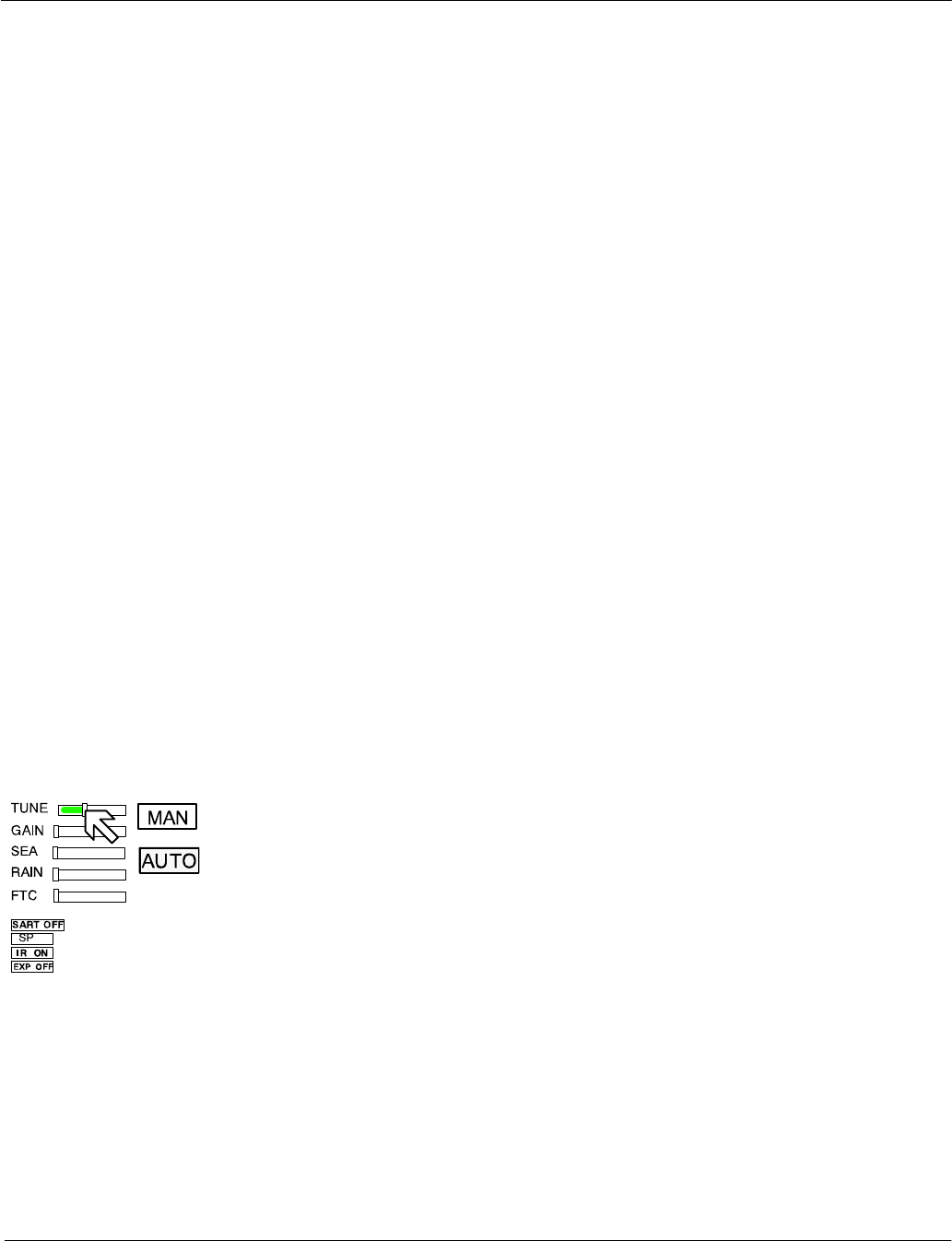
2.3.1.2 TUNE
MANual TUNE
The tune function uses the trackball to control tuning of the receiver frequency to
match that of the transmitter. The tuning should be adjusted on the medium or
long range scales (6 NM or higher) that show radar returns.
For a preliminary manual setting:
Use the trackball to place the cursor on the TUNE slider then press the Left
trackball button.
Rotate the trackball for maximum deflection of the slider.
As this setting must be averaged over a complete antenna revolution, a peak
detector is included for operator convenience.
Operator Manual
2−26
3748DOC020102 Edition: 14.JAN.2005
The tip of the tuning bar (yellow color) remains at the peak signal detected
during one complete revolution of the antenna.
NOTE
Bear in mind the fact that the transmitter frequency will drift for the first thirty
(30) minutes of operation from a cold start due to inherent magnetron
characteristics. As a result of this, the receiver tuning will change during this
time and a final tuning adjustment should be made after approximately thirty
(30) minutes of operation. The tuning should also be checked at four−hourly
intervals thereafter.
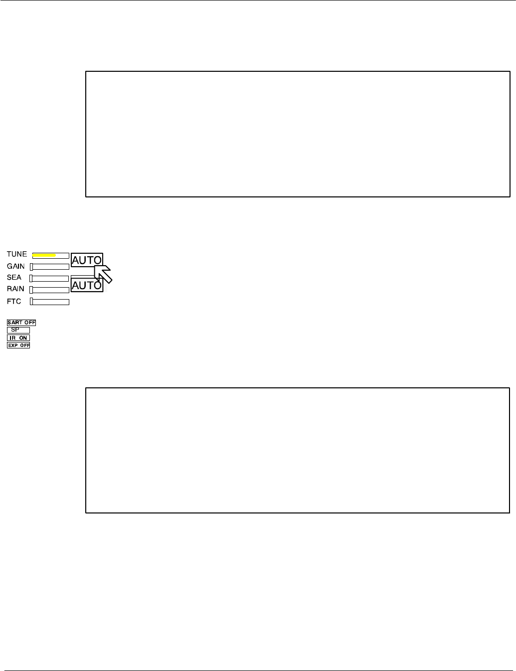
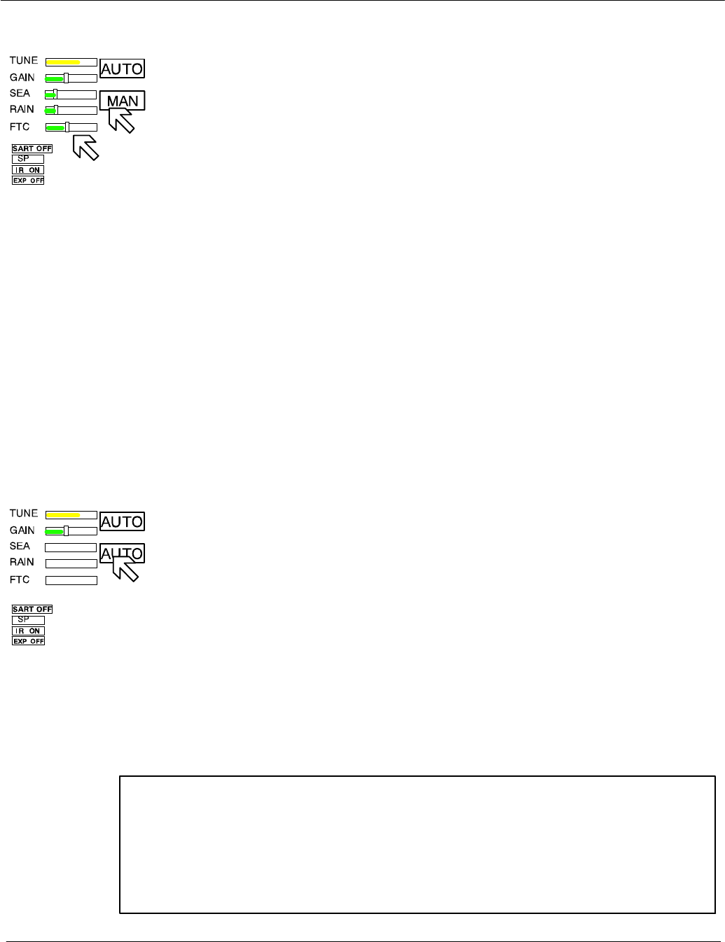
AUTO TUNE (only available in Master mode)
When auto tuning is activated, manual tuning is not available. The slider symbol
is hidden and the tuning bar color changes to yellow.
Auto tune is only available if the NSC radar is working in Master mode.
NOTE
With automatic receiver adjustment, the tendency indicator adjusts itself to
the maximum value.
−If the magnetron is at the end of its service life and the transmission
spectrum has become abnormal, select manual tuning.
Step 1
Step 2 Step 1
Operator Manual Raytheon Marine GmbH
Germany
R
NSC 18
RADAR
2−27 3748DOC020102Edition: 14.JAN.2005
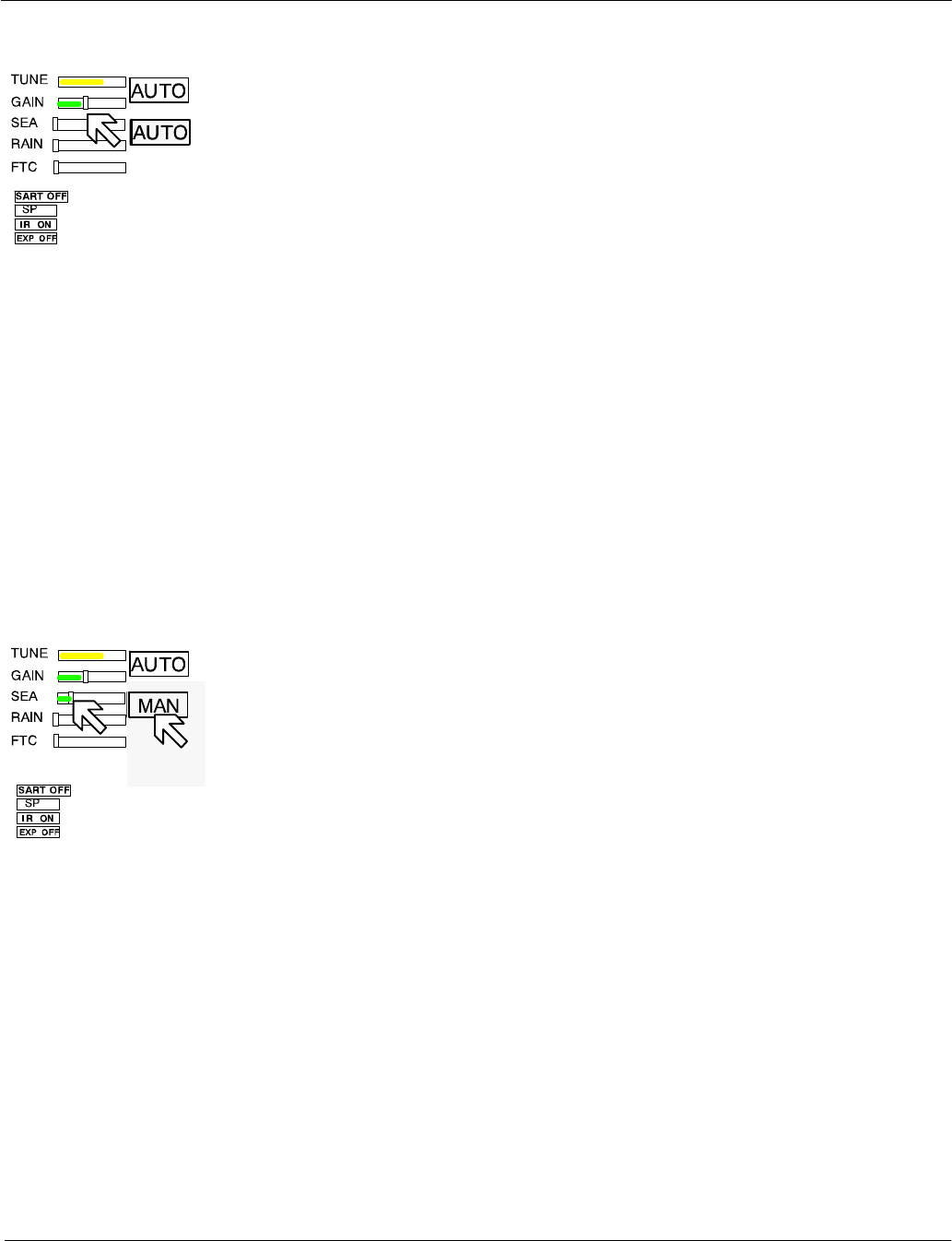
2.3.1.3 GAIN
The GAIN control adjusts the sensitivity of the radar video. If properly adjusted,
the GAIN control results in noise appearing as a light speckle at the dim level.
This light speckle setting results in maximum detectability of targets against
background noise. If GAIN is set too low, weak or distant targets could be
missed. Excessive gain increases background noise and could make target
detection more difficult. A gain slider is provided to indicate the GAIN control
setting.
Once the GAIN control has been set, it will automatically maintain the same
setting for all ranges. It is not necessary to readjust whenever a new range scale
is selected. However, it should be adjusted to optimize the radar video as clutter
(sea and/or rain) conditions change.
The gain control function is active over its entire rotation range.
2.3.1.4 SEA
Step 1
Select MANual mode
Step 2
The Sea control is used to suppress radar returns which are the result of radar
signals reflected from waves. This effect is commonly known as sea clutter.
The effects of sea clutter are greater (more reflected energy) at close range and
vary with wave height and wind.
It should also be noted that sea clutter is reduced on the leeward side of the ship
as the retreating wave fronts do not provide as many radar returns as oncoming
waves.
Small targets (buoys etc.) often return nearly the same energy as do the waves
and can therefore be lost in the clutter. However, since sea clutter is random in
nature, the gain and clutter processing circuitry together with the SEA control
allow the operator to reduce the sea returns to a light background speckle at low
brightness level while maintaining targets in the sea clutter at full brightness.

Operator Manual
2−28
3748DOC020102 Edition: 14.JAN.2005
The effect of the Sea control is at its greatest at short range. Its effect reduces
progressively as the range increases. At a range determined by the height of the
radar antenna above the water (and other factors), the effect of the SEA
control ceases altogether. This is typically about 8−10nm.
The ideal sea control setting will reduce sea returns to a light speckle.
Scan−to−scan integration will keep the sea returns at a low brightness level,
while targets in the sea clutter will be shown at full brightness.
The sea clutter control should be adjusted in small increments, with pauses to
observe 3 scans for the results.
In heavy sea clutter, some clutter peaks may come through at brighter levels,
especially rollers, so an average setting should be chosen. It is important to note
that if the Sea Clutter control is adjusted to completely remove all clutter, then
some targets may not be detected.
NOTE
The NSC uses gyro and speed information as part of the clutter removal
process. It is therefore highly recommended that you use gyro stabilization
and ensure that the manual speed or speed log input is accurate.
In heavy wind driven seas where more sea clutter appears on the windward side
of the ship, a slight amount of FTC can balance the clutter (see chapter 2.3.1.6)
Then adjust the SEA control to reduce sea clutter. If too much SEA is applied
during periods of light clutter, then a band of noise could appear on the edges of
the sea clutter.

Step 1
Step 2 Step 1
Operator Manual Raytheon Marine GmbH
Germany
R
NSC 18
RADAR
2−29 3748DOC020102Edition: 14.JAN.2005
2.3.1.5 RAIN RATE
Step 1
Select MANual mode
Step 2
The function of the RAIN control is to enable the operator to suppress radar
returns which are the result of radar signals reflected from rain drops.
This effect is commonly known as rain clutter. As with sea clutter, the rain clutter
tends to mask small targets (or large targets if the rain is intense).
When heavy rain is falling in the vicinity of the operator’s ship (up to 6−10 nm)
and the resulting rain clutter is obscuring nearby targets, then the rain rate slider
should be used. Advance the rain rate control slightly and observe the results
(wait 3 scans).
The ultimate goal is to reduce the nearby rain clutter until it is a very light speckle
at the dim level. This setting will reduce the rain returns and will have little effect
on strong constant target video returns. Weaker targets (usually appear where
rain returns are less intense) may be suppressed along with the rain.
Most of these weaker targets can be restored by making an FTC adjustment
(see chapter 2.3.1.6).
Step 1
Step 2
Step 1
Operator Manual
2−30
3748DOC020102 Edition: 14.JAN.2005
2.3.1.6 Filtering rain clouds FTC
Step 1
Select MANual mode
Step 2
FTC is responsible for differentiation or filtering of rain clouds. Advance the FTC
control slowly (remember the 3 scans) until only the leading edges of the rain clutter
are visible. As the FTC is increased, weaker returns will reappear. Stronger returns
will begin to reduce in the visible area. The best setting will be a balance between
restoration of weaker returns and adequate size of the stronger returns.
Use the trackball to place the cursor on the slider then press the upper trackball.
Rotate the trackball to increase or decrease the amount of FTC.
Adjusting the FTC will also reduce the land echoes and thin out larger targets.
With FTC on and in a light sea, it is possible to overcompensate with the SEA
control; if so, with FTC ON a false noise ring may be displayed.
Too much FTC will shorten or delete RACON responses.
2.3.1.7 CFAR
Step 1
AUTO
When AUTO is activated, the slider symbols for SEA, RAIN and FTC are hidden
and the bar color changes to yellow.
This AUTO mode activates the CFAR (Constant Fault Alarm Rate) functionality.
CFAR describes a control algorithm, which uses the evaluation of echoes to
calculate statistical average values for SEA, RAIN and FTC.
These average values are used for optimization of the radar video.
NOTE
Use of CFAR simplifies radar video optimization. However, depending on
the weather conditions misinterpretations are possible.
In case of doubt, switch to MANUAL compensation for SEA, RAIN and
FTC to clarify the situation. RACONs are best seen in MANUAL.
Operator Manual Raytheon Marine GmbH
Germany
R
NSC 18
RADAR
2−31 3748DOC020102Edition: 14.JAN.2005
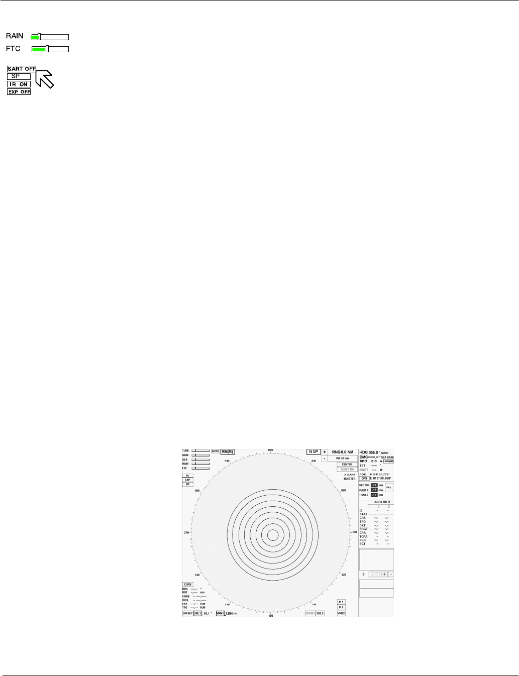
2.3.1.8 Search and rescue transponder SART ON/OFF (option)
The SART ON/OFF does not activate ownship SART. It changes receiver
bandwidth to improve SART detection by this radar.
Information about the SART transponder
The purpose of the SART is to trigger a secondary alarm when search and
rescue units are searching for a life raft/lifeboat in distress. The SART will help
the units to pinpoint exactly where the distressed boats are located in a large
area. This is done with the help of the radar on the search ship or helicopter.
When the SART is interrogated (hit) by a radar signal, it will immediately start to
transmit a number of sweeps covering the complete maritime 3 cm radar band.
These sweeps are detected on the radar screen and used to navigate directly
towards the distressed life raft, for details on radar display.
The maximum distance to a ship will normally be about 10 NM or approximately
30 nm to a helicopter, depending on the helicopter’s altitude. The transponder
will not give any alarms further away than this.
How is this situation displayed on the NSC Radar?
This situation appears automatically in the radar video.
The echo display in the radar video depends on the distance of the transponder
from your own ship and can be interpreted as follows.
Figure: 2−15 SART transponder < 0.2 NM
Operator Manual
2−32
3748DOC020102 Edition: 14.JAN.2005
The SART transponder is in the immediate vicinity.
Figure: 2−16 SART transponder ~1 NM
The SART transponder is in the vicinity.
Figure: 2−17 SART transponder > 2 NM
The SART transponder is a long distance away.
see
Figure: 2−18
Operator Manual Raytheon Marine GmbH
Germany
R
NSC 18
RADAR
2−33 3748DOC020102Edition: 14.JAN.2005
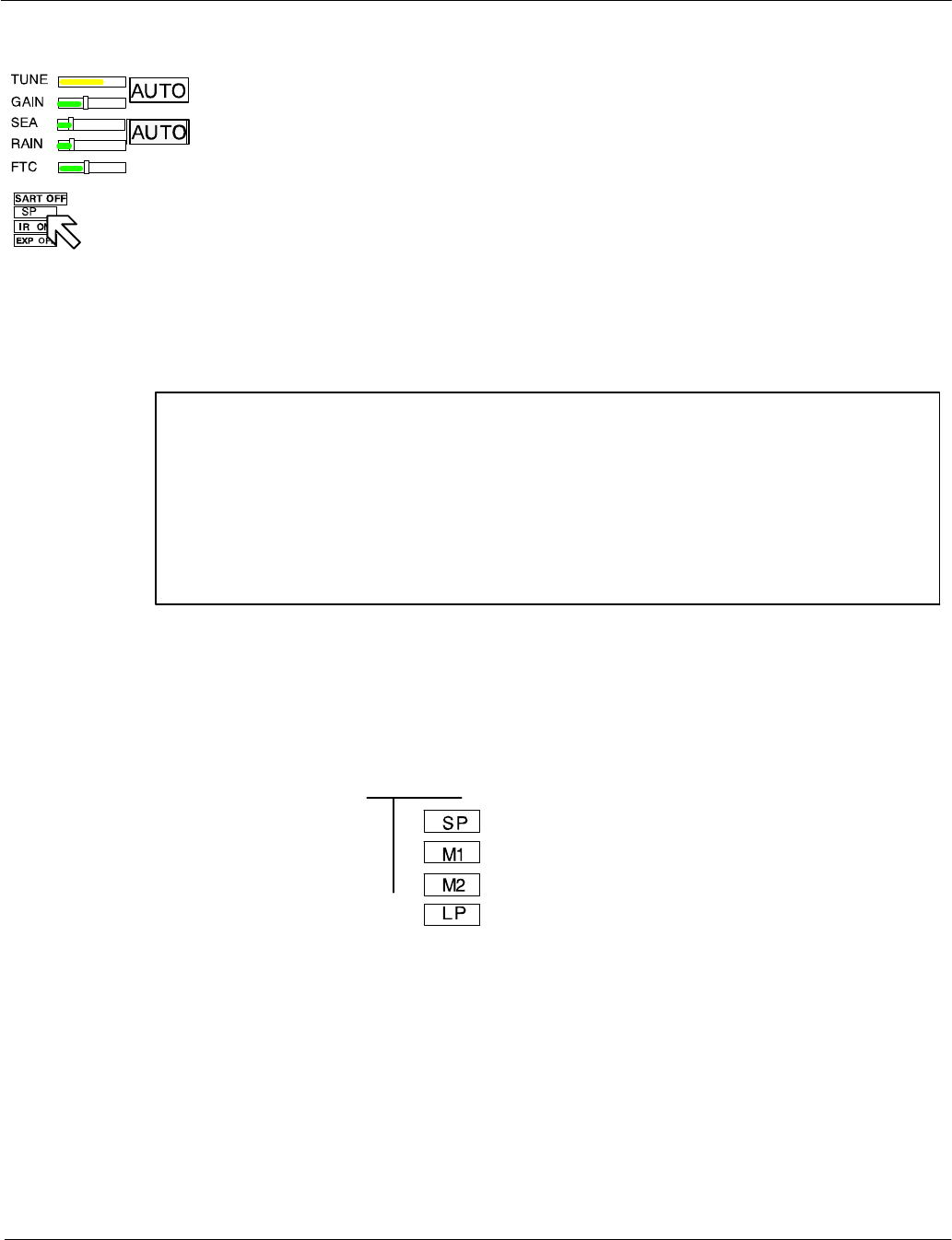
2.3.1.9 Pulse width selection
The pulse width toggle field allows selection of the desired transmitter pulse
width for the current range scale selected. If there is no pulse width toggle field,
this indicates that it is not available for the range currently being used.
Selecting this toggle field allows the pulse length to be switched e.g. from short
pulse to medium pulse and vice versa to optimize target discrimination with
respect to the selected range.
NOTE
Use of a longer pulse improves target reception but, at the same time,
increases clutter returns.
When a shorter pulse is used, reception of some weaker targets will
decrease, but clutter will also decrease, resulting in better target detection.
The available pulse width selections for the NSC display are illustrated in
Figure: 2−18.
SHORT pulse = 0.08µs
MED1 pulse = 0.3µs
MED2 pulse = 0.6µs
LONG pulse = 1.2µs
10Kw transceiver
6 ft. antenna
Information
A longer pulse width means;
more power, stronger targets returns but also more disturbances.
Long pulses are necessary in high ranges to detect small targets
more effectively.
Figure: 2−18 NSC pulse width
Operator Manual
2−34
3748DOC020102 Edition: 14.JAN.2005
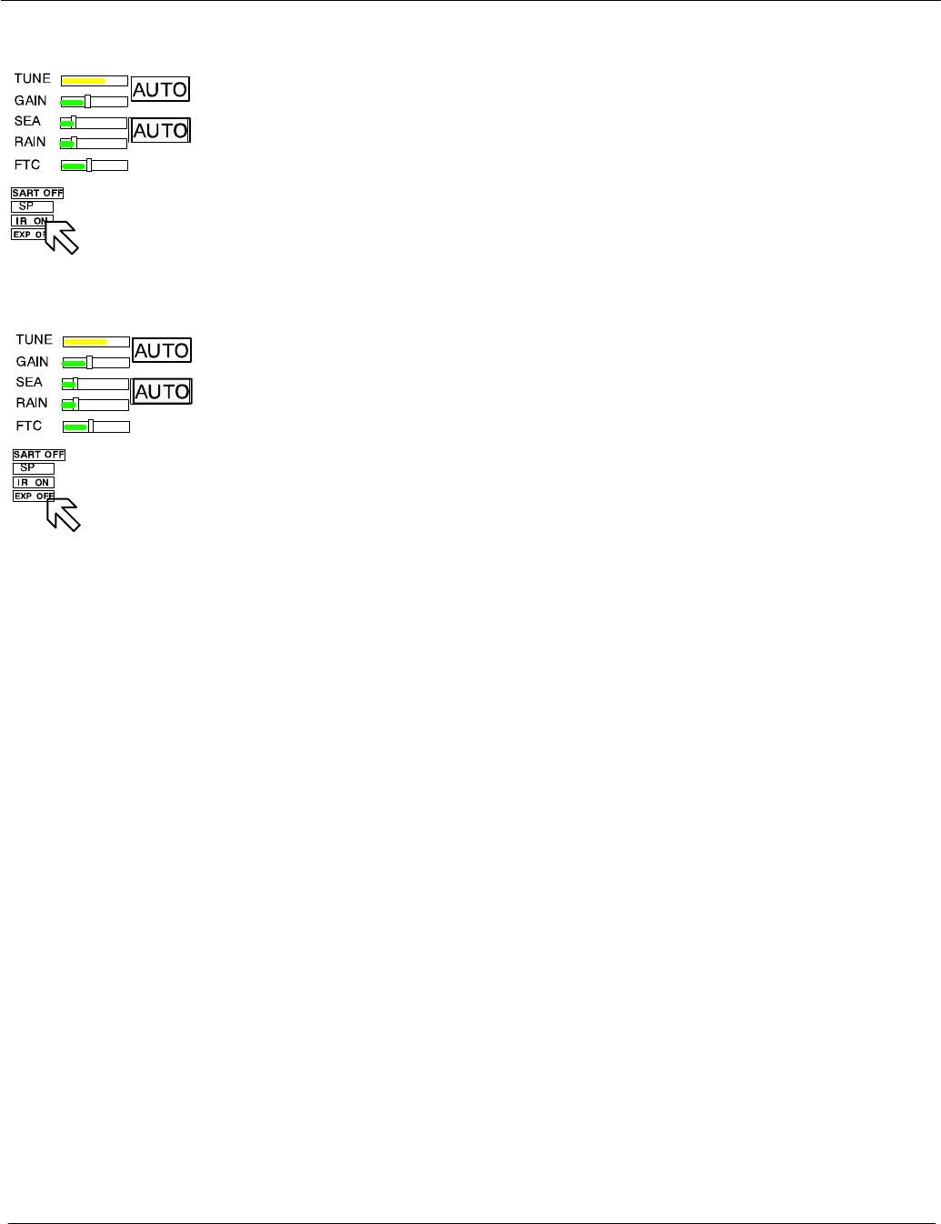
2.3.1.10 Interference selection
The interference toggle field allows selection of the function interference ON or
OFF. The function of interference rejection is activated to eliminate echo effects
caused by other radar system from ships nearby.
2.3.1.11 Echo expansion
By selection this toggle field, the function of echo expansion is activated to
magnify small radar echoes.
Left
Operator Manual Raytheon Marine GmbH
Germany
R
NSC 18
RADAR
2−35 3748DOC020102Edition: 14.JAN.2005
2.3.2 Radar video displays
2.3.2.1 Ship heading marker
When the button is pressed, only the ship heading marker (SHM) display is
turned OFF, enabling the operator to view a target that is obscured by the
heading line.
When the button is released, the heading line is turned ON again.
2.3.2.2 Relative Motion (R), Relative Motion (T), True Motion
The RM (R), RM (T), TM legend in the upper left of the display shows the current
mode for radar video presentation. Position the cursor on the toggle field and
press the trackball button. Select the preferred motion.
General
If Relative Motion is selected, your own ship is stationary and all other objects,
including land masses, buoys, ships at anchor and ships in motion, move with
the correct relative speed and course.
In this case Relative Motion provides two special settings linked to the TRAILS
toggle field (see chapter 2.3.6.2).
The following figures show the differences in the radar video.
Relative Motion
RM (R) for relative motion and relative trails
RM (T) for relative motion and true trails
Set 1 Set 2
Operator Manual
2−36
3748DOC020102 Edition: 14.JAN.2005
Relative Motion without TRAILS
If no trails (set 2) are activated, the RM (R) and RM (T) are identical.
Set 1
Set 2
Buoy
Ship in motion
Figure: 2−19 Relative Motion without TRAILS
Set 1 Set 2
Operator Manual Raytheon Marine GmbH
Germany
R
NSC 18
RADAR
2−37 3748DOC020102Edition: 14.JAN.2005
Relative Motion (R) with TRAILS
A ship in motion in the same speed and heading (e.g. shipping lane) is displayed
with no afterglow in the radar video.
Relative trails is the original radar method to view plot history (also with EBL) to
quickly see which approach own ship. In Figure: 2−20 the other ships are all
heading west (ARPA data). Relative Trails / BCR information is an option for
experienced radar operators.
Figure: 2−20 Relative Motion (R) with TRAILS
Set 1 Set 2
Operator Manual
2−38
3748DOC020102 Edition: 14.JAN.2005
Relative Motion (T) with TRAILS
In this case, land masses, buoys, ships at anchor, etc. appear exactly as they
are, as stationary objects. Objects in motion, including your own ship, move
across the radar video with the correct true speed and course. The trail afterglow
displays the track.
Figure: 2−21 Relative Motion (T) with TRAILS
Set 1
Set 2
Buoy
Ship in motion
TRUE MOTION
If True Motion is selected, land masses, buoys, ships at anchor, etc. appear
exactly as they are, as stationary objects, while objects in motion, including your
own ship, move across the operating screen with the correct true speed and
course.
True Motion mode is available for range scales from 0.25 nm to 24 nm
(inclusive) and in either N UP or C UP mode. If the range moves above 24 NM,
the origin of your own ship is centered.
Selected by
or
Operator Manual Raytheon Marine GmbH
Germany
R
NSC 18
RADAR
2−39 3748DOC020102Edition: 14.JAN.2005
2.3.2.3 North Up, Head Up, Course Up and Repeater Up
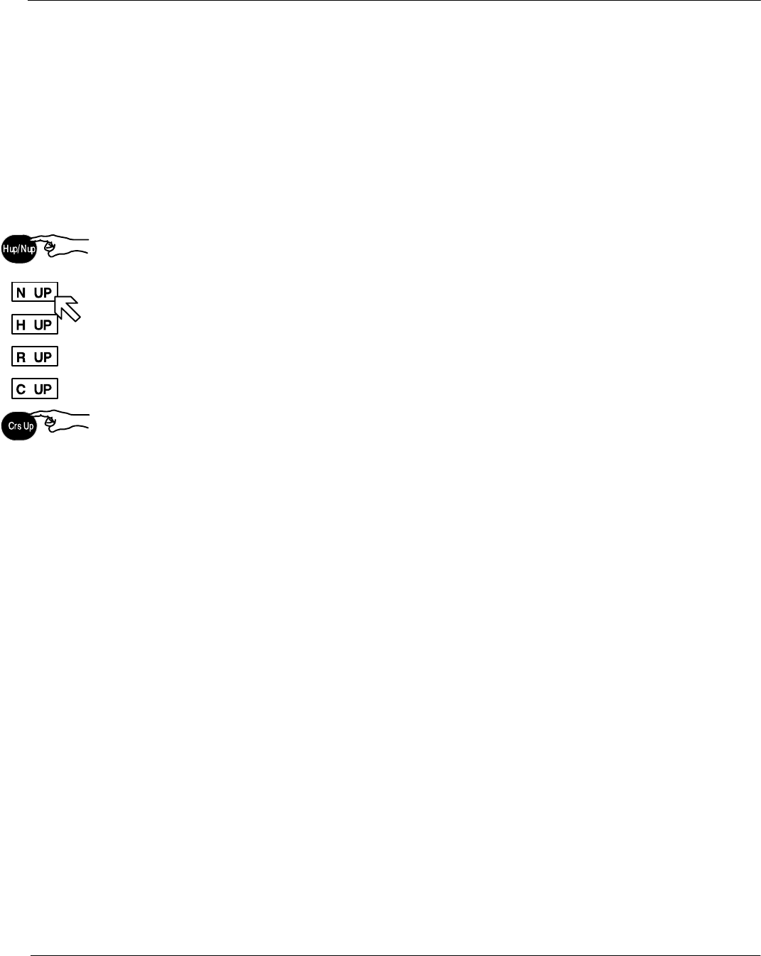
This toggle field is used to select either North Up (N UP), Head Up (H UP),
Course Up (C UP) or Repeater Up (R UP) as the orientation of the radar video.
The N UP, H UP, C UP and R UP legend in the upper right of the display shows
the current orientation mode of the radar video, radar rose and SHM display.
Position the cursor on the toggle field and press the Left button. Select the
preferred motion.
The North Marker continues mark compass north on the radar rose (red circle).
North up means that geographic north is upwards.
−Stabilized operation−
Gyro information is required for N UP operation. When the unit is switched on,
N UP is selected automatically. If the gyro is inoperative, an audible alarm
sounds and the words GYRO OUT appear in the WARNING MESSAGES area.
ARPA functions are disabled and H UP mode is automatically selected.
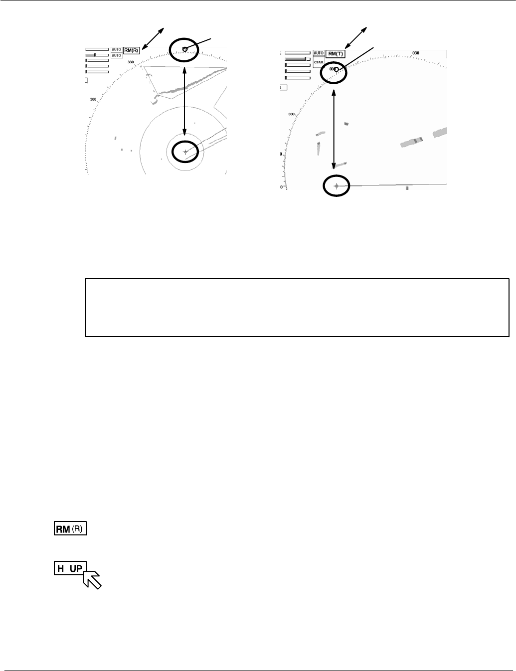
If N UP mode is selected, 000_ represents compass North (see Figure: 2−22).
Visual impression
The radar video is rotated to a northerly direction. North is at the top (000_). This
effect is comparable with an ordinary sea chart on which North is at the top.
The SHM shows the ship’s correct compass heading.
Response to a change of course:
The SHM rotates in line with the change of course.
The radar video remains stationary.
Relative or true
The radar video can be presented in Relative Motion (RM (..)) or True Motion (TM).
Step 1
Step 2
+
(manual)
Operator Manual
2−40
3748DOC020102 Edition: 14.JAN.2005
Figure: 2−22 North UP in (RM (R)) or (RM (T))
North UP North UP
North Marker
North Marker
Head UP means the heading is upwards
WARNING
Filter and Trails do not function in Head UP. Course UP is preferred.
The SHM is displayed relative to north. Rain and sea clutter will appear as high
level radar video.
−The radar video is not stabilized by the gyro compass
−The anticlutter functions RAIN, SEA, FTC are not available
−Radar bearings are relative bearings (lateral)
−TRUE MOTION is not possible
−ARPA continues to function
DManual
Head UP alignment (Step 2) can only be selected using the Relative Motion
preset (step 1).
DAutomatic
If the gyro compass heading is not available, the radar will switch to
Head UP mode automatically.
Transfer
change of
heading to
the radar
video
Operator Manual Raytheon Marine GmbH
Germany
R
NSC 18
RADAR
2−41 3748DOC020102Edition: 14.JAN.2005
Visual impression
Head UP corresponds to the line of vision “ship’s head up”.
Change of course
The radar video rotates in line with the change of course.
The SHM remains at heading upwards (relative) (000_).
Relative or true
The radar video can only be presented in Relative Motion (RM (..)).
Course UP means the course is upwards.
−Stabilized operation−
Visual impression
Course UP corresponds to the line of vision “ship’s head up”.
The SHM remains on course.
Change of course
The SHM indicates the change of course.
The radar video remains unchanged.
If the change of course is to correspond to the line of vision “ship’s head up”, the
button on the control unit must be pressed.
The radar video rotates in line with the change of course.
Relative or true
The radar video can be presented in Relative Motion (RM (..)) or True Motion (TM).
Functions
Filter, Trails and ARPA all functions in Course UP.
Functions
Filter, Trails and ARPA all functions in Course UP.

Operator Manual
2−42
3748DOC020102 Edition: 14.JAN.2005
Repeater UP means the repeater indicator is upwards
−Stabilized operation−
WARNING
Filter and Trails do not function in Repeater UP. Course UP is preferred.
Repeater UP is a special feature of the NSC Radar. In this display mode, the
bearing scale behaves like a compass rose where the ship heading marker
(SHM) acts as the lubber line.
Visual impression
Repeater UP corresponds to the line of vision “ship’s head up”.
Response to a change of course
The radar video rotates in line with the change of course.
The radar rose rotates in line with the change of course.
SHM remains unchanged.
Relative or true
The radar video can only be presented in Relative Motion (RM (..)).
+
−
+
−
Operator Manual Raytheon Marine GmbH
Germany
R
NSC 18
RADAR
2−43 3748DOC020102Edition: 14.JAN.2005
2.3.3 Radar video settings
2.3.3.1 Range RNG
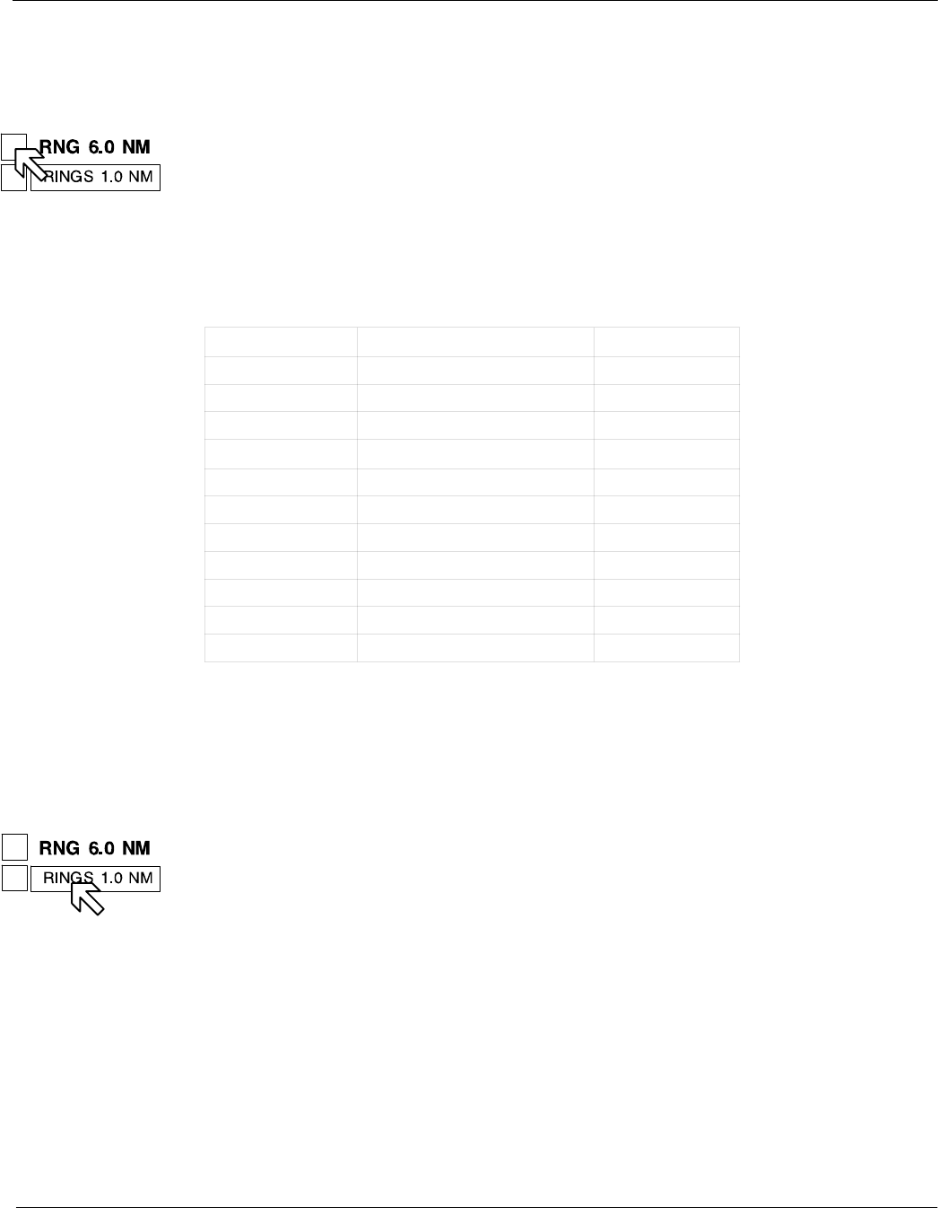
Range (RNG) shows the selected range area in NM.
The NSC allows up to 11 range settings.
Selecting the relevant toggle fields switches the range image displayed up or
down.
Range RNG in NM Range ring distance in NM Range rings RR
0.125 0.0625 2
0.25 0.125 2
0.5 0.25 3
0.75 0.25 3
1.5 0.25 6
3.0 0.5 6
6.0 1.0 6
12.0 2.0 6
24.0 4.0 6
48.0 8.0 6
96.0 16.0 6
Table:2 Overview range, SHM and rings
2.3.3.2 RINGS
The spacing between the rings is defined in the Range Rings (RR) toggle field.
The Range Rings toggle field is also used to turn range rings ON/OFF in the
radar video.
This toggle field automatically shows the distance between the rings in nautical
miles. Activating the toggle field displays the rings in the radar video.
or using
button
Operator Manual
2−44
3748DOC020102 Edition: 14.JAN.2005
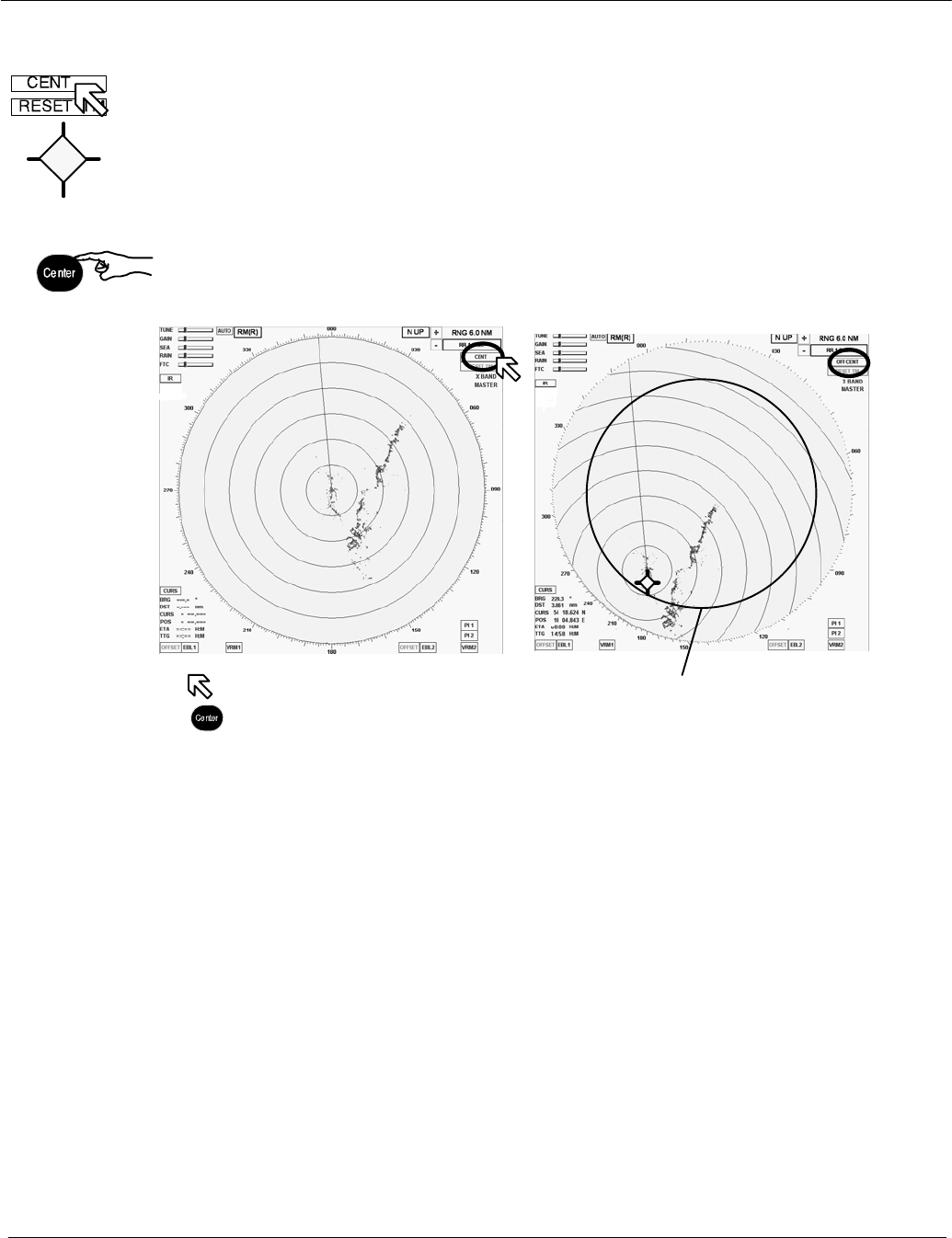
2.3.3.3 CENTer
Selecting this toggle field changes the name to OFF CENTer, the cursor jumps
into the upper area of the radar video range and the cursor symbol changes.
Place the cursor at a position within the permitted range and press the Left
button (trackball button).
Press the OFF CENTer toggle field (or button) if the radar video is to be shown in
the CENTer (see Figure: 2−23), or moved again (both).
Figure: 2−23 CENTer and OFF CENTer
action using cursor
or button
Approx. 65% of PPI radius
(circle shown for explanation only,
will not be visible)
Pressing CENter key is convenient to activate the OFF CENter cursor and track
ball is used to confirm the required position.

Operator Manual Raytheon Marine GmbH
Germany
R
NSC 18
RADAR
2−45 3748DOC020102Edition: 14.JAN.2005
2.3.3.4 RESET TM toggle field
RESET TM can only be used in conjunction with the TM preset.
With the TM setting, the radar video is carried in the direction of travel by approx.
65% of the PPI up to a radial limit (see Figure: 2−23) according to course
direction.
When this limit is reached, the radar video is reset by this 65% along the current
course.
RESET TM
Activating the toggle field resets the radio video.
Depending on the situation, this allows a maximum forward view in the radar
video.
Operator Manual
2−46
3748DOC020102 Edition: 14.JAN.2005
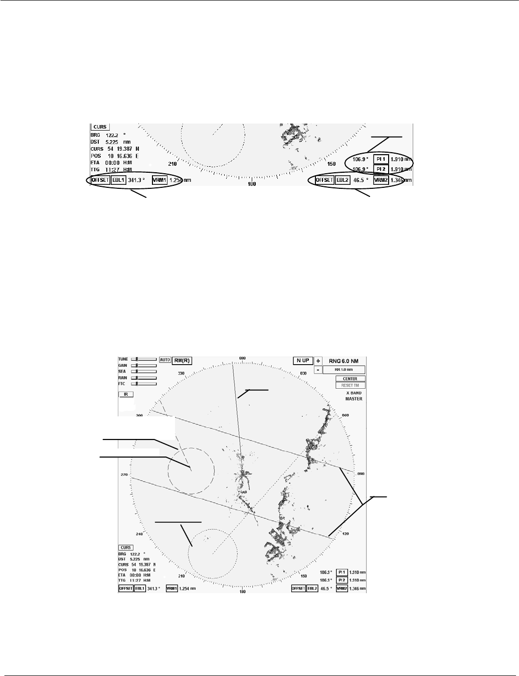
2.3.4 Electronic bearing lines (EBL) and variable range markers (VRM)
Electronic bearing lines and variable range markers are tools used to
determine bearings and distances.
Figure: 2−24 Select EBL and VRM
Group 3
Group 1 Group 2
TT
T
T
T
Here:
EBL 1/2 for Electronic bearing line with OFFSET function
VRM 1/2 Variable range marker with OFFSET function
PI 1/2 for Parallel index line
EBL1/ VRM1/
OFFSET
EBL2/ VRM2
OFFSET
SHM
PI1
Figure: 2−25 Radar video with 2 EBL, 2 VRM and PI
EBL1 root point
127.9°
EBL1 T
− EBL 1
VRM 1
− EBL 2
VRM 2
Operator Manual Raytheon Marine GmbH
Germany
R
NSC 18
RADAR
2−47 3748DOC020102Edition: 14.JAN.2005
2.3.4.1 Enabling EBL / VRM OFFSET using cursor
The electronic bearing line EBL is used for the bearing.
Starting from your own position, the EBL is placed on a desired target, e.g. using
the cursor. The current co−ordinates are displayed numerically to the right of the
toggle field (_).
The numerical display is normally displaying as true information when the GYRO
sensor is available. If the GYRO sensor is not available the numerical display
changes automatically to relative information.
T(rue) shows the numerical bearing value to the target as a true value
(in terms of North).
R(elative) shows the numerical bearing to the target as a relative value
(relative to ship heading).
The variable range marker VRM is used to mark a particular range circle.
The zone can be your own position or the EBL1 root point, for example. The
current radius is displayed to the right of the toggle field (NM).
Electronic bearing lines EBL and variable range markers VRM can be used
jointly as a group.
Identification of the EBL and VRM representation
The dotted EBL is drawn from your own ship through the cursor symbol.
Place the cursor on a selected target and press the Left button on the trackball.
The dotted VRM is extended from your own ship by moving the cursor symbol.
127.9°
EBL1 T
OFFSET
Operator Manual
2−48
3748DOC020102 Edition: 14.JAN.2005
Use the cursor to move the bearing line or the range marker.
Place the cursor on the EBL or VRM. Press the Right button on the trackball to
pick up and drag the EBL or VRM.
Press the Left button on the trackball to drop the EBL or VRM at the desired
position.
The OFFSET allows the EBL1 root point and the VRM1 origin to be moved
anywhere within the radar video as an EBL/VRM group.
NOTE
If the floating function is canceled, the point of origin of the EBL/VRM is
reset to the image center!
2.3.4.2 Editing EBL and VRM
The EBL and/or VRM can be placed and changed using the cursor or the
operator panel (see Figure: 2−26).
When using the operator panel, you are restricted to the EBL1 and VRM1 group.
The NSC provides 3 options for editing the EBL/VRM, which can be used
comprehensively as required.
Cursor
In this example, the EBL1 is shown, starting from the current position of the ship.
Position the cursor on the desired target and press the Right trackball button.
This places EBL1.
Select the Offset toggle field if EBL1 is to be moved parallel.
Pressing the Left button moves EBL1 to the new position.
The bearing and the variable range area can be changed at any time.
127.9°
EBL1 T
Left dialRight dial
Operator Manual Raytheon Marine GmbH
Germany
R
NSC 18
RADAR
2−49 3748DOC020102Edition: 14.JAN.2005
Bearing and cursor
Place the cursor on EBL 1, press the Right trackball button.
Find the desired target and press the Left trackball button.
Bearing / distance and toggle field with slider
Depending on the toggle field, the bearing (EBL) or the distance (VRM) can be
edited by moving the slider (see chapter 2.2.4.4).
Bearing / distance and operator panel
This alternative method of operation allows the EBL1/VRM1 function to be
displayed or adjusted quickly. Pressing the toggle switch releases the rotary dials
for the operation.
The EBL and VRM status LEDs light up.
The EBL/VRM is always placed at your own position.
Parallel movement is not possible when using the operator panel.
Adjust the EBL/VRM rotary dials to change the bearing (EBL) or the variable
range area (VRM).
The variable range area is directly linked to the range rings (RNG) and
adapted accordingly in the display.
2.3.4.3 Deactivating EBL and VRM
The EBL/VRM displays can be hidden by selecting the toggle field again.
Position the cursor on the desired toggle field.
Press the Left button.
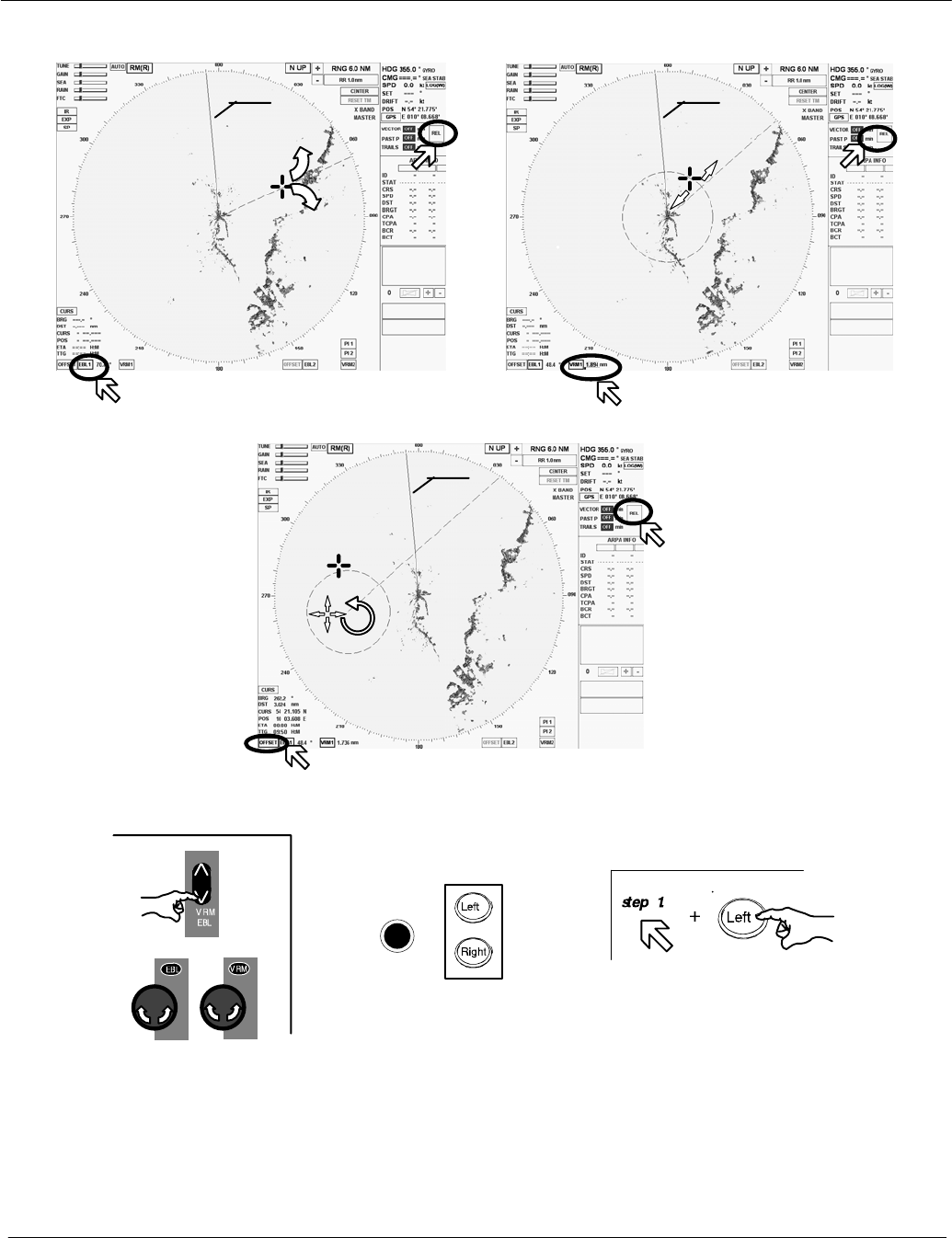
Operator Manual
2−50
3748DOC020102 Edition: 14.JAN.2005
Figure: 2−26 Navigating with bearing lines and variable range
markers
EBL and VRM
OFFSET
EBL
Left dial Right dial
SHM SHM
SHM
Operator panel
(EBL1/VRM1 only)
Sequence of actions
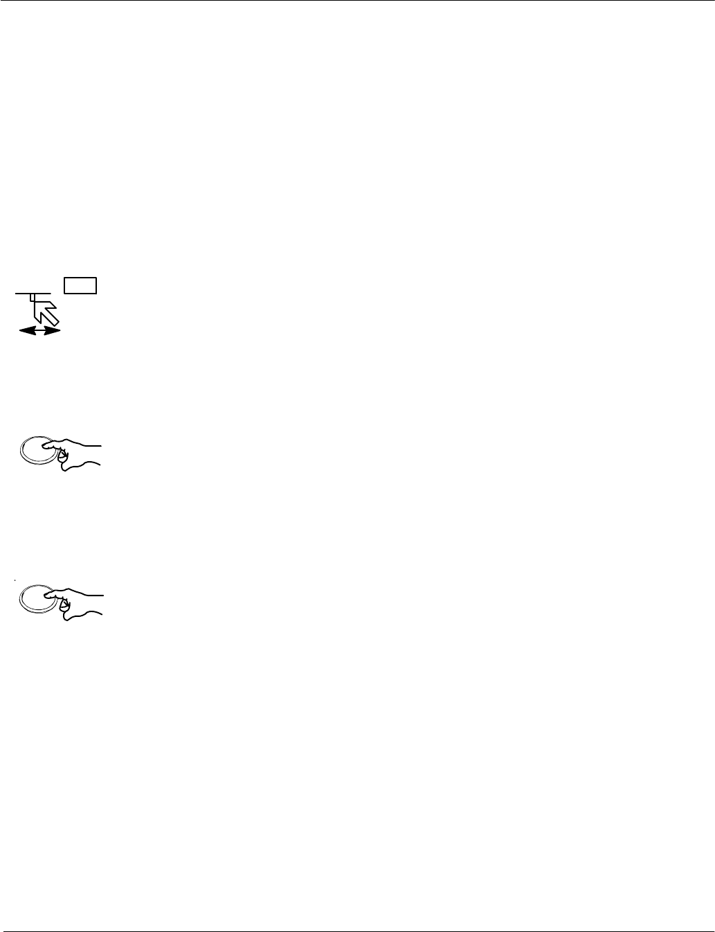
127.9° PI 1
T0.150 nm
Left
Left
Operator Manual Raytheon Marine GmbH
Germany
R
NSC 18
RADAR
2−51 3748DOC020102Edition: 14.JAN.2005
2.3.4.4 Parallel index line PI
Parallel index lines PI are used to mark the limits of areas or channels.
These lines can thus be used to observe the progression of a course, for
example.
The parallel index lines can only be called up and positioned (distance and
bearing) using the trackball.
After calling them up, the parallel index lines are shown in the radar video
parallel to the position in a ship’s head up direction.
In addition to the toggle field, the current relative or true direction (_) is shown on
the left and the current distance (nm) to your own position is shown numerically
on the right.
Changing the distance and/or bearing (see Figure: 2−27)
Position the cursor on a parallel index line.
Pressing the trackball button displays a symbol on each parallel index line. This
symbol corresponds to the image of your own position.
The distance for the parallel index lines can now be changed by moving the
cursor (step 1).
Pressing the trackball button changes the functionality from distance to bearing
(step 2).
The direction of the parallel index lines can now be changed by moving the
cursor. Position the cursor close to the compass rose and set the desired
direction.
Pressing the Left trackball button again concludes the two processes. The
symbols are hidden.
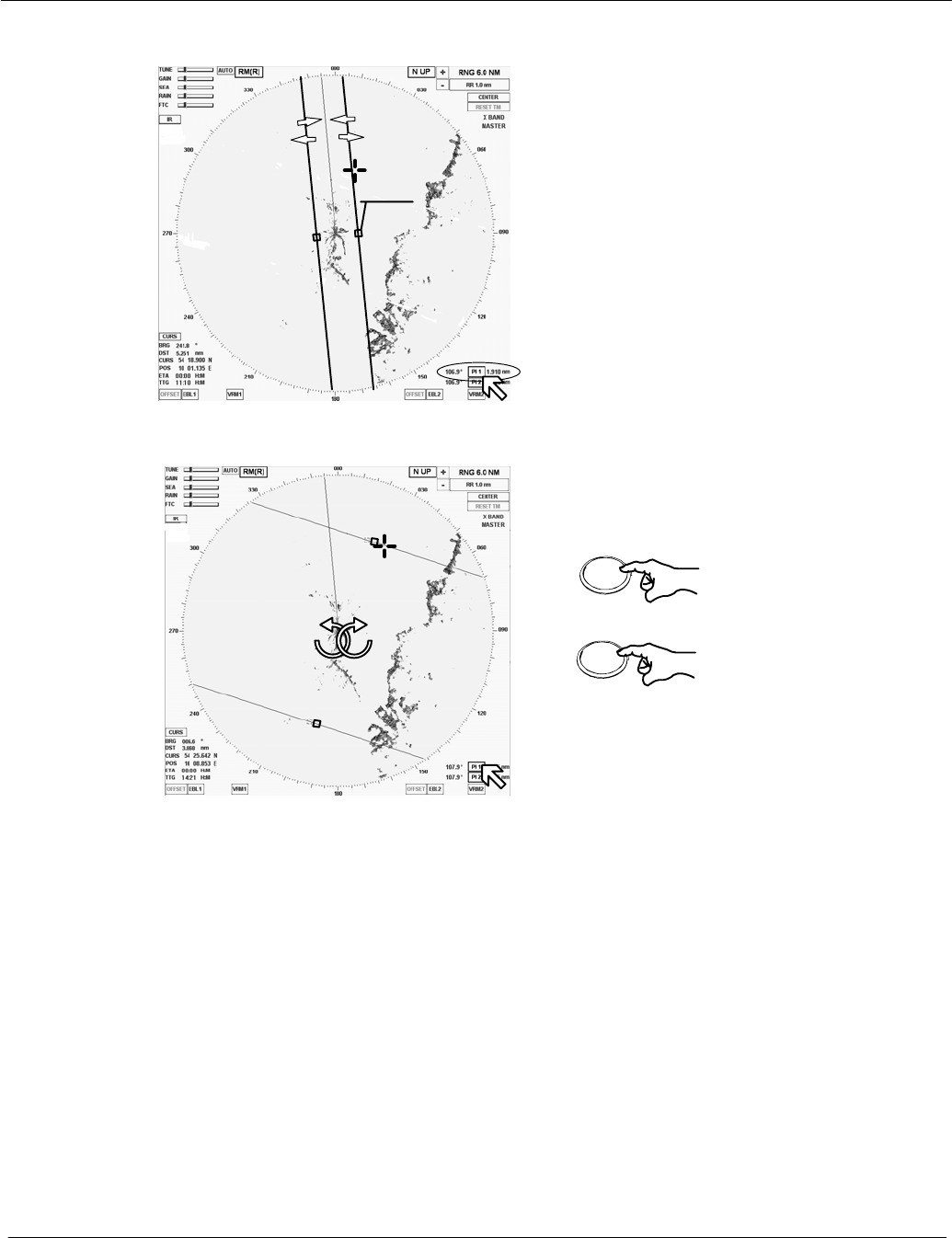
Operator Manual
2−52
3748DOC020102 Edition: 14.JAN.2005
Step 2
To change
the bearing
once
Press button again
to complete the task
Left
Left
PI 1 or PI 2 selected
Figure: 2−27 Navigating with parallel index lines
Symbols
Step 1
Select the distance
Step 3
Hiding PI 1 or PI 2
2.3.4.5 Deactivating the parallel index line PI
The PI displays can be hidden by selecting the toggle field again
(see Figure: 2−27).
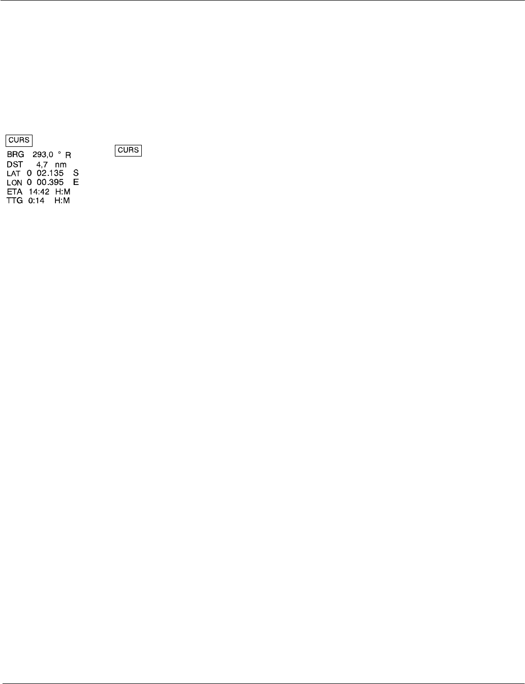
Operator Manual Raytheon Marine GmbH
Germany
R
NSC 18
RADAR
2−53 3748DOC020102Edition: 14.JAN.2005
2.3.5 Cursor information in the radar video
If the cursor is positioned within the PPI, the position data will be listed in the
cursor information area. This data is the cursor position (CURS POS), bearing
(BRG), distance (DST), estimated time of arrival (ETA) and time to go (TTG)
relative to your own ship.
DToggle field used to open the CURSOR READOUTS in the
function display area of the information panel (see
Figure: 2−28).
Select SHOW ETA + TTG or HIDE ETA + TTG or
Select MOUSE PARK POSITION ON/OFF.
DBRG bearing from cursor to your own ship’s position.
Use the central softkey (see Figure: 2−3) to select display of
true (T) or relative (R) values for the bearing.
DDST Distance information from cursor position to your own ship’s
position.
DLAT.... Latitude cursor position with geographic trend marker .
LON.... Longitude cursor position with geographic trend marker .
Selected from CURSOR READOUTS menu
DETA Estimated time of arrival at cursor position if present speed is
maintained.
DTTG Time to go from your own ship’s position to cursor position.
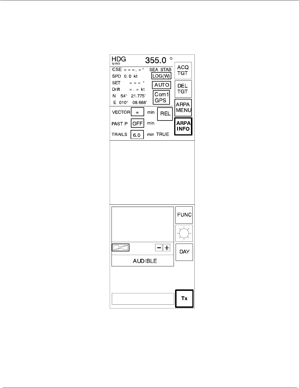
Operator Manual
2−54
3748DOC020102 Edition: 14.JAN.2005
2.3.6 Information panel
The Info Panel is structured as follows.
Display of own
ship data
Display and selection of
VECTOR data and
HISTORY TRACK
information
Display for
ALARM MESSAGES
Display for
TASK MESSAGES
Function display when us-
ing
a SOFTKEY or
a TOGGLE FIELD
Menu with softkeys
ACQUIRE a TARGET
DELETE a TARGET
ARPA MENU
ARPA INFO
FUNCTION MENU
DIMMER MENU
TRANSCEIVER
Tx / STANDBY
DAY / NIGHT
MODE
Figure: 2−28 NSC information panel
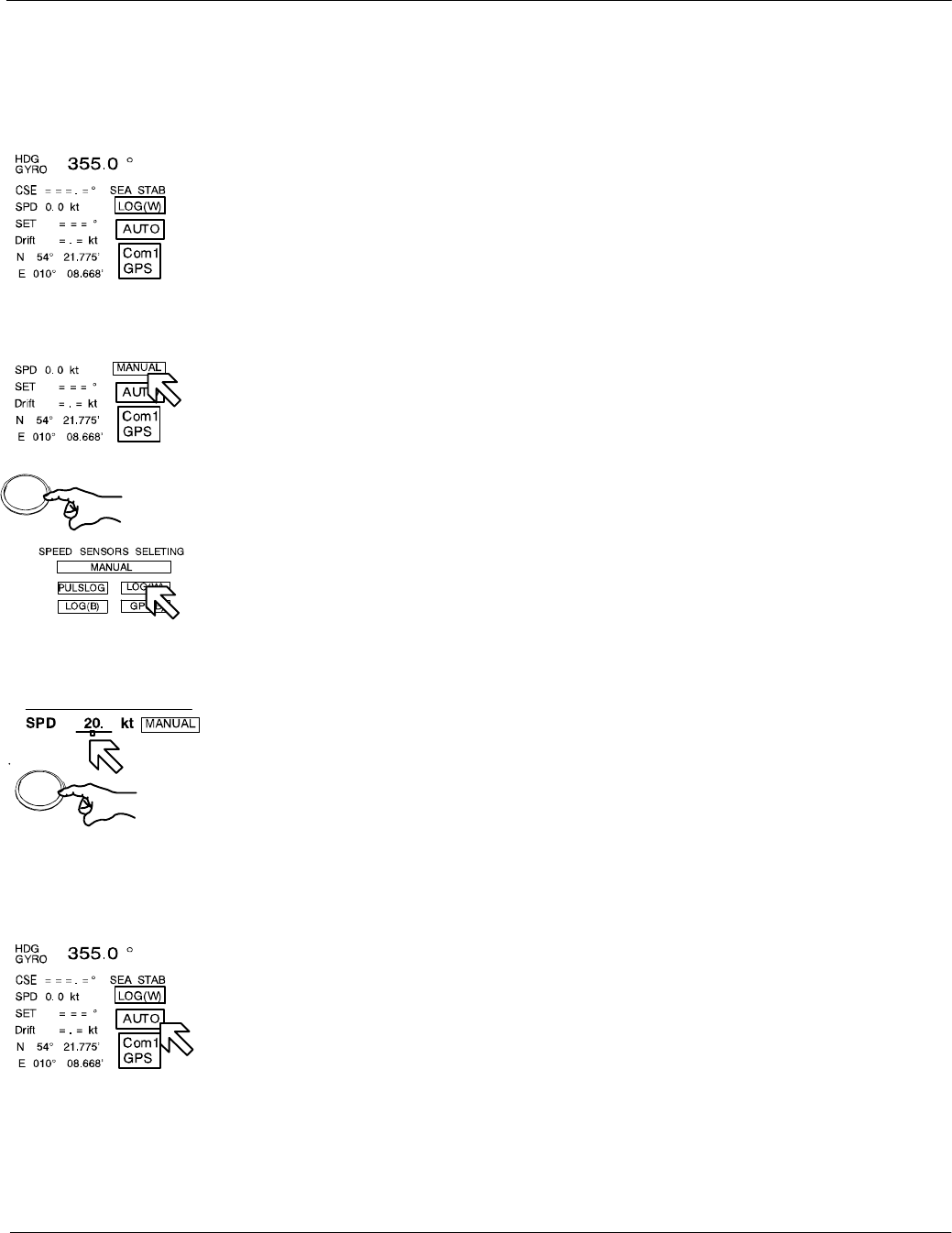
Left
Left
Press button
to save the value
Operator Manual Raytheon Marine GmbH
Germany
R
NSC 18
RADAR
2−55 3748DOC020102Edition: 14.JAN.2005
2.3.6.1 Display of OWN SHIP DATA
This field displays the following parameters for the ship’s motion:
DHEADING (HDG). The sensor type being used is indicated (e.g. gyro).
DCourse (CSE) is the true course over ground.
The difference between course made good and heading (HDG) is the drift
angle commonly referred to as SET.
DThe speed source defaults to MANUAL when the system is powered up.
If a speed log is to be used as the source input, then place the cursor
on the toggle field and press the trackball button.
The SPEED SENSOR SELECTION function display appears.
Select a sensor.
If the speed source is lost due to malfunction, the system reverts back to
MANUAL mode.
To set MANUAL input, use the slider function from the numeric indicator.
DIndication of SET and DRIFT values, automatically (AUTO) or using the
manual (MANUAL) input option.
SET indicates the drift bearing in _.
DRIFT indicates the drift speed in kt.
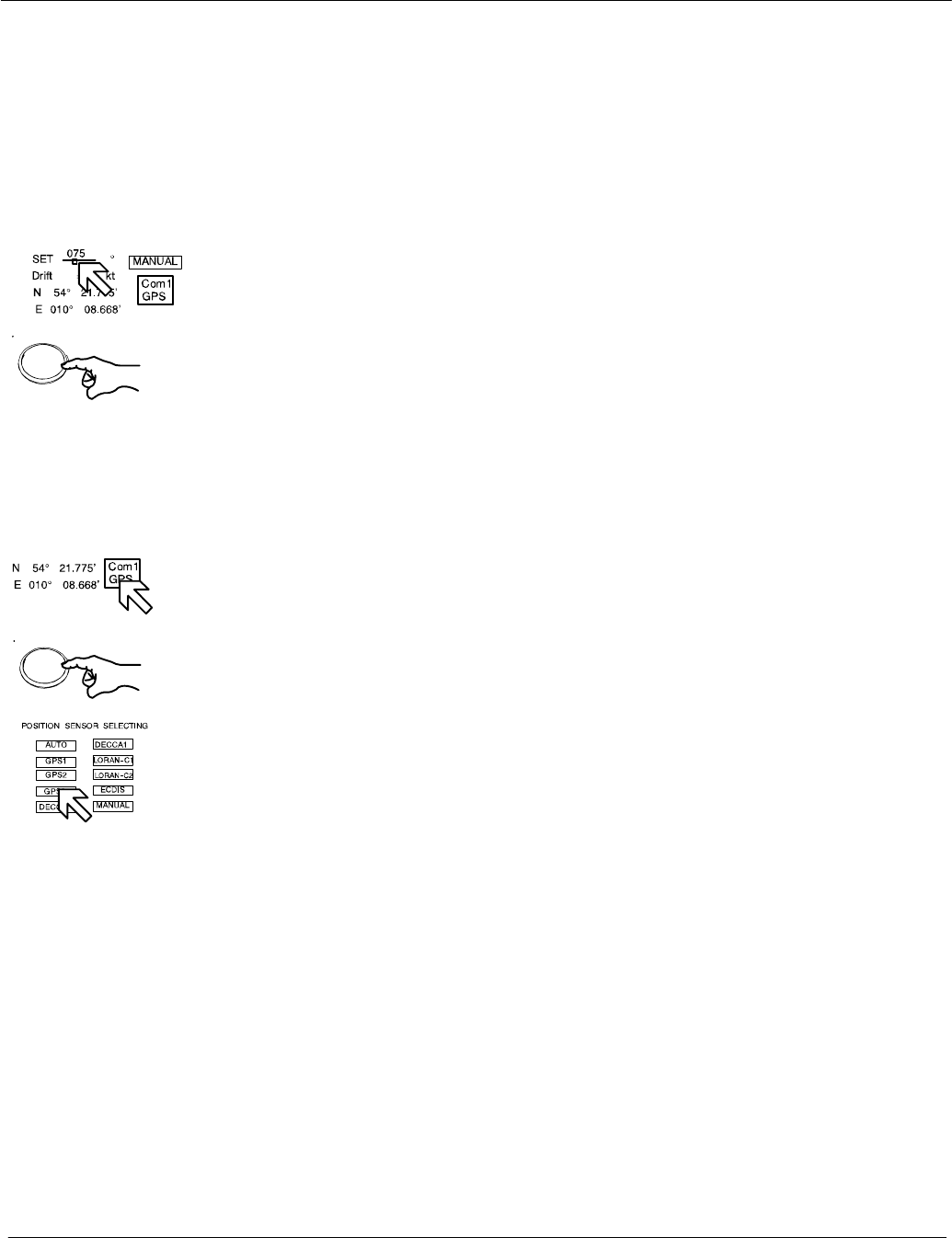
Left
Press button
to save the value
Left
Operator Manual
2−56
3748DOC020102 Edition: 14.JAN.2005
AUTO mode
Set and drift information is derived from the speed sensor input.
If the speed source is lost due to malfunction, the values will be canceled.
Select another speed sensor if possible or switch to manual or select
Reference Target.
MANUAL mode
Place the cursor on the toggle field and press and hold the Left button on
the trackball. To set MANUAL inputs, use the slider function and the trackball.
Release the Left button and press it again.
The parameter values for SET and DRIFT depend on one another.
Both parameters must therefore be defined separately but as a pair.
The NSC system will not accept a single parameter value as an input
value.
DPosition sensor selection to select the source sensor to obtain your own
ship’s position data in latitude and longitude.
If a position sensor is to be selected as the source input, then place
the cursor on the toggle field and press the trackball button.
The POSITION SENSOR SELECTION function display appears.
Select a sensor.
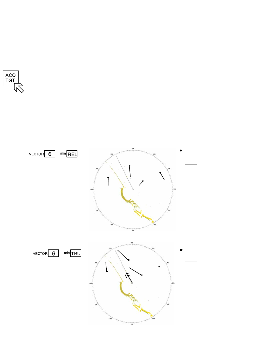
Operator Manual Raytheon Marine GmbH
Germany
R
NSC 18
RADAR
2−57 3748DOC020102Edition: 14.JAN.2005
2.3.6.2 Display and selection of VECTOR and HISTORY TRACK information
This information area allows the operator to select TRUE or RELATIVE VECTORS.
True vectors show the true course speed of the target and your own ship.
Relative vectors show the target’s relative motion compared to your own ship. Your
own ship does not have a relative vector. The vector length displayed is determined
by the selected time and indicates the distance to be traveled at a given speed.
First of all, the desired targets need to be acquired in the radar video
(see chapter 2.4.2).
DVECTOR
By selecting this softkey, you can define the vector time of the acquired targets,
defined by indicating the target vector length derived from the target speed; this
can be continuously adjusted between 0.0 and 30.0 min. (see Figure: 2−29).
Target acquisition
target vector
Relative vectors show the motion of
targets relative to your own ship. Ex-
tending the vectors allows you to
clarify any anticipated risk of colli-
sion.
Any stationary tracked target dis-
plays a vector opposite to your own
ship’s heading with a length equal to
your own ship’s speed.
The variable vector length
range is adjustable
between 0.0 and 30.0
min.
Display
information
Figure: 2−29 Vector information
The variable vector
length range is
adjustable between
0.0 and 30.0 min.
Target acquisition
target vector
Absolute vectors allow an
overview of the overall traffic situa-
tion (ships and navigation marks).
Extending the vectors allows you to
clarify any anticipated risk of colli-
sion.
Tracked targets which are not mov-
ing do not display a vector.
Display
information
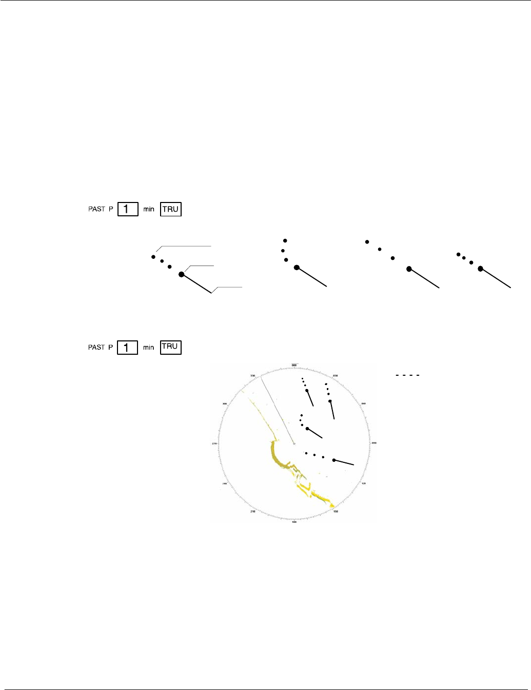
Operator Manual
2−58
3748DOC020102 Edition: 14.JAN.2005
DPAST POSITION
In addition to their symbol, all acquired targets can be given a history track.
With the PAST POSITION function switched on, a past position point is set at
the target symbol’s position (see Figure: 2−30).
The interval between two past positions can be adjusted.
Past positions indicate the last completed maneuver of the acquired
targets. In absolute (TRUE) view, it is possible to differentiate between
changes of course and changes of speed.
Vector
Target
Past position
High speed Low speedLast course change
Past position dot
Adjustable between
OFF and 60 min. (interval)
Display
Information
about past motion
characteristics
Figure: 2−30 Past position information
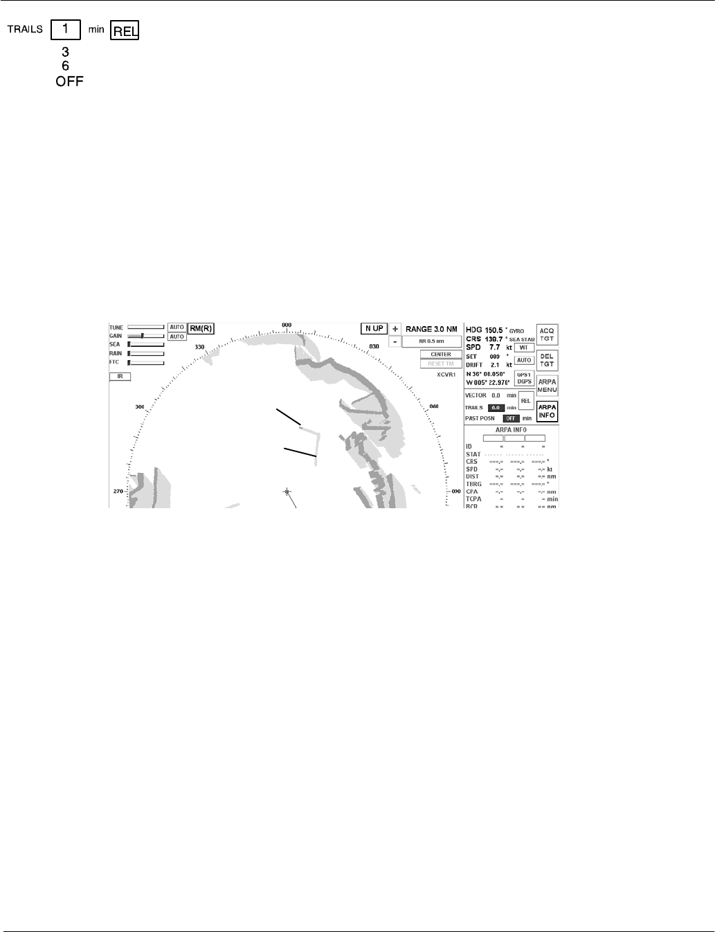
Operator Manual Raytheon Marine GmbH
Germany
R
NSC 18
RADAR
2−59 3748DOC020102Edition: 14.JAN.2005
DTRAILS
With this function, all targets located in the acquisition range are given an
artificial afterglow (see Figure: 2−31).
These afterglows indicate the route traveled
(length of artificial afterglow) in the set time.
Trails support situation assessment in the radar video.
Trails is an ARPA independent function that permits an assessment of the
current situation in the acquisition range.
Trails can be displayed as RELATIVE or TRUE.
Display
Information
about past motion
characteristics
See artificial afterglow in
the PPI
Target
Artificial
afterglow
Figure: 2−31 TRAILS information
2.3.6.3 Function display
This display shows a range of submenus.
The different menus are called up using the softkeys in the menu bar and the
toggle fields.
Some submenus are equipped with softkeys or toggle fields that can be used to
select further menus.
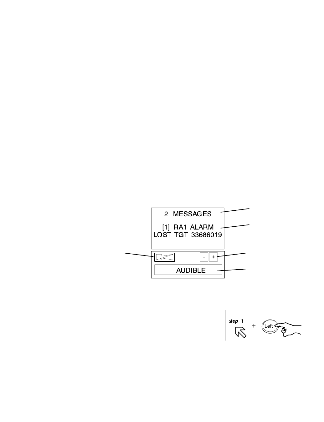
Operator Manual
2−60
3748DOC020102 Edition: 14.JAN.2005
2.3.6.4 Display for ALARM
Alarms are listed in an alarm message field until the cause no longer exists and
the operator has acknowledged them.
Alarms provide the operator with an indication of dangerous situations or sensor
failure.
Alarms are output when there is a situation that is critical to safety.
Alarms must be acknowledged, and will only be removed from the alarm list
when the situation that caused the alarm no longer exists.
These messages are displayed in the alarm readout display.
The alarm messages are numbered.
The alarm readout display is a scrolling field.
You can move up and down the alarm message list by pressing the
up and down buttons under the alarm readout display.
Figure: 2−32 Display for alarm messages
Indicates the total
alarm messages
Indicates the number
and the alarm mes-
sages
Scroll up and down
alarm messages
Softkey for
enabling/disabling the
AUDIBLE alarm
softbutton for
acknowledging
the Alarm
Messages
Sequence of actions
As Alarms are received, they are displayed in the chronological order in which
they occurred. If (and only if) all current alarms have been acknowledged, the
scroll function can be used to scroll through the.
When an alarm is received it will be placed at the top of the list. A new alarm will

Operator Manual Raytheon Marine GmbH
Germany
R
NSC 18
RADAR
2−61 3748DOC020102Edition: 14.JAN.2005
be shown in RED text strings on a WHITE flashing background.
Alarms that have been acknowledged will be shown as RED text string preceded
with a number.
The Alarm Acknowledge button on the control panel is used to acknowledge the
oldest active unacknowledged alarm. Once the alarm is acknowledged, the text
string will become RED, a number will appear at the beginning of the alarm text
string, and if needed the list will be automatically scrolled down in order to see
any other unacknowledged alarms in the list that are not currently displayed.
The following ALARM table shows all possible alarm indications and first
proposal how to handle an ALARM message.
ALARM MESSAGE a.) Problem Description
b.) Corrective Action
SLOW ANTENNA a. A signal from transceiver/Adaptive
Interface which indicates the antenna
is not rotating at the correct RPM
b. Refer to the maintenance section for
troubleshooting and repair
XCVR HIGH TEMP a. A signal has been received from the
transceiver indicating that excessive
temperatures are occurring
b. Refer to the maintenance section for
troubleshooting and repair
GYRO OUT
(HW GYRO OUT ALARM)
hw hardware
a. Gyro compass has become inopera−
tive. Indicates that an invalid signal
has been received
b. Refer to the maintenance section for
troubleshooting and repair
ANTENNA STOPPED a. A signal from the transceiver/Adapter
Interface which indicates that the
antenna is not rotating
b. Refer to the maintenance section for
troubleshooting and repair

Operator Manual
2−62
3748DOC020102 Edition: 14.JAN.2005
ALARM MESSAGE a.) Problem Description
b.) Corrective Action
DOWNLINK
(DOWN LINK ERROR ALARM)
a. An error has occurred on the
transceiver to the display link
b. Refer to the maintenance section for
troubleshooting and repair
UPLINK ERROR
(UP LINK ERROR)
a. An error has occurred on the display
to the transceiver link
b. Refer to the maintenance section for
troubleshooting and repair
LOST TGT
(LOST TARGET ALARM)
a.
b.
CPA TCPA
(CLOSEST POINT OF APPROACH or
TIME OF CLOSEST POINT OF
APPROACH)
a. Track will pass inside CPA limit
b. Only Tracks sooner than TCPA limit
can be alarm
GUARD ZONE
(GUARD ZONE INTRUSION)
a. Tracks already acquired have moved
into a area under watch
b.
NO TRIGGER a. Radar probably not transmitted
b.
NO POSITION
(POS OUT ALARM)
a.
b.

Operator Manual Raytheon Marine GmbH
Germany
R
NSC 18
RADAR
2−63 3748DOC020102Edition: 14.JAN.2005
ALARM MESSAGE a.) Problem Description
b.) Corrective Action
TRG RTN ERROR
(GEM TRG RTN ERROR ALARM)
TRG Trigger
RTN Return
a.
b.
TCM TIMEOUT ERROR
(TCM TIMEOUT ALARM ERROR)
TCM Transceiver Control Module....
a.
b.
ISU TIMEOUT ERROR
(ISU TIMEOUT ALARM ERROR)
ISU Interswitch
a.
b.
ISU MALFUNCTION ERROR
(ISU ERROR ALARM )
a.
b.
ISU EMERG MODE ERROR
(ISU EMERGENCY MODE ALARM )
a.
b.
TN INDICATOR
(GEM TN INDICATOR ERROR ALARM)
TN Tune
a.
b.
NO ACP
ACP Azimuth Commit Point
a.
b.
NO ARP
ARP Azimuth Reset Point
a.
b.
CAN BUS ERROR
(GEM CAN BUS ERROR ALARM)
a.
b.
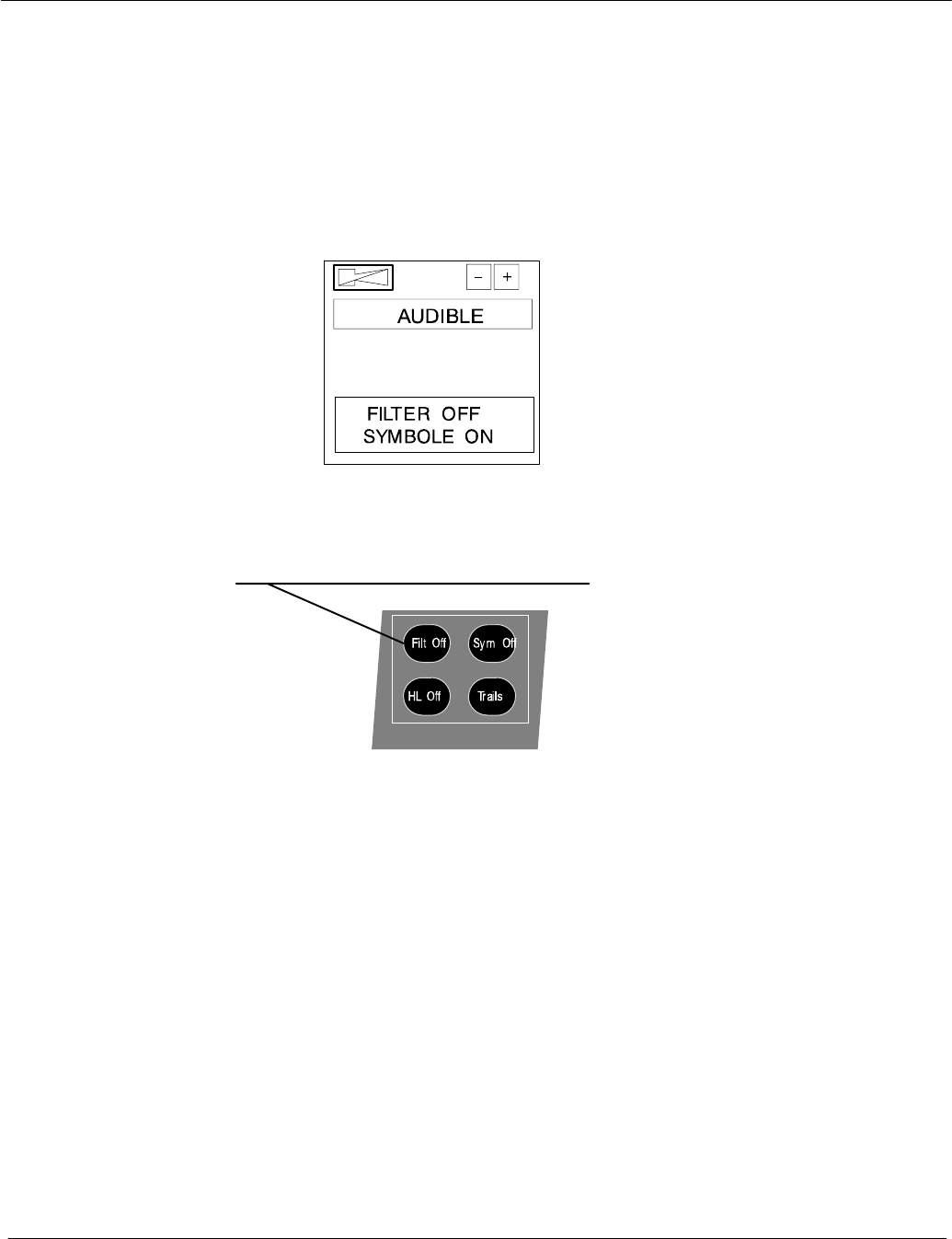
Operator Manual
2−64
3748DOC020102 Edition: 14.JAN.2005
2.3.6.5 Display for task messages
On this display, the status of the ANTI CLUTTER Filter and the
symbols (EBLs, VRMs, PL, ARPA zone, MAPs) are indicated in clear text.
The respective functions can be selected on the Radar Operator Panel via the
buttons FILT OFF and Sym Off.
Figure: 2−33 Display for Task Messages
Display for Task Messages
Radar Operator Panel
Filt Off is lit when FILTER is OFF
Filt Off is dark when FILTER is ON
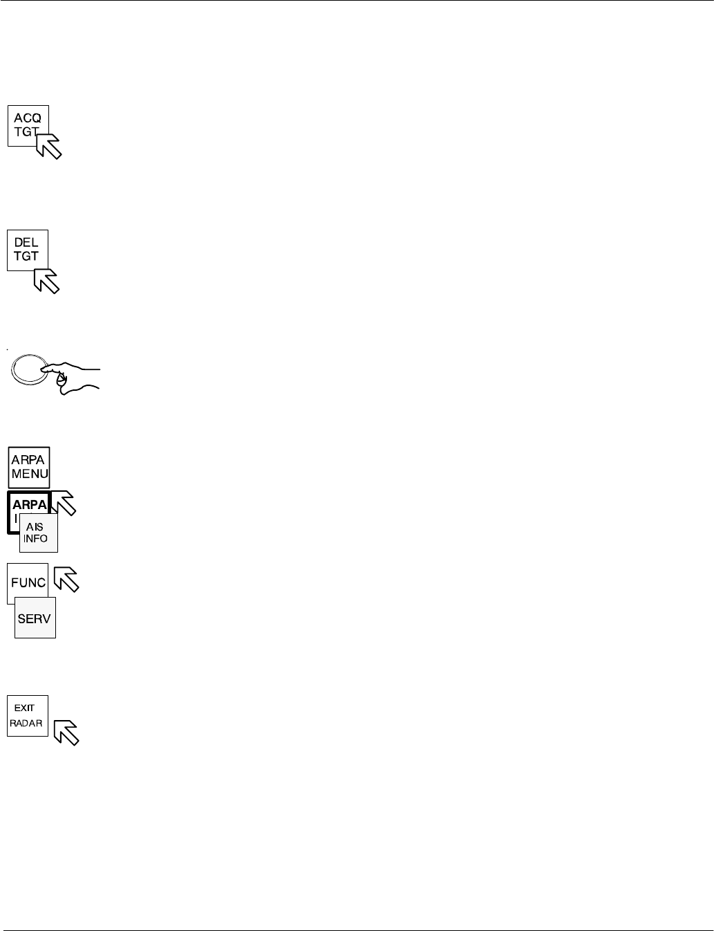
Left
Operator Manual Raytheon Marine GmbH
Germany
R
NSC 18
RADAR
2−65 3748DOC020102Edition: 14.JAN.2005
2.3.6.6 Menu with softkeys
ACQUIRE TARGET
This softkey allows manual acquisition of visible targets within the radar video
(see chapter 2.4.2).
DELETE a TARGET
The softkey function allows individual, acquired targets to be canceled, except
for those that have transmitted a collision alarm.
DPress the softkey
Position the cursor on the target to be canceled;
press the trackball button. The artificial target symbol on top of the echo is
eliminated (the echo is maintained).
ARPA MENU and ARPA INFO and AIS INFO
see chapter 2.4.3
FUNCTION MENU see chapter 2.5
SERVice MENU
see Service Manual
EXIT RADAR
Operator Manual
2−66
3748DOC020102 Edition: 14.JAN.2005
BRIGHTNESS CONTROL
Pressing this softkey activates BRIGHTNESS CONTROL.
The DIMMER MENU appears in the function display.
The DIMMER MENU provides several sliders which allows individual
adjustment of the various parts of the radar display.
DDIMMER slider used for dimming the whole radar display
DR−RINGS slider used for dimming the RANGE RINGS
DSHM slider used for dimming the ship heading marker
DEBL slider used for dimming the electronic bearing line
DVRM slider used for dimming the variable range marker
DVIDEO slider used for dimming all video information in the PPI
DSYMBOLS slider used for dimming all artificial symbols
DTEXT slider used for dimming radar rose
DARPA slider used for dimming the ARPA symbols
DAY / NIGHT display
This softkey is used to switch between DAY and NIGHT modes.
When the radar is switched ON, it always starts in DAY mode.
STBY / Tx display
Pressing the STBY button switches the NSC radar system from STBY to
transmit mode