Raytheon Raytheon Systems CT2-001 Cellular Transceiver with Modem User Manual Revised Exhibit 8 Users Manual
Raytheon Company dba Raytheon Systems Co. Cellular Transceiver with Modem Revised Exhibit 8 Users Manual
Contents
- 1. Exhibit 8 User Manual
- 2. Revised Exhibit 8 Users Manual
Revised Exhibit 8 Users Manual

TITLE: CELL-TRAC™ II
User’s Manual
DOCUMENT NO: Raytheon Proprietary
Protect from unauthorized use, disclosure or release in
accordance with signed Non Disclosure Agreement
ORIGINATOR DATE REVISION DATE PAGE
1OF 27
1.1 Exhibit 8 Users Manual
Exhibit 8 includes the current document that is being used as the user’s manual for the CELL-
TRAC™II.
TITLE: CELL-TRAC™ II
User’s Manual
DOCUMENT NO: Raytheon Proprietary
Protect from unauthorized use, disclosure or release in
accordance with signed Non Disclosure Agreement
ORIGINATOR DATE REVISION DATE PAGE
2OF 27
User’s Manual
CELL-TRAC™ II
PRELIMINARY
Document No APPROVALS Date
Prepared By SYS Engr
Origination Date HW Engr
Revision SW Engr
Revision Date Proj Mgmt
Raytheon Proprietary
Protect from unauthorized use, disclosure or release
in accordance with signed Non Disclosure
Agreement
TITLE: CELL-TRAC™ II
User’s Manual
DOCUMENT NO: Raytheon Proprietary
Protect from unauthorized use, disclosure or release in
accordance with signed Non Disclosure Agreement
ORIGINATOR DATE REVISION DATE PAGE
3OF 27
Warning
While this device is in operation, a separation distance of at least 50 centimeters (20
inches) should be maintained between the radiating antenna, mounted on the vehicle, and
the body of the user or nearby persons in order to meet the FCC RF exposure guidelines.
Warning
While this device is in operation a separation distance of at least 3.048 meters (10 feet)
should be maintained between the radiating antenna, mounted on the vehicle, to any
blasting operation, including the blasting circuit wiring and/or electric detonators.
Caution
Changes or modification not expressly approved by RAYTHEON TI SYSTEMS could void
the user’s authority to operate this equipment.

TITLE: CELL-TRAC™ II
User’s Manual
DOCUMENT NO: Raytheon Proprietary
Protect from unauthorized use, disclosure or release in
accordance with signed Non Disclosure Agreement
ORIGINATOR DATE REVISION DATE PAGE
4OF 27
TABLE OF CONTENTS
1. SCOPE..........................................................................................................6
2. REFERENCES..............................................................................................6
2.1 Reference Standards & Documents ......................................................6
2.2 List Of Acronyms....................................................................................6
2.3 Definitions ..............................................................................................6
3. OPERATIONAL OVERVIEW ........................................................................7
3.1 Remote Asset Visibility Approach ..........................................................7
3.1.1 RAV System Description. ..............................................................7
3.2 CELL-TRAC™ II Description..................................................................8
3.2.1 Operating Modes ...........................................................................9
3.2.1.1 Standby Mode. .....................................................................10
3.2.1.2 Continuous Mode. ...............................................................10
3.2.1.3 Power Save Mode. ...............................................................10
3.2.2 Communications............................................................................11
3.2.2.1 Communication Protocols .....................................................11
3.2.2.2 Call Error Handling................................................................12
3.2.2.3 Message Definitions..............................................................13
3.2.3 Processing Functions ....................................................................13
3.2.3.1 Data Storage .........................................................................13
3.2.3.2 Scheduled Events .................................................................14
3.2.3.3 Exceptions.............................................................................17
3.2.3.4 Check-in Reports...................................................................18
3.2.4 Software Updates..........................................................................19
3.2.5 Delivered Configuration .................................................................19
3.2.5.1 Shipping Considerations .......................................................19
3.2.5.2 Cellular Registration and Activation.......................................19
3.2.6 CELL-TRAC™ II Installation..........................................................19
3.2.7 Asset Registration..........................................................................19
3.2.7.1 Association Approach............................................................20
3.2.7.2 Registration Process. ............................................................20
3.2.8 Functional Elements......................................................................21
3.2.8.1 Cellular Modem. ....................................................................21
3.2.8.2 GPS Receiver........................................................................22
3.2.8.3 System Processors. ..............................................................22
3.2.8.4 Real Time Clock (RTC). ........................................................22
3.2.8.5 Data Memory.........................................................................22
3.2.8.6 Usage Meter..........................................................................23
3.2.8.7 External I/O. ..........................................................................23
3.2.8.8 Local Control Port (LCP). ......................................................23
3.2.8.9 RS-485 Port...........................................................................23
3.2.8.10 Antennas.............................................................................23
3.2.8.11 Power Supply / Power Management ...................................23
3.2.8.12 CELL-TRAC™ II Battery .....................................................24

TITLE: CELL-TRAC™ II
User’s Manual
DOCUMENT NO: Raytheon Proprietary
Protect from unauthorized use, disclosure or release in
accordance with signed Non Disclosure Agreement
ORIGINATOR DATE REVISION DATE PAGE
5OF 27
3.2.8.13 Cables and Connectors.......................................................24
3.2.8.14 POWER Cable ....................................................................25
3.2.8.15 LCP Serial Cable.................................................................25
3.2.8.16 EXT I/O Cable .....................................................................25
3.2.8.17 Battery Cable.......................................................................25
3.2.9 Diagnostics ....................................................................................26
3.2.10 Packaging....................................................................................26
3.2.11 Product Marking...........................................................................26
3.2.12 Operating Environment................................................................26
3.2.12.1 Temperature / Humidity.......................................................26
3.2.13 Regulatory Compliance ...............................................................27
3.2.14 Warranty......................................................................................27
LIST OF FIGURES
Figure 3.1-1. The RAV System.......................................................................................................7
Figure 3.2-1. CELL-TRAC™ II Block Diagram. ..............................................................................8
Figure 3.2-2. CELL-TRAC™ II Physical Characteristics.................................................................9
Figure 3.2-3. Example of a Setup and Diagnostic System (SDS). ...............................................20
LIST OF TABLES
Table 3.2.3-1. Data Center and CELL-TRAC™ II Basic Information.............................................14
Table 3.2.8-1. Asset Supply Voltage Environment........................................................................24
Table 3.2.8-2. Power Cable Pin Assignments...............................................................................25
Table 3.2.8-3. LCP Serial Cable Pin Assignments........................................................................25
Table 3.2.8-4. EXT I/O Cable Pin Assignments ............................................................................25
Table 3.2.8-5. Battery Cable Pin Assignments..............................................................................26

TITLE: CELL-TRAC™ II
User’s Manual
DOCUMENT NO: Raytheon Proprietary
Protect from unauthorized use, disclosure or release in
accordance with signed Non Disclosure Agreement
ORIGINATOR DATE REVISION DATE PAGE
6OF 27
2. SCOPE
This document describes the CELL-TRAC™ II portion of the Remote Asset Visibility (RAV)
System from Raytheon TI Systems. Included are the definitions of major subassemblies;
operating modes; functionality; packaging; and operating environment.
3. REFERENCES
3.1 Reference Standards & Documents
• Packet Data Interface Specification .................................................. WLL – PDI SPEC
• FCC - Radio Frequency Devices........................................................ CFR 47 Part 15
• FCC - Public Mobile Services............................................................. CFR 47 Part 22
• Canadian Wireless Services .............................................................. CAN Wireless
• OET - Guidelines for Human Exposure to RF Fields.......................... OET Bulletin 65
• Institute of Makers of Explosives, RF Radiation Hazards................... Publication No. 20
3.2 List Of Acronyms
• AID - Asset Identifier that associates the CELL-TRAC™ II with the asset.
• AMPS - Advanced Mobile Phone System for cellular communications.
• CSCD - Circuit Switched Cellular Data transfers on standard telephone lines.
• ESN - Electronic Serial Number for the Cellular Modem.
• FCC - Federal Communications Commission.
• GPS - Global Positioning Satellite system for exact position location.
• LCP - Local Control Port for connecting computers to the CELL-TRAC™ II.
• MIN - Mobile Identification Number (phone number) assigned to the cellular modem.
• OET - FCC Office of Engineering & Technology.
• PDI - Packet Data Interface for binary communications protocol for cell phones.
• SDS - Setup and Diagnostic System used to associate the CELL-TRAC™ II with an
asset.
• RAV - Remote Asset Visibility network for monitoring customer assets.
• CELL-TRAC™ II - the remote electronic assembly attached to the asset.
• RF - Radio Frequency
• RTIS - Raytheon TI Systems
• RTC - Real Time Clock used to schedule events in the CELL-TRAC™ II
• TAS - Transaction Authorization Service network.
3.3 Definitions
• Asset - Customer equipment to which the CELL-TRAC™ II is attached.
• Asset Power - Connection to asset electrical system for recharging the Battery.
• Usage Meter - A software counter for measuring total operating time.
• Continuous Operation - Asset is operating and the CELL-TRAC™ II is being charger
from the Asset Power.
• Power Save Operation – Asset Power not available.
TITLE: CELL-TRAC™ II
User’s Manual
DOCUMENT NO: Raytheon Proprietary
Protect from unauthorized use, disclosure or release in
accordance with signed Non Disclosure Agreement
ORIGINATOR DATE REVISION DATE PAGE
7OF 27
4. OPERATIONAL OVERVIEW
4.1 Remote Asset Visibility Approach
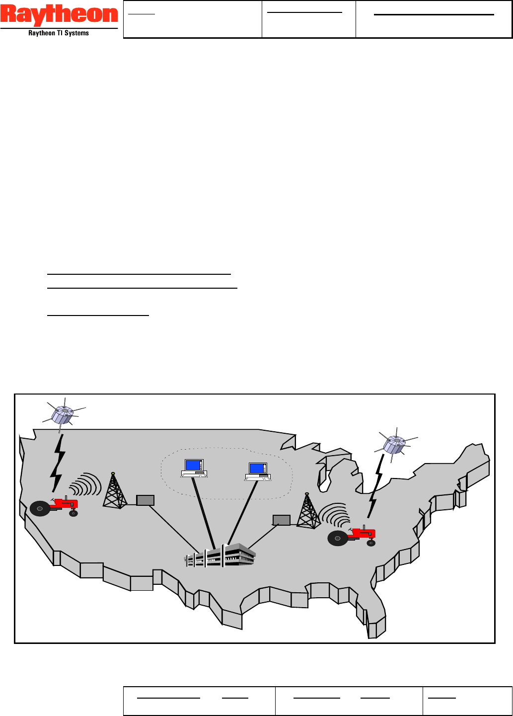
The Remote Asset Visibility (RAV) System provides a reliable, low cost communications
network for tracking assets that are transient in nature and could be anywhere in North
America. The RAV system allows customers to automatically receive communications from
their assets at predetermined times of the day at a price making it affordable to implement
on multiple assets. The system employs Global Positioning Satellite (GPS) information to
determine an asset’s location; digital processing for system control and status signal
monitoring; and a Cellular Modem for two-way communication. The position and status
information is reported to the owner of the asset and, the owner is able to send setup and
control commands back to the monitoring equipment.
4.1.1 RAV System Description.
As shown in Figure 4.1-1, the RAV System is comprised of 3 major segments:
1. CELL-TRAC™ II with Battery Pack - installed on the remote asset.
2. Raytheon TI Systems Data Center (Data Center) - for processing asset location and
status information
3. Customer Interface - to interrogate the Data Center for asset information.
The CELL-TRAC™ II is a small electronics assembly installed in a concealed or in-obvious
location on the asset. A separate battery pack is included to power the CELL-TRAC™ II
when asset power is not available. Based on a programmable schedule, the CELL-
TRAC™ II collects GPS measurements and asset status signals then stores the data into
PSTN
PSTN
Remote Users
Raytheon Systems
Data Center
GPS
Satellite
Remote Asset
Cellular
Tower
Figure 4.1-1. The RAV System.
TITLE: CELL-TRAC™ II
User’s Manual
DOCUMENT NO: Raytheon Proprietary
Protect from unauthorized use, disclosure or release in
accordance with signed Non Disclosure Agreement
ORIGINATOR DATE REVISION DATE PAGE
8OF 27
its memory. Also on a schedule, CELL-TRAC™ II places a call to the Data Center and
delivers all the stored data. A ‘polling’ mode of operation (a cellular call placed by the Data
Center to the CELL-TRAC™ II) is available for querying the CELL-TRAC™ II status and
data. The reporting process can be re-configured by downloading new CELL-TRAC™ II
setup parameters from the Data Center. Asset owners are able to access the information in
the Data Center by either an Internet or direct dial-up connection to review asset status and
location data that the CELL-TRAC™ II has collected. Internet interface screens also allow
the owners to modify parameters controlling the CELL-TRAC™ II data collection operations.
4.2 CELL-TRAC™ II Description.
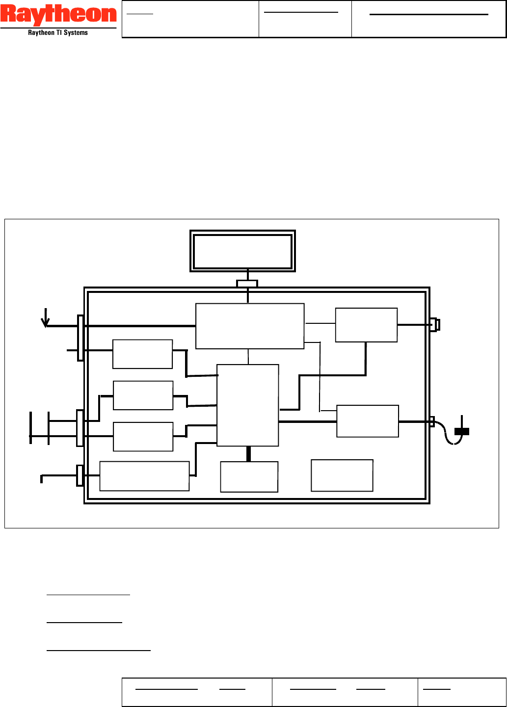
The CELL-TRAC™ II (and Battery Pack) block diagram, shown in Figure 4.2-1, include the
following functional elements:
• Cellular Modem - 3 Watt AMPS compatible cellular transmit/receive assembly for circuit
switched cellular data (CSCD) communication networks.
• GPS Receiver - acquires satellites; determines position, velocity and heading data; and
provides accurate GPS time to the System Processor.
• System Processors - direct CELL-TRAC™ II operation, monitor asset sensor inputs,
drive external control signals and manage power utilization.
GPS
Receiver
Power Supply
and
Power Mgmt
Real Time
Clock
Cellular
Modem
Data
Memory
Cellular
Antenna
GPS
Antenna
External
I/O
Local
Controller Port
Terminal
Device
RS-485
I/O
Meter
Controls
External
Inputs
Control
Outputs
Asset
Power
Battery Pack
System
Processor
Usage
Meter
Figure 4.2-1. CELL-TRAC™ II Block Diagram.
TITLE: CELL-TRAC™ II
User’s Manual
DOCUMENT NO: Raytheon Proprietary
Protect from unauthorized use, disclosure or release in
accordance with signed Non Disclosure Agreement
ORIGINATOR DATE REVISION DATE PAGE
9OF 27
• Real Time Clock - (RTC) provide the ability to wake-up the CELL-TRAC™ II for
scheduled events and status data collection.
• Usage Meter - a 32 bit counter for measuring the total asset operating time.
• Data Memory - stores current and prior readings from the GPS receiver and sensor
inputs /outputs as well as system setup parameters.
• External I/O - provides 8 digital input/outputs that may be configured for monitoring
external events or for controlling external devices. Also includes two dedicated, optically
isolated input lines for control of the Usage Meter counter.
• RS-485 - for connection to future custom sensor packages. Provides the hardware and
driver software for operation of a typical RS-485 port. Application layer software will be
developed as sensors are added.
• Local Control Port (LCP) - serial port for connection to a terminal device (e.g. PC,
laptop, small hand held controller, ... etc) to allow installation or maintenance staff to
monitor and control the CELL-TRAC™ II.
• Antennas - fast attach (typically magnetic) GPS and cellular antennae external to the
CELL-TRAC™ II package.
• Power Supply - includes connectors, regulators and monitoring circuitry to allow the
CELL-TRAC™ II to operate from asset power when available or from the Battery Pack
when asset power is not available.
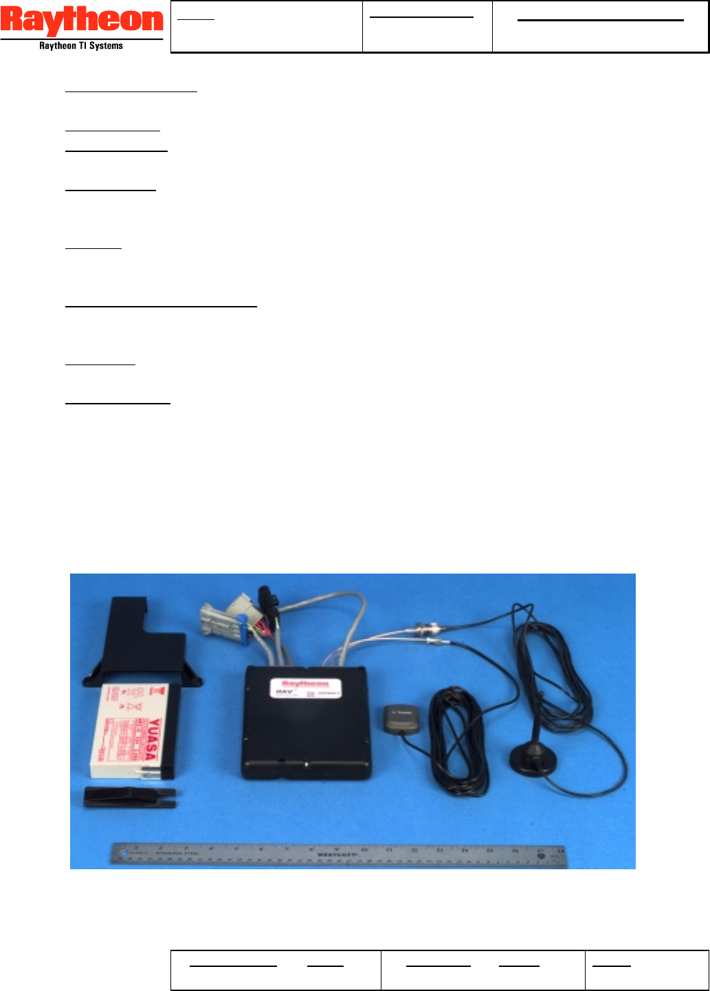
The CELL-TRAC™ II is housed in a single ruggedized package (see Figure 4.2-2). There
are no switches, buttons, dials, indicators or other displays that would indicate the existence
of sophisticated electronic capabilities. The case is mountable in such a manner as to
minimize detection by the casual observer. Also, the mounting approach supports quick
removal and re-installation on another asset.
4.2.1 Operating Modes
Figure 4.2-2. CELL-TRAC™ II Physical Characteristics.

TITLE: CELL-TRAC™ II
User’s Manual
DOCUMENT NO: Raytheon Proprietary
Protect from unauthorized use, disclosure or release in
accordance with signed Non Disclosure Agreement
ORIGINATOR DATE REVISION DATE PAGE
10 OF 27
The CELL-TRAC™ II provides 3 modes of operation:
1. Standby - Low Battery, only the RTC function is powered up.
2. Power Save – Only processes scheduled event(s) or responds to interrupts.
3. Continuous – Status monitoring and data collection continuously operating.
4.2.1.1 Standby Mode.
Lowest power mode of operation. The power supply charger function is off and only the
RTC function is operational. Average current drain on the Battery Pack does not exceed
400 µamps. There is intermittent operation, up to 12 mamps, in order to monitor battery
voltages with A/D converters. Intervals between such monitoring events shall not be less
than 30 seconds and shall not last longer than 2 seconds.
If the Battery discharges below 6.5 Vdc, the CELL-TRAC™ II will draw its power from the
Asset (without using the charger). When operating only from Asset Power, the unit is not
allowed to leave Standby mode. Entry into Standby is triggered by 3 events:
1. Connection of either the Battery Pack or Asset Power without the Battery Pack. This is
the initial power up condition.
2. Insufficient Asset Power to operate the charger and the average Battery Pack voltage
drops below a preset threshold (programmable from the Data Center, default 10.5 Vdc).
3. Disconnecting the Battery Pack while Asset Power is still available.
Transition from Standby to either the Power Save or Continuous modes is allowed only
when the average Battery Pack voltage exceeds a minimum threshold (programmable from
the Data Center, default 11.0 Vdc). This will occur if:
1. The Battery Pack is replaced.
2. Asset Power is sufficient to operate the charger function (refer to section 4.2.8.11) and
the Battery Pack recharges to the minimum threshold. Until the Battery reaches this
charge condition, the CELL-TRAC™ II will remain in the Standby mode.
4.2.1.2 Continuous Mode.
When the Usage Meter is enabled (i.e. the Asset is operating), CELL-TRAC™ II will be in
the Continuous Mode of operation. All functions will be powered. The charger for the
Battery Pack is enabled and the Usage Meter is updated on a 6 second interval. All
scheduling, I/O monitoring and exception detection functions are operational. Transition out
of Continuous mode occurs when the Usage Meter Enables become inactive or the
charger circuit is turned off. Charger turn-off occurs when Asset Power drops below a
minimum voltage (programmable from the Data Center, default 12.5 Vdc).
4.2.1.3 Power Save Mode.
Reduced power mode. If the unit is not operating (i.e. Usage Meter not enabled) the CELL-
TRAC™ II enters one of two sub modes:
1. Sleep – Similar to Standby except the Scheduler function and all external interrupt
capabilities are enabled. Average current is the same as for the Standby mode.

TITLE: CELL-TRAC™ II
User’s Manual
DOCUMENT NO: Raytheon Proprietary
Protect from unauthorized use, disclosure or release in
accordance with signed Non Disclosure Agreement
ORIGINATOR DATE REVISION DATE PAGE
11 OF 27
2. Active – One or both the GPS and Cellular functions are powered up in response to a
scheduled event. In this sub-mode, the Battery Pack average current drain depends on
the functions that are powered up and the frequency of the scheduled events.
While in Power Save the Battery charger will remain on if the Asset Power is greater than
the minimum threshold (described above). Transition from Power Save to Continuous
mode occurs when the battery charger function is enabled and the Meter Enables become
active. Transition from Power Save to Standby mode occurs when the Battery Pack
discharges below a preset threshold (programmable by the Data Center, default 10.5 Vdc).
While in Sleep, the Processor will continue to monitor the Scheduler function to determine
when an event should occur. Interrupts are enabled to allow external sources to ‘wake up’
the system and respond to the external event. This transitions the CELL-TRAC™ II from
Sleep to Active in order to process the interrupt. Once the interrupt has been serviced, the
CELL-TRAC™ II will return to Sleep.
4.2.2 Communications
The CELL-TRAC™ II supports Circuit Switched Cellular Data (CSCD) as the preferred
communication path. However, future versions of the unit will support newer wireless
communication techniques, as they become available and cost effective.
CELL-TRAC™ II always attempts to place a call to the Data Center using our primary
service provider or it's associates. To do this, CELL-TRAC™ II keeps a 'Preferred SID'
table for each service area and places all calls using the 'A Preferred' or 'B Preferred'
operating modes. In the event of errors, the preferred SID will be tried twice before the
other SID (A or B) is attempted.
4.2.2.1 Communication Protocols
Communications between the CELL-TRAC™ II and the Data Center is implemented as
follows:
• Fixed 1200 Baud with a standard handshake protocol.
• No error correction or data encryption codes.
• Utilize 16 bit CRC for error detection.
• Full binary messaging a packet data based interface.
• Provides at least 100 msec break between each message packet.
Positive acknowledgment handshakes are used to insure each message is delivered.
CELL-TRAC™ II places calls to the Data Center for the following reasons:
• Call Back – response to a ‘Polling’ call received from the Data Center.
• Exception – notification that a non-standard operating condition has been detected.
• Check-in – scheduled call to deliver collected position and status data.
• Registration – initial call to register the unit with the Data Center.
• Reset – notification that the unit has had power cycled or has been restarted.
• Blackout – unscheduled call that has been delayed by a communication blackout.
Once a call is established, the CELL-TRAC™ II delivers the data associated with the call
and then waits for new instructions or setups. The Data Center utilizes the open channel to

TITLE: CELL-TRAC™ II
User’s Manual
DOCUMENT NO: Raytheon Proprietary
Protect from unauthorized use, disclosure or release in
accordance with signed Non Disclosure Agreement
ORIGINATOR DATE REVISION DATE PAGE
12 OF 27
deliver any setup parameters, commands, or requests for information (queries) to the
CELL-TRAC™ II. The sequence is:
1. The CELL-TRAC™ II originates a call, establishes connection, and transmits the
identifier and the first ‘stored’ message in its data memory. That message repeats until
the Data Center acknowledges it, then, the CELL-TRAC™ II will delete it and send the
next message in its memory.
2. Once all stored messages have been sent and acknowledged, the CELL-TRAC™ II
notifies the Data Center that it is done and, at that point, the Data Center begins sending
any entries that it may have for that CELL-TRAC™ II unit. Each message repeats until
the CELL-TRAC™ II acknowledges and, when complete, the Data Center tells the unit
to hang-up.
3. If a ‘query’ (special request for information) is specified in a message from the Data
Center, the CELL-TRAC™ II will process the query and send the result to the Data
Center. All queries must receive a response from the CELL-TRAC™ II before the call
terminates.
4. If repeated errors prevent a successful message transmission, the CELL-TRAC™ II
disconnects then retries as described in the next section.
4.2.2.2 Call Error Handling
CELL-TRAC™ II handles the following classes of communication errors:
• No Coverage – unable to register with any SID.
• No Channel – voice channel not available from SID.
• Dropped Call – call broken during hand-off.
• No Answer – continuous ringing.
• Busy – busy signal detected.
• No Sync – failed to synchronize the modem.
• No Handshake – failed message protocol.
• CRC Error – excessive packet errors.
• Time Out – abnormal termination.
4.2.2.2.1 Call Failure Processing.
The reason for a failed communication is counted and logged for reporting to the Data
Center on the next successful communication. Error handling varies depending on the
phase of the call:
1. Cellular Connections - Failures to acquire a voice channel on the preferred SID follows
standard AMPS error processing (e.g. retry several times then return a ‘no channel’
status). CELL-TRAC™ II logs the failure and retries the connection using the preferred
SID. If the 2nd try also fails, CELL-TRAC™ II will try twice using the other SID (A or B).
If, after those 2 tries, a cellular connection cannot be established, a 'communication
blackout' condition is declared.
2. Data Center Connection – Failures occurring after a cellular connection has been
established is logged then a ‘communication blackout’ condition is declared. Processing
is as defined in the following sections.
4.2.2.2.2 ‘Communication Blackout’ Processing
If the Asset is operating (i.e. ‘Continuous’ mode in effect), CELL-TRAC™ II will continually
attempt to register with the SID. When successful, an immediate call to the Data Center is

TITLE: CELL-TRAC™ II
User’s Manual
DOCUMENT NO: Raytheon Proprietary
Protect from unauthorized use, disclosure or release in
accordance with signed Non Disclosure Agreement
ORIGINATOR DATE REVISION DATE PAGE
13 OF 27
attempted. If a Data Center connection failure occurs, the CELL-TRAC™ II will log the
results, delay up to 5 minutes (default 1 minute) and repeat the call attempt. Actual delay
values are specified by parameters from the Data Center.
If the Asset is not running (i.e. ‘Power Save’ mode in effect), a call is scheduled at the
‘blackout’ processing rate specified by the Data Center. To conserve power, the processing
rate is also ‘faded’ with Battery capacity. In either case, once a call is successfully
completed to the Data Center, the ‘communication blackout’ condition is cleared and normal
operations resumed.
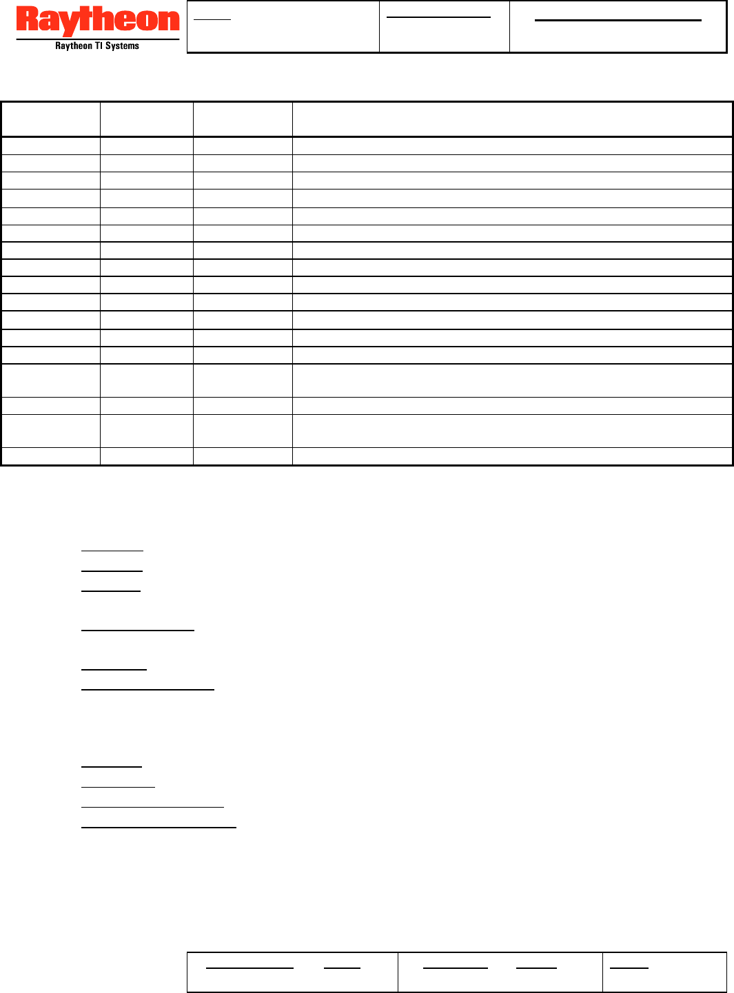
4.2.2.3 Message Definitions
The messaging capability is based on a packet data interface (PDI) protocol. A basic list of
the information that can be communicated between CELL-TRAC™ II and the Data Center
is shown in Table 4.2.3-1.
4.2.3 Processing Functions
CELL-TRAC™ II Processing functions provide for collecting data (i.e. location, usage and
status); listening for calls from the Data Center; detecting unusual conditions ( or
exceptions); and making cellular calls to the Data Center for data reporting. Two types of
control mechanisms are used:
• Scheduled Events – execute a specific function based on GPS time of week.
Scheduling parameters are provided by the Data Center. A minimal list of scheduled
events is provided in section Scheduled Events
• Exceptions – monitor, detect and respond to predefined conditions or events as
specified by the Data Center. Section 4.2.3.3 identifies (by functional element) the set
of exceptions supported.
4.2.3.1 Data Storage
For data collection and reporting functions, the CELL-TRAC™ II provides two types of data
storage mechanisms:
• Current Value – global memory containing the most recent data from a scheduled event
(i.e. location, usage, status, … etc). Each time a scheduled event is executed, the data
in the associated ‘Current Value’ memory is updated
• Send Data Queue – memory used to store messages for transmittal to the Data Center
during a Check-in event. Messages are assembled from the ‘Current Value’ memories
and placed into this queue with a GMT time stamp for the time the message is
assembled. Queue size is adequate for storing up to 50 data messages of at least 40
bytes per message.
The CELL-TRAC™ II Processor function can monitor and control the ‘Send Data’ queue
status, via parameters from the Data Center including:
• Stop on Full – Do not attempt to store any additional messages.
• Send on Full – Schedule immediate Check-in when the queue is full (Default).
• Send on ¾ Full – Schedule immediate Check-in when the queue is ¾ full.
• Send on ½ Full – Schedule immediate Check-in when the queue is ½ full.
• Report Status – Report the current status of the queue to the Data Center.
TITLE: CELL-TRAC™ II
User’s Manual
DOCUMENT NO: Raytheon Proprietary
Protect from unauthorized use, disclosure or release in
accordance with signed Non Disclosure Agreement
ORIGINATOR DATE REVISION DATE PAGE
14 OF 27
Table 4.2.3-1. Data Center and CELL-TRAC™ II Basic Information
Category Data Center CELL-
TRAC™ II Description
Packet Error Report Report Unrecognized message type received from CELL-TRAC™ II
Position Set - Data to initialize the GPS function
Query Report GPS Fix data (time, position, velocity, and fix status)
Status Query Report Connection status and error logging data
Query Report Ext I/O, Asset & Battery voltages, RSSI, Temperature, Meter Reading
Query Report CELL-TRAC™ II Status (GPS, Cell Modem, Processors)
Query Report Firmware and Hardware version numbers
Query Report Diagnostic Results
Configuration Set/Query Report Call Setup (Dial String, Check-in, Ears On, Fade, Blackout)
Set/Query Report Asset ID (AID) and Mobile Identification Number (MIN)
Query Report Cell Phone Electronic Serial Number (ESN)
Set/Query Report Scheduling (Ears On, Check-in, Exceptions, External I/O, Data Collection)
Set/Query Report Report Definition (Message list and sequence)
Set/Query Report Exception Setup (voltage thresholds, time windows, post detection response,
transient/latch, constraint regions, post detection monitor rates)
Miscellaneous Set Set End Of Transmission
Send Send Text Message to and from the Local Controller Port on the CELL-TRAC™
II
Update Send Report Status Program the AMU with new application code.
4.2.3.2 Scheduled Events
CELL-TRAC™ II supports the following set of scheduled events:
• GPS Fix – Read and Store GPS Data.
• Ears On – Wakeup and Listen for a Call From the Data Center.
• EXT I/O – Read and Store External I/O Data and both Asset Power and Battery Voltage
Levels.
• Data Collection – Build Messages from Specified ‘Current Value’ Memories and Place in
the ‘Send Data’ Queue.
• Check-in – Call Data Center and Transmit All Data in the ‘Send Data’ Queue.
• Exception Monitor – Check Parameters and Data for Pre-Defined Conditions.
Up to 32 independent and simultaneous GMT referenced events are supported. Data
Center supplied parameters provide for four types of schedules:
• Discrete – up to 30 discrete event times.
• Repetitive –start time, repeat interval and total repeat count.
• Discrete + Duration – same as Discrete but includes a duration for each event.
• Repetitive + Duration – adds duration to a Repetitive type schedule.
Definition for each of the scheduled event types is provided in the following paragraphs.
4.2.3.2.1 GPS Fix.
The GPS Receiver is powered up and queried for a position fix. The resulting data is stored
in the GPS Fix ‘Current Value’ and the CELL-TRAC™ II then synchronizes its internal clock
with the GPS time in the fix data. To minimize the effect of the intentional degradation of

TITLE: CELL-TRAC™ II
User’s Manual
DOCUMENT NO: Raytheon Proprietary
Protect from unauthorized use, disclosure or release in
accordance with signed Non Disclosure Agreement
ORIGINATOR DATE REVISION DATE PAGE
15 OF 27
GPS data by the government, up to 10 (default 5) consecutive, valid readings are averaged
for each GPS Fix.
If the GPS Receiver cannot generate a valid ‘average’ fix, a ‘GPS blackout' condition is
declared (refer to the next section). Position information is not modified in the GPS Fix
‘Current Value’ memory. However, a separate ‘GPS Fix Status’ flag is updated to indicate
the latest attempt yielded no fix.
4.2.3.2.1.1 GPS Blackout.
When a 'GPS Blackout' condition is in effect, the CELL-TRAC™ II adjusts the GPS Fix
Event schedule to look for valid GPS data. If the Continuous mode is in effect, the GPS
Received is continuously monitored for GPS coverage. When found, the CELL-TRAC™ II
will process the data and regress to the normal GPS Fix Event scheduling.
If Continuous mode is not in effect (i.e. Power Save mode), the CELL-TRAC™ II will modify
the GPS Fix Event schedule based on a ‘GPS Blackout’ search rate specified by setup
parameters from the Data Center. This rate will be in effect until valid GPS data is found.
To conserve power in this mode, the Data Center specifies ‘Fading’ (refer to section
4.2.3.2.7) parameters to limit the minimum time between GPS Fix events.
4.2.3.2.2 Ears On.
The Cellular Modem Receiver powers up and registers with the cellular network to listen for
a call originating from the Data Center. If attempts to register with the network fail, a 'no
service' condition is declared and ‘Communication blackout’ processing is activated.
For security purposes, if a call is received during the Ears On period, only two messages
types are processed: (1) "call home now"; and (2) "call the default number". Any other
message or a non-PDI communication will cause the CELL-TRAC™ II to hang up and
ignore the call. If either of the two messages is correctly received, CELL-TRAC™ II hangs
up then schedules an immediate Check-in event.
4.2.3.2.3 Ext I/O Read.
The System Processor powers up to read and store External Input values into EXT I/O
‘Current Value’ memory. This includes the 8 programmable, bi-directional I/O lines and the
Meter Enable signals. As specified by the Data Center, 8 readings are taken and compared
for consistency prior to saving the results in the ‘Current Value’ memories. Future capability
will include monitoring and storing the RS-485 and LCP inputs.
Also, this event averages 16 measurements of the Asset Power and Battery Pack voltages.
These averages are stored in the ‘Current Value’ memories for Asset Power and Battery,
respectively.
4.2.3.2.4 Data Collection.
CELL-TRAC™ II allows multiple data collection events with a single Check-in event to
support ‘Batch’ mode operations. A separate data collection schedule is provided to
assemble messages from the ‘Current Value’ memories then store them into the ‘Send
Data’ queue as defined by the Data Center (refer to ‘report setup message’ in section

TITLE: CELL-TRAC™ II
User’s Manual
DOCUMENT NO: Raytheon Proprietary
Protect from unauthorized use, disclosure or release in
accordance with signed Non Disclosure Agreement
ORIGINATOR DATE REVISION DATE PAGE
16 OF 27
4.2.3.4). When the Data Collection event occurs, each of the selected messages is
assembled then stored in the ‘Send Data’ queue along with a GMT based time stamp.
4.2.3.2.5 Check-in.
At the scheduled time, a Check-in event is executed to place a call to the Data Center. Two
types of Check-ins are provided:
• Immediate – a unique ‘report’ (as defined by the Data Center) generated and delivered
to the Data Center. An immediate Data Collection Event is initiated to assemble the
required messages and place them at the front of the ‘Send Data’ queue with a GPS
time stamp. The queue is then transmitted as for the Stored type described below.
• Stored - deliver all the messages currently stored in the "Send Data" queue. After each
message has been successfully acknowledged by the Data Center, it is deleted from the
queue.
If the call is not successfully completed for any reason, all undelivered messages in the
queue are left unchanged and a 'communication blackout' condition is declared. If the call
is successful, the ‘Send Data’ queue will be emptied.
4.2.3.2.6 Exception Monitor.
This Event causes the CELL-TRAC™ II to evaluate a set of predefined Exception Detectors
that have been selected by the Data Center. Unlike the previous events that are basically
data collection operations, this event monitors system parameters to detect exceptions to
normal operation. Setup messages from the Data Center define which exceptions are
enabled; the schedule for monitoring; and the actions to be taken when an exception is
detected.
4.2.3.2.6.1 Post Detection Response
As defined by the Data Center, CELL-TRAC™ II responds to a detected exception in one of
the following manners:
• Log – update and time stamp the appropriate ‘Current Value’.
• Report – Log the occurrence then assemble a specified exception report message in
the ‘Send Data’ queue with a GPS time stamp.
• Notify – Log, Report and schedule an immediate Check-in event.
4.2.3.2.6.2 Post Detection Operation
As setup by parameters from the Data Center, the CELL-TRAC™ II treats the detected
condition in one of the following two ways:
• Transient – a one time occurrence after which CELL-TRAC™ II resumes Exception
Monitoring as previously defined. Response to subsequent detections is the same as
for the first one.
• Latched – hold the detection until cleared by the Data Center. Adapts the monitoring
schedule to increase or decrease the frequency of monitoring. Setup parameters for the
exception identify a ‘pre-detection’ and ‘post-detection’ (or latched detection) schedule.
Latched detections will not clear when the condition clears and response to this
condition, is limited to logging the occurrences until the Data Center clears the latch.
4.2.3.2.7 Schedule Fading
TITLE: CELL-TRAC™ II
User’s Manual
DOCUMENT NO: Raytheon Proprietary
Protect from unauthorized use, disclosure or release in
accordance with signed Non Disclosure Agreement
ORIGINATOR DATE REVISION DATE PAGE
17 OF 27
Fading limits the minimum schedule interval for an event, based on the remaining Battery
Pack capacity. Battery capacity is estimated as a function of:
Battery Capacity = f(Tbatt, Vchg, Vsleep, Vactive)
where: Vsleep = average battery voltage during sleep
Vactive = average voltage during active mode
Vchg = average voltage of fully charged battery
Tbatt = average temperature of the battery
Fading allows the CELL-TRAC™ II to operate for extended periods of time between
recharges from the Asset Power.
4.2.3.3 Exceptions
System status variables and ‘Current Value’ data is monitored for pre-defined conditions
that represent exceptions to normal operation of the CELL-TRAC™ II or the Asset. CELL-
TRAC™ II supports the following exceptions for each of the functions:
• GPS Receiver
Antenna Fault – Detect a Disconnected GPS Antenna.
Constraint Region – Asset Movement ‘Out Of’ or ‘In To’ a Specific Area.
• Power Supply
Asset Power – Disconnected, Reconnected, or Asset Voltage too Low,
Battery Pack – Battery Approaching the Discharged State.
• External I/O
I/O Pattern Match – Specific Trigger Pattern on 8 I/O Lines.
LPC – Character Available on the Local Controller Port Serial Lines.
RS-485 – Character Available on the RS-485 Serial Lines.
Meter Enable – Pattern Match on the Meter Enable Lines.
For each exception, the Data Center defines a time window that the exception is active.
Other messages allow the Data Center to query the status of each Exception Detector.
When an exception is detected, up to 8 more reading are taken to verify that the condition is
valid and not just a noise spike. If it exists for the required number of consecutive samples,
the detection information is stored in data memory as the ‘Current Value’ for that exception.
CELL-TRAC™ II then begins operating in the ‘post detection’ mode identified for that
exception.
After examining each active exception detector, CELL-TRAC™ II checks for one or more
exceptions having been detected that also had a Notify response enabled. If so, an
immediate Check-in event is scheduled. The following paragraphs define each of the
exception detectors available with the CELL-TRAC™ II.
4.2.3.3.1 GPS Exceptions.
4.2.3.3.1.1 Antenna Fault
Monitors the GPS status data for an 'antenna fault' indicating the GPS antenna has been
disconnected or damaged.
TITLE: CELL-TRAC™ II
User’s Manual
DOCUMENT NO: Raytheon Proprietary
Protect from unauthorized use, disclosure or release in
accordance with signed Non Disclosure Agreement
ORIGINATOR DATE REVISION DATE PAGE
18 OF 27
4.2.3.3.1.2 Constraint Region
Monitors the ‘average’ GPS position information to define when the asset is moving or has
moved relative to a reference region. Two types of checks are supported: (1) movement
outside of a specific area and (2) movement inside of a specific area. Definition of the
region of interest is provided by the Data Center and includes:
• Origin - Lat, Long of reference point for the region of interest
• Type - Box with Origin at lower right corner or a Circle centered on Origin.
• Dimension #1 - Width if Box and Radius if Circle type.
• Dimension #2 - Length if Box and not used if Circle type.
• Mode - Detection if GPS Position Outside or Inside.
Each time the Exception Monitor processes the constraint region, the average GPS position
data is evaluated for the desired inside or outside the region condition.
4.2.3.3.2 Power Supply Exceptions.
4.2.3.3.2.1 Asset Power Monitor
Monitors the average Asset Power voltage for two conditions: (1) voltage below a set
threshold indicating a discharged Asset battery; and (2) the voltage less than 2 volts
indicating an open connection. Threshold for a discharged Asset battery is set by the Data
Center.
4.2.3.3.2.2 Battery Monitor.
Monitors the average Battery Pack voltage for a discharged state based on a threshold
voltage that is set by the Data Center.
4.2.3.3.3 External I/O Exceptions.
4.2.3.3.3.1 I/O Pattern Match Monitor.
Monitors the 8 External I/O pins for specific patterns of active and inactive lines. Mask
parameters supplied by the Data Center define which of the lines are involved; the active
states for each line; the AND / OR function associating the lines; and the specific pattern
desired.
4.2.3.3.3.2 LPC Monitor.
Monitors the LPC serial line for the presence of an input character. If found, the results are
entered into the LPC Status ‘Current Value’ and the LPC service program is started.
4.2.3.3.3.3 RS-485 Monitor.
Monitors the RS-485 serial lines for the presence of an input character. If found, the
characters are entered into the RS-485 ‘Current Value’ and the service program is started.
4.2.3.3.3.4 Meter Enable Monitor.
Monitors the two meter enable lines for a specific pattern. Mask parameters supplied by the
Data Center define which of the two lines are involved; the active states for each line; the
AND / OR function associating the lines; and the specific pattern desired.
4.2.3.4 Check-in Reports

TITLE: CELL-TRAC™ II
User’s Manual
DOCUMENT NO: Raytheon Proprietary
Protect from unauthorized use, disclosure or release in
accordance with signed Non Disclosure Agreement
ORIGINATOR DATE REVISION DATE PAGE
19 OF 27
Content of the information or data delivered to the Data Center with each Check-in Event is
fully configurable by parameters from the Data Center. A sequenced list of PDI messages
is defined for each Data Collection, Immediate Check-in or Exception detection operation.
4.2.4 Software Updates.
CELL-TRAC™ II supports software updates by loading new code from a computer attached
to the LCP or ‘over-the-air’ using the cellular network. In the event of a broken
communication session, CELL-TRAC™ II tracks and reports the last good code packet
downloaded then resume loading at the next one. After new code has completely
downloaded, CELL-TRAC™ II reboots and attempts an immediate call to the Data Center
to verify the load was successful.
If the call is successful, the Data Center instructs the CELL-TRAC™ II to make the change
permanent. If the call fails for any reason, the CELL-TRAC™ II will revert to the original
code then, at the next successful regular Check-in, notifies the Data Center of the failure to
load and execute the new code.
4.2.5 Delivered Configuration
The CELL-TRAC™ II is delivered as a complete package including:
1. CELL-TRAC™ II Assembly ... housing and mounting hardware.
2. Battery ... battery cable, housing and mounting hardware.
3. Installation Cable Hardware ... mating connectors and pins.
4. Antennas ... GPS and Cellular Antennas with cabling (magnetic or bulkhead).
5. Manuals and printed literature ... installation and operators manuals.
All installation dependent cables, fuses and hardware are the customer’s responsibility.
4.2.5.1 Shipping Considerations
The Battery may or may not be included in the shipment from the factory, based on
transportation limitations or logistics issues.
4.2.5.2 Cellular Registration and Activation
Assignment of the Mobile Identification Number (MIN) occurs at the time of installation.
When shipped from the factory, the CELL-TRAC™ II have a MIN of 0 (zero). The MIN is
pre-registered into the Cellular Network but will not be activated until the time of installation.
4.2.6 CELL-TRAC™ II Installation.
Trained personnel equipped with the proper procedures and equipment will accomplish
installation of the CELL-TRAC™ II. It may be performed either as part of an asset’s
manufacturing flow or as an after market upgrade on existing assets.
4.2.7 Asset Registration.
The RAV System requires that each CELL-TRAC™ II be associated with the asset on
which it is installed. Assigning a unique Asset Identifier (AID) to each CELL-TRAC™ II and
Asset combination accomplish this. All call-in sessions from the CELL-TRAC™ II to the
Data Center will include the AID.
TITLE: CELL-TRAC™ II
User’s Manual
DOCUMENT NO: Raytheon Proprietary
Protect from unauthorized use, disclosure or release in
accordance with signed Non Disclosure Agreement
ORIGINATOR DATE REVISION DATE PAGE
20 OF 27
4.2.7.1 Association Approach.
CELL-TRAC™ II provides memory for a 32 bit AID that is assigned by the Data Center
during the asset registration process. An AID equal to zero (0) indicates the CELL-TRAC™
II is not registered with the Data Center. After registration is successfully completed, the
AID is set equal to a unique 32 bit number.
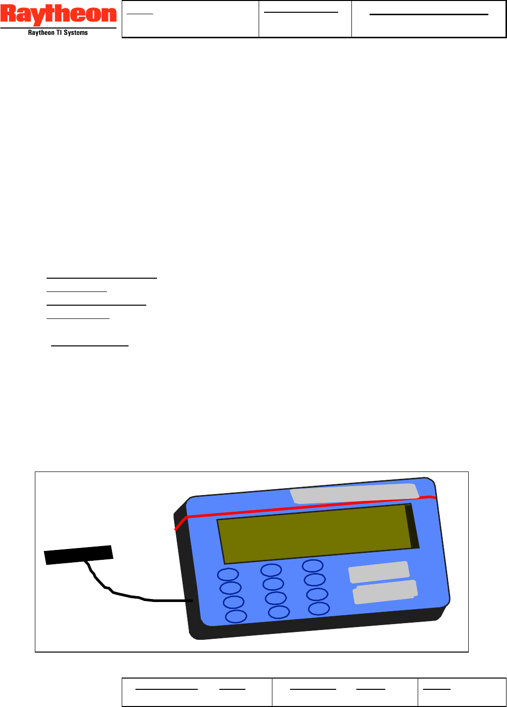
4.2.7.2 Registration Process.
During installation, a handheld computer terminal called Setup and Diagnostic System or
SDS, (Figure 4.2-3) is connected to the LCP on the CELL-TRAC™ II using a serial to RS-
232 level shifter subassembly. The Processor recognizes that the SDS has been
connected and initiates communications within 60 seconds.
4.2.7.2.1 CELL-TRAC™ II Part of Registration
The Installer selects ‘Registration’ from the SDS Menu and enters the needed registration
information. Inputs are free form containing letters, numbers or special characters. At a
minimum, the information entered will include:
1. “Company Identifier” - 5 character identifier assigned to the asset owner.
2. “Asset S/N” - owner's unique identifier for the asset (10 characters or less).
3. “Asset Description” - a textual description for the asset (32 characters or less).
4. “Field One” - optional text describing or identifying the asset's usage (e.g. model
number, job site, work assignment, foreman, etc.).
5. "Meter Reading" - an initial value for the Usage Meter.
The “Meter Reading” value is sent by the SDS to the CELL-TRAC™ II to initialize the Usage
Meter. The other parameters are saved in SDS memory for use in the registration process.
The Installer then executes predefined diagnostics (from the SDS) to verify proper
installation and that the unit is healthy. Diagnostic results are saved in SDS memory as
part of the registration information for the asset.
Registration is initiated by pressing the “Activate” key. All the asset information and
Activate
1
4
GHI
7
PRS
*
2
5
8
0
ABC
JKL
TUV
3
DEF
6
MNO
9
WXY
#Test
Raytheon SYSTEMS
Figure 4.2-3. Example of a Setup and Diagnostic System (SDS).

TITLE: CELL-TRAC™ II
User’s Manual
DOCUMENT NO: Raytheon Proprietary
Protect from unauthorized use, disclosure or release in
accordance with signed Non Disclosure Agreement
ORIGINATOR DATE REVISION DATE PAGE
21 OF 27
diagnostic results are packed into Text Messages and sent to the CELL-TRAC™ II along
with registration dialing instructions. CELL-TRAC™ II, adds the unit's MIN and ESN to
create a “Registration” message. A call is then placed to the Data Center to transmit the
messages.
If the CELL-TRAC™ II successfully completes the transmission, it is assigned a temporary
AID and supplied with information defining a time to call back to get the results of the
registration process. CELL-TRAC™ II terminates the call and posts a "Registration
Requested ... Awaiting Response" message on the SDS. While waiting, CELL-TRAC™ II
will operate in Continuous mode listening for possible calls from the Data Center.
If the call to the Data Center is not successful, a "Unable to Contact the Data Center ... try
again later" message is sent to the SDS and the CELL-TRAC™ II will return to the Standby
state awaiting further instruction from the SDS.
4.2.7.2.2 Data Center Part of Registration
When the Data Center receives the call from a CELL-TRAC™ II unit with an AID of zero (0),
it will assume the unit is applying for registration with the network. Since the unit’s
ESN/MIN is not currently active in the database, registration processing is initiated. The
Customer ID is validated and, if a valid customer account is found, the remaining
registration information is loaded into the working database. Also, the diagnostic results are
loaded in to a ‘warranty/repair’ database.
A unique AID is assembled into a "set AID" message and a "Registration Successful!"
message is generated. These messages and default setup parameters are loaded to the
unit’s 'output queue'. The Data Center places a call to the CELL-TRAC™ II to signal that
the results are waiting.
If the registration was not successful, the AID is set to zero (0) and a text message of
“Registration failed... call the Data Center!” is generated. Both the 'Set AID' and text
message is placed in the 'output queue'. As before, either the Data Center waits for the call
back or initiates a call to the CELL-TRAC™ II.
4.2.7.2.3 Registration Completion
The CELL-TRAC™ II will dial back to the Data Center to pick up the "set AID" message,
registration status message and the default parameters. All setup messages are processed
and the status message delivered to the SDS. If the AID is nonzero, the CELL-TRAC™ II
will begin operating in the appropriate Power Save or Continuous state. Otherwise, it
returns to the Standby state awaiting further input from the SDS.
4.2.8 Functional Elements
4.2.8.1 Cellular Modem.
The Cell Modem uses 3 Watt, AMPS compatible cellular transmit and receive CELL-
TRAC™ II without a display or keypad.
1. A 3 Watt Transmitter with stepped attenuation to minimize inter-cell interference.
2. Minimum of -116 dBm Receiver sensitivity at 12 dB SINAD.
3. Support DTMF transmits.

TITLE: CELL-TRAC™ II
User’s Manual
DOCUMENT NO: Raytheon Proprietary
Protect from unauthorized use, disclosure or release in
accordance with signed Non Disclosure Agreement
ORIGINATOR DATE REVISION DATE PAGE
22 OF 27
4. Support 1200 Baud data transmissions and 2400 Baud code downloads.
5. Two NAM capability, fully programmable, with at least 12 digits per NAM.
6. Access to both A and B service providers.
7. Preferred SID Table for Initiating Calls.
8. Operate from 12 Vdc.
9. Transmit (at 3 watts) max current of 1.5 amps peak with 1/12 duty cycle.
10. Receive (Ears On) operation max current of 30 mamps.
4.2.8.2 GPS Receiver.
The CELL-TRAC™ II is able to work with a GPS Receiver that meets or exceeds the
capability of the Trimble SK-8:
1. Minimum 6 channels, continuous tracking receiver.
2. Support Query mode and Auto Update at a rate of 1 per second.
3. Support standard position/velocity, differentially corrected or raw data reporting.
4. Position accuracy of 100 meter rms (typical, limited by Selective Availability).
5. Velocity accuracy of at least 1.0 m/s (2.1 mph).
6. Heading accuracy of at least 6.0 deg for velocities greater than 10 m/s (21 mph).
7. Initial Acquisition times:
• Cold start (uninitialized) < 120 seconds (90%)
• Warm start (last position, time and almanac available) < 45 seconds (90%)
• Hot start (ephemeris also saved) < 20 seconds (90%)
• Reacquisition time < 5 seconds (90%)
8. WGS-84 Datum
9. Max current of 95 mamps at 12 Vdc.
4.2.8.3 System Processors.
The System Processor includes two processor elements and provides all operational
monitoring and control functions.
1. Power Management and Control.
2. Digital Signal Processing with RS-232 for connection to the LCP.
3. Power up and Commanded BIT for diagnostics over the Cell Modem or the LCP.
4. Non-volatile memory for code/data storage.
5. Support new code upgrades via the Cell Modem or the LCP.
6. Monitor and control the 8 external input/output lines as well as RS-485 port.
7. Max combined current of 30 mamps active and 400 µamps in Sleep at 12 Vdc.
4.2.8.4 Real Time Clock (RTC).
The RTC function provides all timing oriented operation of the CELL-TRAC™ II including
scheduling of tasks, measurement of time intervals and synchronizing of call handling.
1. Operate on GMT (UTC) for all timing functions.
2. Synchronized with GPS Fix time.
3. Able to monitor Asset Power, Battery voltage, External Inputs and LCP in the lowest
power mode.
4.2.8.5 Data Memory.
Data Memory provides storage for both system parameters and asset data:
1. Flash or EEROM for code, setup parameters and collected data to insure information is
not lost during Battery replacement or discharge/recharge cycles.

TITLE: CELL-TRAC™ II
User’s Manual
DOCUMENT NO: Raytheon Proprietary
Protect from unauthorized use, disclosure or release in
accordance with signed Non Disclosure Agreement
ORIGINATOR DATE REVISION DATE PAGE
23 OF 27
2. Minimum of 32 Kbytes of code storage per processor.
3. Minimum of 1 Kbyte of data/scratch pad RAM per processor.
4. Minimum of 64 Kbytes of “download' buffer per processor for software upgrades.
5. Minimum of 128 Kbytes for the ‘send data’ queue.
6. Minimum of 1 Kbyte for a 'preferred SID' table.
4.2.8.6 Usage Meter.
An elapsed time counter or meter to measure the total operating time for the Asset. Setup
parameters from the Data Center, specify a unique pattern of External I/O and Meter
Enable lines pattern that control the active window for the Usage Meter. Exactly which lines
are involved, the AND/OR relationship and the active levels are defined by the Data Center.
The timer is enabled when the pattern is true and disabled when false. As a second
criteria, the CELL-TRAC™ II must be operating (i.e. in Continuous mode) for the Usage
Meter to run.
1. Timer is monitored under the direction of a Data Collection event.
2. Is two bytes in length and has a programmable resolution of 6 seconds.
3. Reading must be monotonic when compared to Usage Meter ‘Current Value’ memory
and the change in value must not exceed the time since the last reading.
4.2.8.7 External I/O.
Discrete input lines are provided for monitoring of external sensors that are part of the Asset
(e.g. door opening, over temp, ignition on/off, ... etc). Discrete output lines are provided for
control of selected asset elements (e.g. relays, indicators, actuators, door locks ... etc.).
1. 8 Input/output lines supporting one TTL load and internal pull-ups for open collector
signals. Inputs are protected from shorts to +28 Vdc or ground for up to 5 minutes.
2. Single ended connections are provided. Customers are responsible for conditioning
circuitry for converting the asset signals to TTL levels.
4.2.8.8 Local Control Port (LCP).
CELL-TRAC™ II includes a TTL level serial port interface to an external computer for local
access and control. The LCP supports RS-232 protocol but requires an external adapter to
convert from 0 to 5 V logic (TTL/CMOS) to the RS-232 -5V to +5 V levels.
1. Minimum of 9600 Baud, Bi-directional communication based on PDI messaging.
2. Provide signals to wake up the Processor function if a key is pressed in Sleep state.
4.2.8.9 RS-485 Port
Hardware support for a single wire RS-485 interface is included in the CELL-TRAC™ II
design. Basic driver support is incorporated into the product. Application layer software
and protocols will be added per customer request.
4.2.8.10 Antennas.
The GPS and Cellular magnetic base antennas connect to the CELL-TRAC™ II through a
minimum of 4 meters of cable for each antenna. Bulkhead mounting options are available.
4.2.8.11 Power Supply / Power Management
The Power Supply assembly includes: Asset Power interfaces; battery charger; voltage
regulators; short circuit/over voltage protections; and power management circuits.
TITLE: CELL-TRAC™ II
User’s Manual
DOCUMENT NO: Raytheon Proprietary
Protect from unauthorized use, disclosure or release in
accordance with signed Non Disclosure Agreement
ORIGINATOR DATE REVISION DATE PAGE
24 OF 27
1. Provide temperature compensated circuits for recharging the Battery Pack from the
Asset Power connections. The CELL-TRAC™ II achieves a 90% recharge of the
Battery Pack within 4 hours at 20 ºC.
2. CELL-TRAC™ II operates on +12 or +24 Vdc systems (refer to Table 4.2.8-1) without
manual selection. Additionally, the power supply will survive the over-voltage and short-
circuit conditions shown.
3. Asset Power installation cables provided by the user are required to include a 2A fast
blow fuse at the Asset’s battery. Maximum current draw from the Asset Power is < 1.0
amp when charging and < 500 µamps in the Sleep state.
4. The CELL-TRAC™ II will not charge from the Asset Power if the asset voltage drops
below a pre-set threshold (defined by the Data Center, default 12.5V). The charger
does not turn on until the Asset Power exceeds a 2nd pre-set threshold (defined by the
Data Center, default 12.8).
4.2.8.12 CELL-TRAC™ II Battery Pack
The Battery is a +12 Vdc, sealed lead acid battery rated for 2Ahr at 20ºC. Adequate
capacity is available to operate the CELL-TRAC™ II, without Asset Power, for 30 days
under the following conditions:
1. Recharge for 4 hours to a full capacity (>13.5 Vdc unloaded).
2. Reduce Asset Power below the charger cutoff threshold (default 12.5 Vdc).
3. Operating parameters set for:
• No Data Collection Events
• Ears On every 30 minutes
• GPS Fix once per day
• Check-in once per day
• Exception Monitoring 1 each minute
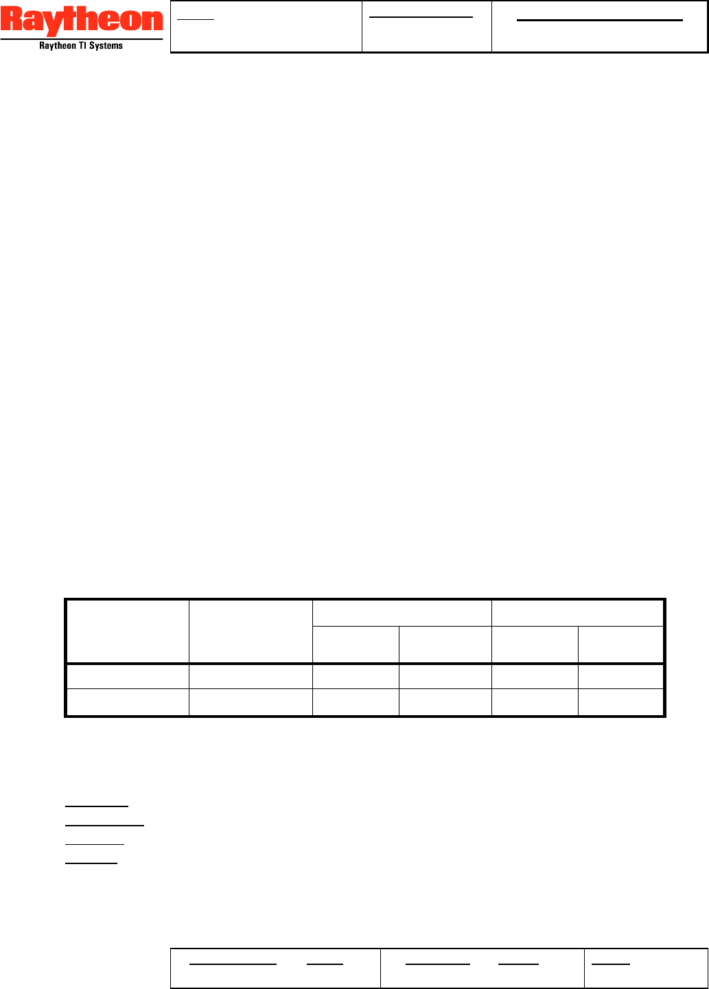
Table 4.2.8-1. Asset Supply Voltage Environment.
Chassis Operating Non Operating **
Asset Power Ground Min
(Vdc) Max
(Vdc) Reverse
(Vdc) Max
(Vdc)
+12 Vdc Neg +9.8 +18.0 -28.0 +18.0
+24 Vdc Neg +19.8 +36.0 -28.0 +36.0
** applied for 5 minutes
4.2.8.13 Cables and Connectors
Other cables and connections for CELL-TRAC™ II include:
1. POWER Cable - Asset Power (B+) and ground; Meter Enable 1 and 2.
2. LCP Serial Cable - serial interconnect for LCP.
3. EXT I/O Cable - 8 External I/O signals; and RS-485 connection.
4. Battery Cable - +12 and ground; and 2 wire thermistor connection.
All cables are 'flying lead' soldered to the circuit board and use commercially available
sheathed wire with molded grommets for sealing and strain. The POWER, LCP Serial and
TITLE: CELL-TRAC™ II
User’s Manual
DOCUMENT NO: Raytheon Proprietary
Protect from unauthorized use, disclosure or release in
accordance with signed Non Disclosure Agreement
ORIGINATOR DATE REVISION DATE PAGE
25 OF 27
Battery cables utilize 18 gauge (9130 series). The EXT I/O cable utilize 22 gage (2512
series). Connectors are as specified in the following paragraphs.
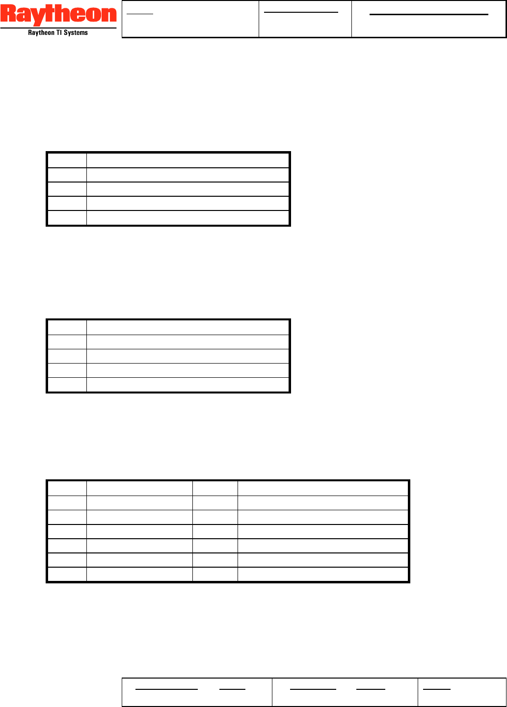
4.2.8.14 POWER Cable
The Power Cable is a Belden 8489 4 conductor 18 gage cable, terminated in a Packard
1212-9600 connector. Pin assignments are defined in Table 4.2.8-2.
Table 4.2.8-2. Power Cable Pin Assignments
Pin Signal Name
A Asset Battery (B+) **
B Asset Ground (negative)
C Meter Enable #1
D Meter Enable #2
** 2A fast blow fuse required at the asset battery.
4.2.8.15 LCP Serial Cable
The LPC Serial cable is a Belden 8489 4 conductor 18 gage cable, terminated in a Packard
1212-9600 connector. Pin assignments are defined in Table 4.2.8-3.
Table 4.2.8-3. LCP Serial Cable Pin Assignments
Pin Signal Name
A LCP Transmit
B LCP Receive
C+5 Vdc
D Ground
4.2.8.16 EXT I/O Cable
The EXT I/O cable is a Belden 8457, 12 conductor 22 gage cable, terminated in a Deutsch
DTM 04-12A connector. Pin assignments are defined in Table 4.2.8-4.
Table 4.2.8-4. EXT I/O Cable Pin Assignments
Pin Signal Name Pin Signal Name
1 I/O 1 7 I/O 7
2 I/O 2 8 I/O 8
3 I/O 3 9 RS-485 Data + (bi-directional)
4 I/O 4 10 RS-485 Data - (bi-directional)
5 I/O 5 11 +5 Vdc
6 I/O 6 12 Ground
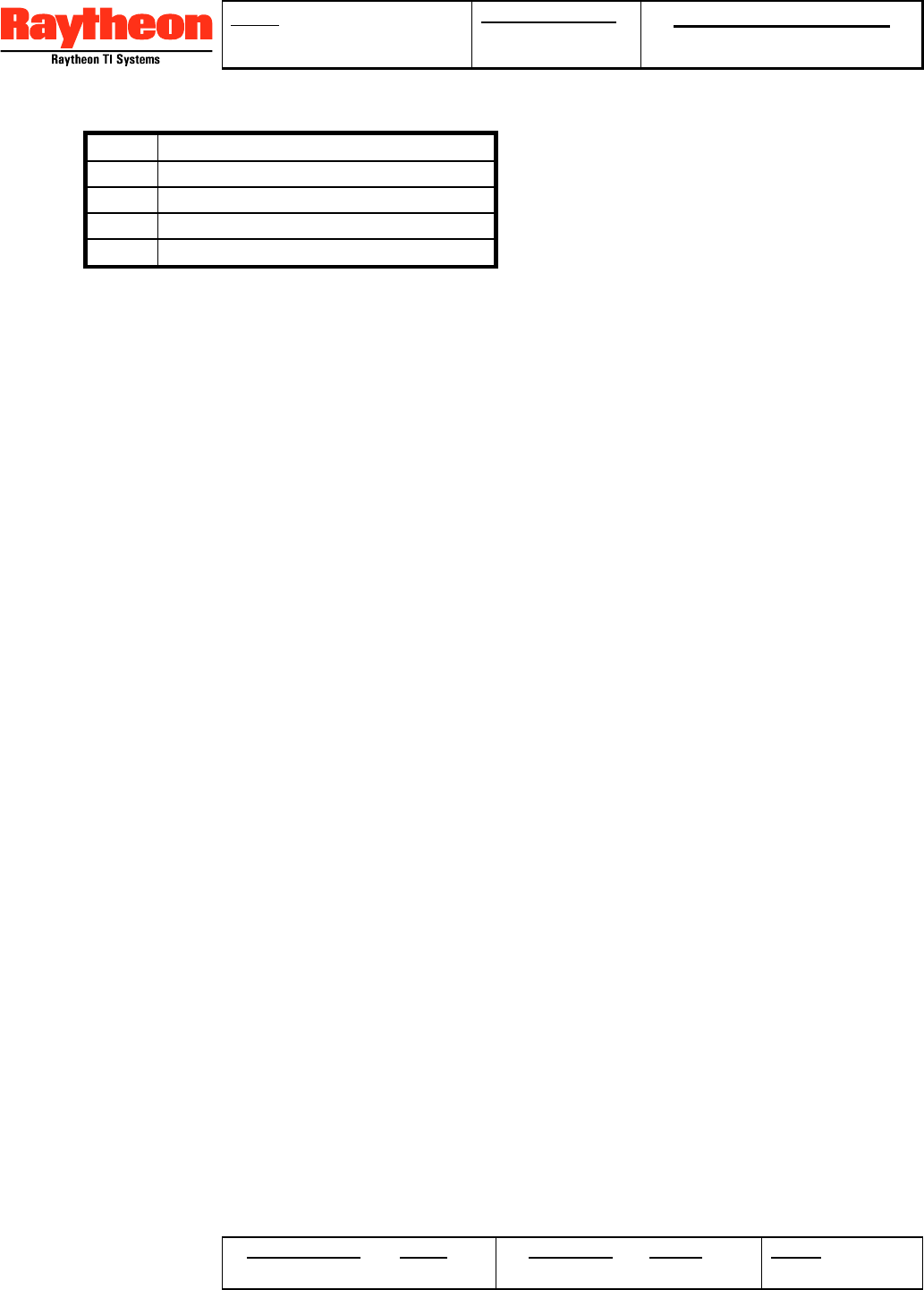
4.2.8.17 Battery Cable
The Battery Cable is a Belden 8489 4 conductor 18 gage cable, terminated in a molded
connector developed specifically for the current Battery Pack. The molded plug includes a
thermistor for monitoring the temperature of the battery and a 2A re-settable fuse to protect
the battery from damage caused by short circuits in the cable. Table 4.2.8-5 defines the pin
assignments for the molded connector.
TITLE: CELL-TRAC™ II
User’s Manual
DOCUMENT NO: Raytheon Proprietary
Protect from unauthorized use, disclosure or release in
accordance with signed Non Disclosure Agreement
ORIGINATOR DATE REVISION DATE PAGE
26 OF 27
Table 4.2.8-5. Battery Cable Pin Assignments
Pin Signal Name
A Battery +
B Battery -
C Thermistor In
D Thermistor Out
4.2.9 Diagnostics
Design of the CELL-TRAC™ II incorporates Diagnostics and BIT capabilities that are
accessible through the LCP or Over-the-air via the cellular network:
1. Power up BIT that includes checksum of all executable code; verification of data
memories; and status check for the GPS receiver and external I/O.
2. Power up BIT results are delivered to the SDS (if connected) and made available to the
Data Center upon request.
3. Extended diagnostic capabilities is available via the SDS.
4.2.10 Packaging
The CELL-TRAC™ II is contained in a plastic case enclosing all electronic subassemblies.
The battery is mounted in a separate plastic case, which can be attached to the CELL-
TRAC™ II.
• Dimensions of the CELL-TRAC™ II case is 5.25 in x 7.25 in x 1 in (l x w x h). Mounting
points are within the outline of the case (i.e. no protruding tabs).
• The case is plastic injection molded using material resistant to cracks, chips, fading,
ozone/ultra violet light exposure, chemicals, dust and moisture. The case need not be
sealed.
• The Battery has a separate case and is designed to stack on the CELL-TRAC™ II or
mount in a side-by-side configuration. No special tools or methods are required to
replace the battery.
• No On/Off switch, control knobs or displays.
• Weight is less than 2 pounds including the battery.
• Mounting points support assembly torque of 25 to 40 in-lbs.
The CELL-TRAC™ II housing and Battery case have the associated Raytheon TI Systems
part number molded into the material.
4.2.11 Product Marking
A 2” x 3” product identification label is attached to the front face of the CELL-TRAC™ II
housing. Material for the label is durable and non-fading over the life of the product. The
label includes a Remote Asset Visibility Logo and Cellular ESN. The FCC identification
label is also attached to the front face of the CELL-TRAC™ II with the appropriate FCC
approval markings. Provisions shall be made for a customer logo on units being private
labeled. Also, an overlay ‘sticky’ label carrying both the hardware and software versions as
shipped from the factory. This label will be removed at installation.
4.2.12 Operating Environment
4.2.12.1 Temperature / Humidity

TITLE: CELL-TRAC™ II
User’s Manual
DOCUMENT NO: Raytheon Proprietary
Protect from unauthorized use, disclosure or release in
accordance with signed Non Disclosure Agreement
ORIGINATOR DATE REVISION DATE PAGE
27 OF 27
The CELL-TRAC™ II and Battery is capable of meeting the following operational and
storage environmental conditions:
Continuous Operating Temperature: -34 to +72 ºC, +85 ºC peak
(Ambient on the case)
Humidity: 0% to 95%, non-condensing
Storage Temperature: -40 to +85 ºC.
4.2.13 Regulatory Compliance
The CELL-TRAC™ II is approvals per CFR 47 Part 15 and CFR 47 Part 22 by the FCC
(US) and CAN Wireless (Canada).
4.2.14 Warranty
The Supplier shall warranty the CELL-TRAC™ II for a minimum of one (1) year.