Redpine Signals RS9113DB 802.11 abgn WiFi/BT/Zigbee MODULE User Manual Lite Fi XP Test Driver Installation Guide
Redpine Signals Inc 802.11 abgn WiFi/BT/Zigbee MODULE Lite Fi XP Test Driver Installation Guide
Contents
- 1. Manual
- 2. Addition Letter
- 3. -Manual
Manual


Redpine Signals, Inc. Proprietary and Confidential
RS9113
PHY Evaluation Test Utility
User Guide for Linux
Disclaimer:
The information in this document pertains to information related to Redpine Signals,
Inc. products. This information is provided as a service to our customers, and may
be used for information purposes only.
Redpine assumes no liabilities or responsibilities for errors or omissions in this
document. This document may be changed at any time at Redpine’s sole discretion
without any prior notice to anyone. Redpine is not committed to updating these
documents in the future.
Copyright 2014 Redpine Signals, Inc. All rights reserved.

Redpine Signals, Inc. Proprietary and Confidential
RS9113
PHY Evaluation Test Utility
User Guide for Linux
Table of Contents
1 Introduction ........................................................................ 5
2 Test Setup Details ................................................................ 6
3 Transmit Tests ..................................................................... 9
3.1 Application Usage ................................................................. 9
4 Programmable PER packet ................................................. 15
4.1 Application Usage ............................................................... 15
5 Receive Tests ..................................................................... 18
5.1 Application Usage ............................................................... 18

P a g e | 4
4
Table of Figures
Figure 1: Linux Based RF Evaluation Setup With USB Interface .................. 6
Figure 2: Linux Based RF Evaluation Setup With SDIO Interface ................. 7
Figure 3: Utility Diagram .............................................................................. 7

5
Onebox-Mobile
PHY Evaluation Test Utility
User Guide for Linux
1 Introduction
The purpose of this document is to provide the usage of the applications
for transmit and receive tests to evaluate the RF performance of the
RS9113™ (RS9113) using a test driver in Linux environment.
The evaluation board provides the necessary connectors so that you can
measure transmit and receive performance of the PHY, using Spectrum
Analyzer and Signal Generator in either 2.4GHz or 5GHz (For RS9113
module).
In general, transmit performance of a radio can be analyzed in three
steps.
Maximum power: The user can observe the RF output power for a given
maximum gain supported by the RF.
EVM: The user can observe the EVM for a given rated RF power as
supported by the RF transceiver.
Spectral Mask: The user can verify whether the RS9113™ module meets
the spectral mask requirements defined by IEEE standard for a given
maximum RF output power, in a particular mode of operation like 11a,
11b, 11g etc.
The receive performance of the PHY can be analyzed using Packet Error
Ratio (PER) test.
The Rx performance is analyzed by the sensitivities at different data
rates. In general, the sensitivity is observed as 10% Packet Error Ratio
(PER) point in 11a and 11g, and 8% PER point in 11b.
The document contains two major sections.
Section 3 describes the usage of the ‘transmit’ utility, which provides the
options for setting various parameters to carry out transmit tests on the
RS9113™ device.
Section 4 describes the usage of the ‘receive’ utility, which enables the
user to perform receive tests on the RS9113™ device.
6
Onebox-Mobile
PHY Evaluation Test Utility
User Guide for Linux
2 Test Setup Details
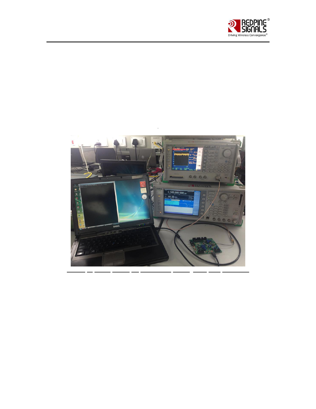
The diagram shown below, illustrates the test setup for evaluating receive
and transmit performance of RS9113™ WLAN module.
As shown in the test setup, the RS9113™ evaluation board (EVB) is
plugged into Linux based laptop either on the SDIO slot via SDIO
connector or USB port via USB cable through port J6 on the EVB. The
board is connected to a WLAN signal analyzer through a microwave
coaxial cable to test the Tx performance.
Figure 1: Linux Based RF Evaluation Setup With USB Interface
7
Onebox-Mobile
PHY Evaluation Test Utility
User Guide for Linux
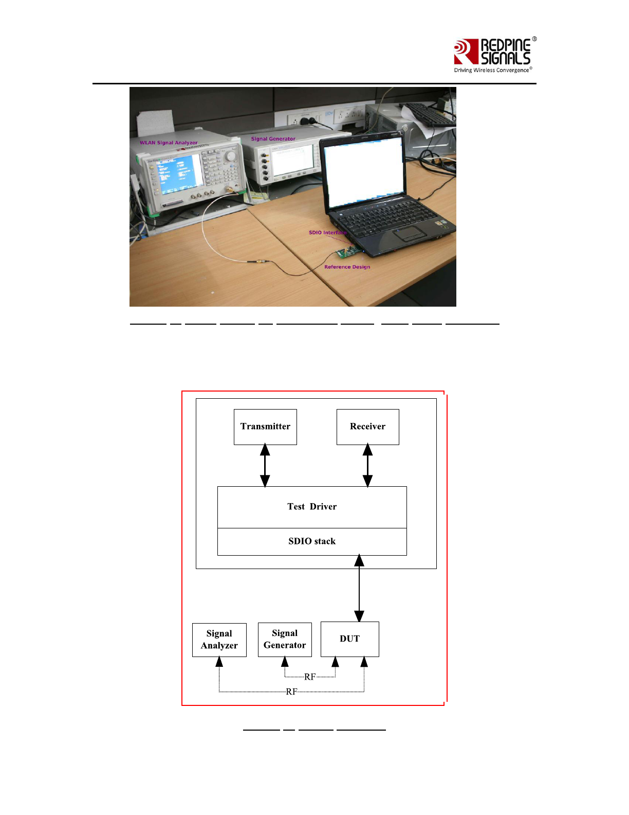
Figure 2: Linux Based RF Evaluation Setup With SDIO Interface
Following diagram illustrates various software components involved in
performing Tx and Rx tests using spectrum analyzer and signal generator
respectively.
Figure 3: Utility Diagram

8
Onebox-Mobile
PHY Evaluation Test Utility
User Guide for Linux
The ‘transmit’ utility is a command line application to perform Tx tests.
Before running the Tx tests, the user is expected to connect RS9113™ to
a signal analyzer using the RF cable.
The ‘receive’ utility is also a separate command line application that can
be used for displaying statistics on the received packets while carrying
out the receive sensitivity tests.
Please follow “RS9113-SW-Installation-Guide” for building and installing
the RS9113™ driver.
To configure the driver in “PER” Mode make sure to have the following
line in “release/insert.sh”.
DRIVER_MODE = 2
After the card has been detected successfully (issue “dmesg –c” in
terminal to check the status for the USB card it will show “new high-
speed USB device detection” while for the SDIO it will show “new High
speed SDIO card detected”) the Tx and Rx tests can be started. Please
follow the subsequent sections for executing the Tx and Rx tests.
When driver is compiled in “host” directory driver would be using binaries
from “release”.
If there are any modifications in “host” directory then driver compilation
is required.
The RS9113 driver offers two main modes of operation:
1. End-end, or Wi-Fi mode
2. PER mode for PHY evaluation
To configure the driver in Wi-Fi or (END-to-END) Mode make sure to have
the following line in “release/insert.sh”.
DRIVER_MODE = 1
In order to configure the driver in PHY Evaluation mode (PER mode) then
make sure the “DRIVER_MODE” parameter should be set as
DRIVER_MODE = 2

9
Onebox-Mobile
PHY Evaluation Test Utility
User Guide for Linux
3 Transmit Tests
In general, before performing any tests configure the PHY to operate in
the appropriate band. The transmit tests can be performed through a
utility called ‘transmit’ which is found under ‘release’ directory.
Configure the following parameters through this application before
running the tests.
Transmit power
Transmit data rate
Packet length
Transmit mode
Channel number
External PA-Enable/Disable
Rate flags
Aggregation flag
Number of packets to send in burst mode
Delay between the packets in burst mode
3.1 Application Usage
The application can be started in the following manner:
# cd release
# ./transmit <g> <r> <l> <m><c> <p> <f> <a> <n> <d>
<g> refers to Tx gain value for controlling transmit power.
<r> refers to Tx Rate.
<l> refers to length of the Tx packet
<m> refers to Transmit mode.
0 – Burst Mode
1 – Continuous Mode
<c> refers to Channel number
<p> refers to External PA-Enable/disable
<f> refers to Short GI, Greenfield and Channel Width.
<a> refers to enable/disable aggregation
<n> refers to number of packets to send in burst mode.
<d> refers to delay between packets in burst mode.

10
Onebox-Mobile
PHY Evaluation Test Utility
User Guide for Linux
After starting this application, user has to enter the following command to
stop the ongoing transmission:
# ./transmit <m>
<m> - 0 for Burst Mode
1 for Continuous Mode
Set power value:
To set Tx gain value, enter a valid value for <p> parameter. The valid
values are from 229 to 255 for RS9113 module. The transmit power
increases proportionately with increase in Tx gain value in OFDM and CCK
modes. This support is not present in this release.
Set Data Rate:
To set transmit data rate, enter a valid rate for <r> parameter.
Valid values are (1,2,5.5,11,6,9,12,18,24,36,48,54,mcs0, mcs1, mcs2,
mcs3, mcs4, mcs5, mcs6, mcs7).
Set Packet Length:
For setting the transmission packet length, enter a valid value for <l>
parameter.
Valid values are in the range of 24 and 1500.The values are in bytes.
Set Transmit Mode:
For setting the transmission mode, you need to enter one of the following
values for <m> parameter.
1 for continuous mode
0 for burst mode.
Set Channel number:
For setting the channel number in 2.4 GHz you need to enter a value in
the range 1 –11 for <c> parameter. The following tables map the channel
number to the actual radio frequency in the 2.4 GHz spectrum for 20MHz
channel width.

11
Onebox-Mobile
PHY Evaluation Test Utility
User Guide for Linux
Table 1 Channel Number and Frequencies for 20MHz Channel Width in
2.4GHz
Channel
Numbers (2.4GHz)
Center
frequencies for
20MHz channel
width(MHz)
1
2412
2
2417
3
2422
4
2427
5
2432
6
2437
7
2442
8
2447
9
2452
10
2457
11
2462

12
Onebox-Mobile
PHY Evaluation Test Utility
User Guide for Linux
Channel numbers in 5 GHz are ranging from 36 –165. The following
tables map the channel number to the actual radio frequency in the 5
GHz spectrum for 20MHz channel width.
Channel
Numbers (5GHz)
Center Frequencies
for 20MHz Channel
Width (MHz)
36
5180
40
5200
44
5220
48
5240
149
5745
153
5765
157
5785
161
5805
165
5825
Table 2 Channel Number and Frequencies for 20MHz Channel Width in 5GHz
Set External PA enable/disable:
If the module contains an external PA, to enable the usage of the PA,
enter a value of 1, else enter a value of 0. This support is currently not
handled in driver.
Set Rate flags:
Rate flags contain short GI, Greenfield and channel width values. Various
fields in rate flags are divided as specified below
Fields
Short GI
Greenfield
Channel
Width
Reserved
Bits:
0
1
2 – 4
5 - 15
Table 3 Rate Flags
To enable short GI – set rate flags value as ‘1’
To enable Greenfield – set rate flags value as ‘2’
To set channel width use one of the values specified in the table below:

13
Onebox-Mobile
PHY Evaluation Test Utility
User Guide for Linux
Channel Width
Rate flag values
20MHz
0
Table 4 Channel Width
We can enable multiple fields by setting rate flags value appropriately.
Set Aggregation flags:
This flag is for enabling or disabling aggregation support .Higher length
packets can be transmitted by enabling aggregation flag.If this flag is set
then it enables the TX aggregation. User can give maximum of length less
than or equal to 30000bytes when the aggregation is enabled. This
maximum supported length may vary depending on the available buffers
in TA. User given length is divided into chunks of size 1792 bytes. All
these chunks are aggregated and sent. If this flag is not set then
aggregation is not enabled and packets will be sent without any
aggregation, And maximum length that can be sent in this case is
1536bytes.
Aggregation feature is supported only in burst mode. This filed will be
ignored in case of continuous mode.
Set Number of packets to send:
This field is used to set the number of packets to be sent in burst mode.
If the value given is ‘n’ then ‘n’ number of packets will be sent on air,
after that transmission will be stopped. If this field is given as ‘zero’ then
packets will be sent continuously until user stops the transmission using
transmit utility.
This filed will be ignored in case of continuous mode.
Set Delay between the packets:
This field is used to set the delay between the packets in burst mode.
Delay should be given in micro seconds. i.e. if the value is given as ‘n’
then a delay of ‘n’ micro seconds will be added for every transmitted
packet in the burst mode.

14
Onebox-Mobile
PHY Evaluation Test Utility
User Guide for Linux
If this field is set to ‘zero’ then packets will be sent continuously without
any delay.
This filed will be ignored in case of continuous mode.
Examples:
$ ./transmit 40 5.5 750 1 11 0 1 0 0 0
Above command starts continuous transmission with the following
configuration:
Tx gain – 40
Data rate – 5.5Mbps
Packet Length – 750 bytes
Transmit mode – 1, which means continuous transmit.
Channel number – 11
External PA – 0, disable
Rate flags – 1, Short GI is enabled with 20MHz Channel width
Aggregation flag - 0, disable (ignored in continuous mode)
Number of packets to send - 0 (ignored in continuous mode)
Delay between the packets - 0 (ignored in continuous mode)
$./transmit 65 36 1000 0 6 0 25 0 0 1000 0
Above command starts burst mode transmission with the following
configuration:
Tx gain – 65
Data rate – 36Mbps
Packet Length – 1000 bytes
Transmit mode – 0, which means burst mode transmission.
Channel number – 6 (Center frequency)
External PA – 0, disable
Rate flags - 25
Aggregation flag - 0, disable
Number of packets to send - 1000
Delay between the packets - 0

15
Onebox-Mobile
PHY Evaluation Test Utility
User Guide for Linux
4 Programmable PER packet
PER packet can be programmable using utility called ‘transmit_packet’
utility. This utility takes the PER packet content from the file called
‘per_packet.txt’.
‘transmit_packet’ utility and per_packet.txt can be found under ‘release’
directory.
Before running this utility user has to fill the required packet content into
‘per_packet.txt’ file starting from the MAC header. Once ‘per_packet.txt’
is filled user can run ‘transmit_packet’ utility for configuring the PER
packet. This utility configures the PER packet only. It will not start
transmission. User has to run the ‘transmit’ utility as described in the
previous section after running ‘transmit_packet’ utility.
If user does not want to configure the PER packet then ‘transmit’ utility
can be run directly without running ‘transmit_packet’ utility. In this case
default PER packet will be sent.
Configure the following parameters through ‘transmit_packet’ application
before running the ‘transmit’ utility.
Programmable PER Packet Enable
Programmable PER Packet Length
Sequence number flag
4.1 Application Usage
Before running application PER packet content has to be entered into the
‘per_packet.txt’ file.
Then the application can be started in the following manner:
# cd release
# ./transmit_packet <e> <l> <s>
<e> refers to enable or disable flag for PER packet configuration.
<l> refers to length of the packet that has to be configured in bytes.
<s> refers to sequence number flag.
Enable flag:
This flag is used to enable or disable the PER packet configuration.
1- Enable,0 - Disable
If this flag is enabled, newly configured PER packet can be transmitted
when user runs ‘trasmit’ utility.
If this flag is disabled, default PER packet can be transmitted when user
runs ‘trasmit’ utility.

16
Onebox-Mobile
PHY Evaluation Test Utility
User Guide for Linux
Length:
This field refers to the number of bytes to be configured from the
‘per_packet.txt’ file into PER packet. i.e if this field is given as
‘n’(maximum value of n is 1536bytes), then ‘n’ number of bytes can be
configured from ‘per_packet.txt’ file into PER packet.
Maximum allowed value for this field is 1536bytes.i.e PER packet can be
programmable upto 1536 bytes only.
Sequence number Flag:
This flag is used to enable or disable the sequence number from the
‘per_packet.txt’ file.
If this flag is set as ‘1’ then it will take the sequence number from the
‘per_packet.txt’ file. And each transmitted packet contains same
sequence number without any increment.
If this flag is set as ‘0’ then it ignores the sequence number value from
‘per_packet.txt’ file and sequence number will be incremented starting
from ‘0’.
Default value for this flag is ‘0’.
If the Length filed in ‘transmit_packet’ utility is given as ‘m’ and Packet
length in ‘transmit’ utility is given as ‘n’
Then
1.If m<n then, first ‘m’ bytes can be taken from ‘per_packet.txt’ file into
PER packet and the rest of packet (m-n length) contains default content.
2.If m>n then, ‘n’ bytes can be taken from ‘per_packet.txt’ file into PER
packet and transmitted.
3.If m=n then, ‘m’ bytes can be taken from ‘per_packet.txt’ file into PER
packet and transmitted.
User has to take care while filling per_packet.txt. i.e content should be in
hex format only.

17
Onebox-Mobile
PHY Evaluation Test Utility
User Guide for Linux
Examples:
$ ./transmit_packet 1 1000 0
Above command configures the PER packet
PER configuration Enable – 1
Length – 1000 (1000 bytes can be configured from the ‘per_packet.txt’
file)
Sequence number flag – 0 (Sequence number will be incremented)
$ ./transmit_packet 1 500 1
Above command configures the PER packet
PER configuration Enable – 1
Length – 500 (500 bytes can be configured from the ‘per_packet.txt’ file)
Sequence number flag – 1 (Sequence number will not be incremented)
After starting this application, user has to enter the following command to
stop the ongoing transmission:
$ ./transmit_packet 0
Above command disables the PER packet configuration.i.e default PER
packet will be sent when user runs ‘transmit’ utility.

18
Onebox-Mobile
PHY Evaluation Test Utility
User Guide for Linux
5 Receive Tests
The receive tests can be invoked from an application called ‘receive’
which is found under ‘release’ directory. Use this application for displaying
the following information
Total number of CRC PASS packets
Total number of CRC FAIL packets and
Total number of FALSE CCA
5.1 Application Usage
The Rx performance is analyzed by the sensitivities at different data
rates. In general, the sensitivity is observed as 10% Packet Error Ratio
(PER) point in 11a and 11g, and 8% PER point in 11b.
PER: Packet Error Ratio (PER) is calculated by measuring the number of
packets received correctly and comparing with the number of packets
expected.
%Packet error rate = 100*(1- ((Received packets/expected packets))
For carrying out the receive test, connect the EVB to a Vector Signal
Generator (VSG). Then set the RF amplitude, signal waveform and the
channel in the signal generator before starting the receive tests.
You need to configure the channel (as mentioned below) in the EVB with
the same channel which is set in Signal Generator.
The application can be started as follows to start receiving the packets
from EVB. Go to ‘release’ folder.
$ ./receive <file> <channel number> <start - stop>
<channel width>
<file> is the name of the file into which the above information will be
written. In addition, you can see this information on the console.
<channel number> is the channel number on which receive tests are to
be done. For 2.4GHz channels, please refer table 1 and for 5GHz
channels, please refer table 2.
<start – stop value> is to either start or stop receive application. To
start set this value to ‘0’ and ‘1’ to stop receive application.
<channel width> is the value of the operating bandwidth of the
channel. Channel width values are specified in the following table.

19
Onebox-Mobile
PHY Evaluation Test Utility
User Guide for Linux
Channel Width
Value
20MHz
0
Table 5 Channel Width
Example:
# ./receive stats 6 0 0
The above mentioned command will start the receive application
File – stats
Channel number – 6
Start-Stop – 0, Start
Channel Width – 0 (20MHz)
The test utility displays the following information:
Total number of received packets (with correct CRC).
Total number of packets with CRC errors.
Total number of FALSE CCA’s received.
Compute the PER using the formula mentioned above.
# ./receive stats 6 1 0
The above command will stop the receive application
File – stats
Channel number – 6
Start-Stop – 1, Stop
Channel Width – 0 (20MHz)
This will stop the receive application.

20
Onebox-Mobile
PHY Evaluation Test Utility
User Guide for Linux
FCC and IC Declaration
This device complies with Part 15 of the FCC Rules.
Operation is subject to the following two conditions:
(1) This device may not cause harmful interference, and
(2) This device must accept any interference received, including interference that
may cause undesired operation.
NOTE: This equipment has been tested and found to comply with the limits for a
Class B digital device, pursuant to part 15 of the FCC Rules. These limits are
designed to provide reasonable protection against harmful interference when the
equipment is operated in a commercial environment. This equipment generates,
uses, and can radiate radio frequency energy and, if not installed and used in
accordance with the instruction manual, may cause harmful interference to radio
communications. Operation of this equipment in a residential area is likely to cause
harmful interference in which case the user will be required to correct the
interference at his own expense.
This Class B digital apparatus complies with Canadian ICES-003.
Cet appareil numérique de la classe A est conforme à la norme NMB-003 du
Canada.
This device complies with Industry Canada license-exempt RSS standard(s).
Operation is subject to the Following two conditions :( 1) this device may not
cause interference, and (2) This device
must accept any interference, including interference that may cause undesired
operation of the device.
Le présent appareil est conforme aux CNR d'Industrie Canada applicables aux
appareils radio exempts de licence.
L'exploitation est autorisée aux deux conditions suivantes : (1) l'appareil ne doit
pas produire de brouillage, et
(2) l'utilisateur de l'appareil doit accepter tout brouillage radioélectrique subi,
même si le brouillage est susceptibled'en compromettre le fonctionnement.
CAUTION: Any changes or modifications not expressly approved by the party
responsible for compliance could void the user’s authority to operate the
equipment.
This equipment should be installed and operated with minimum distance 20 cm
between the radiator & your body.
End Product Labelling
This Module is labelled with its own FCC ID. If the FCC ID Certification Number is
not visible while installed inside another device, then the device should display the
label on it referring the enclosed module. In that case, the final end product must
be labelled in a visible area with the following:
“Contains Transmitter Module FCC ID: XF6-RS9113DB”
OR
“Contains FCC ID: XF6-RS9113DB”
The OEM should not provide information to the end user regarding installation or
removal of this RF module or change RF related parameters in the user manual of
the end product.

21
Onebox-Mobile
PHY Evaluation Test Utility
User Guide for Linux
The OEM integrator is still responsible for testing their end-product for any
additional compliance requirements required with this module installed (for
example, digital device emissions, PC peripheral requirements, etc.).
énoncé de la FCC (états-Unis seulement) Cet équipement a été testé et jugé conforme aux
limites de Classe B pour un appareil numérique, en vertu de l’article 15 de la réglementation de
la FCC. Ces limites ont été instaurées our fournir une rotection raisonnable contre toute
interférence nuisible dans une installation résidentielle. Cet équipement génère, utilise et peut
émettre de l’énergie radiofréquence. S’il n’est pas installé et utilisé conformément aux
instructions, il peut provoquer des interférences sur les
communications radio. Cependant, il n’est pas garanti que des interférences ne se produiront
pas dans certaines installations. Si cet équipement cause des interférences à la reception radio
ou télévisée (ce qui peut être vérifi é en éteignant l’appareil puis en le remettant sous tension),
l’utilisateur peut enter de ésoudre en suivant une ou plusieurs des mesures ci-après :
Réorienter ou déplacer l’antenne réceptrice.
ugmenter l’espace entre l’appareil et le récepteur. Brancher l’appareil à une prise de courant
différente de celle sur laquelle le récepteur est branché. Pour obtenir de l’aide, contacter le
vendeur ou un technician radio/television expérimenté.
REMARQUE: Toute modifi cation non autorisée expressément par le fabricant responsable de
la
onformité peut annuler le droit de l’utilisateur à faire fonctionner le produit.
This Module is labelled with its own ICC ID. If the IC ID Certification Number is not visible while
installed inside another device, then the device should display the label on it referring the
enclosed module. In that case, the final end product must be labelled in a visible area with the
following:
“Contains Transmitter Module IC ID: 8407A-RS9113DB”
OR
“Contains IC ID: 8407A-RS9113DB”
CAUTION: The operation of this radio in the 5.15-5.25 GHz frequency band is
restricted to indoor use only.
*****