Renishaw plc RMP60Q RMP60 Radio Machine Probe User Manual Manual pt 1
Renishaw plc RMP60 Radio Machine Probe Manual pt 1
Contents
- 1. Manual pt 1
- 2. Manual pt2
Manual pt 1
RMP60 - radio machine probe
Installation guide
H-5742-8504-01-A (Beta Site only)
Draft copy 09/07/12
Renishaw part no: H-5742-8504-01-A (Beta Site only)
First issued: July 2012
© 2012 Renishaw plc. All rights reserved.
This document may not be copied or reproduced
in whole or in part, or transferred to any other
media or language, by any means, without the
prior written permission of Renishaw plc.
The publication of material within this document
does not imply freedom from the patent rights of
Renishaw plc.
Draft copy 09/07/12

i
Contents
Contents
Before you begin .................................................. 1.1
Before you begin ............................................................1.1
Disclaimer ..............................................................1.1
Trademarks .............................................................1.1
Warranty ................................................................1.1
Changes to equipment .....................................................1.1
CNC machines ...........................................................1.1
Care of the probe .........................................................1.1
Patents .................................................................1.2
EC declaration of conformity ...................................................1.3
WEEE directive .............................................................1.3
FCC information to the user (USA only) ..........................................1.3
Radio approval .............................................................1.4
Safety ....................................................................1.5
RMP60 basics .................................................... 2.1
Introduction ................................................................2.1
Getting started ...........................................................2.1
System interface ..........................................................2.1
2nd generation RMP60 ....................................................2.2
Trigger Logic™ ...........................................................2.2
Modes of operation .......................................................2.2
Configurable settings ......................................................2.2
Enhanced trigger filter .....................................................2.4
Hibernation mode .........................................................2.4
Multiple probe mode ....................................................... 2.4
Acquisition mode .........................................................2.5
RMP60 dimensions ..........................................................2.6
Draft copy 09/07/12

RMP60 installation guide
ii
Contents
RMP60 specification .........................................................2.7
System installation ................................................ 3.1
Installing the RMP60 with an RMI or RMI-Q .......................................3.1
Operating envelope .......................................................3.1
Performance envelope when using the RMP60 with the RMI or RMI-Q ...............3.2
Preparing the RMP60 for use ..................................................3.3
Fitting the stylus ..........................................................3.3
Installing the batteries .....................................................3.5
Mounting the probe on a shank (or machine table) ...............................3.6
Stylus on-centre adjustment ................................................. 3.7
Stylus trigger force and adjustment ..............................................3.8
Calibrating the RMP60 .......................................................3.9
Why calibrate a probe? ....................................................3.9
Calibrating in a bored hole or on a turned diameter ............................... 3.9
Calibrating in a ring gauge or on a datum sphere ................................3.9
Calibrating the probe length .................................................3.9
Trigger Logic™ ................................................... 4.1
Reviewing the current probe settings ............................................4.1
Multiple probe settings .......................................................4.2
Probe settings record ........................................................4.3
Changing the probe settings ...................................................4.4
RMP60 – RMI partnership ..................................................... 4.6
RMP60 – RMI-Q partnership ................................................... 4.7
Operating mode ............................................................. 4.8
Maintenance ...................................................... 5.1
Maintenance ...............................................................5.1
Cleaning the probe ..........................................................5.1
Changing the batteries .......................................................5.2
Diaphragm replacement ......................................................5.4
RMP60M system .................................................. 6.1
RMP60M system ............................................................6.1
RMP60M dimensions ........................................................6.2
RMP60M screw torque values. . . . . . . . . . . . . . . . . . . . . . . . . . . . . . . . . . . . . . . . . . . . . . . . . . 6.2
Fault finding ...................................................... 7.1
Parts list ......................................................... 8.1
Draft copy 09/07/12

1.1
Before you begin
Disclaimer
RENISHAW HAS MADE CONSIDERABLE
EFFORTS TO ENSURE THE CONTENT OF THIS
DOCUMENT IS CORRECT AT THE DATE OF
PUBLICATION BUT MAKES NO WARRANTIES
OR REPRESENTATIONS REGARDING
THE CONTENT. RENISHAW EXCLUDES
LIABILITY, HOWSOEVER ARISING, FOR ANY
INACCURACIES IN THIS DOCUMENT.
Trademarks
RENISHAW and the probe symbol used in the
RENISHAW logo are registered trademarks of
Renishaw plc in the United Kingdom and other
countries. apply innovation and names and
designations of other Renishaw products and
technologies are trademarks of Renishaw plc or
its subsidiaries.
All other brand names and product names used
in this document are trade names, service marks,
trademarks, or registered trademarks of their
respective owners.
Warranty
Equipment requiring attention under warranty
must be returned to your equipment supplier.
Unless otherwise specifically agreed in writing
between you and Renishaw, if you purchased
the equipment from a Renishaw company the
warranty provisions contained in Renishaw’s
CONDITIONS OF SALE apply. You should consult
these conditions in order to find out the details of
your warranty but in summary the main exclusions
from the warranty are if the equipment has been:
• neglected, mishandled or inappropriately
used; or
• modified or altered in any way except with
the prior written agreement of Renishaw.
If you purchased the equipment from any other
supplier, you should contact them to find out what
repairs are covered by their warranty.
Changes to equipment
Renishaw reserves the right to change equipment
specifications without notice.
CNC machines
CNC machine tools must always be operated by
fully trained personnel in accordance with the
manufacturer's instructions.
Care of the probe
Keep system components clean and treat the
probe as a precision tool.
Before you begin
Draft copy 09/07/12

RMP60 installation guide
1.2
Before you begin
Patents
Features of the RMP60 probe, and other similar
Renishaw probes, are subject of one or more of the
following patents and/or patent applications:
CN 100466003
CN 101287958
CN 101482402A
EP 0695926
EP 1185838
EP 1373995
EP 1425550
EP 1457786
EP 1477767
EP 1477768
EP 1576560
EP 1701234
EP 1734426
EP 1804020
EP 1931936
EP 1988439
EP 2216761
IN 2004/057552
IN 2004/057552
IN 2007/028964
IN 215787
JP 2009-507240
JP 2010-238243
JP 3967592
JP 4237051
JP 4575781
JP 4754427
JP 4773677
JP 4851488
KR 1001244
TW I333052
US 2011-0002361-A1
US 5279042
US 5669151
US 6,776,344 B2
US 6941671
US 7145468
US 7285935
US 7441707
US 7486195
US 7665219
US 7812736
US 7821420
Draft copy 09/07/12

1.3
Before you begin
C
FCC information to the user
(USA only)
47 CFR Section 15.19
This device complies with Part 15 of the FCC
rules.
Operation is subject to the following two
conditions:
1. This device may not cause harmful
interference.
2. This device may accept any interference
received, including interference that may
cause undesired operation.
47 CFR Section 15.21
The user is cautioned that any changes or
modifications not expressly approved by
Renishaw plc, or authorised representative could
void the user’s authority to operate the equipment.
47 CFR Section 15.105
This equipment has been tested and found to
comply with the limits for a Class A digital device,
pursuant to Part 15 of the FCC rules. These limits
are designed to provide reasonable protection
against harmful interference when the equipment
is operated in a commercial environment. This
equipment generates, uses, and can radiate
radio frequency energy and, if not installed
and used in accordance with the instruction
manual, may cause harmful interference to radio
communications. Operation of this equipment
in a residential area is likely to cause harmful
interference, in which case you will be required to
correct the interference at your own expense.
EC declaration of conformity
Renishaw plc declares that the RMP60 radio
machine probe complies with the applicable
standards and regulations.
Contact Renishaw plc at www.renishaw.com/
rmp60 for the full EC declaration of conformity.
WEEE directive
The use of this symbol on Renishaw products
and/or accompanying documentation indicates
that the product should not be mixed with
general household waste upon disposal. It is the
responsibility of the end user to dispose of this
product at a designated collection point for waste
electrical and electronic equipment (WEEE) to
enable reuse or recycling. Correct disposal of
this product will help to save valuable resources
and prevent potential negative effects on the
environment. For more information, please contact
your local waste disposal service or Renishaw
distributor.
Draft copy 09/07/12

RMP60 installation guide
1.4
Before you begin
Radio approval
Radio equipment - Canadian warning
statements
English
Under Industry Canada regulations, this radio
transmitter may only operate using an antenna of
a type and maximum (or lesser) gain approved for
the transmitter by Industry Canada.
To reduce potential radio interference to other
users, the antenna type and its gain should be so
chosen that the equivalent isotropically radiated
power (e.i.r.p.) is not more than that necessary for
successful communication.
This device complies with Industry Canada
licence-exempt RSS standard(s). Operation is
subject to the following two conditions: (1) this
device may not cause interference, and (2) this
device must accept any interference, including
interference that may cause undesired operation
of the device.
French
Conformément à la réglementation d'Industrie
Canada, le présent émetteur radio peut
fonctionner avec une antenne d'un type et d'un
gain maximal (ou inférieur) approuvé pour
l'émetteur par Industrie Canada.
Dans le but de réduire les risques de brouillage
radioélectrique à l'intention des autres utilisateurs,
il faut choisir le type d'antenne et son gain
de sorte que la puissance isotrope rayonnée
équivalente (p.i.r.e.) ne dépasse pas l'intensité
nécessaire à l'établissement d'une communication
satisfaisante.
Le présent appareil est conforme aux CNR
d'Industrie Canada applicables aux appareils
radio exempts de licence. L'exploitation est
autorisée aux deux conditions suivantes : (1)
l'appareil ne doit pas produire de brouillage,
et (2) l'utilisateur de l'appareil doit accepter
tout brouillage radioélectrique subi, même si le
brouillage est susceptible d'en compromettre le
fonctionnement.
Radio approvals
Europe: CE
USA: TBA
Canada: TBA
Japan: TBA
China TBA
Draft copy 09/07/12

1.5
Before you begin
Safety
Information to the user
The RMP60 is supplied with two non-rechargeable
AA alkaline batteries. Lithium Thionyl Chloride
non-rechargable AA batteries may also be used
in the RMP60 (see 'Changing the batteries' in
Section 5 - Maintenance). Lithium batteries must
be approved to IEC 62133. Once the charge in the
batteries is depleted, do not attempt to recharge
them.
The use of this symbol on the batteries used in this
product indicate that the batteries must be collected
and disposed of separately from household waste
in accordance with EU battery directive 2006/66/
EC. Please contact your local authority about
the rules on the separate collection of batteries
because correct disposal helps to prevent negative
consequence for the environmental and human
health.
Please ensure replacement batteries are of the
correct type and are fitted with the correct polarity
in accordance with the instructions in this manual,
and as indicated on the product. For specific
battery operating, safety and disposal guidelines,
please refer to the battery manufacturers'
literature.
• Ensure that all batteries are inserted with
the correct polarity.
• Do not store batteries in direct sunlight or
rain.
• Do not heat or dispose of batteries in a fire.
• Avoid forced discharge of the batteries.
• Do not short-circuit the batteries.
• Do not disassemble, pierce, deform or apply
excessive pressure to the batteries.
• Do not swallow the batteries.
• Keep the batteries out of the reach of
children.
• Do not get batteries wet.
If a battery is damaged, exercise caution when
handling it.
Please ensure that you comply with international
and national battery transport regulations when
transporting batteries or the products.
Lithium batteries are classified as dangerous
goods and strict controls apply to their shipment
by air. To reduce the risk of shipment delays, if you
need to return the products to Renishaw for any
reason, do not return any batteries.
The RMP60 has a glass window. Handle with care
if broken to avoid injury.
Information to the machine supplier/
installer
It is the machine supplier's responsibility to ensure
that the user is made aware of any hazards
involved in operation, including those mentioned
in Renishaw product literature, and to ensure
that adequate guards and safety interlocks are
provided.
Under certain circumstances, the probe signal
may falsely indicate a probe seated condition. Do
not rely on probe signals to halt the movement of
the machine.
Draft copy 09/07/12

RMP60 installation guide
1.6
Before you begin
Information to the equipment installer
All Renishaw equipment is designed to comply
with the relevant EC and FCC regulatory
requirements. It is the responsibility of the
equipment installer to ensure that the following
guidelines are adhered to, in order for the product
to function in accordance with these regulations:
• any interface MUST be installed in a
position away from any potential sources
of electrical noise, i.e. power transformers,
servo drives etc;
• all 0V/ground connections should be
connected to the machine "star point" (the
"star point" is a single point return for all
equipment ground and screen cables).
This is very important and failure to adhere
to this can cause a potential difference
between grounds;
• all screens must be connected as outlined in
the user instructions;
• cables must not be routed alongside high
current sources, i.e. motor power supply
cables etc, or be near high speed data lines;
• cable lengths should always be kept to a
minimum.
Equipment operation
If this equipment is used in a manner not specified
by the manufacturer, the protection provided by
the equipment may be impaired.
Draft copy 09/07/12

2.12.1
Introduction
RMP60 is part of a new generation of radio
transmission part probing systems, ideally suited
to large machining centres or where line-of-sight
between probe and receiver is difficult to achieve.
RMP60 features an integrated probe module
delivering exceptional robustness and generous
overtravel.
RMP60 complies with worldwide standards
and operates in the 2.4 GHz band. It delivers
interference-free transmission through the use
of FHSS (frequency hopping spread spectrum).
This allows many systems to operate in the same
machine shop without risk of cross-talk.
RMP60 can be operated/used alone or form part
of a larger system comprised of multiple radio
spindle probes and/or tool setters to function with
a single interface.
All RMP60 settings are configured using ‘Trigger
Logic’. This technique enables the user to review
and subsequently change probe settings by
deflecting the stylus whilst observing the LED
display.
Configurable settings are:
• Switch-on/switch-off method
• Trigger filter setting
• Hibernation setting
• Multiple probe mode
Gettingstarted
Three multicolour probe LEDs provide visual
indication of selected probe settings.
For example:
• Switch-on and switch-off methods
• Probe status - triggered or seated
• Battery condition
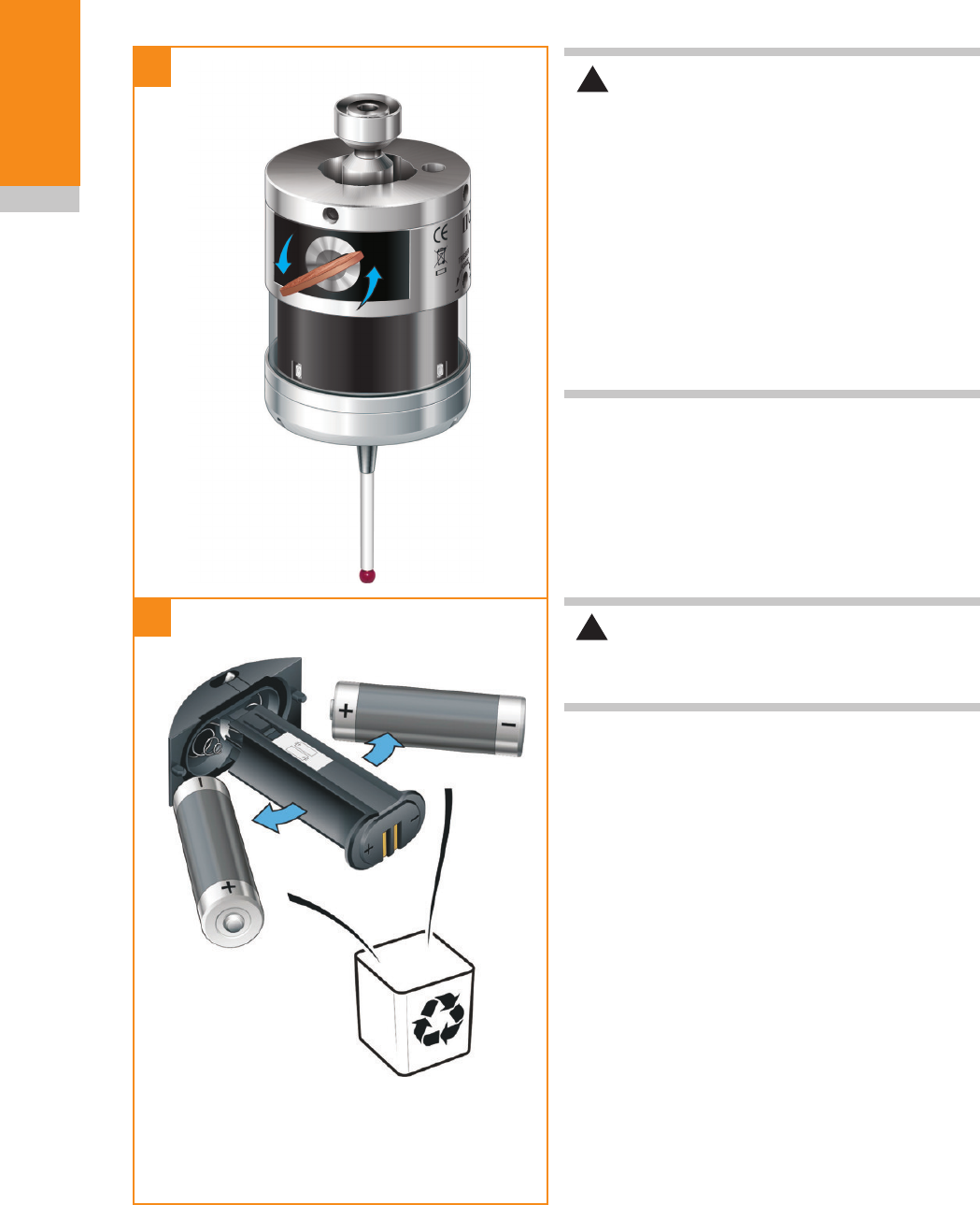
Batteries are inserted or removed as shown (see
‘Installing the batteries’ for further information).
On insertion of batteries, the LEDs will begin to
flash (see ‘Reviewing current probe settings’ for
further information).
Systeminterface
The RMI or RMI-Q are integrated interfaces/
receivers used to communicate between the
RMP60 probe and the machine control.
RMP60basics
Draft copy 09/07/12

RMP60 installation guide
2.2
RMP60 basics
Trigger Logic™
Trigger Logic™ (see Section 4 - Trigger Logic™)
is a method that allows the user to view and select
all available mode settings in order to customise
a probe to suit a specific application. Trigger
Logic™ is activated by battery insertion and uses
a sequence of stylus deflection (triggering) to
systematically lead the user through the available
choices to allow selection of the required mode
options.
Current probe settings can be reviewed by
simply removing the batteries for a minimum of
5 seconds, and then replacing them to activate
the Trigger Logic™ review sequence.
Modes of operation
The RMP60 probe can be in one of three modes:
Standby mode: where the probe is awaiting a
switch on signal.
Operational mode: activated by one of the switch
on methods described on this page. In this mode
the RMP60 is ready for use.
Configuration mode: where Trigger Logic™ may
be used to configure the following probe settings.
Hibernation mode: ??????
Configurable settings
Switch on/switch off methods
The following switch on/switch off options are
user-configurable.
1. Radio on/Radio off
2. Radio on/Timer off
3. Spin on/Spin off
4. Spin on/Timer off
5. Shank switch on/Shank switch off
Draft copy 09/07/12

2.3
RMP60 basics
RMP60 switch on method
Switch on options are configurable
RMP60 switch off method
Switch off options are configurable
Switch on time
Radio on
Radio switch on is commanded by
machine input.
Radio off
Radio switch off is commanded by
machine input. A timer automatically
switches the probe off 90 minutes
after the last trigger if it is not turned
off by machine input.
Timer off (timeout)
Timeout will occur 12, 33 or 134
seconds (user configurable) after the
last probe trigger or reseat.
1 second maximum
(see note below).
Spin on
Spin at 500 rev/min for 1 second
minimum.
Spin off
Spin at 500 rev/min for 1 second
minimum. A timer automatically
switches the probe off 90 minutes
after the last trigger if it is not spun.
Timer off (timeout)
Timeout will occur 12, 33 or 134
seconds (user configurable) after the
last probe trigger or reseat.
1 second maximum
(see note below).
Shank switch on Shank switch off 1 second maximum.
NOTES:
In ‘radio on’ mode, the switch on time is user
selectable 0.5 or 1.0 second maximum when
using RMI-Q (selection is made in RMI-Q).
Otherwise 1.0 second maximum.
In ‘radio on’ mode, the switch on time assumes
a good radio communication link. In a poor RF
environment this may rise to a maximum of 3.0
seconds.
For more information on the user selectable switch
on time when operating with RMI-Q, please refer
to the RMI-Q installation guide.
In 'spin on mode , the 2 seconds starts from the
moment the spindle reaches 500 rev/min.
After being switched on, the RMP60 must be on
for 1 second minimum before being switched off.
Draft copy 09/07/12

RMP60 installation guide
2.4
RMP60 basics
Enhanced trigger filter
Probes subjected to high levels of vibration or
shock loads may output probe trigger signals
without having contacted any surface. The
enhanced trigger filter improves the probe’s
resistance to these effects.
When the filter is enabled, a constant nominal 10
or 20 ms delay is introduced to the probe output.
It may be necessary to reduce the probe
approach speed to allow for the increased stylus
overtravel during the extended time delay.
Factory set to OFF.
Hibernation mode
Only applicable to ‘radio-on’ mode.
When RMP60 is in standby and RMI or RMI-Q
is powered off or out of range, the probe enters
hibernation; a low power mode designed to save
battery life. The probe ‘wakes’ from hibernation to
periodically check for it’s partnered RMI or RMI-Q.
The 'wake-up frequency can be set to 30 seconds,
5 seconds or set to off; the probe never goes into
hibernation.
Factory set to 30 seconds.
Multiple probe mode
The RMP60 can be configured, using Trigger
Logic™, to allow multiple radio probes in ‘spin on/
off’ or ‘shank on/off’ to be used with a single RMI
or RMI-Q.
Up to four RMP60s can be used with a single
RMI-Q in ‘radio on/off’ mode. For further details
of this functionality, please refer to the RMI-Q
installation guide.
NOTES:
Multiple probe mode is a function of the RMP60,
as such, the option will not appear when the 'radio
on' option has been selected.
RMP60 probes which are set to 'multiple probe
mode on' can coexist alongside any number of
RMP60 probes set to 'multiple probe mode off'.
To allow multiple radio probes to work in close
proximity, and with a single RMI or RMI-Q, 16
choices of 'mode on' colours are available, each
representing a different machine tool installation.
See 'Multiple probe settings' in Section 4 -
Trigger Logic™.
All probes operating with a single RMI or RMI-Q
must be set to the same 'mode on' colour choice;
any multiple probes located on adjacent machines
must all be set to an alternative 'mode on' colour
choice. Only one probe per 'mode on' colour
choice needs to be partnered with the RMI or
RMI-Q as, by configuring multiple probes to a
single 'mode on' colour choice, all probes using
this 'mode on' colour choice will have the same
identity. The probe to be partnered is partnered
after selecting the 'multiple probe mode' setting
and choosing the 'mode on' option. See 'Changing
the probe settings' in Section 4 - Trigger Logic™.
There is no limit to the number of probes that can
be used with a single RMI or RMI-Q so long as
they all have the same 'mode on' colour choice. All
RMP60 probes are factory set to 'mode off'.
The addition of any further probe(s) into a single
probe installation will require that all probes are
reconfigured to the same 'mode on' colour choice
and that one of the probes are then repartnered
with the RMI or RMI-Q.
The addition of any further probe(s), or
replacements, into a multi-probe installation can
be achieved simply through the reconfiguration of
the probe to the same 'mode on' colour choice.
Draft copy 09/07/12

2.5
RMP60 basics
Acquisition mode
System set-up is achieved using Trigger Logic™
and powering on the RMI or RMI-Q.
Partnering is only required during initial system
set-up. Further partnering is only required if either
the RMP60 or RMI/RMI-Q is changed.
NOTES:
Systems using the RMI-Q can be partnered with
up to four RMP60s manually. Alternatively this
can be achieved by using ReniKey; a Renishaw
machine macro cycle which does not require the
RMI-Q to be powered cycled.
Partnering by ReniKey is not available for RMI.
Partnering will not be lost by reconfiguration of
probe settings or when changing batteries, except
where multiple probe mode is selected .
Partnering can take place anywhere within the
operating envelope.
Draft copy 09/07/12
RMP60 installation guide
2.6
RMP60 basics
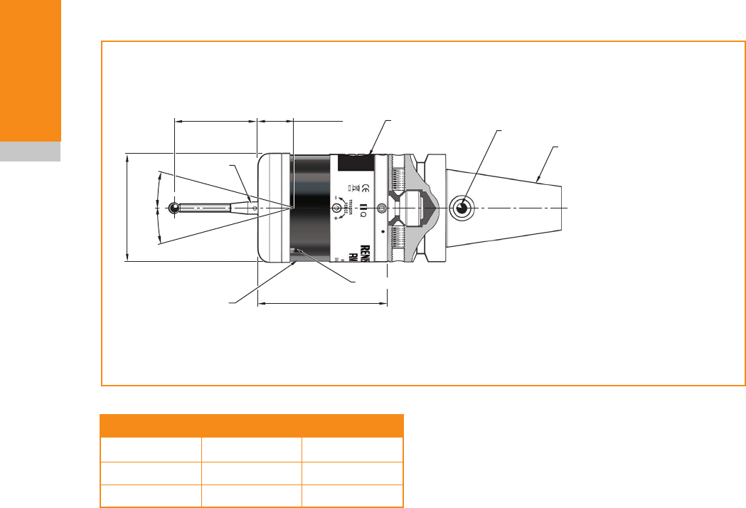
RMP60 dimensions
Stylus overtravel limits
Stylus length ±X/±Y Z
50 (1.97) 21 (0.82) 11 (0.43)
100 (3.94) 37 (1.45) 11 (0.43)
Dimensions given in mm (in)
A range of probe-ready
shanks are available from
Renishaw
50 (1.97) 19 (0.75) Battery cassette
Shank switch (optional)
Window
18°
18°
Ø63 (Ø2.48)
76 (2.99)
M4 stylus
Probe status LED
Draft copy 09/07/12

2.7
RMP60 basics
RMP60 specification
Principal application Workpiece measurement and job set-up on medium to large
horizontal, vertical and gantry machining centres, 5-axis machines,
twin spindle machines and vertical turret lathes.
Dimensions Length
Diameter
76 mm (2.99 in)
63 mm (2.48 in)
Weight (without shank) With batteries
Without batteries
876 g (30.90 oz)
826 g (29.14 oz)
Transmission type Frequency hopping spread spectrum (FHSS) radio
Radio frequency 2400 MHz to 2483.5 MHz
Switch-on methods Radio M code, spin on or shank switch
Switch-off methods Radio M code, timer, spin off or shank switch
Spindle speed (maximum) 1000 rev/min
Operating range Up to 15 m (49.2 ft)
Receiver/interface RMI or RMI-Q combined interface and receiver unit
Sense directions Omni-directional ±X, ±Y, +Z
Repeatability 1.00 µm (40 µin) 2 sigma – 50 mm stylus length (see note 1)
Stylus trigger force (see
notes 2 and 3)
Factory setting:
XY low force
XY high force
Z
0.75 N, 75 gf (2.64 ozf)
1.40 N, 140 gf (4.92 ozf)
5.30 N, 530 gf (18.69 ozf)
Maximum setting:
XY low force
XY high force
Z
2.0 N, 200 gf (7.0 ozf)
3.5 N, 350 gf (12.3 ozf)
14.0 N, 1400 gf (49.38 ozf)
Minimum setting:
XY low force
XY high force
Z
0.50 N, 50 gf (1.7 ozf)
0.90 N, 90 gf (3.2 ozf)
3.50 N, 350 gf (12.35 ozf)
Stylus overtravel XY plane
+Z plane
±18°
11 mm (0.43 in)
Note 1 Performance specification is achieved at a standard test velocity of 480 mm/min (18.9 in/min) with ceramic
styli. Significantly higher velocity is possible depending on application requirements.
Note 2 Trigger force, which is critical in some applications, is the force exerted on the component by the stylus
when the probe triggers.
The maximum force applied will occur after the trigger point i.e. overtravel. The force value depends on
related variables including measuring speed and machine deceleration.
Note 3 Tests carried out using a 50 mm stylus.
Draft copy 09/07/12

NOTE: 5% usage = 72 minutes/day.
RMP60 installation guide
2.8
RMP60 basics
Battery type Shank switch on Spin switch on
Standby life 5% usage Continuous
Use
Standby life 5% usage Continuous
Use
Alkaline TBA days TBA days TBA hours TBA days TBA days TBA hours
Lithium Thionyl
Chloride TBA days TBA days TBA hours TBA days TBA days TBA hours
Environment IP rating IPX8
Storage temperature -25 °C to +70 °C (-13 °F to +158 °F)
Operating temperature +5 °C to +55 °C (+41 °F to +131 °F)
Battery types 2 x AA 1.5 V alkaline or 2 x AA 3.6 V Lithium Thionyl Chloride
Battery reserve life Approximately one week after a low battery warning is first given.
Typical battery life See table below.
Rechargeable
batteries
Either Nickel Cadmium (NiCd) or Nickel Metal Hydride (NiMh) can be
used. However, when these battery types are fitted, expect a battery life of
approximately 50% less than that quoted for alkaline batteries together with
a reduced low battery warning period.
Battery type Radio switch on
(1 second turn on)
Radio switch on
(0.5 second turn on)
Continuous use
Standby life 5% usage Standby life 5% usage
Alkaline TBA days TBA days TBA days TBA days TBA hours
Lithium Thionyl
Chloride TBA days TBA days TBA days TBA days TBA hours
Draft copy 09/07/12
3.1
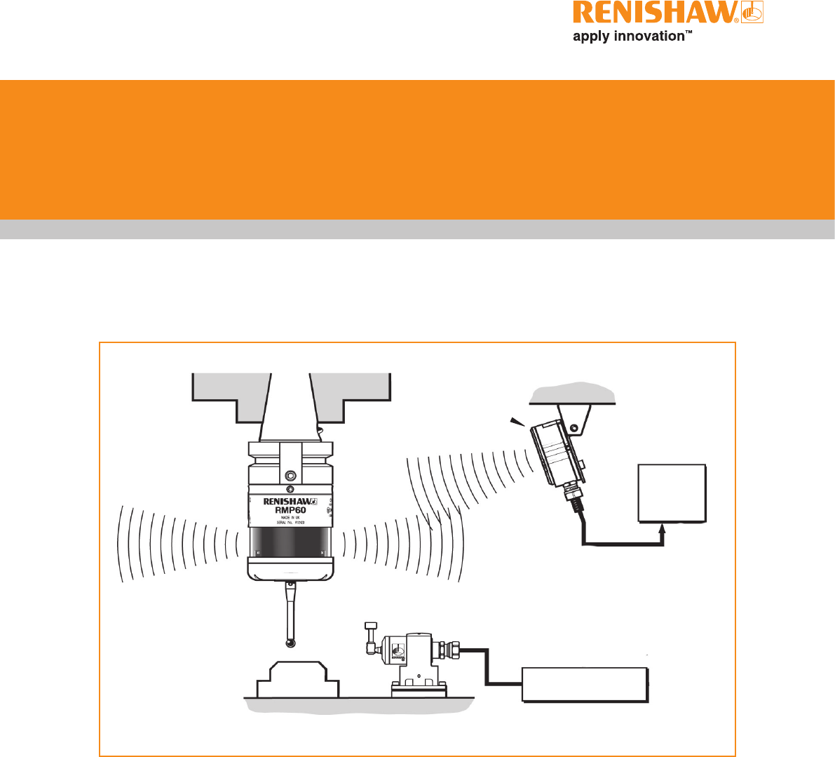
Installing the RMP60 with an RMI
or RMI-Q
CNC machining
centre spindle
RMP60 inspection
probe
RMI or RMI-Q
interface Mounting
bracket
CNC
machine
control
Interface unit
Typical tool
setting probe
Workpiece
Stylus
System installation
Operating envelope
Radio transmission does not require line-of-
sight and will pass through very small gaps
and machine tool windows. This allows easy
installation, either inside or outside the machine
enclosure.
Coolant and swarf residue accumulating on
the RMP60 and RMI or RMI-Q may have a
detrimental effect on transmission performance.
Wipe clean as often as is necessary to maintain
unrestricted transmission.
When operating, do not touch either the RMI or
RMI-Q cover or the probe glass window with your
hand, as this will affect the performance.
Draft copy 09/07/12
Valid between temperatures of
+5 °C to +55 °C (+41 °F to +131 °F)
RMP60 installation guide
3.2
System
installation
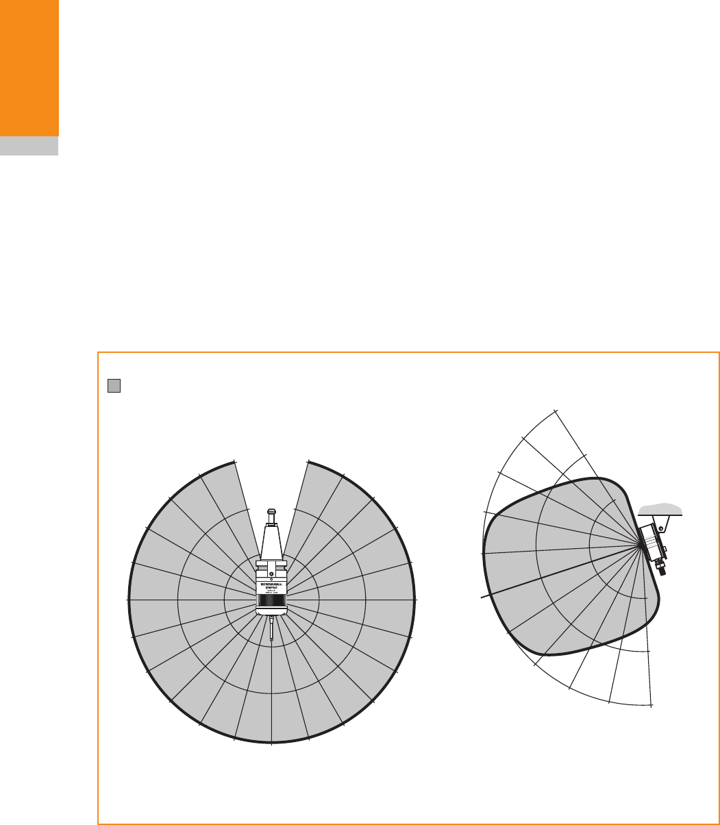
Performance envelope when using the
RMP60 with the RMI or RMI-Q
RMP60 / RMI or RMI-Q positioning
The probe system should be positioned so that
the optimum range can be achieved over the full
travel of the machine's axes. Always face the front
cover of the RMI or RMI-Q in the general direction
of the machining area and the tool magazine,
ensuring both are within the performance
envelope shown below. To assist in finding the
optimum position of the RMI or RMI-Q, the signal
quality is displayed on an RMI or RMI-Q signal
LED.
Range metres (feet)
OPERATING AND SWITCH ON/OFF
75°
60°
45°
30°
15°
0°
15°
30°
45°
60°
75° 90° 75°
60°
45°
30°
15°
0°
15°
45°
60°
75°
75°
60°
45°
30°
30°
45°
60° 75°
10 (33)
15 (49)
5 (16)
5 (16)
10 (33)
15 (49)
15°
0°
15°
30°
5
(16)
10
(33)
15
(49)
RMP60 probe
RMI or
RMI-Q
Performance envelope
The RMP60 and RMI or RMI-Q must be within
each other's performance envelope as shown
below. The performance envelope shows line-of-
sight performance, however radio transmission
does not require this as any reflected radio paths
will be less than the 15 m (49.2 ft) operating
range.
Draft copy 09/07/12
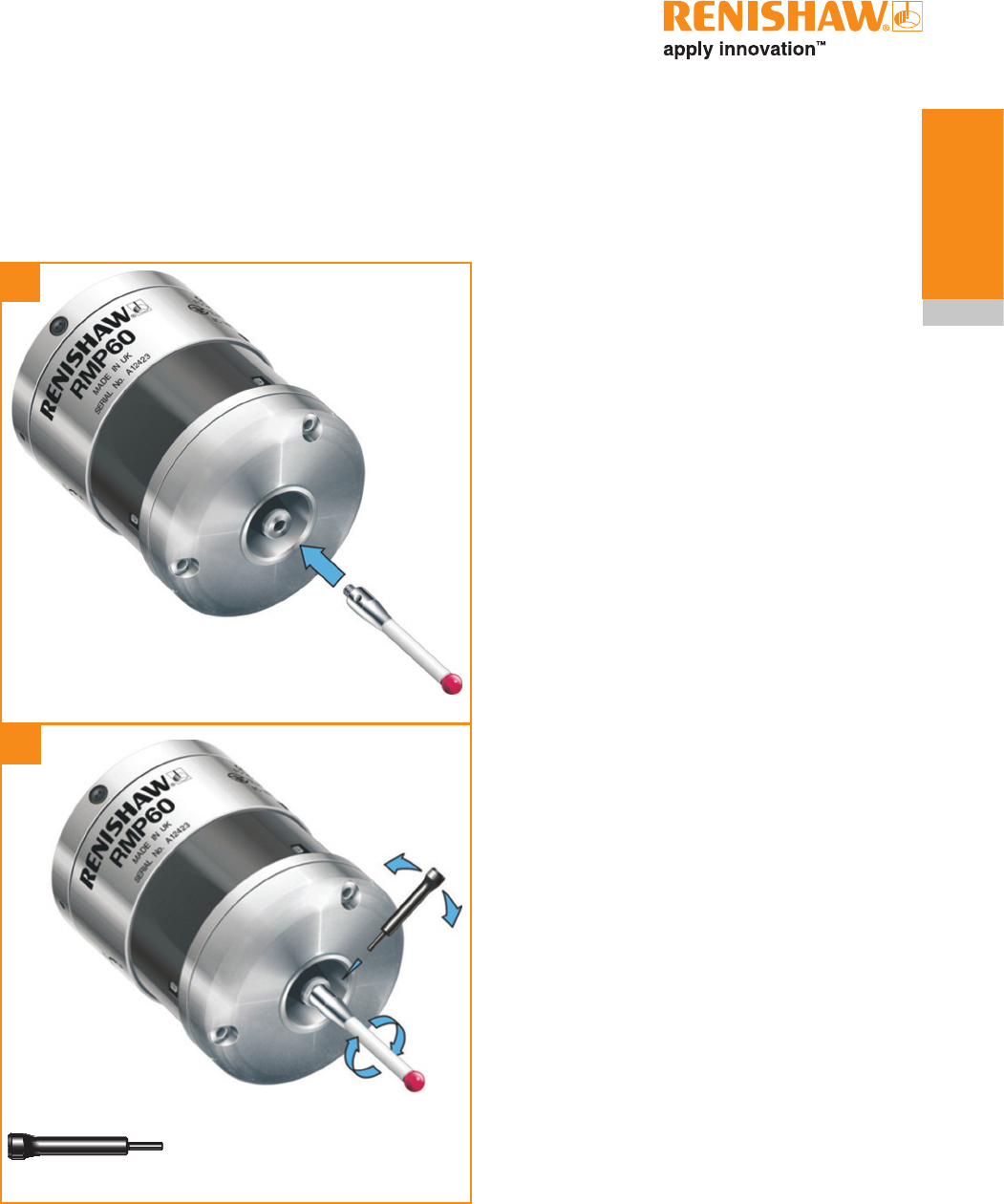
1
2
3.3
System
installation
Preparing the RMP60 for use
Fitting the stylus
M-5000-3707
1,8 Nm – 2,2 Nm
(1.3 lbf.ft – 1.6 lbf.ft)
Draft copy 09/07/12
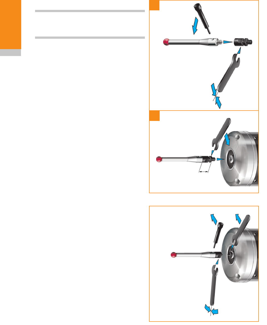
1
2
RMP60 installation guide
3.4
System
installation
Stylus weak link
NOTE: Must be used with steel styli. For optimum
metrology performance do not use a weak link
with ceramic or carbon fibre styli.
Fitting stylus with weak link onto RMP60
In the event of excessive stylus overtravel, the
weak link is designed to break, thereby protecting
the probe from damage.
Take care to avoid stressing the weak link during
assembly.
Removing a broken weak link
2 Nm (1.5 lbf.ft)
5 mm AF
2 Nm (1.5 lbf.ft)
12 mm
(0.47 in)
The stylus colouring in these
three illustrations has been
changed to reflect a steel styli
more, as the note says "do not
use a weak link with ceramic
or carbon fibre styli" and we
showed it with a ceramic styli
Draft copy 09/07/12
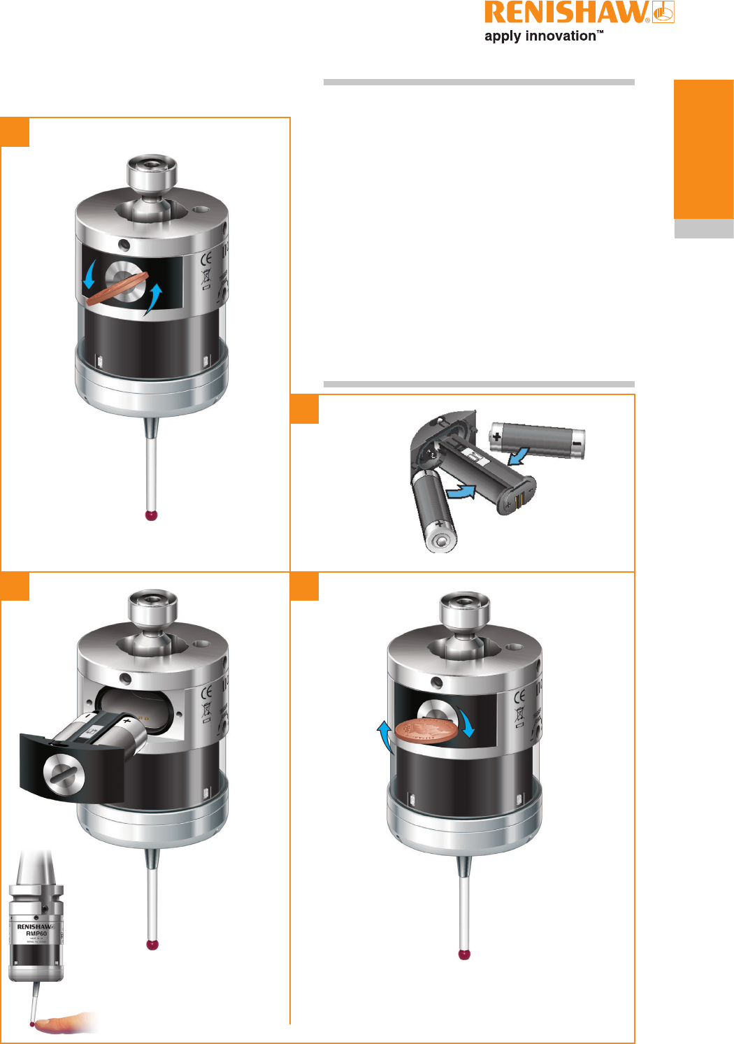
1
2
34
X
3.5
System
installation
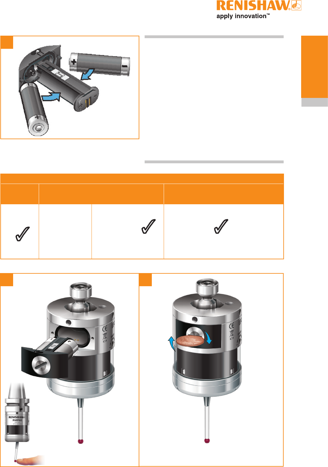
Installing the batteries NOTES:
See Section 5 - Maintenance for a list of suitable
battery types.
Ensure the product is clean and dry before
inserting batteries.
Do not allow coolant or debris to enter the battery
compartment.
When inserting batteries, check that the battery
polarity is correct.
After inserting the batteries the LEDs will display
the current probe settings (for details, see
Section 4 - Trigger Logic™).
Draft copy 09/07/12
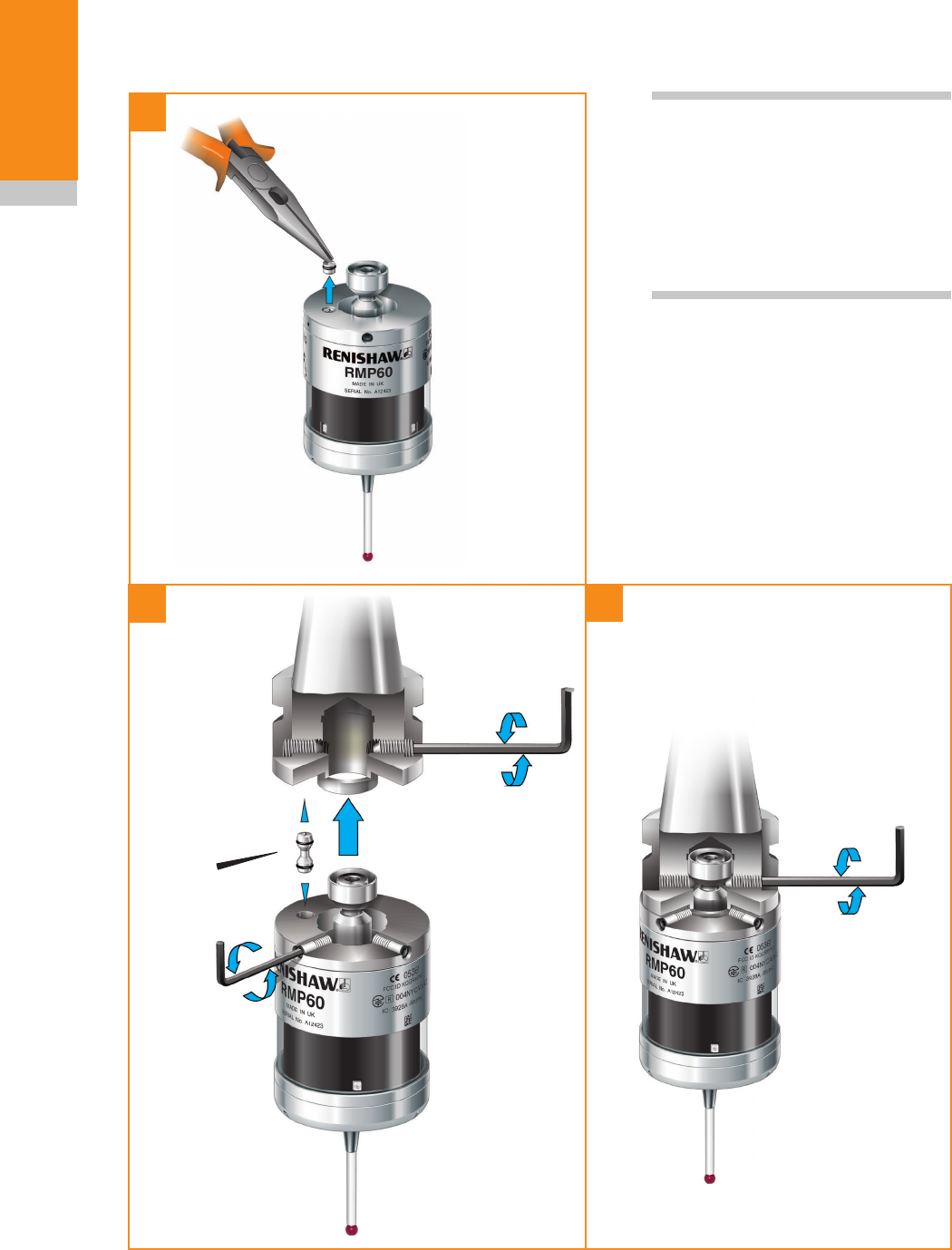
1
3
2
RMP60 installation guide
3.6
System
installation
Mounting the probe on a shank (or
machine table)
2 Nm – 3 Nm
(1.5 lbf.ft – 2.2 lbf.ft)
NOTE: In instances where the
RMP60 is to be used with a shank
switch, it will be necessary to
remove the plug from the rear of
the probe using pliers. This should
then be substituted with the bobbin
(A‑4038‑0303).
Bobbin
(A‑4038‑0303)
(x 2)
(x 2)
(x 4)
Draft copy 09/07/12
1
23
3.7
System
installation
1 Nm
(0.74 lbf.ft)
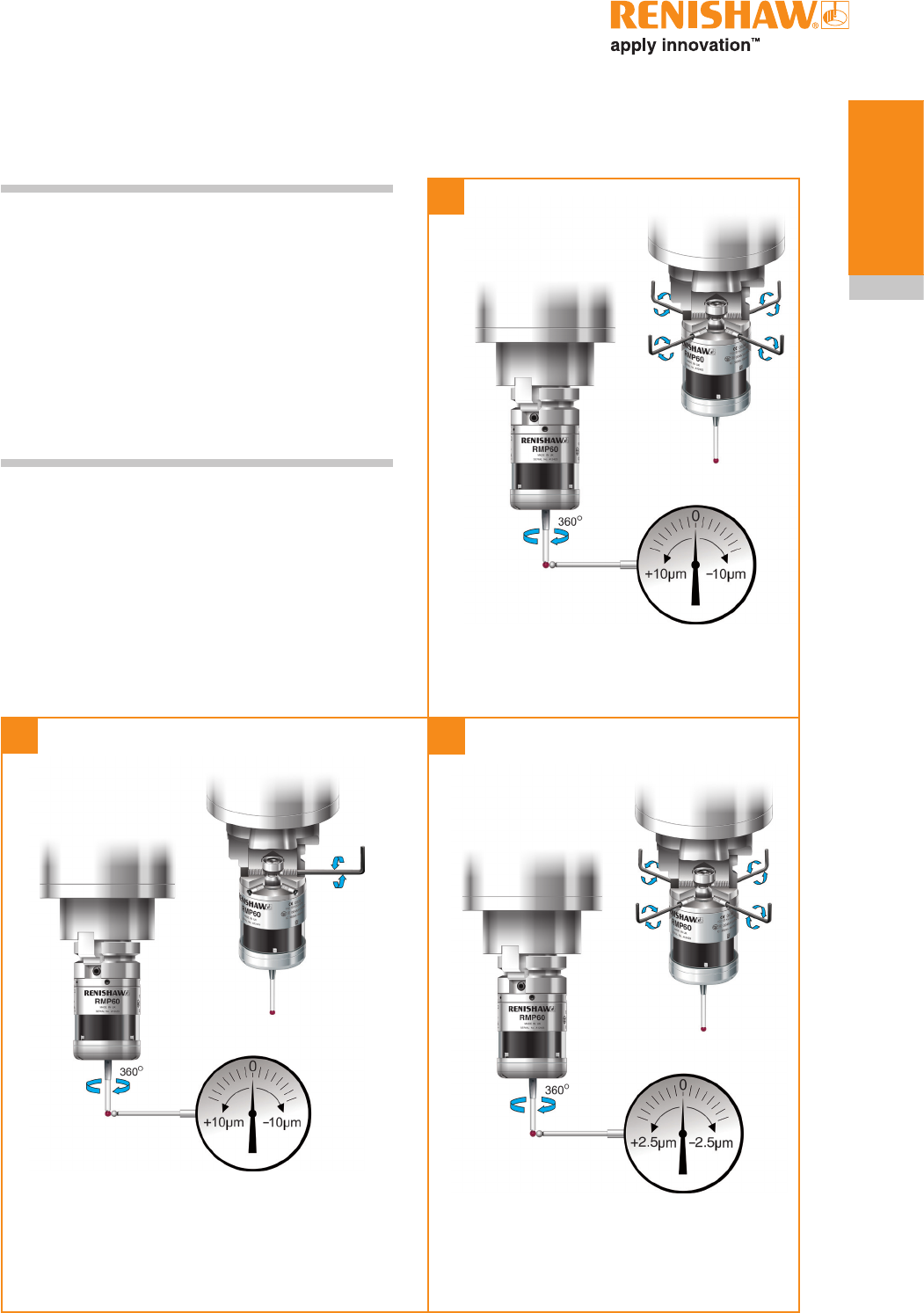
Stylus on-centre adjustment
6 Nm – 8 Nm
(4.4 lbf.ft
– 5.9 lbf.ft)
1.5 Nm – 3.2 Nm
(1.1 lbf.ft – 2.4 lbf.ft)
NOTES:
During adjustment, care must be taken not to
rotate the probe relative to the shank, as damage
to the bobbin (A-4038-0303) can occur where
fitted.
If a probe and shank assembly is dropped, it must
be rechecked for correct on-centre adjustment.
Do not hit or tap the probe to achieve on-centre
adjustment.
(x 4)
(x 2)
(x 4)
Draft copy 09/07/12

RMP60 installation guide
3.8
System
installation
Stylus trigger force and
adjustment
Spring force within the probe causes the stylus to
sit in a unique position and return to this position
following each stylus deflection.
Stylus trigger force is set by Renishaw. The
user should only adjust trigger force in special
circumstances e.g. where there is excessive
machine vibration or insufficient force to support
the stylus weight.
To adjust the trigger force, turn the adjusting
screw anticlockwise to reduce the force (more
sensitive) or clockwise to increase the force (less
sensitive). A stop helps to prevent damage which
could be caused by overtightening the adjusting
screw.
XY trigger forces vary around the stylus seating.
Factory setting
XY low force 0.7 N, 75 gf (2.64 ozf)
XY high force 1.4 N, 140 gf (4.92 ozf)
Z 5.30 N, 530 gf (18.69 ozf)
Maximum setting
XY low force 2 N, 200 gf (7.0 ozf)
XY high force 3.5 N, 350 gf (12.3 ozf)
Z 14 N, 1400 gf (49.38 ozf)
Minimum setting
XY low force 0.5 N, 50 gf (1.7 ozf)
XY high force 0.9 N, 90 gf (3.2 ozf)
Z 3.5 N, 350 gf (12.35 ozf)
Reduce
force
Increase
force
2 mm AF
Draft copy 09/07/12

3.9
System
installation
Calibrating the RMP60
Why calibrate a probe?
A spindle probe is just one component of the
measurement system which communicates with
the machine tool. Each part of the system can
introduce a constant difference between the
position that the stylus touches and the position
that is reported to the machine. If the probe is
not calibrated, this difference will appear as an
inaccuracy in the measurement. Calibration of the
probe allows the probing software to compensate
for this difference.
During normal use, the difference between the
touch position and the reported position does
not change, but it is important that the probe is
calibrated in the following circumstances:
• when a probe system is to be used for the
first time;
• when the enhanced trigger filter delay is
changed;
• when a new stylus is fitted to the probe;
• when it is suspected that the stylus has
become distorted or that the probe has
crashed;
• at regular intervals to compensate for
mechanical changes of your machine tool;
• if repeatability of relocation of the probe
shank is poor. In this case, the probe may
need to be recalibrated each time it is
selected.
It is good practice to set the tip of the stylus
on-centre, because this reduces the effect of
any variation in spindle and tool orientation (see
'Stylus on-centre adjustment' in Section 3 -
System Installation). A small amount of run-out
is acceptable, and can be compensated for as
part of the normal calibration process.
Three different operations are to be used when
calibrating a probe. They are:
• calibrating either in a bored hole or on a
turned diameter of known position;
• calibrating either in a ring gauge or on a
datum sphere;
• calibrating the probe length.
Calibrating in a bored hole or on a
turned diameter
Calibrating a probe, either in a bored hole or on
a turned diameter of known size, automatically
stores values for the offset of the stylus ball to
the spindle centre-line. The stored values are
then used automatically in the measuring cycles.
Measured values are compensated by these
values so that they are relative to the true spindle
centre-line.
Calibrating in a ring gauge or on a
datum sphere
Calibrating a probe either in a ring gauge or
on a datum sphere with a known diameter
automatically stores one or more value for the
radius of the stylus ball. The stored values are
then used automatically by the measuring cycles
to give the true size of the feature. The values are
also used to give true positions of single surface
features.
NOTE: The stored radius values are based on
the true electronic trigger points. These values are
different from the physical sizes.
Calibrating the probe length
Calibrating a probe on a known reference surface
determines the length of the probe, based on
the electronic trigger point. The stored value for
length is different from the physical length of the
probe assembly. Additionally, the operation can
automatically compensate for machine and fixture
height errors by adjusting the probe length value
that is stored.
Draft copy 09/07/12

RMP60 installation guide
3.10
System
installation
This page left intentionally blank
Draft copy 09/07/12
X
4.1
> 5 s
12
3
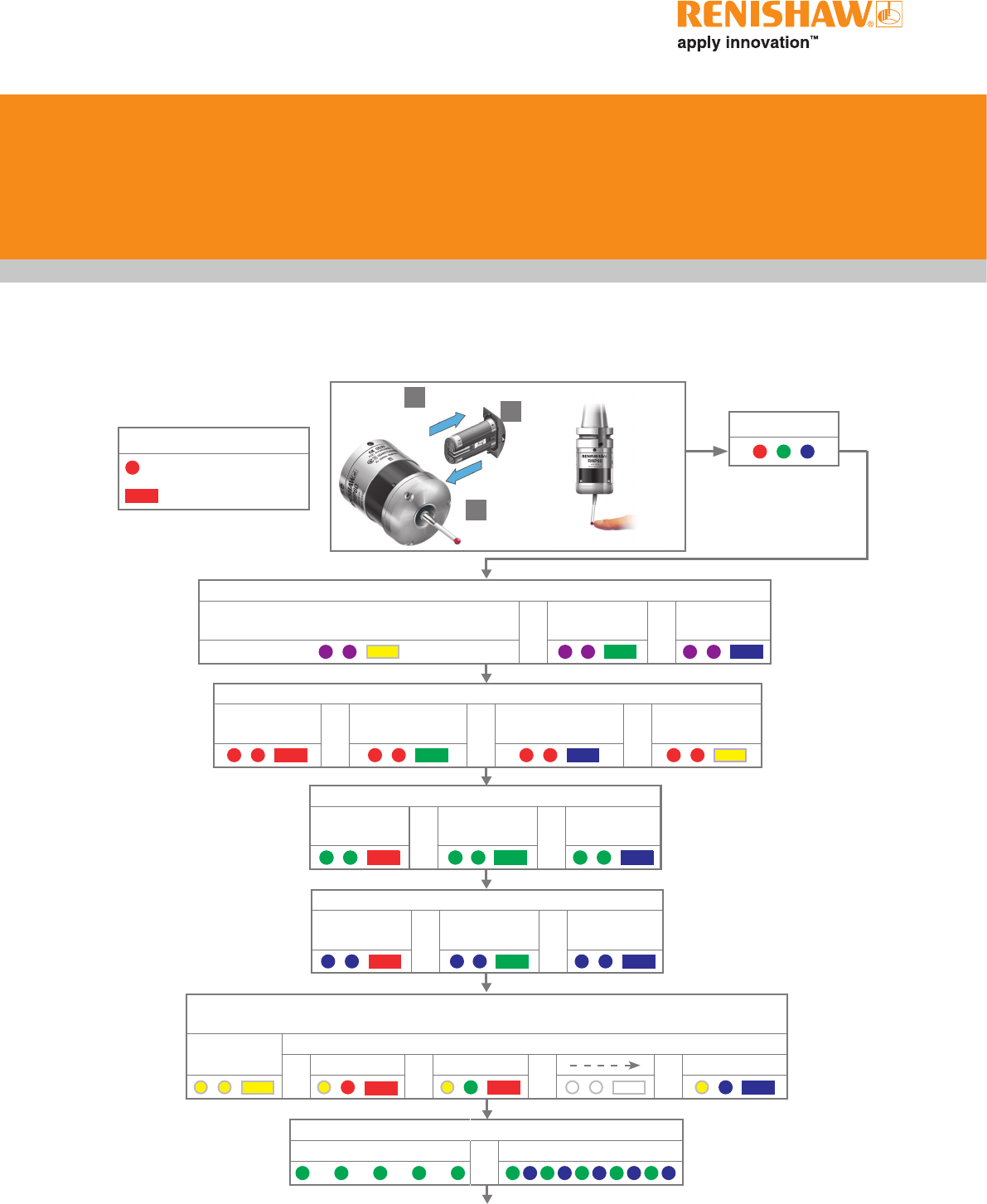
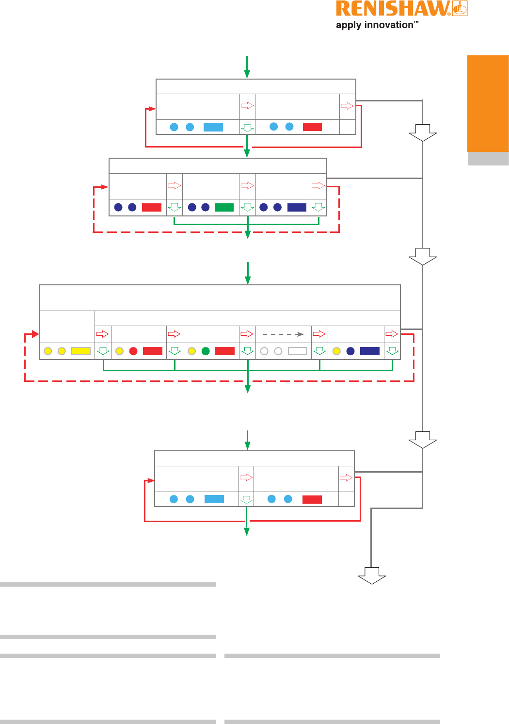
Key to the symbols
LED short flash
LED long flash
Switch on method
Radio on
(omitted if multiple probe mode is selected) or
Shank on
or
Spin on
Switch off method (omitted for shank on)
Radio off or
Spin off or
Short timeout
12 s or
Medium timeout
33 s or
Long timeout
134 s
LED check
Probe in standby mode
Battery status
Battery good or Battery low
Multiple probe mode (omitted for radio on)
see "Multiple probe mode settings" to view all 16 choices
Mode off Mode on
or Machine 1 or Machine 2 or or Machine 16
Reviewing the current probe
settings
Trigger Logic™
Enhanced trigger filter setting
Off
0 ms or
On
10 ms or
On
20 ms
Enhanced trigger filter setting
Off
0 ms or
On
10 ms or
On
20 ms
Hibernation mode setting (only for radio on)
On
30 s or
On
5 s or
Off
Draft copy 09/07/12
RMP60 installation guide
4.2
Trigger Logic™
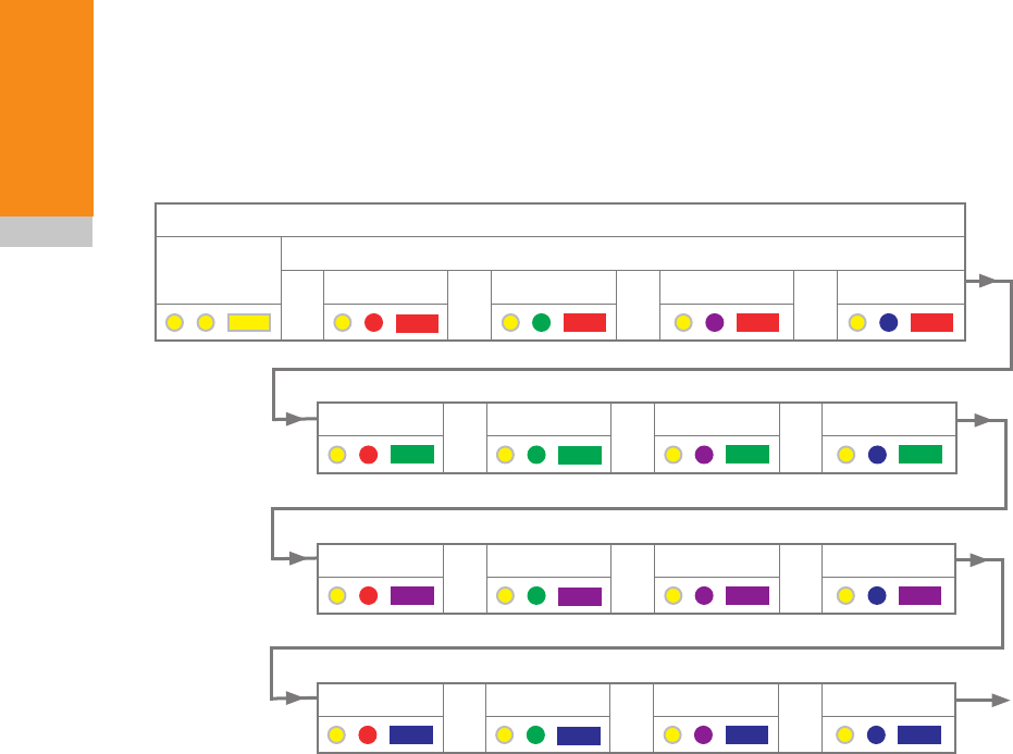
Multiple probe settings
Deflect the stylus for less than 4 seconds to
cycle to the next setting.
Multiple probe mode
Mode off Mode on
or Machine 1 or Machine 2 or Machine 3 or Machine 4
Machine 5 or Machine 6 or Machine 7 or Machine 8
Machine 9 or Machine 10 or Machine 11 or Machine 12
Machine 13 or Machine 14 or Machine 15 or Machine 16
Return to
"Mode off"
Draft copy 09/07/12

4.3
Trigger Logic™
Factory
settings
New
settings
Switch on method Radio on ✔
Shank on
Spin on
Switch off method Radio or spin ✔
Short timeout (12 s)
Medium timeout (33 s)
Long timeout (134 s)
Enhanced trigger filter
setting
Off (0 ms) ✔
On (10 ms)
On (20 ms)
Hibernation mode
setting
On (30 s) ✔
On (5 s)
Off
Multiple probe mode Off (factory set) ✔
On (machine number) See "Multiple
probe settings"
RMP60 serial no ........................................
✔ tick
Probe settings record
This page is provided to note your probe's
settings.
✔ tick
Factory settings are for kit (A-5742-0001) only.
Draft copy 09/07/12
X
RMP60 installation guide
4.4
Trigger Logic™
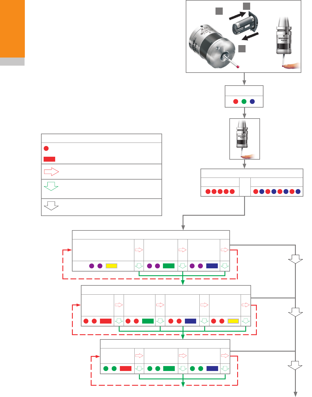
Switch on method
Radio on
(omitted if multiple
probe mode is selected)
Shank on Spin on
> 5 s
12
3
Key to the symbols
LED short flash
LED long flash
Deflect the stylus for less than 4 seconds
to move to the next menu option.
Deflect the stylus for more than
4 seconds to move to the next menu.
To exit, leave the stylus untouched for
more than 20 seconds.
LED check
Battery status
Battery good or Battery low
Changing the probe settings
Insert the batteries or, if they have already been
installed, remove them for five seconds and then
refit them.
Following the LED check, immediately deflect the
stylus and hold it deflected until five red flashes
have been observed (if the battery power is low
then each of the five red flashes will be followed
by a blue flash).
Keep the stylus deflected until the "Switch on
method" setting is displayed, then release the
stylus. The probe is now in configuration mode
and Trigger Logic™ is activated.
Switch off method (omitted for shank on)
Radio off or
Spin off
Short
timeout
12 s
Medium
timeout
33 s
Long
timeout
134 s
continued on next
page
Enhanced trigger filter setting
Off
0 ms
On
10 ms
On
20 ms
3
Draft copy 09/07/12
4.5
Trigger Logic™
NOTE: If using mutiple probe mode refer to
the RMI installation guide (H-4113-8554) or the
RMI-Q installation guide (H-5687-8504).
Cease triggering here, unless the multiple probe mode is required
in which case deflect stylus > 4 seconds
Acquisition mode
off
Acquisition mode
Return to “Change switch-on method”
Acquisition mode
on
Acquisition mode
off
Acquisition mode
Acquisition mode
on
New settings
complete
Hibernation mode setting (only for radio on)
On
30 s
On
5 ms
Off
Multiple probe mode
(see "Multiple probe mode settings" to view all 16 choices)
Mode off Mode on
Machine 1 Machine 2 Machine 16
If no changes are made in multiple probe mode, then deflecting the stylus for more than
4 seconds will return the probe settings to "Switch-on method". If a multiple probe mode is
selected, proceed to "Acquisition mode" to repartner one probe with the RMI or RMI-Q.
NOTE: To partner an RMP60 with an RMI please
see "RMP60 – RMI partnership". Once acquisition
has been successful, the RMP60 will revert to
"Acquisition mode off".
NOTE: To partner an RMP60 with an RMI-Q
please see "RMP60 – RMI-Q partnership". Once
acquisition has been successful, the RMP60 will
revert to "Acquisition mode off".
Draft copy 09/07/12
RMP60 installation guide
4.6
Trigger Logic™
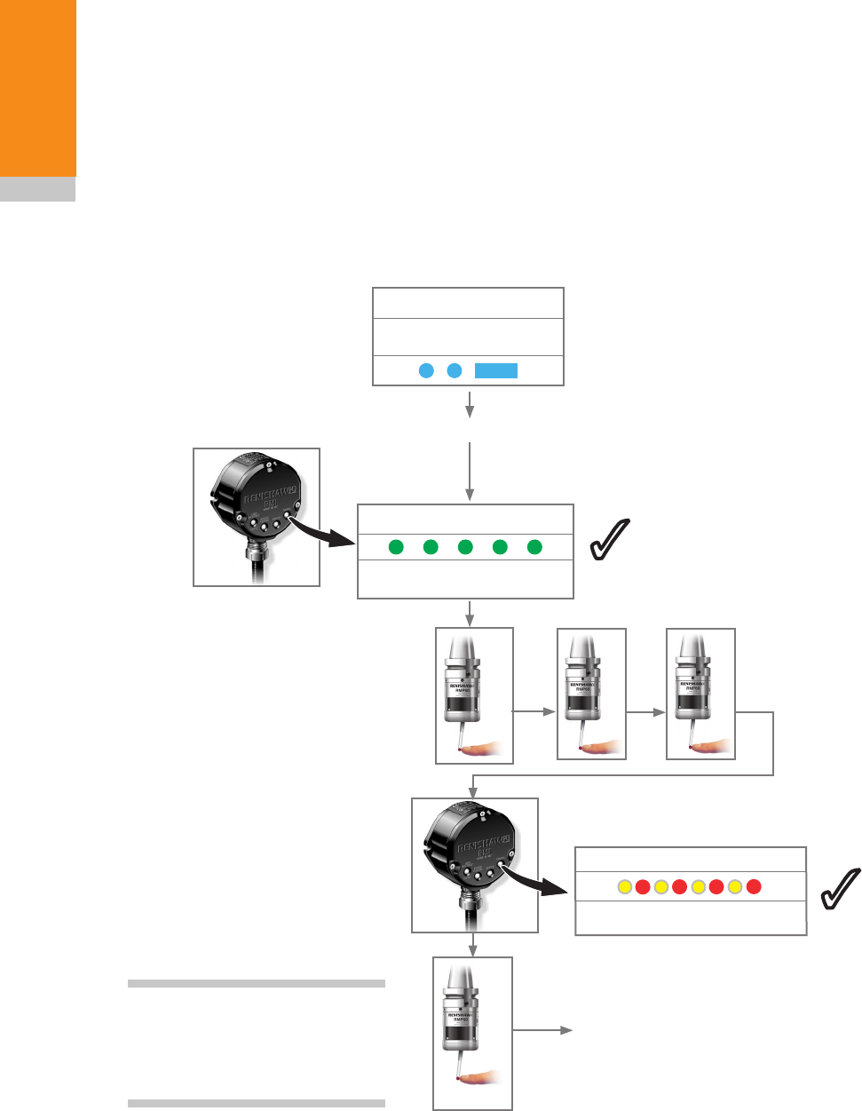
RMP60 – RMI partnership
System set-up is achieved using Trigger Logic™
and powering the RMI. Partnering is only required
during initial system set-up. Further partnering
is only required if either the RMP60 or RMI is
changed, or a system is reconfigured for multiple
probes (multiple probe mode).
Partnering will not be lost by reconfiguring the
probe settings or when changing batteries, except
where multiple probe mode is selected. Partnering
can take place anywhere within the operating
envelope.
In configuration mode, configure the probe
settings as required until you reach the
"Acquisition mode" menu, which defaults to
"Acquisition mode off".
3
The probe is in stand-by
and the system is ready
for use.
X
New partner RMP acquired
SIGNAL LED
> 20 s
X
3
Release and deflect
the stylus to select
"Acquisition mode on".
Ensure this is
done within 8
seconds of the
RMI signal LED
flashing green.
X
Switch on the RMI
Acquisition mode
Acquisition mode
off
SIGNAL LED
RMI
in acquisition mode
NOTE: Please also refer to
the RMI installation guide
(H-4113-8554) when partnering
the RMP60.
3
Draft copy 09/07/12
4.7
Trigger Logic™
RMP60 – RMI-Q partnership
System set-up is achieved using Trigger Logic™
and powering on the RMI-Q or applying ReniKey.
Partnering is required during initial system set-up.
Further partnering will be required if either the
RMP60 or RMI-Q is changed.
Any RMP60 that is partnered with RMI-Q, but
then used with another system, will need to be
partnered again when it is brought to the RMI-Q.
Partnering will not be lost by reconfiguring the
probe settings or when changing batteries.
Partnering can take place anywhere within the
operating envelope.
In configuration mode, configure the probe
settings as required until you reach the
"Acquisition mode" menu, which defaults to
"Acquisition mode off".
The probe is in stand-by
and the system is ready
for use.
X
> 20 s
X
3
X
Release and deflect
the stylus to select
"Acquisition mode on".
Ensure this is
done within 60
seconds of the
RMI-Q signal
LED flashing
green.
Switch on the RMI-Q
or
Acquisition mode
Acquisition mode
off
SYSTEM STATUS LED
RMI-Q in acquisition mode with
empty probe location
SYSTEM STATUS LED
RMI-Q in acquisition mode with
full probe location
3 3
NOTE: Please also refer to
the RMI-Q installation guide
(H-5687-8504) when partnering up
to four RMP60/RMP.
or
Displayed for 5 seconds
.
SYSTEM STATUS LED
Acquisition pending
SYSTEM STATUS LED
New partner RTS acquired
SYSTEM STATUS LED
RMP cleared from location
Draft copy 09/07/12
RMP60 installation guide
4.8
Trigger Logic™
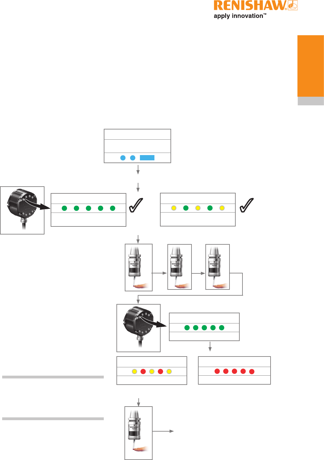
Operating mode
NOTE: Due to the nature of Lithium Thionyl
Chloride batteries, if a 'low battery' LED sequence
is ignored or overlooked, then it is possible for the
following sequence of events to occur:
1. When the probe is active, the batteries
discharge until battery power becomes too low
for the probe to operate correctly.
2. The probe stops functioning, but then
reactivates as the batteries recover sufficiently
to provide the probe with power.
3. The probe begins to run through the LED
review sequence (see 'Reviewing the
current probe settings' in Section 4 - Trigger
Logic™).
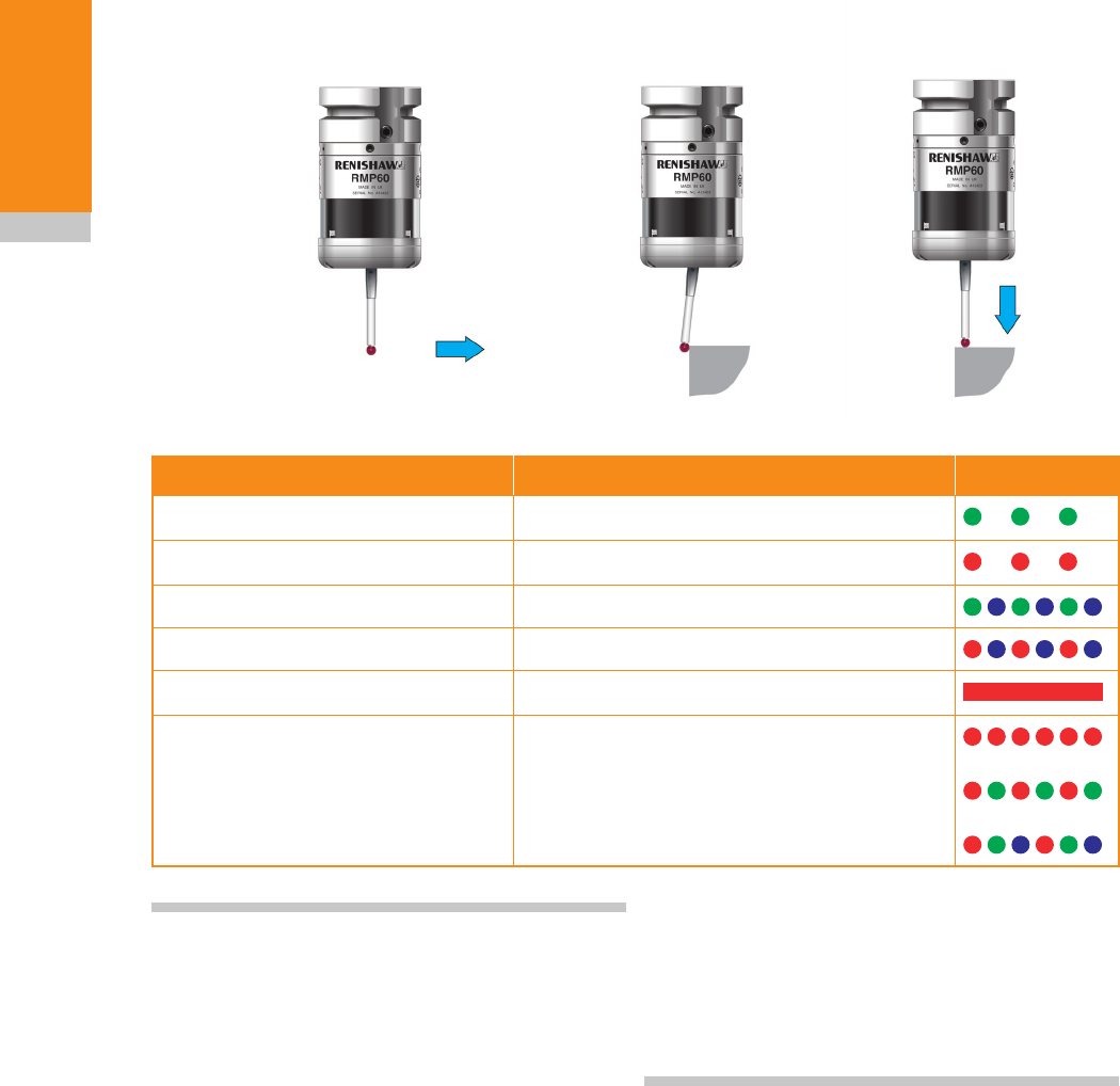
LED colour Probe status Graphic hint
Flashing green Probe seated in operating mode
Flashing red Probe triggered in operating mode
Flashing green and blue Probe seated in operating mode – low battery
Flashing red and blue Probe triggered in operating mode – low battery
Constant red Battery e
xhausted
Fast flashing red
or
Flashing red and green
or
Sequence when batteries are inserted
Exhausted battery or unsuitable battery
LEDs
flashing
green
LEDs
flashing
red
LEDs
flashing
red
X/Y Z
Probe status LEDs
4. Again, the batteries discharge and the probe
ceases to function.
5. Again, the batteries recover sufficiently
to provide the probe with power, and the
sequence is repeated.
Draft copy 09/07/12

5.1
Maintenance
You may undertake the maintenance routines
described in these instructions.
Further dismantling and repair of Renishaw
equipment is a highly specialised operation,
which must be carried out at authorised Renishaw
Service Centres.
Equipment requiring repair, overhaul or attention
under warranty should be returned to your
supplier.
Cleaning the probe
Wipe the window of the probe with a clean cloth
to remove machining residue. This should be
done on a regular basis to maintain optimum
transmission.
Maintenance
Draft copy 09/07/12
1
2
RMP60 installation guide
5.2
Maintenance
CAUTIONS:
Do not leave exhausted batteries in the probe.
When changing batteries, do not allow coolant or
debris to enter the battery compartment.
When changing batteries, check that the battery
polarity is correct.
Take care to avoid damaging the battery cassette
gasket.
Only use specified batteries.
Changing the batteries
CAUTION: Please dispose of exhausted
batteries in accordance with local regulations.
Never dispose of batteries in a fire.
!
!
Draft copy 09/07/12
3
45
X
5.3
Maintenance
NOTES:
After removing the old batteries, wait more than 5
seconds before inserting the new batteries.
Do not mix new and used batteries or battery
types, as this will result in reduced life and
damage to the batteries.
Always ensure that the cassette gasket and
mating surfaces are clean and free from dirt
before reassembly.
If dead batteries are inadvertently inserted into
the probe, the LEDs will remain a constant red.
Battery types
Alkaline
x 2
Lithium Thionyl Chloride
x 2
Nickel Cadmium/Nickel Metal Hydride
x2
AA 1.5 V RS:
Radio shack:
Saft:
Sonnenschein:
Tadrian:
Xeno:
596-602, 201-9438
23-037
LS 14500
SL-760/S
TL-5903/S, TL-2100/S
XL-060F
AA 1.2 V
33 3
Draft copy 09/07/12
RMP60 installation guide
5.4
Maintenance
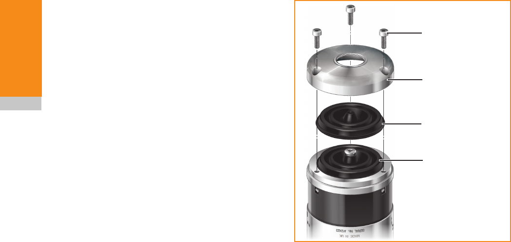
Diaphragm replacement
RMP60 diaphragms
The probe mechanism is protected from coolant
and debris by two diaphragms. These provide
adequate protection under normal working
conditions.
You should periodically check the outer diaphragm
for signs of damage. If this is evident, replace the
outer diaphragm.
Do not remove the inner diaphragm. If it is
damaged, return the probe to your supplier for
repair.
Outer diaphragm inspection
1. Remove the stylus.
2. Undo the three M3 front cover screws and
remove the front cover.
3. Inspect the outer diaphragm for damage.
4. To remove the outer diaphragm, grip by the
outer edge and pull off.
Inner diaphragm inspection
Inspect the inner diaphragm for damage. If it is
damaged, return the probe to your supplier. DO
NOT REMOVE THE INNER DIAPHRAGM AS
YOUR WARRANTY WILL BE INVALIDATED.
Outer diaphragm replacement
1 Fit the new diaphragm over the centre.
2. Locate the outer edge of the diaphragm
to rest on the outer edge of the inner
diaphragm.
3. Refit the front cover and M3 screws.
4. Refit the stylus and recalibrate the probe.
M3 screw
2.5 mm AF
1 Nm (0.74 lbf.ft)
Cover
Outer
diaphragm
Inner
diaphragm
Draft copy 09/07/12
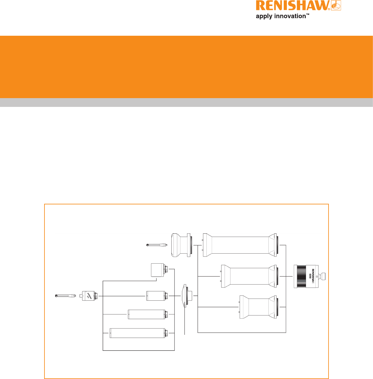
RMP60M
module
RMP60M extension L200
RMP60M /LP2 adaptor
M4 stylus
RMP60M probe
module
M4 stylus
LP2 probe
MA4 90° adaptor
LPE3 extension bar (150 mm)
LPE2 extension bar (100 mm)
LPE1 extension bar (50 mm)
RMP60M extension L150
RMP60M extension L100
6.1
RMP60M system
RMP60M is a special modular version of RMP60.
It enables probe inspection of part features
inaccessible to RMP60, by fitting selected
adaptors and extensions as shown below.
See Chapter 8, "Parts list".
RMP60M system
The above drawing has changed
to show the same orientation as
other probe views (i.e. right to
left).
Draft copy 09/07/12
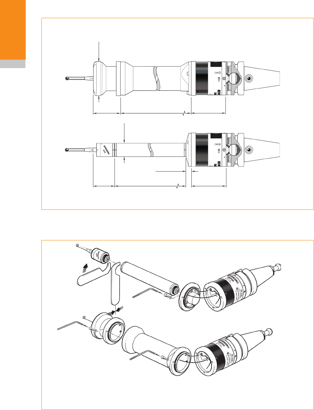
100/150/200
(3.94/5.91/7.87) 66.25 (2.61)
66.25 (2.61)
50/100/150
(1.97/3.94/5.91)
12.50 (0.49)
40.75
(1.60)
Ø25
(Ø0.98)
50.50
(1.99)
Ø63
(Ø2.48)
RMP60 installation guide
6.2
RMP60M system
RMP60M screw torque values
dimensions mm (in)
10 Nm to 12 Nm
(7.37 lbf.ft to 8.85 lbf.ft)
2.6 Nm
(1.92 lbf.ft)
2.6 Nm
(1.92 lbf.ft)
2.6 Nm
(1.92 lbf.ft)
RMP60M dimensions
Draft copy 09/07/12