Ricoh Priport Vt2130 Users Manual Operating Instructions
PRIPORT VT2130 VT2130
PRIPORT VT2130 to the manual 7e16c6d3-b8cf-3ef4-b190-61c7d75fd1a4
2015-01-23
: Ricoh Ricoh-Priport-Vt2130-Users-Manual-274613 ricoh-priport-vt2130-users-manual-274613 ricoh pdf
Open the PDF directly: View PDF ![]() .
.
Page Count: 60
- VT2130 OPERATING INSTRUCTIONS
- Introduction
- Features
- GUIDE TO COMPONENTS
- INSTALLATION REQUIREMENTS
- DO'S AND DON'TS
- ORIGINALS
- PRINTING PAPER
- OPERATION
- Preparation for printing
- Setting the originals
- Printing
- Restoring paper feed and paper delivery tables
- Adjusting the image position
- Changing the paper size
- Printing on thick or thin paper
- Printing on postcard size paper
- Various originals
- Changing the printing speed
- To stop the machine during a printing run
- Changing the drum unit for color printing
- Printing in two colors
- SPECIAL FUNCTIONS
- REPLENISHING SUPPLIES
- MAINTENANCE
- TROUBLESHOOTING
- MISCELLANEOUS
- SPECIFICATION

I{IIGOM
PRIPORTVT2130
OPERATINGINSTRUCTIONS
Ill
p’
RICOH COMPANY, LTD.
Note to users in the United States of America
This equipment has been tested and found to comply with the limits for a
Class Adigital device, pursuant to Part 15 of the FCC Rules. These
limits are designed to provide reasonable protection against harmful
interference when the equipment is operated in acommercial
environment. This equipment generates, uses, and can radiate radio
frequency energy and, if not installed and used in accordance with the
instruction manual, may cause harmful interference to radio
communications. Operation of this equipment in aresidential area is
likely to cause harmful interference in which case the user will be
required to correct the interference at his own expense.
Note to users in Canada
This digital Apparatus does not exceed the Class Alimits for Radio
Frequency noise from Digital Apparatus set out in the Radio Interference
Regulations of the Canadian Department of Communications.
Remarque concernant Ies utilisateurs au Canada
Le present appareil numerique n’emet pas de bruits radioelectriques
depassant Ies Iimites applicable aux appareiis numeriques de la classe
Aprescribes clans Ie R&glement sur Ie brouillage radioelectrique edicte
par Ie ministere des Communications du Canada.
INTRODUCTION
The Ricoh Priport VT2130 is astencil duplicator which is carefully
manufactured to exacting standards of high performance.
This manual contains detailed instructions on the operation and care of the
Priport VT21 30. To get the maximum versatility from this machine, all
operators should read and follow the instructions in this manual. Please keep
this manual in ahandy place near the machine.
1. Wide range of reproduction ratios:
4fixed reproduction ratios (100% plus 3reduction ratios).
2. 2single originals can be printed on one sheet of paper.
3. 5mono color printing with optional drum units.
TABLE OF CONTENTS
GUIDE TO COMPONENTS
1. Machine Exterior ........................2
2. Machine Interior .......................... 4
3. Operation Panel .......................... 6
INSTALLATION REQUIREMENTS
1. Machine Environment ................. 8
2. Access to Machine .....................9
3. Power Connection ......................9
DO’S AND DON’TS ............................... 10
ORIGINALS ......................................0.... 11
PRINTING PAPER ................................ 13
OPERATION
1.
2.
3.
4.
5.
6.
7.
8.
9.
10.
11.
Preparation for Printing ............14
Setting the Originals ................. 16
Printing ..................................... 17
Restoring Paper Feed and
Paper Delivery Tables ............... 18
Adjusting the Image Position ...19
Changing the Paper Size .......... 21
Printing on Thick or Thin
Paper .........................................22
Printing on Postcard Size
Paper .........................................23
Various Originals ......................24
Changing the Printing Speed ...25
To Stop the Machine During a
Printing Run .............................. 26
12. Changing the Drum Unit for
Color Printing ............................ 27
13. Printing in Two Colors .............. 29
SPECIAL FUNCTIONS
1. Group Printing from the Same
Original .................................... 30
2. Combine 2Originals ................. 32
3. Various Run Lengths Using
the Same Master ....................... 34
4. Photo Mode Printing ................. 35
REPLENISHING SUPPLIES
1. Loading Paper ........................... 36
2. Supplying Ink ............................ 37
3. Master Roll Replacement .......... 38
MAINTENANCE
1. Thermal Head Cleaning ...........40
2. Platen Cover/Exposure Glass ..41
TROUBLESHOOTING
1. Indicators ..................................42
2. When the Misfeed (8%) Indicator
3
4
5
.-.
Lights ........................................ 43
When the Supply/Exchange ~)
Indicator Lights ........................ 49
Other Indicators Light ............... 51
Poor Printing ............................. 52
MISCELLANEOUS ................................ 54
1. Operating Cautions ........----- 54
SPECIFICATION ................................... 56
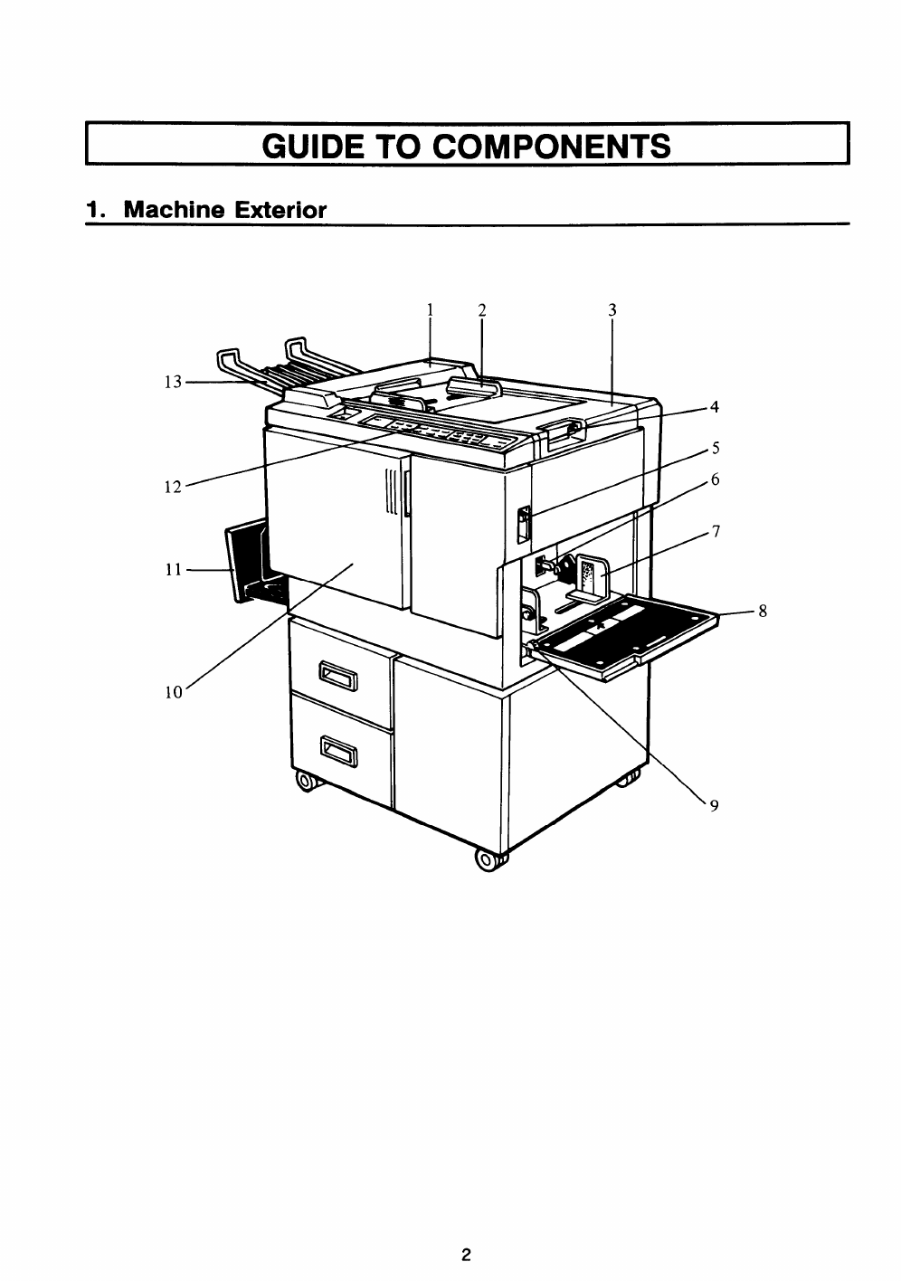
GUIDE TO COMPONENTS
1. Machine Exterior
A!
1111
b‘%Q
12 3
1’5
/6
/7
p–
8
\9
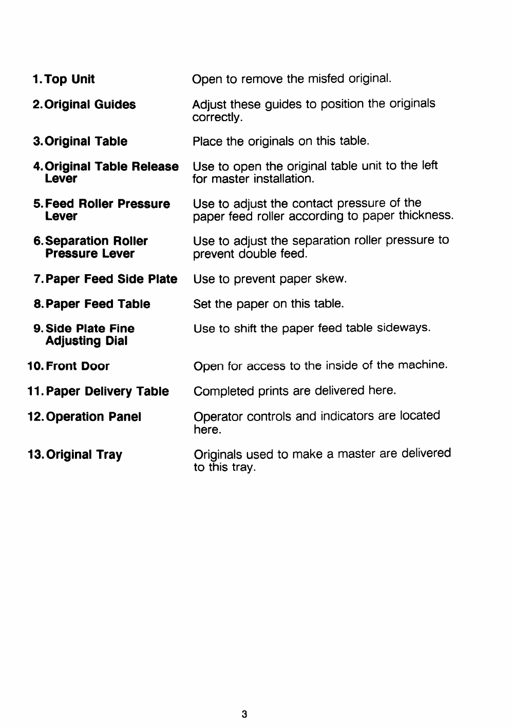
1.Top Unit
2. Original Guides
3.Original Table
4. Original Table Release
Lever
5. Feed Roller Pressure
Lever
6.Separation Roller
Pressure Lever
7. Paper Feed Side Plate
8. Paper Feed Table
9. Side Plate Fine
Adjusting Dial
10. Front Door
11. Paper Delivery Table
12. Operation Panel
13. Original Tray
Open to remove the misfed original.
Adjust these guides to position the originals
correctly.
Place the originals on this table.
Use to open the original table unit to the left
for master installation.
Use to adjust the contact pressure of the
paper feed roller according to paper thickness.
Use to adjust the separation roller pressure to
prevent double feed.
Use to prevent paper skew.
Set the paper on this table.
Use to shift the paper feed table sideways.
Open for access to the inside of the machine.
Completed prints are delivered here.
Operator controls and indicators are located
here.
Originals used to make amaster are delivered
to this tray.
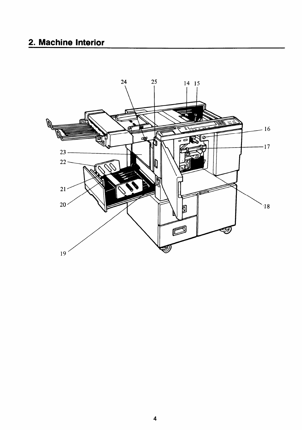
2. Machine Interior
19‘
24 25 14 15
16
17
Ii= \’18
4
14. Master Cut Button Press this button to cut the master paper lead-
15. Pressure Release Lever
16. Drum Rotation Button
17. Drum Unit
18. Ink Holder
19. Main Switch
20. Small Size Paper
Delivery End Plate
(for smaller than
81/2”x 1l“)
21. Paper Delivery End
Plate
(for larger than
81/2” x1l“)
22. Paper Delivery Side
Plate
23. Master Eject Container
Cover
24.Printing Density Select
Switch
25.Master Eject Unit Open
Button
ing edge after installing anew master roll.
Use to install the master roll, or to clean the
thermal head.
Press to replace the drum or to remove misfed
paper.
The master paper is wrapped around this unit.
Set the ink cartridge in this holder.
Use to turn the power on or off.
Use to align the leading edge of small-sized
(less than 81/2” x11”) prints.
Use to align the leading edge of prints larger
than 81/2” x1l“.
Use to align the prints on the paper delivery
table.
Open when removing the master eject box.
Use to select the printing density according to
the type and quality of the original.
Press to remove misfed paper or amisfed
master.
5
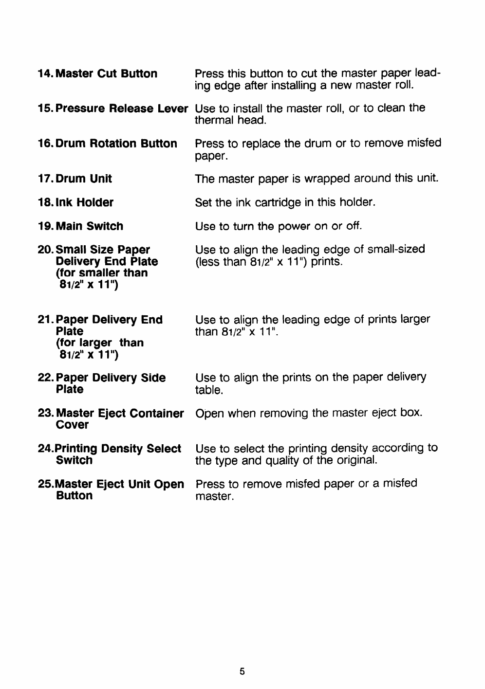
3. Operation Panel
1234
m
r
IA
I
t11
(5
Auto Cycle
OQ
Lower Cornblne 2originals
Q%=%
IO(I 93 75 64
(0000)
1. Reset Key
2. Indicators
3. Auto Cycle Key
4. Reduction Key
5. Image Position
Keys
6. Number Keys
7. Counter
8. Memory Display
9. Print Start Key
10. Master Making Key
11. Proof Key
18 17 16
Press to reset error indicators.
Light or blink when anon-standard condition
occurs within the machine. (See page 42.)
Use to automatically process masters and
make prints.
Press to reduce the image.
Press to shift the image forwards or back-
wards on the print paper.
Press to enter the number of prints.
Displays the number of prints entered. While
printing, it shows the number of uncompleted
prints.
Displays the number of the memory location
that will be used to store the number of
copies. The print number for up to 10 jobs
can be stored at once.
Press to start printing.
Press to make amaster.
Press to make trial prints or extra prints.
6
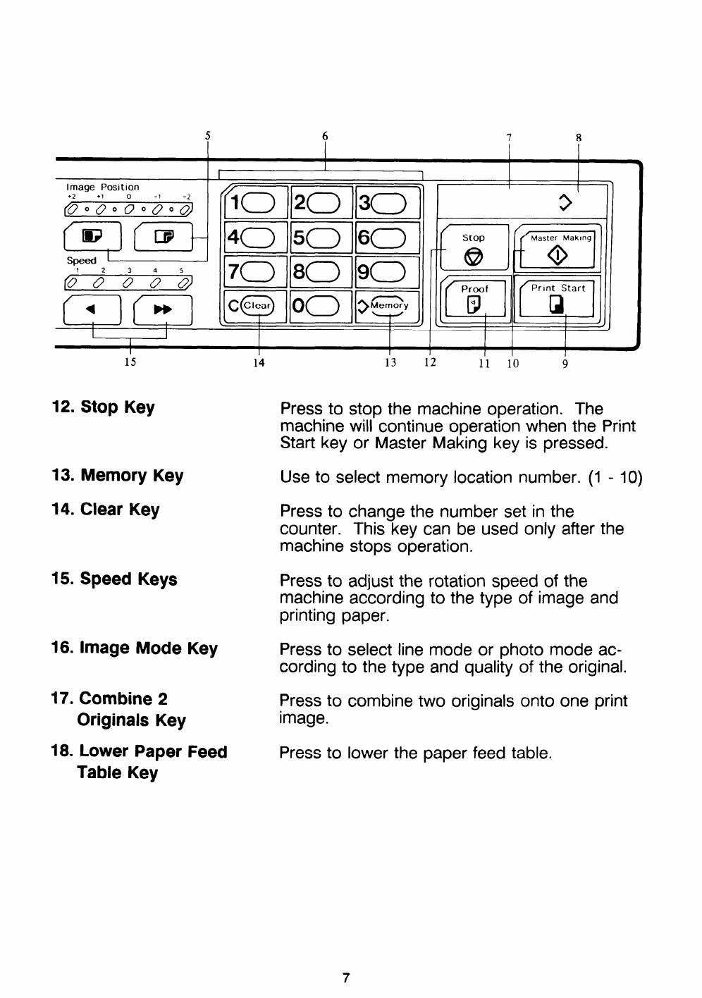
567 8
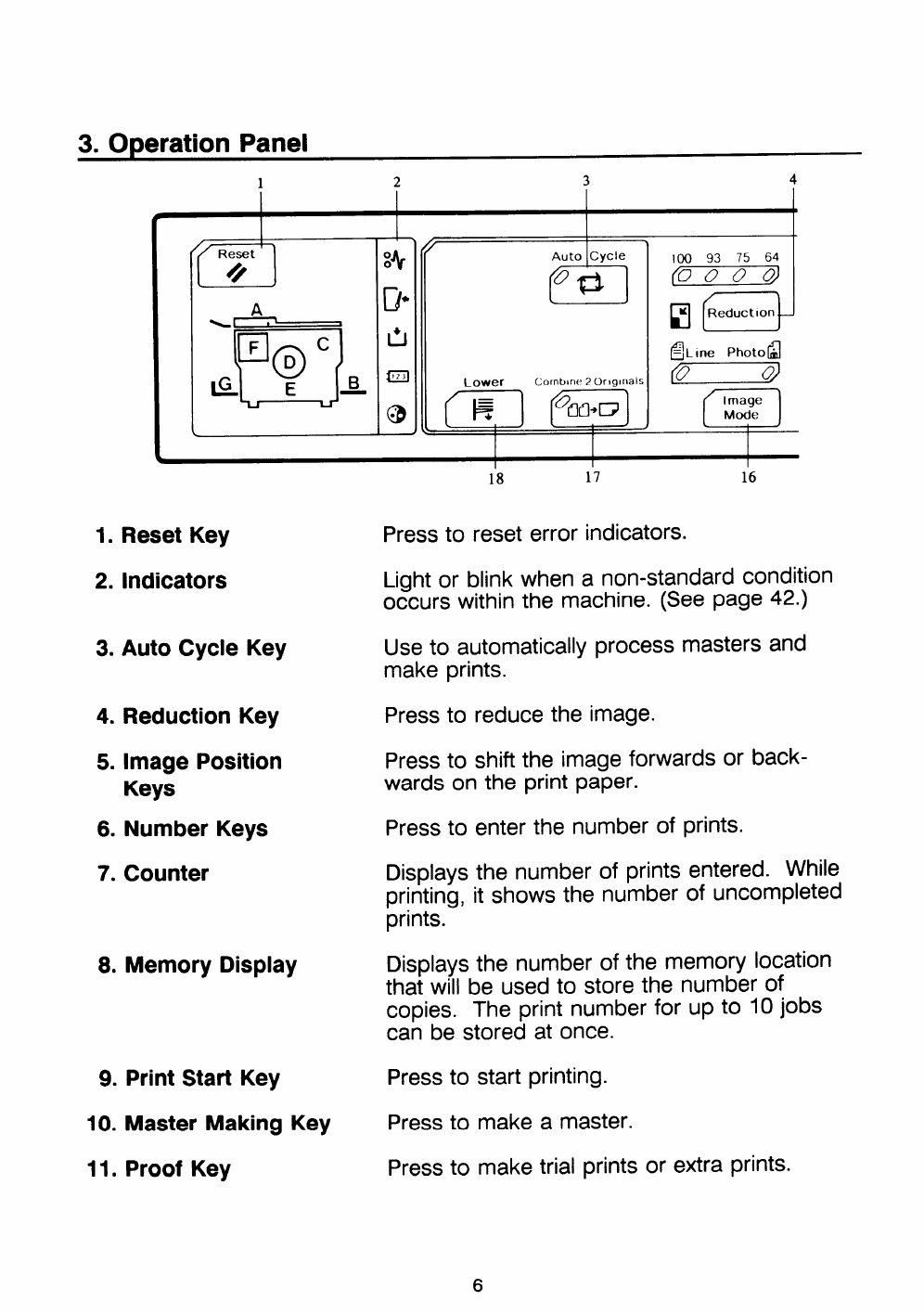
15 14 13 12 11 10 9
12. Stop Key Press to stop the machine operation. The
machine will continue operation when the Print
Start key or Master Making key is pressed.
13. Memory Key Use to select memory location number. (1 -10)
14. Clear Key Press to change the number set in the
counter. This key can be used only after the
machine stops operation.
15. Speed Keys Press to adjust the rotation speed of the
machine according to the type of image and
printing paper.
16. Image Mode Key Press to select line mode or photo mode ac-
cording to the type and quality of the original.
17. Combine 2Press to
Originals Key image.
18. Lower Paper Feed Press to
Table Key
combine two originals onto
lower the paper feed table.
one print
INSTALLATION REQUIREMENTS
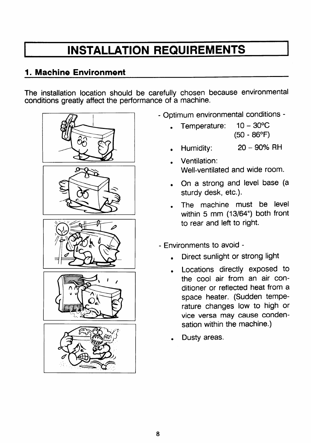
1. Machine Environment
The installation location should be carefully chosen because environmental
conditions greatly affect the performance of amachine.
Iml I-Optimum environmental conditions -
●
●
●
●
●
Temperature: 10 – 30°c
(50 -86”F)
Humidity: 20 – 90% RH
Ventilation:
Well-ventilated and wide room.
On astrong and level base (a
sturdy desk, etc.).
The machine must be level
within 5mm (13/64”) both front
to rear and le~ to right.
-Environments to avoid -
●Direct sunlight or strong light
●Locations directly exposed to
the cool air from an air con-
ditioner or reflected heat from a
space heater. (Sudden tempe-
rature changes low to high or
vice versa may cause conden-
sation within the machine.)
●Dusty areas.
8
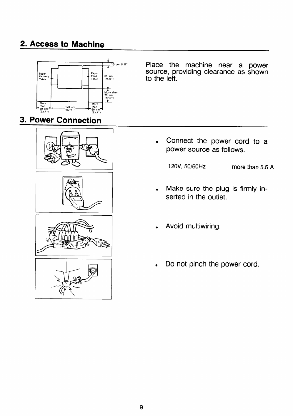
2. Access to Machine
Paper
Del, very
Table
c
than
60 cm”
(23 7“)
~
Paper
Feed
Table
10 cm {4.0”) Place the machine near apower
clearance as shown
Isource, providing
61 cm
(24 O“)
I
to the left.
+
More than
70 cm
(27 6“)
~
(23 7’,1
3. Power Connection
If
.Connect the
power source
120V, 50/60Hz
power cord to a
as follows.
more than 5.5 A
.Make sure the plug is firmly in-
serted in the outlet.
●Avoid multiwiring.
.Do not pinch the power cord.
IDO’S AND DON’TS I
-Operating Cautions -
1. While Printing :
-Do not turn off the main switch.
-Do not unplug the power cord.
-Do not open the front cover.
-Do not move the machine.
2. Keep corrosive liquids, such as acid, off the machine.
3. Do not allow paper clips, staples, or other small objects to fall inside the
machine.
4. Always turn the machine off when you have finished printing for the day.
5. Do not touch print paper if your fingers are wet or oily; fingerprints may
appear on prints.
-General Cautions -
1. Do not modify or replace any parts other than the ones specified in this
manual.
2. When the machine will not be used for long periods, disconnect the
power cord.
3. If the machine must be transported by vehicle, please contact your
dealer.
4. Do not operate the machine with any covers off.
10
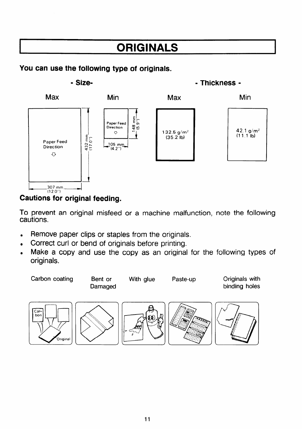
ORIGINALS
You can use the following type of originals.
-Thickness -
Max
Paper Feed
Direction
u
—307 ““—
(120”)
Min
1
7
Paper Feed E:
Direction _
:In
-i
0’
--l
J05 mm
(4 2“)
Max Min
132.5 g/rnz
(35.2 lb)
42.1 glmz
(11.1 lb)
Cautions for original feeding.
TO prevent an original misfeed or amachine malfunction, note the following
cautions.
.Remove paper clips or staples from the originals.
.Correct curl or bend of originals before printing.
.Make acopy and use the
originals.
Carbon coating
LIJn
Car-
bon
]] Y
oOnglnal
Bent or
Damaged
@]
copy as an original for the
With glue Paste-up
O@
.,,,
Q
;,::’:’..:~$
;:? .%5
,,
47
,;.,;:,
?,,,:,...
.:..’..“”...”.. .
. .
.----... ... ,..
.... . -.-...-.$.:
........ ... .. .
. . .. .. ..
..... .. . ..
.....- .- .. .. . .
. ... ... .. ... .. ..
.-. .. ... ,.
following types of
Originalswith
binding holes
11
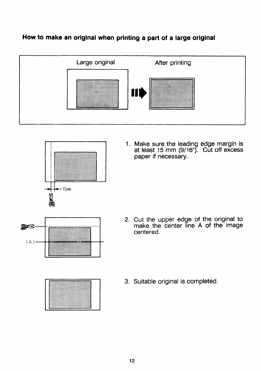
How to make an original when printing apart of alarge original
Large original After printing
1!
+15mm
Iii
1. Make sure the leading edge margin is
at least 15 mm (9/1 6“). Cut off excess
paper .if necessary.
2. Cut the upper edge of the original to
make the center line Aof the image
centered.
3. Suitable original is completed.
12
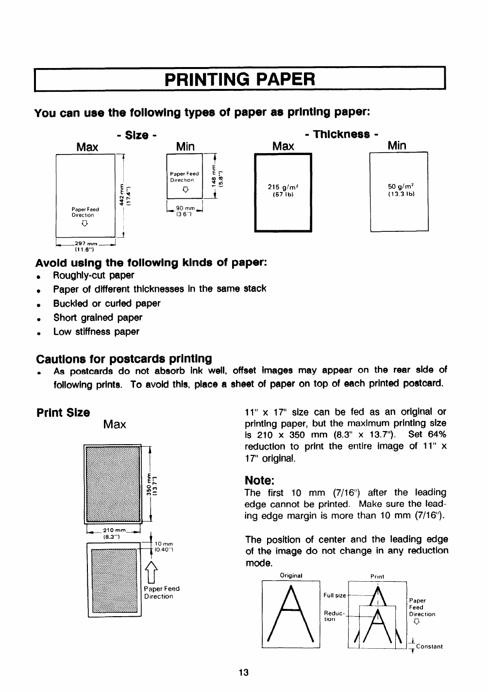
IPRINTING PAPER I
You can use the following types of paper as printing paper:
Paper Feed
Dlrectlon
u
Min
17
J“E
Paper Feed E~
Dlrect!on
uY
Avoid using the foliowing kinds
.Roughly-cut paper
.Paper of different thicknesses In the
.Buckled or curled paper
.Short grained paper
.Low stiffness paper
Cautions for postcards printing
of
Max
215 g/mz
(57 lb)
●As postcards do not absorb ink weii,
foiiowing prints. To avoid this, piace a
Print Size Max
-Thickness -
same stack
Min
r
50 girl+
(13.3 lb)
offset images may appear on the rear side of
sheet of paper on top of each printed postcard.
11” x17“ size can be fed as an original or
printing paper, but the maximum printing size
is 210 x350 mm (8.3” x13.7”). Set 64%
reduction to print the entire image of 11” x
17“ originai.
Note:
The first 10 mm (7/16“) after the ieading
edge cannot be printed. Make sure the lead-
ing edge margin is more than 10 mm (7/16”).
The position of center and the ieading edge
of the image do not change in any reduction
mode.
~;;:,;m_/
r,4 10mm
Original Print
!_.---Y l.J!!L_!j!+Constant -T
13
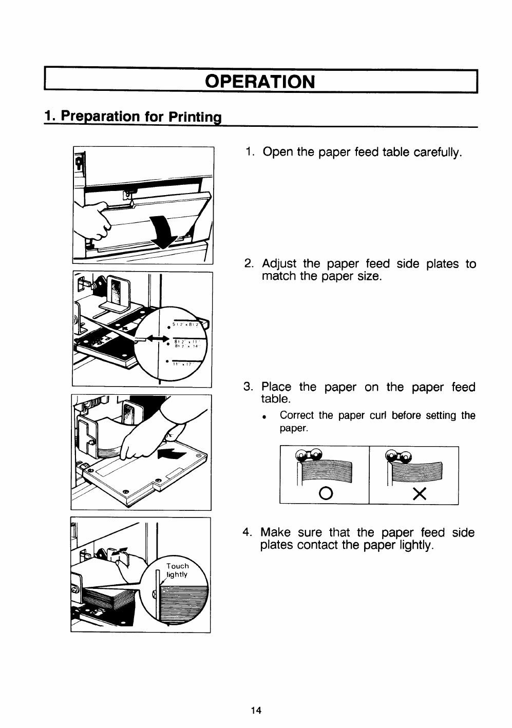
OPERATION
1. Preparation for Printing
1.
2.
Open the paper
Adjust the paper feed
match the paper size.
carefully.
plates to
3. Place the paper on the paper feed
table.
.Correct the paper curl before setting the
paper.
hb
ox
4. Make sure that the paper feed side
plates contact the paper lightly.
14
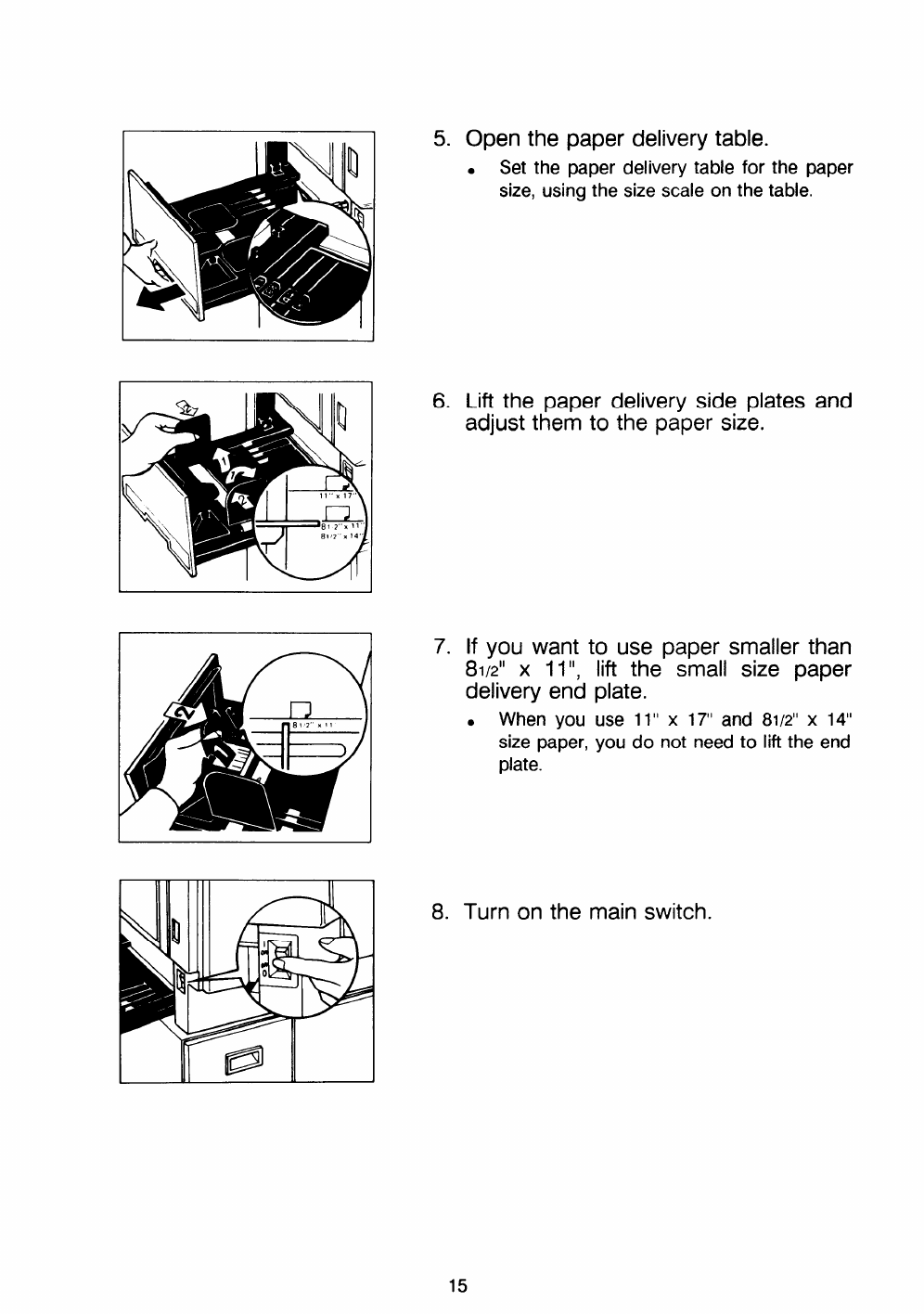
rI5. Open the paper delivery table.
.Set the paper delivery table for the paper
size, using the size scale on the table.
II
I16. Lift the paper delivery side plates and
adjust them to the paper size.
7. If you want to use paper smaller than
81/2” x11”, lift the small size paper
delivery end plate.
.When you use 11” x17“ and 81/2”x14“
size paper, you do not need to lift the end
plate.
8. Turn on the main switch.
15

2. Setting the Originals
I1
J
1. Adjust the original guides to the size
of the original.
2. Insert the original face down on the
original table until it stops.
.Only one original can be set at atime.
3. Select the image
Image Mode keys.
.Use the line mode
printed matter.
mode using the
when the original is
.Use the photo mode when the original
contains photos or colored images.
●The line mode is automatically selected
when the main switch is turned on.
4. If reduced prints are desired, set the
reproduction ratio using the Reduc-
tion key.
.The reduction ratio will change as follows:
93% -75V0 +64%
●11” x17’ original cannot be printed in
100% mode. Select 64Y0.
●100% mode is automatically selected
when the main switch is turned on.
16
3. Printina
1
If -4[ ■1
I
I
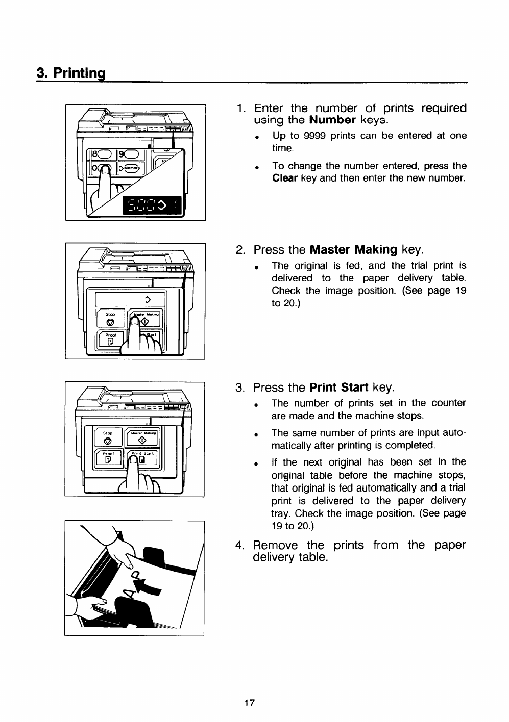
1. Enter the number of prints required
using the Number keys.
.Up to 9999 prints can be entered at one
time.
.To change the number entered, press the
Clear key and then enter the new number.
2. Press the Master Making key.
●The original is fed, and the trial print is
delivered to the paper delivery table.
Check the image position. (See page 19
to 20.)
3. Press the Print Start key.
.The number of prints set in the counter
are made and the machine stops.
.The same number of prints are input auto-
matically after printing is completed.
.If the next original has been set in the
original table before the machine stops,
that original is fed automatically and atrial
print is delivered to the paper delivery
tray. Check the image position. (See page
19 to 20.)
4. Remove the prints from the paper
delivery table.
4. Restoring Paper Feed and Paper Delivery Tabies
1 1
kill I
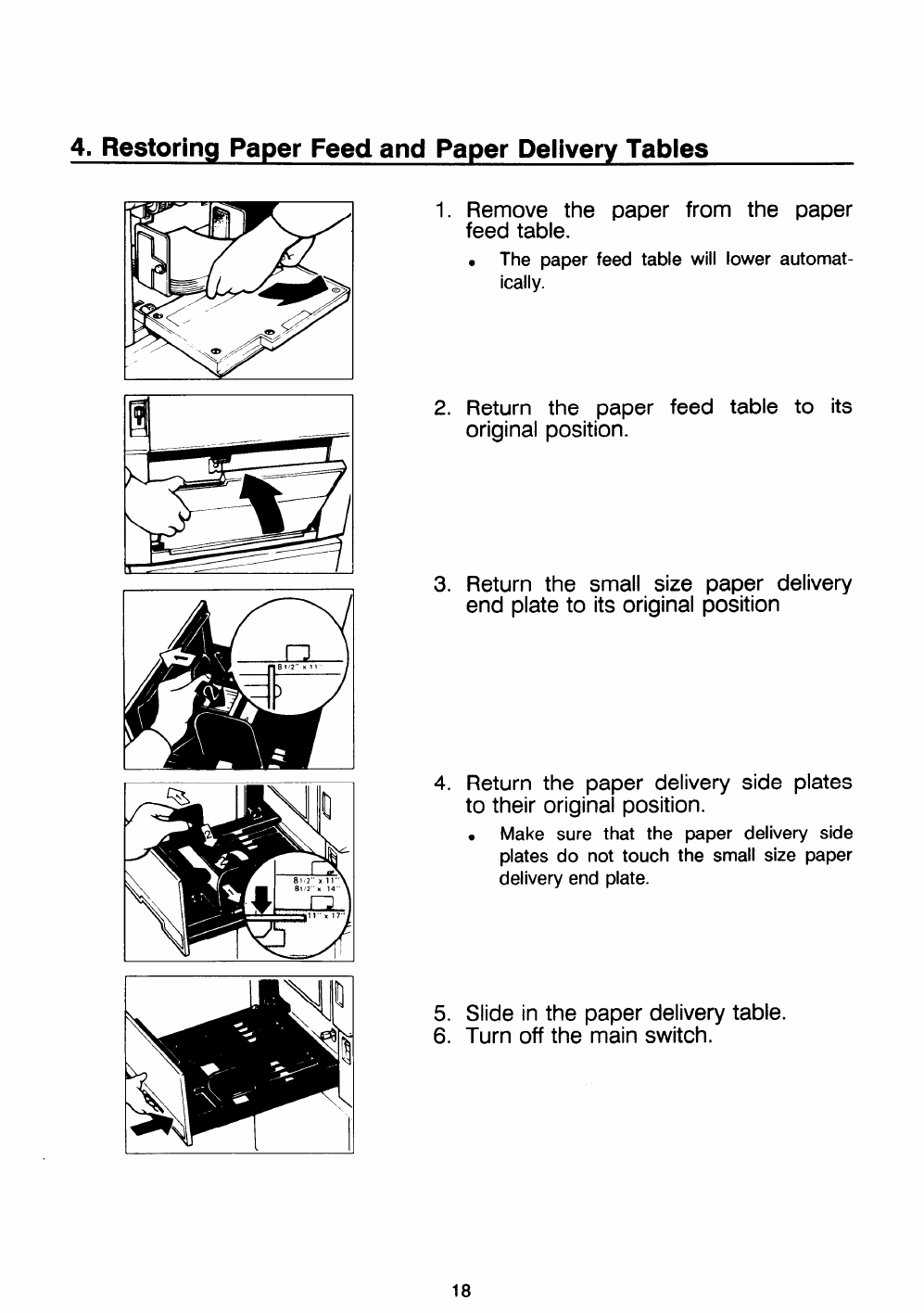
1. Remove the paper from the paper
feed table.
.The paper feed table will lower automat-
ically.
2. Return the paper feed table to its
original position.
3. Return the small size paper delivery
end plate to its original position
4. Return the paper delivery side plates
to their original position.
●Make sure that the paper delivery side
plates do not touch the small size paper
delivery end plate.
5. Slide in the paper delivery table.
6. Turn off the main switch.
11
18

5. Adjusting the Image Position
If the image position is not Correct, acfjust before you start printing.
-Shifting the image position forward
t1 t I
11LI
-Shifting the image position backward
1. Press the left Image Position key.
●When you shift the image forwards, leave
amargin (more than 10 mm/O.40”) at the
leading edge.
2. Press the Proof key. Check the
image position again.
+2 +1 o–’l –2
1. Press the right Image Position key.
2. Press the Proof key. Check the
image position again.
Note:
●The left and right Image Position keys
shift the image about 1mm/O.04° each
time they are pressed.
●When the indicator changes from Oto +1
(-1 ), the image position shifts about
10mm/O.40” (-10mm/PO.40”).
19
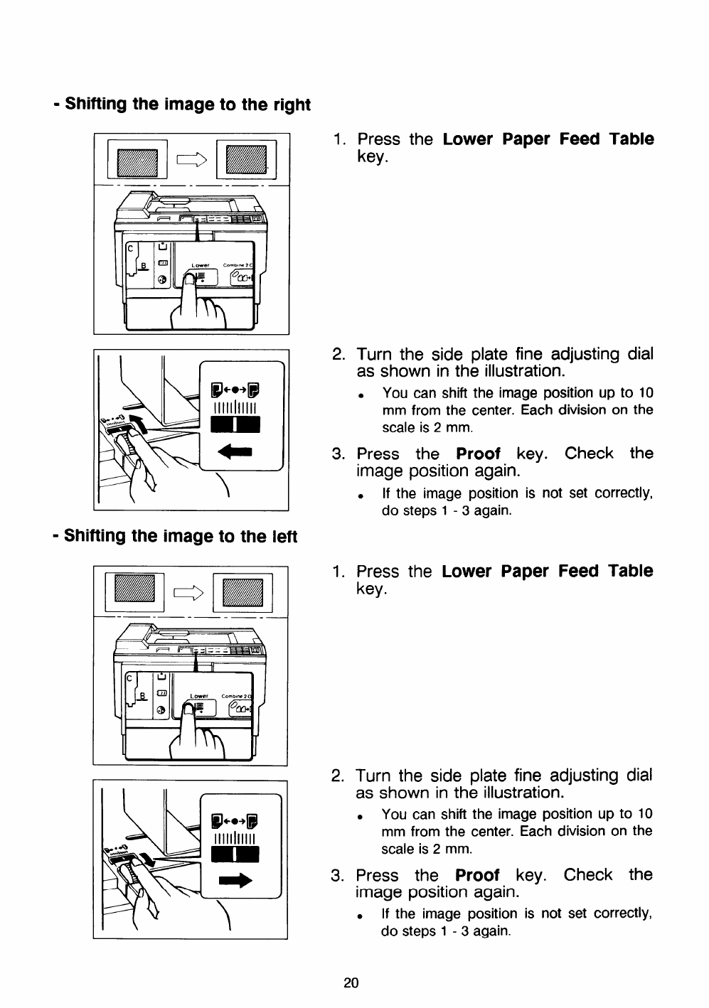
-Shifting the image to the right
m~m
—__.___.-_
-Shifting the image to the left
III (
1.
2.
3.
1.
2.
3.
Press the Lower Paper Feed Table
key.
Turn the side plate fine adjusting dial
as shown in the illustration.
.You can shift the image position up to 10
mm from the center. Each division on the
scale is 2mm.
Press the Proof key. Check the
image position again.
●If the image position is not set correctly,
do steps 1-3 again.
Press the Lower Paper Feed Table
key.
Turn the side plate fine adjusting dial
as shown in the illustration.
.You can shift the image position up to 10
mm from the center. Each division on the
scale is 2mm.
Press the Proof key. Check the
image position again.
. If the image position
do steps 1-3 again.
20
is not set correctly,
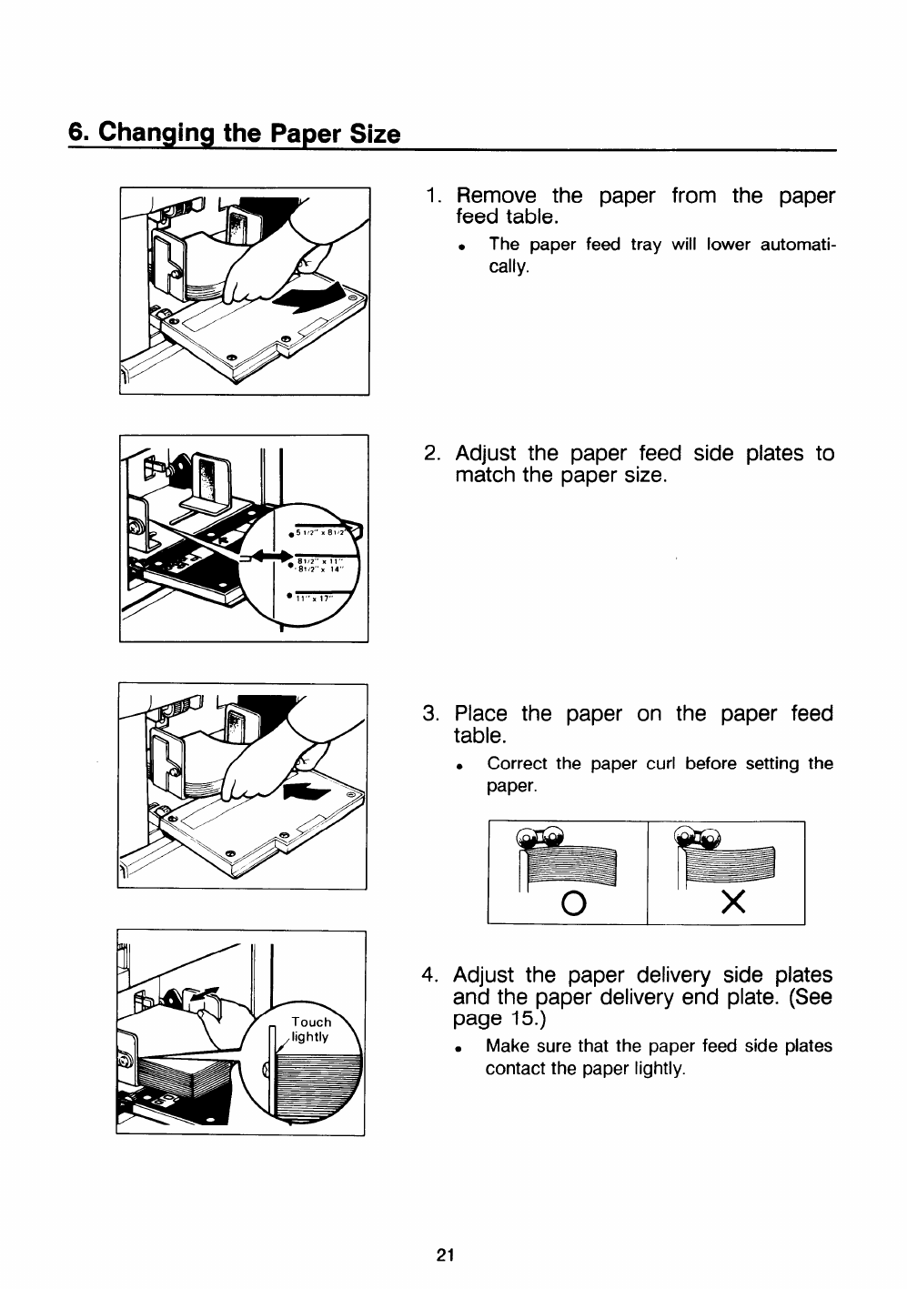
6. Changing the Paper Size
1. Remove the paper from the paper
feed table.
.The paper feed tray will lower automati-
cally.
2. Adjust the paper feed side plates to
match the paper size.
3. Place the paper on the paper feed
table.
.Correct the paper curl before setting the
paper.
!!!!!!s
obx
4. Adjust the paper delivery side plates
and the paper delivery end plate. (See
page 15.)
.Make sure that the paper feed side plates
contact the paper lightly.
21

7. Printing on Thick or Thin Paper
When you make prints on thick or thin paper, do the following steps.
-Printing on thick paper
1. Push down the feed roller pressure
lever.
.Thick paper :132.5 to 215 g/m2 (35.2 to
57 lb)
.In the case of paper smaller than
S1/2’’x8l/2° and heavier than 132.5 g/m2
(35.2 lb), move the feed roller pressure
lever to the standard position.
-Printing on thin paper
2. Push the separation roller pressure
levers up to the thick paper position.
1. Set the side pads (Move the side pad
levers to the right).
.Thin paper: lighter than 51.2 g/m2 (13.61b)
2. Make prints. (See page 14 to 17.)
22
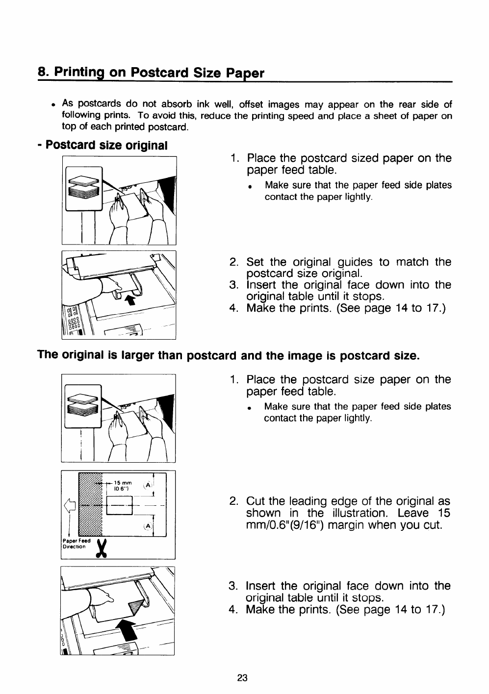
8. Printing on Postcard Size Paper
●AS postcards do not absorb ink well, offset images may appear on the rear side of
following prints. TO avoid th~, reduce the printing speed and place asheet of paper on
top of each printed postcard.
-Postcard size original
1.
—
Place the postcard sized paper on the
I I
2.
3.
4.
paper feed table.
●Make sure that the paper feed side plates
contact the paper lightly.
Set the original guides
postcard size original. to match the
Insert the origin~ face down into the
original table until it stops.
Make the prints. (See page 14 to 17.)
The original is larger than postcard and the image is postcard size.
f1I
Paper Feed
DIrectlo n
x
1. Place the postcard size paper on the
paper feed table.
●Make sure that the paper feed side plates
contact the paper lightly.
2. Cut the leading edge of the original as
shown in the illustration. Leave 15
mm/O.6’’(9/l6”) margin when you cut.
3. Insert the original face down into the
original table until it stops.
4. Make the prints. (See page 14 to 17.)
23
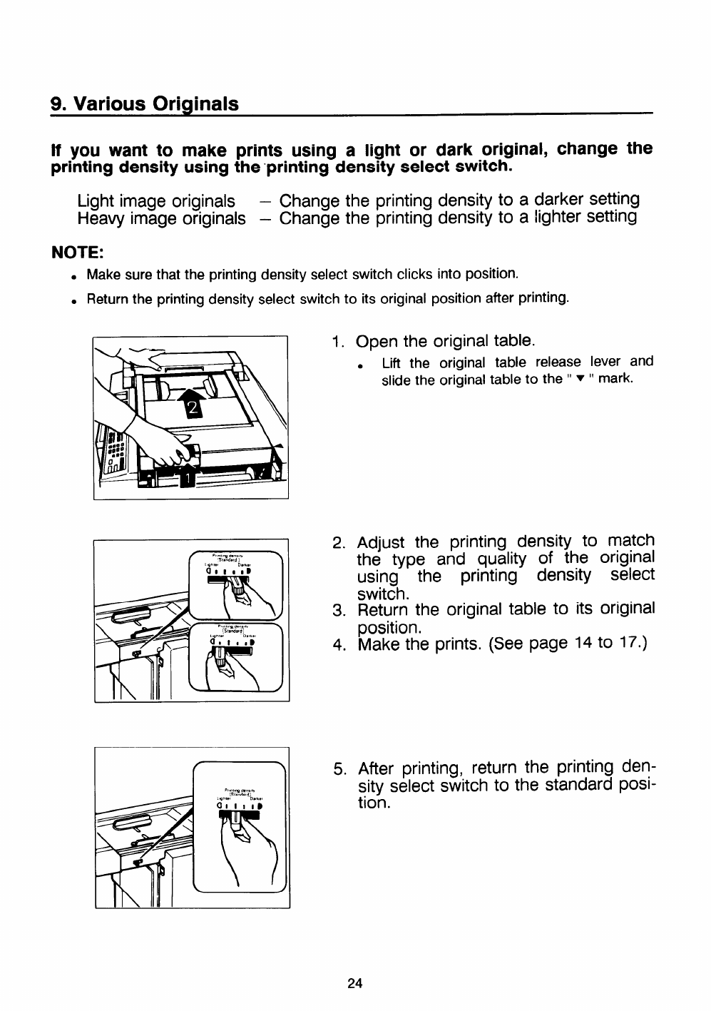
9. Various Originals
If you want to make prints using alight or dark original, change the
printing density using the printing density select switch.
Light image originals –Change the printing density to adarker setting
Heavy image originals –Change the printing density to alighter setting
NOTE:
.Makesurethat the printing density select switch clicks into position.
●Return the printing density select switch to its original position after printing.
I
I%“,,w 0..,,.
W,.nd.rdI
~_~\> 1Y
P,,.,, -6.”,,,, \
WA- ““’’s’’’’’”O”’”’‘
‘m wI
1.
2.
3.
4.
Open the original table.
●Lift the original table release lever and
slide the original table to the “ T“mark.
Adjust the printing density to match
the type and quality of the original
using the printing density select
switch.
Return the original table to its original
position.
Make the prints. (See page 14 to
After printing, return the printing
sity select switch to the standard
tion.
17.)
den-
posi-
24
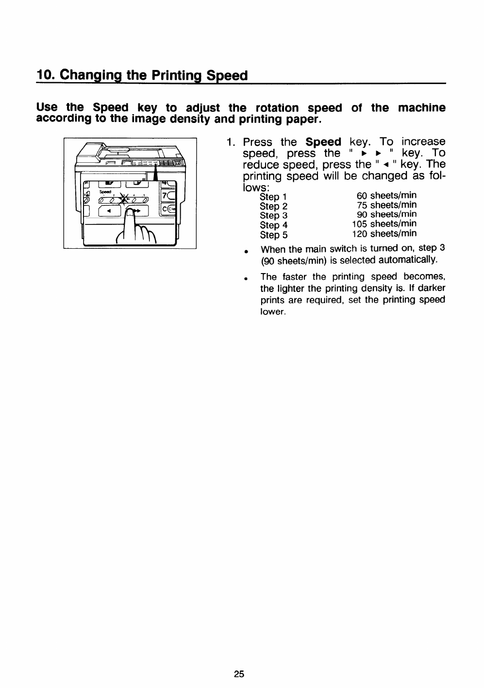
10. Changing the Printing Speed
Use the Speed key to adjust the rotation Speed of the machine
.
according to the image densfiy and
1.
printing paper.
Press the Speed key. To increase
speed, press the “FE“key. To
reduce speed, press the “●“key. The
printing speed will be changed as fol-
lows:
Step 160 sheets/rein
Step 275 sheets/rein
Step 390 sheets/rein
Step 4105 sheets/rein
Step 5120 sheets/rein
.When the main switch is turned on, step 3
(9o sheets/rein) issd@d a@OrnatiCallY-
SThe faster the printing speed becomes,
the lighter the printing density is. If darker
prints are required, set the printing speed
lower.
25
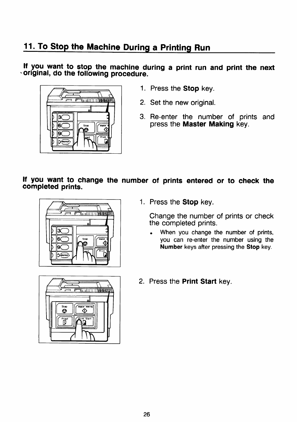
11. To Stop the Machine During aPrinting Run
[f you want to stop the machine during aprint run and print the next
-original, do the following procedure.
1. Press the Stop key.
2. Set the new original.
3. Re-enter the number of prints and
press the Master Making key.
If you want to change the number of prints entered or to check the
completed prints.
1. Press the Stop key.
Change the number of prints or check
the completed prints.
.When you change the number of prints,
you can re-enter the number using the
Number keys after pressing the Stop key.
2. Press the Print Start key.
26
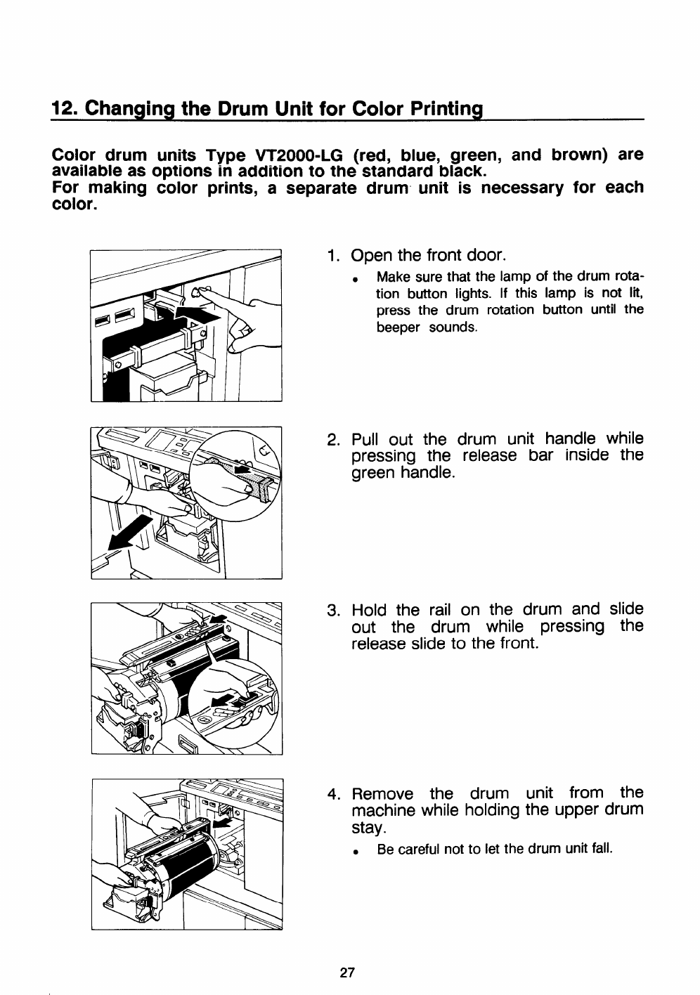
12. Changing the Drum Unit for Color Printing
Color drum units Type VT2000-LG (red, blue, green, and brown) are
available as options in addition to the standard black.
For making color prints, aseparate drum unit is necessary for each
color.
1. Open the front door.
●Make sure that the lamp of the drum rota-
tion button lights. If this lamp is not lit,
press the drum rotation button until the
beeper sounds.
2. Pull out the drum unit handle while
pressing the release bar inside the
green handle.
3. Hold the rail on the drum and slide
out the drum while pressing the
release slide to the front.
4. Remove the drum unit from the
machine while holding the upper drum
stay.
●Be careful not to let the drum unit fall.
27
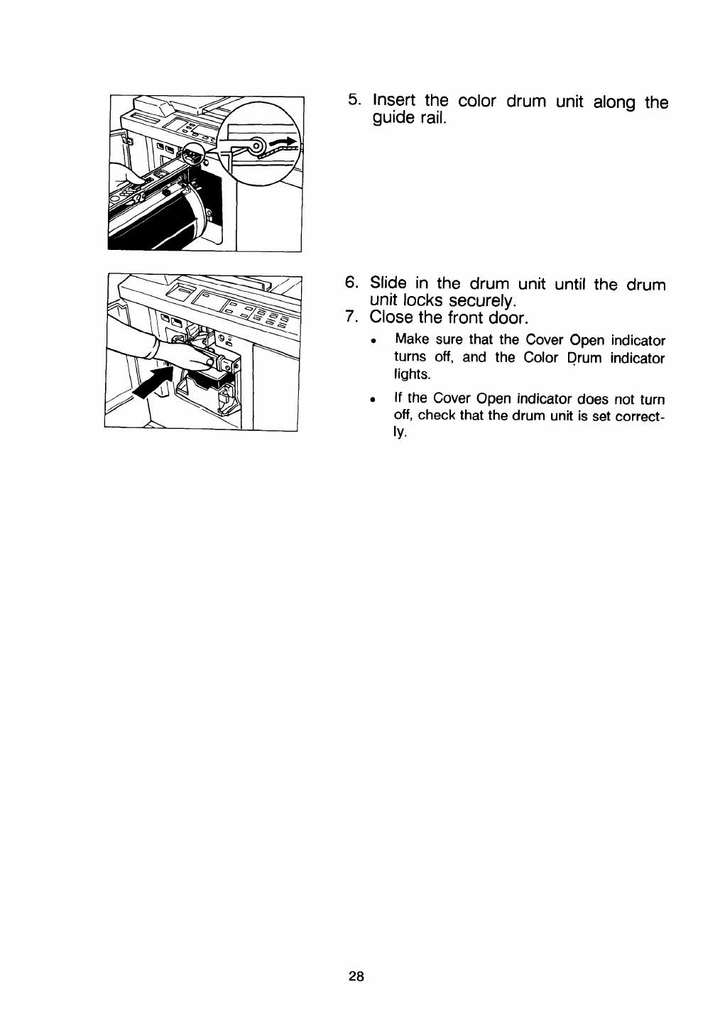
~Insert the color drum unit alona the
guide rail. w-—
6.
7.
Slide in the drum unit until the drum
unit locks securely.
Close the front door.
.Make sure that the Cover Open indicator
turns off, and the Color Drum indicator
lights.
.If the Cover Open indicator does not turn
off, check that the drum unit is set correct-
ly.
28
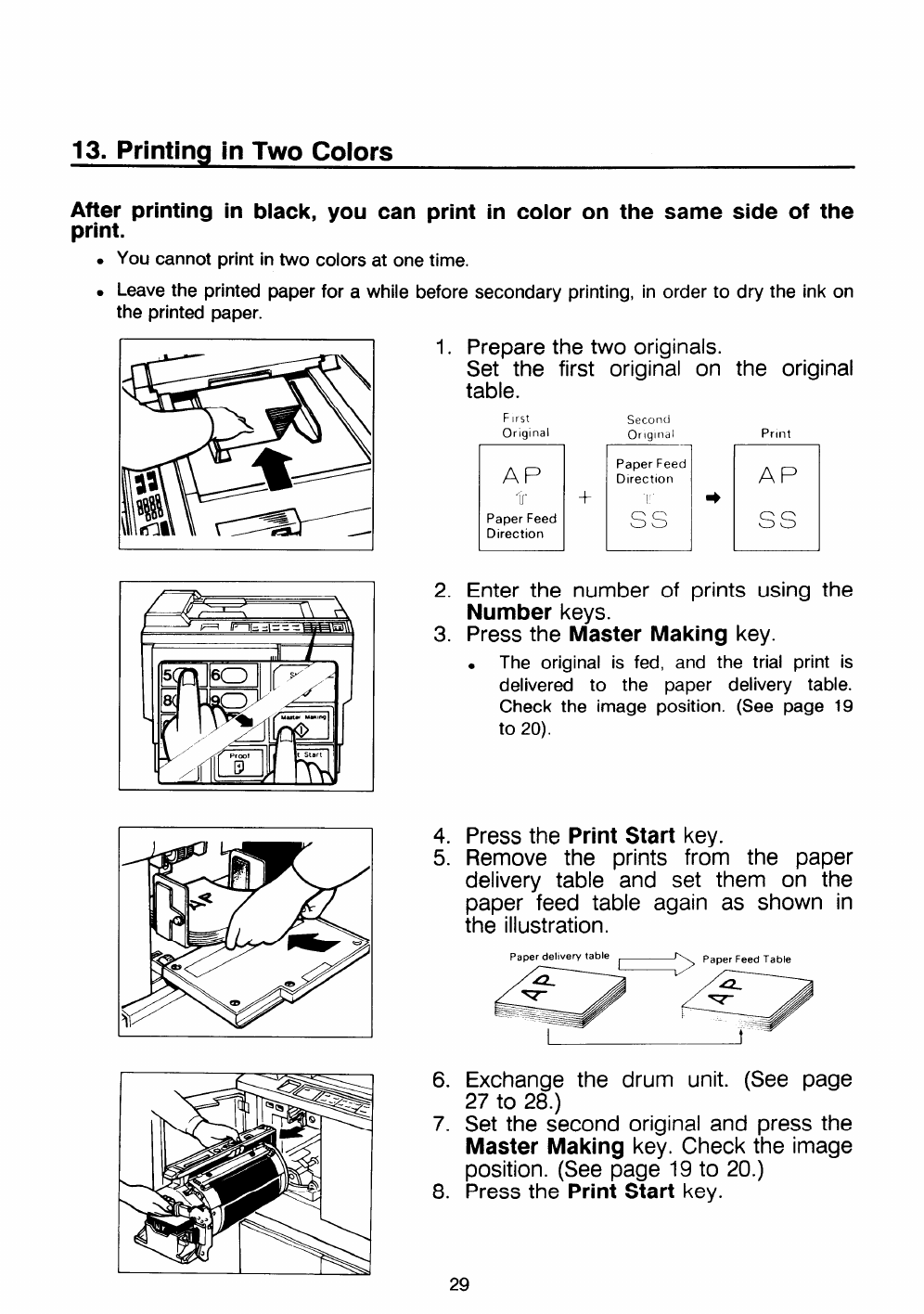
13. Printing in Two Colors
After printing in black, you can print in color on the same side of the
print.
●
●
You cannot print in two colors at one time.
Leave the printed paper for awhile before secondary printing, in order to dry the ink on
the printed paper.
1.
2.
3.
4.
5.
6.
7.
8.
Prepare the two originals.
Set the first original on the original
table.
F[rst Second
Orlglnal orlglndl
H+m”
Print
AP
Ss
Enter the number of prints using
Number keys.
Press the Master Making key.
the
●The original is fed, and the trial print is
delivered to the paper delivery table.
Check the image position. (See page 19
to 20).
Press the Print Start key.
Remove the prints from the paper
delivery table and set them on the
paper feed table again as shown in
the illustration.
Paper delwew table
eye
Exchange the drum unit. (See page
27 to 28.)
Set the second original and press the
Master Making key, Check the image
position. (See page 19 to 20.)
Press the Print Start key.
29
SPECIAL FUNCTIONS
t
1. Group Printing from the Same Original
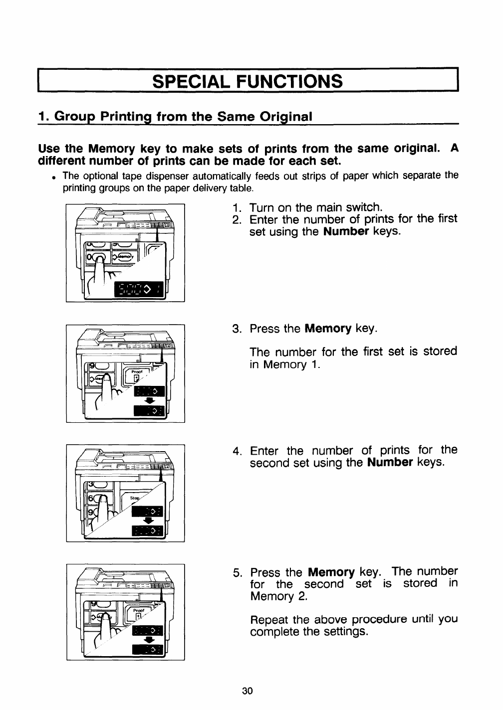
Use the Memory key to make sets of prints from the same original. A
different number of prints can be made for each set.
●The optional tape dispenser automatically feeds out strips of paper which separate the
printing groups on the paper delivery table.
L.—F--L--I
~‘n
Ii==! Ir-11= =\=== mEI\
1.
2. Turn on the main switch.
Enter the number of prints for the first
set using the Number keys.
3. Press the Memory key.
The number for the first set is stored
in Memory 1.
4. Enter the number of prints for the
second set using the Number keys.
5. Press the Memory key. The number
for the second set is stored in
Memory 2.
Repeat the above procedure until you
complete the settings.
30
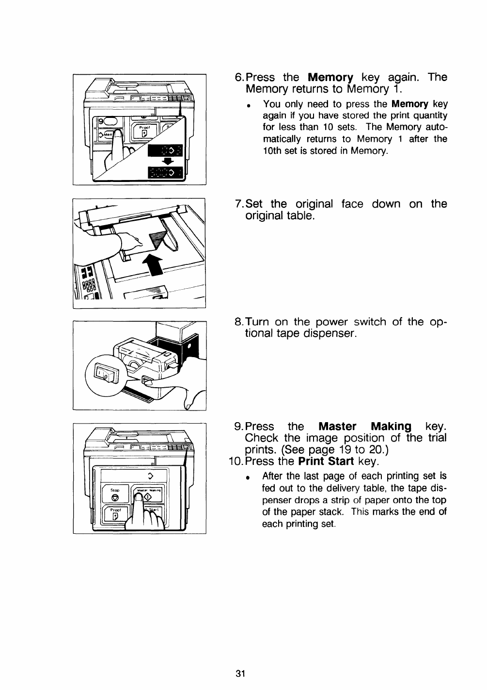
6. Press the Memory key again. The
Memory returns to Memory 1.
.You only need to press the Memory key
again if you have stored the print quantity
for less than 10 sets. The Memory auto-
matically returns
10th set is stored
7. Set the original
original table.
to Memory 1after the
in Memory.
face down on the
II
8.Turn on the power switch of the op-
tional tape dispenser.
9. Press the Master Making key.
Check the image position of the trial
prints. (See page 19 to 20.)
10. Press the Print Start key.
●After the last page of each printing set is
fed out to the delivery table, the tape dis-
penser drops astrip of paper onto the top
of the paper stack. This marks the end of
each printing set.
31
2. Combine 2Oriainals
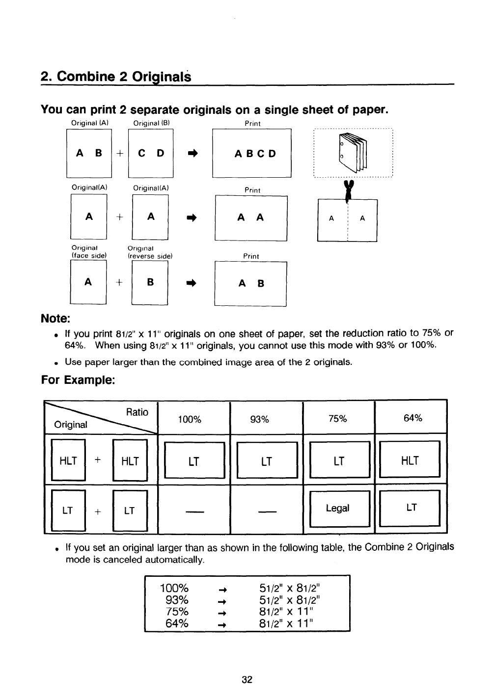
YOU can print 2separate Originals masingle sheet of paper.
Original (A)
El
AB+
Orlglnal(A)
El
A+
Onglnal
(face side)
El
A+
Original (B)
CD
Orlglnal(A)
E!
A
Orlglnal
(reverse side)
El
B
Print t
1....................... .... J
Print
n
AB
,I
●if you print 81/2” x11” originals on one sheet of paper, set the reduction ratio to 75% or
640A. When using 81/2”x11” originals, you cannot use this mode with 93?40or 100Y0i
.Use paper larger than the combined image area of the 2originals.
For Example:
Ratio
Original 100% 93% 75$Z0 64%
~~1 ~1 ~1 ~1
El+El - - @~
●Hyou set an original larger than as shown in the following table, the Combine 2originals
mode is canceled automatically.
100$%0 51/2” x81/2”
93% :51/2” x81/2”
75Y0 +81/2” x11“
64% +81/2” x11“
32
1.
2.
3.
4.
5.
6.
7.
8.
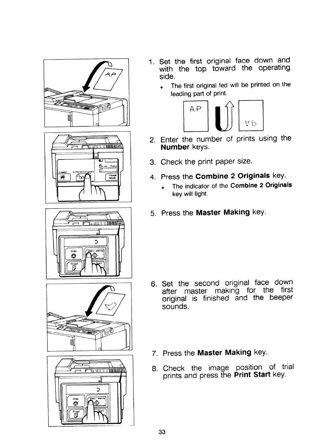
Set the first original face down and
with the top toward the operating
side.
●The first original fed will be printed on the
leading part of print.
Enter the number of prints using the
Number keys.
Check the print paper size.
Press the Combine 2Originals key.
.The indicator of the Combine 2Originals
key will light.
Press the Master Making key.
Set the second original face down
after master making for the first
original is finished and the beeper
sounds.
Press the Master Making key.
Check the image position of trial
prints and press the Print Start key.
33
3. Various Run Lengths Using the Same Master
fIll I I
I
!lm
~(m,
[i]Prcd Pr,”t
start
19ci
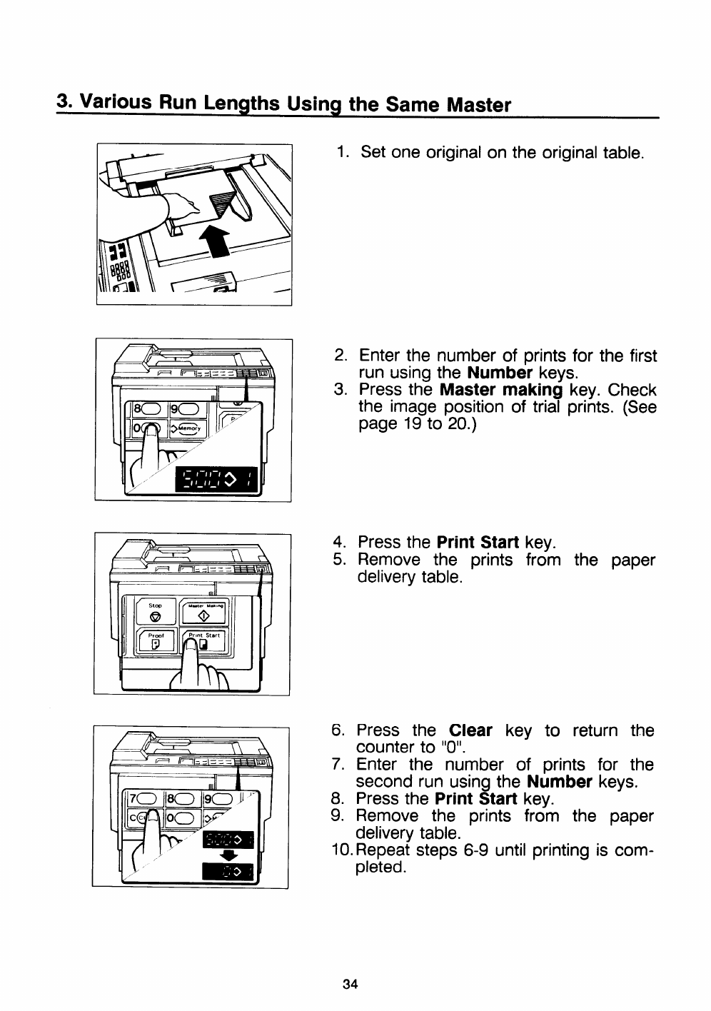
1. Set one original on the original table.
2. Enter the number of prints for the first
run using the Number keys.
3. Press the Master making key. Check
the image position of trial prints. (See
page 19 to 20.)
4. Press the Print Start key.
5. Remove the prints from the paper
delivery table.
6. Press the Clear key to return the
counter to “O”.
7. Enter the number of prints for the
second run using the Number keys.
8. Press the Print Start key.
9. Remove the prints from the paper
delivery table.
10. Repeat steps 6-9 until printing is com-
pleted.
34

4. Photo Mode Printing
When printing aphotograph or acolor original, select Photo Mode.
Original
.Striped patterns may
.When using originals
Photo mode Line mode
occur when meshed originals are printed.
with letters and photos, the image of the letters will be light.
l—
1(I311I
1. Press the Image Mode key to select
Photo mode.
2, Press the Master Making key.
35
REPLENISHING SUPPLIES
1. Loadina Pa~er
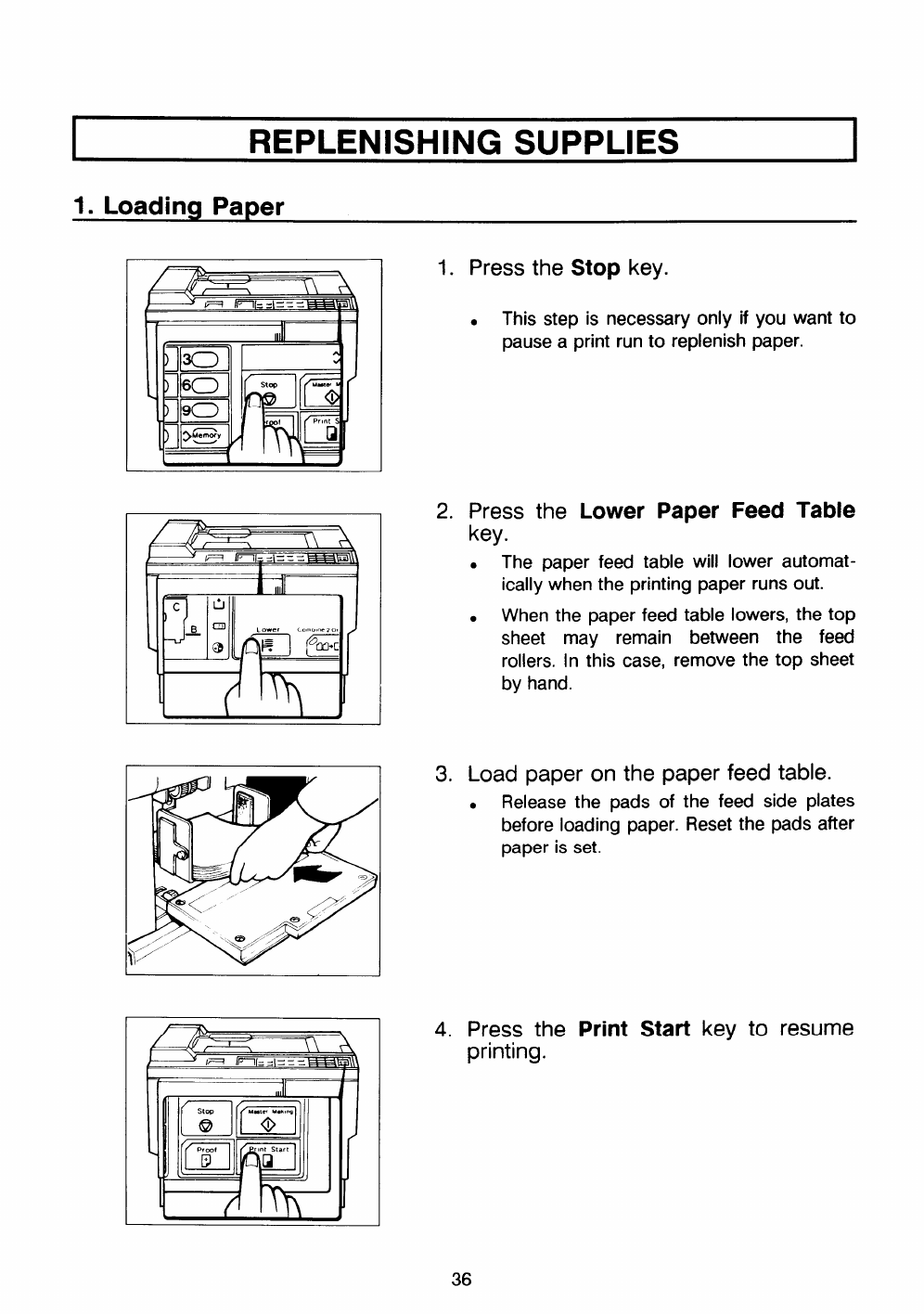
1. Press the Stop key.
.This step is necessary only if you want
pause aprint run to replenish paper.
2. Press the Lower Paper Feed Table
key.
●The paper feed table will lower automat-
ically when the printing paper runs out.
●When the paper feed table lowers, the top
sheet may remain between the feed
rollers. In this case, remove the top sheet
by hand.
3. Load paper on the paper feed table.
●Release the pads of the feed side plates
before loading paper. Reset the pads after
paper is set.
4. Press the Print Start key to resume
printing.
36
2. Supplying Ink
—
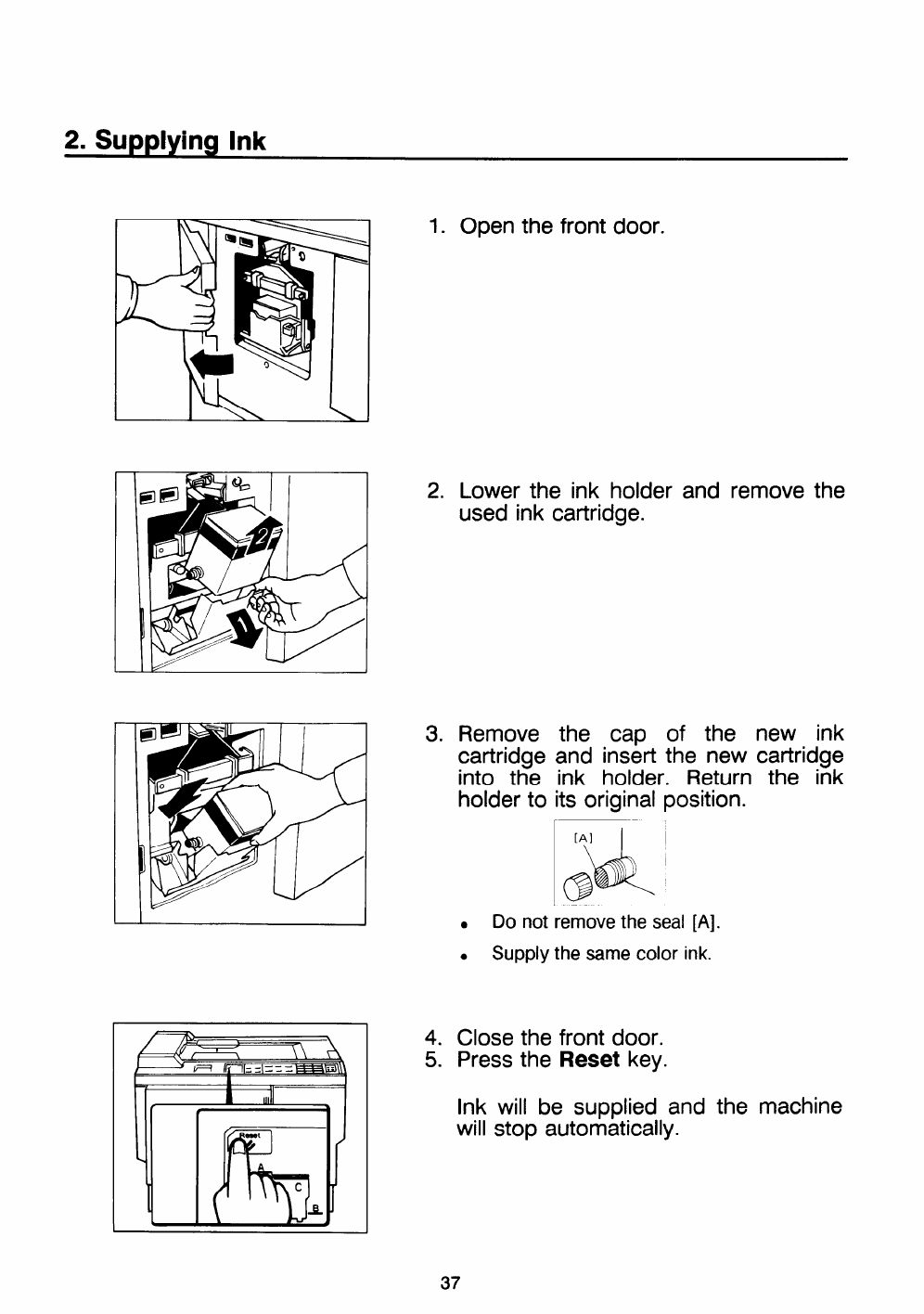
1. Open the front door.
2. Lower the ink holder and remove the
used ink cartridge.
3. Remove the cap of the new ink
cartridge and insert the new cartridge
into the ink holder. Return the ink
holder to its original position.
r
I
I
,
.Do not remove the seal [A].
.Supply the same color ink.
4. Close the front door.
5. Press the Reset key.
Ink will be supplied and the machine
will stop automatically.
37
3. Master Roll Replacement
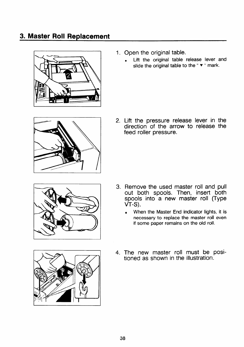
I1. Open the original table.
●Lift the original table release lever and
slide the original table to the “ Y“mark.
2. Lift the pressure release lever in the
direction of the arrow to release the
feed roller pressure.
3. Remove the used master roll and pull
out both spools. Thenj insert both
spools into anew master roll (Type
VT-s).
.When the Master End indicator lights, it is
necessary to replace the master roll even
if some paper remains on the old roll.
4. The new master roll must be posi-
tioned as shown in the illustration.
38
/
/
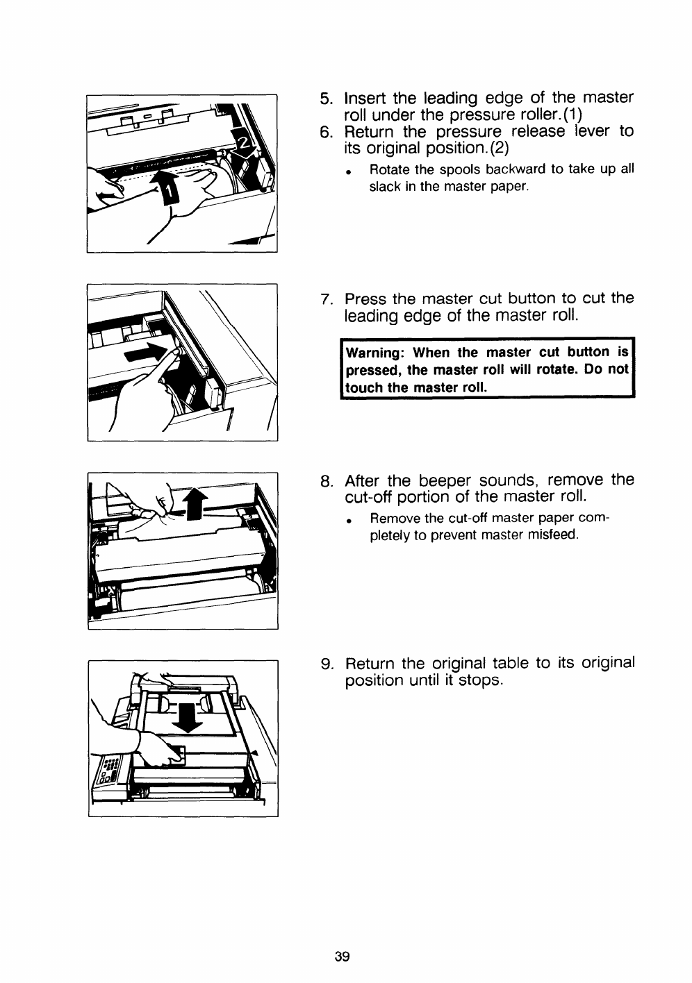
5. Insert the leading edge of the master
roll under the pressure roller. (1)
6. Return the pressure release lever to
its original position. (2)
●Rotatethe spools backward to take up all
slack in the masterpaper.
7. Press the master cut button to cut the
leading edge of the master roll.
IWarning: When the master cut button is
pressed, the master roll will rotate. Do not
touch the master roll. I
8. After the beeper sounds, remove the
cut-off portion of the master roll.
●Remove the cut-off master paper com-
pletely to prevent master misfeed.
9. Return the original table to its original
position until it stops.
39
MAINTENANCE
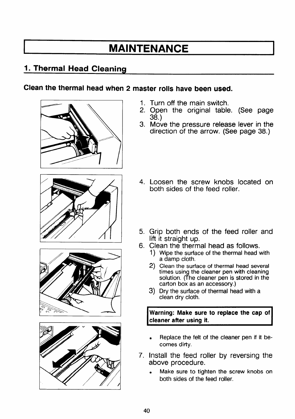
1. Thermal Head Cleaning
Clean the thermal head when 2master rolls have been used.
I
II
1. Turn off the main switch.
2. Open the original table. (See page
38.)
3. Move the pressure release lever in the
direction of the arrow. (See page 38.)
4. Loosen the screw knobs located on
both sides of the feed roller.
5. Grip both ends of the feed roller and
lift it straight up.
6. Clean the thermal head as follows.
I) Wipethe surfaceof the thermal headwith
adamp cloth.
2) Cleanthe surfaceof thermal head several
times usingthe cleanerpen with cleaning
solution. (The cleaner pen is stored in the
carton box as an accessory.)
3) Dry the surface of thermal head with a
clean dry cloth.
IWarning: Make sure to replace the cap of
cleaner after using it.
.Replace the felt of the cleaner pen if it be-
comes ditty.
7. Install the feed roller
above procedure.
.Make sure to tighten
both sidesof the feed
by reversing the
the screw knobs on
roller.
40
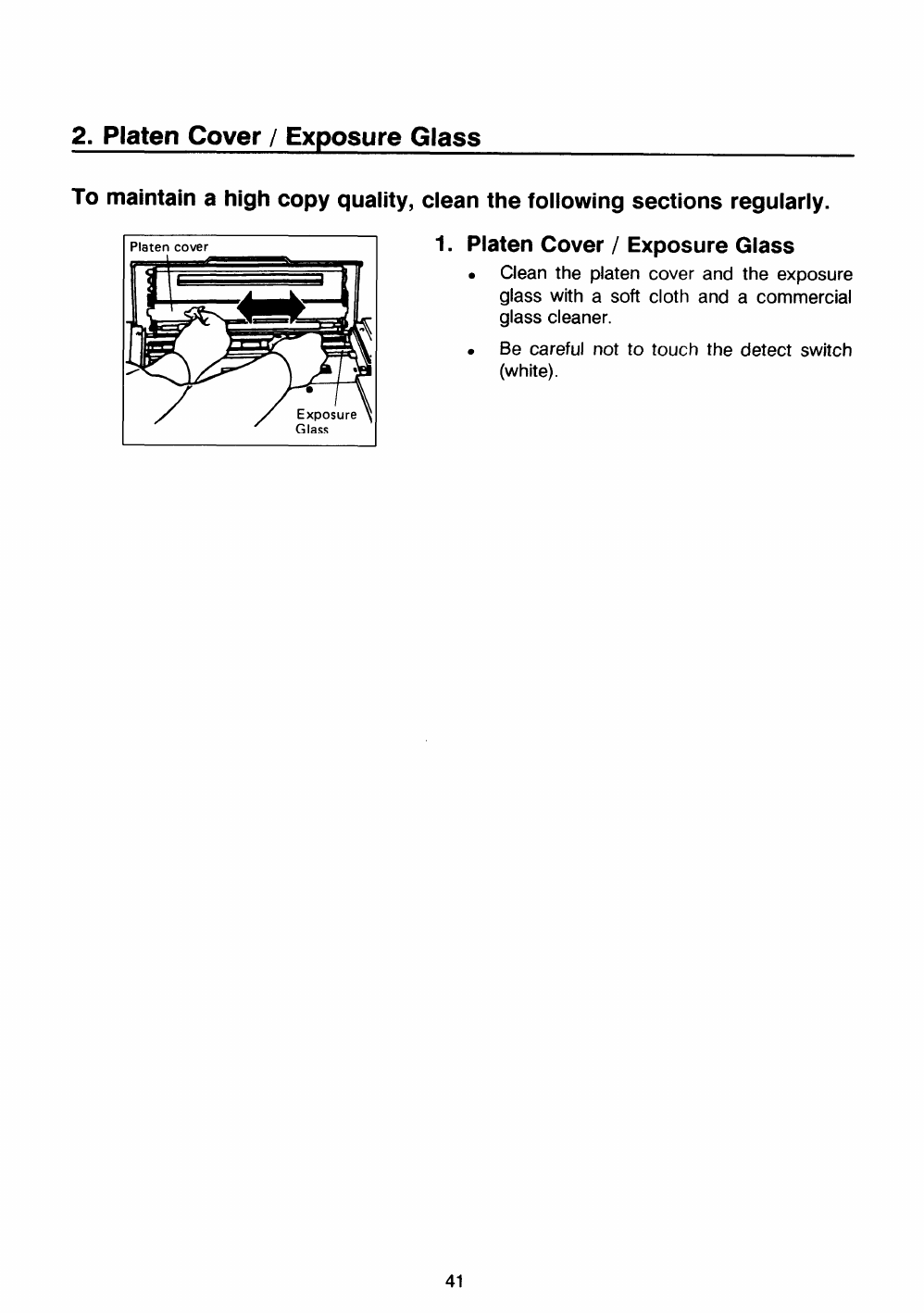
2. Platen Cover /Exposure Glass
To maintain ahigh copy quality, clean the following sections regularly.
Platen cover
I
7rli
//Exposure ~
Glass
1. Platen Cover /Exposure Glass
.Clean the platen cover and the exposure
glass with asoft cloth and acommercial
glass cleaner.
.Be careful not to touch the detect switch
(white).
41
ITROUBLESHOOTING I
1. Indicators
[f amalfunction or amisfeed occurs within the machine, the following indicators will light.
-Check the misfeed or malfunction location.
If aservice code
representative.
Open the top unit cover, remove original and reset. (See page 43.)
Remove the jammed paper and press the Reset key. (See page 44.)
Remove the jammed master and pressthe Resetkey. (Seepage 45.)
Open the master eject unit and remove any jammed paper, then press
the Reset key. If the paper is stuck to the drum, pull out the drum unit
until the drum unit hits the drum stopper, and remove the jammed paper
from the drum. (See page 46.)
1. If the paper is stuck to the drum, pull out the drum unit until the drum
unit hits the drum stopper, and remove the jammed paper from the
drum.
2. If the jam is in the paper feed section, the jammed paper may be
cleared at either the paper entrance or the paper exit side.
(See page 47.)
Open the master eject unit and remove the jammed master. Press Reset
key. If the jammed master is stuck to the drum, pull out the drum unit
and remove the misfed master. (See page 48.)
Open the master eject unit and remove the jammed paper. Press Reset
key. (See page 48.)
Check that the original is correctly placed and that the counter is set for
the required number of copies. (See page 49.)
Load paper. (See page 49.)
Load new master roll. (See page 49.)
Load new ink cartridge. (See page 50.)
1. Remove the used masters inside the master eject box.
2. Make sure the master eject box is replaced correctly. (See page 50.)
Check the setting of the original table, the front cover, the master eject
unit,the drum, the paperfeed table, and the top unit. (Seepage 51.)
Color drum is installed.(See page 51.)
Setthe key counter. (Seepage 51.)
(EO1–E08) is displayed in the counter, please contact your service
42
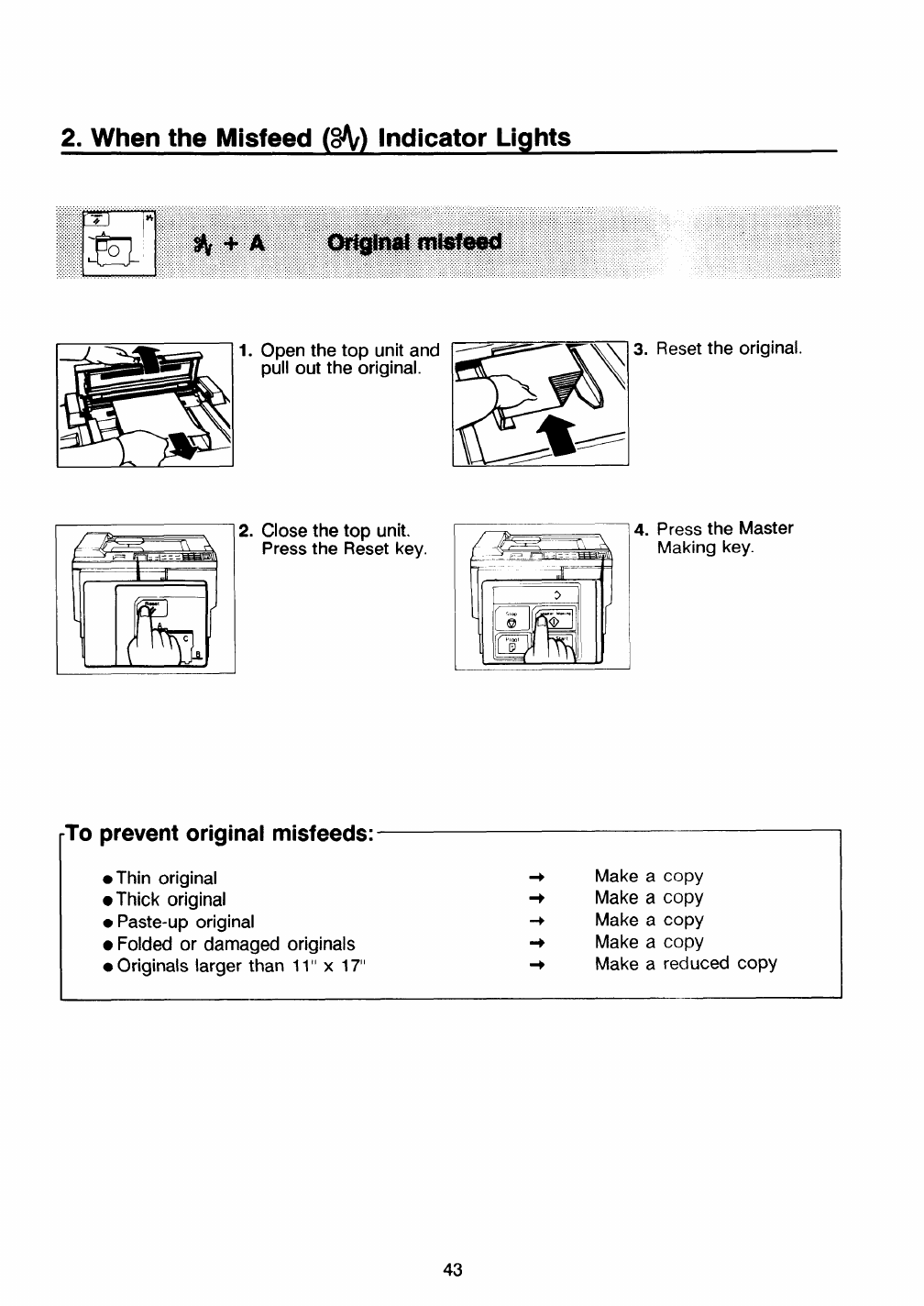
2. When the Misfeed (~) Indicator Lights
1. Open the top unit and
pull out the original.
kf- 1
Z. Close the top unit.
Press the Reset key.
3.
4.
Reset the original.
Press the Master
Making key.
prevent original misfeeds:
●Thin original +Make acopy
●Thick original +Make acopy
●Paste-up original +Make acopy
●Folded or damaged originals +Make acopy
●Originals larger than 11” x17“ +Make areduced copy
43
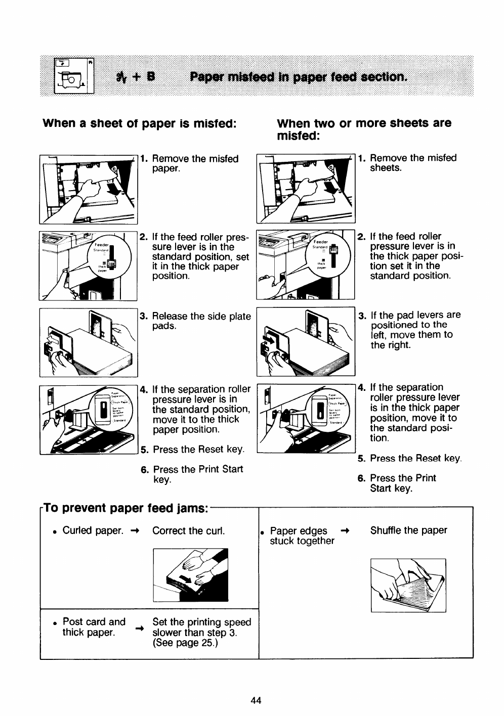
When asheet of paper is misfed: When two or
misfed: more sheets are
Remove the misfed
paper. Remove the misfed
sheets.
1.
-1
11.
2.If the feed roller pres-
sure lever is in the
standard position, set
it in the thick paper
position.
If the feed roller
pressure lever is in
the thick paper posi-
tion set it in the
standard position.
3. 3.Release the side plate
pads. If the pad levers are
positioned to the
left, move them to
the right.
4.
5.
6.
If the separation
roller pressure lever
is in the thick paper
position, move it to
the standard posi-
tion.
If the separation roller
pressure lever is in
the standard position,
move it to the thick
paper position.
4.
Press the Reset key. Press the Reset key.
5.
6.
Press the Print Start
key. Press the Print
Start key.
To
●
prevent paper feed jams:
Correct the curl.
Curled paper. +,Paper edges ~Shuffle the paper
stuck together
.Post card and Set the printing speed
thick paper. +slower than step 3.
(See page 25.)

1.
2.
3.
Slide the original table
to the left while pull-
ing up original table
release lever.
Remove the misfed ~
master.
PI
\\
Slide the original table
to the original position. *+
If you could not
remove the misfed
master in step 2, take
out the drum and
remove the misfed
master from inside.
(See page 27 and 28.) I
5.
6.
I
I7.
8.
Open the top unit
and slowly but firm-
ly pull out the
original.
Re-insert the
original after clos-
ing the top unit.
Press he Reset key.
Press the Master
Making key.
45
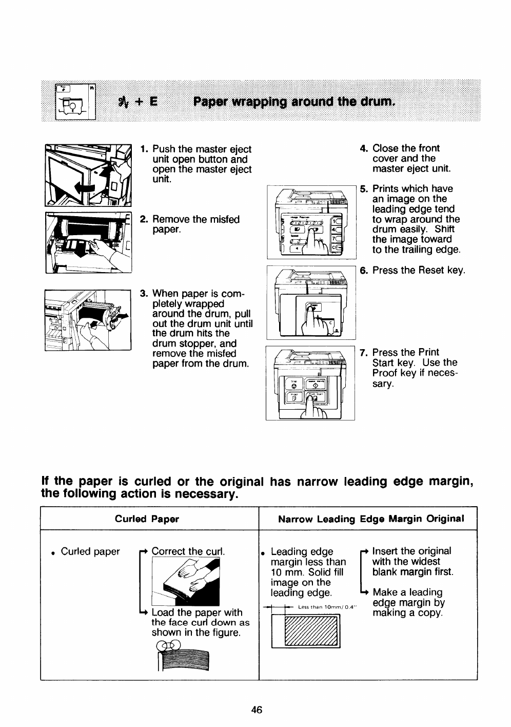
lb.————_I
1.
2.
3.
Push the master eject
unit open button and
open the master eject
unit.
Remove the misfed
paper.
When paper is com-
pletely wrapped
around the drum, pull
out the drum unit until
the drum hits the
drum stopper, and
remove the misfed
paper from the drum.
4.
5.
6
7.
Close the front
cover and the
master eject unit.
Prints which have
an image on the
leading edge tend
to wrap around the
drum easily. Shift
the image toward
to the trailing edge.
Press the Reset key.
Press the Print
Start key. Use the
Proof key if neces-
sary.
If the paper is curled or the Original has narrow leading edge margin,
the following action is necessary.
46
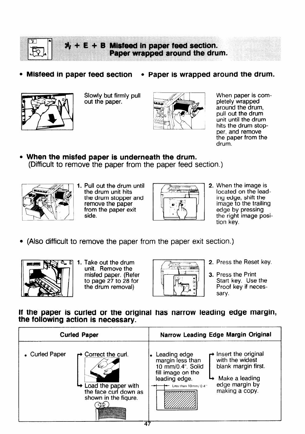
cMisfeed in paper feed section .Paper is wrapped around the drum.
Slowly but firmly pull
out the paper.
.When the misfed ~a~er is underneath the drum.
(Difficult to remov~ th’e paper from the paper feed section.)
When paper is com-
pletely wrapped
around the drum,
pull out the drum
unit until the drum
hits the drum stop-
per, and remove
the paper from the
drum.
_z //%?4 1. Pull out the drum until I~1
the drum stopper and
remove the paper
from the paper exit
side.
Ithe dru-rnUni hits - - I~
●(Also difficult to
m
.,.
P,
v’
$,
,,
,1
2. When the image is
located on the lead-
ing edge, shift the
image to the trailing
edge by pressing
the right image posi-
tion key.
remove the paper from the paper exit section.)
1. Take out the drum
unit. Remove the
misfed paper. (Refer
to page 27 to 28 for
the drum removal)
If the paper is curled or the original
the following action is necessary.
2. Press the Reset key.
1
3. Press the Print
Start key. Use the
Proof key if neces-
sary.
has narrow leading edge margin,
Curled Paper INarrow Leading Edge Margin Original
.Curled Paper Correct the curl.
[a Load the paper with
the face curl down as
shown in the fiqure.
k.-
47
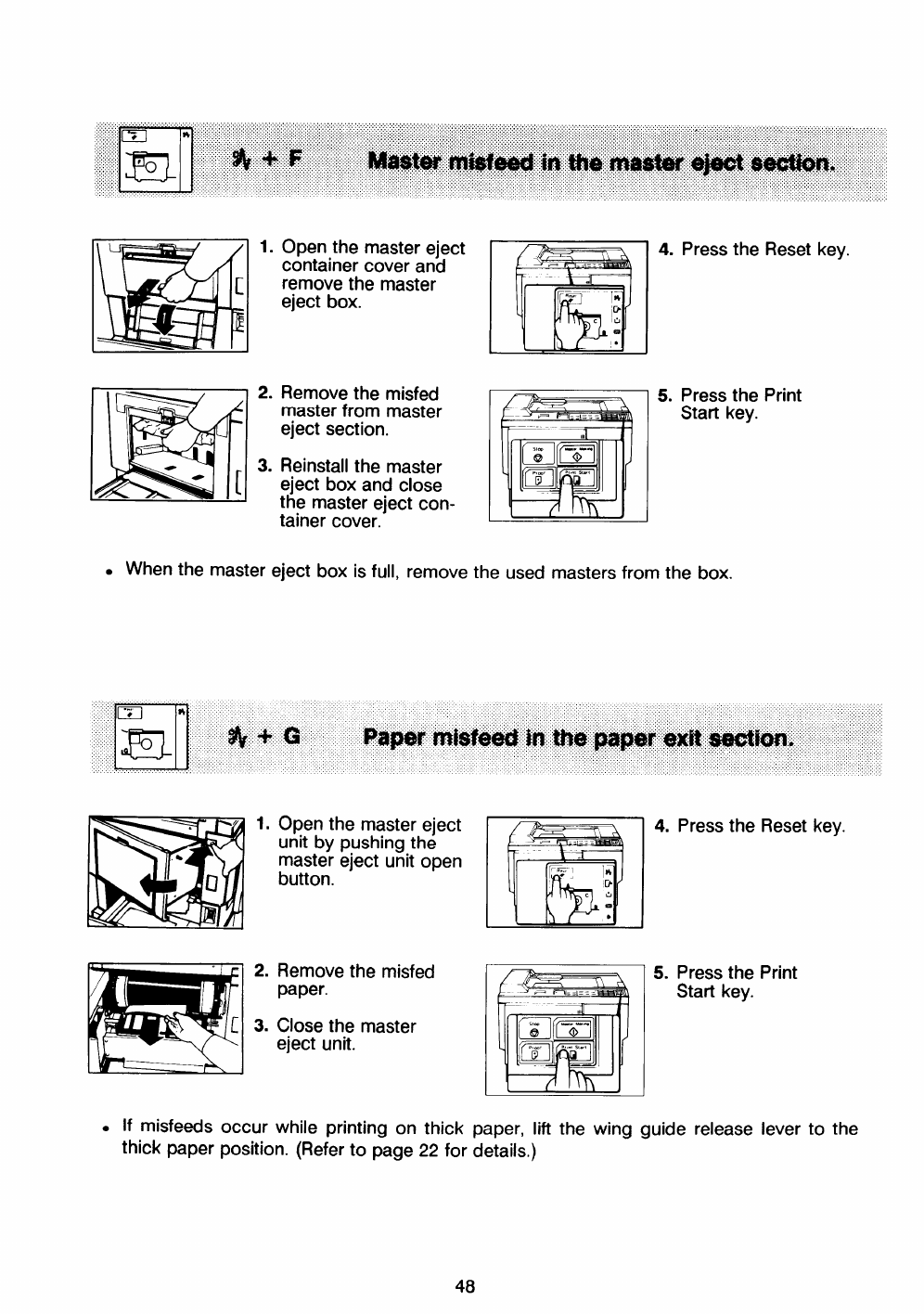
1.
2.
3.
Open the master eject
container cover and
remove the master
eject box.
Remove the misfed
master from master
eject section.
Reinstall the master
eject box and close
the master eject con-
tainer cover.
4. Press the Reset key.
5. Press the Print
Start key.
.When the master eject box is full, remove the used masters from the box.
1.
2.
3.
Open the master eject
unit by pushing the
master eject unit open
button.
Remove the misfed
paper.
Close the master
eject unit.
4. Press the Reset key.
5. Press the Print
~IStart kev.
tII
while printing on thick paper, lift the wing guide release lever to the
.If misfeeds occur
thick paper position. (Refer to page 22 for details.)
48
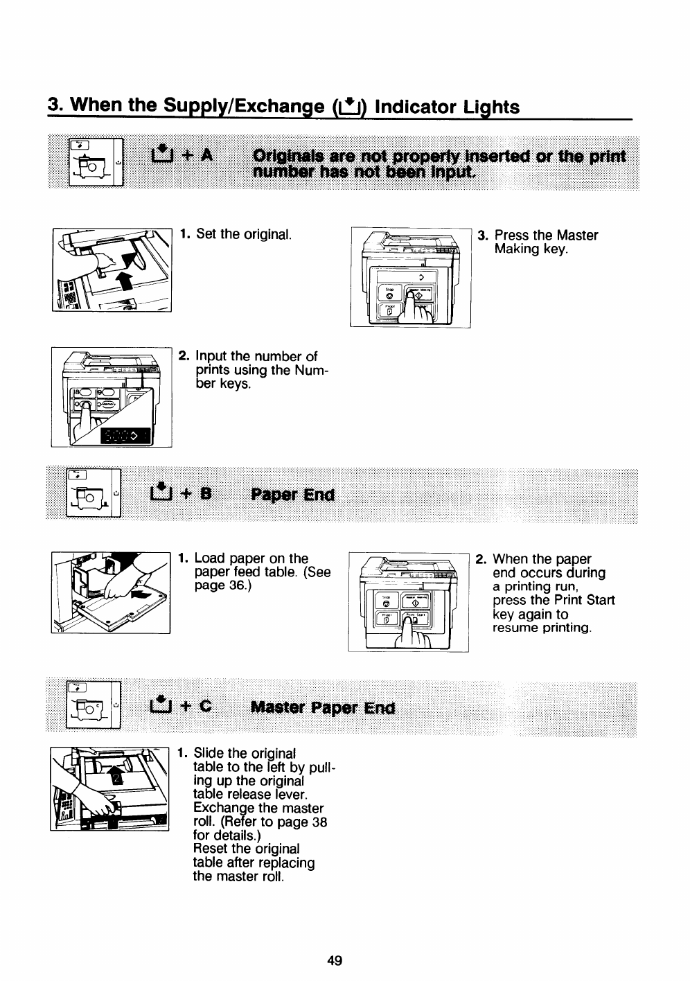
3. When the Supply/Exchange (fi) Indicator Lights
1.
2.
Set the original.
Input the number of
pfints using the Num-
ber keys,
3. Press the Master
Making key.
1. Load paper on the 2.
paper feed table. (See
page 36.)
When the paper
end occurs during
aprinting run,
press the Print Start
key again to
resume printing.
1. Slide the original
table to the left by pull-
ing up the original
table release lever.
Exchange the master
roll. (Refer to page 38
for details.)
Reset the original
table after replacing
the master roll.
49
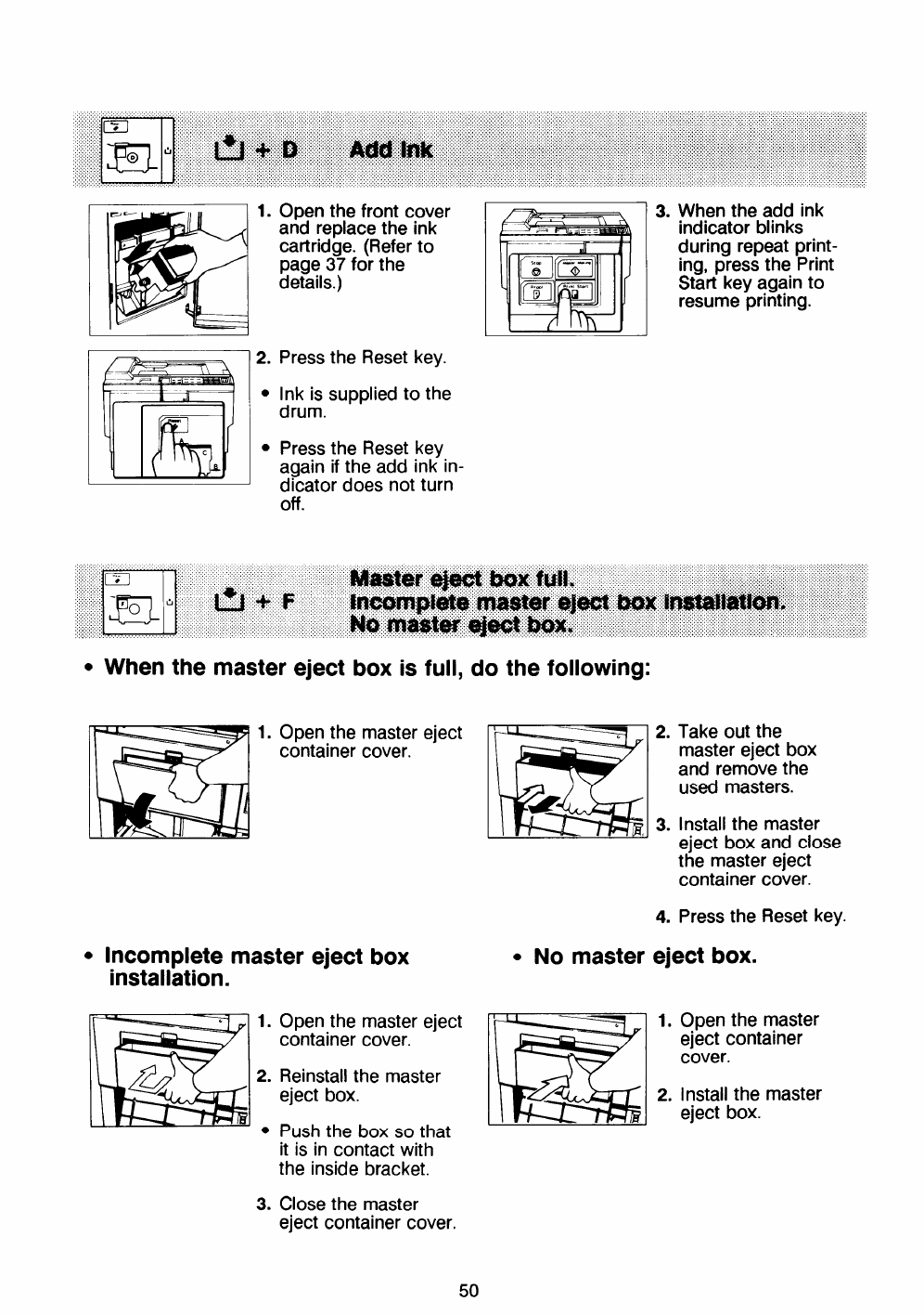
1.
2.
●
●
Open the front cover
and replace the ink
cartridge. (Refer to
page 37 for the
details.)
Press the Reset key.
Ink is supplied to the
drum.
Press the Reset kev
again if the add ink in-
dicator does not turn
off.
3. When the add ink
indicator blinks
during repeat print-
ing, press the Print
Start key again to
resume printing.
.When the master eject box is full, do the following:
1. Open the master eject
container cover.
.Incomplete master eject box
installation.
1.
2.
●
3.
Open the master eject
container cover.
Reinstall the master
eject box.
Push the box so that
it is in contact with
the inside bracket.
Close the master
eject container cover.
●No master
2.
3.
4.
Take out the
master eject box
and remove the
used masters.
Install the master
eject box and close
the master eject
container cover.
Press the Reset key.
eject box.
1.
2.
Open the master
eject container
cover.
install the master
eject box.
50
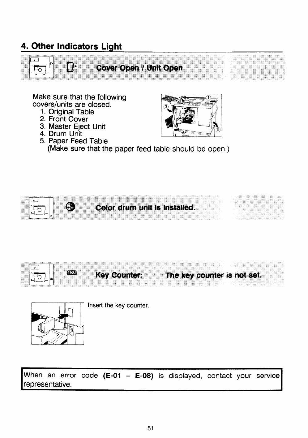
4. Other Indicators Light
Make sure that the following
covers/units are closed.
1. Original Table
2. Front Cover
3. Master Eject Unit
4. Drum Unit
5. Paper Feed Table
(Make sure that the paper feed table should be open
Insert the key counter.
When an error code (E-01 -E-08) is displayed, contact your service
representative.
51
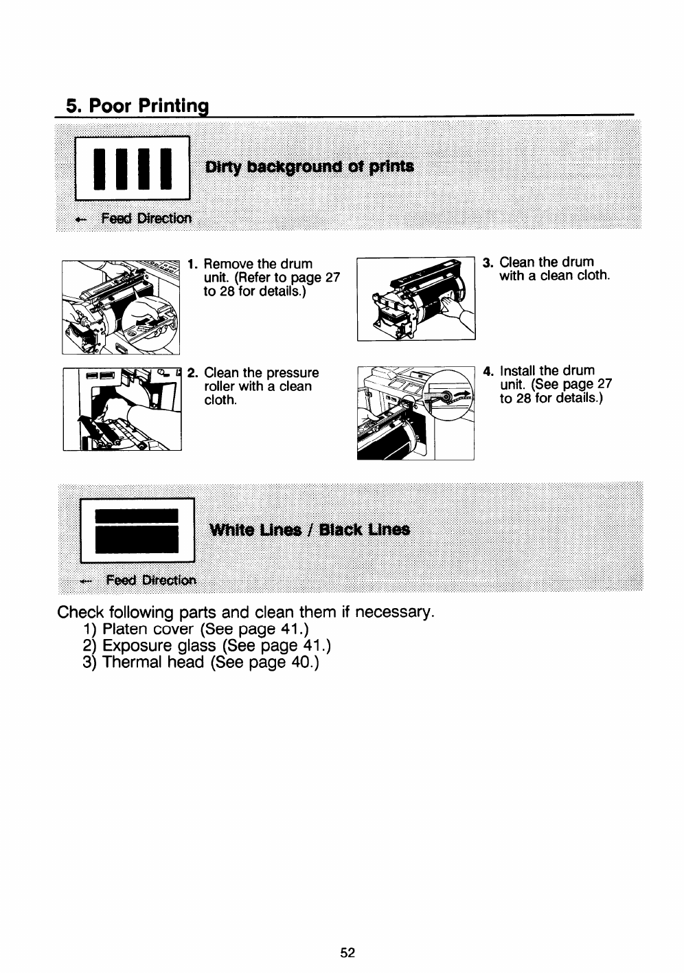
5. Poor Printina
1.
2.
Remove the drum
unit. (Refer to page 27
to 28 for details.)
Clean the pressure
roller with aclean
cloth.
3. Clean the drum
with aclean cloth.
4. Install the drum
unit. (See page 27
to 28 for details.)
Check following parts and clean them if necessary.
1) Platen cover (See page 41.)
2) Exposure glass (See page 41.)
3) Thermal head (See page 40.)
52
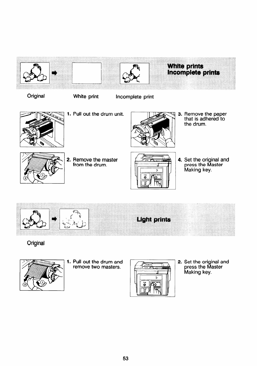
Original White print incomplete print
1. Pull out the drum unit. 3. Remove the paper
that is adhered to
the drum.
2. Remove the master 4.
from the drum. Set the original and
press the Master
Making key.
Original
1. Pull out the drum and
remove two masters. 2. Set the original and
press the Master
Making key.
53
IMISCELLANEOUS I
1. Operating Cautions
1.
2.
3.
4.
5.
6.
7.
8.
9.
If there is no blank area or asolid image area on the leading edge of
the original, create ablank area because the paper may wrap around
the drum or the paper eject pawl may become dirty and cause black
line on prints.
When the paper is curled, stack the paper with the curl face down,
otherwise the paper may wrap around the drum or stains may appear.
Make sure to make afew trial prints to check the image position be-
cause the image position of the trial print
of the original.
If the image registration is not consistent,
than step 3.
may not correspond with that
set the printing speed slower
The leading edge of the prints may become stained if the edge touches
the image of prints on the paper delivery table.
In case of duplex or multicolor printing, leave the printed paper for a
while before the next printing in order to dry the ink on the printed
paper. If this is not done, feed roller marks will appear on the print
image.
If the machine is not used for along period, the image density may
decrease because the ink on the drum may dry. Make extra prints until
the image density recovers.
When the machine is used in IOW temperature conditions, the image
density may decrease. In this case, decrease the printing speed (1 or 2
steps).
The ink of the print on the paper delivery table may stick to the back
side of the next print.
54
10.
11.
12.
13.
14.
15.
16.
When making duplex prints, misdetection of paper wrapping may occur
because the paper delivery sensor detects the black area at the leading
edge of the back side. Keep more than 10mm/O.4° blank area at the
leading edge of the back side of the printing paper.
Do not use the thermal head cleaner for anything but cleaning the ther-
mal head. Also, be Sure to read ttle cautions about the thermal head
cleaner, and be careful as this cleaner is an alcohol.
Take note of the following regarding the cleaner:
●
●
●
●
●
●
Do not take internally.
Do not breathe it.
Keep out of the reach of children.
If it comes in contact with skin, wash well with water.
Keep away from eyes. If it comes in contact with your eyes, wash well. If
irritation occurs, contact your doctor.
Never place it whet’e it will be exposed to heat.
When feeding 51/2’’x8l/2° paper in the sideways direction, the prints may
not stack correctly on the paper delivery table. In this case, push up the
wing guide release lever.
Perform atest print using the Proof key as the first few prints may be
light.
When the machine is mand the power source is less than 90% of the
specified amount, printing quality will decrease. Therefore, make sure
the mains supply is at least 90% of the required amount.
Such paper as postcards do not absorb ink well. Therefore, offset im-
ages may appear on the rear side of following prints. Solid image
originals will make offset image prints.
AS various kinds and qualities of paper exist, Some paper may be
wrapped around the drum and/or cause jams.
55
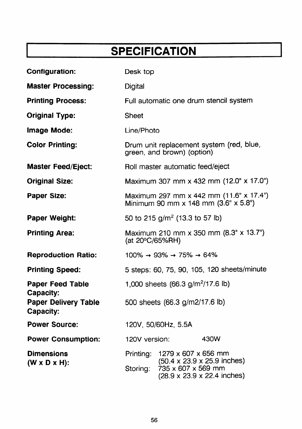
SPECIFICATION 1
Configuration:
Master Processing:
Printing Process:
Original Type:
Image Mode:
Color Printing:
Master Feed/Eject:
Original Size:
Paper Size:
Paper Weight:
Printing Area:
Reproduction Ratio:
Printing Speed:
Paper Feed Table
Capacity:
Paper Delivery Table
Capacity:
Power Source:
Power Consumption:
Dimensions
(W XDXH):
Desk top
Digital
Full automatic one drum stencil system
Sheet
Line/Photo
Drum unit replacement system (red, blue,
green, and brown) (option)
Roll master automatic feed/eject
Maximum 307 mm x432 mm (12.0” x17.0”)
Maximum 297 mm x442 mm (11.6” x17.4”)
Minimum 90 mm x148 mm (3.6” x5.8”)
so to 215 g/m2 (13.3 to 57 lb)
Maximum 210 mm x350 mm (8.3” x13.7”)
(at 20°C/65%RH)
10oyo +935%0-) 75% +64%
5steps: 60, 75, 90, 105, 120 sheets/minute
1,000 sheets (66.3 g/m2/l 7.6 lb)
500 sheets (66.3 g/m2/l 7.6 lb)
120V, 50/60 Hz, 5.5A
120V version: 430W
Printing: 1279 x607 x656 mm
(50.4 x23.9x 25.9 inches)
Storing: 735 x607 x569 mm
(28.9 x23.9x 22.4 inches)
56
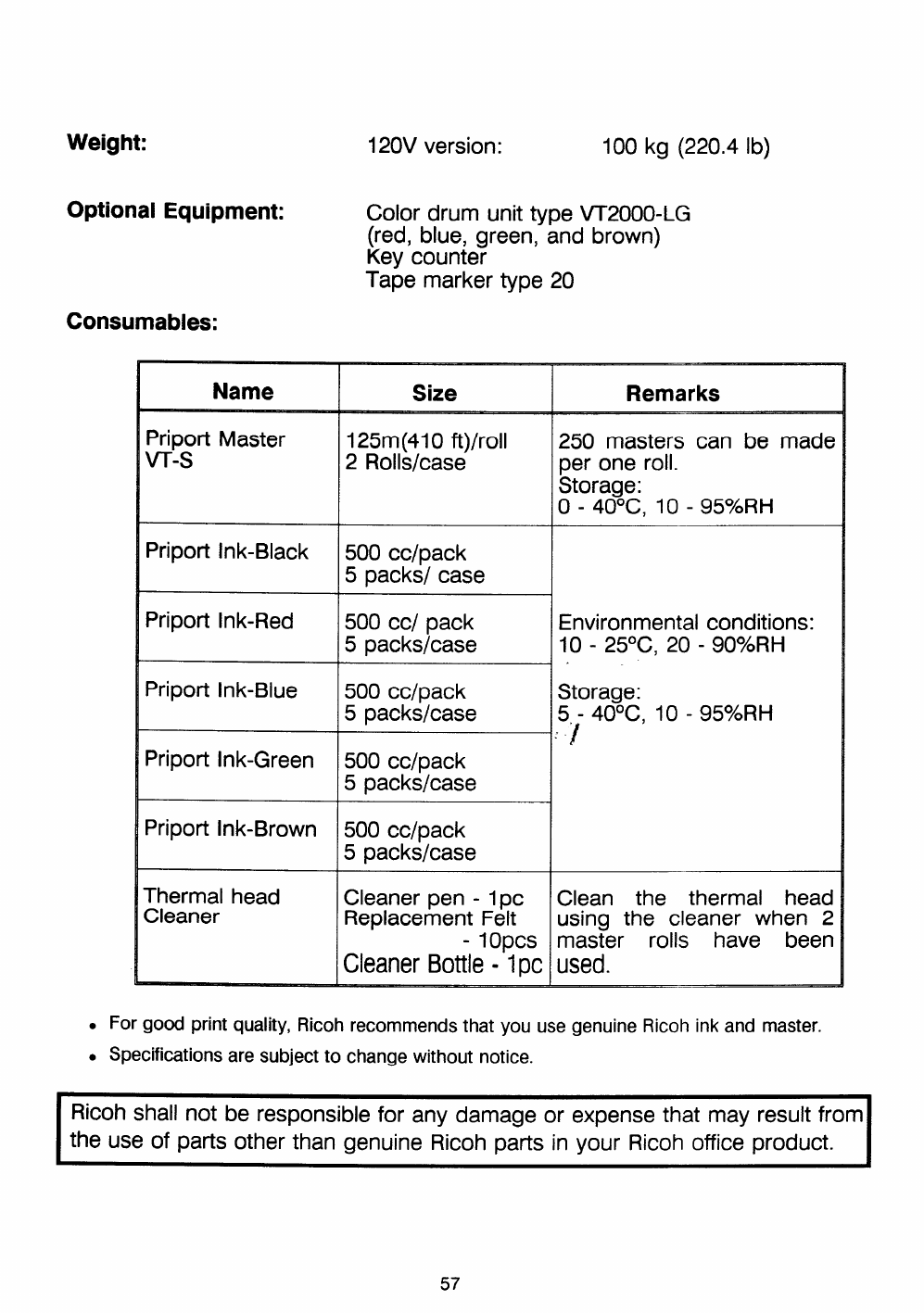
120V version: 100 kg (220.4 lb)
Optional Equipment:
Consumables:
Color drum unit type VT2000-LG
(red, blue, green, and brown)
Key counter
Tape marker type 20
Name Size Remarks
Priport Master 125m(41 Oft)/roll 250 masters can be made
Vr-s 2Rolls/case per one roll.
Storage:
0-40°c, 10- 95$ZORH
Priport Ink-Black 500 cc/pack
5packsl case
Priport Ink-Red 500 cc/ pack Environmental conditions:
5packslcase 10- 25°C, 20- 90YoRH
Priport Ink-Blue 500 cclpack Storage:
5packs/case 5- 40°c, 10- 95YORH
‘1
Priport Ink-Green 500 cc/pack
5packslcase
Priport Ink-Brown 500 cc/pack
5packs/case
Thermal head Cleaner pen -1 pc Clean the thermal head
Cleaner Replacement Felt using the cleaner when 2
-1 Opts master rolls have been
Cleaner Bottle -1 PC used.
For good print quality, Ricoh recommends that you use genuine Ricoh ink and master,
Specifications are subject to change without notice.
Ricoh shall not be responsible for any damage or expense that may result from
the use of parts other than genuine Ricoh parts in your Ricoh office product.
