SAM Electronics NG3050X12-5KW RADARPILOT Platinum User Manual ED3100G130 RP CP
SAM Electronics GmbH RADARPILOT Platinum ED3100G130 RP CP
User Manual

Operating Instructions
NACOS Platinum
Software Version 1.0
RADARPILOT Platinum
RADARPILOT (with transceiver NG 3050 / NG 3051)
CONNINGPILOT
Item No.: ED 3100 G 130 Revision: 03 (2011-08) Order No.:390008509

© SAM Electronics GmbH 2011
The reproduction, distribution, and utilization of this document as well as the
communication of its content to others without explicit authorization is prohibited.
Offenders will be held liable for the payment of damages.
All rights reserved in the event of the grant of a patent, utility model, or design.
Alterations due to technical progress are reserved.
SAM Electronics GmbH
D - 22763 Hamburg
Service
Customer Support Center
Phone: + 49 (0) 18 03 00 85 53
Fax: + 49 (0) 18 03 00 85 54
E-mail: shipservice@sam-electronics.de
The radar transceivers of this NACOS Platinum system are FCC registered as follows:
X-Band 12.5 KW:Q07NG3050X12-5KW
X-Band 25 KW:Q07NG3050X25KW
S-Band 30 KW:Q07NG3051S30KW
For these units the following notes about FCC approval apply:
NOTE:
This equipment has been tested and found to comply with the limits for a Class A digital device, pursuant
to Part 15 of the FCC Rules. These limits are designed to provide reasonable protection against harmful
interference when the equipment is operated in a commercial environment. This equipment generates,
uses, and can radiate radio frequency energy and, if not installed and used in accordance with the
instruction manual, may cause harmful interference to radio communications. Operation of this equip-
ment in a residential area is likely to cause harmful interference in which case the user will be required
to correct the interference at his own expense.
NOTICE:
This device complies with Part 15 of the FCC Rules.
Operation is subject to the following two conditions:
(1)this device may not cause harmful interference, and
(2)this device must accept any interference received, including interference that may cause undesired
operation.
NOTICE:
Changes or modifications made to this equipment not expressly approved by SAM Electronics GmbH in
Hamburg may void the FCC authorization to operate this equipment.
Radiofrequency radiation exposure information:
This equipment complies with FCC radiation exposure limits set forth for an uncontrolled environment.
This equipment should be installed and operated with minimum distance of 21 m between the radiator
and your body (30 KW S-Band Radar). For more details (i.e. X-Band and various antennas and trans-
mitting power) please refer to section A chapter 1.1.2 in this manual.
This transmitter must not be co-located or operating in conjunction with any other antenna or trans-
mitter.

ED 3100 G 140 / 04 (2011-11)
Operating Instructions List of Contents
OI_ANC2010_TOC.fm /10.11.2011 3
NACOS Platinum
List of Contents
I GENERAL . . . . . . . . . . . . . . . . . . . . . . . . . . . . . . . . . . .I - 1
1 About these Operating Instructions . . . . . . . . . . . . . . . . . . . . .I - 3
1.1 Aim and Scope of these Operating Instructions . . . . . . . . . . . . . . . . . . I - 4
1.2 Validity of these Operating Instructions . . . . . . . . . . . . . . . . . . . . . . . . I - 5
1.3 Availability of these Operating Instructions . . . . . . . . . . . . . . . . . . . . . I - 6
1.4 How to Find Information in the Operating Instructions . . . . . . . . . . . . . I - 7
1.4.1 Structure of the Operating Instructions . . . . . . . . . . . . . . . . . . . . . . . . I - 8
1.4.2 How to find Information on Specific Subjects . . . . . . . . . . . . . . . . . . . . I - 9
1.5 Typographical Conventions . . . . . . . . . . . . . . . . . . . . . . . . . . . . . . . I - 10
2 Safety Precautions . . . . . . . . . . . . . . . . . . . . . . . . . . . . . . . .I - 13
2.1 Warnings and Notes in these Operating Instructions . . . . . . . . . . . . . . I - 14
2.2 Meaning of Safety Signs . . . . . . . . . . . . . . . . . . . . . . . . . . . . . . . . . . I - 15
2.3 General Safety Notes – NACOS Platinum . . . . . . . . . . . . . . . . . . . . . . I - 17
2.4 Authorisation and Qualification of Personnel . . . . . . . . . . . . . . . . . . . I - 18
2.5 Commissioning . . . . . . . . . . . . . . . . . . . . . . . . . . . . . . . . . . . . . . . . I - 19
2.6 Obligatory Safety Inspection . . . . . . . . . . . . . . . . . . . . . . . . . . . . . . I - 20
3 NACOS Platinum System Description . . . . . . . . . . . . . . . . . . .I - 21
3.1 What is the NACOS Platinum? . . . . . . . . . . . . . . . . . . . . . . . . . . . . . I - 22
3.2 Customisation . . . . . . . . . . . . . . . . . . . . . . . . . . . . . . . . . . . . . . . . . I - 23
3.3 Applicable Standards . . . . . . . . . . . . . . . . . . . . . . . . . . . . . . . . . . . . I - 25
4 Multi Function Display . . . . . . . . . . . . . . . . . . . . . . . . . . . . . I - 27
4.1 General System Description MFD . . . . . . . . . . . . . . . . . . . . . . . . . . . I - 28
4.2 Operating Devices . . . . . . . . . . . . . . . . . . . . . . . . . . . . . . . . . . . . . . I - 29
4.2.1 Pointing Devices – Trackball and Mouse . . . . . . . . . . . . . . . . . . . . . . I - 30
4.2.2 Keyboard . . . . . . . . . . . . . . . . . . . . . . . . . . . . . . . . . . . . . . . . . . . . I - 32
4.2.3 The ASCII Keyboard . . . . . . . . . . . . . . . . . . . . . . . . . . . . . . . . . . . . I - 33
4.2.4 The RADAR Keyboard . . . . . . . . . . . . . . . . . . . . . . . . . . . . . . . . . . . I - 34
4.2.5 The TRACKPILOT Keyboard . . . . . . . . . . . . . . . . . . . . . . . . . . . . . . . I - 35
4.3 TFT Monitor . . . . . . . . . . . . . . . . . . . . . . . . . . . . . . . . . . . . . . . . . . I - 36
4.3.1 Nominal Viewing Distance . . . . . . . . . . . . . . . . . . . . . . . . . . . . . . . . I - 37
4.3.2 Colour Distortions on Monitors with Flat Screens (TFT Monitors) . . . . . I - 38
4.3.3 Printers . . . . . . . . . . . . . . . . . . . . . . . . . . . . . . . . . . . . . . . . . . . . . I - 39
4.4 Startup and Shutdown of MFDs . . . . . . . . . . . . . . . . . . . . . . . . . . . . I - 40
4.5 Basic Settings . . . . . . . . . . . . . . . . . . . . . . . . . . . . . . . . . . . . . . . . . I - 41
4.5.1 Adjusting the Display . . . . . . . . . . . . . . . . . . . . . . . . . . . . . . . . . . . . I - 42
4.5.2 Setting Date and Time . . . . . . . . . . . . . . . . . . . . . . . . . . . . . . . . . . . I - 43
5 NACOS Platinum Graphical User Interface . . . . . . . . . . . . . . .I - 45
5.1 Super Home . . . . . . . . . . . . . . . . . . . . . . . . . . . . . . . . . . . . . . . . . . I - 46
5.2 Screen Layout . . . . . . . . . . . . . . . . . . . . . . . . . . . . . . . . . . . . . . . . . I - 47

NACOS Platinum
ED 3100 G 140 / 04 (2011-11)
Operating Instructions
List of Contents
OI_ANC2010_TOC.fm /10.11.2011
4
5.2.1 Title Bar . . . . . . . . . . . . . . . . . . . . . . . . . . . . . . . . . . . . . . . . . . . . . .I - 48
5.2.1.1 Brilliance . . . . . . . . . . . . . . . . . . . . . . . . . . . . . . . . . . . . . . . . . . . . .I - 48
5.2.1.2 Active Application Title . . . . . . . . . . . . . . . . . . . . . . . . . . . . . . . . . . .I - 49
5.2.1.3 Date and Time . . . . . . . . . . . . . . . . . . . . . . . . . . . . . . . . . . . . . . . . .I - 49
5.2.1.4 Alive Indication . . . . . . . . . . . . . . . . . . . . . . . . . . . . . . . . . . . . . . . . .I - 49
5.3 Sidebar . . . . . . . . . . . . . . . . . . . . . . . . . . . . . . . . . . . . . . . . . . . . . .I - 51
5.3.1 Permanent Area . . . . . . . . . . . . . . . . . . . . . . . . . . . . . . . . . . . . . . . .I - 52
5.3.2 Non-Permanent Area . . . . . . . . . . . . . . . . . . . . . . . . . . . . . . . . . . . . .I - 54
5.3.3 Menu Bar . . . . . . . . . . . . . . . . . . . . . . . . . . . . . . . . . . . . . . . . . . . . .I - 56
5.3.3.1 Full Screen Mode . . . . . . . . . . . . . . . . . . . . . . . . . . . . . . . . . . . . . . .I - 58
5.4 Application Area . . . . . . . . . . . . . . . . . . . . . . . . . . . . . . . . . . . . . . . .I - 59
5.4.1 Application Area Frames . . . . . . . . . . . . . . . . . . . . . . . . . . . . . . . . . .I - 60
5.5 Tabbed Panels . . . . . . . . . . . . . . . . . . . . . . . . . . . . . . . . . . . . . . . . .I - 62
5.6 Lists & Tables . . . . . . . . . . . . . . . . . . . . . . . . . . . . . . . . . . . . . . . . . .I - 64
5.7 Dialogues . . . . . . . . . . . . . . . . . . . . . . . . . . . . . . . . . . . . . . . . . . . . .I - 66
5.7.1 Popup Edit Windows . . . . . . . . . . . . . . . . . . . . . . . . . . . . . . . . . . . . .I - 67
5.8 Tooltips . . . . . . . . . . . . . . . . . . . . . . . . . . . . . . . . . . . . . . . . . . . . . .I - 68
5.9 Controls – Adjusting Values . . . . . . . . . . . . . . . . . . . . . . . . . . . . . . . .I - 69
5.9.1 Fields . . . . . . . . . . . . . . . . . . . . . . . . . . . . . . . . . . . . . . . . . . . . . . . .I - 70
5.9.2 Field Groups . . . . . . . . . . . . . . . . . . . . . . . . . . . . . . . . . . . . . . . . . . .I - 71
5.9.3 Sliders . . . . . . . . . . . . . . . . . . . . . . . . . . . . . . . . . . . . . . . . . . . . . . .I - 72
5.9.4 Push Buttons . . . . . . . . . . . . . . . . . . . . . . . . . . . . . . . . . . . . . . . . . .I - 73
5.9.5 Dropdown Menus . . . . . . . . . . . . . . . . . . . . . . . . . . . . . . . . . . . . . . .I - 74
5.9.6 Check Boxes . . . . . . . . . . . . . . . . . . . . . . . . . . . . . . . . . . . . . . . . . . .I - 75
5.9.7 Scroll Bars . . . . . . . . . . . . . . . . . . . . . . . . . . . . . . . . . . . . . . . . . . . .I - 76
5.9.8 Spin boxes . . . . . . . . . . . . . . . . . . . . . . . . . . . . . . . . . . . . . . . . . . . .I - 77
5.9.9 Keys for Numeric Values . . . . . . . . . . . . . . . . . . . . . . . . . . . . . . . . . .I - 78
5.9.10 Zoom and Pan Control . . . . . . . . . . . . . . . . . . . . . . . . . . . . . . . . . . . .I - 79
5.9.11 Alphanumeric and Graphical Indications . . . . . . . . . . . . . . . . . . . . . . .I - 80
5.9.12 Alarm Icons . . . . . . . . . . . . . . . . . . . . . . . . . . . . . . . . . . . . . . . . . . .I - 81
5.10 Mouse Pointers and Clicks . . . . . . . . . . . . . . . . . . . . . . . . . . . . . . . . .I - 82
5.10.1 Pointers in RADAR and ECDIS . . . . . . . . . . . . . . . . . . . . . . . . . . . . . .I - 83
5.10.2 Mouse Pointers for Machinery . . . . . . . . . . . . . . . . . . . . . . . . . . . . . . .I - 84
II QUICK START GUIDE. . . . . . . . . . . . . . . . . . . . . . . . . .II - 1
1 How to start quickly . . . . . . . . . . . . . . . . . . . . . . . . . . . . . . II - 3
1.1 The S-Mode for RADAR . . . . . . . . . . . . . . . . . . . . . . . . . . . . . . . . . . .II - 4
1.2 The S-Mode for ECDIS . . . . . . . . . . . . . . . . . . . . . . . . . . . . . . . . . . . .II - 5
III MAIN APPLICATIONS . . . . . . . . . . . . . . . . . . . . . . . . . III - 1
1 Overview of Products and Applications . . . . . . . . . . . . . . . . . III - 3
1.1 NACOS Platinum Products . . . . . . . . . . . . . . . . . . . . . . . . . . . . . . . . III - 4
1.2 RADAR Application . . . . . . . . . . . . . . . . . . . . . . . . . . . . . . . . . . . . . III - 5
1.3 ECDIS Application . . . . . . . . . . . . . . . . . . . . . . . . . . . . . . . . . . . . . . III - 7

ED 3100 G 140 / 04 (2011-11)
Operating Instructions List of Contents
OI_ANC2010_TOC.fm /10.11.2011 5
NACOS Platinum
1.4 CONNING Application . . . . . . . . . . . . . . . . . . . . . . . . . . . . . . . . . . . III - 8
1.5 TRACKPILOT Application . . . . . . . . . . . . . . . . . . . . . . . . . . . . . . . . . III - 9
1.6 MACHINERY Application . . . . . . . . . . . . . . . . . . . . . . . . . . . . . . . . . III - 10
1.7 Common Functions for Products and Applications . . . . . . . . . . . . . . . III - 11
2 Common Functions for Navigation . . . . . . . . . . . . . . . . . . . .III - 15
2.1 The Consistent Common Reference System (CCRS) . . . . . . . . . . . . . III - 16
2.2 Context Menus . . . . . . . . . . . . . . . . . . . . . . . . . . . . . . . . . . . . . . . III - 18
2.3 The Chart Information Window . . . . . . . . . . . . . . . . . . . . . . . . . . . . III - 21
3 Permanent Area for Navigation . . . . . . . . . . . . . . . . . . . . . .III - 23
3.1 Display . . . . . . . . . . . . . . . . . . . . . . . . . . . . . . . . . . . . . . . . . . . . . III - 24
3.1.1 Orientation . . . . . . . . . . . . . . . . . . . . . . . . . . . . . . . . . . . . . . . . . . III - 25
3.1.2 Range . . . . . . . . . . . . . . . . . . . . . . . . . . . . . . . . . . . . . . . . . . . . . III - 26
3.1.3 Rings . . . . . . . . . . . . . . . . . . . . . . . . . . . . . . . . . . . . . . . . . . . . . . III - 27
3.1.4 CCRP . . . . . . . . . . . . . . . . . . . . . . . . . . . . . . . . . . . . . . . . . . . . . . III - 28
3.1.5 Screen Stabilisation . . . . . . . . . . . . . . . . . . . . . . . . . . . . . . . . . . . . III - 29
3.2 Navigation Sensors . . . . . . . . . . . . . . . . . . . . . . . . . . . . . . . . . . . . III - 33
3.2.1 Integrity Marking of Sensors . . . . . . . . . . . . . . . . . . . . . . . . . . . . . III - 34
3.2.2 Heading and Speed . . . . . . . . . . . . . . . . . . . . . . . . . . . . . . . . . . . . III - 35
3.2.3 Position . . . . . . . . . . . . . . . . . . . . . . . . . . . . . . . . . . . . . . . . . . . . III - 42
3.3 Vector and Trails . . . . . . . . . . . . . . . . . . . . . . . . . . . . . . . . . . . . . . III - 49
3.3.1 Ground / Water Stabilisation . . . . . . . . . . . . . . . . . . . . . . . . . . . . . III - 50
3.3.2 Vector . . . . . . . . . . . . . . . . . . . . . . . . . . . . . . . . . . . . . . . . . . . . . III - 51
3.3.3 Trails . . . . . . . . . . . . . . . . . . . . . . . . . . . . . . . . . . . . . . . . . . . . . . III - 52
3.3.4 Plot . . . . . . . . . . . . . . . . . . . . . . . . . . . . . . . . . . . . . . . . . . . . . . . III - 53
3.3.5 Predict . . . . . . . . . . . . . . . . . . . . . . . . . . . . . . . . . . . . . . . . . . . . . III - 54
3.4 Charts . . . . . . . . . . . . . . . . . . . . . . . . . . . . . . . . . . . . . . . . . . . . . III - 55
3.4.1 The Chart Status Line . . . . . . . . . . . . . . . . . . . . . . . . . . . . . . . . . . III - 56
3.5 Targets . . . . . . . . . . . . . . . . . . . . . . . . . . . . . . . . . . . . . . . . . . . . III - 58
3.5.1 Fusion . . . . . . . . . . . . . . . . . . . . . . . . . . . . . . . . . . . . . . . . . . . . . III - 59
3.5.2 Sleeping Targets . . . . . . . . . . . . . . . . . . . . . . . . . . . . . . . . . . . . . . III - 60
A RADAR. . . . . . . . . . . . . . . . . . . . . . . . . . . . . . . . . . . . A - 1
1 General Information . . . . . . . . . . . . . . . . . . . . . . . . . . . . . . . A - 3
1.1 RADAR Safety . . . . . . . . . . . . . . . . . . . . . . . . . . . . . . . . . . . . . . . . . . A - 4
1.1.1 RADAR Safety – Electrical Systems . . . . . . . . . . . . . . . . . . . . . . . . . . . A - 4
1.1.2 RADAR Safety – Radiation . . . . . . . . . . . . . . . . . . . . . . . . . . . . . . . . . A - 5
1.1.3 RADAR Safety – Mechanical Systems . . . . . . . . . . . . . . . . . . . . . . . . . . A - 6
1.2 Current IHO Standards / Regulatory Approvals . . . . . . . . . . . . . . . . . . . A - 7
1.3 System Structure and Installation . . . . . . . . . . . . . . . . . . . . . . . . . . . . A - 8
1.4 Basics / Evaluation of the RADAR Video . . . . . . . . . . . . . . . . . . . . . . . A - 11
1.4.1 Basics of the Evaluation of RADAR Video in Platinum Series . . . . . . . . A - 11
1.4.2 Achievable RADAR Range . . . . . . . . . . . . . . . . . . . . . . . . . . . . . . . . . A - 14
1.4.3 Distortions of the RADAR Video . . . . . . . . . . . . . . . . . . . . . . . . . . . . A - 15
1.4.4 Undesirable Echo Displays and Effects . . . . . . . . . . . . . . . . . . . . . . . . A - 16

NACOS Platinum
ED 3100 G 140 / 04 (2011-11)
Operating Instructions
List of Contents
OI_ANC2010_TOC.fm /10.11.2011
6
1.4.5 RADAR Setting for the Display of Racon Codes . . . . . . . . . . . . . . . . . . A - 20
1.4.6 RADAR Settings for Target Enhancer Detection . . . . . . . . . . . . . . . . . A - 20
1.4.7 RADAR Setting for SART Detection (X-Band only) . . . . . . . . . . . . . . . . A - 21
1.4.8 Transmission formats . . . . . . . . . . . . . . . . . . . . . . . . . . . . . . . . . . . A - 23
1.5 Basic setting of the RADAR Video . . . . . . . . . . . . . . . . . . . . . . . . . . . A - 24
1.6 RADAR Accuracy . . . . . . . . . . . . . . . . . . . . . . . . . . . . . . . . . . . . . . . A - 27
2 The RADAR Keyboard . . . . . . . . . . . . . . . . . . . . . . . . . . . . .A - 29
3 An Overview of the Screen . . . . . . . . . . . . . . . . . . . . . . . . . .A - 31
4 RADAR Application Area . . . . . . . . . . . . . . . . . . . . . . . . . . .A - 33
4.1 The Zoom and Pan Control . . . . . . . . . . . . . . . . . . . . . . . . . . . . . . . A - 34
5 RADAR Sidebar - Permanent Area . . . . . . . . . . . . . . . . . . . . .A - 37
5.1 RADAR Transceiver Settings . . . . . . . . . . . . . . . . . . . . . . . . . . . . . . . A - 38
5.1.1 Transceiver Selection . . . . . . . . . . . . . . . . . . . . . . . . . . . . . . . . . . . . A - 38
5.1.2 Master / Slave Selection . . . . . . . . . . . . . . . . . . . . . . . . . . . . . . . . . . A - 39
5.1.3 Pulse Length . . . . . . . . . . . . . . . . . . . . . . . . . . . . . . . . . . . . . . . . . . A - 40
5.1.4 Adjusting the Transceiver . . . . . . . . . . . . . . . . . . . . . . . . . . . . . . . . A - 40
5.2 RADAR Video Settings . . . . . . . . . . . . . . . . . . . . . . . . . . . . . . . . . . . A - 42
5.2.1 Gain . . . . . . . . . . . . . . . . . . . . . . . . . . . . . . . . . . . . . . . . . . . . . . . A - 42
5.2.2 Sea . . . . . . . . . . . . . . . . . . . . . . . . . . . . . . . . . . . . . . . . . . . . . . . . A - 42
5.2.3 Rain . . . . . . . . . . . . . . . . . . . . . . . . . . . . . . . . . . . . . . . . . . . . . . . . A - 43
5.2.4 Enhance . . . . . . . . . . . . . . . . . . . . . . . . . . . . . . . . . . . . . . . . . . . . . A - 43
5.2.5 Video Emphasis . . . . . . . . . . . . . . . . . . . . . . . . . . . . . . . . . . . . . . . A - 44
5.2.6 Hide Video / Overlay . . . . . . . . . . . . . . . . . . . . . . . . . . . . . . . . . . . . A - 44
5.3 Toolset1 and 2 . . . . . . . . . . . . . . . . . . . . . . . . . . . . . . . . . . . . . . . . A - 46
5.3.1 EBL . . . . . . . . . . . . . . . . . . . . . . . . . . . . . . . . . . . . . . . . . . . . . . . . A - 46
5.3.2 VRM . . . . . . . . . . . . . . . . . . . . . . . . . . . . . . . . . . . . . . . . . . . . . . . A - 48
5.3.3 Operating VRM and EBL jointly . . . . . . . . . . . . . . . . . . . . . . . . . . . . . A - 49
5.4 Parallel Index Lines (PI) . . . . . . . . . . . . . . . . . . . . . . . . . . . . . . . . . . A - 50
6 RADAR Sidebar - Non-Permanent Area . . . . . . . . . . . . . . . . .A - 53
7 Target Handling . . . . . . . . . . . . . . . . . . . . . . . . . . . . . . . . .A - 55
7.1 Overview . . . . . . . . . . . . . . . . . . . . . . . . . . . . . . . . . . . . . . . . . . . . A - 56
7.2 Manual Target Acquisition . . . . . . . . . . . . . . . . . . . . . . . . . . . . . . . . A - 59
7.3 Manual Target Selection . . . . . . . . . . . . . . . . . . . . . . . . . . . . . . . . . A - 60
7.4 Automatic Target Acquisition . . . . . . . . . . . . . . . . . . . . . . . . . . . . . . A - 61
7.5 Settings for Dangerous Targets . . . . . . . . . . . . . . . . . . . . . . . . . . . . A - 62
7.6 Settings for Acquisition/Guard Zones . . . . . . . . . . . . . . . . . . . . . . . . . A - 64
7.7 Target Fusion . . . . . . . . . . . . . . . . . . . . . . . . . . . . . . . . . . . . . . . . . A - 65
7.8 Deletion and Loss of Targets . . . . . . . . . . . . . . . . . . . . . . . . . . . . . . A - 66
7.9 Critical Target . . . . . . . . . . . . . . . . . . . . . . . . . . . . . . . . . . . . . . . . . A - 67
7.10 Target List . . . . . . . . . . . . . . . . . . . . . . . . . . . . . . . . . . . . . . . . . . . A - 68
7.11 Target Display . . . . . . . . . . . . . . . . . . . . . . . . . . . . . . . . . . . . . . . . A - 70
7.12 Trial Manoeuvre . . . . . . . . . . . . . . . . . . . . . . . . . . . . . . . . . . . . . . . A - 72

ED 3100 G 140 / 04 (2011-11)
Operating Instructions List of Contents
OI_ANC2010_TOC.fm /10.11.2011 7
NACOS Platinum
7.13 Reference Target Tracking . . . . . . . . . . . . . . . . . . . . . . . . . . . . . . . . A - 78
7.14 ARPA Training . . . . . . . . . . . . . . . . . . . . . . . . . . . . . . . . . . . . . . . . . A - 79
7.15 ARPA Malfunctions . . . . . . . . . . . . . . . . . . . . . . . . . . . . . . . . . . . . . A - 81
7.16 AIS Malfunctions . . . . . . . . . . . . . . . . . . . . . . . . . . . . . . . . . . . . . . . A - 82
8 User Symbols . . . . . . . . . . . . . . . . . . . . . . . . . . . . . . . . . . A - 83
8.1 Symbols . . . . . . . . . . . . . . . . . . . . . . . . . . . . . . . . . . . . . . . . . . . . . A - 84
8.2 Areas . . . . . . . . . . . . . . . . . . . . . . . . . . . . . . . . . . . . . . . . . . . . . . . A - 88
8.3 Lines . . . . . . . . . . . . . . . . . . . . . . . . . . . . . . . . . . . . . . . . . . . . . . . A - 90
8.4 Events and Text . . . . . . . . . . . . . . . . . . . . . . . . . . . . . . . . . . . . . . . A - 92
9 CHARTRADAR (optional) . . . . . . . . . . . . . . . . . . . . . . . . . . A - 93
9.1 Overview . . . . . . . . . . . . . . . . . . . . . . . . . . . . . . . . . . . . . . . . . . . . A - 94
9.2 Basic Adjustments . . . . . . . . . . . . . . . . . . . . . . . . . . . . . . . . . . . . . . A - 95
9.2.1 Temporary Hiding the Chart Background . . . . . . . . . . . . . . . . . . . . . . A - 95
9.2.2 Selection of Charts . . . . . . . . . . . . . . . . . . . . . . . . . . . . . . . . . . . . . A - 95
9.2.3 Matching the Chart with the RADAR Presentation . . . . . . . . . . . . . . . . A - 95
9.2.4 References Used . . . . . . . . . . . . . . . . . . . . . . . . . . . . . . . . . . . . . . . A - 95
9.2.5 Range Scale and Modes . . . . . . . . . . . . . . . . . . . . . . . . . . . . . . . . . . A - 96
9.3 Selecting the Objects to be Displayed in the Vector Chart . . . . . . . . . . A - 97
9.3.1 Overview . . . . . . . . . . . . . . . . . . . . . . . . . . . . . . . . . . . . . . . . . . . . A - 97
9.3.2 Categories of Display Groups . . . . . . . . . . . . . . . . . . . . . . . . . . . . . . A - 97
9.3.3 Select a Category . . . . . . . . . . . . . . . . . . . . . . . . . . . . . . . . . . . . . . A - 98
9.3.4 Select the Primary Chart Information Set (PCIS) . . . . . . . . . . . . . . . . A - 98
9.3.5 Indication of Category in the Status Line . . . . . . . . . . . . . . . . . . . . . . A - 99
9.3.6 Defining the Symbol Presentation . . . . . . . . . . . . . . . . . . . . . . . . . . A - 100
9.3.7 Setting the Display of Text Labels . . . . . . . . . . . . . . . . . . . . . . . . . . A - 100
9.3.8 Switch on Additional Information . . . . . . . . . . . . . . . . . . . . . . . . . . A - 100
9.3.9 Switch on Conditionally Displayed Features . . . . . . . . . . . . . . . . . . . A - 101
9.4 CHARTRADAR Application Area . . . . . . . . . . . . . . . . . . . . . . . . . . . . A - 102
9.5 Application Area Context Menu . . . . . . . . . . . . . . . . . . . . . . . . . . . . A - 103
9.6 Setting the Depths Lines to be Displayed in the Vector Chart . . . . . . . A - 104
9.7 Setting the Own Ship’s Draft . . . . . . . . . . . . . . . . . . . . . . . . . . . . . A - 106
9.8 Activating the Chart Monitoring . . . . . . . . . . . . . . . . . . . . . . . . . . . A - 107
9.9 Setting the Look-Ahead Sector . . . . . . . . . . . . . . . . . . . . . . . . . . . . A - 108
9.10 Chart Maintenance . . . . . . . . . . . . . . . . . . . . . . . . . . . . . . . . . . . . A - 109
9.11 Main Differences between CHARTRADAR and Full ECDISPILOT . . . . . A - 110
C VOYAGE PLANNING AND MONITORING . . . . . . . . . . . . C - 1
1 Voyage Planning . . . . . . . . . . . . . . . . . . . . . . . . . . . . . . . . . C - 3
1.1 Generation of Routes . . . . . . . . . . . . . . . . . . . . . . . . . . . . . . . . . . . . . C - 4
1.1.1 General Information about Pre-planned Tracks . . . . . . . . . . . . . . . . . . C - 5
1.1.2 Generation, Handling and Administration of the Routes . . . . . . . . . . . . . C - 7
1.1.3 Route Display Settings . . . . . . . . . . . . . . . . . . . . . . . . . . . . . . . . . . . . C - 9
1.1.4 Route Editing - Graphical . . . . . . . . . . . . . . . . . . . . . . . . . . . . . . . . . C - 10
1.1.5 Route Editing - Text Mode . . . . . . . . . . . . . . . . . . . . . . . . . . . . . . . . C - 16

NACOS Platinum
ED 3100 G 140 / 04 (2011-11)
Operating Instructions
List of Contents
OI_ANC2010_TOC.fm /10.11.2011
8
1.1.6 Details of the Waypoint Data . . . . . . . . . . . . . . . . . . . . . . . . . . . .C - 22
1.1.7 Checking of Routes . . . . . . . . . . . . . . . . . . . . . . . . . . . . . . . . . . . . . C - 25
1.1.7.1 Geometrical Check . . . . . . . . . . . . . . . . . . . . . . . . . . . . . . . . . . . . . C - 26
1.1.7.2 Check against the Electronic Chart and the User made Chart Objects . . C - 29
1.1.7.3 Computation of Sailing Times . . . . . . . . . . . . . . . . . . . . . . . . . . . . . . C - 31
1.1.8 Completing the Generation of the Route . . . . . . . . . . . . . . . . . . . . . . C - 33
1.1.9 Import / Export Routes . . . . . . . . . . . . . . . . . . . . . . . . . . . . . . . . . . C - 34
2 Chart and Route Monitoring . . . . . . . . . . . . . . . . . . . . . . . . .C - 35
2.1 Route Monitoring: Own Ship against the System Route . . . . . . . . . . . . C - 37
2.2 Chart Monitoring: Own Ship against Vector - / User Chart Objects . . . . C - 38
2.2.1 Monitoring on the Basis of a Vector Chart . . . . . . . . . . . . . . . . . . . . . C - 40
2.2.2 Monitoring against User Symbols . . . . . . . . . . . . . . . . . . . . . . . . . . . C - 42
D CONNING . . . . . . . . . . . . . . . . . . . . . . . . . . . . . . . . . .D - 1
1 Operating the Conning . . . . . . . . . . . . . . . . . . . . . . . . . . . . .D - 3
1.1 General . . . . . . . . . . . . . . . . . . . . . . . . . . . . . . . . . . . . . . . . . . . . . . D - 4
1.2 An Overview of the Screen . . . . . . . . . . . . . . . . . . . . . . . . . . . . . . . . . D - 5
1.3 Conning Display - Navigation . . . . . . . . . . . . . . . . . . . . . . . . . . . . . . . D - 7
1.4 Docking Display . . . . . . . . . . . . . . . . . . . . . . . . . . . . . . . . . . . . . . . . D - 8
1.5 Conning Home Waypoint List . . . . . . . . . . . . . . . . . . . . . . . . . . . . . . . D - 9
1.6 Conning Display - Machinery . . . . . . . . . . . . . . . . . . . . . . . . . . . . . . D - 10
1.6.1 The Rate of Turn Indication . . . . . . . . . . . . . . . . . . . . . . . . . . . . . . . D - 11
1.7 Conning Sidebar - Permanent Area . . . . . . . . . . . . . . . . . . . . . . . . . . D - 12
1.8 Conning Sidebar - Non-permanent Area . . . . . . . . . . . . . . . . . . . . . . D - 13
1.9 The Alarm List on Conning . . . . . . . . . . . . . . . . . . . . . . . . . . . . . . . . D - 14
1.9.1 Wind and Current . . . . . . . . . . . . . . . . . . . . . . . . . . . . . . . . . . . . . . D - 15
1.9.2 Depth . . . . . . . . . . . . . . . . . . . . . . . . . . . . . . . . . . . . . . . . . . . . . . D - 16
1.9.3 Autopilot Performance . . . . . . . . . . . . . . . . . . . . . . . . . . . . . . . . . . . D - 17
F SENSORS . . . . . . . . . . . . . . . . . . . . . . . . . . . . . . . . . . F - 1
1 AIS . . . . . . . . . . . . . . . . . . . . . . . . . . . . . . . . . . . . . . . . . . .F - 3
1.1 AIS Summarized Briefly . . . . . . . . . . . . . . . . . . . . . . . . . . . . . . . . . . . F - 4
1.2 Overview of Functions and Operating Procedures . . . . . . . . . . . . . . . . . F - 5
1.3 Setting the Voyage Data . . . . . . . . . . . . . . . . . . . . . . . . . . . . . . . . . . F - 6
1.4 Setting the transmitter / Transmitter Status . . . . . . . . . . . . . . . . . . . . . F - 8
1.5 Channel Management . . . . . . . . . . . . . . . . . . . . . . . . . . . . . . . . . . . F - 10
1.6 Receiving AIS Messages . . . . . . . . . . . . . . . . . . . . . . . . . . . . . . . . . F - 13
IV OPTIONAL APPLICATIONS . . . . . . . . . . . . . . . . . . . . . IV - 1
H MAINTENANCE . . . . . . . . . . . . . . . . . . . . . . . . . . . . . .H - 1

ED 3100 G 140 / 04 (2011-11)
Operating Instructions List of Contents
OI_ANC2010_TOC.fm /10.11.2011 9
NACOS Platinum
1 Performance Monitor . . . . . . . . . . . . . . . . . . . . . . . . . . . . . . H - 3
2 Data Maintenance of the Electronic Charts . . . . . . . . . . . . . . . H - 5
2.1 General . . . . . . . . . . . . . . . . . . . . . . . . . . . . . . . . . . . . . . . . . . . . . . H - 5
2.2 Starting Chart Maintenance . . . . . . . . . . . . . . . . . . . . . . . . . . . . . . . . H - 6
2.3 Chart Maintenance Application Area . . . . . . . . . . . . . . . . . . . . . . . . . . H - 7
2.4 Update of Charts from Media . . . . . . . . . . . . . . . . . . . . . . . . . . . . . . . H - 8
2.5 Messages during Chart Update . . . . . . . . . . . . . . . . . . . . . . . . . . . . . . H - 9
2.6 Display Charts which are on a Media or a MFD (workstation) . . . . . . . . H - 10
2.7 Maintenance of Charts on your MFD (workstation) . . . . . . . . . . . . . . . H - 11
2.8 Display Expander . . . . . . . . . . . . . . . . . . . . . . . . . . . . . . . . . . . . . . H - 12
2.9 Backup/Restore of Map Data . . . . . . . . . . . . . . . . . . . . . . . . . . . . . . H - 13
3 Manual ENC Update Editor . . . . . . . . . . . . . . . . . . . . . . . . . H - 15
4 Hardware Maintenance . . . . . . . . . . . . . . . . . . . . . . . . . . . . H - 18
4.1 Periodical Checks . . . . . . . . . . . . . . . . . . . . . . . . . . . . . . . . . . . . . . H - 18
4.1.1 Limited-Lifetime Devices . . . . . . . . . . . . . . . . . . . . . . . . . . . . . . . . . H - 18
4.2 Check of the Colour Reproduction . . . . . . . . . . . . . . . . . . . . . . . . . . . H - 18
5 SW Version and Updates . . . . . . . . . . . . . . . . . . . . . . . . . . H - 19
5.1 SW Version . . . . . . . . . . . . . . . . . . . . . . . . . . . . . . . . . . . . . . . . . . . H - 19
5.2 SW Updates . . . . . . . . . . . . . . . . . . . . . . . . . . . . . . . . . . . . . . . . . . H - 19
V ALARMS. . . . . . . . . . . . . . . . . . . . . . . . . . . . . . . . . . . V - 1
1 General Information . . . . . . . . . . . . . . . . . . . . . . . . . . . . . . . V - 3
1.1 Colour code for the alarm indications: . . . . . . . . . . . . . . . . . . . . . . . . . V - 4
1.2 Overview of the alarm window . . . . . . . . . . . . . . . . . . . . . . . . . . . . . . V - 6
1.2.1 Example of an alarm . . . . . . . . . . . . . . . . . . . . . . . . . . . . . . . . . . . . . V - 7
2 Alarm Management . . . . . . . . . . . . . . . . . . . . . . . . . . . . . . . V - 9
2.1 Behaviour when an Alarm comes up . . . . . . . . . . . . . . . . . . . . . . . . . V - 10
2.2 List of Alarms . . . . . . . . . . . . . . . . . . . . . . . . . . . . . . . . . . . . . . . . . V - 11
2.2.1 Navigation Sensor Alarms . . . . . . . . . . . . . . . . . . . . . . . . . . . . . . . . V - 12
2.2.2 RADAR Alarms . . . . . . . . . . . . . . . . . . . . . . . . . . . . . . . . . . . . . . . . V - 17
2.2.3 AIS Alarms . . . . . . . . . . . . . . . . . . . . . . . . . . . . . . . . . . . . . . . . . . . V - 19
2.2.4 ECDIS Alarms . . . . . . . . . . . . . . . . . . . . . . . . . . . . . . . . . . . . . . . . V - 22
2.2.5 Trackpilot Alarms . . . . . . . . . . . . . . . . . . . . . . . . . . . . . . . . . . . . . . V - 23
2.2.6 Trackpilot Alarm Signal Outputs . . . . . . . . . . . . . . . . . . . . . . . . . . . . V - 32
2.2.7 VDR Alarms . . . . . . . . . . . . . . . . . . . . . . . . . . . . . . . . . . . . . . . . . . V - 34
2.2.8 Machinery Alarms . . . . . . . . . . . . . . . . . . . . . . . . . . . . . . . . . . . . . . V - 35
VI LISTS AND INDEXES . . . . . . . . . . . . . . . . . . . . . . . . . .VI - 1
VII DOCUMENT HISTORY . . . . . . . . . . . . . . . . . . . . . . . . VII - 1


GENERAL


ED 3100 G 140 / 04 (2011-11)
Operating Instructions
I-1 About these Operating Instructions
I General.fm / 10.11.11 I-3
NACOS Platinum
1 About these Operating Instructions
In this chapter, you will find general information about these operating instructions which have been
delivered with your NACOS Platinum. It informs you about:
-
I-Aim and Scope of these Operating Instructions
on page I-4
-
I-Validity of these Operating Instructions
on page I-5
-
I-How to Find Information in the Operating Instructions
on page I-7
-
I-Typographical Conventions
on page I-10
☞ jjjjtut
Do not forget to read the chapter on general safety measures. This is obligatory
to read! See chapter I - 2 on page 13.

NACOS Platinum
ED 3100 G 140 / 04 (2011-11)
Operating Instructions
I-1 About these Operating Instructions
I General.fm / 10.11.11
I-4
1.1 Aim and Scope of these Operating Instructions
These operating instructions describe how the NACOS Platinum and its software applications work, and
how to operate the applications.
Since the operating instructions are generic, i.e. generally applicable to the ship control system NACOS
Platinum, some information and functions or features described may not be used in your specific instal-
lation. This depends on the customisation of your system. See chapter 3.2 on page I-23. For exact and
specific features of your particular installation, please refer to the relevant order and delivery documents.
The NACOS Platinum must only be operated by persons who have passed the
relevant mandatory training on the respective systems and applications. Only
reading these operating instructions cannot replace such training.

ED 3100 G 140 / 04 (2011-11)
Operating Instructions
I-1 About these Operating Instructions
I General.fm / 10.11.11 I-5
NACOS Platinum
1.2 Validity of these Operating Instructions
These instructions are valid for the NACOS Platinum and its applications. Specific safety regulations for
components used in or in combination with the system are not affected by these instructions.

NACOS Platinum
ED 3100 G 140 / 04 (2011-11)
Operating Instructions
I-1 About these Operating Instructions
I General.fm / 10.11.11
I-6
1.3 Availability of these Operating Instructions
Have these operating instructions always at hand on location. If appl., ensure that copies are available
at all relevant operator panels, MFDs and Outstations. You can also access an online version of the oper-
ating instructions directly in the NACOS Platinum system. See chapter "Menu Bar" on page I-56.

ED 3100 G 140 / 04 (2011-11)
Operating Instructions
I-1 About these Operating Instructions
I General.fm / 10.11.11 I-7
NACOS Platinum
1.4 How to Find Information in the Operating Instructions

NACOS Platinum
ED 3100 G 140 / 04 (2011-11)
Operating Instructions
I-1 About these Operating Instructions
I General.fm / 10.11.11
I-8
1.4.1 Structure of the Operating Instructions
When reading through or skimming through the overall operating instructions, it is always a good idea
to go from general to more specific subjects, i.e. to start with this general part of the operating instruc-
tions and then continue with the part describing the application you wish to learn about. Again, in the
descriptions of the applications, read the introductory chapters before getting into detail. Otherwise you
might miss information which are assumed to be understood in the chapters describing specific details.
The NACOS Platinum Operating Instructions are divided into different parts. The main parts are
numbered using roman numbers. The sections of the main applications like RADAR and ECDIS and
optional applications like Autopilot are labelled using capital latin letters, the sub-sections inside these
sections are numbered using arabic numbers. The documentation of an application can be handled as a
separate document and therefore can also be ordered separately. The structure of the NACOS Platinum
Operating Instructions is as follows:
-
I-GENERAL
This is the part you are currently reading. It provides general information which are important in
order to be able to understand the other parts of the operating instructions.
-
II-QUICK START GUIDE
Essential information on the individual applications giving a quick overview of important functions.
- Common Functions
- Operating in the Permanant Area
- Navigation Sensors and Instruments
-
III-MAIN APPLICATIONS
and
IV-OPTIONAL APPLICATIONS
Descriptions of the main applications and optional applications:
- Common functions
- Operating in the Permanent Area
- Navigation Sensors and
- RADAR
- ECDIS
- ...
- Autopilot (optional)
- ...
-
V-ALARMS
Information regarding NACOS Platinum system alarms.
-
F-SENSORS
Descriptions on the sensoring equipment installed aboard.
-
H-MAINTENANCE
Instructions regarding cleaning, preventive maintenance, regular maintenance.
-
VI-LISTS AND INDEXES
Standard key word index, list of figures

ED 3100 G 140 / 04 (2011-11)
Operating Instructions
I-1 About these Operating Instructions
I General.fm / 10.11.11 I-9
NACOS Platinum
1.4.2 How to find Information on Specific Subjects
There will also be the case that you are basically familiar with the NACOS Platinum but only need punc-
tual information on one specific topic or detail. In order to find information on such specific subjects, you
can use the
- List of Contents
- Index of key words
Here, you can look up specific key words. You will also find, e.g. the names of functions, controls,
and keys like [ESC] or [DUTY] at the beginning of the index.
-
II-QUICK START GUIDE
Here you will find essential information on the individual applications which will give you a quick
overview of important functions.
- List of Abbreviations
When describing a system like the NACOS Platinum, it is necessary to use terms and expressions
which may be unfamiliar to you in the beginning. Most of the technical terms will be explained to
you as you read your way through the more general chapters, or when reading the chapters on the
specific applications. However, as a general source of information we have provided a list of abbre-
viations. See
VI-LISTS AND INDEXES
.

NACOS Platinum
ED 3100 G 140 / 04 (2011-11)
Operating Instructions
I-1 About these Operating Instructions
I General.fm / 10.11.11
I-10
1.5 Typographical Conventions
The typographical conventions used in the operating instructions are kept simple, but still it is essential
that you are sure to understand their meaning before reading the instructions. The following special signs
are used for specific purposes:
[ ] (square brackets),
< > (triangular brackets),
{ } (curly brackets),
These signs are used as shown in the following examples:

ED 3100 G 140 / 04 (2011-11)
Operating Instructions
I-1 About these Operating Instructions
I General.fm / 10.11.11 I-11
NACOS Platinum
Expression Explanation
[KEY NAME] This convention is used to refer to an operator key on either a panel keypad
(Machinery application), a key on a console’s keyboard, on a computer
keyboard, or on the onscreen keyboard.
The text is the same text as on the respective key. The text can be letters,
digits or signs. Note that the text inside the brackets is written in capital
letters.
Example:
Press [ALARM LIST] to view the Alarm List.
This means that you must press the key with the text "ALARM LIST" written
on it, in order to view the Alarm List.
[KEY] + [2nd KEY] This convention is used to refer to a key combination on the onscreen
keyboard or on a computer keyboard. Example:
Press [ALT]+[F4] to close the window.
This means that you must press and hold the [ALT] key, and while holding the
[ALT] key you have to press [F4].
[ ] [ ] [ ] [ ] The symbols in the square brackets refer to the respective arrow keys on
operator panels (Machinery application).
[ ] [ ] [ ] [ ] The symbols in the square brackets refer to the respective arrow keys on a
console’s keyboard, on a computer keyboard, or on the onscreen keyboard.
Abcd List Heading capitalisation and bold typeface are used when directly referring to
names of NACOS Platinum functions and UI elements such as menus, opera-
tional modes, reports, lists, etc.
The text can be in more than one word.
Examples:
Select Color & in the main menu.
From any mode you can call up the Alarm List by pressing the [ALARM LIST]
key on the panel.
Main > Submenu
> Sub-Submenu This is an abbreviated way for:
Click on Main, then on Submenu and afterwards on Sub-Submenu
☞ This symbol indicates a hint.
<variable> Describes a text string of variable length and contents.
The text inside the brackets is not the actual text, but a reference to a text
which is individual to your specific system.
The length of the text is not specified by the text inside the brackets.
The expression can refer to both text and numbers.
Example:
The display will show <duty engineer>.
This means that the display will show the name of the selected duty engineer,
e.g. "3RD ENGINEER".

NACOS Platinum
ED 3100 G 140 / 04 (2011-11)
Operating Instructions
I-1 About these Operating Instructions
I General.fm / 10.11.11
I-12
Table I / 1 Typographical conventions in these operating instructions
{nnn} Describes a number with a fixed number of digits which is input or output.
The number of letters inside the brackets describes the number of digits. The
number must not include any decimal point.
Example:
Enter a channel number in the format {nnn}.
This means that you must enter the number of a unit as a three digit number,
without any decimal point.
NOTE:
You have to use zeros (0) to fill the empty spaces, if the number is less than
100 (e.g. 056)
{nnn.} Like {nnn}, but there may be a decimal point at any place in the number, or
none.
Example
The value is displayed in the format {nnnn.}.
In the example the value may be, e.g. "12.35" or "450.6" or "0045". When
entering such values, the decimal point will sometimes be preset by the
system.
DD-MMM-YYYY The date in international format which is used in the system.
Example:
21 AUG 2009
for the 21st of August 2009.
HH:MM:SS The time format used in the system. The 24 hour format is used.
Examples:
06:30:00
stands for half past six and 0 seconds in the morning
(6:30 am) and
23:58:00
is two minutes to midnight.
Expression Explanation

ED 3100 G 140 / 04 (2011-11)
Operating Instructions
I-2 Safety Precautions
I General.fm / 10.11.11 I-13
NACOS Platinum
2 Safety Precautions
This chapter describes general safety measures to be taken into account when working with or on the
NACOS Platinum. In the chapters describing the applications of the NACOS Platinum you will find further
important safety notes and warnings which are specific to the applications.
NACOS Platinum
ED 3100 G 140 / 04 (2011-11)
Operating Instructions
I-2 Safety Precautions
I General.fm / 10.11.11
I-14
2.1 Warnings and Notes in these Operating Instructions
The warning levels and styles differ slightly from the suggestions of the ANSI Z.535 standard. We delib-
erately decided to use a three-level system of warnings in these operating instructions which is a mix of
ANSI and ISO standards, and which is very explicit and comprehensible. The different warning levels
have the following meaning:
☞ Notes & Hints: This symbol indicates useful notes and hints which will ease understanding the
system or speed up operation.
This sign is used whenever severe injuries or even death
will
occur as conse-
quence of un-awareness or disregard of the described safety rules.
This sign is used whenever severe injuries or even death
may
occur as conse-
quence of un-awareness or disregard of the described safety rules.
This sign is used when special care must be taken to prevent unexpected conse-
quences such as damage to equipment, incorrect or incalculable operation and
behaviour of equipment.
ED 3100 G 140 / 04 (2011-11)
Operating Instructions
I-2 Safety Precautions
I General.fm / 10.11.11 I-15
NACOS Platinum
2.2 Meaning of Safety Signs
The operating instructions use the following safety signs which you will also find on equipment. Their
meaning is described shortly in order to give you an idea of the importance and the specific aspects to
be aware of.
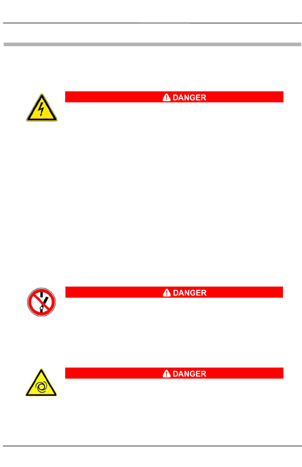
HIGH VOLTAGE!
In case that the equipment is in use, dangerous voltages are present. Touching
live parts of devices energised with these voltages will result severe injuries or
even death. Appropriate actions must be taken. Before starting to work, observe
the following safety rules:
1. Switch off the equipment, disconnect the equipment from the mains
supply.
2. Take precautions against inadvertent re-connection.
3. To verify that circuits are dead and no voltage is present perform the
appropriate measurements.
4. Ground and short-circuit.
5. Cover live parts in the proximity or otherwise protect them against
touching.
The dangerous voltages are no longer present.
Voltage may only be applied to components being worked on when this is
expressly prescribed (e.g. during troubleshooting). Mains switches are live even
when the equipment is switched off. During work always observe the relevant
regulations for the prevention of accidents, e.g. German VBG 4, or EN 292. Only
use suitable, intact tools and measuring instruments!
DANGER! WORK IN PROGRESS! DO NOT SWITCH!
The switch(es) marked with this sign must never be operated.
Severe injuries or even death can occur as consequence of disregard.
The sign will have amendments like the name of the person who has marked the
switch(es) and time/date of mounting of the sign.
Only the person stated on the sign may remove the sign and operate the
switch(es).
TURNING DEVICES!
Marked devices or devices in the vicinity of this sign may start turning automati-
cally if the equipment is in use. Always switch off the respective equipment or
drives of the devices. Take precautions to prevent inadvertent reactivation of the
devices before you start to work on the devices.
NACOS Platinum
ED 3100 G 140 / 04 (2011-11)
Operating Instructions
I-2 Safety Precautions
I General.fm / 10.11.11
I-16
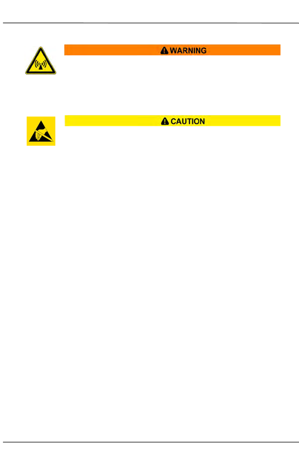
NACOS Platinum components contain electrostatic sensitive devices. Observe precautions for handling.
The discharge of electrostatic energy into a semiconductor can destroy the semiconductor or change its
properties. Before a respective unit’s housing is opened to remove or touch a board, the service equip-
ment, Order No. 586-5011, must be used:
1. The mat must be positioned at the workplace.
2. The added potential equalization cable must be connected to the snap fastener and the clamp to a
suitable protective earth contact. The cable contains a 1 MW resistor which must not be removed.
3. The wrist band must be put on. When the spiral cable is connected to the snap fastener, the
discharge line is established.
4. Thoroughly grounded soldering, measurement and test tools must be used. If these tools are
supplied with power from the 230 VAC mains, this supply must be protected by a fault current plug,
stock No. 593-8099.
Boards and units that contain ESD-sensitive semiconductors are marked with the symbol shown above.
All assisting persons who might come into contact with the endangered ESD-sensitive boards must also
use the ESD equipment.
WARNING! ELECTROMAGNETIC RADIATION!
Marked devices or devices in the vicinity of this sign may emit electromagnetic
radiation that can cause injury. Always switch off the respective equipment. take
precautions to prevent inadvertent reactivation before you start to work on the
devices. Observe the radiation danger zone of radar antennas. See table A / 1.
ELECTROSTATIC SENSITIVE DEVICES!
Devices marked with this sign are extremely sensitive with regards to electrostatic
discharge (ESD). They may be handled only by qualified personnel who must take
the appropriate actions to avoid discharges.

ED 3100 G 140 / 04 (2011-11)
Operating Instructions
I-2 Safety Precautions
I General.fm / 10.11.11 I-17
NACOS Platinum
2.3 General Safety Notes – NACOS Platinum
As a very general rule, keep your workplace clean and tidy, it helps preventing accidents! Ensure unob-
structed access to all workstations, operator panels, controls, and relevant switchgear cabinets in order
to enable instant response to alarms!
You are obliged to read these operating instructions prior to operation and to
adhere to the operating instructions in operation in order to prevent possible
danger and to ensure compliance with the designated use of the equipment.
Prevention of danger includes that operator personnel are trained and authorised
for safe operation of the equipment. We assume no liability for damage due to
improper operation which could have been prevented.
NOTE:
Further potential danger when working with and on the NACOS Platinum is
described in the respective sections on these processes.
NACOS Platinum
ED 3100 G 140 / 04 (2011-11)
Operating Instructions
I-2 Safety Precautions
I General.fm / 10.11.11
I-18
2.4 Authorisation and Qualification of Personnel
Persons authorised to operate the system are specially instructed and trained operating personnel of the
user. Persons authorised to carry out cleaning, maintenance, and troubleshooting are the specially
trained and skilled personnel of the user as well as SAM Electronics personnel being qualified by training,
knowledge and experience. Persons operating or servicing the NACOS Platinum must be familiar with the
general safety regulations and specific safety systems and they must have passed all required training
and must have read the relevant operating instructions and manuals before starting work.
Only authorised persons may operate the NACOS Platinum.
Danger for persons, things and the environment in case of improper operation or
maintenance and repair of the NACOS Platinum.
Only authorised persons are permitted to carry out cleaning and maintenance
work, or troubleshooting on the NACOS Platinum!

ED 3100 G 140 / 04 (2011-11)
Operating Instructions
I-2 Safety Precautions
I General.fm / 10.11.11 I-19
NACOS Platinum
2.5 Commissioning
DANGER! WORK IN PROGRESS! DO NOT SWITCH!
It is not permissible to connect the ship’s mains to the system before setting-to-
work by a qualified and authorised person. The mains must be switched off (e.g.
by means of a common isolating switch or a circuit breaker) in the ship’s supply
or the mains cable must be disconnected until commissioning is carried out.

NACOS Platinum
ED 3100 G 140 / 04 (2011-11)
Operating Instructions
I-2 Safety Precautions
I General.fm / 10.11.11
I-20
2.6 Obligatory Safety Inspection
Inspect and survey the safety systems at intervals prescribed by the responsible classification society or
other relevant authorities.

ED 3100 G 140 / 04 (2011-11)
Operating Instructions
I-3 NACOS Platinum System Description
I General.fm / 10.11.11 I-21
NACOS Platinum
3 NACOS Platinum System Description
NACOS Platinum
ED 3100 G 140 / 04 (2011-11)
Operating Instructions
I-3 NACOS Platinum System Description
I General.fm / 10.11.11
I-22
3.1 What is the NACOS Platinum?
The NACOS Platinum is the state-of-the-art integrated Navigation-Automation-Control-System from
SAM Electronics. It consists of separate applications which form the desired specific system installed on
a ship. In an installation, the set of applications may range from a stand-alone RADAR installation to a
full-featured comprehensive installation.
The NACOS Platinum design is the result of the efforts of a multidisciplinary usability team consisting of
specialists from SAM Electronics, Chalmers University (Gothenburg, Sweden) and TNO Human Factors
(Soesterberg, The Netherlands). In addition to high quality and reliability of the cost-effective solution,
the main focus of the NACOS Platinum is on usability, modularity and scalability, ease of installation,
commissioning and servicing, as well as integration with third-party systems.
NACOS Platinum products serve a large variety of possible installations in a professional shipborne envi-
ronment ranging from stand-alone RADAR installations meeting the minimum requirements aboard up to
complex installations on a large ship including RADAR, ECDIS, Route Planning, Conning, Machinery and
various other applications to navigate the ship safely, and reliably to monitor and control the processes
aboard.
The applications of the NACOS Platinum are operated using standardised workstations. The workstations
will be called Multi Functional Display (MFD) further on. See chapter I - 4 on page 27. MFDs are the
standardised operating consoles used as MMI to the NACOS Platinum. They are based on PCs running
under Windows 7. From a MFD, you will have access to the applications installed in your NACOS Platinum
so that the workplaces aboard are standardised. All applications can be made available at any MFD. See
chapter I - 3.2 on page 23.
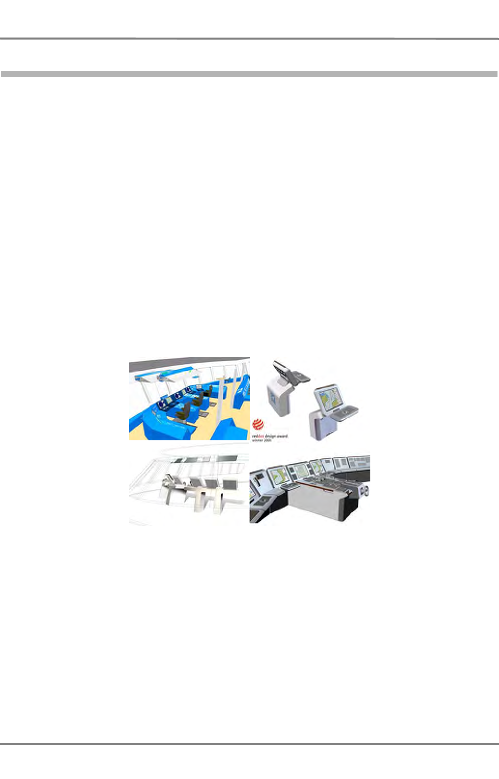
Fig. I / 1 MFD console design
The full suite of NACOS Platinum applications and possibly integrated third-party products provide the
user with the required information and control functions and thus essentially support the user in
performing the assigned tasks both in everyday routines and in difficult situations or in case of problems.
The vast amount of information resulting from the ship's operation is always presented in a well-struc-
tured and concise manner so that users will have a clear overview of the ship's situation at all times.
ED 3100 G 140 / 04 (2011-11)
Operating Instructions
I-3 NACOS Platinum System Description
I General.fm / 10.11.11 I-23
NACOS Platinum
3.2 Customisation
Your NACOS Platinum has been customised by SAM Electronics according to the ship-specific require-
ments which were specified when the system was ordered. In this context, customising means installing
the required hardware and setting up the configuration of the hardware according to the ship-specific
requirements.
Customisation covers the selection of available applications to meet your specific requirements but also
involves adaptations regarding the individual applications. For example, the number of operator panels
used in the Machinery application can be individually configured. This is done using special system tools
which are used by SAM Electronics engineers and technicians only, and documented in the delivery docu-
ments.
Hence, in these operating instructions, the words "customisation" and "configuration" refer to the
customisation provided by SAM Electronics, unless specific NACOS Platinum functions such as, e.g., the
printer configuration are dealt with. For exact and specific features and functional scope of your particular
installation, please refer to the relevant order and delivery documents.
NACOS Platinum products serve a large variety of possible installations in a professional shipborne envi-
ronment ranging from stand-alone RADAR installations meeting the minimum requirements aboard to
complex installations on a large ship including RADAR, ECDIS, Route Planning, Conning, Machinery (Auto-
mation) and various other applications to navigate the ship safely, and to monitor and control the proc-
esses aboard.
Installation, customisation, configuration, as well as initial startup are carried out by SAM Electronics
according to the order specifications upon delivery of the NACOS Platinum. Thus, this is not covered by
these operating instructions. The actual installation aboard a ship is always specifically customised to the
individual needs. The scalability of the NACOS Platinum enables individual systems across the entire
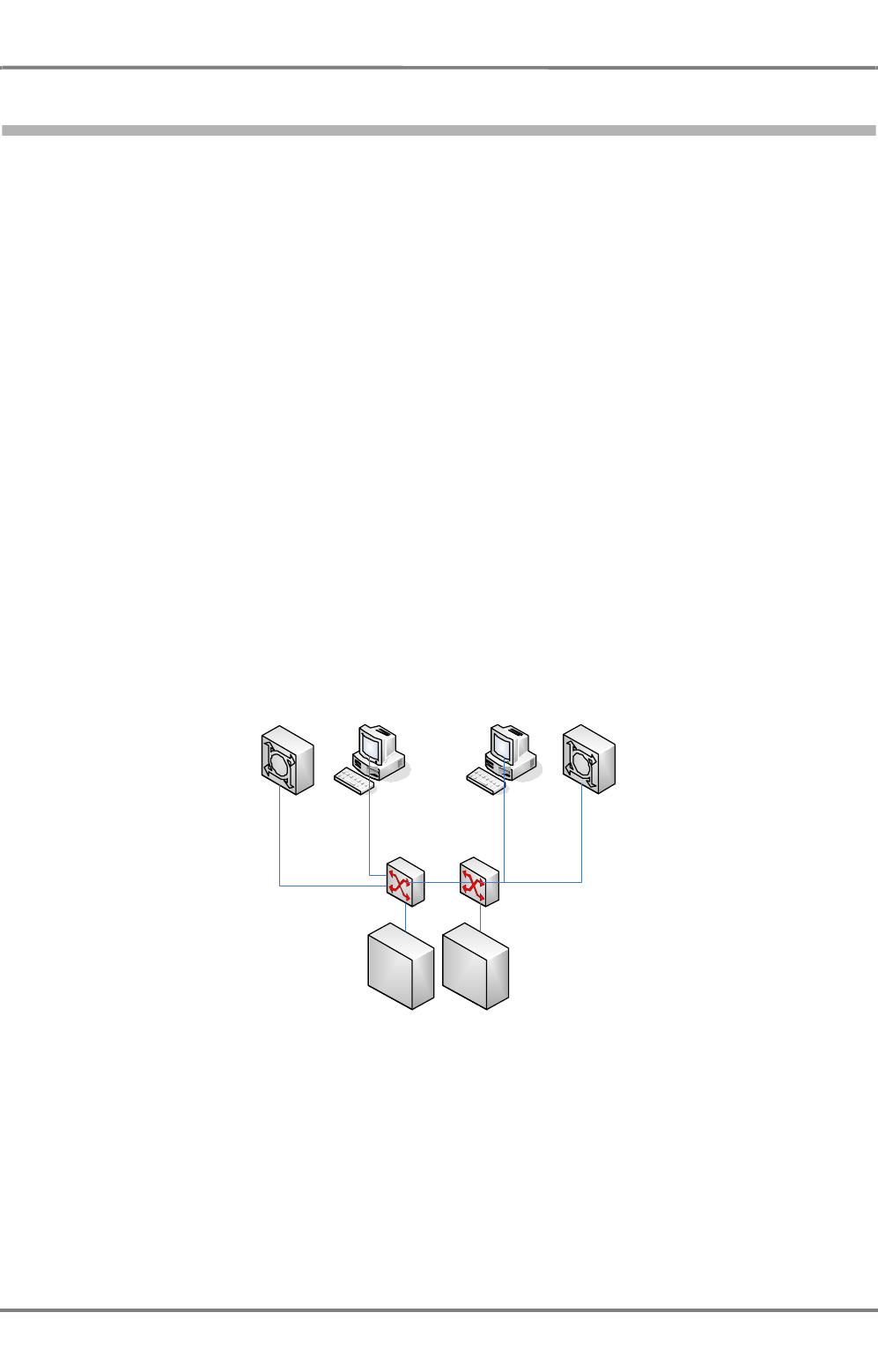
product range, e.g. a the minimum ship configuration in the figure below, the so-called IMO set:
Fig. I / 2 Minimum installation – IMO set
OutstationOutstation
Bridge Bridge IP Radar
IP Radar
NACOS Platinum
ED 3100 G 140 / 04 (2011-11)
Operating Instructions
I-3 NACOS Platinum System Description
I General.fm / 10.11.11
I-24
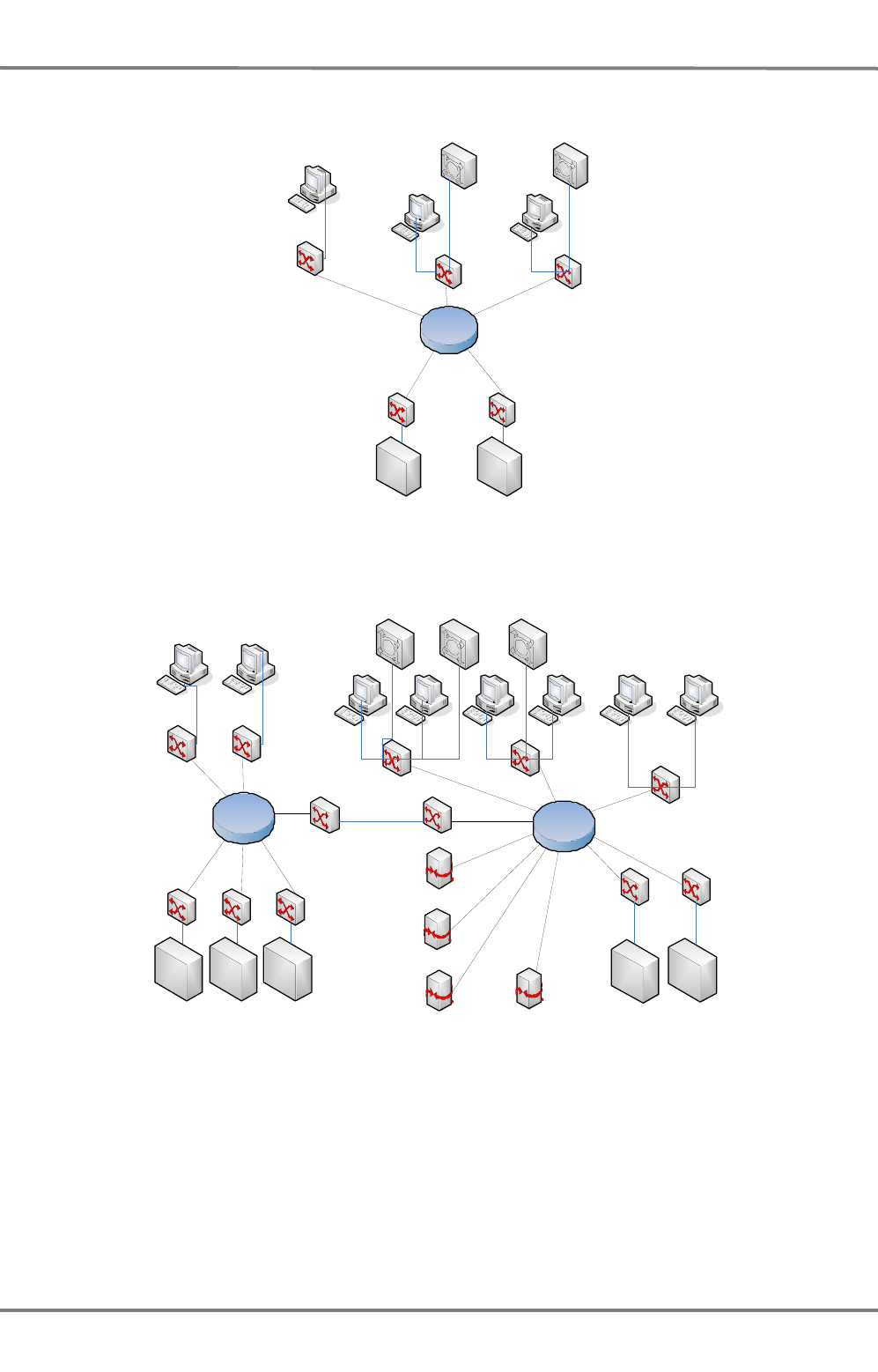
At a higher expansion stage, a small-ship configuration could include RADAR as well as Navigation &
Automation:
Fig. I / 3 Example of a small-ship installation
An example for a complex installation on a large ship is shown in the following figure below:
Fig. I / 4 Example of a large-ship installation
Outstation Outstation
ECR
Bridge Bridge
IP RadarIP Radar
Gateway to CCTV
Gateway to Infotainment
Gateway to Communications
Gateway to A dmin/C4
Outstation OutstationOutstation Outstation Outstation
ECR ECR
Bridge Bridge Bridge Bridge Office Office
IP RadarIP Radar IP Radar

ED 3100 G 140 / 04 (2011-11)
Operating Instructions
I-3 NACOS Platinum System Description
I General.fm / 10.11.11 I-25
NACOS Platinum
3.3 Applicable Standards
This section lists the standards and class rules the NACOS Platinum is complies with. Basically, the
NACOS Platinum meets the relevant IMO INS and IMO IBS requirements. The individual standards are
listed in the following.
Table I / 2 Applicable Standards
Application Applicable standards
RADAR IEC 60945 / IEC 61162 / IEC 62288 / IEC 62388 / MSC.192(79)
ECDIS IEC 60945 / IEC 61162 / IEC 62288 / IEC 61174 / MSC.232(82)
Heading Control System IEC 60945 / IEC 61162 / IEC 62288 / ISO 11674
Track Control System IEC 60945 / IEC 61162 / IEC 62288 / IEC 62065 / MSC.64(69) Annex 2

NACOS Platinum
ED 3100 G 140 / 04 (2011-11)
Operating Instructions
I-3 NACOS Platinum System Description
I General.fm / 10.11.11
I-26

ED 3100 G 140 / 04 (2011-11)
Operating Instructions
I-4 Multi Function Display
I General.fm / 10.11.11 I-27
NACOS Platinum
4 Multi Function Display
This chapter describes the MFD and the relevant peripheral devices which are required or optional equip-
ment to operate the NACOS Platinum.
NACOS Platinum
ED 3100 G 140 / 04 (2011-11)
Operating Instructions
I-4 Multi Function Display
I General.fm / 10.11.11
I-28
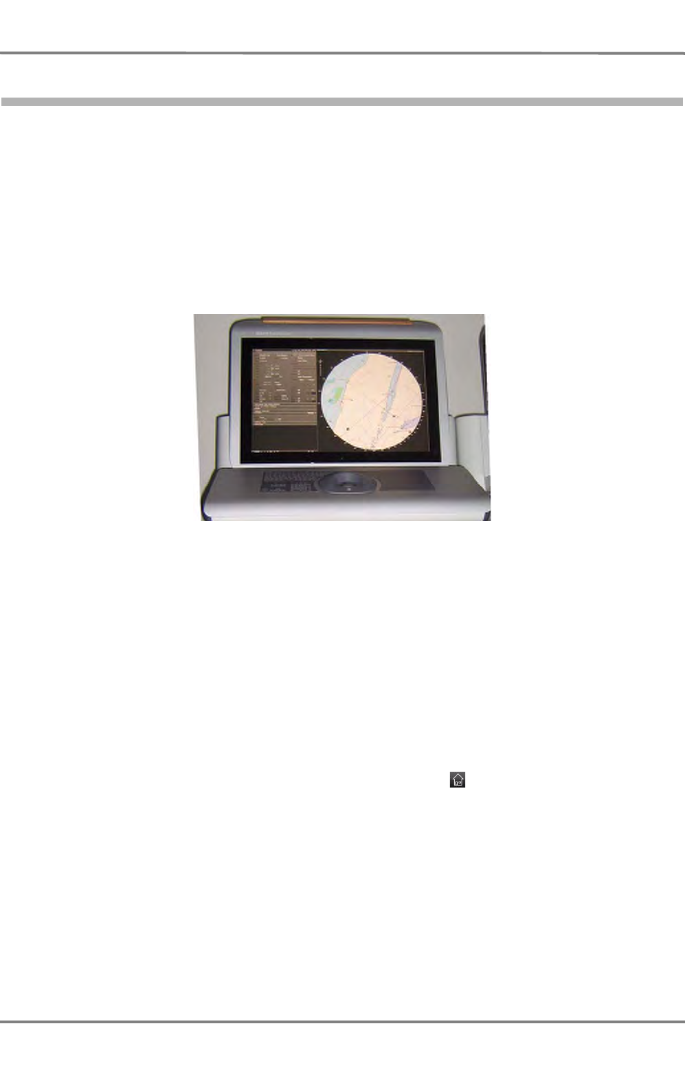
4.1 General System Description MFD
The NACOS Platinum applications are operated using standardised MFDs. A MFD is based on a Personal
Computer running under Windows 7 which is used for input and output of data of the NACOS Platinum
using the graphical user interface (GUI) of Windows. From a MFD, you will have access to the applica-
tions installed in your NACOS Platinum. The GUI handling is the same on each MFD, i.e. the workplaces
aboard are standardised. All applications can be made available at any MFD. See chapter 3.2 on page I-
23.
MFDs are installed in the consoles aboard, and they are equipped with a 22" or 26’’TFT monitor and a
trackball. Optionally, MFDs can also be equipped with mouse and keyboard. See chapter 4.2 on page I-
29.
Fig. I / 5 MFD
The GUI is based on Microsoft Windows 7. However, you do not have direct access to Windows so that
the MFD cannot be used like a normal PC, e.g. to install software and run applications other than the
applications related to the NACOS Platinum.
In these operating instructions, we assume that you are reasonably familiar with basic Windows functions
such as window operations, dialogue handling, menu and button operation, selecting list items or
options, and so on. Nevertheless, many of the screen elements and basic operations are explained in
these operating instructions. See chapter 5 on page I-45, which explains features which are specifically
important for operation of the NACOS Platinum.
When the MFD is started, a basic screen is displayed, which is referred to as Super Home from where
you have access to all functions and information which are available on the specific MFD. If the MFD is
already running, select Super Home from the main menu or click in the menu bar to switch to Super
Home. See chapter 5.1 on page I-46.

ED 3100 G 140 / 04 (2011-11)
Operating Instructions
I-4 Multi Function Display
I General.fm / 10.11.11 I-29
NACOS Platinum
4.2 Operating Devices
NACOS Platinum
ED 3100 G 140 / 04 (2011-11)
Operating Instructions
I-4 Multi Function Display
I General.fm / 10.11.11
I-30
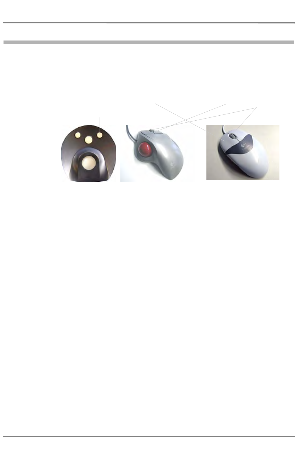
4.2.1 Pointing Devices – Trackball and Mouse
All user interface controls are operated by the mouse or trackball which is connected to the respective
MFD. Even if you are already familiar with using input devices like mouse or trackball, you will find one
or the other important note in this section.
Fig. I / 6 Possible pointing devices
To start an operating step move the pointer on the screen by moving the trackball or mouse. Move the
pointer to the desired position on the screen, e.g. to a text item, a numerical value, a symbol, or any
desired position e.g. on the PPI. The shape of the pointer changes when you point at different elements
on screen. The pointer’s shape depends on the application and the element you point at. See chapter I
- 5.10 on page 82.
When you point at a click-sensitive (clickable) element on screen then you can press and release (click)
one of the trackball keys to display information or activate a function. The possible types of clicks are
explained separately. See chapter I - on page 31. The specific effect of clicking depends on the key
used, the element you clicked, and the operating situation. This is described in the specific parts of these
operating instructions. Desktop trackball or mouse have two different buttons, DO and MORE key. The
functions of the DO and MORE keys are described in the following.
DO Key
The most frequently used of the keys is the DO key, i.e. the middle key on the built-in trackball and the
left button of the desktop trackball and mouse. Most elements on screen respond to this key by opening
a menu from which you can select frequently used functions.
☞ In these operating instructions, "clicking" always means pressing the DO key. When you have to
press the MORE key or the right mouse/trackball button, this will be explicitly explained in the
instructions.
Built-in
trackball Desktop
trackball Mouse
DO key
No function MORE key...
DO key MORE key
Scroll wheel
ED 3100 G 140 / 04 (2011-11)
Operating Instructions
I-4 Multi Function Display
I General.fm / 10.11.11 I-31
NACOS Platinum
MORE Keys
On the built-in trackballs the two keys are situated above the DO key, The right one is called MORE
key. The left key has no function. On the desktop trackball and mouse, this is the right button. The func-
tions of the MORE key depend on the element you point at on screen. In some cases pressing the MORE
key opens menus, in other cases additional information are displayed. However, not all elements which
can be operated by means of the DO key will also respond to the MORE key.
Scroll Wheel
If a scroll wheel is available, it can be used to scroll down lists or to zoom into or out of charts. Only
mouse and desktop trackball may be equipped with a scroll wheel.
Types of Clicks
In NACOS Platinum you point at elements on screen and click or press the MORE key to display infor-
mation or cause action. The following types of clicks are possible:
Table I / 3 Types of clicks in NACOS Platinum
Click Explanation
Single click of
left key or DO key Perform action. This means pressing and immediately releasing again the
DO key of the built-in trackball, or the left mouse or trackball key respec-
tively.
When you click on a button, this will start a process or open a dialogue.
when you click on dropdown menus, this will open the menu. In a menu,
to select an item, click on the item with a single click. A single click will also
select and thus highlight an entry in a list.
Double-click of
left key or DO key In tables, a double-click will open a cell for editing. A cursor is displayed,
and you can change the respective value like a text field. Editing resembles
editing cells in Microsoft Excel. An example for such a table is a waypoint
list that contains the waypoint number, name, position and some other
properties, which you can change in that table by double-clicking on the
cells.
When you click on a folder icon in folder structures, which you will find,
e.g., in the Machinery application, a double-click opens that folder and lists
the subordinated contents.
Press the MORE key or
right-click using mouse or
desktop trackball
Get information, in many cases via a context menu. This is used for
providing you with object-specific menu items, such as menus for properties
and maintenance. These functions also provide access to adjustments,
particularly in the Machinery application. Examples are: acknowledging
alarms, displaying properties, etc.
NACOS Platinum
ED 3100 G 140 / 04 (2011-11)
Operating Instructions
I-4 Multi Function Display
I General.fm / 10.11.11
I-32
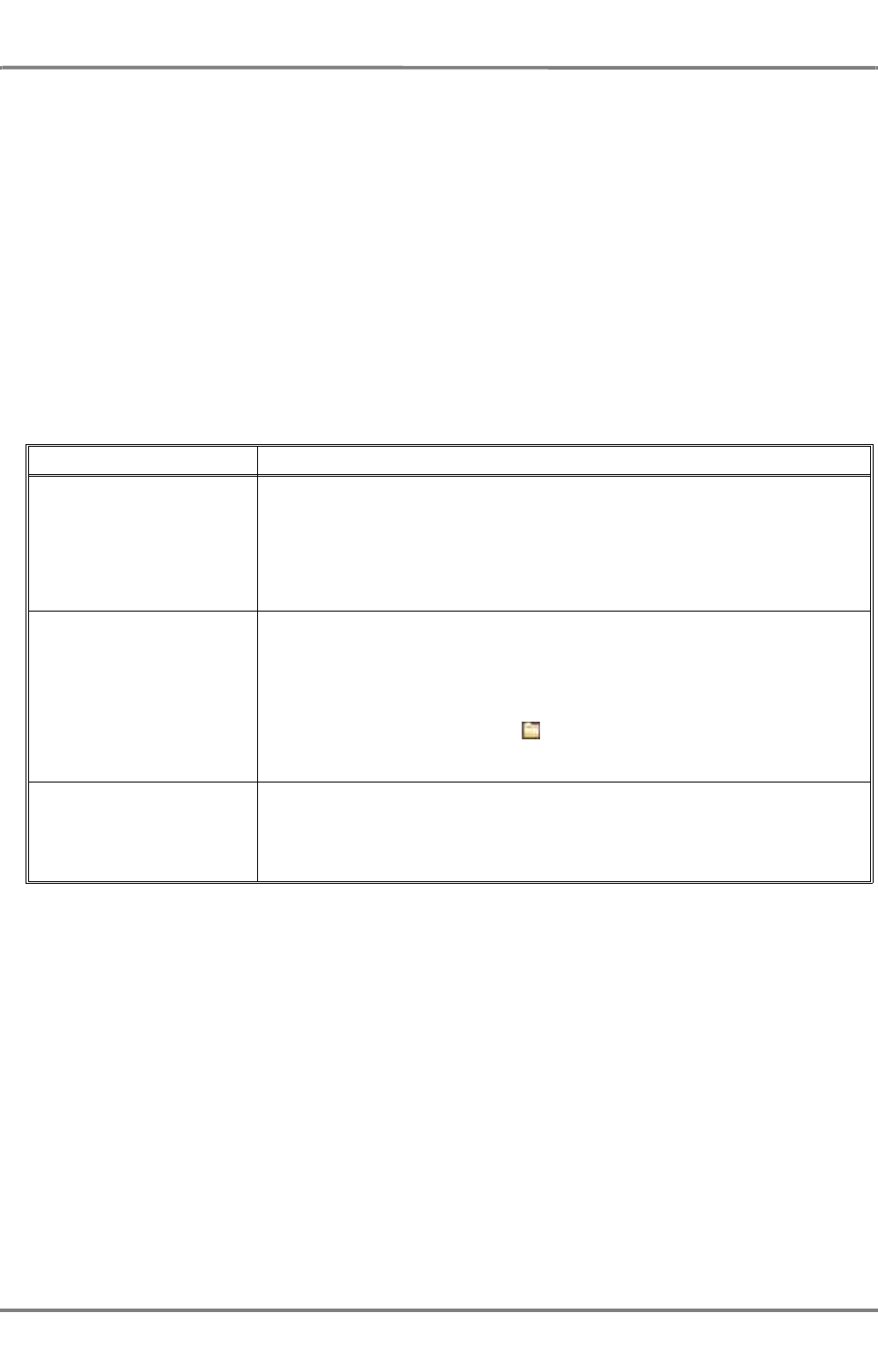
4.2.2 Keyboard
To enter alphanumerical values and also to operate the user interface, the MFD may be equipped with
a membrane keyboard, which is integrated in the console.
Fig. I / 7 Keyboard of a console
In some cases, an optional external keyboard is provided. For that purpose, a standard PC keyboard is
used. Depending on the application you are working with, the function keys in the top row may have
special functions. Please refer to the relevant descriptions of the individual applications. For example, in
the RADAR applications, function keys have different functions than in the Machinery application.
If no external keyboard is available at all, values can also be entered using the so-called onscreen
keyboard which is an optional feature of the NACOS Platinum user interface. However, this depends on
customisation. There may be a separate icon for the onscreen keyboard.
Fig. I / 8 Onscreen keyboard
You can use this keyboard to enter text and numeric values or press function keys, just as you do when
you use the physical PC keyboard. The onscreen keyboard thus emulates the PC keyboard and it can be
used if, for whatever reason, the PC keyboard does not work. Simply click on the buttons to enter the
respective letter or number, or activate the respective function of the key.
Note: For the RADAR application the left part and for the TRACKPILOT the right part of the MFD console
can be equipped with a dedicated keyboard panel. See the respective chapters for details.
ED 3100 G 140 / 04 (2011-11)
Operating Instructions
I-4 Multi Function Display
I General.fm / 10.11.11 I-33
NACOS Platinum
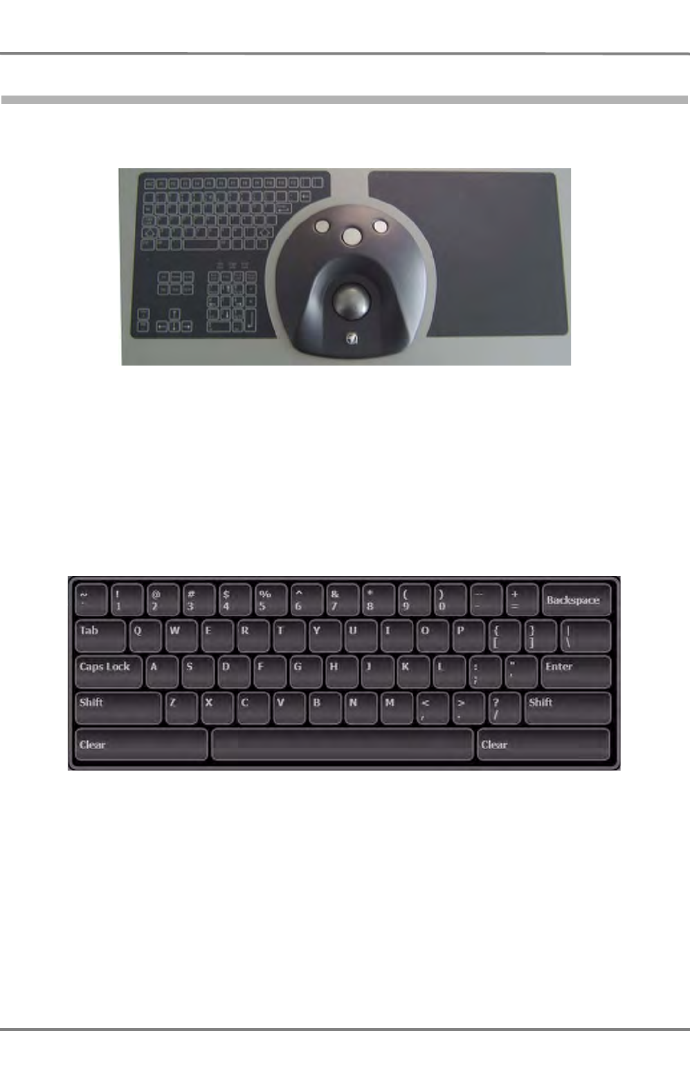
4.2.3 The ASCII Keyboard
Fig. I / 9 The Optional ASCII Keyboard
The MFD can be equipped with a ASCII keyboard in the console. It works like a common computer
keyboard, except for the fact that the backlight can be dimmed and that the location of the key-groups
is different and that the location of the key-groups is different.
Backlight dimming
NACOS Platinum
ED 3100 G 140 / 04 (2011-11)
Operating Instructions
I-4 Multi Function Display
I General.fm / 10.11.11
I-34
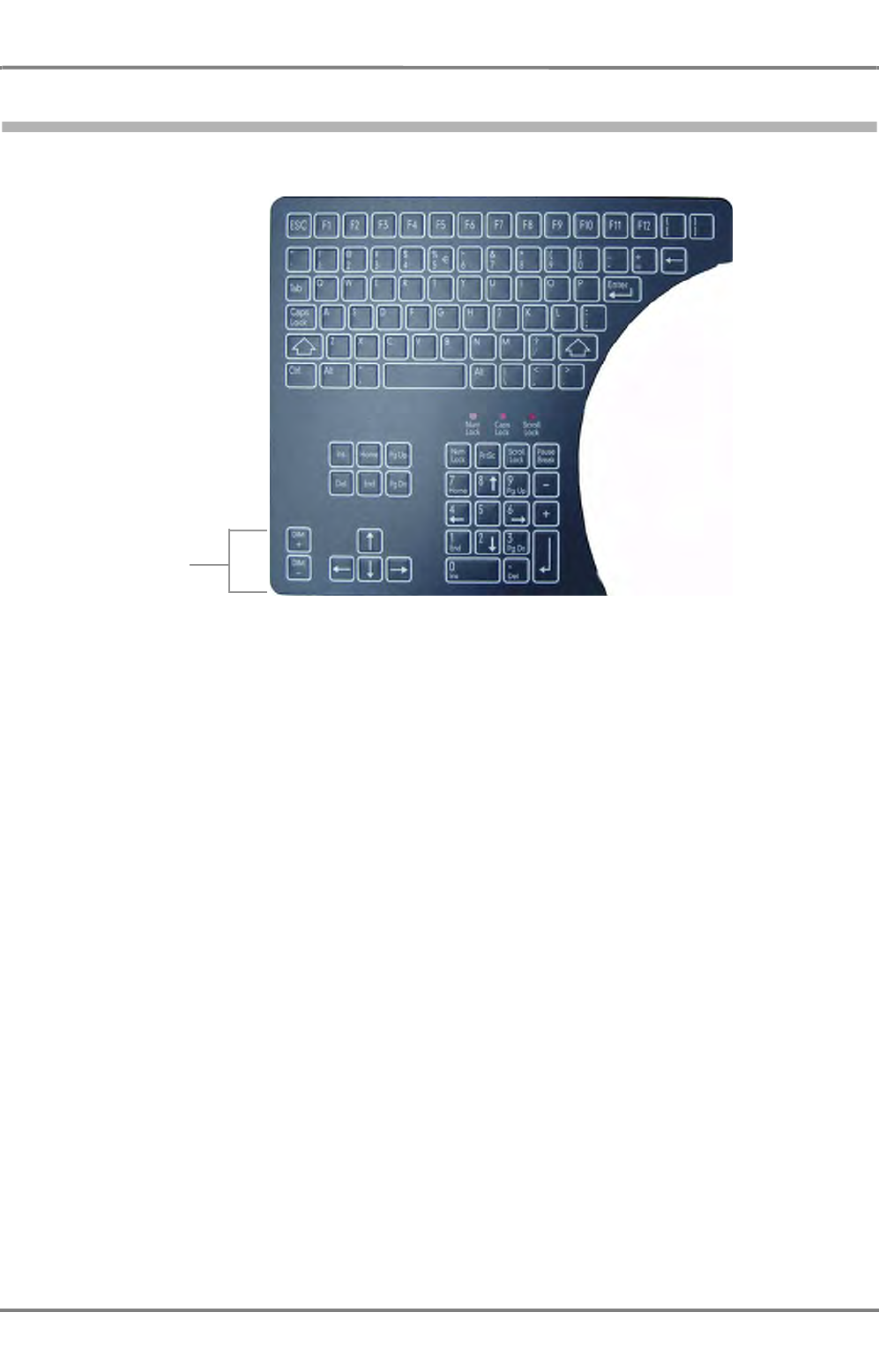
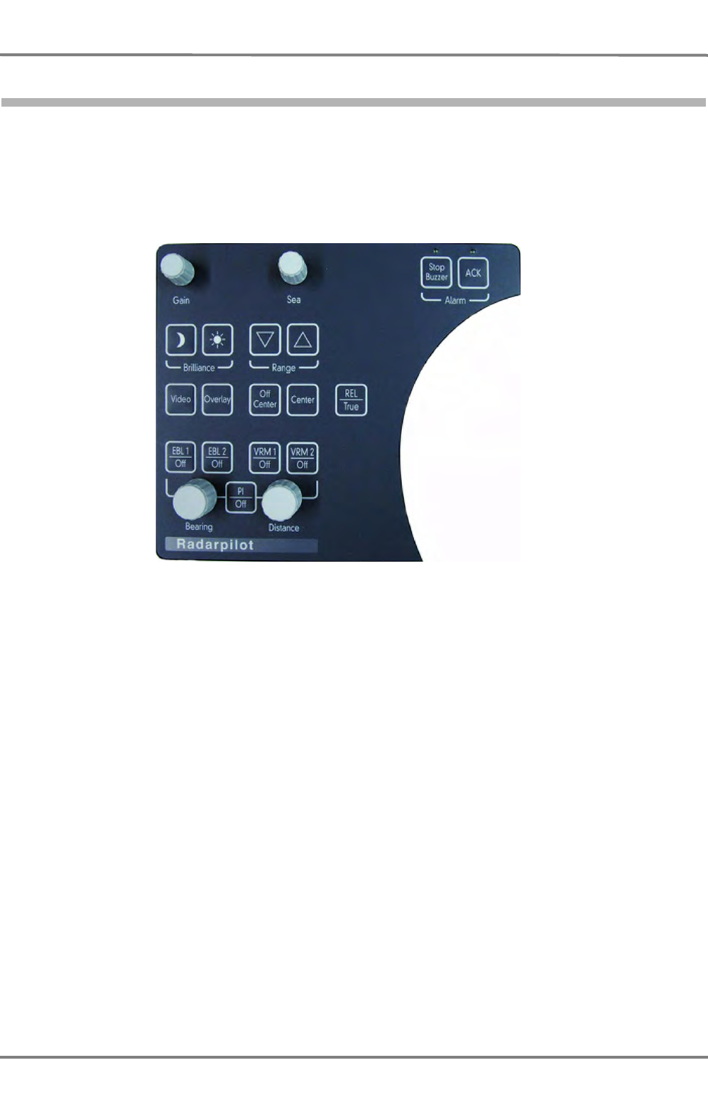
4.2.4 The RADAR Keyboard
Fig. I / 10 The RADAR Keyboard
ED 3100 G 140 / 04 (2011-11)
Operating Instructions
I-4 Multi Function Display
I General.fm / 10.11.11 I-35
NACOS Platinum
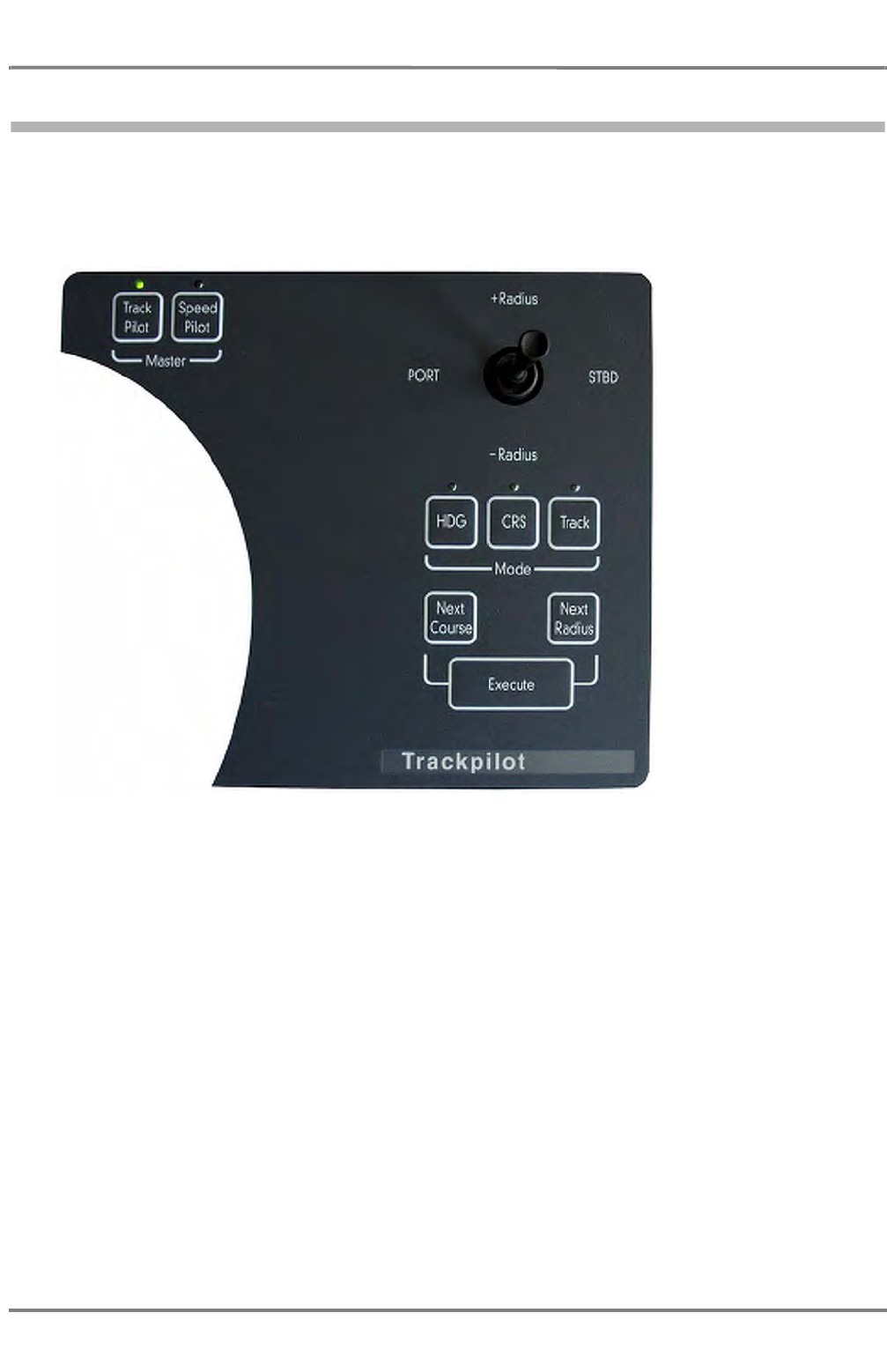
4.2.5 The TRACKPILOT Keyboard
Fig. I / 11 The Trackpilot Keyboard

NACOS Platinum
ED 3100 G 140 / 04 (2011-11)
Operating Instructions
I-4 Multi Function Display
I General.fm / 10.11.11
I-36
4.3 TFT Monitor
The NACOS Platinum user interface is displayed on a 22" or 26’’ TFT monitor which is an integrated part
of the MFD. The monitor is switched on and off automatically together with the MFD. To adjust the
monitor’s settings, use the software functions and controls provided. See chapter I - 5.3.1 on page 52.

ED 3100 G 140 / 04 (2011-11)
Operating Instructions
I-4 Multi Function Display
I General.fm / 10.11.11 I-37
NACOS Platinum
4.3.1 Nominal Viewing Distance
The monitors are designed according to IEC 62388. In chapter 6.13.2 of this test standard a maximum
pixel pitch of 0.29 mm per metre of nominal viewing distance (1 min of arc) is required. Both monitors
have a pixel pitch of less than 0.29 mm. The requirement is fullfilled.
Further-on above standard references to IEC 60945, Clause 4, where a minimum text height is required
with 3.5 mm per metre of nominal viewing distance and at least 11 pixels.
The RADARPILOT as well as CHARTPILOT application provide text heights on both monitors (independent
of monitor size) as follows:
- "Large font with 5.5 mm
- "Medium size font with 4.5 mm
- "Normal size font with 3.5 mm
- "Small font with 2.5 mm
The small font is not used for navigation related tasks.
☞ The normal size font is used for navigation and determines the nominal viewing distance with 1
metre for both monitors.
This is sufficient for sitting positions in front of one of the workstations (typically 0.8 metre) as well as
for a standing position in front of the centre steering console (typically 1.0 metre). In this case the
console has a depth of max. 0.8 metre.

NACOS Platinum
ED 3100 G 140 / 04 (2011-11)
Operating Instructions
I-4 Multi Function Display
I General.fm / 10.11.11
I-38
4.3.2 Colour Distortions on Monitors with Flat Screens (TFT Monitors)
If the display content on a TFT monitor has remained unchanged for a long period of time and is then
replaced by a different display, an effect can occur which is known as "ion spotting" in the case of
cathode ray tubes: the previous display is still faintly visible in the form of discoloration. In the case of
TFT monitors, in contrast to monitors with cathode ray tubes, this effect is reversible and therefore
cannot be regarded as a defect. If the monitor is operated for a long time (several hours or days) with
a different display, the discoloration disappears.

ED 3100 G 140 / 04 (2011-11)
Operating Instructions
I-4 Multi Function Display
I General.fm / 10.11.11 I-39
NACOS Platinum
4.3.3 Printers
For the different printouts of the NACOS Platinum, two different types of printers are required:
- Line printers for logs and other continually printed lists
- Page printers for complete reports which are printed in one go
Refer to the parts of the operating instructions describing the individual applications.
NACOS Platinum
ED 3100 G 140 / 04 (2011-11)
Operating Instructions
I-4 Multi Function Display
I General.fm / 10.11.11
I-40
4.4 Startup and Shutdown of MFDs
☞ The NACOS Platinum and the related consoles and the electronics equipment are permanently up
and running. They are only completely shut down by qualified authorised service personnel in case
of servicing and repair. The system components are then separated from the mains using a main
switch on the bridge. When switching on the mains supply again, the equipment will startup auto-
matically without further user action.
This section describes how to use the shut-down function, if this is required, e.g. if the power supply has
to be switched off during a dockyard period, or if an individual MFD shall be switched off for specific
reasons. Proceed as follows to switch off a MFD:
1. Press [Alt] + [F4], or click the Menu button and then Shut Down.
2. Enter the required password.
3. In the window which is displayed, select Shut Down and click OK.
The other options Reboot or Log off can be used to re-boot the MFD immediately or to log off
and on again.
4. Separate the unit from the mains using the mains switch on the bridge.
This way, the NACOS Platinum program is terminated and the PC is shut down. The display will be
switched off automatically.
To switch on the MFD use the main power switch (if appl., refer to the drawings in the delivery docu-
ments). It will automatically start up and run in normal operating state, Super Home is displayed. If the
MFD is already up and running and displaying a screensaver, just move the trackball slightly to display
the graphical user interface of the MFD.
As long as the ship is at sea and in operation, the NACOS Platinum must be fully
operational, i.e. the NACOS Platinum and its applications must not be shut down.
UPS systems must not be deactivated.
Never switch off a MFD without having completed the described shutdown proce-
dure. The TFT display will probably function in a normal manner when just
switching off the power and then switching it on again. However, and this applies
to all types of PCs used: if, at the moment it is switched off, the PC accesses the
hard disk, the hard disk might be permanently damaged resulting in system
failure of the MFD and loss of data.

ED 3100 G 140 / 04 (2011-11)
Operating Instructions
I-4 Multi Function Display
I General.fm / 10.11.11 I-41
NACOS Platinum
4.5 Basic Settings

NACOS Platinum
ED 3100 G 140 / 04 (2011-11)
Operating Instructions
I-4 Multi Function Display
I General.fm / 10.11.11
I-42
4.5.1 Adjusting the Display
Use the brightness control symbols in the title bar( and ), in the Brilliance/Data Area menu or the
keys on the console to toggle between the available color schemes. See chapter I - 5.3.1 on page 52.
With these keys any manual setting done with the sliders is reset to the factory-set default values.
A MORE-click on the symbols opens the Brilliance/Data
Area menu.
With the Brilliance slider, the overall brilliance of the monitor
can be set. In parallel, the brightness of the backlight illumi-
nation of the radar and/or TRACKPILOT keyboard is set. It is
not possible do dim the ASCII-keyboard from here.
With the Data Area slider, the brightness of the elements of
the sidebar can be set seperately.
The symbols and have the same functions as described above.
The corresponding keys on the console are:
☞ If the screen appears completely dark due to a brilliance
setting which is unsuitable for the actual ambient light
and the symbols are no longer visible, just move the
mouse pointer into the top left corner and press a few
times the DO button. Brilliance will light up again.
☞ In the PPI/or chart area the brilliance of the scales or the user symbols can be set seperately. Use
a MORE-click in the PPI/or chart area in order to open the context menu and set the appropriate
sliders.
Brilliance
d
Æ
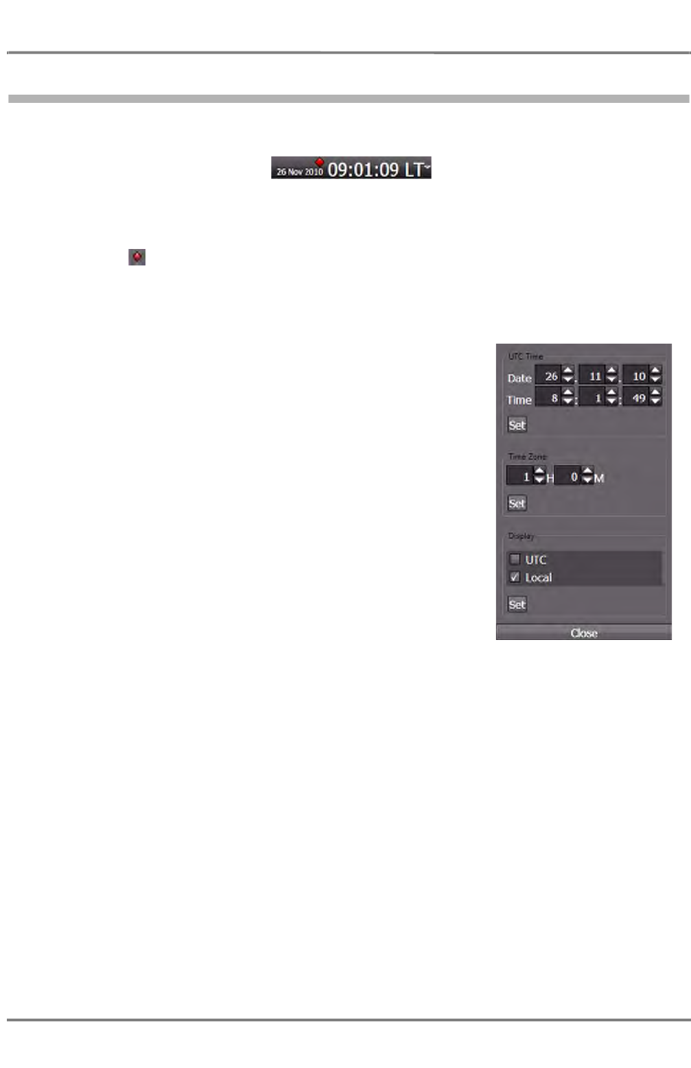
ED 3100 G 140 / 04 (2011-11)
Operating Instructions
I-4 Multi Function Display
I General.fm / 10.11.11 I-43
NACOS Platinum
4.5.2 Setting Date and Time
Both date and time will be displayed permanently in the title bar: .
Fig. I / 12 Date and Time Display
The symbol indicates that external synchronization of system time is not available – so that system
time is running on the internal clock in the time-master DPU. Once the external time source becomes
available again, the time is adjusted accordingly, and the red symbol dissapears.
To set Date/Time klick on the small arrow at the very right. A
dialog window opens.
The operation of the controls is self-explanatory, do not forget to
klick on Set after having corrected the values in order to apply
them to the system.
Click on Close to leave the dialog.

NACOS Platinum
ED 3100 G 140 / 04 (2011-11)
Operating Instructions
I-4 Multi Function Display
I General.fm / 10.11.11
I-44

ED 3100 G 140 / 04 (2011-11)
Operating Instructions
I-5 NACOS Platinum Graphical User Interface
I General.fm / 10.11.11 I-45
NACOS Platinum
5NACOS Platinum Graphical User Interface
This section describes the Graphical User Interface (GUI) of the NACOS Platinum. This includes the basic
screen layout starting from the moment the system is first switched on, as well as the basic screen
elements and controls, general screen navigation, and how to switch between the individual NACOS Plat-
inum applications.
☞ The descriptions of the user interface in this chapter start from very general, i.e. with the big areas
and elements on screen which are then broken down to detailed explanations on specific items on
screen in the subsequent sections. If you are not familiar at all with the basic Windows controls and
mouse/trackball pointers, it might be useful to read the respective sections before starting here. See
chapter I - 5.9 on page 69.
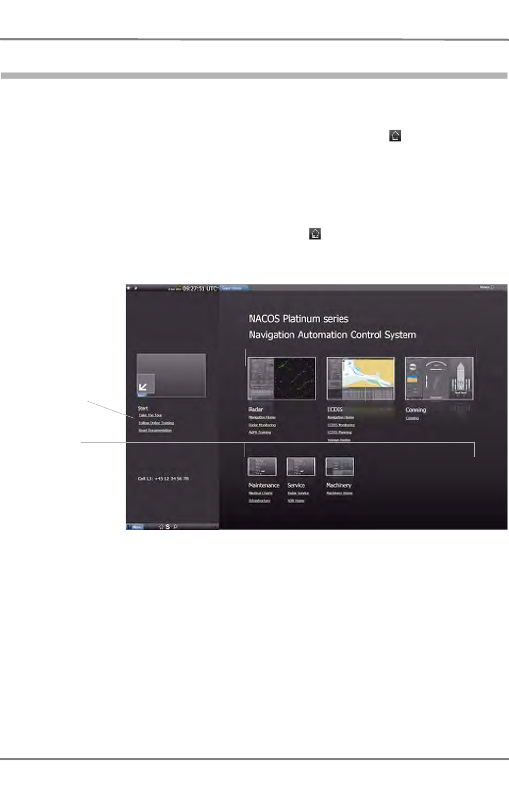
NACOS Platinum
ED 3100 G 140 / 04 (2011-11)
Operating Instructions
I-5 NACOS Platinum Graphical User Interface
I General.fm / 10.11.11
I-46
5.1 Super Home
Super Home is the first screen that is displayed on screen after start-up of the MFD. Super Home will
help you in quickly starting the main applications, and provide help in finding specific functions through
the homepages of the individual applications. When you are working with the system, you can return to
Super Home by using the Super Home shortcut in the main menu or the button. Super Home
provides links to:
- All main applications´ homepages: RADAR, ECDIS monitoring, ECDIS planning, Conning and
Machinery / Automation home
- Secondary applications like AIS, Autopilot, Maintenance and possibly third party applications
- Documents that help you getting started.
Super Home has a title bar and menu bar. Clicking on the button will open the Super Home page
regardless of the current active application. Title bar and menu bar are described separately. See chapter
5.3 on page I-51.
Fig. I / 13 Example of Super Home
The top row of applications of the Super Home page displays the main or primary applications that are
installed in the system, in the example: RADAR, ECDIS, Machinery, and Conning. The thumbnail pictures
of the applications are clickable and will link to the respective application. For example, if you click on
the RADAR thumbnail, this will open the RADAR application.
The first link below the thumbnail of a main application is the link to the homepage of the application.
Additional links will lead you to important functions in the applications. The second line of thumbnails
contains shortcuts to groups of functionality that are considered a logical group or additional application.
For familiarization with the product, it is possible to select from the quick-links.
- Take the Tour opens a presentation in which the advantages and functionality of the PLATINUM
are presented.
Main
applications
Logical groups
and additional
applications
Quick access to
additional infor-
mation
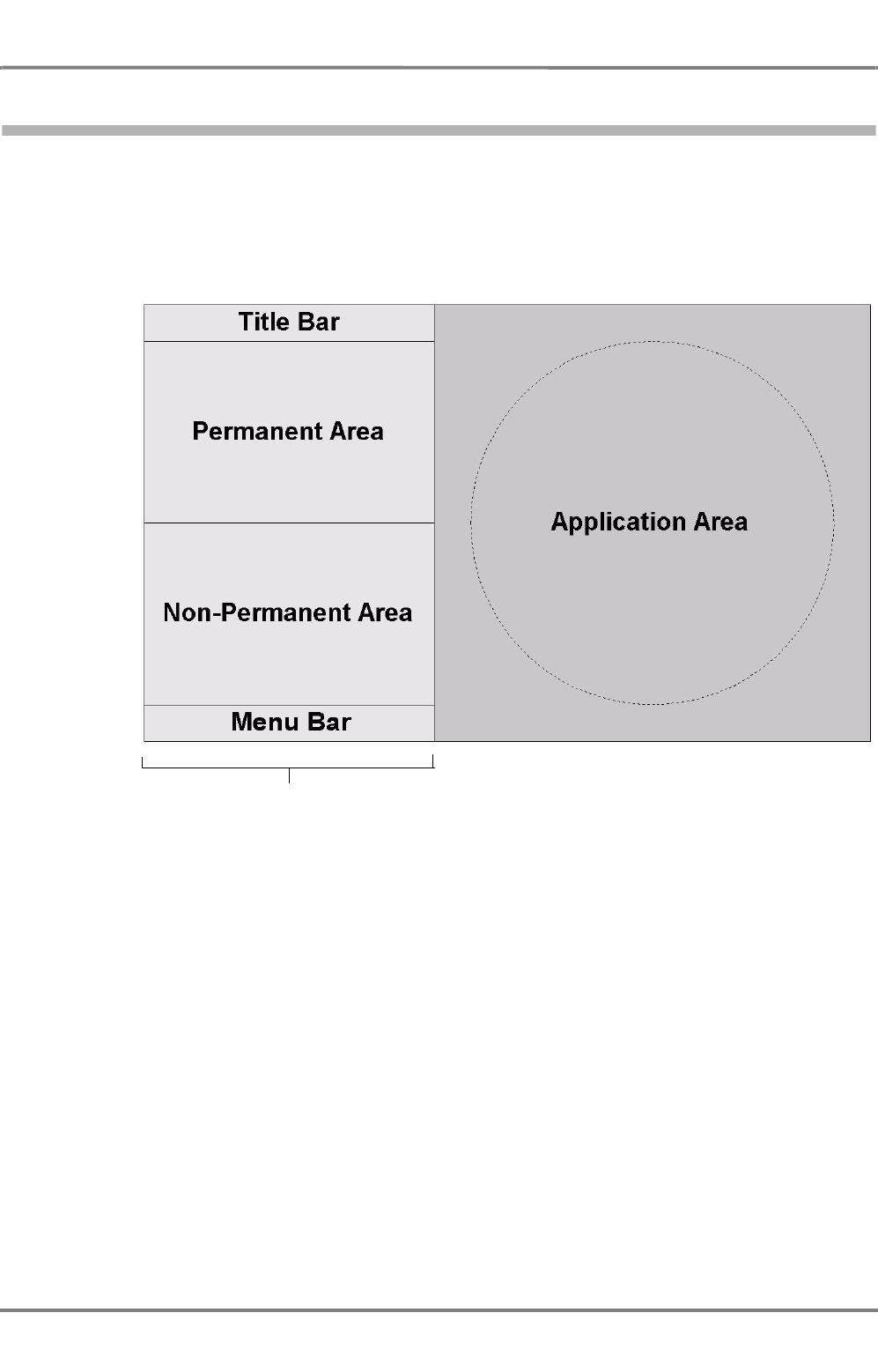
ED 3100 G 140 / 04 (2011-11)
Operating Instructions
I-5 NACOS Platinum Graphical User Interface
I General.fm / 10.11.11 I-47
NACOS Platinum
5.2 Screen Layout
The main page of an application consists of two main areas: the sidebar and the application area. The
sidebar on the left provides access to details and functions of the applications. The sidebar is described
separately. See chapter 5.3 on page I-51. The application area located on the right shows the main
window of the active application. It can show the radar PPI, the ECDIS chart or Machinery mimics etc.
The general behaviour of the application area is described separately. See chapter 5.4 on page I-59.
Fig. I / 14 General screen layout of the NACOS Platinum (RADAR Mode)
The general screen layout, especially the size of the different areas, may vary betwen the different avail-
able applications.
Sidebar
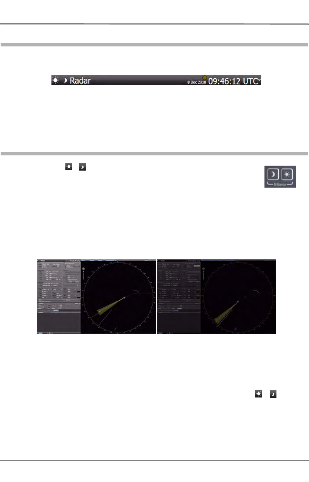
NACOS Platinum
ED 3100 G 140 / 04 (2011-11)
Operating Instructions
I-5 NACOS Platinum Graphical User Interface
I General.fm / 10.11.11
I-48
5.2.1 Title Bar
The title bar provides information and functions which are permanently available in the system.
Fig. I / 15 NACOS Platinum title bar of RADAR application
The figure above shows an example of the title bar with the RADAR application being the active appli-
cation. The information and functions provided are explained in the following.
5.2.1.1 Brilliance
You can use the / buttons in the top left corner to toggle between the available
color schemes for different ambient light conditions. Alternatively you can use the keys
on the console or the appropriate entry in the menu.
Five different color schemes are available for different ambient light conditions. The
brilliance is toggled between 5%, 20%, 60%, 80% and 100%.
The Data Area brilliance setting is not affected by these cobtrols. But it changes accordingly, because
the brilliance setting is relevant for the whole screen.
☞ The brilliance of the monitor does not change stepwise, in fact it changes smoothly from the
previous setting to the actual desired value.
Fig. I / 16 Color schemes of the Color & settings
The buttons are located in the top left corner which is easy to remember. This way, when the screen is
hardly readable due to changing light conditions, you will be easily able to find the / buttons at
the fixed and easy to find location.
100% 20%
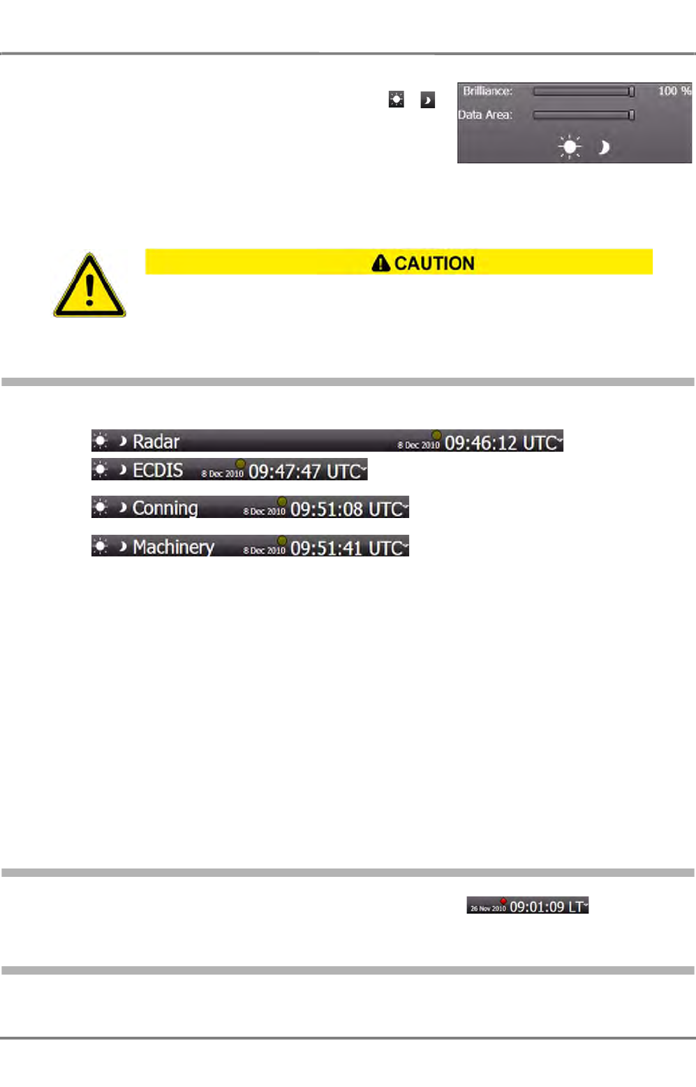
ED 3100 G 140 / 04 (2011-11)
Operating Instructions
I-5 NACOS Platinum Graphical User Interface
I General.fm / 10.11.11 I-49
NACOS Platinum
However, you can also individually adjust the brilliance of the
screen. If you press the MORE key (right-click) on the /
button to open the Brilliance menu. To adjust the settings,
click on the right or left of the slider or drag the slider. The new
value is shown on the right and the screen’s settings are
adjusted accordingly.
☞ There are no knobs or other controls on the monitor(s) to adjust the brightness.
5.2.1.2 Active Application Title
The title bar displays the name of the application which is currently active in the application area, e.g.
Fig. I / 17 Active Application Title
5.2.1.3 Date and Time
Both date and time will be displayed permanently in the title bar:
5.2.1.4 Alive Indication
The use of the brightness controls may inhibit visibility of information, particularly when
using the night color tables!

NACOS Platinum
ED 3100 G 140 / 04 (2011-11)
Operating Instructions
I-5 NACOS Platinum Graphical User Interface
I General.fm / 10.11.11
I-50
There are different possibilities available to verify the alive status of the MFD which are listed and
explained below.
The Time Display
The system provides feedback that it is still active and operating, i.e. alive. This is specifically indicated
on each MFD in the title bar of the HMI by the seconds changing in the time display.
If picture freeze occurs, all data on the screen as well as the display of the seconds will be frozen, so
that the operator is able to notice this fault.
The Cursor and HMI
Picture freeze caused by the computer or the graphics adapter of the MFD can also be recognized by the
fact that moving the trackball or the mouse does no longer change the cursor position on the screen.
If the computer or its application software has a severe fault it can also happen that the cursor is still
moving but a click on any HMI element (for instance an operable button on the screen) is no longer
working correctly.
The RADAR Video
The transmission of the radar video from a connected transceiver to the MFD is monitored continuously.
If the connection to the transceiver is disturbed or completely lost, the respective alarm messages
describing the reason for the fault are given (See chapter 7.15 on page A-81 for details).
If the refresh of the radar video is not possible, the alarm No RADAR Video is issued; the video in the
PPI is cleared and will no longer be updated.
If no such alarm is indicated and you want to check the alive status of the radar transmission and the
PPI update you should switch off all signal processing of the radar video, increase the video gain to
maximum in order to visualize all targets and eventually clutter in the vicinity, or - as a minimum - make
the video noise visible on the PPI. If the video noise is visible and is changing at each antenna rotation,
this part of the system is alive and operable.
In order to make the rotating antenna sweep visible, you can
- "Step up and down with the radar range, or
- "Change the video gain between minimum and maximum.
In both cases the update of the video sectors on the PPI should be observable.
The Monitor
A green LED at the lower right corner of the MFD monitor indicates the running connection to the MFD
computer. If the connection is lost or disturbed, the LED will stay green but start flashing once per
second and the screen will normally become dark. If the LED changes to orange the monitor is in stand-
by mode waiting for sync signal, red indicates the switched off status. The LED will flash red in case of
excessive temperatures.
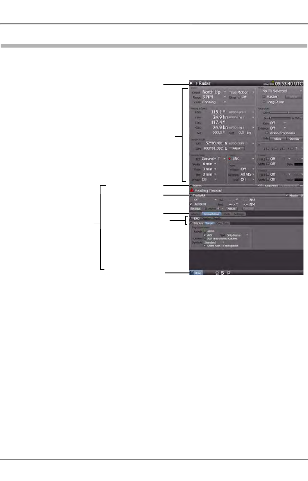
ED 3100 G 140 / 04 (2011-11)
Operating Instructions
I-5 NACOS Platinum Graphical User Interface
I General.fm / 10.11.11 I-51
NACOS Platinum
5.3 Sidebar
The width of the sidebar in each application is fixed, but it varies from application to application. The
sidebar consists of a permanent area, a non-permanent area, title bar and a menu bar, which are
explained in the following sub-sections.
Fig. I / 18 RADAR sidebar
Permanent area
Menu bar
Alarms Expander
Non-permanent area
Title bar
TRACKPILOT
Expander
Tabs
Expanders of the Tab
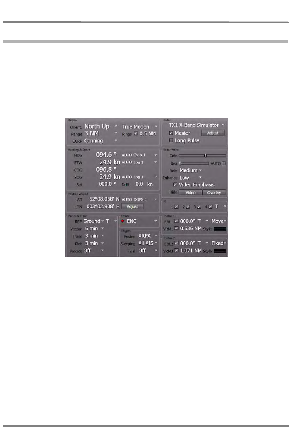
NACOS Platinum
ED 3100 G 140 / 04 (2011-11)
Operating Instructions
I-5 NACOS Platinum Graphical User Interface
I General.fm / 10.11.11
I-52
5.3.1 Permanent Area
The upper half of the sidebar is the permanent area. It shows status information and controls that are
mandatory according to regulations and thus must be permanently visible. In addition, the permanent
area can show information that is not mandatory but which you would expect to be permanently visible
or that are de facto standards. This area can never be overlapped or hidden by permanent pop-ups or
dialogue windows.
The height of the permanent area varies between the applications since some NACOS Platinum applica-
tions require more permanently visible information that others. For instance, RADAR requires more
permanent controls than the Machinery application. The figure below shows the permanent area of the
RADAR application:
Fig. I / 19 Sidebar – permanent area of the RADAR application
The RADAR application has the largest permanent area in the system since it requires the most manda-
tory controls. The RADAR permanent area is divided into two columns containing various groups. The
following information are provided in the groups:
- Display
containing orientation, motion, range and reference controls.
- Heading and Speed (of own ship).
Drift is not mandatory but it is included based on an early investigation into S-mode requirements.
- Position
- Vector and Trails
- Chart
- Targets
- RADAR
containing the radar transceiver controls

ED 3100 G 140 / 04 (2011-11)
Operating Instructions
I-5 NACOS Platinum Graphical User Interface
I General.fm / 10.11.11 I-53
NACOS Platinum
- RADAR Video
containing the video display controls
- Electronic Bearing Lines (EBL), Variable Range Markers (VRM) and Parallel Indes Lines (PI).
Alarm icons in front of a value indicate that the respective value is in alarm or warning status. See
chapter I - 5.9.12 on page 81.
The buttons are push buttons used to toggle between hiding and displaying
the radar video and overlay.
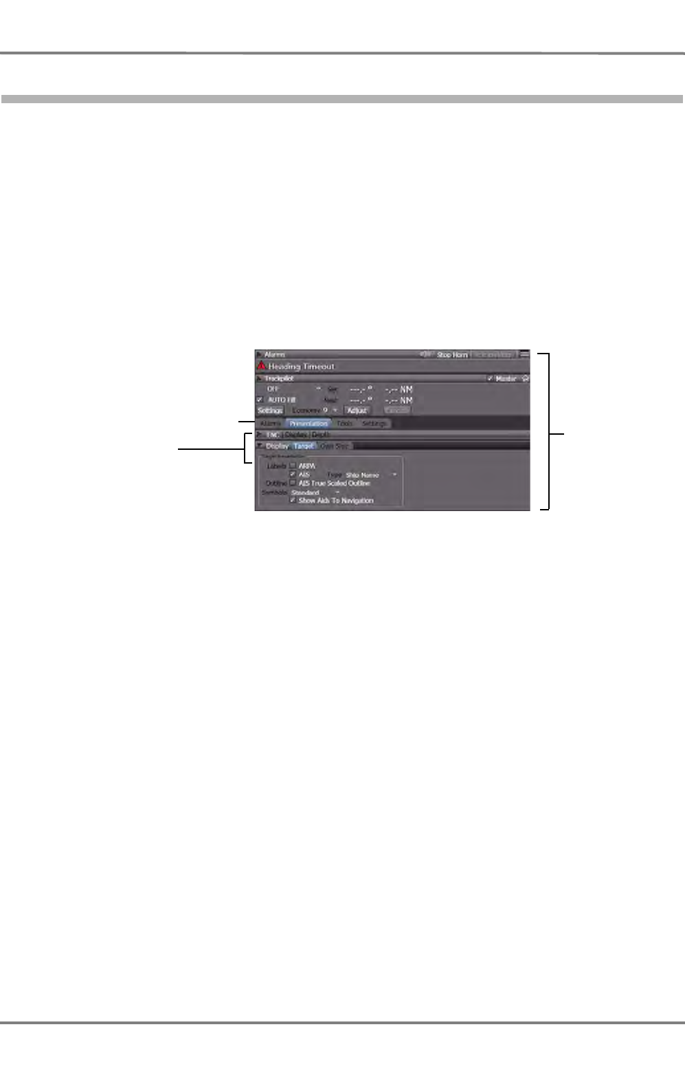
NACOS Platinum
ED 3100 G 140 / 04 (2011-11)
Operating Instructions
I-5 NACOS Platinum Graphical User Interface
I General.fm / 10.11.11
I-54
5.3.2 Non-Permanent Area
The lower half of the sidebar is the non-permanent area. It shows status information, parameters, tools
and controls. Some expanders are constantly visible, some can be hidden. See table below for details.
The expanders are grouped and stacked by means of so-called tabs. Click on a tab to view the subordi-
nated expanders. Using expanders you can expand and collapse, i.e. display and hide a variety of views,
controls or setting screens. The height of the non-permanent area is flexible and depends on the size of
the permanent area. If an opened expander exceeds the available space, a scrollbar is provided to scroll
up and down the contents of parts of the non-permanent area or to scroll left/right within parts of
expanders.
The controls displayed in the non-permanent area depend on the active application. For instance, the
RADAR application will display various settings screens. Machinery includes a navigation tool to browse
through large sets of mimic screens. The figure below shows an example of the non-permanent area of
the RADAR and ECDIS application:
Fig. I / 20 Sidebar – example of the non-permanent area of the RADAR application
The Alarm line expander and the optional TRACKPILOT expander have a permanent bar below the title
bar. This additional permanent bar will display information such as the latest alarm message, ioperating
mode, settings, etc. The general handling and type of expanders are described separately. The detailed
content and functionality of exoanders is part of the different application related chapters.
☞ If you open multiple expanders they often donot fit into the sidebar. In such cases, other expanders
will be closed or cut off at the lower end.
Tabs with which the
expanders are stacked
Expanders
Non-
permanent
area

ED 3100 G 140 / 04 (2011-11)
Operating Instructions
I-5 NACOS Platinum Graphical User Interface
I General.fm / 10.11.11 I-55
NACOS Platinum
☞ The expanders shown and described in this handbook may vary from the ones visible on your
system. The presence and display of the expanders depends on the system´s configuration. Never-
theless, all possible expanders will be described in this handbook.
Table I / 4 Visibility of Expanders
Expander Name is always visible / is only visible if the system contains ...
ENC always visible
Target always visible
Route ?
Display always visible
Trackpilot Only visible if an Autopilot is present in the system
Alarms always visible
Measurements ?
Mimics ?
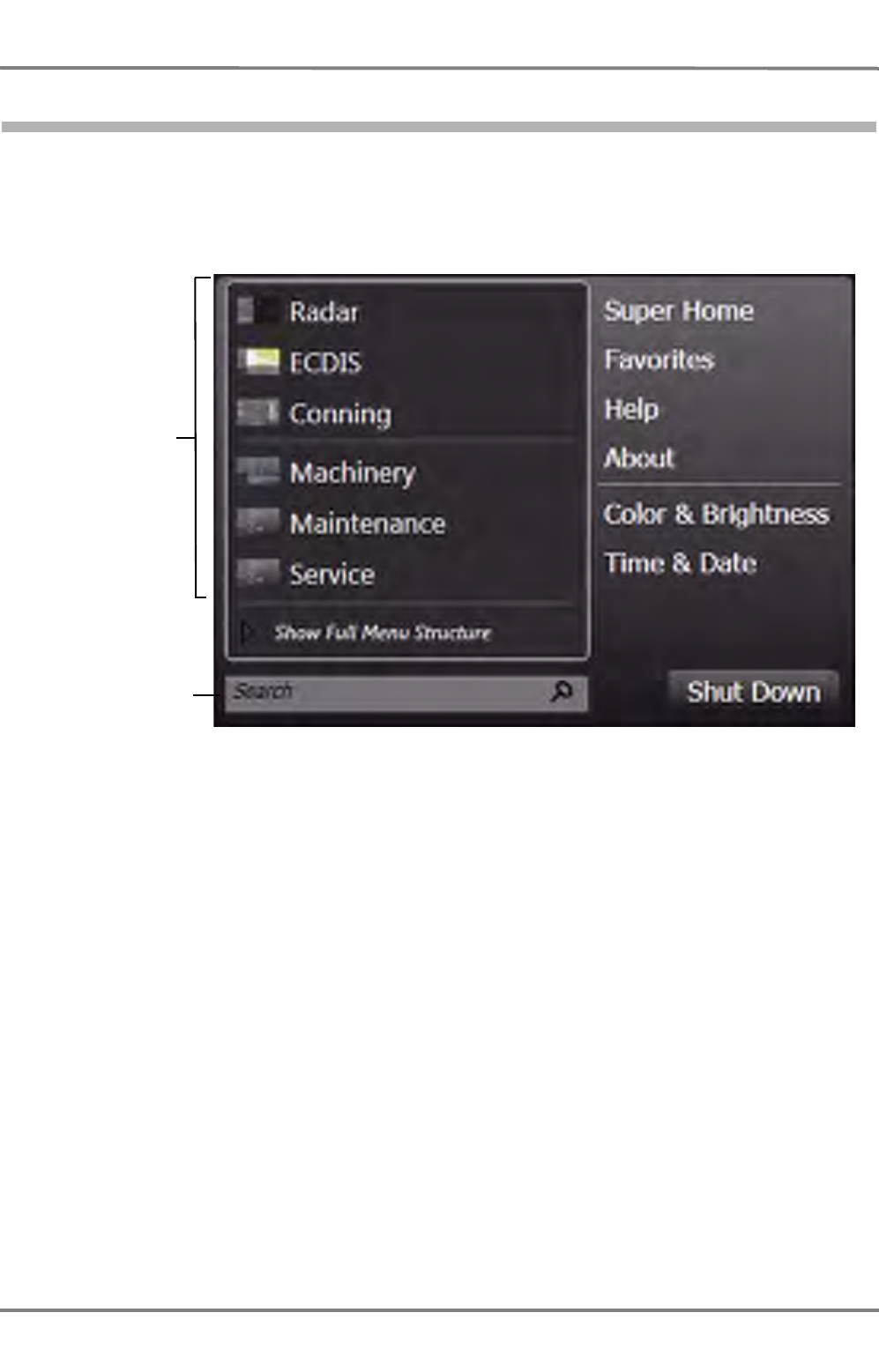
NACOS Platinum
ED 3100 G 140 / 04 (2011-11)
Operating Instructions
I-5 NACOS Platinum Graphical User Interface
I General.fm / 10.11.11
I-56
5.3.3 Menu Bar
The menu bar provides functions for navigation between applications and screens in the NACOS Plat-
inum. To open the menu, click on the Menu button in the bottom left corner of the display. The menu
resembles the Start menu of MS Windows 7. The figure below shows an example of a NACOS Platinum
menu which is displayed when clicking on the Menu button:
Fig. I / 21 Opened NACOS Platinum main menu
☞ When you move the mouse or trackball pointer over the buttons of the menu bar, you will experi-
ence a rollover effect indicating the button you are currently pointing at. This will help you to
pinpoint the right button for the current operating situation even in case of emergency.
Shortcuts to
the primary
applications
Search function
The individual buttons and elements are described below. See table I / 5.
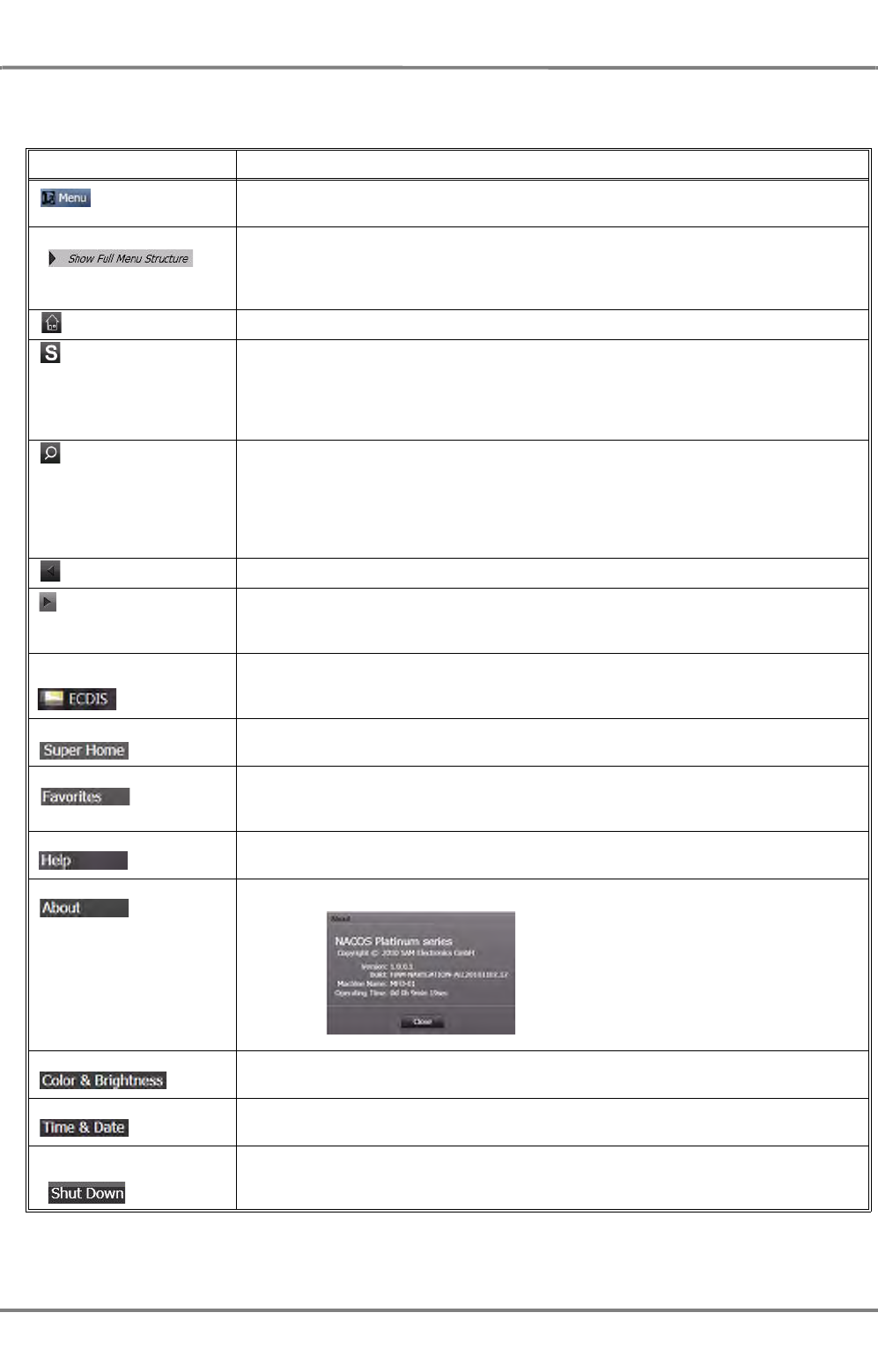
ED 3100 G 140 / 04 (2011-11)
Operating Instructions
I-5 NACOS Platinum Graphical User Interface
I General.fm / 10.11.11 I-57
NACOS Platinum
The items and functions of the menu bar depend on the configuration. They are described in the
following table:
Table I / 5 Items on the NACOS Platinum main menu
Menu Item / Button Explanation
When you click on the Menu button, the menu is opened like the Start menu
of MS Windows 7.
When the Show Full Menu Structure option is activated, the list will change
to a tree view showing a complete menu structure in form of a folder struc-
ture. The Option then becomes the Back option, and if you click on the Back
option, the menu returns to the standard variant.
Home The Home button takes you to the Super Home page.
S-mode The S-mode button takes you to a standard settings mode of the current
active application. S-mode for RADAR consists of a specific configuration of
settings according to the relevant standards for RADAR. S-mode is like a
clean-up function that brings the application to a default configuration closing
all manually opened expanders. See chapter II - 1 on page II-3 for details.
Search The Search button opens a text field and places the cursor in that search field
to do a system-wide search. When you start to type in the text or numbers
to be looked up, the menu switches into search result display mode. The
search results are instantly displayed and continuously updated as you type in
the character string.
☞
Full Screen The Full Screen button hides the sidebar. See chapter I - 5.3.3.1 on page 58.
Unhide Sidebar The Unhide Sidebar button restores the sidebar. Only displayed when the
current application is running in Full Screen mode. See chapter I - 5.3.3.1 on
page 58.
Shortcuts, e.g. Shortcuts access the configured main applications, e.g.: RADAR, ECDIS Moni-
toring, ECDIS Planning, and Machinery. There are also shortcuts provided that
access Super Home and the homepages of the main applications.
Super Home Returns to the Super Home window. See chapter 5.1 on page I-46 for
details.
Favorites Using the Favorites you can quickly select specific (favorite or often visited)
screens or application pages.
Help Nothing happens.
About Displays a window with information about the software version etc:
Color & Brightness Nothing happens.
Time & Date The menu window is closed.
Shut Down Use this button to shut down the MFD.
Observe the relevant safety notes! See chapter I - 4.4 on page 40
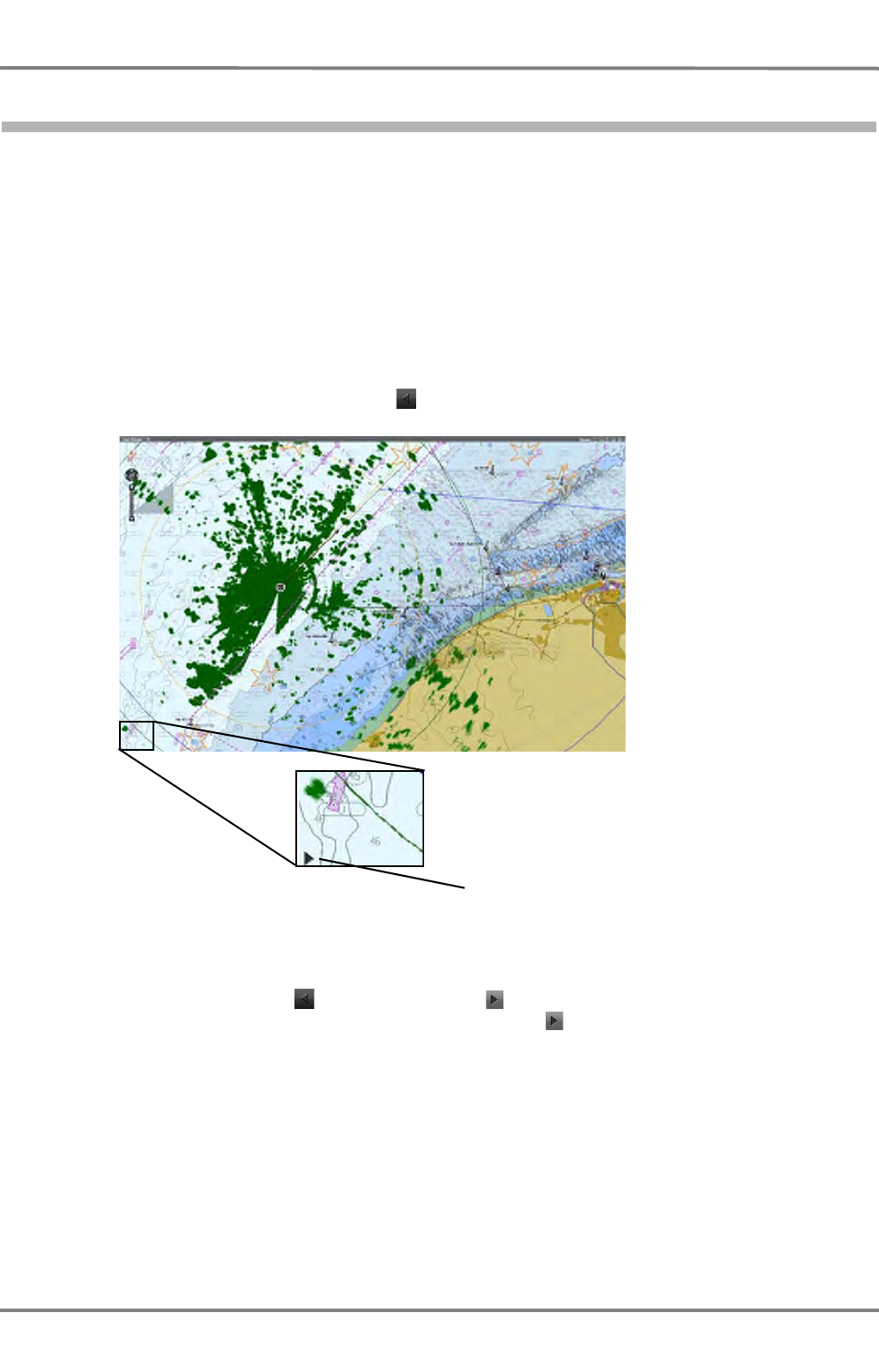
NACOS Platinum
ED 3100 G 140 / 04 (2011-11)
Operating Instructions
I-5 NACOS Platinum Graphical User Interface
I General.fm / 10.11.11
I-58
5.3.3.1 Full Screen Mode
The Full Screen (or hide sidebar) function is a mechanism that switches the display to a full screen view
that shows only the application area, and the sidebar is hidden. However, full screen mode is only avail-
able depending on the application:
- RADAR does not allow the full screen mode.
- ECDIS in monitoring mode does not allow the full screen mode.
- Operating the TRACKPILOT as the TRACKPILOT-Master does not allow the full screen mode.
- Machinery containing alarm displays does not allow the full screen mode.
- Conning allows the full screen mode.
To switch to full screen mode, click on the button (Full Screen) in the menu bar. The sidebar is then
hidden:
Fig. I / 22 ECDIS in full screen mode
In Full Screen mode, only the button becomes the button (Unhide sidebar). No other controls will
be visible. To unhide the sidebar again, simply click on the button in the bottom left corner. The
sidebar will then be restored.
Full screen button has become the
Unhide side bar button

ED 3100 G 140 / 04 (2011-11)
Operating Instructions
I-5 NACOS Platinum Graphical User Interface
I General.fm / 10.11.11 I-59
NACOS Platinum
5.4 Application Area
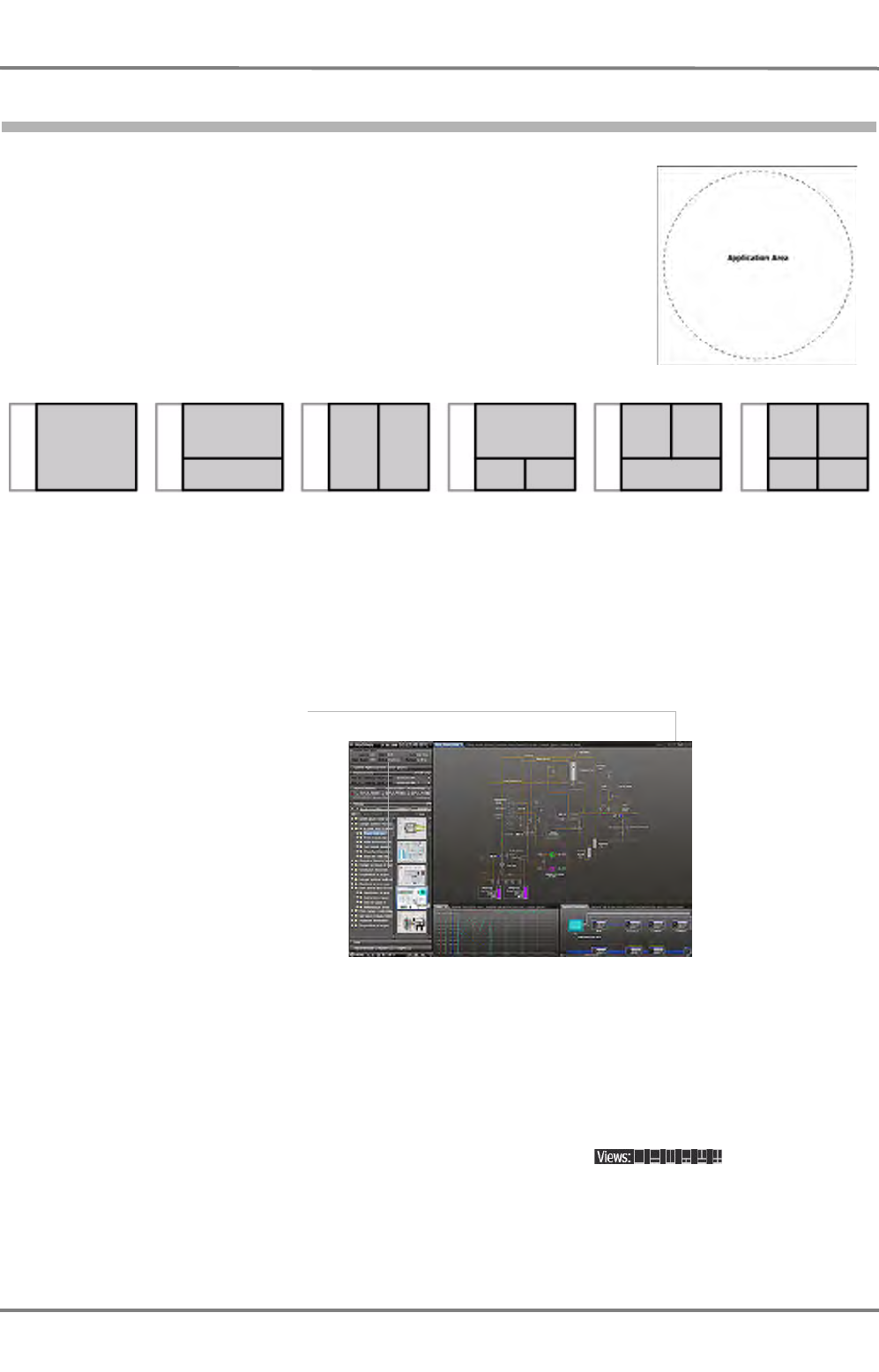
NACOS Platinum
ED 3100 G 140 / 04 (2011-11)
Operating Instructions
I-5 NACOS Platinum Graphical User Interface
I General.fm / 10.11.11
I-60
5.4.1 Application Area Frames
The application area on the right of the sidebar shows the main window
of the active application. It can show the RADAR PPI, the ECDIS chart,
or Machinery mimics etc. The application area can have six different
layout types. The grouped contents are arranged in separate frames.
Fig. I / 23 Application area frames
The sizes of the frames are flexible in some of the operation modes of the MFD. In some applications
the dividers between the frames can be moved to resize the frames, in others not. For that purpose,
click on the divider, hold the button and drag the divider into the desired direction. The picture below
shows an example of a screen with three frames:
Fig. I / 24 Example: Machinery screen with three frames
Each frame in a layout can contain multiple tabbed panels that group similar information. See chapter I
- 5.5 on page 62.
Switching Between Layouts
Layouts can be switched by selecting a new layout type using the buttons in the top
right corner of the screen. The currently selected layout is indicated by the white icon. The other layout
types are greyed out.
1
23
Layout Selector
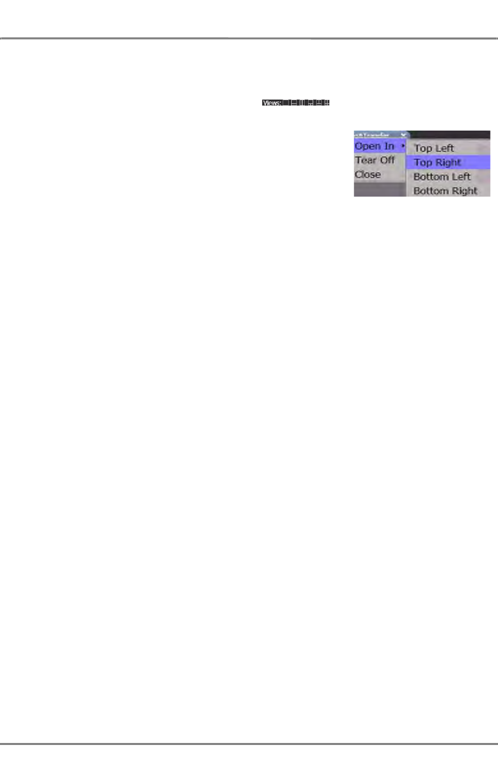
ED 3100 G 140 / 04 (2011-11)
Operating Instructions
I-5 NACOS Platinum Graphical User Interface
I General.fm / 10.11.11 I-61
NACOS Platinum
Switching to More Frames
When you switch to a layout type with more frames than the current layout, e.g. from 1 frame to 2
frames, the existing frames are kept and one or more new frames are added. The new tabs are loaded
with a default content. For that purpose, use the buttons in the title bar of the main
application window.
If the application area has multiple frames, then you can select a
specific frame, in which the tabbed panel will be opened, by pressing
the MORE key (right-clicking) on the tab and selecting the desired
option from the context menu. This behaviour is similar to the Open In
New Tab function in web browsers.
Switching to Different Arrangement of Frames
When you switch to an equal number of frames, e.g. from 2 horizontal to 2 vertical frames, some content
moves. No content is hidden if it is not necessary. Between the two-frames layouts the bottom content
moves to the right frame and vice versa. Between the three-frames layouts the top right content moves
to the bottom right frame and vice versa.
Switching to Less Frames
When you switch to a layout type with less frames than the current layout, e.g. from 3 frames to 2
frames, some frames will be hidden. In addition to choosing a new layout type using the buttons in the
top right corner of the screen, you can also switch to a lower layout type by closing the last tab in a
frame. When the last tab is closed the frame is closed too.
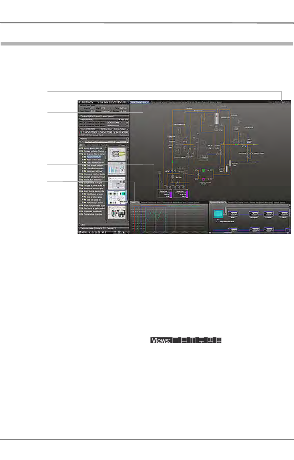
NACOS Platinum
ED 3100 G 140 / 04 (2011-11)
Operating Instructions
I-5 NACOS Platinum Graphical User Interface
I General.fm / 10.11.11
I-62
5.5 Tabbed Panels
In the NACOS Platinum applications, information are in many cases grouped on so-called tabbed panels.
Tabbed panels are screen pages which are arranged on top of each other like a pile of paper sheets.
The tabs identify the panels, and they are used to navigate through the panels. The picture below shows
an example:
Fig. I / 25 Example: Machinery screen with tabbed panels in three frames
The active tab is displayed in the foreground, and it is highlighted, which is e.g. indicated by a blue tab.
The active tabbed panel has the so-called focus. That means that editing, e.g. entering values or
adjusting the display, is only possible on that active tab. The other tabs are displayed as grey text sepa-
rated with a vertical line. When you click on a hidden tab in the background, it is brought to the fore-
ground and becomes the active tab. See table I / 25 above. You can also press [CTRL]+[TAB] on the
keyboard repeatedly to switch from tab to tab. In a multiple-frame-view, the other frames, which do not
have the focus, the front tabs are still highlighted by a grey tab but you will see that only one tab will
be active and have the focus.
Active Tab Behaviour when Switching to Different Layouts
When you switch to a new layout type using the buttons (Layout Selector)
the active tab has the following behaviour. If you switch to a layout type that has...
- One more frame: the new frame becomes the active frame.
- Two or three additional frames: the current active frame stays the active frame.
- The same number of frames: the current active frame moves along with the switching behaviour.
- Less frames: the current active frame remains the active frame unless it is the one which is closed.
In that case the horizontally adjacent frame becomes active.
In all cases the active tabbed panel will be highlighted, indicated by the blue tab.
Note:
Active Tab
Foremost Tab
Other Tabs
1
23
Layout Selector
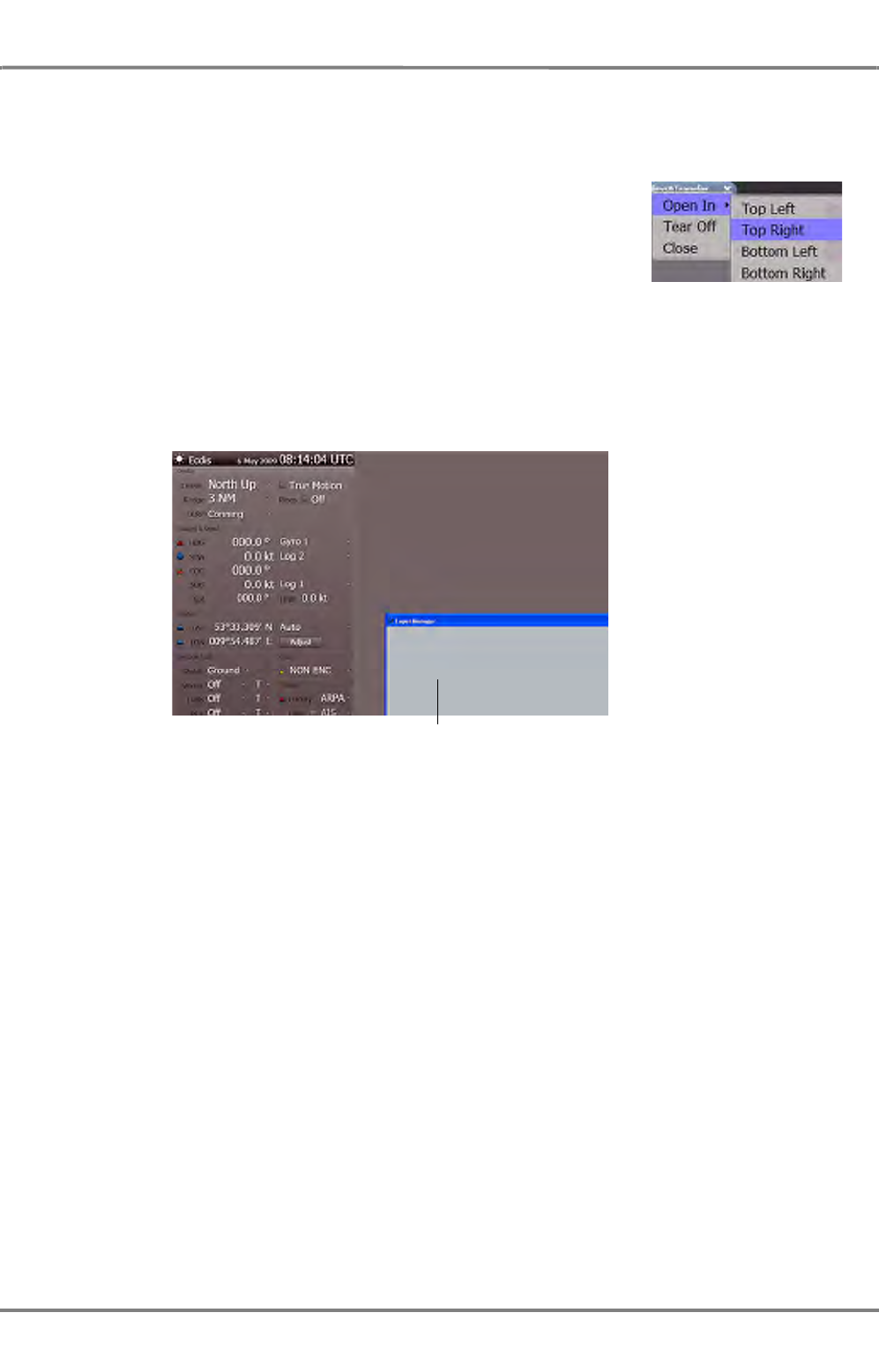
ED 3100 G 140 / 04 (2011-11)
Operating Instructions
I-5 NACOS Platinum Graphical User Interface
I General.fm / 10.11.11 I-63
NACOS Platinum
In some applications or display modes (e.g. radar) not all views may be available to the operator
Tab Context Menu
When you press the MORE key (right-click) on a tab, this will open the
context menu. Using a tab’s context menu you can specifically adjust
the tabbed panel’s appearance on screen and move it to a different
location on screen.
The following options are available:
- Open in
Displays the contents of the tab in a different frame, which you select in a sub-menu.
- Tear Off
Display the contents of the tab in a new, independent window that can be moved all over the
screen. To make the window a tab again, drag and drop the window by pointing at its upper left
corner and move it back to the tab’s position in the upper left corner of the respective frame.
Fig. I / 26 Tab after using tear-off function
- Close
Closes the current tabbed panel.
Torn-off tab
...now displayed as a window
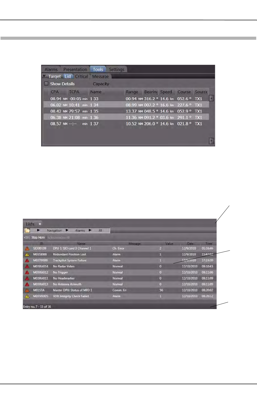
NACOS Platinum
ED 3100 G 140 / 04 (2011-11)
Operating Instructions
I-5 NACOS Platinum Graphical User Interface
I General.fm / 10.11.11
I-64
5.6 Lists & Tables
Wherever useful in NACOS Platinum, system data which have a record structure are displayed in lists,
e.g. alarms, track details, etc. In the following you will find examples of two lists.
Fig. I / 27 Example 1: Target List in RADAR sidebar
The target list shows the the currently tracked radar targets. Using the scrollbar on the right you can
scroll and page up and down the list. The next figure shows an example of the Machinery Alarm List:
Fig. I / 28 Example 2: Alarm List
Lists have a header, a details pane, and a footer.
Header
Details
pane
Footer

ED 3100 G 140 / 04 (2011-11)
Operating Instructions
I-5 NACOS Platinum Graphical User Interface
I General.fm / 10.11.11 I-65
NACOS Platinum
List Details Pane
In the top row of the details pane you will find the column headings. You can change
the sorting order by clicking on a column heading. The sorting order is indicated by
a small arrow. For example, the arrow up in the Name column indicates that the list
is sorted by the Name column in alphanumerically ascending order. When you click
on the Name column again, this will revert the sorting order to descending.
In some lists the sorting order is predefined. For example, the Alarm list must be sorted chronologically.
Hence it is predefined that the Alarm list is sorted by the time column in descending order starting with
the oldest alarm. The width of a column can be adjusted by dragging the separator line between two
column headings. In some cases adjusting of width may be disabled. Also showing, hiding and reordering
of columns can be enabled or restricted in the individual case.
List Footer
The footer of a list in some cases contains the number of list entries.

NACOS Platinum
ED 3100 G 140 / 04 (2011-11)
Operating Instructions
I-5 NACOS Platinum Graphical User Interface
I General.fm / 10.11.11
I-66
5.7 Dialogues
Dialogues are opened when you click on buttons or they are opened by the system as a response to
actions or events, e.g. in case of error. Message dialogues and popup edit windows need to be differen-
tiated, and they are explained in the following.
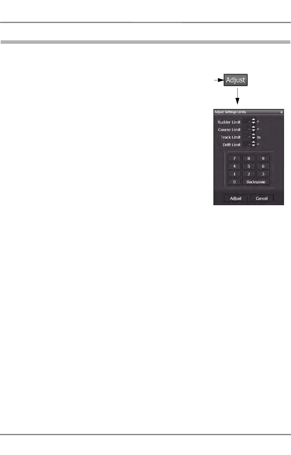
ED 3100 G 140 / 04 (2011-11)
Operating Instructions
I-5 NACOS Platinum Graphical User Interface
I General.fm / 10.11.11 I-67
NACOS Platinum
5.7.1 Popup Edit Windows
When you wish to adjust a value in the NACOS Platinum, you will in many cases click on an Adjust
button to open a separate popup edit window. Such a window contains:
- Edit fields with a label in front. The edit field will allow input
of text. Also, the small up-down arrows are provided that
increments/decrements the value. See chapter I - 5.9.8 on
page 77. In rare cases a slider might also be available.
- An indication of the range the value can have (for example
0 - 360°).
- OK button and a Cancel button. The OK preferably uses a
more specific verb that is applicable to the specific action,
like 'Adjust' or 'Send'.
Click
(Example)
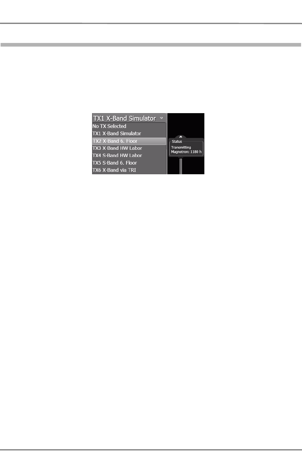
NACOS Platinum
ED 3100 G 140 / 04 (2011-11)
Operating Instructions
I-5 NACOS Platinum Graphical User Interface
I General.fm / 10.11.11
I-68
5.8 Tooltips
Tooltips are an interface element that is used to provide you with instant information on elements you
see on screen. Tooltips are small text pop-ups which are displayed when you simply point at elements
on screen. After a short delay, a small popup is displayed with a short description informing you about
the function or meaning of the element you pointed at. After a short while, the tooltip is faded out so
that you can see all screen information again.
When you open the menu and move the trackball pointer down the list of menu items, tooltips are
displayed for the individual menu items:
Fig. I / 29 Tooltip of a menu item
☞ Please note that you will not find tooltips on all elements on screen but on important display
elements and controls such as buttons and dropdown menus. Also, many screen objects like the
tools, chart symbols and targets in the PPI of the radar can have tooltips to supply relevant infor-
mation such as distance, bearing and ETA, or the own ship’s position.
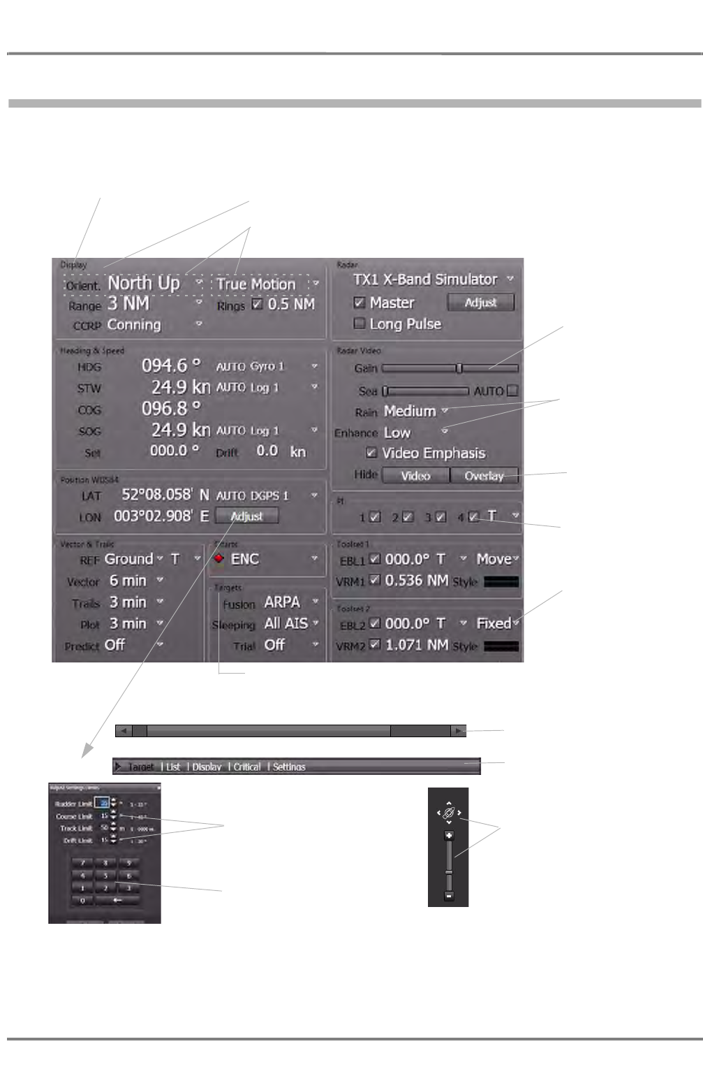
ED 3100 G 140 / 04 (2011-11)
Operating Instructions
I-5 NACOS Platinum Graphical User Interface
I General.fm / 10.11.11 I-69
NACOS Platinum
5.9 Controls – Adjusting Values
Most of the controls used in the NACOS Platinum applications are very similar to the known controls used
by Microsoft Windows. The picture below shows some examples of the controls:
Fig. I / 30 Examples of NACOS Platinum controls
The individual controls shown in the figure are described in the following sub-sections.
Check boxes
See chapter 5.9.6 on
page I-75.
Dropdown menu
See chapter 5.9.5 on
page I-74.
Slider
See chapter 5.9.3 on
page I-72.
Alarm/Warning icon related to the indication
See chapter 5.9.8 on page I-77.
Push button
See chapter 5.9.4 on
page I-73.
Field group, controls for the same topic
See chapter 5.9.2 on page I-71.
Field group name
Fields with
dropdown menus
Fields
See chapter 5.9.1 on page I-70.
Spin boxes
See chapter 5.9.8 on page I-77.
Zoom and pan control
See chapter 5.9.10 on page I-79.
Scrollbar
See chapter 5.9.7 on page I-76.
Expander
See chapter 5.9.10 on page I-79.
Keys for numeric values
See chapter 5.9.9 on page I-78.

NACOS Platinum
ED 3100 G 140 / 04 (2011-11)
Operating Instructions
I-5 NACOS Platinum Graphical User Interface
I General.fm / 10.11.11
I-70
5.9.1 Fields
In NACOS Platinum, values in form of text, numbers, slider settings, check boxes, etc. are generally
referred to as fields. A field consists of the value and a label, the field name. Some of the fields are read-
only, they only serve for information purposes. In other fields, the values can be adjusted. See chapter
I - 5.9 on page 69.

ED 3100 G 140 / 04 (2011-11)
Operating Instructions
I-5 NACOS Platinum Graphical User Interface
I General.fm / 10.11.11 I-71
NACOS Platinum
5.9.2 Field Groups
Field groups are represented on the NACOS Platinum user interface by a thin frame around a number of
fields. The frame indicates that the fields inside it belong together, i.e. that they belong to the same
subject or to a group of related items. Field groups have a name which is a kind of heading for the fields
inside the group.

NACOS Platinum
ED 3100 G 140 / 04 (2011-11)
Operating Instructions
I-5 NACOS Platinum Graphical User Interface
I General.fm / 10.11.11
I-72
5.9.3 Sliders
Using sliders you can set a value within a range of possible values. The
current value is indicated as you drag the slider to either side. The
minimum value is 0%, the maximum value is 100%. Simply clicking on
the slider’s handle displays the current value of the slider.
When you click on the slider next to the current value, this will increase
or decrease the value by 10 or another predefined value.
Show current value
Decrease value by 10

ED 3100 G 140 / 04 (2011-11)
Operating Instructions
I-5 NACOS Platinum Graphical User Interface
I General.fm / 10.11.11 I-73
NACOS Platinum
5.9.4 Push Buttons
Push buttons resemble buttons in the real world. When you press them, something will happen. When
you click on a push button on screen an action will be carried out or details will be displayed. The
purpose of a button is indicated by its label, in some cases tooltips are provided. See chapter I - 5.8 on
page 68.
☞ The Hide Video / Overlay buttons are spring-loaded. They are only
active as long as the appropriate button of the pointing device is
pressed.

NACOS Platinum
ED 3100 G 140 / 04 (2011-11)
Operating Instructions
I-5 NACOS Platinum Graphical User Interface
I General.fm / 10.11.11
I-74
5.9.5 Dropdown Menus
Dropdown menus are indicated by a small downward arrow next to a
field. To open the menu, click on the arrow. To select different value for
the field, click the desired item on the dropdown menu. The field is then
updated accordingly. To close the menu without making any changes,
just click on any free area on screen or press the [ESC] button on the
keyboard.

ED 3100 G 140 / 04 (2011-11)
Operating Instructions
I-5 NACOS Platinum Graphical User Interface
I General.fm / 10.11.11 I-75
NACOS Platinum
5.9.6 Check Boxes
Check boxes indicate that there is an option that can be set or not. In
the example in the figure on the right, the parallel index lines (PI) 1
to 4 are ticked off, i.e. selected and thus activated. This is indicated
by the small check mark . To select a check box, just click on it so
that it is ticked off. To clear the check box again, click on it so that
the check mark disappears ( ).

NACOS Platinum
ED 3100 G 140 / 04 (2011-11)
Operating Instructions
I-5 NACOS Platinum Graphical User Interface
I General.fm / 10.11.11
I-76
5.9.7 Scroll Bars
Scroll bars are displayed when contents do not fit on the screen or sidebar etc. You can then use scroll
bars to move the display up and down or sideways to view hidden parts.
To scroll the display in small steps you can click on the scroll arrows at the end of the scrollbar. To page
through the display in larger steps click on the scrollbar or drag the scroll box. Alternatively you can use
the navigation keys of the computer keyboard, e.g. arrow keys or [PAGE UP] and [Page DOWN] for
vertical scroll bars.

ED 3100 G 140 / 04 (2011-11)
Operating Instructions
I-5 NACOS Platinum Graphical User Interface
I General.fm / 10.11.11 I-77
NACOS Platinum
5.9.8 Spin boxes
Spin boxes are used in the NACOS Platinum to display and adjust
numeric values. To adjust the value you can enter the new value
directly in the text box. Alternatively, you can use the small arrow
buttons. When you click on the small arrows and hold the trackball button, then the velocity value in the
example will increase or decrease continuously until you release the button again. A single click on one
of the buttons will increase or decrease the value by one increment step.
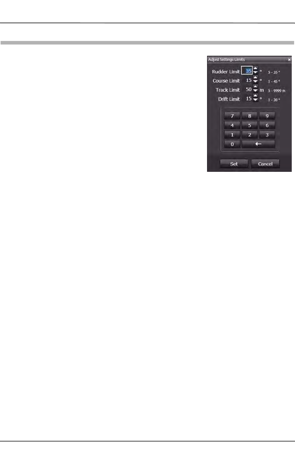
NACOS Platinum
ED 3100 G 140 / 04 (2011-11)
Operating Instructions
I-5 NACOS Platinum Graphical User Interface
I General.fm / 10.11.11
I-78
5.9.9 Keys for Numeric Values
Whenever it is possible or needed to enter a numeric value, the
appropriate keys wil be displayed in the control window. Select the
value to be changed and enter the desired value by clicking the
appropriate keys.
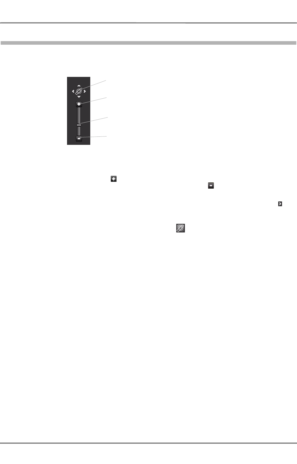
ED 3100 G 140 / 04 (2011-11)
Operating Instructions
I-5 NACOS Platinum Graphical User Interface
I General.fm / 10.11.11 I-79
NACOS Platinum
5.9.10 Zoom and Pan Control
The zoom and pan control in NACOS Platinum consists of a slider to adjust the zoom factor for, e.g., the
ECDIS chart, and the compass control with pan buttons, which you can use to move the image section
currently displayed.
Fig. I / 31 Zoom and pan control
To zoom in in increments, click on , you will then see more details on the respective display. However,
the overall area displayed is smaller. To zoom out again, click on the . You will then see less details
but you will have a better general overview of, e.g. an electronic chart displayed.
To pan the display, use the panning arrows of the compass control. For example, if you click on then
the display moves to the right in increments to view a different image section of a chart or whatever is
displayed. The effect is like travelling with the eye over a large map.
To center the display, e.g. after panning, just click on the icon once.
-
Compass control
with 4 pan arrows
Slider to adjust zoom
factor
Zoom in
Zoom out
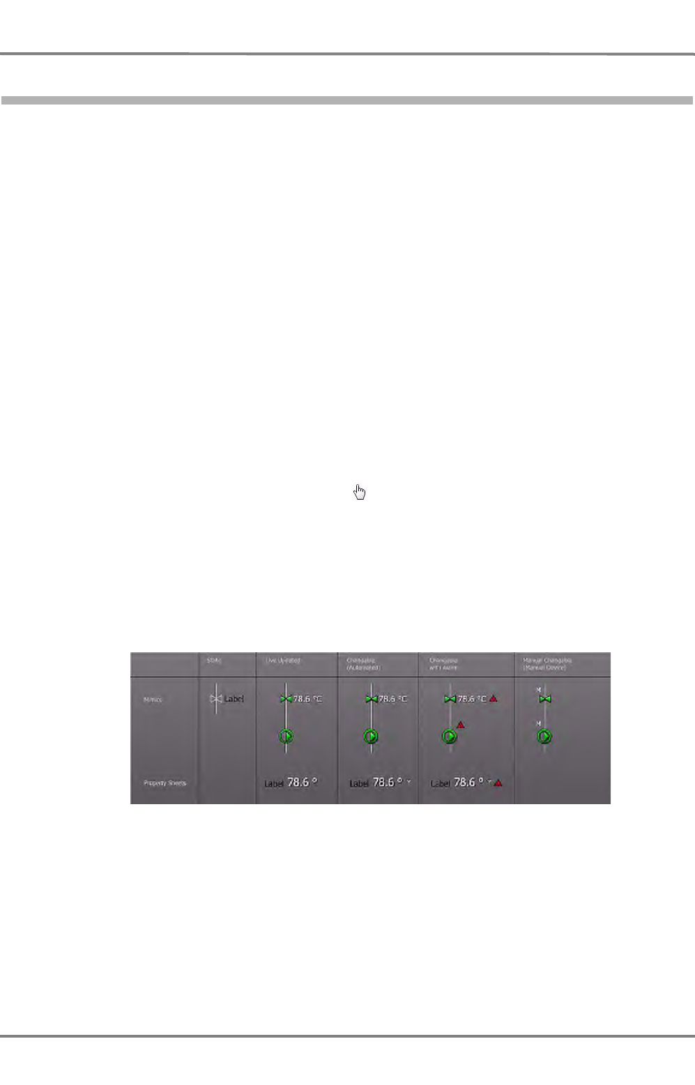
NACOS Platinum
ED 3100 G 140 / 04 (2011-11)
Operating Instructions
I-5 NACOS Platinum Graphical User Interface
I General.fm / 10.11.11
I-80
5.9.11 Alphanumeric and Graphical Indications
To make things stand out on mimics and on graphics presentations special kinds of indications are
provided. See figure I / 32. You will find the following four types of indicators:
- Static graphics and symbols
These are not operational. Neither manual nor automatic. They are visualized to help you getting
an idea of the real infrastructure aboard, e.g. of piping systems. The status is not shown because
the device is not connected to any sensoring or to the interface.
- Live updated graphics and values
These graphics are not operated through the NACOS Platinum user interface, but the state and value
is automatically (live) updated by the system. These graphics are indicated with a drop shadow and
colored graphics or a value / text indicating their state (usually "running" or "stopped"). The drop
shadow indicates live updating by the system. The color of the graphics is used to indicate the state
of the related machinery component. Even if it is blocked for some reason the color shall be main-
tained as long as the state is known. For Machinery components the block state is indicated by a
"B" shown next to the graphics.
- Changeable (clickable) graphics and values
These graphics can be operated using the NACOS Platinum user interface. They are clickable and
can be set or changed, and the value is automatically (live) updated via the system. These values
are indicated with a drop shadow below the colored graphic or value. The color of the graphic is
used to indicate the state of the related machinery component. For Machinery components the block
state is indicated by a "B" shown next to the graphics. When the mouse pointer is over the object
the pointer also changes to a pointing hand .
- Manually changeable graphics and values
This is an infrequent indicator. The state of a device can be set in the interface but the device is
not operated from the interface. Also the value is not live updated via the system. You have to go
to the physical device and change the state. The indication on the screen is an aid to the human
memory. However it also has the danger of indicating a different state than the device is actually
in. These indicators will be visualized with a "manual" icon. The colored graphic will display the
state.
Fig. I / 32 Visualisation types of indication
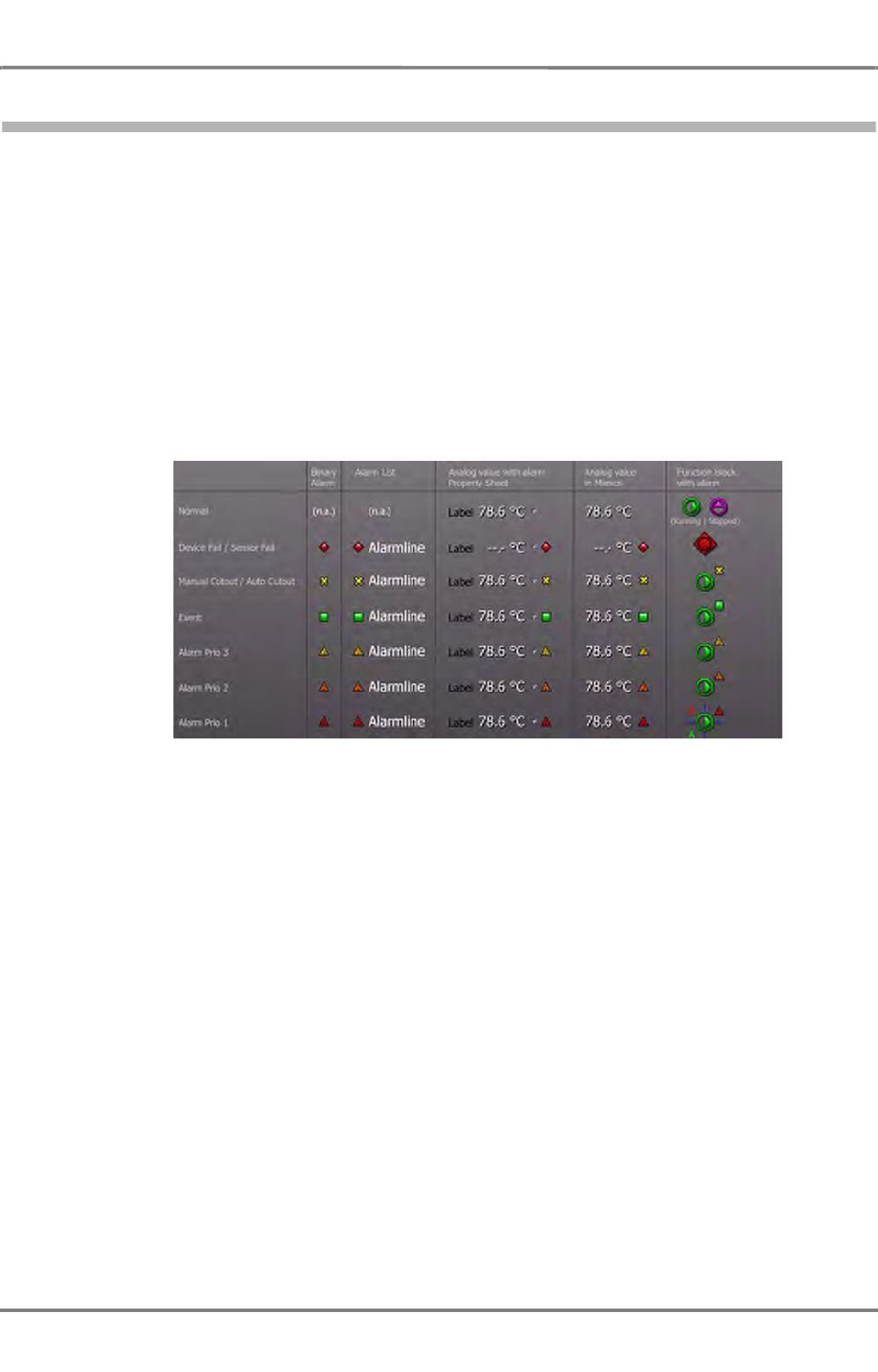
ED 3100 G 140 / 04 (2011-11)
Operating Instructions
I-5 NACOS Platinum Graphical User Interface
I General.fm / 10.11.11 I-81
NACOS Platinum
5.9.12 Alarm Icons
In NACOS Platinum all alarms will be indicated in the same way in all cases. The different states of an
alarm are indicated by different symbols in dedicated colors. The symbols will be used in the following
manner:
- Placed in front of the alarm line in Alarm Lists
- Placed in front of the label in the permanent area of RADAR and ECDIS
- As a separate symbol in mimic diagrams for binary alarms. (e.g. used for a level switch in a tank)
- As a symbol placed behind the Unit of an analogue value displayed on a mimic diagram. (e.g. used
for display of a temperature with a limit)
- As a symbol placed beside a function block symbol (indicating the state of machinery components,
e.g. pumps, valves, generators etc.
Fig. I / 33 Example of alarm types
For detailed information about alarms, please refer to the
V-ALARMS
part of these operating instructions.
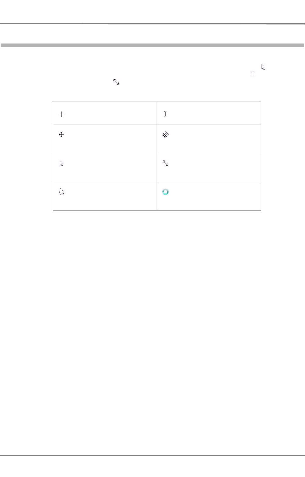
NACOS Platinum
ED 3100 G 140 / 04 (2011-11)
Operating Instructions
I-5 NACOS Platinum Graphical User Interface
I General.fm / 10.11.11
I-82
5.10 Mouse Pointers and Clicks
In NACOS Platinum you will experience that the shape of the mouse or trackball pointer will change in
different situations as you move it over the screen. The basic shape is always the arrow used to open
menus and options on screen. In text fields, the pointer becomes a text edit caret ; on dividers, the
pointer turns into a double arrow indicating that you can resize something, and so on.
Table I / 6 Mouse pointers
The different shapes are explained in the following for the RADAR and ECDIS applications as well as for
the Machinery application. The possible types of clicks are explained separately. See chapter I - on page
31.
Precision select Text edit caret (cursor)
Cross hair Move
Arrow Resize, double arrow
Pointing hand Waiting
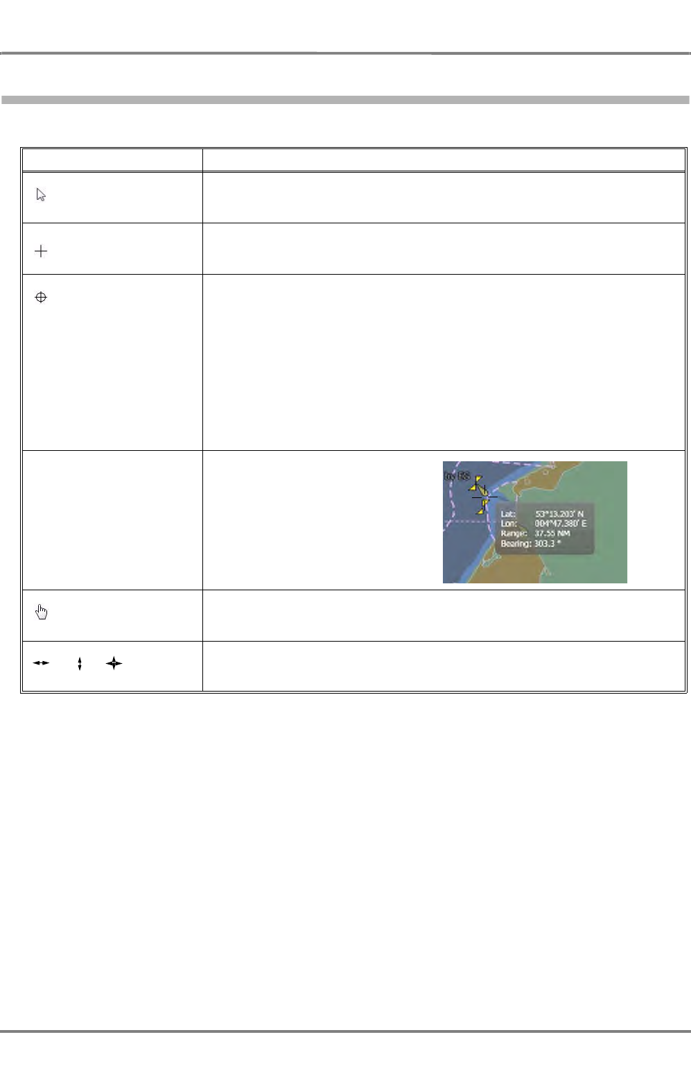
ED 3100 G 140 / 04 (2011-11)
Operating Instructions
I-5 NACOS Platinum Graphical User Interface
I General.fm / 10.11.11 I-83
NACOS Platinum
5.10.1 Pointers in RADAR and ECDIS
You will find the following specific types of pointers in the RADAR and ECDIS applications:
Table I / 7 RADAR and ECDIS pointers
Pointer Explanation
Arrow Standard pointer when you are not pointing at an any specific object on
screen in the application area but when you point at menus, fields and
other controls in the sidebar, in dialogues, or in frames showing lists etc.
Precision select Standard pointer when you are not pointing at an any specific object on
screen in the application area.
Cross hair Cross hair– one target:
When the mouse pointer is over one target, the cross hair pointer indicates
that the target can be acquired. A single left click acquires the target.
cross hair – multiple targets:
When the mouse pointer is over multiple targets, the cross hair pointer indi-
cates that the targets can be acquired. A single left click opens a menu that
displays the relevant acquisition options (for instance Acquire RADAR,
Acquire AIS, Acquire Both, Escape)
When the mouse pointer is over an acquired target a box around the target
indicates that it is already acquired and properties / data of the target can
be accessed. A single right click displays the properties in a tooltip or
popup. This popup should automatically hide after a few seconds.
Position indication When you move the pointer
over the RADAR PPI or the
ECDIS display, then the
respective position is indicated
in a text box together with
range and bearing.
Pointing hand When the mouse pointer is over a clickable object, the pointing hand indi-
cates that the object is clickable. Both left and right clicks can have an
effect.
, , When the mouse pointer is over a moveable object, for example a "handle"
of a variable range marker, the arrows indicate the direction in which the
handle of the object can be moved.

NACOS Platinum
ED 3100 G 140 / 04 (2011-11)
Operating Instructions
I-5 NACOS Platinum Graphical User Interface
I General.fm / 10.11.11
I-84
5.10.2 Mouse Pointers for Machinery
You will find the following specific types of pointers in the Machinery application:
Table I / 8 Machinery pointers
Pointer Explanation
Arrow Standard pointer when you are not pointing at an any specific object on
screen in the application area but when you point at menus, fields and
other controls in the sidebar, in dialogues, or in frames showing lists etc.
Pointing hand When the mouse pointer is over a clickable object, the pointing hand indi-
cates that the object is clickable. Both left and right clicks can have an
effect.

QUICK START GUIDE


ED 3100 G 140 / 04 (2011-11)
Operating Instructions
II-1 How to start quickly
II Quick Start Guide.fm / 10.11.11 II-3
NACOS Platinum
1 How to start quickly
After power-on, the system starts automatically and displays the Super Home page. See 5 on page I-
45. From this page, the appropriate functions of the system can be chosen.
Since the electronic units are always in standby, even if the screens are dark, it is neccessary to be able
to return to a specified state, the power - on state.
For this, the S-Mode is relevant.
Once the appropriate button is clicked on the screen, the RADAR/ECDIS returns to the settings that have
been present on power-on.

NACOS Platinum
ED 3100 G 140 / 04 (2011-11)
Operating Instructions
II-1 How to start quickly
II Quick Start Guide.fm / 10.11.11
II-4
1.1 The S-Mode for RADAR
Pressing the S-Mode button for RADAR leads the following settings:
- Range: 6 nm
- Orientation: North up
- VRM1 on
- EBL1 on
- Vectors & plots: on, 6 minutes
- Transceiver settings remain unchanged
- Target acquisition status remains unchanged
- Route remains visible (if activated)
- ENC: if available and active, the display will be reduced to “Base Display”
- Color-scheme / brightness control remains unchanged.
- expanders are closed apart from the target list

ED 3100 G 140 / 04 (2011-11)
Operating Instructions
II-1 How to start quickly
II Quick Start Guide.fm / 10.11.11 II-5
NACOS Platinum
1.2 The S-Mode for ECDIS
Pressing the S-Mode button for ECDIS leads the following settings:

NACOS Platinum
ED 3100 G 140 / 04 (2011-11)
Operating Instructions
II-1 How to start quickly
II Quick Start Guide.fm / 10.11.11
II-6

MAIN APPLICATIONS


ED 3100 G 140 / 04 (2011-11)
Operating Instructions
III-1 Overview of Products and Applications
III Main Applications.fm / 10.11.11 III-3
NACOS Platinum
1 Overview of Products and Applications

NACOS Platinum
ED 3100 G 140 / 04 (2011-11)
Operating Instructions
III-1 Overview of Products and Applications
III Main Applications.fm / 10.11.11
III-4
1.1 NACOS Platinum Products
The NACOS Platinum Series is offering four advanced products for various vessel and user requirements
as follows:
Table III / 1 NACOS Platinum and its Applications
Each product provides one or more applications and possible options as indicated above. Each product
comprises also the necessary hardware to run these applications. The hardware consists of the Multi-
Functional-Display (workstation), navigation and engine interface, and in case of MACHINERY also auto-
mation I/O and controllers, and in case of RADAR also an X- or S-band antenna unit. The applications
come along with supporting packages for service, training, configuration, and others. The product name
as above is written at the top left frame corner of the monitor of the corresponding workstation (not the
screen!).
Each navigation product can be combined with the optional TRACKPILOT application. In that case the
keyboard of the corresponding workstation is fitted with the joystick and labelled with TRACKPILOT. On
the Platinum home page the additional TRACKPILOT application will be shown.
Further on the hardware is extended by an extra electronic unit as well as a special TRACKPILOT inter-
face. The TRACKPILOT application does not have its own user interface but is integrated in the non-
permanent area of RADAR or ECDIS.
ECDISPILOT and MULTIPILOT can be combined with the optional MACHINERY application. In that case
the Platinum home page shows the MACHINERY application in addition and the workstation is connected
via network to the automation subsystems.
Applications
Product RADAR CONNING ECDIS MACHINERY
RADARPILOT Option:
Advanced Option:
Chartradar
ECDISPILOT Option:
Advanced Option:
Automation
MULTIPILOT Option:
Advanced Option:
Automation
MCS
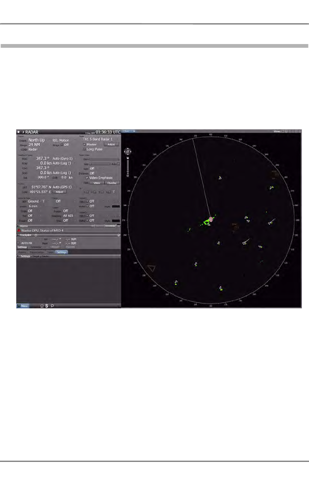
ED 3100 G 140 / 04 (2011-11)
Operating Instructions
III-1 Overview of Products and Applications
III Main Applications.fm / 10.11.11 III-5
NACOS Platinum
1.2 RADAR Application
The RADAR application shows the raw video as well as the radar targets processed by the antenna unit
which has been selected by the operator. The new IP RADAR technology allows the operator to switch
via network to any assigned antenna unit on-board (one or more X-band as well as one or more S-band
units). Advanced filter techniques are used for clutter supression and enhanced small target detection.
Various navigation tools are available for collision detection and calculation based on the pre-processed
targets. AIS targets from a separate AIS transponder unit are processed exactly in the same way as radar
targets. RADAR and AIS targets can be merged together. The user may edit his own user symbols and
route data on a separate layer under the radar presentation.
Fig. III / 1 Overview of the RADAR Screen
The "Advanced RADAR" option provides next to other features a CONNING application. The user may
switch over to this application at any time or have a separate display for permanent use.
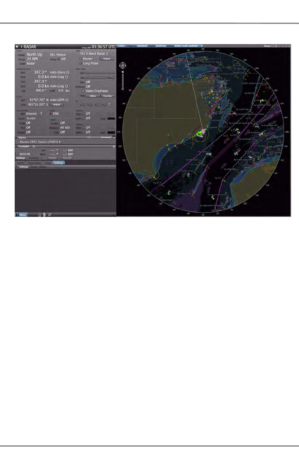
NACOS Platinum
ED 3100 G 140 / 04 (2011-11)
Operating Instructions
III-1 Overview of Products and Applications
III Main Applications.fm / 10.11.11
III-6
Fig. III / 2 Overview of the Chartradar Screen
The "Chartradar" option provides an ECDIS background within the bearing scale on the PPI. Chart data
bases for ENC are used. The Chartradar is approved as ECDIS back-up and designed to meet the IEC
62288 and IEC 62388, a standard for radar with chart.
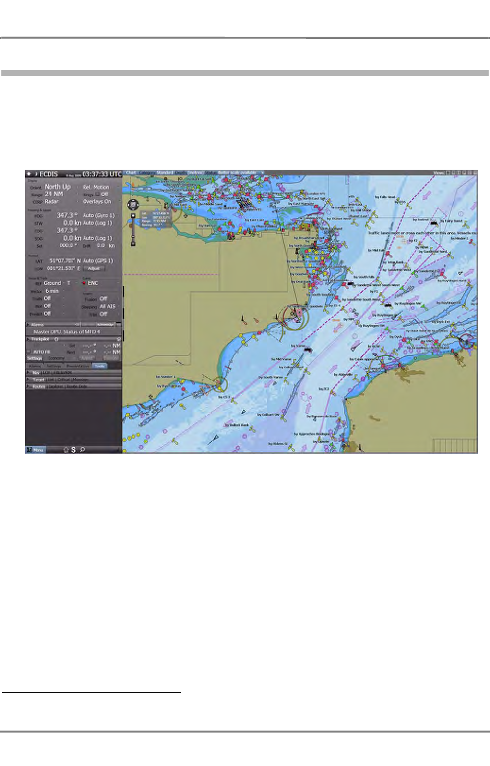
ED 3100 G 140 / 04 (2011-11)
Operating Instructions
III-1 Overview of Products and Applications
III Main Applications.fm / 10.11.11 III-7
NACOS Platinum
1.3 ECDIS Application
The ECDIS application for the ECDISPILOT as well as CHARTRADAR and MULTIPILOT presents the own
ship embedded in an ENC chart. Various tools are available for route planning and voyage execution, for
navigation, for route checking, for shallow water warning and for collision avoidance. AIS targets from a
separate AIS transponder unit and radar targets are processed together and merged in the same way as
for the RADAR application. 1)
Fig. III / 3 Overview of the ECDIS Screen
1) A Standalone-ECDISPILOT does not process RADAR targets.
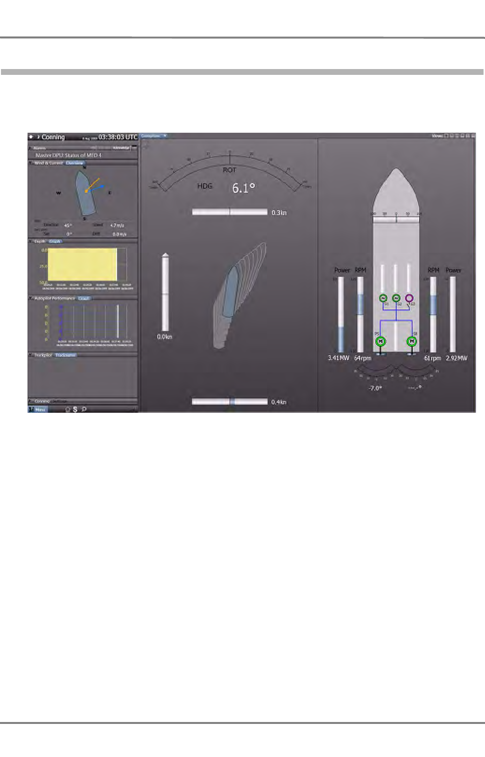
NACOS Platinum
ED 3100 G 140 / 04 (2011-11)
Operating Instructions
III-1 Overview of Products and Applications
III Main Applications.fm / 10.11.11
III-8
1.4 CONNING Application
The CONNING application provides an overview of the navigational situation of the vessel. It displays all
navigation data and if fitted with the optional engine interface also rudder and propulsion related data.
Fig. III / 4 Overview of the Conning Screen
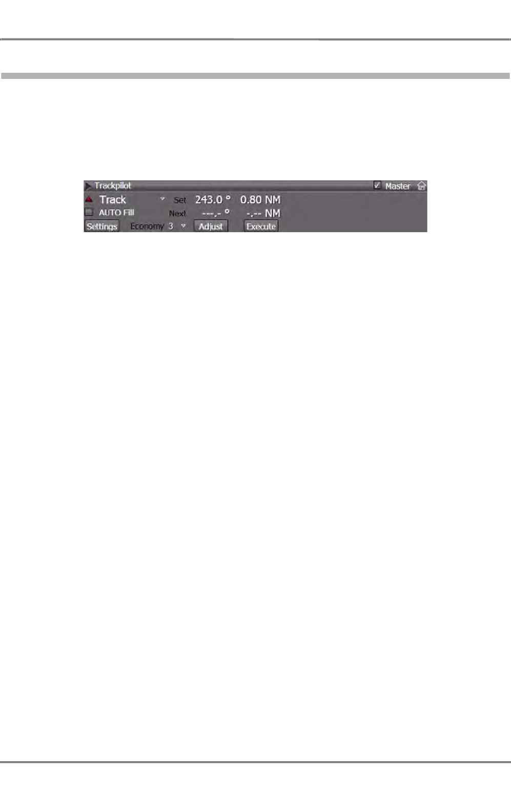
ED 3100 G 140 / 04 (2011-11)
Operating Instructions
III-1 Overview of Products and Applications
III Main Applications.fm / 10.11.11 III-9
NACOS Platinum
1.5 TRACKPILOT Application
The TRACKPILOT application controls the vessel for constant heading, course or along a pre-planned
track as prepared with the ECDIS planning function. With the option SPEEDPILOT the speed of the vessel
along a leg can be controlled to reach the final destination at a pre-planned time.
Fig. III / 5 Overview of the Trackpilot Expander
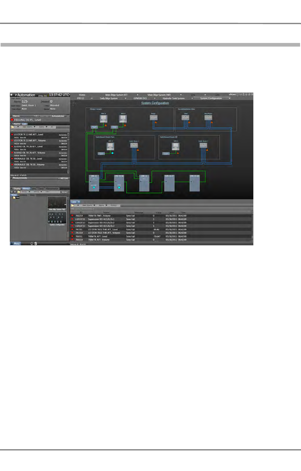
NACOS Platinum
ED 3100 G 140 / 04 (2011-11)
Operating Instructions
III-1 Overview of Products and Applications
III Main Applications.fm / 10.11.11
III-10
1.6 MACHINERY Application
The MACHINERY application provides remote indicators and controls for the complete automation system
on-board. Subsystems may include main engine control, fuel supply, cooling, generators, fire detection,
electric power distribution, ballast, etc.
Fig. III / 6 Overview of the Machinery Screen

ED 3100 G 140 / 04 (2011-11)
Operating Instructions
III-1 Overview of Products and Applications
III Main Applications.fm / 10.11.11 III-11
NACOS Platinum
1.7 Common Functions for Products and Applications
The table below gives an overview about the common NACOS Platinum functions which are used in the
RADAR and ECDIS applications and which can form a RADARPILOT, a CHARTRADAR, an ECDISPILOT,
or a MULTIPILOT. The main differences between these products are as follows:
- RADARPILOT: Basic radar functions incl. ARPA and AIS targets, no chart functions
- CHARTRADAR: As above, plus chart functions with black background colour table*
- ECDISPILOT: Chart functions in full colour, AIS targets on top
- MULTIPILOT: CHARTRADAR plus ECDIS with ARPA and AIS targets 1)
Fig. III / 7 Common Functions for Products and Applications
Function tested against Task RADAR
PILOT CHART
RADAR ECDIS MULTI
PILOT
Navigation sensor
management IEC 61162
IEC 62388/ Ch13 plot own ship with
vectors/ trails EEEE
Stabilize display IEC 62388/ Ch9 display traffic
scenario, HU, north EEEE
Navigation tools IEC 62388/ Ch8 provide EBL, VRM,
(and LOPs)* EEEE
Process radar video IEC 62388 / Ch 5,6 display raw radar
video EEEE
Target handling IEC 62388/ Ch10 display ARPA and AIS
targets EEEE
Display chart objects IEC 62388/ Ch11 display
buoys,beacons, etc. EEE
Display basic chart
areas IEC 61174 display land and water
areas EEE
Display user symbols
(maps) IEC 62388/ Ch 8 display user setbea-
cons, lines, etc. EEEE
CCRS IEC 62388/ Ch7 relate all nav. data to
single ref. point EEEE
Alarm management IEC 62388/ Ch15 process alarms on 3
levels EEEE
Route planning IEC 61174 provide waypoint
editor with control EEEE
Chart monitoring IEC 61174 check passage against
chart depth EEE
Chart maintenance IEC 61174 update chart informa-
tion EEE
Conning IEC 62288 show navigation
instruments EEEE
Track control IEC 62065 controls ship on pre-
planned route EEEE
Workstation hard-
ware IEC 60945 monitor; operating
device; processor EEEE
1) The detailed arrangement of foreground and background layers is shown on the following page

NACOS Platinum
ED 3100 G 140 / 04 (2011-11)
Operating Instructions
III-1 Overview of Products and Applications
III Main Applications.fm / 10.11.11
III-12
The table on the next page presents the most important layers and their priority shown for the
CHARTRADAR.
The arrangement for the MULTIPILOT is only slightly different. The priority of the radar video is changed
in favour of the chart objects. The radar video layer is shifted down and placed in between basic chart
areas and chart objects acc. to IEC 61174 (see arrow 1). The dusk and night colour sets used for the
chart areas are extended to the full daylight colour set. All other functions are the same.
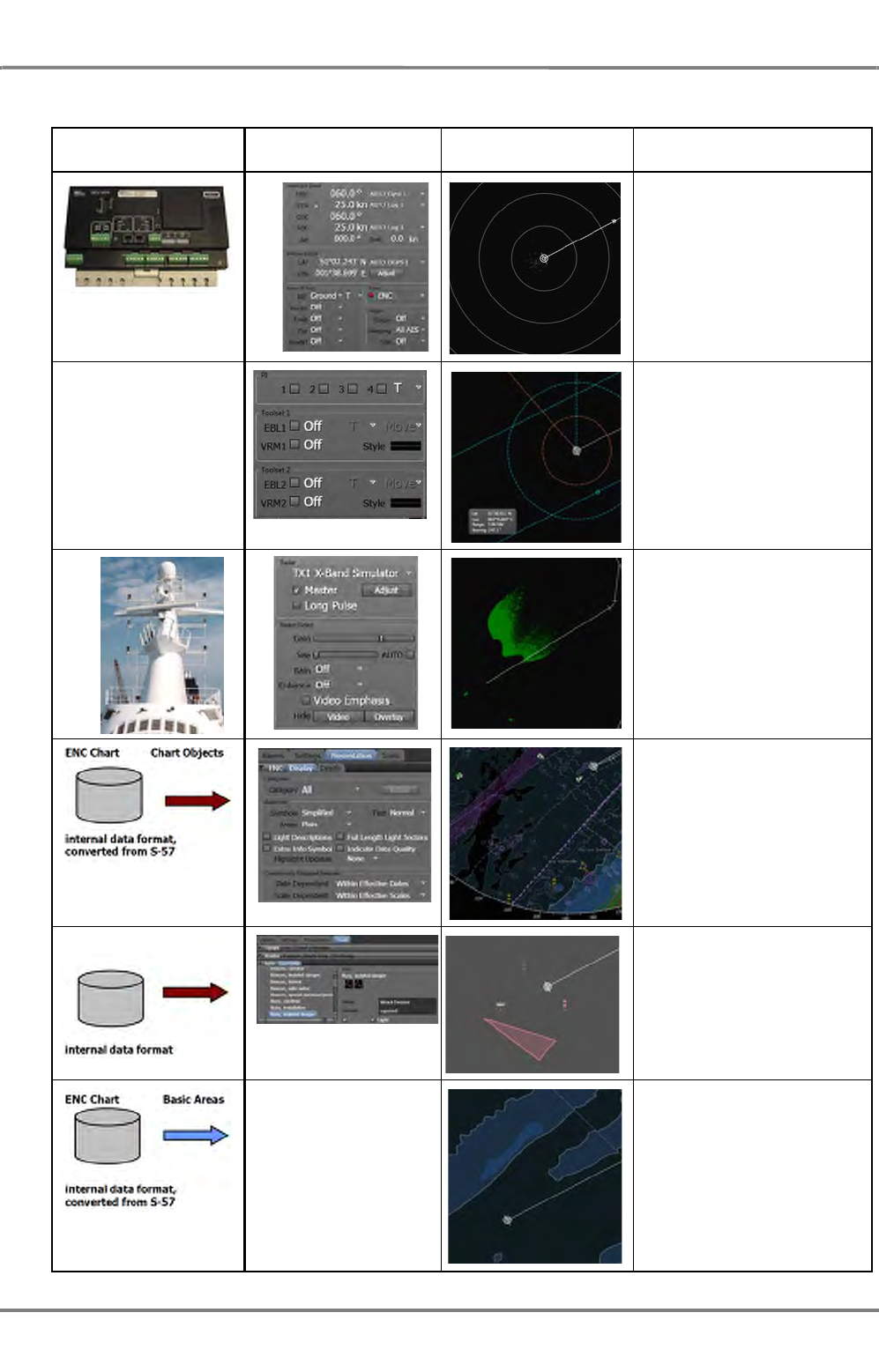
ED 3100 G 140 / 04 (2011-11)
Operating Instructions
III-1 Overview of Products and Applications
III Main Applications.fm / 10.11.11 III-13
NACOS Platinum
Data Source Function Controls Presentation Layer Objects and Priority
(for CHARTRADAR)
From navigation sensors
Own Ship (on top),
with headmarker, vector and
trails, AIS and ARPA targets
none Navigation Tools,
comprising EBL, VRM and LOP
RADAR Video,
raw video as received from
antenna unit, sea and rain
filtererd as selected by the
user
Chart Objects
buyos, beacons, traffic sepear-
ation, text labels, dangerous
zones, coastlines, planned
route
User symbols,
user defined buoys, beacons,
lines and areas
Basic Chart Area,
land, water, depth lines

NACOS Platinum
ED 3100 G 140 / 04 (2011-11)
Operating Instructions
III-1 Overview of Products and Applications
III Main Applications.fm / 10.11.11
III-14
The arrangement of layers is shown for the CHARTRADAR from top to bottom. For the MULTIPILOT the
raw video is shifted down as indicated by the arrow 1).
All the common functions as listed earlier and the layers as listed in the previous table are integrated to
a complete application for RADAR or for ECDIS.
If the two applications RADAR or ECDIS are combined on a single workstation to build-up a CHAR-
TRADAR or MULTIPILOT only those functions are added, which are not already available with the first
application. Each of the functions as listed above is only started once on a workstation. But depending
on the actual configuration it may have a slightly different appearance. Differences are listed i.e. at the
end of the Chartradar chapter.
Some common functions have been extracted from the description of the individual applications and set
in front of the RADAR and ECDIS description.
Examples are the Consistent Common Reference System (CCRS) (See chapter III - 2.1 on page III- 14),
the navigation sensor management, and the common user interface (HMI) (See chapter I - 5 on page I-
45).
More complex and more seldom used common functions have been extracted as well and set behind the
RADAR and ECDIS description.
Examples are the alarm management (See chapter V - 2 on page V-9), the route and chart monitoring
(See chapter C - 2 on page C-37), and the optional conning and track control function.
Please refer to the corresponding subsequent chapters for more detailed information.

ED 3100 G 140 / 04 (2011-11)
Operating Instructions
III-2 Common Functions for Navigation
III Main Applications.fm / 10.11.11 III-15
NACOS Platinum
2 Common Functions for Navigation

NACOS Platinum
ED 3100 G 140 / 04 (2011-11)
Operating Instructions
III-2 Common Functions for Navigation
III Main Applications.fm / 10.11.11
III-16
2.1 The Consistent Common Reference System (CCRS)
The NACOS Platinum navigation system is designed as a Consistent Common Reference System (CCRS).
It references all horizontal measurements such as target range, bearing, relative course, relative speed,
closest point of approach (CPA) or time to closest point of approach (TCPA) to one single point on-board,
the Consistent Common Reference Point (CCRP), typically the conning position of the bridge.
The offset between the installation location of a navigation sensor i.e. for position, speed, or heading
and the CCRP is compensated by the Platinum system. The offset between a radar antenna position and
the CCRP is compensated as well. If multiple antennas are installed, there is a provision for applying
different position offsets for each antenna in the radar system. The offsets are applied automatically
when any radar sensor is selected.
The CCRP can be selected by the user, the default setting is the conning position. For precise radar
measurements it can be set to the just selected radar antenna. The relations are shown in the following
two diagrams.
Fig. III / 8 CCRP on RADAR
Measurement relative to the Conning
Position. (CCRP = Conning)
All bearings, distances, positions are indi-
cated relative to the conning position on the
ship´s bridge
Measurement relative to the RADAR
antenna (Bow RADAR as an example)
(CCRP = RADAR)
All bearings, distances, position etc are
indicated as seen from the radar antenna
location.
All different radar antennas on the ship
can be selected as the reference for the
radar CCRP.
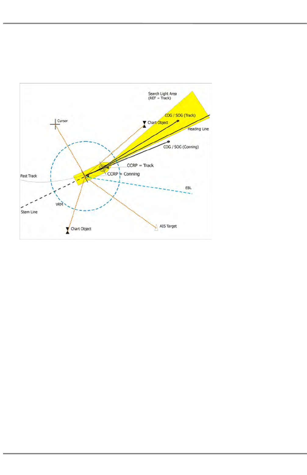
ED 3100 G 140 / 04 (2011-11)
Operating Instructions
III-2 Common Functions for Navigation
III Main Applications.fm / 10.11.11 III-17
NACOS Platinum
For systems with integrated Track Control System (Autopilot) it is important to use the same reference
position for the track control and for the monitoring process of the ECDIS. For both purposes the so-
called System Position, located in the bow of the ship, is used system-wide.
In NACOS Platinum the System Position is called Track Control position, which can be selected with
CCRP = Track in the GUI as an optional reference point.
Fig. III / 9 CCRP on ECDIS
For measurements relative to the own ship (EBL, VRM, Cursor, target data) on the NACOS Platinum the
Conning Position is used normally. In contrast to a RADAR system, where the reference may also be the
position of the radar antenna, in a stand-alone ECDIS no alternative reference position than the Track
Control position can be selected by the operator.
Measurements relative to
the Conning Position
(CCRP = Conning)
The chart monitoring func-
tion of the ECDIS sub-
system is done for the
CCRP=Track Control Posi-
tion, i.e. the guard sector
(also called look-ahead
sector) starts at the bow of
the ship. Length and width
of the sector can be
adjusted in the ECDIS-HMI.

NACOS Platinum
ED 3100 G 140 / 04 (2011-11)
Operating Instructions
III-2 Common Functions for Navigation
III Main Applications.fm / 10.11.11
III-18
2.2 Context Menus
Context Menus in the Application Area
Context menus are available in the application area, i.e. the PPI in RADAR mode and the Chart Area in
ECDIS mode. Most of the menus are described in the different functional chapters of the applications
running on the MFD. This chapter shall give an overview about the entire context related functionality
available today in the main navigational applications.
By a DO or a MORE click into the application area a context menu is opened which contains all possible
user actions at the current click position. For this purpose the area near the click position is analysed by
the system which is then presenting a choice of several options.
Context Menus with DO
For the case that the DO click is unambiguous (only one object is found below the cursor) the action or
selection is done without context menu.
If more than one object is found, the context menu opens and the operator must select the operation
which he wants to access.
Examples:
- AIS class A / RADAR Video:
A radar target and an AIS target is available.
- RADAR Video / VRM1:
A radar target and the VRM1 can be selected.
- Waypoint 9 / Leg 009-010 / PI3:
The waypoint symbol, the leg behind waypoint 9 or the Parallel Index Line 3 can be selected.
Context Menus with MORE
The MORE click into the application area presents a more or less predefined selection of functions which
is depending on the active running application or the operating mode of the application area or even the
fact that one or the other function is in On or Off state.
For RADAR and ECDIS mode the same set of functions is used where some of them are only possible in
ECDIS mode; i.e. the RADAR mode has a reduced sub-set of these functions, they are marked with (R)
in the following list 1)
1) The number and functionality of context menus may be increased in future.
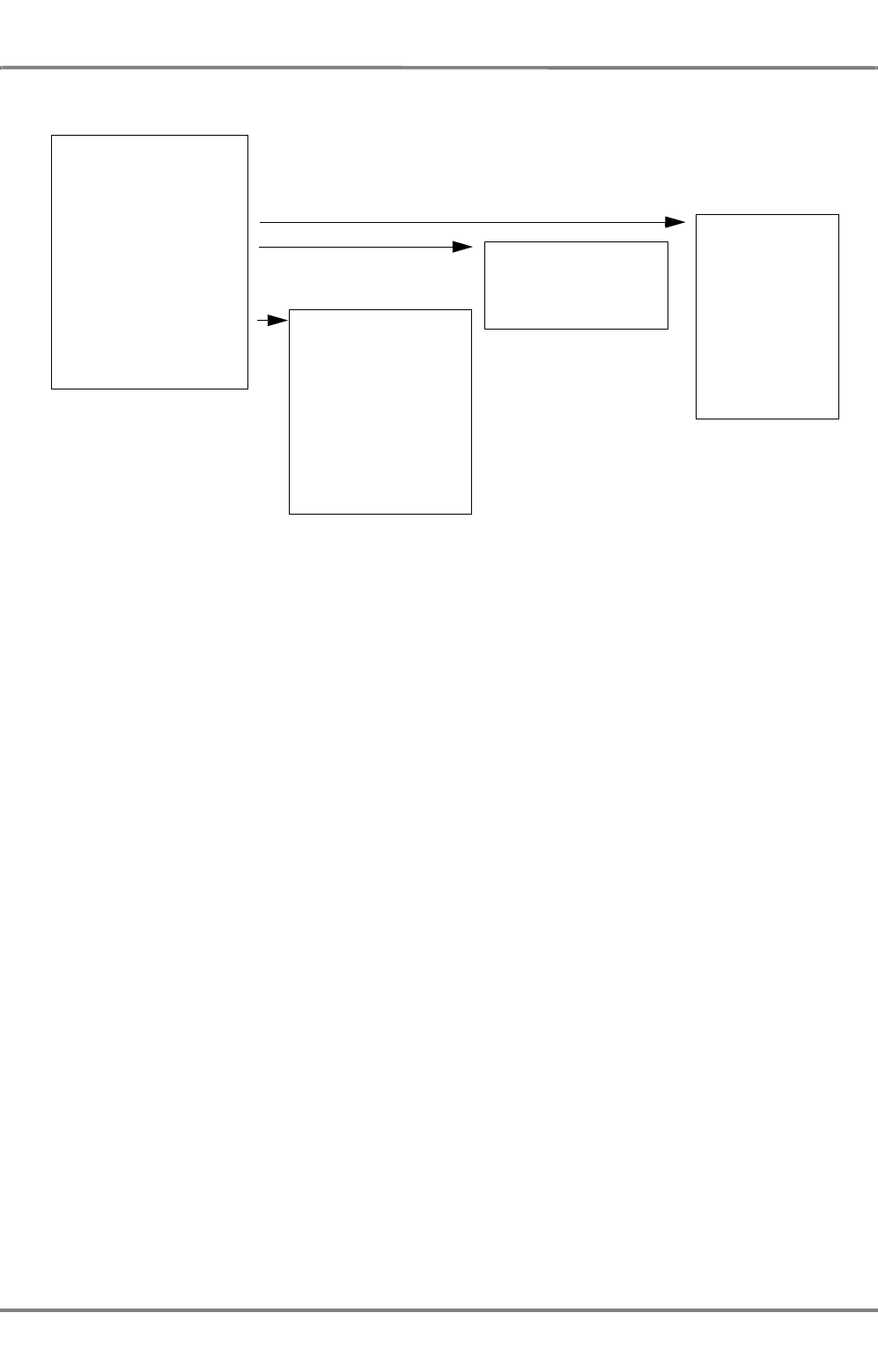
ED 3100 G 140 / 04 (2011-11)
Operating Instructions
III-2 Common Functions for Navigation
III Main Applications.fm / 10.11.11 III-19
NACOS Platinum
Fig. III / 10 Structure of Context Menus
Depending on the system status and the object found under the cursor other or more entries may be
available, for example Clear Trails, Reset PI Lines, Center EBL; the additional entries may also have own
secondary sub-menus.
In some cases it is necessary first to select an item on the screen with the DO key in order to have
access to the relevant context menu.
Examples:
- Select a user made chart object (a symbol, a line or area, an event or a text note) in order to have
access to it via the User Symbols menu.
- Select a waypoint or a leg of the route to get the Route menu with its sub-menus.
Layers
The different graphic overlays in the application area are organized in so called layers. Via a MORE click
into the PPI / chart area you can access the different layers.
The Layer context menu has two main functions
- Selection of visibility of the available layers
- Brightness control of the visible layers.
Off-Center Ship (R)
Set Chart Center (R)
Ship in Center (R)
Layer (R)
Chart
Chart Information (R)
Create LOP
Target (R)
User Symbols (R)
Route
ENC Chart
RADAR Video
Scales
Nav.Tools
Targets
User Symbols
Own Ship
Curved HL
Change to RADAR
Projection
Open ECDIS Chart1
Deselect
Cancel ARPA
Cancel All
Acquire ARPA
REF Target On/Off
Reverse Fusion

NACOS Platinum
ED 3100 G 140 / 04 (2011-11)
Operating Instructions
III-2 Common Functions for Navigation
III Main Applications.fm / 10.11.11
III-20
Fig. III / 11 Layer Context Menu
The availability and the controllability of the different layers are dependent on the active main application
(RADAR or ECDIS mode, etc.). For example in ECDIS you may switch off the radar video and the chart,
but you cannot dim the chart, and in RADAR mode you may switch off the chart, but not the radar video.
Caused by the rules and standards some of the layers are not allowed to be dimmed to complete dark-
ness.
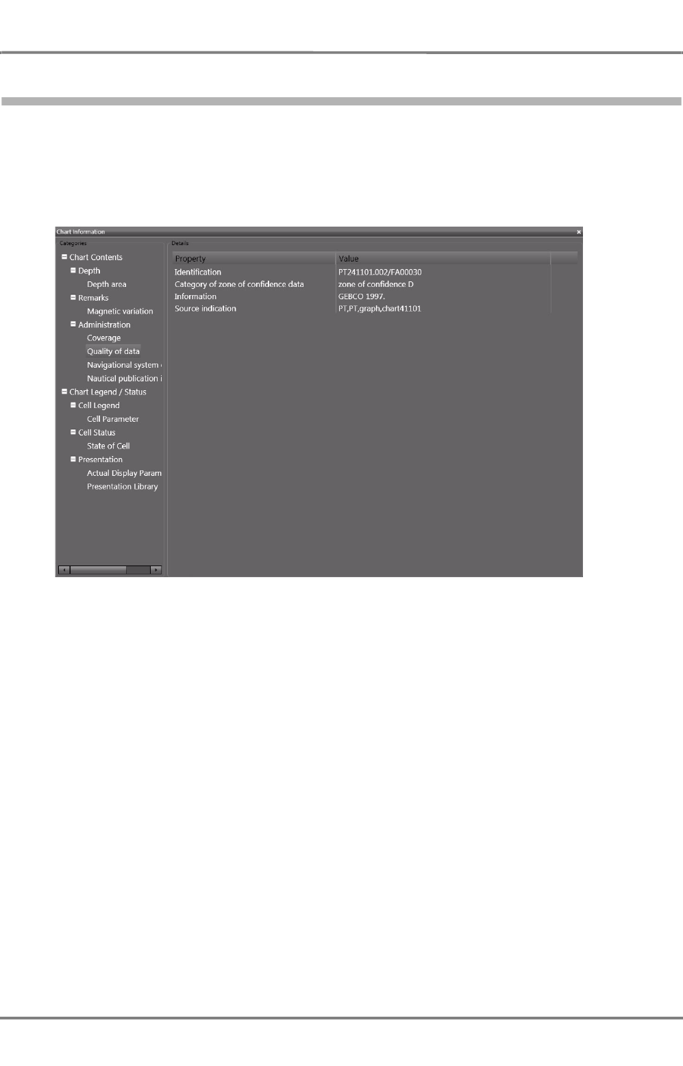
ED 3100 G 140 / 04 (2011-11)
Operating Instructions
III-2 Common Functions for Navigation
III Main Applications.fm / 10.11.11 III-21
NACOS Platinum
2.3 The Chart Information Window
With a MORE click within the PPI/Chart area and then on Chart Information in the context menu, the
Chart Information window is opened.
In this window, information about different criteria of the chart database and the chart cells can be
displayed.
Fig. III / 12 The Chart Information window

NACOS Platinum
ED 3100 G 140 / 04 (2011-11)
Operating Instructions
III-2 Common Functions for Navigation
III Main Applications.fm / 10.11.11
III-22
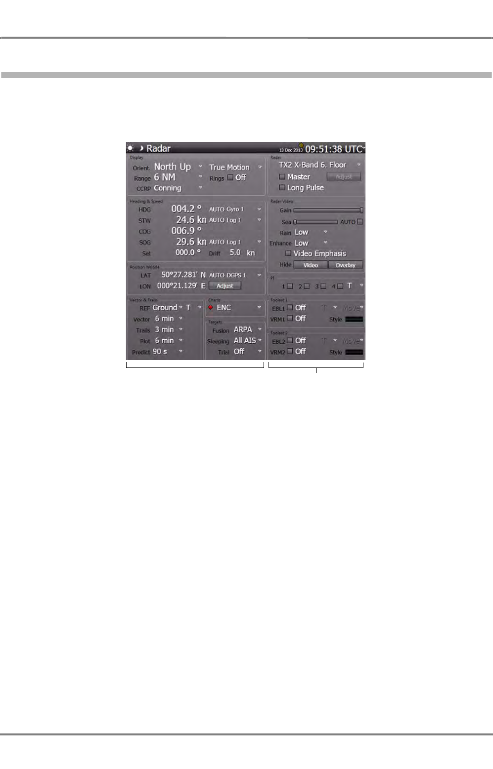
ED 3100 G 140 / 04 (2011-11)
Operating Instructions
III-3 Permanent Area for Navigation
III Main Applications.fm / 10.11.11 III-23
NACOS Platinum
3 Permanent Area for Navigation
The common part for the applications.
As mentioned in the general chapters, the screen ist divided into the application area and the sidebar.
Fig. III / 13 Permanent Area for Navigation
The sidebar itself is divided into the permanent area and the nonpermanent area. The permanent area
contains elements and displays that refer to the settings of the radar, the ECDIS and the entire system.
The elements are grouped. In the following chapters, each group of the application sidebar will be
described separately.
The right part of the permanent area in the sidebar is related to the radar system. It is described in the
chapter RADARPILOT. The left part of th esidebar is fully valid for the RADARPILOT, ECDISPILOT and
the MULTIPILOT. Any dependencies of the controls on the selected main operation mode (RADAR or
ECDIS) are described in the following chapters.
☞ All settings in the permanent area made in RADAR mode or ECDIS mode are synchronized between
the modes, with other words, switching between the modes does not change the common settings
and adjustments.
Apllication Sidebar RADAR Sidebar
see
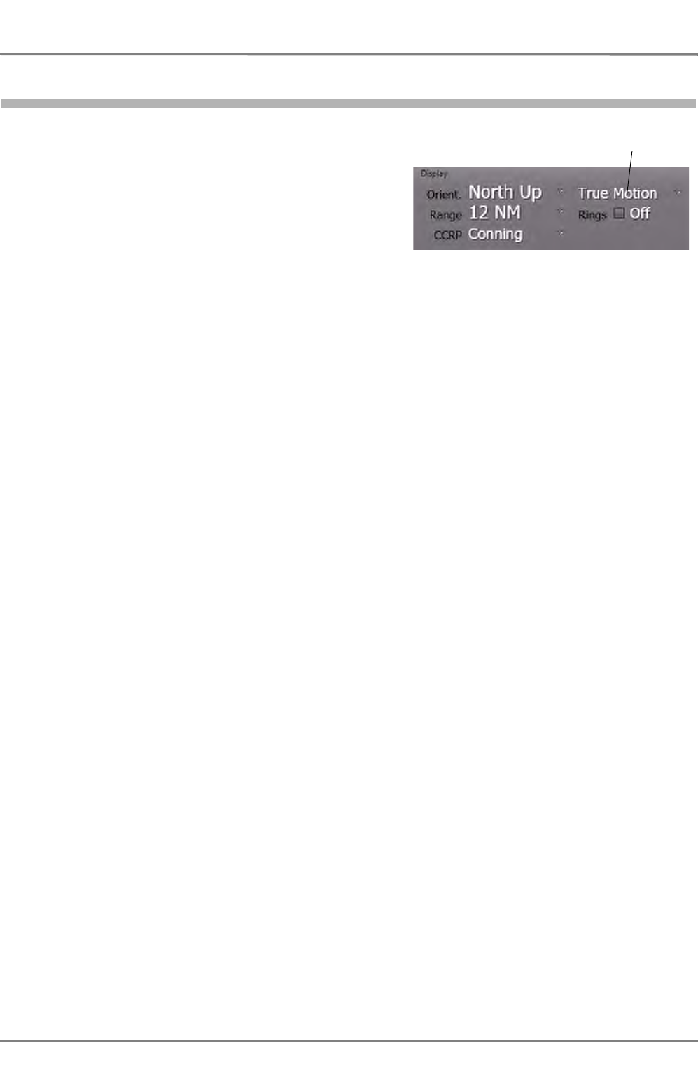
NACOS Platinum
ED 3100 G 140 / 04 (2011-11)
Operating Instructions
III-3 Permanent Area for Navigation
III Main Applications.fm / 10.11.11
III-24
3.1 Display
This group affects the general settings of the radar
display and the chart area of the ECDIS:
- the angular screen orientation
- the movement of the own ship on the screen
- the display range and the range rings
- the CCRP, i.e. the reference point on your ship used for calculation of the system data like COG,
SOG, CTW/STW and position and for calculation of the ship-relative data like bearing and distance
of EBL and VRM and the cursor in the application area.
Screen stabilisation

ED 3100 G 140 / 04 (2011-11)
Operating Instructions
III-3 Permanent Area for Navigation
III Main Applications.fm / 10.11.11 III-25
NACOS Platinum
3.1.1 Orientation
Displays the radar picture and the superimposed chart in three different
ways.
- Head-Up:
The heading of own ship points upwards, the radar video is moving
with the yawing of the ship
- North-Up:
Geographic north points upwards, the radar video is stabilized with the
gyro heading
- Course-Up:
The course which exists at the instant of switch-on or re-orientation of this mode points upwards,
the radar video is thereafter stabilized with the gyro heading.
In Course-Up Mode a click with MORE on the Course-Up indicator takes over the current heading
as the new reference heading.
☞ After switch-over and re-orientation, the target trails are not influenced; they remain visible in the
new mode.
When the ECDIS display mode is selected, the system can additonally be switched into the planning
mode. This mode is called Browse mode. See chapter B - 1.3.2 on page B-8 and section 3.1.5.
Browse mode is only supported in North-Up and Course-Up orientation. Selection of Head-Up automati-
cally switches back to the Monitoring mode.
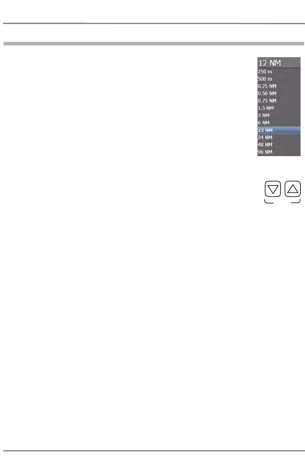
NACOS Platinum
ED 3100 G 140 / 04 (2011-11)
Operating Instructions
III-3 Permanent Area for Navigation
III Main Applications.fm / 10.11.11
III-26
3.1.2 Range
The display range can be chosen from a selection of ten nautical ranges (PPI
radius between 0.25 NM and 96 NM) and two docking ranges (PPI radius 250 m
and 500 m).
☞ In the nautical range and also in the docking ranges, all distances are stated
in NM and all speeds in kn.
☞ If the range selection is done by means of the radar keyboard, the ranges are
selected stepwise (up or down).
The Range can also be set by means of the radar keyboard or by the zoom control.
See chapter 4.1 on page A-34.
RANGE

ED 3100 G 140 / 04 (2011-11)
Operating Instructions
III-3 Permanent Area for Navigation
III Main Applications.fm / 10.11.11 III-27
NACOS Platinum
3.1.3 Rings
Fixed range rings can be displayed. Range rings are concentric circles with the reference position of the
selected CCRP as their centre 1), and are situated at equal distances from one another.
Depending on the selected range, the radii of the rings and the distances between them are different:
Table III / 2 Range Rings
1) For reference position see See chapter 2.1 on page III-16
Range 250m 500m 0,25NM 0,5NM 0,75NM 1,5NM 3NM 6NM 12NM 24NM 48NM 96NM
Distance
Ring 50m 100m 0,05NM 0,1NM 0,25NM 0,25NM 0,5NM 1,0NM 2NM 4NM 8NM 16NM
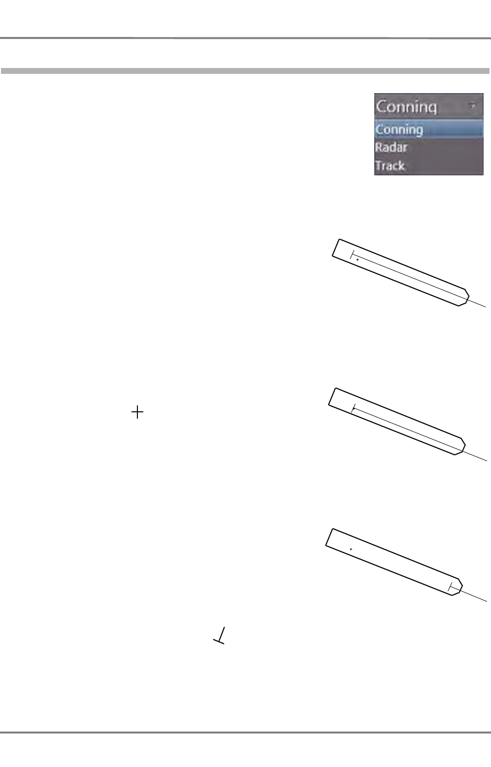
NACOS Platinum
ED 3100 G 140 / 04 (2011-11)
Operating Instructions
III-3 Permanent Area for Navigation
III Main Applications.fm / 10.11.11
III-28
3.1.4 CCRP
The Consistent Common Reference Position can be chosen from three
different possibilities:
- Conning:
The measurements are stated relative to the conning posi-
tion, which is a defined position on the bridge.
- RADAR:
The measurements are stated relative to the position of the
selected radar antenna.It another transceiver is selected, the
reference position is changed automatically. If RADAR is not
selected as CCRP, its location on the ship symbol is marked
by a small cross:
- Track:
Referring to section 2.1 it must be noted here that the
Trackpilot is utilising the data of the so called System Posi-
tion in the bow of the ship for its control purpose and also
for calculation of all ship relative data (course and track
deviation, drift angle, bearing, distance and time to go to
waypoint and wheel over point, etc.). When in the Trackpilot
Section of this manual the term own ship or own ship‘s
position is used, the own ship‘s System Position (at the
bow of the ship) is referenced.
See chapter 2.1 on page III-16 for details on reference systems.
In each case the minimized ship symbol , the speed vector,
EBL, VRM, range rings and stern line are starting from the selected CCRP and all measurement tools and
the graphic cursor are working and indicating relative to this reference point.
Note: The display of the own ship symbol outline in true scale is depending on user selection and
the selected display range, if True Scaled is switched on.
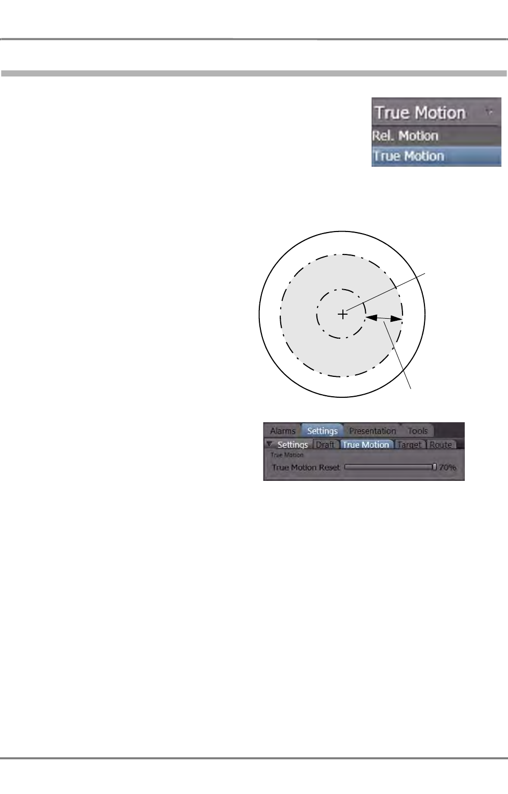
ED 3100 G 140 / 04 (2011-11)
Operating Instructions
III-3 Permanent Area for Navigation
III Main Applications.fm / 10.11.11 III-29
NACOS Platinum
3.1.5 Screen Stabilisation
As far as the screen stabilisation is concerned, there is a choice between
the following:
- True Motion (TM):
The radar video of not moving targets (buoys, beacons, land or
lighthouses) is fixed; the own ship symbol moves across the
screen. The PPI/chart area orientation is North-Up or Course-Up.
Either manually, or automatically by means of a TM reset, the
own ship symbol on the PPI/chart area is reset in good time before the PPI/chart area boundary is
reached; this resetting is done in such a way that the larger part of the PPI/chart area lies ahead
of own ship.
For the ECDIS application, the TM reset
takes place in the instant that the indica-
tion of the CCRP has reached a distance of
10% up to 70% of the chart diameter from
the centre of the PPI.
For RADAR, the value is not adjustable.
See chapter A - 4.1 on page A-34 for
details.
The appropriate value for ECDIS True
Motion Reset value can be set by means
of the slider in the ECDIS > Settings >
True Motion dialog:
- Relative Motion (RM):
Own ship's position is fixed; the radar video moves relative to own ship in accordance with the
movement of own ship. As far as the PPI/chart area orientation is concerned, it is possible to choose
between Head-Up, North-Up and Course-Up.
Centre of the PPI/
chart
10% - 70% of the
radius
Light grey area:
The area where
the off-centered
CCRP or position
indication of the
radar antenna
may be located.

NACOS Platinum
ED 3100 G 140 / 04 (2011-11)
Operating Instructions
III-3 Permanent Area for Navigation
III Main Applications.fm / 10.11.11
III-30
Examples for True/Relative Motion and Head-/North-/Course-Up
In figures III / 14 and III / 15, screen excerpts from two instants of the same scenario are shown sche-
matically for the five Monitoring display modes:
Instant 1
- Own ship's course 60°, speed 20 kn
- Two moving targets, courses 60° and 150°, speed 10 kn for both
-Two fixed targets
- Two grid lines showing the alignment of the electronic chart
Instant 2
The same scenario, but after an own ship's course change to 10° (all other data unchanged).
Displays of the following are set: Own ship symbol, course and speed vectors, past plots of the targets.
Except in the case of True Motion, the centre of the screen excerpt shown is the own ship's position
that was set with Set Center function of the context menu in the PPI/Chart Area.
☞ The display of the own ship symbol is depending on user selection and on the selected display range
if "true scaled" is switched on in the Presentation tab.
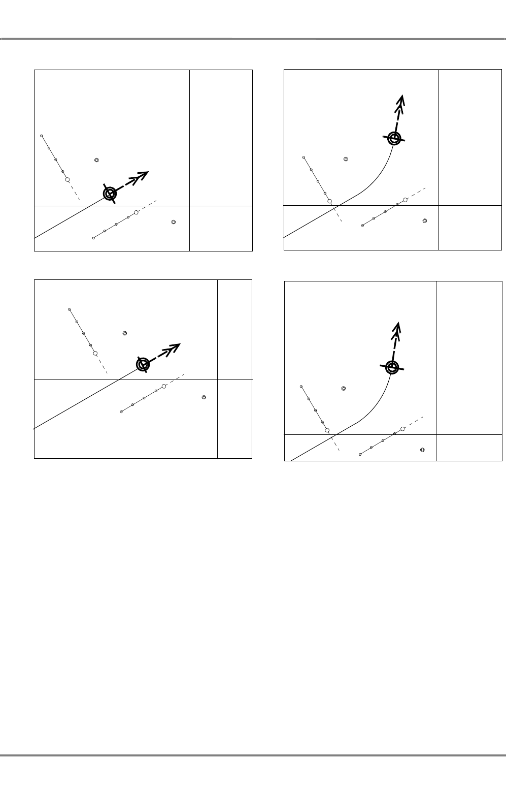
ED 3100 G 140 / 04 (2011-11)
Operating Instructions
III-3 Permanent Area for Navigation
III Main Applications.fm / 10.11.11 III-31
NACOS Platinum
Fig. III / 14 Display in the modes True Motion and Centered Display
True Motion (with true vectors and past plots)
Instant 1 Instant 2
Centered Display (with true vectors and past plots)
Instant 1 Instant 2
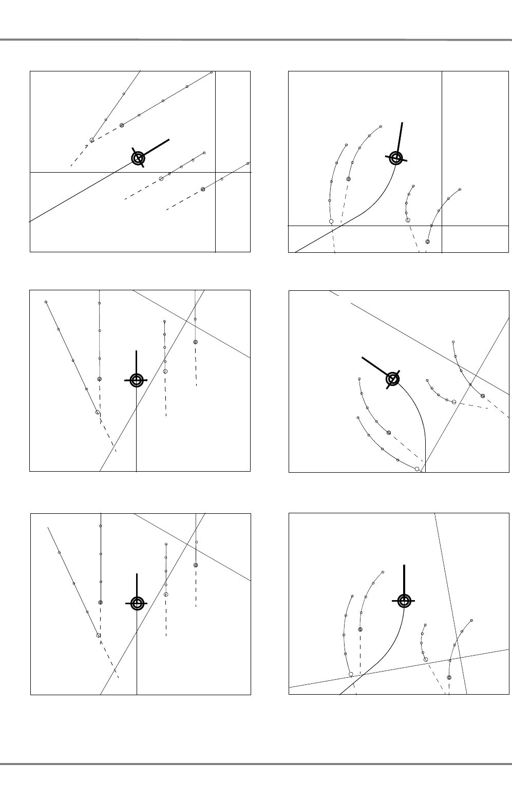
NACOS Platinum
ED 3100 G 140 / 04 (2011-11)
Operating Instructions
III-3 Permanent Area for Navigation
III Main Applications.fm / 10.11.11
III-32
In this mode, the headline is shown as a short, thick line.
Fig. III / 15 Display in the modes North-Up RM, Course-Up RM and Head-Up RM
North-Up RM (with relative vectors and past plots)
Instant 1 Instant 2
Course-Up RM (with relative vectors and past plots)
Instant 1 Instant 2
Head-Up RM (with relative vectors and past plots)
Instant 2
Instant 1

ED 3100 G 140 / 04 (2011-11)
Operating Instructions
III-3 Permanent Area for Navigation
III Main Applications.fm / 10.11.11 III-33
NACOS Platinum
3.2 Navigation Sensors
This chapter describes the navigation sensors available in the system. The main navigation sensors used
for the heading, speed and position instruments are monitored depending on the “sensor selection
mode”. Those sensors which are available twice or more in the installation can be supported by an auto-
matic selection mode indicated by AUTO in the different displays.
- If the selection mode is AUTO the switching over to another sensor of the same type is done with
a warning indicating the new sensor selection.
In AUTO mode the switch over to a manual sensor (Manual Speed or Manual Position) is accompa-
nied by an alarm if the manual data have not been set before.
- If the manual sensor selection is chosen the switching over to the backup sensor must be done
manually after the respective alarm or warning has been given.
In the meantime (until a new sensor has been selected) the system is using the last valid values of
the disturbed or faulty sensor which produced the alarm.
It is required to perform the switch over to the new sensor as soon as possible, but not before its
data have been checked for plausibility and correctness.
Details are given in chapter
V-ALARMS
as required in the explanations to the different sensor alarms.
The automatic selection mode is the default setting after start or restart of the
system.
In any case (in manual or automatic sensor selection mode) the set data for the
sensors running in manual mode must be checked regularly and a real sensor
must be selected as soon as possible.
NACOS Platinum
ED 3100 G 140 / 04 (2011-11)
Operating Instructions
III-3 Permanent Area for Navigation
III Main Applications.fm / 10.11.11
III-34
3.2.1 Integrity Marking of Sensors
According to the currently valid peformance standards, invalid information or information with low integ-
rity shall be clearly marked qualitatively and/or quantitatively. In NACOS Platinum a qualitative marking
of sensors by alarm icons is used 1).
For this purpose the main navigation sensors used for the instruments in the permanent area are contin-
uously monitored by the system. If the signal of a sensor is no longer received or is corrupted, or if it
is marked invalid by the sensor itself or by the NACOS internal sensor monitoring, a respective "sensor
timeout" or a "sensor invalid" alarm message is given for the faulty sensor 2).
In case of activated AUTO selection mode another connected sensor (if available) can automatically by
connected to the respective instrument and the instrument data remain available and valid.
If this is not possible, or if the manual selection mode is used, the sensor will be marked invalid
by an alarm icon shown before the sensor label in the instruments displayed on the permanent
area.
This can happen for the HDG, STW SOG and COG labels in the Heading & Speed group and for the posi-
tion data in front of the LAT and LON labels.
If the manual input mode is selected (caused by sensor failure or decision of the operator) and
the manually set data are used for any navigation sensor, this will be shown by the icon, which
is indicating manual input mode and additionally the warning level 3.
On a vessel at sea manually set sensor data are generally to be treated as doubtful and with low integrity
as they must permanently be monitored and adapted to the real situation by the operator.
1) For a complete list of available alarm icons refer to chapter see chapter V - 1.1 on page V-4.
2) If you need more detailed information about the sensor modes, valid/invalid marking or other details of the
different sensor interface protocols, refer to the Technical Manual delivered with the system.
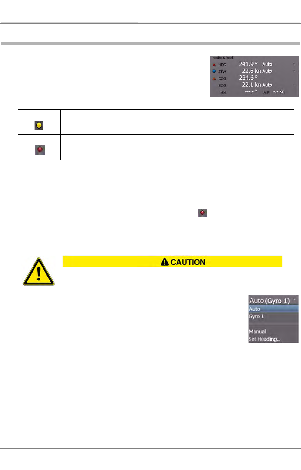
ED 3100 G 140 / 04 (2011-11)
Operating Instructions
III-3 Permanent Area for Navigation
III Main Applications.fm / 10.11.11 III-35
NACOS Platinum
3.2.2 Heading and Speed
This group displays information about the actual values for
heading and speed and offers the possibilities to choose different
heading and speed sensors 1).
In front of each depiction of one of the sensors, there may be a
symbol indicating a warning or an alarm.
Table III / 3 Integrity Marks for Heading/Speed Sensor Data
The meaning of the indicators is explained in detail in chapter
V-ALARMS
.
☞ The values for STW, COG and SOG will go into alarm status if RADAR is selected as the CCRP,
but no radar transceiver is selected.
Heading - HDG
The value for heading is the direction the bow of the own ship is pointing at. It is
derived from the compass system of the ship. Behind the heading value, the actual
choice and the selection mode of the heading sensor is displayed.
AUTO
Means that the heading sensor is chosen by the system automatically. The best
available sensor will be used. If a failure occurs on the actual sensor, the backup
sensor is chosen, if available, and a warning is given.
Gyro x
From the number of gyro compasses that are connected to the system, one can be chosen to be used
as heading sensor. Sensor selection mode is manual.
1) The sensor selection list is depending on the navigation sensors connected to the system.
Yellow Input from the process is disconnected in the software, and the value is entered manually by
the operator
Red Error in the Control and Supervision system, the indication is invalid or the value received
from the sensor is outside the legal limits
Be aware that a missing or wrong speed input to the compass system can also produce
remarkable course errors.

NACOS Platinum
ED 3100 G 140 / 04 (2011-11)
Operating Instructions
III-3 Permanent Area for Navigation
III Main Applications.fm / 10.11.11
III-36
Manual (Option)
The actual course of the own ship can be entered manually. In
case a manual value is present, the indication of the value is
preceeded by a in the same line.
After having changed the heading sensor to manual mode, use the Set Gyro... function in order to enter
the desired value.
☞ This choice is normally not visible. It can only be used for special purposes such as demo systems
etc.
ED 3100 G 140 / 04 (2011-11)
Operating Instructions
III-3 Permanent Area for Navigation
III Main Applications.fm / 10.11.11 III-37
NACOS Platinum
About Speed Sensors
Speed sensors are treated as part of the CCRS. (See chapter III - 2.1 on page III-16 for details). This
means that the indicated speed data and the speed vector dispayed in the PPI/chart area are valid for
the CCRP sected under "CCRP" on page III-28
There may be several speed sensors connected to the system. One of them is chosen by the system on
startup. In the case of speed sensors which transfer the longitudinal speed only, the drift and set can
be entered manually, because those devices cannot detect the effect of leewayand current. As an alter-
native to selection of a speed sensor, it is also possible to input the speed manually, if necessary. If fixed
ARPA targets are available, the speed can also be determined by Reference Target Tracking. See
chapter 7.13 on page A-78 for details.
☞ The speed sensors also include position sensors which transfer not only the position but also the
speed and course made good. Compared to the present-day state of the art, they generally do not
meet the IMO Performance Standards for SDME (Speed and Distance Measuring Equipment, IMO
resolution MSC.96(72). Therefore, they might not be configured in the system, and so it might not
be possible to select them for speed input.
Two different values for the speed of the ship are displayed:
- STW: Speed through Water
Only the longitunial speed (i.e. the speed in ship´s direction) is indicated behind STW. An arrowhead
describes the ahead or astern velocity. The speed through water results in a speed vector described
by CTW, STW. The speed through water often is not equal to the speed over ground, set and drift
may influence the measurement. Speed logs for waterspeed (single axis log) often do only measure
the longitudinal speed, i.e. the speed mainly produced by the propulsion of the ship. In this case
the CTW is equivalent to the actual heading.
The resulting velocity is also indicated as a CTW/STW vector on the HMI and graphically in the PPI/
chart area.
- SOG: Speed over Ground
The speed over ground is the most accurate and best way to determine the ship´s speed. It is often
measured by two-axis logs, doppler-logs or alternatively by position sensors which calculate the
ship´s speed from the difference of positions and the time elapsed while sailing.
The resulting velocity is indicated as a COG/SOG vector on the HMI and graphically in the PPI/chart
area.
It must be ensured that an approved SDME (Speed and Distance Measuring
Equipment) is connected, that means that all speed sensors must accord to IEC
62388 (2007) and to IMO resolution MSC.96(72).
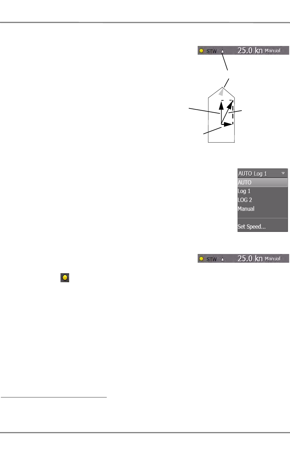
NACOS Platinum
ED 3100 G 140 / 04 (2011-11)
Operating Instructions
III-3 Permanent Area for Navigation
III Main Applications.fm / 10.11.11
III-38
Speed through Water - STW 1)
Next to the depiction STW there is a small indication like an
arrow-head. This is the speed vector indicator. It shows the
direction of the vector addition of the longitudinal and the
transversal own ship´s speed through water.
If the ship is moving straight forward through the water, the
arrow head points upward, if it is moving straight backward,
the arrow head will point downward.
The arrow head may also point into any other direction,
then the transversal speed component makes the ship move
sideways through the water 2).
AUTO
Means that the STW or waterspeed sensor is chosen by the system automatically.
The best available sensor will be used. If a failure occurs on the actual sensor,
the backup sensor is chosen if available, and a warning is given..
Log x
The selected speed log is used as system sensor for water speed. The sensor
selection mode is manual.
Manual
The actual STW of the own ship can be entered manually. In case
a manual value is presenlty used, the indication of the value is
preceeded by a in the same line.
Before having changed the speed sensor to manual mode, use the Set Speed... function in order to
enter the desired value, which should match as good as possible to the real speed through water of your
ship.
1) The selected CTW/STW vector for speed through water is used as the data source for Water Stabilisation of
the targets in the radar PPI/chart area.
2) Transversal speed information is only available if a 2-axis speed log is connected.
Speed vector indicator
Longitunal
Speed
Transversal
Speed
Vector addition
(resultuing Speed)

ED 3100 G 140 / 04 (2011-11)
Operating Instructions
III-3 Permanent Area for Navigation
III Main Applications.fm / 10.11.11 III-39
NACOS Platinum
Own ship symbol with vector.
Water
CTW/STW
Ground
COG/SOG
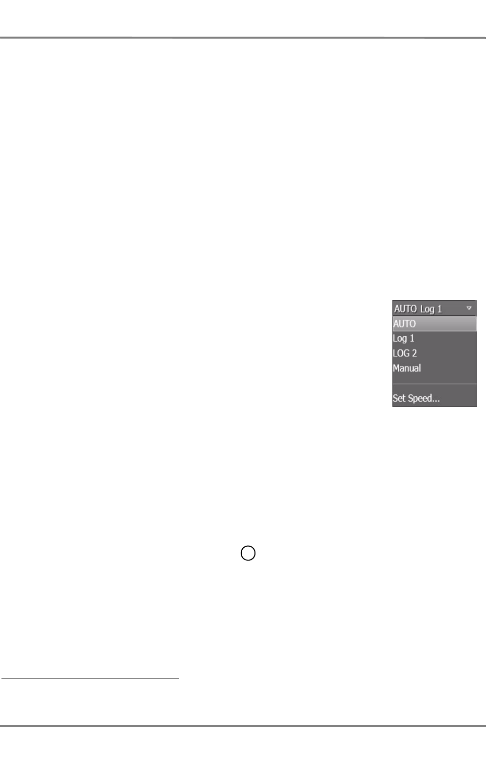
NACOS Platinum
ED 3100 G 140 / 04 (2011-11)
Operating Instructions
III-3 Permanent Area for Navigation
III Main Applications.fm / 10.11.11
III-40
Course over Ground - COG 1)
The value for course over ground is calculated
- by use of the heading and the log sensors (a bottom-track-log for example) or
- computed from the measured values of a sensor and additional information (a water-track-log and
the values for drift and set for example).
- It can also be computed from the difference of own-ship positions within a specified time (normally
delivered by a position sensor in a specific telegram).
The method the COG is computed depends on the sensors selected. For example, in case of the speed
log its longitudinal and transversal speed values together with the heading value are used to calculate
the true course vector over ground. The system decides itself and chooses the best and most accurate
way to compute the COG. In any case the indicated COG is based on the data received from the speed
sensor shown behind the SOG value.
☞ The COG/SOG instrument in the Permanent Area displays course and speed over ground as a data
pair describing the direction and the length of the speed vector over ground.
Speed over Ground - SOG1)
AUTO
Means that the speed over ground sensor is chosen by the system automatically.
The best available sensor will be used. If a failure occurs on the actual sensor,
the backup sensor is chosen and a warning is given.
Manual Sensor Selection
Log x
The selected speed log is used as system sensor for ground speed. If the selected
log is a single axis log, it is advisable to enter set and drift to correct for tidal
currents.
GPS x
Position sensors may be selected as input for SOG values. See also hint on page III-37 for details.
REF TGT
REF TGT
speed input can only be selected on radar systems and if, as a minimum, one tracked target
is selected as a reference target (shown as on the PPI, see chapter A - 7 on page A-55 for
details.)
STW
Sets the SOG to the same value as STW. In this case it is advisable to enter set and drift to correct for
tidal currents.
☞ If set and drift are not set or initialized, it may happen that the COG/SOG data will be made invalid.
1) The selected COG/SOG vector for speed over ground is used as the data source for Ground Stabilisation of
the targets in the radar PPI/chart area.
R1
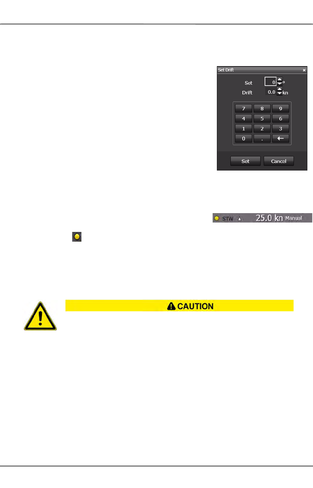
ED 3100 G 140 / 04 (2011-11)
Operating Instructions
III-3 Permanent Area for Navigation
III Main Applications.fm / 10.11.11 III-41
NACOS Platinum
Set Drift
Depending on the choice of sensors, the values for direction and
strength (speed) of the drift are computed by the system or they
have to be entered by the user, in order to get an accurate meas-
urement for COG and SOG. In order to enter the set and drift
manually, open the dropdown lists for SOG, click on Set Drift...
and enter the values in the appropriate fields.
Afterwards, click on Set to accept the values entered.
Manual
The actual STW of the own ship can also be entered manually. In
case a manual value is presently used, the indication of the value
is preceeded by a in the same line.
Before having changed the speed to manual mode, use the Set
Speed... function in order to enter the desired value.
☞ Setting a manual speed value for the SOG instrument often also requires the manual Set and Drift
input, in order to correct for the set and drift created by wind and waves and the current
.
Manual speed and REF TGT speed input are only to be used as temporary solution. In
both cases it must be observed repeatedly if the values used are still valid and stable.
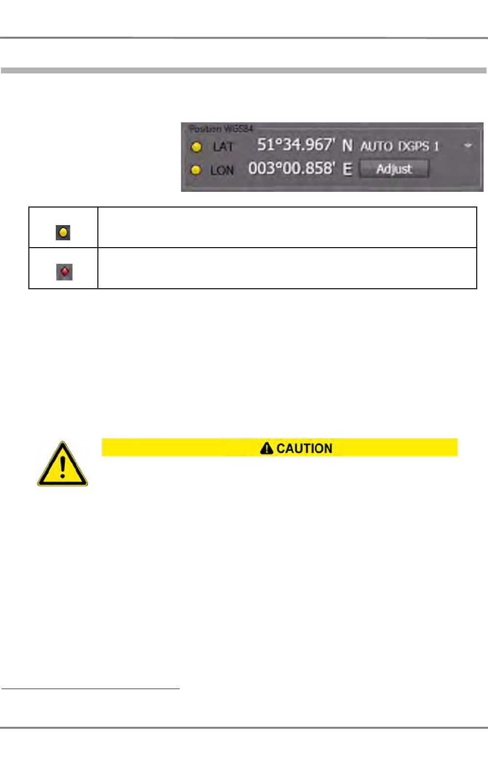
NACOS Platinum
ED 3100 G 140 / 04 (2011-11)
Operating Instructions
III-3 Permanent Area for Navigation
III Main Applications.fm / 10.11.11
III-42
3.2.3 Position
The position display indicates the Lat/Lon values, the position status and its selection mode. With
Adjust, the position dada can optionally be corrected for position errors.
In front of each depiction of the
values LAT/LON, there may be a
symbol indicating a warning or
an alarm.
Table III / 4 Integrity Marks for Position Sensor Data
The meaning of the signs is explained in detail in chapter
V-ALARMS
.
About Position Sensors
Position sensors are treated as a part of the CCRS. See chapter III - 2.1 on page III-16 for details. This
means that the LAT/LON values indicate the position of the selected CCRP (Conning/RADAR/Track). For
this function the sensor locations defined on service level are utilized.
If more than one position sensor is connected to the system, a position monitoring function will auto-
matically be activated and will be running on the MFD 1).
The data transmitted from a position sensor to the system may contain additional information about
validity , sensor type, sensor mode etc. These data are combined in the sensor label shown in the posi-
tion display.
Yellow Input from the process is disconnected in the software, and the value is entered manually by
the operator
Red Error in the Control and Supervision system, the indication is invalid or the value received
from the sensor is outside the legal limits
It must be noted that the necessary accuracy is achieved only if all positions used relate
to the same chart datum, preferably WGS 84.
- When using the system as a planning system, position coordinates obtained
from a chart with a datum deviating from WGS 84 must be converted to WGS
84 User Symbols and route data.
- The only position receivers that may be connected to the NACOS Platinum
system are those that output the position values in the geographical reference
system WGS84 via an interface as per IEC 61162-1.
- It must be ensured that an approved EPFS (Electronic Position Fixing System)
is connected, that means that all position sensors must accord to IEC 62388
(2007) and to IMO resolution MSC. 112(73).
1) This function is a mandatory requirement for ECDIS.

ED 3100 G 140 / 04 (2011-11)
Operating Instructions
III-3 Permanent Area for Navigation
III Main Applications.fm / 10.11.11 III-43
NACOS Platinum
Examples:
Types of sensors: GP (for GPS), GL (for GLONASS), GA (for Galileo), LC (for LORAN C), IN (for INS)...
Modes of sensors: A (for autonomous), D (for differential), P (for Precision), R (for RTK), F (for float
RTK)...
Modes E (for Estimated), M (for Manual), S (for Simulation) are not accepted as valid input data.
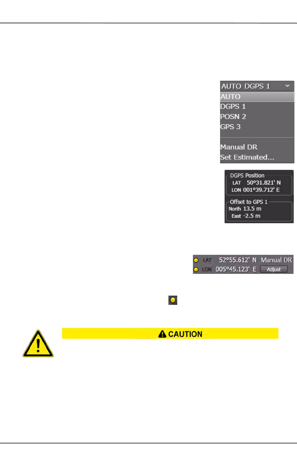
NACOS Platinum
ED 3100 G 140 / 04 (2011-11)
Operating Instructions
III-3 Permanent Area for Navigation
III Main Applications.fm / 10.11.11
III-44
Position Sensor Selection
Changing the position sensor will also have an effect on the position monitoring function.
The sensor selection list is dependent on number, type and mode of the position sensors connected to
the system.
AUTO
Means that the position sensor is chosen by the system automatically.
The best available sensor will be used. If a failure occurs on the actual
sensor, the backup sensor is chosen and a warning is given.
mGPS n
Selects the desired position sensor from the list of available sensors in
the system.
As long as the mouse pointer is positioned above the depiction of a
sensor, the position data delivered by this sensor and also the offset
position of the sensor from the actual CCRP position are displayed in
a tool tip window.
m indicates the sensor mode,
GPS may be replaced by another sensor type,
n indicates the sensor number.
Manual DR
As long as Manual DR is selected, the manually entered posi-
tion will be used as the basis for all further position calcula-
tions by dead-reckoning. This method uses the gyro heading
and the speed of the selected COG/SOG speed sensor to esti-
mate the own-ships position. In case a manual value is
present, the indication of the value is preceeded by a in
the same line.
The accuracy of the dead-reckoned position (shown in the positon display as: Manual DR)
must be checked continually, because its accuracy is very poor and its position error is
increasing over time. For safety reasons, an available position-sensor must be selected as
soon as possible.
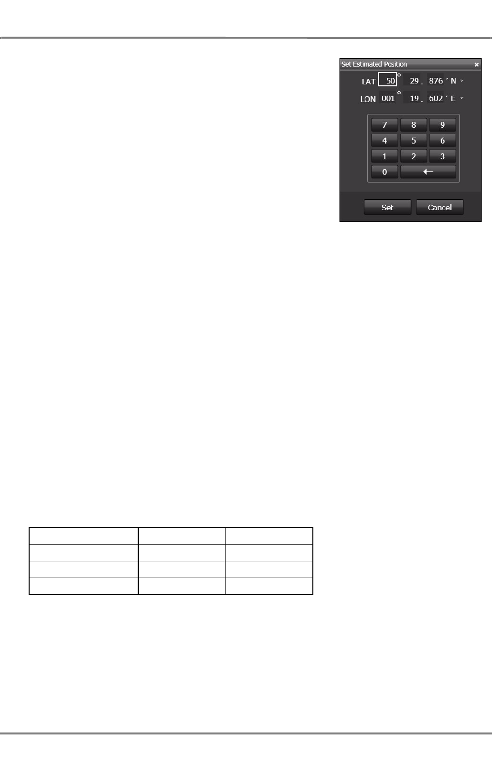
ED 3100 G 140 / 04 (2011-11)
Operating Instructions
III-3 Permanent Area for Navigation
III Main Applications.fm / 10.11.11 III-45
NACOS Platinum
Set Estimated...
The actual position can be entered manually by means of the on-
screen keyboard.
After a position sensor failure the last valid data received from the
sensor are automatically present in the input fields. Be sure to
correct the data input if the last valid data taken over from the
sensor are no longer valid.
Position Monitoring
In addition to the selectable position plot of the 2nd position sensor (see 2nd Past Track) for display in
ECDIS mode, the system provides an automatic position monitoring between the selected sensor and any
other connected position sensor.
In the position instrument you select the main position sensor to be used in the entire system for display
and control purposes. These sensor data are compared to the data received from the secondary available
position sensor. For this purpose the best available secondary sensor will automatically be selected by
the system.
Assumed you have two sensors GPS1 and DGPS2 connected to the system, there are several different
states of the position monitoring process:
1. GPS1 is selected: DGPS2 is used for comparing its position data to the selected position.
2. DGPS2 is selected: GPS1 is used for comparing its position data to the selected position.
3. DR Mode is selected: DGPS2 is used for comparing its position data to the estimated position of the
dead reckoning calculation.
4. Any position (GPS1, -2 or DR Mode) is selected, but none of the secondary sensors is available
(switched off, defective or producing invalid data):
The alarm Redundant Position Lost will be given.
Monitoring Limits
The limits used for the position monitoring process are generated by the system automatically (i.e. there
is no possibility for the operator to have an influence on it). The following table gives an overview about
the dependencies based on the theoretical sensor accuracy.
Table III / 5 Monitoring Limits
Position accuracy Example Limit 1)
1) To avoid unnecessary alarms, an additional speed dependent
lowest limit is used to filter out the natural position noise.
very good DGPS very small
good GPS small
low Loran high

NACOS Platinum
ED 3100 G 140 / 04 (2011-11)
Operating Instructions
III-3 Permanent Area for Navigation
III Main Applications.fm / 10.11.11
III-46
Position Monitoring Alarm
If the defined limit between the two compared positions is exceeded, the alarm Redundant Position
Differs is given. For this purpose the distance in meters between the selected and the secondary posi-
tion is calculated.

ED 3100 G 140 / 04 (2011-11)
Operating Instructions
III-3 Permanent Area for Navigation
III Main Applications.fm / 10.11.11 III-47
NACOS Platinum
Position Adjust
For various reasons, it can happen that the position of the electronic chart on the screen is not in agree-
ment with reality (i.e. with the ship's own position and with the radar or ARPA targets). In such cases,
the Position Adjust function offers the possibility of adding the necessary correction value to the
system position used in the NACOS.
Position Adjust is used to correct a constant position-error (position offset) of the selected position sensor
or of a manually set position in Manual DR mode.
Position Offset
If the displayed LAT/LON position is incorrect, the videos and the target symbols of fixed point-targets
(e.g. buoys or landmarks) do not coincide with the chart symbols of these targets or with the user made
symbols that are entered at the correct positions in the chart.
A position offset of the position sensor can also be made visible without displaying the chart background
on a radar, if you observe the coincidence of AIS target symbols with their target videos:
- If all targets have an offset in the same N/E direction, a position error is very probable.
- If all targets have the same bearing offset, it is more probable that either the radar itself or the
compass system needs to be adjusted.
Correction by Position Adjust
The position error can be corrected manually by making the video or symbol of a fixed target coincide
with its chart symbol:
1. Switch on a sufficiently small display range to be able to observe and measure the position offset.
If no radar targets are available as a reference use other means to determine the position error.
2. Click on the Adjust button in the Position display. In the input dialog which then opens, key in the
North and East values of the offset you want to eliminate. South and West values must be set as
negative values.
Note: If the chart object is located north / east of the relevant radar target you must key in a North /
East value and vice versa. With other words: you must shift the chart object to the radar or ARPA target.
3. Clicking on Set in the input dialog takes over the offset value 1).
4. As a result, the correction values displayed in the Adjust dialog take effect as a position offset and
this offset is added to the position data of the sensor.
The Position Adjust function must be used extremely carefully! An offset is added
to the received position data, which will have an impact on all NACOS applications
based on or using position data!
The position offset has an effect throughout the whole system, i.e. also on the
automatic track keeping. For this reason, it can happen that, as a result of the
position adjust, an alarm message (e.g. the TP Track Limit alarm of the TRACK-
PILOT) is triggered on connected units and that the Trackpilot takes corrective
actions to steer back to the pre-planned track line 1).
1) If this shall be avoided, switch the TRACKPILOT into Heading or Course mode before you apply a
position offset to the system position.
1) 1) Click on Cancel if you want to discard all inputs
NACOS Platinum
ED 3100 G 140 / 04 (2011-11)
Operating Instructions
III-3 Permanent Area for Navigation
III Main Applications.fm / 10.11.11
III-48
• The entire track and chart synthetics move by an amount equal to the position offset. With
other words the own ship's position jumps on the screen (the PPI / chart area) exactly by that
offset.
• The position offset that is entered continues to be displayed in the Adjust dialog.
• In this way, each direction (N/S and E/W) can be corrected by up to 999 m.
• The LAT / LON data are marked with the manual input symbol as long as a position offset
is applied.
5. Check that the other symbols of the chart and the AIS target symbols too now coincide as well as
possible with their radar echoes. If necessary, the steps 2 to 3 can be repeated to correct the posi-
tion offset.
Deleting the Position Offset
The position offset can only be deleted manually by clicking on the Adjust button and entering 0 m for
each direction.
The position offset is not deleted automatically when a different position sensor is selected.
If the entire video has a rotational displacement relative to the chart, this indi-
cates that there is probably a compass error which cannot be deleted by a posi-
tion offset. Either the synchronisation within the compass system is inadequate
(this must then be corrected) or the compass system itself has a static or dynamic
course error. This should, if possible, be corrected in the compass system.
Check regularly whether the position offset is still valid, especially after a change
of positional accuracy from DGPS to GPS and vice versa or after selection of
another position sensor.
When the watch is changing over, the selected offset must definitely be pointed
out to the new officer of the watch.
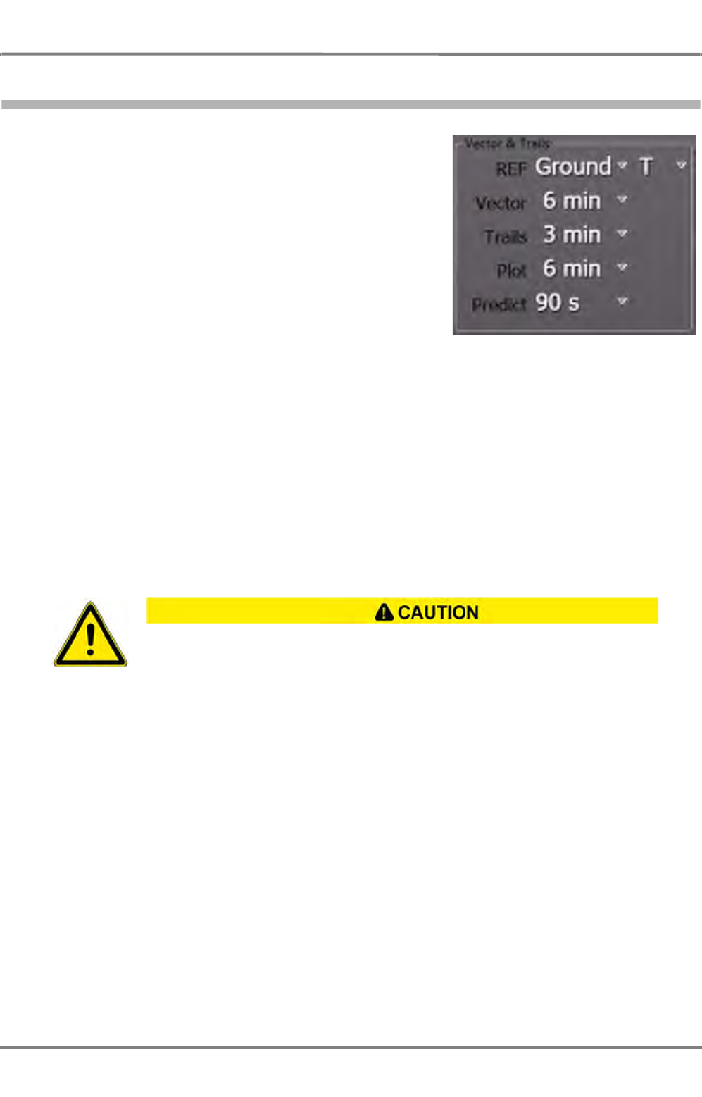
ED 3100 G 140 / 04 (2011-11)
Operating Instructions
III-3 Permanent Area for Navigation
III Main Applications.fm / 10.11.11 III-49
NACOS Platinum
3.3 Vector and Trails
Basically, the display of vectors and trails depends on the way
of speed determination within the system.
Speed Over Ground (SOG), the so-called Bottom-Track, or
Speed Through Water (STW), the so-called Water-Track can
be used in order to compute the vectors for the own ship and
the targets.
The speed vectors of the own ship and of targets, the trails of
targets, the past-position plot and the path prediction for the
own-ship can be configured here.
The speed vector, the target trails and the target´s past posi-
tion plot can be displayed as true or relative.
The own ship´s position plot is only displayed as true plot, i.e. it is independent of the T/REL setting.
☞ The setting T for true or REL for relative measurements is valid for all vectors and trails within all
navigational applications of an MFD.
As mentioned before, the calculation principles for relative or true data have some important differences:
The relative data are calculated directly by the ARPA. The ARPA uses the plots of consecutive antenna
scans in order to calculate relative course and speed of the target. Out of this, CPA and TCPA can be
calculated.
In order to calculate true data of a target, the own ship´s course and speed must be known. The accu-
racy of the true data calculation depends on the accuracy of the sensors from which the own ship´s
course and speed are provided.
If there is any doubt that the own ship´s speed data are not correct, use the REL
target data and PPI presentation for collision avoidance purposes!

NACOS Platinum
ED 3100 G 140 / 04 (2011-11)
Operating Instructions
III-3 Permanent Area for Navigation
III Main Applications.fm / 10.11.11
III-50
3.3.1 Ground / Water Stabilisation
For true vectors and trails it can be selected if the ground speed or water speed based stabilisation shall
take place. Ground stabilisation is normally used for all kind of navigational functions. Water stabilisation
is often used for anti-collision functions. In case of relative display mode, the stabilisation is not relevant.
Select
- Ground
for Bottom Track computation. The speed over ground (see COG/SOG) will be
used to determine the true vectors and trails.
- Water
for Water Track computation. The speed through water (see CTW/STW) will
be used to determine the true vectors and trails.
The position plot of the own ship and the path prediction are always ground stabilised (i.e. use the COG/
SOG vector).
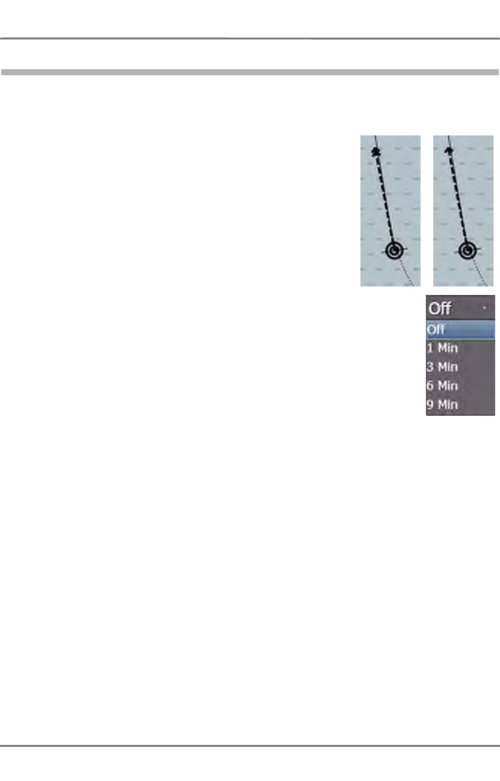
ED 3100 G 140 / 04 (2011-11)
Operating Instructions
III-3 Permanent Area for Navigation
III Main Applications.fm / 10.11.11 III-51
NACOS Platinum
3.3.2 Vector
The direction of the own ship speed vector corresponds to the existing
course of the own ship. The length corresponds to the existing speed
of own ship.
Together with the calculated speed vectors of the tracked targets, the
display of the speed vector can be switched on and off, and the time
represented by the displayed vectors can be specified. Furthermore, it
can be seen from the vector symbol of own ship whether the vector is
relative to the sea (Water selected in Stabilisation = one arrow-
head) or relative to the bottom (Ground selected in Stabilisation =
two arrow-heads).
Vectors of targets can be displayed as true or relative. In relative
vector mode the own ship´s vector is not shown. See chapter 3.1.5 on
page III-29 for graphic examples.
The length of the vectors depends on the time that is selected in the
dropdown-list.
Own ship symbol with vector.
WaterGround
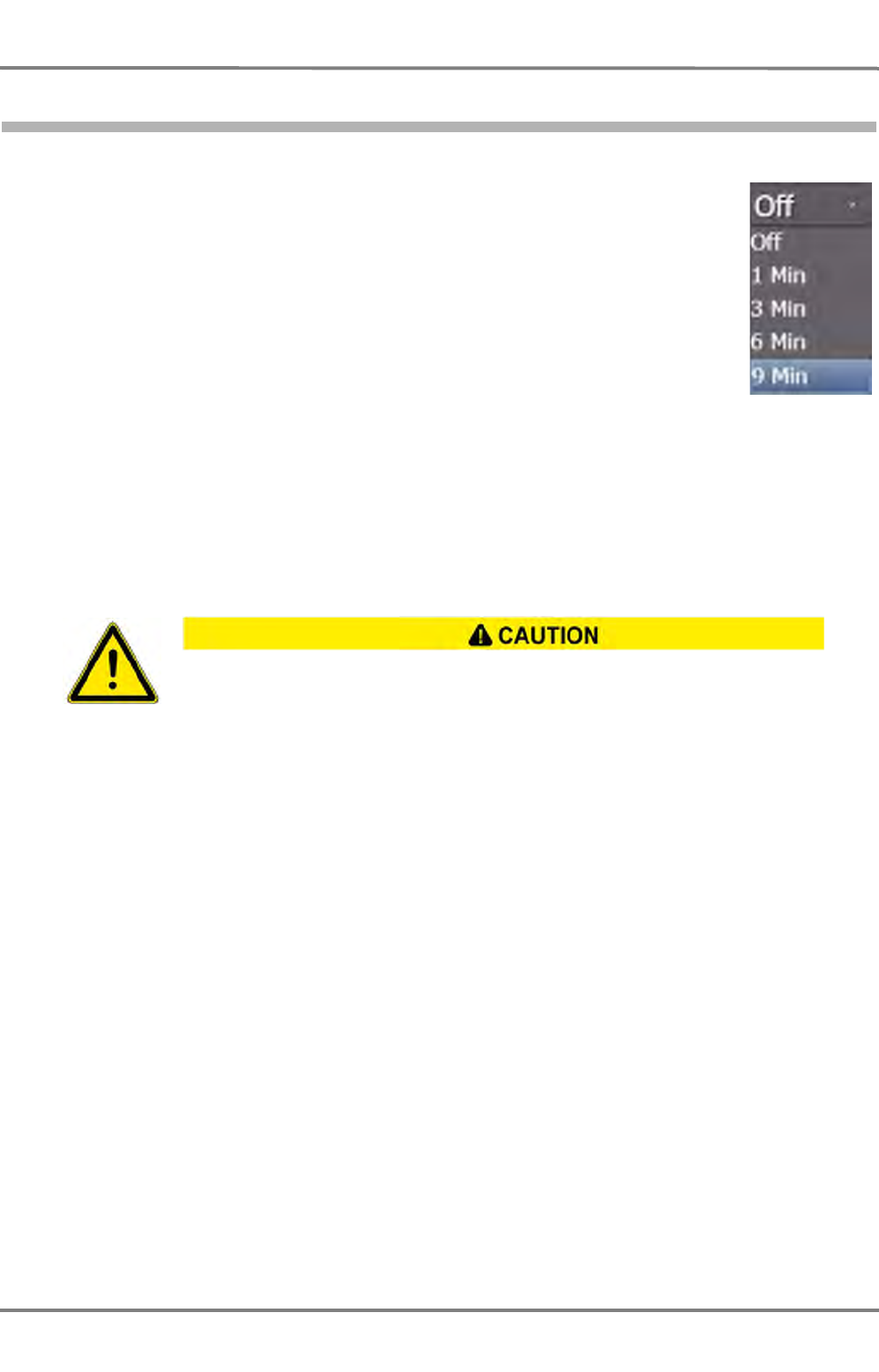
NACOS Platinum
ED 3100 G 140 / 04 (2011-11)
Operating Instructions
III-3 Permanent Area for Navigation
III Main Applications.fm / 10.11.11
III-52
3.3.3 Trails
For radar echoes moving on the PPI, video trails can be displayed. These trails can be
used as synthetic afterglow of the target video. Trails are generated from previous
antenna scans and can be varied as follows:
- The display of trails can be switched on and off.
- Their length can be specified.
- If the screen stabilisation is set to Rel. Motion, the trails can be displayed with
the PPI/chart area orientation North-Up and Course-Up relative to own ship or
with true (absolute) orientation, i.e. in relation to the sea bottom or water stabi-
lized.
- The trail history can be deleted so that they have to build up again
• by the setting Off in the menu and selecting the time again
• by a MORE click into the PPI and selecting Clear Trails
In the true display mode, trails make it possible to reach a conclusion quickly about the manoeuvre
performed by radar targets. In the relative display, the trails provide a quick overview of the danger situ-
ation (a constant bearing can quickly be recognized). However, only qualitative information can be
obtained from them.
Switching the Display of the Trails On and Off
The display of the trails is switched on and off by clicking on the Trails field.
Specifying the Length of the Trails
Click on the Trails field with the MORE key; then, in the dialog that is opened as a result, click on the
desired time
In the Trails field, the length currently being selected is indicated, i.e. the max. length of the trails on
the PPI.
Switching the Trails to Relative or True Display
The switch-over is performed by clicking into the Relative/True field in the Vectors & Trails group.
This selection is then also valid for target vectors and their past plots.
Deletion of Trails
Click on the PPI area with the MORE key. In the dialog that is opened as a result, click Clear Trails
with the DO key.
☞ The trails are also deleted whenever a switch-over occurs which changes the entire radar video
transceiver selection or range, but they then appear again and build up over time.
If the trails are lengthened, they reach the new specified length only after the time differ-
ence (i.e. in the case of switching over from 4 to 12 minutes, 8 minutes will pass before
the trails correspond to a length of 12 minutes).
The reduction of the trail length too takes some time.
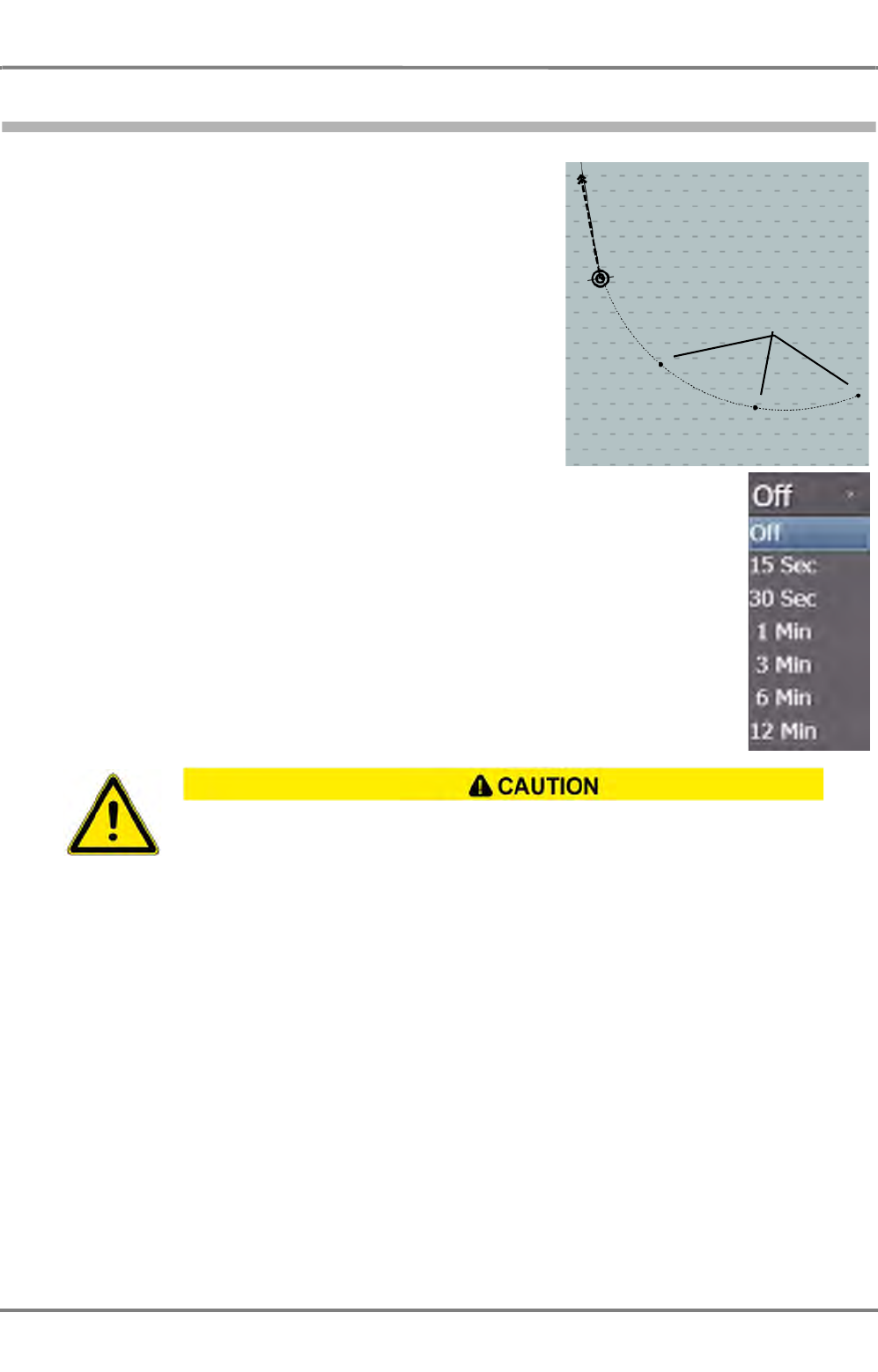
ED 3100 G 140 / 04 (2011-11)
Operating Instructions
III-3 Permanent Area for Navigation
III Main Applications.fm / 10.11.11 III-53
NACOS Platinum
3.3.4 Plot
The past position plot corresponds to the past movement of
the own ship. On it, there are four time markers, whose
distance apart in time can be set. The setting of the time
marker spacing also defines the entire length of the plot that
is displayed. This setting and the on/off switching of the past
plot display take place in common with the past plots and
time markers of the targets.
Plots can not be deleted, so that they do not have to build
up again after switching them off.
The length of the past plot depends on the time that is
selected in the dropdown-list. The plots can be displayed as
relative or true. In REL mode the own ship´s plot is not
shown. The way of displaying plots is switched together with
the vectors and trails of targets in combination (T/REL selec-
tion).
If the time interval for past position plots is lengthened, it reaches the new specified length
only after the time difference has passed (i.e. in the case of switching over from 6 to 12
minutes, 6 minutes will pass before the past position plots correspond to a length of 12
minutes).
The reduction of the interval too takes some time.
Time markers
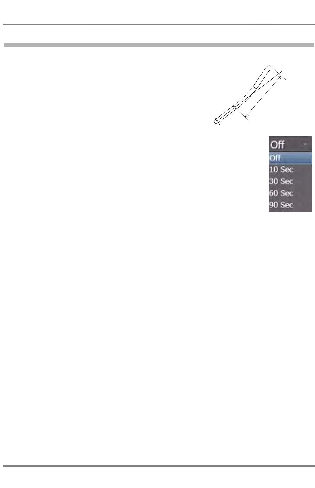
NACOS Platinum
ED 3100 G 140 / 04 (2011-11)
Operating Instructions
III-3 Permanent Area for Navigation
III Main Applications.fm / 10.11.11
III-54
3.3.5 Predict
In the small display ranges up to 1.5 NM, depending on the
size of the symbol, it is possible to display the probable track
(the predicted path) along which the own ship will travel if it
maintains its existing rate of turn and its existing speed. The
prediction time can be set here.
In comparison to the own ship symbol in true scale, the
prediction graphics is drawn with thinner lines.
The prediction length can be set by the time value in the
drop down list belonging to the Predict setting.
Prediction
time
Heading
Line
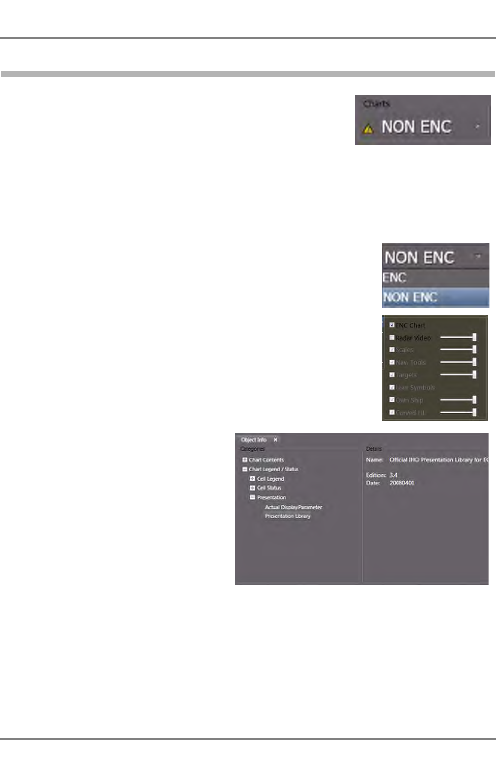
ED 3100 G 140 / 04 (2011-11)
Operating Instructions
III-3 Permanent Area for Navigation
III Main Applications.fm / 10.11.11 III-55
NACOS Platinum
3.4 Charts
On the RADARPILOT there is the option to overlay the radar video
and vector charts 1). Chart overlay can be switched on and off by the
ENC drop down menu.
The chart content itself can be adjusted to an operator selectable
level in the same way as in ECDIS mode or on the ECDISPILOT.
Select Presentation, ENC and Display in the non-permanent expander to access the details of possible
settings. On the same expander the displayed depth contours and depth shades can be influenced.
☞ It is recommended to reduce the number of chart elements displayed on the radar PPI as far as
possible when radar monitoring has priority.
Determining the edition number
In order to determine the edition number of the presentation library, right-
click in the application area and choose Object info.
In the lower part of the application area,
a new window opens. Click on Chart
Legend, Presentation, Presentation
Library. In the Details group the edition
number is displayed.
1) Other selectable chart types will be made available in future. If installed on your system, raster charts cannot be
selected for overlay on the radar PPI.

NACOS Platinum
ED 3100 G 140 / 04 (2011-11)
Operating Instructions
III-3 Permanent Area for Navigation
III Main Applications.fm / 10.11.11
III-56
3.4.1 The Chart Status Line
Fig. III / 16 The Chart Status Line
Title
Chart: The Chart Status Line is always visible if a Vector Chart Application is active, e.g. in ECDIS as
well as in Chartradar mode
Warning
Non ENC (incl. yellow warning symbol), this is only visible if the ENC vector charts on screen and at
least one part of the screen is filled with data from a "Non Official Vector Chart".
In the Cursor-Tool-Tip of this part of the screen the text: "Non-HO data may not be used for navi-
gation. Please refer to paper chart." will be visible in that part of the screen.
Category
- Standard is the IHO Standard selection for visible chart objects
- Base is the IHO Definition for the minimum required selection of visible chart objects
- All means that all chart objects are visible, except objects for data quality indication (data quality
objects mostly overwrite the whole screen, therefore a special button exists in the presentation
menu)
- Customized means that the user´s selection of visible chart objects is displayed
If in the Customized mode at least one visibility group is switched off, then the appropriate mode
and an additional '-' character will be displayed.
If in the Customized mode at least one visibility group is added, then the appropriate mode and
an additional '+' character will be displayed.
In the Cursor-Tool-Tip of this part of the screen the details of the actual selections are displayed.
Date Dependent
Always: Is only visible if in the presentation menu the selection button "Date Dependent" is set to
"Always".
In the Cursor-Tool-Tip of this part of the screen the text: "Date dependent objects are always
visible. Information displayed may be incorrect for the present date and time." will be visible.
Depth
[m]: The actual units for chart depth values belonging to the chart cell at the own ships position in True
or Relative Motion mode or at the center position of the chart area in Browse mode.
Title Warning Category Date Dependent Depth Status

ED 3100 G 140 / 04 (2011-11)
Operating Instructions
III-3 Permanent Area for Navigation
III Main Applications.fm / 10.11.11 III-57
NACOS Platinum
Status
Overscaled Xn.n: The chart cell at the own ships position in True or Relative Motion Mode or at
the chart centre position in Browse Mode is displayed with a larger scale than defined for this cell. The
actual overscale factor is displayed as Xn.n. (e.g. X2.5 means that the chart is displayed with Range 2.5
times smaller than normally defined).
The text Better scale available will be displayed here (additionally) if a chart is available at the same
position with a better 'Navigation purpose' (larger scale). More chart details will be made visible if you
change to a smaller display range scale. The text No ENC available will be displayed here if no chart
with an appropriate scale exists at the own ship´s or center position. In the Cursor-Tool-Tip of this part
of the screen a detailed text will be displayed additionally.
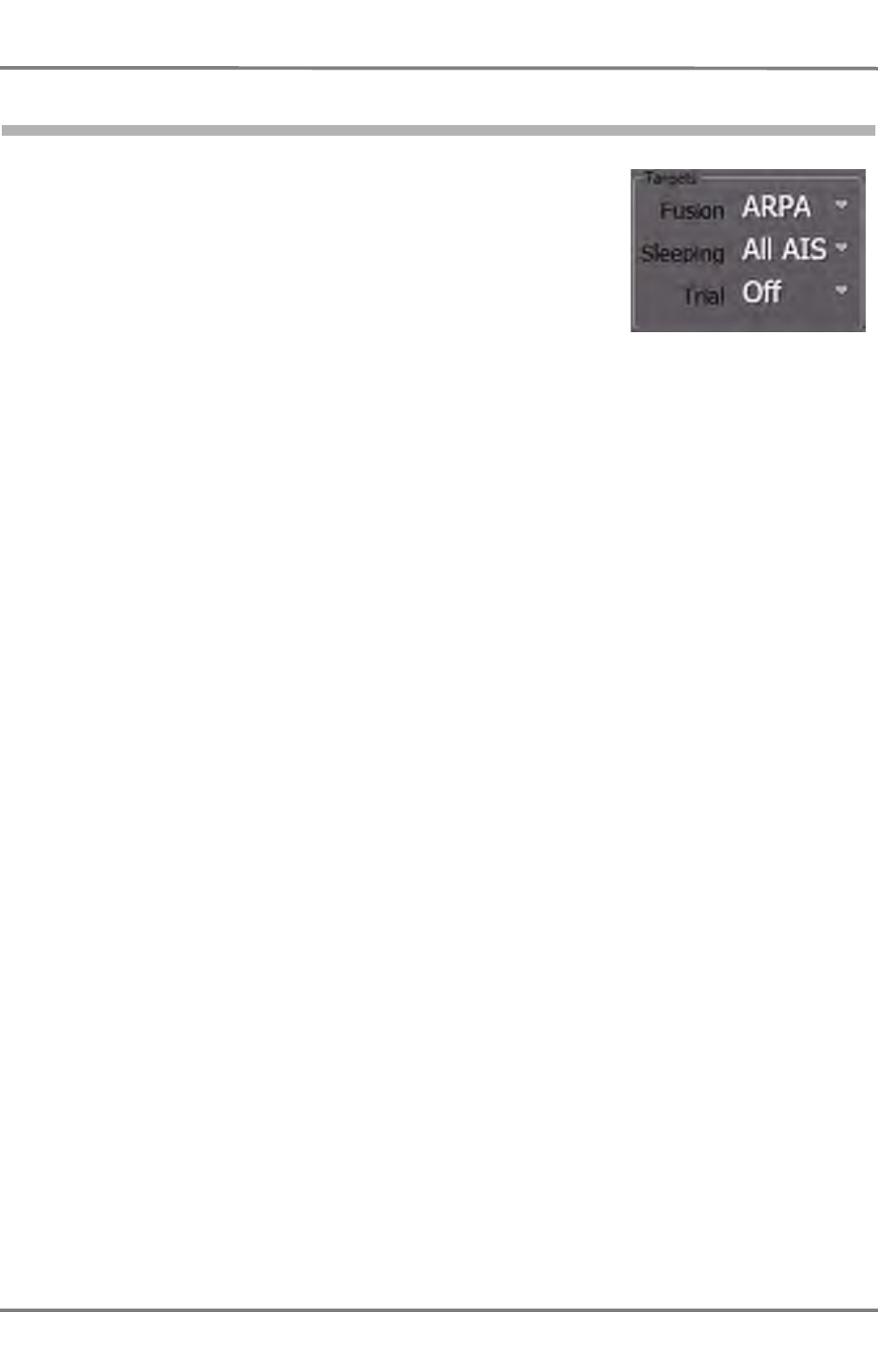
NACOS Platinum
ED 3100 G 140 / 04 (2011-11)
Operating Instructions
III-3 Permanent Area for Navigation
III Main Applications.fm / 10.11.11
III-58
3.5 Targets
ARPA and AIS targets can be displayed simultaneously on the PPI. In
some cases it is possible that one and the same object is tracked as
an ARPA target and also activated as an AIS target. If the ARPA and
AIS target have similar data for distance, course and speed, they can
be fusioned. This means that they are treated as one target as long
as the similarity is existant. The limits for the similarity of the data can
be defined by the operator. See chapter 3.5.1 on page III-59
In other cases it is possible that the two targets are treated as two
different objects.
Anyway under Fusion, the system can be set in a way that one type of targets has priority being
displayed. Nevertheless, both types of targets are still tracked or remain activated in the background.
Independent of the selected priority in the PPI it can be selected for an individual target which data and
graphics shall be shown. See chapter 7.2 on page A-59, "Reverse Fusion" for details.
Additionally it can be selected under Sleeping which type of sleeping AIS targets are to be displayed
continuously.
With the selection Trial the trial manoeuvre function can be activated or switched off. See chapter 7.12
on page A-72 for details.
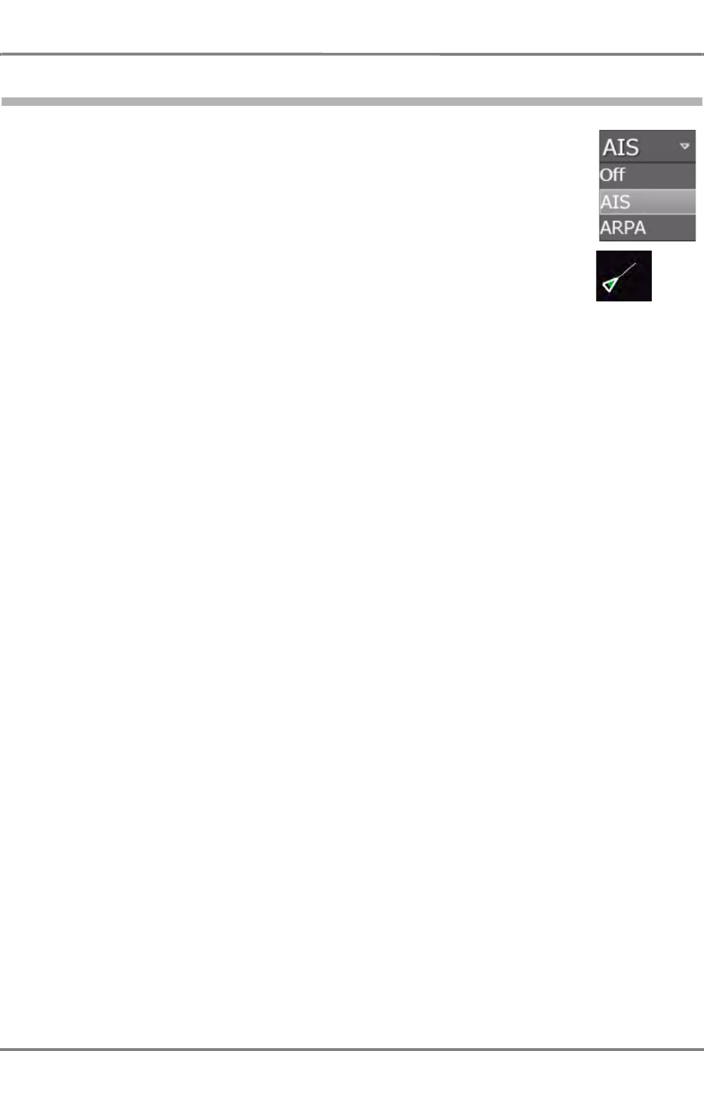
ED 3100 G 140 / 04 (2011-11)
Operating Instructions
III-3 Permanent Area for Navigation
III Main Applications.fm / 10.11.11 III-59
NACOS Platinum
3.5.1 Fusion
Defines temporarily the priority for showing the ARPA or AIS target symbol and
target data in case that the defined target association limits are fulfilled. See chapter
3.5.1 on page III-59 for details about target fusion function and settings.
Fusioned radar echo
and AIS activated
target, AIS symbol is
displayed.

NACOS Platinum
ED 3100 G 140 / 04 (2011-11)
Operating Instructions
III-3 Permanent Area for Navigation
III Main Applications.fm / 10.11.11
III-60
3.5.2 Sleeping Targets
AIS targets are divided in Class A or Class B targets.
- Class A are commercial vessels,
- Class B are leisure crafts
With this selection list it can be chosen which types of sleeping AIS targets are
displayed in the PPI continuously and are available in the target list.
☞ Even if the AIS target display is switched off for above mentioned vessels (i.e. even if None is
selected), all received AIS target information is continuously processed in the background.
In any case those AIS targets being classified as Dangerous can be activated automatically if this
function is not switched off. (See chapter 7.5 on page A-62). If AIS targets are already tracked and
their display is switched off in the above menu, already activated targets remain in the PPI and in
the target list.

RADAR


ED 3100 G 110 / 02 (2011-10)
Operating Instructions
A-1 General Information
A RADAR.fm / 10.11.11 A-3
NACOS Platinum
1 General Information
NACOS Platinum
ED 3100 G 110 / 02 (2011-10)
Operating Instructions
A-1 General Information
A RADAR.fm / 10.11.11
A-4
1.1 RADAR Safety
The radar can perform its safety function only if it is in proper state. Observe the following rules to
ensure correct functioning of the radar.
- Check the radar’s transmission power and the receiver sensitivity regularly by means of the perform-
ance monitor – see RADAR part of the operating instructions.
- Position receivers connected to the NACOS Platinum system must comply with the standard IEC
61162-1, which largely corresponds to NMEA 0183.
- ARPA target data directly depend on the accuracy and proper functioning of the selected speed
sensor and the gyro compass.
- Correct interpretation of indicated data requires knowledge about the implemented Consistent
Common Reference System (CCRS). See chapter III - 2.1 on page 16.
1.1.1 RADAR Safety – Electrical Systems
☞ If the units are to be disconnected from the ship's mains, keep in mind that each antenna unit, each
transceiver electronics unit and each indicator has its own supply of power from the ship's mains.
If synchro transmitters are used for the transfer of signals, e.g. transfer of the heading signal from
the compass system, a dangerous voltage is present in the units until the reference voltage is
switched off.
Pay particular attention to the notes and warnings referring to possible faults in
the radar display, since such faults can impair the detection of targets.
HIGH VOLTAGE!
Even when the equipment is switched off, there can be dangerous voltage present
at exposed contacts in the units. Therefore, before a unit is opened, it must be
ensured that the voltage supply to the unit is disconnected from the ship's mains,
and that it remains disconnected.
Because of the capacitors contained in the units, there can be a dangerous
voltage present in any unit several minutes or even for hours after switching off
and disconnection from the mains supply. The different electronic units of the
RADAR system may be opened by qualified, trained persons only.
If it should be necessary to work on gearboxes while they are opened, pay special
attention to the setting of the high-voltage supply switch (interlock). It is situated
inside the gearbox and switches off the high voltage of the transceiver as soon
as the cover of the gearbox is opened. BUT: For service purposes the interlock
can be set into a position that high voltage is present inside the gearbox. Refer
to the technical manual for details.
ED 3100 G 110 / 02 (2011-10)
Operating Instructions
A-1 General Information
A RADAR.fm / 10.11.11 A-5
NACOS Platinum
1.1.2 RADAR Safety – Radiation
☞ There is no international agreement about the danger posed by high frequency radiation of the kind
produced by the radar systems. In most countries, a radiation density exceeding 100 W/m2 is
considered dangerous; in some countries, values over 10 W/m2 are regarded as not being
completely safe. If in doubt, observe the applicable local regulations, and always ensure minimum
possible exposure.
Table A / 1 Radiation danger zone of radar antennas
WARNING! ELECTROMAGNETIC RADIATION!
Do not enter the radiation danger zone of the rotating antenna, and make sure
that no other person enters the danger zone. See table A / 1.
Before working on the antenna unit, the antenna switch on the unit must be set
to 0 and the transceiver must be disconnected from the ship's mains.
Antenna Type Transceiver
A=Up B=Down
Radius of the Radiation Danger Zone
Radiation Density
100 W/m2Radiation Density
50 W/m2Radiation Density
10 W/m2
5 ft X-Band 12.5 kW, Version A 1.4 m 2.8 m 14 m
25 kW, Version A 2.1 m 4.2 m 21 m
25 kW, Version B 1.65 m 3.3 m 16 m
8 ft X-Band 12.5 kW, Version A 0.65 m 1.4 m 7 m
25 kW, Version A 1.3 m 2.6 m 13 m
25 kW, Version B 0.9 m 1.8 m 9 m
14 ft S-Band 30 kW, Version A 1.3 m 2.6 m 13 m
30 kW, Version B 0.7 m 1.6 m 7.8 m
NACOS Platinum
ED 3100 G 110 / 02 (2011-10)
Operating Instructions
A-1 General Information
A RADAR.fm / 10.11.11
A-6
1.1.3 RADAR Safety – Mechanical Systems
TURNING DEVICES!
When the radar system is switched to ON, it is possible that, instead of the
expected antenna, a different one will begin to rotate depending on the settings
and configuration adjusted before shutdown of the radar system.
Therefore, it must be ensured beforehand that all antennas can rotate freely and
that there are no persons in the danger zones of all antennas.
Before starting work in the vicinity of a radar antenna, make sure to switch off
the man-aloft switch which is situated on the bottom side of the gearbox. Refer
to the technical manual for details.
CRUSHING HAZARD!
Gearboxes and other mechanical units of the RADAR system may be opened by
qualified, trained persons only.
DANGER OF VIOLENT PRESSURE TO HANDS AND FINGERS!
Uncovered toothed belts and wheels inside the housing.
Make sure the MAN ALOFT SWITCH is set to "0" when working at the opened
gear box!
ED 3100 G 110 / 02 (2011-10)
Operating Instructions
A-1 General Information
A RADAR.fm / 10.11.11 A-7
NACOS Platinum
1.2 Current IHO Standards / Regulatory Approvals
According to the international convention for the Safety of Life at Sea (SOLAS) chapter V radar equip-
ment is classified into three categories depending of the size of the ship. The RADAR Platinum series is
approved for the highest two categories CAT 1 and CAT 2. The table below provides a summary of capa-
bilities and differences for both categories as implemented in this radar series.
Table A / 2 Categories of RADAR
If the CHARTRADAR option is installed, above categories are extended with the suffix C as follows:
Category of ship/craft
CAT 2 1)
1) Earlier classified as 12" radar
CAT 1 2)
2) Earlier classified as 16" radar
Size of ship/craft 500 gt to <10000gt All ships/craft ≥10000 gt
Minimum operational display area diameter 250 mm 320 mm
Minimum display area 270 mm x 270 mm 340 mm x 340 mm
Usually used monitor for Platinum 22’’ TFT 26’’ TFT
Auto acquisition of targets Yes Yes
ARPA target capacity 40 40
Activated AIS target capacity 40 40
Sleeping AIS target capacity 200 200
Trial manoeuvre Yes Yes
With 22” TFT monitor: CAT 2 C
With 26” TFT monitor: CAT 1 C
The NACOS Platinum and especially the RADARPILOT Platinum is not yet approved for High
Speed Crafts (HSC)
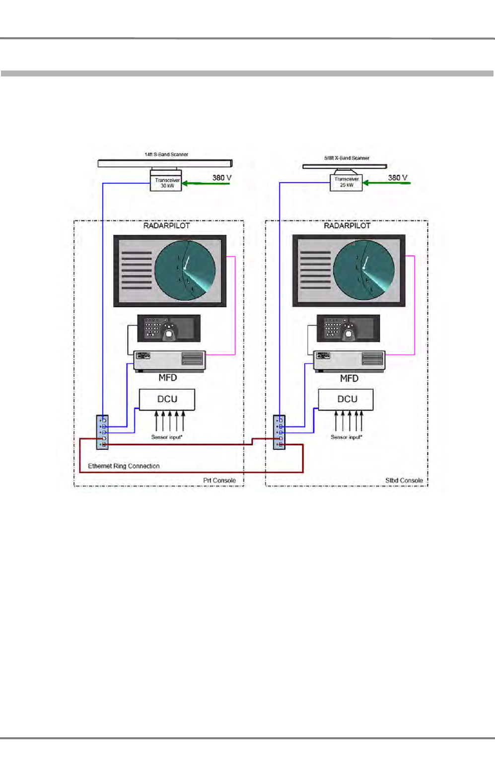
NACOS Platinum
ED 3100 G 110 / 02 (2011-10)
Operating Instructions
A-1 General Information
A RADAR.fm / 10.11.11
A-8
1.3 System Structure and Installation
On the following pages drawings of two typical radar system installations are shown. The system internal
wiring (interconnection) of the Ethernet LAN and other signals is shown on a basic level. For details on
a more technical level, refer to the Technical Manuals.
Fig. A / 1 IMO-Set installation
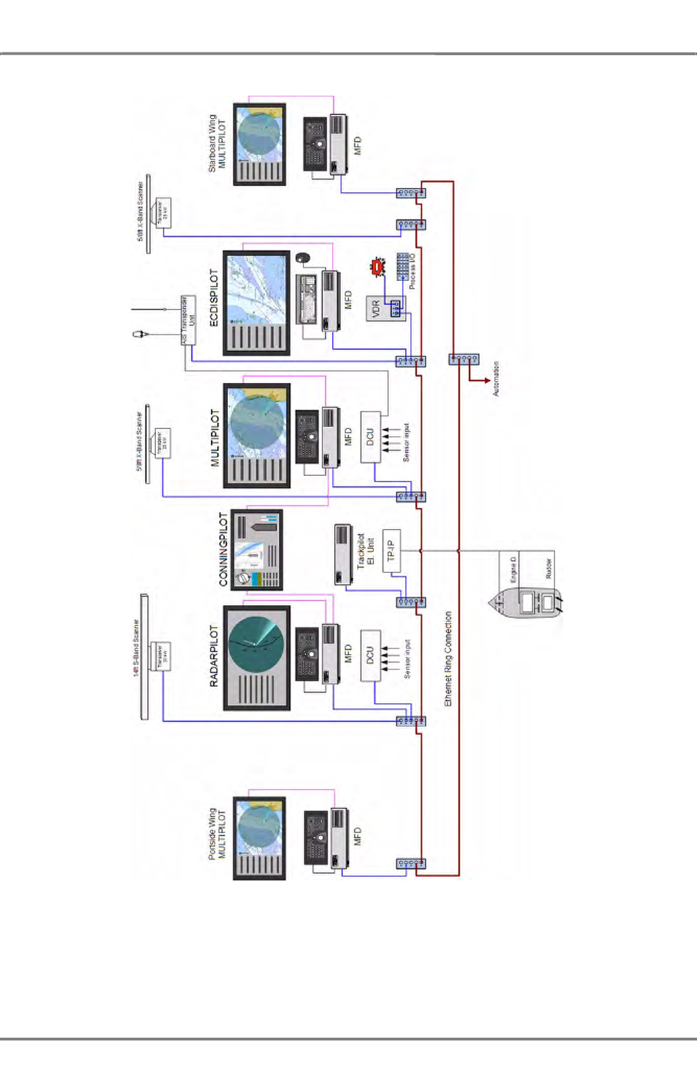
ED 3100 G 110 / 02 (2011-10)
Operating Instructions
A-1 General Information
A RADAR.fm / 10.11.11 A-9
NACOS Platinum
Fig. A / 2 INS-5 Installation
For the INS-5 installation as shown above, consisting of 5 MFD plus Conning Display, additional compo-
nents of NACOS Platinum are neccessary in order to form a redundant, approved ship control system.
See the appropriate chapters of the mentioned components for further information.

NACOS Platinum
ED 3100 G 110 / 02 (2011-10)
Operating Instructions
A-1 General Information
A RADAR.fm / 10.11.11
A-10
Safeguards
The following table gives an overview about the failure modes and the respective system status as well
as possible measures supporting maximum system availability.
Table A / 3 RADAR Failure Modes
As shown in the above table in case of an installation with two or more radar systems each system is
working independently from the other one, a failure in one system does not affect the operation of the
other systems. Each system can work as stand-alone radar without changing any configuration settings.
Failure description Status Measure and Result
Antenna Unit (antenna, gearbox or
transceiver) inoperable or defective This antenna / trans-
ceiver cannot be selected
by any MFD any more
RADAR operation with all other
installed Antenna Units is still avail-
able
Display Electronics (MFD-PC) inoperable
or defective One of two (or more)
radar indicators is not
available
Operate X- or S- Band radar via the
secondary or any other still available
MFD
Display Monitor inoperable or defective
RADAR Keyboard inoperable or defective RADAR indicator remains
available Operate the MFD with on screen
commands and Track ball only; full
operating level is available
Trackball inoperable or defective Limited basic radar operation via the
keyboard remains available
Network Switch or its power supply
defective RADAR indicator and
connected transceiver are
not available
Operate another X- or S- Band radar
via the secondary or any other still
available MFD
Sensor Interface, i.e. Data Processing
Unit (DPU), Data Communication Unit
(DCU) or its power supply defective
All radar indicators and
transceivers remain avail-
able
System automatically activates the
secondary DPU or DCU, the main
navigation sensors (for HDG, SOG,
POSN) remain available.
In a double installation, one of the
transceivers is inoperable or defective The transceiver is not
available The remaining transceiver 1) can be
set as slave on the second indicator;
picture is visible at both indicators.
1) If one of the sensor signals is missing, that navigation data are derived from one of the other sensors
as far as possible, either automatically or manually. For details please refer to chapterSee chapter III
- 3.2 on page 33
In a double installation, one of the MFDs
is inoperable or defective The system cannot be
controlled by this MFD
any longer
Both transceivers can be controlled
with the remaining MFD unit; both
radar pictures can be observed sepa-
rately
In a double installation, "No RADAR
Video" alarm is shown The actual transceiver is
not available 2)
2) Transmission of the radar video from a connected transceiver to the MFD is monitored continuously.
If the connection to the transceiver is disturbed or completely lost, the respective alarm messages
describing the reason for the fault are given (See chapter A - 7.15 on page A-81 for details). If the refresh of
the radar video is not possible, the alarm No RADAR Video is issued; the video in the PPI is cleared and will
no longer be updated.
Switch to the remaining transceiver
In a multiple transceiver installation,
one of the transceivers is inoperable or
defective
The transceiver is not
available Remaining transceivers can be set as
slave on one of the other indicators,
picture is visible on all indicators.
In a multiple transceiver installation,
one of the MFDs is inoperable or defec-
tive
The system cannot be
controlled by this MFD
any longer
All remaining transceivers can be
controlled with the remaining indi-
cator electronics units, all radar
pictures can be observed separately.
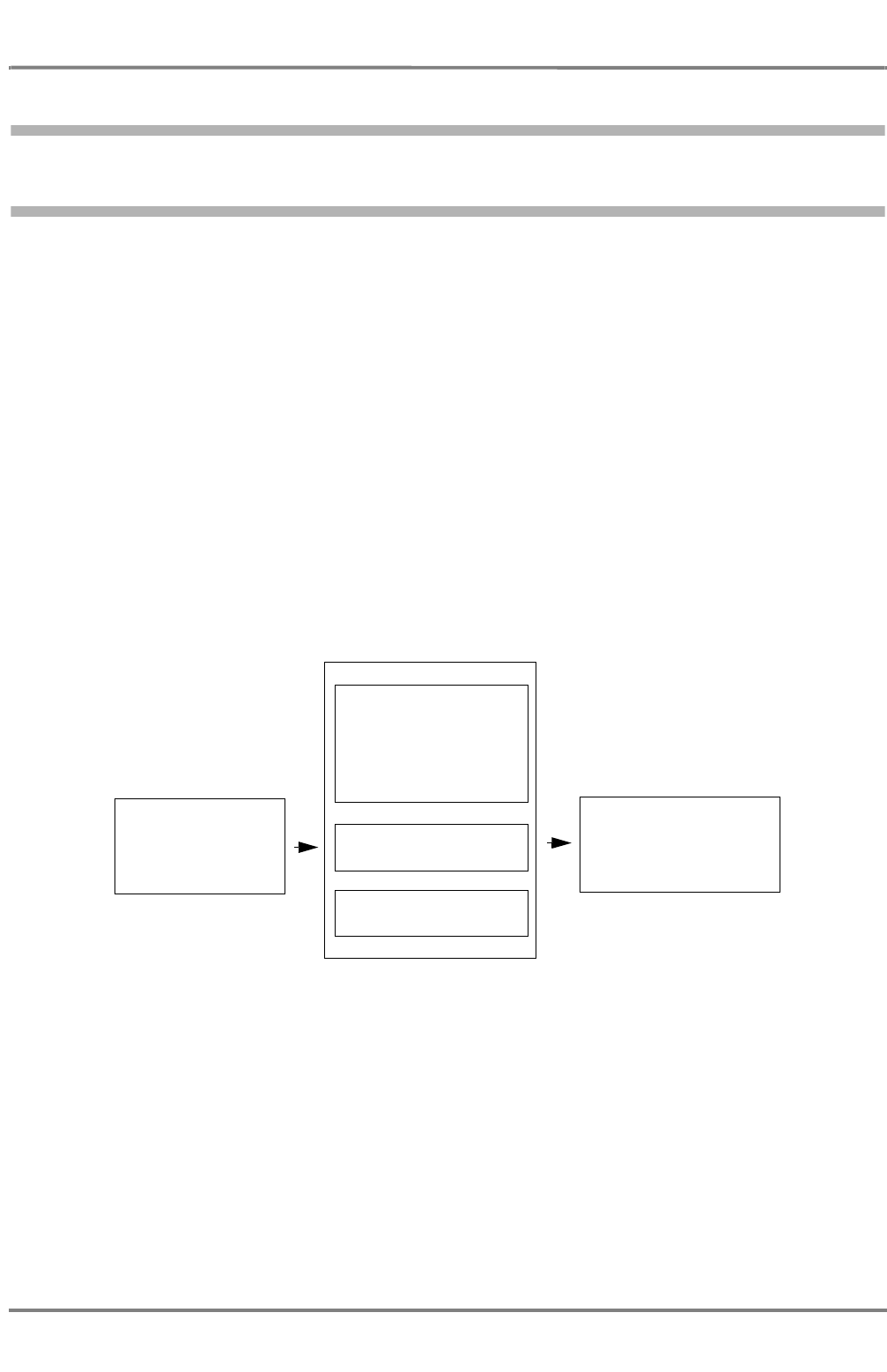
ED 3100 G 110 / 02 (2011-10)
Operating Instructions
A-1 General Information
A RADAR.fm / 10.11.11 A-11
NACOS Platinum
1.4 Basics / Evaluation of the RADAR Video
1.4.1 Basics of the Evaluation of RADAR Video in Platinum Series
Generally, the echo data received by the transceiver can be amplified, attenuated or filtered in order to
enhance the display of desired data like targets. The main intention of the signal processing is the clear
and unmistakeable display of radar targets and the suppression of unwanted echoes like sea clutter,
rain clutter or interferences.
Amplification, attenuation or filtering is done in several ways, with continuosly or digitally working filters.
(Some can be set from 0% to 100%, others can only be switched on or off).
Further on, echo data with the same azimuth delivered from one or more radar pulses („sweep-to-sweep-
data“) can be processed or data from one or more antenna turnarounds („scan-to-scan-data“) can be
evaluated.
The amplitudes of echoes can be evaluated in order to determine whether the echoes are targets or
noise, or the correlation of sweep-to-sweep or scan-to-scan data can be used to enhance the radar
picture:
Table A / 4 Scheme of RADAR Video Evaluation
Amplitudes are influenced for example by the Gain and Sea settings, correlation is done amongst others
by the Enhance functions.
In the following, the different filters, their basic techniques and advantages or limitations are described
in the sequence they appear on the screen.
Raw RADAR Data
Processing
Amplification
Attenuation
Filtered RADAR Data
Amplitude Treatment
Correlative Treatment
Sweep-to-sweep
Scan-to-scan
NACOS Platinum
ED 3100 G 110 / 02 (2011-10)
Operating Instructions
A-1 General Information
A RADAR.fm / 10.11.11
A-12
Short Pulse/Long Pulse is available for any range of the radar. The internal pulse length changes with
respect to the selected range automatically. For detailed information on the pulse lengths for any range,
please refer to the table in section 1.4.2 of the Operating Instructions.
The default setting for the pulse length should be Short Pulse. A longer pulse has a higher energy, but
not a higher amplitude. Thus, it delivers stronger echoes. It is allowed to switch between the two pulse
lengths at any time.
If target enhancement or any other filtering methods are active, the stronger echoes are processed by
the filters and are able to improve a weak radar picture.
The Tune function can be set manually or automatically. Tune influences the center frequency of the
entire radar echo evaluation process. For the adaption of Tune, no radar echoes are needed and inter-
ference from other radar devices is suppressed so that automatic tuning (AFC) has the best results and
should be used as default. An optimum tuning is not only important for a clear visual display of the
targets on the video but is also a necessary prerequisite for the ARPA functions.
Gain setting influences the amplitudes of all echoes and works like an amplifier that makes it possible
to enhance all echoes and noise in the same way in order to get a better picture. But, as said before,
also the noise will be amplified and can disturb the clear display of targets. Gain should in any case be
set in such a way that slight noise is always visible.
Rain can be set to Off or Low, Medium and High. With an optimal setting of Rain only the boundary
of the rainy area facing towards the transceiver is displayed and echoes within or behind the rainy area
will be displayed if their echo is still strong enough after having been filtered. Weak echoes will not be
displayed if their echo is too small after the signal has been processed by the filter.
For each setting, a correlative signal processing takes place and filters out the noise of the rainfall.
Echoes which are strong enough will be displayed, others may disappear.
Sea can be set to manual or automatic mode. In manual mode, its setting influences the amplitudes of
the radar echoes in such a way that it attenuates echoes close to the antenna very much and that it
attenuates echoes which are more distant to it only very little. Due to the fact that the distance of a
target is represented by the time its echo needs to return to the antenna, this is called „sensitivity-time-
control“ (STC). Nevertheless, echoes which are as strong as the unwanted reflections of the sea may be
suppressed and not visible, or they may appear and disappear, depending on how strong the
surrounding unwanted reflections are.
In automatic mode, a fixed, approved value for the Sea filter is set. Advantages or limitations to the
effect are the same as in manual mode.
In the case of heavy rain, snow and hail, it can be expected that, even if the setting is
correct, radar targets which only produce weak reflections - especially targets situated
behind a strong rain front - will remain undetected. Such targets can appear suddenly
when leaving the rainy area.
ED 3100 G 110 / 02 (2011-10)
Operating Instructions
A-1 General Information
A RADAR.fm / 10.11.11 A-13
NACOS Platinum
Simultaneous operation of Rain and Sea
Enhance combines an adaptive STC, an additional correlative filter and a so-called „target enhancement“
in four selectable steps. See also the table on page A-14.
Definitions:
Adaptive STC is a second STC that is derived from the medium value of the echoes of the last sweeps.
It is added to the manual STC and is able to suppress clutter.
The correlative filter works in scan to scan mode or over several scans respectively with its parameters
relative to the selected range. In large ranges, the correlation filter will need several scans until an effect
to the picture is visible, in smaller ranges the effect of the filter is faster. It is also able to suppress noise.
Target enhancement is used to display even very small or weak targets. For example, if an echo is
this small that it only lights up one pixel of the screen, it could be overseen or regarded as noise or
clutter. Target enhancement makes it a little bigger, so that is is better to discover among the more
dynamic clutter or noise. With this enhanced target, the correlation filter can work much more precisely.
In order to get information of when to use which of the four levels of the Enhance function, please
refer to the user manual. See chapter 5.2.4 on page A-43.
In the case that anticlutter sea value is set too large, weak targets can be lost, especially
at close range. If the sea is very rough, it can be expected that radar targets which only
produce weak reflections will remain undetected, even if the setting is correct.
In case that Rain and Sea are operated simultaneously, especially in very rough weather
conditions, the detection of radar targets may fail even if all settings are correct, because
the sum of clutter (reflections of sea and rain) is as high as or even higher than the reflec-
tion of targets.
When the Enhance function is running, the scan-to-scan correlation might have the result
that small, fast-moving targets or Racon codes are displayed with reduced intensity or
might be suppressed.

NACOS Platinum
ED 3100 G 110 / 02 (2011-10)
Operating Instructions
A-1 General Information
A RADAR.fm / 10.11.11
A-14
In the table below the settings of the respective filters are described:
Table A / 5 Qualitative description of Enhance levels
Interference Rejection is a means to suppress interferences caused by other radars working on the
same frequency. For example, if two radars of the same kind operate very close to each other and the
PRF and signal frequency are similar or equal, the radars will influence each other with their pulses or
echoes. Circles or coils will appear on the PPI. With Interference Rejection on, most of those effects
will be eliminated by a filter that is able to detect those special signals. Targets will not be suppressed.
See also
A-Distortions of the RADAR Video
in section 1.4.3.
Video Emphasis can be used to increase the detection of targets of the radar. Very strong echoes will
be shown in orange colour. It can help to decide whether an echo is one or two combined objects. For
example, without VE the echo is only a large yellow spot, with VE switched on it is visible that the yellow
spot contains 2 smaller orange dots, it can be decided that there is a structure in the yellow spot or that
there are two echoes very close to each other. The display of targets on the PPI will be improved, targets
will not get lost if VE is switched off. Also structures in land areas or in rainclouds or seaclutter can be
made more visible by the VE function, for instance a light house on a land area or buoys with only a
short distance to the land, whose echoes would normally melt into the ones of the land.
1.4.2 Achievable RADAR Range
The theoretically achievable radar range limited by the curvature of the earth depends on the height
of the antenna above the water surface and the height of the target, and is applicable under normal
atmospheric conditions - see the following table.
Table A / 6 Achievable RADAR Range
Whether radar targets can be detected up to this theoretical range, even with optimum video setting,
depends not only on the atmospheric conditions but also on the characteristics of the target:
Enhance Off Low Medium High
Adaptive STC no no yes, but small yes, medium
value
Correlation no yes, with short time-
constant yes, longer time-
constant than
„LOW“
yes, longer time-
constant than
„MEDIUM“
Target
enhancement very little, small
targets just visible little medium high
Antenna Height
Above Water Surface
Theoretically Achievable RADAR Range
at a Target Height of
1 m 3 m 10 m 30 m 100 m 300 m 1000
m
8 m 9 NM 12 NM 13 NM 18 NM 28 NM 44 NM 76 NM
15 m 11 NM 13 NM 16 NM 21 NM 31 NM 47 NM 79 NM
30 m 12 NM 16 NM 19 NM 23 NM 34 NM 50 NM 82 NM
ED 3100 G 110 / 02 (2011-10)
Operating Instructions
A-1 General Information
A RADAR.fm / 10.11.11 A-15
NACOS Platinum
- Large targets with good reflection characteristics produce strong echo signals and are displayed with
corresponding clarity on the screen.
- Smaller targets situated in the shadow of large objects are not illuminated by the radar pulses and
are therefore not displayed.
- Flat coasts have an unfavourable reflection cross-section and cannot be recognized until they have
been approached more closely. On the other e , high coastlines and mountainous regions further
inland are recognised at a very early stage.
- In the coastal approaches, the tide rip lines and surf areas are displayed similarly to coastlines.
However, this rather irritating display can be a valuable orientation aid for the coastal navigator.
- The reflections of radar waves from ice depend largely on the surface structure of the areas illumi-
nated by the radar. Rough and jagged surfaces produce good echo displays, whereas smoothly
frozen-over surfaces, rounded surfaces and surfaces at an oblique angle generally reflect the trans-
mitted pulses away from the ship. Thus, for example, the echo display of large icebergs can fluc-
tuate extremely severely, depending on the existing aspect.
- The detection of low-lying blocks of ice (growlers) probably presents the greatest uncertainty:
1.4.3 Distortions of the RADAR Video
Because of the physical characteristics of the radar principle used, the video displayed does not corre-
spond exactly to the position and form of the reflecting target. A distinction must be drawn between
radial distortions (in the direction of the target) and azimuthal distortions (perpendicular to the target
direction) - see figure on next page.
Radial Distortions
Radial distortions in the direction of transmission are caused by the fact that a target reflects the trans-
mitted pulse for as long as the pulse is moving past the target 1). Thus, radial lengthening depending on
the pulse duration occurs on the screen. In the case of range measurements, it must be noted that the
echo edge facing own ship corresponds to the true front edge of the target.
If there are several targets behind one another with small (radial) distances between them, they are
shown separately on the screen if, and only if, their distance apart is so large that the radial lengthened
echoes do not overlap.
Azimuthal Distortions
Azimuthal distortions are caused by the width of the beam radiated by the antenna. A point target
appears wider the further away it is. At a distance of 10 NM with a horizontal antenna-beamwidth of
1.5°, an individual target is displayed as an arc with a length of 480 m. Because of this effect, individual
targets situated beside one another can merge to form a single target.
Even if the anticlutter facilities are operated carefully, the echoes from growlers
can no longer be definitely identified if moderate disturbances from the sea
surface are present.
1) The pulse length setting Long Pulse thus generates larger radial distortions than Short Pulse.
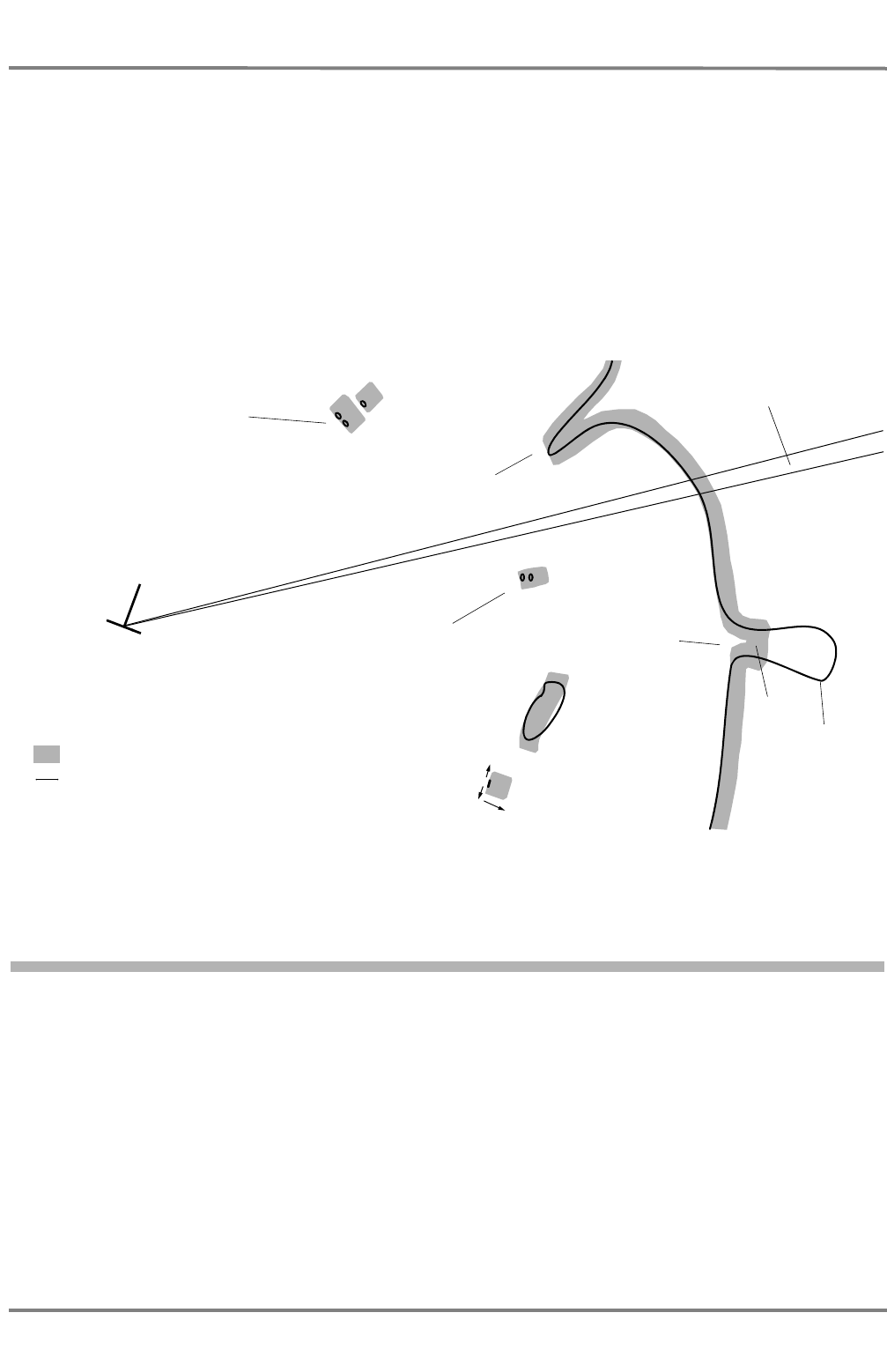
NACOS Platinum
ED 3100 G 110 / 02 (2011-10)
Operating Instructions
A-1 General Information
A RADAR.fm / 10.11.11
A-16
☞ Not only individual targets but also small spits of land aligned in the radial direction appear wider
than they really are, and radially oriented entrances appear narrower than in reality.As a result of
azimuthal distortions and/or changes in the target position, the radar centroid of a target can
change, especially at short range. In the case of a target being tracked, this can lead to a sudden
change in the displayed vector.
In addition to these undesirable azimuthal distortions, targets can also be deliberately widened with
increasing distance, so that narrow, close-range targets too can be seen clearly. This function is used in
the Enhance modes Medium and High. It ensures that the azimuthal distortion corresponds to the
radial distortion over a wide range of distances. Because the radial distortion depends on the pulse
length, the targets are displayed particularly large by the selection of Long Pulse.
Fig. A / 3 Radial and azimuthal distortions of the radar video
1.4.4 Undesirable Echo Displays and Effects
Disturbances of the radar video are caused by
- meteorological processes,
- reflections from the sea surface,
- radar signals from other transmitters,
- false echo displays,
- sectors of reduced radar visibility,
- superrefraction and subrefraction.
Two adjacent targets merge to
form one radar echo (azimuthal
distortion)
Radial distortion
Azimuthal distortion
RADAR video
Actual size of the target
Two targets behind one
another merge to form one
radar echo (radial distortion)
Width of the beam radiated
by the antenna
A spit of land is displayed wider
An entrance is
displayed narrower or
not at all
Land contour
RADAR video

ED 3100 G 110 / 02 (2011-10)
Operating Instructions
A-1 General Information
A RADAR.fm / 10.11.11 A-17
NACOS Platinum
Influences of Meteorological Processes
The influence of meteorological phenomena such as fog, rain, snow or hail on the radar video increases
with the size of the droplets in relation to the radar wavelength, and with the density of the droplets.
The shorter-wave X-Band radar (with a wavelength of 3 cm) is therefore generally impaired more
severely by meteorological influences than is the longer-wave S-Band radar (10 cm wavelength).
The following table describes the influences of rain and the influences on the radar:
Table A / 7 Influences of Meteorological Processes
In general, it is advisable not to use long pulse in rainy conditions and it is better to use the S-band
radar rather than the X-band. If no S-band radar is available, it must be considered that X-band radars
lose 50% of their coverage in heavy rains.
X-Band RADAR
Even in the X-Band radar, fog causes practically no disturbances, whereas precipitations with larger drop-
lets attenuate the transmitted radar pulses and thus weaken to a greater or lesser extent the display of
targets situated behind extensive areas of precipitation. Furthermore, throughout their entire extent, rain,
snow and hail reflect part of the transmitted energy and produce echoes in the form of milky areas in
the radar video (backscatter).
Because of the very different signal structures of useful targets and rain areas, rain clutter can be notice-
ably reduced by the rain clutter suppression function.
Reduction of target detection S-Band,
short pulse S-Band;
long pulse X-Band,
short pulse X-Band,
long pulse
Rain, 4mm/h, close range < 5nm Slightly Severely Slightly Severely
Rain, 4mm/h, medium range Nearly none Up to half Slightly Severely
Rain, 4mm/h, long range > 10nm Nearly none Slightly Slightly Severely
Rain, 16mm/h, close range < 5nm Slightly Severely Up to half Severely
Rain, 16mm/h, medium range Nearly none Severely Up to half Severely
Rain, 16mm/h, long range > 10nm Nearly none Severely Up to half Up to half
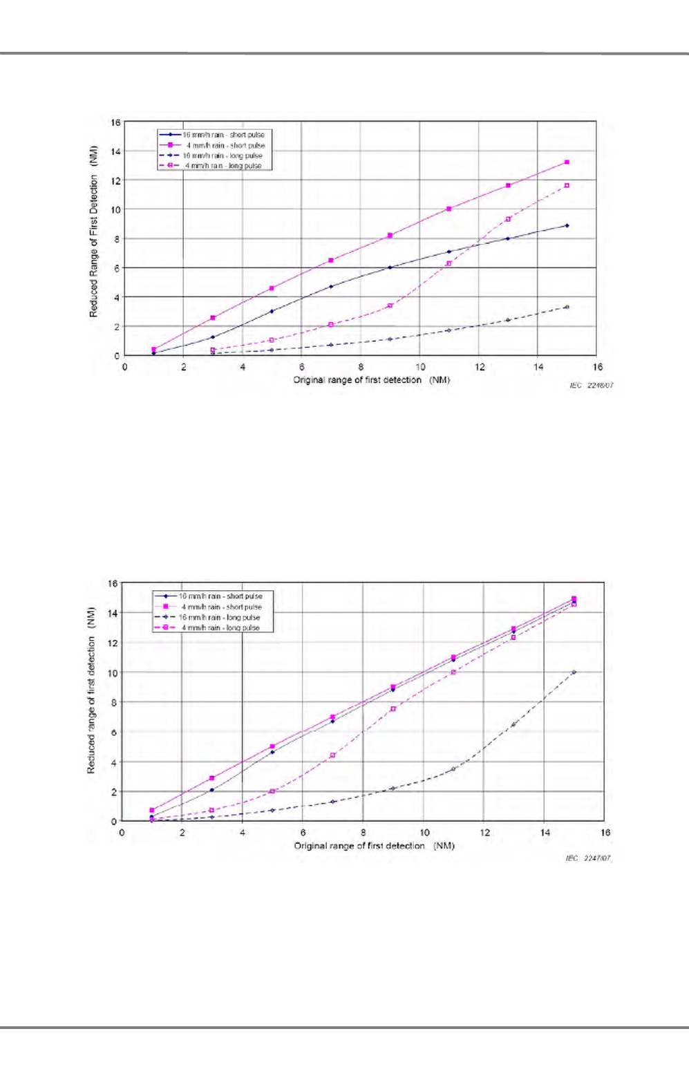
NACOS Platinum
ED 3100 G 110 / 02 (2011-10)
Operating Instructions
A-1 General Information
A RADAR.fm / 10.11.11
A-18
In the case of strong, extended areas of rain, the losses become so great that the achievable range is
reduced very severely. Useful targets might be completely concealed.
Fig. A / 4 Reduced Range of First Detection in Dependance or Precipitation in X-Band
S-Band RADAR
The S-Band radar „sees“ through the rain with practically no attenuation losses, and even detects targets
in and behind a rain area. The echo signals caused by the rain are only displayed weakly. Similar behav-
iour is exhibited in the case of hail and snow.
In this case too, unusually heavy rain can reduce the achievable ranges and thus cause sudden loss of
targets.
Fig. A / 5 Reduced Range of First Detection in Dependance or Precipitation in S-Band

ED 3100 G 110 / 02 (2011-10)
Operating Instructions
A-1 General Information
A RADAR.fm / 10.11.11 A-19
NACOS Platinum
Reflections from the Sea Surface
Clutter echoes from the surface of the sea can be recognised from the fact that a mostly circular but
eccentric area displaced in the wind direction and having non-uniform brightness is formed around the
own ship symbol (sea clutter). These echoes make targets in this region more difficult to detect and
track, but they have no effect on the display of targets situated behind the reflection zone.
These disturbances are more severe in the case of a radar antenna mounted high up than for one
mounted lower down. The area covered by these disturbances increases with increasing sea state, and
is increased particularly by steeper waves.
With the aid of the sea clutter suppression function, the disturbance echoes described above can be
reduced. However, since this also weakens the display of targets and because the target might not be
displayed with every revolution of the antenna, maximum concentration by the observer is necessary. In
the case of automatic target tracking, the sea clutter suppression function can lead to the loss of targets
due to the attenuation of the signals.
Disturbances Caused by Other RADARs
Transmissions from other radars working in the same electrical frequency band occur as disturbances in
the form of small points or dashes. These move in rapid succession along straight or curved tracks to
the centre of the screen or in the opposite direction.
These disturbances appear particularly clearly at the larger range settings, but they impede radar obser-
vation to an insignificant extent only. They can be almost completely eliminated by means of the Inter-
ference Rejection function which is activated automatically on the Platinum RADAR but which can be
switched off if required.
False or Indirect Echo Displays
False or indirect echo displays ("ghost echoes") occur as a result of reflection of the radar pulses by the
ship's own superstructures of all kinds and by nearby objects that reflect very well. Therefore, a typical
feature of these echoes is that they appear at the bearing of the reflecting surface, regardless of the real
position of the targets.
When two ships pass one another on parallel courses, multiple echoes can often be observed as a result
of pulses reflected to and from several times between the ships' sides. On the screen, a series of equis-
paced echo displays of decreasing intensity appears at the bearing of the object.
Sectors of Reduced RADAR Visibility
Sectors of reduced radar visibility occur as a result of own ship's superstructures which impair and
prevent rectilinear propagation of the radar pulses. Theoretical determination of the geometry of these
sectors and of their influence on the display of targets is possible to an inadequate extent only. An effec-
tive practical method consists of determining the shadow sectors against the background of disturbance
signals from the sea surface (sea clutter).
Superrefraction - Subrefraction
If the normal refraction gradient for the radar wave in the maritime boundary layer of the atmosphere
is changed by external influences, subrefraction occurs when the transmitted beam is bent upwards away
from the earth's surface, and superrefraction occurs when the transmitted beam is bent down towards
the earth's surface.
In the case of superrefraction, false echoes of targets outside the set range of measurement can occur:
the echo of a transmitted pulse is not received within the set range but during the next transmit cycle
or by the one after that. The resulting ghost echoes can occur at any position. Since the position of ghost
echoes depends on the pulse repetition frequency, ghost echoes can be recognised as such by switching
over the pulse length or the range on the master radar.

NACOS Platinum
ED 3100 G 110 / 02 (2011-10)
Operating Instructions
A-1 General Information
A RADAR.fm / 10.11.11
A-20
☞ Every pulse length has a particular pulse repetition frequency assigned to it; therefore, when the
pulse length or range is changed, the repetition frequency changes too (See chapter 1.4.8 on page
A-23).
1.4.5 RADAR Setting for the Display of Racon Codes
The code of Racons consists of a radially arranged dash-dot code which begins in the radar video a short
distance behind the beacon position. By means of different codes described in the Lists of Lights, the
approach points equipped with Racons can be clearly identified.
Most Racons transmit in the X-Band, but there are some Racons installed which transmit in the S-Band.
The majority of Racons change their transmission frequency slowly throughout the entire frequency
band, and so they are not received in every revolution of the antenna.
For the setting of the radar, the same basic principles are applicable as for SART detection (See chapter
1.4.7 on page A-21)
1.4.6 RADAR Settings for Target Enhancer Detection
The target enhancer is an active device on a target vessel which transmits an X-band pulse upon recep-
tion of any X-band radar signal. The pulse length of this secondary radar pulse does not typically reflect
the size of the actual target vessel but is fixed. In general this kind of equipment is used on small boats
which have not a significant radar profile like pleasure boats or wooden boats or lifeboats. There are no
special settings required for detection of target enhancers. They are just visualized like a very well
reflecting target.

ED 3100 G 110 / 02 (2011-10)
Operating Instructions
A-1 General Information
A RADAR.fm / 10.11.11 A-21
NACOS Platinum
1.4.7 RADAR Setting for SART Detection (X-Band only)
The information needed for reliable detection of SART's is described in IMO Circular 161. The content of
that paper is reproduced on the following pages.
ANNEX
OPERATION OF MARINE RADAR FOR SART DETECTION
WARNING: A SART will only respond to an X-Band (3 cm) radar. It will not be seen on
an S-Band (10 cm) radar.
Introduction
l. A Search and Rescue Transponder (SART) may be triggered by any X-Band (3 cm)
radar within a range of approximately 8 n.miles. Each radar pulse received causes it to
transmit a response which is swept repetitively across the complete radar frequency band.
When interrogated, it first sweeps rapidly (0.4 μsec) through the band before beginning a
relatively slow sweep (7.5 μsec) through the band back to the starting frequency. This
process is repeated for a total of twelve complete cycles. At some point in each sweep, the
SART frequency will match that of the interrogating radar and be within the pass band of
the radar receiver. If the SART is within range, the frequency match during each of the 12
slow sweeps will produce a response on the radar display, thus a line of 12 dots equally
spaced by about 0.64 n.miles will be shown.
2. When the range to the SART is reduced to about 1 n.mile, the radar display may show
also the 12 responses generated during the fast sweeps. These additional dot responses,
which also are equally spaced by 0.64 n.miles, will be interspersed with the original line
of 12 dots. They will appear slightly weaker and smaller than the original dots.
RADAR Range Scale
3. When looking for a SART it is preferable to use either the 6 or 12 n.mile range scale.
This is because the total displayed length of the SART response of 12 (or 24) dots may
extend approximately 9.5 n.miles beyond the position of the SART and it is necessary to
see a number of response dots to distinguish the SART from other responses.
SART Range Errors
4. When responses from only the 12 low frequency sweeps are visible (when the SART
is at a range greater than about 1 n.mile), the position at which the first dot is displayed
may be as much as 0.64 n.mile beyond the true position of the SART. When the range
closes so that the fast sweep responses are seen also, the first of these will be no more than
150 metres beyond the true position.
RADAR Bandwidth
5. This is normally matched to the radar pulse length and is usually switched with the
range scale and the associated pulse length. Narrow bandwidths of 3-5 MHz are used with
long pulses on long range scales and wide bandwidths of 10-25 MHz with short pulses on
short ranges.
6. A radar bandwidth of less than 5 MHz will attenuate the SART signal slightly, so it
is preferable to use a medium bandwidth to ensure optimum detection of the SART. The
RADAR Operating Manual should be consulted about the particular radar parameters and
bandwidth selection.
Note about item 6: The bandwidth of the radar is not less than 5 MHz. Therefore, the setting described here is not necessary

NACOS Platinum
ED 3100 G 110 / 02 (2011-10)
Operating Instructions
A-1 General Information
A RADAR.fm / 10.11.11
A-22
RADAR Side Lobes
7. As the SART is approached, side lobes from the radar antenna may show the SART
responses as a series of arcs or concentric rings. These can be removed by the use of the
anti-clutter sea control although it may be operationally useful to observe the side lobes as
they may be easier to detect in clutter conditions and also they will confirm that the SART
is near to own ship.
Detuning the RADAR
8. To increase the visibility of the SART in clutter conditions, the radar may be detuned
to reduce the clutter without reducing the SART response. RADARs with automatic
frequency control may not permit manual detune of the equipment. Care should be taken
in operating the radar in the detuned condition as other wanted navigational and anti-colli-
sion information may be removed. The tuning should be returned to normal operation as
soon as possible.
Gain
9. For maximum range SART detection the normal gain setting for long range detection
should be used i.e., with a light background noise speckle visible.
Anti-Clutter Sea Control
10. For optimum range SART detection this control should be set to the minimum. Care
should be exercised as wanted targets in sea clutter may be obscured. Note also that in
clutter conditions the first few dots of the SART response may not be detectable, irrespec-
tive of the setting of the anti-clutter sea control. In this case, the position of the SART may
be estimated by measuring 9.5 n.miles from the furthest dot back towards own ship.
11. Some sets have automatic/manual anti-clutter sea control facilities. Because the way
in which the automatic sea control functions may vary from one radar manufacturer to
another, the operator is advised to use manual control initially until the SART has been
detected. The effect of the auto sea control on the SART response can then be compared
with manual control.
Anti-Clutter Rain Control
12. This should be used normally (i.e. to break up areas of rain) when trying to detect a
SART response which, being a series of dots, is not affected by the action of the anti-
clutter rain circuitry. Note that Racon responses, which are often in the form of a long
flash, will be affected by the use of this control.
13. Some sets have automatic/manual anti-clutter rain control facilities. Because the way
in which the automatic rain control functions may vary from one radar manufacturer to
another, the operator is advised to use manual control initially until the SART has been
detected. The effect of the auto rain control on the SART response can then be compared
with manual control.
Note:
The automatic rain and sea clutter controls may be combined in a single ’auto-clutter’
control, in which case the operator is advised to use the manual controls initially until the
SART has been detected, before assessing the effect of auto.

ED 3100 G 110 / 02 (2011-10)
Operating Instructions
A-1 General Information
A RADAR.fm / 10.11.11 A-23
NACOS Platinum
1.4.8 Transmission formats
To optimise detection performance for the different weather conditions, the radar provides different pulse
lengths and repetition rates.
The pulse repetition rates in relation to the range and the pulse length are shown in the following table:
Table A / 8 Transmission formats
Scanner rotation frequency 23/28 rpm
Range (NM) 1)
1) All values of the 0.25 NM range are also valid for the 250 m/500 m ranges
0.25 0.50 0.75 1.5 3 6 12 24 48 96
Short pulse
Pulse length (µs) 0.08 0.15 0.30 0.50 1.00 2)(
0.90 3)
2) 12.5 kW X-Band Transceiver
3) 25 kW X-Band and 30 kW S-Band Transceiver
PRF (Hz) 2000 1000 500
Long pulse
Pulse length (µs) 0.15 0.30 0.50 1.00 2)
0.90 3)
PRF (Hz) 1000 500
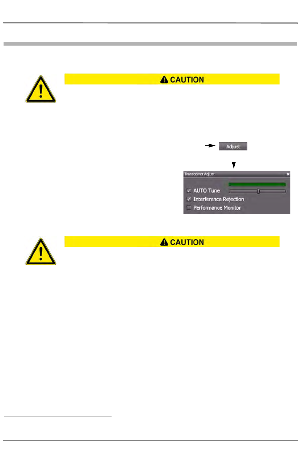
NACOS Platinum
ED 3100 G 110 / 02 (2011-10)
Operating Instructions
A-1 General Information
A RADAR.fm / 10.11.11
A-24
1.5 Basic setting of the RADAR Video
So that radar targets can be detected with certainty, an optimum setting of the radar video is of funda-
mental importance.
In the following, there is a description of how to set the video of a radar correctly on the master indi-
cator. Only after these settings have been made on the master indicator can activated slave indicators
too be set in the same way (parameters that cannot be set on slave indicators are pointed out). 1)
1. Select the 12 NM display range.Click on
the Adjust control. The Transceiver
Adjust window is opened, settings can
be made.
2. Tuning (adjustment of the frequency) (can be set on the master indicator only)
Automatic tuning: Select the Auto checkbox. This is the default setting.
The slider is moved automatically by the system into the position of the optimal value.
☞ If two X-Band or two S-Band systems are being operated simultaneously, disturbance of automatic
tuning might occur (if it is being used). In such cases, manual tuning is appropriate.
Manual tuning: Clear the Auto checkbox and use the slider to perform manual tuning. The green indi-
cator bar above the slider corresponds to the amplitude with which the input signal is available for signal
processing. Observe more than one antenna rotation to find the maximum.
Especially in the case of heavy rain and/or a rough sea, it is essential that the setting be
adapted by trained personnel so that it is suitable for the situation.
1) In ECDIS mode, only those settings are possible that can be performed with the radar keyboard (if a radar keyboard is installed).
An optimum tuning is not only important for a clear visual display of the targets on the
video but is also a necessary prerequisite for the ARPA functions.
Click
(Example)
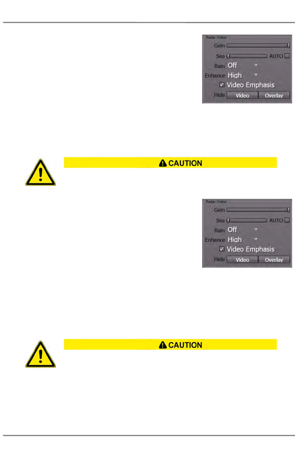
ED 3100 G 110 / 02 (2011-10)
Operating Instructions
A-1 General Information
A RADAR.fm / 10.11.11 A-25
NACOS Platinum
3. Gain (input amplification)
Switch off the Enhance function. Use the Gain slider, and
increase the value with the trackball until slight noise is
visible on the PPI. Then reduce the value a little until the
noise has just disappeared, but not more. Switch on the
Enhance function again and, if necessary, increase the gain
a little (up to 100% for a favourable sea state).
☞ With the Enhance function activated, the change in gain
only has an effect after several revolutions of the antenna.
☞ On the keyboard, manual tuning is performed by turning the Gain knob.
4. Select the desired display range.
5. Anticlutter Sea (sea clutter suppression)
With anticlutter sea, the input amplification at close range is reduced depending on the distance.
Manual suppression of sea clutter: Use the Sea slider to
set the value so that the clutter caused by a rough sea is as
weak as possible but radar targets are still clearly visible.
☞ If the Enhance function is switched on, the radar requires
several revolutions of the antenna in order to adjust itself to
changed anticlutter sea values. Therefore, any large changes
should only be made slowly (step by step).
☞ On the keyboard, manual tuning is performed by turning the
Sea knob.
Automatic suppression of sea clutter: Select the Auto checkbox behind Sea.
☞ The automatic anticlutter sea function has the advantage that the clutter values taken into account
in the upwind direction are different from those taken into account in the downwind direction.To
check the display of very small target-echoes, it is necessary to switch over to manual operation.
See chapter 1.4.1 on page A-11 for further description of this mode and its specifics.
6. Anticlutter Rain (suppression of rain clutter)
The suppression of rain clutter can be set to Off or three values: Low, Medium or High.
If the value is set to Low or Medium, the filter works with pre-set coefficients just like in manual
mode, if the value is set to High, the suppression is operated with correlative coefficients like in
automatic mode.
In the case of anticlutter sea values that are too large, weak targets can be lost, especially
at close range.If the sea is very rough, it can be expected that radar targets which only
produce weak reflections will remain undetected, even if the setting is correct.
In the case of heavy rain, snow and hail, it can be expected that, even if the setting is
correct, radar targets which only produce weak reflections - especially targets situated
behind a strong rain front - will remain undetected. Such targets can appear suddenly
when leaving the rainy area.
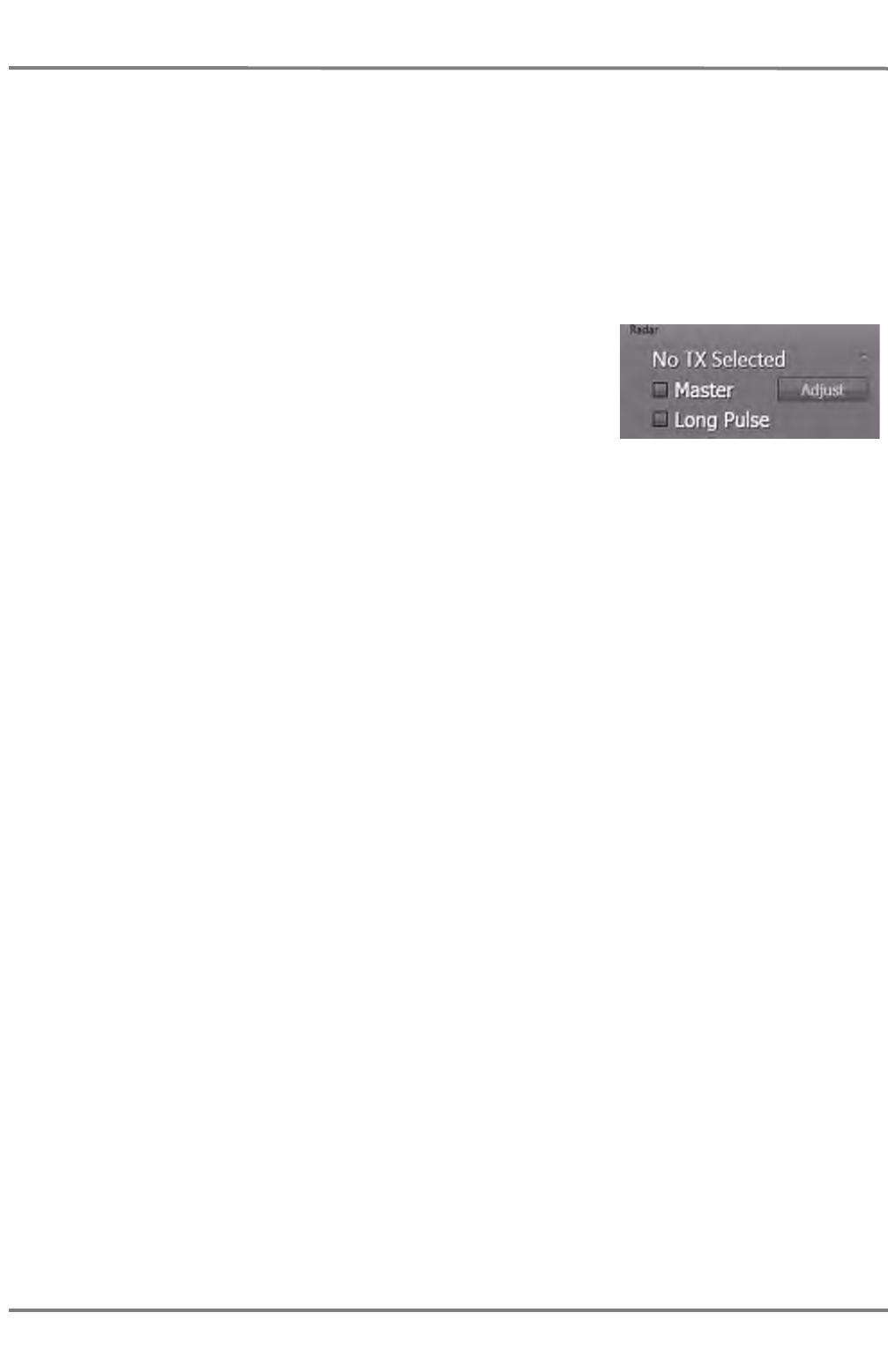
NACOS Platinum
ED 3100 G 110 / 02 (2011-10)
Operating Instructions
A-1 General Information
A RADAR.fm / 10.11.11
A-26
The anticlutter rain function has the advantage that it takes place individually for regions with widely
differing precipitation. A manual rain clutter control is not available.
Choose one of the the values so that the boundary of the rainy area is clearly visible and the clutter
in the region behind it is as weak as possible. However, radar targets should still be clearly visible.
See chapter 1.4.1 on page A-11 for further description of this mode and its specifics.
7. Video Emphasis
Strong video signals can be accentuated optically by switching on the Video Emphasis function. This
function is switched on and off by selecting or clearing the Video Emphasis checkbox.
8. Pulse length
After switch-over to a smaller display range, check whether a
better display is obtained by switching to a different pulse
length. Switching is done by selecting or clearing the Long
Pulse control.
Orientation values for settings on the open sea
Up to sea state 3 - 4, no rain
Gain 90% - 100%
Anticlutter sea 20%
Anticlutter rain Off
Enhance Medium or High
Interference rejection On
Pulse length SP
Up to sea state 3 - 4, rain medium to heavy
Gain 85% - 95%
Anticlutter sea 20%
Anticlutter rain Medium or High
Enhance Medium or High
Interference rejection On
Pulse length SP or LP
Sea state 6 - 9, with rain
Gain 80% - 90%
Anticlutter sea 30% - 50%
Anticlutter rain Low
Enhance Medium or High
Interference rejection On
Pulse length LP

ED 3100 G 110 / 02 (2011-10)
Operating Instructions
A-1 General Information
A RADAR.fm / 10.11.11 A-27
NACOS Platinum
1.6 RADAR Accuracy
Background
The correct measurement of a target position by radar is determined by the bearing and range accuracy
of the radar system. Both parameters are depending on physics, on installation, and on the ability of the
user to read accurate values from the screen.
As far as the physics is concerned, the accuracy of bearing measurement basically depends on the
narrowness of the radar beam. The radar beam for X-band has a horizontal beam width of 1.5° with the
5 foot antenna and 0.95° with 8 foot antenna. For S-band the corresponding value is 1.8° with 14 foot
antenna. These values describe the 3 dB corners on each side of the beam, where the transmitted power
is half of the centre value. Experience shows, that typically at sea these values are doubled. So the prac-
tical beam width of an 8 foot X-band antenna is about 2°. It provides an echoe with a size of:
-> 6 nm x sin 2° = 387 m
Further on physics is involved with range measurement. It depends on the pulse rate and length which
are determined by the user selected range. To minimize error when measuring the range of a target, put
the target echo at an outer position on the screen by selecting a suitable range.
In terms of installation the bearing is usually taken relative to the ship's heading, and thus, proper
adjustment of the heading line at installation is an important factor in ensuring bearing accuracy.
Finally the user aspect has to be considered. To minimize error when taking the bearing of a target from
screen, put the target echo at an outer position on the screen by selecting again a suitable range.
Results
According to IMO (MSC.192/5.2) the radar system range and bearing accuracy shall be as follows:
• "Range: within 30 m or 1 % of the range scale in use, whichever is greater;
• "Bearing: within 1°
in typical operational and environmental conditions.
A well adjusted 1) Platinum RADARpilot is exceeding these requirements as follows:
• "Range: within 15 m or 0.3 % of the range scale in use, whichever is greater;
• "Bearing: within 0.5°
in typical operational and environmental conditions.
1) in terms of trigger delay and heading line adjustment

NACOS Platinum
ED 3100 G 110 / 02 (2011-10)
Operating Instructions
A-1 General Information
A RADAR.fm / 10.11.11
A-28

ED 3100 G 110 / 02 (2011-10)
Operating Instructions
A-2 The RADAR Keyboard
A RADAR.fm / 10.11.11 A-29
NACOS Platinum
2 The RADAR Keyboard
Fig. A / 6 The RADAR Keyboard
Several RADAR functions can not only be operated via the GUI but also via the radar keyboard installed
optionally in the left part of the operating console. Follow the links to their description in this operating
instructions as shown in the above figure.
The radar keyboard consists of the main operating items for the radar electronics. The radar video itself
and also the artificial elements like VRM or EBL can be set, use the above picture to find quick access
to the relevant chapters.
Operation of EBL, VRM and PI
See chapter 5.3 on page A-46 for
EBL, VRM
Alarm management.
See chapter 2.1 on
page V-10
RADAR Video
See chapter 5.2 on
page A-42
Stepwise
RADAR Range Selection
See chapter 3.1.2 on page
Display Brightness
See chapter 4.5.1 on
page I-42
Suppression of Items
See chapter 5.2.6 on
page A-44
Relative/True Selection
See chapter 3.1 on page
Centering/Off-Centering
the Own Ship.
See chapter 4.1 on page
A-34

NACOS Platinum
ED 3100 G 110 / 02 (2011-10)
Operating Instructions
A-2 The RADAR Keyboard
A RADAR.fm / 10.11.11
A-30
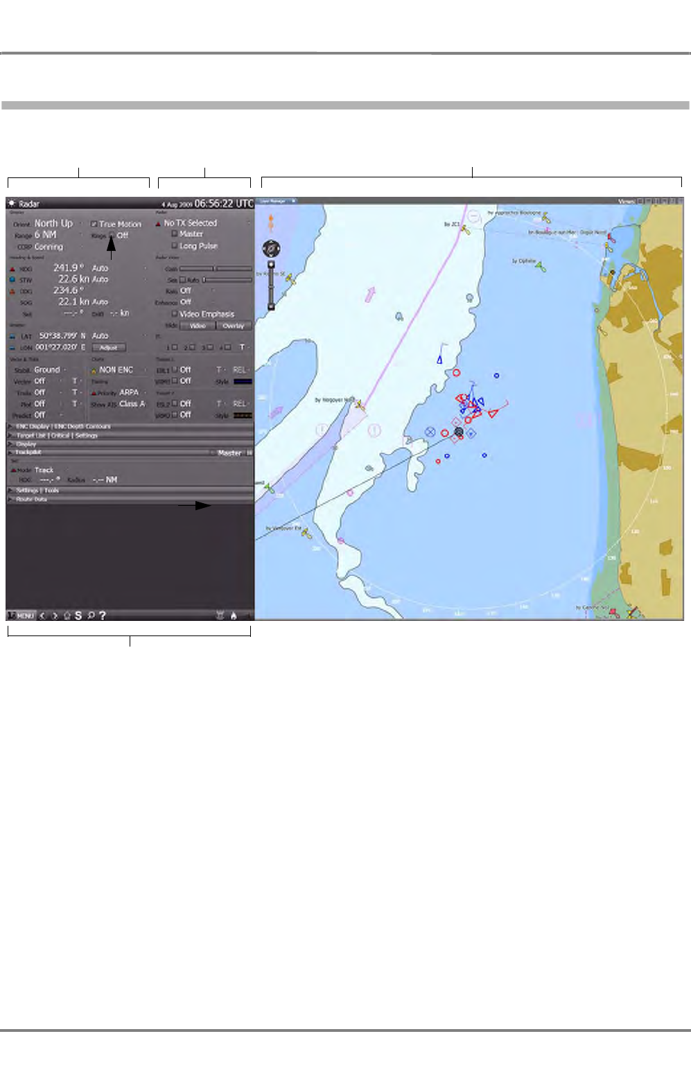
ED 3100 G 110 / 02 (2011-10)
Operating Instructions
A-3 An Overview of the Screen
A RADAR.fm / 10.11.11 A-31
NACOS Platinum
3 An Overview of the Screen
Fig. A / 7 Overview of the RADAR screen
Application part RADAR part RADAR application area
Sidebar

NACOS Platinum
ED 3100 G 110 / 02 (2011-10)
Operating Instructions
A-3 An Overview of the Screen
A RADAR.fm / 10.11.11
A-32
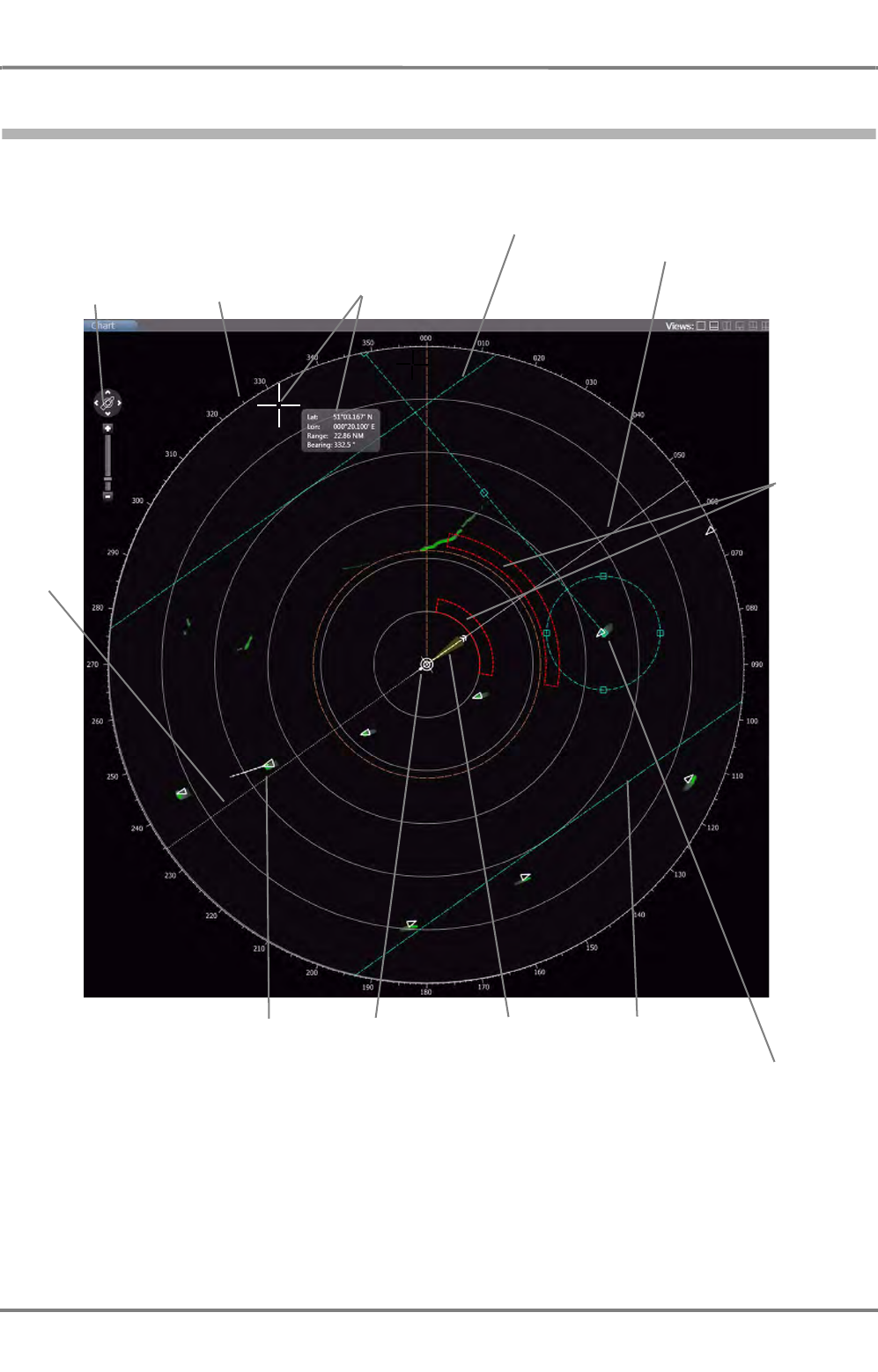
ED 3100 G 110 / 02 (2011-10)
Operating Instructions
A-4 RADAR Application Area
A RADAR.fm / 10.11.11 A-33
NACOS Platinum
4 RADAR Application Area
Fig. A / 8 PPI with superimposed elements
For detailed information about the handling of the displayed elements see the following chapters.
Bearing scale
Parallel index line
EBL2/VRM2, decentered
EBL1/VRM1,
centered
RADAR video,
with emphasis
and superim-
posed AIS target
symbol
Heading
line
Pointer with
position infor-
mation
Stern
line
Vector,
bottom track
and look-ahead
sector
Parallel index lines
Pan and
Zoom Control
Guard- /
Aquisition
Zone
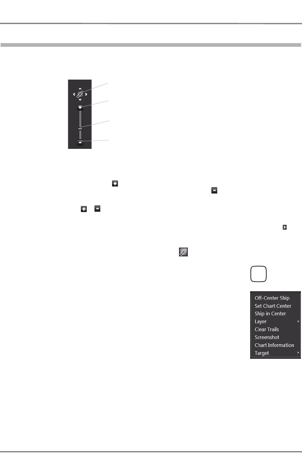
NACOS Platinum
ED 3100 G 110 / 02 (2011-10)
Operating Instructions
A-4 RADAR Application Area
A RADAR.fm / 10.11.11
A-34
4.1 The Zoom and Pan Control
The zoom control in NACOS Platinum consists of a slider to adjust the range setting for the radar or the
zoom factor for the ECDIS chart display. The compass control consists of pan buttons, which you can
use to move the image section currently displayed.
Fig. A / 9 Zoom and Pan Control
To zoom in incrementally, click on , you will then see more details on the respective display. However,
the overall area displayed is smaller. To zoom out again, click on the . You will then see less details
but you will have a better general overview of, e.g. an electronic chart displayed.
Using the slider or the / controls switches the range for radar or the zoom factor for ECDIS in the
steps described later on.
To pan the display, use the panning arrows of the compass control. For example, if you click on then
the display moves to the right in increments to view a different image section of a chart or whatever is
displayed. The effect is like travelling with the eye over a large map.
To center the display, e.g. after panning, just click on the icon once.
☞ It is also possible to off-center and re-center the ship by means of the
context menu or by means of the button on the radar keyboard.
Compass control
with 4 pan arrows
Slider to adjust zoom
factor
Zoom in
Zoom out
CENT
or
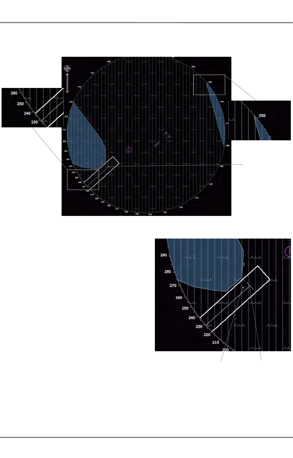
ED 3100 G 110 / 02 (2011-10)
Operating Instructions
A-4 RADAR Application Area
A RADAR.fm / 10.11.11 A-35
NACOS Platinum
Due to the fact that the bearing scale relates to the position of the CCRP in the PPI, the division of the
bearing scale is altered in a way that the scale still fits to the de-centered position of the CCRP.
In the case that a very large ship uses a very
small scale for the display (e.g. 250m) it might
happen that parts of the ship´s outline are situ-
ated outside of the PPI. But neither the CCRP
nor the indication of the position of the selected
radar antenna itself can ever leave the PPI,
regardless of the settings for CCRP.
Before either the CCRP or the indication of the
position of the selected radar antenna will leave
the PPI, they will be shifted back to the oppo-
site point where they are supposed to leave
according to the ship´s movement at the time
when the CCRP/the antenna indication have
reached 70% of the radius of the PPI, meas-
ured from the centre.
Origin of the
bearing scale
CCRP
Indication of the position of
the selected radar antenna
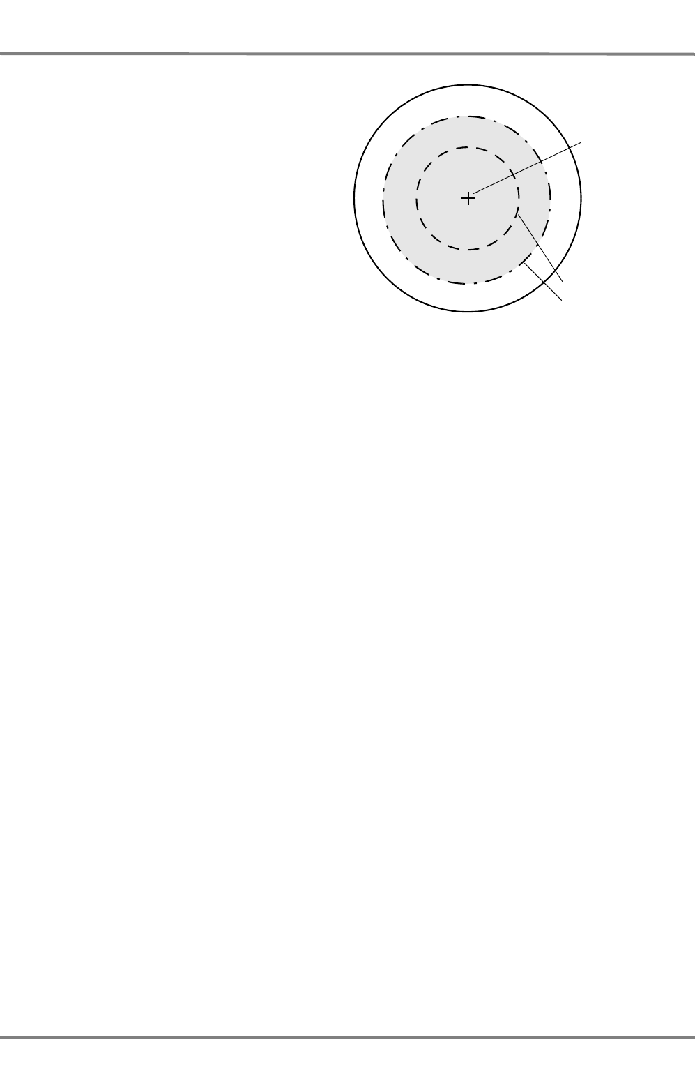
NACOS Platinum
ED 3100 G 110 / 02 (2011-10)
Operating Instructions
A-4 RADAR Application Area
A RADAR.fm / 10.11.11
A-36
Centre of the PPI
50% of the radius
70% of the radius
Light grey area:
The area where
the off-centered
CCRP or position
indication of the
radar antenna
may be located.
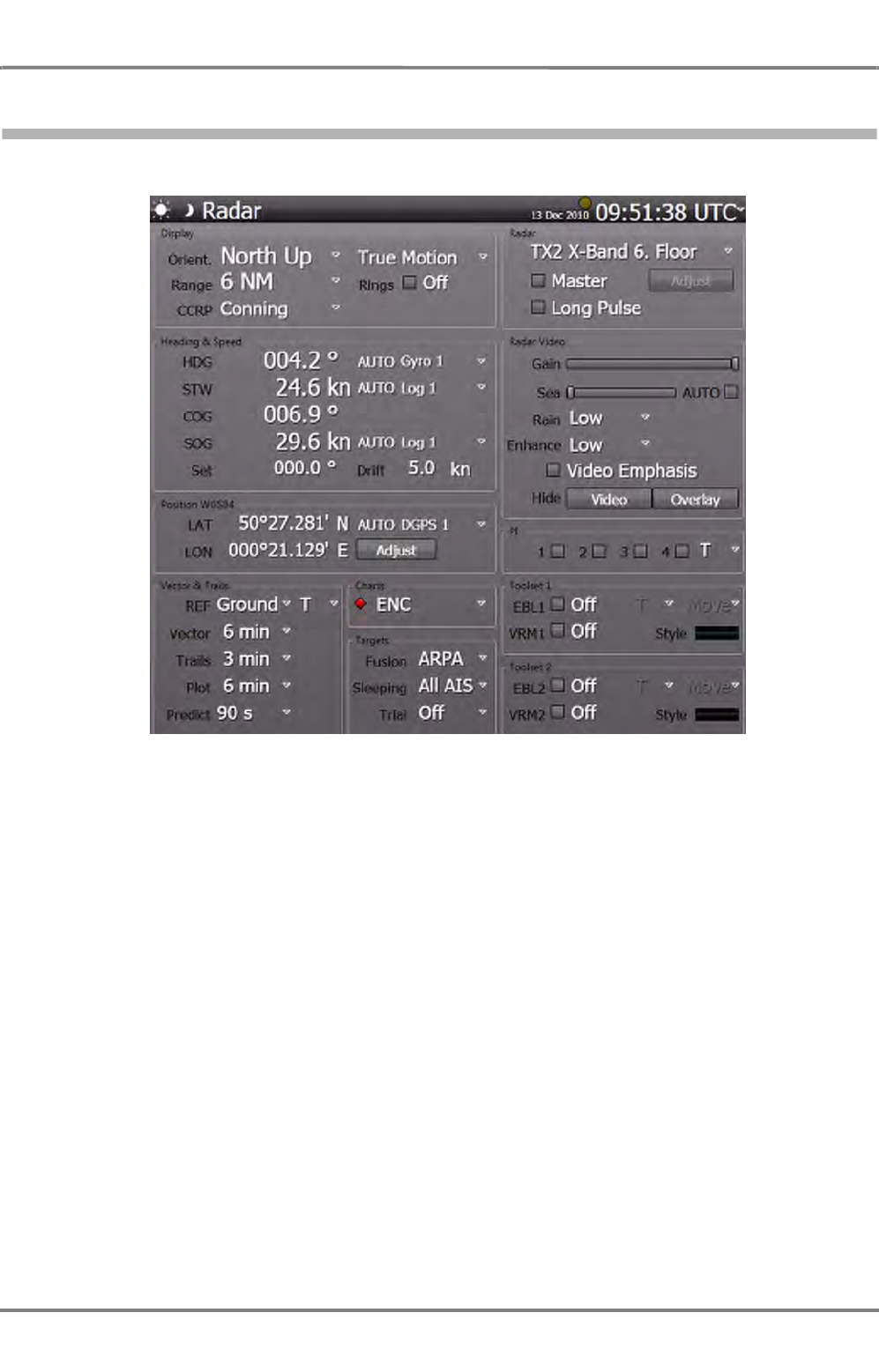
ED 3100 G 110 / 02 (2011-10)
Operating Instructions
A-5 RADAR Sidebar - Permanent Area
A RADAR.fm / 10.11.11 A-37
NACOS Platinum
5 RADAR Sidebar - Permanent Area
Fig. A / 10 An Overview of the Permanent Area of the RADAR
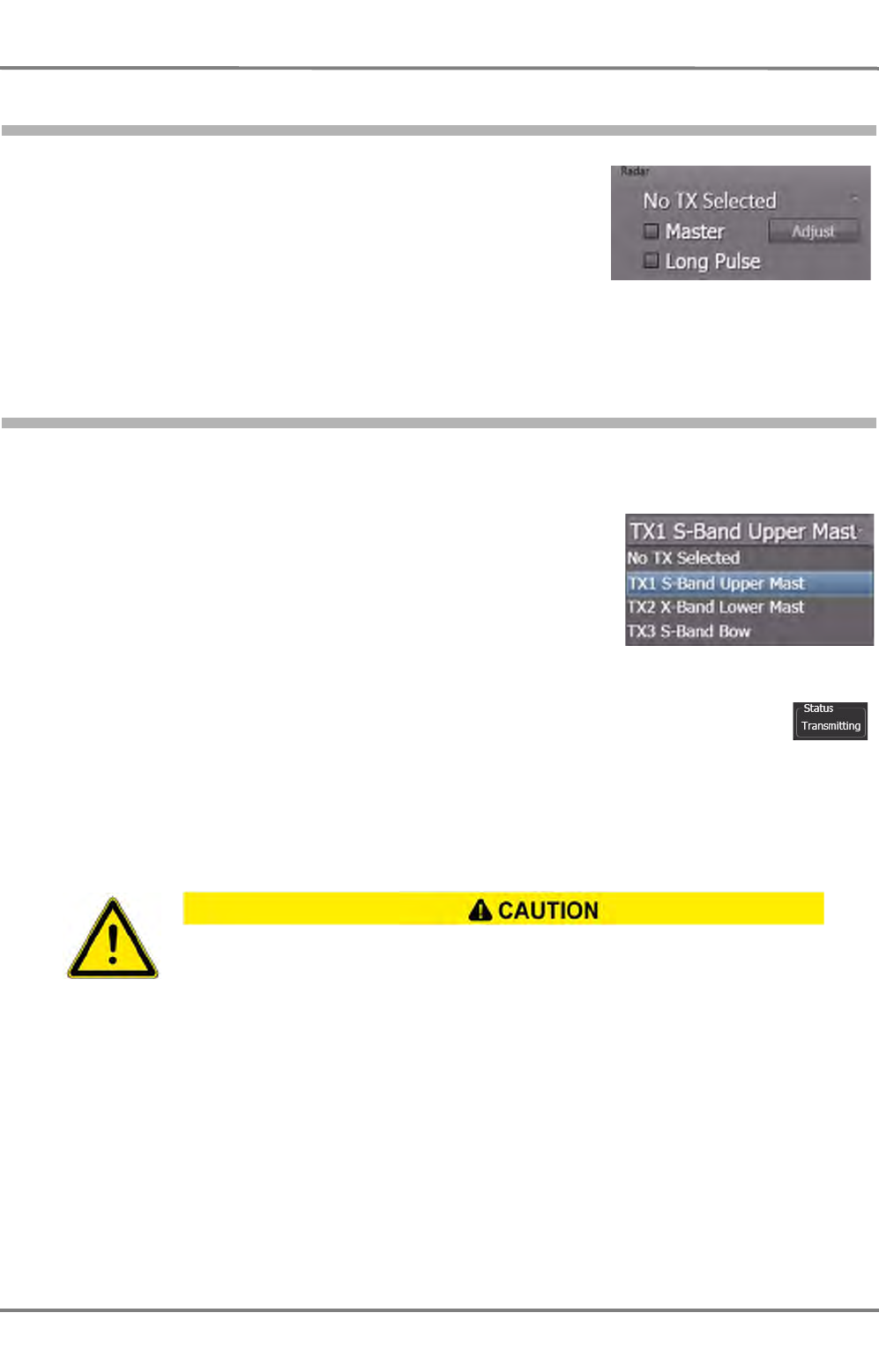
NACOS Platinum
ED 3100 G 110 / 02 (2011-10)
Operating Instructions
A-5 RADAR Sidebar - Permanent Area
A RADAR.fm / 10.11.11
A-38
5.1 RADAR Transceiver Settings
This group offers the selection of the desired radar transceiver and
basic settings for the radar. The transceiver can be adjusted by
means of clicking on the Adjust button.
The Adjust button is only sensitive and operable when one of the available transceivers is selected and
connected to the MFD and the MFD is selected as master.
5.1.1 Transceiver Selection
From the dropdown-list select the transceiver whose radar video is to be displayed at the MFD. The
chosen transceiver and antenna motor are activated, if not yet done by another MFD.
If No TX Selected is chosen, the appropriate transceiver is turned
off and the respective antenna stops rotation, if it is not selected by
another MFD.
In order to have the current status of one of the transceivers in the list displayed, move
the pointer to the depiction of the transceiver and let it stay for about one second, a small
window pops open and shows the information.
A transceiver with the status Not Connected cannot be activated or controlled in any
way.
☞ It is not advisable to select RADAR as the CCRP in the Display group of the Permanent Area, if
No TX Selected has been chosen. In this case, all instruments would become invalid as the RADAR
CCRP is not defined.
At the instant of switch-on of the radar function, the antenna begins to rotate and the
emission of high frequency radiation is started. In the case of multiple installations, it can
also happen that, instead of the expected antenna, a different one begins to rotate. There-
fore, it must be ensured beforehand that the antennas can rotate freely and that there is
nobody present close to the antenna turning circles.
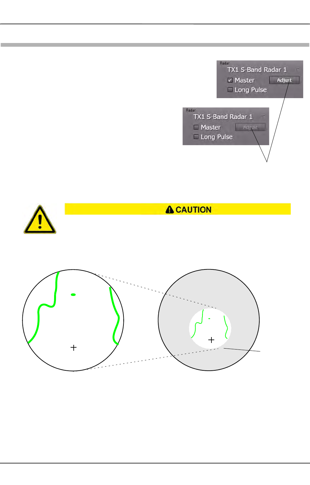
ED 3100 G 110 / 02 (2011-10)
Operating Instructions
A-5 RADAR Sidebar - Permanent Area
A RADAR.fm / 10.11.11 A-39
NACOS Platinum
5.1.2 Master / Slave Selection
If Master is selected, the appropriate MFD becomes the
master operating unit for the transceiver. The former
master MFD for the selected transceiver is no longer
master and on its screen the checkmark will disappear.
Any MFD of the system configured as a radar indicator on
service level can be switched to act as the master. On
the master indicator, the radar transmitter and the
receiver are operated. A slave-indicator cannot operate
the transmitter, but it can control the video adjustments
on the MFD.
If you try to become the master of a transceiver with the
status Not Connected, the checkmark of the Master
selector will disappear and the Adjust button will
become insensitive again within 1-2 seconds.
Technical background: The radar picture generated by the transceiver always has twice the diameter of
the selected range of the master transceiver, in order to ensure a proper function of the off-center mode.
Picture distortions may occur on the slave MFD if the radar range selected by the master
MFD is more than one step smaller than the radar range of the slave and the slave indi-
cator is de-centered.
Adjust control changes state when master
changes.
Master, 3 NM Slave, 12 NM
Due to the fact
that the range
of the master
is more than
one step
smaller than
the range of
the slave,
details outside
the 6 NM
(=2 x 3 NM)
range are not
visible!
Scetch is not to scale!
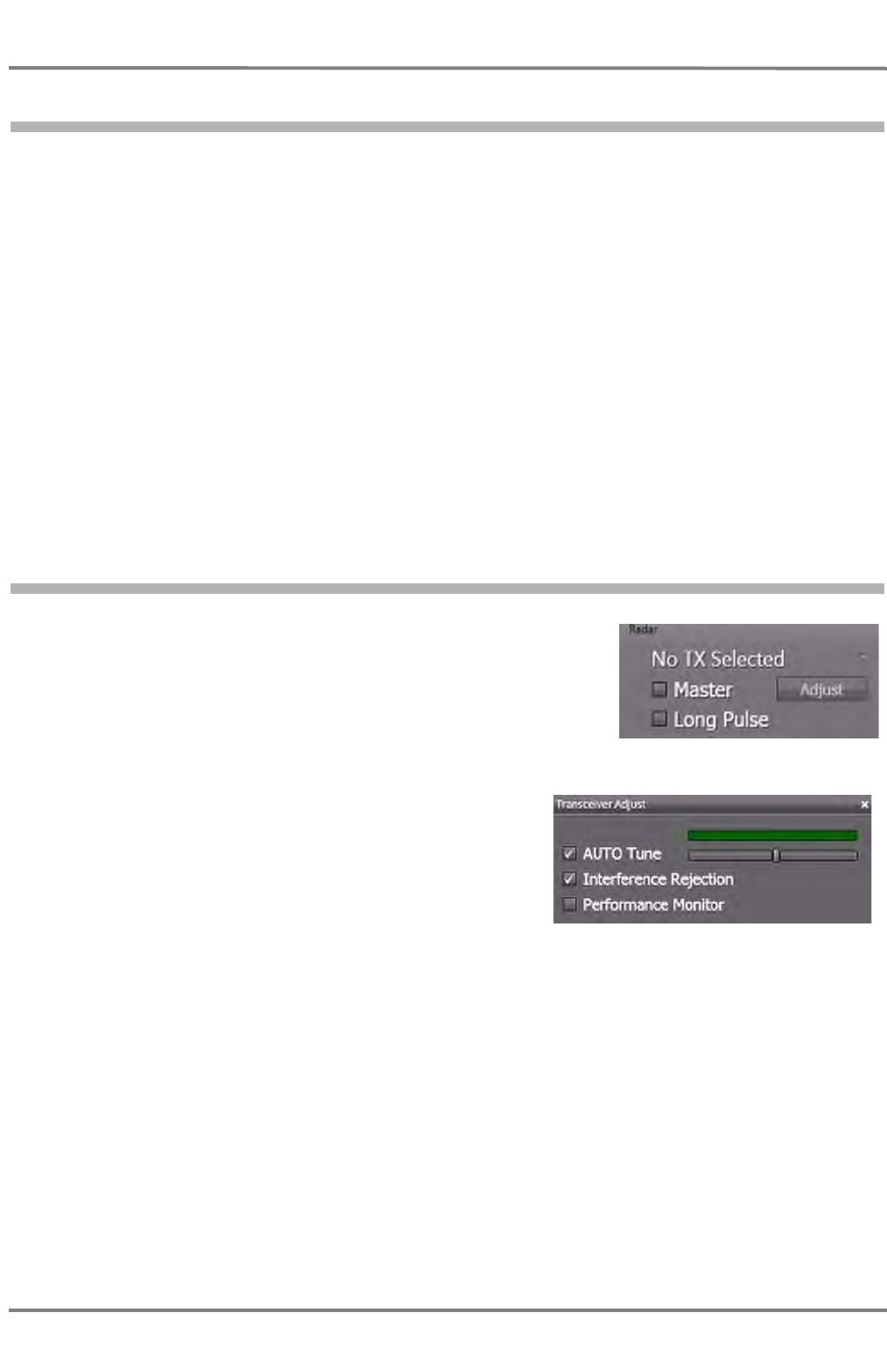
NACOS Platinum
ED 3100 G 110 / 02 (2011-10)
Operating Instructions
A-5 RADAR Sidebar - Permanent Area
A RADAR.fm / 10.11.11
A-40
5.1.3 Pulse Length
Long Pulse is available for any range of the radar. The internal pulse length changes with respect to
the selected range automatically. For detailed information on the pulse lengths for any range, please
refer to page A-23.
The default setting for the pulse length should be short pulse, which means no checkmark on
Long Pulse.
The short pulse delivers a better resolution, targets which are very close together will be displayed as
separated echoes.
A longer pulse has a higher energy, but not a higher amplitude. Thus, it delivers stronger echoes and
possibly a better target visibility at longer ranges. But it may be possible that two targets which are very
close together would be displayed as one echo.
In general, it is advisable not to use the long pulse in rainy conditions.
It is allowed to switch between the two pulse lengths at any time.
If target enhancement or any other filtering methods are active, the stronger echoes are processed by
the filters and are able to improve a weak radar picture.
5.1.4 Adjusting the Transceiver
The selected transceiver´s tuning and Interference Rejection can
only be adjusted by the MFD which is selected as Master for it.
If Master is not selected, the Adjust control will be insensitive.
Tuning
The tuning (adjustment of the transceiver frequency) can
be influenced manually or by means of the automatic
control.
☞ An optimum tuning is not only important for a clear
visual display of the targets on the video but is also a
necessary prerequisite for the ARPA functions.
Automatic tuning
The default setting is Auto Tune, the transceiver frequency is controlled automatically.
The slider is moved automatically by the system into the position of the optimal value.
If two X-Band or two S-Band systems are being operated simultaneously, disturbance of automatic tuning
might occur (if it is being used). In such cases, manual tuning is appropriate.
Manual tuning
Clear the Auto Tune checkbox and use the slider to perform manual tuning. The green indicator bar
above the slider corresponds to the amplitude with which the input signal is available for signal
processing. Observe more than one antenna rotation to find the maximum.
Interference Rejection
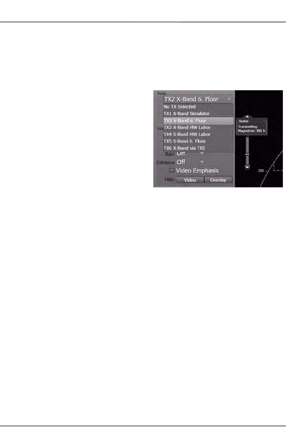
ED 3100 G 110 / 02 (2011-10)
Operating Instructions
A-5 RADAR Sidebar - Permanent Area
A RADAR.fm / 10.11.11 A-41
NACOS Platinum
Interference caused by other radars (see page A-19) can usually be eliminated by switch-on of the inter-
ference rejection function. The default setting for Interference Rejection is On, but it can temporarily
switched of by the operator.
Peformance Monitor
See chapter H - 1 on page H-3 for details about the operation of the Performance Monitor.
Magnetron Hours
The transmitting valve or magnetron is the only
device which has in comparison to other elec-
tronic devices in the radar system a limited life-
time. Typical running time hours are given in
the Maintenance section chapter 3.2.
In order to check the actual operational hours of
a specific magnetron just place the cursor on
the transceiver in question in the selection list
and a small status window is opened with the
magnetron hours.
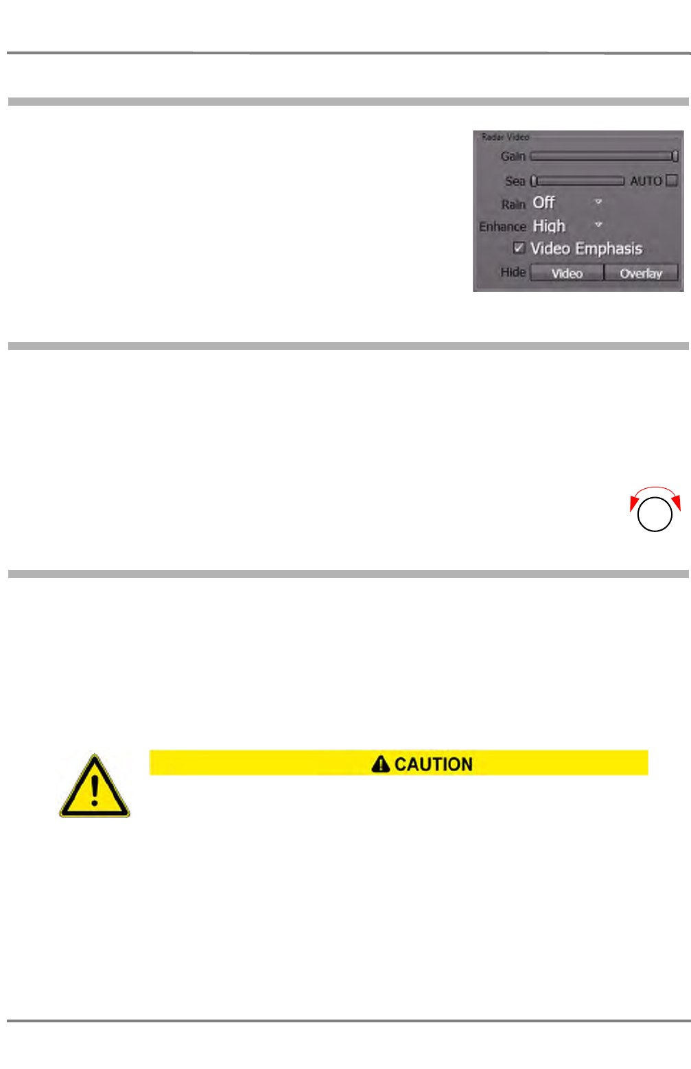
NACOS Platinum
ED 3100 G 110 / 02 (2011-10)
Operating Instructions
A-5 RADAR Sidebar - Permanent Area
A RADAR.fm / 10.11.11
A-42
5.2 RADAR Video Settings
This group shows options which influence the display of the radar
video on the MFD. These settings are influencing only the radar
video on the operated MFD, but not on other MFDs which are
connected to the same transceiver as slave or master.
5.2.1 Gain
Gain setting influences the amplitudes of all echoes and works like an amplifier that makes it possible
to enhance all echoes and noise in the same way in order to get a better picture. But, also the noise will
be amplified and can disturb the clear display of targets.
☞ For optimum setting, adjust the Gain slider in a way that slight noise is visible on the PPI. Then
reduce the value a little until the noise has just disappeared, but not more.
The gain can also be set by means of the Gain turning knob on the radar keyboard.
5.2.2 Sea
Sea can be set to manual or automatic mode. In manual mode, its setting influences the amplitudes of
the radar echoes in such a way that it attenuates echoes close to the antenna very much and that it
attenuates echoes which are more distant to it only very little. Due to the fact that the distance of a
target is represented by the time its echo needs to return to the antenna, this is called „sensitivity-time-
control“ (STC). Nevertheless, echoes which are as strong as the unwanted reflections of the sea surface
may be fully suppressed and not visible, or they may appear and disappear, depending on how strong
the surrounding unwanted reflections are.
In automatic mode, a fixed, approved value for the Sea filter is set. Advantages or limitations to the
effect are the same as in manual mode.
☞ The automatic anticlutter sea function has the advantage that the clutter values taken into account
in the upwind direction are different from those taken into account in the downwind direction.To
check the display of very small target-echoes, it is necessary to switch over to manual operation.
In the case of anticlutter sea values that are too large, weak targets can be lost, especially
at close range. If the sea is very rough, it can be expected that radar targets which only
produce weak reflections will remain undetected, even if the setting is correct.
Gain
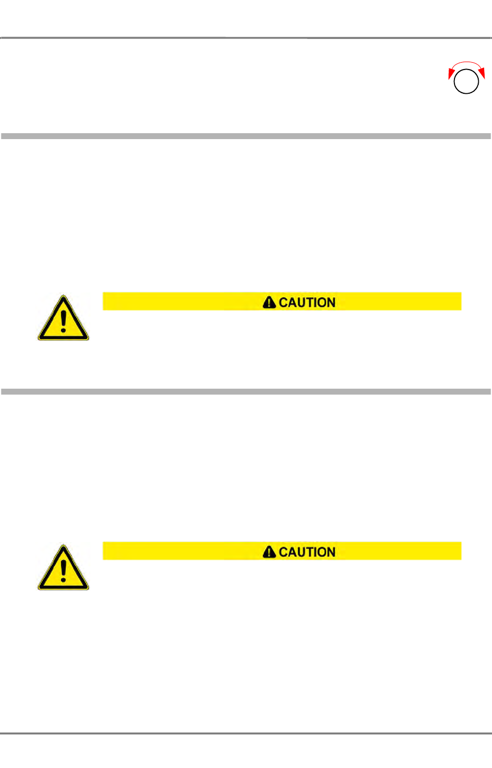
ED 3100 G 110 / 02 (2011-10)
Operating Instructions
A-5 RADAR Sidebar - Permanent Area
A RADAR.fm / 10.11.11 A-43
NACOS Platinum
The sea clutter suppression can also be set by means of the turning knob on the radar
keyboard.
5.2.3 Rain
The suppression of rain clutter can be set to Off or to three values: Low, Medium or High.
If the value is set to Low or Medium, the filter works with pre-set coefficients just like in manual mode,
if the value is set to High, the suppression is operated with correlative coefficients like in automatic
mode.
The anticlutter rain function has the advantage that it takes place individually for regions with widely
differing precipitation.
To check the display of very small target-echoes in a rain area, it is necessary to switch over to manual
operation.
5.2.4 Enhance
The target enhancement function is a scan-to-scan technology that helps differentiate between radar
targets and noise. It can be set to Off or to three automatic values: Low, Medium or High.
Refer to chapter 1.5 for the correct gain setting in combination with the activation of the Enhance func-
tion.
Target enhancement is used to display even very small or weak targets. For example, if a target echo is
this small that it only lights up one pixel of the screen, it could be overseen or regarded as noise or
clutter. Target enhancement makes it a little bigger, so that it is better to discover among the more
dynamic clutter or noise. With this enhanced target, the correlation filter can work much more precisely.
In the case of heavy rain, snow and hail, it can be expected that, even if the setting is
correct, radar targets which only produce weak reflections - especially targets situated
behind a strong rain front - will remain undetected. Such targets can appear suddenly
when leaving the rainy area.
When the Enhance function is running, the scan-to-scan correlation might have
the result that small, fast-moving targets like high speed crafts or Racon codes
are displayed with reduced intensity or might be fully suppressed.
Sea
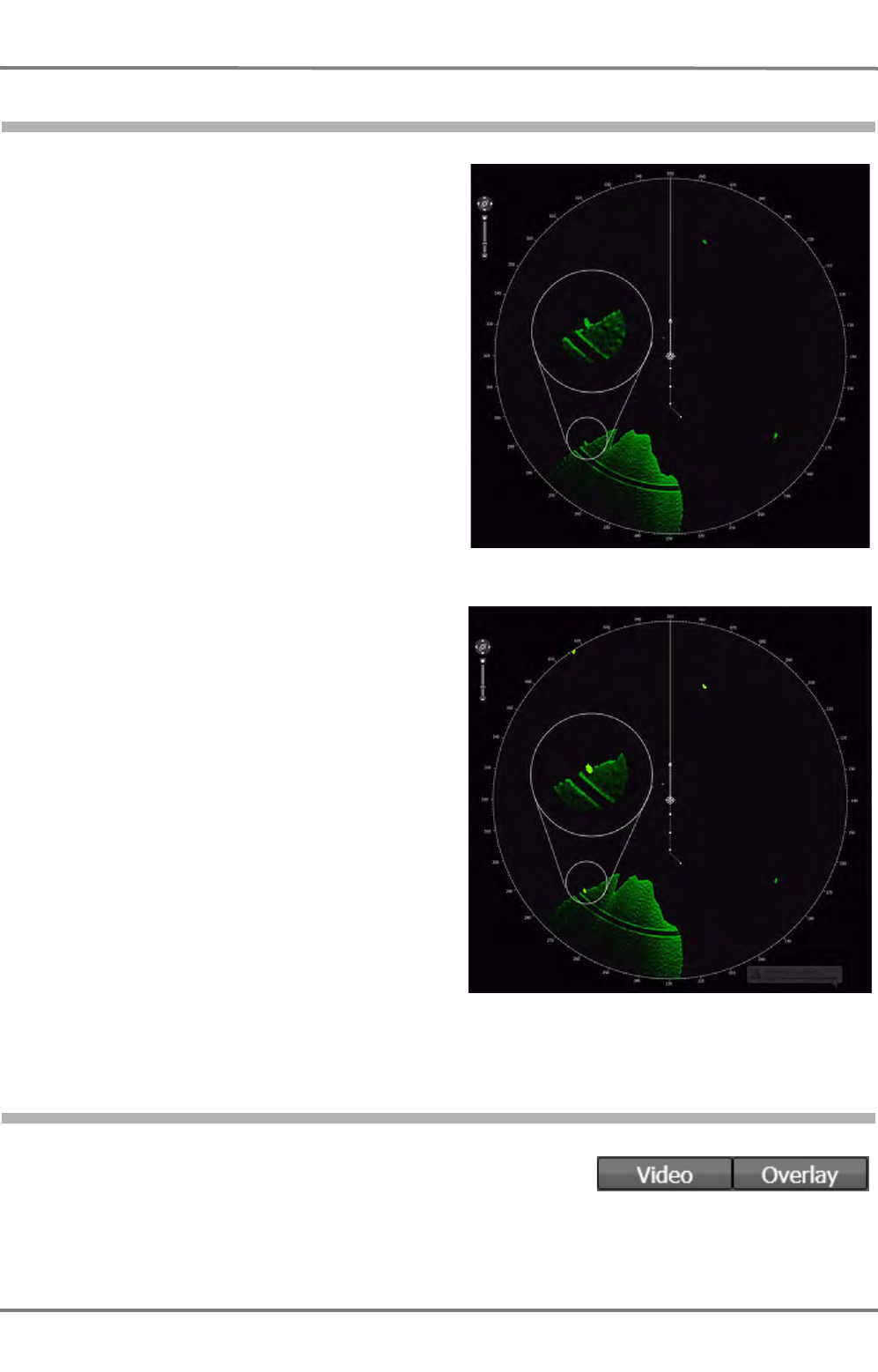
NACOS Platinum
ED 3100 G 110 / 02 (2011-10)
Operating Instructions
A-5 RADAR Sidebar - Permanent Area
A RADAR.fm / 10.11.11
A-44
5.2.5 Video Emphasis
Strong video signals can be accentuated optically
by switching on the Video Emphasis function.
Video Emphasis can be used to increase the
detection of targets of the radar. Very strong
echoes will be shown in light green colour. It can
help to decide whether an echo is one or two
combined objects or whether a strong object is
covered by noise, for example the echo of a cloud.
The display of targets on the PPI will be improved,
targets will not get lost if VE is switched off. Also
structures in land areas or in rainclouds or
seaclutter can be made more visible by the VE
function, for instance a light house on a land area
or buoys with only a short distance to the land,
whose echoes would normally melt into the ones of
the land.
The examples show a radar echo that is covered by
the noise of a raincloud.
5.2.6 Hide Video / Overlay
The radar video itself or the superimposed synthetics overlay can
be suppressed temporarily by holding down the appropriate push-
buttons. As soon as the pushbuttons are released, the video or
the synthetic overlay are displayed again.
RADAR picture without video emphasis
RADAR picture with video emphasis

ED 3100 G 110 / 02 (2011-10)
Operating Instructions
A-5 RADAR Sidebar - Permanent Area
A RADAR.fm / 10.11.11 A-45
NACOS Platinum
Suppression of the radar video or the synthetic overlay is also possible by means of the
radar keyboard. As long as the buttons are pressed down, the appropriate objects on
the PPI are suppressed.
Video Overlay
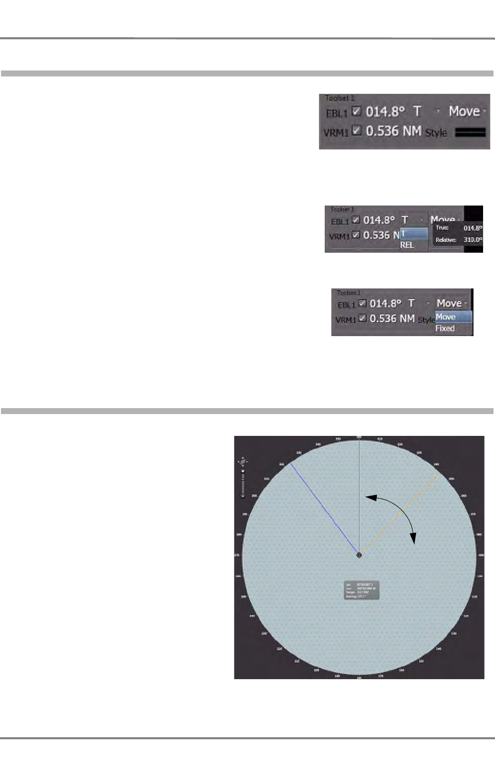
NACOS Platinum
ED 3100 G 110 / 02 (2011-10)
Operating Instructions
A-5 RADAR Sidebar - Permanent Area
A RADAR.fm / 10.11.11
A-46
5.3 Toolset1 and 2
Each toolset offers the use of one variable range marker (VRM)
and one electronic bearing line (EBL).
With the aid of the EBL and VRM bearings and distances
between an object and the own ship or bearings and distances
between two objects can be determined.
☞ When measuring bearing and distance between the own
ship and an object, the current setting of the CCRP must
be considered: The CCRP set to RADAR gives measure-
ments relative to the selected radar antenna, and CCRP
set to Conning gives values relative to the conning posi-
tion on the bridge, as long as EBL and VRM are operated
in centered mode. See chapter 2.1 on page III-16.
Using the dropdown-list beneath T, it can be chosen wether
the bearing is to be displayed as true bearing (T) or relative
bearing (REL). When the pointer is moved upon the dropdown
list, a windows appears showing the true and relative bearing
of the recent VRM.
Additionally, Move can be chosen if the origin of the bearing
line is to move together with the own ship, Fixed can be
selected if the origin is to remain at an absolute position on the
screen.
5.3.1 EBL
With the EBL, the bearing of an object with
respect to own ship or the bearing
between two objects can be determined.
After switch-on by means of a click in the
Toolset group, the EBL are superimposed
in the PPI. EBL appear with the same data
as they have been displayed last time.
In order to alter the bearing of the EBL,
click on it in the PPI. The EBL is now
displayed with a small "handle" in its
middle. Click and hold the handle and pull
the line to the desired bearing.
In order to change the origin of the
bearing line, click and pull its origin to the
desired position.
Switch the EBL off and on again in order
to re-center it on the own ship.
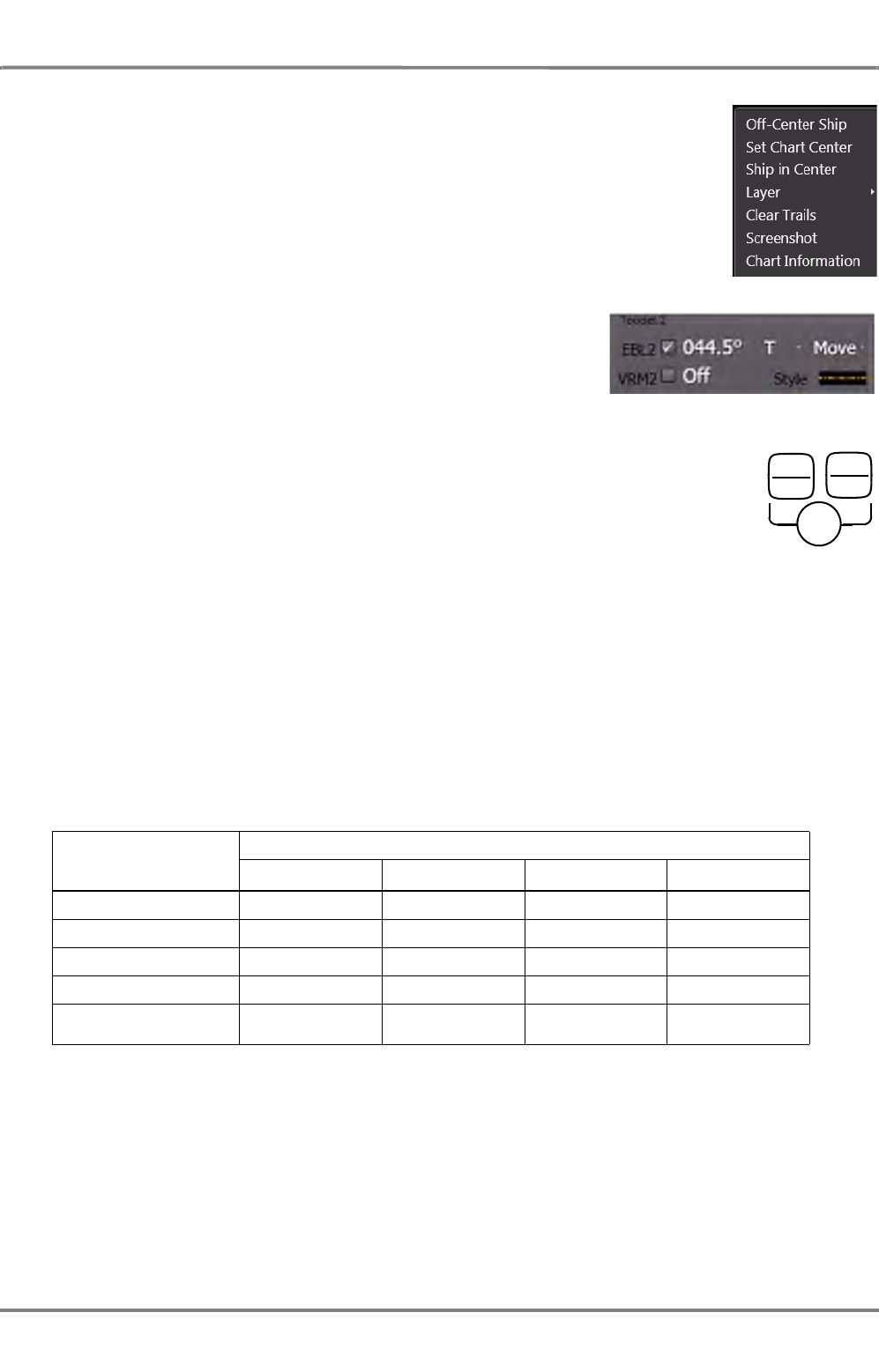
ED 3100 G 110 / 02 (2011-10)
Operating Instructions
A-5 RADAR Sidebar - Permanent Area
A RADAR.fm / 10.11.11 A-47
NACOS Platinum
Re-centering of the EBL (and VRM if joined) can also be done by the context menu
in the application area. Right-click in the PPI and choose Center EBLx.
The current bearing is displayed in the Toolset group.
To switch off display of the EBL, clear the checkbox in the Toolset
group.
The EBL can also be set by means of the radar keyboard.
To switch on the EBL, press the button for a short time. Adjust the bearing by
means of the rotary knob. To switch off the EBL, press the button for about 2
seconds.
Latitude-Dependent Errors in the Display of the EBL
With the type of projection used for the longitude/latitude grid in the radar, the parallels of latitude
become more strongly curved with increasing latitude, while the meridians converge increasingly with
increasing distance from the equator (i.e. the direction of a meridian at the edge of the PPI is not 0° -
180° but might be 358° - 182°); in other words, their directions no longer correspond to the degree
scale at the edge of the PPI.
In contrast to this, the EBL is always displayed as a straight line; its bearing displayed as an EBL value
has a deviation with its maximum at the most distant point from own ship.
The following table shows the maximum bearing deviation for various latitudes and range settings.
Table A / 9 Latitude-Dependent Errors of the EBL
Distance of EBL from
Own Ship Geographical Latitude
20 ° 40 ° 60 ° 80 °
10 NM < 0.1 ° 0.1 ° 0.3 ° 0.9 °
20 NM 0.1 ° 0.3 ° 0.6 ° 1.9 °
40 NM 0.2 ° 0.5 ° 1.2 ° 3.8 °
60 NM 0.4 ° 0.8 ° 1.7 ° 5.7 °
80 NM 0.5 ° 1.1 ° 2.3 ° 7.5 °
EBL1
OFF
EBL2
OFF
Bearing
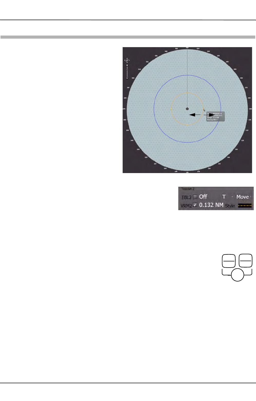
NACOS Platinum
ED 3100 G 110 / 02 (2011-10)
Operating Instructions
A-5 RADAR Sidebar - Permanent Area
A RADAR.fm / 10.11.11
A-48
5.3.2 VRM
With the variable range markers, the
distance of an object from own ship or (in
conjunction with the EBL) the distance
between two objects can be measured.
After switch-on by means of a click in the
Toolset group, the VRM are superim-
posed in the PPI. VRM appear with the
same data as they have been displayed
last time, if the VRM range is below the
display range. Otherwise it is switched on
at 50% of the displayed range.
In order to alter the range of the VRM,
click on it in the PPI. The VRM is now
displayed with four small "handles". Click
and hold one of the handles and pull the
ring to the desired radius.
The current VRM radius is displayed in the
Toolset group.
To switch off display of the VRM, clear the checkbox in the Toolset
group.
☞ If the display range is reduced when the VRM is in the switched-on state, the VRM might be situated
outside the visible range. Switch the VRM off and then on again, to return it to the visible range.
The VRM can also be set by means of the radar keyboard.
To switch on the VRM, press the button for a short time. Adjust the range by means of
the rotary knob. To switch off the VRM, press the button for about 2 seconds.
VRM1
OFF
VRM2
OFF
Distance
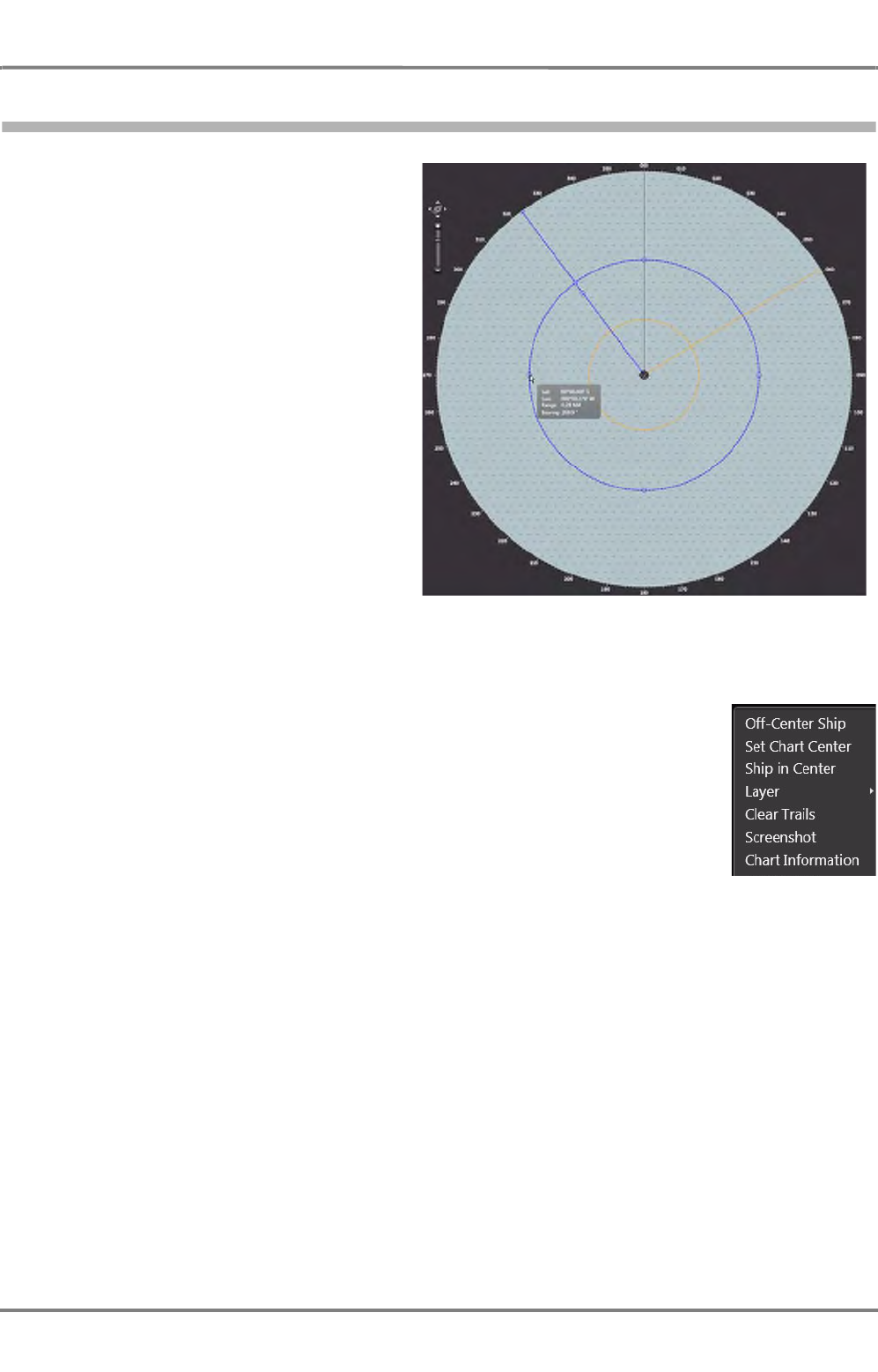
ED 3100 G 110 / 02 (2011-10)
Operating Instructions
A-5 RADAR Sidebar - Permanent Area
A RADAR.fm / 10.11.11 A-49
NACOS Platinum
5.3.3 Operating VRM and EBL jointly
Two sets of EBL and VRM can be operated
jointly without influencing each other.
They are displayed with differing colours.
EBL1 and VRM1 are combined in one
toolset, as well as EBL2 and VRM2.
The activation of EBL1 also activates VRM1
if both are in the switched on state. To
activate the joined setting click on the
intersection of EBL and VRM. Both objects
get the small "handles" and can be oper-
ated.
Additionally, the intersection point
between VRM and EBL is marked and can
be used to alter bearing and range simul-
taneously.
The origin of the EBL and the VRM can be
changed simultaneously by clicking and
pulling their origin.
To re-center the combined EBL and VRM,
switch the EBL off and on again. Switching
off the EBL only recenters the VRM.
Re-centering of the EBL (and VRM if joined) can also be done by the context menu
in the application area. Right-click in the PPI and choose Center EBLx.
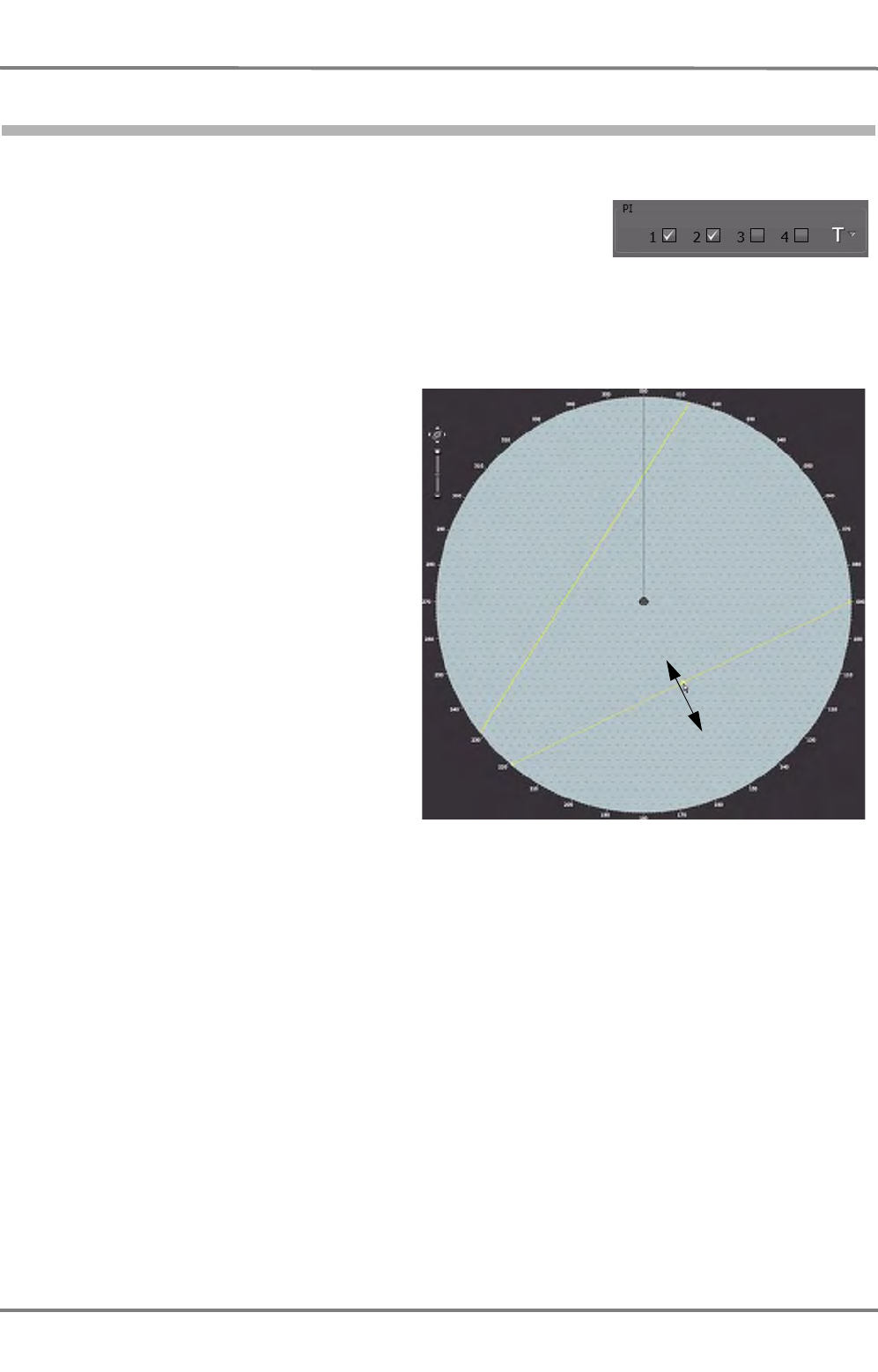
NACOS Platinum
ED 3100 G 110 / 02 (2011-10)
Operating Instructions
A-5 RADAR Sidebar - Permanent Area
A RADAR.fm / 10.11.11
A-50
5.4 Parallel Index Lines (PI)
There are 4 independent Parallel Index Lines available.
Depending on the setting in the PI group, the bearing is displayed as
true (T) or relative (REL) bearing
☞ When parallel index lines are switched on, they appear in the form in which they were set last. If
the display range has been reduced in the meantime, they might be situated outside the visible
range. In order to make the lines visible again without changing the range, the context menu can
be used. See description on next page for details.
The four parallel index lines can be
adjusted individually. The picture shows
two of them.
After switch-on by means of a click in the
PI group, the lines are superimposed in
the PPI. They appear with the same data
as they have been displayed last time.
In order to alter the distance of a line, click
on it. The line is now displayed with a
small "handle". Click and hold the handle
and drag the line to the desired distance.
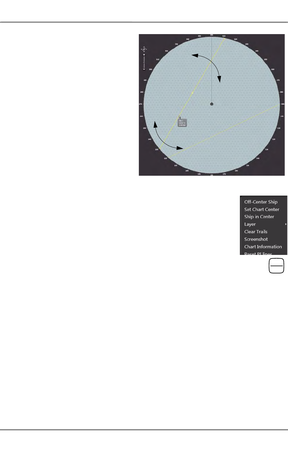
ED 3100 G 110 / 02 (2011-10)
Operating Instructions
A-5 RADAR Sidebar - Permanent Area
A RADAR.fm / 10.11.11 A-51
NACOS Platinum
In order to change the bearing of the line,
click on it. Then click and hold the line
anywhere but not on the small handle and
rotate it to the desired bearing.
The balloon-text shows the actual bearing
and distance data of the line.
To reset the PI lines to the default state, right-click in the PPI and choose Reset
PI lines in the context menu. The lines are set to 45° and 25% or 50% of the
display range to both sides of the PPI-center.
The PI can also be switched on or selected by means of the radar keyboard. Press
the key for a short time. The PI are switched on in numerical order, starting with the one that
had been used last. To switch off a specific PI, use the checkboxes 1...4 in the PI group or
select the specific PI with a short keypress on the PI-button and then switch off by pressing it
for about 2 seconds.
Depending on the system configuration, the Non-permanent Area of the radar may not show every object
described in this part. For example, if there is no Trackpilot in the system, the appropriate expander is
not shown. Anyway, every possible expander will be described here.
In order to save space, a number of expanders have been combined into groups contained in three index
cards: Alarms, Presentation, Tools and Settings:
PI
OFF

NACOS Platinum
ED 3100 G 110 / 02 (2011-10)
Operating Instructions
A-5 RADAR Sidebar - Permanent Area
A RADAR.fm / 10.11.11
A-52
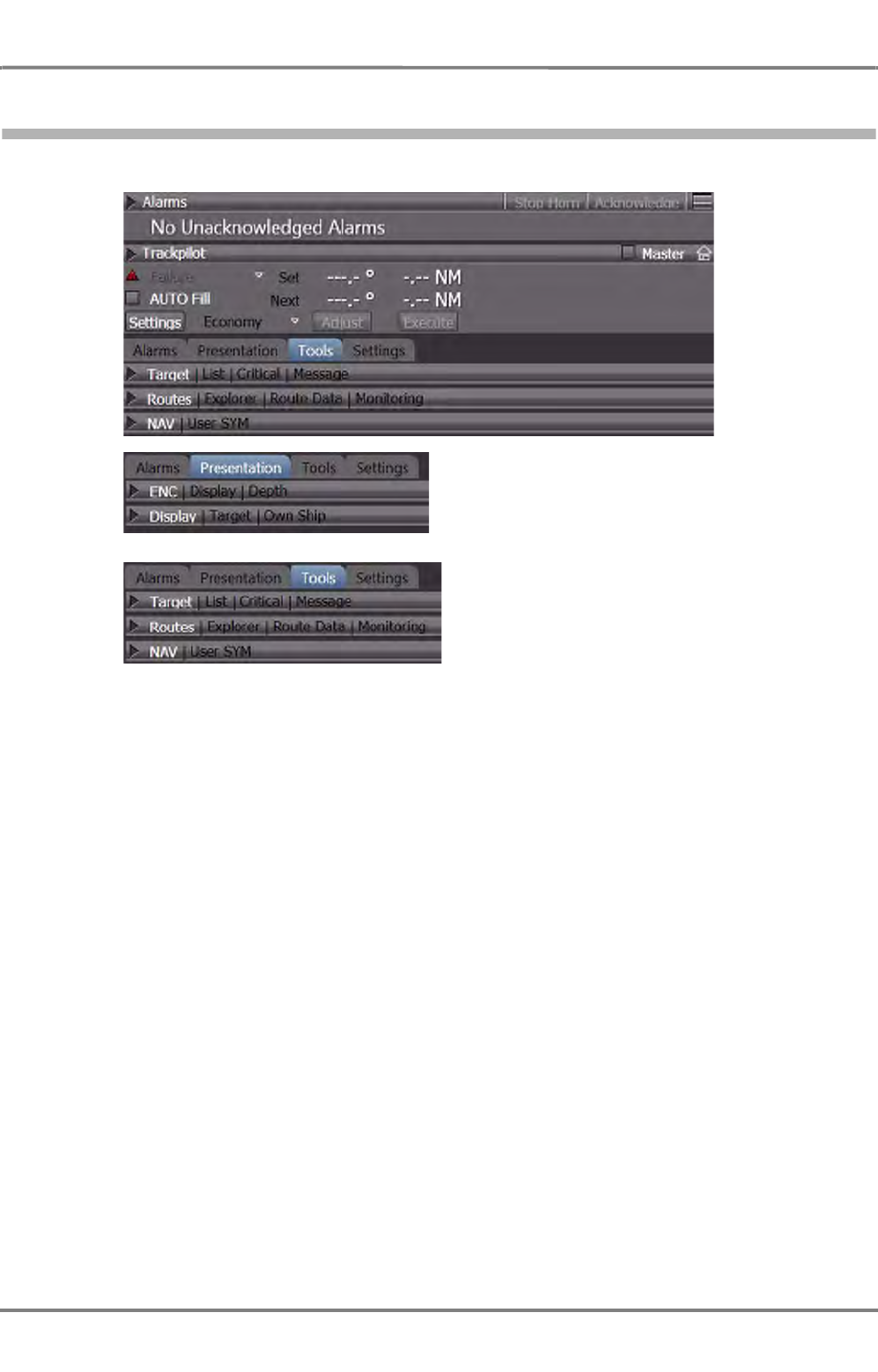
ED 3100 G 110 / 02 (2011-10)
Operating Instructions
A-6 RADAR Sidebar - Non-Permanent Area
A RADAR.fm / 10.11.11 A-53
NACOS Platinum
6 RADAR Sidebar - Non-Permanent Area
Fig. A / 11 RADAR Sidebar of the Non-Permanent Area
- The Alarm line shows the oldest not acknowledged alarm of highest priority and provides alarm
management
- The Alarm expander includes the alarm list and alarm settings for the ECDIS sub-system.
- The Trackpilot expander provides indications and control elements for the heading control and
automatic track keeping system
- The ENC expander provides settings for the visualisation of the electronic chart (ENC)
- The Display expander provides target, route and own ship settings and allows setting of user
symbols into electronic chart
- The Target expander provides the target list, the data of the most critical target and the AIS
mesage handling
- The Routes expander provides utilities for route planning, route management and route/display.
- The Settings expander contains different parameters for the setting of AIS and ARPA targets, the
automatic target acquisition and route display settings.

NACOS Platinum
ED 3100 G 110 / 02 (2011-10)
Operating Instructions
A-6 RADAR Sidebar - Non-Permanent Area
A RADAR.fm / 10.11.11
A-54

ED 3100 G 110 / 02 (2011-10)
Operating Instructions
A-7 Target Handling
A RADAR.fm / 10.11.11 A-55
NACOS Platinum
7 Target Handling
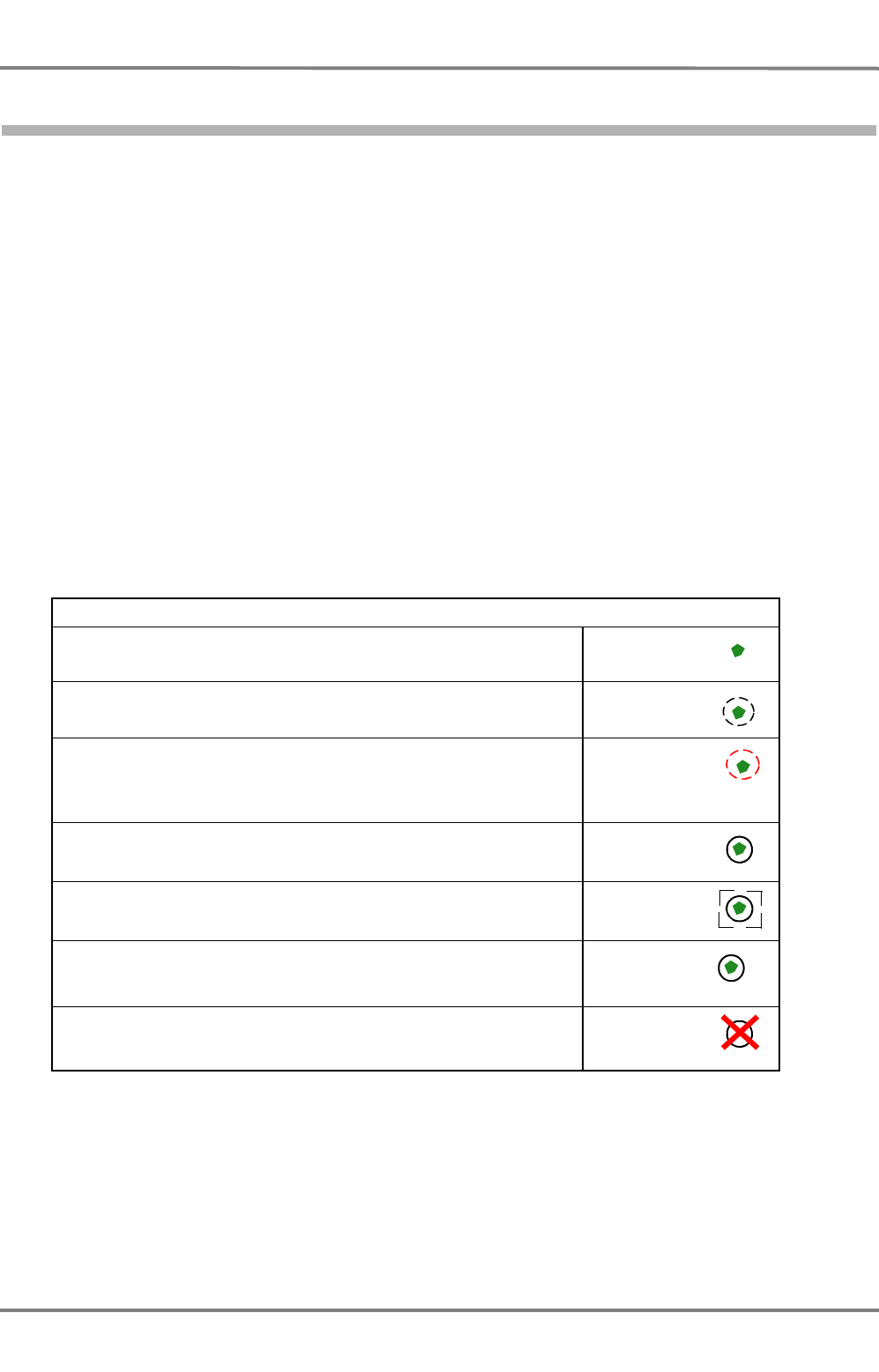
NACOS Platinum
ED 3100 G 110 / 02 (2011-10)
Operating Instructions
A-7 Target Handling
A RADAR.fm / 10.11.11
A-56
7.1 Overview
Two types of targets can be handled on the radar, ARPA targets and AIS targets. For the targets, the
AIS electronics unit and the ARPA electronics of the radar are two independent sensors whose displays
and operating procedures take place on one and the same MFD. The two sensors deliver data independ-
ently, the data of both sensors are used for the collision avoidance computation, which takes place in
the background of all actions. It can raise alarms, for instance if objects are on collision course.
☞ A radar echo that is supposed to be taken in account is called an acquired target.
☞ An AIS target that is supposed to be taken in account is called an activated target.
Targets can be acquired/activated manually using the GUI or automatically by the system. This chapter
first gives an overview of types of targets and their treatment in the system. If neccessary, cross refer-
ences to manual/automatic target acquisition are noted.
ARPA Targets
ARPA targets are acquired or tracked radar echoes received from the selected transceiver. They can be
tracked from a distance near 0 NM depending on antenna height and the target´s ship structure up to 24 NM
irrespective of the range scale in use. Before a radar echo can be used as ARPA target, its echo is evalu-
ated by the ARPA electronics during a number of antenna revolutions. ARPA targets can be of the
following kind:
Table A / 10 Symbols of ARPA Targets in RADAR
See the chapters below for further information.
ARPA targets
A radar echo on the PPI. It is displayed as a green bunch of pixels
A radar echo that has been acquired manually and that is under evalu-
ation now
A radar echo that has been acquired automatically by the examination
of the radar video in an acquisition/guard zone.
An acquired target that is tracked by the ARPA electronics. Its past posi-
tions and speed/direction vector can be shown
A tracked target, which is selected and whose data are marked in the
target list
ARPA targets may have an ID 1) displayed on the bottom right of the
symbol. The ID consist of a consecutive number generated by the
system preceded by the selected transceiver number.
1) ID is used as a shortcut for (target) identifier in these operating instructions.
Lost Target. If any of the abovementioned targets gets lost, a flashing
cross is superimposed above the target symbol.
flashing,
red
1 04
flashing,
red 1 04
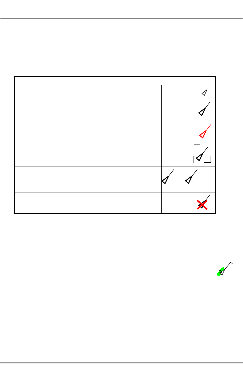
ED 3100 G 110 / 02 (2011-10)
Operating Instructions
A-7 Target Handling
A RADAR.fm / 10.11.11 A-57
NACOS Platinum
AIS Targets
AIS targets are all targets whose data are received by the AIS electronics unit connected to the system.
All AIS targets are visible per default after switch-on of the MFD.
☞ The display of groups of AIS targets (Class A, Class B , All) may be switched on and off by the
operator. Select All if you want to see all targets received from the AIS electronics unit.
AIS targets can be of the following kind:
Table A / 11 Symbols of AIS Targets
Target Fusion
Due to the fact that an AIS target within the radar range normally also produces a
radar echo, the symbols of tracked and activated targets are displayed close to each
other:
In this case, it is possible to decide whether the object is to be treated as an AIS
target or as an ARPA target. See chapter 3.5.1 on page III-59 for details. In terms of
an improved display readability and avoidance of cluttering the screen, the objects can
be fusioned if they meet some boundary conditions. That means, that they can be
displayed only as either AIS or as ARPA target depending on user selection. See
chapter 7.7 on page A-65 for details on Target Fusion.
☞ The number of ARPA and AIS targets being tracked should be kept as small as possible; the pres-
ence of too many targets causes confusion on the screen and distracts the operator's attention from
what is really important. Targets that are no longer relevant should be deleted (RADAR) or deacti-
vated (AIS).
AIS targets
A sleeping AIS target is a target that is displayed in the PPI. Its data
are evaluated and can be shown on demand.
A manually activated AIS target is displayed with detailed data such as
HDG, true scaled outline (if available in the received data set and the
PPI scale is large enough), ROT indicator, past positions and speed/
direction vector can be shown
An automatically activated target by the collision avoidance computation
or by a acquisition/guard zone
An activated AIS target, which is selected and whose data are marked
in the target list
AIS targets may have an ID displayed on the bottom right of the
symbol. The ID consists of the callsign or the ships name or the MMSI
depending on the settings in the target presentation menu.
Lost Target. If any of the above mentioned targets gets lost, a flashing
cross is superimposed above the target symbol.
For AIS targets the lost target alarm can be switched off in the Target
settings.
flashing,
red
BXGHE MS Hamburg
flashing,
red

NACOS Platinum
ED 3100 G 110 / 02 (2011-10)
Operating Instructions
A-7 Target Handling
A RADAR.fm / 10.11.11
A-58
☞ In the case of tracked targets entering a clutter area (rain or sea clutter), a "target swap" might
occur; parts of the rain front can suddenly be "tracked". A target swap can also occur if there are
targets situated close to each other or close to land. In the case of target swaps, no warning is
given.
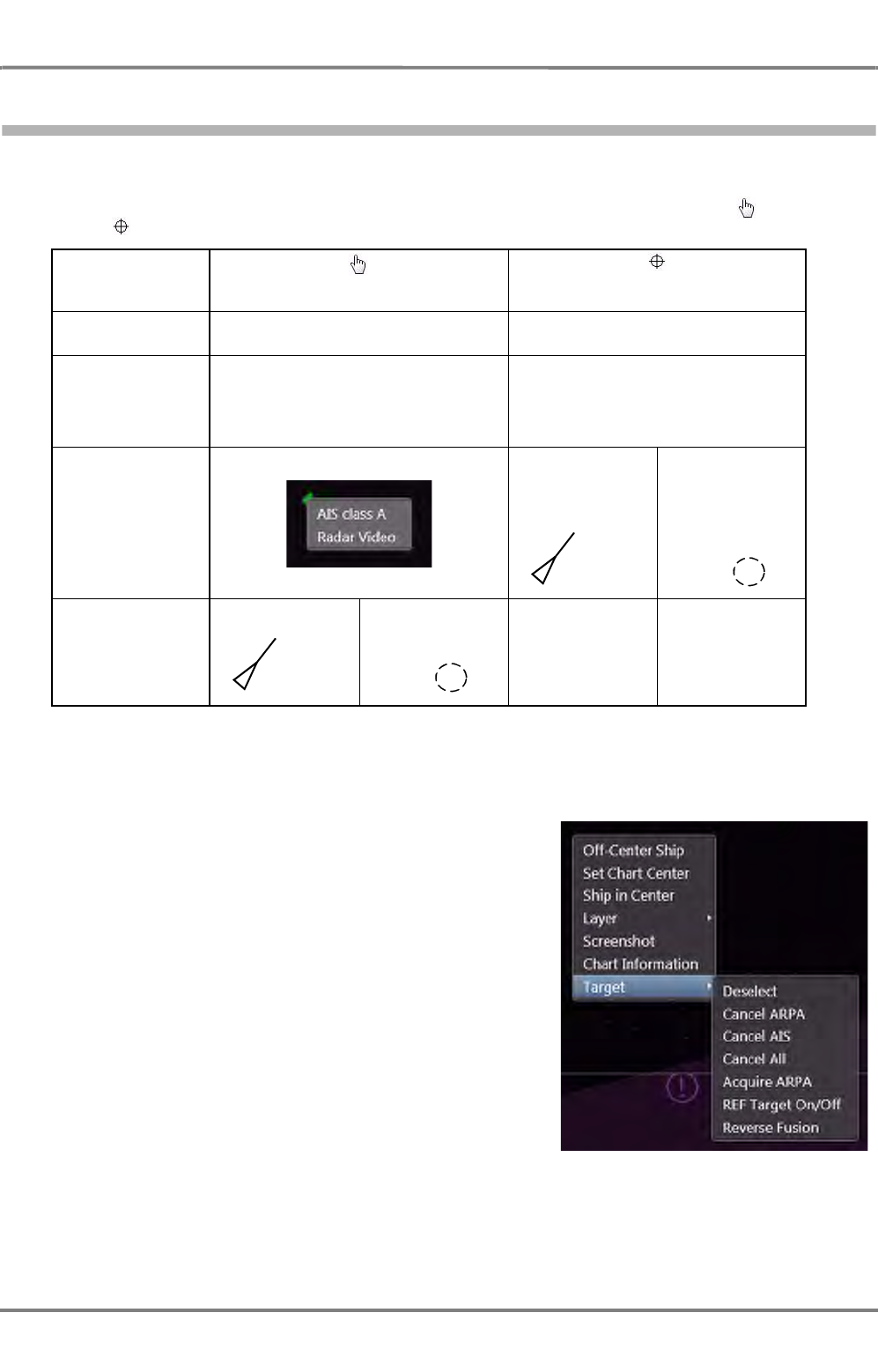
ED 3100 G 110 / 02 (2011-10)
Operating Instructions
A-7 Target Handling
A RADAR.fm / 10.11.11 A-59
NACOS Platinum
7.2 Manual Target Acquisition
Acquiring a target with DO
Move the pointer on top of the desired object. The pointer then becomes a hand or a gun site
symbol . This depends on the object underneath the pointer:
Table A / 12 Manual Target Acquisition
Acquiring/Deleting a target with MORE
Clicking on the target symbol with MORE opens the context
menu. Choose Target and select
- Deselect in order to stop the accentuation of this
target in the target list.
☞ It is not neccessary to Deselect a target before
another target can be selected, in fact it is possible to
change the selection of targets by just clicking them
with DO.
- Cancel ARPA to stop tracking the object as ARPA
target
- Cancel AIS to stop tracking the object as AIS target,
making it a sleeping target
- Cancel All to stop tracking for all targets, all activated
AIS targets become sleeping targets
- Acquire ARPA to force a radar echo to be tracked as ARPA target
- Reverse Fusion to make a fusioned target that is handled as AIS target become an ARPA target
and vice-versa
Pointer becomes a hand a gun sight
Object is not clearly identifiable, it could be an
AIS target or a radar echo clearly identifiable, it is a single AIS
target or a single radar echo
reason AIS target and radar echo appear on
the same position or are fusioned
the object is an AIS target with no
radar echo (transceiver off or bad
radar conditions) or the object is a
radar echo that carries no AIS
indication after
click with DO
make the choice...
AIS target acti-
vated radar echo with
activated ARPA
function
AIS target acti-
vated radar echo with
activated ARPA
function
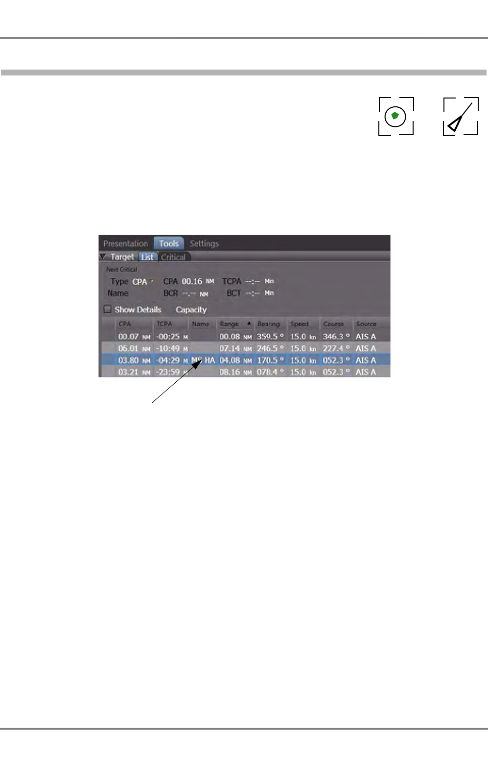
NACOS Platinum
ED 3100 G 110 / 02 (2011-10)
Operating Instructions
A-7 Target Handling
A RADAR.fm / 10.11.11
A-60
7.3 Manual Target Selection
An activated AIS target as well as an acquired or tracked ARPA target can
be selected. Then, its data are marked in the target list. To do so, click on
the activated AIS target or the acquired ARPA target with DO. The target
will be marked with a broken frame and its data are marked in the target
list with blue color. Only one target can be selected at a time on the PPI
or in the list.
Fig. A / 12 Data of the Selected Target
See chapter 7.10 on page A-68 for details about the target list.
ARPA AIS
Selected targets
Data of a selected target
accentuated in the list
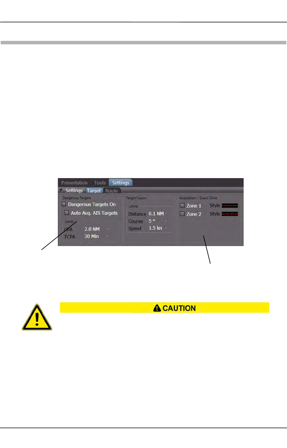
ED 3100 G 110 / 02 (2011-10)
Operating Instructions
A-7 Target Handling
A RADAR.fm / 10.11.11 A-61
NACOS Platinum
7.4 Automatic Target Acquisition
ARPA targets can be acquired automatically, sleeping AIS targets can be activated automatically as well.
There are two possibilities to acquire/activate targets automatically:
By means of the collision avoidance computation for dangerous AIS targets
- The collision avoidance computation observes every AIS target whose data are received continu-
ously. For any of those targets, the closest point of approach (CPA) and the time until the CPA is
reached (TCPA) are computed and compared with operator-defined limits. If the CPA and TCPA
values of a target fall short of the limits, the target is activated (AIS) and the Dangerous Target
alarm is raised. See also nest chapter for details.
By means of the acquisition/guard zones for radar and AIS targets
- Two of those zones can be switched on in order to perform automatic target acquisition/activation
of ARPA and AIS targets. Any radar echo and AIS target that enters one of the zones will be
acquired/activated and an alarm is raised.
Automatic target acquisition and tracking are ensured only if the radar video is OK, i.e. if
it is adjusted in the same way as would also be necessary for visual evaluation.
Under particularly unfavourable meteorological conditions, it can happen even with an
optimum setting of the radar that targets in the radar video cannot be detected automat-
ically.
Settings for collision
avoidance computa-
tion, i.e. Dangerous
Targets
Settings for Acquisi-
tion/Guard Zones
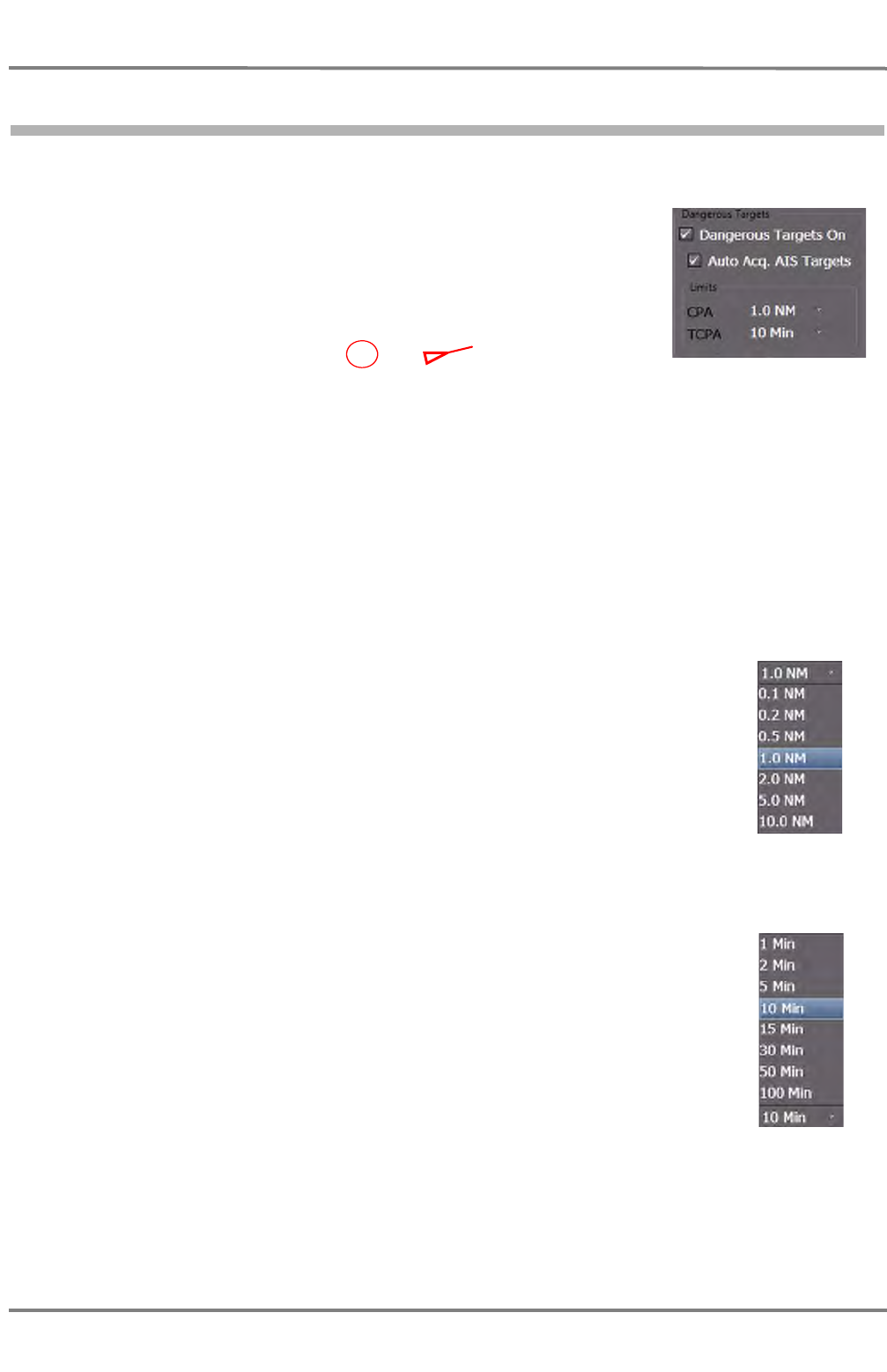
NACOS Platinum
ED 3100 G 110 / 02 (2011-10)
Operating Instructions
A-7 Target Handling
A RADAR.fm / 10.11.11
A-62
7.5 Settings for Dangerous Targets
Dangerous Targets On
With this function activated, targets tracked by the ARPA and also AIS
targets can automatically be marked as dangerous targets by the auto-
matic collision avoidance computation if their CPA/TCPA data fall short of
the limits set in the Limits group. As a result,
- the Dangerous Target alarm appears,
- the target which has caused the alarm is indicated on the PPI by
means of the flashing symbol or ; if a sleeping AIS
target has caused the alarm, that target is automatically activated
beforehand. The flashing of the symbol stops after the alarm Dangerous Target for the appro-
priate target has been acknowledged. The alarm is kept in the alarm list as long as one dangerous
target is present.
Auto Acquire AIS Targets
In particular cases, it might be required to prevent AIS targets from being acquired by the collision avoid-
ance computation, for example to avoid unnecessary alarms in port or at other berths caused by too
many AIS targets. In this case the checkbox AUTO ACQ AIS Targets must be cleared.
☞ As long as AUTO ACQ AIS Targets is activated, even sleeping targets not being selected for display
are reckognized as Dangerous targets automatically. See chapter 3.5.2 on page III-60 for details.
Limits-CPA
The limit for the distance to the closest point of approach of a target can be set here.
If a target gets closer then the set limit, it is automatically marked as dangerous
target and the alarm Dangerous Target is raised.
Limits TCPA
The limit for the time to closest point of approach of a target can be set here. If the TCPA of a target
gets shorter then the set limit, it is automatically marked as dangerous target and the alarm Dangerous
Target is raised.

ED 3100 G 110 / 02 (2011-10)
Operating Instructions
A-7 Target Handling
A RADAR.fm / 10.11.11 A-63
NACOS Platinum
Prerequisites for the Collision Avoidance Computation in case of AIS Targets
The collision avoidance computation can be performed only if the relative speed between own ship and
the target is known. This must be determined from the speed vector over ground (COG, SOG) received
from the AIS target and from the own speed vector over ground. The own speed vector over ground is
mainly determined from the Bottom Track data of the selected speed sensor; otherwise, it is deter-
mined with the aid of the COG/SOG of the selected position sensor.
If an AIS target is not transmitting COG and SOG, no collision avoidance computation takes place for this
target. Therefore, the target cannot be acquired automatically. If it is already being tracked, no
Dangerous Target alarm occurs in the case of a dangerous approach. The symbol of this AIS target is
displayed dashed.
If, because of missing data or caused by sensor selection, the own speed vector over ground cannot be
determined, then for all AIS targets the collision avoidance computation and the Dangerous Target
alarm does not take place. The symbols of all AIS targets are then displayed dashed. Three minutes after
the occurrence of this situation, the AIS No CPA Alarm, SOG Lost alarm appears
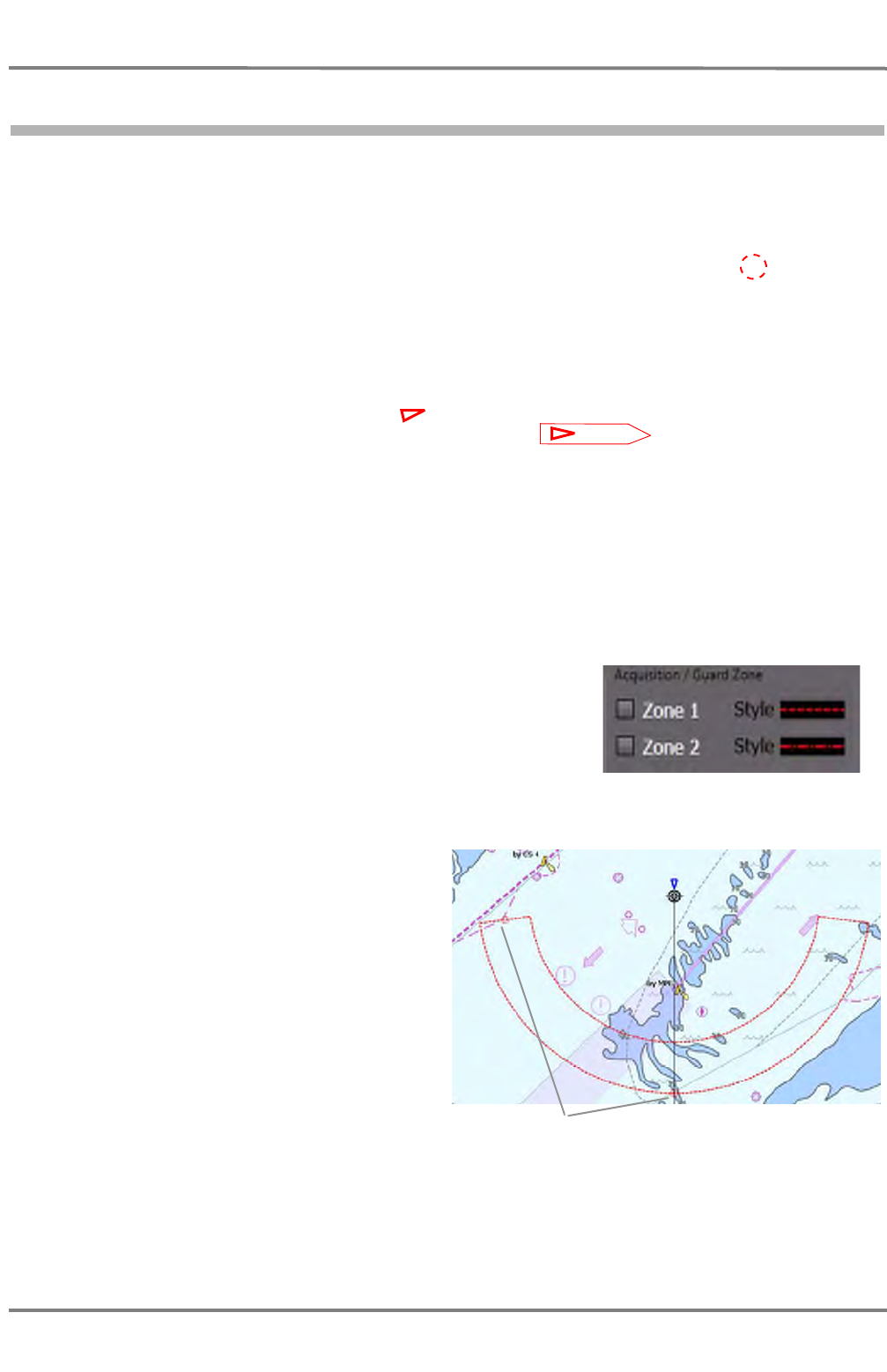
NACOS Platinum
ED 3100 G 110 / 02 (2011-10)
Operating Instructions
A-7 Target Handling
A RADAR.fm / 10.11.11
A-64
7.6 Settings for Acquisition/Guard Zones
In the case of automatic target acquisition by means of acquisition/guard zones, the radar evaluates all
radar echoes and sleeping AIS targets appearing in the acquisition/guard zones.
If the radar echo appears at a certain position at least six times during ten revolutions of the antenna,
it is evaluated as an ARPA target. If the echoes do not belong to a target already being tracked, the
position is treated as an acquired target and is marked with the flashing symbol . The Target
Auto-Acquired alarm appears, or - if the target has already been tracked when it entered the acquisi-
tion/guard zone - the Target Entered Guardzone alarm appears. After acknowledgement of the alarm,
the automatic target tracking begins.
If a sleeping AIS target enters the region of a switched-on acquisition/guard zone, it is activated auto-
matically, afterwards
- it is marked with the flashing symbol or if the function AIS True Scaled Outline is activated
the AIS target can be shown with the true scaled outlines
-the Target Auto Acquired alarm appears, or - if the target has already been active when it
entered the acquisition/guard zone - the Target Entered Guardzone alarm appears.
If there are already 95% of the maximum number of ARPA targets or 95% of the maximum number of
AIS targets being tracked or acquired, the Check ARPA/AIS Target Capacity warning appears. In this
case, at least one unimportant target must first be deleted before another target can be acquired.
If there are already 100% of the maximum number of ARPA targets or 100% of the maximum number
of AIS targets being tracked or acquired, the ARPA/AIS Target Capacity Exceeded alarm appears.
In this case, at least one unimportant target must first be deleted before another target can be acquired.
Two independent acquisistion/guard zones can be switched on in
order to acquire targets automatically.The acquisition/guard zone
is switched on and off by checking the controls Zone 1 or
Zone 2.
☞ If the acquisition/guard zone is switched off, automatic target
acquisition does not take place any longer. Targets already
being acquired or activated will be tracked further on.
Setting the Range of the Acquisition/
Guard Zone
Example shown for Guard Zone 1: Click on
the arc that defines the acquisition/guard
zone and use the small handle to drag the
zone to the desired size.
☞ The outer limit can be set to a range
value between 1.5 NM and 20 NM.
Setting the Angle of the Acquisition/
Guard Zone
Click on the angle line that defines the acqui-
sition/guard zone and use the small handle to
drag the zone to the desired angle.
☞ The angle can be set to a value between 5° and 360°. The setting takes place relative to the
heading direction, i.e. the acquisition/guard zone turns with the ship’s heading.
Handles
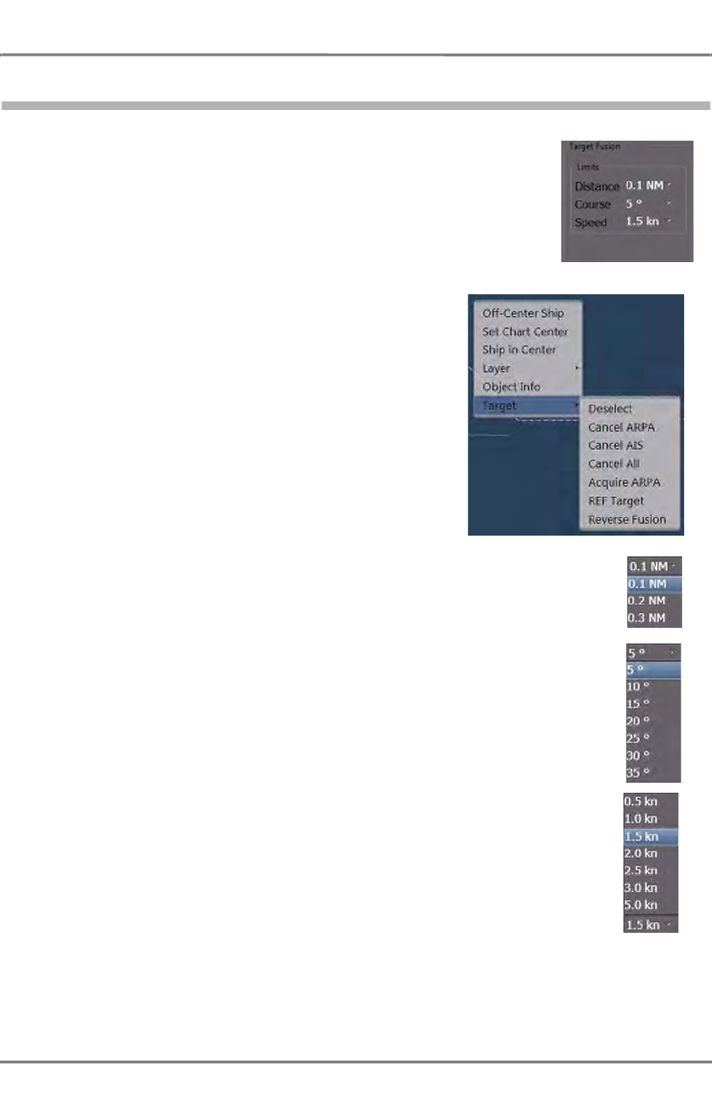
ED 3100 G 110 / 02 (2011-10)
Operating Instructions
A-7 Target Handling
A RADAR.fm / 10.11.11 A-65
NACOS Platinum
7.7 Target Fusion
An ARPA target and an AIS symbol may represent the same object. In order
to determine if this is the fact, ARPA and AIS data for distance, speed and
course are compared. If the difference in data are within pre-set limits, the
targets will be associated if this function is activated. In this case, only one
of the symbols is shown. Anyway, both targets will be continuously tracked.
The blanked-out symbol will appear again automatically if the differences in
data exceed the pre-set limits.
The limits required for this function are set here.
It is possible to define the priority for showing an object as
ARPA or AIS targets for the case that target fusion is active for
a tracked target. This means that one of the symbols can be
suppressed on the PPI. See chapter 3.5.1 on page III-59 for
details. Additionally, it can be defined for a single selected
target on the PPI to show the suppressed symbol for a limited
period of time. For this purpose click on Reverse Fusion in the
Target context menu in the PPI.
Fusion Distance
If the distance is less than the set limit, the ARPA and AIS target are displayed
as one target.
Fusion Course
If the course difference is less than the set limit, the ARPA and AIS target are
displayed as one target.
Fusion Speed
If the speed difference is less than the set limit, the ARPA and AIS target are
displayed as one target..
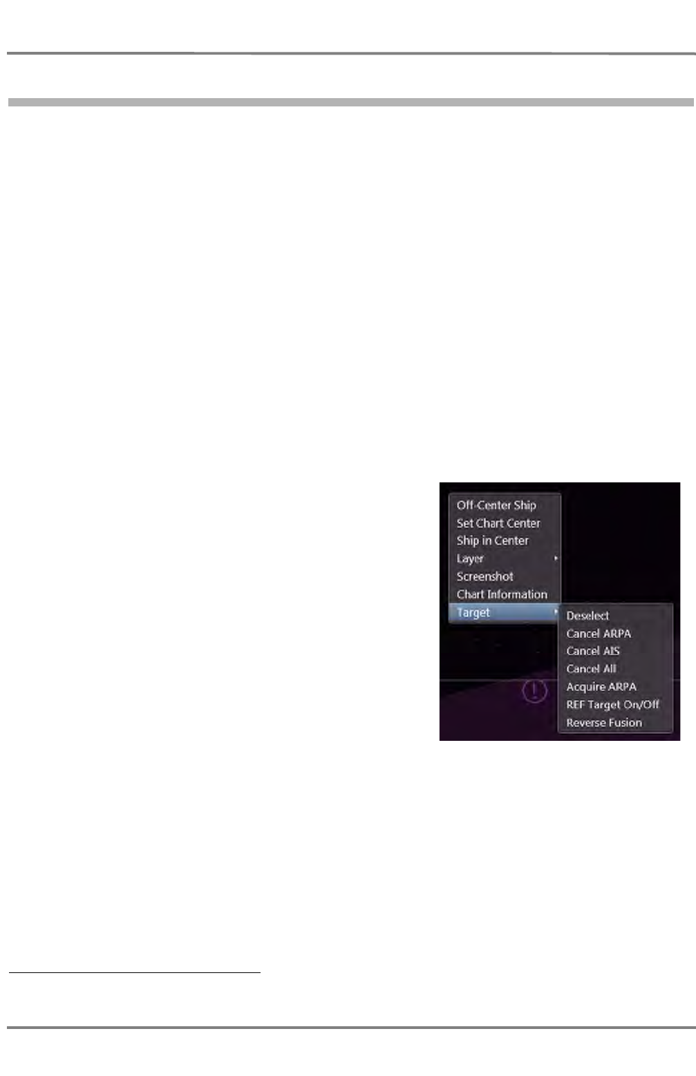
NACOS Platinum
ED 3100 G 110 / 02 (2011-10)
Operating Instructions
A-7 Target Handling
A RADAR.fm / 10.11.11
A-66
7.8 Deletion and Loss of Targets
Loss of Targets
An ARPA target is tracked automatically until
- it is deleted manually or
- it leaves the target tracking range of 24 NM or
- it is lost within the target tracking range of 24 NM.
An ARPA target is lost if, during five revolutions of the antenna, no correlation of the video can be found
by the radar, or the detection probability falls below 50%.
An AIS target is tracked automatically until
- it is deleted manually or
- it is lost.
A tracked AIS target is lost if the AIS electronics unit does not receive any more signals from that target
within the specified time 1).
Deletion of a Target
Click on the target with the MORE key, and then choose the
target type from the context menu and click on the desired
action with the DO key.
☞ If an AIS target is deleted which is also tracked in the
background as an ARPA target (See chapter 7.7 on
page A-65), the hidden ARPA symbol re-appears. If it
is to be deleted also, the process must be repeated for
the ARPA target.
☞ This procedure also works vice-versa: If an ARPA
target being tracked as AIS is deleted, the hidden AIS
symbol re-appears.
☞ For information about automatic target acquisition See chapter 7.4 on page A-61
1) The receive timeout is dependent on the navigation state and the speed of the AIS target.
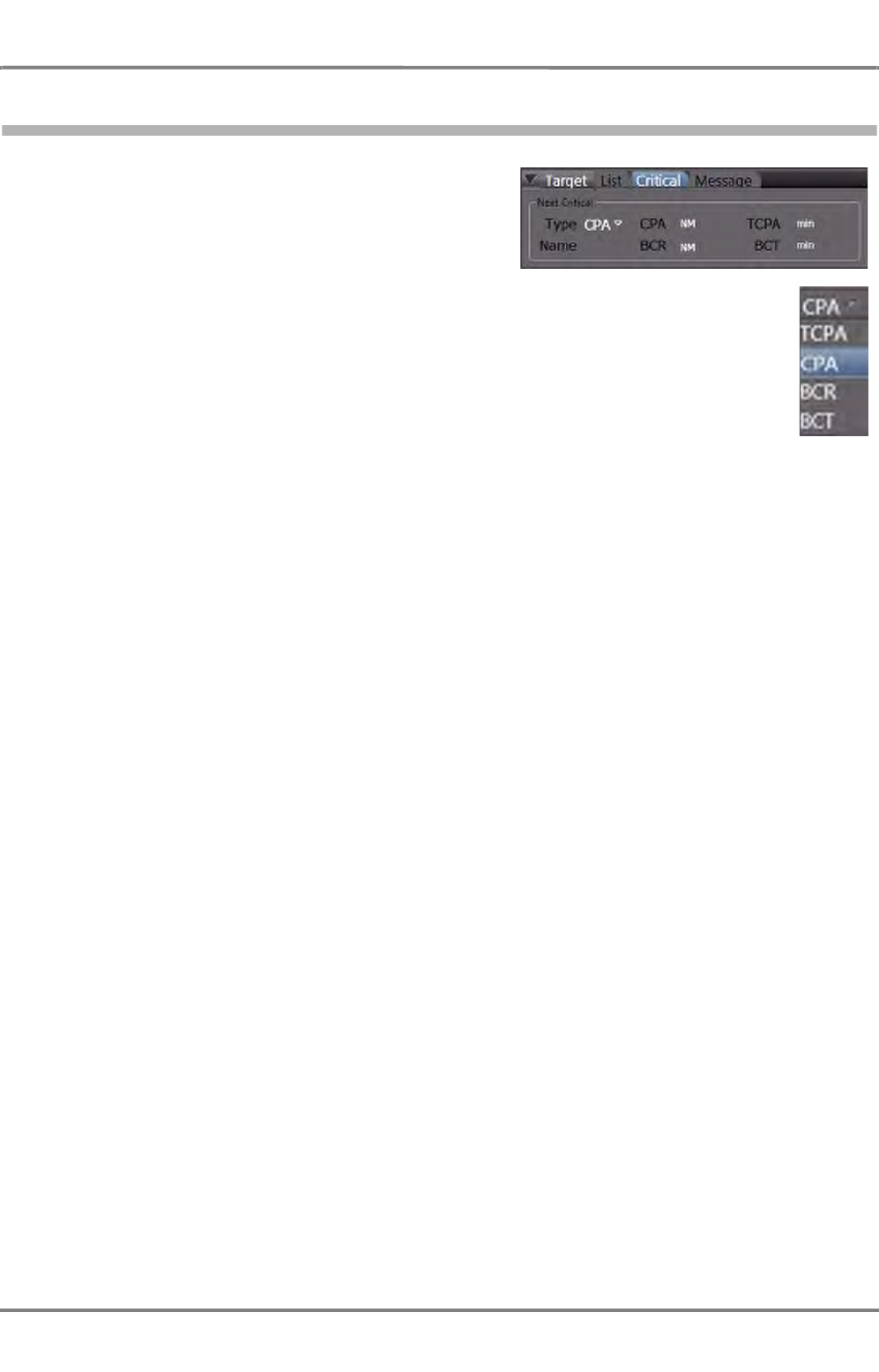
ED 3100 G 110 / 02 (2011-10)
Operating Instructions
A-7 Target Handling
A RADAR.fm / 10.11.11 A-67
NACOS Platinum
7.9 Critical Target
This group shows the most important data of the Next
Critical target in the vicinity. It can be selected which
criterion determines the most critical target. The data
are updated every second.
Type
In this list, the criterion for automatic ranking of the most critical target is selected. The most
dangerous target is always the one that has the closest distance to the own ship or the
shortest time until a dangerous situation could take place. See below for the meaning of the
abbreviations.
Name
Displays the Name of the target, if available in the received data.
CPA
The designation Closest Point of Approach means the minimum distance between the own ship and the
target at the closest point of approach.
TCPA
The Time to Closest Point of Approach means the time until the CPA is reached.
BCR
The Bow Crossing Range means the distance between the own ship and the target when the target
crosses the heading line of the own ship.
BCT
The Bow Crossing Time means the time that will pass until the target crosses the heading line of the
own ship.
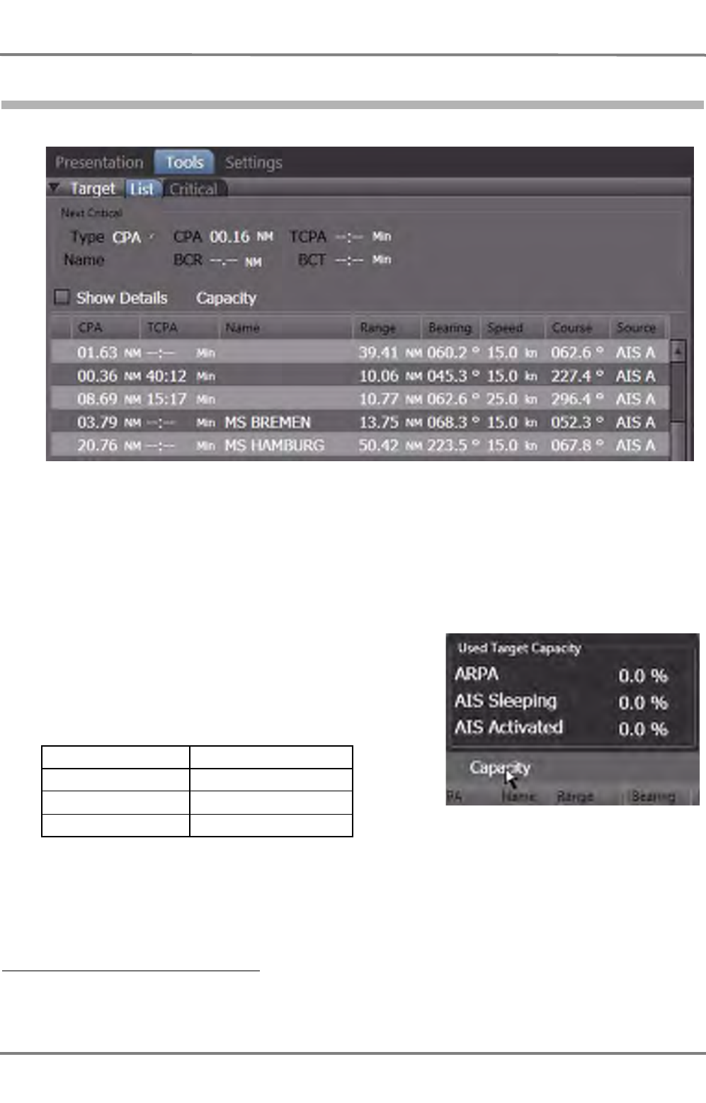
NACOS Platinum
ED 3100 G 110 / 02 (2011-10)
Operating Instructions
A-7 Target Handling
A RADAR.fm / 10.11.11
A-68
7.10 Target List
Fig. A / 13 The Target List
Additionally to the next critical (i.e. most dangerous target), a list of all targets available in the system 1)
can be displayed. The columns of the displayed table are self-explanatory, they can be sorted ascending
or descending by clicking on the appropriate title of the column. Sorting takes place in the instant of the
click, afterwards the sequence of the entries remains static, even if the values of the sort criterion
change.
If the pointer is moved on the depiction Capacity, an infor-
mation is displayed showing the percentage of memory usage
for targets. If 95% of the maximum capacity is reached, an
indication is given. If the maximum capacity is exceeded, an
alarm is given.
Maximum number of targets:
Table A / 13 Maximum Number of Targets
1) The list includes all tracked ARPA targets and all AIS targets selected for continuous display. See chapter 3.5.2
on page III-60. The most important target data can also be assessed directly in the PPI by holding the cursor on
the target symbol. See chapter 7.2 on page A-59 for details.
Type of Target Maximum Number
ARPA 40
AIS Activated 40
AIS Sleeping > 200
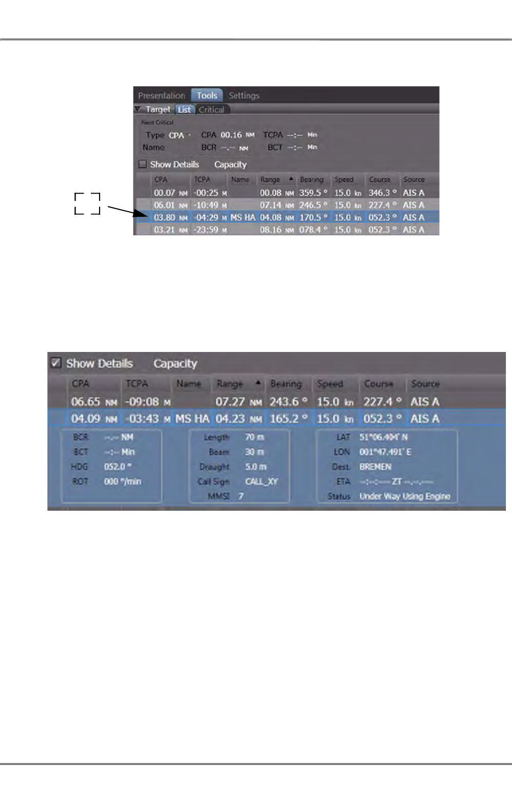
ED 3100 G 110 / 02 (2011-10)
Operating Instructions
A-7 Target Handling
A RADAR.fm / 10.11.11 A-69
NACOS Platinum
If, in the PPI a target is selected whose data is to be displayed in the list, the target´s data are accen-
tuated with blue color, possibly the list must be scrolled in order to find the marked line.:
Fig. A / 14 Marked Target
Show details
In order to display detailed data of the target (especially AIS targets), activate the Show Details
control. The small windows underneath the marked data row will display more target data as available
in the received data set.
Fig. A / 15 Target Details
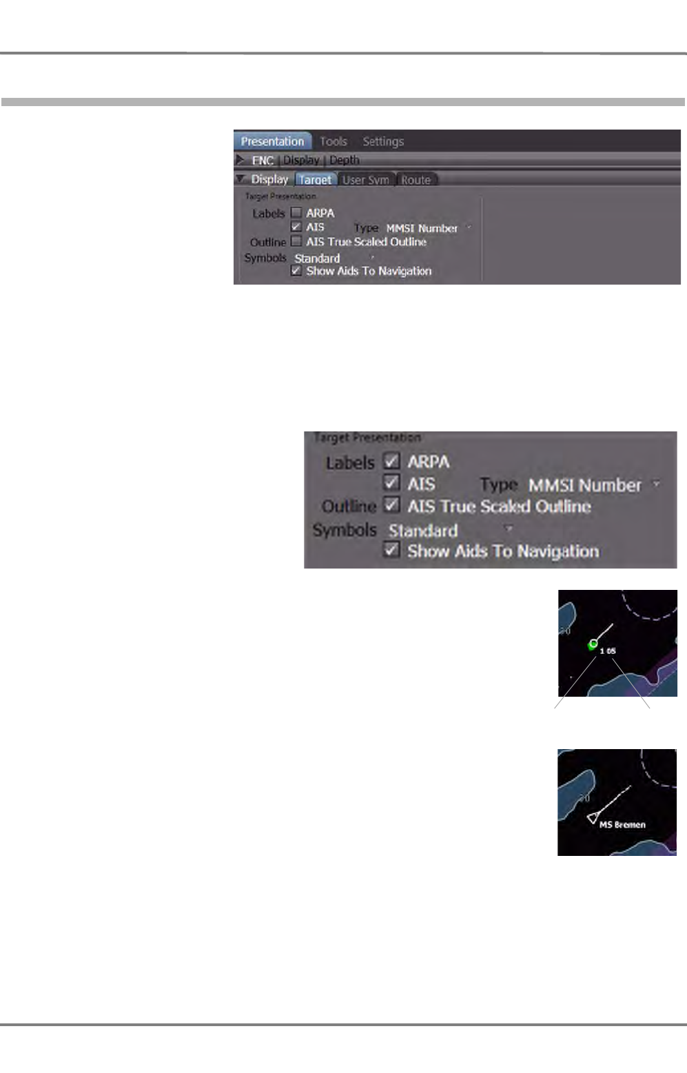
NACOS Platinum
ED 3100 G 110 / 02 (2011-10)
Operating Instructions
A-7 Target Handling
A RADAR.fm / 10.11.11
A-70
7.11 Target Display
The Target Display tab
shows information how
the symbols are
displayed on the radar
and allows to set the
system´s behaviour in
terms of displaying the
symbols.
The Display tab is divided into 2 groups:
- Target Presentation
- Own Ship Presentation
Target Presentation
For the targets, the AIS electronics
unit and the ARPA electronics of the
radar are two independent sensors
whose display functions and operating
procedures take place on one and the
same radar indicator.
Labels:
- ARPA
The target data received by the ARPA electronics of the radar can be
displayed with labels consisting of the transceiver number selected for
the MFD and the and target number.
- AIS
The target data received by the AIS electronics unit can be displayed
with labels as selected under AIS Type.
- AIS Type
- MMSI Number: Maritime Mobile Service Identity, definite
identification of the AIS system (and hence of the target).
- Call Sign: The call sign of the target.
- Ship Name: Name of the target ship.
Outline:
- AIS True Scaled Outline
In case that the AIS target delivers its ship dimensions, it is possible to
show/hide the true scaled outlines together with the AIS symbol. This is only possible if the selected
target reports the heading information and the beam of the target symbol in the PPI exceeds 7.5
mm.
Transceiver
Number Target
Number
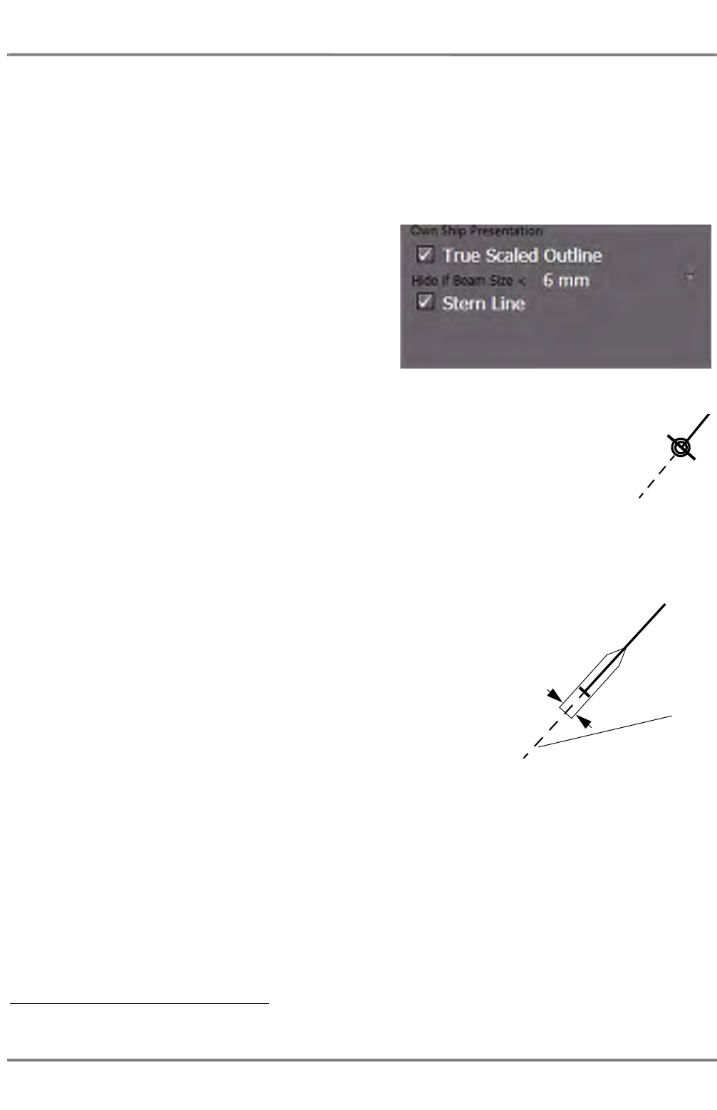
ED 3100 G 110 / 02 (2011-10)
Operating Instructions
A-7 Target Handling
A RADAR.fm / 10.11.11 A-71
NACOS Platinum
Symbols: Standard / Large
it can be selected to show Standard or Large AIS and ARPA target symbols.
Show Aids to Navigation
Aids-to-Navigation are virtual navigation marks which are reported by the AIS system. For their
display, the same symbols are used as for the electronic chart of type ENC. In addition, they are
marked by means of a blue circle having its centre at the position of the Aid-to-Navigation.
Own Ship Presentation
Minimized Symbol
The minimized own ship symbol consists of the Heading line and the Beam line
surrounded by two concentric circles.
True Scaled Outline
In the smaller ranges 1) it is also possible to show the own ship true
to scale with length and beam size parameters as stored in the ship
configuration data. The True Scaled Outline cannot be displayed in
larger ranges.
- Hide if Beam Size < 3 / 6 mm
Hides the True Scaled Outline of the own ship on the PPI if
the beam size is displayed smaller than 3 / 6 mm.
Select 3mm if you want to see the true scaled ship in the larger
ranges also.
Stern Line
This extension of the heading line in the backward direction is
displayed as far as the edge of the PPI and can be switched on if
necessary.
Vector, Plots and Prediction
Depending on the settings in the permanent area the own speed vector, a path prediction and the past
position plot can additionally be displayed together with the own ship symbol. See chapter 3.3 on page
III-49 for details. Settings for vectors, trails and plots made there are also valid for the presentation of
targets.
1) Normally (depending on the size of the ship) 1.5 or 0.75 NM and below, if 3mm is selected.
Minimized symbol
Beam size
Ship symbol with true
scaled outline
Stern line
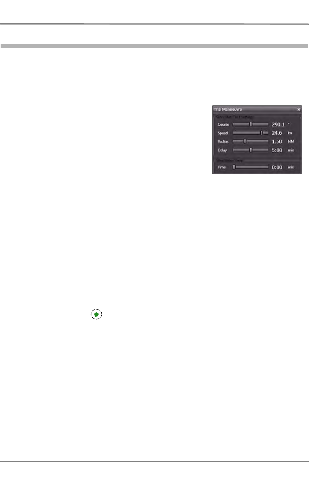
NACOS Platinum
ED 3100 G 110 / 02 (2011-10)
Operating Instructions
A-7 Target Handling
A RADAR.fm / 10.11.11
A-72
7.12 Trial Manoeuvre
Trial manoeuvres are needed mainly for collision avoidance. In this process, a planned manoeuvre of the
own ship is simulated and the effect of this manoeuvre on the targets being tracked or plotted can be
checked in the PPI or in the chart area.
Before starting the manoeuvre simulation the present values for heading, course and speed as well as
the complete currently valid target scenario is taken as a start point 1).
The trial manoeuvre can be specified in an associated dialog by
- simulation of a course change, including the radius to be used
by the ship during the manoeuvre,
- the period of time up until the beginning of the simulated
manoeuvre (the Delay) and by
- simulation of a speed change at the instant of the manoeuvre.
The simulation itself is started when the Time bar at the bottom
of the dialog is operated.
There are two vector modes available, the Relative and the True
Trial Manoeuvre:
- The manoeuvre can be observed with relative or true vectors. As during normal operation, the
vector mode is to be set in the Vector & Trails group. This setting will also have an effect on the
trails and the past position plots before the manoeuvre function is started.
- In both of the vector modes, the manoeuvre radius that can be set and the acceleration 2) for the
set speed-changes are taken into account additionally to the planned course change.
- At any time before or during the simulation, you can change between T and REL manoeuvre vector
mode, without changing other simulation parameters.
☞ The target tracking / plotting and the manual and automatic target acquisition are not interrupted
during the execution of a manoeuvre, but no new sleeping AIS targets can be activated manually.
This means also that the target list under Tools > Targets > List at all times displays the currently
valid data of the target tracking process and not the trial manoeuvre data.
☞ Contrary to targets already being tracked by the ARPA, radar targets which are in the state of
"under evaluation" (i.e. being in "acquisition status) will not be taken into account for the trial
manoeuvre.
☞ As long as the Trial Manoeuvre is active, the Dangerous Targets function (ARPA and AIS) is auto-
matically On, independently of the settings under Settings > Targets > Dangerous Targets
and AUTO ACQ AIS Targets respectively.
☞ It is recommended to use the trial manoeuvre function in relative vector mode in order to evaluate
the change of the relative target data first.
If the true vectors are used, it is recommended to select a speed sensor with water stabilisation
(Set the stabilisation ,REF to Water in the Vector & Trails group).
1) Start values for own ship's heading, course and speed are taken from the values shown in the sensor displays
on the permanent area. The course and speed data are depending on the selection of the CCRP.
2) The min. and max. radius and the acceleration behaviour of the ship are entered at service level during setting-
to-work.
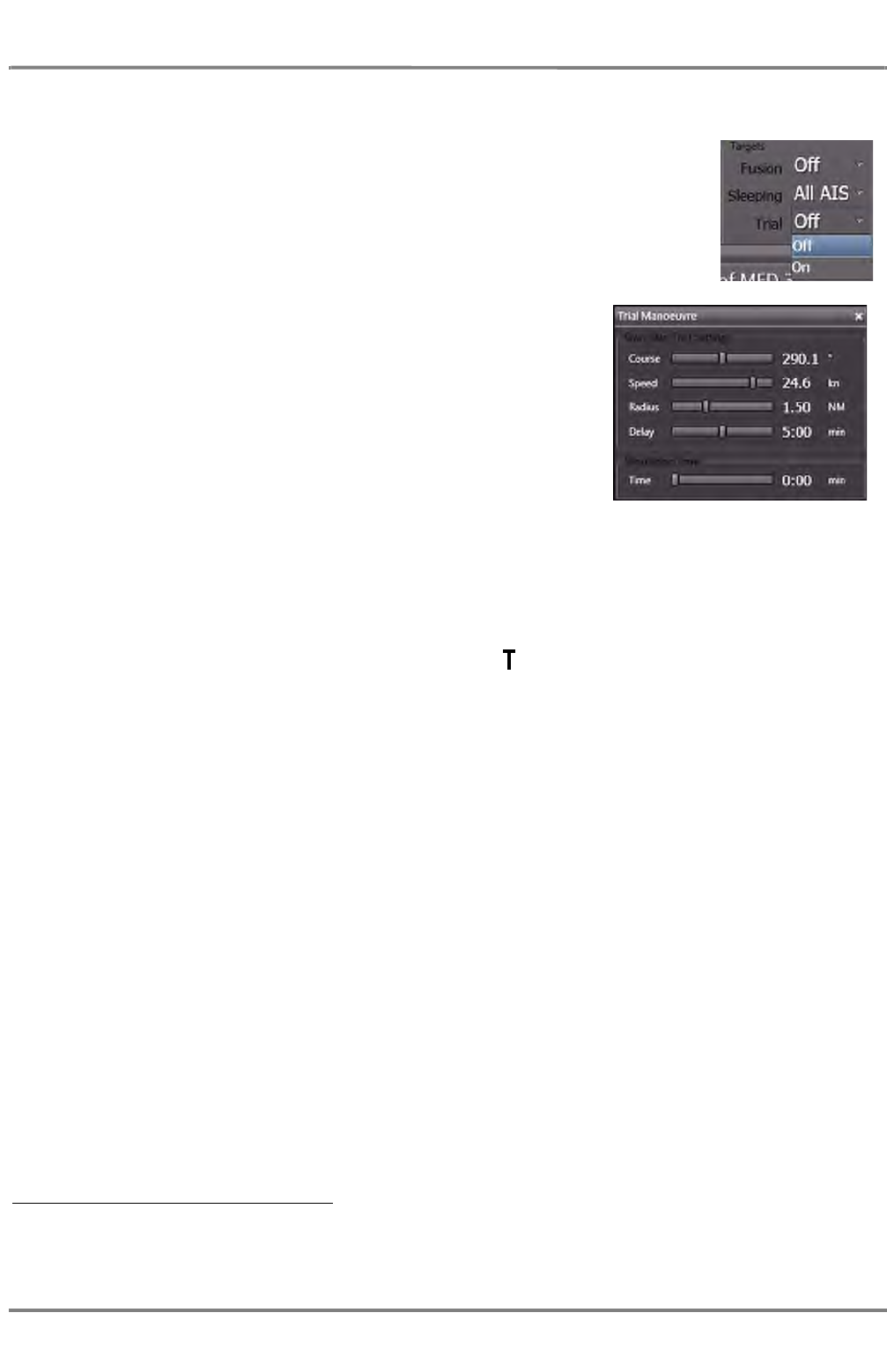
ED 3100 G 110 / 02 (2011-10)
Operating Instructions
A-7 Target Handling
A RADAR.fm / 10.11.11 A-73
NACOS Platinum
Switching On the Trial Manoeuvre Dialog in REL Vector Mode
- Switch to REL in the Vector &Trails group on the permanent
area.
- In the Targets group choose On for the Trial control.
In the Non-permanent area, the Trial Manoeuvre dialog window
appears, with the following data:
- Course: The currently existing course (the course is changed
when the ship is turning) 1)
- Speed: The currently existing speed (the value is constant
and taken as start speed) 1)
- Radius: The radius with which the manoeuvre is to be simu-
lated. If the dialog has not been used before, the minimum
radius is displayed, otherwise it shows the last used radius.
- Delay: 0 minutes. Can be set for simulation of a delayed start of the manoeuvre.
- Time: 0 minutes. Must be set for simulation of the time instances during the manoeuvre.
The following changes occur in the PPI or chart area after activation of the trial manoeuvre function 2):
- In the lower region of the application area a large symbol is shown to draw the operator's atten-
tion to the fact that the trial manoeuvre display is switched on and that after starting the simulation
by changing the time slider, consequently the symbols and vectors of the targets are no longer
displayed in accordance with the real situation that actually exists at that time.
- The vector display (of the targets) must be switched on during observation of the manoeuvre.
- The vectors and the video trails (if any exist), are displayed relative and
- the own ship is shown without vector but always with the correct present heading line.
- Past position plots are not displayed during the trial manoeuvre, but (if Plot is in the switched on
state) they are continuously built up in the back-ground and are visible again as soon as the trial
manoeuvre is ended.
☞ Because the currently existing values were taken over, no manoeuvre has been simulated yet. As
long as the Time bar remains at zero position the display content is still corresponding to the real
situation.
Setting the Trial Manoeuvre in REL Vector Mode
In case the vector display during the trial manoeuvre is a relative display, a collision course can be recog-
nised from the fact that the vector of a target is pointing towards the own ship symbol (constant
bearing). A manoeuvre of your own ship must be simulated which avoids this constant bearing while at
the same time fulfilling other conditions (e.g. keeping within the channel, avoiding shallow water and
obstructions, avoiding other ships, etc.).
1) The resultant value used for the display of the own ship speed vector during simulation
2) The radar video and the true or relative target trails are updated as normal and are not influenced by the
manoeuvre simulation.
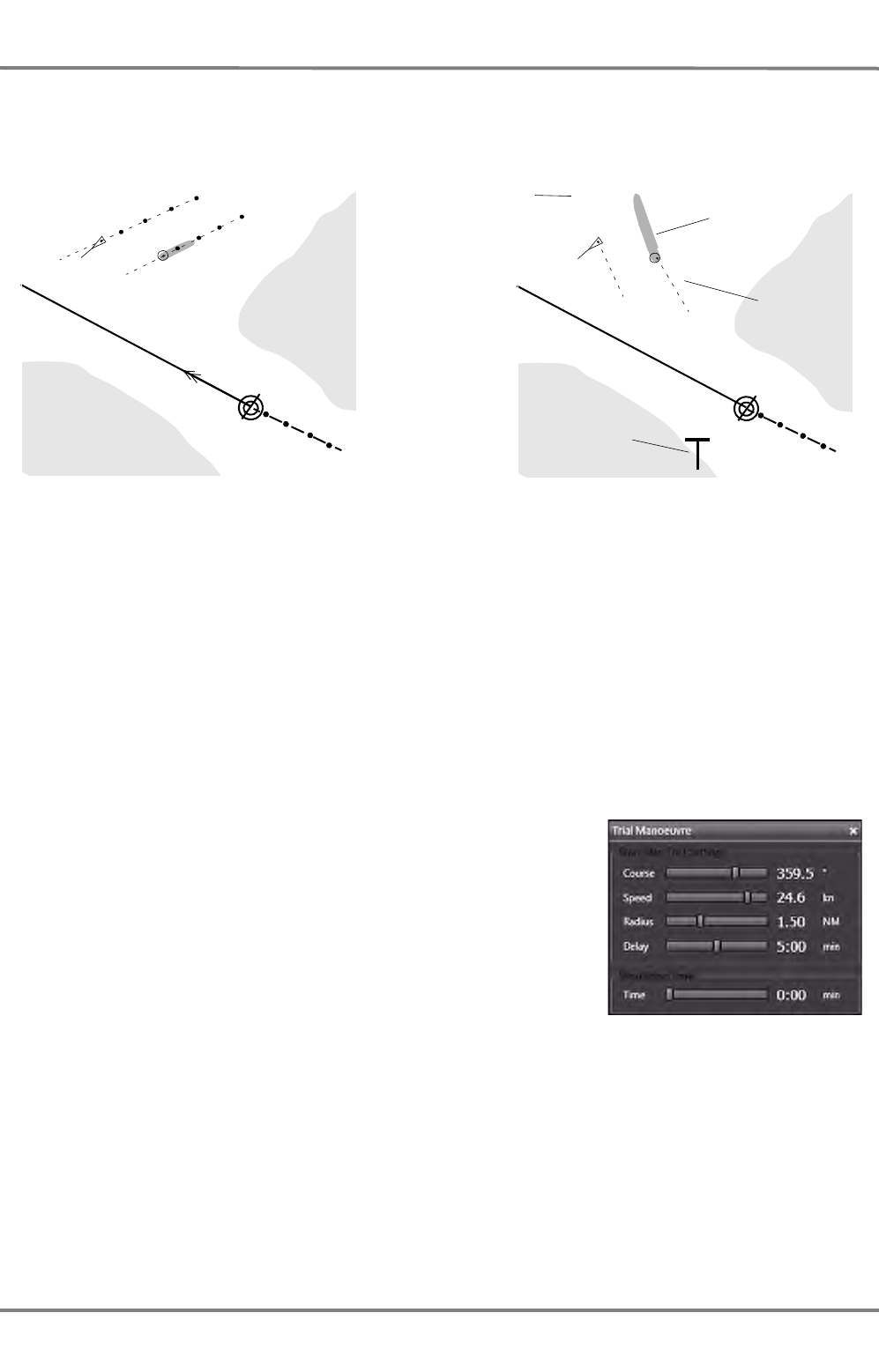
NACOS Platinum
ED 3100 G 110 / 02 (2011-10)
Operating Instructions
A-7 Target Handling
A RADAR.fm / 10.11.11
A-74
Depending on the used display range a suitable vector length should be set so that the results of the
trial manoeuvre are clearly visible.
Fig. A / 16 Vector Display in Trial Manoeuvre Mode
☞ The general screen-stabilisation and the alignment of the heading line may remain unchanged, or
can be set by the operator as required. With other words, the Trial Manoeuvre can be observed in
True or Relative Motion and in Head Up, North Up or Course up orientation.
Simulating a Course Manoeuvre
Use the Course and Radius slider to set the desired amount of
course change and the radius with which the manoeuvre is to be
simulated.
☞ During adjustment, the simulated course change is displayed in
form of a curved headline. A change of max. +/- 180° relative
to your present course can be simulated. The heading and the
present course is updated automatically if your ship is turning
during the manoeuvre simulation.
After course and radius have been set, use the Time slider to simu-
late your ship sailing along the pre-planned course change. All displayed targets will move accordingly
with their current speed and course and the change of their relative vectors will show the further devel-
opment of the scenario step by step.
The time setting can be done continuously by moving the slider or (by clicking) stepwise in 10 sec incre-
ments up to 30 min complete duration.
☞ Because of the REL Vector Mode, the relative speed vectors are rotated and change their length by
the simulated course-change. If one of the targets will change its status from dangerous to not
dangerous and vice versa, this will be shown by a change of their symbol's colour.
Display before switch-on of the trial
manoeuvre (with true vector display and
past position plots)
Display after switch-on of the (relative)
trial manoeuvre (the target on the right is
on a collision course)
Trails are
relative
Targets get
relative
vectors
Identification
marking of trial
manoeuvre
display
Past position
plots are no
longer displayed
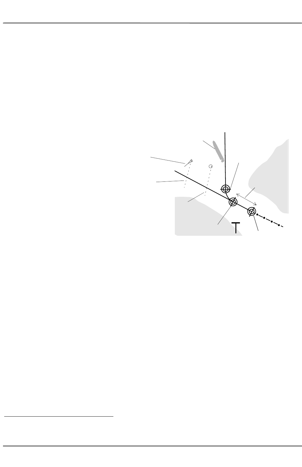
ED 3100 G 110 / 02 (2011-10)
Operating Instructions
A-7 Target Handling
A RADAR.fm / 10.11.11 A-75
NACOS Platinum
Also during the trial manoeuvre the collision calculations 1) take place, which would indicate a dangerous
target symbol in red colour as soon as the anti-collision limits are infringed.
Setting the Delay of the Simulated Manoeuvre
Use the Delay slider to set the time that is to pass before the simulated manoeuvre begins.
☞ The future situation at the point in time defined by the delay value is now displayed in form of a
modified own ship track line ahead (along the present course direction) and the previously defined
course change is shown at a distance ahead, calculated from the present speed and the delay time.
The manoeuvre simulation itself must be controlled as described above with a movement of the Time
slider or clicking into the Time bar.
Fig. A / 17 Delay in Trial Manoeuvre
If no suitable manoeuvre can be found by means of these two settings, a speed change must be simu-
lated:
Simulation of a Speed Change
Use the Speed slider to set the speed at which the ship is to travel from the beginning of the simulated
manoeuvre onwards.
☞ Because of the REL Vector Mode, the simulated course-change causes a change in the directions
and lengths of the target´s speed vectors.
Rules for the Avoidance of Collision Courses:
1. There must be no speed vector of any of the targets pointing towards the own ship symbol of the
trial manoeuvre.
2. All manoeuvres and parameter settings must take place in accordance with the collision avoidance
rules and good seamanship.
1) The collision calculations of the trial manoeuvre simulation implement the same alarm limits for CPA and TCPA as
set for the normal target tracking in the Dangerous Targets group of the Settings > Targets menu.
Relative display after setting of a trial
manoeuvre which would prevent a
collision
Distance up until
the trial
manoeuvre, as
selected with
Delay
No risk of collision
(vector shows suffi-
ciently large
passing distance
from the trial
manoeuvre posi-
tion) Trial
manoeuvre
start position
Trails are
updated in
relative mode
Heading lines and
orientation of AIS
targets remain
unchanged
Symbols moved and vectors
changed in the simulation of the
course change manoeuvre.
Radius that is set for
the trial manoeuvre
The present own
ship position

NACOS Platinum
ED 3100 G 110 / 02 (2011-10)
Operating Instructions
A-7 Target Handling
A RADAR.fm / 10.11.11
A-76
Checking the Trial Manoeuvre in True Vector Mode
In True Vector Mode, the trial manoeuvre is displayed with true vectors for the targets and own ship.
Both the radius planned for the course change manoeuvre and the acceleration behaviour for the speed
change that is set and the delay are taken into account. All settings made in REL vector Mode can still
be changed in the True Vector Mode.
Switch-On of the True Vector Mode
The switch-over between True and REL Vector Mode is performed in the Vector & Trails group by
clicking on the REL or T selection button.
☞ It is possible at any time to switch between the two vector modes without any loss of data or infor-
mation. In both modes the same state of the manoeuvre is shown on the screen, if no other trial
manoeuvre setting is changed.
☞ It is recommended to use the true trial manoeuvre together with a speed sensor giving speed
through water. This can be selected as in normal operation mode of the system by selecting REF
Water instead of REF Ground in the Vector & Trails group.
☞ Whenever it is not sure that the calculated data or the used sensor data are correct and stable, it
is recommended to perform the Trial Manoeuvre in REL mode (see above).
As a result of the switch-over into True Vector Mode, the following changes occur:
- True vectors and true target trails are displayed. Past positions of targets remain invisible as long
as the Trial Manoeuvre is running.
- Own ship and all targets are shown at their currently existing positions with their true vectors as
long as the Time value is set to 0:00 min.
- The trial manoeuvre line is displayed. It represents the track on which the ship would perform the
simulated manoeuvre. The Radius displayed in the manoeuvre dialog is taken into account for
calculation of the course change.
The simulated manoeuvre-settings can now be changed in the same way as described above for the rela-
tive manoeuvre mode:
Use the Course, Speed, Radius or Delay slider to set the desired parameters with which the
manoeuvre is to be simulated and move the Time slider to see the future development of the scenario.
Checking the Trial Manoeuvre
By means of Time, the instant of time that is to be considered can be set:
- Click on the Time bar slider and, with the trackball, vary the time instant that is to be displayed
- or -
- click before the slider to produce 10 sec time increments stepwise.
By continuous variation, a synchronised display of the simulated own ship positions and target positions
takes place. If, for all time values, an adequate distance between own ship symbol and the target symbol
is displayed, the trial manoeuvre will not show a dangerous approach.
Also during the true trial manoeuvre the collision calculations 1) take place, which would indicate a
dangerous target symbol in red colour as soon as the anti-collision limits are infringed.
If necessary, any of the trial manoeuvre settings can now be changed and the check can be repeated.
1) The collision calculations of the trial manoeuvre simulation implement the same alarm limits for CPA and TCPA as
set for the normal target tracking in the Dangerous Targets group of the Settings > Targets menu.
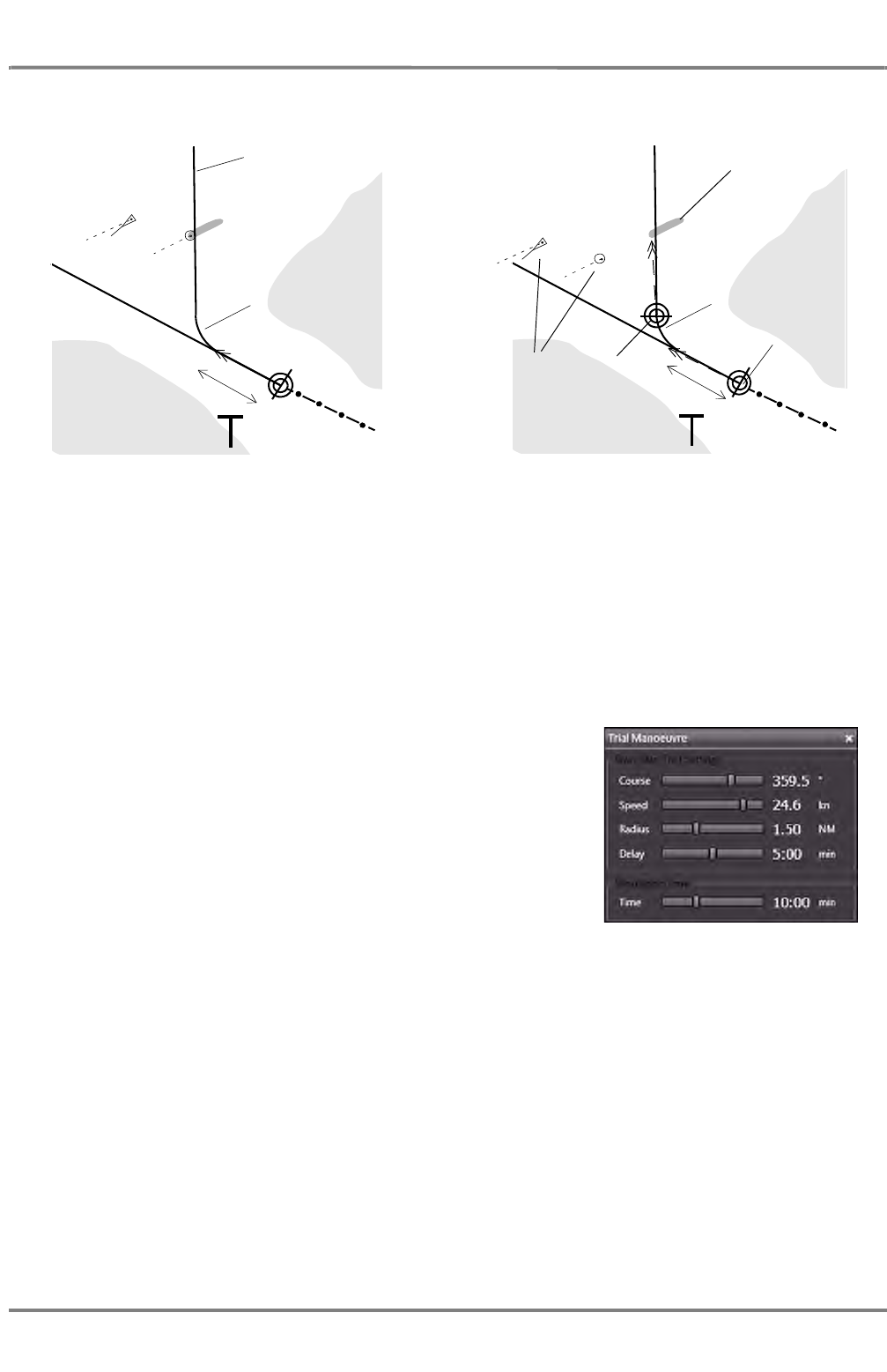
ED 3100 G 110 / 02 (2011-10)
Operating Instructions
A-7 Target Handling
A RADAR.fm / 10.11.11 A-77
NACOS Platinum
Fig. A / 18 Checking the Trial Manoeuvre
Switching Off the Trial Manoeuvre Display
Switching off is performed by pressing the Close icon of the
Trial Manoeuvre dialog window.
The trial manoeuvre can also be switched off in the Targets
group on the permanent area by selecting Trial Off.
Display after switch-over to True Vector
Mode
Radius that is
set for the trial
manoeuvre
Check by variation of the Time
input
Radius that is set for
the trial manoeuvre
The present
own position
(own ship
symbol and
true vector)
Trial manoeuvre
line defined by
course
Future positions after
the time entered
with the Time slider
Delay Delay
Trails are updated in
True mode
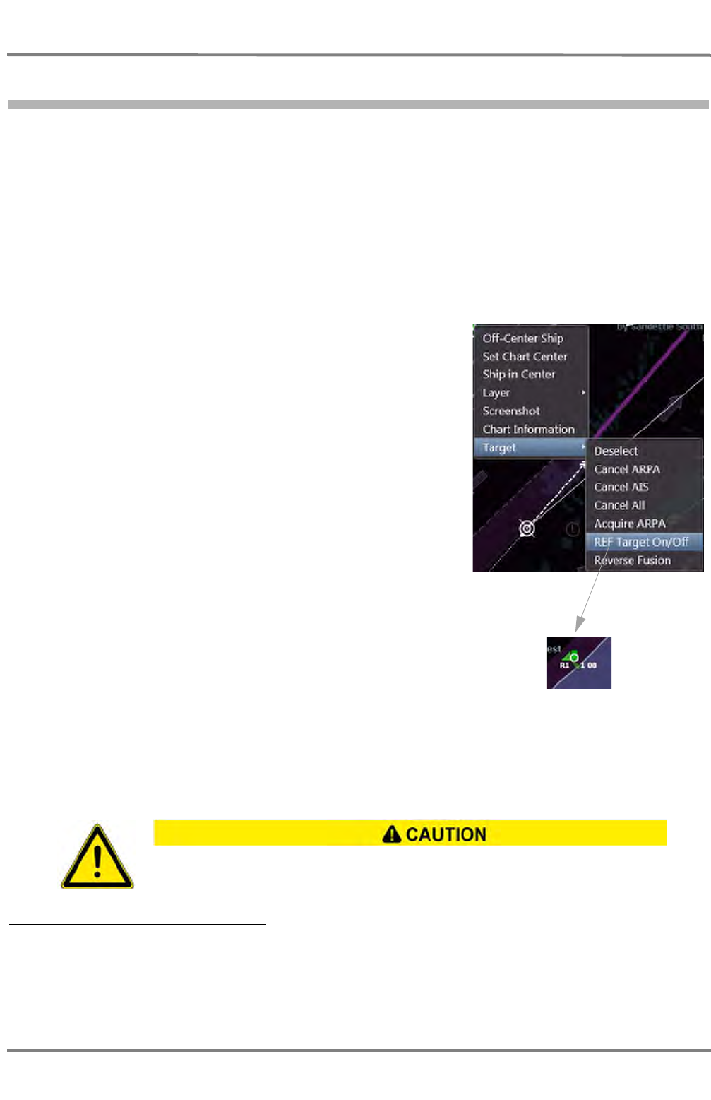
NACOS Platinum
ED 3100 G 110 / 02 (2011-10)
Operating Instructions
A-7 Target Handling
A RADAR.fm / 10.11.11
A-78
7.13 Reference Target Tracking
If at least one fixed ARPA target 1) is selected as a reference target, the radar can determine the own
ship's speed vector with the aid of this target's relative motion. By means of this "reference target
tracking", the radar also acts as a speed sensor, and can be called up as such under REF TGT Speed
in the COG/SOG sensor selection menu. It is recommended to use more than one target for own course
and speed calculation in order to create as stable values as possible.
The resultant course and speed is calculated by averaging the relative speed data evaluated from all
selected reference targets.
Selecting a reference target:
Click on the fixed ARPA target with the MORE key, and then click
on REF Target On/Off (with the DO key) in the context menu.
The first reference target is given an R1 as its target label. If
there is more than one reference target defined, all reference
targets are given an independent sequential number in addition
to the letter R as prefix.
Cancelling the selection: Click on the reference target with
the MORE key, and then click on REF Target On/Off (with the
DO key) in the context menu.
☞ Up to five reference targets can be selected.
☞ The speed input "Reference Target Tracking" is treated as
a ground stabilized speed sensor (speed over ground),
displayed as COG/SOG data, but it is never used for calcu-
lation of relative course and speed of AIS targets (according
to the IMO rules) 2).
☞ The loss of a tracked reference target triggers the Lost
Target alarm. See chapter 7.8 on page A-66.
If the last reference target is lost, a new speed sensor must be selected. See chapter 3.2.2 on page III-
35.
If no new speed sensor is selected in time, the Speed Invalid alarm is triggered for the selection of
another speed sensor by the operator.
1) A fixed target is a tracked radar echo of a fixed object like a buoy, a light house, a landmark etc. In the true
vector mode, it shows no or a very short vector. If a moving target is selected by mistake, the own speed deter-
mined will be incorrect. To ensure accurate determination of speed, several fixed targets should be selected as
references. AIS targets cannot be selected as reference targets.
2) As long as REF TGT Speed is selected as COG/SOG input, the display of relative target data for AIS-targets is
omitted.
During reference target tracking, it shall be checked repeatedly if the selected reference
targets are still displayed as fixed targets. Loss of a tracked reference target may reduce
the accuracy of the evaluated own speed and course, whereby the true data of other
tracked targets may be deteriorated.
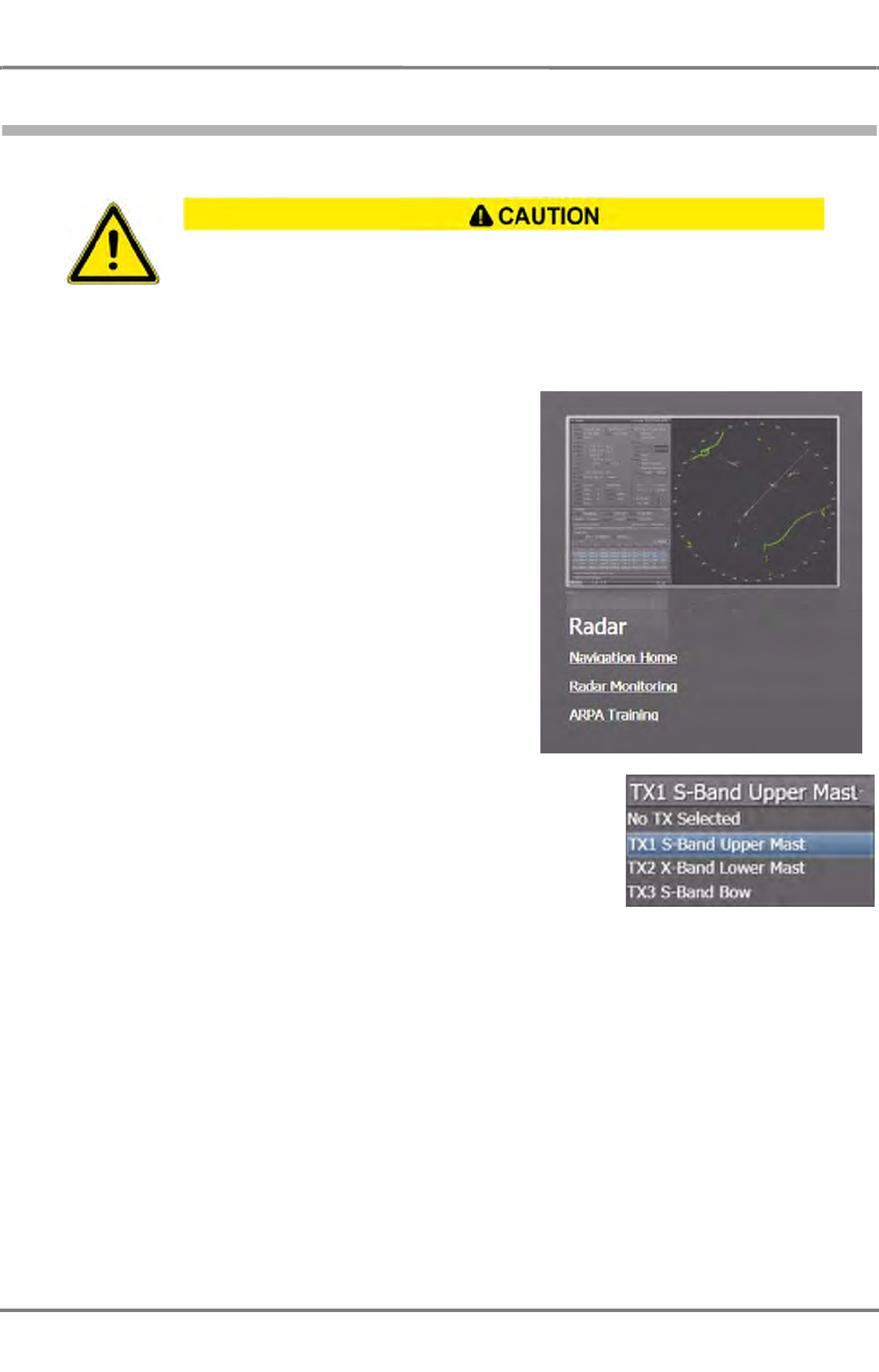
ED 3100 G 110 / 02 (2011-10)
Operating Instructions
A-7 Target Handling
A RADAR.fm / 10.11.11 A-79
NACOS Platinum
7.14 ARPA Training
By means of the ARPA function test, the overall performance of the ARPA can be assessed. This should
be done periodically.
The ARPA Training facility can be activated on the Super
Home page. Beforehand, it must be ensured that a trans-
mitter is chosen for use and at least in Stand By mode.
See chapter 5.1.1 on page A-38 for details on the trans-
ceiver selection.
As long as the ARPA Training facility is in use, the radar picture will not show echoes
received by the appropriate transceiver.
All displayed echoes are artificial. For safety, make sure to keep an eye on another acti-
vated transceiver while using ARPA Training.
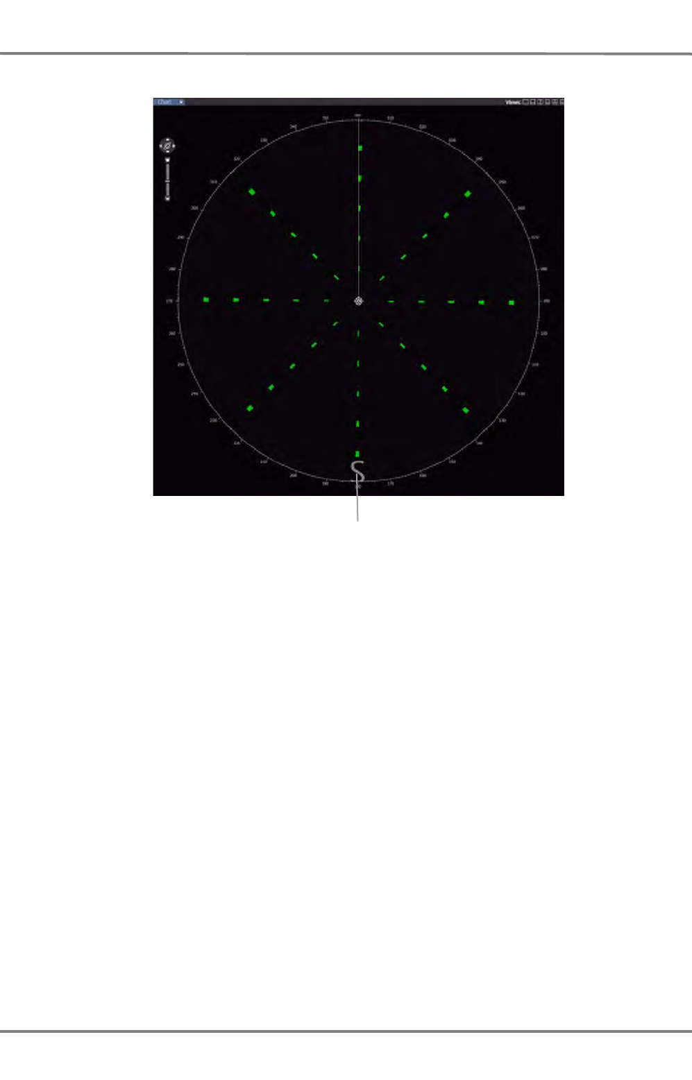
NACOS Platinum
ED 3100 G 110 / 02 (2011-10)
Operating Instructions
A-7 Target Handling
A RADAR.fm / 10.11.11
A-80
The radar picture turns into a spoke-pattern with artificial radar echoes:
Fig. A / 19 ARPA Training Display
- These echoes can be acquired manually for ARPA tracking.
- When the acquisition / guard zone is placed over one or more targets, automatic acquisition must
take place, together with the associated symbols and alarms. The targets must be tracked automat-
ically.
- All targets travel along with your own ship. Therefore, their true courses and true speeds must be
the same as your own ship's course and speed.
It can be observed whether the tracking works correctly. Furthermore, the user can observe the target
graphics and display of the ARPA data in the appropriate display windows and make himself familiar with
this function.
To turn off the ARPA Training facility, navigate to the Super Home page again and click on ARPA
Training again.
The depiction indicates that this is a simulated picture.

ED 3100 G 110 / 02 (2011-10)
Operating Instructions
A-7 Target Handling
A RADAR.fm / 10.11.11 A-81
NACOS Platinum
7.15 ARPA Malfunctions
There are a couple of possible reasons for which the ARPA cannot compute the target data correctly.
Possible alarm messages:
1. Heading sensor fault: Heading Invalid or Heading Timeout
2. Magnetron Fault
3. No Headmarker
4. No Trigger
5. No Antenna Azimuth
6. No RADAR Video
For further information regarding the alarms please See chapter 2.2 on page V-11
☞ In case that the compass system is faulty, the radar goes immediately into the Head-Up mode. All
display objects and operating possibilities for which the heading information is required are no
longer shown or are inactive. All ARPA and AIS targets are deleted from the screen at once. If the
heading sensor failure is not corrected within 30 seconds, all tracking of targets is stopped. The
additional reasons for the malfunction of the ARPA calculation are listed below.

NACOS Platinum
ED 3100 G 110 / 02 (2011-10)
Operating Instructions
A-7 Target Handling
A RADAR.fm / 10.11.11
A-82
7.16 AIS Malfunctions
There are a couple of possible reasons for which the RADAR or the AIS cannot compute or transmit the
target data correctly:
- In case that the compass system is faulty, the RADAR goes immediately into the Head-Up mode and
all AIS and ARPA targets are deleted at once on the PPI. The target list for the AIS targets remains
available.
- If the UHF-Transceiver within the AIS electronics unit does not work correctly, no messages can be
received and/or transmitted.
- In case that the internal GPS receiver within the AIS electronics unit does not work correctly, the
position data of an external position sensor will be used for computation, if an external sensor is
connected to the AIS electronics unit.
Anyway, appropriate alarm messages, warnings, or indications will be raised.
Possible alarm messages, warnings or indications 1):
1. TX Malfunction
2. Antenna VSWR exceeds Limit
3. Rx Channel n malfunction
4. General failure
5. MKD connection lost
6. External EPFS lost
7. No Sensor Position in use
8. No valid SOG Information
9. No valid COG Information
10. Heading lost/invalid
11. No valid ROT Information
For further information regarding these alarms please See chapter 2.2.3 on page V-19
See chapter 1 on page F-3 for details on AIS in general.
1) The availability of the above mentioned AIS alarms depends on the maker and type of AIS electronics which is
connected to the system.

ED 3100 G 110 / 02 (2011-10)
Operating Instructions
A-8 User Symbols
A RADAR.fm / 10.11.11 A-83
NACOS Platinum
8User Symbols
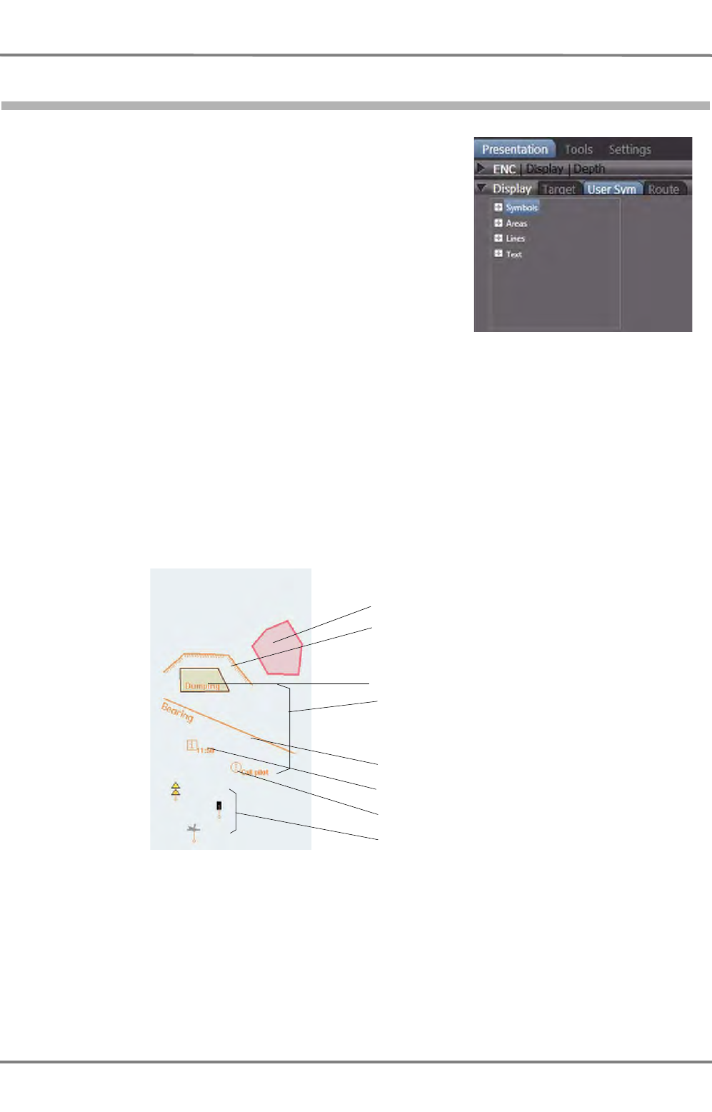
NACOS Platinum
ED 3100 G 110 / 02 (2011-10)
Operating Instructions
A-8 User Symbols
A RADAR.fm / 10.11.11
A-84
8.1 Symbols
User symbols are individual user made chart objects which
can be inserted into the chart database in order to supple-
ment the official electronic charts.
The user made symbols of different kind are stored perma-
nently in the common databases on all MFD with radar or
ECDIS functionality. Deletion of selected symbols is the
only method to remove User Symbols from the database.
The common database of the User Symbols can be stored
on external memory devices like USB-Memory sticks. See
chapter 2.9 on page H-13 for details.
The User Symbols panel of the Display expander provides
different object categories:
- Symbols (position fix, anchorage area, buoys and beacons, lights, landmarks, platforms, radio
stations and wrecks etc)
- Areas (highlighted danger areas and feature areas)
- Lines (safety lines, feature lines and clearing lines)
- Events and Text (for free text information and cautions)
The following figure shows examples of user symbols:
Fig. A / 20 User symbols on the electronic chart
Switching on and off the display of User Symbols: In Presentation > Display > User Sym, or by a
MORE click into the PPI(Chart area under Layer > User Symbols)
Danger highlight (red)
Own safety line (orange; the
hatching points towards the
unsafe area)
Feature area (ochre, brown)
Feature line (orange)
Text note, information
Text note, caution
Symbols (examples)
Names and notes are
displayed if the display
of the Text Labels is
switched on
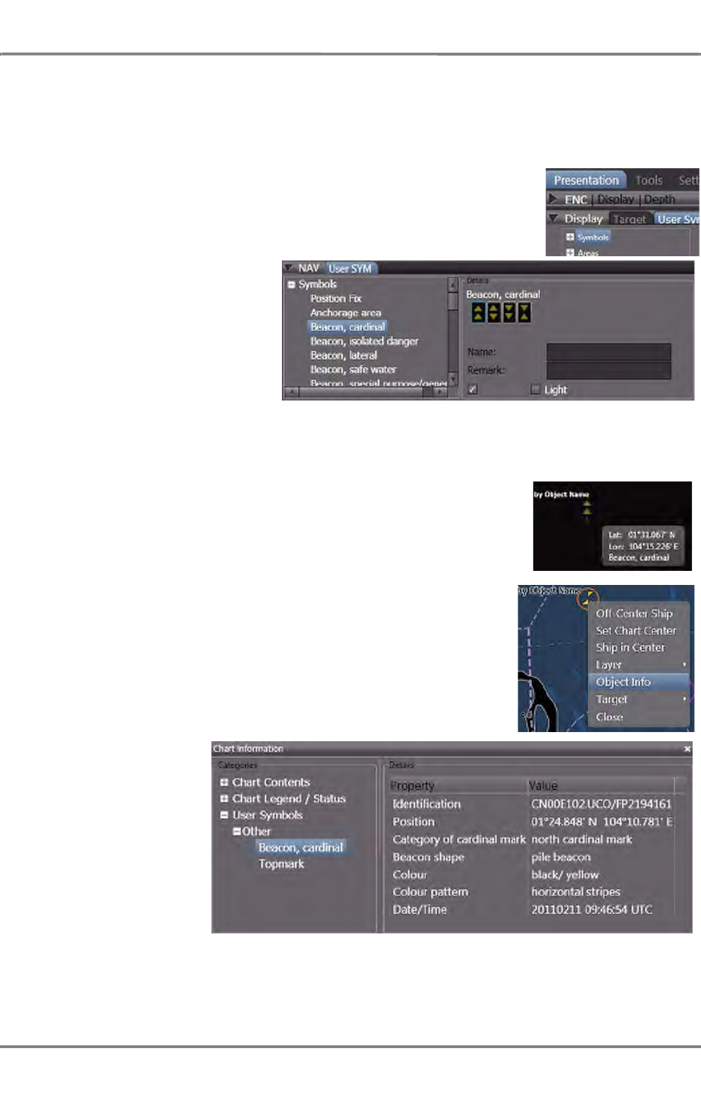
ED 3100 G 110 / 02 (2011-10)
Operating Instructions
A-8 User Symbols
A RADAR.fm / 10.11.11 A-85
NACOS Platinum
Placing a symbol - graphic mode
With this method, the user symbol can be placed in the chart/PPI area be means of the trackball/mouse.
The procedure is explained here by means of the user-symbol "beacon cardinal". It also works with all
other user symbols.
Open the User Symbols part of the Display expander and click on the
+
in
front of the desired category.
Symbols are so-called point objects which can have several different
attributes.
A list of the symbols in the selected
category will be shown.
Use the vertical scrollbar to see the
complete list.
Choose one symbol and select the
appropriate checkbox if the symbol
is to have a Topmark or an indica-
tion for a Light.
☞ Not every symbol can be set to have a topmark or a light.
A name for the object and additional information text can be entered in the text boxes.
Afterwards, click to highlight the desired symbol icon, move the pointer into
the chart area and click again to drop the symbol at the desired position.
The object will be shown with an object abbreviation in front of its name.
In the example, by means buoy. If the pointer is moved upon the object,
additional information is displayed.
Clicking the object with More will display the context menu. Clicking on
Object Info will open a new tab that displays detailed information
about the object which has been created by the operator.
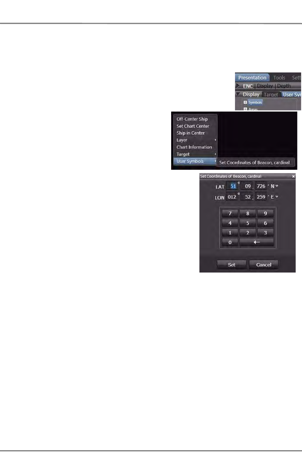
NACOS Platinum
ED 3100 G 110 / 02 (2011-10)
Operating Instructions
A-8 User Symbols
A RADAR.fm / 10.11.11
A-86
Placing a symbol - numeric mode
With this method, the user symbol can be placed in the PPI/chart area exactly at a desired position. The
procedure is explained here by means of the user-symbol "beacon cardinal". It also works with all other
user symbols
Open the User Symbols part of the Display expander and click on the
+
in
front of the desired category.
After selection and dropping of an object in the PPI/
chart area click More to open the context menu, in
the context menu, click on Set Coordinates and
enter the desired position in the pop-up window.
Click on Set to place the user symbol in the desired
position.
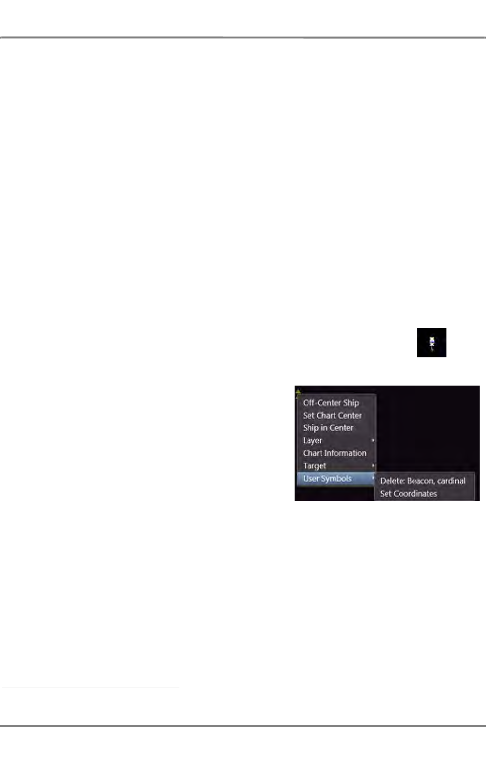
ED 3100 G 110 / 02 (2011-10)
Operating Instructions
A-8 User Symbols
A RADAR.fm / 10.11.11 A-87
NACOS Platinum
Modification of the Location of existing Symbosl - graphic mode
Each stored graphic element (a point symbol, a vertex of a line or area, a text note) has a geographic
position which can easily be changed at any time.
- Move the cursor to the symbol or vertex until the Hand cursor is shown,
- click on it to select the point,
- click and hold the Do key on the selected point
- and move the cursor to the wanted position.
- Release the Do key to fix and store the new position.
Modification of the Location of existing Symbols - numeric mode
- Move the cursor to the symbol or vertex until the Hand cursor is shown,
- click on it to select the point,
- click on it with More to open the context menu,
- in the context menu, click on Set Coordinates and enter the desired position of the user symbol
- Click on Set to place the user symbol in the desired position.
Removing a symbol
In order to remove a User Symbol from the chart and even from the data-
base, move the pointer above the symbol so that the pointer becomes a
small hand, then click on the symbol so that it is marked with a small
rectangle.
Then right-click the symbol in order to open the context-
menu and choose User Symbols and Delete <Symbol> 1)
1) <Symbol> is the designation of the symbol selected in the PPI/Chart Area
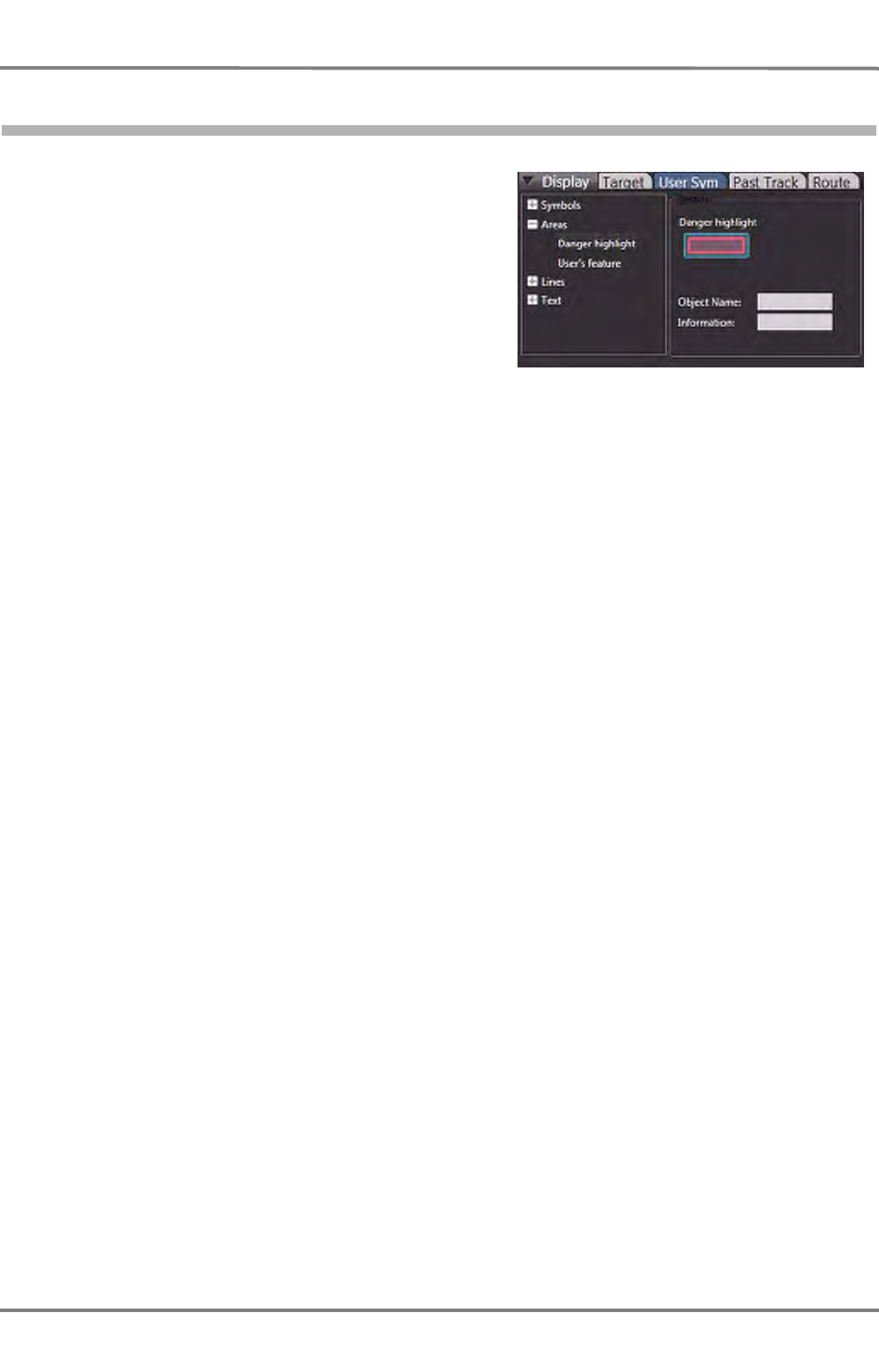
NACOS Platinum
ED 3100 G 110 / 02 (2011-10)
Operating Instructions
A-8 User Symbols
A RADAR.fm / 10.11.11
A-88
8.2 Areas
Editing of areas is following the same basic princi-
ples as shown above for Symbols (graphical point
objects).
In the selection list under Display, User Sym open
the list of available areas by a click on the (+)
symbol.
Select if you want to create a Danger highlight or
a User’s feature by a click on the entry in the
selection list.
Danger Highlight
A Danger Highlight is a red coloured filled area which can be monitored by the ECDIS’ chart monitoring
and the route monitoring functions.
Click on the Danger highlight icon first, and then click with DO in the PPI/Chart Area to set the first
vertex of the area. The moving cursor is then followed by a connection line to the previously set graphical
point of the area. In this way an area with 3 vertex points as a minimum can be set. There is no upper
limitation for the number of points which can be created for one and the same area.
To close the area after the last vertex is set,
- click into the last connection line with MORE or
- set the last point directly on the first one
to end the edit mode and to complete (close) the created area.
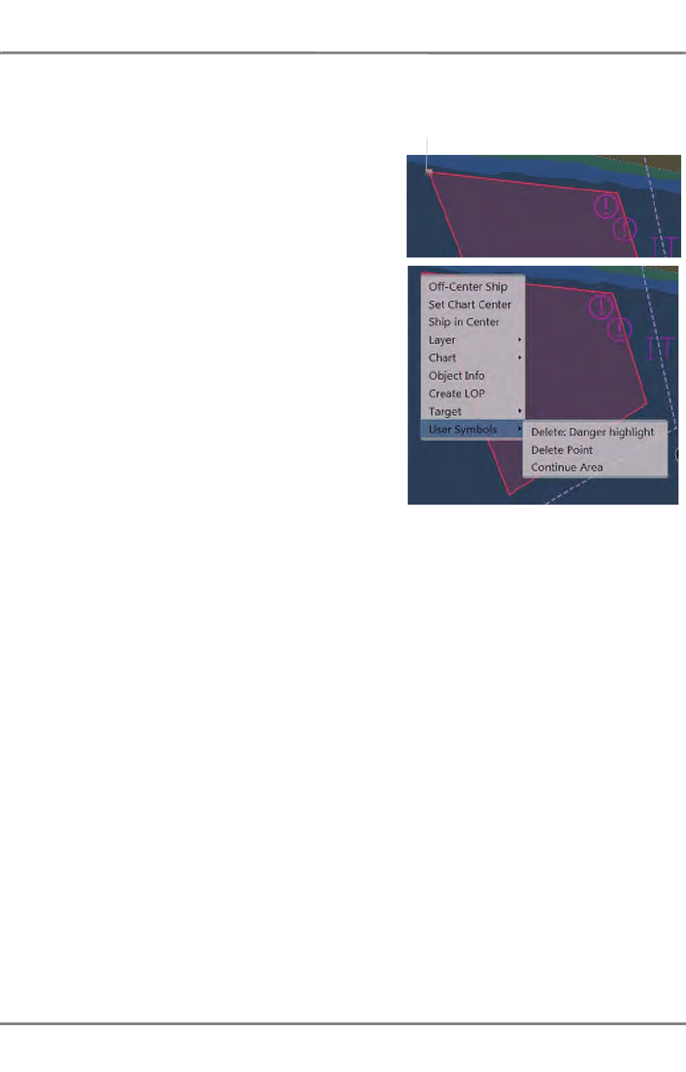
ED 3100 G 110 / 02 (2011-10)
Operating Instructions
A-8 User Symbols
A RADAR.fm / 10.11.11 A-89
NACOS Platinum
Removing an area
is done by graphical selection on the screen by a
click on one of the vertex points of an area. The
handle shown at the vertex indicates selection of this
area. A click with MORE on the handle or anywhere
in the selected area shows the context menu where
you must select Delete after a click on User Symbols.
You have the option to delete one point only to
change the shape (Delete Point) or to delete the
complete area (Delete: Danger Highlight).
Modification of an area is also done via the context
menu by selecting Continue Area. This creates a
new point or a sequence of new points until the
Modify mode is ended by a MORE click in the PPI/
Chart Area.
User’s Feature
Editing of Feature Areas is following the same prin-
ciples as shown above for Danger Highlights.
Several areas with different transparency (No Fill / 25 / 50 / 75 %) can be created and drawn on
the electronic chart. In contrast to the Danger Highlight a Feature Area cannot be monitored by the
ECDIS’ chart monitoring and route monitoring functions.
I.e. a Feature Area is only a display option without connected alert function.
Removing and modification of existing Feature Areas is done in the same way as for Danger Highlights
via the context menu (Delete: User’s Feature / Delete Point / Continue Area).
Handle
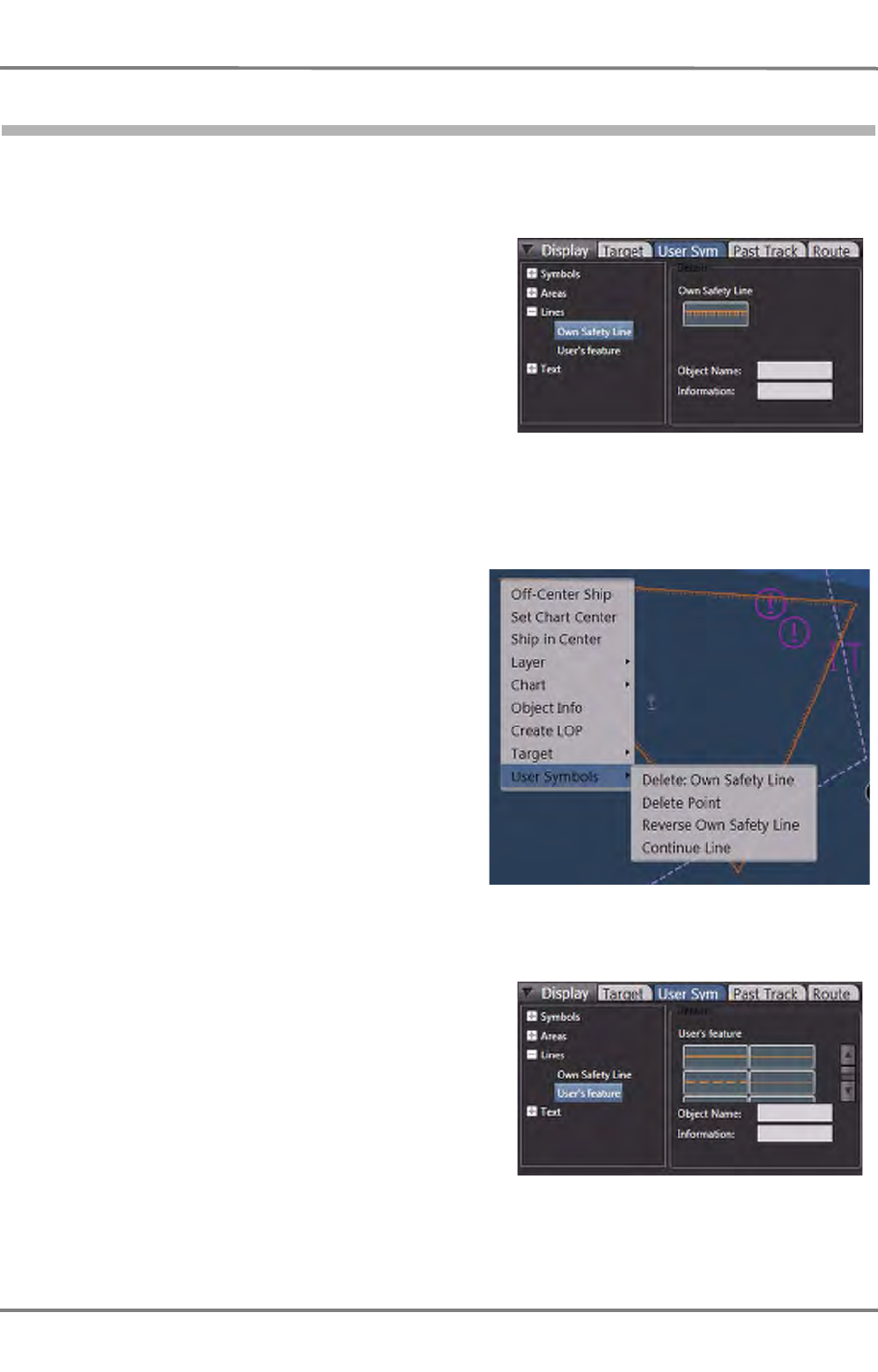
NACOS Platinum
ED 3100 G 110 / 02 (2011-10)
Operating Instructions
A-8 User Symbols
A RADAR.fm / 10.11.11
A-90
8.3 Lines
Editing of Lines is following the same principles as shown above for Danger Highlight areas.
In the selection list under Display, User Sym
open the list of available lines by a click on the (+)
symbol.
Select if you want to create an Own Safety Line,
a User’s Feature line or a Clearing Line by a click
on the entry in the selection list.
An Own Safety Line is a line with orange colour and with short hachure lines pointing to the dangerous
side. It can be monitored by the ECDIS’ chart monitoring and the route monitoring functions. You can
create several safety lines at different locations each having a variable number of vertex points, but a
defined start and a defined end.
Click on the Own Safety Line icon first, and then
click with DO in the PPI/Chart Area to set the first
vertex of the line. The moving cursor is then
followed by a connection line to the previously set
graphical point of the line. In this way a line with
2 vertex points as a minimum can be set. There is
no limitation for the number of points which can be
created.
To end the line after the last vertex is set, click
into the last connection line with MORE to end the
edit mode and to complete the created line.
The orientation of the own Safety Line (the
dangerous / not dangerous side) can be changed
by a click on Reverse Own Safety Line
User’s Feature Line
Several line styles with 4 different patterns (solid /
dashed / dotted / dashed-dotted) and 1 or 2 pixels
line width can be created and drawn on the elec-
tronic chart. In contrast to the Own Safety Line the
User’s Feature Line cannot be monitored by the
ECDIS’ chart monitoring and route monitoring func-
tions.
Removing and modification of existing Safety and
Feature Lines is done in the same way as shown
above for Areas via selection of the line on the
screen and subsequent operation via the context
menu by a MORE click on the selected line. You can choose to delete one single point or the complete
line.
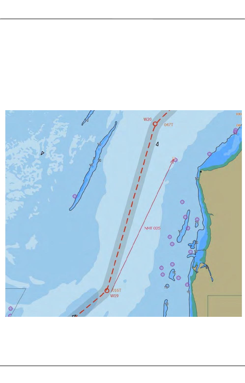
ED 3100 G 110 / 02 (2011-10)
Operating Instructions
A-8 User Symbols
A RADAR.fm / 10.11.11 A-91
NACOS Platinum
Clearing Line
CLearing lines (also called "Danger Bearing") shall indicate a limitation of the course to be steered in
certain sea areas. For this purpose a
- NMT Not More Than
and a
- NLT Not Less Than
line can be set. Select NMT or NLT and set the line as required. The course value not to be exceeded is
calculated automatically and is indicated together with the line and a direction arrow. The clearing lines
can only have two points (start and end point). To delete the line again, click on the start or end point
and then with MORE > User Symbols > Delete: Clearing Line the deletion can be executed.
Fig. A / 21 Planned track with Clearing Line (Not More Than 025°)

NACOS Platinum
ED 3100 G 110 / 02 (2011-10)
Operating Instructions
A-8 User Symbols
A RADAR.fm / 10.11.11
A-92
8.4 Events and Text
Editing of Events and Text Notes is another feature of the user object editor. You can drop Events which
have the symbol and add text to it. Additionally you can drop either a text object as Information
or as Caution . The procedure is identical for both objects.
The description for setting, modification and deletion is equivalent to the operation of point symbols, i.e.
you must select the relevant entry under User Sym, Events and Text, click on the respective icon, add
a text and then click into the PPI/chart area where the text note or the event marker shall be located.
After selection and marking by the orange handle you can move the event marker or text note to another
location or delete it from the screen and from the storage device.

ED 3100 G 110 / 02 (2011-10)
Operating Instructions
A-9 CHARTRADAR (optional)
A RADAR.fm / 10.11.11 A-93
NACOS Platinum
9 CHARTRADAR (optional)
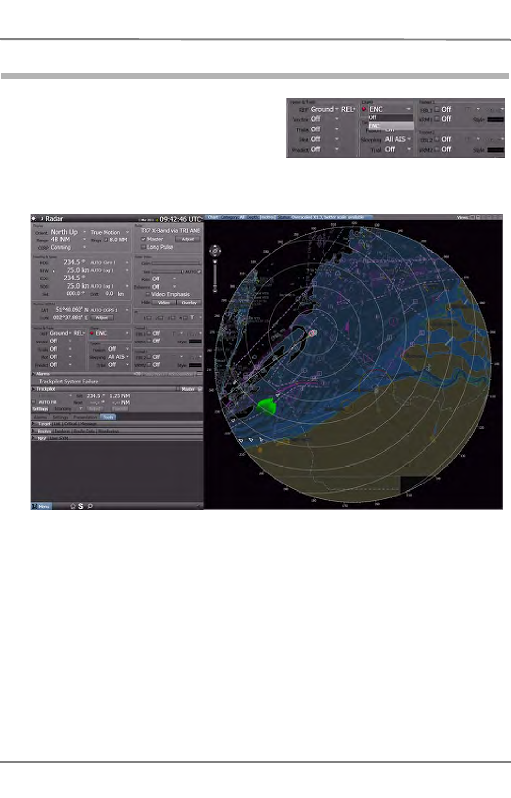
NACOS Platinum
ED 3100 G 110 / 02 (2011-10)
Operating Instructions
A-9 CHARTRADAR (optional)
A RADAR.fm / 10.11.11
A-94
9.1 Overview
The RADARPILOT Platinum can be upgraded with
the CHARTRADAR option. If this option is installed,
the drop-down menu in the Charts group of the
permanent area is selectable.
Select ENC in order to switch on the ECDIS chart in the background of the radar PPI. Select Off if you
want to switch off the chart presentation permanently.
Fig. A / 22 Overview of the CHARTRADAR screen
The above screenshot shows a typical scenario with the own vessel sailing through the English Channel,
course 235 deg at 25 kn. The operating of all the radar functions in the permanent area remains as it
used to be in RADAR Mode. Also the tabs in the non-permanent area remain as they used to be.
Under the tab Presentation the new tab ENC is displayed and can be opened with the Display menu
for setting of the chart objects (see chapter A - 9.3 on page A-97) and the Depth menu for setting of
the depth safety lines in the chart (see chapter A - 9.4 on page A-102). Under the tab Alarms the new
menu ECDIS Alerts is displayed and can beopened for activating i.e. safety contour alarm etc. (see
chapter A - 9.8 on page A-107).
If the CHARTRADAR option is installed, the SOLAS category of the radar system is extended with the
suffix C as follows:
With 22” TFT monitor: CAT 2 C
With 26” TFT monitor: CAT 1 C
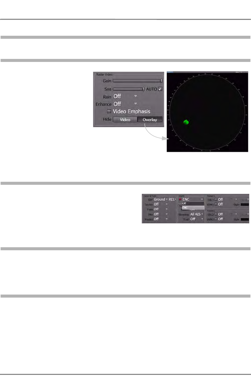
ED 3100 G 110 / 02 (2011-10)
Operating Instructions
A-9 CHARTRADAR (optional)
A RADAR.fm / 10.11.11 A-95
NACOS Platinum
9.2 Basic Adjustments
9.2.1 Temporary Hiding the Chart Background
If ENC is set and the chart
presentation shall be hidden
just for a few seconds in order
to identify details of the radar
image, just press Hide
Overlay in the RADAR Video
group.
The result is an empty screen
except for the radar video.
9.2.2 Selection of Charts
The drop-down menu in the Charts group of the
permanent area provides access to the different
charts that are installed on your CHARTRADAR
system. Only vector charts are permitted for a char-
tradar and only these are selectable. Raster charts
(RNC) can not be used.
9.2.3 Matching the Chart with the RADAR Presentation
If the chart underlay is not matching the radar PPI, the user may adjust the position data of the position
fixing device. This function is available from the permanent area in the Position WGS84 group. For
details please see chapter III - 3.2.3 on page III-42.
9.2.4 References Used
The CHARTRADAR uses the same reference system for own ship’s position, speed, heading, time, etc.
as the RADARPILOT. The common reference point is called Consistent Common Reference Point
(CCRP). It can be selected from the drop down menu CCRP in the Display group of the permanent
area (select Conning which is the default, or radar, or tracking). For details please see chapter III - 2.1
on page III-16 ff and see chapter III - 3.1.4 on page III-28.
For Route Monitoring against ECDIS objects and user objects the CHARTRADAR uses the track control
reference point which is typically at the bow of the vessel. This point is also called the system position.
The guard sector (also called look-ahead sector) starts from there. For details please see chapter III -
2.1 on page III-16.

NACOS Platinum
ED 3100 G 110 / 02 (2011-10)
Operating Instructions
A-9 CHARTRADAR (optional)
A RADAR.fm / 10.11.11
A-96
9.2.5 Range Scale and Modes
The CHARTRADAR provides the same range scale as the RADAR from 250 m to 96 nm. The larger scales
of an ECDIS with up to 800 nm are not available.
It provides also the same orientation as the RADAR with North Up, Head Up, and Course Up.
Further-on it provides also the same screen stabilisation as the RADAR with True and REL Motion. The
Browse mode which can be found in ECDIS for planning tasks is not available.

ED 3100 G 110 / 02 (2011-10)
Operating Instructions
A-9 CHARTRADAR (optional)
A RADAR.fm / 10.11.11 A-97
NACOS Platinum
9.3 Selecting the Objects to be Displayed in the Vector Chart
9.3.1 Overview
Symbols, areas, lines and labellings (collectively called objects in the following) are individually stored
electronically in a seperate data base and are displayed in the vector chart. Object classes (complete
sets of similar objects) are grouped into display groups; for example, the object class Restricted
Areas together with the object class Military Practice Areas and other similar object classes form the
display group Cautionary Areas. An appropriate and, at the same time, uncluttered display can be
achieved by selecting only those display groups which are required for the actual nautical task. Further-
more, for a number of objects (e.g. buoys), there is a choice between two symbol presentations. Irre-
spective of this, the number of text labels displayed can be influenced.
9.3.2 Categories of Display Groups
IMO has defined three categories for the selection of display groups that are to be shown:
- Display Base: Consists of the display groups which, as a minimum requirement, definitely have to
be displayed. They can not be influenced by the user and they are shown all the time. They are
normally not sufficient for safe navigation (only coast lines and obstacles).
- Display Standard: Contains the display groups which are normally necessary for voyage planning
and voyage monitoring (all standard display groups as shown below)
- Display All: Contains above two categories and all other display groups which are available in the
electronic chart
For the CHARTRADAR one further category is defined in the IEC 62388 test standard:
- Display Primary: The Primary Chart Information Set covers the display base plus fixed and
floating aids to navigation (buoys and beacons, details on following page).
SAM Electronics finally has added a category named Customized. In this category, all settings can be
made individually. See chapter A - 9.3.4 on page A-98 for details.
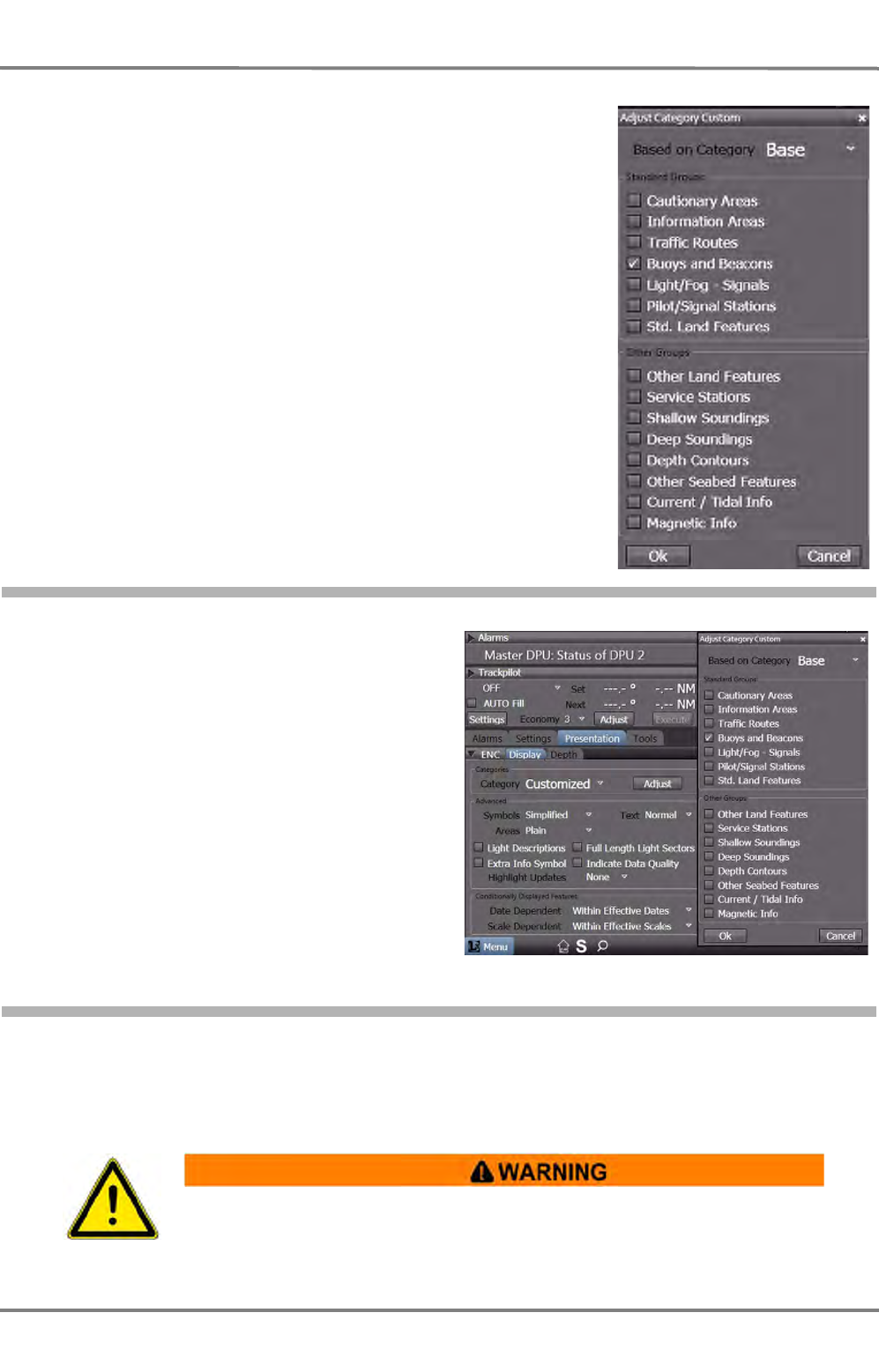
NACOS Platinum
ED 3100 G 110 / 02 (2011-10)
Operating Instructions
A-9 CHARTRADAR (optional)
A RADAR.fm / 10.11.11
A-98
The allocation of display groups into the three categories is basically
described in IMO Res. MSC.232 (82) which has replaced the older
recommendation A.817 (19) in the year 2008. Following this paper
the Base category in Platinum contains display groups as follows:
- coastlines (high water)
- own ship's safety contour
- isolated underwater dangers of depths less than safety contour
- isolated dangers within safe water (i.e. overhead wires)
Further-on scale, range and north arrow, units of depth and height,
and display mode are shown all the time.
The allocation for Standard and All in above resolution does not
reflect the real existing object classes in the S-52 standard. So for
the final definition of these groups the S-52 group names have been
used. The selection list is shown in the screenshot on the right.
9.3.3 Select a Category
For the selection of one of the display categories
open the tab:
Presentation->ENC->Display
and select the required category:
Base, Primary, Standard, All, or Customized.
If the latter is selected, the Adjust button is avail-
able and can be used to open the Adjust Cate-
gory Custom menu as shown in the right hand
screenshot. Now the display groups can be
adjusted individually.
9.3.4 Select the Primary Chart Information Set (PCIS)
The PCIS includes coastlines, own ship’s safety contour, and dangers to navigation as listed in IMO Res.
MSC.232(82) for the Base category plus fixed and floating aids to navigation (buoys and beacons). For
the display of this PCIS just select the Primary category.
When vector charts are being used, it must be ensured at regular intervals (e.g.
after a change of watch) that all of the necessary display groups are being
displayed. Not even the Display Standard setting guarantees the completeness of
the display.

ED 3100 G 110 / 02 (2011-10)
Operating Instructions
A-9 CHARTRADAR (optional)
A RADAR.fm / 10.11.11 A-99
NACOS Platinum
9.3.5 Indication of Category in the Status Line
The selected category (Base, Standard, All, Customized) is
indicated in the top status line of the application area.
A plus sign (‘+’) after the category is shown, if additional
groups have been selected.
A minus sign (‘-‘) after the category is shown, if additional
groups have been deselected.
Moving the cursor on top of the Category field opens a small
information window with details about the selected or dese-
lected groups.
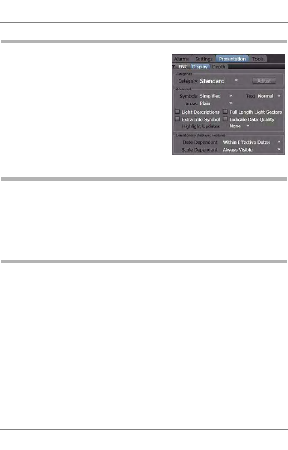
NACOS Platinum
ED 3100 G 110 / 02 (2011-10)
Operating Instructions
A-9 CHARTRADAR (optional)
A RADAR.fm / 10.11.11
A-100
9.3.6 Defining the Symbol Presentation
For symbols and areas, it is possible to define
whether they should be displayed in the same way
as on the paper charts or whether a simplified set of
symbols optimised for display on the screen should
be used. These settings are made in the menu Pres-
entation > ENC > Display.
9.3.7 Setting the Display of Text Labels
The number of text labels displayed can be specified by means of the Text dropdown menu:
- None: No text
- Few: Only the most important text labels are displayed.
- Normal: The text labels that are normally adequate for navigation appear.
- All: All text labels contained in the chart appear.
9.3.8 Switch on Additional Information
Check corresponding controls or select the appropriate dropdown-menus if required:
- Light Descriptions: Light descriptions are displayed
- Extra Info Symbol: Objects for which additional text information exists are marked.
- Full lenght light sectors: Light sectors are displayed true to scale
- Indicate Data Quality: Quality of chart data is indicated
- Highlight Updates: No, the last or all updates are highlighted, depending on the choice

ED 3100 G 110 / 02 (2011-10)
Operating Instructions
A-9 CHARTRADAR (optional)
A RADAR.fm / 10.11.11 A-101
NACOS Platinum
9.3.9 Switch on Conditionally Displayed Features
The conditions for Conditionally Displayed Features
can be set depending on different aspects:
- Date dependent: For objects which are not
present continuously, e.g. buoys which are
deployed seasonally, it is possible to define whether
the display is to take place only at the time entered
for it in the electronic chart. Select the corre-
sponding entry if needed.
• Within Effective Dates: Objects are displayed only during the time periods entered in the
electronic chart.
• Always Visible: Objects are displayed independently of the time periods entered.
- Scale dependent: For objects which are not present in all scales, it is possible to define in which
of the scales they are to be displayed. Select the corresponding entry if needed.
• Within Effective Scale: Objects are displayed only in the scale for which they have been
defined.
• Always Visible: Objects are displayed independently of the effective scale.
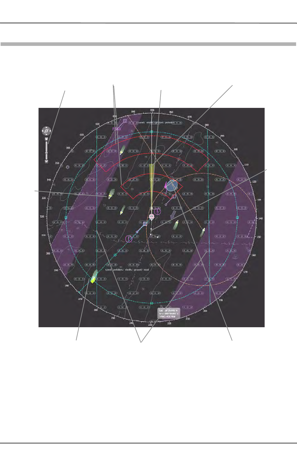
NACOS Platinum
ED 3100 G 110 / 02 (2011-10)
Operating Instructions
A-9 CHARTRADAR (optional)
A RADAR.fm / 10.11.11
A-102
9.4 CHARTRADAR Application Area
The screenshot below shows the CHARTRADAR in Head-up mode.
Fig. A / 23 CHARTRADAR Application Area with superimposed elements
EBL1/VRM1, centered Parallel index lines
Scale Slider
Plot
Heading line and
look-ahead sector
Vector
EBL2/VRM2, decentered
Acquisition/Guard
Zone 1 and 2
AIS/RADAR
target with
video
emphasis
and trail
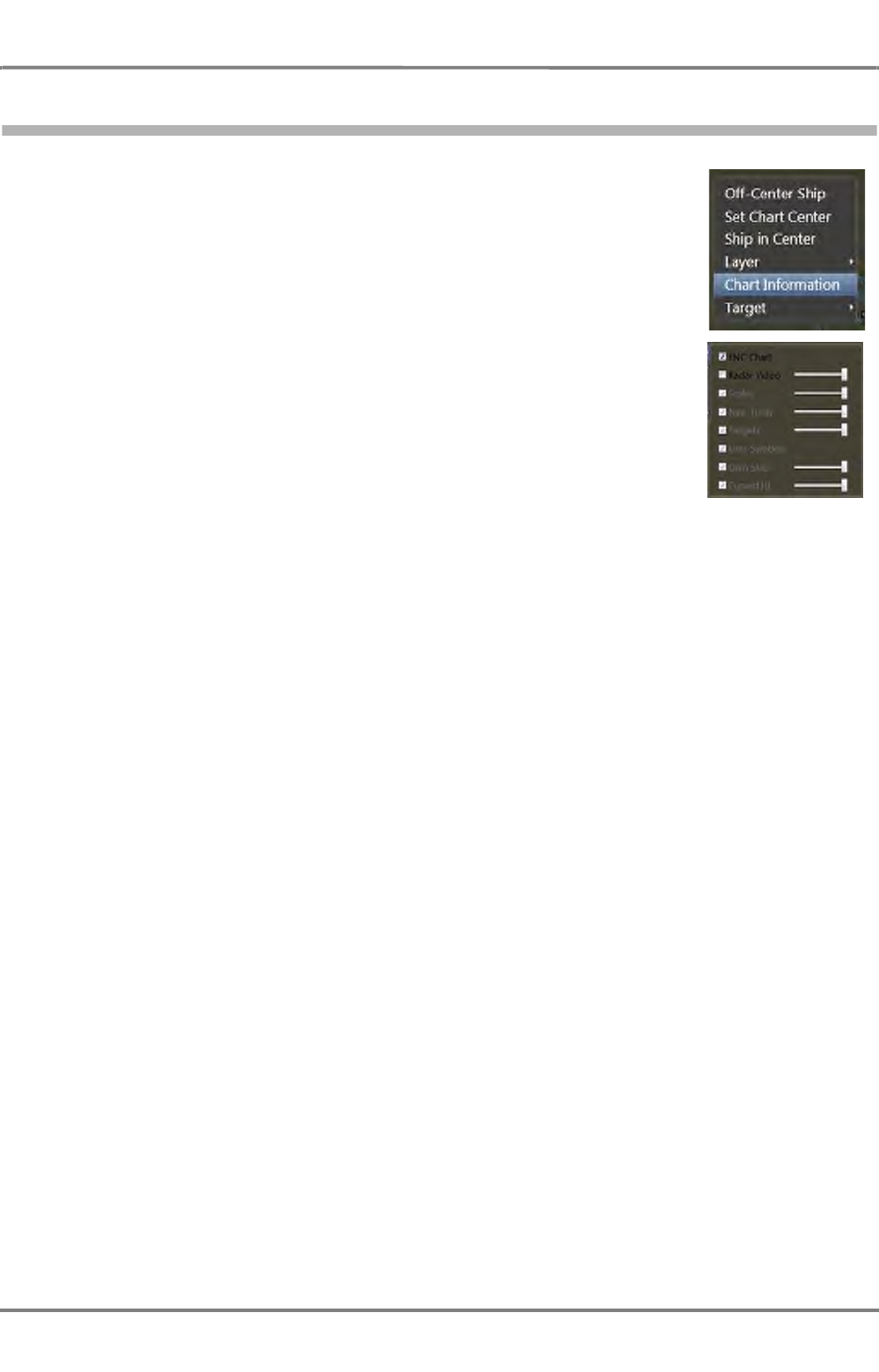
ED 3100 G 110 / 02 (2011-10)
Operating Instructions
A-9 CHARTRADAR (optional)
A RADAR.fm / 10.11.11 A-103
NACOS Platinum
9.5 Application Area Context Menu
A click with the More key in the application area opens the appropriate context
menu.
In difference to the context menu in RADAR, additional entries are present and
active.
- Set Chart Center. Right-Click a position in the PPI, in the opened
context-menu click Set Chart Center. The center of the display will then be
moved to the position that had been right-clicked before.
Exception: If the own-ship´s position would be moved out of the PPI or
even too far to the circular rim of the PPI, the center is only moved as far
as possible. See chapter A - 4.1 on page A-34 for details.
- Select Layer to set the brightness and visibility of the various layers
forming the complete display (see screenshot beside). For the CHAR-
TRADAR especially the brightness of the Chart information is important
and can be set.
- Chart Information. In this window, information about different criteria
of the chart database and the chart cells can be displayed. See chapter III
- 2.3 on page III-21 for details.
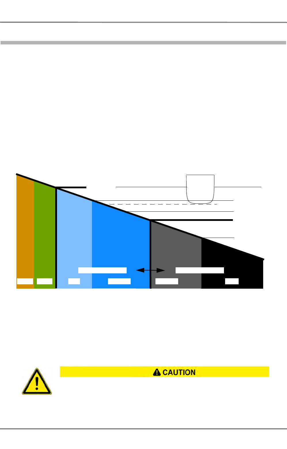
NACOS Platinum
ED 3100 G 110 / 02 (2011-10)
Operating Instructions
A-9 CHARTRADAR (optional)
A RADAR.fm / 10.11.11
A-104
9.6 Setting the Depths Lines to be Displayed in the Vector Chart
In the display of the vector charts, it is possible to use colour to clearly distinguish the navigable areas
from the non-navigable ones, depending on the draught of the ship. Navigable areas are displayed in
black or darkgrey, non-navigable areas darkblue or blue. The boundary between navigable and non-navi-
gable areas is the Safety Contour.
The Safety Contour is particularly important because it is also a basis for the ECDIS Monitoring and for
the checking of the pre-planned route.
It is also possible to distinguish between two areas with different depth ranges, inside the navigable area
as well as inside the non-navigable area :
- Within the navigable area, the Deep Contour differentiates between the adequately deep areas
displayed in darkgrey and the deeper areas displayed in black.
- Within the non-navigable area, the Shallow Contour differentiates between the areas displayed in
darkblue which are adjacent to the navigable area, and the even shallower areas displayed in blue.
Fig. A / 24 Diagram of the depth contour system
Spot soundings from individual measurements are displayed more prominently if they project beyond a
particular depth. This depth is set as the Safety Depth. This situation is shown graphically in the figure
above.
The respective colour settings for the Shallow and Deep Contour as well as the Safety Depth and
the Safety Contour are adjusted on the Depth panel of the ENC expander:
Wrong or inadequate setting of especially the Safety-Depth and/or Safety Contour can give
a wrong impression of navigable/non-navigable areas displayed on your chart. Both values
shall be selected with sufficient safety depending on the draft of your ship.
Chart zero
Shallow contour
Safety contour
Deep contour
Safety depth
Draft
Brown Green Blue Darkblue Darkgrey Black
Non-navigable area Navigable area
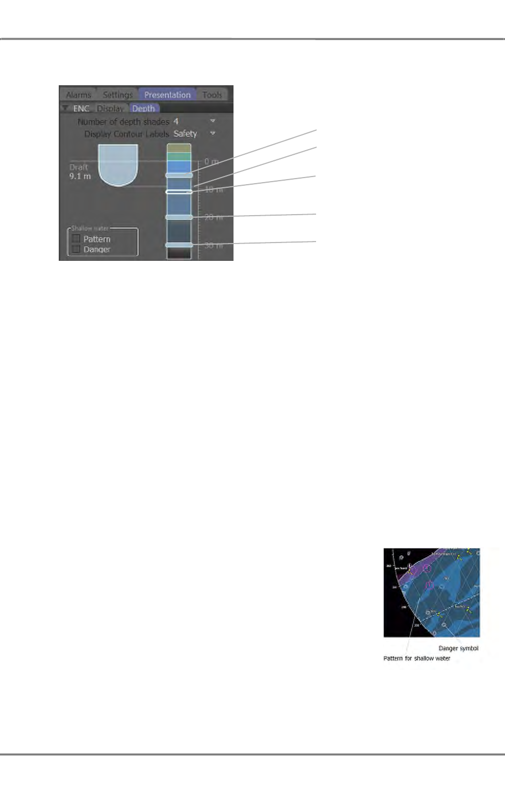
ED 3100 G 110 / 02 (2011-10)
Operating Instructions
A-9 CHARTRADAR (optional)
A RADAR.fm / 10.11.11 A-105
NACOS Platinum
Fig. A / 25 The Depth Panel
On the electronic chart the colours indicate the depth as adjusted in the dialogue, from brown (land) to
blue (shallow), grey (navigable) and black (deep).
Note:
The colours defined in this chapter are based on the ECDIS colour schemes "Dusk" and "Night" so that
the radar video and the target graphics are not obscured. After a restart of the system all depth contour
values are set in the same way they have been set before.
Shallow Water settings
Non-navigable areas of vector charts can be marked by means of a pattern, particular dangers within
non-navigable areas can be accentuated.
Pattern
Non-navigable areas (shallow water) can be displayed crisscrossed if
this option is checked.
Danger
The display of the isolated danger symbols which are situated in shallow
water can be switched on and off here. Those symbols are only
displayed if the display category is set to Standard at least.
The four different depth settings can be
adjusted by dragging the horizontal
sliders on the vertical bar.
Shallow contour
The Set Draft of own vessel is shown as
a dashed horizontal line.
Set the safety depth (transparent glider,
triggers the alert) to Set Draft plus
reserve of about 2m.
Safety Contour (value greater than
safety depth).
Deep Contour.
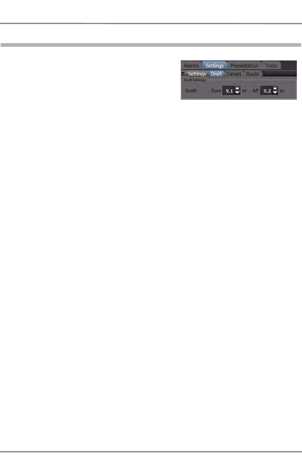
NACOS Platinum
ED 3100 G 110 / 02 (2011-10)
Operating Instructions
A-9 CHARTRADAR (optional)
A RADAR.fm / 10.11.11
A-106
9.7 Setting the Own Ship’s Draft
Open the own ship’s draft menu in the tab:
-> Settings -> Draft and set Fore and Aft draft of
your vessel. The larger of the two values will be
displayed in the menu for setting the depth lines.
The set own ship’s draft will only limit the adjustment
of the safety contour in the depth line menu to the
lower side. The safety contour slider can only be set to
larger values. The ENC depth monitoring alarm is not
affected by the own ship’s depth, it is only affected by
the set safety contour.
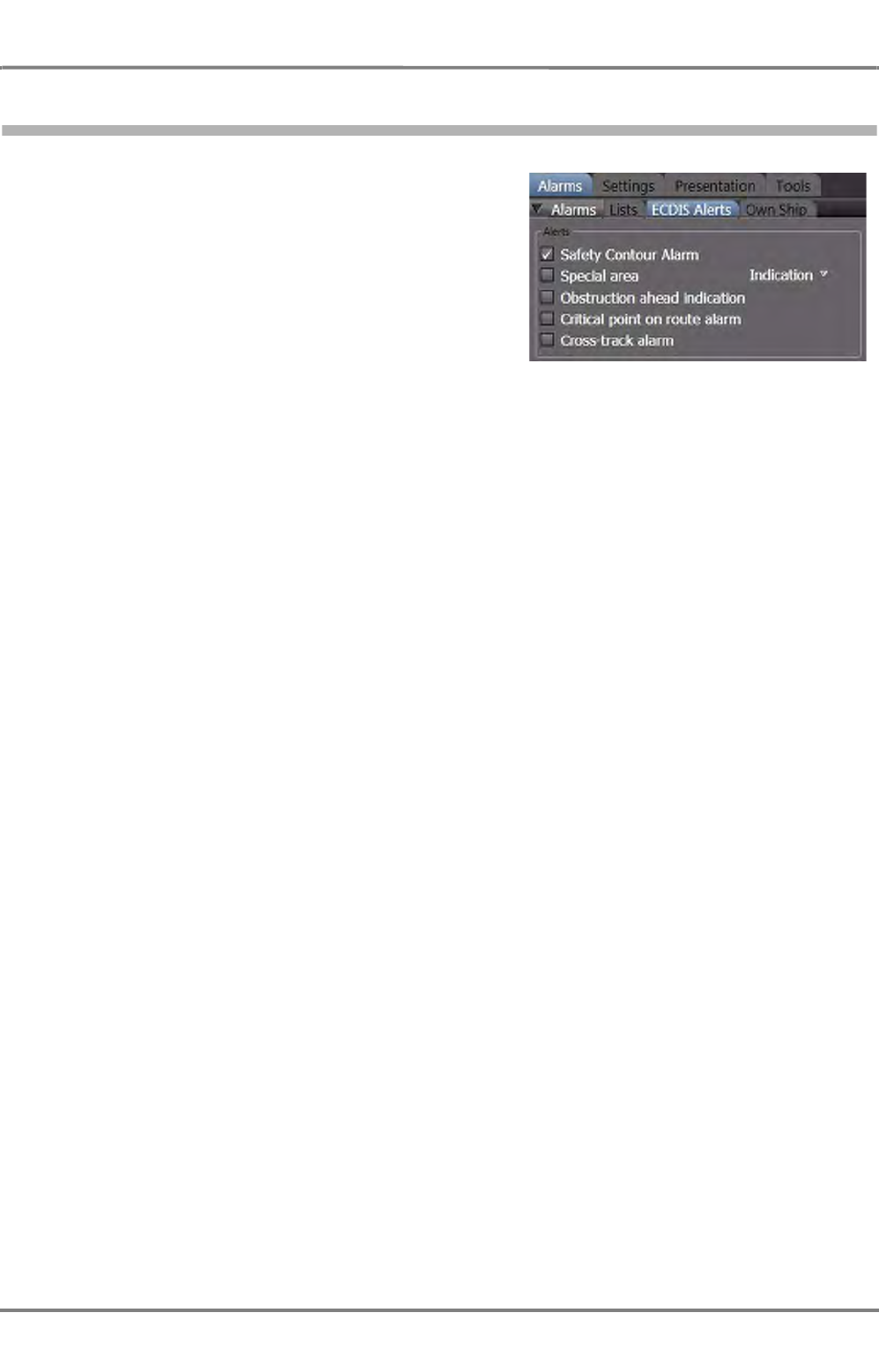
ED 3100 G 110 / 02 (2011-10)
Operating Instructions
A-9 CHARTRADAR (optional)
A RADAR.fm / 10.11.11 A-107
NACOS Platinum
9.8 Activating the Chart Monitoring
Open the ECDIS Alerts menu in the tab:
-> Alarms -> ECDIS Alerts
and check the required controls. At least the safety
contour alarm should be set if an alarm shall be raised
as soon as the vessel is sailing into shallow water.
Further alarms or warnings can be set for approaching
special areas, obstructions, wrecks, rocks etc. For details
see chapter C - 2.2 on page C-38.
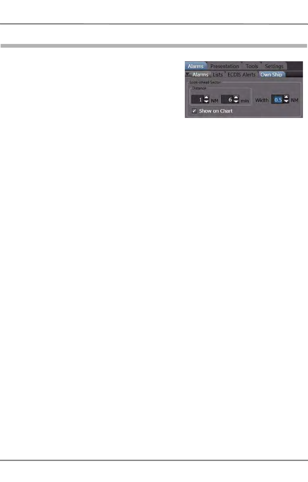
NACOS Platinum
ED 3100 G 110 / 02 (2011-10)
Operating Instructions
A-9 CHARTRADAR (optional)
A RADAR.fm / 10.11.11
A-108
9.9 Setting the Look-Ahead Sector
If one or more ECDIS alerts are set as described before,
the chart monitoring is performed with the own ship’s
contour as a guard sector. This guard sector is extended
by a look-ahead sector thus achieving an appropriate
pre-warning time.
Open the Own Ship tab in the Alarms expander and
set the Distance in terms of nautical miles (NM) as well
as time (min) of the look-ahead sector (the first condi-
tion which applies, travel distance or time to dangerous
object, will activate the alert). These two parameters for
the distance (NM and min) will cover the speed of own
ship as well as the following example shows:
Own ship is sailing 15 kn per hour.
The time is set to 6 min as shown in the screenshot above.
The alarm would be activated at a distance of 6 min/ 60 min * 15 kn =1.5 NM
So this speed dependent alarm would already be raised at a distance of 1.5 NM and not at 1 NM as set
as a minimum.
Define the Width of the look-ahead sector as well. Check the Show on Chart control if the look-ahead
sector shall be visible in front of the own ship symbol or contour. The minimum settings are 0.5 NM, 1
min, and 10 m width meaning that the look-ahead sector is active at any time with a minimum size.
Suppressing of alerts is only possible from the above ECDIS Alerts menu.
Once set, the appropriate ECDIS Alerts are raised every time the look-ahead sector touches a safety
contour or obstacle. This chart monitoring process is independent wether the look-ahead sector is visible
or not and even independent wether the chart visualization is switched on or not.
But of course the optional CHARTRADAR function with the corresponding ENC charts for the actual
passage is required. For more details about the look-ahead sector see chapter C - 2.2 on page C-38.
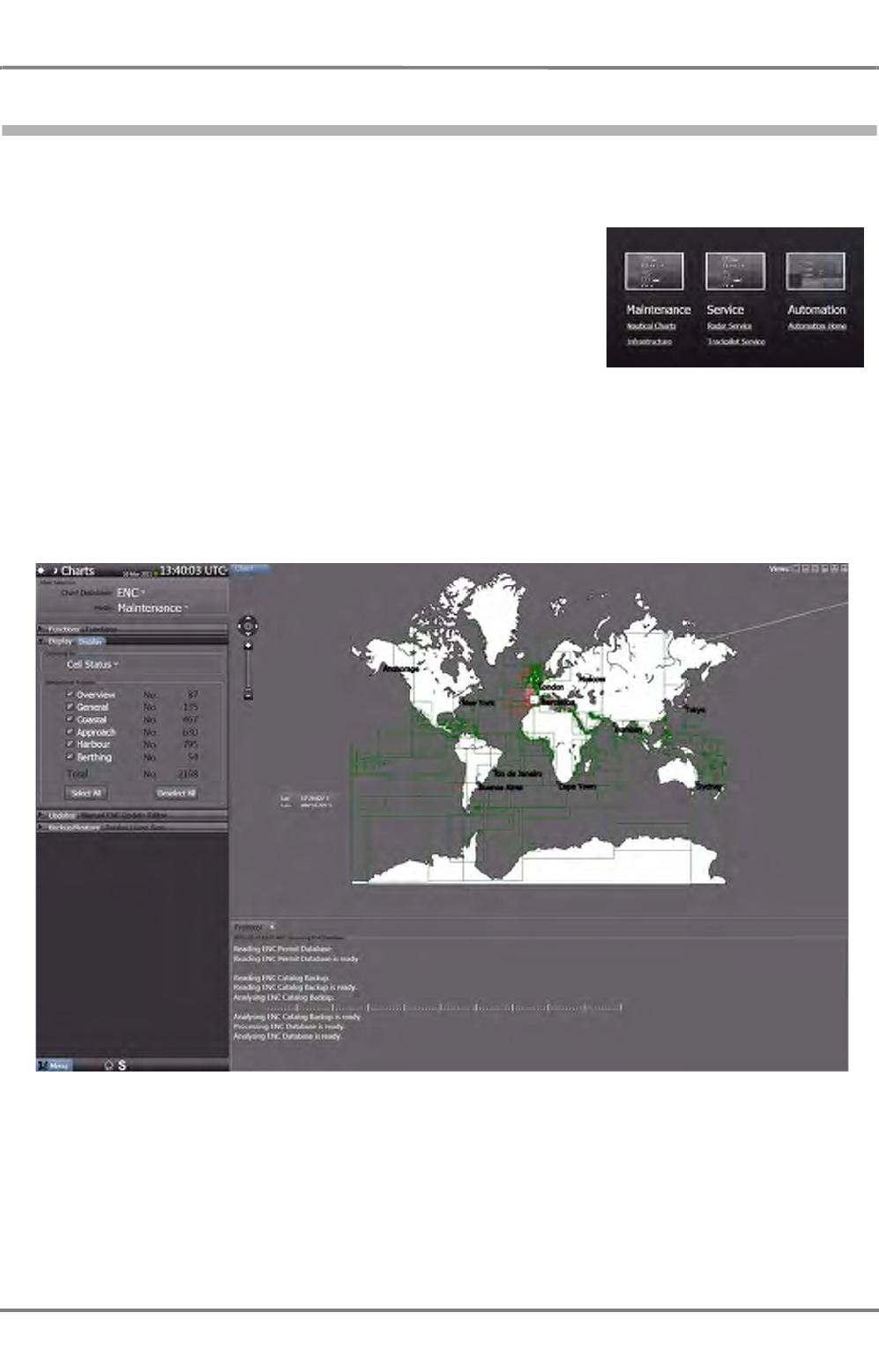
ED 3100 G 110 / 02 (2011-10)
Operating Instructions
A-9 CHARTRADAR (optional)
A RADAR.fm / 10.11.11 A-109
NACOS Platinum
9.10 Chart Maintenance
For the maintenance of charts the separate application Chart Maintenance is accessable from the
Super Home page.
First leave the CHARTRADAR or RADAR application by selecting
the Super Home page. From here open the Maintenance ->
Nautical Charts application. Follow the instructions given in the
chapter
H-Data Maintenance of the Electronic Charts
.
Each new chart or update of an existing chart is completely
checked during the loading process for corrupted data. If the data
structure is not matching, the process is stopped, if single data for
a cell are out of value range, a message is given and the operator
can decide how to proceed. Finally the chart data are stored in an internal machine code on the
CHARTRADAR. As this code has been thorougly checked during loading, it can not cause any interruption
or breakdown during the use of the CHARTRADAR.
☞ As long as the loading process with new chart data is running the system must not be used for
navigation purposes.
Fig. A / 26 Overview of the Chart Maintenance Screen
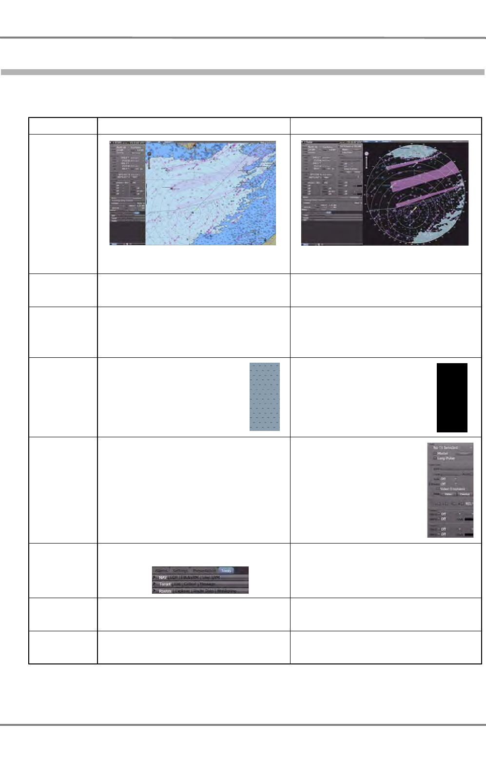
NACOS Platinum
ED 3100 G 110 / 02 (2011-10)
Operating Instructions
A-9 CHARTRADAR (optional)
A RADAR.fm / 10.11.11
A-110
9.11 Main Differences between CHARTRADAR and Full ECDISPILOT
The ECDIS application, which is used for the CHARTRADAR is a subset of the software package used for
the full ECDIS. The main differences can be summarized as follows:
Table A / 14 Differences between CHARTRADAR and ECDISPILOT
Function ECDISPILOT CHARTRADAR
Overview
(the two
screenshots
show exactly
the same posi-
tion of own
vessel and the
same bright-
ness settings)
The chart is presented in a full rectangle The chart is presented in the radar PPI
Planning With the Browse function any position in the
worldwide chart can be shown in the centre No Browse function selectable, the own ship
remains always visible within the PPI, no
planning
Presentation
of radar video
and chart
The ECDIS colour set according to IHO S-52
presentation library appendix 2 is used with
colour sets for day, dusk, and night. The radar
video is in the background and superseded by
any ECDIS symbols
The radar video is always in the foreground,
the ECDIS is presented as an underlay
providing a dark background for radar video
(colours are closely aligned to ECDIS dusk
and night colour tables)
Presentation
of no-chart
data areas
Operating of
radar No operating of radar TX functions possible,
corresponding side bar in permanent area is
suppressed
Operating of
navigation
tools
LOP, EBL, &VRM and PI lines are available
from ->Tools ->NAV tab EBL, VRM and PI lines are available from the
radar function side bar in the permanent area,
LOPs are not available
Display object
groups Can be displayed per category: Base,
Standard, All and Customized. The last one
provides individual selection of groups.
Same as ECDIS plus Primary category; Select
Primary to set the Primary Chart Info Set (IEC
62388)
Display ECDIS
Symbol Library
Chart1
ECDIS Chart1 is a tab that can be opened in
the application area, shows a legend of
symbols used
No comparable function available, the symbol
legend would cover the radar presentation,
not permitted
An area with no-chart data
of any kind is marked with
the “no data” symbology
defined in the IHO S-52
presentation library
appendix 2/3.2.3(14)
According to IEC 62388
Ch. 11.1.8.2 the no-data
area is shown as the
radar background, here in
black
Operating of radar TX func-
tions possible, corresponding
side bar is available

ED 3100 G 110 / 02 (2011-10)
Operating Instructions
A-9 CHARTRADAR (optional)
A RADAR.fm / 10.11.11 A-111
NACOS Platinum

NACOS Platinum
ED 3100 G 110 / 02 (2011-10)
Operating Instructions
A-9 CHARTRADAR (optional)
A RADAR.fm / 10.11.11
A-112

VOYAGE PLANNING AND
MONITORING

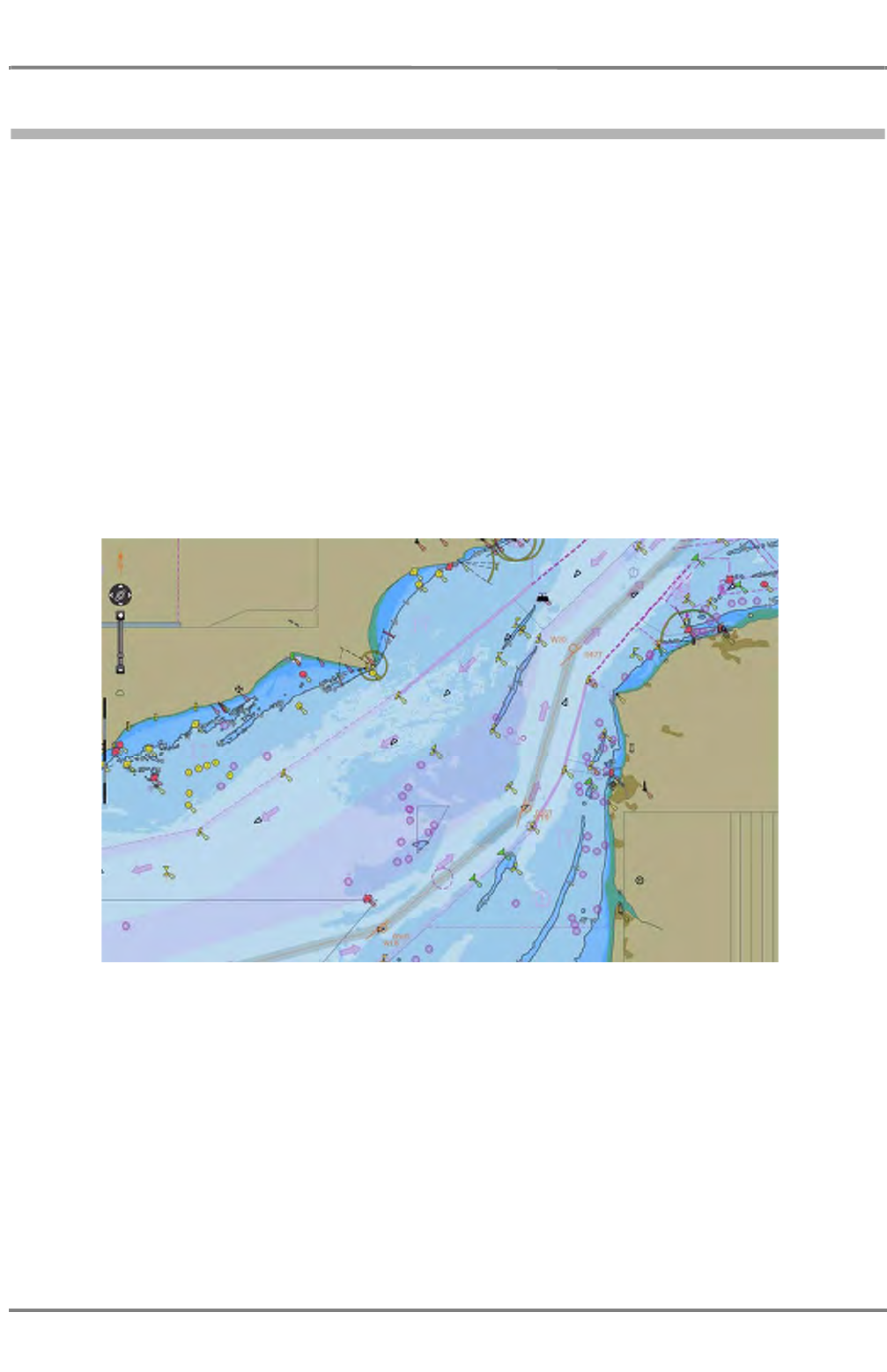
ED 3100 G 140 / 04 (2011-11)
Operating Instructions
C-1 Voyage Planning
C VOYAGE PLANNING & MONITORING.fm C-3
NACOS Platinum
1 Voyage Planning
Voyage planning and voyage monitoring (see chapter 2 on page C-35) are common functions for the
integrated system.
The part of the (long-term and medium-term) voyage planning that can be performed on the system
consists of
- generating and, if necessary, modifying the pre-planned route. See chapter 2 on page C-35
- procuring and updating the electronic chart for the voyage area. See chapter 1 on page H-3 for
details.
- if necessary, generating User Symbols, i.e. additional user made symbols, lines and areas to be
displayed on the chart area and to be used for monitoring purposes.
- performing the check and verification of the planned route against the electronic chart and/or
against the user made chart objects.
- and -optionally- establishing a speed and time schedule by input of speed limitations, the time of
departure and time of arrival, or by setting the of a planned speed for the entire route.
Fig. C / 1 Planned Route
Any route established during voyage planning can be activated as System Route for use on all
MFDs configured for navigation. During voyage execution the route can be monitored automatically
and can be used for automatic steering if a track control system (TRACKPILOT) is part of the system
configuration.

NACOS Platinum
ED 3100 G 140 / 04 (2011-11)
Operating Instructions
C-1 Voyage Planning
C VOYAGE PLANNING & MONITORING.fm
C-4
1.1 Generation of Routes
The work on the pre-planned tracks by the so called Route Editor can be performed on any Multi Func-
tion Display in RADAR or in ECDIS mode, whichever is selected. These items of equipment will exchange
the entered data with one another, so that (for example) a route that is generated on the ECDISPILOT
can also be altered on any RADARPILOT. The same is valid for the RADAR and ECDIS modes on a MFD.
☞ It is generally recommended to perform route editing on the ECDISPILOT or in ECDIS mode, where
the established route is displayed on the electronic chart. In many installations the workstation for
planning is equipped with an alphanumeric keyboard which supports easy input of the numerous
numeric and textual data required for route editing.

ED 3100 G 140 / 04 (2011-11)
Operating Instructions
C-1 Voyage Planning
C VOYAGE PLANNING & MONITORING.fm C-5
NACOS Platinum
1.1.1 General Information about Pre-planned Tracks
Pre-planned tracks 1) are routes which are generated on the basis of waypoint sequences for a planned
voyage and which are stored 2) in the form of files sorted in folders containing route catalogs.
Routes can be used by the components of the system as follows:
- Routes can be displayed in the chart area on the ECDISPILOT and in ECDIS mode on a MULTIPILOT.
In the planning mode the screen can be centered on any part of the route (Browse Mode)
- On any RADARPILOT and in RADAR mode on a MULTIPILOT, one or more routes can be selected
and overlaid to the radar picture. The presently visible part of the pre-planned track is then
displayed automatically on the PPI area.
- One of the displayed routes can be defined as the System Route, which is then effective for the
entire system. With the aid of the TRACKPILOT, the ship can be piloted automatically along the pre-
planned track contained in the route dataset. But even during manual control of course and speed,
the diverse displays at the system components that refer to the System Route can be most helpful.
- If the Planned Track Speed is input at the beginning of the voyage, the system calculates a time
schedule based on the speed settings contained in the planned route. Its purpose is to calculate the
resulting estimated time of arrival. The estimated time elapsed (ETE) will also be displayed together
with the planned speed value.
- If the planned time of arrival (ETA) is input at the beginning of the voyage, the system contin-
uously performs a speed calculation while the ship is sailing along the route; this calculation is based
on the Departure and Arrival Time set for the planned route, and its purpose is to achieve the
required time of arrival at the end of the route by an appropriate speed setting.
- In both cases, the result, the Calculated Speed, is displayed in the Route List, and can be used
by the operator as the current speed setting during manual speed control. The calculated speed
values are in any case limited to the MAX SPD values defined for each leg of the route.
- In systems with integrated CONNING display (CONNING mode or CONNINGPILOT), the special
Active System Route display can be used to monitor the time schedule along the route and for
the selected Arrival Point.
- If the system is equipped with a SPEEDPILOT, the speed can also be controlled automatically while
the ship is sailing along the System Route, in such a way that the calculated speed is achieved and
the time schedule planning is thus fulfilled.
Geographical Position and Shape of a Route
A route is divided by waypoints into segments which are commonly named legs or track segments.
The waypoints are the main construction elements of the route. Their positions are defined by geograph-
ical coordinates in the WGS84 system. See chapter C - 1.1.2 on page C-7 for details.
If it is planned that the ship will change course at a waypoint, the radius of the turn must be specified.
In this case, at the beginning of the manoeuvre computed on the basis of the specified radius, the track
curve leaves the track line 3) at the wheel over point (WOP), and after completion of the manoeuvre
it goes over to the next track line. The track curves shown are calculated based on the manoeuvring
parameters defined for your ship on service level during the sea trials.
The geographical coordinates of the waypoints, together with the radii assigned to the waypoints, thus
define the geographical position and shape of the pre-planned track including the track curves at the
waypoints.
1) In this document, pre-planned tracks are also simply called routes if there is no danger of confusion.
2) Any change of the route data, made on any MFD, is saved on all MFDs automatically.
3) Track line is a line joining two consecutive waypoints, also called leg in this operating instructions

NACOS Platinum
ED 3100 G 140 / 04 (2011-11)
Operating Instructions
C-1 Voyage Planning
C VOYAGE PLANNING & MONITORING.fm
C-6
Routes each have a first waypoint and a last one. During editing, all waypoints are automatically
numbered consecutively, beginning at 1 for the first waypoint. All route functions refer to this sequence.
Thus, a route can only be sailed in the direction for which it has been generated.
However, the direction of a route that has already been generated can be reversed by means of a simple
operating step during editing and then processed further - see figure below.
Fig. C / 2 Shape of the pre-planned track in the case of course changes
There is practically no limit to the number of waypoints that a route can consist of, or to the length of
a route. Thus, the entire route between two ports can be defined as one pre-planned track. It can often
be appropriate to divide the entire distance up into individual routes.
For example, if a port is approached from various directions along various routes, it might be appropriate
to perform separation into the port-related segment that is identical for all routes and the part that is
specific for the route concerned. In this way, the data relating to the port need to be input once only,
and the maintenance of these data only has to take place in one dataset.
Last
waypoint
(From WPT)
Actual waypoint
(To WPT)
Radius
Track
line
WOP
Sailing direction
Next
waypoint
Track
curve

ED 3100 G 140 / 04 (2011-11)
Operating Instructions
C-1 Voyage Planning
C VOYAGE PLANNING & MONITORING.fm C-7
NACOS Platinum
1.1.2 Generation, Handling and Administration of the Routes
During the generation of the pre-planned tracks, you can transfer the waypoint positions graphically,
(in Graphic mode) from the electronic chart displayed on the chart area.
You can also edit the waypoint positions by alphanumeric input (in Text mode); all other data, like
- administrative data,
- notes to the waypoints,
- additional route parameters, and
- parameters for the track and speed control functions
must be edited in text mode anyway.
Editing in Text mode means data input in the Waypoint List and the Route List displayed as two
linked tables shown in the lower part of the application area.
In Text mode, the following functions too are possible:
- During the generation of a route, waypoints - including all data assigned to a waypoint - can be
taken over (copied with Copy and Paste) from routes that already exist.
-By means of the Reverse function, the direction of the route can be reversed, i.e. the first waypoint
becomes the last one, and so on.
At any time you can change between graphical editing and text mode as long as the PPI/Chart area
shows the relevant part of the pre-planned track being edited.
Once the route has been generated, it should definitely be checked with the special checking function
available in the header of the Waypoint List.
The route that is checked must be stored in the form of a separate file 1) on the hard disk of the MFD
and assigned to a catalog. During the editing process, you have to give the route a route name, by
means of which the system - in conjunction with the catalog name - can clearly identify any route. So
that you too can identify the parts of the route later, you should also give some important waypoints an
appropriate waypoint name before you start the storing process.
If a route is to be displayed or modified on the system, you first have to load it. In this process, a route
stored on the hard disk is copied into the main memory of the MFD. Each time you load or reload a
route the results of the route check get lost, i.e. the check route function must be executed once more.
For modifying a route, you have all of the input possibilities that are also available to you for the initial
generation process. After the modification, the route must be stored again. If this is done under the old
route name, the old data set of the modified route is lost. If, during the storing process, you input a
new route name, the modified route is stored additionally as a new route; in this case the original
route continues to exist in unchanged form.
Although it is improbable, hard disk drives can get damaged or the data stored on them can be erased
or be unreadable. So that, in such cases, the stored data are not irretrievably lost, it is absolutely essen-
tial to make a backup copy 2) at regular intervals, i.e. before such an event can occur. After a hard disk
fault or after the hard disk has been exchanged, the files can then be copied back2) to the hard disk
drive. This mechanism can also be used to exchange files between the systems on different
ships.
If your system includes more than one MFD with navigation functionality, all routes generated on one
MFD are also copied automatically to all other MFDs.
1) In the following, no distinction is drawn between the route and the route file.
2) On/from a removable device

NACOS Platinum
ED 3100 G 140 / 04 (2011-11)
Operating Instructions
C-1 Voyage Planning
C VOYAGE PLANNING & MONITORING.fm
C-8
USEFUL INFORMATION
Browse Mode on ECDIS
If you want to edit the route graphically on the electronic chart, it is advisable to switch into the Browse
mode 1) in order to be able to show any part of the sea where the route shall be located. In the other
display modes you are only able to plan a route with about 96 nautical miles distance to your own actual
position.
Alternatively all inputs for route planning can also be made in Text mode, i.e. directly by alphanumeric
inputs into the columns of the waypoint list (See chapter C - 1.1.3 on page C-9 for details).
General Note about Editing in the Waypoint List and the Route List
It is generally recommended to connect an alphanumerical keyboard (also called ASCII keyboard) to the
MFD computer installed at the planning workstation or any MFD frequently used for editing and chart
maintenance purposes.
In this case the system supports such well-known functions like copy and paste within the route editor;
Copy by Crtl+C and Paste by Ctrl+V. This can be applied on a whole line as well as on a data cell of
a table or parts of it.
Coordinate System for Position Input (WGS84)
The position data that are input on the system have to refer to a particular coordinate system. It is not
possible to choose between various coordinate systems or different geodetic datum.
Generally, the ECDIS programs (and also all connected RADAR / NACOS components) work internally
with the chart datum WGS 84. Before position data referring to a different chart datum are input on the
system, a conversion to WGS 84 must take place before input 2).
A necessary prerequisite for correct conversion is that the chart datum used on the source of the position
data (a paper chart, a waypoint list, etc.) is known to the operator!
Name of the Waypoint
At the left end of the header of the route window under “Find” you can enter any search text which is
contained in the waypoint names. This search text is compared to the start of the text entries contained
in the Name fields of the waypoints. With this function it is possible to have a fast access to the location
of a known waypoint (with given name) in long lists. If you then double click on the found waypoint line
or if you use the Go to Waypoint function, the chart center will jump to that position.
1) Browse mode is only available in ECDIS mode, i.e. in RADAR mode graphical route planning is limited to the
display range selected for the PPI.
2) The World Geodetic System 1984 is the actually used geodetic reference system for positioning. It is used world-
wide as a common base for position data, specifically in the GPS satellite system and in GPS receivers.
Also the position sensors connected to the system must send out their data based on the WGS 84 position datum.
A position receiver not sending WGS 84 based data to the NACOS is automatically treated as invalid and the alarm
"No WGS84 Position Datum in Use" will be given if you select it as position input.
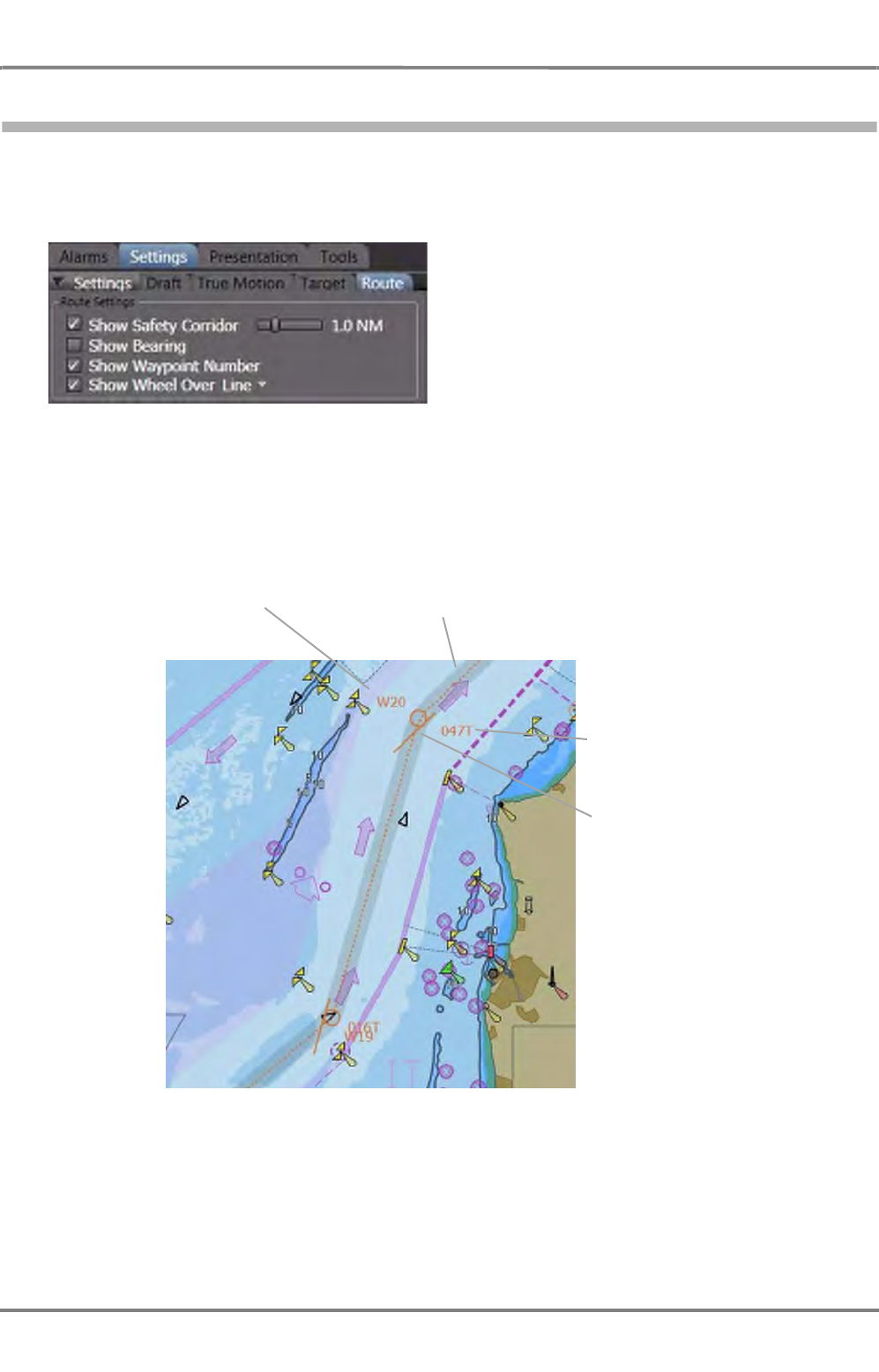
ED 3100 G 140 / 04 (2011-11)
Operating Instructions
C-1 Voyage Planning
C VOYAGE PLANNING & MONITORING.fm C-9
NACOS Platinum
1.1.3 Route Display Settings
Before route editing is started, the settings for displaying the route in the Application Area should be set.
The display options for the route can be set under Settings > Route.
Fig. C / 3 Route Settings
Refer to the following picture to identify the items that can be superimposed as additional information
to the route.
Fig. C / 4 Settings for the route display
Safety corridor, its width
is adjustable.
Waypoint number
Bearing of the leg from
waypoint 20 to waypoint
21.
Wheel over point/wheel
over line.
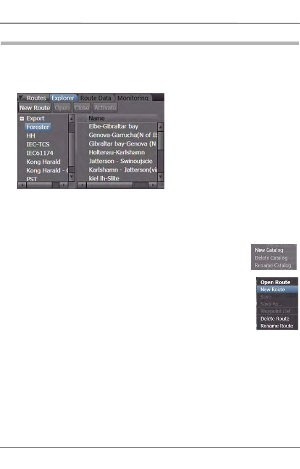
NACOS Platinum
ED 3100 G 140 / 04 (2011-11)
Operating Instructions
C-1 Voyage Planning
C VOYAGE PLANNING & MONITORING.fm
C-10
1.1.4 Route Editing - Graphical
Route functions are started by selecting Tools > Routes > Explorer in the Non-Permanent Area.
The Explorer tab opens the controls for route planning, editing and handling.
This window is also called Route Explorer in this documentation.
Fig. C / 5 Route Editing
From the Folder list, an existing folder can be clicked to be opened, its content is then displayed in the
right part of the window. The names of the routes contained in the folder may be sorted ascending or
descending by clicking the Name control.
It is also possible to create new folders or to erase or rename existing ones. Right-
click in the Folder list to open up the context menu.
☞ The entries Delete and Rename are only possible when a catalog is selected.
To create new routes, click on New Route or open the context menu by right-
clicking in the name list. To delete or to rename existing routes, right click in the Name
list window to open up the context menu.
☞ The entries Open Route, Delete Route and Rename Route are only possible
when a route is selected.
☞ A folder must be opened to be able to edit a new route.
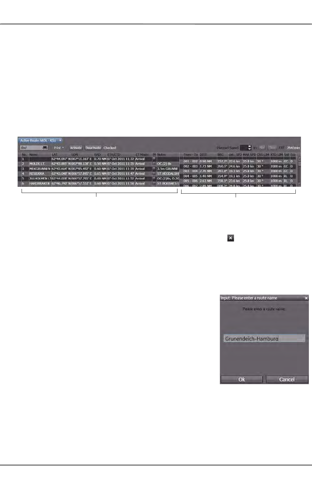
ED 3100 G 140 / 04 (2011-11)
Operating Instructions
C-1 Voyage Planning
C VOYAGE PLANNING & MONITORING.fm C-11
NACOS Platinum
Open an existing route
Mark a route name by clicking on it and then click Open Route, or click on the name in the list and
then open the context menu and click on Open Route.
A route loaded on the MFD can display its waypoints and additional data as a list. For this purpose click
with MORE on the route name and select Waypoint List from the context menu.
If you switch on the waypoint list on the radar, the PPI area will partly be covered by the list. Be aware
that hereby the radar is displayed in a non-approved operating mode. It is therefore recommended to
perform the route plannuing on the ECDIS or on the radar.
Its data is then displayed in the lower part of the application area in form of a waypoint list. The route
is displayed graphically in the application area if the the route is part of the displayed chart area.
Fig. C / 6 Display of Route Data
When you close the Route Tab (i.e. the waypoint list) by a click on the symbol also its display on
the PPI/Chart area will be deleted.
If you want to use the existing route without modification, you must check the route with the existing
system settings before it can be activated as the System Route (See Check Route / System Route.)
Create a new route
In the Name list window right-click in a free space to open the
context menu and click on New Route.
You are then prompted to enter a route name; afterwards the first
waypoint named Initial waypoint appears in the center of the
screen or on the current ship´s position if the ship is centered.
At the same time, you can select Waypoint List from the context
menu so that the Route List window appears in the lower part of the
application area.
Route list
Waypoint list
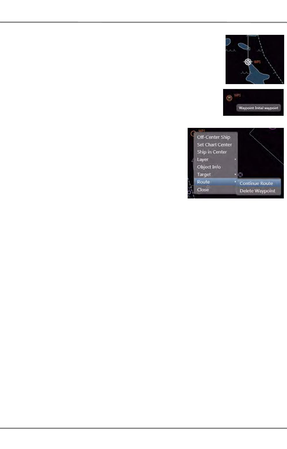
NACOS Platinum
ED 3100 G 140 / 04 (2011-11)
Operating Instructions
C-1 Voyage Planning
C VOYAGE PLANNING & MONITORING.fm
C-12
Click on the waypoint symbol to mark it. The marked waypoint is displayed
with a "handle" and can now be moved to the desired start point of the
route.
Continue Route
To insert additional waypoints, click on the waypoint symbol to
mark it. Then right-click on it to open the context menu.
In the context-menu, click on Continue Route to set the next
waypoint.
From now on the cursor is displayed with a dashed connection
line to the previously set waypoint and each click with DO adds
a new waypoint symbol on the screen. Its position is added at
the end of the waypoint list.
The function Continue Route is also available via the context
menu if you select the first or last waypoint of the route. In this way more waypoints can be added
before the first or after the last waypoint.
Insert a waypoint
To insert a waypoint before or after a specific point of the route, by a click with DO select the waypoint
adjacent to the leg to be modified. Then click on the waypoint select marker with MORE, select Route
in the context menu and click on
- Insert After to create a new waypoint on the leg after the selected point
- or -
- Insert Before to create a new waypoint on the leg before the selected point.
Direct Insertion of a Waypoint on a Leg
Click on the leg to select it; a marker is shown in the middle of this leg. Via the context menu you then
have access to the function Insert Waypoint here.
In any case the new inserted waypoint will be set in the middle of the leg which then must be moved
manually to the wanted position on the screen / in the chart. Alternatively, the wanted position can also
be set or modified directly in the LAT and LON columns of the waypoint list. (See chapter 1.1.5 on page
C-16)
Move a Waypoint
Click with DO on the waypoint symbol to select it. When the selection mark is shown, click on it and
hold the DO key and then move the waypoint symbol to the intended position on the screen.

ED 3100 G 140 / 04 (2011-11)
Operating Instructions
C-1 Voyage Planning
C VOYAGE PLANNING & MONITORING.fm C-13
NACOS Platinum
Add Waypoints
Click with DO on the first or last waypoint symbol of the route. With a MORE click on the selection
marker the context menu is opened. Select Route and click on Insert Waypoint.
Adding a waypoint at the first or last waypoint will create a prolongation of the first / last leg with the
same track course but with 50% of the length of the previous leg; move the added waypoint to the
intended position on the screen to create the correct course and length of the new leg.
Delete a Waypoint
Click with DO on the waypoint symbol to select it. With a MORE click on the selection marker the
context menu is opened. Select Route and click on Delete Waypoint.
Set and Move a Parameter Point
Select the leg of the route displayed on the screen and by a click with MORE open the Route context
menu in the application area. A click on Insert a Waypoint Here first inserts a normal waypoint in the
middle of the leg.
Select the new inserted waypoint in the list (check the waypoint number) and activate the PP (Parameter
Point) checkbox. This waypoint will now be displayed with a small square symbol.
With the graphical cursor on this symbol and pressing down the DO key you can now move the param-
eter point along the preplanned track line. Releasing the DO key will fix the Parameter Point's position
on the leg.
☞ Do not shift the parameter point into the curved part of the displayed route.
Repeat the above procedure in order to add more parameter points on a leg.
☞ Do not shift a new parameter point across already available parameter points.
Note:
The insertion of parameter points on a leg does not create any course change at these points.
With other words, a parameter point is not part of the course change alarm management (No Waypoint
Approach and no Wheel Over Point alarms).
But by use of parameter points you can easily add changes of route parameters like
- Off Course Limit (CRS LIM) and Off Track Limit (XTD LIM)
- Sailing Mode (Sail Mode)
- Rudder Economy (ECON)
- Planned Speed (MAX SPD)
on different parts of a leg.
Changing the planned speed on a leg is done by changing the MAX SPD value, which then also changes
the Calc.SPD value in the Route List.
Save and Save As
In contrast to editing User Symbols (See chapter A - 8 on page A-83), routes and the additional route
parameters shown in the waypoint list are not automatically stored to the file system on the MFD-
computer. Be sure to Save all your changes at the latest after completion of route editing. During long
editing sessions intermediate saving of data is recommended 1).
1) See chapter "Backup/Restore of Map Data" on page H-13 for details on storing data on USB devices.

NACOS Platinum
ED 3100 G 140 / 04 (2011-11)
Operating Instructions
C-1 Voyage Planning
C VOYAGE PLANNING & MONITORING.fm
C-14
If you want do discard your changes made to the selected route, use Save As to store the version with
the changed dataset under a new filename.
Check Route
The route to be used during the voyage must be checked by the program before distribution to the
system.
A not successfully checked route cannot be activated as System Route.
If the selected route shown in Waypoint List in the lower part of the application area shall be used as
System Route and "Not Checked" is indicated behind the check button click on the Check Route button
before activation of the route.
☞ If the route has been reloaded anew, the check results are lost and the check route must be
executed once more. In this way it is ensured that the check is repeated with the actually valid draft
dependent depth contour settings of the most up-to-date electronic chart.
Clicking on the button starts the verification of the pre-planned route as follows:
- check against the Safety Contour
- check against the chart objects with a depth less than the Safety Contour Value
- check against own Safety Lines and Danger Highlight areas.
The results of the route verification are shown in the Waypoint List by small icons in front of the waypoint
numbers. Pointing on it with the cursor, gives additional information on the check-results as a tool-tip.
Clicking on these alarm icons opens another info dialog on the screen, where all detected hazards, limi-
tations, etc. on the leg or at the waypoint are shown and described more detailed. For a step-by-step
guide for route checking See chapter 1.1.7 on page C-25.
System Route
After you have checked it, you can activate the route as pre-planned track by a click on the Activate
button.
In this way the activated route will change its colour from orange to red and will from now on be distrib-
uted to all applications on all MFDs for system-wide use, for example for a connected autopilot or track
control system.
The activated route is from now on handled as System Route until it is deselected again or until another
one is activated.
The System Route has the following properties:
- it cannot be deleted from the screen,
- it cannot be modified or reloaded,
- it is used for chart and track monitoring as set by the operator under > Settings > Route
- it is used for calculation of all data shown in the Route Data window,
- it is sent cyclically to the TRACKPILOT and the (optional) SPEEDPILOT, which use the data of the
System Route for their own calculations and control purposes (see also the relevant chapters of
these operating instructions).

ED 3100 G 140 / 04 (2011-11)
Operating Instructions
C-1 Voyage Planning
C VOYAGE PLANNING & MONITORING.fm C-15
NACOS Platinum
Alternative Routes
Even if you have selected the System Route, it is possible to load other routes from your catalogs and
to display them as well as to edit, modify and save them without interfering with the activated System
Route.
All loaded routes can be displayed with their Waypoint Lists in the lower part of the application area.
Each route has an own tab showing the route name. Clicking on the respective tab of a route brings the
selected Waypoint List into the foreground.
If another route shall be used as activated route, it must be loaded and checked beforehand.
It is sufficient to click on the Activate button on the tab of this route to change the activated route.
In some specific situations in the integrated system it might not be possible to deactivate or change the
currently used System Route. This can be caused by the fact that one of the sub-systems is using this
route for an automatic control function. Examples: Trackpilot in Track mode or Speedpilot in "Arrival
mode".
Previously used routes can be switched off from being loaded and displayed on screen by clicking on the
small cross in the Route Name tab of the waypoint list.
Copy a Route
If you want to create a copy of a loaded route, use Save As... in order to store it under another name
to the same catalogue.

NACOS Platinum
ED 3100 G 140 / 04 (2011-11)
Operating Instructions
C-1 Voyage Planning
C VOYAGE PLANNING & MONITORING.fm
C-16
1.1.5 Route Editing - Text Mode
All inputs for route planning can also be made in text mode, i.e. directly by alphanumeric inputs into the
lines and columns of the Waypoint List and the Route List. 1)
As in the graphic edit mode only the waypoint positions are put into the dataset, in any case all other
additions to the route data must be made in text mode.
Direct entry of data into the waypoint list enables to create a route off-screen, for example in order to
take over a route documented as a list of waypoint positions (LAT / LON data) on a sheet of paper.
☞ If you want to see the loaded or to be edited route on the screen you must switch to ECDIS in
Browse mode and select the respective chart area where the route is located.
Under > Tools > Route create a new route or open an existing route to see the text window of the
route to be worked on in the lower part of the application area.
For this purpose click with MORE on the route name in the Route Explorer and select Waypoint List
in the context menu.
Operating functions in the Waypoint List (Overview)
Selection of a waypoint can be done with a DO click in the waypoint list line by line. In this case the
selected line is shaded blue and in the context menu (click with MORE on the line) the following entries
are provided:
Fig. C / 7 Route Editing - Context Menu
Double clicking on a line in the waypoint list is equivalent to Go to Waypoint in the context menu
and centers the screen in ECDIS / Browse mode to the position of the selected waypoint.
In this way you can jump from waypoint location to waypoint location (i.e. step along the pre-planned
track).
1) Working in the lists is comparable to many commonly used spreadsheet programs; a click into a selected data
cell allows to enter numeric (radius and other parameters) or alphanumeric data (names and notes) within certain
limits. These limits (for example min. and max. radius) are partly depending on configuration data made on
service level.
Go to Waypoint Ctrl + G Corresponds to a double click in the line, see below.
Insert Before
As described in the chapters beforeInsert After
Delete Waypoint
Reverse Order Can reverse the sequence of waypoints (i.e. the sailing direction) 1)
1) The reversed route should be saved under a different name or even a different catalog. Be sure to check
if the waypoint locations can be used unchanged in order to avoid wrong traffic separation zones or sailing
against the recommended sailing direction, etc.!
Copy Waypoint Ctrl + C Copies all data of the selected waypoint to a temporary buffer
Paste Waypoint Ctrl + V Copies the data in the buffer before the selected waypoint.
The selected waypoint is shifted one line down.
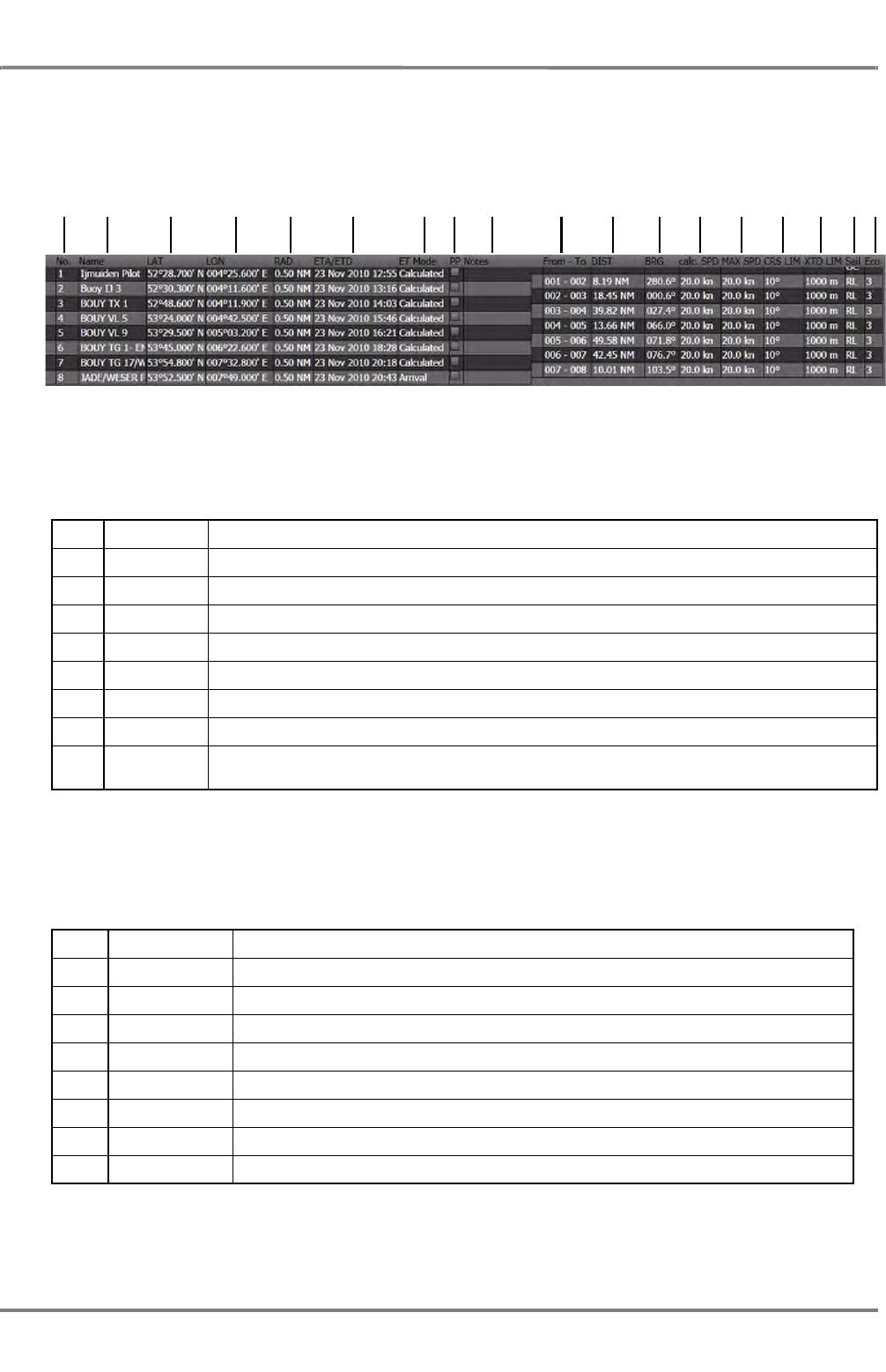
ED 3100 G 140 / 04 (2011-11)
Operating Instructions
C-1 Voyage Planning
C VOYAGE PLANNING & MONITORING.fm C-17
NACOS Platinum
Basic and Additional Parameters of the Route
Referring to the Waypoint and Route List displayed on the screen whenever a route is opened, this over-
view describes in a condensed form the complete parameters stored in the route data-set.
Fig. C / 8 The Waypoint and Route List window
The basic parameters of each route are displayed in the left part of the window, which is also called
Waypoint List.
The additional parameters (calculated or set by the operator during route planning) of each leg of the
route are displayed in the right part of the window, also called Route List 1)
1No. the waypoint sequence number in the route
2Name the name of the waypoint (optional)
3LAT the latitude (N / S value) of the waypoint position
4LON the longitude (E / W value) of the waypoint position
5RAD the radius in NM of the planned turn at the waypoint position
6ETA/ETD the Estimated Time of Arrival or the Estimated Time of Departure at the waypoint position
7ET Mode the calculation method or mode for the ETA (see chapter XYZ)
8PP the selection / indication of Parameter Points 1)
1) Parameter Points are points on a leg of the route without course change but with optional changes of one
or more of the parameters valid for this leg after passing the parameter point. See chapter on page C-13
for details.
9Notes is a field where notes (hints, cautions, warnings or additional info to a waypoint) can be
given in text form
10 From - To the waypoint numbers of the leg
11 DIST the distance between two waypoints (i.e. the length of the leg)
12 BRG the bearing between two waypoints (i.e. the track course of the leg)
13 calc. SPD the calculated speed of advance on the leg (see also chapter "speed calc.")
14 MAX SPD the maximum speed on the leg (set by the operator during route planning)
15 CRS LIM the course limit valid on this leg 1)
1) These parameters are also used by the TRACKPILOT (if installed in your system) in case AUTO Fill is
switched on in the Next Data field on the TRACKPILOT expander. See also chapter TRACKPILOT for
details.
16 XTD LIM the track limit valid on this leg
17 Sail the sailing mode (RL or GC) on this leg (set by operator during route planning)
18 ECON the rudder economy on this leg set for the TRACKPILOT
12 3 4 5 6 789 101112131415161718

NACOS Platinum
ED 3100 G 140 / 04 (2011-11)
Operating Instructions
C-1 Voyage Planning
C VOYAGE PLANNING & MONITORING.fm
C-18
Operating Functions and Settings of the Route Editor in Text Mode
The start-point of route planning in text mode is the same as in graphic mode.
Click on Tools, Routes, Explorer in the non-permanent expander, select a folder (i.e. a catalog) and select
New Route or select Open Route if you want to modify an existing route.
The following description defines the steps necessary to create a new route in text mode starting from
scratch. The operation steps relevant for modifying a previously created route are identical.
New Route
You are prompted to enter a name for the new route before you can continue.
The command New Route opens an empty waypoint list where the so called Initial Waypoint is auto-
matically set to the center of the visible screen automatically. The created LAT/LON value should be
moved or set to the intended start position.
Waypoint List
Click on Waypoint List in the context menu of a route name to open the waypoint list in the application
area.
Edit the first Waypoint
Click with DO on the initial waypoint line to select it. By a click in the LAT and / or LON field open the
position input and key in the intended value of the start position.
Enter a default or specific Radius
Click with DO on the initial waypoint line to select it. By a click in the RAD field open the radius input
and key in the intended radius value in nautical miles. The radius can be set between the minimum and
maximum radius specified for the system on service level.
Please refer also the chapter Predefined Radius under Useful Information on page C-20.
With the radius set to another value than 0.00 NM the next following waypoints in the list will automat-
ically inherit the same value until another value is set in one of the following Radius columns of a
waypoint.
Add a Waypoint / Insert After
Click with DO on a waypoint line to select it. By a MORE click open the context menu. There click on
Insert After; this will create a new waypoint with a distance to the previous one whereby the same
course of the leg will be used.
Then click the LAT and LON fields to correct the position. If required also key in a new radius value in
the RAD field after clicking it.
Add a Waypoint / Insert Before
Click with DO on a waypoint line to select it. By a MORE click open the context menu. There click on
Insert Before; this will create a new waypoint in the middle of the leg with the same radius than set
for the previous waypoint.
Then click the LAT and LON fields to correct the position. If required also key in a new radius value in
the RAD field after clicking it.
1) The offset of ½ line between Waypoint and Route List indicates the validity of the data on the leg between the
two adjacent waypoints.

ED 3100 G 140 / 04 (2011-11)
Operating Instructions
C-1 Voyage Planning
C VOYAGE PLANNING & MONITORING.fm C-19
NACOS Platinum
Move a Waypoint by LAT/LON input
Click with DO on the waypoint line to select it. By a click in the LAT and / or LON field open the position
input and key in the intended modified position. You may also move the waypoint graphically in the PPI/
Chart area.
Delete a Waypoint
Click with DO on the waypoint line to be deleted. After another click into the line with MORE the context
menu opens where you can select Delete Waypoint.
Copy and Paste
Selecting a line and with a MORE click and selection of Copy Waypoint in the context menu, all data
of the selected waypoint are copied to a buffer. With Paste Waypoint a new waypoint will be created
before this or another selected line.
Taking over from another Route
Select another route from any available catalog and copy the required waypoint. Then change back to
the route to be modified and use the Paste Waypoint function of the context menu in order to insert
the copied waypoint before any selected line.
Taking over of a complete Route
Load a route from any available catalog and save it to the same or another folder.
In another folder you may use the same name of the route; in the same folder you must use another
name before saving it in order not to overwrite the original data.
The function Save As... is supporting this task.
☞ For the general functions Save and Reload, Check Route, System Route and Alternative
Routes as well as Reverse Route please refer to the respective chapters under graphical route
editing.
Useful Information
ECDIS and Browse Mode
- During route editing it is often advisable to use the Browse mode of the ECDIS. In this way you can
at the same time observe the geometric constraints (for example: too large radius, too short leg,
etc.) and the numerical parameters of the route when you establish the waypoint sequence.
- In Browse mode, by a double-click on the line of a waypoint dataset, the display screen of the appli-
cation area (PPI or chart) is automatically centered on the selected waypoint. I.e. by clicking line by
line you can "jump" along the route from waypoint to waypoint.
- In Browse mode you can also use the Zoom and Pan control or the other tools in the permanent
area (like Range) and the application area (like Set Chart Center, etc.) to control the scale and the
center position of the electronic chart.
General Note about Editing
All alphanumerical input fields are opened in the overwrite mode, i.e. you can directly type in the wanted
value. If you only want to change a part of the value, click before the character or number to be changed
and make your entry.
The Enter key or button, or a click somewhere else takes over the input you have made.
NACOS Platinum
ED 3100 G 140 / 04 (2011-11)
Operating Instructions
C-1 Voyage Planning
C VOYAGE PLANNING & MONITORING.fm
C-20
If the data input verification results in an error state, you will be asked by the system to change your
data entry.
Some of the columns do not have alphanumeric entries but
- a selection menu (ETA/ETD: Arrival, Departure) or
- a check box or
- a selection bar (ECON).
Predefined Radius
- Already during editing the route, it is advisable to enter a radius for the first waypoint. This radius
will be copied to all other added waypoints until you set another radius. In this way it can be verified
"on-line" during editing if geometric constraints (matching of length of the legs, radius, and amount
of course change) are violated.
- It is recommended first to use a sort of "default" radius for sailing with nominal speed which could
later be adjusted for your needs and depending on the results of the verification of the route on the
chart display. The default radius should create a rate of turn far below the maximum rate of turn
you would normally accept for your ship under the planned loading conditions.
- The predicted steady state turn-rate at a waypoint caused by the planned radius can easily be esti-
mated by the calculation
ROT [°/min] ~ sailing speed [kn] / radius [NM]
Table C / 1 Route Editing - Predefined Radius
Speed Radius ROT
[estimated]
25 kn 1.00 NM ~ 25 °/min
25 kn 0.50 NM ~ 50 °/min
12 kn 1.00 NM ~ 12 °/min
10 kn 0.10 NM ~ 100 °/min
Be sure not to plan too small Radius values at high speed which would cause too
high and possibly dangerous turn-rates on your ship. 1)
1) The maximum ROT and the minimum allowed radius at nominal speed should have been
defined during the sea trials. Both values are parameters of the system configuration on service
level. The radius input during route planning is limited by the parameters min. and max. radius.

ED 3100 G 140 / 04 (2011-11)
Operating Instructions
C-1 Voyage Planning
C VOYAGE PLANNING & MONITORING.fm C-21
NACOS Platinum
Check Route Corridor
- with Safety Corridor
The pre-planned route can roughly be checked during editing already if an appropriate Safety Corridor
is selected under Settings > Route. The displayed corridor around the route helps to support the oper-
ator during creation of the route when the display area covers the sea area of the route or of parts of it.
At any time during editing the width of the safety corridor can be adjusted for the visible part of the
route. In any case it is then valid for the complete route.
If you use a new route for the first time it could be sufficient to define a general minimum passing
distance (for instance 250 m or another safe value) in order to be on the safe side when the program
checks the route for the first time.
Details, like adapting the radius, the track limit and other values could be adjusted following the
messages about violations after the route checking function has been executed.
- with Track Limit
The pre-planned route contains a track limit (XTD LIM) which can be set differently for each leg of the
route. By parameter points it can even be changed one or more times on the same leg.
By adapting the different track limit entries in the route to the sea area to be passed, you can support
the built in route monitoring function as much as possible. In this way it is ensured that respective ECDIS
alerts are given, when the cross-track alarm is activated under the Alarms > ECDIS Alerts expander.
When the route is used for sailing with TRACKPILOT in Track Mode, deviations from the pre-planned
track are activating respective alarms depending on the sea area and traffic separation zones.
Imported Routes
Imported route data taken over from the so called map/track data files of previous RADAR- or NACOS
system generations can also be used again in the Platinum system.
The track number of those tracks will be used as a part of the route name.
For instance the track number 1330 and the track name STO_HEL will be combined to the route name
"1330 STO_HEL" in the new system.
For details how to import/export your own user made symbols, see chapter 1.1.9 on page C-34.
For details how to import/export your maps/tracks, see chapter 2.9 on page H-13.

NACOS Platinum
ED 3100 G 140 / 04 (2011-11)
Operating Instructions
C-1 Voyage Planning
C VOYAGE PLANNING & MONITORING.fm
C-22
1.1.6 Details of the Waypoint Data
This section gives an overview about the meaning and use of all parameters and data being part of the
route data-set. The shortcuts in parenthesis [ ] are those used in the headlines of the Waypoint and
Route List on the screen.
Waypoint Number [No.]
Meaning: Serial number of a waypoint within the route; it is automatically allocated consecutively by the
program, beginning at 1. It clearly identifies the waypoint within the route. It appears as a reference
marker in all lists, in the chart area (if switched on), and in all other displays of the system which refer
to the individual waypoint.
Name of the Waypoint [Name]
Meaning: Helps to identify the waypoint during the subsequent processing and during use while sailing
along the route. It can be displayed or printed out in all lists, and can be shown in most displays of the
system which refer to the individual waypoint.
Waypoint Position [LAT] [LON]
Meaning: Geographical WGS84 position of the waypoint
Editing: In the [LAT] and [LON] column.
Special features during editing: The hemispheres are input with N, S and E, W.
Radius [RAD]
Meaning: Radius in nautical miles with which the planned course change manoeuvre at a waypoint is to
be performed. It can be set between the minimum and maximum radius value defined for the system
on service level.
Estimated Time of Arrival / of Departure [ETA/ETD]
Meaning: Indication of the manual set or automatically calculated estimated time of arrival or departure
time depending on the ET Mode set in the following column.
Estimated Time Mode [ET Mode]
Meaning: Defines the method how the ETA/ETD data are calculated by the system.
Editing: Under ET Mode in the Waypoint List; can be set to Departure / Arrival / Calculated.
If it is set to Calculated, no input can be made into the ETA/ETD column. If you do not want to use the
Planned Track Speed function, the point of departure should be set to Departure, any point of arrival
should be set to Arrival.
Parameter Point Attribute [PP]
Meaning: With the aid of a waypoint for which the Parameter Point attribute is set, new values for the
route parameters Maximum Speed, Course Limit, Off Track Limit and Rudder Economy can be set differ-
ently within a straight track segment (the leg of a route).

ED 3100 G 140 / 04 (2011-11)
Operating Instructions
C-1 Voyage Planning
C VOYAGE PLANNING & MONITORING.fm C-23
NACOS Platinum
Waypoint Notes [Notes]
Meaning:
Here, you can input information and instructions for the nautical personnel, which can be displayed on
the MFD while the ship is sailing on the leg to this waypoint.
The consecutive waypoint notes shown on the screen can be used as an automatic notebook or can also
be printed on in different list formats 1).
These waypoint notes, on operator request, also appear in the Chart Information Window on the
chart (together with other waypoint related data).
Note:
If you use an alphanumeric keyboard during editing, in the Notes window you can "cut and paste" the
text or parts of it for use in the same route for another waypoint (cut = Ctrl+C; paste = Ctrl+V).
From and To Waypoint [From - To]
Meaning: This column indicates the numbers of the From and To Waypoints, i.e. the leg designation
between waypoint N and N+1. The columns following in the same line in the Route List are valid for this
leg.
Waypoint Distance [DIST]
Meaning: This column indicates the distance in nautical miles between two consecutive waypoints, i.e.
the length of the track segment between the From-waypoint and the To-waypoint. The calculation
includes the curved track line defined by the radius and the course change at the waypoint.
Waypoint Bearing [BRG]
Meaning: This column indicates the bearing of the track line between two consecutive waypoints, i.e. the
course over ground to be steered on the straight part of a track segment.
Calculated Speed [calc. SPD]
Meaning: This is the speed that is calculated for the track segment between two consecutive waypoints;
it is calculated once for the Planned Speed mode or continuously in ETA Mode.
- In ETA mode (i.e. an arrival time has been set):
While the ship is sailing along the track, this speed is continuously computed and limited on the basis of
the Max. Speed values.
- In Planned Speed mode (i.e. the Planned Track Speed has been set):
After the planned speed value has been Set by the operator, this speed is computed once for each leg,
whereby the calculated values are limited by the Max. Speed values.
In any case the Calculated Speed is the speed with which the ship will have to sail in order to reach
the destination at the planned estimated time of arrival and which can be used as the speed setting by
the optional SPEEDPILOT in Arrival Mode.
Because the Calculated Speed is continuously shown in the Route List display window, it can also be
adopted as a set point for the manual speed setting via the propulsion lever by the officer of the watch.
1) Printing functions and Waypoint Notes displays are not yet available in the system.

NACOS Platinum
ED 3100 G 140 / 04 (2011-11)
Operating Instructions
C-1 Voyage Planning
C VOYAGE PLANNING & MONITORING.fm
C-24
Maximum Speed [MAX SPD]
Meaning: The Maximum Speed defined for a leg is used by the system as the speed limitation for the
Calculated Speed between each From waypoint and To waypoint (i.e. each leg).
This limitation by the MAX SPD values takes place leg by leg with manual setting of the Planned Track
Speed as well as during the frequent recalculation in ETA mode.
Course Limit [CRS LIM]
This route parameter is only relevant in systems equipped with a TRACKPILOT.
Meaning: Alarm limit of the TRACKPILOT for the difference between set course and actual course (the
course deviation). It also influences the possibility of switching the TRACKPILOT over to Track mode and
the corrective actions performed by the TRACKPILOT if the ship deviates from the track, see chapter "G
- TRACKPILOT" on page G-1.
Track Limit [XTD LIM]
Meaning: Alarm limit of the system for the deviation from the route (the off-track distance to the track
line is indicated as XTD in meters). The track limit also influences
- the ECDIS monitoring, see Section 4.4
- the checking of deviations from the System Route.
- the possibility of switching the TRACKPILOT over to Track mode,
- the control precision of the TRACKPILOT in Track mode,
- the filtering and monitoring of the external position-data by the TRACKPILOT in Track Mode.
Sailing Mode [Sail]
Meaning: This setting specifies whether the track segment between two waypoints is to be computed
and used as the basis for steering with the TRACKPILOT and displayed on the chart as a Great Circle
or as a Rhumb Line.
The default setting defined by the program is the Great Circle mode (a new route starts with GC mode
on each leg). In contrast to a Rhumb Line, which is steered with constant course, on a Great Circle track
the entire distance is shorter and small course changes are about to happen when the ship is following
the pre-planned GC track.
Rudder Economy [Eco]
Meaning: Optimization of the TRACKPILOT between precision of control and frequency of rudder move-
ment, depending on the prevailing conditions like the sea state and the wind. Low values for Eco means
high rudder gains and vice versa (see chapter "G - TRACKPILOT" on page G-1).
To simplify manual adjustments during use of the TRACKPILOT, this value should only be entered for
the first waypoint and at the boundary between a protected area (harbour, river, canal) or other confined
waters and an unprotected area (open sea).

ED 3100 G 140 / 04 (2011-11)
Operating Instructions
C-1 Voyage Planning
C VOYAGE PLANNING & MONITORING.fm C-25
NACOS Platinum
1.1.7 Checking of Routes
This chapter contains the detailed back-ground knowledge and a step-by-step instruction about the
checking of routes during their creation with the Route Planning tool and before using them as the
System Route.
A necessary prerequisite for achieving the required safety in the use of the pre-planned track is that,
before being used, the route is carefully checked. This check should take place immediately after the
route has been created or changed, i.e. before storage, and it must be repeated each time after a route
has been reloaded from the memory.
☞ A route which has not been checked by the program cannot be activated as the System Route.
During this check, the track lines and the radius based track curves must be subjected to a geometrical
check and a check against the electronic chart and the User Symbols (i.e. the user made chart
objects). These checks must take place one after another under program control. The geometrical check
is already done during editing, while the verification against the electronic chart and the user made chart
objects is done with the actual safety settings each time the check function is called by the operator.
The check against the electronic chart is started by clicking the Check button in the route- and
waypoint list (also called route window in this chapter). Before the start of the check against the elec-
tronic chart it is necessary to create the conditions for the execution of the check against the electronic
chart and the User Symbols; see chapter 1.1.7.2 on page C-29.
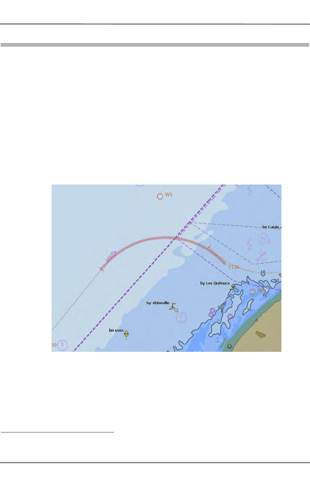
NACOS Platinum
ED 3100 G 140 / 04 (2011-11)
Operating Instructions
C-1 Voyage Planning
C VOYAGE PLANNING & MONITORING.fm
C-26
1.1.7.1 Geometrical Check
This check takes place already during route editing and it is independent of the used electronic chart or
the availability of user made chart objects. It only verifies if the geometric construction of the straight
track lines and the track curves calculated from the different planned radius values are fitting together.
Possible construction errors are:
- A radius is too short, i.e. shorter than the lower limit value that was set for it at service level.
If no radius was input at the first waypoint, the program uses a default value 1) as the input value
for all radii, which must be changed to the required value by the operator.
- A radius is too long, i.e. longer than the upper limit value that was set for it at service level.
- A radius is too long, so that the distance to the next waypoint is too small that the curve planned
in this way does not fit and can probably not be executed with this radius at this waypoint.
- There is a parameter point situated in the curve area of the track. To make certain that the changes
made by means of the parameter point are indeed effective in the desired track section, parameter
points should generally be located outside the curve area.
Fig. C / 9 Radius at waypoint 5 does not fit
1) For the time being the default radius is the average between min and max radius, which have been set on service
level.
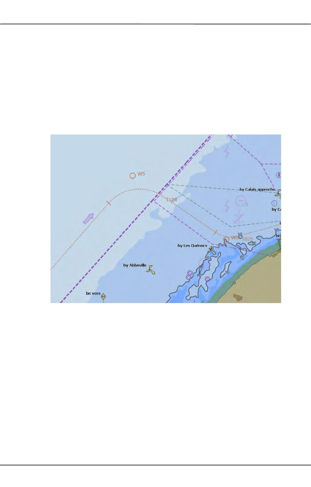
ED 3100 G 140 / 04 (2011-11)
Operating Instructions
C-1 Voyage Planning
C VOYAGE PLANNING & MONITORING.fm C-27
NACOS Platinum
How the geometrical errors are made visible during editing:
- If the Safety Corridor is not switched on during route editing, the only visible fault indication is
the unexpected shape of the track line and the fact that the track curve is not shown at the right
place. In any case the curved path will be calculated and shown on the screen with the correct
radius as set in the waypoint list. Curves not fitting correctly are shown with a red stripe
- If you perform the Check Route function during editing, the results of the route check are made
visible by displaying alarm or warning icons in the route list for segments which are erroneous.
- Additionally, in case of not corrected errors, clicking on the Activate button opens a detailed fault
description including the relevant waypoint numbers and the erroneously checked route will not be
accepted as System Route.
Fig. C / 10 Modification of waypoint 5 and 6, both radius values reduced
Correcting the Route
If a part of the pre-planned track is not displayed correctly or if it is marked with a red coloured stripe,
a fault message is given or an alarm icon is shown in the route window, the following can be performed
to correct the faults:
- In the waypoint list, the concerned line to which the fault message refers can be double-clicked in
order to show it in the center of the display area.
- For the purpose of error free editing, you can modify the relevant section of the route directly on
the screen or you can correct its numerical data in the route window.
If appropriate, modify the relevant waypoint or parameter point positions and / or the radius and verify
the route again.
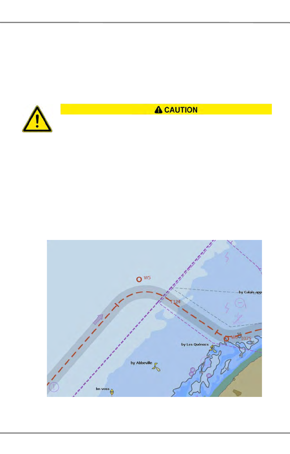
NACOS Platinum
ED 3100 G 140 / 04 (2011-11)
Operating Instructions
C-1 Voyage Planning
C VOYAGE PLANNING & MONITORING.fm
C-28
As soon as
- a waypoint has been added or deleted,
- one of the waypoints or parameter points has been moved or modified, or
- a radius value has been changed
the route is automatically being marked unchecked in the status field adjacent to the Check Route
button. Thereafter the route must be checked again.
Continuing / Ending the Check
If none of the graphical fault indications or messages mentioned appears any more, the check against
the electronic chart and the user made chart objects (User Symbols) can be started now.
If the check against the electronic chart and the User Symbols was prepared beforehand and done
already in parallel to the geometrical check of the editing process, the route should be stored; it can now
be used by the system without reloading it.
☞ In any case, before later reuse of a previously planned route, the check against the eventually
updated chart and the possibly modified User Symbols must be repeated after the relevant settings
for the Safety Contour and Own Safety Lines or Danger Highlights have been verified or adapted to
the prevailing conditions (see also the following chapter).
Fig. C / 11 Modified route, activated as System Route, displayed with Safety Coridor
As long as the route under construction shows any fault and is not readily
corrected, it should not be stored in the catalogs normally used for voyage execu-
tion in order to prevent any unintended use by other users of the system.
ED 3100 G 140 / 04 (2011-11)
Operating Instructions
C-1 Voyage Planning
C VOYAGE PLANNING & MONITORING.fm C-29
NACOS Platinum
1.1.7.2 Check against the Electronic Chart and the User made Chart Objects
This chapter contains details and a step by step instruction how to perform the check of the geometrically
correct route against the electronic chart, the optional raster charts or paper charts.
This verification of the planned route against charted objects must be performed before it can be made
the System Route. After each reload or any change of a route the checking must be repeated after the
relevant safety settings (Safety Contour) have been adapted to the prevailing conditions.
Preparation
1. In the menu Presentation > ENC > Depth, set the Safety Contour correctly
2. Set the type of the electronic chart against which the check is to be performed, preferable to ENC.
3. Switch on the display of the user made symbols, lines and areas in the context menu of the PPI/
Chart area under Layer > User Symbols.
4. Adjust the Range setting so that cells of the electronic vector chart or raster charts 1) which contain
the nautically relevant information for the planned route are displayed.
5. If a vector chart is used, check whether chart cells having the appropriate navigational purpose are
present for the entire track, at least over the width corresponding to the Safety Corridor setting
or to the Track Limit contained in the route data-set:
• Correctly set the display of the chart objects in the ENC that are to be displayed
• With the Set Chart Center or the Pan and Zoom Control function, step along the route to
be checked.
For those chart areas of the planned route which are not covered by suitable data cells, all nautically
relevant objects along the route must be marked by means of Own Safety Lines or Danger High-
lights.
To verify this, also the raster charts can be used if installed on your system - see step 6.
If there is no suitable raster chart available, the check must be performed manually against the
paper chart. For this purpose, the pre-planned track, including the track limits, must be entered in
the paper chart and checked on that chart visually.
6. If raster charts are used, then 2) all nautically relevant objects along the route must be marked by
means of own Safety Lines or Danger Highlights for the entire track, at least over the width corre-
sponding to the track limit.
For this purpose, virtually sail along the route to be checked using the Set Chart Center or the Pan
and Zoom Control functions.
1) Raster charts are not yet available in the PLATINUM system.
2) This is prescribed for ships with DNV approval and using raster charts.
The checks mentioned in steps 5 and 6, and the editing of the own chart objects,
especially of the own safety lines and danger highlights, must be performed with
care so that the necessary level of safety can be achieved.
NACOS Platinum
ED 3100 G 140 / 04 (2011-11)
Operating Instructions
C-1 Voyage Planning
C VOYAGE PLANNING & MONITORING.fm
C-30
Performing the Check
The check against the electronic chart must be started manually after the geometrical check was
successful. In this check, after a click on the Check Route button, the geographical shape of the track 1)
is compared with the data of the vector chart and with the user chart objects Own Safety Line and
Danger Highlight.
For the execution of the check, the display settings mentioned above under
Preparation
are not important.
What is important is the selection of the type of electronic chart and the setting of the Safety
Contour 2), see also above under Preparation.
For the verification of the route, the chart cells with the highest precision available on the system are
used as the basis. They might therefore differ from the cells used for the display. Because of this,
messages might occur which initially contradict the presentation of the pre-planned track in the vector
chart 3).
The results of the verification process are made visible
- in form of red rings shown along the route
- by small alarm icons in front of the lines in the waypoint and route lists.
Pointing on the colour markings in the chart or on the alarm icons in the list opens the respective tool
tips describing the detected violation between the route and the electronic chart (if vector charts are
used) and the user made chart objects.
Correcting the Track
Select ECDIS and Browse mode to be able to verify the complete route on screen.
If a waypoint is double clicked or it is selected and then in the context menu Go to Waypoint is clicked,
the respective waypoint to which the message refers is shown at the centre of the chart area.
Verify the causes for the violation and decide about the changes to be made to avoid it.
If appropriate, modify the relevant segment of the route and start the check again.
When the entire pre-planned track is shown without red ring symbols along the route and no alarm icons
are shown any more in route window, the check program did not find any violations.
☞ It may happen that errors or warnings remain displayed but in reality there is no serious problem
going along that route. The quality of the check-results is mainly depending on the contents of the
electronic charts.
1) The track considered during checking also includes the area corresponding to the actually set Safety
Corridor.
2) The Safety Contour information of the ENC or other vector charts is not available in raster charts and must
therefore fully be replaced by manually generated Own Safety Lines and Danger Highlights.
3) To clarify supposed contradictions of this kind, it is helpful to switch to a different range setting and to use
the Chart Info box where required.
Vector charts which have not been approved for navigational use or were not
updated by the user might contain errors.
Successful checking of the route on the basis of such vector charts does not guar-
antee that the ship can sail safely along the route.
It is under the responsibility of the operator to use a planned route for navigation,
irrespective if it was checked by the system successfully or with errors.

ED 3100 G 140 / 04 (2011-11)
Operating Instructions
C-1 Voyage Planning
C VOYAGE PLANNING & MONITORING.fm C-31
NACOS Platinum
1.1.7.3 Computation of Sailing Times
The system computes the sailing times that will occur if the track is sailed at a Planned Speed or at a
variable speed, depending on the Departure Time and the Arrival Time (planned time of arrival).
In both cases it also calculates the effect of a speed limitation set by the route parameter MAX SPD
available for each leg of the pre-planned track. This computation is done each time when you enter a
route parameter which is changing the route distances, the relevant speed values or the ETA/ETD values.
- If you set the Planned Speed for the complete voyage, the system calculates a time schedule
based on the speed settings contained in the planned route. It results in the displayed estimated
time of arrival (ETA) for each waypoint in the route and the entire sailing time under ETE.
- If the planned time of arrival (ETA) is input at the beginning of the voyage, the system performs
a speed calculation for the complete route. This calculation is based on the Departure and Arrival
Time set for the planned route, and its purpose is to display the required speed for each leg in
order to achieve the required time of arrival at the end of the route.
- In both cases, the result, the calculated speed for each leg, is displayed under calc. SPD in the
Route List, and can be used by the operator as the current speed setting during manual speed
control. The calculated speed values are in any case limited to the MAX SPD values which may be
defined differently for each single leg of the entire route.
- Additional to the time and speed data in the waypoint and route list, and independent of the calcu-
lation method the estimated time elapsed (ETE), i.e. the entire sailing time will be displayed to the
right of the Planned Speed controls.
- In a system equipped with SPEEDPILOT, the calculated speed values of the route can also be
controlled automatically while the ship is sailing along the pre-planned track. In this case each calcu-
lated speed value of a leg will be used as the set-point for the speed controller and the planned
time schedule is thus fulfilled, if nothing unforeseen happens in between.
Initial Time Schedule
If you load or reload a route, or a new one has been created, the program will set all calc. SPD values
to maximum speed (i.e. to the MAX SPD values contained in the route). At the same time a time schedule
will be calculated based on these speed values and the first and last waypoint will contain the implicitly
resulting departure and arrival time.
Time Schedule with ETA
In order to adapt the initial time schedule of the route to your demands perform the following steps:
1. Select the departure point from the waypoint list and in its ET Mode field set the mode to Depar-
ture.
2. Enter time and date of departure in the ETA/ETD field; this will result in an adapted time schedule,
using the speeds shown in the calc. SPD column.
3. Select the arrival point from the waypoint list and in its ET Mode field set the mode to Arrival.
4. Enter time and date of arrival in the ETA/ETD field.
This will result in an adapted time schedule by changing the speeds shown in the calc. SPD column but
keeping the departure time.
As long as the MAX SPD values of the planned route are not achieved, the adapted time schedule will
follow your settings for the ETD and ETA (refer also to the Notes below).

NACOS Platinum
ED 3100 G 140 / 04 (2011-11)
Operating Instructions
C-1 Voyage Planning
C VOYAGE PLANNING & MONITORING.fm
C-32
Time Schedule with Planned Speed
In order to adapt the initial time schedule of the route to a constant speed for the entire route or to a
specified speed profile, perform the following steps:
1. Select the arrival point and in its ET Mode field set the mode to Calculated.
2. Verify or change the maximum speed values in the MAX SPD fields according to your needs.
3. In the Planned Speed field enter the required speed value and click on Set.
This will result in a new calculation of the time schedule for the entire route based on the set departure
time and the planned speed value, but taking into account those legs which have a speed limitation set
by the MAX SPD values.
If the route contains an arrival point in the ET column and the Planned Speed is entered, you will get a
warning that this will be changed to Calculated and the arrival time is lost.
With [Clear] you can make the Planned Speed invalid, so that the time schedule can be recalulated
based on the set arrival and departure times.
Notes:
If the maximum speed is achieved in all calc. SPD columns, the arrival time cannot be made shorter.
In this case an earlier arrival time will also lead to an earlier departure time. In the same way a later
departure will create a later arrival time.
If you must achieve an earlier arrival time and an earlier departure is not possible, the MAX SPD values
could be increased until an upper limit is reached, which is specific for your ship under the prevailing
conditions.

ED 3100 G 140 / 04 (2011-11)
Operating Instructions
C-1 Voyage Planning
C VOYAGE PLANNING & MONITORING.fm C-33
NACOS Platinum
1.1.8 Completing the Generation of the Route
The new or modified route must be stored in the file system of the MFD so that the data that were input
during or after checking of the route will not be lost as soon as the route is switched off or the system
is shut-down.
Ending the Generation of a New or Modified Route
The route window must be switched on and visible.
1. You can enter additional notes to each single waypoint in the Note input fields of the waypoint list.
2. In the header of the waypoint list or in the context menu of the Route Expander click on [Save]
and the new or modified route data-set will be stored with all data which have been entered until
then under the indicated Route Name.
☞ If you have modified a route and want to keep the original route unchanged you must enter another
route name for the original route before you save the modified one. This is done by a MORE click
into the catalog field of the Route Explorer where Save As... must be clicked. When specifying
the route name, pay attention to the following:
- Each route is assigned to a catalog. Within the catalog, the route is clearly identified by
means of the route name, i.e. within a catalog the same route name can only be assigned
once.

NACOS Platinum
ED 3100 G 140 / 04 (2011-11)
Operating Instructions
C-1 Voyage Planning
C VOYAGE PLANNING & MONITORING.fm
C-34
1.1.9 Import / Export Routes

ED 3100 G 140 / 04 (2011-11)
Operating Instructions
C-2 Chart and Route Monitoring
C VOYAGE PLANNING & MONITORING.fm C-35
NACOS Platinum
2 Chart and Route Monitoring
During the voyage, the ECDIS subsystem of each MFD integrated in the navigation system performs a
number of nautical checks at short intervals of time. This process is running on all indicators with RADAR-
PILOT 1) and ECDISPILOT functionality as well as on the MULTIPILOT.
If defined criteria, based on the ECDIS performance standards, are infringed, an appropriate alarm is
given when the respective monitoring function is in the switched on state under the relevant alarm
settings.
The entire implemented monitoring functionality can be divided into route monitoring and chart moni-
toring.
Route monitoring
- is performing the monitoring of deviations of your own ship from the System Route, displayed in
the PPI/chart and
- is watching the approach to critical points on the System Route.
Additionally the results of the Check Route function in combination with the monitoring strip defined by
the Safety Corridor remain available to the operator for the System Route also during voyage execu-
tion.
Chart monitoring
is including the checks of own ship's position (defined by the ship's outline 2)), its movement ahead in
course direction (defined by the Look Ahead Sector) relative to
- the chart objects contained in the vector chart and
- the user chart objects Own Safety Line, Danger Highlight and many of the symbols 3) which are
available in the User Symbols database.
Alarms and Warnings for activation of the different monitoring functions are selected in the Alarms
expander via the ECDIS Alerts selection menu. The alarms can be activated independently by selection
of
- Safety Contour Alarm
- Special Area (Indication or alarm)
- Obstruction ahead indication
- Critical point on route alarm
- Cross-track alarm
in the Alerts menu.
1) On RADARPILOT Chart Monitoring is only possible if it is configured as a Chartradar on service level.
2) The parameters for the ship´s outline have been defined on service level.
3) Only those user-made symbols which are classified as obstructions (like buoys, beacons, lighthouses, landmarks,
etc.) generate an alarm in the monitoring process.

NACOS Platinum
ED 3100 G 140 / 04 (2011-11)
Operating Instructions
C-2 Chart and Route Monitoring
C VOYAGE PLANNING & MONITORING.fm
C-36
An alarm given in the Alarm Line and in the Alarm List and referencing chart objects ahead or at the
own ship's position can be caused by several different violations of chart objects being touched or
crossed:
- Each basic alarm reason (i.e. each type of object related alarms) creates a circular symbol showing
the location of the violation by the own ship contour or the look ahead sector.
- Holding the cursor on the circular symbol, opens the chart alarm list with detailed descriptions for
this location. The additional alarm text information is taken from the chart database (i.e. is part of
the official electronic charts) or from the user made own chart objects.
Preconditions
So that this Chart Monitoring can serve its purpose, namely increasing the nautical safety, the following
prerequisites must be fulfilled:
- The best possible sensors for position and speed over ground must be selected.
- By means of a comparison between the available position sensors, a check must be performed to
ensure that the selected position sensor is supplying correct and accurate position data.
- If a vector chart is used, it must be available for the entire navigated area. Otherwise, own safety
lines and danger highlights must be made available in the User Symbols data base for the missing
areas.
- If a raster chart is used, own safety lines and danger highlights for all potentially dangerous areas
and objects must exist for the entire navigated area.
- The safety contour value must have been set correctly. See chapter 5.7 on page B-57 for details.
- The used route must have been successfully checked and reasonable settings for the track limit (i.e.
the monitoring strip for the deviation from route alarm) must have been made for each leg.
- The latest relevant nautical warning information received by radio must be taken into account,
possibly by the editing of own safety lines or danger highlights or by manual ENC update (see
chapter Chart Maintenance).
- The check of the used planned route should, if necessary, be repeated after incorporation of the
received warning information.
- The alarm criteria must be correctly set - see the following sections.
- In the case of doubt and once per year, the monitor performance must be checked. See chapter B
- 3.3 on page B-14 for details.

ED 3100 G 140 / 04 (2011-11)
Operating Instructions
C-2 Chart and Route Monitoring
C VOYAGE PLANNING & MONITORING.fm C-37
NACOS Platinum
2.1 Route Monitoring: Own Ship against the System Route
Monitoring of the Cross Track Distance
If the deviation of the own ship's position from the pre-planned track is greater than the Cross-track
alarm limit set in the System Route under XTD LIM for the current leg, the alarm message Deviation
from Route appears.
The activation of the relevant alarm function takes place under Alarms > ECDIS Alerts > Cross-track
alarm. The off-track limit value currently valid for the actual leg is displayed in the XTD LIM column of
the route list. The currently measured off track distance (i.e. the transverse deviation from the track line)
is indicated numerically on the Route Data Expander and graphically on the Conning Display 1) .
Alarm on Approaching the present Waypoint
When the probable travelling time needed to reach the wheel over point (WOP) of the next planned
course manoeuvre at the To-Waypoint defined by the System Route becomes less than the value of
the look ahead distance or the time displayed under Alarms > Own Ship, the alarm message
Approach to Waypoint appears.
In addition, by switching off the function Critical point on route alarm, the output of this alarm can
be suppressed for this MFD, even if the other route related alarms are not suppressed.
USEFUL INFORMATION
The Connection with the TRACKPILOT 2)
The monitoring of the own ship against the System Route is performed independently of the ECDIS sub-
system by the TRACKPILOT as well (if the TRACKPILOT is switched on). During this process, both
programs operate with independent limit-values.
The TRACKPILOT always checks with its own user set limits against the track which is valid for its oper-
ating mode, i.e. depending on its steering mode (Heading, Course or Track mode). The equivalent route
related alerts of the TRACKPILOT are only activated if the ship is steered automatically in Track mode
(i.e. along the System Route).
For the case that the AUTO Fill function is activated, the TRACKPILOT will also use the XTD Limit taken
from the System Route, i.e. the same value as used for route monitoring by the ECDIS sub-system.
In case of course or position deviations from the pre-planned track and depending on the situation, the
alarms TP Course Limit Exceeded and TP Track Limit Exceeded are given, and the approach to the
WOP is announced by the TP Waypoint Approaching alarm.
Additionally, 30 seconds before starting a course change in Track mode, the TP WOP Execution alarm
will be given by the TRACKPILOT.
☞ The order to reduce the number of alarms during sailing in Track Mode, it is advisable to switch off
the Cross-track alarm and the Approach to Waypoint alarm of the ECDIS.
1) The Conning Display is an optional system component or an optional display mode on the MFD.
2) This information is not relevant for systems without TRACKPILOT.
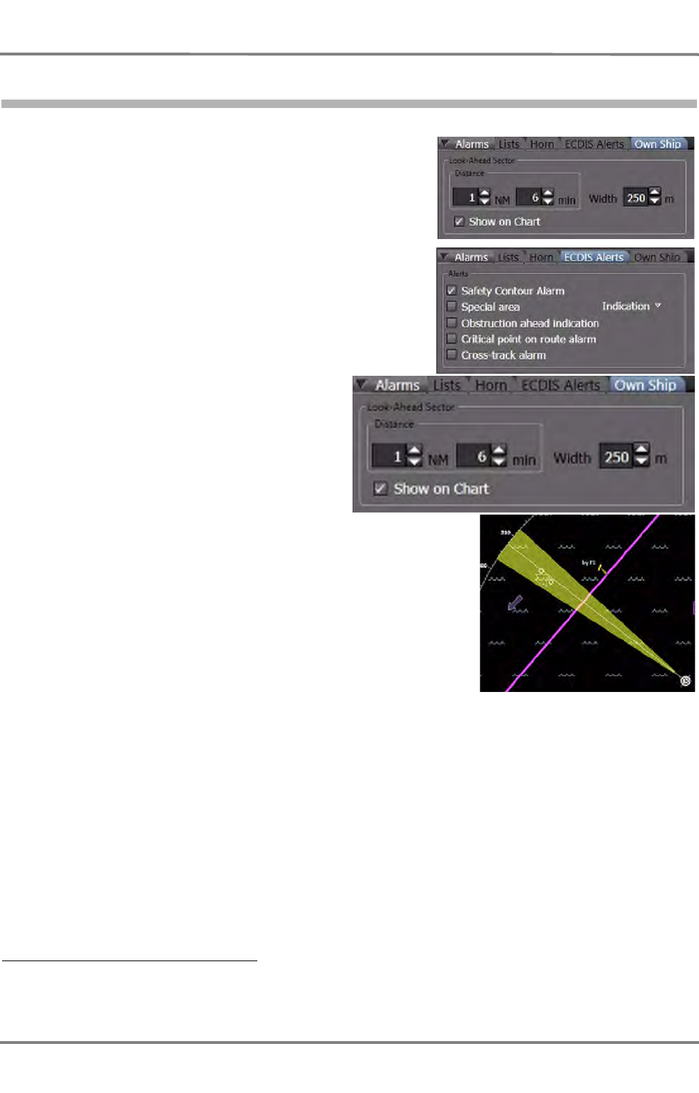
NACOS Platinum
ED 3100 G 140 / 04 (2011-11)
Operating Instructions
C-2 Chart and Route Monitoring
C VOYAGE PLANNING & MONITORING.fm
C-38
2.2 Chart Monitoring: Own Ship against Vector - / User Chart Objects
Look-Ahead Sector/Alerts
Two different expanders provide a collection of settings
usable for chart and route monitoring during voyage
execution. The route related alerts are only activated if a
System Route has been activated for the system.
Look-Ahead Sector
Show on Chart activates a virtual sector in
front of the ship, formerly known as "guard
sector".
For this ECDIS Monitoring function and inde-
pendent of the visibility of the sector, the
program constructs a monitoring sector (look
ahead sector) with an adjustable sector width
and a length which can be defined here.
In the example shown here, the sector has a
length of one mile and a width of 250m at its
end 1).
The guard sector opens out from own position
in the direction of the ship's movement (i.e. the
COG/SOG vector) and is carried along with the
ship.
The monitoring is performed both with the
guard sector and with own position (i.e. the
own ship contour).
It takes place for several objects which are entered in the electronic chart or are stored as User Symbols.
The monitoring is therefore independent of whether the display of these objects is switched on or off.
Which chart objects or which user symbols are to be monitored is specified in the relevant performance
standards.
Whenever a monitored object is within the defined range of the sector or it touches or overlaps the
ship´s contour, the corresponding alarm is raised. See below under Alerts.
☞ Even when the function Show on Chart is switched off, in any case the defined guard sector moni-
tors against the objects under Alerts in the frame below.
It might be an advantage to suppress the guard sector monitoring if the speed is very low or the ship
is stationary.
1) The Look-Ahead Sector length can be defined by a time or a distance setting, whereby the value resulting in
the longer distance ahead will be used. With the time setting, the length of the guard sector is dependent on the
own ship´s speed.
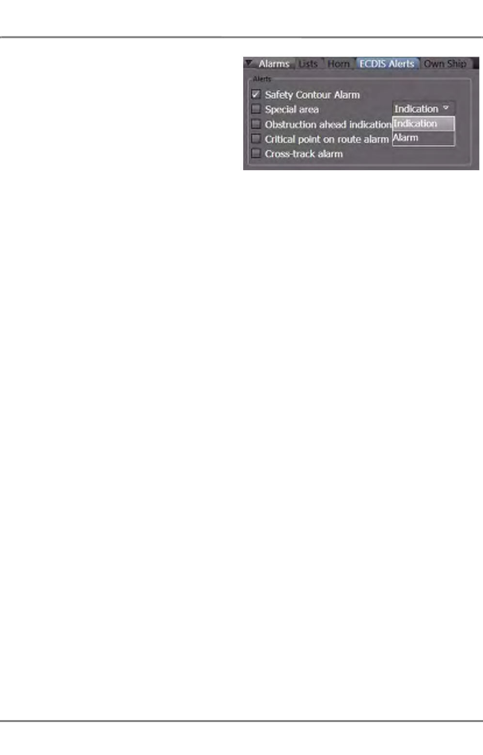
ED 3100 G 140 / 04 (2011-11)
Operating Instructions
C-2 Chart and Route Monitoring
C VOYAGE PLANNING & MONITORING.fm C-39
NACOS Platinum
Alerts
Different alerts can be switched on and
adjusted for the purpose of own ship and route
monitoring.
- If selected, Safety Contour Alarm
raises the Crossing Safety Contour
alarm. For the setting of the Safety
Contour see See chapter 5.7 on page B-
57.
- If selected, Special Area raises the Area
with Special Conditions alarm.
☞ It can be chosen wether this notification will be raised as an alarm with buzzer or as an indi-
cation only.
- If selected, Obstruction ahead indication raises the Crossing a Danger indication.
- If selected, Critical point on route alarm raises the Approach to Waypoint alarm.
If in the switched on state, this alarm will be announced automatically before your ship is passing
the next waypoint on the activated route. The pre-warning distance or time can be set under Alarms
> Own Ship > Look-Ahead Sector. See chapter C - 2.2 on page C-38 for details. The waypoint
Notes field in the opened waypoint list can be used to transfer information concerning this point
on the route to the operator.
- If selected, Cross-track alarm raises the Deviation from Route alarm if the maximum allowed
cross-track distance between pre-planned track and current position is exceeded. The monitoring
limit can be set during route editing in the XTD LIM column of the waypoint list. See chapter C -
1.1.6 on page C-22 for details)
Switching the Alarms on
Click on Alarms, ECDIS Alerts to switch the different monitoring functions on or off. These selections
can be done independently of each other.
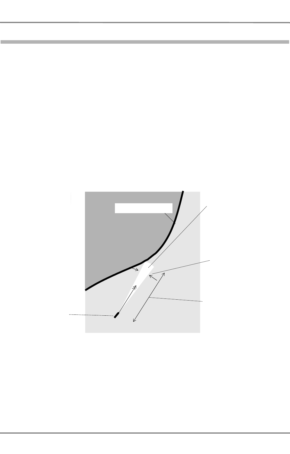
NACOS Platinum
ED 3100 G 140 / 04 (2011-11)
Operating Instructions
C-2 Chart and Route Monitoring
C VOYAGE PLANNING & MONITORING.fm
C-40
2.2.1 Monitoring on the Basis of a Vector Chart
Warning against Sailing into an Area of Insufficient Depth
When a Safety Contour (See chapter 5.7 on page B-57) or another area with insufficient depth (less
than the set safety contour value) is touched by the guard sector, e.g. an object belonging to the object
class Land Area, the Crossing Safety Contour alarm appears in the alarm list. As soon as the own ship
contour is situated on the safety contour or on one of the other above-mentioned areas, the alarm like-
wise appears.
The safety contour is formed from all objects of the object classes Land Area and Intertidal Area and
from the objects of the object classes Depth Area or Dredged Area whose depths are equal to or the
next size greater than the value entered in the menu Presentation > ENC > Depth under Safety
Contour.
For this monitoring, the cells with the highest precision available in the chart database are used. They
might be different from the cells being used for display. It is therefore helpful to use another display
range for an additional visual check and to use the Info Box.
The setting of the guard sector for this monitoring process is performed in the same way as described
above in the menu Alarms > Own Ship. The output of the safety contour alarm can be generally
suppressed by means of the Safety Contour Alarm checkbox under Alarms > ECDIS Alerts .
Fig. C / 12 Generating the Chart Alarm with the Guard Sector (example: Safety Contour alarm)
Guard sector moves along
with the ship and its direction
is always the same as the
ship's direction of movement
(the guard sectorcan be
displayed on the screen)
Ahead Sector Length as set in
Alarms > Own Ship under
Distance
Safety contour
Ship's position when the
Crossing Safety Contour
alarm occurs
Ahead Sector width, set in the
Alarms > Own Ship menu

ED 3100 G 140 / 04 (2011-11)
Operating Instructions
C-2 Chart and Route Monitoring
C VOYAGE PLANNING & MONITORING.fm C-41
NACOS Platinum
Warning about Running over a Potentially Dangerous Object
If the guard sector touches an object from a series of object classes specified in the program based on
the ECDIS Performance Standards, such as Restricted Area, Caution Area, Traffic Separation Zone or
Buoys, Beacons, etc., the alarm Area with Special Conditions or Crossing a Danger appears in the
Alarm List. These alarms also appear if objects are touched which belong to particular object classes and
are provided with depth information (e.g. Underwater Rocks, Wrecks) and whose depth is less than the
value entered under Safety Contour in the menu Presentation > ENC > Depth.
The setting of the guard sector for this monitoring process is performed in the same way as described
above in the menu Alarms > Own Ship. There, the output of the above mentioned alarms can be
generally suppressed by means of the checkboxes Special Area and Obstruction ahead indication.
For the Special Area alert monitoring, the priority in the alarm list can be set to alarm or to indication
level. Indications are announced without activation of the buzzer.
NACOS Platinum
ED 3100 G 140 / 04 (2011-11)
Operating Instructions
C-2 Chart and Route Monitoring
C VOYAGE PLANNING & MONITORING.fm
C-42
2.2.2 Monitoring against User Symbols
If an Own Safety Line is touched or crossed by the guard sector, the Obstruction Ahead alarm
appears in the Alarm List. The alarm appears only if the own safety line is touched from within the safe
area. The non safe side of the area behind the safety line is indicated by small hachure lines.
The same alarm is issued if one of the user-made Symbols (e.g. buoys, beacons, wrecks or other under-
water hazards) is touched by the look-ahead sector.
If an area belonging to the object class Danger Highlight is touched by the guard sector, the alarm
Area with Special Conditions appears.
Activation of the guard sector for this monitoring of the user-made chart objects is performed in the
menu Alarms > ECDIS Alerts where also the other alarms can be activated or suppressed.
User Chart Objects on Raster Charts
☞ Because the user-made own safety lines, danger highlights and symbols are available independently
of the chart type, this part of the chart monitoring process can also be performed if raster charts
are used 1).
It is urgently recommended 2) that, if raster charts are used, the dangerous areas and objects and
(for example) traffic separation zones should be marked by means of own safety lines or danger
highlights in order to support the navigator with a basic automatic chart monitoring function.
USEFUL INFORMATION
Details of the Chart Monitoring Alarms and Indications
Supplementing information about the chart monitoring results is shown in combination with a circular
symbol in the chart or by opening the Info window at this location after clicking with MORE into the
chart. If you hold the cursor on a circular symbol, a tool-tip window is shown, containing the chart alarm
list with all violations found in the chart at this position.
Repetition of the Alarms
If, for example, the ship is sailing along a line of buoys and is too close to them, the alarm Crossing a
Danger appears only for the first buoy, but it can be acknowledged and remains in the alarm list until
this type of violation is no longer found within the guard sector. Thereafter a new violation can activate
the same alarm again.
1) Raster Charts are not yet available in the Platinum ECDIS
2) On ships with DNV approval this is a compulsory requirement.
An alarm is only repeated if an object belonging to a different object class is
touched or if the same object class is touched within a smaller distance or time.

CONNING


NACOS Platinum
ED 3100 G 140 / 04 (2011-11)
Operating Instructions
D-1 Operating the Conning
D CONNING.fm / 10.11.11
D-3
1 Operating the Conning

NACOS Platinum
ED 3100 G 140 / 04 (2011-11)
Operating Instructions
D-1 Operating the Conning
D CONNING.fm / 10.11.11
D-4
1.1 General
The functionality of Conningpilot is available in the system in different implementations
- On the second monitor connected to a main MFD. In this case operation is executed by the same
keyboard and trackball which is connected to the main MFD, by moving the cursor to the screen
area of the second monitor.
- As one of the additionally available operating modes on a MFD.
In general, different conning display functions can be configured for different conning monitors, but the
operation of each display function is identical on all screens.
Depending on the system configuration the conning display can present and operate functions for navi-
gation, automation, machinery, maintenance and service.
For a description of conning functions of Automation/Machinery please refer to ....
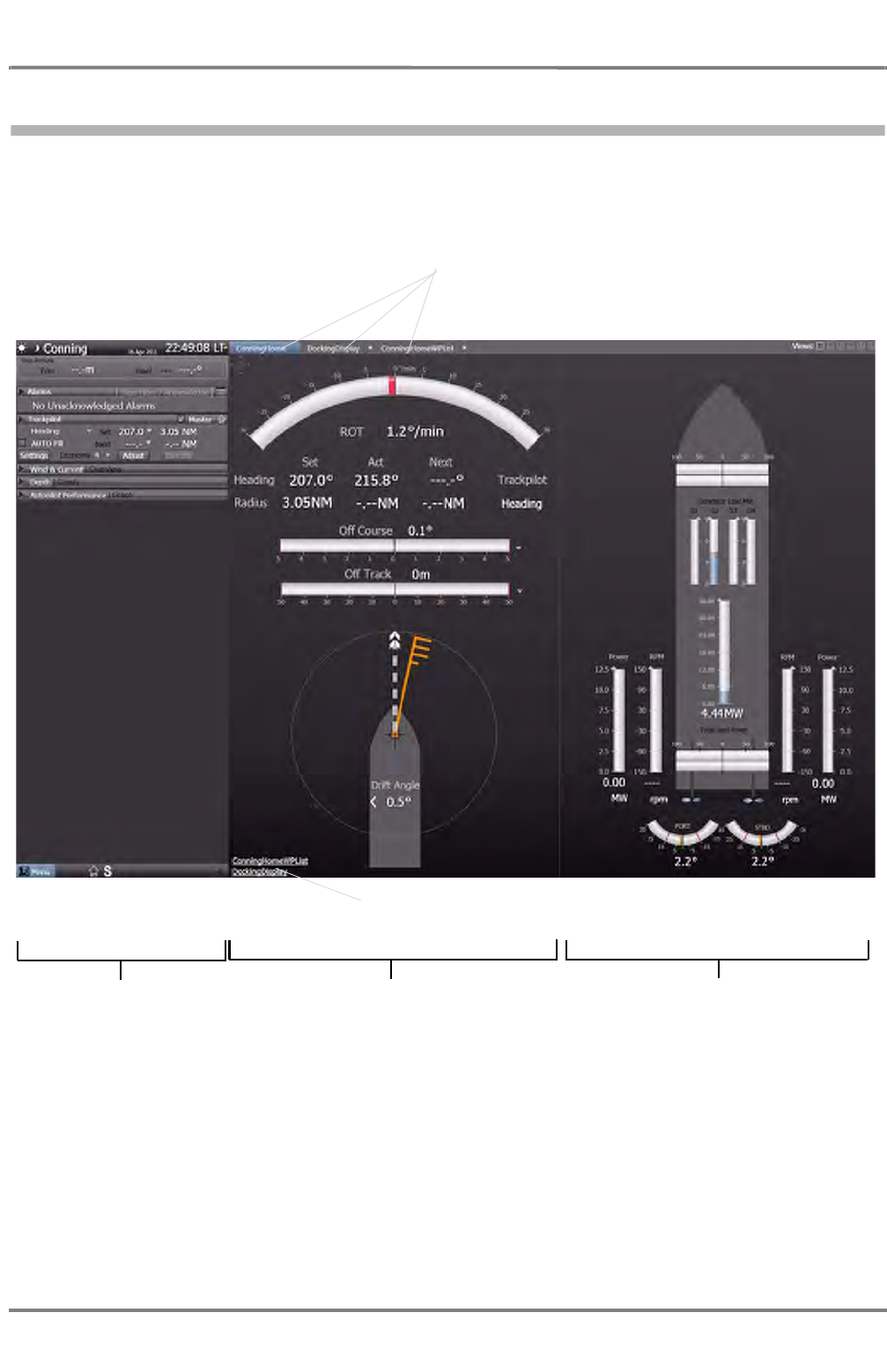
ED 3100 G 140 / 04 (2011-11)
Operating Instructions
D-1 Operating the Conning
D CONNING.fm / 10.11.11 D-5
NACOS Platinum
1.2 An Overview of the Screen
Similar to each other screen layout, the conning display window is devided into different screen areas
which can be combined in different ways.
Fig. D / 1 Overview of the Conning screen
As a minimum, three different views of the Conning screen are available:
- Conning Home. It shows the most important conning data for open sea navigation according to
the settings of the operator. It is divided into a Navigation part and an Automation part.
Display area for navigational data. Display area for automation data. This
area can be configured relating to the
set-up of the ship.
Sidebar with permanent
and non-permanent area
Tabs for the quick access to the appropriate
windows, available after the window has
been displayed at least one time.
Links for the quick access to the appropriate
windows

NACOS Platinum
ED 3100 G 140 / 04 (2011-11)
Operating Instructions
D-1 Operating the Conning
D CONNING.fm / 10.11.11
D-6
- Conning Display Waypoint List provides a combination of the most important conning data and
the actual waypoints of the present system route. It is divided into two parts as well.
- Docking Display. In this display, the movement of the ship is visualised with detailed data for
heading, rate of turn and speed.
Other Display selections may be available depending on the ent system configuration and the available
sensors and interfaces.
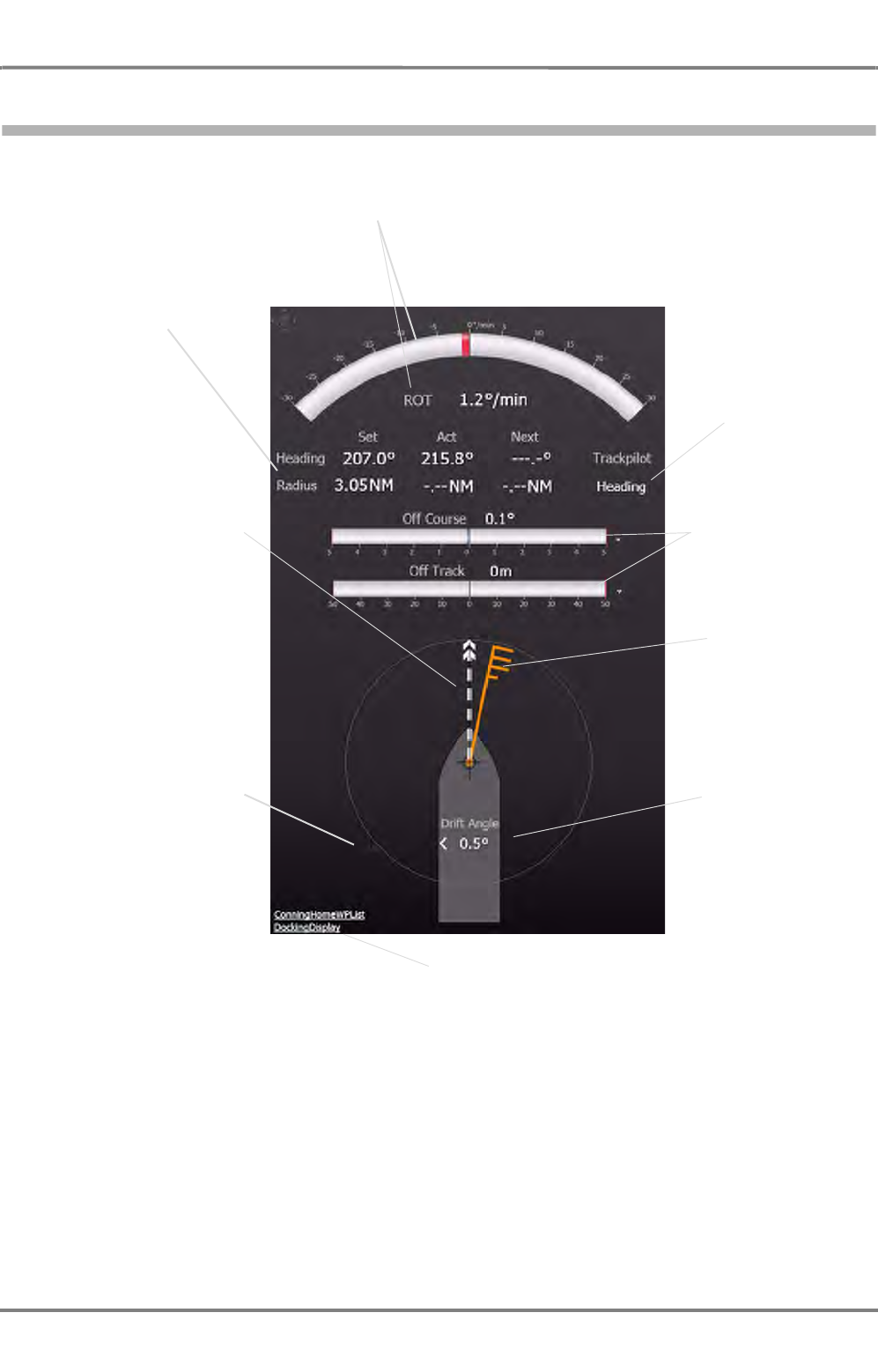
ED 3100 G 140 / 04 (2011-11)
Operating Instructions
D-1 Operating the Conning
D CONNING.fm / 10.11.11 D-7
NACOS Platinum
1.3 Conning Display - Navigation
Fig. D / 2 Conning Display
The Conning Display - Navigation is displayed together with the automation data in the Conning Home
window. The window is opend per default when Conningpilot is started, it is also accessible by the appro-
priate tab or link. For the automation part of this display see chapter D - 1.6 on page D-10.
Rate of turn numerical value and
graphic indication
Heading indication with the
Set, Actual and Next values
used by the Trackpilot in
Heading mode.
Indication of the direction
of the speed vector. The
vector starts at the
System Position. See
chapter 2.1 on page III-16
for details.
Trackpilot operating
mode
Off Course/Off Track-
numerical value and
trend indicator
Wind direction and
speed indication
Drift angle value and
direction indicator
calculated by the
Trackpilot.
Indication of the maximum
value representing the
length of the speed vector.
The speed vector over
ground is true to scale until
5 kn. Above 5 kn the
length is limited and repre-
senting a direction only.
Links for the quick access to the appropriate
windows
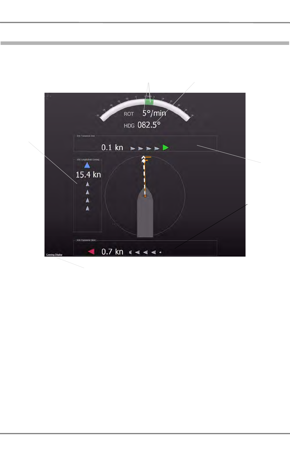
NACOS Platinum
ED 3100 G 140 / 04 (2011-11)
Operating Instructions
D-1 Operating the Conning
D CONNING.fm / 10.11.11
D-8
1.4 Docking Display
Fig. D / 3 Docking Display
The Docking Display is shown in the entire Application Area.
In the example above, bow is moving transversal in starbord direction, stern is moving to port. The direc-
tion is indicated by the green and red triangles respectively at the appropiate side of the display as well
as by the light-grey arrows, which are moving into the appropriate direction.
Rate of turn* numerical value and
graphic indication. Green and red for
STBD/PORT turning direction. Actual gyro heading
Bow and stern
transversal
speed indica-
tors, numer-
ical value and
graphic indica-
tion. Green
and red for
STBD/PORT
turning direc-
tion.
Longitudinal
speed indica-
tion, numer-
ical value
graphic indica-
tion.
Links for the quick access to the appropriate
window.
* : The indicated ROT value (numerical and graphics) is calculated by the system from the gyro-heading received
from the selected heading sensor.
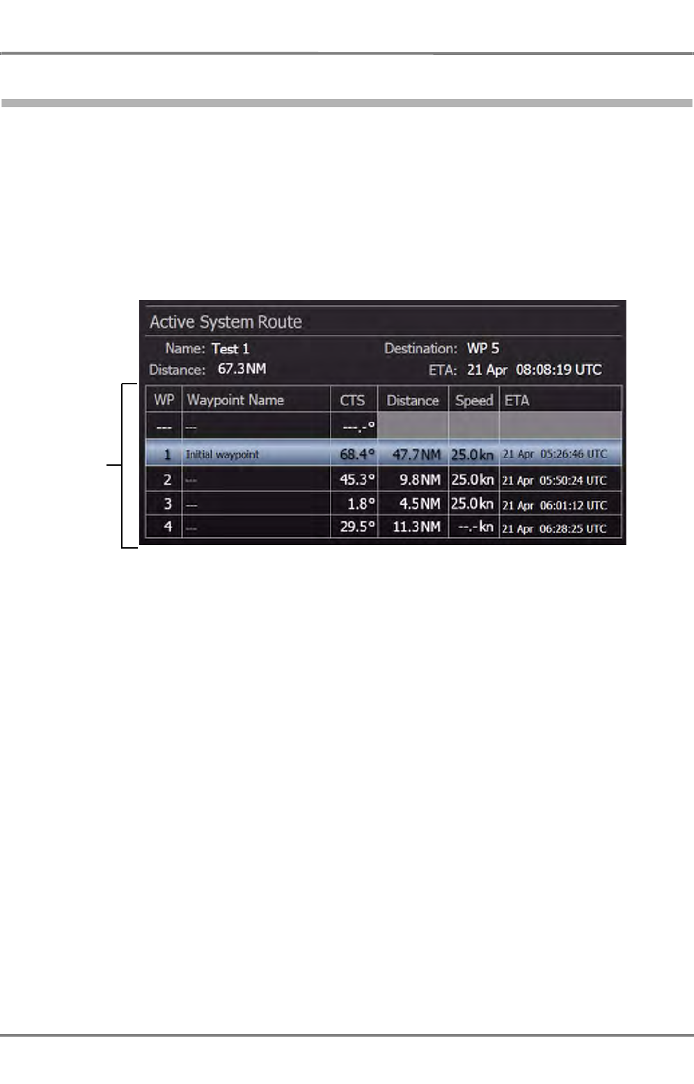
ED 3100 G 140 / 04 (2011-11)
Operating Instructions
D-1 Operating the Conning
D CONNING.fm / 10.11.11 D-9
NACOS Platinum
1.5 Conning Home Waypoint List
☞ Subjcect to changes, ot yet described
Fig. D / 4 Conning Home Waypoint List
The upper part of the Conning Home Waypoint List is similar to the main conning display, but the
outline of the ship and the ship´s speed vector and wind indication are replaced with a table that displays
the data of the Active System Route.
The waypoint list shows the courses, leg distances and calculated speed data for the actual next legs of
the route. The ETA-column indicates the arrival times at the waypoints calculated by the system. Addi-
tionally, the planned and actual ETA at the specified Arrival point is shown together with the calculated
Delay or Spare time of the time schedule.
Active System
Route data
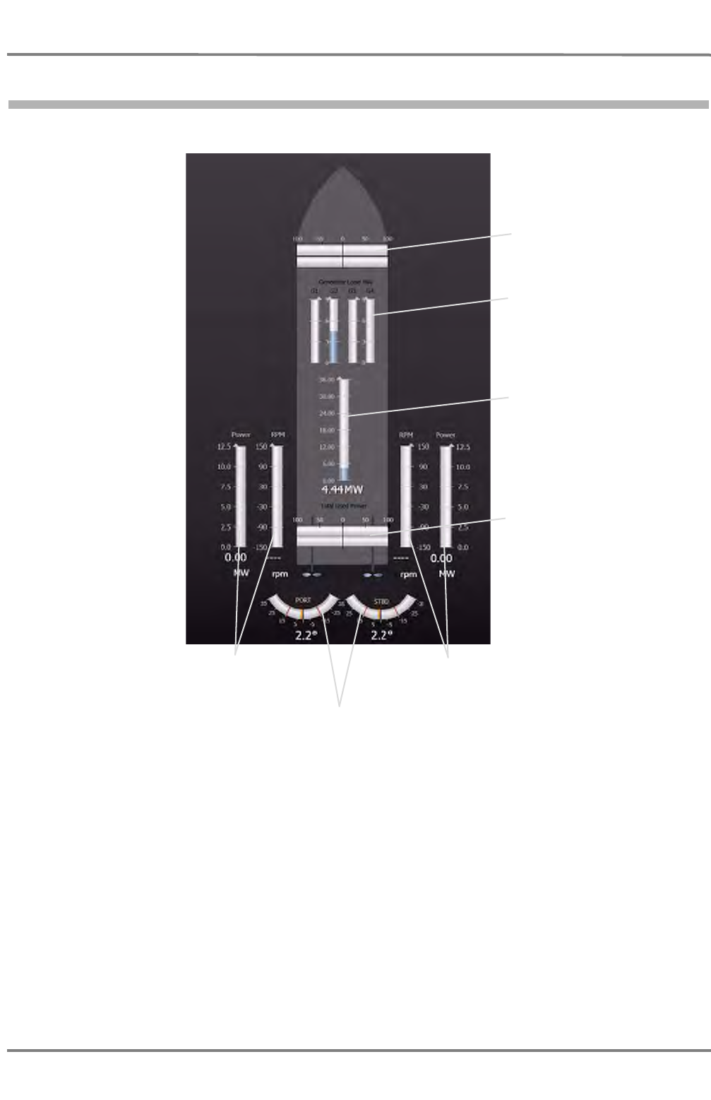
NACOS Platinum
ED 3100 G 140 / 04 (2011-11)
Operating Instructions
D-1 Operating the Conning
D CONNING.fm / 10.11.11
D-10
1.6 Conning Display - Machinery
Fig. D / 5 Conning application area for automation data
The Conning Display - Machinery is displayed together with the navigation data in the Conning
window. The window is accessible by the appropriate tab or link. For the automation part of this display
see chapter D - 1.6 on page D-10.
☞ The figure above is only an example. It may vary significantly from the display on your system!
Rudder angle from the rudder angle sensor.*
The thin red lines indicate the rudder limit set by
the operator with the configuration manager
tool.The orange line indicates the set value of the
active Trackpilot.
Shaft power and revolution
speed of the port main
engine
Shaft power and revolution
speed of the starbord main
engine
Stern thruster power and
thrust direction in %
Bow thruster power and
thrust direction in %
Electrical power delivered
by the generators
Total electrical power deliv-
ered by the generators
* : In systems withTrackpilot. Values delivered by the Trackpilot Interface.
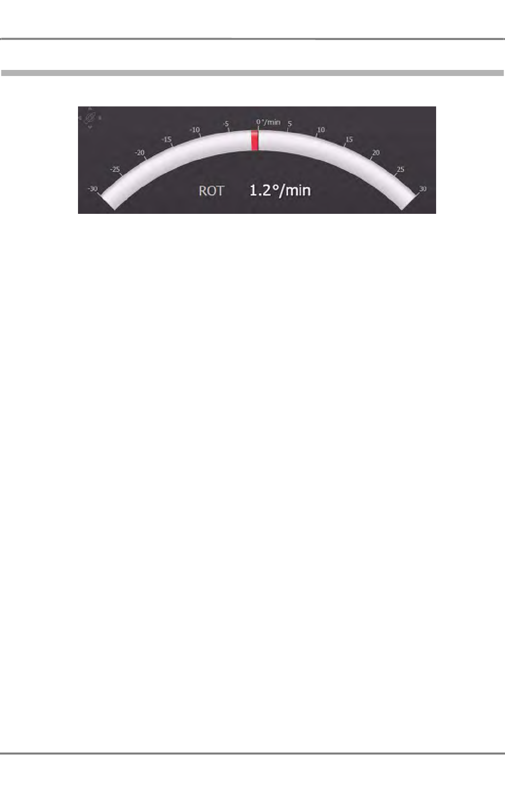
ED 3100 G 140 / 04 (2011-11)
Operating Instructions
D-1 Operating the Conning
D CONNING.fm / 10.11.11 D-11
NACOS Platinum
1.6.1 The Rate of Turn Indication
Fig. D / 6 The Rate of Turn Indication
The Rate of Turn value is computed from the change in the gyro heading values supplied by the
compass system. Displayed as numerical value and graphical indication.
Red bar to the left: Ship is turning to port.
Green bar to the right: Ship is turning to starboard.

NACOS Platinum
ED 3100 G 140 / 04 (2011-11)
Operating Instructions
D-1 Operating the Conning
D CONNING.fm / 10.11.11
D-12
1.7 Conning Sidebar - Permanent Area
The permanent area consists of only one group, the Ship Attitude.
Fig. D / 7 Conning Sidebar in the Permanent Area
- Heel
The transversal inclination of a vessel due to the action of the wind, a greater weight upon one side,
etc., usually transitory. Positive values indicate a heeling to STBD.
- Trim
The longitudinal inclination of a vessel due to greater weight at the bow or stern, etc., usually tran-
sitory. Positive values are present if the bow is "up".
The Ship Attitude window may, depending on sensor availability, also contain the Draft forward (at
bow) and the Draft aft (at stern).
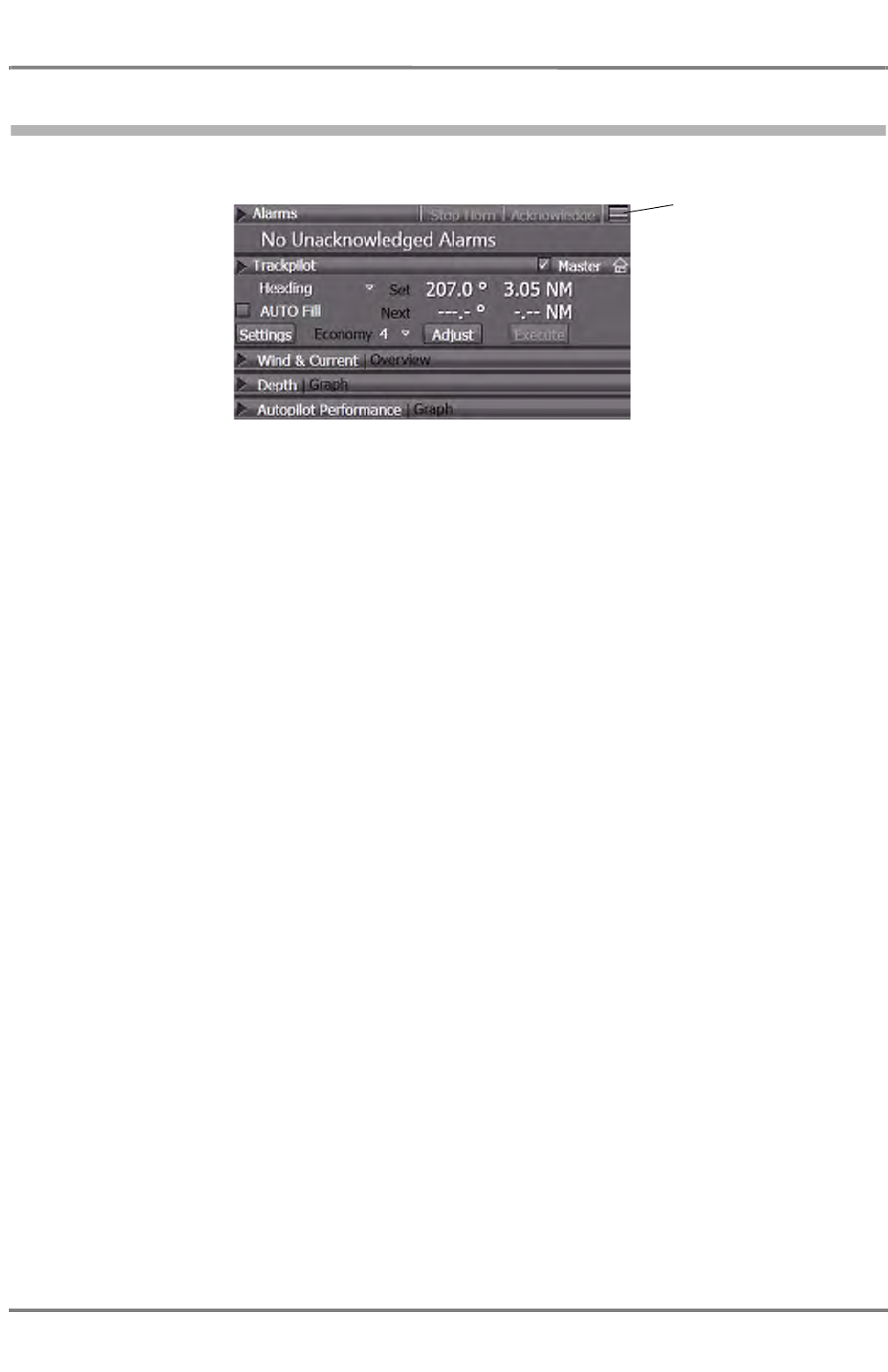
ED 3100 G 140 / 04 (2011-11)
Operating Instructions
D-1 Operating the Conning
D CONNING.fm / 10.11.11 D-13
NACOS Platinum
1.8 Conning Sidebar - Non-permanent Area
Fig. D / 8 Conning Sidebar in the Non-Permanent Area
- The Alarms expander shows the oldest not acknowledged alarm and provides alarm management,
including an Alarm List, which opens in the application area.
- The Trackpilot expander contains the same information as described in the appropriate chapters,
see chapter G - 1 on page G-3 for details.
- The Wind & Current expander displays an overview of the actual wind and current data
- The Depth expander shows the run of the measured waterdepth within the last time period (default
10 minutes)
- The Autopilot Performance expander provides control graphics for the autopilot in form of a
rudder recorder.
Klick to open the alarm
list.
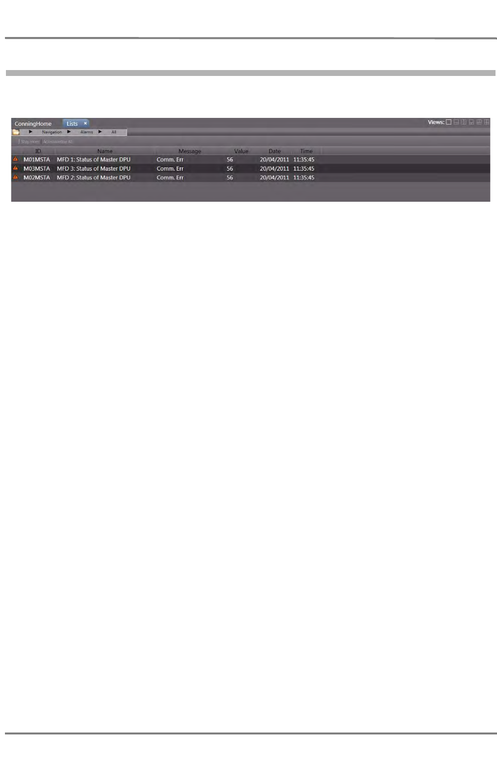
NACOS Platinum
ED 3100 G 140 / 04 (2011-11)
Operating Instructions
D-1 Operating the Conning
D CONNING.fm / 10.11.11
D-14
1.9 The Alarm List on Conning
Fig. D / 9 The Alarm List of Conning
The alarm list shows detailed information about the present alarms. Contents and operation of the alarm
list is the same as on the non-permanent area. See chapter V - 1 on page V-3 for details on the alarm
list.
☞ In contrast to the other display modes on the MFD, on the Conning Display the alarm list covers the
entire application area; the list can not be opened in the non-permanent area in Conning mode.
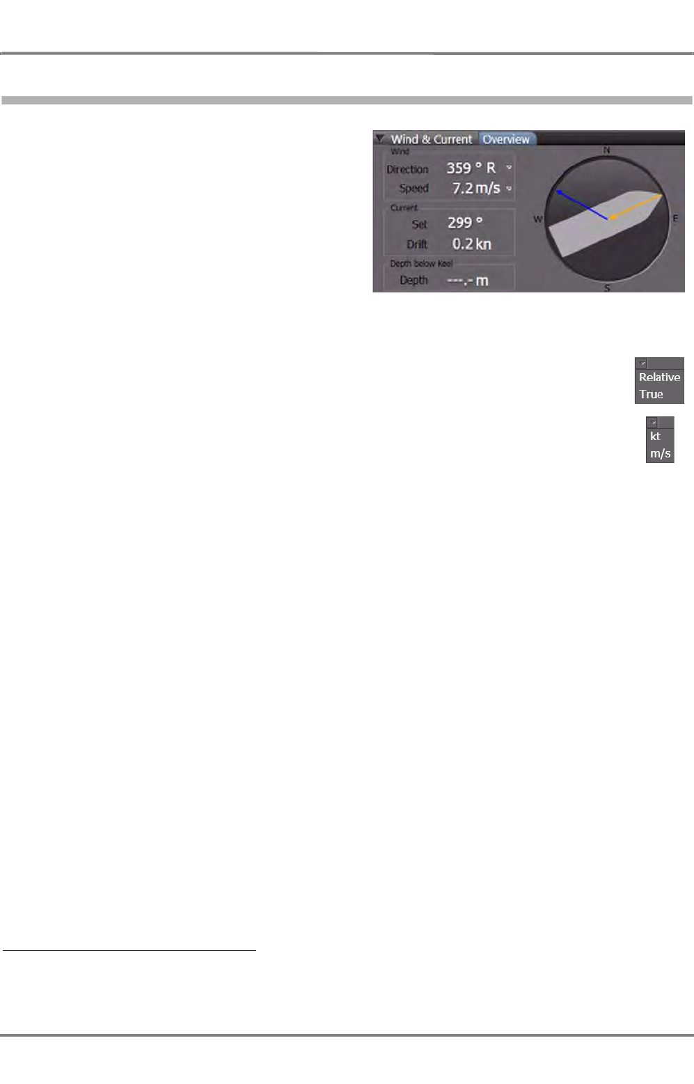
ED 3100 G 140 / 04 (2011-11)
Operating Instructions
D-1 Operating the Conning
D CONNING.fm / 10.11.11 D-15
NACOS Platinum
1.9.1 Wind and Current
This expander contains three groups as a
minimum. 1)
- Wind
Displays the direction and speed of the
actual measured wind, delivered by an
anemometer.
The wind direction can be set as relative or true, the unit for the wind speed can be
set as knots or m/s.
- Current
Displays the direction and speed of the actual measured current. Those values are always true and
in kn. Current data can only be calculated if SOG and STW data are available and valid.
- Depth below tannsducer
Shows the value of the actual measured depth below transducer delivered by the depth sensor. 2)
The depth history is shown in the Depth expander.
1) If available and connected to the system, other environmental data like water and air temperature can be indi-
cated.
2) Depending on the depth sounder connected, also the Depth below Keel can be indicated.
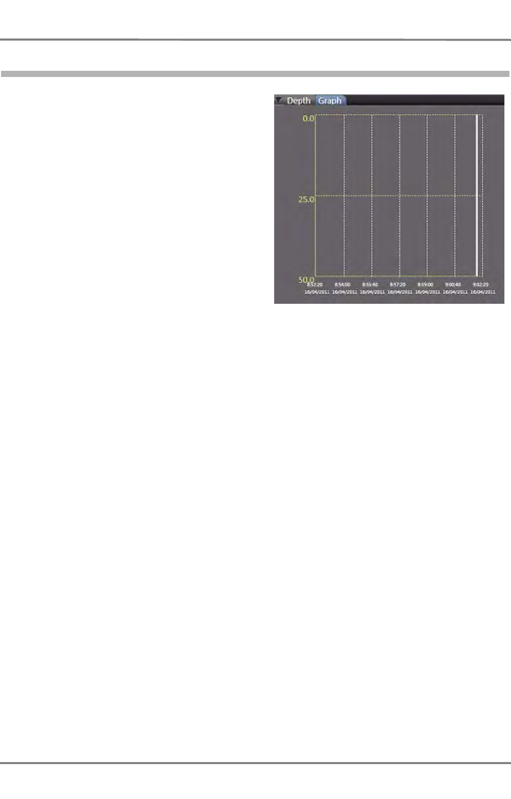
NACOS Platinum
ED 3100 G 140 / 04 (2011-11)
Operating Instructions
D-1 Operating the Conning
D CONNING.fm / 10.11.11
D-16
1.9.2 Depth
The Depth expander shows the run of the
measured waterdepth within the last time
period.
(to be continued)
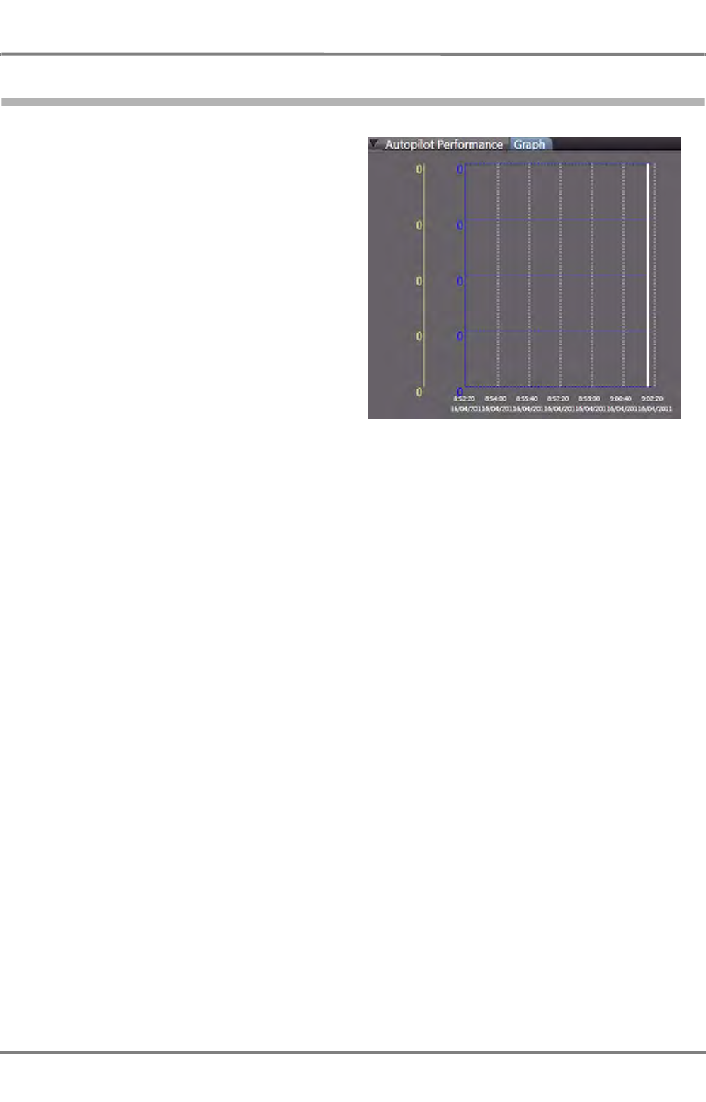
ED 3100 G 140 / 04 (2011-11)
Operating Instructions
D-1 Operating the Conning
D CONNING.fm / 10.11.11 D-17
NACOS Platinum
1.9.3 Autopilot Performance
The Autopilot Performance expander
provides control graphics for the autopilot. The
parameters like time period and scale can be
set by the operator.
(to be continued)

NACOS Platinum
ED 3100 G 140 / 04 (2011-11)
Operating Instructions
D-1 Operating the Conning
D CONNING.fm / 10.11.11
D-18

SENSORS


ED 3100 G 140 / 04 (2011-11)
Operating Instructions
F-1 AIS
F SENSORS.fm / 10.11.11 F-3
NACOS Platinum
1AIS

NACOS Platinum
ED 3100 G 140 / 04 (2011-11)
Operating Instructions
F-1 AIS
F SENSORS.fm / 10.11.11
F-4
1.1 AIS Summarized Briefly
In addition to the ARPA electronics, the Universal Shipborne Automatic Identification System (AIS) auto-
matically provides the ship's nautical officers with important information about nearby vessels or other
relevant objects within VHF range.
The AIS system transmits own ship data cyclically via two defined VHF channels and receives the same
data of the other ships and objects that are equipped with AIS systems.

ED 3100 G 140 / 04 (2011-11)
Operating Instructions
F-1 AIS
F SENSORS.fm / 10.11.11 F-5
NACOS Platinum
1.2 Overview of Functions and Operating Procedures
Targets and Other AIS Objects
With regard to the objects that can be detected by the AIS system and transferred to the radar indicator,
a distinction is drawn between the following:
- AIS targets: ships that are equipped with an AIS system
- SAR aircraft: search-and-rescue aeroplanes or helicopters
- Aids-to-Navigation: navigation marks, e.g. beacons and buoys
- Base stations: Equipment for controlling the AIS system, e.g. as a component of a traffic control
centres.
The AIS targets and SAR aircrafts can be activated and tracked, as well as the radar/ARPA targets. See
chapter 7.1 on page A-56 for details about ARPA and AIS target handling.
All AIS objects can be displayed on the PPI, and in ECDIS mode they can be displayed throughout the
entire chart area. The data of the individual monitored targets can be displayed in detail.
Safety Messages
Via AIS systems, safety messages 1) can be communicated if necessary, which are then passed on by all
receiving AIS systems as a message or an alarm to their display units. The procedures for dealing with
the safety messages received are described in section 3.3.
Monitoring/Setting of the Own Ship Data Transmitted
Most of the information transmitted from your own AIS system is generated automatically by the system.
However, some items of information (e.g. ship's draught, hazardous cargo, destination, ETA) have to be
defined by the operator by inputs to the AIS operating unit.
☞ Because these data are voyage dependent, their input to the AIS unit should be assured by including
them in the nautical check list.
Setting of the communication technique (channel selection, bandwidth, transmission power etc.) usually
takes place fully automatically. In very rare cases, however, manual setting procedures too might be
necessary for the channel management.
The Type of your own AIS System
The interface between an AIS transponder electronics unit and the display/operating unit (here, RADAR-
PILOT or ECDOSPILOT) is standardised. Any type approved class A transponder can be connected to the
Platinum system. All the display related functions as described in the subsequent chapters can be
controlled from the RADARPILOT/ECDISPILOT user interface.
Installation settings like MMSI, GPS antenna location etc. are not standardised, they are set with the
corresponding MKD (minimum keyboard display) which comes along with an AIS transponder system. For
the Platinum AIS transponder system 3410 there is no MKD required. The initial configuration can be
carried out with the Platinum Integration Manager SW Tool.
1) Also called safety related messages in the relevant regulations.
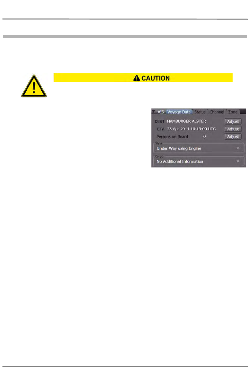
NACOS Platinum
ED 3100 G 140 / 04 (2011-11)
Operating Instructions
F-1 AIS
F SENSORS.fm / 10.11.11
F-6
1.3 Setting the Voyage Data
Most of the data that are sent by the own AIS system for the purpose of target data display on other
ships (own AIS data) are generated automatically by the system (e.g. identification data, position etc.).
However, some items of information (e.g. ship's draught, cargo, destination, ETA) have to be defined by
the operator.
Select Settings > AIS > Voyage Data to enter the tab.
Check and adjust the displayed information as required
for your voyage.
DEST
Destination of this voyage
ETA
Estimated time of arrival at the specified destination
Persons on Board
The number of persons on board.
STATE
Navigational state as specified in the rules. For example "Under Way unsing Engine", "At Anchor" etc.
CARGO
Prescribed information about the cargo as specified in the rules. For example "None", "Hazardous Goods
Class A" etc. The available choice depends on the type of ship set in the basic configuration of the Plat-
inum system. In case the present ship is a passenger vessel, this group would be named Passenger
instead of Cargo.
☞ In the fields State and Cargo it is only possible to choose between specified entries. This is done
in the list which appears after clicking on the field concerned. As long as the cursor is situated on
the field State or Cargo, a small window appears below this field, containing information about the
entry.
The following data must be entered at the beginning of every voyage, and must
(if necessary) be updated during the voyage to ensure correct and up-to-date
information to be sent to other ships.

ED 3100 G 140 / 04 (2011-11)
Operating Instructions
F-1 AIS
F SENSORS.fm / 10.11.11 F-7
NACOS Platinum
SOLAS Chapter VII - Carriage of dangerous goods
requires among other things the declaration of hazardous substances contained in the
cargo.
MAPOL Annex II - Regulations for the Control of Pollution by Noxious Liquid
Substances in Bulk
defines the following categories for hazardous liquid substances:
Category A - Noxious liquid substances which if discharged into the sea from tank cleaning or
deballasting operations would present a major hazard to either marine resources or human health
or cause serious harm to amenities or other legitimate uses of the sea and therefore justify the appli-
cation if stringent anti-pollution measures. Examples are acetone cyanohydrin, carbon disulphide,
cresols, naphtalene and tetraethyl lead.
Category B - Noxious liquid substances which if discharged into the sea from tank cleaning or
deballasting operations would present a hazard to either marine resources or human health or cause
harm to amenities or other legitimate uses of the sea and therefore justify the application if special
anti-pollution measures. Examples are acrylonitrile, carbon tetrachloride, ethylene dichloride and
phenol.
Category C - Noxious liquid substances which if discharged into the sea from tank cleaning or
deballasting operations would present a minor hazard to either marine resources or human health
or cause minor harm to amenities or other legitimate uses of the sea and therefore require special
operational conditions. Examples are benzene, styrene, toluene and xylene.
Category D - Noxious liquid substances which if discharged into the sea from tank cleaning or
deballasting operations would present a recognizable hazard to either marine resources or human
health or cause minimal harm to amenities or other legitimate uses of the sea and therefore require
some attention in operational conditions. Examples are acetone, phosporic acid and tallow.
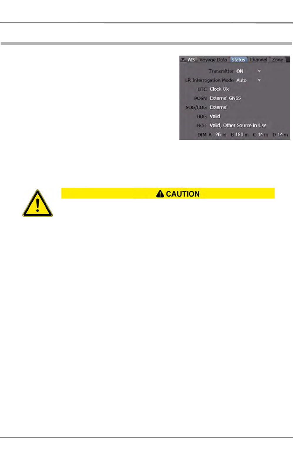
NACOS Platinum
ED 3100 G 140 / 04 (2011-11)
Operating Instructions
F-1 AIS
F SENSORS.fm / 10.11.11
F-8
1.4 Setting the transmitter / Transmitter Status
In this tab, the status of the AIS transponder and addi-
tional information are shown.
It is possible to prevent the AIS from transmitting
completely.
The Long-Range Interrogation Mode can be set
here.
Transmitter
Select On or Off.
☞ The status Transmitter On/Off is stored with date and time and can also be called up after an
accident at sea.
Long-Range Interrogation Mode
The AIS system can also be interrogated about own ship data (e.g. own AIS data) by another system,
e.g. a SatCom system. Because this interrogation can take place over longer distances than the VHF
range, it is called "long-range interrogation".
The interrogating station specifies which data are requested. The reaction of the AIS electronics unit can
be set by means of the Long-Range Interrogation Mode.
- ON: The interrogation(s) are replied as specified
- OFF: No alarm appears, no reply is sent
- MANUAL: In the case of an interrogation, the AIS Interrogation alarm appears. By acknowledge-
ment, the AIS Interrogation dialog appears. The reply is sent with the Reply button or is instead
prevented with the Close button.
- AUTO: In the case of an interrogation, the reply is sent automatically. For the purpose of informa-
tion, the AIS Interrogation alarm appears; it should be acknowledged in the usual way.
The transmitter should not be switched off except in justified exceptional cases,
because when it is switched off, own ship can no longer be detected as a target
by other ships and cannot participate in the communication between ships,
equipped with AIS.

ED 3100 G 140 / 04 (2011-11)
Operating Instructions
F-1 AIS
F SENSORS.fm / 10.11.11 F-9
NACOS Platinum
Status Information
The fields UTC to DIM D contain status information about own navigational sensors whose data are
transmitted as own AIS data and the reference point of the position reported.
UTC
The status of the internal clock of the transmitter. (Clock Ok or Clock Lost)
POSN
Depending on the connected systems, several different indications are possible.
- External GNSS.... means that the GPS receiver connected externally to the AIS electronics unit is
being used for this purpose. DGNSS is also possible, if differential mode is used by the position
fixing device.
- Internal.... means that the internal GPS receiver in the AIS electronics unit is being used for this
purpose.
SOG/COG
Information about the source of the transmitted SOG/COG data. (External or Internal)
HDG
Status of the heading data (Valid or Invalid)
ROT
Indicated as Valid or Invalid,
- Other source means that an approved ROT sensor is not being used, and so only the direction but
not the rate of the heading change is transmitted. In this case, only the direction of turn (port/star-
board manoeuvre) can be displayed on the receiving system.
The fields DIM A to DIM D show the distance of the reference point to bow, stern, port and starboard
side in meters. The reported position is referenced against this point. Further on the size of the own ship
can be derived from this information.
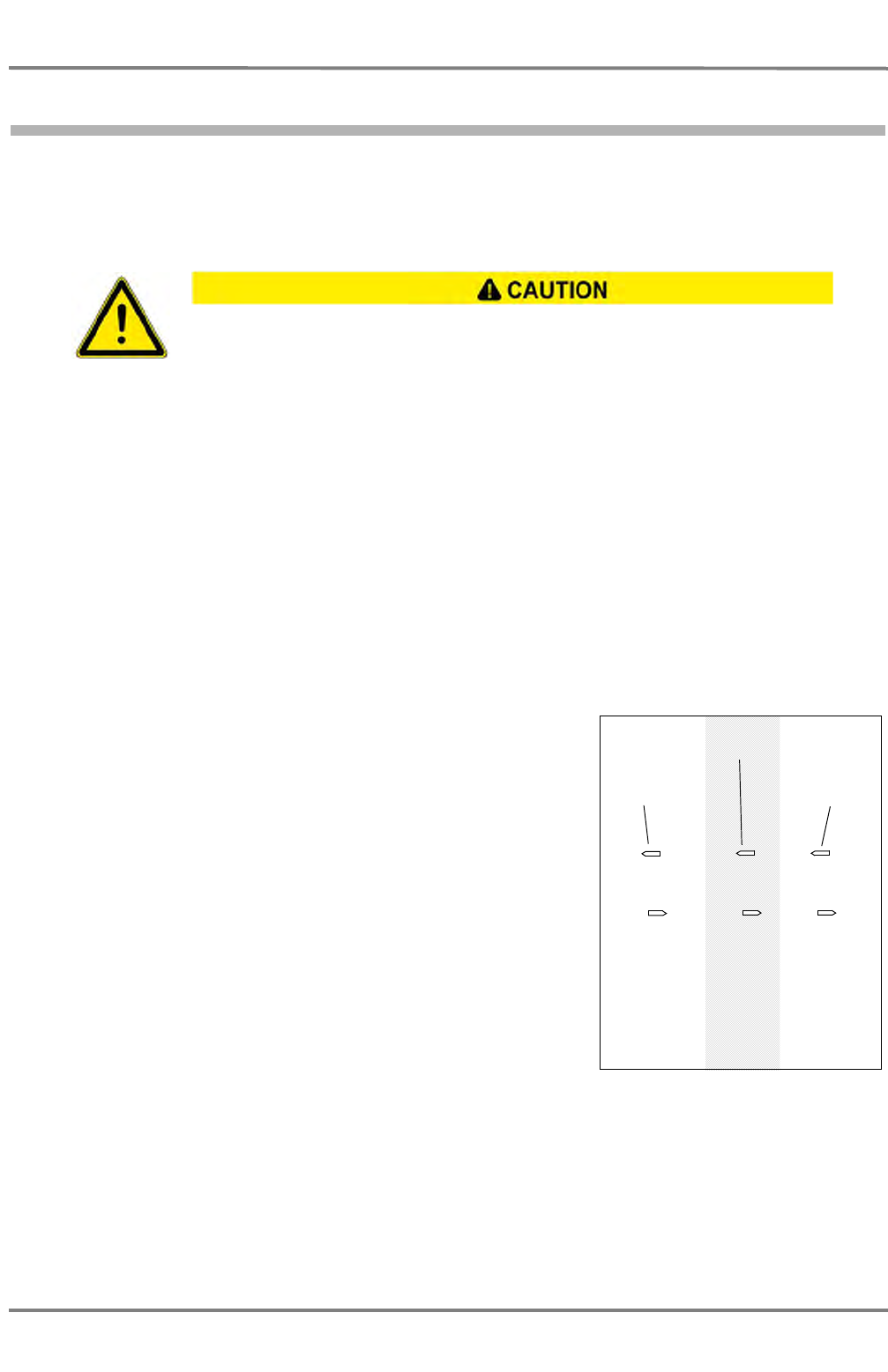
NACOS Platinum
ED 3100 G 140 / 04 (2011-11)
Operating Instructions
F-1 AIS
F SENSORS.fm / 10.11.11
F-10
1.5 Channel Management
The AIS system cannot function unless all AIS systems communicate on the same VHF channels and
unless the communication bandwidth and the transmission level are correctly set. The settings needed
for this are normally made automatically as described in the following.
VHF channels 2087 (161.975 MHz) and 2088 (162.025 MHz) are used worldwide for the two AIS chan-
nels.
As default values, AIS channel A uses the VHF channel 2087, the AIS channel B uses the VHF channel
2088, and for both channels, the bandwidth setting is Auto, and transmission is performed with power
level High. Every mobile AIS station operates on these two channels. A mobile AIS station is thus
capable of receiving two messages, from two different stations concurrently, provided that it does not
transmit at the same time.
In particular geographical regions or situations, i.e. due to local RF interference, it is necessary to deviate
from these settings. The necessary values are received via the AIS channels from a local VTS centre,
harbour administration etc.
These data also contain the information about the region in which these settings are to be used,
including the transition zone surrounding that region.
The switch-over is performed automatically when the ship is
located in the transition zone. This is done in the following steps:
- As soon as the ship reaches the boundaries of the transition
zone, one AIS channel is set to the different VHF settings
(with the other AIS channel remaining unchanged) and the
alarm Channel management changed is shown. As a result,
the targets situated inside and on either side of the transition
zone are now seen and the ship is also seen by these targets;
see the diagram.
- On leaving the transition zone, the second AIS channel is also
switched over to the different VHF settings.
The general effect is that a ship which is not located in the transi-
tion zone does not see any targets located behind the transition
zone.
The transponder is capable of managing 8 different zones auto-
matically. Each zone is described by the South-West and North-
East corner of a rectangle.
Each zone may have different channel management settings. Administrations may set your AIS by special
messages automatically to a certain locally required setting. You can check these settings, which are
stored in your AIS, by opening the tabs for channel and zone. You can toggle from one to the next
settings by using the Next button. Although manual setting is also available, it is strongly recommended
not to use the manual function. This should only be done on special advice of a local administration i.e.
by radio or other means if the automatic function is not available from coastside. There is a severe risk,
It is also possible to make a setting manually, but this should only be done in
exceptional cases and following the advice of a local administration received by
radio, publications, etc. and only after having informed the ship's command
personnel accordingly. For manual setting, see chapter "Displaying the Channel
Data Set" on page F-11.
C
AE
D
BF
Transition
zone
Region with
different VHF
settings
Sees
Sees
B, C, D
A, B, D, E, F
Sees
C, D, F
Area with
default VHF
settings
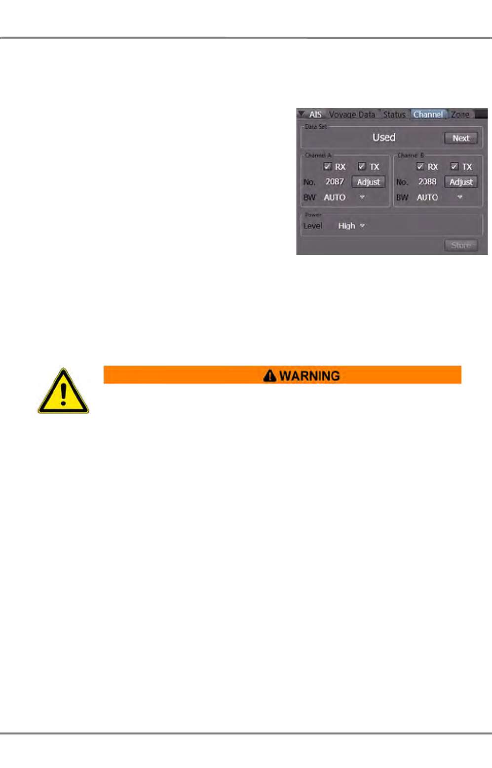
ED 3100 G 140 / 04 (2011-11)
Operating Instructions
F-1 AIS
F SENSORS.fm / 10.11.11 F-11
NACOS Platinum
that due to manual setting the own ship is no longer visible to other ships as an AIS target and that you
will not see any other AIS targets on your system. Normally, the default setting should be on channels
2087 and 2088 and should have no position entered. Bandwidth is on Auto, Power is on High.
Displaying the Channel Data Set
- Used: The data currently being used by the AIS
electronics unit
- Not Used: Data are currently not being used by
the AIS electronics unit.
- Edited: The displayed data have been altered
manually but have not yet been stored.
By clicking on Next, the next data set (channels,
bandwidth, mode, power, geographical region and
transition zone) can be displayed.
Channel A and Channel B
Switch on the transmitter (TX) and/or the receiver (RX) as required by checking the box accordingly. For
special purposes and by advice of an administration select the radio channel and bandwidth.
BW - Bandwidth
The Bandwidth can be set to Auto or 12,5 kHz.
Power
Can be set to High or Low. During the loading and unloading of tankers, the transmission power of the
AIS transmitter must be reduced for safety reasons. At anchor and during mooring it might be necessary
as well.
Finally klick on the Store button to store the set data.
Changes on the settings of the VHF channels, bandwidth or geographical data in
use (by entering a data set) shall be done by authorised and well skilled
personnel only. Each change may have a serious influence on the VHF communi-
cation between AIS systems.
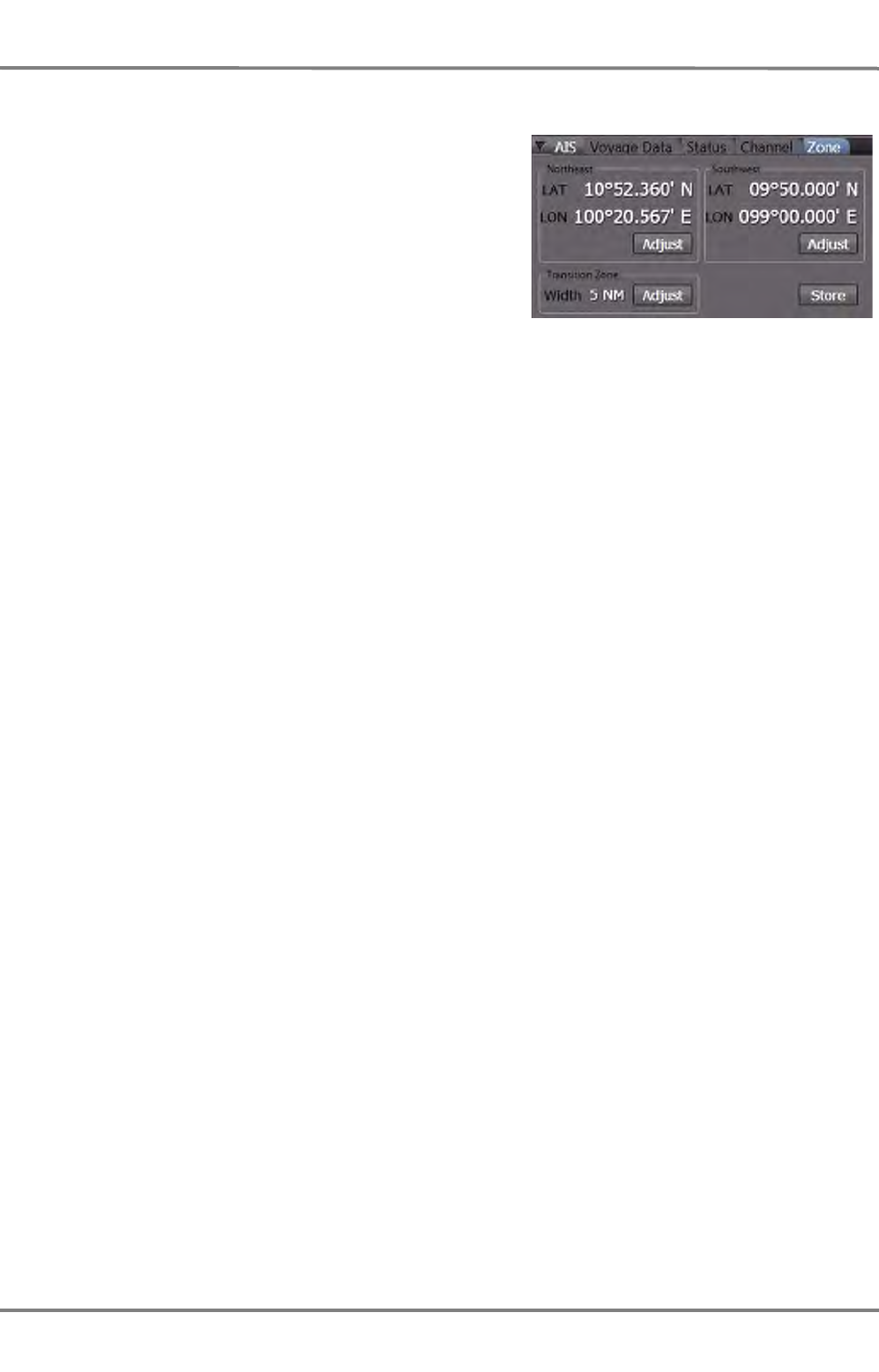
NACOS Platinum
ED 3100 G 140 / 04 (2011-11)
Operating Instructions
F-1 AIS
F SENSORS.fm / 10.11.11
F-12
Displaying the Zone Data
The Zone Tab shows the zone related information of
the eight data sets for channel and zone which are
stored in the AIS transponder.
Select Settings > AIS > Zone to enter the tab. The
first two groups for Northeast and Southwest show the
diagonal corner points of the zone. The next group
shows the transition zone as described in the introduc-
tion to this chapter. The default values for the corner
position are empty fields. Any entries should only be
made on advice of an administration as explained
before. Any values might also have been set automat-
ically by received AIS command messages from a local VTS centre. They will become active if the own
vessel reaches the defined zone.
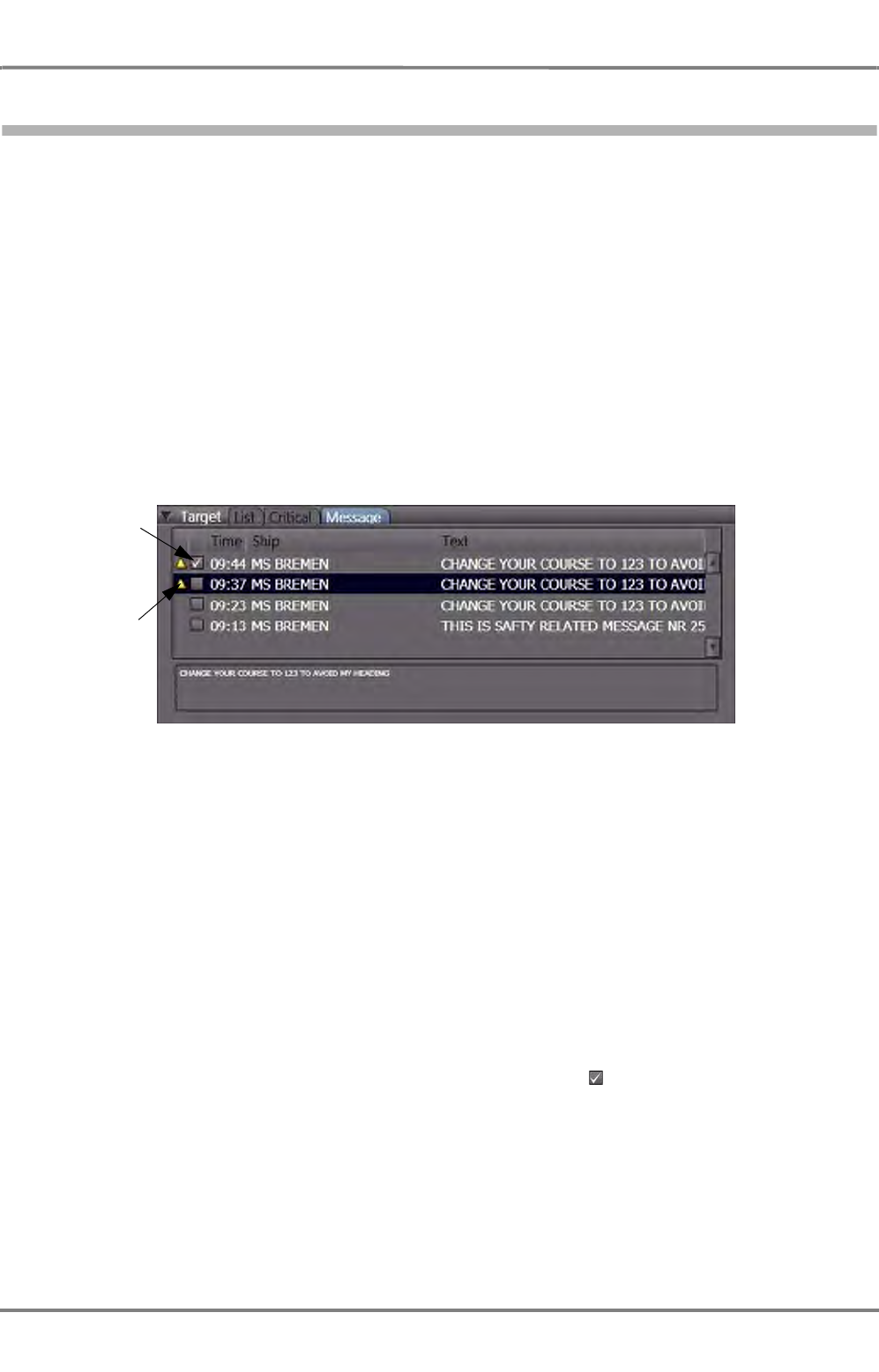
ED 3100 G 140 / 04 (2011-11)
Operating Instructions
F-1 AIS
F SENSORS.fm / 10.11.11 F-13
NACOS Platinum
1.6 Receiving AIS Messages
The AIS unit can receive safety related messages from other ships. These messages are transmitted to
the system and stored in the MFD until up to a maximum number of 50 for a certain time period.
If the maximum number of messages is reached, the oldest messages will be deleted automatically.
New messages generate a warning in the alarm system in order to alert the operator of viewing the
message text in the target related message list.
New Safety Message
When the AIS electronics unit receives a safety message, this is sent to the connected interface and the
New AIS Safety Message warning appears in the alarm list of the MFD. By acknowledgement the
warning disappears from the list.
The operator must open the safety message list via Tools > Target > Message in order to have access
to all received and temporarily stored messages.
Fig. F / 1 AIS Message List after receiving a new safety message
☞ The list is sorted according to the receive time of the messages; the latest (newest) entry is shown
at the top of the list. The sorting sequence of the list cannot be changed.
☞ Any message from the same source with the same text as already received will not be stored again,
but its time marking in the list will be updated. In this way it will show up in the first line again.
☞ The receive time, the identification data of the transmitting AIS object and the start of the text are
shown above the message. The complete text is enclosed in the frame below the list of messages.
☞ By a click into a line of the list you can select the message to be shown in the text window.
☞ In the first column of the list a yellow alarm icon is shown if the related message alarm is not yet
acknowledged. Additionally all new (unread) messages have a marker in the second column until
the message has been selected and shown in the text window.
Message not yet
acknowledged
Message not yet
read

NACOS Platinum
ED 3100 G 140 / 04 (2011-11)
Operating Instructions
F-1 AIS
F SENSORS.fm / 10.11.11
F-14
Operating in the List
The width of the columns in the list can be modified if required, but none of the columns can be made
completely invisible. If the lines get longer than the width of the window, a horizontal slider will be shown
which can be used to move to invisible parts of the window.
A vertical slider is shown if the number of list entries does not fit into the window. Scroll to the top of
the list to see the newest (last received) message.

OPTIONAL APPLICATIONS


MAINTENANCE

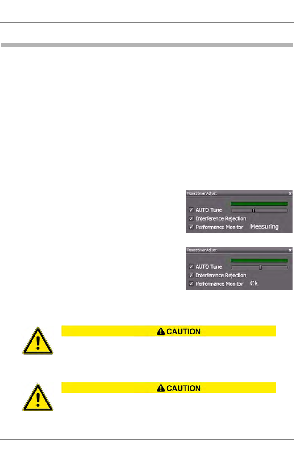
ED 3100 G 140 / 04 (2011-11)
Operating Instructions
H-1 Performance Monitor
H MAINTENANCE.fm / 10.11.11 H-3
NACOS Platinum
1 Performance Monitor
Note:
The Performance Monitor is only present in systems with Radar Platinum.
Background
The performance monitor provides the operator with a simple go/no-go tool to check the transmitter
performance as well as the receiver sensitivity in one step. It comprises a small test oscillator and a
microwave diode with amplifier. Both modules are installed under a hole in the gearbox. The hole is
hermetically sealed with a transparent plastic cover.
The diode receives the radar pulse which is transmitted by the magnetron via waveguide and scanner
into the air. The received signal is amplified and gives an indication about the function of the complete
transmitter path.
The test oscillator transmits a pulse at about 1 msec after the main pulse. This pulse lies outside the
display space and is not visible in the radar image. It simulates a target being far away. This signal is
picked up by the scanner and gives an indication of the proper function of the complete receiving path.
Test
The selected transceiver´s performance can only be
tested by the MFD which is selected as Master for it. If
Master is not selected, the Adjust control will be insen-
sitive. Click the Transceiver Adjust control, the corre-
sponding submenu will open. Check the control for
Performance Monitor. Wait for a minute, the result
will be shown as follows:
- If the sum of both indications from TX and RX path
together is ok, the test is shown with an Ok in the
Transceiver Adjust box.
- If the sum of both indications from TX and RX path
is degraded, the test is shown with a Critical result.
- If the sum of both indications from TX and RX path
is degraded by more than 10 dB, the test is shown
with a Most Critical result.
Switch off the performance monitor by closing the Transmitter Adjust box.
During the test, the radar is fixed to 12 nm and cannot be switched to another range. Do
not start the performance test with a cold transceiver, wait 30 min after switching-on. The
test result could be disturbed by heavy snowfall or rain, shading the hole in the gearbox.
The test result could also be disturbed by other transceivers on-board. They should be
switched off.
If "Most Critical" is shown as the result, this means that the performance quality
of the radar system is no longer adequate for safe radar operation. Request
service!

NACOS Platinum
ED 3100 G 140 / 04 (2011-11)
Operating Instructions
H-1 Performance Monitor
H MAINTENANCE.fm / 10.11.11
H-4
☞ Not only the magnetron that is being checked with this test but also the toothed belts of the
antenna gearing are expendable parts. Therefore, if the test shows that the magnetron has reached
the end of its useful life, the toothed belts shall be checked and must be exchanged as well during
the necessary service work.

ED 3100 G 140 / 04 (2011-11)
Operating Instructions
H-2 Data Maintenance of the Electronic Charts
H MAINTENANCE.fm / 10.11.11 H-5
NACOS Platinum
2 Data Maintenance of the Electronic Charts
2.1 General
The electronic charts for your NACOS Platinum System are stored separately on each MFD (workstation).
They have to be updated in regular intervals.
After initial installation from the base media the charts are updated typically in a weekly schedule from
the update media. During the update process the already installed charts are checked and it might be
necessary to insert the base media again if requested by the update application during the update
process
The update can be carried out for each MFD separately by using update media like CD ROM, USB-Stick,
or portable USB drive. The procedures will take some time, because the chart cells are processed on the
MFD, in case of ENC charts they are also decrypted and converted into an internal file format. This
improves the chart presentation speed during later ECDIS operation.
For practical reasons it is recommended to perform the time-consuming update from media on the ECDIS
planning system. Once this MFD has been updated, the other MFD’s in a network can be updated by a
simple and faster network action.
☞ The initial installation can take several hours. Even an update may require a considerable length of
time. Therefore, perform this task in good time before the start of the voyage.
☞ The chart maintenance work must be carried out so that the databases of all MFD’s always have
the same status. This is ensured if the notes given here are observed and the sequences described
are followed.
- An easily determined indication of unequal states of the databases of the MFD’s is when the
numbers of cells/ charts displayed for one MFD is different from the others.
- An update of a chart cell can only be performed if the base information for this cell has been
installed before. Also the update sequence must not be interrupted. If one update has been missed
in the past it is not possible to add a new update. In that case carry out the base update again.
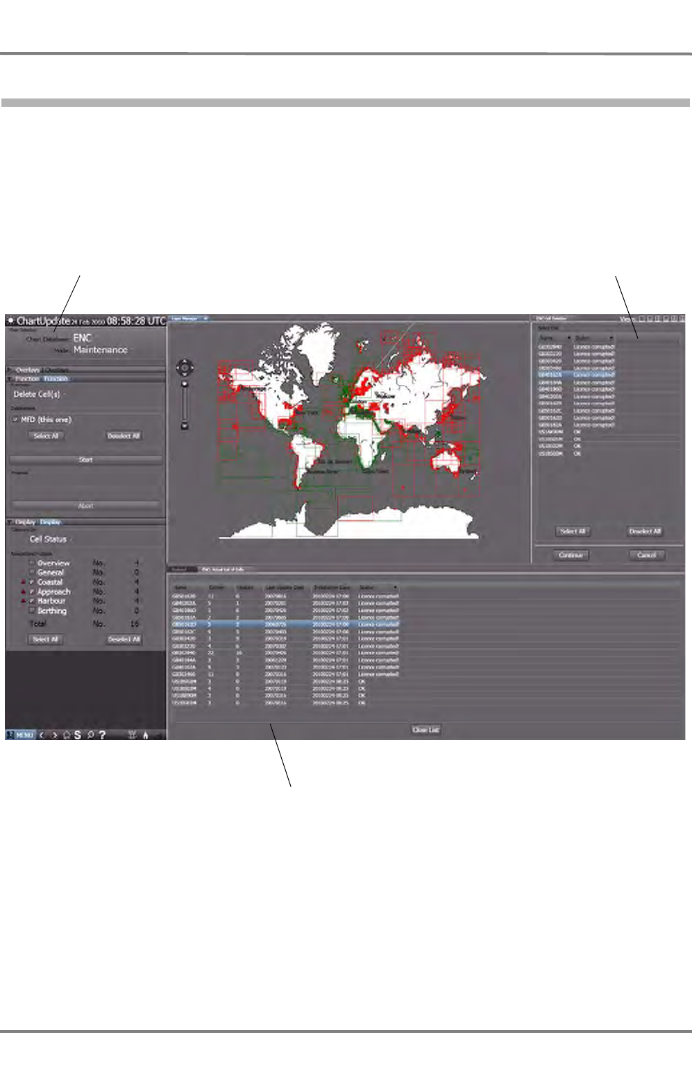
NACOS Platinum
ED 3100 G 140 / 04 (2011-11)
Operating Instructions
H-2 Data Maintenance of the Electronic Charts
H MAINTENANCE.fm / 10.11.11
H-6
2.2 Starting Chart Maintenance
Navigate to the Super Home menu and click on Maintenance > Nautical Charts.
As a result, the world chart together with a main selection sidebar, a protocol window, and an action
area appears.
If the chart maintenance is started for the first time after power-on of the electronics unit, the database
will be checked automatically. Any errors will be displayed in the protocol window underneath the world
map.
Background operation
To use the MFD for other purposes while prolonged maintenance sequences are running automatically,
just navigate to the main menu and choose the appropriate application.
☞ As soon as the Chart Maintenance program running in the background needs an operator action, a
message is shown.
Main Selection
Protocol Window
Action area
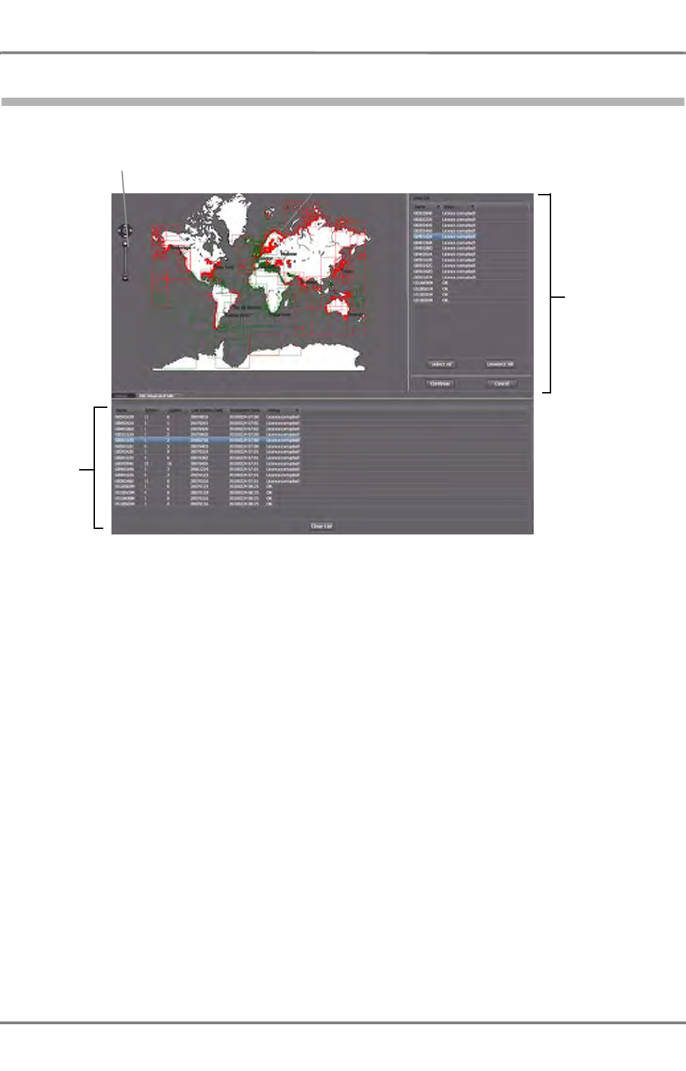
ED 3100 G 140 / 04 (2011-11)
Operating Instructions
H-2 Data Maintenance of the Electronic Charts
H MAINTENANCE.fm / 10.11.11 H-7
NACOS Platinum
2.3 Chart Maintenance Application Area
This screen shows an overview of the installed charts and their states. Depending on the settings of the
Mode in Main Selection, the cells appear with a coloured border. See section 2.8 for details.
The Pan and Zoom control can be used in the same way as described in see chapter A - 4.1 on page
A-34.
The Actual List of Cells (or permits) shows detailed information about the kind of cells or permits
selected in the Display expander. It can be chosen how the data are to be sorted (ascending/
descending) according to the details. Click the column header of the appropriate detail to sort according
to it.
If Mode is set to Maintenance and Function is set to Delete Cell(s)/Permit(s), the list of cells /
permits to be deleted is opened in the top right corner.
Pan and
Zoom Control
Information
area:
Protocol and/
or actual list
of cells/
permits
Action area:
List of cells/
permits to be
deleted
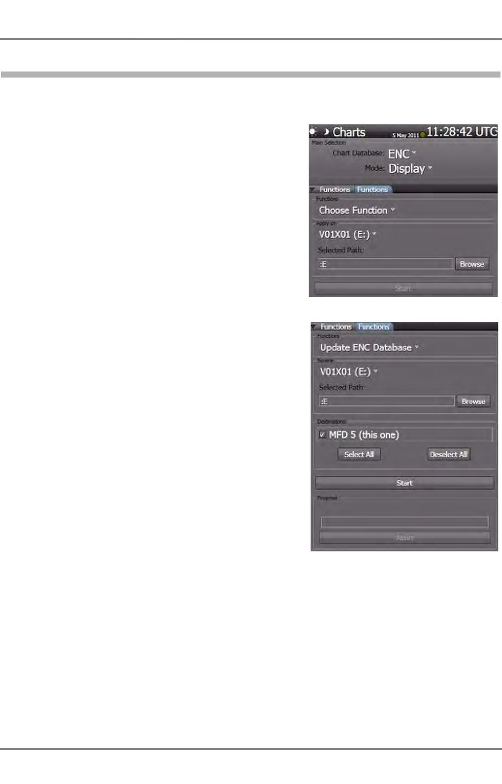
NACOS Platinum
ED 3100 G 140 / 04 (2011-11)
Operating Instructions
H-2 Data Maintenance of the Electronic Charts
H MAINTENANCE.fm / 10.11.11
H-8
2.4 Update of Charts from Media
Insert your latest update media, either CD ROM or USB stick or portable USB drive. It may be either a
base update (all chart cells) or a weekly update (a few chart cells only).
Open the Functions menu from the side bar.
Check Chart database, set to ENC or ARCS depending
on the charts which you want to update.
Select Mode, the default setting is Display, set to
Update. Once the mode has been set to Update the
Functions menu is modified with subgroups for Source
and Destination as shown in the next screenshot.
Select the Functions, the default setting is Choose
Function, set to Update ENC Database or to Update
ARCS Database.
Select the Source for the update. It could be either a CD
ROM, a removable USB Stick, or USB drive. In the
example here a CD ROM has been selected. If the media
has a label, it is shown, here it is V01X01 (another work-
station (MFD) may be selected as well, but only, if on
that workstation the update has already been
performed).
Check the Selected Path. Platinum will display any
chart data laying on top of the directory automatically. If
nothing is found, open Browse to search manually for
the subdirectory with the chart data.
The Destinations entry is set per default to the present
workstation (this one), where the update is carried out.
No other selection is possible and required.
Press Start to activate the update if it is not started
automatically.
A protocol of the update is shown in the bottom of the
main application area. Message windows as described on
the next page will appear in the overview chart to inform
about the progress and any obstacles.
During the update you will be asked to insert one after the other the base media (i.e. ARCS RC 1 to RC
11), and after that the update media again. Just follow the instructions given on the screen.
Some of the above steps like selecting the Update Mode will be started automatically if an appropriate
update CD is inserted. Just follow the instructions on the screen.
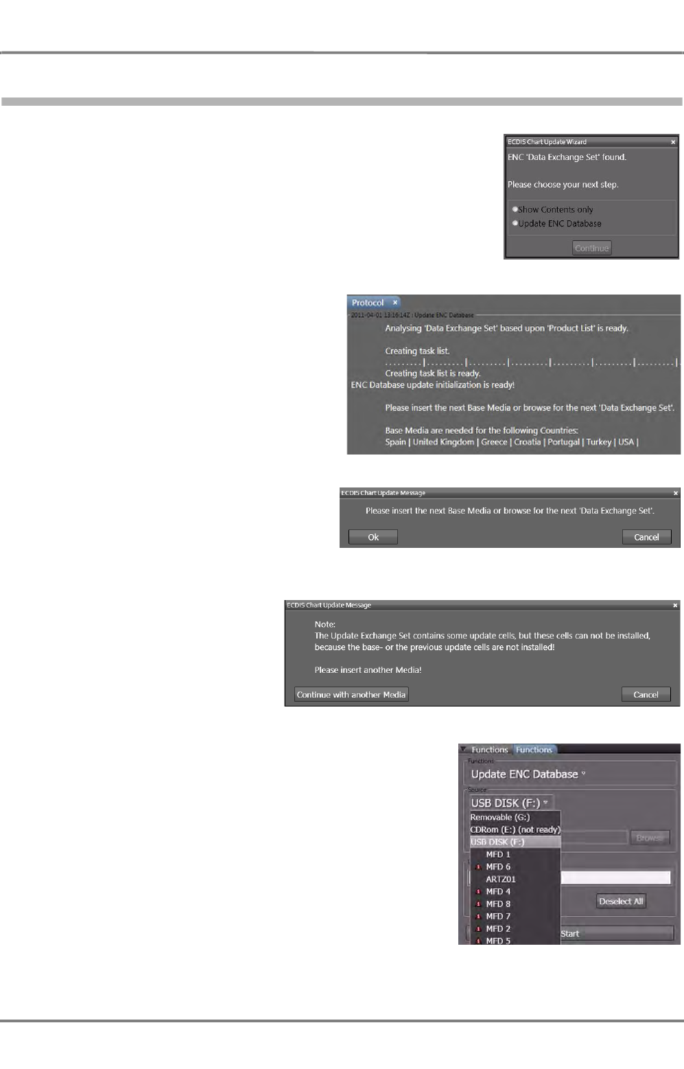
ED 3100 G 140 / 04 (2011-11)
Operating Instructions
H-2 Data Maintenance of the Electronic Charts
H MAINTENANCE.fm / 10.11.11 H-9
NACOS Platinum
2.5 Messages during Chart Update
ENC or ARCS Data Exchange Set found
If an update has been performed before and the media is inserted
again, it is not started automatically but the Chart Update Wizard
appears. It informs the user that chart data are available on the
media. Select either Show Contents or Update and the procedure
is continued as before.
Base Media are Needed
If the weekly update comprises information
for cells, which have not been installed
before on your MFD, the base media for
those countries, which are listed in the
bottom of the protocol window have to be
inserted. In case of ARCS you are asked to
insert one of the base media CDs (RC1 to
RC11).
Insert Next Base Media
During the update process for the base
media this message will appear if another
base media (CD or other) with the
remaining base cells has to be inserted .
Update Cells can not be
Installed
If an update media is inserted and
base cells are still missing or have
not been updated to the previous
update, a warning is given. Load
the corresponding base cells.
Update another MFD in the Network
Enter the maintenance menu on that MFD (workstation), which
shall be updated. Follow the instructions as given before.
Select as a source the workstation, which has been updated
already from an update media. Start the procedure by clicking
Start.
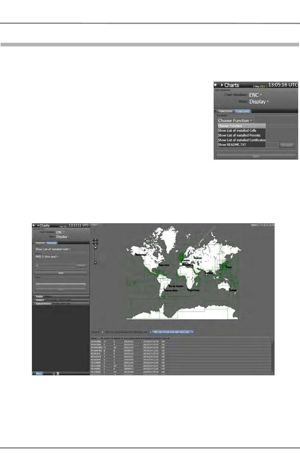
NACOS Platinum
ED 3100 G 140 / 04 (2011-11)
Operating Instructions
H-2 Data Maintenance of the Electronic Charts
H MAINTENANCE.fm / 10.11.11
H-10
2.6 Display Charts which are on a Media or a MFD (workstation)
Insert your media, either CD ROM or USB stick or portable USB drive as shown under Update of Charts
from Media. If your charts to be examined are already stored on the internal drive of your MFD or
another MFD, just skip this step and continue.
Open the Functions menu from the side bar.
Verify that Chart database is set to the correct chart type, ENC or
ARCS.
Verify that Mode is set to its default setting (Display), just leave it
to Display.
Select Functions, the default setting is Choose Function, set to
one of the shown options.
Select Apply on to choose the drive (this MFD, another
connected MFD, CD drive, USB stick, etc.) where your chart data
to be examined are stored.
Check the Selected Path. Platinum will display any chart data laying on top of the directory automati-
cally. If nothing is found, open Browse to search manually for the subdirectory with the chart data.
Click on Start to confirm the settings and list up the cells or permits in a new tab of the protocol window.
At the same time the corresponding cells are marked with green squares in the world chart. Depending
on your selection the installed cells or the installed permits will be shown in the list.
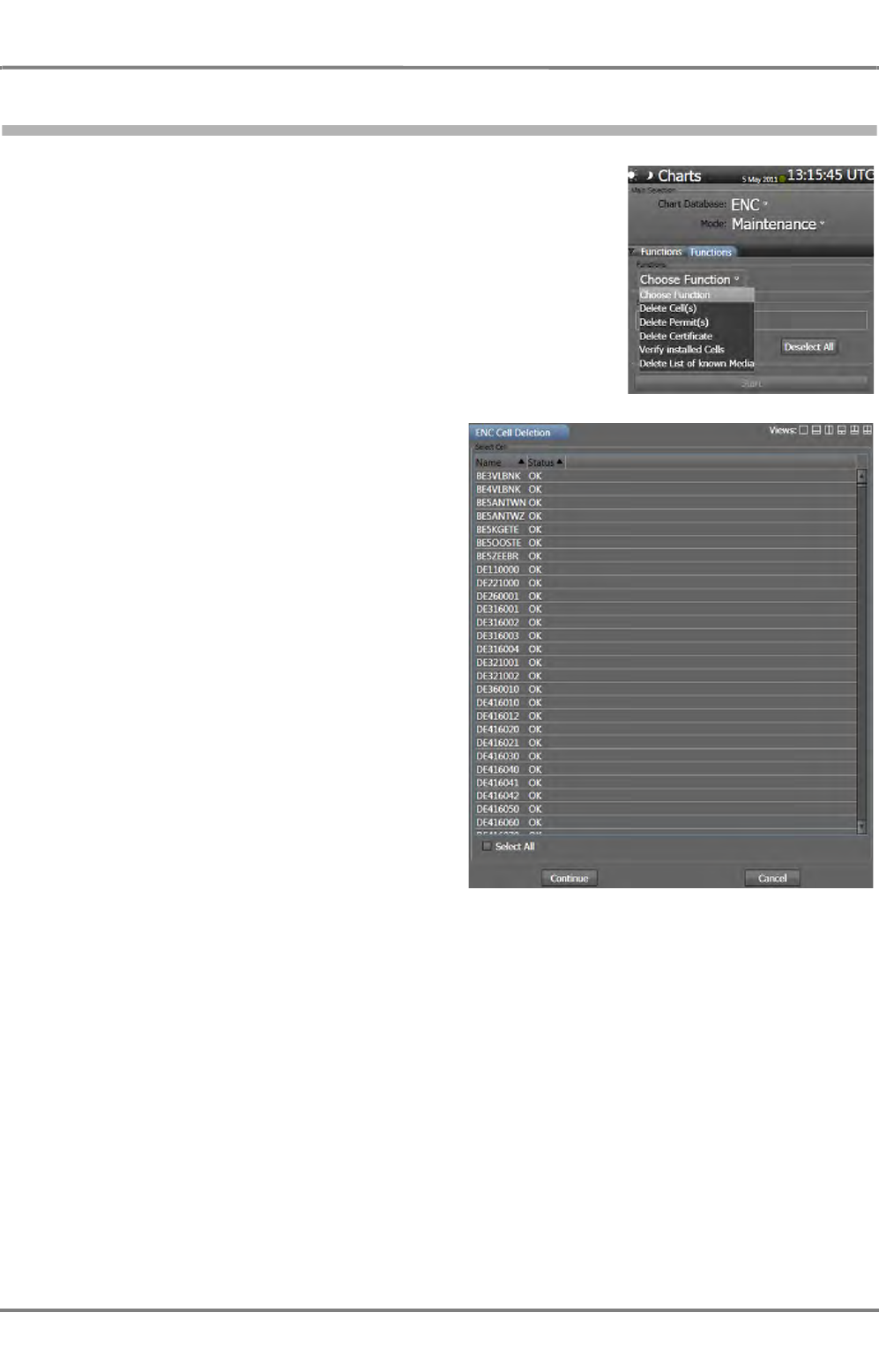
ED 3100 G 140 / 04 (2011-11)
Operating Instructions
H-2 Data Maintenance of the Electronic Charts
H MAINTENANCE.fm / 10.11.11 H-11
NACOS Platinum
2.7 Maintenance of Charts on your MFD (workstation)
Open the Functions menu from the side bar.
Verify that Chart Database is set to the correct chart type, ENC or
ARCS.
Set Mode, to Maintenance.
Select Functions, the default setting is Choose Function, set to
one of the shown options.
Destination is set per default to the harddisc of your MFD. It can
not be changed. Maintenance can only be performed for this MFD.
Click Start to activate the maintenance proce-
dure. Depending on your selection the cells,
permits, or certificates are listed on the right
top side of the screen and can be deleted indi-
vidually. It is recommended to delete all those
cells, permits, and certificates which have
been expired or are no longer valid.
Further-on the installed cells can be verified.
The result is displayed in the protocol window.
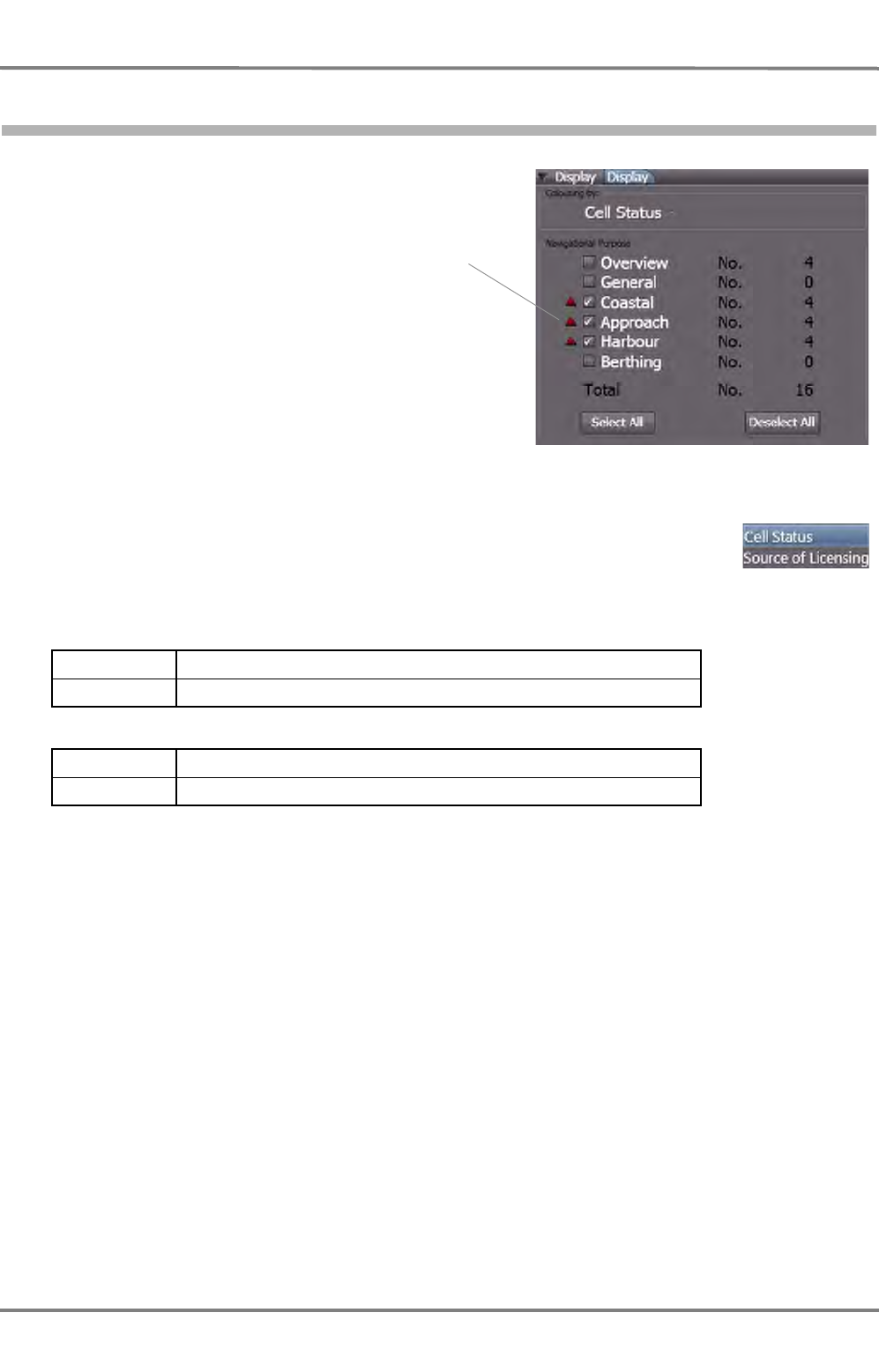
NACOS Platinum
ED 3100 G 140 / 04 (2011-11)
Operating Instructions
H-2 Data Maintenance of the Electronic Charts
H MAINTENANCE.fm / 10.11.11
H-12
2.8 Display Expander
The display expander is used to set up the
display of the cells and for information about
the number of installed cells.
If an alarm indicator, a small triangle, is
displayed in front of one of the chart types,
an eror has occurred when the appropriate
data have been checked.
It is a good idea to do this for each kind of
navigational purpose charts one by one in
order to decrease the amount of cells to be
checked.
Colouring by
The cells displayed in the overview are shown with a coloured frame. Depending on
the settings in Colouring by, the cell status or the licensing status are concerned
for the choice of the colour.
Cell Status
Source of Licensing
Red An error has occurred while the data have been checked
Green Chart is okay
Yellow The license of the chart has been checked unsuccesfully
Green Chart is okay
Alarm
indications
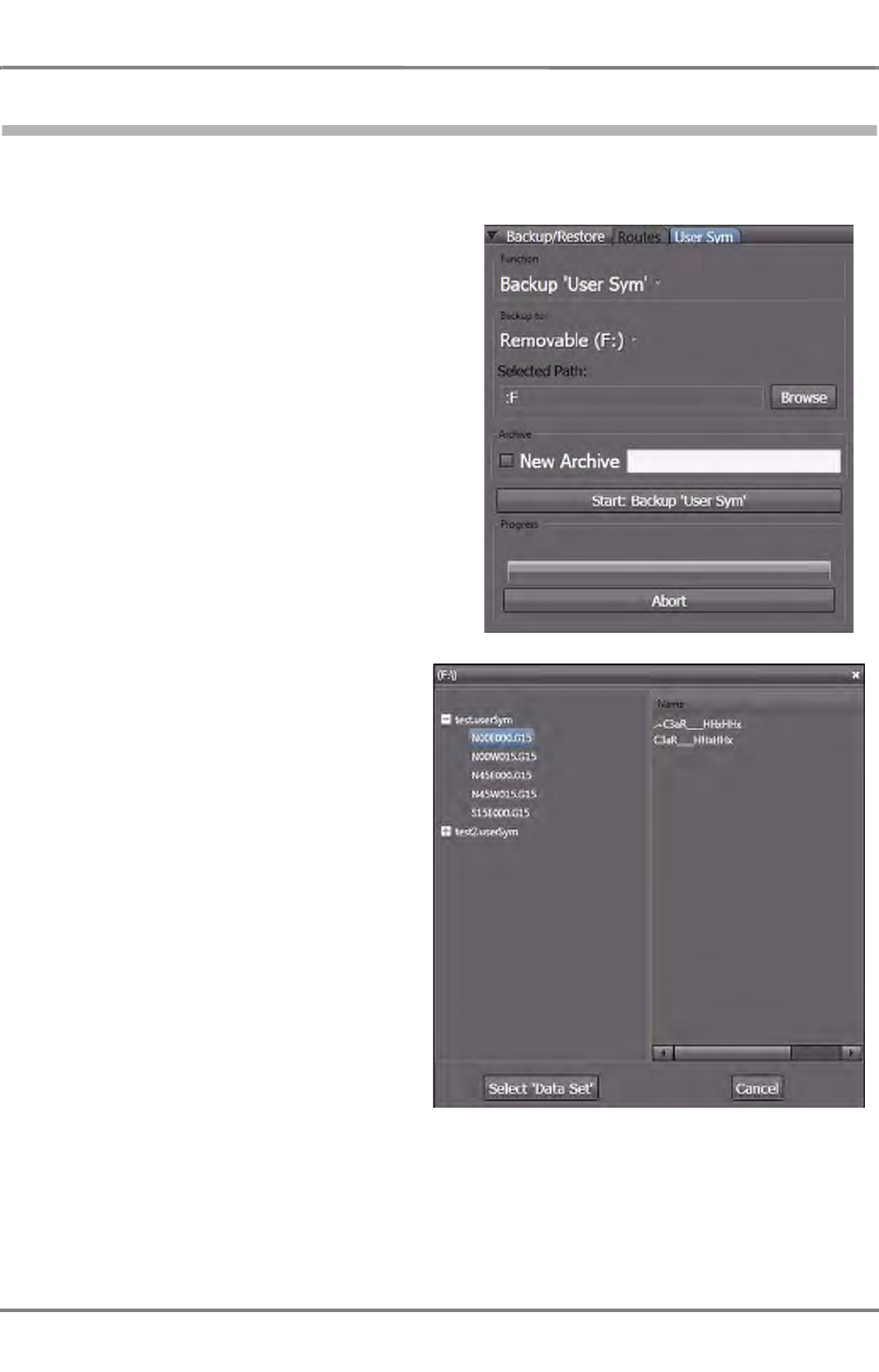
ED 3100 G 140 / 04 (2011-11)
Operating Instructions
H-2 Data Maintenance of the Electronic Charts
H MAINTENANCE.fm / 10.11.11 H-13
NACOS Platinum
2.9 Backup/Restore of Map Data
The user-defined Routes and also the User Symbols can be saved to devices like CD-ROM or USB
memory sticks. This makes it possible to transfer those data to other systems or replacement modules.
In order to backup routes or user defined
symbols, follow these instructions:
1. In the tabs of the expander, chose
whether to backup Routes or User
Sym
2. In the Function group, select whether
the data are to be backed up or
restored. (The following example refers
to the backup-function. The restore-
function works similar, but the Archive
group is then inactive.
3. Under Backup to: choose the device
which is to be used as backup/restore
media.
4. Select the path and, if an existing file is
to be used, choose the file in which the
data are to be stored. Click Browse to
open a window in which the backup file
and/or path can be selected
-or-
5. If a new archive file is to be added,
check New Archive and enter the
desired name.
6. Click on Start: Backup <data>.
(<data> represents the chosen type of
data, Routes or User Sym)
Browser window which works similar to the WINDOWS
Explorer
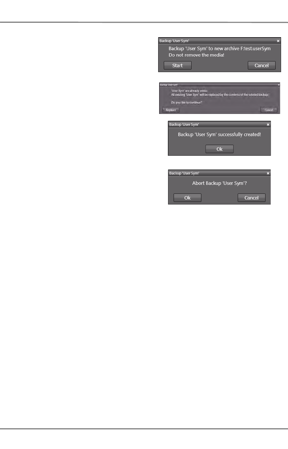
NACOS Platinum
ED 3100 G 140 / 04 (2011-11)
Operating Instructions
H-2 Data Maintenance of the Electronic Charts
H MAINTENANCE.fm / 10.11.11
H-14
7. Confirm the security advice clicking Start.
8. If the backup file already exists, the replace-
ment of this file must be confirmed.
9. A message window is shown after the backup
has been finished.
10. If it is desired, the backup progress can be
stopped by clicking on Abort in the tab
window. The abortion must be confirmed.
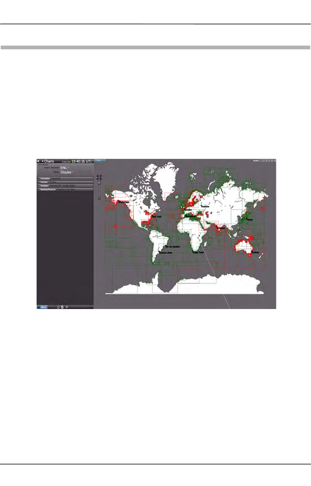
ED 3100 G 140 / 04 (2011-11)
Operating Instructions
H-3 Manual ENC Update Editor
H MAINTENANCE.fm / 10.11.11 H-15
NACOS Platinum
3 Manual ENC Update Editor
It is possible to edit the ENC charts and only these by means of a chart editor. The edited elements of
the chart are stored as a separate file. The ENC chart file itself is not modified. If the manually updated
chart is opened, the corresponding chart is displayed and in addition to the ENC Manual Update.
Opening the Chart Editor
In Super Home click on Nautical Charts.
The Overview of the installed charts is opened. This may take some time, because the database is
checked before the charts are displayed.
If no installed charts are displayed (no rectangles appear on the screen), open the Functions expander
and set Apply On to MFDn (this one).
Fig. H / 1 Nautical Charts Editor - Overview
Use the Pan and Zoom control and/or the Set Chart Center-function in order to navigate to the cell
that is to be updated. As already known, the chart can be shifted using the drag-and-drop functionality
by means of the More button.
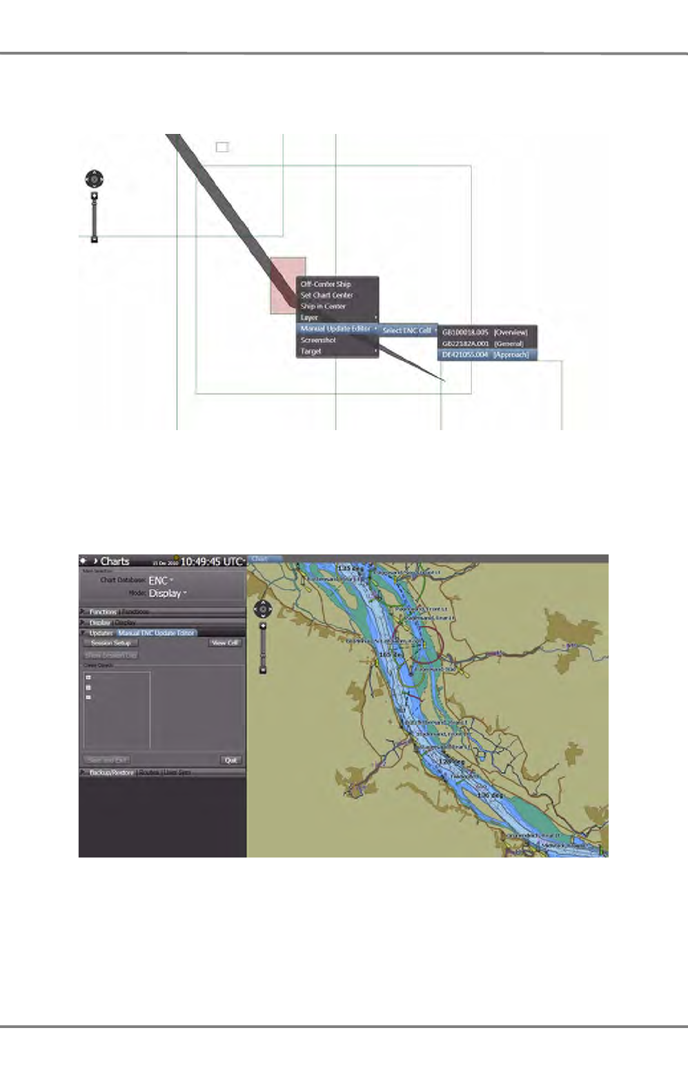
NACOS Platinum
ED 3100 G 140 / 04 (2011-11)
Operating Instructions
H-3 Manual ENC Update Editor
H MAINTENANCE.fm / 10.11.11
H-16
As soon as the desired cell is displayed, click it with More and choose Manual ENC Update Editor >
Select ENC Cell > and click the cell that is to be updated.
Fig. H / 2 Selecting a cell
The cell is displayed then. If it is not already opened, open the Updates expander.
The cell and its chart data can be updated now.
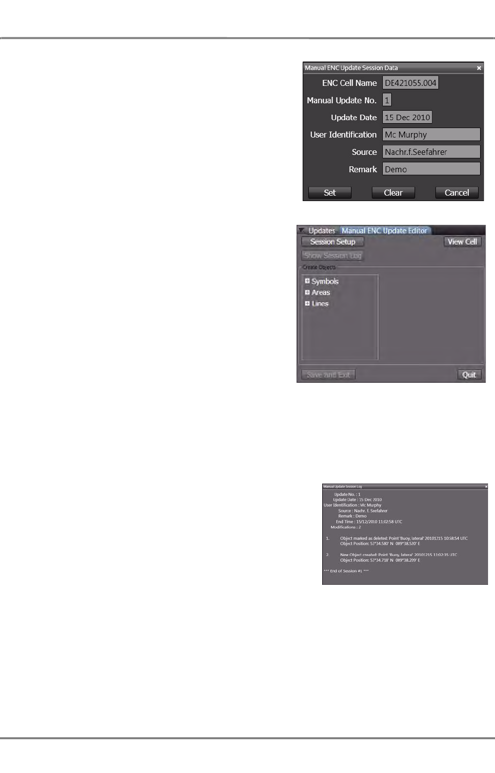
ED 3100 G 140 / 04 (2011-11)
Operating Instructions
H-3 Manual ENC Update Editor
H MAINTENANCE.fm / 10.11.11 H-17
NACOS Platinum
Click on Session Setup in the Update expander and
enter the Manual ENC Update Session Data. Then,
click on Set. A click on Clear will erase all entered data,
Cancel will close the window without any further action.
In the editor window the entries for the categories of
objects which can be edited are now active.
A click on View Cell will display the chosen cell with
maximum size, so that editing is as easy as possible.
Whenever the display of the cell has been resized or
shifted, a click on View Cell will display the cell again
with maximum size.
A new object can be placed now or existing objects can
be modified. This works in the same way as the usage of
User Symbols. See chapter A - 8 on page A-83 for
details. The update session can be ended clicking on
Quit.
All actions are stored in the session log, as long as the
session has not been ended by a click on Save and Exit. Once an update action has been carried out,
the control Quit changes its name to Undo and Abort. Using this control will lead to abortion of the
update process without changes.
If the operatior activates another application like RADAR or ECDIS while the manual ENC update is done,
the performed actions of the manual update do not get lost, in fact, all alterations will still be present
when the operator returns to the manual update editor.
To view the session log, click on Show Session Log.
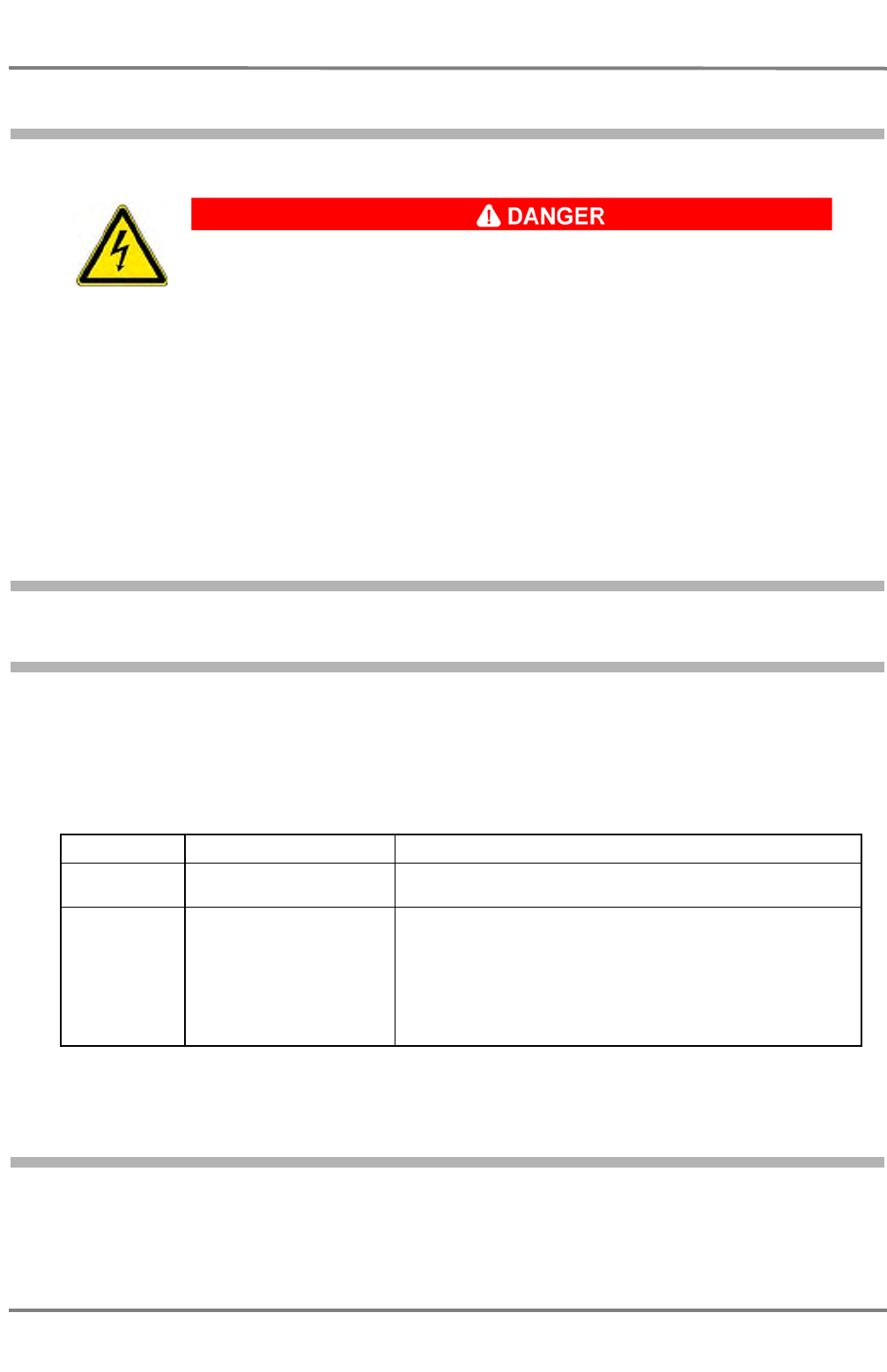
NACOS Platinum
ED 3100 G 140 / 04 (2011-11)
Operating Instructions
H-4 Hardware Maintenance
H MAINTENANCE.fm / 10.11.11
H-18
4 Hardware Maintenance
If these operating instructions require you to remove safety systems for maintenance work or repair, be
sure to reinstall them after finishing work. Only remove safety devices if this is necessary for the main-
tenance work or repair. This particularly applies to covers and ground cables.
4.1 Periodical Checks
4.1.1 Limited-Lifetime Devices
Within the radar system there are some devices or parts of units which have a limited lifetime. The
devices and their presumed lifetime are listed below. It must be considered that these devices shall be
checked periodically and exchanged if neccessary.
☞ For more information about the change of components like magnetron or toothed belts please refer
to the technical documentation
Table H / 1 Limited-Lifetime Devices
4.2 Check of the Colour Reproduction
The colour reproduction produced by the monitors must be correct. In the case of doubt and once per
year, the monitor performance must be checked based on the Chart1 presentation. See chapter 3.3 on
page B-14 for details.
HIGH VOLTAGE!
DANGER OF FATAL INJURIES
NEVER assume that a circuit is dead – Always check it for safety’s sake! Contact
with live parts can cause serious or fatal burns and inner injuries by electrocution.
This particularly applies to the Outstation cabinets which may contain components
to which 230 VAC or 400 VAC are applied.
Capacitors and tubes can store dangerous voltages for several hours, even when
they have been disconnected from the supply voltage.
Device Approx Lifetime Procedure
Magnetron X-Band ~6000 - 8000h
S-Band ~9000 - 16000h Monthly carry out the check of the performance monitor as
described. See chapter H - 1 on page H-3 for detais.
Toothed belts 12 months
Every 12 months or when the magnetron is exchanged,
change the toothed belt as described in the technical documen-
tation.
Every time the gear box is opened.
Check for mechanical damages as fissures or fractures on the
surface and for visible parts of the weft, especially at the
edges. If such damages are visible, the belts must be
exchanged.

ED 3100 G 140 / 04 (2011-11)
Operating Instructions
H-5 SW Version and Updates
H MAINTENANCE.fm / 10.11.11 H-19
NACOS Platinum
5 SW Version and Updates
5.1 SW Version
The SW version can be accessed from the Super Home page by opening the Menu on bottom left side
and clicking on About.
The About Information Window shows data as follows:
- Designation of the equipment with NACOS Platinum series
- Machine name of the display electronics, i.e. MFD 01
- SW version number and built number of the application SW package for the display electronics
- SW version number and if applicable built number of the connected data processing unit DPU 2010
or DCU 2010
5.2 SW Updates
Software updates can only be carried out by authorized service personell. For more information with
regards to software updates of ECDIS Systems or complete NACOS Systems please contact:
NACOS_update@sam-electronics.de.

NACOS Platinum
ED 3100 G 140 / 04 (2011-11)
Operating Instructions
H-5 SW Version and Updates
H MAINTENANCE.fm / 10.11.11
H-20


ALARMS

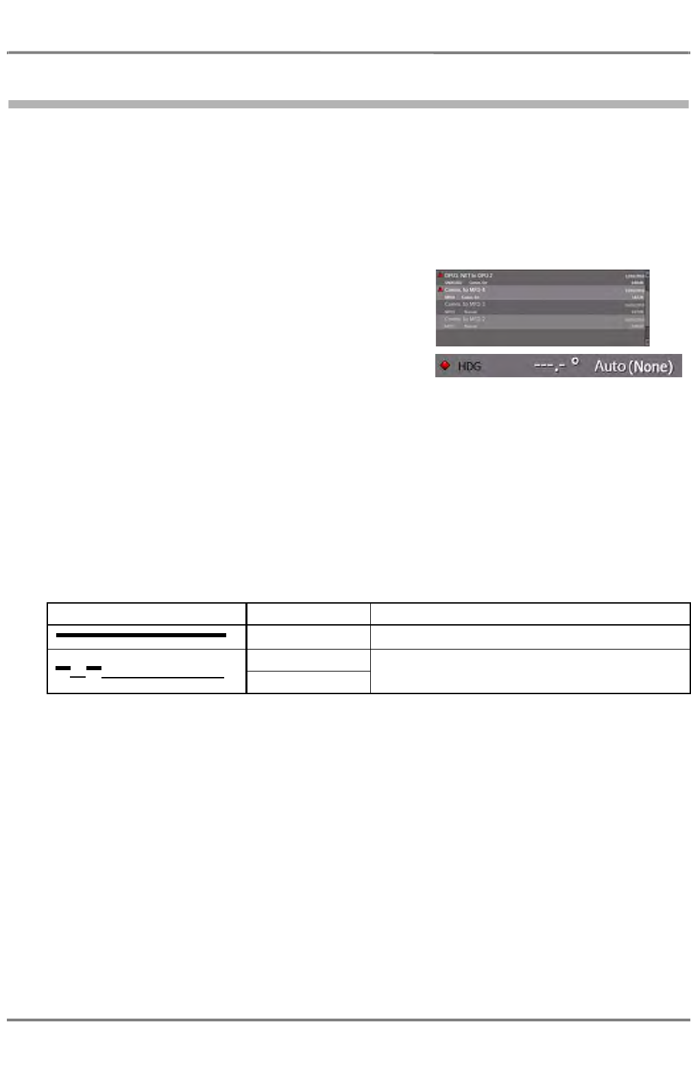
ED 3100 G 140 / 04 (2011-11)
Operating Instructions
V-1 General Information
V Alarms.fm / 10.11.11 V-3
NACOS Platinum
1 General Information
In NACOS Platinum all alarms will generally be indicated in the same way in all cases. Both alarms from
the automation system and alarms from the navigation system are shown in the same place and in the
same way but their availability on the different MFDs is depending on their specific configuration.
It has been chosen to indicate the different states of an alarm by different symbols in dedicated colors.
Furthermore, the alarms have different audible indications emitted by the buzzer which is installed in
every MFD.
The symbols will be used in the following manner:
- Placed in front of the alarm line in Alarm Lists
- Placed in front of the label in the permanent area of
RADAR and ECDIS as status indicators on other places of
the HMI.
If the automation system is configured for the MFD, symbols will also be used as follows:
- As a separate symbol in Mimic Diagrams for binary alarms. (e.g. used for a level switch in a tank).
- As a symbol placed behind the Unit of an analogue value displayed on a Mimic Diagram (e.g. used
for display of a temperature with a limit).
- As a symbol placed beside a Function Block symbol (indicating the state of machinery components,
e.g. pumps, valves, generators etc.
Alarms and Warnings can be accompanied by a sound signal. The possible sounds emitted by the buzzer
are as follows:
For warnings with priority 3 the sound can be deactivated by the operator (see xyz).
Sequence Meaning Description
Alarm (Priority 1) Permanent tone
Warning (Priority 2) tone (1 sec), pause (1 sec), tone (1 sec), pause (7 sec)
as warning(s) but suppressable
Warning (Priority 3)
...
...
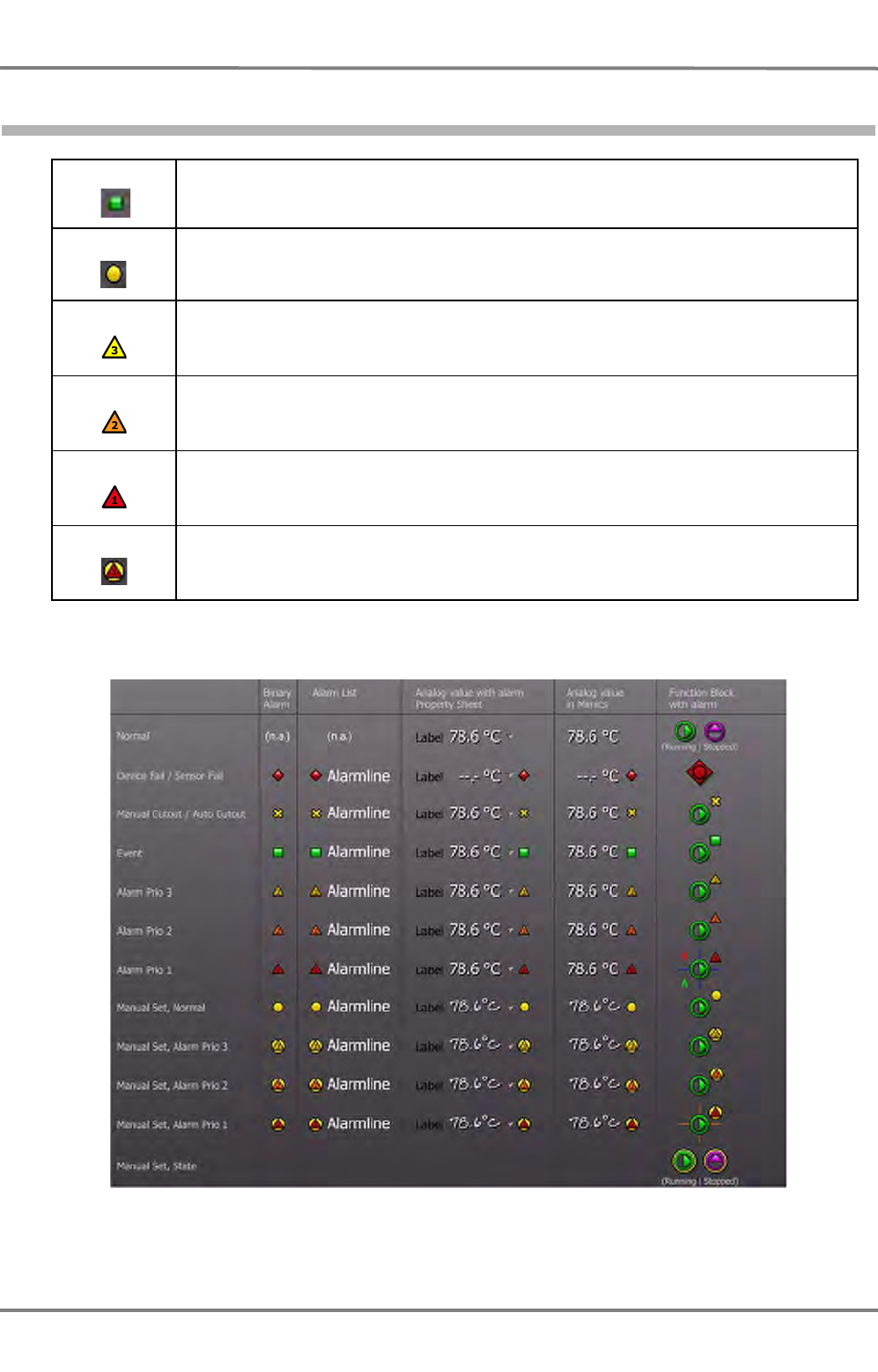
NACOS Platinum
ED 3100 G 140 / 04 (2011-11)
Operating Instructions
V-1 General Information
V Alarms.fm / 10.11.11
V-4
1.1 Colour code for the alarm indications:
Examples for alarm indications:
Fig. V / 1 Alarm Indications
Green Indication of an exceeded limit that shall not raise an alarm (Alarm priority 4).
Yellow Input from the process is disconnected in the software, and the value is entered manually by
the operator
Yellow Incidents and (pre)warnings, usually alarm priority 3. For alarms of this prority, the acoustic
alarm can be switched off
Orange Warnings and alarms that require immediate action, usually alarm priority 2
Red A serious event that has not been solved yet, usually alarm priority 1
Yellow & red A value that had been entered manually by the operator has caused an alarm priority 1
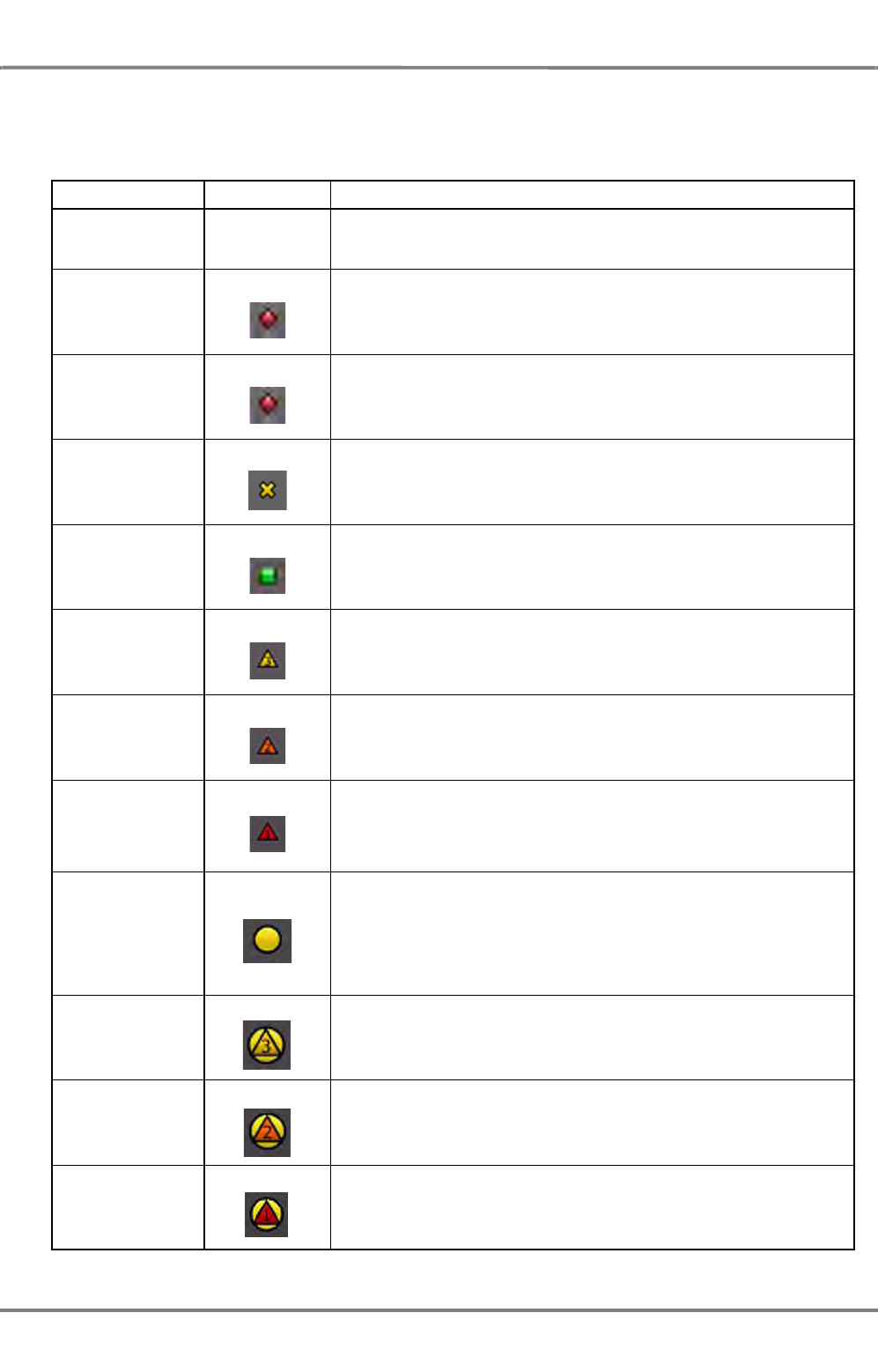
ED 3100 G 140 / 04 (2011-11)
Operating Instructions
V-1 General Information
V Alarms.fm / 10.11.11 V-5
NACOS Platinum
A flashing symbol for any alarm means that this alarm has not been acknowledged yet. A steady symbol
indicates an acknowledged status of an alarm, but that the cause for the alarm is still present.
An alarm can be of the following types:
State Symbol Explanation/Remarks
Normal - No errors in hardware/software and no limits exceeded
Device fail Error in the Control and Supervision system, the indication is invalid
Sensor fail The value received from the sensor is outside the legal limits
Manual Cut Out Alarm function is switched off by the operator. Alarm will never occur
even if limits are exceeded. Manual Cut Out is normally not used for
Function Blocks
Event Indication of an exceeded limit that shall not raise an alarm (Alarm
priority 4). This case is normally not indicated in the Mimic Diagram. In
some cases an indication for a binary input is displayed (e.g. Heater
switched on)
Alarm priority 3 Alarm with lowest priority. The alarm is indicated by a triangle (like a
traffic sign) in yellow. Inside the triangle the alarm priority is indicated
by the number 3, to improve readability for people with color blindness
(since prio 1 and 2 are also triangles)
Alarm priority 2 Alarm with middle priority. The alarm is indicated by a triangle (like a
traffic sign) in orange. Inside the triangle the alarm priority is indicated
by the number 2, to improve readability for people with color blindness
(since prio 1 and 3 are also triangles)
Alarm priority 1
Alarm with highest priority. The alarm is indicated by a triangle (like a
traffic sign) in red. (red is mandatory for highest priority alarm). Inside
the triangle the alarm priority is indicated by the number 1, to improve
readability for people with color blindness (since prio 2 and 3 are also
triangles)
Manual Set
Input from the process is disconnected in the software, and the value
is entered manually by the operator. In this case a blue circle is added
behind the actual alarm symbol, and for analogue values the font is
exchanged by a script font. For Function Blocks it is possible to make
"Manual Set" for both the alarm and the process feedback, so you may
have a blue circle behind the alarm icon and/or behind the state
symbol
Manual Set
Alarm priority 3 This is the same as the Manual Set described above. For this value
an alarm with priority 3 has occurred and is now indicated.
Manual Set
Alarm priority 2 This is the same as the Manual Set described above. For this value
an alarm with priority 2 has occurred and is now indicated.
Manual Set
Alarm priority 1 This is the same as the Manual Set described above. For this value
an alarm with priority 1 has occurred and is now indicated.
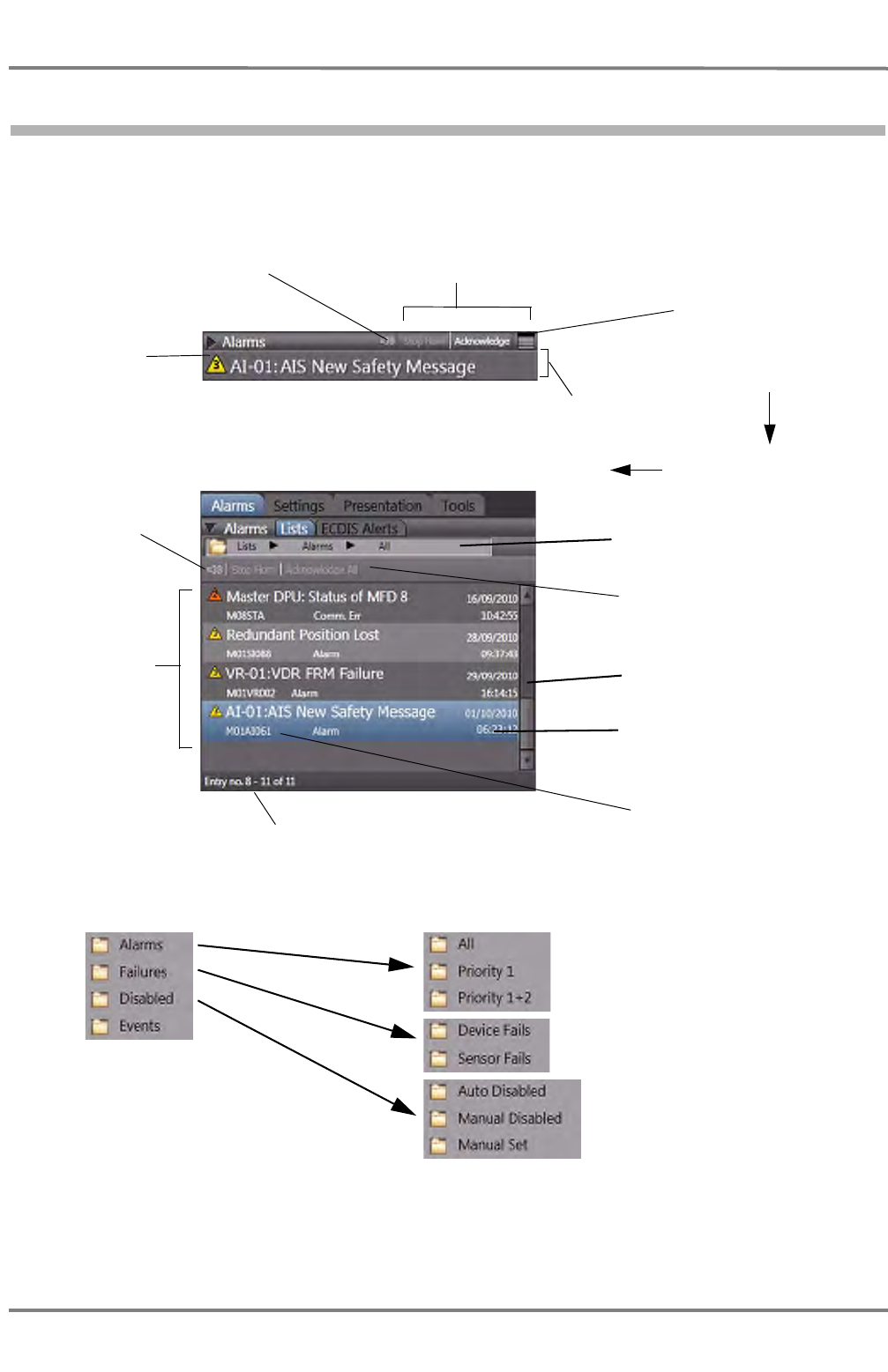
NACOS Platinum
ED 3100 G 140 / 04 (2011-11)
Operating Instructions
V-1 General Information
V Alarms.fm / 10.11.11
V-6
1.2 Overview of the alarm window
☞ If the alarm list is opened by the Alarm List icon (see above) or by a click on the Alarms Tab, it
always shows the complete list of alarms, warnings and indications, independent of the previously
made selections of filters or priorities in the list. The list then shows the newest alarm entry at the
bottom of the alarm window.
Alarm List.
To open, click on this
icon.
Alarm list in opened
state.
Oldest un-
acknowledged
alarm with
priority indica-
tion
Visual indication
for the horn
Buttons for
reactions to
alarms
displayed in the
list
Alarm list, the
first alarm has
been selected
by the operator.
Number of alarms, alarms eight
to eleven are visible in the list.
Newest Alarm. See
1.2.1 on page V-7 for
details.
Alarm list
scrollbar
Alarm Line:
(The alarm with highest priority is indicated here)
Alarms List:
Buttons for operator reac-
tions to the indicated alarm
Visual indication
for the horn Selection and indication
of listed alarm criteria
List Criteria:
By means of the list criteria, the
clearness of the list can be
improved. Only the chosen
criteria/subcriteria of alarms will
be displayed
Unit and application that have origi-
nated the alarm, alarm number and
status
To show the alarm-
source and state,
click on the line
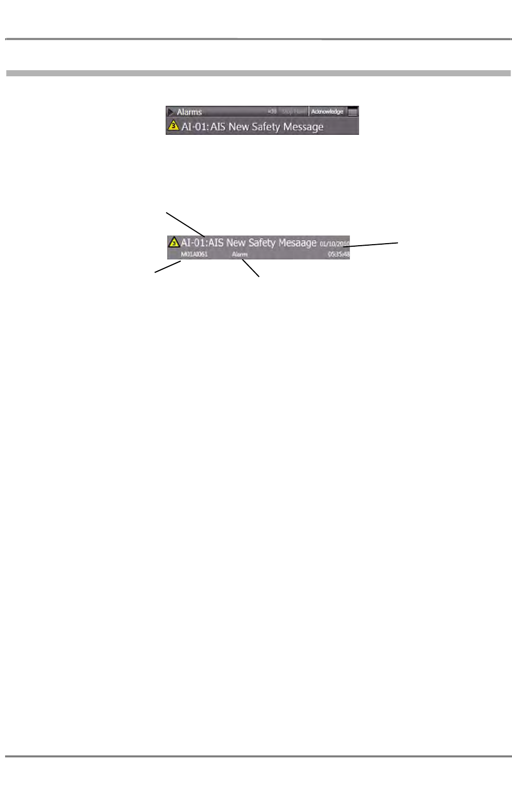
ED 3100 G 140 / 04 (2011-11)
Operating Instructions
V-1 General Information
V Alarms.fm / 10.11.11 V-7
NACOS Platinum
1.2.1 Example of an alarm
Additionally to the alarm designation, supplemental information are displayed for each active alarm in the
list. In this example, MFD M01 has originated the alarm:
The alarm number is M01AI061, where AI ist the indication for the AIS unit, 061 is the internal fault
number. See list of alarms for further information.
The status is Alarm, which means that the alarm is still active (in alarm state).
Status indications can be for example:
- Normal
- Alarm
- Sens Fail (Sensor Failure)
- Dev. Fail (Device Failure)
- Comm. Error (Communication Error)
- Ch. Error (Channel Error)
- SW. Error (Software Error)
Date and time of first
occurence of the alarm
Designation of the
alarm
MFD-Id, Application Id
and Alarm number Status

NACOS Platinum
ED 3100 G 140 / 04 (2011-11)
Operating Instructions
V-1 General Information
V Alarms.fm / 10.11.11
V-8

ED 3100 G 140 / 04 (2011-11)
Operating Instructions
V-2 Alarm Management
V Alarms.fm / 10.11.11 V-9
NACOS Platinum
2 Alarm Management

NACOS Platinum
ED 3100 G 140 / 04 (2011-11)
Operating Instructions
V-2 Alarm Management
V Alarms.fm / 10.11.11
V-10
2.1 Behaviour when an Alarm comes up
Whenever an alarm is raised, the processing is a two-step action:
1. Switch off the acoustic alarm, if there is one. Use the Stop Horn button in the GUI
or press the button on the keyboard, if it is available.
☞ Some alarms do not trigger the acoustic alarm. This depends on the settings made in the configu-
ration database of the Integration Manager.
☞ Some alarms can only be switched off at the MFD that has originated the alarm. For example, a
Trackpilot alarm can only be acknowledged at the MFD that is set as Trackpilot Master.
2. Immediately obtain information about the causes of the alarm or warning, about the system state
and about possible system reactions, and - if necessary - immediately perform all necessary actions
for the avoidance of possible danger.
3. Remove the cause of the alarm or warning: If an alarm has occurred due to a cause that can be
removed, that cause must be removed as quickly as possible; see also section V - 2.2: "List of
Alarms". Alarms with priority 4 disappear when the cause disappears. Acknowledgement is then
unnecessary. Alarms with priority 1, 2 and 3 must be acknowledged in any case.
4. The alarms with priority 1 and many alarms of priority 2 and 3 must be acknowledged if the situa-
tion allows or requires such acknowledgement. There are two possibilities to acknowledge alarms:
- Click on Acknowledge in the alarm line
- Click on Acknowledge All in the heading of the Alarm list
If alarms or warnings are also distributed to other items of equipment within the system, or if the system
deviates from the behaviour described above, e.g.
- if the alarm cannot be acknowledged at all or throughout the entire system, or
- if acknowledgement causes something to be initiated or enabled, or
- if an acknowledged alarm is repeated for as long as the cause of the alarm continues to exist.
These situations are mentioned in section V - 2.2: "List of Alarms".
Removing acknowledged alarms from the list is done automatically by the system, in case the alarm
reason is no longer valid, or the application or operating mode has been switched off.
Stop
Buzzer
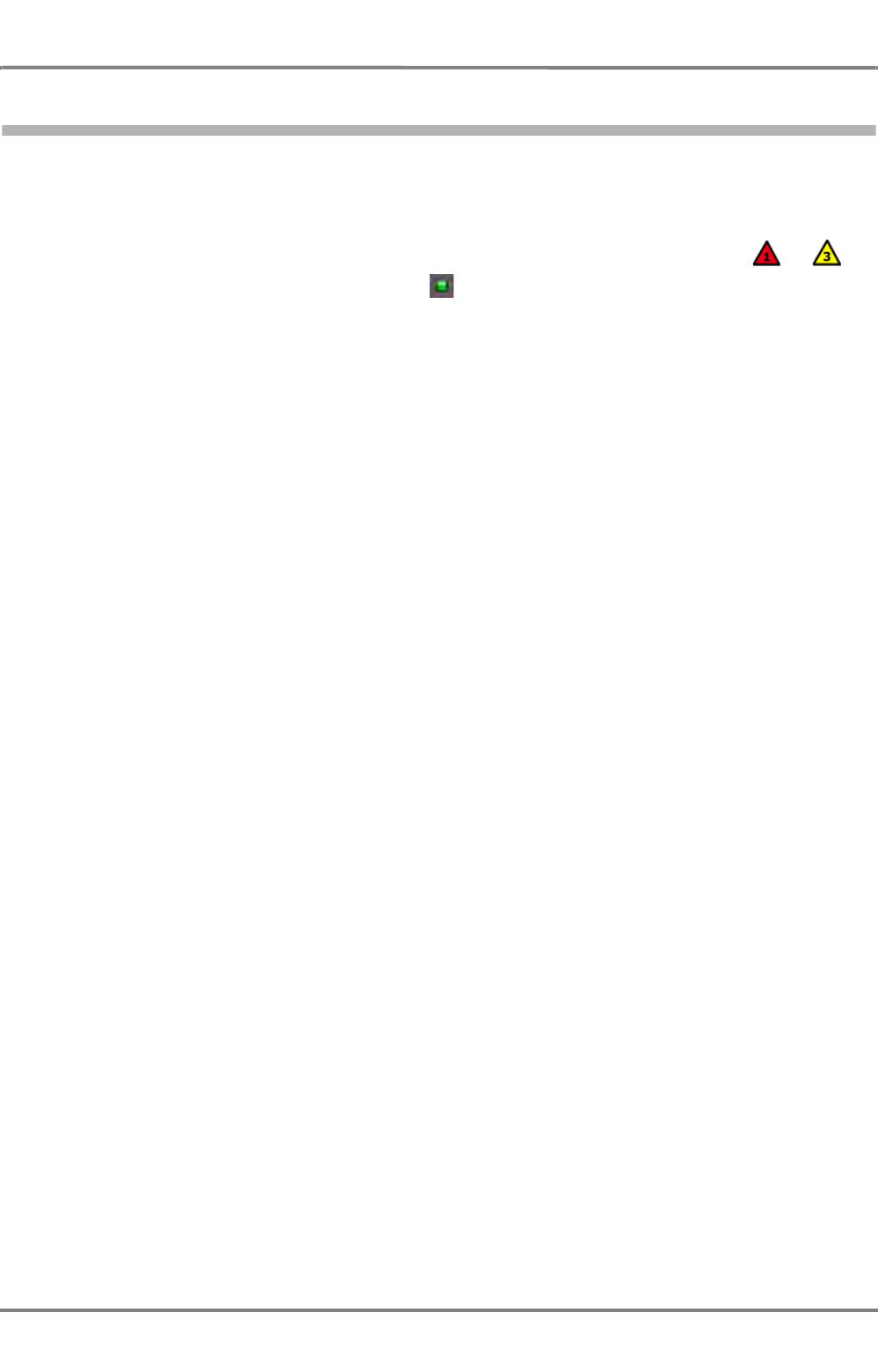
ED 3100 G 140 / 04 (2011-11)
Operating Instructions
V-2 Alarm Management
V Alarms.fm / 10.11.11 V-11
NACOS Platinum
2.2 List of Alarms
This chapter lists and describes all available pre-defined alarms, warnings and indications of the naviga-
tion system, i.e. Radar, ECDIS and the optional Trackpilot, as well as the AIS and the optional VDR.
Legend:
In front of each entry in the alarm list the priority is shown with the respective symbol ... .
Indications (events) are marked by the symbol on the screen, but not in the list on the next pages.
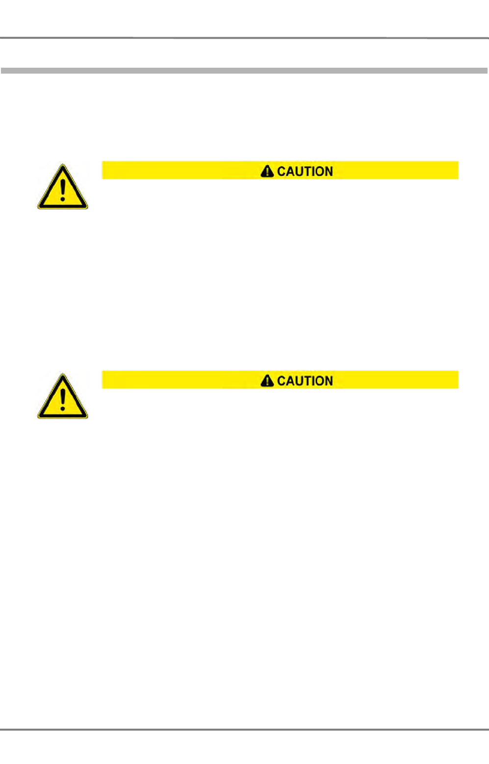
NACOS Platinum
ED 3100 G 140 / 04 (2011-11)
Operating Instructions
V-2 Alarm Management
V Alarms.fm / 10.11.11
V-12
2.2.1 Navigation Sensor Alarms
This chapter describes the navigation sensor alarms available in the system. The main navigation sensors
used for the heading, speed and position instruments are monitored depending on the “sensor selection
mode”. Those sensors which are available twice or more in the installation can be supported by an auto-
matic selection mode.
- If the selection mode is AUTO the switching over to another sensor of the same type is done
without any alarm or warning.
In AUTO mode the switch over to a manual sensor (Manual Speed or Manual Position) is only
accompanied by an alarm if the manual data have not been set before.
- If the Manual selection is chosen the switching over to the backup sensor must be done manually
after the respective alarm or warning has been given.
In the meantime (until a new sensor has been selected) the system is using the last valid values of
the disturbed or faulty sensor which produced the alarm.
It is required to perform the switch over to the new sensor a soon as possible, but not before its
data have been checked for plausibility and correctness.
Note:
- Depending on the status of the navigation sensors it may be possible that selected display or oper-
ation modes of the system are no longer available or may not be allowed by the approval authori-
ties.
- Details are given below as required in the explanations to the different sensor alarms.
The automatic selection mode is the default setting after start or restart of the
system.
In any case (in manual or automatic selection mode) the set data for the sensors
running in manual mode must be checked regularly and a real sensor must be
selected as soon as possible.
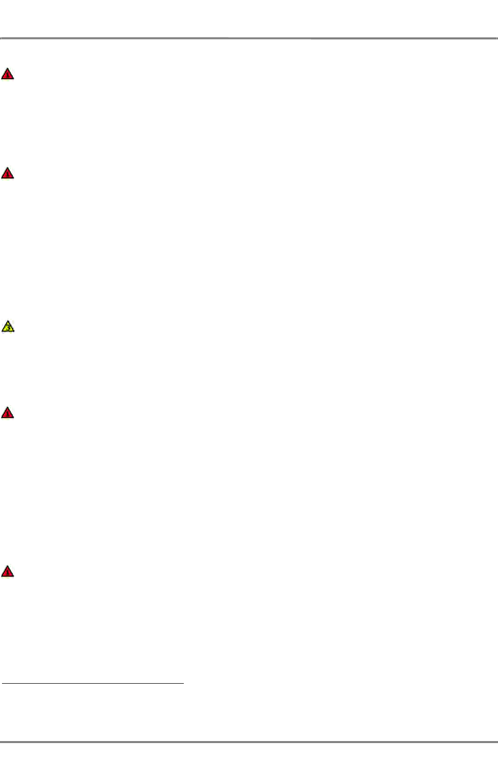
ED 3100 G 140 / 04 (2011-11)
Operating Instructions
V-2 Alarm Management
V Alarms.fm / 10.11.11 V-13
NACOS Platinum
Ground Speed Invalid
The selected COG/SOG speed sensor is sending invalid data. Another speed sensor will have to be
selected by the operator. At present, the speed that was last sent as the valid speed is being used.
Dashes are shown in the speed display field.
Special features: The alarm is distributed over the entire system. Acknowledgement is possible on
any MFD.
Ground Speed Timeout
Data are no longer being received from the selected COG/SOG speed sensor. Another speed sensor
will have to be selected by the operator. At present, the speed that was last sent as the valid speed
is being used,
-or-
The DCU connected to the system has failed. Acknowledgement is possible on any
indicator.
Special features: The alarm is distributed over the entire system. Acknowledgement is possible on
any indicator.
Ground Speed Valid
The speed sensor which had given the Ground Speed Invalid or Ground Speed Timeout alarm
is again sending valid data.
Special features: The warning is distributed over the entire system. Acknowledgement is possible
on any MFD.
Heading Invalid 1)
The heading sensor system has failed, or is reporting incorrect data,
-or-
The DCU connected to the system has failed.
Special feature: The alarm is distributed over the entire system. Acknowledgement is possible on
any MFD.
Remedy: Check the compass system, the signal transmission and the DCU.
When the TRACKPILOT is in an active steering mode, this alarm is repeated as TP Heading Sensor
Fault, which can be acknowledged finally on the TRACKPILOT Master only.
Heading Timeout 1)
Data are no longer being received from the selected heading sensor or from the DCU. Another
heading sensor will have to be selected by the operator if available.
Special feature: The alarm is distributed over the entire system. Acknowledgement is possible on
any MFD.
When the TRACKPILOT is in an active steering mode, this alarm is repeated as TP Heading Sensor
Fault, which can be acknowledged finally on the TRACKPILOT Master only.
1) All display objects and operating possibilities for which the heading information is required are no longer shown
or are inactive. If the cause of the alarm is not corrected within 30 seconds, the tracked targets are deleted on
the radar system.
NACOS Platinum
ED 3100 G 140 / 04 (2011-11)
Operating Instructions
V-2 Alarm Management
V Alarms.fm / 10.11.11
V-14
Heading Valid
The compass system is again sending valid data.
Special feature: The alarm is distributed over the entire system. Acknowledgement is possible on
any MFD.
Low Position Quality 1)
The selected position sensor has reported a greater position-deviation than is usual for this type of
sensor.
Special feature: The warning is distributed over the entire system.
Remedy: Check the position sensor; select some other position sensor.
New POSN Sensor Selected
The sensor selection for the connected position sensors is operating in AUTO mode and the previ-
ously used sensor is invalid or data are no longer received via the sensor interface. The new selected
sensor is indicated with its data, status and mode in the position instrument display.
☞ If you want to use another sensor than the automatically selected one, you must go to manual
selection mode by a click on the required sensor in the position sensor menu. A reactivation of AUTO
mode can only be done by the operator (Click on AUTO in the menu).
New HDG Sensor Selected
The sensor selection for the connected heading sensors is operating in AUTO mode and the previ-
ously used sensor is invalid or data are no longer received via the sensor interface. The new selected
sensor is indicated with its data, status and mode in the heading instrument display.
☞ If you want to use another sensor than the automatically selected one, you must go to manual
selection mode by a click on the required sensor in the heading sensor menu. A reactivation of AUTO
mode can only be done by the operator (Click on AUTO in the menu).
New SOG Sensor Selected
The sensor selection for the connected SOG sensors is operating in AUTO mode and the previously
used sensor is invalid or data are no longer received via the sensor interface. The new selected
sensor is indicated with its data, status and mode in the SOG instrument display.
☞ If you want to use another sensor than the automatically selected one, you must go to manual
selection mode by a click on the required sensor in the SOG sensor menu. A reactivation of AUTO
mode can only be done by the operator (Click on AUTO in the menu).
New STW Sensor Selected
The sensor selection for the connected STW sensors is operating in AUTO mode and the previously
used sensor is invalid or data are no longer received via the sensor interface. The new selected
sensor is indicated with its data, status and mode in the STW instrument display.
☞ If you want to use another sensor than the automatically selected one, you must go to manual
selection mode by a click on the required sensor in the STW sensor menu. A reactivation of AUTO
mode can only be done by the operator (Click on AUTO in the menu).
1) This alarm can only appear if activated on service level; it is required for ships with DNV NAUT-AW approval.
ED 3100 G 140 / 04 (2011-11)
Operating Instructions
V-2 Alarm Management
V Alarms.fm / 10.11.11 V-15
NACOS Platinum
No Valid Position Sensor
The position sensor selection is working in AUTO mode and has temporarily switched to dead reck-
oning (DR) mode,
-or-
The DCU connected to the system has failed. Acknowledgement is possible on any
indicator.
Special feature: As soon as possible the system will automatically switch to a valid position sensor
and deactivate this warning.
Remedy: Check/repair the the connected position sensors.
No WGS84 Position in Use
The selected position sensor
- is no longer reporting the WGS84 position datum
or
- is reporting another position datum than WGS84.
As a consequence the indicated and plotted positions could have deviations to the WGS84 system.
Remedy: Check the position sensor and the data sentences transmitted to NACOS. Ensure correct
transmission of the position datum sentence.
Position Invalid
The selected position sensor is sending invalid position data. Another position sensor will have to be
selected by the operator. During the transition period, the system determines the position by dead
reckoning (i.e. is internally temporarily switched to Estimated Position).
Special features: The alarm is distributed over the entire system. Acknowledgement is possible on
any MFD.
Position Timeout
Data are no longer being received from the selected position sensor,
-or-
The DCU connected to the system has failed.
Another position sensor will have to be selected by the operator. During the transition period, the
system determines the position by dead reckoning.
Special features: The alarm is distributed over the entire system. Acknowledgement is possible on
any MFD.
Position Valid
The position sensor which had given the Position Invalid or Position Timeout alarm is again
sending valid data again.
Special features: The warning is distributed over the entire system. Acknowledgement is possible
on any MFD.
NACOS Platinum
ED 3100 G 140 / 04 (2011-11)
Operating Instructions
V-2 Alarm Management
V Alarms.fm / 10.11.11
V-16
Redundant Gyro Differs
The difference between the headings of the selected heading sensor and of the redundant heading
sensor exceeds a specified alarm limit.
Special features: This warning can occur simultaneously on more than one of the system's items
of equipment.
Remedy:
- Check the available heading sensors, their mode and data
Redundant Gyro Lost
No valid heading is received from the redundant heading sensor. The heading monitoring no longer
takes place while the cause of the warning still exists.
Redundant Position Differs
The difference between the positions of the selected position sensor and of the redundant position
sensor exceeds a specified alarm limit.
Special features: This warning can occur simultaneously on more than one of the system's items
of equipment.
Remedy:
- Check the available position sensors, their mode and data
Redundant Position Lost
No valid position is received from the redundant position sensor. The position monitoring no longer
takes place while the cause of the warning still exists.
Water Speed Invalid
The selected STW speed sensor is sending invalid data. Another water speed sensor will have to be
selected by the operator. At present, the speed that was last sent as the valid speed is being used.
Special features: The alarm is distributed over the entire system. Acknowledgement is possible on
any MFD.
Water Speed Timeout
Data are no longer being received from the selected water speed sensor or from the DCU. Another
water speed sensor will have to be selected by the operator. At present, the speed that was last
sent as the valid speed is being used.
Special features: The alarm is distributed over the entire system. Acknowledgement is possible on
any MFD.
Water Speed Valid
The speed sensor which had given the Water Speed Invalid or Water Speed Timeout alarm is
again sending valid data.
Special features: The warning is distributed over the entire system. Acknowledgement is possible
on any MFD.
ED 3100 G 140 / 04 (2011-11)
Operating Instructions
V-2 Alarm Management
V Alarms.fm / 10.11.11 V-17
NACOS Platinum
2.2.2 RADAR Alarms
ACQ Zone Overflow
A target has been acquired automatically in the guard zone. It cannot be tracked, because the
maximum number of targets 1) are already being tracked.
Remedy: Check the acquisition/guard zone; delete targets.
ARPA TGT Capacity Limit
100% of the maximum number of ARPA targets are being tracked.
Remedy: Delete at least one unimportant target.
Check ARPA Target Capacity
95% of the maximum number of ARPA targets are being tracked.
Remedy: Delete at least one unimportant target
Dangerous Target
The target situated at the displayed red flashing symbol has become a dangerous target, because
the CPA and TCPA values have become smaller than the limits that were set for them.
Lost Target 2)
The tracked target situated at the displayed lost target symbol has got lost.
Special feature: For this warning it is possible to switch off the acoustic signal.
Magnetron Fault
The selected transceiver is reporting magnetron overcurrent.
Special feature: Acknowledgement is performed by switching the radar over to stand-by.
Remedy: Switch the transceiver over to stand-by, and then switch it back to radar operation. If the
warning occurs repeatedly, request service.
No Antenna Azimuth
The azimuth angle information of the antenna is missing.
Remedy:
- If the antenna is not rotating: check the ship's mains and/or the antenna fuse or circuit-
breaker. If the antenna is rotating: request service.
- Select another radar transceiver
No Headmarker
The antenna's headmarker signal is missing.
Remedy:
1) ARPA targets and AIS targets together
2) For AIS targets the Lost Target warning can be disabled in the Settings - Target menu.
NACOS Platinum
ED 3100 G 140 / 04 (2011-11)
Operating Instructions
V-2 Alarm Management
V Alarms.fm / 10.11.11
V-18
- If the antenna is not rotating: check the ship's mains and/or the antenna fuse or circuit-
breaker. If the antenna is rotating: request service.
- Select another radar transceiver
No Radar Video
The system is in a faulty condition, such that the radar video cannot be generated.
Remedy:
- Check the radar transceiver
- Check the antenna
- Select another radar transceiver
Request service.
No Trigger
The radar transmission trigger is missing, the radar video cannot be displayed.
Remedy:
- Check the radar transceiver.
- Select another radar transceiver
Target AUTO-Acquired
A target which is not yet being tracked has been acquired automatically in the acquisition/guard
zone.
TGT Entered Guard Zone
A target which is already being tracked has entered the acquisition/guard zone.
ED 3100 G 140 / 04 (2011-11)
Operating Instructions
V-2 Alarm Management
V Alarms.fm / 10.11.11 V-19
NACOS Platinum
2.2.3 AIS Alarms
Depending on the type of AIS connected to the system, not all alarms and warnings listed below may
be supported.
Nevertheless all AIS alarms which are implemented in the NACOS Platinum are listed here completely.
The AIS related target alarms and warnings are documented in the chapter Radar Alarms, they are not
repeated here.
The following warnings and alarms are only available in the system, if an AIS receiver is connected.
AIS Ch.Man. Not Accepted
The settings made for the channel management have not been accepted by the system.
Remedy: Check the settings.
AIS Check TGT Capacity
95% of the maximum number of AIS targets are being tracked.
Remedy: Delete at least one unimportant AIS target.
AIS External POSN Lost
The AIS system does not receive a valid position sensor information and falls back to its internal
position sensor.
Remedy: Check the sensor and the cabling.
AIS General Failure
The AIS has stopped the transmission caused by an internal fault.
Remedy: Call service as soon as possible. The AIS system must be exchanged probably.
AIS GPS Antenna Failure
The GPS antenna of the AIS does not work correctly.
Remedy: Check the GPS antenna and the antenna cabling (short circuit or missing contact at the
connectors). No immediate action is required, AIS is normally fed by an external GPS receiver from
the integrated bridge system.
AIS GPS ANT Short Circ.
The internal check of the GPS receiver has detected a short circuit in the coax wire between the
antenna and the receiver.
Remedy: Check the GPS antenna cable.
AIS GPS Receiver Fault
The GPS receiver of the AIS has detected an internal malfunction.
Remedy: Call service at the next possible harbour. The transmitter is still operable, your vessel wil
still be visible for other ships, but you might not see other AIS tragets.
NACOS Platinum
ED 3100 G 140 / 04 (2011-11)
Operating Instructions
V-2 Alarm Management
V Alarms.fm / 10.11.11
V-20
AIS TGT Capacity Limit
100% of the maximum number of acquired AIS targets are being tracked.
Remedy: Delete at least one unimportant AIS target.
AIS New Safety Message
The AIS has received a safety message.
The safety message can be read under > Tools > Target > Message.
AIS No Valid COG
The AIS system has no valid course over ground information.
Remedy: Check the connected sensor and cabling. (Typically the COG information from an inte-
grated bridge system which is derived from a GPS sensor, the AIS will continue to work but will
transmit less information to other ships.)
AIS No Valid Heading
The AIS system has no valid heading information from the sensor.
Remedy: Check the heading sensor. (Typically the heading information from an integrated bridge
system which is derived from the gyro, the AIS will continue to work but will transmit less informa-
tion to other ships.)
AIS No Valid Position
The AIS system has no valid position information from internal position sensor
Remedy: Check the cabling and the antenna of the internal GPS sensor. (Typically the position
information from an integrated bridge system which is derived from a GPS sensor, the AIS will
continue to work with its own sensor, but the position, which is sent out to other ships might not
be as accurate as before)
AIS No Valid ROT
The AIS has no valid rate of turn information from the sensor.
Remedy: Check the sensor and the cabling. (Typically the rate of turn information from an inte-
grated bridge system which is derived from the gyro, the AIS will continue to work but will transmit
less information to other ships)
AIS No Valid SOG
The AIS has no valid speed over ground information.
Remedy: Check selected speed sensor. (Typically the SOG information from an integrated bridge
system which is derived from a GPS sensor, the AIS will continue to work with its own sensor, but
the speed, which is sent out to other ships might not be as accurate as before)
AIS Offline
Remedy: Check the AIS system. It might be possible to eliminate the fault by switching the voltage
supply to the AIS electronics unit off and then on again at the ship's mains.
ED 3100 G 140 / 04 (2011-11)
Operating Instructions
V-2 Alarm Management
V Alarms.fm / 10.11.11 V-21
NACOS Platinum
AIS Oper. Unit Offline
The indicator electronic does not communicate with the AIS electronics unit. The AIS continues
operating.
Remedy: Check the cabling and connection between RADAR and AIS system.
AIS RX Ch. A Malfunction
The AIS stopped the transmission on the channel A.
Remedy: The AIS system must be exchanged.
AIS RX Ch. B Malfunction
The AIS stopped the transmission on the channel B.
Remedy: The AIS system must be exchanged.
AIS RX DSC Malfunction
The AIS stopped the transmission on the channel 70.
Remedy: The AIS system must be exchanged.
AIS TX Malfunction
The AIS system stopped transmission.
Remedy: Check the AIS system. Check the antenna and the antenna cabling (short circuit or
missing contact at the connectors). Call the service at the next possible harbour, be aware that your
ship might not be visible for other ships as an AIS target.
AIS VSWR Limit Exceeded
The AIS system continues operation: The VSWR (voltage standing wave ratio) checked by the AIS
is out of range. The distance from where your own ship is visible for other ships a an AIS target is
significantly reduced to a very few miles only.
Remedy: Check the AIS system. Check of the AIS UHF antenna, antenna cabling and connectors.
NACOS Platinum
ED 3100 G 140 / 04 (2011-11)
Operating Instructions
V-2 Alarm Management
V Alarms.fm / 10.11.11
V-22
2.2.4 ECDIS Alarms
Approach to Waypoint
The ship is approaching a critical point on the pre-planned track, for example the WOP (wheel over
point), which is indicating the approach to the next course change manoeuvre on the route.
Special feature: This alarm can be activated or suppressed on the Alarms expander under ECDIS
Alerts with the selection of Critical point on route alarm.
Area w. Special Condition
The chart monitoring detected an area with special conditions (for example a user made Danger
Highlight Area) ahead of the own ship´s position.
☞ For this alarm it is possible to select wether it is supposed to be an alarm with priority 1 or an indi-
cation.
Area w. Special Condition
☞ For this indication it is also possible to select wether it is supposed to be an alarm with priority 1
or an indication.
Crossing a Danger
An obstruction, a wreck, rock with depth below the user selected safety depth or Aids to Navigation
or a user made Safety Line will be crossed soon or is touched by the guard sector set for the ECDIS..
Crossing Safety Contour
The ship or its guard sector has actually crossed a depth limit for which this alarm has been acti-
vated in the Alarms > ECDIS Alerts dialog.
Deviation from Route
The current position of the ship deviates from the planned position according to the route that has
been computed by the Route Editor. The limits of the cross track deviation can be altered in the
XTD LIM column of the Route Editor.
ED 3100 G 140 / 04 (2011-11)
Operating Instructions
V-2 Alarm Management
V Alarms.fm / 10.11.11 V-23
NACOS Platinum
2.2.5 Trackpilot Alarms
The following list of alarms, warnings and indications contains all alarms for all operating modes
(Heading, Course, Track) of the TRACKPILOT. In systems with Heading mode only, alarms of the Course
and Track mode are not initiated.
TP Astern Speed
The TRACKPILOT is in the activated state and the selected speed sensor is producing negative
(astern) speed data (which the TRACKPILOT cannot process).
WARNING: While this alarm is present, the steering gear is not being driven by the TRACKPILOT.
When the TP Astern Speed alarm appears, it is necessary to immediately change to some other
speed sensor or to switch over to manual steering.
Special feature: The alarm cannot be acknowledged. It is repeated and disappears when its cause
has been eliminated.
TP Backup Navigator Alarm
The TRACKPILOT Alarm signal was generated.
Causes for generating the TRACKPILOT Alarm signal: See 2.2.6 on page V-32.
Special feature: As long as the TP Backup Navigator Alarm alarm has not been acknowledged,
the TRACKPILOT Alarm signal remains active.
TP Change Position Sensor
While the system is in Track mode,
- the selected position sensor has not transferred any valid data for a longer period, or
- a switch-over has taken place to a position sensor which is not transmitting valid data, or
- a switch-over has taken place to a position sensor which is not permitted as a continuous
sensor for Track mode.
- or -
While a position sensor is being used which is not permitted as a continuous sensor for Track mode,
a switch-over to Track mode has taken place.
Special features: Until the cause of the alarm has been eliminated, the alarm is repeated after 1
minute. The TP Track Mode Fault alarm appears after 10 minutes if the cause of the alarm has
not yet been eliminated
Remedy: Select a position sensor with valid data, or a permitted position sensor.
TP Course Limit
The set course limit has been exceeded.
Remedy:
- Increase the course limit or
- wait until the TRACKPILOT has eliminated the course deviation, or
- switch over to manual steering.
NACOS Platinum
ED 3100 G 140 / 04 (2011-11)
Operating Instructions
V-2 Alarm Management
V Alarms.fm / 10.11.11
V-24
TP Deactivated
The TRACKPILOT has been deactivated and is no longer controlling the rudder. The ship must be
steered manually or by another autopilot.
NOTE: This alarm is optional and must be configured on service level if required by the class or the
owner.
TP Drift Angle Limit
The pre-set drift limit value for the Trackpilot has been exceeded; for correct course or track-
keeping, a larger compensation angle is needed.
☞ Even after acknowledgement, the drift angle contained in the actual course is limited for the TRACK-
PILOT to the drift limit setting.
Remedy: Increase the drift limit value or switch over to Heading mode or to manual steering.
TP End of Track
The ship, sailing in Track mode, will pass the last waypoint of the System Route in 60 seconds.
Special features: Acknowledgement causes a switch-over to Course mode; the ship’s course has
to be set manually from now on.
If the alarm is not acknowledged within 30 seconds, the Trackpilot Alarm signal is generated for
the purposes of triggering an external alarm. See 2.2.6 on page V-32.
TP GC Course Change
Track mode is switched on and the sailing mode is set to Great Circle. In order to remain on the
Great Circle, a course change is necessary which exceeds 3 degrees or half of the set Course Limit.
The new course is displayed as Next course in the TRACKPILOT data display.
Special features: Acknowledge with Execute. Regardless of whether this alarm is acknowledged
or not, the planned change of the course takes place at the WOP.
TP Heading Change Due to Drift
The ship is sailing in Course mode or Track mode and a drift change of more than 5° has occurred
as a result of switch-over (manual or automatic) of the selected SOG speed sensor.
Special feature: Up until acknowledgement takes place, the TRACKPILOT uses the longitudinal and
transverse speeds that were valid before the alarm. After acknowledgement, the TRACKPILOT uses
the new longitudinal and transverse speeds, so that a heading change which is of the same order
of magnitude as the drift difference occurs automatically.
Remedy: Select Heading mode to avoid any heading change caused by a switch over of the speed
sensor.
TP Heading Sensor Fault
The TRACKPILOT is in the activated state and the compass system or its transmission unit has
been switched off, is reporting incorrect data, or has failed.
- or -
With the TRACKPILOT in the activated state, the gyro heading value
- has jumped by more than 1 degree betwen two high speed transmissions.
ED 3100 G 140 / 04 (2011-11)
Operating Instructions
V-2 Alarm Management
V Alarms.fm / 10.11.11 V-25
NACOS Platinum
Special features:
- Acknowledgement causes switch-over to Heading mode and acceptance of the displayed gyro
heading value. The currently existing heading value is taken over as the set value.
- In addition, acknowledgement can force the TRACKPILOT to generate larger rudder angles.
- If the cause of the alarm has not been removed (i.e. the gyro heading is still invalid), the alarm
is repeated even after acknowledgement.
If the alarm is not acknowledged within 30 seconds, the TRACKPILOT Alarm signal is
generated for the purposes of triggering an external alarm. See 2.2.6 on page V-32
Remedy (after the switch-over to manual steering has taken place):
Check the compass system; if possible at the compass system, select another heading source. Check
the displayed heading before use.
TP High Rudder Limit (high ROT) 1)
The TRACKPILOT internal monitoring function of the rudder limit, set by the operator, has deter-
mined that with this maximum rudder deflection at the currently sailed speed a high rate of turn
above the limit would be produced.
Special feature: This warning cannot be acknowledged, it will disappear if the cause for this
warning has been eliminated.
Remedy: Decrease the rudder limit or reduce the speed.
TP Low Rudder Limit 2)
The rudder limit is set so low that - during Track mode - the next course-change possibly cannot
be performed with the planned radius.
Remedy: Increase the rudder limit, increase the radius, or leave the Track mode.
TP Low Speed
The speed reported by the selected speed sensor is so low that the TRACKPILOT might not be able
to steer the ship correctly.
Special feature: Acknowledgement causes a switch-over to Heading mode.
Remedy: Switch over to manual steering.
TP Low Track Limit2)
The track limit setting is lower than the expected average position-error of the selected position
sensor.
Remedy: Increase the track limit or select a more accurate position sensor.
While this alarm is present, the steering gear is not being driven by the TRACK-
PILOT.When this alarm appears, a switch-over to manual steering must be
performed immediately.
1) This alarm can only appear if activated on service level; for this function a maximum allowed ROT value must be
set in the system configuration.
2) This alarm can only appear if activated on service level; required for ships with DNV NAUT-AW approval.
NACOS Platinum
ED 3100 G 140 / 04 (2011-11)
Operating Instructions
V-2 Alarm Management
V Alarms.fm / 10.11.11
V-26
TP Low Water Speed
The speed through the water (STW) of the selected sensor is so low that the TRACKPILOT might
not be able to steer the ship correctly.
☞ This alarm can only appear if a speed sensor providing STW is installed but has not been selected
as system speed input.
Remedy: Switch over to manual steering, if it is obvious, that the TRACKPILOT is not able to steer
the ship correctly.
TP No Master MFD Selected
There is no MFD defined as the TRACKPILOT Master by user selection.
Special features: Acknowledgement can also be performed by clicking on the button
or by pressing the TrackPilot Master key on the keyboard.
The MFD on which acknowledgement takes place is automatically switched to act as the TRACK-
PILOT Master.
TP Position Drift 1)
Since the beginning of the long-term position drift computation in Track mode, a difference has built
up between the dead reckoning position and the position given by the position sensor, and this
difference is greater than a limit value which depends on the set track limit 2) or on the sensor selec-
tion.
Special feature: Acknowledgement restarts the position drift calculation with a difference of zero.
Remedy:
- Select a more accurate position sensor or speed sensor or correct the manual set and drift
input.
- Select Manual DR (Dead Reckoning) instead of the position sensor and check the navigation
sensors presently used.
- Switch over to Course mode or Heading mode.
- Increase the track limit.2)
TP Position Jump
During steering in Track Mode a position jump (e.g. mode change of the sensor, new sensor selec-
tion or manual position adjust) exceeding the set track limit (or, if the track limit is set to a low
value, a position jump exceeding a value which depends on the sensor type) has been detected.
Special feature: By acknowledgement, the new position is accepted.
Remedy: Increasing the track limit increases the tolerance with regard to position jumps and
strengthens the filtering of the received position-data.
1) Depending on the system configuration this alarm can be switched off on service level.
2) In the case of ships with DNV NAUT-AW approval, the limit value depends not on the track limit but on the
selected speed sensor and on the selected position sensor.
ED 3100 G 140 / 04 (2011-11)
Operating Instructions
V-2 Alarm Management
V Alarms.fm / 10.11.11 V-27
NACOS Platinum
TP Reduced Radius
The Track mode is in the switched-on state, but the set radius for the next turn is too large to
enable the ship to reach the next leg by means of the manoeuvre that is planned at the TO-
waypoint. For this reason, the TRACKPILOT will reduce the radius to such an extent that the course
change can be performed.
☞ A reduced radius can result in an increased ROT during the planned turn.
Remedy: Switch over to Course mode or Heading mode.
TP Rudder Error
The rudder engine is not obeying the instructions from the TRACKPILOT, or is not doing so with
sufficient accuracy.
Special feature: The message initially appears as an indication without an acoustic signal. If the
cause of the fault continues to exist for more than 10 seconds, the acoustic alarm signal appears
additionally and the priority is increased to Alarm (1). The alarm can be acknowledged, but is
repeated for as long as the cause of the fault continues to exist.
Remedy: Check the steering gear, the rudder pumps and the TRACKPILOT interface.
TP Rudder Feedback Differs
The signal of the main rudder feedback unit deviates by at least 5 degrees from the signal received
from the redundant rudder feedback unit.
Remedy: Switch over to manual steering. Check the rudder feedback units (wiring, signal, mechan-
ical function).
TP Rudder Limit
The set rudder limit value has been reached; with this rudder limit, the activated manoeuvre can
most probably not be performed without a deviation
- or -
The present rudder angle lies outside the rudder limit.
Remedy:
- Increase the rudder limit or
- wait until the rudder angle becomes less than the rudder limit or
- switch over to manual steering.
If this alarm is present for a longer time, it is necessary to switch over to manual
steering.
In Track mode on ships with DNV NAUT-AW approval, limitation by the set rudder
limit is ignored when a planned manoeuvre is being performed (i.e. during the
turn at the waypoint) 1).
1) This function must be enabled on service level.
NACOS Platinum
ED 3100 G 140 / 04 (2011-11)
Operating Instructions
V-2 Alarm Management
V Alarms.fm / 10.11.11
V-28
TP Rudder Relay Failure
An error has occurred in the relay controlled rudder control system.
Remedy: Switch over to manual steering. Check the rudder control system (wiring, steering relays
etc.).
TP Rudder Synch. Error
The rudder angles of the two rudders controlled by the TRACKPILOT differ by at least 5 degrees.
Remedy: Switch over to manual steering. Check the rudder control system and the synchronism of
the rudders.
TP Short Radius
So that the planned manoeuvre can be performed with the actually set radius, the expected rudder
angle would have to be larger than the maximum value that the TRACKPILOT can apply.
Remedy: Increase the radius or switch over to manual steering.
TP Speed Jump
The speed transferred from the selected speed sensor has jumped by more than 5 knots.
Special feature: Up until acknowledgement takes place, the TRACKPILOT uses the longitudinal and
transverse speeds that were valid before the alarm. After acknowledgement, the TRACKPILOT uses
the new longitudinal and transverse speeds.
Remedy: Check the new speed value. If it is correct, acknowledge the alarm; otherwise, select
some other speed sensor before acknowledgement.
TP Speed Sensor Fault
The TRACKPILOT is in an active steering mode and the selected speed sensor is reporting incorrect
data or has failed; steering with the drift angle taken into account is not possible.
- or -
The TRACKPILOT had been operated in Track mode and the selected sensor is reporting incorrect
data or has failed or Manual Speed has been selected as the speed sensor. When the alarm appears,
the system is automatically switched over to the Heading mode.
Special feature: For as long as no valid speed data are being received, the alarm is repeated.
Remedy: Select some other speed sensor or change to manual steering.
TP Track Data Error
The TRACKPILOT reports transfer errors or data errors of the activated System Route or the route
was deactivated by the operator.
Remedy: Switch to Course mode or Heading mode or manual steering. Check the waypoint data,
of the activated route. Deactivate and activate the route again.
If this alarm appears, the data of the pre-planned track are unreliable. The track
data must not be used for navigation.
ED 3100 G 140 / 04 (2011-11)
Operating Instructions
V-2 Alarm Management
V Alarms.fm / 10.11.11 V-29
NACOS Platinum
TP Track Limit
The track limit value set by the operator or taken from the activated route has been exceeded.
Remedy:
- Increase the track limit or
- allow the ship to steer back to the track or
- steer the ship with the joystick or
- select manual steering.
TP Track Mode Aborted 1)
By operation of the joystick, the Mode buttons or the Mode keys (HDG, CRS) on the keyboard, the
TRACKPILOT was switched from Track mode to Course Mode or Heading Mode.
TP Track Mode Fault 1)
The system was in Track mode, but the speed data, position data or waypoint data are no longer
available or valid during sailing in Track mode.
- or -
The set course limit or the set track limit is exceeded for the track that was just recalculated.
- or -
The system was in Track mode and the latitude 85° has been exceeded.
The system therefore automatically switches over to the Course mode.
Special features: If the alarm is not acknowledged within 30 seconds, the TRACKPILOT Alarm
signal is generated additionally for the purposes of triggering an external alarm. See 2.2.6 on page
V-32.
Remedy: Select some other speed or position sensor or define a new route as the System Route
or - after the course deviation or track deviation has fallen below the limit - activate Track mode
again.
TP Waypoint Approaching
The early course change indication announces, that the WOP of the TO-waypoint will be reached in
XX seconds.
XX = advance warning time which, according to section V - 2.2.4: "ECDIS Alarms" , has been
entered for the occurrence of this alarm in the TP-Settings dialog under WPT Approach.
The distance and the time to go to the WOP as well as the Next track course and radius are
displayed in the Route Data display.
TP WOP Execution
In Track mode the next WOP (the starting of the course change on the leg) will be reached 30
seconds after this warning or alarm appears.
Special feature: Acknowledge with Execute
1) On ships with DNV NAUT-AW approval, this alarm also appears if the Chart Monitoring Offline or Conning
System Offline alarm occurred.
NACOS Platinum
ED 3100 G 140 / 04 (2011-11)
Operating Instructions
V-2 Alarm Management
V Alarms.fm / 10.11.11
V-30
If the planned change of the course is not to be executed: Switch over to Course or Heading
mode and steer with the joystick or appologize a manual steering mode.
If the preceding TP Waypoint Approaching warning has been acknowledged, the TP WOP
Execution alarm appears initially as a warning, with a low intensity acoustic signal. If the TP
Waypoint Approaching warning was not acknowledged, the TP WOP Execution alarm appears
together with an intensive acoustic signal.
If the warning TP WOP Execution is not acknowledged within 30 seconds, an intensive acoustic
signal is generated even if the TP WPT Waypoint Approaching alarm was acknowledged before-
hand. If not acknowleged 30 seconds after appearance of the WOP alarm, the TRACKPILOT Alarm
signal is generated for the purpose of triggering an external back up navigator alarm. See 2.2.6 on
page V-32.
☞ If the manoeuvre period from one wheel-over point to the following one is less than 30 seconds,
the TP WOP Execution alarm of the second wheel-over point does not appear until after the first
wheel-over point has been passed but already during execution of the first manoeuvre.
TP Trackpilot Failure
The TRACKPILOT reports an internal fault, and is no longer controlling the rudder.
☞ Until the cause of the alarm has been eliminated, the status FAILURE is shown in the operational
mode field of the TRACKPILOT data display as well as on the Conning display.
Remedy (after the switch-over to manual steering has taken place):
- Attempt to reconnect the Trackpilot to the steering gear.
- Restart the TRACKPILOT (See 2.8 on page G-49 for details).
- Check the TRACKPILOT electronics unit, the TRACKPILOT Interface and their power supply.
If installed, switch over to the second TRACKPILOT.
Regardless of whether this alarm is acknowledged or not, the planned change of
the course takes place at the WOP.
When this alarm appears, a switch-over to manual steering must be performed
immediately.
ED 3100 G 140 / 04 (2011-11)
Operating Instructions
V-2 Alarm Management
V Alarms.fm / 10.11.11 V-31
NACOS Platinum
Trackpilot System Failure
a) For systems with one TRACKPILOT
The communication between the MFD and the TRACKPILOT has failed.
☞ Until the cause of the alarm has been eliminated, the word FAILURE is shown in the operational
mode field of the TRACKPILOT data display.
Remedy (after the switch-over to manual steering has taken place):
- Restart the TRACKPILOT (See 2.8 on page G-49)
- Check the TRACKPILOT electronics unit, the TRACKPILOT Interface and their power supply.
b) For systems with two TRACKPILOTs, a TRACKPILOT is connected to the steering gear
The communication between the MFD and the activated TRACKPILOT has failed.
Special Feature: Through the acknowledgement, the other TRACKPILOT is selected but not acti-
vated.
Remedy:
- Activate the other TRACKPILOT.
- Restart the TRACKPILOT which has generated the alarm. (See 2.8 on page G-49)
- Check the TRACKPILOT electronics unit and the TRACKPILOT Interface of the TRACKPILOT
which has generated the alarm.
c) For systems with two TRACKPILOTs, no TRACKPILOT is connected to the steering gear
The communication between the MFD and both TRACKPILOTs has failed.
☞ Until the cause of the alarm has been eliminated, the word FAILURE is shown in the operational
mode field of the TRACKPILOT data display.
Remedy:
- Restart both TRACKPILOTs (See 2.8 on page G-49)
- Check both TRACKPILOT electronics unit, both TRACKPILOT Interface and their power supply.
When this alarm appears, a switch-over to manual steering must be performed
immediately.
When this alarm appears, a switch-over to manual steering or to the other
TRACKPILOT must be performed immediately.

NACOS Platinum
ED 3100 G 140 / 04 (2011-11)
Operating Instructions
V-2 Alarm Management
V Alarms.fm / 10.11.11
V-32
2.2.6 Trackpilot Alarm Signal Outputs
Additional to the alarms, warnings and indications of the TRACKPILOT on the MFD, there are different
alarm outputs available on the interconnection board of the TRACKPILOT-Interface. The designations and
functions of these isolated relay outputs are listed below.
Please refer to the Technical Manual for more information.
Trackpilot Failure Alarm
The TRACKPILOT interface puts out this signal if
- there is no operating unit switched to act as the TRACKPILOT Master for more than 30 sec
(the TP No Master MFD Selected alarm has been triggered), or
- the TP Heading Sensor Fault alarm has been triggered, or
- the TP Astern Speed alarm has been triggered, or
- the TP Trackpilot Failure alarm has been triggered, or
- the Trackpilot System Failure alarm has been triggered, or
- the TRACKPILOT electronics unit or the TRACKPILOT Interface unit has been switched off,
or
- the supply voltage of the TRACKPILOT Electronics unit or of the TRACKPILOT Interface unit
lies outside of the specification.
TRACKPILOT Power Alarm
The TRACKPILOT interface activates this signal if
- the TRACKPILOT Electronics unit has been switched off, or
- the supply voltage of the TRACKPILOT Electronics unit lies outside of the specification.
TRACKPILOT Alarm
The TRACKPILOT Interface outputs this signal if
- the TP Heading Sensor Fault alarm appeared 30s ago and this alarm has not been acknowl-
edged
- in Track Mode the TP Change Position Sensor alarm appeared 1-2 minutes ago and has
not been acknowledged
- a wheel-over point has been passed but the TP WOP Execution alarm for this wheel-over
point has not been acknowledged, or
- the TP End Of Track alarm appeared 30 seconds ago and this alarm has not been acknowl-
edged, or
- the TP Track Mode Fault alarm appeared 30 seconds ago and this alarm has not been
acknowledged.

ED 3100 G 140 / 04 (2011-11)
Operating Instructions
V-2 Alarm Management
V Alarms.fm / 10.11.11 V-33
NACOS Platinum
In addition, at service level, it can be specified which of the following reasons are to cause the output
of this signal too:
- The TP Waypoint Approaching alarm appeared 30 seconds ago and this alarm has not been
acknowledged.
- The TP Track Limit alarm has been triggered. 1)
- The TP Course Limit alarm has been triggered. 1)
At service level, the signal output can be set for the TP Track Limit and TP Course Limit alarms in
such a way that it takes place after a delay of 30 seconds.
The TRACKPILOT Alarm signal disappears as soon as the cause of the alarm is remedied or the alarm
that triggered the TRACKPILOT Alarm signal has been acknowledged.
At service level, it is possible to define that the TP Backup Navigator Alarm alarm appears at the
TRACKPILOT Master as soon as the TRACKPILOT Alarm signal is triggered. With this setting, the
TRACKPILOT Alarm signal remains active until the reason for the TP Alarm is no longer valid and the
TP Backup Navigator Alarm alarm is also acknowledged 2).
TRACKPILOT Rudder Alarm
The TRACKPILOT interface outputs this signal if
- the TP Rudder Feedback Differs alarm has been triggered, or
- the TP Rudder Relay Failure alarm has been triggered, or
- the TP Rudder Sync. Error alarm has been triggered.
1) DNV requires BN alarm, issued 30 sec after TL and CL alarm without acknowledgement by the operator.
2) The Trackpilot Alarm contact is used as the required system´s back-up navigator alarm output in installations with
a connection to external Bridge Alarm/Watch Alarm Transfer systems.
NACOS Platinum
ED 3100 G 140 / 04 (2011-11)
Operating Instructions
V-2 Alarm Management
V Alarms.fm / 10.11.11
V-34
2.2.7 VDR Alarms
The following warnings and alarms are only available in the NACOS Platinum system, if a VDR DEBEG
4300 or 4350 is connected via its LAN interface.
VDR Backup is running
In the voyage data recorder, an incident backup is running.
Special feature: The indication cannot be acknowledged. It disappears when the backup has been
finished.
This indication can occur simultaneously on more than one MFD.
VDR FRM Failure
The Final Recording Medium is defective, or the data transfer to it is faulty.
Special feature: This warning can occur simultaneously on more than one MFD.
Remedy: Check the VDR.
VDR Integrity Failed
A fault or failure has been detected by the BITE (Built-In Test Equipment) of the VDR.
Special feature: This warning can occur simultaneously on more than one MFD.
Remedy: Carry out a restart of the VDR; see page 175. Check the VDR.
VDR Main Power Failure
The uninterruptible power supply (UPS) of the VDR is no longer being supplied with power by the ship's
mains. The VDR is supplied with power by the UPS for at least 2 hours.
Special feature: This warning can occur simultaneously on more than one MFD.
Remedy: Secure the supply of power from the ship's mains to the UPS.
VDR Microphone Failed
The microphone test automatically performed by the VDR has shown that at least the recording function
of one of the microphones is faulty.
Special feature: This warning can occur simultaneously on more than one MFD.
Remedy: Check the VDR.
VDR Offline
The system has no contact to the voyage data recorder.
Special feature: The warning cannot be acknowledged. It disappears when its cause has been elimi-
nated.
Remedy: Check the VDR and the LAN connections.

ED 3100 G 140 / 04 (2011-11)
Operating Instructions
V-2 Alarm Management
V Alarms.fm / 10.11.11 V-35
NACOS Platinum
2.2.8 Machinery Alarms
System Alarms
Besides the alerts delivered by the different applications running on the MFD or which are received from
the connected equipment, sub-systems and sensors, there is a list of alarms, warnings and indications
which can additionally be issued by the integrated system and displayed on any MFD.
These alerts are not connected to any application but to a system monitoring process running partly on
each MFD and on the Data Processing Unit.
The possible systems alarms are very much depending on the installed system structure and components
available on board and they are therefore part of the configuration database created for your ship.
The following list of alarms can therefore only be an example, covering the most probable alarms which
can be expected on small systems as shown in Figure I / 2 (an IMO RADAR Set with 2 RADARs) or larger
systems as shown in Figure I / 4 (a system for large ships).
Master DPU: Status of DPU 2
The DPU or DCU which is currently running as the master has detected a problem with the secondary
DPU.
Master DPU: Status of MFD (1 … N)
The DPU or DCU which is currently running as the master has detected a problem with one of the
installed MFDs. (1 … N) is indicating the range of identification number of the MFDs.
DPU 1: SIO card 1 Channel (n)
The DPU or DCU has detected a problem with one of the installed serial I/O cards.
(n) is indicating the channel number on the SIO.
DPU 1: SIO card 2 Channel (n)
The DPU or DCU has detected a problem with one of the installed serial I/O cards.
(n) is indicating the channel number on the SIO.
DPU 1: SIO on CPU Board
The DPU or DCU has detected a problem with the on-board serial I/O channel.
Module 01C2C001 (SIO 2010) err
The serial I/O module with the identification 01C2C001 is reporting an internal error.
Note:
As soon as you add a Monitoring and Control System (MCS) as part of the NACOS Platinum, the number
of integrated and ship dependent monitoring and alarm functions will be increased significantly. In this
case refer also to the Commissioning Protocol which includes the complete list of alarms for the system
installed on your ship. This document should also be available in printed form in the ship's files.
The alarm priority of these alarms is generally defined by the system configuration which is only acces-
sible by the so called Integration Manager, an offline tool for the manufacturer's commissioning and
service organisation. The output of this tool is a database which is loaded into the system (the MFDs and
the DPUs) after the database has been adapted to the system structure and its interfaces.

NACOS Platinum
ED 3100 G 140 / 04 (2011-11)
Operating Instructions
V-2 Alarm Management
V Alarms.fm / 10.11.11
V-36
Refer to the part D Machinery MCS Platinum in these operating instructions for a comprehensive descrip-
tion of the MCS integrated alarm system with all its sub-functions and possible settings.

LISTS AND INDEXES


ED 3100 G 140 / Rev 04 (2011-11)
Operating Instructions List of Figures
OI_ANC2010_LOF.fm VI-3
NACOS Platinum
List of Figures
Fig. I / 1 MFD console design. . . . . . . . . . . . . . . . . . . . . . . . . . . . . . . . . . . . . . . . . . . . . . . . . . . . . . . I-22
Fig. I / 2 Minimum installation – IMO set. . . . . . . . . . . . . . . . . . . . . . . . . . . . . . . . . . . . . . . . . . . . . . . I-23
Fig. I / 3 Example of a small-ship installation. . . . . . . . . . . . . . . . . . . . . . . . . . . . . . . . . . . . . . . . . . . . I-24
Fig. I / 4 Example of a large-ship installation . . . . . . . . . . . . . . . . . . . . . . . . . . . . . . . . . . . . . . . . . . . . I-24
Fig. I / 5 MFD. . . . . . . . . . . . . . . . . . . . . . . . . . . . . . . . . . . . . . . . . . . . . . . . . . . . . . . . . . . . . . . . . . I-28
Fig. I / 6 Possible pointing devices . . . . . . . . . . . . . . . . . . . . . . . . . . . . . . . . . . . . . . . . . . . . . . . . . . . I-30
Fig. I / 7 Keyboard of a console . . . . . . . . . . . . . . . . . . . . . . . . . . . . . . . . . . . . . . . . . . . . . . . . . . . . . I-32
Fig. I / 8 Onscreen keyboard . . . . . . . . . . . . . . . . . . . . . . . . . . . . . . . . . . . . . . . . . . . . . . . . . . . . . . . I-32
Fig. I / 9 The Optional ASCII Keyboard . . . . . . . . . . . . . . . . . . . . . . . . . . . . . . . . . . . . . . . . . . . . . . . . I-33
Fig. I / 10 The RADAR Keyboard. . . . . . . . . . . . . . . . . . . . . . . . . . . . . . . . . . . . . . . . . . . . . . . . . . . . . I-34
Fig. I / 11 The Trackpilot Keyboard. . . . . . . . . . . . . . . . . . . . . . . . . . . . . . . . . . . . . . . . . . . . . . . . . . . I-35
Fig. I / 12 Date and Time Display . . . . . . . . . . . . . . . . . . . . . . . . . . . . . . . . . . . . . . . . . . . . . . . . . . . . I-43
Fig. I / 13 Example of Super Home. . . . . . . . . . . . . . . . . . . . . . . . . . . . . . . . . . . . . . . . . . . . . . . . . . . I-46
Fig. I / 14 General screen layout of the NACOS Platinum (RADAR Mode) . . . . . . . . . . . . . . . . . . . . . . . . I-47
Fig. I / 15 NACOS Platinum title bar of RADAR application. . . . . . . . . . . . . . . . . . . . . . . . . . . . . . . . . . . I-48
Fig. I / 16 Color schemes of the Color & settings. . . . . . . . . . . . . . . . . . . . . . . . . . . . . . . . . . . . . . . . . I-48
Fig. I / 17 Active Application Title . . . . . . . . . . . . . . . . . . . . . . . . . . . . . . . . . . . . . . . . . . . . . . . . . . . . I-49
Fig. I / 18 RADAR sidebar . . . . . . . . . . . . . . . . . . . . . . . . . . . . . . . . . . . . . . . . . . . . . . . . . . . . . . . . . I-51
Fig. I / 19 Sidebar – permanent area of the RADAR application . . . . . . . . . . . . . . . . . . . . . . . . . . . . . . . I-52
Fig. I / 20 Sidebar – example of the non-permanent area of the RADAR application . . . . . . . . . . . . . . . . I-54
Fig. I / 21 Opened NACOS Platinum main menu. . . . . . . . . . . . . . . . . . . . . . . . . . . . . . . . . . . . . . . . . . I-56
Fig. I / 22 ECDIS in full screen mode . . . . . . . . . . . . . . . . . . . . . . . . . . . . . . . . . . . . . . . . . . . . . . . . . I-58
Fig. I / 23 Application area frames . . . . . . . . . . . . . . . . . . . . . . . . . . . . . . . . . . . . . . . . . . . . . . . . . . . I-60
Fig. I / 24 Example: Machinery screen with three frames . . . . . . . . . . . . . . . . . . . . . . . . . . . . . . . . . . . I-60
Fig. I / 25 Example: Machinery screen with tabbed panels in three frames . . . . . . . . . . . . . . . . . . . . . . . I-62
Fig. I / 26 Tab after using tear-off function . . . . . . . . . . . . . . . . . . . . . . . . . . . . . . . . . . . . . . . . . . . . . I-63
Fig. I / 27 Example 1: Target List in RADAR sidebar . . . . . . . . . . . . . . . . . . . . . . . . . . . . . . . . . . . . . . . I-64
Fig. I / 28 Example 2: Alarm List. . . . . . . . . . . . . . . . . . . . . . . . . . . . . . . . . . . . . . . . . . . . . . . . . . . . . I-64
Fig. I / 29 Tooltip of a menu item . . . . . . . . . . . . . . . . . . . . . . . . . . . . . . . . . . . . . . . . . . . . . . . . . . . . I-68
Fig. I / 30 Examples of NACOS Platinum controls . . . . . . . . . . . . . . . . . . . . . . . . . . . . . . . . . . . . . . . . . I-69
Fig. I / 31 Zoom and pan control . . . . . . . . . . . . . . . . . . . . . . . . . . . . . . . . . . . . . . . . . . . . . . . . . . . . I-79
Fig. I / 32 Visualisation types of indication. . . . . . . . . . . . . . . . . . . . . . . . . . . . . . . . . . . . . . . . . . . . . . I-80
Fig. I / 33 Example of alarm types . . . . . . . . . . . . . . . . . . . . . . . . . . . . . . . . . . . . . . . . . . . . . . . . . . . I-81
Fig. III / 1 Overview of the RADAR Screen. . . . . . . . . . . . . . . . . . . . . . . . . . . . . . . . . . . . . . . . . . . . . . III-5
Fig. III / 2 Overview of the Chartradar Screen . . . . . . . . . . . . . . . . . . . . . . . . . . . . . . . . . . . . . . . . . . . III-6
Fig. III / 3 Overview of the ECDIS Screen . . . . . . . . . . . . . . . . . . . . . . . . . . . . . . . . . . . . . . . . . . . . . . III-7
Fig. III / 4 Overview of the Conning Screen. . . . . . . . . . . . . . . . . . . . . . . . . . . . . . . . . . . . . . . . . . . . . III-8
Fig. III / 5 Overview of the Trackpilot Expander. . . . . . . . . . . . . . . . . . . . . . . . . . . . . . . . . . . . . . . . . . III-9
Fig. III / 6 Overview of the Machinery Screen . . . . . . . . . . . . . . . . . . . . . . . . . . . . . . . . . . . . . . . . . . III-10
Fig. III / 7 Common Functions for Products and Applications. . . . . . . . . . . . . . . . . . . . . . . . . . . . . . . . III-11
Fig. III / 8 CCRP on RADAR . . . . . . . . . . . . . . . . . . . . . . . . . . . . . . . . . . . . . . . . . . . . . . . . . . . . . . . III-16
Fig. III / 9 CCRP on ECDIS. . . . . . . . . . . . . . . . . . . . . . . . . . . . . . . . . . . . . . . . . . . . . . . . . . . . . . . . III-17
Fig. III / 10 Structure of Context Menus . . . . . . . . . . . . . . . . . . . . . . . . . . . . . . . . . . . . . . . . . . . . . . III-19
Fig. III / 11 Layer Context Menu. . . . . . . . . . . . . . . . . . . . . . . . . . . . . . . . . . . . . . . . . . . . . . . . . . . . III-20
Fig. III / 12 The Chart Information window . . . . . . . . . . . . . . . . . . . . . . . . . . . . . . . . . . . . . . . . . . . . III-21
Fig. III / 13 Permanent Area for Navigation . . . . . . . . . . . . . . . . . . . . . . . . . . . . . . . . . . . . . . . . . . . . III-23
Fig. III / 14 Display in the modes True Motion and Centered Display . . . . . . . . . . . . . . . . . . . . . . . . . . III-31
Fig. III / 15 Display in the modes North-Up RM, Course-Up RM and Head-Up RM . . . . . . . . . . . . . . . . . III-32
Fig. III / 16 The Chart Status Line . . . . . . . . . . . . . . . . . . . . . . . . . . . . . . . . . . . . . . . . . . . . . . . . . . III-56
Fig. A / 1 IMO-Set installation. . . . . . . . . . . . . . . . . . . . . . . . . . . . . . . . . . . . . . . . . . . . . . . . . . . . . . . A-8
Fig. A / 2 INS-5 Installation . . . . . . . . . . . . . . . . . . . . . . . . . . . . . . . . . . . . . . . . . . . . . . . . . . . . . . . . A-9
Fig. A / 3 Radial and azimuthal distortions of the radar video . . . . . . . . . . . . . . . . . . . . . . . . . . . . . . . A-16
Fig. A / 4 Reduced Range of First Detection in Dependance or Precipitation in X-Band. . . . . . . . . . . . . . A-18

NACOS Platinum
ED 3100 G 140 / Rev 04 (2011-11)
Operating Instructions
List of Figures
OI_ANC2010_LOF.fm
VI-4
Fig. A / 5 Reduced Range of First Detection in Dependance or Precipitation in S-Band . . . . . . . . . . . . . . A-18
Fig. A / 6 The RADAR Keyboard . . . . . . . . . . . . . . . . . . . . . . . . . . . . . . . . . . . . . . . . . . . . . . . . . . . . A-29
Fig. A / 7 Overview of the RADAR screen . . . . . . . . . . . . . . . . . . . . . . . . . . . . . . . . . . . . . . . . . . . . . . A-31
Fig. A / 8 PPI with superimposed elements. . . . . . . . . . . . . . . . . . . . . . . . . . . . . . . . . . . . . . . . . . . . . A-33
Fig. A / 9 Zoom and Pan Control . . . . . . . . . . . . . . . . . . . . . . . . . . . . . . . . . . . . . . . . . . . . . . . . . . . . A-34
Fig. A / 10 An Overview of the Permanent Area of the RADAR . . . . . . . . . . . . . . . . . . . . . . . . . . . . . . . A-37
Fig. A / 11 RADAR Sidebar of the Non-Permanent Area . . . . . . . . . . . . . . . . . . . . . . . . . . . . . . . . . . . . A-53
Fig. A / 12 Data of the Selected Target . . . . . . . . . . . . . . . . . . . . . . . . . . . . . . . . . . . . . . . . . . . . . . . A-60
Fig. A / 13 The Target List . . . . . . . . . . . . . . . . . . . . . . . . . . . . . . . . . . . . . . . . . . . . . . . . . . . . . . . . A-68
Fig. A / 14 Marked Target. . . . . . . . . . . . . . . . . . . . . . . . . . . . . . . . . . . . . . . . . . . . . . . . . . . . . . . . . A-69
Fig. A / 15 Target Details . . . . . . . . . . . . . . . . . . . . . . . . . . . . . . . . . . . . . . . . . . . . . . . . . . . . . . . . . A-69
Fig. A / 16 Vector Display in Trial Manoeuvre Mode. . . . . . . . . . . . . . . . . . . . . . . . . . . . . . . . . . . . . . . A-74
Fig. A / 17 Delay in Trial Manoeuvre . . . . . . . . . . . . . . . . . . . . . . . . . . . . . . . . . . . . . . . . . . . . . . . . . A-75
Fig. A / 18 Checking the Trial Manoeuvre. . . . . . . . . . . . . . . . . . . . . . . . . . . . . . . . . . . . . . . . . . . . . . A-77
Fig. A / 19 ARPA Training Display . . . . . . . . . . . . . . . . . . . . . . . . . . . . . . . . . . . . . . . . . . . . . . . . . . . A-80
Fig. A / 20 User symbols on the electronic chart . . . . . . . . . . . . . . . . . . . . . . . . . . . . . . . . . . . . . . . . . A-84
Fig. A / 21 Planned track with Clearing Line (Not More Than 025°). . . . . . . . . . . . . . . . . . . . . . . . . . . . A-91
Fig. A / 22 Overview of the CHARTRADAR screen . . . . . . . . . . . . . . . . . . . . . . . . . . . . . . . . . . . . . . . . A-94
Fig. A / 23 CHARTRADAR Application Area with superimposed elements . . . . . . . . . . . . . . . . . . . . . . . A-102
Fig. A / 24 Diagram of the depth contour system . . . . . . . . . . . . . . . . . . . . . . . . . . . . . . . . . . . . . . . A-104
Fig. A / 25 The Depth Panel . . . . . . . . . . . . . . . . . . . . . . . . . . . . . . . . . . . . . . . . . . . . . . . . . . . . . . A-105
Fig. A / 26 Overview of the Chart Maintenance Screen . . . . . . . . . . . . . . . . . . . . . . . . . . . . . . . . . . . A-109
Fig. C / 1 Planned Route. . . . . . . . . . . . . . . . . . . . . . . . . . . . . . . . . . . . . . . . . . . . . . . . . . . . . . . . . . . C-3
Fig. C / 2 Shape of the pre-planned track in the case of course changes . . . . . . . . . . . . . . . . . . . . . . . . . C-6
Fig. C / 3 Route Settings. . . . . . . . . . . . . . . . . . . . . . . . . . . . . . . . . . . . . . . . . . . . . . . . . . . . . . . . . . . C-9
Fig. C / 4 Settings for the route display . . . . . . . . . . . . . . . . . . . . . . . . . . . . . . . . . . . . . . . . . . . . . . . . C-9
Fig. C / 5 Route Editing . . . . . . . . . . . . . . . . . . . . . . . . . . . . . . . . . . . . . . . . . . . . . . . . . . . . . . . . . . C-10
Fig. C / 6 Display of Route Data . . . . . . . . . . . . . . . . . . . . . . . . . . . . . . . . . . . . . . . . . . . . . . . . . . . . C-11
Fig. C / 7 Route Editing - Context Menu . . . . . . . . . . . . . . . . . . . . . . . . . . . . . . . . . . . . . . . . . . . . . . . C-16
Fig. C / 8 The Waypoint and Route List window . . . . . . . . . . . . . . . . . . . . . . . . . . . . . . . . . . . . . . . . . C-17
Fig. C / 9 Radius at waypoint 5 does not fit . . . . . . . . . . . . . . . . . . . . . . . . . . . . . . . . . . . . . . . . . . . . C-26
Fig. C / 10 Modification of waypoint 5 and 6, both radius values reduced . . . . . . . . . . . . . . . . . . . . . . . C-27
Fig. C / 11 Modified route, activated as System Route, displayed with Safety Coridor . . . . . . . . . . . . . . . C-28
Fig. C / 12 Generating the Chart Alarm with the Guard Sector (example: Safety Contour alarm) . . . . . . . C-40
Fig. D / 1 Overview of the Conning screen . . . . . . . . . . . . . . . . . . . . . . . . . . . . . . . . . . . . . . . . . . . . . . D-5
Fig. D / 2 Conning Display . . . . . . . . . . . . . . . . . . . . . . . . . . . . . . . . . . . . . . . . . . . . . . . . . . . . . . . . . D-7
Fig. D / 3 Docking Display . . . . . . . . . . . . . . . . . . . . . . . . . . . . . . . . . . . . . . . . . . . . . . . . . . . . . . . . . D-8
Fig. D / 4 Conning Home Waypoint List . . . . . . . . . . . . . . . . . . . . . . . . . . . . . . . . . . . . . . . . . . . . . . . . D-9
Fig. D / 5 Conning application area for automation data . . . . . . . . . . . . . . . . . . . . . . . . . . . . . . . . . . . D-10
Fig. D / 6 The Rate of Turn Indication . . . . . . . . . . . . . . . . . . . . . . . . . . . . . . . . . . . . . . . . . . . . . . . . D-11
Fig. D / 7 Conning Sidebar in the Permanent Area . . . . . . . . . . . . . . . . . . . . . . . . . . . . . . . . . . . . . . . D-12
Fig. D / 8 Conning Sidebar in the Non-Permanent Area . . . . . . . . . . . . . . . . . . . . . . . . . . . . . . . . . . . . D-13
Fig. D / 9 The Alarm List of Conning . . . . . . . . . . . . . . . . . . . . . . . . . . . . . . . . . . . . . . . . . . . . . . . . . D-14
Fig. F / 1 AIS Message List after receiving a new safety message . . . . . . . . . . . . . . . . . . . . . . . . . . . . . F-13
Fig. H / 1 Nautical Charts Editor - Overview . . . . . . . . . . . . . . . . . . . . . . . . . . . . . . . . . . . . . . . . . . . . H-15
Fig. H / 2 Selecting a cell . . . . . . . . . . . . . . . . . . . . . . . . . . . . . . . . . . . . . . . . . . . . . . . . . . . . . . . . . H-16
Fig. V / 1 Alarm Indications. . . . . . . . . . . . . . . . . . . . . . . . . . . . . . . . . . . . . . . . . . . . . . . . . . . . . . . . . V-4

ED 3100 G 140 / Rev 04 (2011-11)
Operating Instructions Index
OI_ANC2010Index_IOM.fm VI-5
NACOS Platinum
A
accident prevention . . . . . . . . . . . . . . . . . . . I-15
Adaptive STC . . . . . . . . . . . . . . . . . . . . . . .A-13
alarm icons . . . . . . . . . . . . . . . . . . . . . . . . . I-81
alive indication . . . . . . . . . . . . . . . . . . . . . . I-49
ambient light conditions . . . . . . . . . . . . . . . . I-48
applicable standards . . . . . . . . . . . . . . . . . . I-25
application area . . . . . . . . . . . . . . . . . I-47, I-60
appliction main page . . . . . . . . . . . . . . . . . . I-47
arrow double . . . . . . . . . . . . . . . . . . . . . . . I-82
arrow pointer . . . . . . . . . . . . . . . . . . . . . . . I-82
B
brightness . . . . . . . . . . . . . . . . . . . . . . . . . I-48
brightness, of display . . . . . . . . . . . . . . . . . I-42
C
CAUTION . . . . . . . . . . . . . . . . . . . . . . . . . . I-14
CCRS . . . . . . . . . . . . . . . . . . . . . . . . . . . . III-16
centered display . . . . . . . . . . . . . . . . . . . . III-31
check box . . . . . . . . . . . . . . . . . . . . . . I-69, I-75
check mark . . . . . . . . . . . . . . . . . . . . . . . . I-75
click . . . . . . . . . . . . . . . . . . . . . . . . . . . . . . I-31
clicks . . . . . . . . . . . . . . . . . . . . . . . . . . . . . I-31
Close . . . . . . . . . . . . . . . . . . . . . . . . . . . . . I-63
Color & Brightness . . . . . . . . . . . . . . . . . . . I-48
color schemes . . . . . . . . . . . . . . . . . . . . . . . I-48
colour . . . . . . . . . . . . . . . . . . . . . . . . . . . . I-48
colours . . . . . . . . . . . . . . . . . . . . . . . . . . . . I-42
commissioning
safety
commissioning I-19
compass control . . . . . . . . . . . . . . . . .I-79, A-34
configuration . . . . . . . . . . . . . . . . . . . . . . . I-23
Consistent Common Reference System . . . . III-16
context menu . . . . . . . . . . . . . . . . . . . I-31, I-63
controls . . . . . . . . . . . . . . . . . . . . . . . . . . . I-69
conventions in this manual . . . . . . . . . . . . . . I-10
course and speed vectors of radar targets
relative and true display . . . . . . . . . . . . III-31
course up RM . . . . . . . . . . . . . . . . . . . . . . III-32
cross hair . . . . . . . . . . . . . . . . . . . . . . . . . . I-82
cursor . . . . . . . . . . . . . . . . . . . . . . . . . . . . I-82
customisation . . . . . . . . . . . . . . . . . . . . . . . I-23
D
DANGER . . . . . . . . . . . . . . . . . . . . . . . . . . . I-14
danger zone, of radar antennas . . . . . . . . . . .A-5
dangerous voltage . . . . . . . . . . . . . . . . . . . I-15
date . . . . . . . . . . . . . . . . . . . . . . . . . . . . . . I-49
date setting . . . . . . . . . . . . . . . . . . . . . . . . I-43
dialogues . . . . . . . . . . . . . . . . . . . . . . . . . . I-66
disconnection procedures, general . . . . . . . . I-15
display brightness . . . . . . . . . . . . . . . . . . . . I-42
display colours . . . . . . . . . . . . . . . . . . . . . . .I-42
display settings . . . . . . . . . . . . . . . . . . . . . .I-42
divider, between frames . . . . . . . . . . . . . . . .I-60
DNV-W1 approval . . . . . . . . . . . . . . .V-26, V-29
DO key . . . . . . . . . . . . . . . . . . . . . . . . . . . .I-30
double arrow . . . . . . . . . . . . . . . . . . . . . . . .I-82
double-click . . . . . . . . . . . . . . . . . . . . . . . . .I-31
dropdown menu . . . . . . . . . . . . . . . . .I-69, I-74
E
edit window . . . . . . . . . . . . . . . . . . . . . . . .I-67
electromagnetic radiation . . . . . . . . . . . . . . .I-16
electrostatic discharge . . . . . . . . . . . . . . . . .I-16
Enhance . . . . . . . . . . . . . . . . . . . . . . . . . . A-13
ESD . . . . . . . . . . . . . . . . . . . . . . . . . . . . . .I-16
expander . . . . . . . . . . . . . . . . . . . . . . . . . .I-69
external keyboard . . . . . . . . . . . . . . . . . . . .I-32
F
Favorites . . . . . . . . . . . . . . . . . . . . . . . . . . .I-57
field group . . . . . . . . . . . . . . . . . . . . .I-69, I-71
fields . . . . . . . . . . . . . . . . . . . . . . . . . . . . .I-70
frames . . . . . . . . . . . . . . . . . . . . . . . . . . . .I-60
frames, multiple . . . . . . . . . . . . . . . . . . . . . .I-61
Full Screen . . . . . . . . . . . . . . . . . . . . .I-57, I-58
G
Graphical User Interface . . . . . . . . . . . . . . . .I-45
GUI . . . . . . . . . . . . . . . . . . . . . . . . . . . . . .I-45
GUI controls . . . . . . . . . . . . . . . . . . . . . . . .I-69
gun site . . . . . . . . . . . . . . . . . . . . . . . . . . .I-82
H
head up RM . . . . . . . . . . . . . . . . . . . . . . III-32
help . . . . . . . . . . . . . . . . . . . . . . . . . . . . . .I-46
Help, how to find . . . . . . . . . . . . . . . . . . . . . .I-9
help, how to find . . . . . . . . . . . . . . . . . . . . . .I-8
hide sidebar . . . . . . . . . . . . . . . . . . . .I-57, I-58
Home . . . . . . . . . . . . . . . . . . . . . . . . . . . . .I-57
I
IMO set . . . . . . . . . . . . . . . . . . . . . . . . . . .I-23
information, how to find . . . . . . . . . . . . . . . . .I-9
K
keyboard . . . . . . . . . . . . . . . . . . . . . . . . . .I-32
L
layouts . . . . . . . . . . . . . . . . . . . . . . . . . . . .I-60
left mouse button . . . . . . . . . . . . . . . . . . . .I-30
light conditions . . . . . . . . . . . . . . . . . . . . . .I-48
line printer . . . . . . . . . . . . . . . . . . . . . . . . .I-39
lists . . . . . . . . . . . . . . . . . . . . . . . . . . . . . .I-64
Index

NACOS Platinum
ED 3100 G 140 / Rev 04 (2011-11)
Operating Instructions
Index
OI_ANC2010Index_IOM.fm
VI-6
M
main page . . . . . . . . . . . . . . . . . . . . . . . . .I-47
main screen . . . . . . . . . . . . . . . . . . . . . . . .I-46
maintenance . . . . . . . . . . . . . . . . . . . . . . . H-18
menu bar . . . . . . . . . . . . . . . . . . . . . .I-51, I-56
Menu button . . . . . . . . . . . . . . . . . . . . . . . .I-57
minimum installation . . . . . . . . . . . . . . . . . .I-23
monitor . . . . . . . . . . . . . . . . . . . . . . . . . . .I-36
MORE key . . . . . . . . . . . . . . . . . . . . . . . . . .I-30
mouse . . . . . . . . . . . . . . . . . . . . . . . . . . . .I-30
mouse pointer . . . . . . . . . . . . . . . . . . . . . . .I-82
mouse, scroll wheel . . . . . . . . . . . . . . . . . . .I-31
move (pointer) . . . . . . . . . . . . . . . . . . . . . .I-82
multiple frames . . . . . . . . . . . . . . . . . . . . . .I-61
N
NACOS Platinum, system description . . . . . . .I-22
non-permanent area . . . . . . . . . . . . . .I-51, I-54
north up RM . . . . . . . . . . . . . . . . . . . . . . .III-32
notes . . . . . . . . . . . . . . . . . . . . . . . . . . . . .I-14
O
Open in . . . . . . . . . . . . . . . . . . . . . . . . . . .I-63
P
page printer . . . . . . . . . . . . . . . . . . . . . . . .I-39
pan . . . . . . . . . . . . . . . . . . . . . I-69, I-79, A-34
permanent area . . . . . . . . . . . . . . . . . .I-51, I-52
personnel, qualification . . . . . . . . . . . . . . . .I-18
pointer . . . . . . . . . . . . . . . . . . . . . . . . . . . .I-82
pointing hand (pointer) . . . . . . . . . . . . . . . .I-82
popup edit window . . . . . . . . . . . . . . . . . . .I-67
prevention of accidents . . . . . . . . . . . . . . . .I-15
printer . . . . . . . . . . . . . . . . . . . . . . . . . . . .I-39
push button . . . . . . . . . . . . . . . . . . . .I-69, I-73
Q
qualification of personnel . . . . . . . . . . . . . . .I-18
R
radar
safety . . . . . . . . . . . . . . . . . . . . . . . . . . A-4
radar, radiation . . . . . . . . . . . . . . . . . . . . . . A-5
radiation . . . . . . . . . . . . . . . . . . . . . . . . . . . A-5
repair . . . . . . . . . . . . . . . . . . . . . . . . . . . . H-18
resize (pointer) . . . . . . . . . . . . . . . . . . . . . .I-82
right mouse button . . . . . . . . . . . . . . . . . . .I-30
S
safety . . . . . . . . . . . . . . . . . . . . . . . . . . . . .I-13
electrical equipment . . . . . . . . . . . . . . . .I-15
electromagnetic radiation . . . . . . . . . . . .I-16
electrostatic discharge . . . . . . . . . . . . . .I-16
ESD . . . . . . . . . . . . . . . . . . . . . . . . . . .I-16
maintenance . . . . . . . . . . . . . . . . . . . . H-18
radar . . . . . . . . . . . . . . . . . . . . . . . . . . . A-4
radiation . . . . . . . . . . . . . . . . . . . . . . . . A-5
repair . . . . . . . . . . . . . . . . . . . . . . . . . H-18
safety inspection . . . . . . . . . . . . . . . . . I-20
turning devices . . . . . . . . . . . . . . . .I-15, A-6
safety inspection . . . . . . . . . . . . . . . . . . . . I-20
safety notes, general . . . . . . . . . . . . . . . . . I-17
safety rules . . . . . . . . . . . . . . . . . . . . . . . . I-15
safety signs . . . . . . . . . . . . . . . . . . . . . . . . I-15
screen layout . . . . . . . . . . . . . . . . . . . I-45, I-47
screen layouts . . . . . . . . . . . . . . . . . . . . . . I-60
scroll bar . . . . . . . . . . . . . . . . . . . . . . . . . . I-76
scroll wheel . . . . . . . . . . . . . . . . . . . . . . . . I-31
scrollbar . . . . . . . . . . . . . . . . . . . . . . . . . . I-69
Search . . . . . . . . . . . . . . . . . . . . . . . . . . . . I-57
shortcuts . . . . . . . . . . . . . . . . . . . . . . . . . . I-57
Show Full Menu Structure . . . . . . . . . . . . . . I-57
Shut Down . . . . . . . . . . . . . . . . . . . . . . . . . I-57
shutdown, of Workstation . . . . . . . . . . . . . . I-40
sidebar . . . . . . . . . . . . . . . . . . . . . . . . . . . I-51
non-permanent area . . . . . . . . . . . . . . . I-54
permanent area . . . . . . . . . . . . . . . . . . I-52
single click . . . . . . . . . . . . . . . . . . . . . . . . . I-31
slider . . . . . . . . . . . . . . . . . . . . . . . . . I-69, I-72
S-Mode . . . . . . . . . . . . . . . . . . . . . . . . . . . .II-4
S-mode . . . . . . . . . . . . . . . . . . . . . . . . . . . I-57
spin box . . . . . . . . . . . . . . . . . . . . . . I-69, I-77
standards . . . . . . . . . . . . . . . . . . . . . . . . . I-25
start page . . . . . . . . . . . . . . . . . . . . . . . . . I-46
starting applications . . . . . . . . . . . . . . . . . . I-46
startup, of Workstation . . . . . . . . . . . . . . . . I-40
Super Home . . . . . . . . . . . . . . . . . . . . . . . . I-46
system date . . . . . . . . . . . . . . . . . . . . . . . . I-49
system description . . . . . . . . . . . . . . . . . . . I-22
system time . . . . . . . . . . . . . . . . . . . . . . . . I-49
T
tab context menu . . . . . . . . . . . . . . . . . . . . I-63
tabbed panels . . . . . . . . . . . . . . . . . . . . . . I-62
tables . . . . . . . . . . . . . . . . . . . . . . . . . . . . I-64
tabs . . . . . . . . . . . . . . . . . . . . . . . . . . . . . I-62
Target enhancement . . . . . . . . . . . . . . . . . . A-13
Tear Off . . . . . . . . . . . . . . . . . . . . . . . . . . I-63
text edit cross hair . . . . . . . . . . . . . . . . . . . I-82
TFT monitor . . . . . . . . . . . . . . . . . . . . I-28, I-36
time . . . . . . . . . . . . . . . . . . . . . . . . . . . . . I-49
time setting . . . . . . . . . . . . . . . . . . . . . . . . I-43
title bar . . . . . . . . . . . . . . . . . . . . . . . I-48, I-51
tooltips . . . . . . . . . . . . . . . . . . . . . . . . . . . I-68
trackball . . . . . . . . . . . . . . . . . . . . . . . . . . I-30
trackball pointer . . . . . . . . . . . . . . . . . . . . . I-82
true motion . . . . . . . . . . . . . . . . . . . . . . . III-31
turning devices . . . . . . . . . . . . . . . . . . .I-15, A-6
types of clicks . . . . . . . . . . . . . . . . . . . . . . I-31

ED 3100 G 140 / Rev 04 (2011-11)
Operating Instructions Index
OI_ANC2010Index_IOM.fm VI-7
NACOS Platinum
typographical conventions . . . . . . . . . . . . . . I-10
U
UI controls . . . . . . . . . . . . . . . . . . . . . . . . . I-69
Unhide Sidebar . . . . . . . . . . . . . . . . . . . . . . I-57
Unhide sidebar . . . . . . . . . . . . . . . . . . . . . . I-58
V
voltage, dangerous . . . . . . . . . . . . . . . . . . . I-15
W
waiting (pointer) . . . . . . . . . . . . . . . . . . . . . I-82
WARNING . . . . . . . . . . . . . . . . . . . . . . . . . I-14
warnings . . . . . . . . . . . . . . . . . . . . . . . . . . I-14
Workstation . . . . . . . . . . . . . . . . . . . . .I-6, I-27
Z
zoom . . . . . . . . . . . . . . . . . . . . I-69, I-79, A-34

NACOS Platinum
ED 3100 G 140 / Rev 04 (2011-11)
Operating Instructions
Index
OI_ANC2010Index_IOM.fm
VI-8

ED 3100 G 140 / Rev 04 (2011-11)
Operating Instructions List of Tables
OI_ANC2010_LOT.fm VI-9
NACOS Platinum
List of Tables
Table I / 1 Typographical conventions in these operating instructions . . . . . . . . . . . . . . . . . . . . . . . . . . I-12
Table I / 2 Applicable Standards . . . . . . . . . . . . . . . . . . . . . . . . . . . . . . . . . . . . . . . . . . . . . . . . . . . . I-25
Table I / 3 Types of clicks in NACOS Platinum . . . . . . . . . . . . . . . . . . . . . . . . . . . . . . . . . . . . . . . . . . . I-31
Table I / 4 Visibility of Expanders . . . . . . . . . . . . . . . . . . . . . . . . . . . . . . . . . . . . . . . . . . . . . . . . . . . . I-55
Table I / 5 Items on the NACOS Platinum main menu . . . . . . . . . . . . . . . . . . . . . . . . . . . . . . . . . . . . . I-57
Table I / 6 Mouse pointers . . . . . . . . . . . . . . . . . . . . . . . . . . . . . . . . . . . . . . . . . . . . . . . . . . . . . . . . I-82
Table I / 7 RADAR and ECDIS pointers . . . . . . . . . . . . . . . . . . . . . . . . . . . . . . . . . . . . . . . . . . . . . . . . I-83
Table I / 8 Machinery pointers . . . . . . . . . . . . . . . . . . . . . . . . . . . . . . . . . . . . . . . . . . . . . . . . . . . . . . I-84
Table III / 1 NACOS Platinum and its Applications . . . . . . . . . . . . . . . . . . . . . . . . . . . . . . . . . . . . . . . . III-4
Table III / 2 Range Rings . . . . . . . . . . . . . . . . . . . . . . . . . . . . . . . . . . . . . . . . . . . . . . . . . . . . . . . . III-27
Table III / 3 Integrity Marks for Heading/Speed Sensor Data . . . . . . . . . . . . . . . . . . . . . . . . . . . . . . . III-35
Table III / 4 Integrity Marks for Position Sensor Data . . . . . . . . . . . . . . . . . . . . . . . . . . . . . . . . . . . . III-42
Table III / 5 Monitoring Limits . . . . . . . . . . . . . . . . . . . . . . . . . . . . . . . . . . . . . . . . . . . . . . . . . . . . . III-45
Table A / 1 Radiation danger zone of radar antennas . . . . . . . . . . . . . . . . . . . . . . . . . . . . . . . . . . . . . . . A-5
Table A / 2 Categories of RADAR . . . . . . . . . . . . . . . . . . . . . . . . . . . . . . . . . . . . . . . . . . . . . . . . . . . . . A-7
Table A / 3 RADAR Failure Modes . . . . . . . . . . . . . . . . . . . . . . . . . . . . . . . . . . . . . . . . . . . . . . . . . . . A-10
Table A / 4 Scheme of RADAR Video Evaluation . . . . . . . . . . . . . . . . . . . . . . . . . . . . . . . . . . . . . . . . .A-11
Table A / 5 Qualitative description of Enhance levels . . . . . . . . . . . . . . . . . . . . . . . . . . . . . . . . . . . . . A-14
Table A / 6 Achievable RADAR Range . . . . . . . . . . . . . . . . . . . . . . . . . . . . . . . . . . . . . . . . . . . . . . . . . A-14
Table A / 7 Influences of Meteorological Processes . . . . . . . . . . . . . . . . . . . . . . . . . . . . . . . . . . . . . . . A-17
Table A / 8 Transmission formats . . . . . . . . . . . . . . . . . . . . . . . . . . . . . . . . . . . . . . . . . . . . . . . . . . . A-23
Table A / 9 Latitude-Dependent Errors of the EBL . . . . . . . . . . . . . . . . . . . . . . . . . . . . . . . . . . . . . . . .A-47
Table A / 10 Symbols of ARPA Targets in RADAR . . . . . . . . . . . . . . . . . . . . . . . . . . . . . . . . . . . . . . . . A-56
Table A / 11 Symbols of AIS Targets . . . . . . . . . . . . . . . . . . . . . . . . . . . . . . . . . . . . . . . . . . . . . . . . . A-57
Table A / 12 Manual Target Acquisition . . . . . . . . . . . . . . . . . . . . . . . . . . . . . . . . . . . . . . . . . . . . . . . A-59
Table A / 13 Maximum Number of Targets . . . . . . . . . . . . . . . . . . . . . . . . . . . . . . . . . . . . . . . . . . . . . A-68
Table A / 14 Differences between CHARTRADAR and ECDISPILOT . . . . . . . . . . . . . . . . . . . . . . . . . . . A-110
Table C / 1 Route Editing - Predefined Radius . . . . . . . . . . . . . . . . . . . . . . . . . . . . . . . . . . . . . . . . . . . C-20
Table H / 1 Limited-Lifetime Devices . . . . . . . . . . . . . . . . . . . . . . . . . . . . . . . . . . . . . . . . . . . . . . . . . H-18

NACOS Platinum
ED 3100 G 140 / Rev 04 (2011-11)
Operating Instructions
List of Tables
OI_ANC2010_LOT.fm
VI-10

ED 3100 G 140 / Rev 04 (2011-11)
Operating Instructions List of Abbreviations
OI_ANC2010Abbrev_IOM.fm VI-11
NACOS Platinum
A
ABS . . . . . . . . . Absolute (Bearing)
AIS . . . . . . . . . . Automatic Identification System
ANSI . . . . . . . . . American NAtional Standards Institute
B
BCR . . . . . . . . . Bow Crossing Range
BCT . . . . . . . . . Bow Crossing Time
C
COG . . . . . . . . . Course Over Ground
CPA . . . . . . . . . Closest Point of Approach
D
DR . . . . . . . . . . Dead Reckoning
E
EBL . . . . . . . . . . Electronic Bearing LIne
ECDIS . . . . . . . . Electronic Chart Display and Information System
ENC . . . . . . . . . Electronic Navigation Chart
ESD . . . . . . . . . Electrostatic Discharge ,
ETA . . . . . . . . . Estimated Time of Arrival
G
GUI . . . . . . . . . . Graphical User Interface
H
HDG . . . . . . . . . Heading
I
IBS . . . . . . . . . . Integrated Bridge System
IEC . . . . . . . . . . International Electrotechnic Commision
IHO . . . . . . . . . International Hydrographic Organization
IMO . . . . . . . . . International Maritime Association
INS . . . . . . . . . . Integrated Navigation System
ISO . . . . . . . . . . International Standardisation Organisation
M
MMI . . . . . . . . . Man Machine Interface
N
NACOS . . . . . . . Navigation Automation Control System
NMEA . . . . . . . . National Marine Electronics Association
O
Outstation
List of Abbreviations

ANC2010
ED 3100 G 140 / Rev 04 (2011-11)
Operating Instructions
List of Abbreviations
OI_ANC2010Abbrev_IOM.fm
VI-12
P
PI . . . . . . . . . . . Parallel Index
PPI
PPI . . . . . . . . . . Plane Position Indicator,the Radar picture
R
REL . . . . . . . . . . Relative (Bearing)
RM . . . . . . . . . . Relative Motion
S
SOG . . . . . . . . . Speed Over Ground
SOG . . . . . . . . . Speed over Ground
STW . . . . . . . . . Speed Through Water
T
TCPA . . . . . . . . Time to Closest Point of Approach
TFT . . . . . . . . . Thin Film Transistor, a kind of Monitor
TM . . . . . . . . . . True Motion
U
UI . . . . . . . . . . . User Interface
V
VRM . . . . . . . . . Variable Range Marker

DOCUMENT HISTORY


ED 3100 G 140 / 04 (2011-11)
Operating Instructions
VII-1 Document History
VII Document History.fm / 10.11.11 VII-3
NACOS Platinum
1 Document History
Docu-
ment Revi-
sion Date Author Changed
pages Changes
390000 - Sept. 2009 Finke,
Lass,
Spratek
All Generation of the new operating
instructions
390008506 01 Jan. 2011 Finke,
Spratek All Generation of the new operating
instructions
390008506 01 Mar. 2011 Finke All Chapter Chartradar added,
correction of facts, pictures and
faults. Adaption of description
due to changes in software
390008506 02 Juli 1st 2011 Finke Several Latest corrections, released in
LiveLink and SAP

NACOS Platinum
ED 3100 G 140 / 04 (2011-11)
Operating Instructions
VII-1 Document History
VII Document History.fm / 10.11.11
VII-4