SEIKAKU TECHNICAL GROUP UP-83H Wireless Microphone User Manual
SEIKAKU TECHNICAL GROUP LIMITED Wireless Microphone Users Manual
Contents
- 1. Users Manual - part 1 of 3
- 2. Users Manual - part 2 of 3
- 3. Users Manual - part 3 of 3
Users Manual - part 3 of 3
TMW-9144R/T/P
User's Manual
WIRELESS MICROPHONE SYSTEM
NF03662-1.1
17
SPANISH
F7: 798.000-822.000(798-827)MHzF7: 798.000-822.000(798-827)MHz
1
2
3
4
5
6
7
8
9
10
11
12
Group1 Group2 Group3 Group4 Group5 Group6 Group7 Group8 Group9 Group10
Group11
Group12
798.125 798.325 798.525 798.725 798.925 799.125 799.325 799.525 799.725 799.925 800.125 800.325
800.525 800.725 800.925 801.125 801.325 801.525 801.725 801.925 802.125 802.325 802.525 802.725
802.925 803.125 803.325 803.525 803.725 803.925 804.125 804.325 804.525 804.725 804.925 805.125
805.325 805.525 805.725 805.925 806.125 806.325 806.525 806.725 806.925 807.125 807.325 807.525
807.725 807.925 808.125 808.325 808.525 808.725 808.925 809.125 809.325 809.525 809.725 809.925
810.125 810.325 810.525 810.725 810.925 811.125 811.325 811.525 811.725 811.925 812.125 812.325
812.525 812.725 812.925 813.125 813.325 813.525 813.725 813.925 814.125 814.325 814.525 814.725
814.925 815.125 815.325 815.525 815.725 815.925 816.125 816.325 816.525 816.725 816.925 817.125
817.325 817.525 817.725 817.925 818.125 818.325 818.525 818.725 818.925 819.125 819.325 819.525
819.725 819.925 820.125 820.325 820.525 820.725 820.925 821.125 821.325 821.525 821.725 821.925
822.125 822.325 822.525 822.725 822.925 823.125 823.325 823.525 823.725 823.925 824.125 824.325
824.525 824.725 824.925 825.125 825.325 825.525 825.725 825.925 826.125 826.325 826.525 826.725
F8: 850.000-874.000(850-879)MHzF8: 850.000-874.000(850-879)MHz
1
2
3
4
5
6
7
8
9
10
11
12
Group1 Group2 Group3 Group4 Group5 Group6 Group7 Group8 Group9 Group10 Group11
Group12
850.125 850.325 850.525 850.725 850.925 851.125 851.325 851.525 851.725 851.925 852.125 852.325
852.525 852.725 852.925 853.125 853.325 853.525 853.725 853.925 854.125 854.325 854.525 854.725
854.925 855.125 855.325 855.525 855.725 855.925 856.125 856.325 856.525 856.725 856.925 857.125
857.325 857.525 857.725 857.925 858.125 858.325 858.525 858.725 858.925 859.125 859.325 859.525
859.725 859.925 860.125 860.325 860.525 860.725 860.925 861.125 861.325 861.525 861.725 861.925
862.125 862.325 862.525 862.725 862.925 863.125 863.325 863.525 863.725 863.925 864.125 864.325
864.525 864.725 864.925 865.125 865.325 865.525 865.725 865.925 866.125 866.325 866.525 866.725
866.925 867.125 867.325 867.525 867.725 867.925 868.125 868.325 868.525 868.725 868.925 869.125
869.325 869.525 869.725 869.925 870.125 870.325 870.525 870.725 870.925 871.125 871.325 871.525
871.725 871.925 872.125 872.325 872.525 872.725 872.925 873.125 873.325 873.525 873.725 873.925
874.125 874.325 874.525 874.725 874.925 875.125 875.325 875.525 875.725 875.925 876.125 876.325
876.525 876.725 876.925 877.125 877.325 877.525 877.725 877.925 878.125 878.325 878.525 878.725
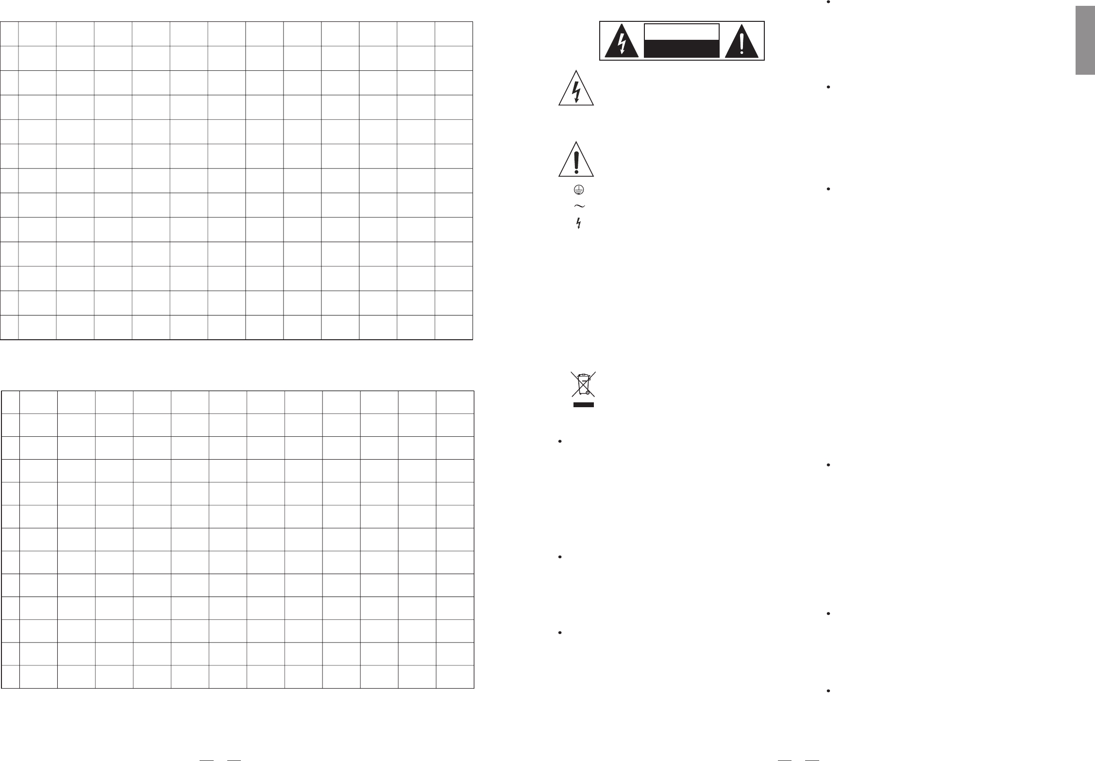
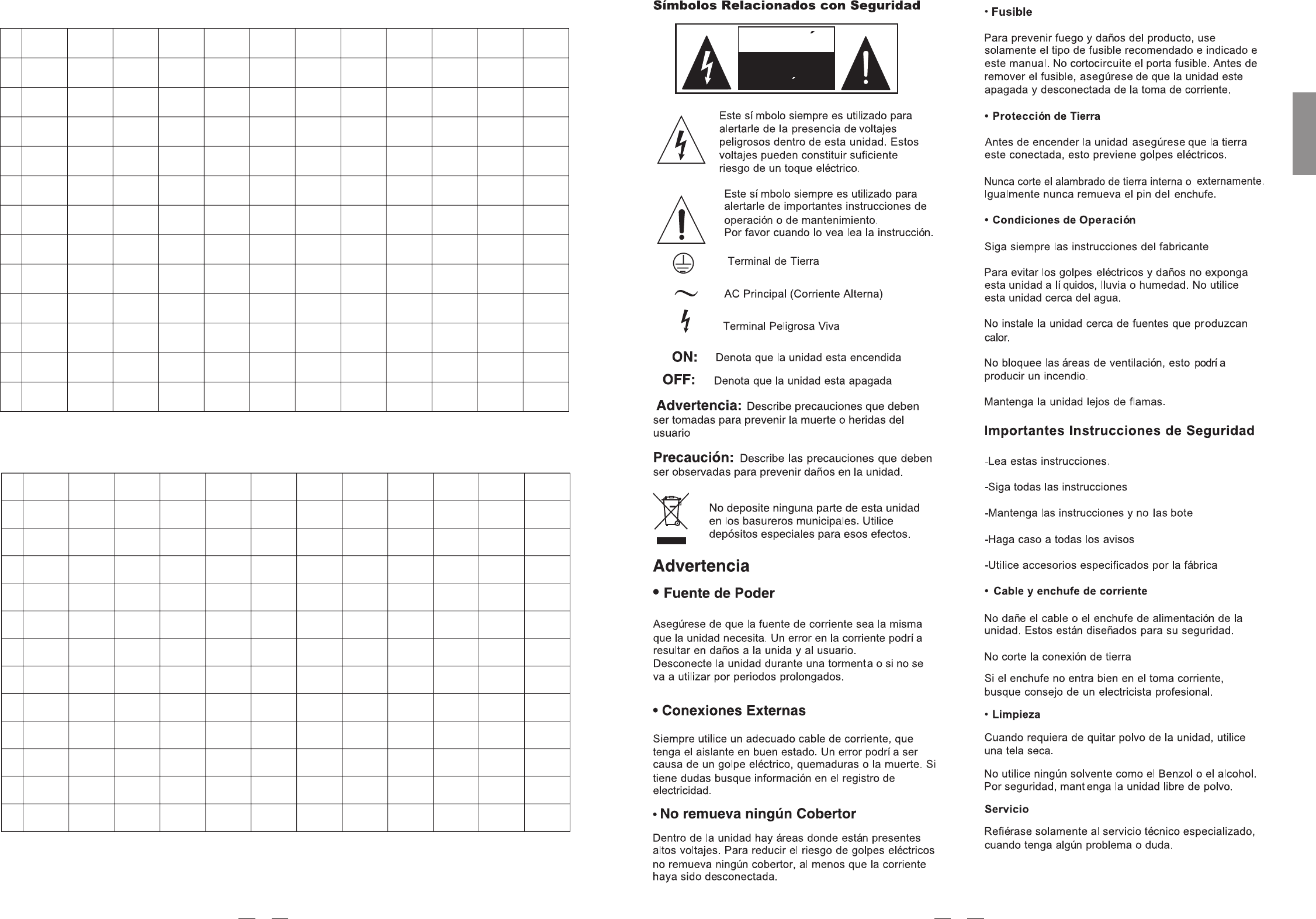
SAFETY RELATED SYMBOLS
CAUTION
RISK OF ELECTRIC SHOCK
DO NOT OPEN
This symbol, wherever used, alerts you to the pre-
sence of un-insulated and dangerous voltages with-
in the product enclosure. These are voltages that
may be sufficient to constitute the risk of electric
shock or death.
Protective Ground Terminal
AC mains (Alternating Current)
Hazardous Live Terminal
ON: Denotes the product is turned on.
This symbol, wherever used, alerts you to impo-
rtant operating and maintenance instructions.
Please read.
OFF: Denotes the product is turned off.
WARNING
Describes precautions that should be observed to
prevent the possibility of death or injury to the user.
CAUTION
Describes precautions that should be observed to
prevent damage to the product.
Protective Ground
Operating Conditions
IMPORTANT SAFETY INSTRUCTIONS
Cleaning
Servicing
Power Cord and Plug
the recommended fuse type as indicated in this
manual. Do not short-circuit the fuse holder. Before
replacing the fuse, make sure that the product is
OFF and disconnected from the AC outlet.
Before turning the product ON, make sure that it is
connected to Ground. This is to prevent the risk of
electric shock.
Never cut internal or external Ground wires. Likewise,
never remove Ground wiring from the Protective
Ground Terminal.
Always install in accordance with the manufacturer's
instructions.
To avoid the risk of electric shock and damage, do
not subject this product to any liquid/rain or moisture.
Do not use this product when in close proximity to
water.
Do not install this product near any direct heat source.
Do not block areas of ventilation. Failure to do so
could result in fire.
Keep product away from naked flames.
Read these instructions
Follow all instructions
Keep these instructions. Do not discard.
Heed all warnings.
Only use attachments/accessories specified by the
manufacturer.
Do not tamper with the power cord or plug. These are
designed for your safety.
Do not remove Ground connections!
If the plug does not fit your AC outlet seek advice from
a qualified electrician.
Protect the power cord and plug from any physical
stress to avoid risk of electric shock.
Do not place heavy objects on the power cord. This
could cause electric shock or fire.
When required, either blow off dust from the product
or use a dry cloth.
Do not use any solvents such as Benzol or Alcohol.
For safety, keep product clean and free from dust.
Refer all servicing to qualified service personnel only.
Do not perform any servicing other than those instruc-
tions contained within the User's Manual.
Fuse
To prevent fire and damage to the product, use only
No user serviceable parts inside.
Power Supply
Ensure that the mains source voltage (AC outlet)
matches the voltage rating of the product. Failure
to do so could result in damage to the product and
possibly the user.
Unplug the product before electrical storms occur
and when unused for long periods of time to reduce
the risk of electric shock or fire.
External Connection
Always use proper ready-made insulated mains
cabling (power cord). Failure to do so could result
in shock/death or fire. If in doubt, seek advice from
a registered electrician.
Do Not Remove Any Covers
Within the product are areas where high voltages
may present. To reduce the risk of electric shock do
not remove any covers unless the AC mains power
cord is removed.
Covers should be removed by qualified service
personnel only.
WARNING
Disposing of this product should not be
placed in municipal waste and should be
Separate collection.
ENGLISH
1
F6: 740.000-764.000(740-769)MHzF6: 740.000-764.000(740-769)MHz
1
2
3
4
5
6
7
8
9
10
11
12
Group1 Group2 Group3 Group4 Group5 Group6 Group7 Group8 Group9 Group10 Group11
Group12
740.125 740.325 740.525 740.725 740.925 741.125 741.325 741.525 741.725 741.925 742.125 742.325
742.525 742.725 742.925 743.125 743.325 743.525 743.725 743.925 744.125 744.325 744.525 744.725
744.925 745.125 745.325 745.525 745.725 745.925 746.125 746.325 746.525 746.725 746.925 747.125
747.325 747.525 747.725 747.925 748.125 748.325 748.525 748.725 748.925 749.125 749.325 749.525
749.725 749.925 750.125 750.325 750.525 750.725 750.925 751.125 751.325 751.525 751.725 751.925
752.125 752.325 752.525 752.725 752.925 753.125 753.325 753.525 753.725 753.925 754.125 754.325
754.525 754.725 754.925 755.125 755.325 755.525 755.725 755.925 756.125 756.325 756.525 756.725
756.925 757.125 757.325 757.525 757.725 757.925 758.125 758.325 758.525 758.725 758.925 759.125
759.325 759.525 759.725 759.925 760.125 760.325 760.525 760.725 760.925 761.125 761.325 761.525
761.725 761.925 762.125 762.325 762.525 762.725 762.925 763.125 763.325 763.525 763.725 763.925
764.125 764.325 764.525 764.725 764.925 765.125 765.325 765.525 765.725 765.925 766.125 766.325
766.525 766.725 766.925 767.125 767.325 767.525 767.725 767.925 768.125 768.325 768.525 768.725
F5: 702.000-726.000(702-731)MHzF5: 702.000-726.000(702-731)MHz
1
2
3
4
5
6
7
8
9
10
11
12
Group1 Group2 Group3 Group4 Group5 Group6 Group7 Group8 Group9 Group10 Group11 Group12
702.125 702.325 702.525 702.725 702.925 703.125 703.325 703.525 703.725 703.925 704.125 704.325
704.525 704.725 704.925 705.125 705.325 705.525 705.725 705.925 706.125 706.325 706.525 706.725
706.925 707.125 707.325 707.525 707.725 707.925 708.125 708.325 708.525 708.725 708.925 709.125
709.325 709.525 709.725 709.925 710.125 710.325 710.525 710.725 710.925 711.125 711.325 711.525
711.725 711.925 712.125 712.325 712.525 712.725 712.925 713.125 713.325 713.525 713.725 713.925
714.125 714.325 714.525 714.725 714.925 715.125 715.325 715.525 715.725 715.925 716.125 716.325
716.525 716.725 716.925 717.125 717.325 717.525 717.725 717.925 718.125 718.325 718.525 718.725
718.925 719.125 719.325 719.525 719.725 719.925 720.125 720.325 720.525 720.725 720.925 721.125
721.325 721.525 721.725 721.925 722.125 722.325 722.525 722.725 722.925 723.125 723.325 723.525
723.725 723.925 724.125 724.325 724.525 724.725 724.925 725.125 725.325 725.525 725.725 725.925
726.125 726.325 726.525 726.725 726.925 727.125 727.325 727.525 727.725 727.925 728.125 728.325
728.525 728.725 728.925 729.125 729.325 729.525 729.725 729.925 730.125 730.325 730.525 730.725
16

TABLE OF CONTENTS
1. .. .
2. ...... ......... . ........... .......................................4
3. .... . .. .... .5
4. ... .. ... ... . ......................................8
5.
INTRODUCTION
FEATURES
CONTROL ELEMENTS
OPERATION
TECHNICAL SPECIFICATIONS
ANNEX
. ............................................................................................................................................3
.... . ..................... ............................................................
........ . ............................................................................................................... .
... .. .. ... ..........................................................................................
......................................................................................................................12
6. ..............................................................................................................................................................13
2
F4: 638.000-662.000(638-664)MHzF4: 638.000-662.000(638-664)MHz
1
Group1 Group2 Group3 Group4 Group5 Group6
638.125 638.325 638.525 638.725 638.925 639.125
639.325 639.525 639.725 639.925 640.125 640.325
640.525 640.725 640.925 641.125 641.325 641.525
641.725 641.925 642.125 642.325 642.525 642.725
642.925 643.125 643.325 643.525 643.725 643.925
644.125 644.325 644.525 644.725 644.925 645.125
645.325 645.525 645.725 645.925 646.125 646.325
646.525 646.725 646.925 647.125 647.325 647.525
647.725 647.925 648.125 648.325 648.525 648.725
648.925 649.125 649.325 649.525 649.725 649.925
650.125 650.325 650.525 650.725 650.925 651.125
651.325 651.525 651.725 651.925 652.125 652.325
2
3
4
5
6
7
8
9
10
11
12
F3: 572.000-596.000(572-598)MHzF3: 572.000-596.000(572-598)MHz
1
2
3
4
5
6
7
8
9
10
11
12
Group1 Group2 Group3 Group4 Group5 Group6
572.125 572.325 572.525 572.725 572.925 573.125
573.325 573.525 573.725 573.925 574.125 574.325
574.525 574.725 574.925 575.125 575.325 575.525
575.725 575.925 576.125 576.325 576.525 576.725
576.925 577.125 577.325 577.525 577.725 577.925
578.125 578.325 578.525 578.725 578.925 579.125
579.325 579.525 579.725 579.925 580.125 580.325
580.525 580.725 580.925 581.125 581.325 581.525
581.725 581.925 582.125 582.325 582.525 582.725
582.925 583.125 583.325 583.525 583.725 583.925
584.125 584.325 584.525 584.725 584.925 585.125
585.325 585.525 585.725 585.925 586.125 586.325
15
SPANISH
This device complies with Part 15 of the FCC Rules.
Operation is subject to the following two conditions:
(1) this device may not cause harmful interference,
and (2) this device must accept any interference received,
including interference that may cause undesired operation.
WARNING: changes or modifications not expressly
approved by the party responsible for compliance could
void the user's authority to operate the equipment.
This equipment has been tested and found to comply with the limits for a Class B
digital device, pursuant to part 15 of the FCC Rules. These limits are designed to
provide reasonable protection against harmful interference in a residential
installation. This equipment generates, uses and can radiate radio frequency energy
and, if not installed and used in accordance with the instructions, may cause harmful
interference to radio communications. However, there is no guarantee that
interference will not occur in a particular installation. If this equipment does cause
harmful interference to radio or television reception, which can be determined by
turning the equipment off and on, the user is encouraged to try to correct the
interference by one or more of the following measures:
—Reorient or relocate the receiving antenna.
—Increase the separation between the equipment and receiver.
—Connect the equipment into an outlet on a circuit different from that to which the
receiver is connected.
—Consult the dealer or an experienced radio/TV technician for help.
1. INTRODUCTION
Thanks for purchasing the TOPP PRO wireless microphone system. The TMW-9144R/T/P series is delicately designed
UHF, PLL synthesized system, with two antennas built inside the receiver for smart switching diversity control, the higher
level RF signals may be fed into the system for greater reliability and coverage, therefore, the risks of breakdown and
interference are effectively reduced.
By the Auto Scan function provided by the TMW-9144, PLL UHF Diversity Receiver, the operating frequency of the
transmitter may be automatically searched out and locked by the system. Or, you can manually adjust the channel
of the transmitter to match the receiver in case you know the operating frequency of it.
Generally, the TMW-9144R/T/P series consists of
TMW-9144R, PLL UHF Diversity Receiver.
TMW-9144T, Handheld transmitter.
TMW-9144P series, Body Pack transmitter.
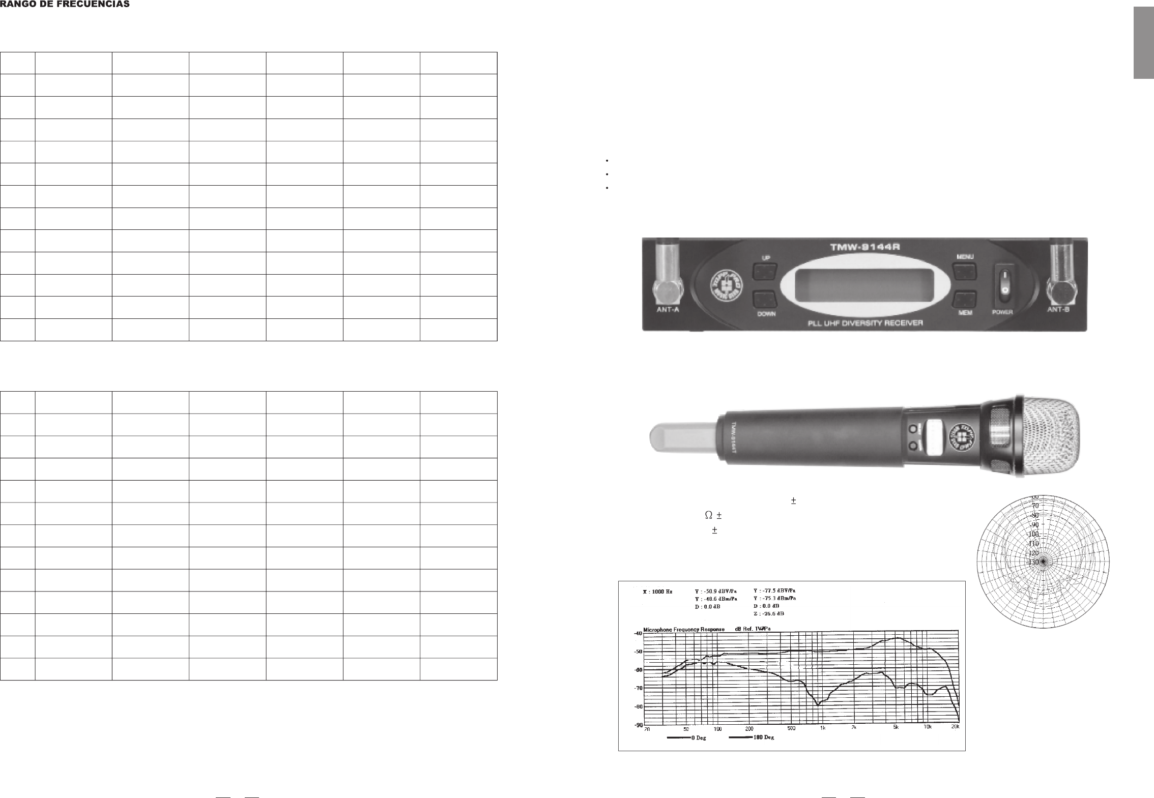
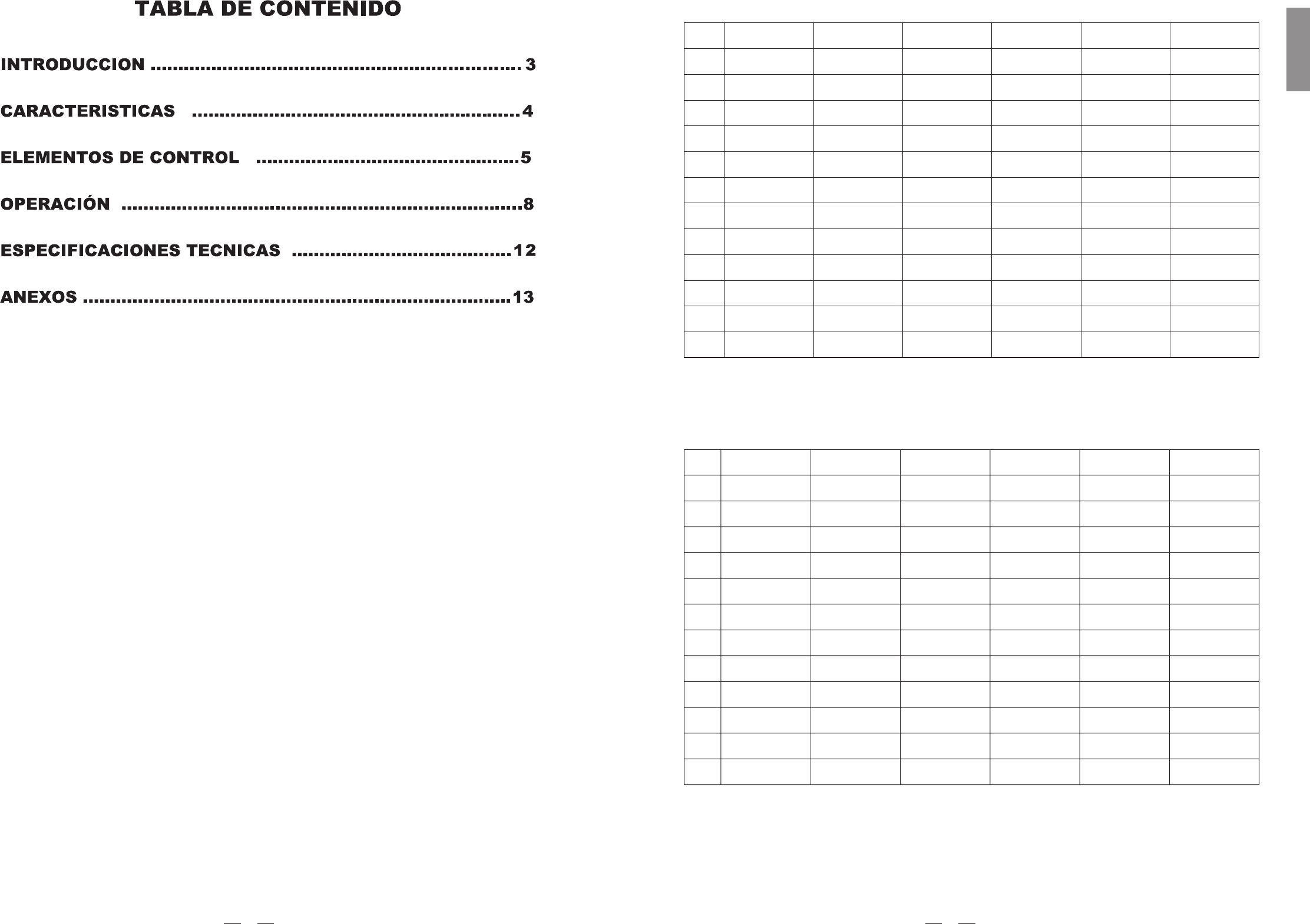
TMW-9144R, PLL UHF Diversity Receiver
TMW-9144T, Handheld transmitter
Type: Dynamic Mic.
Frequency response: 50Hz~16kHz( 3dB)
Impedance: 300 20% at 1kHz
Sensitivity: -71dB 3dB
Direction: Omni-directional
30
60
90
120
330
300
270
240
210
180
150
3
ENGLISH
F1: 470.000-494.000(470-496)MHzF1: 470.000-494.000(470-496)MHz
Group1 Group2 Group3 Group4 Group5 Group6
1
2
3
4
5
6
7
8
9
10
11
12
470.125 470.325 470.525 470.725 470.925 471.125
471.325 471.525 471.725 471.925 472.125 472.325
472.525 472.725 472.925 473.125 473.325 473.525
473.725 473.925 474.125 474.325 474.525 474.725
474.925 475.125 475.325 475.525 475.725 475.925
476.125 476.325 476.525 476.725 476.925 477.125
477.325 477.525 477.725 477.925 478.125 478.325
478.525 478.725 478.925 479.125 479.325 479.525
479.725 479.925 480.125 480.325 480.525 480.725
480.925 481.125 481.325 481.525 481.725 481.925
482.125 482.325 482.525 482.725 482.925 483.125
483.325 483.525 483.725 483.925 484.125 484.325
F2: 518.000-542.000(518-544)MHzF2: 518.000-542.000(518-544)MHz
1
2
3
4
5
6
7
8
9
10
11
12
Group1 Group2 Group3 Group4 Group5 Group6
518.125 518.325 518.525 518.725 518.925 519.125
519.325 519.525 519.725 519.925 520.125 520.325
520.525 520.725 520.925 521.125 521.325 521.525
521.725 521.925 522.125 522.325 522.525 522.725
522.925 523.125 523.325 523.525 523.725 523.925
524.125 524.325 524.525 524.725 524.925 525.125
525.325 525.525 525.725 525.925 526.125 526.325
526.525 526.725 526.925 527.125 527.325 527.525
527.725 527.925 528.125 528.325 528.525 528.725
528.925 529.125 529.325 529.525 529.725 529.925
530.125 530.325 530.525 530.725 530.925 531.125
531.325 531.525 531.725 531.925 532.125 532.325
14
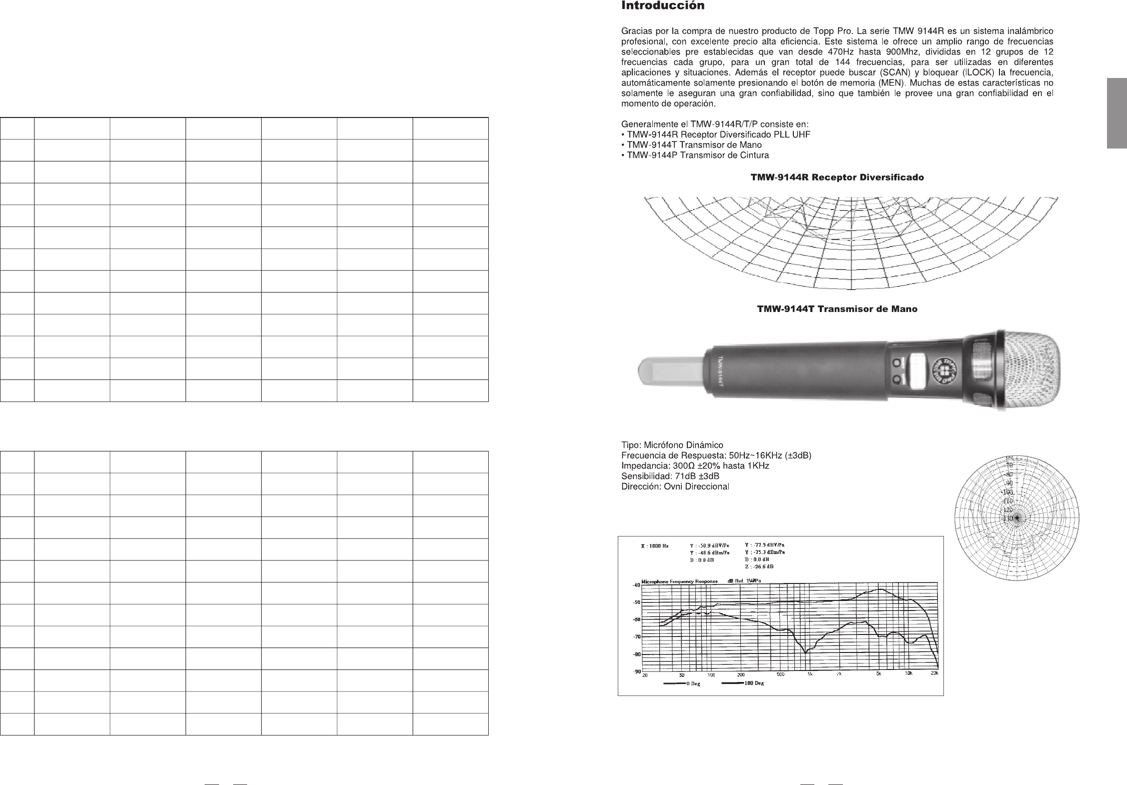
TMW-9144P series, Body Pack transmitter
For the TMW-9144P series, there are several types of clip microphone are please make
sure that the proper microphone has been sound reinforcement system before installation.
included in this product range,
selected for your typical
HM-38, Condenser microphone
Preset impedance: 600ohm;
Freq. response: 80-12KHz;
Sensitivity: -68dB+/-3dB at 1KHz;
Directional: Uni-directional;
Weight: 52g (0.12Ib)
HM-58, Condenser microphone
Preset impedance: 700ohm;
Freq. response: 200-8KHz;
Sensitivity: -65dB at 1KHz;
Directional: Uni-directional;
Weight: 54g (0.12Ib)
Last but not the least, the operating frequency of this wireless system may be varied from 470MHz to900MHz, please refer
to your national EMC regulations to pick out the authorized frequency band (F1 ~ F8, detail please see Annex hereafter) for
your application.
2. FEATURES
TMW-9144R, PLL UHF Diversity Receiver
Friendly interface of front panel LCD status display.
Auto Scan function for easy and convenient operation.
Switching diversity control to receive the RF signal.
Three output levels.
Squelch control.
413
SPANISH
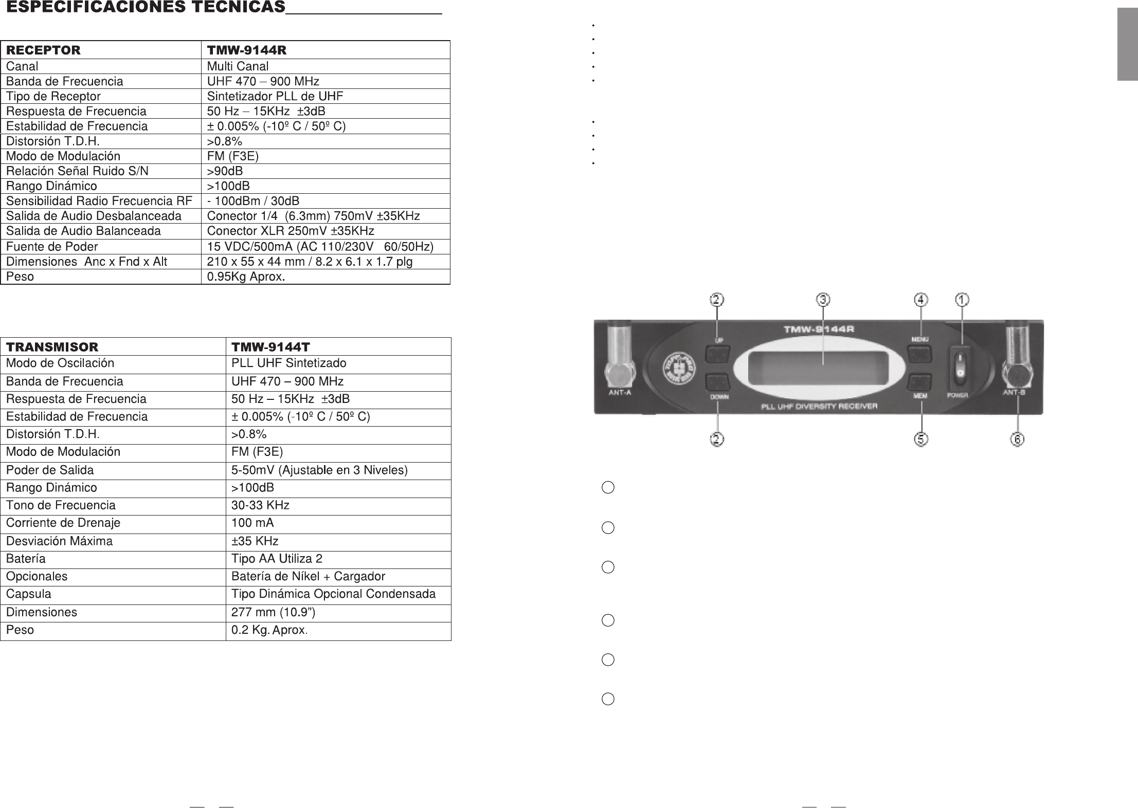
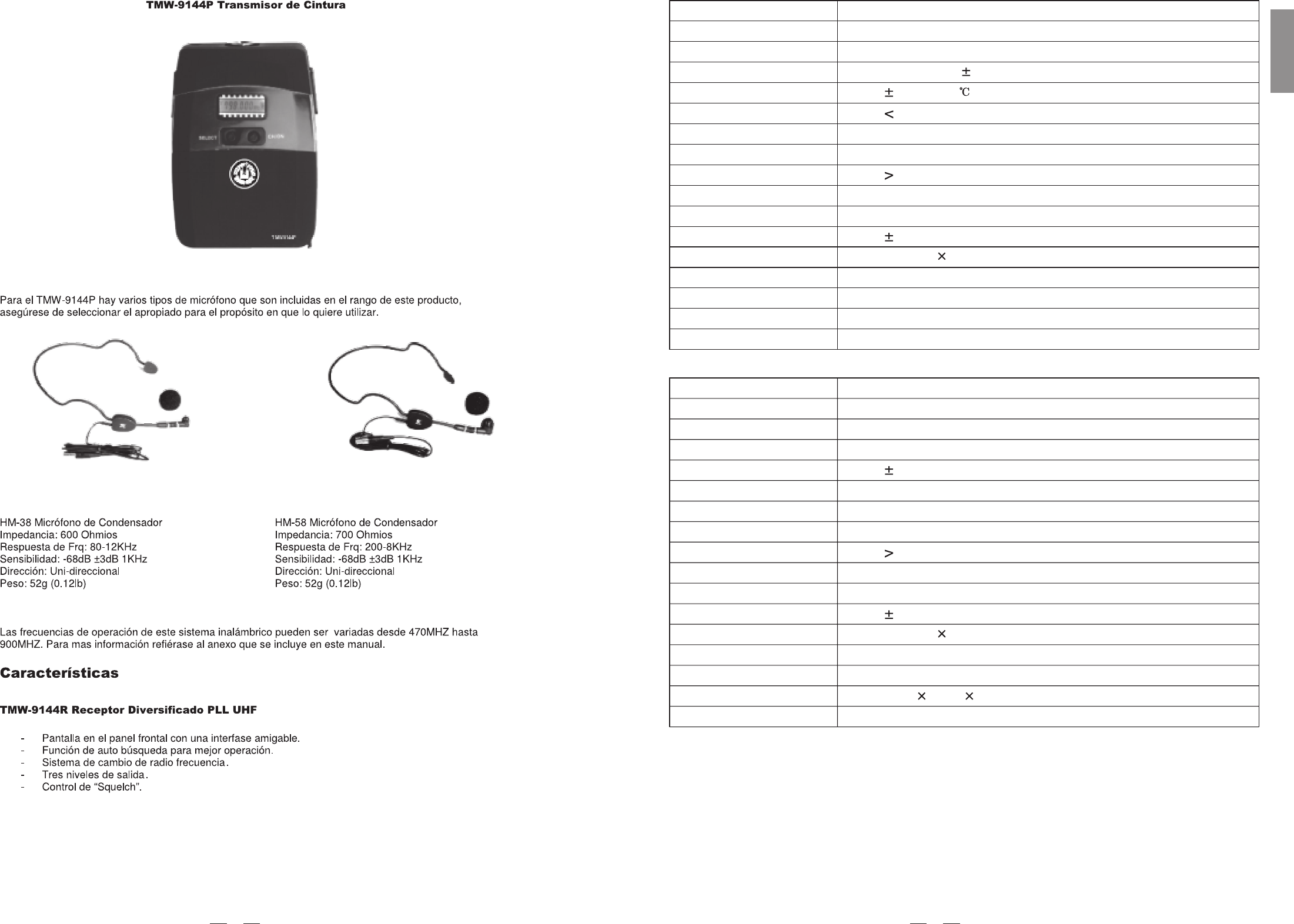
3. CONTROL ELEMENTS
3.1 TMW-9144R, PLL UHF Diversity Receiver
THE FRONT PANEL
Power Switch
It switches on/off TMW-9144R main power.
1
In the menu mode, you can choose the right value via these two keys.
UP/DOWN key
2
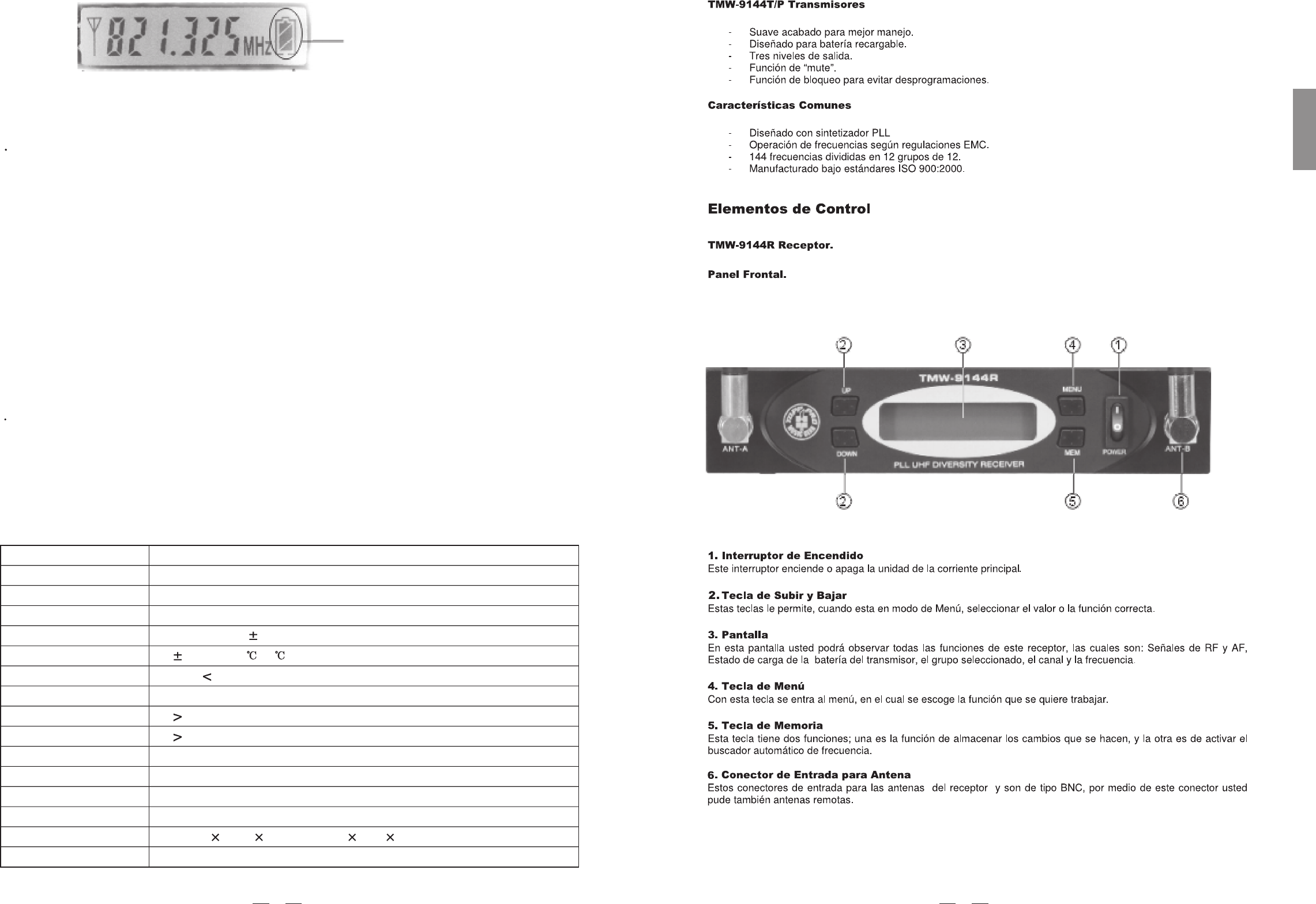
The LCD shows RF/AF signal, remaining battery life of the transmitter, group value, channel value
and the selected frequency.
Display
3
Via this key, you can choose the function you want.
Menu key
4
It is equipped with two functions, memo function, and auto scan function.
MEM key
5
Soft touch painting for comfortable use.
Rechargeable battery design.
Three RF output power levels.
Mute function.
Lock function to avoid the misaction during live applications.
Common features
PLL synthesized design.
Consistent operating frequencies to comply with EMC regulations.
Up to 12x12, total 144 channel frequency presets.
Manufactured under ISO9000:2000, ISO/TS16949:2002 quality management system.
TMW-9144T/P transmitters
5
ENGLISH
Antenna Input Socket
Allows you to connect plug-in antennas, remote antennas, or even a complexantenna network.
6
12
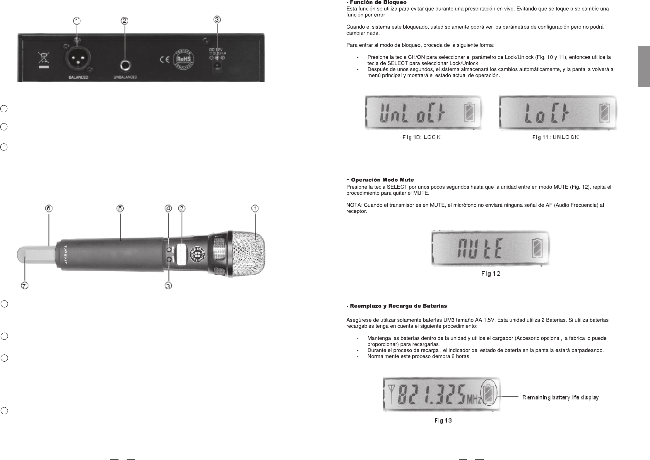
XLR Audio Output
This is a professional balanced XLR output connector.
Audio Output Jack
This is a professional unbalanced output jack.
It is used to connect an attached adapter.
DC Input
3.2 TMW-9144T, Handheld Transmitter
Extremely rugged spring steel mesh grill to protect the capsule underneath in tough stage or live
performances.
Massive Front Grill
Generally, the LCD displays the current operation status.
Keep pressing this key for a few seconds, the unit is powered on or off. After it is switched on,
touch this key slightly to select the parameter which you want to edit,such as the preset channel,
preset group, PL (RF power level), and Lock/unlock; In this mode, if there is no further operation
in the next few seconds, it will return to the main menu, and the LCD displays again the current
preset frequency in MHz, as well as the battery status.
LCD Display
CH/ON Key
THE REAR PANEL
1
2
3
1
2
3
Use this key to edit the parameters in operation mode. Keep pressing this key for a few seconds, the
unit enters into the mute mode, repeat for unmute.
SELECT Key
4
611
SPANISH
Connect the optional recharger(see fig) with this mini jack for battery recharging.
Please make sure that it has rechargeable batteries inside before plugging in the
recharger with the mini charge jack.
Charge Jack
6
The antenna is integrated into the transmitter body; to get effective RF transmission, never cover the antenna
with hand, etc.
Antenna
7
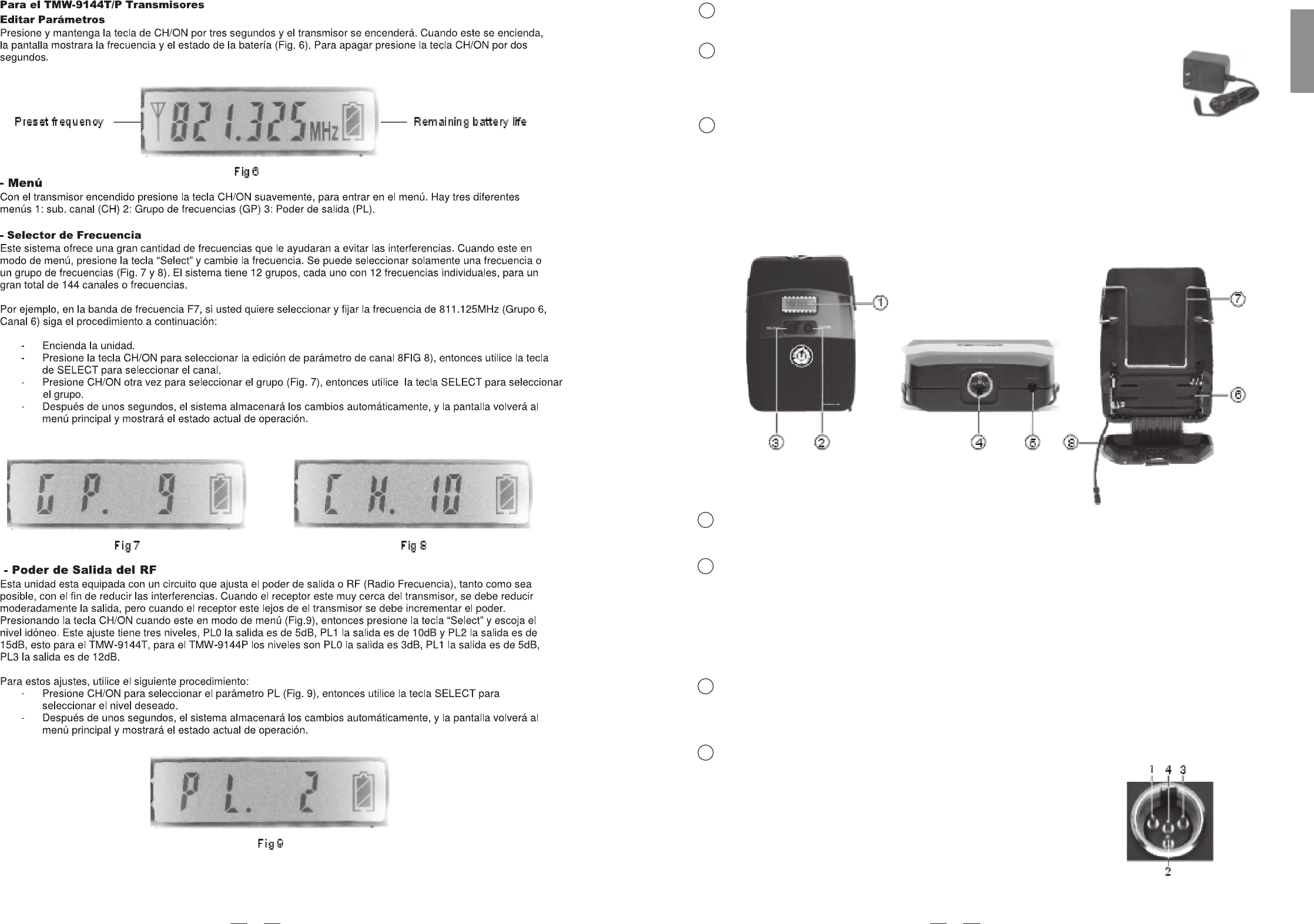
3.3 TMW-9144P series, Body Pack Transmitter
CH/ON Key
Keep pressing this key for a few seconds, the unit will be powered on or off. After it is switched on, touch this
key slightly to select the parameter which you want to edit, such as the preset channel, preset group, PL(RF
power level) and Lock/unlock. In this mode, if there is no further operation in the next few seconds, it will
return to the main menu, and the LCD displays again the current preset frequency in MHz, as well as the
battery status.
SELECT Key
Use this key to edit the parameters in operation mode. Keep pressing this key for a few seconds, the unit will
enter into the mute mode, repeat for unmute.
2
3
1
LCD Display
Generally, the LCD displays the current operation status.
4
Mini 4P connector
This connector is used to connect the unit with the clip microphones,
for example, HM-38 or HM-58 condenser microphones.
The unit may be powered from a dry or rechargeable battery.
Battery Compartment
5
Pin 2, GND
Pin 4, for Dynamic or condenser microphone
7
ENGLISH
Pin 3, Phantom power supply for Condenser microphone
Pin 1, for Guitar, bass and keyboards
10
Antenna
It is a flexible antenna. To get effective transmission, never cover the antenna hand, clothes, etc during
operation, and always position the transmitter receiver.
with
nearby the
8
Charge Jack
With the rechargeable batteries inside, use the charger (optional accessory, provided by the manufacturer)
to recharge the batteries. For detail operation, please refer to chapter 4.2.3, Battery replacing and charging.
5
Battery Compartment
This unit may be powered from one pair of dry or rechargeable batteries, UM3 size AA 1.5V.
6
Belt clip
It is the detachable belt clip for easy carry during live applications.
7
4. OPERATION
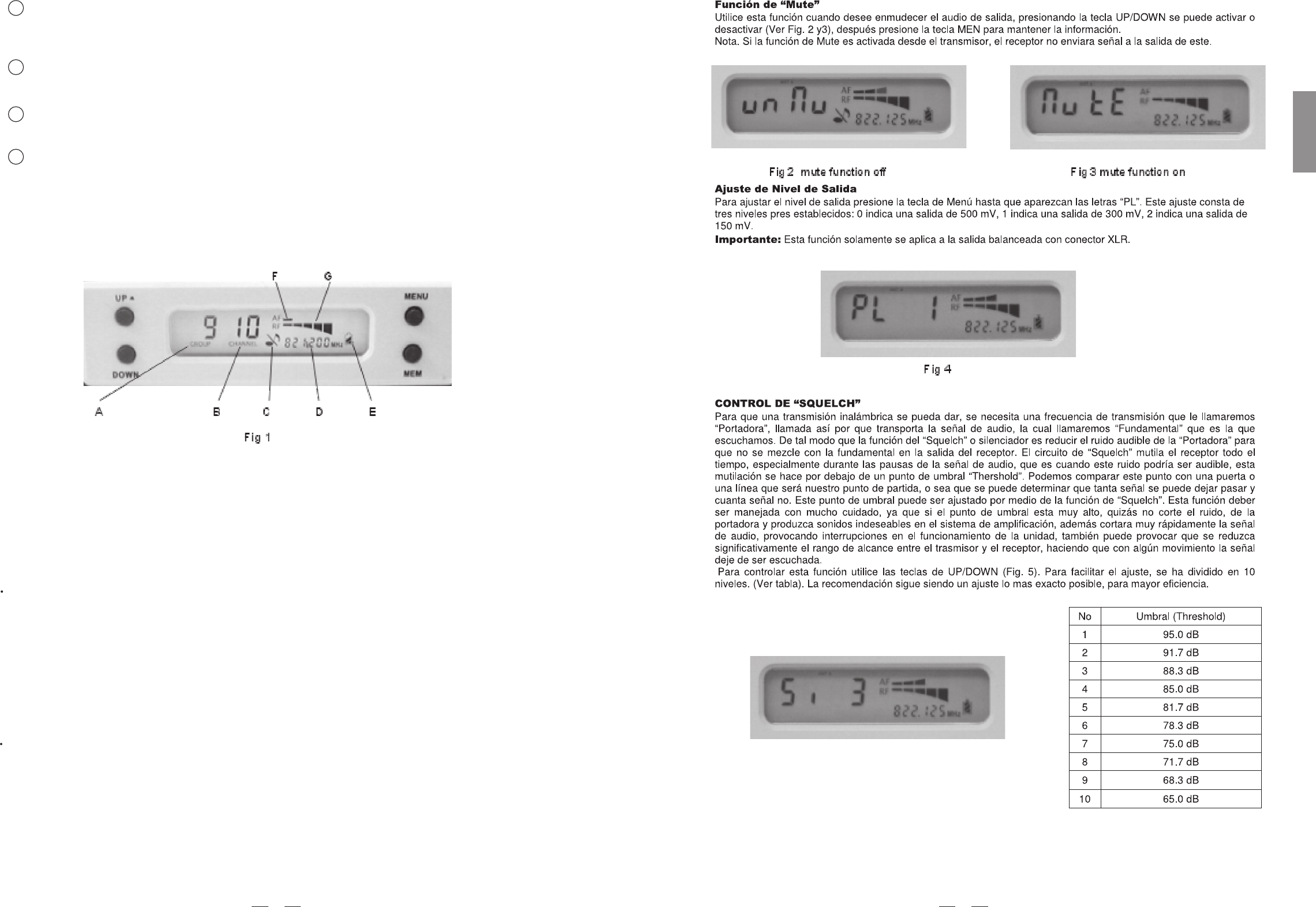
A: Frequency group.
B: Subchannel.
C: Mute(if the mute function is engaged, the mute label is shown, if not , the label disappears).
D: The selected frequency.
E: Remaining battery life of transmitter.
F: Audio bar graph indicating the receiver audio level.
G: RF bar graph indicating the field strength of the received signal.
4.1 For the TMW-9144R, PLL UHF Diversity Receiver
Auto Scan
When the receiver is powered on, press and hold the MEM key for one second, receiver is in auto scanning.the
The scan function automatically searches the frequency band from start to stop. During the search,receiver's entire
the indicates the frequencies in MHz as they areaudio output is muted and the display scanned. As soon as the
correct frequency is reached, , the value of frequency will be flashing, pressthe scan will be stopped automatically
the MEM key, the information.you can save
Remark: some frequencies should be scanned manually by adjusting UP/DOWN pleasekey, refer to Annex
for details!
Manually Selecting Frequency
Press the MENU button, "GROUP" is flashing, you can choose the right frequency you need via the UP/ DOWNgroup
button, when the frequency group is set, please MEM button to store the information. Press the MENU button twopress
times, is flashing, you can choose the right subchannel you need via the when the"CHANNEL" UP/DOWN button,
subchannel you need is set, please press the MEM button to save it.
8 9
SPANISH
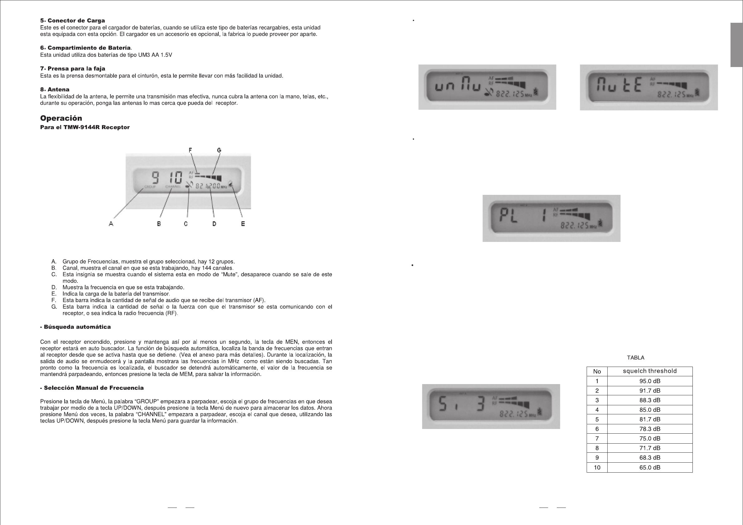
Fig 3 mute function onFig 2 mute function off
Output Level Adjusting
In output level adjusting mode(see fig 4), use the SELECT button to adjust the output level. The output level
has 3 choices, 0 indicates the output level is 500mV, 1 indicates the output level is 300mV, 2 indicates the
output level is 150mV.
Fig 4
Note: the function is only applied to the level of Balanced output.
Squelch Control
Fig 5
Mute Function
In mute mode, use UP/DOWN key to on/off the mute function.(fig 2 mute function off, fig 3: mute function on),:
press the MEM button to keep the information. Note: when the transmitter is muted, no audio signal will be sent
out from the receiver.
9
ENGLISH
The job of a squelch circuit is to reduce audible noise. It eliminates noise during pauses in the audio signal by
muting the receiver every time the audio level drops below a defined threshold. The squelch control on the receiver
sets this threshold. Use the squelch control with care! If the squelch threshold is too high, the squelch will not only
cut out noise but mute quiet audio signals as well because the squelch responds to the detected voltage and cannot
distinguish between wanted signal and noise. Besides that, a too high squelch threshold also decreases the usable
range. In the squelch control mode(fig 5), use the UP/DOWN key to select squelch threshold. In order to achieve
easy operation, the squelch threshold is divided into10 levels, please refer to table.
8
Fig 1
4.2 For the TMW-9144T/P series transmitters,
4.2.1 Edit The Parameter
Press and hold the CH/ON key for a few seconds, then the transmitter is powered on. Now, the LCD displays the
current operation status:
Fig 7 Fig 8
Frequency select
It is a multi-channels PLL synthesized system. In practice, to effectively avoid the interference from
any lighting equipment, computers, fax machines, etc nearby, it is usually advised to switch to another frequency
to get best performance.
After the transmitter is switched on, touch the CH/ON key slightly to select the parameter which you want to
edit, such as the preset channel, preset group, PL (RF power level), and Lock/unlock.
The frequency range of this system is UHF, 470MHz ~ 900MHz, and it is divided into 8 frequency bands (F1 ~ F8)
according to the country's EMC regulations; For each frequency band, to select the proper frequency preset, please
first pick the right Group, then the Channel; For details please refer to the Annex.specify
For example, in F7 frequency band, if you want to select the frequency preset of 811.125MHz (Group 6, Channel 6),
please follow the below procedure.
Touch the CH/ON key slightly again to select the edited parameter of Group (refer to Fig 7), then use the SELECT
key to specify the proper Group.
Several seconds later after that, the system stores the settings automatically, and LCD display comes back to
the main menu which shows the current operation status.
Turn on the unit first.
Touch the CH/ON key slightly to select the edited parameter of Channel (refer to Fig 8), then use the SELECT
key to specify the proper channel.
RF Output Power Select
Three different RF output power levels are available of TMW-9144T
PL 0, the output power is 5dBm; PL 1, the output power is 10dBm; PL 2, the output power is 15dBm.
But, It's a different from TMW-9144P
PL 0, the output power is 3dBm; PL 1, the output power is 5dBm; PL 2, the output power is 12dBm.
Please follow the below procedure to select the proper RF output power
Touch the CH/ON key slightly to select the edited parameter of PL (refer to Fig 9), then use the SELECT key to specify
the proper RF output Power version.
Several seconds later after that, the system stores the settings automatically, and LCD display comes back to the main
menu which shows the current operation status.
10 7
SPANISH
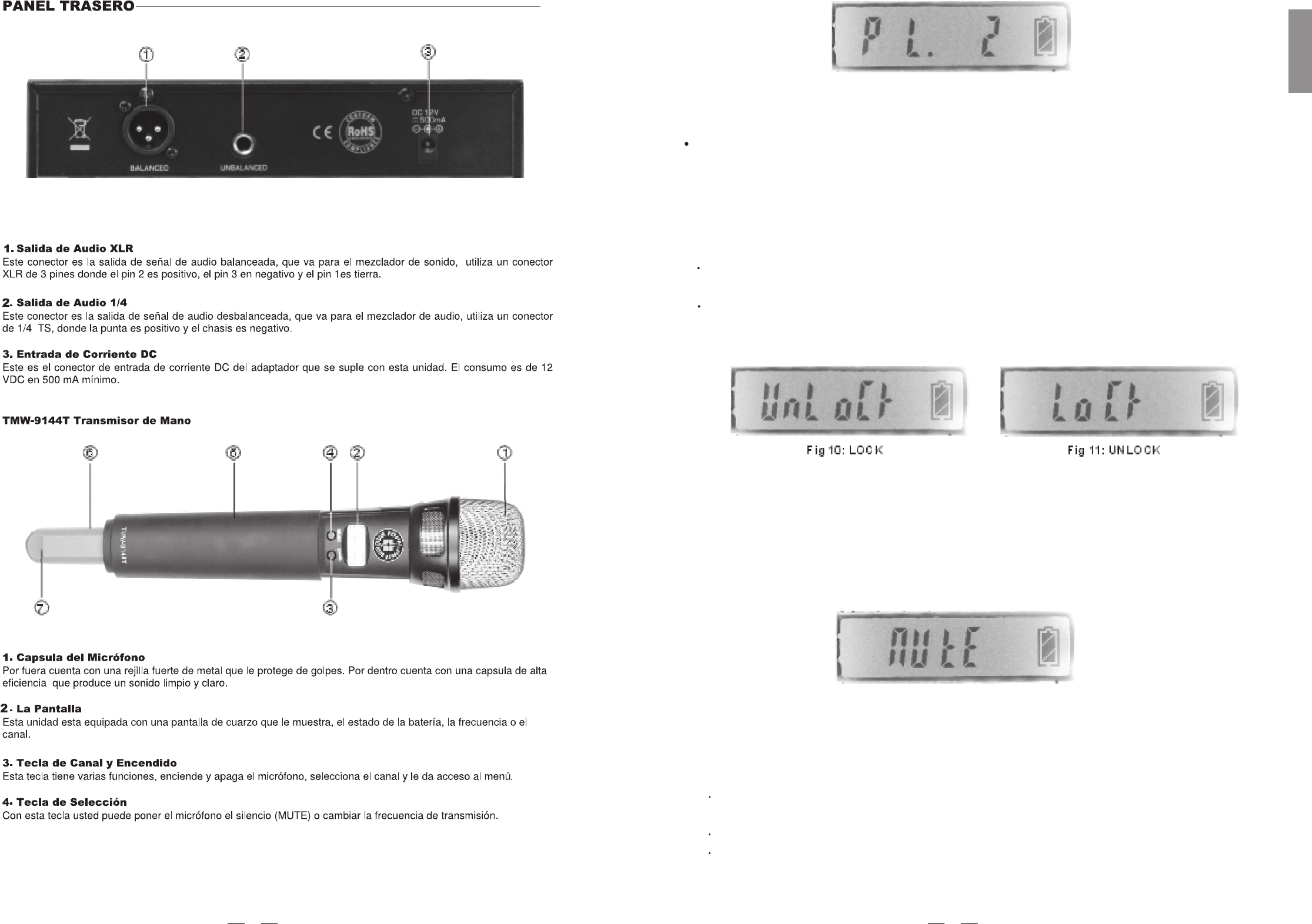
Fig 9
Since the CH/ON and SELECT keys may be easily activated by simple touch, to avoid any mis-action during the
live application, the Lock/Unlock is provided by this system for touch-proof under the Locked situation.
In case the system is locked, you can still use the CH/ON key to select the edited parameters, but, except for the
Lock/Unlock, others can't be edited.
LOCK Function
To enter into the Lock mode, please follow the below procedure.
Touch the CH/ON key slightly to select the edited parameter of Lock/Unlock (refer to then use theFig 10 & 11),
SELECT key to specify Lock or Unlock.
Several seconds later after that, the system stores the settings automatically, and LCD comesdisplay
back to the main menu which shows the current operation status.
4.2.2 Mute Mode Operation
Fig 12
Keep pressing the SELECT key for a few seconds, the unit will enter into the mute mode (see the fig 12),
repeat for unmute.
Note: when the transmitter is muted, the microphone will not send out any AF signal, that means, no sound has
been sent out from the microphone.
4.2.3 Battery Replacing And Charging
Please be advised to use only UM3 size AA 1.5V, one pair batteries for power supply. If the rechargeable batteries
are used.
Please keep the batteries inside, and use the charger (optional accessory, provided by the manufacturer) to
recharge the batteries.
During the charging process, the "Remaining battery life display" flashes.
Normally, the battery should be recharged within 6 hours.
Caution: Danger of explosion if battery is incorrectly replaced. Replace only with the same or equivalent type.
11
ENGLISH
6
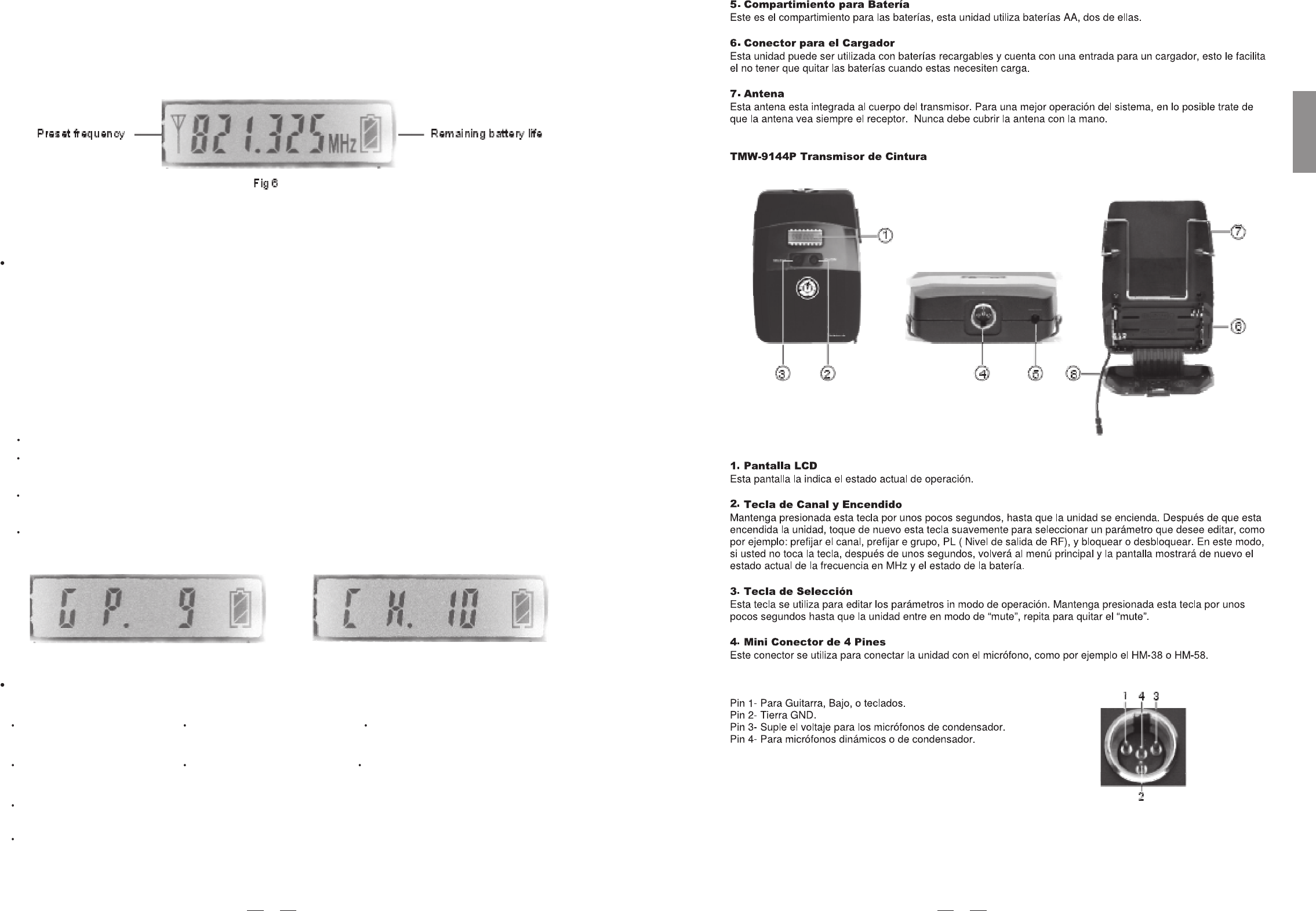
Remaining battery life display
Fig 13
4.3 Operating frequency matches between the receiver and the transmitter
To make the operating frequency match between the transmitter and the receiver, there are two options.
Controlled from the receiver, TMW-9144R
1) Auto Scan
Turn on the receiver, the MEM key . You can see"SCAN"press for a few seconds to enter into the auto scan mode
flashes on the top left of the LCD, it means the auto scan function has been activated. under the auto scan mode,
the scan function automatically searches the receiver's entire frequency band from start to stop. During the search,
these presets of GROUP, CHANNEL and frequency keep flashing as they are scanned. As soon as he correct
frequency is reached, the scan will be stopped automatically, the value of frequency will be flashing channel preset,
press the MEM key, you can save the information.
Adjust from the transmitter,
1) Check the preset frequency (preset group, and preset channel) displayed
2) Switch on the transmitter.
3) Touch the CH/ON key slightly to select the parameters to be edited.
4) Use the Select key to set the proper channel / group.
on the receiver in MHz.
2) Manually Selecting Frequency
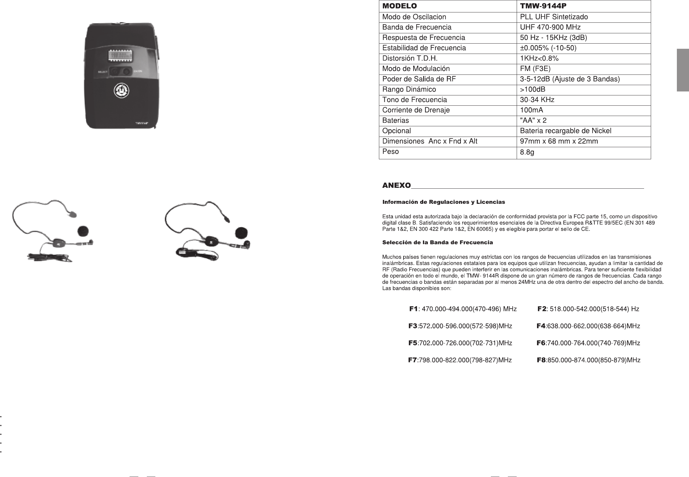
MODEL
Channel
Frequency band
Receiver type
Frequency response
Frequency stability
T.H.D.
Modulation mode
S/N Ratio
Dynamic
RF sensitivity
Audio output
Balance output
Power supply
TMW-9144R
Multi-channels, up to 144 frequency presets for each frequency bands
UHF 470-900 MHz Dependent on applicable country regulations
PLL UHF SYNTHESIZED
50 Hz-15KHz ( 3dB)
0.005% (-10 -50 )
1KHZ 0.8%
FM (F3E)
90dB
100dB
-100 dBm/30dB SINAD
Unbalanced 6.3mm phone jack 550mV 20KHz deviation
1V , 20KHz deviation
DC 15V/ 500mA (AC 110V/230V 50/60Hz adaptor)
5. TECHNICAL SPECIFICATIONS
210(W) 55 (D) 44(H)mm; (8.2" 6.1" 1.7")
Approx. 0.95kg
Weight
Dimensions
12
Remark: some frequencies should be scanned manually by adjusting UP/DOWN Key, please refer to user's
manual of TMW-9144R for details!
Turn on the receiver. After touch the MENU key, the 'Group' indicated on the LCD display flashes, and use the
UP/DOWN key to select the right group, after it is done, press 'Mem' to store the settings. To edit the preset
channel or other parameters, please press again the MENU key, and so on.
5
SPANISH
MODEL
Oscillation mode
Carrier frequency band
Frequency response
Frequency stability
T.H.D.
Modulation mode
RF output power
Dynamic
Tone frequency
Current drain
Max. Deviation
Battery
Optional
Mic. Capsule(optional)
Dimensions
Weight
MODEL
Oscillation mode
Carrier frequency band
Frequency response
Frequency stability
T.H.D.
Modulation mode
RF output power
Dynamic
Tone frequency
Current drain
Max. Deviation
Battery
Optional
Mic. Capsule(optional)
Dimensions
Weight
TMW-9144T
PLL UHF SYNTHESIZED
UHF 470-900 MHz Dependent on applicable country regulations
50 Hz-15KHz ( 3dB)
0.005% (-10 ~ 50)
0.8%
FM (F3E)
5-50mW(adjustable 3 bands)
100dB
30-33 KHz
100mA
35KHz
"AA" type 2
Nickel hydrogen battery +charger
Condenser or Dynamic Capsule
277 mm (10.9")
Approx.0.2kg
TMW-9144P
PLL UHF SYNTHESIZED
UHF 470-900 MHz Dependent on applicable country regulations
50 Hz-15KHz ( 3dB)
0.005% (-10~ 50)
1KHz<0.8%
FM (F3E)
3-5-12db(adjustable 3 bands)
100dB
30-34 KHz
100mA
35KHz
"AA" type 2
Nickel hydrogen battery +charger
Condenser or Dynamic Capsule
8.8g
97mm 68mm 22mm
6. ANNEX
Most countries closely regulate the radio frequencies used in the transmission of wireless information. These
regulations state which devices can use which frequencies, and help to limit the amount of RF(radio frequency)
interference in all wireless communications.To be flexible enough to operate worldwide, TMW-9144R Wireless
receivers are available in a number of models, each with a unique frequency range. Each frequency range, or
band, spans up to 24MHz of the wireless broadcast spectrum. Available bands are:
6.1 Frequency Band Selection
13
ENGLISH
4
F1:470.000-494.000(470-496)MHz F2:518.000-542.000(518-544)MHz
F3:572.000-596.000(572-598)MHz F4:638.000-662.000(638-664)MHz
F5:702.000-726.000(702-731)MHz F6:740.000-764.000(740-769)MHz
F7:798.000-822.000(798-827)MHz F8:850.000-874.000(850-879)MHz
6.2 Frequency Ranges
14
F1: 470.000-494.000(470-496)MHzF1: 470.000-494.000(470-496)MHz
Group1 Group2 Group3 Group4 Group5 Group6
1
2
3
4
5
6
7
8
9
10
11
12
470.125 470.325 470.525 470.725 470.925 471.125
471.325 471.525 471.725 471.925 472.125 472.325
472.525 472.725 472.925 473.125 473.325 473.525
473.725 473.925 474.125 474.325 474.525 474.725
474.925 475.125 475.325 475.525 475.725 475.925
476.125 476.325 476.525 476.725 476.925 477.125
477.325 477.525 477.725 477.925 478.125 478.325
478.525 478.725 478.925 479.125 479.325 479.525
479.725 479.925 480.125 480.325 480.525 480.725
480.925 481.125 481.325 481.525 481.725 481.925
482.125 482.325 482.525 482.725 482.925 483.125
483.325 483.525 483.725 483.925 484.125 484.325
F2: 518.000-542.000(518-544)MHzF2: 518.000-542.000(518-544)MHz
1
2
3
4
5
6
7
8
9
10
11
12
Group1 Group2 Group3 Group4 Group5 Group6
518.125 518.325 518.525 518.725 518.925 519.125
519.325 519.525 519.725 519.925 520.125 520.325
520.525 520.725 520.925 521.125 521.325 521.525
521.725 521.925 522.125 522.325 522.525 522.725
522.925 523.125 523.325 523.525 523.725 523.925
524.125 524.325 524.525 524.725 524.925 525.125
525.325 525.525 525.725 525.925 526.125 526.325
526.525 526.725 526.925 527.125 527.325 527.525
527.725 527.925 528.125 528.325 528.525 528.725
528.925 529.125 529.325 529.525 529.725 529.925
530.125 530.325 530.525 530.725 530.925 531.125
531.325 531.525 531.725 531.925 532.125 532.325
3
30
60
90
120
330
300
270
240
210
180
150
SPANISH
F4: 638.000-662.000(638-664)MHzF4: 638.000-662.000(638-664)MHz
1
Group1 Group2 Group3 Group4 Group5 Group6
638.125 638.325 638.525 638.725 638.925 639.125
639.325 639.525 639.725 639.925 640.125 640.325
640.525 640.725 640.925 641.125 641.325 641.525
641.725 641.925 642.125 642.325 642.525 642.725
642.925 643.125 643.325 643.525 643.725 643.925
644.125 644.325 644.525 644.725 644.925 645.125
645.325 645.525 645.725 645.925 646.125 646.325
646.525 646.725 646.925 647.125 647.325 647.525
647.725 647.925 648.125 648.325 648.525 648.725
648.925 649.125 649.325 649.525 649.725 649.925
650.125 650.325 650.525 650.725 650.925 651.125
651.325 651.525 651.725 651.925 652.125 652.325
2
3
4
5
6
7
8
9
10
11
12
F3: 572.000-596.000(572-598)MHzF3: 572.000-596.000(572-598)MHz
1
2
3
4
5
6
7
8
9
10
11
12
Group1 Group2 Group3 Group4 Group5 Group6
572.125 572.325 572.525 572.725 572.925 573.125
573.325 573.525 573.725 573.925 574.125 574.325
574.525 574.725 574.925 575.125 575.325 575.525
575.725 575.925 576.125 576.325 576.525 576.725
576.925 577.125 577.325 577.525 577.725 577.925
578.125 578.325 578.525 578.725 578.925 579.125
579.325 579.525 579.725 579.925 580.125 580.325
580.525 580.725 580.925 581.125 581.325 581.525
581.725 581.925 582.125 582.325 582.525 582.725
582.925 583.125 583.325 583.525 583.725 583.925
584.125 584.325 584.525 584.725 584.925 585.125
585.325 585.525 585.725 585.925 586.125 586.325
15
ENGLISH
2
F6: 740.000-764.000(740-769)MHzF6: 740.000-764.000(740-769)MHz
1
2
3
4
5
6
7
8
9
10
11
12
Group1 Group2 Group3 Group4 Group5 Group6 Group7 Group8 Group9 Group10 Group11
Group12
740.125 740.325 740.525 740.725 740.925 741.125 741.325 741.525 741.725 741.925 742.125 742.325
742.525 742.725 742.925 743.125 743.325 743.525 743.725 743.925 744.125 744.325 744.525 744.725
744.925 745.125 745.325 745.525 745.725 745.925 746.125 746.325 746.525 746.725 746.925 747.125
747.325 747.525 747.725 747.925 748.125 748.325 748.525 748.725 748.925 749.125 749.325 749.525
749.725 749.925 750.125 750.325 750.525 750.725 750.925 751.125 751.325 751.525 751.725 751.925
752.125 752.325 752.525 752.725 752.925 753.125 753.325 753.525 753.725 753.925 754.125 754.325
754.525 754.725 754.925 755.125 755.325 755.525 755.725 755.925 756.125 756.325 756.525 756.725
756.925 757.125 757.325 757.525 757.725 757.925 758.125 758.325 758.525 758.725 758.925 759.125
759.325 759.525 759.725 759.925 760.125 760.325 760.525 760.725 760.925 761.125 761.325 761.525
761.725 761.925 762.125 762.325 762.525 762.725 762.925 763.125 763.325 763.525 763.725 763.925
764.125 764.325 764.525 764.725 764.925 765.125 765.325 765.525 765.725 765.925 766.125 766.325
766.525 766.725 766.925 767.125 767.325 767.525 767.725 767.925 768.125 768.325 768.525 768.725
F5: 702.000-726.000(702-731)MHzF5: 702.000-726.000(702-731)MHz
1
2
3
4
5
6
7
8
9
10
11
12
Group1 Group2 Group3 Group4 Group5 Group6 Group7 Group8 Group9 Group10 Group11 Group12
702.125 702.325 702.525 702.725 702.925 703.125 703.325 703.525 703.725 703.925 704.125 704.325
704.525 704.725 704.925 705.125 705.325 705.525 705.725 705.925 706.125 706.325 706.525 706.725
706.925 707.125 707.325 707.525 707.725 707.925 708.125 708.325 708.525 708.725 708.925 709.125
709.325 709.525 709.725 709.925 710.125 710.325 710.525 710.725 710.925 711.125 711.325 711.525
711.725 711.925 712.125 712.325 712.525 712.725 712.925 713.125 713.325 713.525 713.725 713.925
714.125 714.325 714.525 714.725 714.925 715.125 715.325 715.525 715.725 715.925 716.125 716.325
716.525 716.725 716.925 717.125 717.325 717.525 717.725 717.925 718.125 718.325 718.525 718.725
718.925 719.125 719.325 719.525 719.725 719.925 720.125 720.325 720.525 720.725 720.925 721.125
721.325 721.525 721.725 721.925 722.125 722.325 722.525 722.725 722.925 723.125 723.325 723.525
723.725 723.925 724.125 724.325 724.525 724.725 724.925 725.125 725.325 725.525 725.725 725.925
726.125 726.325 726.525 726.725 726.925 727.125 727.325 727.525 727.725 727.925 728.125 728.325
728.525 728.725 728.925 729.125 729.325 729.525 729.725 729.925 730.125 730.325 730.525 730.725
16
PRECAUCION
NO ABRIR,
PELIGRO DE
GOLPE ELECTRICO
1
SPANISH
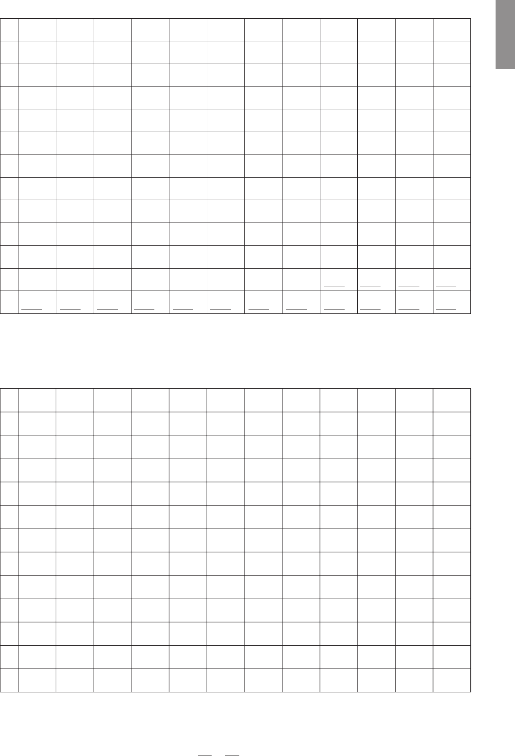
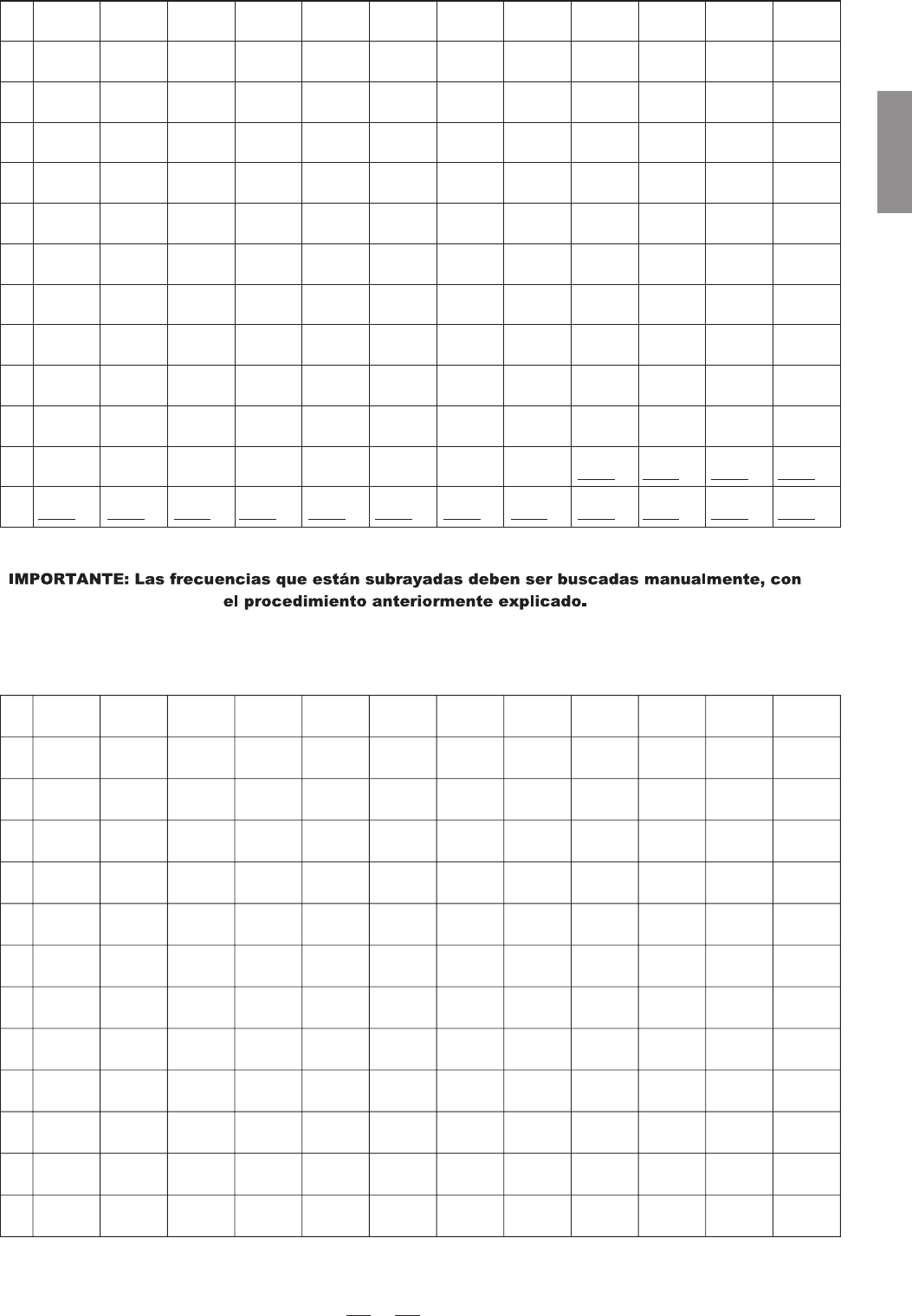
F7: 798.000-822.000(798-827)MHzF7: 798.000-822.000(798-827)MHz
1
2
3
4
5
6
7
8
9
10
11
12
Group1 Group2 Group3 Group4 Group5 Group6 Group7 Group8 Group9 Group10
Group11
Group12
798.125 798.325 798.525 798.725 798.925 799.125 799.325 799.525 799.725 799.925 800.125 800.325
800.525 800.725 800.925 801.125 801.325 801.525 801.725 801.925 802.125 802.325 802.525 802.725
802.925 803.125 803.325 803.525 803.725 803.925 804.125 804.325 804.525 804.725 804.925 805.125
805.325 805.525 805.725 805.925 806.125 806.325 806.525 806.725 806.925 807.125 807.325 807.525
807.725 807.925 808.125 808.325 808.525 808.725 808.925 809.125 809.325 809.525 809.725 809.925
810.125 810.325 810.525 810.725 810.925 811.125 811.325 811.525 811.725 811.925 812.125 812.325
812.525 812.725 812.925 813.125 813.325 813.525 813.725 813.925 814.125 814.325 814.525 814.725
814.925 815.125 815.325 815.525 815.725 815.925 816.125 816.325 816.525 816.725 816.925 817.125
817.325 817.525 817.725 817.925 818.125 818.325 818.525 818.725 818.925 819.125 819.325 819.525
819.725 819.925 820.125 820.325 820.525 820.725 820.925 821.125 821.325 821.525 821.725 821.925
822.125 822.325 822.525 822.725 822.925 823.125 823.325 823.525 823.725 823.925 824.125 824.325
824.525 824.725 824.925 825.125 825.325 825.525 825.725 825.925 826.125 826.325 826.525 826.725
F8: 850.000-874.000(850-879)MHzF8: 850.000-874.000(850-879)MHz
1
2
3
4
5
6
7
8
9
10
11
12
Group1 Group2 Group3 Group4 Group5 Group6 Group7 Group8 Group9 Group10 Group11
Group12
850.125 850.325 850.525 850.725 850.925 851.125 851.325 851.525 851.725 851.925 852.125 852.325
852.525 852.725 852.925 853.125 853.325 853.525 853.725 853.925 854.125 854.325 854.525 854.725
854.925 855.125 855.325 855.525 855.725 855.925 856.125 856.325 856.525 856.725 856.925 857.125
857.325 857.525 857.725 857.925 858.125 858.325 858.525 858.725 858.925 859.125 859.325 859.525
859.725 859.925 860.125 860.325 860.525 860.725 860.925 861.125 861.325 861.525 861.725 861.925
862.125 862.325 862.525 862.725 862.925 863.125 863.325 863.525 863.725 863.925 864.125 864.325
864.525 864.725 864.925 865.125 865.325 865.525 865.725 865.925 866.125 866.325 866.525 866.725
866.925 867.125 867.325 867.525 867.725 867.925 868.125 868.325 868.525 868.725 868.925 869.125
869.325 869.525 869.725 869.925 870.125 870.325 870.525 870.725 870.925 871.125 871.325 871.525
871.725 871.925 872.125 872.325 872.525 872.725 872.925 873.125 873.325 873.525 873.725 873.925
874.125 874.325 874.525 874.725 874.925 875.125 875.325 875.525 875.725 875.925 876.125 876.325
876.525 876.725 876.925 877.125 877.325 877.525 877.725 877.925 878.125 878.325 878.525 878.725
17
ENGLISH
Remark: The values with underlines should be scanned manually by adjusting UP/DOWN key.

TMW-9144R/T/P
SISTEMA DE MICROFONO INALAMBRICO
Manual de Usuario