SEIKAKU TECHNICAL GROUP UP-8DR Wireless Microphone Receiver User Manual part 1 of 3
SEIKAKU TECHNICAL GROUP LIMITED Wireless Microphone Receiver Users Manual part 1 of 3
Contents
- 1. Users Manual - part 1 of 3
- 2. Users Manual - part 2 of 3
- 3. Users Manual - part 3 of 3
Users Manual - part 1 of 3
RR
UP-81DR/8H/8P SERIES
No.1, Lane 17, Sec. 2, Han Shi West Road, Taichung, 401 TAIWAN
Tel:886-4-22313737 Fax:886-4-22346757
http://www.show-pa.com e-mail: sekaku@sekaku.com
All rights reserved to SEIKAKU. All features and content might be changed
without prior notice. Any photocopy, translation, or reproduction of part of this
manual without written permission is forbidden. Copyright 2006 SEIKAKU GROUP
cc
NF02715-1.0

IMPORTANT!
Please read this manual carefully before operating
this unit for the first time.
All rights reserved to SHOW. All features and content might be changed
without prior notice. Any photocopy, translation, or reproduction of part of
this manual without written permission is forbidden.
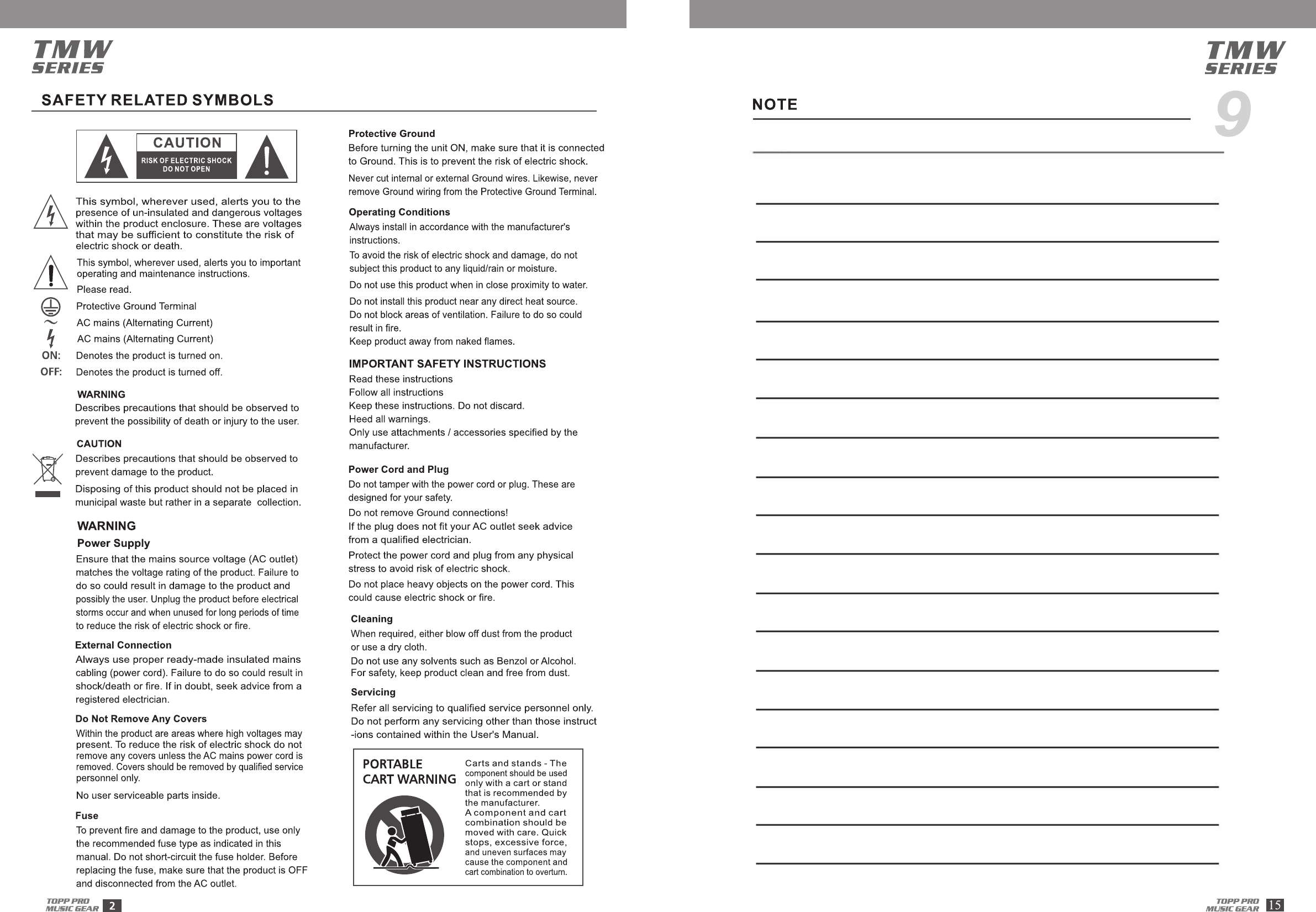
SAFETY RELATED SYMBOLS
CAUTION
RISK OF ELECTRIC SHOCK
DO NOT OPEN
The symbol is used to indicate that some
hazardous live terminals are involved
within this apparatus, even under the
normal operating conditions.
The symbol is used in the service do-
cumentation to indicate that specific
component shall be only replaced by
the component specified in that docu-
mentation for safety reasons.
Protective grounding terminal.
Alternating current /voltage.
ON: Denotes the apparatus turns on.
OFF: Denotes the apparatus turns off, be-
cause of using the single pole switch, be sure
to unplug the AC power to prevent any ele-
ctric shock before you proceed your service.
WARNING: Describes precautions that
should be observed to prevent the danger
of injury or death to the user.
CAUTION: Describes precautions that
should be observed to prevent danger of the
apparatus.
WARNING
Power Supply
Ensure the source voltage matches the
voltage of the power supply before turning
ON the apparatus.
Unplug this apparatus during lightning
storms or when unused for long periods
of time.
External Connection
The external wiring connected to the out-
put hazardous live terminals requires
installation by an instructed person, or
the use of ready-made leads or cords.
Do not Remove any Cover
There are maybe some areas with high
voltages inside, to reduce the risk of electric
shock, do not remove any cover if the power
supply is connected.
The cover should be removed by the qual-
ified personnel only.
No user serviceable parts inside.
Fuse
To prevent a fire, make sure to use fuses
with specified standard (current, voltage,
type). Do not use a different fuse or short
circuit the fuse holder.
Before replacing the fuse, turn OFF the
apparatus and disconnected the power
source.
Protective Grounding
Make sure to connect the protective
grounding to prevent any electric shock
before turning ON the apparatus.
Never cut off the internal or external pro-
tective grounding wire or disconnect the
wiring of protective grounding terminal.
Operating Conditions
This apparatus shall not be exposed to
dripping or splashing and that no objects
filled with liquids, such as vases, shall be
placed on this apparatus.
To reduce the risk of fire or electric shock,
do not expose this apparatus to rain or
moisture.
Do not use this apparatus near water.
Install in accordance with the manufacturer's
Hazardous live terminal .
Disposing of this product should
not be placed in municipal waste
and should be separate collection.

Remark:
1. The values with underlines should be scanned manually by adjusting UP/DOWN key.
2. The following channels can be used simultaneously without any interference.
Group 1-1: 798.125 Group 2-1: 798.325
Group 2-2: 800.725 Group 2-5: 807.925
Group 3-4: 805.725 Group 5-1: 798.925
Group 5-8: 815.725 Group 7-1: 799.325
Group 8-6: 811.525 Group 12-2: 802.725
IMPORTANT SAFETY INSTRUCTIONS
Read these instructions.
Keep these instructions.
Heed all warnings.
Only use attachments/accessories spec-
ified by the manufacturer.
Power Cord and Plug
Do not defeat the safety purpose of the
polarized or grounding type plug.
A polarized plug has two blades with
one wider than the other. A grounding
type plug has two blades and a third
grounding prong. The wide blade or the
third prong are provided for your safety.
If the provided plug does not fit into your
outlet, consult an electrician for replace-
ment of the obsolete outlet.
Protect the power cord from being walk-
ed on or pinched particularly at plugs,
convenience receptacles, and the point
where they exit from the apparatus.
Cleaning
When the apparatus needs a cleaning, you
can blow off dust from the apparatus with
a blower or clean with rag etc.
Don't use solvents such as benzol, alcohol,
or other fluids with very strong volatility and
flammability for cleaning the apparatus body.
Clean only with dry cloth.
Servicing
Refer all servicing to qualified personnel. To
reduce the risk of electric shock, do n ot perform
any servicing other than that contained in the
operating instructions unless you are qualified
to do so .
Servicing is required when the apparatus has
been damaged in any way ,such as power
supply cord or plug is damaged , liquid has
been spilled or objects have fallen into the
apparatus, the apparatus has been exposed
to rain or moisture, does not operate normally,
or has been dropped.
Follow all instructions.
instructions. Do not install near any heat
sources such as radiators, heat registers,
stoves, or other apparatus (including am-
plifiers) that produce heat. Do not block
any ventilation openings.
No naked flame sources, such as lighted
candles, should be placed on the apparatus.
20
F8: 850.000-874.000(850-879)MHz F8: 850.000-874.000(850-879)MHz
1
2
3
4
5
6
7
8
9
10
11
12
Group1 Group2 Group3 Group4 Group5 Group6 Group7 Group8 Group9 Group10 Group11
Group12
850.125 850.325 850.525 850.725 850.925 851.125 851.325 851.525 851.725 851.925 852.125 852.325
852.525 852.725 852.925 853.125 853.325 853.525 853.725 853.925 854.125 854.325 854.525 854.725
854.925 855.125 855.325 855.525 855.725 855.925 856.125 856.325 856.525 856.725 856.925 857.125
857.325 857.525 857.725 857.925 858.125 858.325 858.525 858.725 858.925 859.125 859.325 859.525
859.725 859.925 860.125 860.325 860.525 860.725 860.925 861.125 861.325 861.525 861.725 861.925
862.125 862.325 862.525 862.725 862.925 863.125 863.325 863.525 863.725 863.925 864.125 864.325
864.525 864.725 864.925 865.125 865.325 865.525 865.725 865.925 866.125 866.325 866.525 866.725
866.925 867.125 867.325 867.525 867.725 867.925 868.125 868.325 868.525 868.725 868.925 869.125
869.325 869.525 869.725 869.925 870.125 870.325 870.525 870.725 870.925 871.125 871.325 871.525
871.725 871.925 872.125 872.325 872.525 872.725 872.925 873.125 873.325 873.525 873.725 873.925
874.125 874.325 874.525 874.725 874.925 875.125 875.325 875.525 875.725 875.925 876.125 876.325
876.525 876.725 876.925 877.125 877.325 877.525 877.725 877.925 878.125 878.325 878.525 878.725
This device complies with Part 15 of the FCC Rules.
Operation is subject to the following two conditions:
(1) this device may not cause harmful interference,
and (2) this device must accept any interference received,
including interference that may cause undesired operation.
WARNING: changes or modifications not expressly
approved by the party responsible for compliance could
void the user's authority to operate the equipment.
This equipment has been tested and found to comply with the
limits for a Class B digital device, pursuant to part 15 of the
FCC Rules. These limits are designed to provide reasonable
protection against harmful interference in a residential
installation. This equipment generates, uses and can radiate
radio frequency energy and, if not installed and used in
accordance with the instructions, may cause harmful
interference to radio communications. However, there is no
guarantee that interference will not occur in a particular
installation. If this equipment does cause harmful interference
to radio or television reception, which can be determined by
turning the equipment off and on, the user is encouraged to try
to correct the interference by one or more of the following
measures:
—Reorient or relocate the receiving antenna.
—Increase the separation between the equipment and receiver.
—Connect the equipment into an outlet on a circuit different
from that to which the receiver is connected.
—Consult the dealer or an experienced radio/TV technician for
help.

TABLE OF CONTENTS
1. .. . 1
2. ...... ......... . ........... . ....................5
3. .... . .. .... ......... .............5
4. ... .. ... ... . ... . . ....................9
5.
6.
INTRODUCTION
FEATURES
CONTROL ELEMENTS
OPERATION
TECHNICAL SPECIFICATIONS
ANNEX
. ..................................................................................
.... . ..................... ..... ...............
........ . ..... .......................... ..
... .. .. ... ...................... ..... ........ ..........
............................................................14
...................................................................................................16
19
F6: 740.000-764.000(740-769)MHz F6: 740.000-764.000(740-769)MHz
1
2
3
4
5
6
7
8
9
10
11
12
Group1 Group2 Group3 Group4 Group5 Group6 Group7 Group8 Group9 Group10 Group11
Group12
F7: 798.000-822.000(798-827)MHz F7: 798.000-822.000(798-827)MHz
1
2
3
4
5
6
7
8
9
10
11
12
Group1 Group2 Group3 Group4 Group5 Group6 Group7 Group8 Group9 Group10
Group11
Group12
740.125 740.325 740.525 740.725 740.925 741.125 741.325 741.525 741.725 741.925 742.125 742.325
742.525 742.725 742.925 743.125 743.325 743.525 743.725 743.925 744.125 744.325 744.525 744.725
744.925 745.125 745.325 745.525 745.725 745.925 746.125 746.325 746.525 746.725 746.925 747.125
747.325 747.525 747.725 747.925 748.125 748.325 748.525 748.725 748.925 749.125 749.325 749.525
749.725 749.925 750.125 750.325 750.525 750.725 750.925 751.125 751.325 751.525 751.725 751.925
752.125 752.325 752.525 752.725 752.925 753.125 753.325 753.525 753.725 753.925 754.125 754.325
754.525 754.725 754.925 755.125 755.325 755.525 755.725 755.925 756.125 756.325 756.525 756.725
756.925 757.125 757.325 757.525 757.725 757.925 758.125 758.325 758.525 758.725 758.925 759.125
759.325 759.525 759.725 759.925 760.125 760.325 760.525 760.725 760.925 761.125 761.325 761.525
761.725 761.925 762.125 762.325 762.525 762.725 762.925 763.125 763.325 763.525 763.725 763.925
764.125 764.325 764.525 764.725 764.925 765.125 765.325 765.525 765.725 765.925 766.125 766.325
766.525 766.725 766.925 767.125 767.325 767.525 767.725 767.925 768.125 768.325 768.525 768.725
798.125 798.325 798.525 798.725 798.925 799.125 799.325 799.525 799.725 799.925 800.125 800.325
800.525 800.725 800.925 801.125 801.325 801.525 801.725 801.925 802.125 802.325 802.525 802.725
802.925 803.125 803.325 803.525 803.725 803.925 804.125 804.325 804.525 804.725 804.925 805.125
805.325 805.525 805.725 805.925 806.125 806.325 806.525 806.725 806.925 807.125 807.325 807.525
807.725 807.925 808.125 808.325 808.525 808.725 808.925 809.125 809.325 809.525 809.725 809.925
810.125 810.325 810.525 810.725 810.925 811.125 811.325 811.525 811.725 811.925 812.125 812.325
812.525 812.725 812.925 813.125 813.325 813.525 813.725 813.925 814.125 814.325 814.525 814.725
814.925 815.125 815.325 815.525 815.725 815.925 816.125 816.325 816.525 816.725 816.925 817.125
817.325 817.525 817.725 817.925 818.125 818.325 818.525 818.725 818.925 819.125 819.325 819.525
819.725 819.925 820.125 820.325 820.525 820.725 820.925 821.125 821.325 821.525 821.725 821.925
822.125 822.325 822.525 822.725 822.925 823.125 823.325 823.525 823.725 823.925 824.125 824.325
824.525 824.725 824.925 825.125 825.325 825.525 825.725 825.925 826.125 826.325 826.525 826.725
1
1. INTRODUCTION
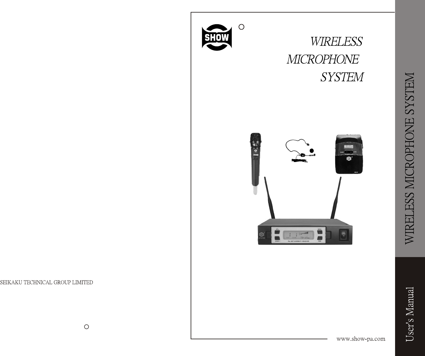
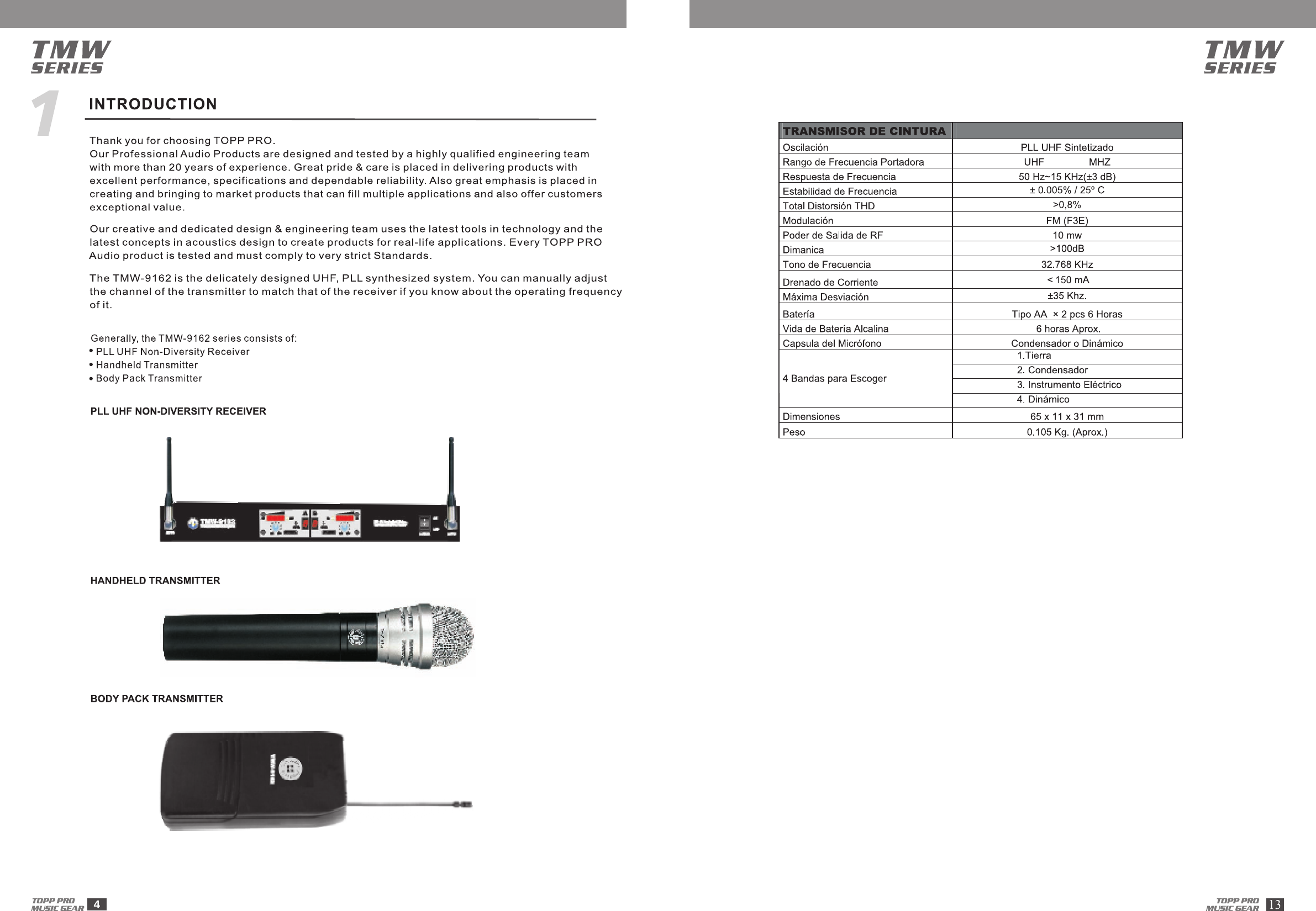
Thanks for purchasing the SHOW wireless microphone system. The UP-81DR/8H/8P
series is the delicately designed UHF, PLL synthesized system, with two antennas built
inside the receiver for smart switching diversity control, the higher level RF signals may
be fed into the system for greater reliability and coverage, therefore, the risks of breakdown
and interference are to be effectively reduced.
By the Auto Scan function provided by the UP-81DR, PLL UHF Diversity Receiver, the
operating frequency of the transmitter may be automatically searched out and locked
by the system. Or, you can manually adjust the channel of the transmitter to match the
receiver in case you know about the operating frequency of it.
Generally, the UP-81DR/8H/8P series consists of
-UP-81DR, PLL UHF Diversity Receiver
-UP-8H, Handheld transmitter
-UP-8P series, Body Pack transmitter
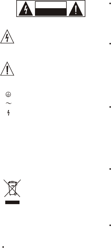
UP-81DR, PLL UHF Diversity Receiver
UP-8H, Handheld transmitter
To well satisfy the different applications , there are 5 models in total are included in
this product range, please make sure that the proper microphone has been selected
for your typical sound reinforcement system before installation.
UP-8H series Handheld Transmitter
Model No. Capsule
UP-81H
Dynamic(S-100)
UP-83H
Dynamic(S-600)
UP-86H
Dynamic(S-500)
UP-87CH
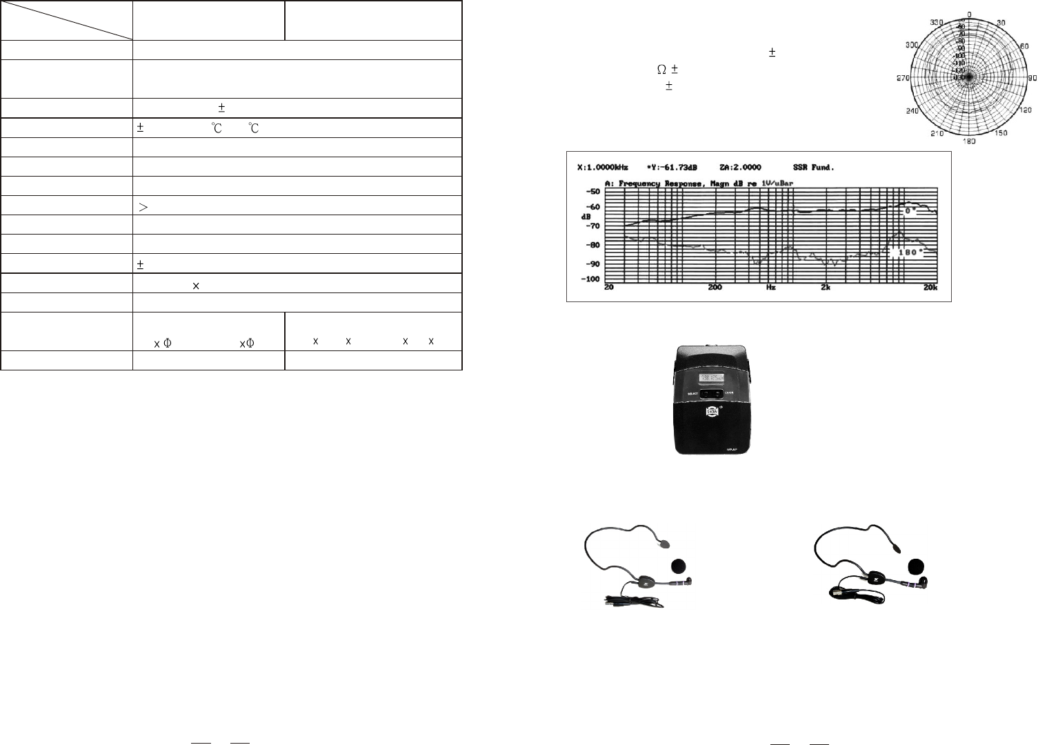
Condenser(C-100)
UP-88CH
Condenser(C-200)
18
F4: 638.000-662.000(638-664)MHz F4: 638.000-662.000(638-664)MHz
F5: 702.000-726.000(702-731)MHz F5: 702.000-726.000(702-731)MHz
1
2
3
4
5
6
7
8
9
10
11
12
Group1 Group2 Group3 Group4 Group5 Group6 Group7 Group8 Group9 Group10 Group11 Group12
702.125 702.325 702.525 702.725 702.925 703.125 703.325 703.525 703.725 703.925 704.125 704.325
704.525 704.725 704.925 705.125 705.325 705.525 705.725 705.925 706.125 706.325 706.525 706.725
706.925 707.125 707.325 707.525 707.725 707.925 708.125 708.325 708.525 708.725 708.925 709.125
709.325 709.525 709.725 709.925 710.125 710.325 710.525 710.725 710.925 711.125 711.325 711.525
711.725 711.925 712.125 712.325 712.525 712.725 712.925 713.125 713.325 713.525 713.725 713.925
714.125 714.325 714.525 714.725 714.925 715.125 715.325 715.525 715.725 715.925 716.125 716.325
716.525 716.725 716.925 717.125 717.325 717.525 717.725 717.925 718.125 718.325 718.525 718.725
718.925 719.125 719.325 719.525 719.725 719.925 720.125 720.325 720.525 720.725 720.925 721.125
721.325 721.525 721.725 721.925 722.125 722.325 722.525 722.725 722.925 723.125 723.325 723.525
723.725 723.925 724.125 724.325 724.525 724.725 724.925 725.125 725.325 725.525 725.725 725.925
726.125 726.325 726.525 726.725 726.925 727.125 727.325 727.525 727.725 727.925 728.125 728.325
728.525 728.725 728.925 729.125 729.325 729.525 729.725 729.925 730.125 730.325 730.525 730.725
1
2
3
4
5
6
7
8
9
10
11
12
Group1 Group2 Group3 Group4 Group5 Group6 Group7 Group8 Group9 Group10
638.125 638.325
638.525
638.725 638.925 639.125 639.325 639.525 639.725 639.925
640.125 640.325
640.525 640.725 640.925 641.125 641.325 641.525 641.725 641.925
642.125 642.325 642.525 642.725
642.925 643.125 643.325 643.525 643.725 643.925
644.125 644.325 644.525 644.725 644.925 645.125
645.325 645.525 645.725 645.925
646.125 646.325 646.525 646.725
646.925
647.125 647.325 647.525
647.725 647.925
648.125 648.325 648.525 648.725 648.925 649.125 649.325 649.525
649.725
649.925
650.125 650.325 650.525 650.725 650.925 651.125 651.325 651.525 651.725 651.925
652.125
652.325
652.525 652.725 652.925 653.125 653.325 653.525 653.725 653.925
654.125 654.325 654.525 654.725
654.925 655.125
655.325
655.525 655.725 655.925
656.125 656.325 656.525 656.725 656.925 657.125
657.325 657.525 657.725 657.925
658.125 658.325 658.525 658.725 658.925 659.125 659.325 659.525
659.725 659.925
660.125 660.325 660.525 660.725 660.925 661.125 661.325 661.525 661.725 661.925
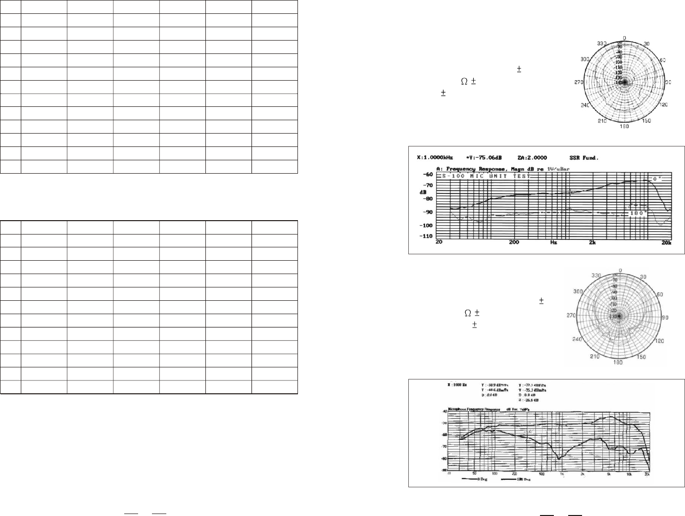
Generally, each model is equipped with the typical type of capsule for specific sound
characteristic, and the RF design keeps the same, please refer to the following specification
of the capsules for more information on the microphone selection to your system.
Type: Dynamic Mic.
Frequency response: 50Hz~15kHz( 3dB)
Impedance: 270 20% at 1kHz
Sensitivity: 0.005%
Direction: Omni-directional
S-100
Type: Dynamic Mic.
Frequency response: 50Hz~16kHz( 3dB)
Impedance: 300 20% at 1kHz
Sensitivity: -71dB 3dB
Direction: Omni-directional
S-600
2
17
F3: 572.000-596.000(572-598)MHz F3: 572.000-596.000(572-598)MHz
F2: 518.000-542.000(518-544)MHz F2: 518.000-542.000(518-544)MHz
1
2
3
4
5
6
7
8
9
10
11
12
Group1 Group2 Group3 Group4 Group5 Group6
1
2
3
4
5
6
7
8
9
10
11
12
Group1 Group2 Group3 Group4 Group5 Group6
518.125 518.325 518.525 518.725 518.925 519.125
519.325 519.525 519.725 519.925 520.125 520.325
520.525 520.725 520.925 521.125 521.325 521.525
521.725 521.925 522.125 522.325 522.525 522.725
522.925 523.125 523.325 523.525 523.725 523.925
524.125 524.325 524.525 524.725 524.925 525.125
525.325 525.525 525.725 525.925 526.125 526.325
526.525 526.725 526.925 527.125 527.325 527.525
527.725 527.925 528.125 528.325 528.525 528.725
528.925 529.125 529.325 529.525 529.725 529.925
530.125 530.325 530.525 530.725 530.925 531.125
531.325 531.525 531.725 531.925 532.125 532.325
572.125 572.325 572.525 572.725 572.925 573.125
573.325 573.525 573.725 573.925 574.125 574.325
574.525 574.725 574.925 575.125 575.325 575.525
575.725 575.925 576.125 576.325 576.525 576.725
576.925 577.125 577.325 577.525 577.725 577.925
578.125 578.325 578.525 578.725 578.925 579.125
579.325 579.525 579.725 579.925 580.125 580.325
580.525 580.725 580.925 581.125 581.325 581.525
581.725 581.925 582.125 582.325 582.525 582.725
582.925 583.125 583.325 583.525 583.725 583.925
584.125 584.325 584.525 584.725 584.925 585.125
585.325 585.525 585.725 585.925 586.125 586.325
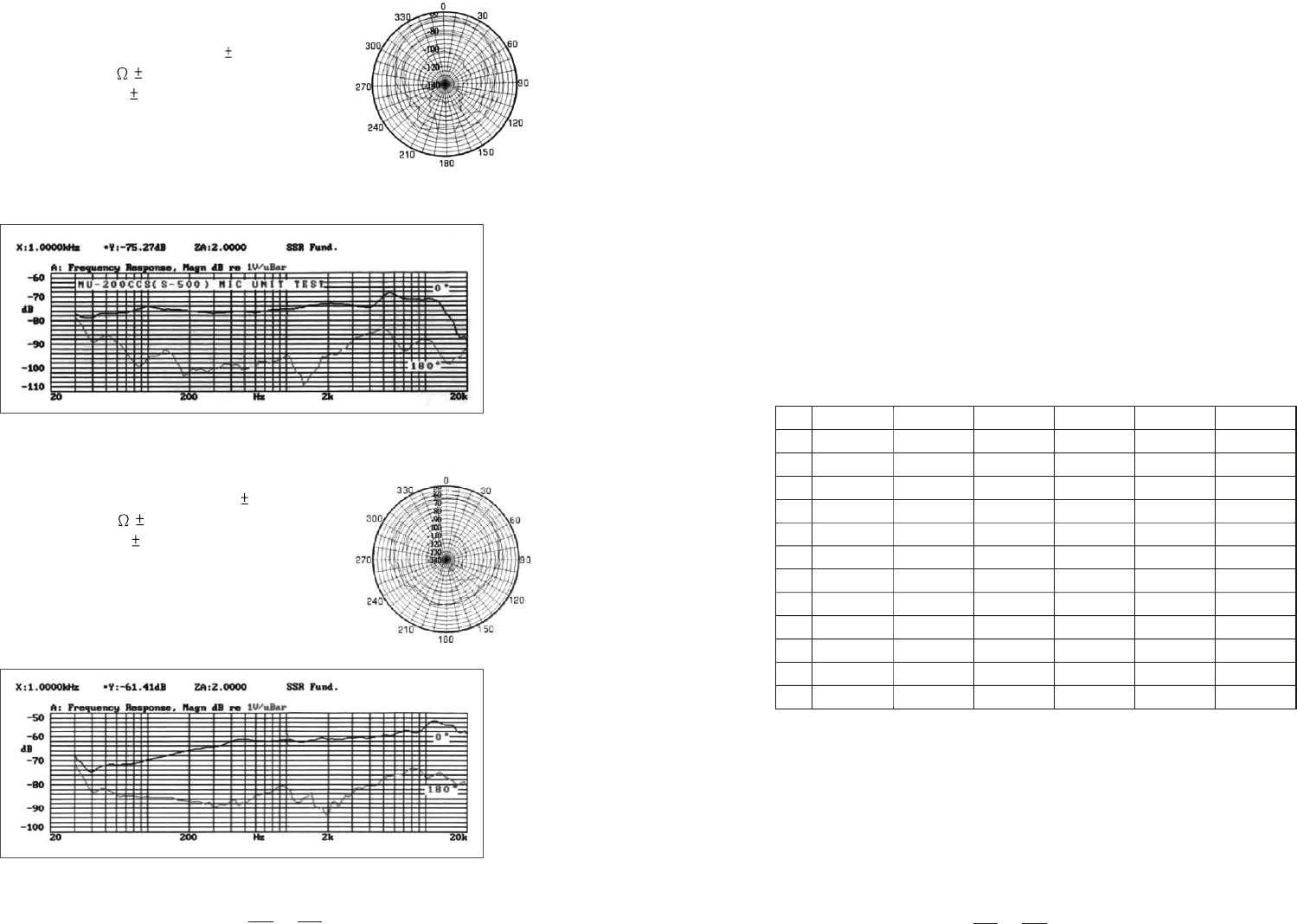
S-500
Type: Dynamic Mic.
Frequency response: 90Hz~12kHz( 3dB)
Impedance: 680 20% at 1kHz
Sensitivity: -52dB 3dB
Direction: Uni-directional
C-100
Type: Condenser Mic.
Frequency response: 50Hz~15kHz( 3dB)
Impedance: 270 20% at 1kHz
Sensitivity: -71dB 3dB
Direction: Omni-directional
316
6. ANNEX
Most countries closely regulate the radio frequencies used in the transmission of
wireless information. These regulations state which devices can use which frequencies,
and help to limit the amount of RF(radio frequency)interference in all wireless
communications.To be flexible enough to operate worldwide, UP-81DR Wireless
receivers are available in a number of models, each with a unique frequency range.
Each frequency range, or band, spans up to 24MHz of the wireless broadcast
spectrum. Available bands are:
6.1 Frequency Band Selection
F1:470.000-494.000(470-496)MHz F2:518.000-542.000(518-544)MHz
F3:572.000-596.000(572-598)MHz F4:638.000-662.000(638-664)MHz
F5:702.000-726.000(702-731)MHz F6:740.000-764.000(740-769)MHz
F7:798.000-822.000(798-827)MHz F8:850.000-874.000(850-879)MHz
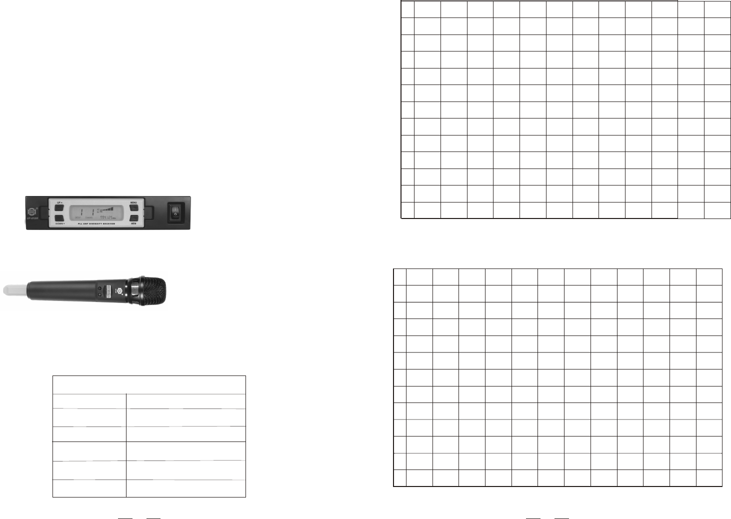
6.2 Frequency Ranges
Group1 Group2 Group3 Group4 Group5 Group6
1
2
3
4
5
6
7
8
9
10
11
12
F1: 470.000-494.000(470-496)MHz F1: 470.000-494.000(470-496)MHz
470.125 470.325 470.525 470.725 470.925 471.125
471.325 471.525 471.725 471.925 472.125 472.325
472.525 472.725 472.925 473.125 473.325 473.525
473.725 473.925 474.125 474.325 474.525 474.725
474.925 475.125 475.325 475.525 475.725 475.925
476.125 476.325 476.525 476.725 476.925 477.125
477.325 477.525 477.725 477.925 478.125 478.325
478.525 478.725 478.925 479.125 479.325 479.525
479.725 479.925 480.125 480.325 480.525 480.725
480.925 481.125 481.325 481.525 481.725 481.925
482.125 482.325 482.525 482.725 482.925 483.125
483.325 483.525 483.725 483.925 484.125 484.325
MODEL
Oscillation mode
Carrier frequency band
Frequency response
Frequency stability
T.H.D.
Modulation mode
RF output power
Dynamic
Tone frequency
Current drain
Max. Deviation
Battery
Optional
Mic. Capsule(optional)
Dimensions
Weight
UP-8H
PLL UHF SYNTHESIZED
UHF 470-900 MHz
Dependent on applicable country regulations
50 Hz-15KHz ( 3dB)
0.005% (-10 ~ 50 )
FM (F3E)
5-50mW(adjustable 3 bands)
100dB
30-33 KHz
100mA
35KHz
"AA" type 2
Nickel hydrogen battery +charger
Condenser or Dynamic Capsule
277 36.5mm (10.9" 1.44")
0.246Kg
UP-8P
1KHz<0.8%
Condenser or Dynamic Capsule
0.009Kg
97mm 68mm 22mm(3.82" 2.68" 0.87")
SPECIFICATION
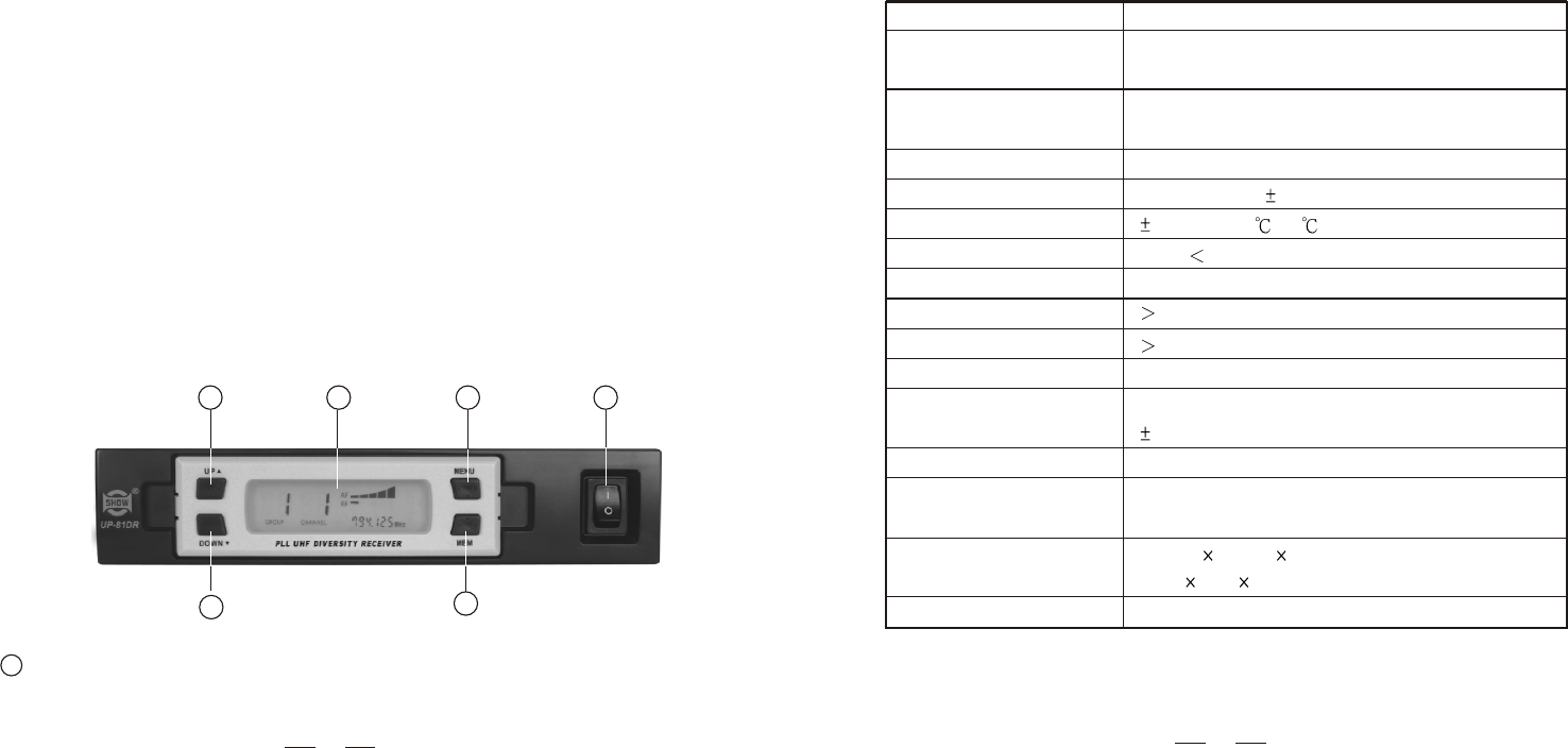
C-200
Type: Condenser Mic.
Frequency response: 100Hz~15kHz( 3dB)
Impedance: 700 30% at 1kHz
Sensitivity: -44dB 3dB
Direction: Uni-directional
UP-8P series, Body Pack transmitter
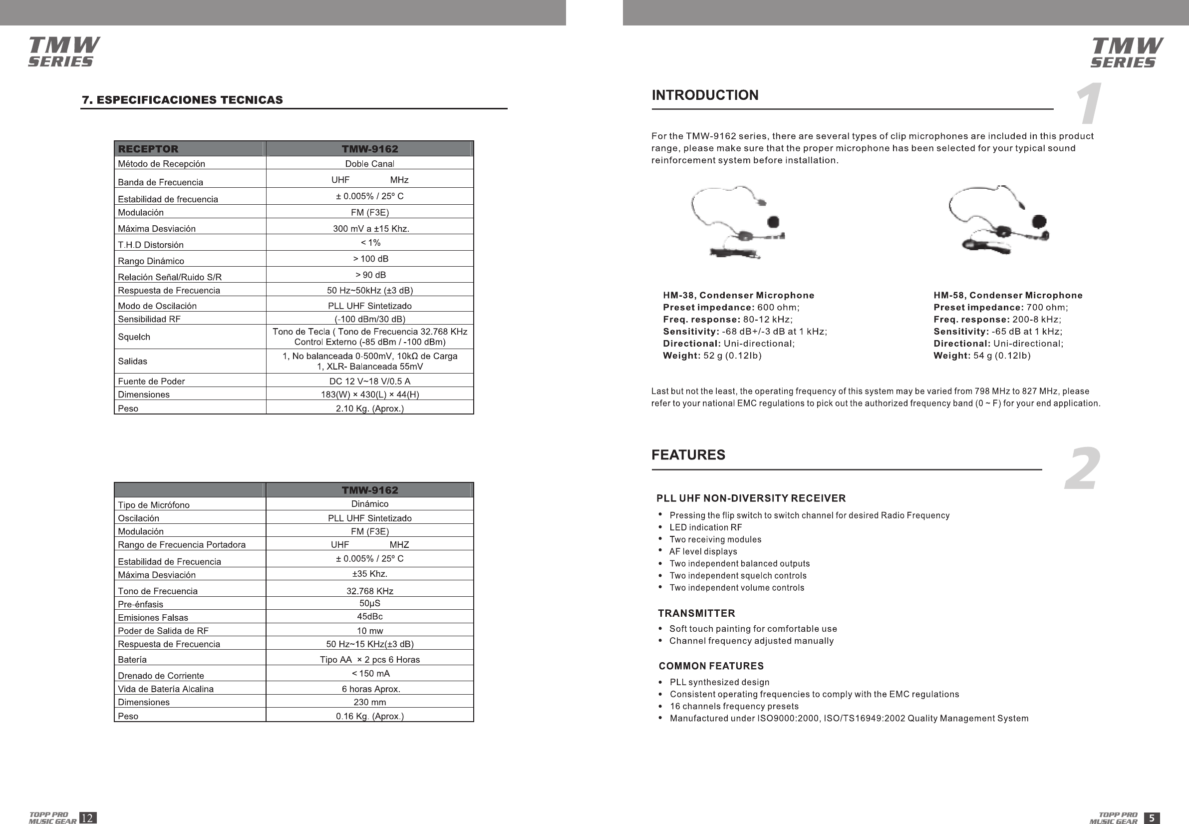
For the UP-8P series, there are several types of clip microphone are included in this product
range, please make sure that the proper microphone has been selected for your typical
sound reinforcement system before installation.
HM-38, Condenser microphone
Preset impedance: 600ohm;
Freq. response: 80-12KHz;
Sensitivity: -68dB+/-3dB at 1KHz;
Directional: Uni-directional;
Weight: 52g (0.12Ib)
HM-58, Condenser microphone
Preset impedance: 700ohm;
Freq. response: 200-8KHz;
Sensitivity: -65dB at 1KHz;
Directional: Uni-directional;
Weight: 54g (0.12Ib)
4
15
470MHz to 900MHz, please refer to your national EMC regulations to pick out the authorized
frequency band (F1 ~ F8, detail please see Annex hereafter) for your end application.
2. FEATURES
-UP-81DR, PLL UHF Diversity Receiver,
-Friendly interface of front panel LCD status display;
-Auto Scan function for easy and convenient operation;
-Switching diversity control to receive the RF signal;
-Three output level versions;
-Squelch control;
-UP-8H/8P transmitters,
-Soft touch painting for comfortable use;
-Rechargeable battery design;
-Three RF output power versions;
-Mute function;
-Lock function to avoid the misaction during the live applications;
-Common features,
-PLL synthesized design;
-Consistent operating frequencies to comply with the EMC regulations;
-Up to 12x12, total 144 channel frequency presets;
-Manufactured under ISO9000:2000, ISO/TS16949:2002 quality management system;
3. CONTROL ELEMENTS
3.1 UP-81DR, PLL UHF Diversity Receiver
Power Switch
It switches on/off UP-81DR main power.
1 1
1 1 2 2 3 3 4 4
5 5
2 2
THE FRONT PANEL
5
Last but not the least, the operating frequency of this wireless system may be varied from
- Adjust from the transmitter,
1) Check the preset frequency (preset group, and preset channel) displayed on the
receiver in Mhz.
2) Switch on the transmitter.
3) Touch the CH/ON key slightly to select the parameters to be edited.
4) Use the Select key to set the proper channel / group.
2) Manually Selecting Frequency
Turn on the receiver . After touch the MENU key, the 'Group' indicated on the LCD
display flashes, and use the UP/DOWN key to select the right group, after it is done, press
'Mem' to store the settings. To edit the preset channel or other parameters, please press
again the MENU key, and so on.
MODEL
Channel
Frequency band
Receiver type
Frequency response
Frequency stability
T.H.D.
Modulation mode
S/N Ratio
Dynamic
RF sensitivity
Audio output
Balance output
Power supply
Dimensions
Weight
UP-81DR
Multi-channels, up to 144 frequency presets for
each frequency bands
UHF 470-900 MHz
Dependent on applicable country regulations
PLL UHF SYNTHESIZED
50 Hz-15KHz ( 3dB)
0.005% (-10 -50 )
1KHZ 0.8%
FM (F3E)
90dB
100dB
-100 dBm/30dB SINAD
Unbalanced 6.3mm phone jack 750mV ;
35KHz deviation
1V , 35KHz deviation
DC 12-18V/ 500mA
5. TECHNICAL SPECIFICATIONS
14
210(W) 165 (D) 50(H)mm
(8.3" 6.5" 1.9)
1.046Kg
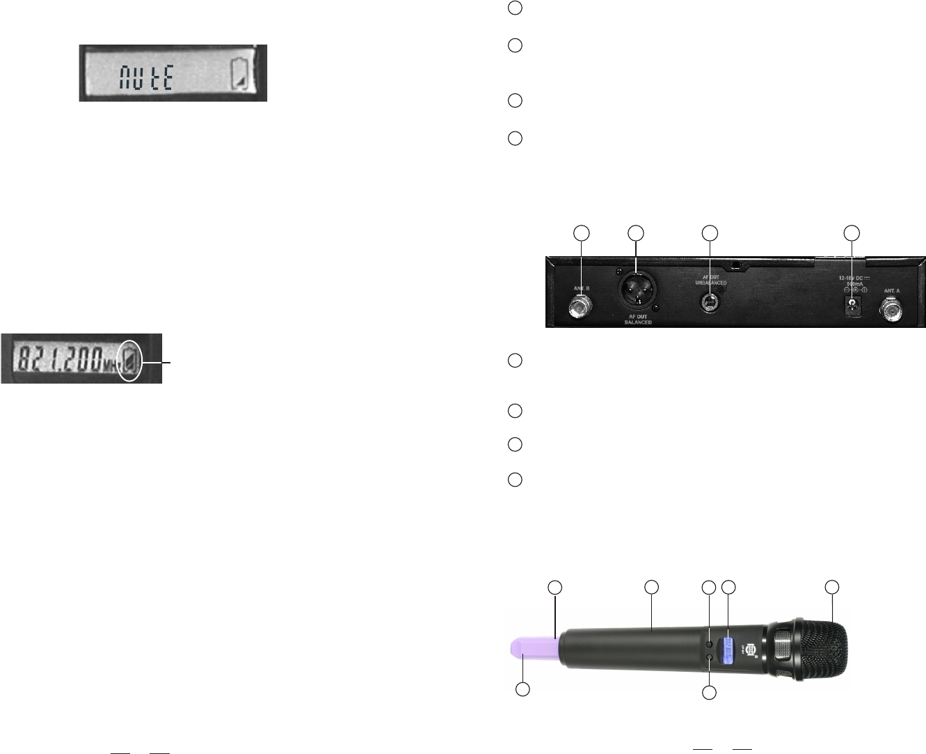
Menu key
Via this key, you can choose the right function you want.
4 4
UP/DOWN key
In the menu mode, you can choose the right value via these two keys.
Display
The LCD shows RF/AF signal, remaining battery life of the transmitter, group
value, channel value and the selected frequency.
2 2
3 3
It is equipped with two functions, memo function, and auto scan function.
MEM key
5 5
THE REAR PANEL
Antenna Input Socket
Allow you to connect plug-in antennas, remote antennas, or even a complex
antenna network.
XLR Audio Output
This is a professional balanced XLR output connector.
Audio Output Jack
This is a professional unbalanced output jack.
It is used to connect an attached adapter.
1 1 2 2 3 3 4 4
1 1
2 2
3 3
DC Input
4 4
3.2 UP-8H, Handheld Transmitter
6
3 3
7 7
6 6 1 1
2 2
4 4
5 5
Fig 12
4.2.3 Battery Replacing And Charging
Please be advised to use only UM3 size AA 1.5V, one pair batteries for power supply.
If the rechargeable batteries are used,
- Please keep the batteries inside, and use the charger (optional accessory, provided
by the manufacturer) to recover the batteries.
- During the charging process, the "Remaining battery life display" flashes.
- Normally, the battery should be recharged within 6-hour.
Note: when the transmitter is muted, the microphone couldn't send out any AF signal, that
means, no sound has been sent out from the microphone.
Remaining battery life display
Fig 13
Caution: Danger of explosion if battery is incorrectly replaced. Replace only with the
same or equivalent type.
4.3 Operating frequency matches between the receiver and the transmitter
To make the operating frequency matched between the transmitter and the receiver,
there are two options,
- Controlled from the receiver,
1) Auto Scan
Turn on the receiver, the MEM key press for a few seconds to enter into the auto
scan mode. You can see"SCAN" flashes on the top left of the LCD, it means the
auto scan function has been activated. under the auto scan mode, the scan function
automatically searches the receiver's entire frequency band from start to stop.
During the search, these presets of GROUP, CHANNEL and frequency keep
flashing as they are scanned. As soon as the stop frequency is reached, the scan will
be stopped automatically, the value of frequency is keeping flashing channel preset,
press the MEM key, you can save the information.
Remark: some frequencies should be scanned manually by adjusting UP/DOWN Key,
please refer to use's manual of UP-81DR for details!
13
Use this key to edit the parameters in operation mode. Keep pressing this key for a
few seconds, the unit will enter into the mute mode, repeat for unmute.
SELECT Key
4 4
such as the preset channel, preset group, PL (RF power level), and Lock/unlock; In
this mode, if there is no further operation in the next few seconds, it will return to the
main menu, and the LCD displays again the current preset frequency in MHz, as well
as the battery status.
The unit may be powered from a dry or rechargeable battery.
Please make sure that it is the rechargeable batteries inside before plug the
recharger with the mini charge jack.
Connect the optional recharger(see fig) with this mini jack for battery recharging.
The antenna is integrated into the transmitter body; to get effective RF transmission,
never cover the antenna with hand, etc.
Battery Compartment
5 5
Charge Jack
6 6
Antenna
7 7
3 3
1 1
2 2
5 5
4 4
8 8
6 6
7 7
3.3 UP-8P series, Body Pack Transmitter
7
Extremely rugged spring steel mesh grill to protect the capsule underneath in tough
stage or live performance.
Massive Front Grill
1 1
Generally, the LCD displays the current operation status.
Keep pressing this key for a few seconds, the unit will be powered on or off. After it
is switched on, touch this key slightly to select the parameter which you want to edit,
LCD Display
2 2
CH/ON Key
3 3
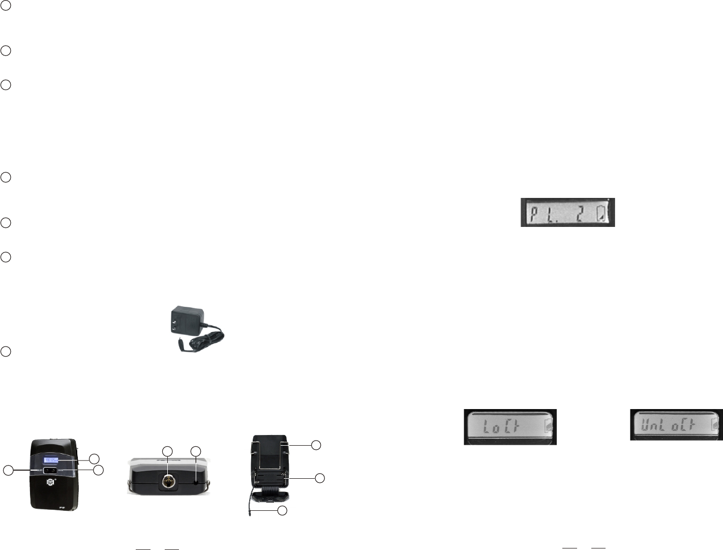
Please follow the below procedure to select the proper RF output power,
- Touch the CH/ON key slightly to select the edited parameter of PL (refer to Fig 9),
then use the SELECT key to specify the proper RF output Power version;
- Several seconds later after that, the system stores the settings automatically, and
LCD display comes back to the main menu which shows the current operation status.
- RF Output Power Select
Three different RF output power versions are available of UP-8H,
- PL 0, the output power is 5dBm;
- PL 1, the output power is 10dBm;
- PL 2, the output power is 15dBm;
But, It's a different from UP-8P,
- PL 0, the output power is 3dBm;
- PL 1, the output power is 5dBm;
- PL 2, the output power is 12dBm;
Fig 9
Since the CH/ON and SELECT keys may be easily activated by simple touch, to avoid any
mis-action during the live application, the Lock/Unlock is provided by this system for touch-proof
under the Locked situation.
In case the system is locked, you can still use the CH/ON key to select the edited parameters,
but, except for the Lock/Unlock, others can't be edited.
- LOCK Function
To enter into the Lock mode, please follow the below procedure,
- Touch the CH/ON key slightly to select the edited parameter of Lock/Unlock (refer to Fig 10
& 11), then use the SELECT key to specify Lock or Unlock;
- Several seconds later after that, the system stores the settings automatically, and LCD
display comes back to the main menu which shows the current operation status.
Fig 10: LOCK
Fig 11: UNLOCK
4.2.2 Mute Mode Operation
Keep pressing the SELECT key for a few seconds, the unit will enter into the mute mode
(see the fig 12), repeat for unmute.
12
CH/ON Key
Keep pressing this key for a few seconds, the unit will be powered on or off. After it
is switched on, touch this key slightly to select the parameter which you want to edit,
such as the preset channel, preset group, PL(RF power level) and Lock/unlock. In
this mode, if there is no further operation in the next few seconds, it will return to the
main menu, and the LCD displays again the current preset frequency in MHz, as well
as the battery status.
SELECT Key
Use this key to edit the parameters in operation mode. Keep pressing this key for a
few seconds, the unit will enter into the mute mode, repeat for unmute.
2 2
3 3
4 4
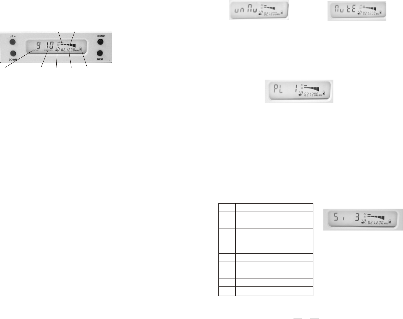
Mini 4P connector
This connector is used to connect the unit with the clip microphones, for example, HM-38
or HM-58 condenser microphones.
1 1
LCD Display
Generally, the LCD displays the current operation status.
3 3
1 1 4 4
2 2
Pin 2, GND
Pin 4, for Dynamic or condenser microphone
Antenna
It is the flexible antenna. To get effective transmission, never cover the antenna with
hand, clothes, etc during the operation, and always position the transmitter nearby the
receiver.
8 8
Charge Jack
With the rechargeable batteries put inside, use the charger (optional accessory,
provided by the manufacturer) to recharge the batteries. For detail operation, please
refer to chapter 4.2.3, Battery replacing and charging.
5 5
Battery Compartment
This unit may be powered from one pair dry or rechargeable batteries, UM3 size AA 1.5V.
6 6
Belt clip
It is the detachable belt clip for easy carry during the live applications.
7 7
8
4.2 For the UP-8H/8P series transmitters
Press and hold the CH/ON key for a few seconds, then the transmitter is powered
on. Now, the LCD displays the current operation status:
Fig 6
Preset frequency Remaining battery life
4.2.1 Edit The Parameter
Fig 7 Fig 8
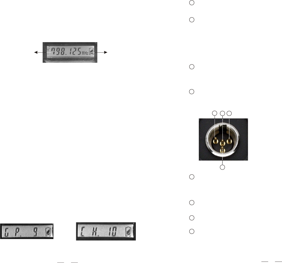
- Frequency select
It is the multi-channels PLL synthesized system. In practice, to effectively avoid the
interference from any lighting equipment, computers, fax machines, etc nearby, it is
usually advised to switch to another frequency to get best performance.
After the transmitter is switched on, touch the CH/ON key slightly to select the
parameter which you want to edit, such as the preset channel, preset group, PL
(RF power level), and Lock/unlock.
The frequency range of this system is UHF, 470MHz ~ 900MHz, and it is divided into 8
frequency bands (F1 ~ F8) according to the country's EMC regulations; For each frequency
band, to select the proper frequency preset, please first pickup the right Group, then specify
the Channel; For details please refer to the Annex;
For example, in F7 frequency band, if you want to select the frequency preset of 811.125MHz
(Group 6, Channel 6), please follow the below procedure,
- Touch the CH/ON key slightly again to select the edited parameter of Group (refer to Fig 7),
then use the SELECT key to specify the proper Group.
- Several seconds later after that, the system stores the settings automatically, and LCD
display comes back to the main menu which shows the current operation status.
- Turn on the unit first.
- Touch the CH/ON key slightly to select the edited parameter of Channel (refer to Fig 8), then
use the SELECT key to specify the proper channel.
11
Pin 3, Phantom power supply for Condenser microphone
Pin 1, for Guitar, bass and keyboards
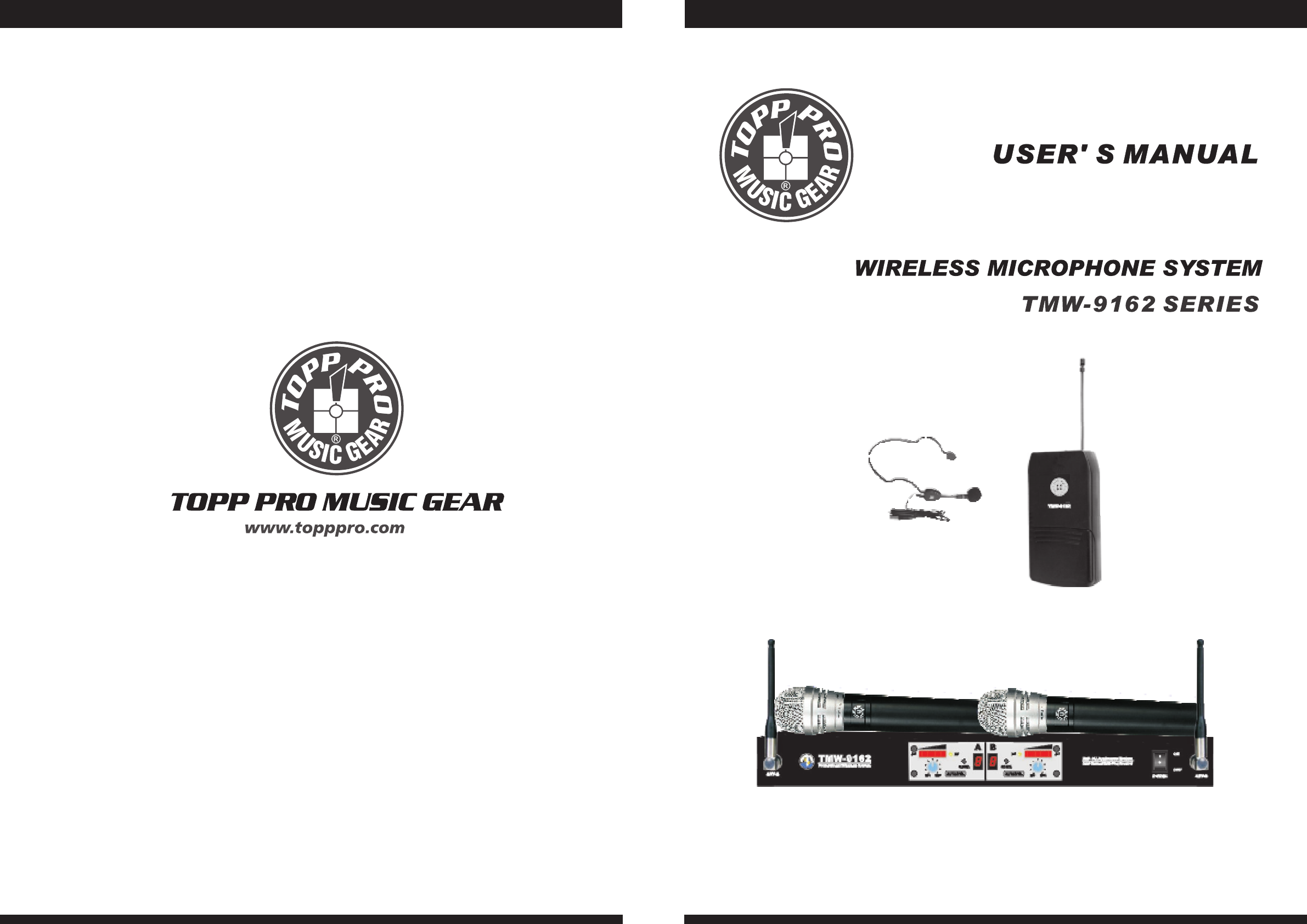
4. OPERATION
A B CD E
FG
Fig 1
A: Frequency group
B: Subchannel
C: Mute(if the mute function is engaged, the mute label is shown, if not , the label
disappears)
D: The selected frequency
E: Remaining battery life of transmitter
4.1 For the UP-81DR, PLL UHF Diversity Receiver
- Auto Scan
- Manual Selecting Frequency
Press the MENU button, "GROUP" is flashing, you can choose the right frequency
group you need via the UP/ DOWN button, when the frequency group is set, please
press MEN button to store the information. Press the MENU button two times,
"CHANNEL" is flashing, you can choose the right subchannel you need via the
UP/DOWN button, when the subchannel you need is set, please press the MEN
- Mute Function
In mute mode, use UP/DOWN key to on/off the mute function.(fig 2: mute function off,
fig 3: mute function on), press the MEM button to keep the information.
Note: when the transmitter is muted, no audio signal will be send out from the receiver.
When the receiver is powered on, press and hold the MEN key for one second,
the receiver is in auto scanning. The scan function automatically searches the
receiver's entire frequency band from start to stop. During the search, the audio
output is muted and the display indicates the frequencies in MHz as they are
scanned. As soon as the correct frequency is reached, the scan will be stopped
automatically, the value of frequency will be flashing, press the MEM key, you
Remark: some frequencies should be scanned manually by adjusting UP/DOWN
key, please refer to Annex for details!
G: RF bar graph indicating the field strength of the received signal.
F: Audio bar graph indicating the receiver audio level
9
can save the information.
button to save it.
Fig 3 mute function on
Fig 2 mute function off
- Output Level Adjusting
In output level adjusting mode(see fig 4), use the SELECT button to adjust the output
level. The output level has 3 choices, 0 indicates the output level is 500mV, 1 indicates
the output level is 300mV, 2 indicates the output level is 150mV.
Note: the function is only applied to the level of Balanced output.
Fig 4
below a defined threshold. The squelch control on the receiver sets this threshold.
will not only cut out noise but mute quiet audio signals as well because the squelch
responds to the detected voltage and cannot distinguish between wanted signal and
noise. Besides that, a too high squelch threshold also decreases the usable range.
In the squelch control mode(fig 5), use the UP/DOWN key to select squelch threshold.
The job of a squelch circuit is to reduce audible noise. It eliminates noise during
pauses in the audio signal by muting the receiver every time the audio level drops
Use the squelch control with care! If the squelch threshold is too high, the squelch
In order to achieve easy operation, the squelch threshold is divided into10 levels, please
- Squelch Control
refer to table.
Fig 5
No. squelch threshold
1
2
3
4
5
6
7
8
9
10
Table
95.0dB
91.7dB
88.3dB
85.0dB
81.7dB
78.3dB
75.0dB
71.7dB
68.3dB
65.0dB
10
NF03738-1.0
This device complies with Part 15 of the FCC Rules.
Operation is subject to the following two conditions:
(1) this device may not cause harmful interference,
and (2) this device must accept any interference received,
including interference that may cause undesired operation.
WARNING: changes or modifications not expressly
approved by the party responsible for compliance could
void the user's authority to operate the equipment.
638~827
This equipment has been tested and found to comply with the limits for a Class B
digital device, pursuant to part 15 of the FCC Rules. These limits are designed to
provide reasonable protection against harmful interference in a residential installation.
This equipment generates, uses and can radiate radio frequency energy and, if not
installed and used in accordance with the instructions, may cause harmful
interference to radio communications. However, there is no guarantee that
interference will not occur in a particular installation. If this equipment does cause
harmful interference to radio or television reception, which can be determined by
turning the equipment off and on, the user is encouraged to try to correct the
interference by one or more of the following measures:
—Reorient or relocate the receiving antenna.
—Increase the separation between the equipment and receiver.
—Connect the equipment into an outlet on a circuit different from that to which the
receiver is connected.
—Consult the dealer or an experienced radio/TV technician for help.
638~827
638~827