Sena Technologies IW07 Bluetooth Serial Adapter User Manual Contents
Sena Technologies,Inc. Bluetooth Serial Adapter Contents
UserManual.wiki
>
Sena Technologies
>
IW07 User Manual
User Manual
Navigation menu
Upload a User Manual
Namespaces
Wiki Guide
HTML
PDF
Info
Views
User Manual
Discussion / Help
Navigation
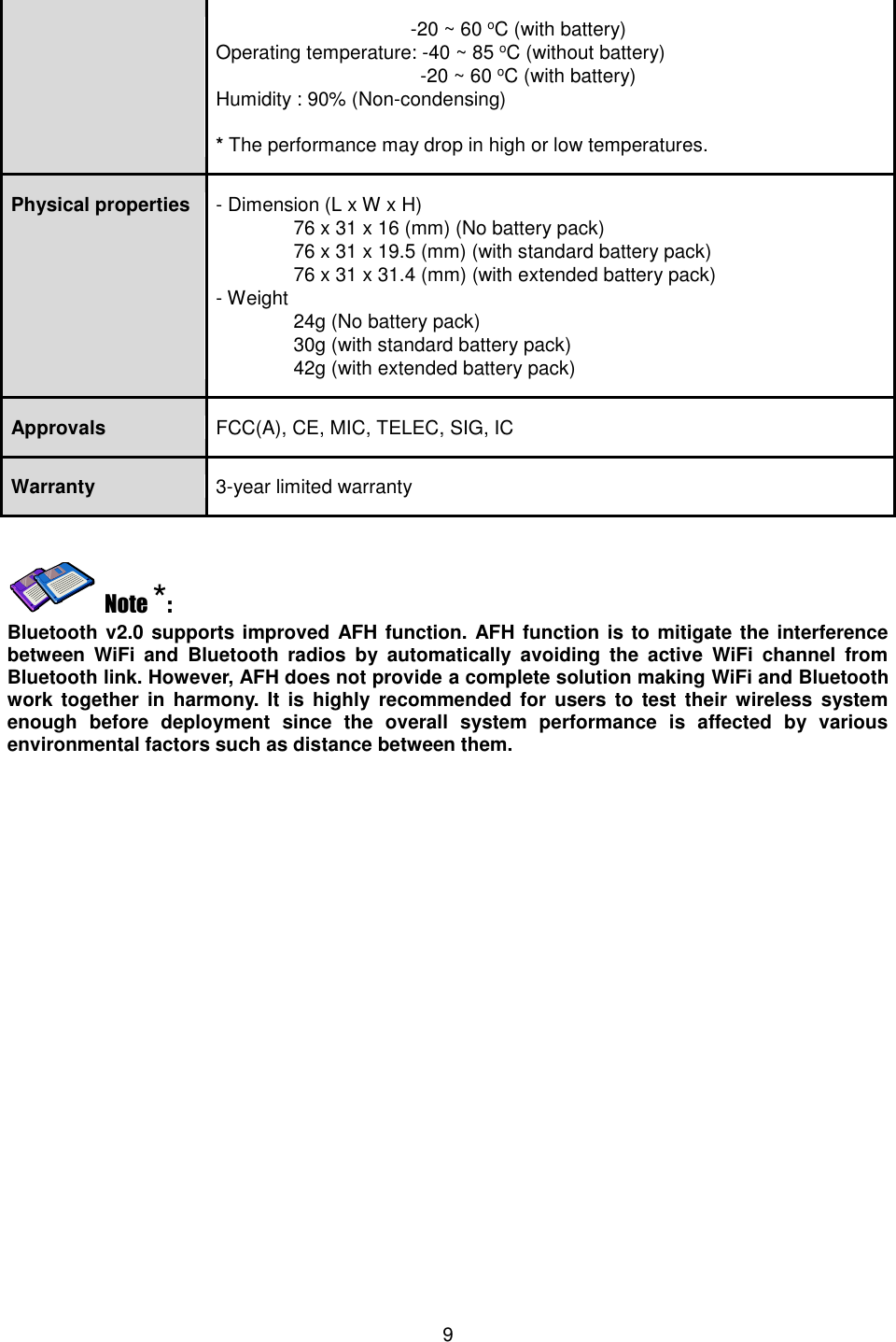
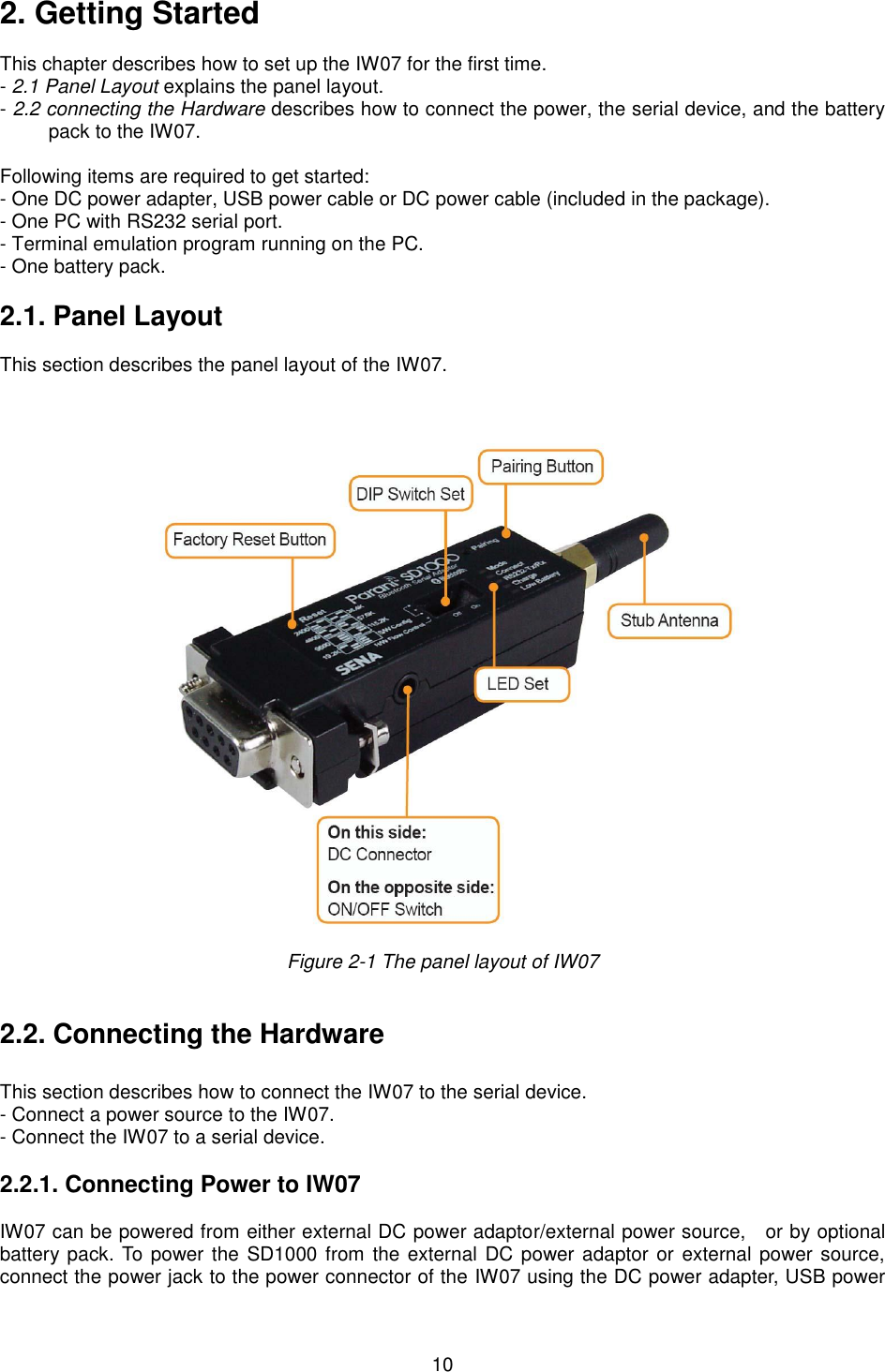
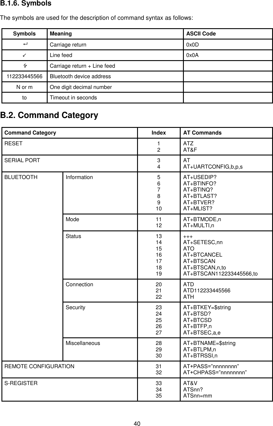
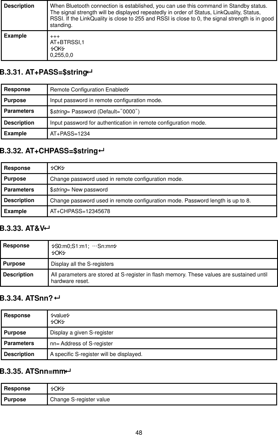
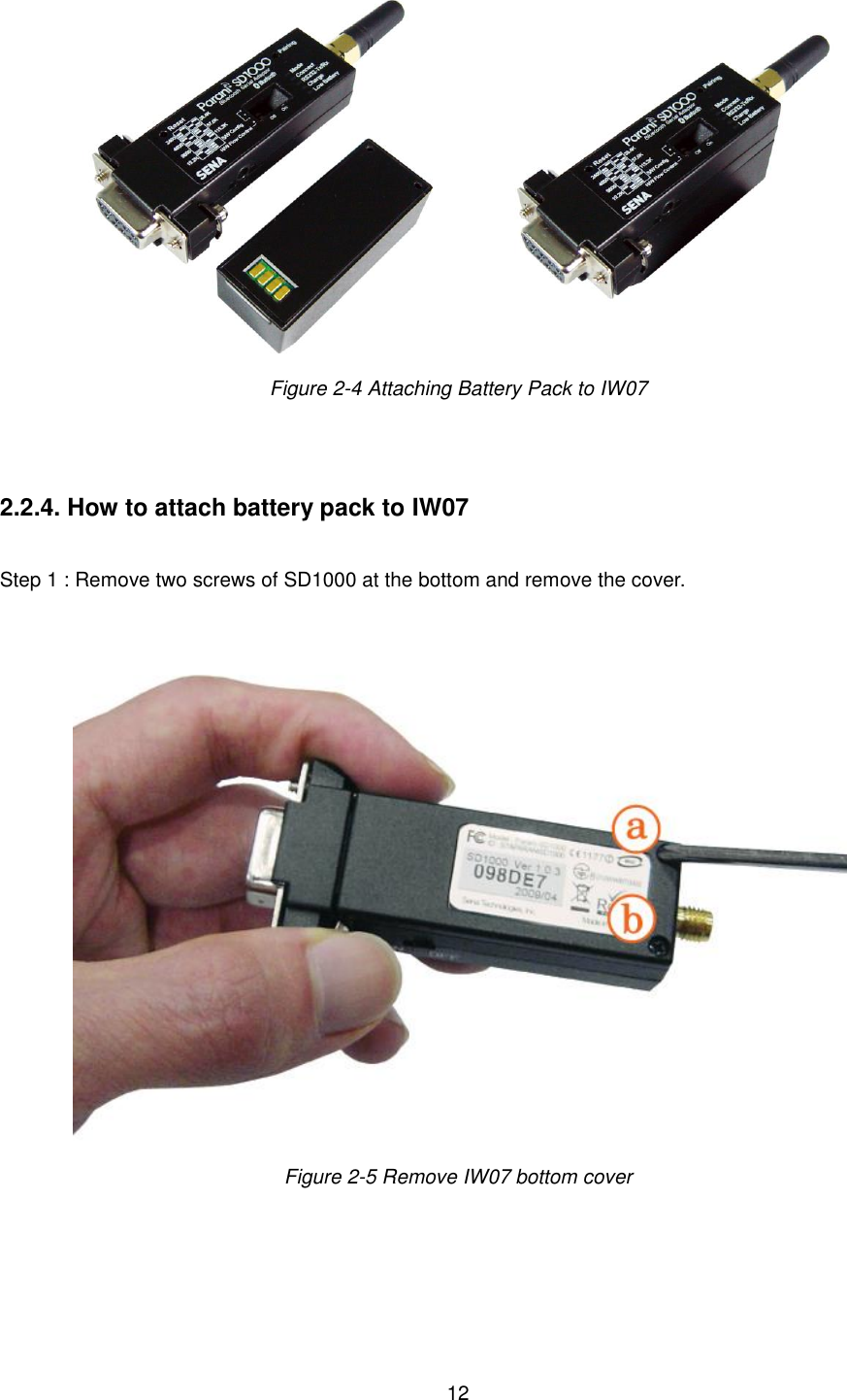
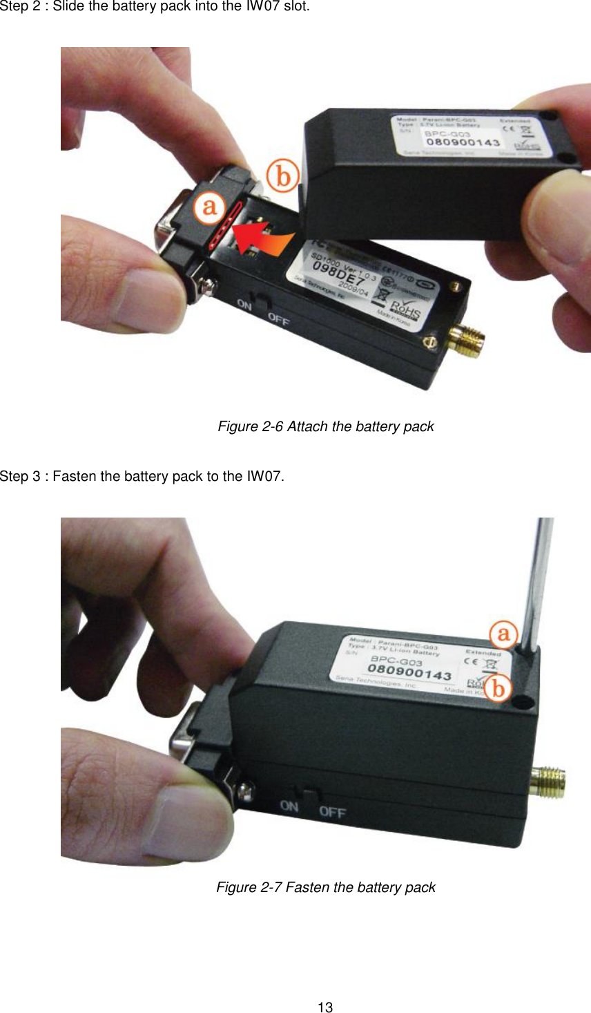
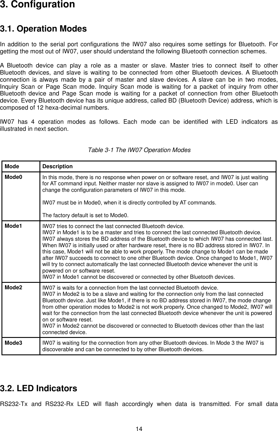
![11 cable or DC power cable that is included in the package. If power is properly supplied, the [Mode] lamp will display a green color. Figure 2-2 Connecting Power to IW07 2.2.2. Connecting Device to IW07 Connect the serial device to the IW07 as shown below. Figure 2-3 Connecting a Serial Device to IW07 2.2.3. Attaching Battery Pack to IW07 The IW07 also supports optional standard battery pack (240mAh) and extended battery pack (900mAh). Attach the battery pack to the IW07 as shown below to power the SD1000 using the battery pack. To recharge the battery pack, connect the external DC power adaptor as described in Section 2.2.1.](https://usermanual.wiki/Sena-Technologies/IW07/User-Guide-3233391-Page-11.png)
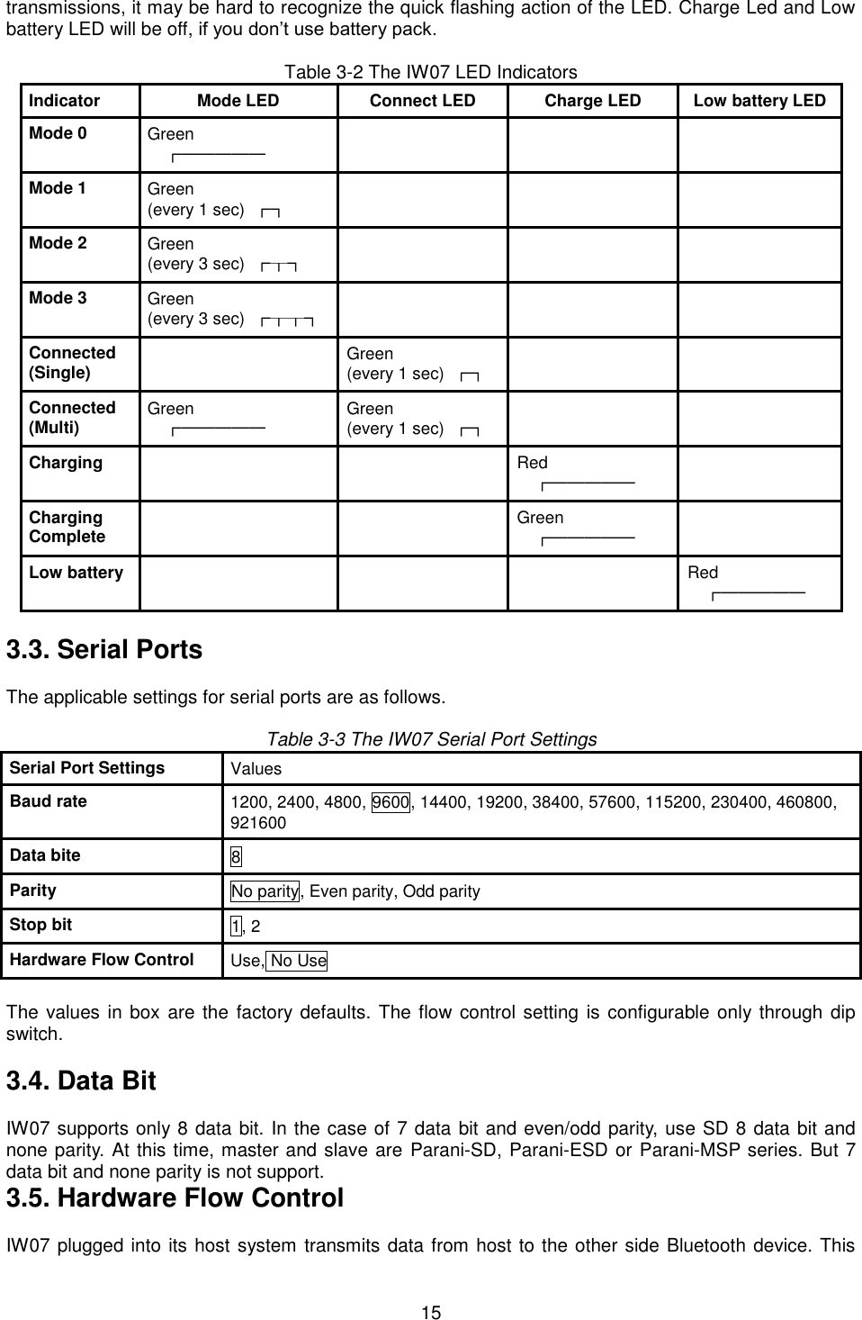
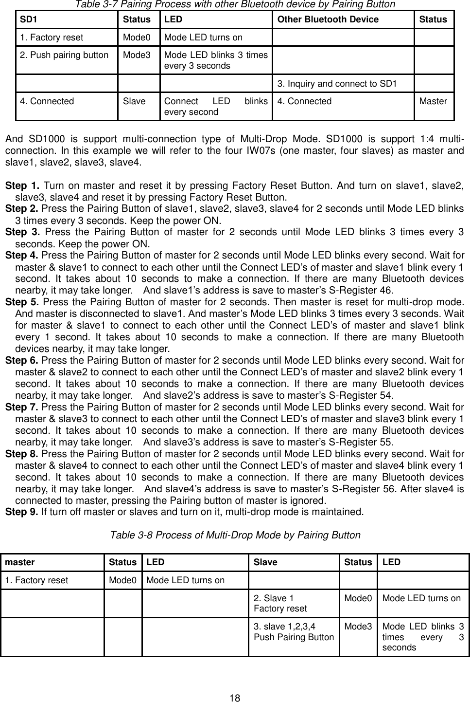
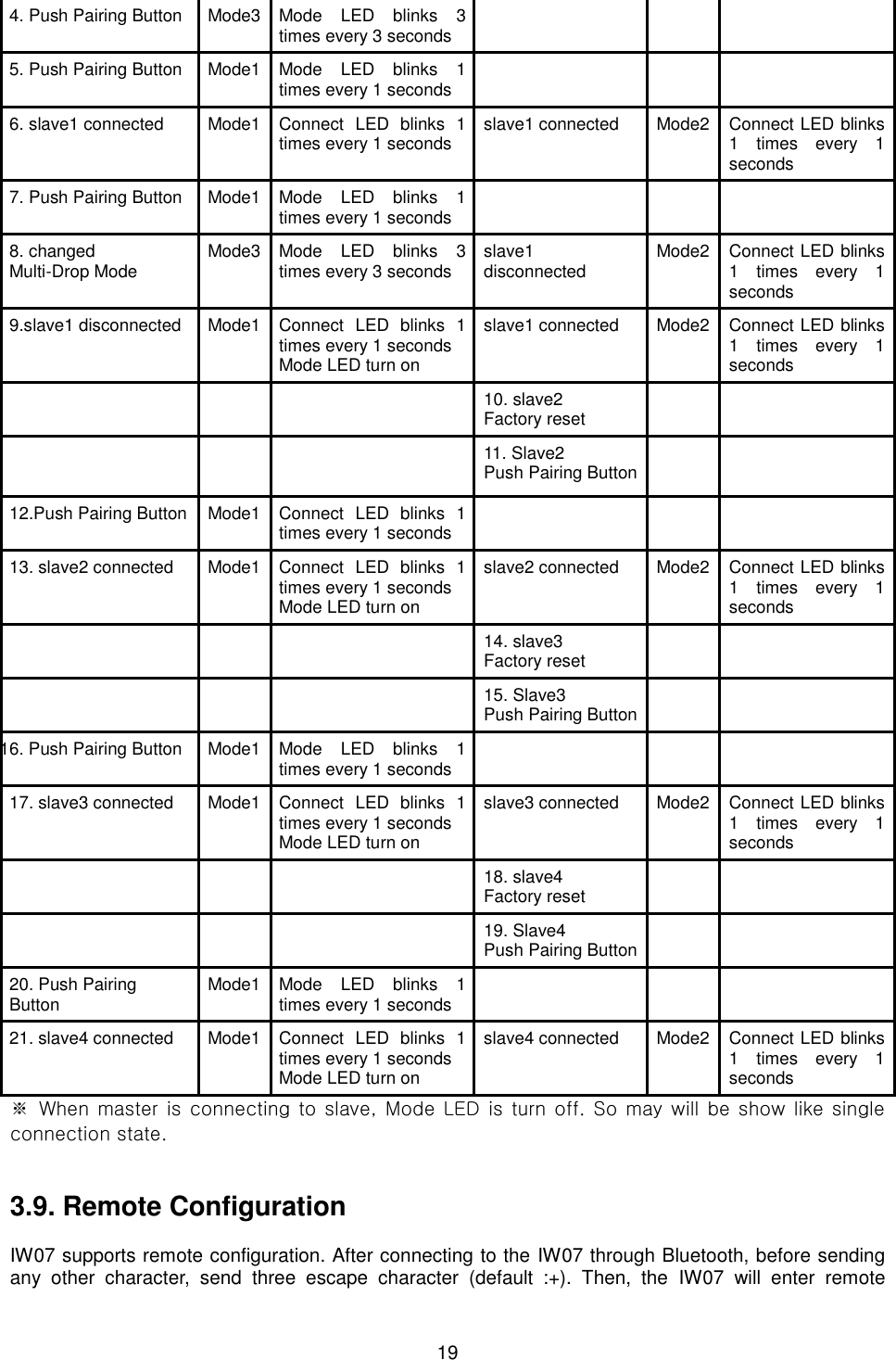
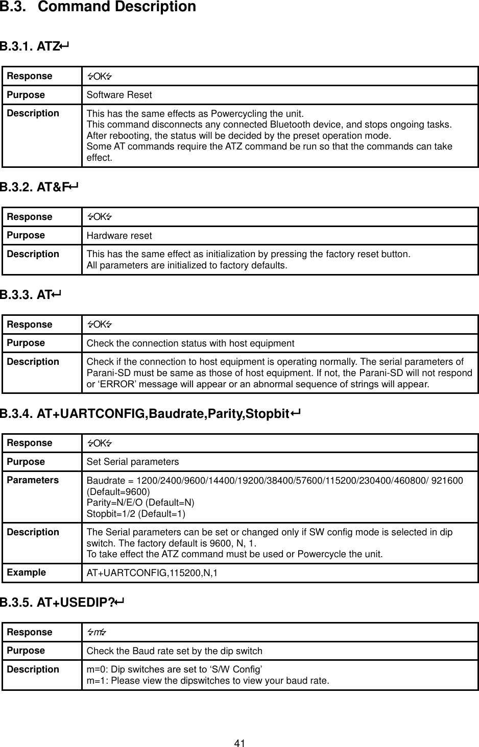
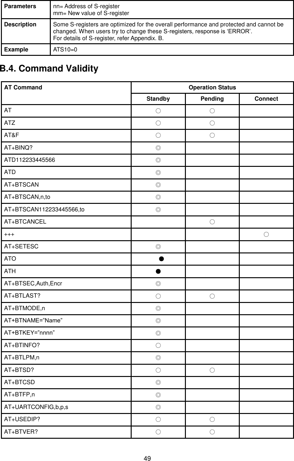
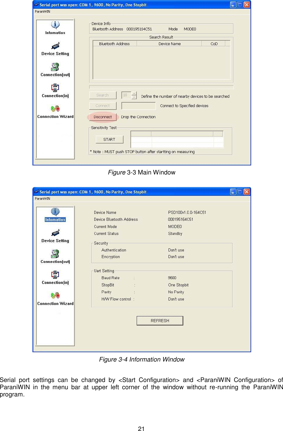
![20 configuration mode and print “Please Enter Password”. You have to enter the password with “AT+PASS” command within 2 minutes. After the password authentication, you are able to enter any at command except “ATH”, “ATO”, “ATD”, “AT+BTSCAN”, “AT+BTINQ?” and “AT+BTCANCEL”. The default password is “0000” and it is configurable with “AT+CHPASS” command. Example of remote configuration mode. 3.10. Software and Utility This configuration software and utility for firmware update is included with the product, which also can be downloaded from http://www.senaindustrial.com Table 3-9 Configuration Software Software Purpose Operating System ParaniWIN Configuration MS Windows 98SE or Higher ParaniMultiWizard Multi Configuration MS Windows 98SE or Higher ParaniUpdater Firmware Update MS Windows 98SE or Higher 3.11. ParaniWIN ParaniWIN is a program that runs on Microsoft Windows for the configuration of IW07. Install ParaniWIN on your computer. Plug a IW07 into the serial port of the computer and turn on the power. Run ParaniWIN. Figure 3-2 Serial Port Setting Set each option properly and click [Confirm]. If the settings of the IW07 are different from the ParaniWin, an error message will pop up. If the IW07 is in the status of connection, warning message will pop up. Then the current connection can be cancelled by [Disconnect] button on the main window. CONNECT 000195000001 +++ Please Enter Password AT+PASS=0000 Remote Configuration Enabled AT+BTINFO? 000195000001,SD1000v2.0.3-095515,MODE0,CONNECT,0,0,HWFC](https://usermanual.wiki/Sena-Technologies/IW07/User-Guide-3233391-Page-20.png)
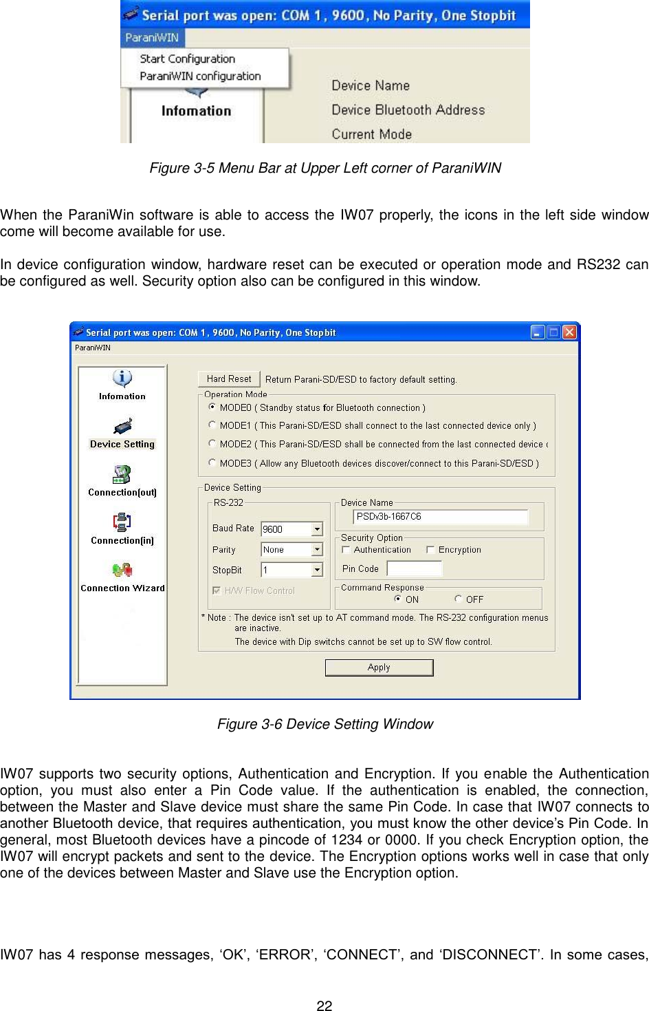
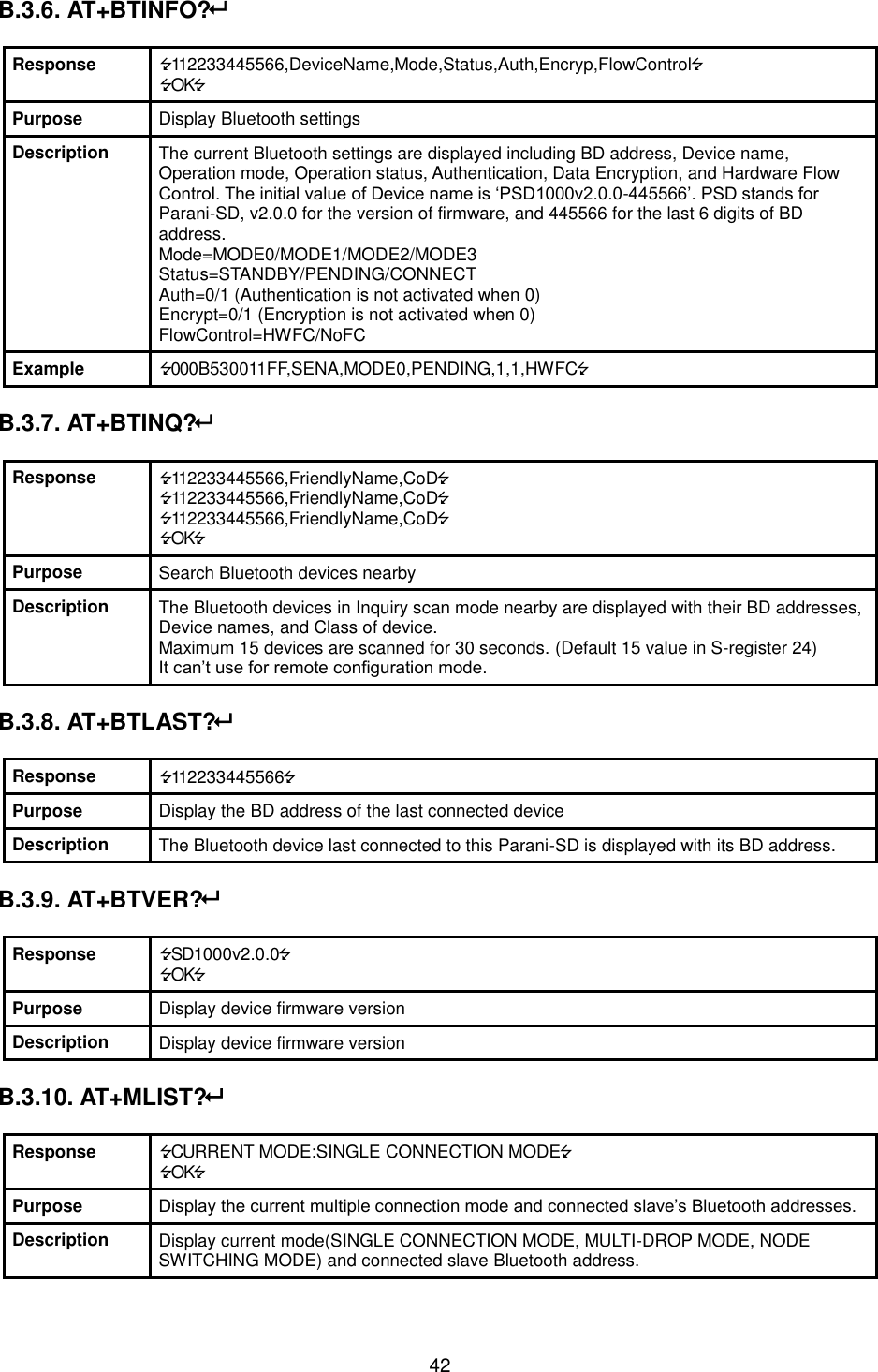
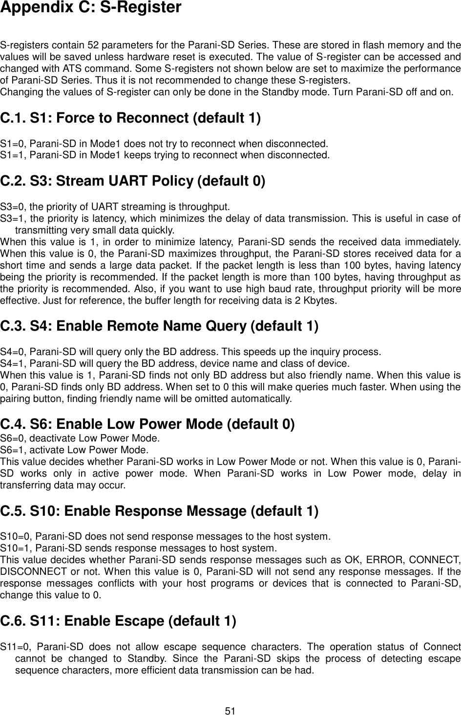
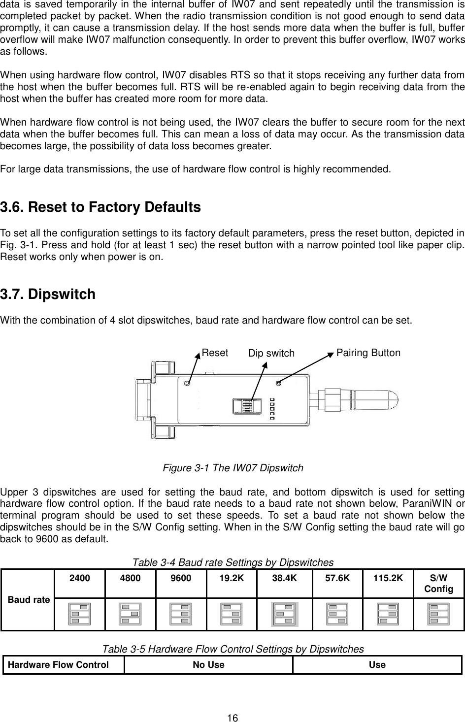
![23 these responses can affect the host system unexpectedly. To prevent this, user can set the Command response to ON or OFF. For IW07, hardware flow control can be configured only by dip switch. And parity, stop bit can be configured only SW config mode. Thus H/W Flow Control option will not work in this case. When the dipswitch value isn’t ATcommand mode, the Baud Rate menu will be disabled. Click [Apply] button to apply any changes made to the IW07. Connection(out) icon will show the following window to search and connect other Bluetooth devices. Figure 3-7 Connection (out) Window Click [Search] button to search nearby Bluetooth devices. Once several Bluetooth devices has been found, select one of the devices and click the [Connect] button. The selected Bluetooth device must be discoverable and connectable. Click [Disconnect] button to cancel the connection. After the connection has been established, you will be able to test signal strength by pushing the START button.](https://usermanual.wiki/Sena-Technologies/IW07/User-Guide-3233391-Page-23.png)
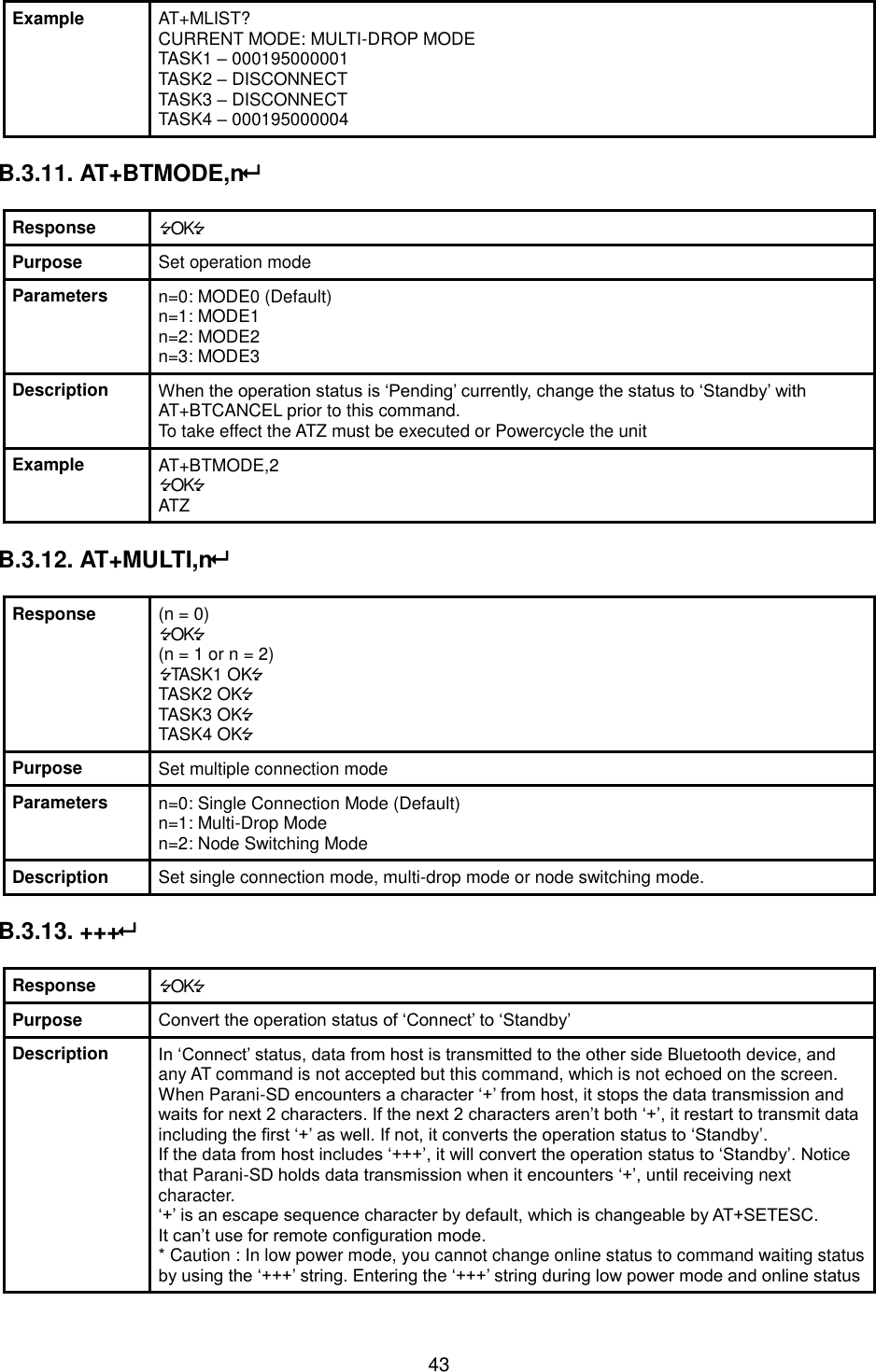
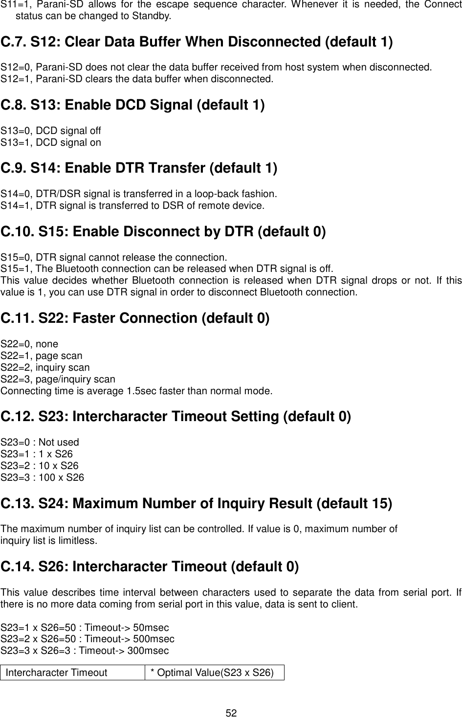
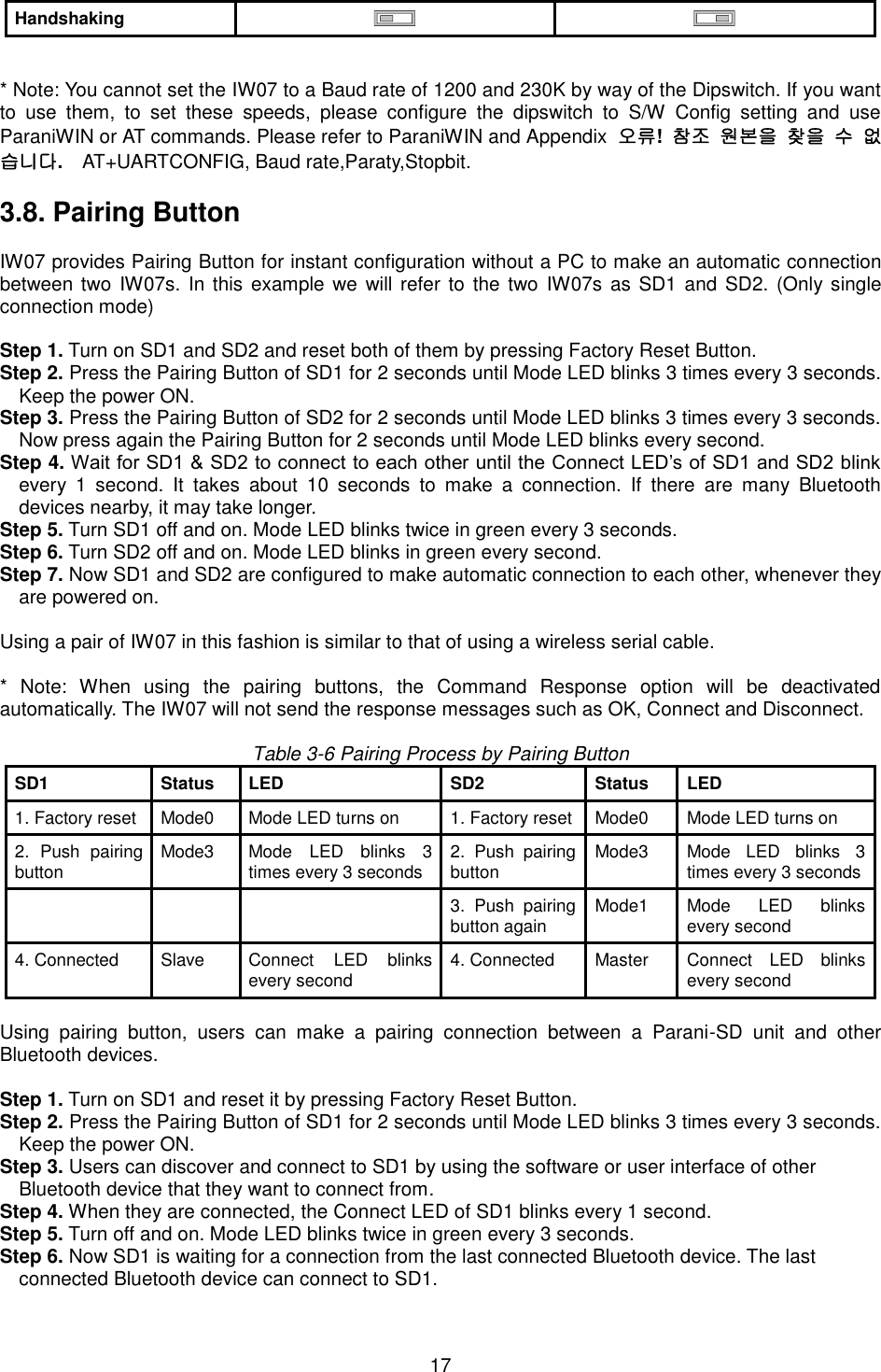
![24 Figure 3-8 Signal Strength Test The signal strength test shows LInkQuality and RSSI values. The closer LinkQuality is to 255 and RSSI is to 0, this means the IW07 has a good connection to the connected Bluetooth device. In general, the wireless connectivity is at its best within 10 meters. You can push the STOP button at anytime in order to terminate the signal strength test. The signal strength test will continue until the STOP button is pushed. If you close the ParaniWIN Window without pushing the STOP button, you must restart IW07 to terminate the test. Connection(in) icon will show the following window, which enables the IW07 to wait for a connection from another Bluetooth device. If the waiting time is set to 0, IW07 will continually wait for connection until [Cancel] button is clicked. Figure 3-9 Connection (in) Window](https://usermanual.wiki/Sena-Technologies/IW07/User-Guide-3233391-Page-24.png)
![35 6. Approval Information 6.1. IC This device complies with Industry Canada license-exempt RSS standard(s). Operation is subject to the following two conditions: (1) this device may not cause interference, and (2) this device must accept any interference, including interference that may cause undesired operation of the device. Le present appareil est conforme aux CNR d'Industrie Canada applicables aux appareils radio exempts de licence. L'exploitation est autorisee aux deux conditions suivantes : (1) l'appareil ne doit pas produire de brouillage, et. (2) l'utilisateur de l'appareil doit accepter tout brouillage radio electrique subi, meme si le brouillage est susceptible d'en compromettre le fonctionnement. This equipment should be installed and operated with minimum 20 cm between the radiator and your body. Cet équipement doit être installé et utilisé avec un minimum de 20 cm entre le radiateur et votre corps. This radio transmitter (Model: IW07) has been approved by Industry Canada to operate with the antenna types listed below with the maximum permissible gain indicated. Antenna types not included in this list, having a gain greater than the maximum gain indicated for that type, are strictly prohibited for use with this device. Cet émetteur radio (modèle: IW 07) a été approuvé par Industrie Canada pour fonctionner avec les types d'antennes répertoriés ci-dessous avec le gain maximal autorisé indiqué. Les types d'antennes non inclus dans cette liste, ayant un gain supérieur au gain maximal indiqué pour ce type, sont strictement interdits pour une utilisation avec cet appareil. Type Frequency[MHz] Max gain[dBi] Dipole antenna 2402~2480 5.70 6.2. CE Hereby, SENA TECHNOLOGIES.Inc Declares that this IW07 is in compliance with the essential requirements and other relevant provisions of directive 1999/5/EC.](https://usermanual.wiki/Sena-Technologies/IW07/User-Guide-3233391-Page-35.png)