Sena Technologies IW09 Bluetooth USB-Serial Adapter User Manual Contents
Sena Technologies,Inc. Bluetooth USB-Serial Adapter Contents
UserManual.wiki
>
Sena Technologies
>
IW09 User Manual
User Manual
Navigation menu
Upload a User Manual
Namespaces
Wiki Guide
HTML
PDF
Info
Views
User Manual
Discussion / Help
Navigation


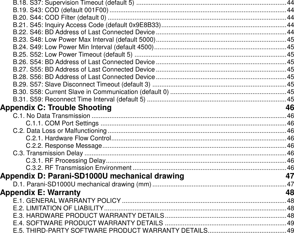
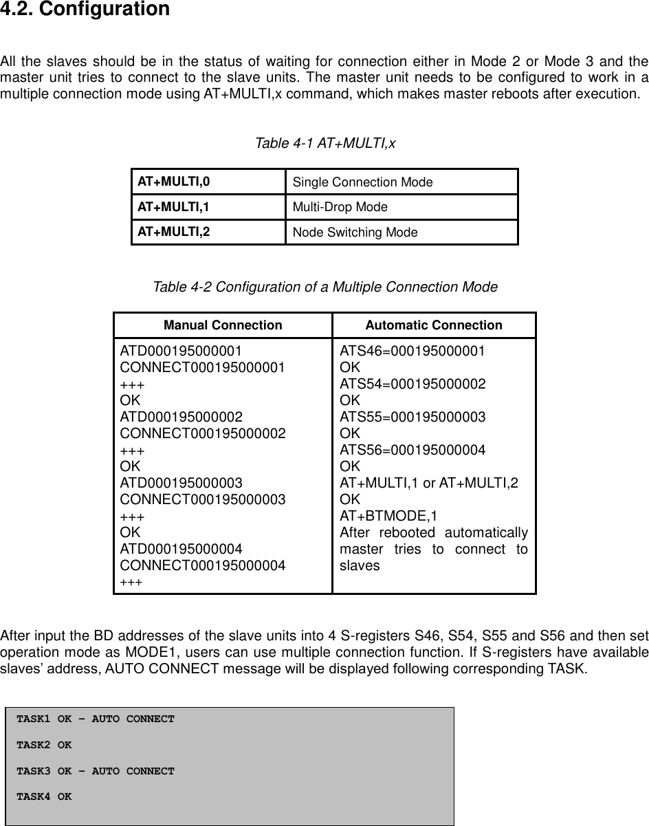
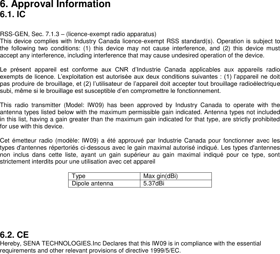
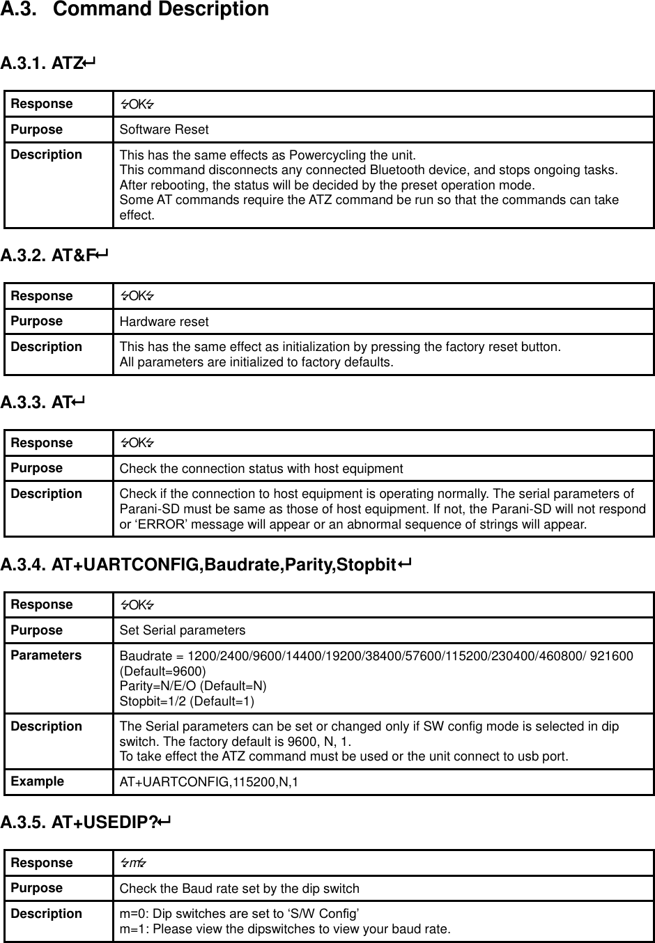
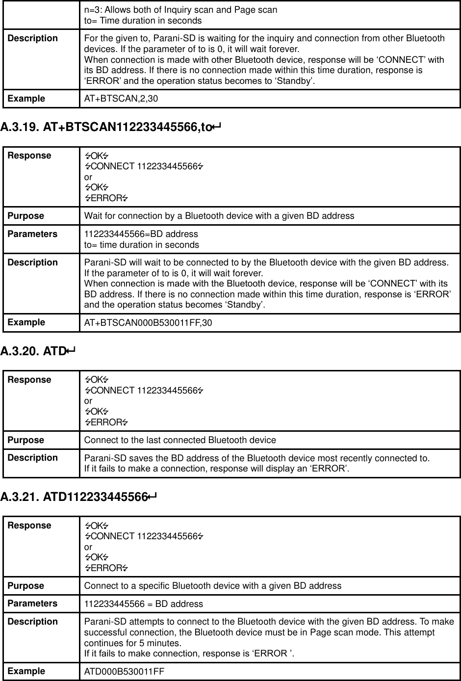
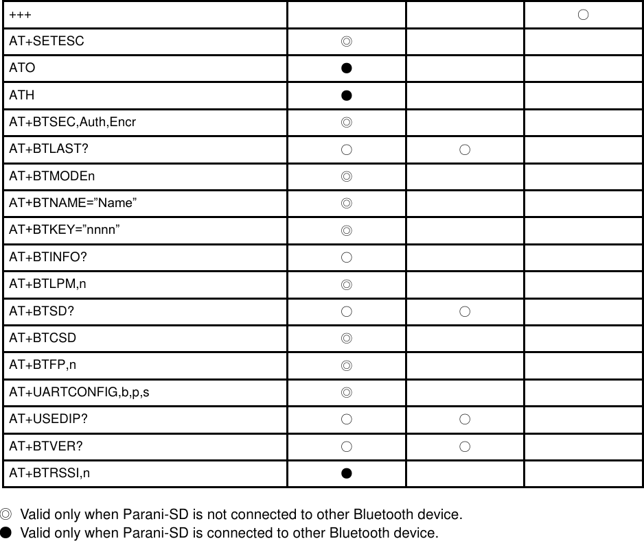
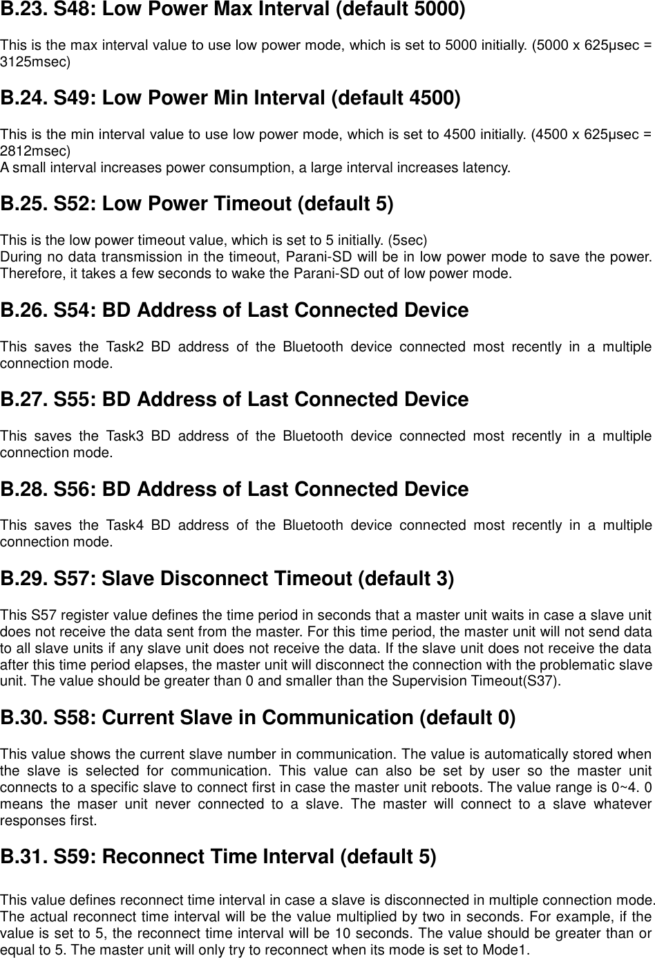
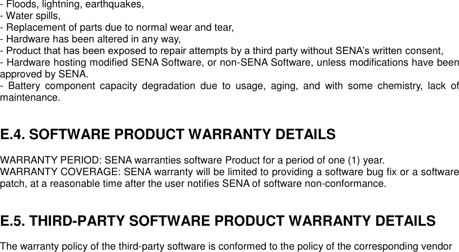
![Table 3-7 Pairing Process with other Bluetooth device by Pairing Button SD1 Status LED Other Bluetooth Device Status 1. Factory reset Mode0 Mode LED turns on 2. Push pairing button Mode3 Mode LED blinks 3 times every 3 seconds 3. Inquiry and connect to SD1 4. Connected Slave Connect LED blinks every second 4. Connected Master 3.9. Software and Utility This configuration software and utility for firmware update is included with the product, which also can be downloaded from http://www.senaindustrial.com Table 3-8 Configuration Software Software Purpose Operating System ParaniWIN Configuration MS Windows 98SE or Higher ParaniUpdater Firmware Update MS Windows 98SE or Higher 3.10. ParaniWIN ParaniWIN is a program that runs on Microsoft Windows for the configuration of Parani-SD1000U. Install ParaniWIN on your computer. Plug a Parani-SD1000U into the serial port of the computer and turn on the power. Run ParaniWIN. Figure 3-2 Serial Port Setting Set each option properly and click [Confirm]. If the settings of the Parani-SD1000U are different from the ParaniWin, an error message will pop up. If the Parani-SD1000U is in the status of connection, warning message will pop up. Then the current connection can be cancelled by [Disconnect] button on the main window.](https://usermanual.wiki/Sena-Technologies/IW09/User-Guide-3328944-Page-16.png)
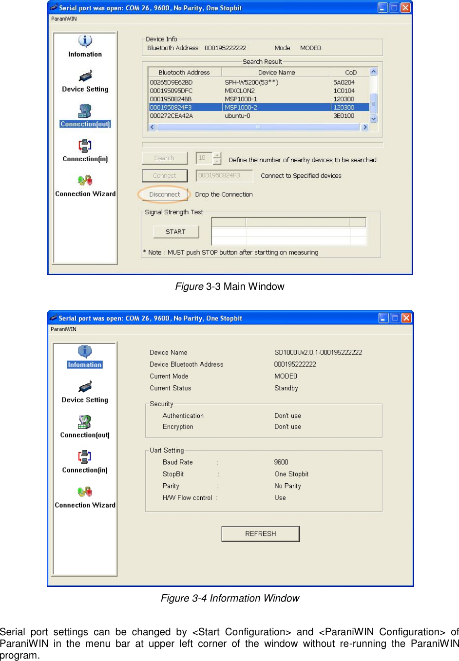
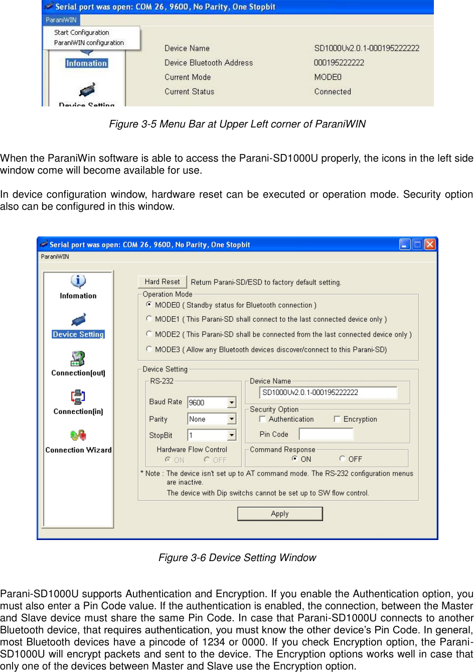
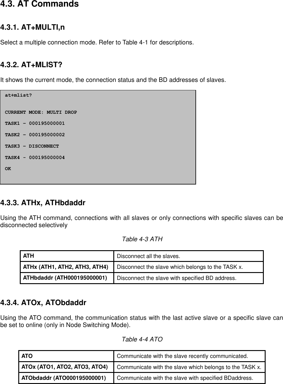
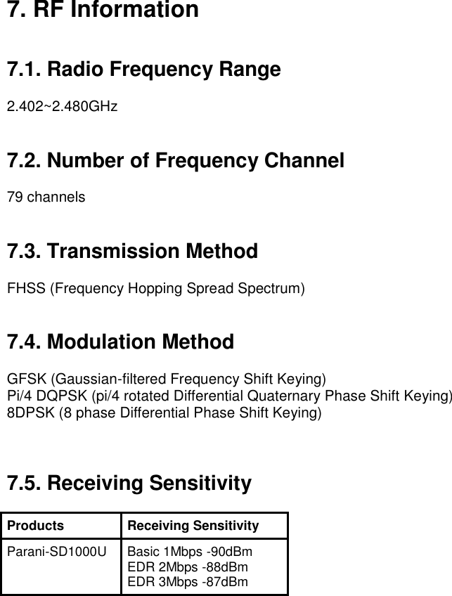
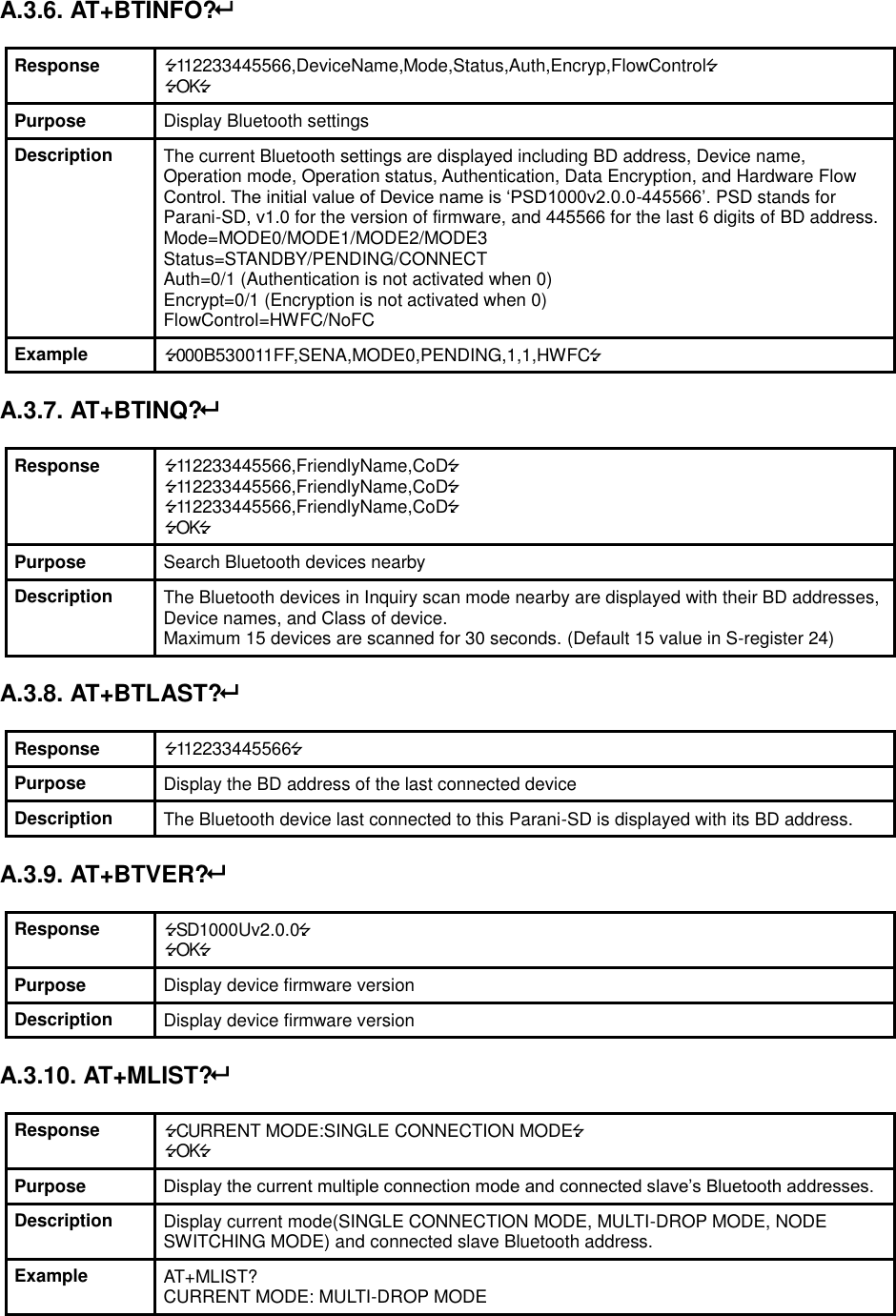
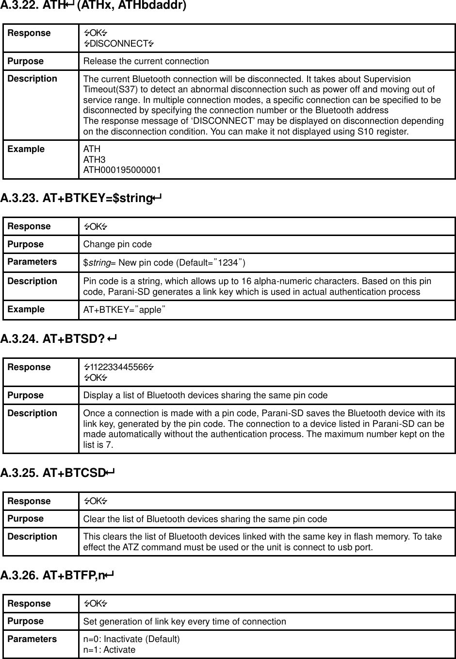
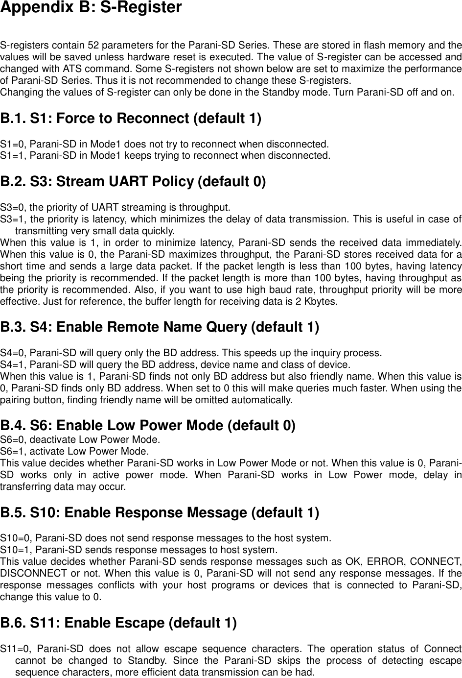
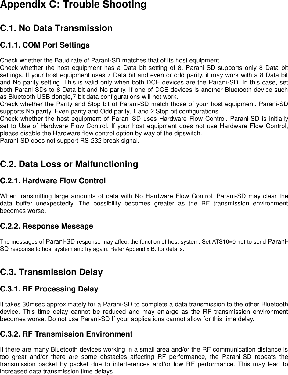
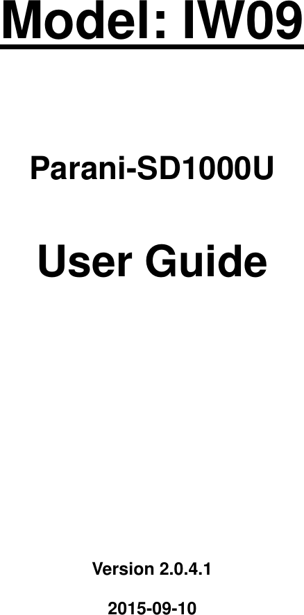
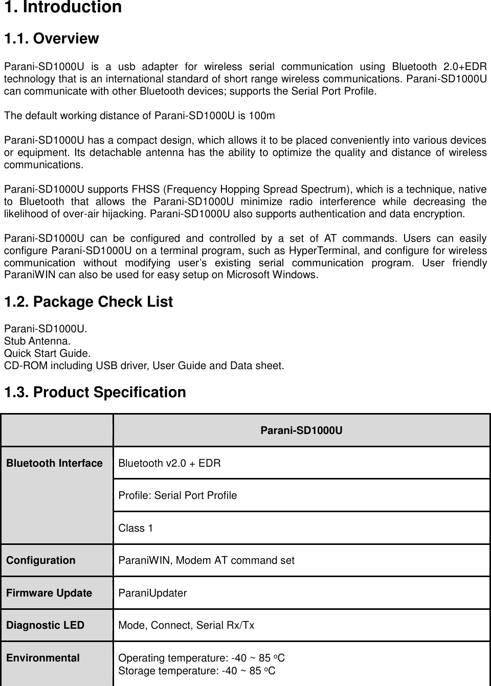
![Parani-SD1000U has 4 response messages, ‘OK’, ‘ERROR’, ‘CONNECT’, and ‘DISCONNECT’. In some cases, these responses can affect the host system unexpectedly. To prevent this, user can set the Command response to ON or OFF. For Parani-SD1000U, hardware flow control can be configured only by dip switch. And parity, stop bit can be configured only SW config mode. Thus H/W Flow Control option will not work in this case. When the dipswitch value isn’t ATcommand mode, the Baud Rate menu will be disabled. Click [Apply] button to apply any changes made to the Parani-SD1000U. Connection(out) icon will show the following window to search and connect other Bluetooth devices. Figure 3-7 Connection (out) Window Click [Search] button to search nearby Bluetooth devices. Once several Bluetooth devices has been found, select one of the devices and click the [Connect] button. The selected Bluetooth device must be discoverable and connectable. Click [Disconnect] button to cancel the connection. After the connection has been established, you will be able to test signal strength by pushing the START button.](https://usermanual.wiki/Sena-Technologies/IW09/User-Guide-3328944-Page-19.png)
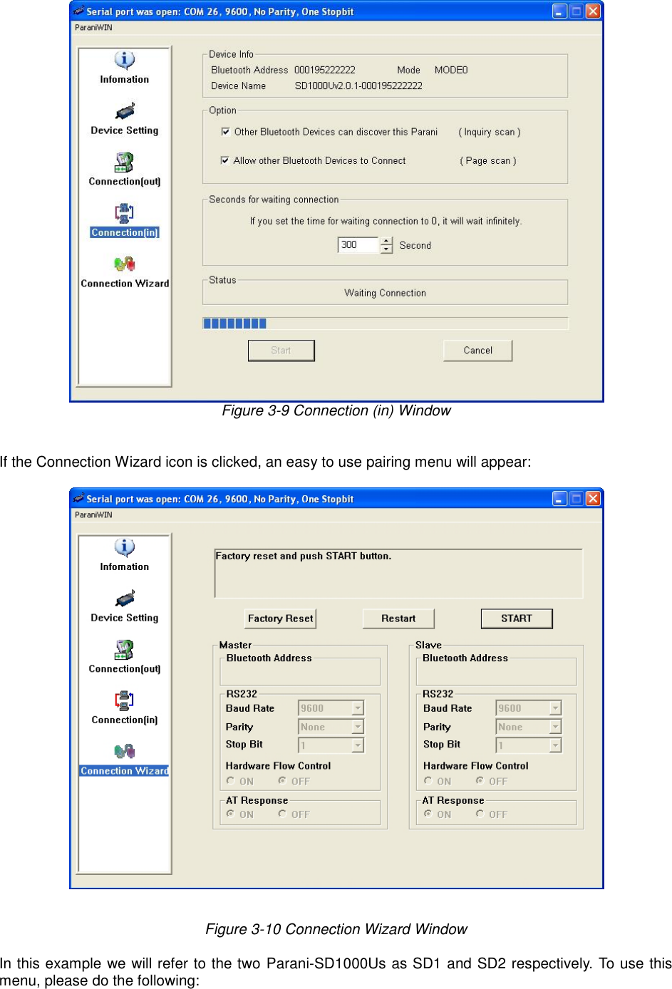
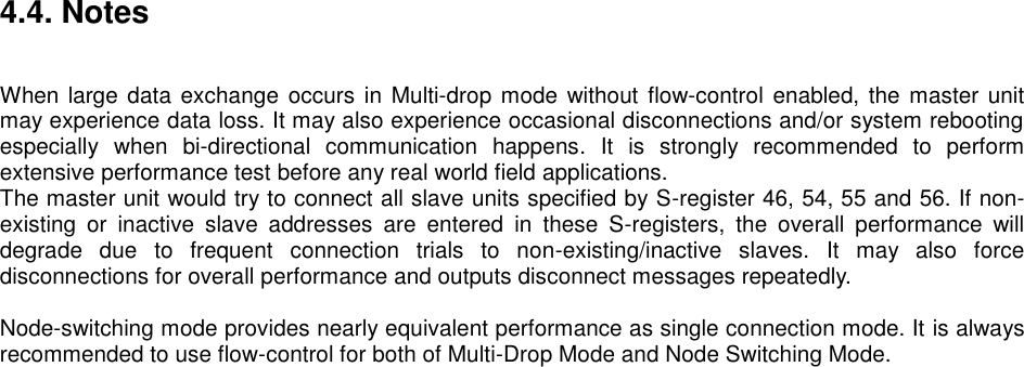
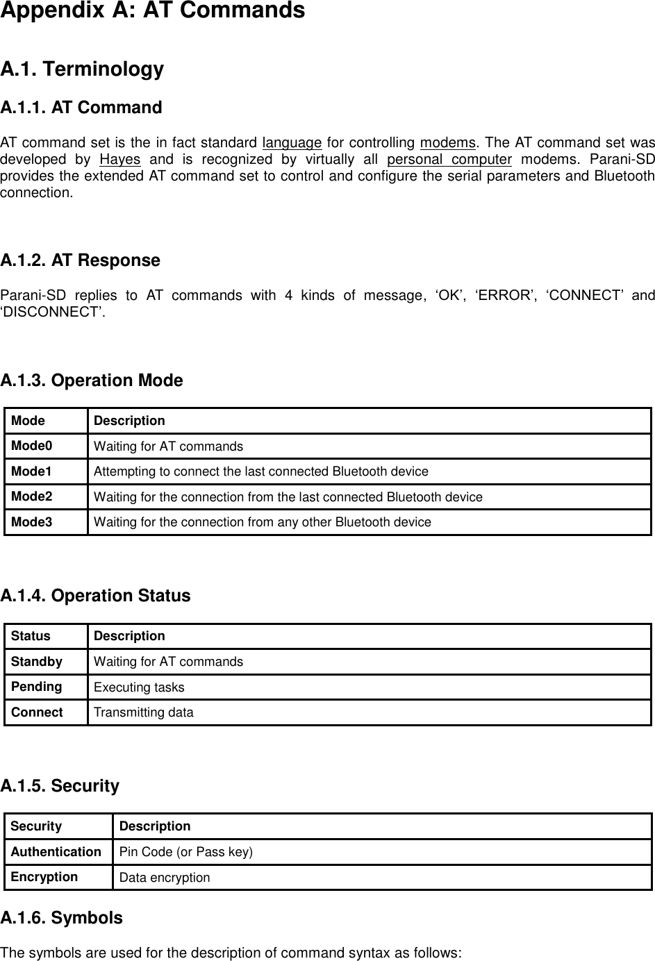
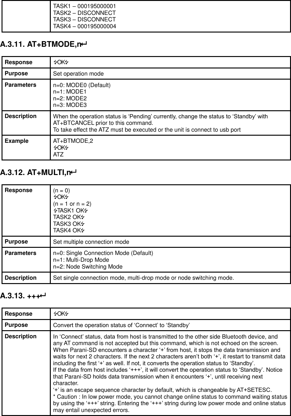
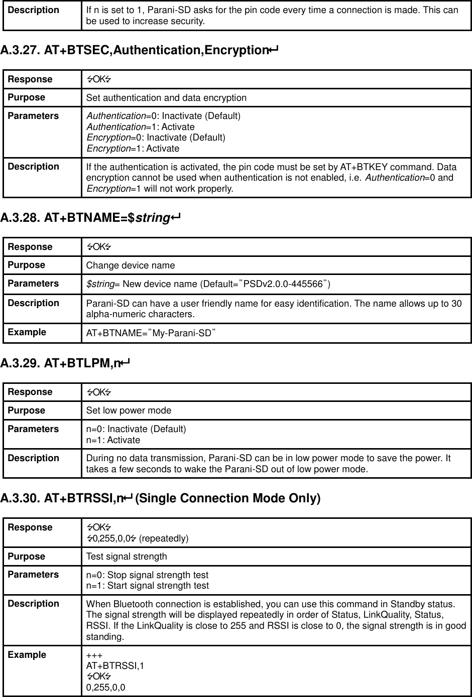
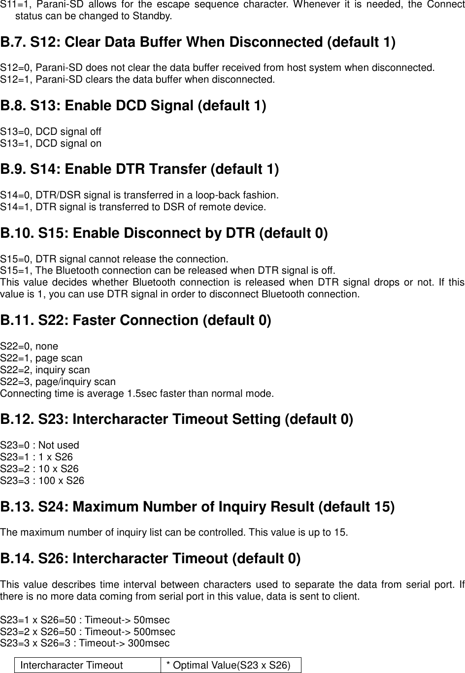
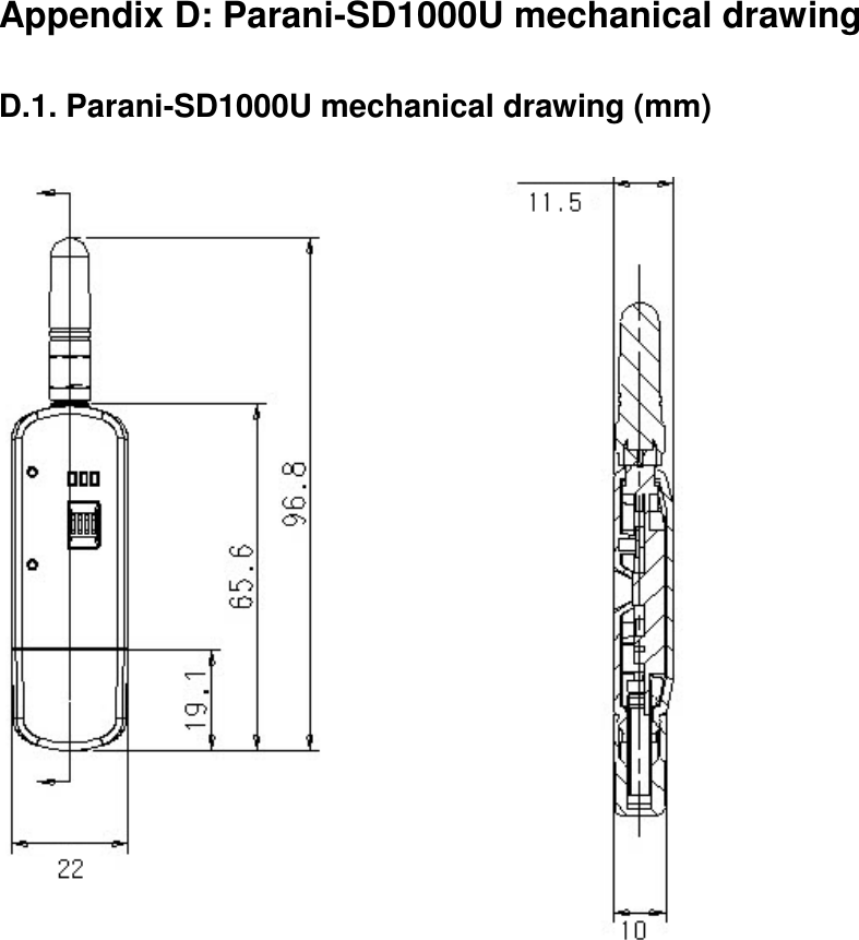
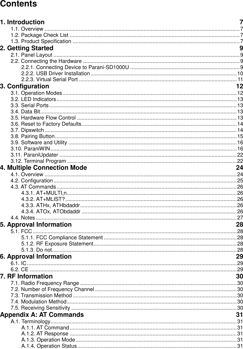
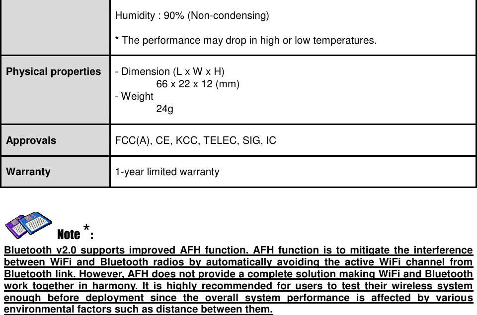
![Figure 3-8 Signal Strength Test The signal strength test shows LInkQuality and RSSI values. The closer LinkQuality is to 255 and RSSI is to 0, this means the Parani-SD1000U has a good connection to the connected Bluetooth device. In general, the wireless connectivity is at its best within 10 meters. You can push the STOP button at anytime in order to terminate the signal strength test. The signal strength test will continue until the STOP button is pushed. If you close the ParaniWIN Window without pushing the STOP button, you must restart Parani-SD1000U to terminate the test. Connection(in) icon will show the following window, which enables the Parani-SD1000U to wait for a connection from another Bluetooth device. If the waiting time is set to 0, Parani-SD1000U will continually wait for connection until [Cancel] button is clicked.](https://usermanual.wiki/Sena-Technologies/IW09/User-Guide-3328944-Page-20.png)