Sena Technologies LS100W Wireless serial device server (AP) User Manual
Sena Technologies,Inc. Wireless serial device server (AP)
UserManual.wiki
>
Sena Technologies
>
LS100W User Manual
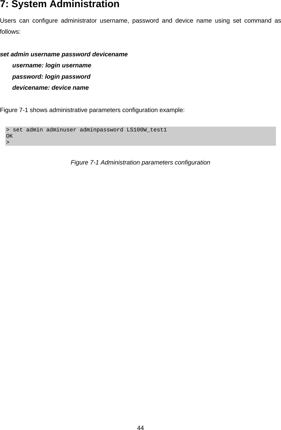
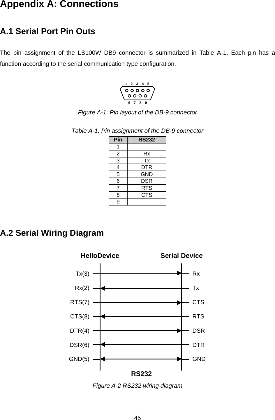
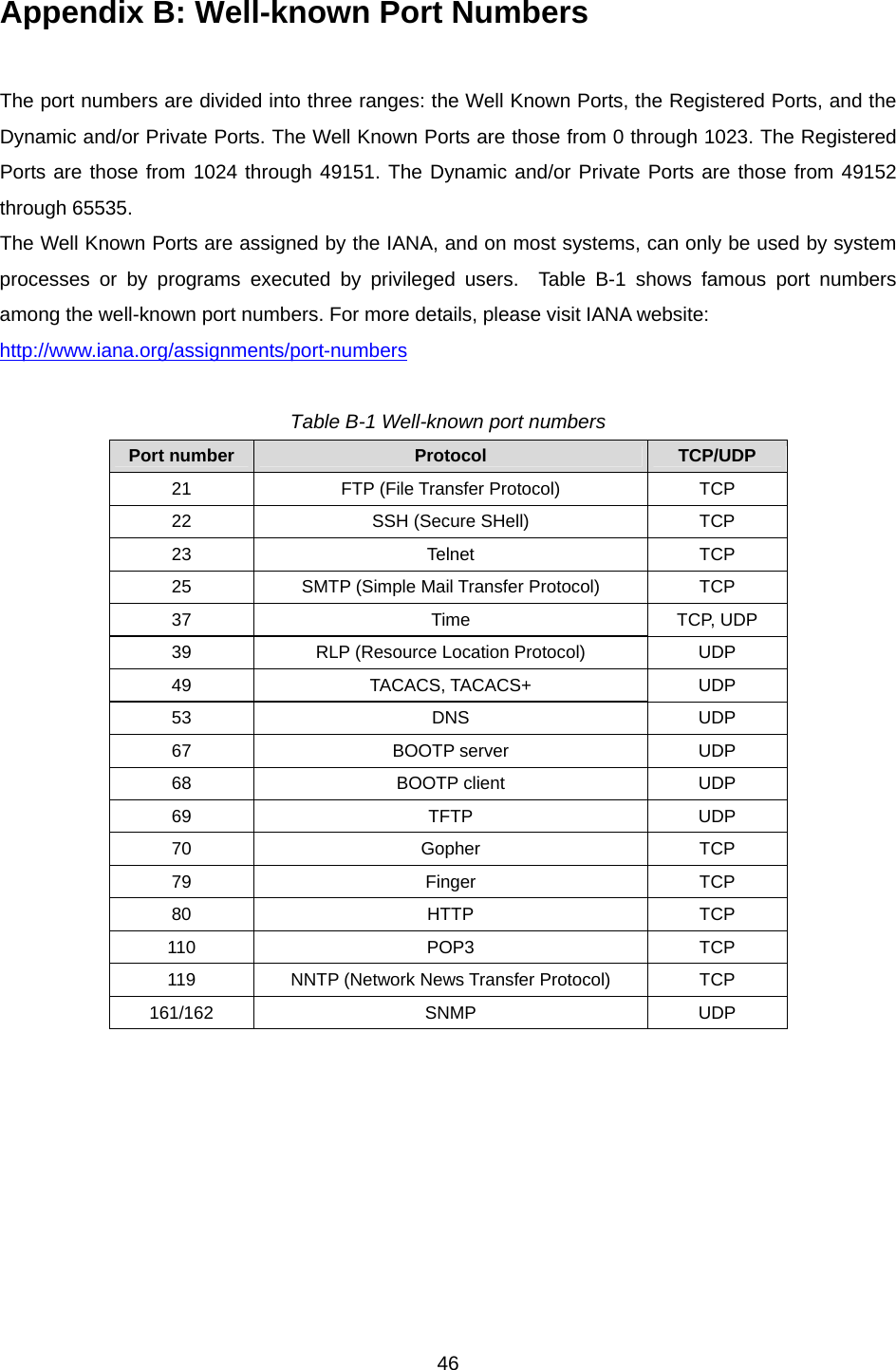
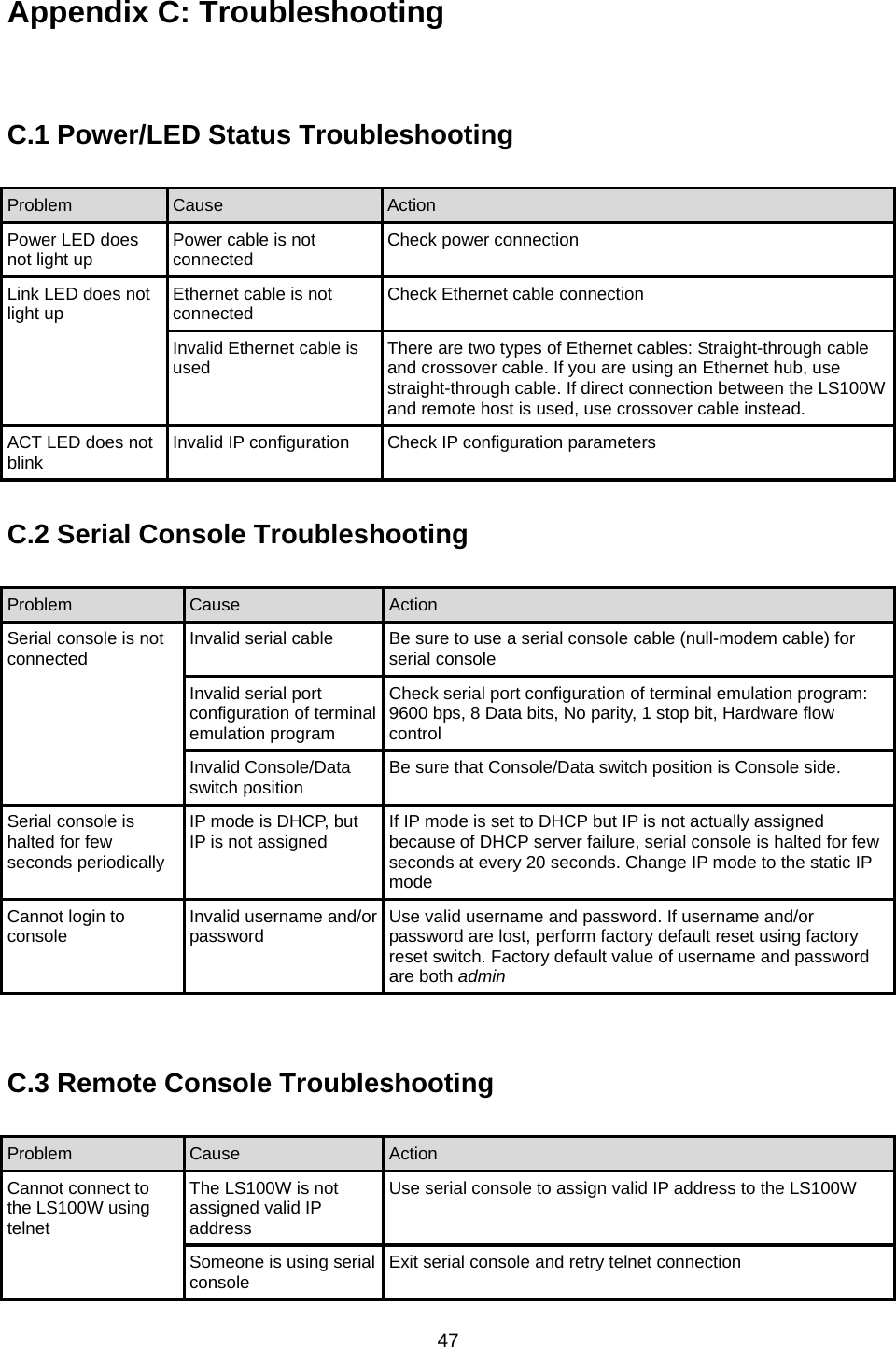
Users Manual
Navigation menu
Upload a User Manual
Namespaces
Wiki Guide
HTML
PDF
Info
Views
User Manual
Discussion / Help
Navigation

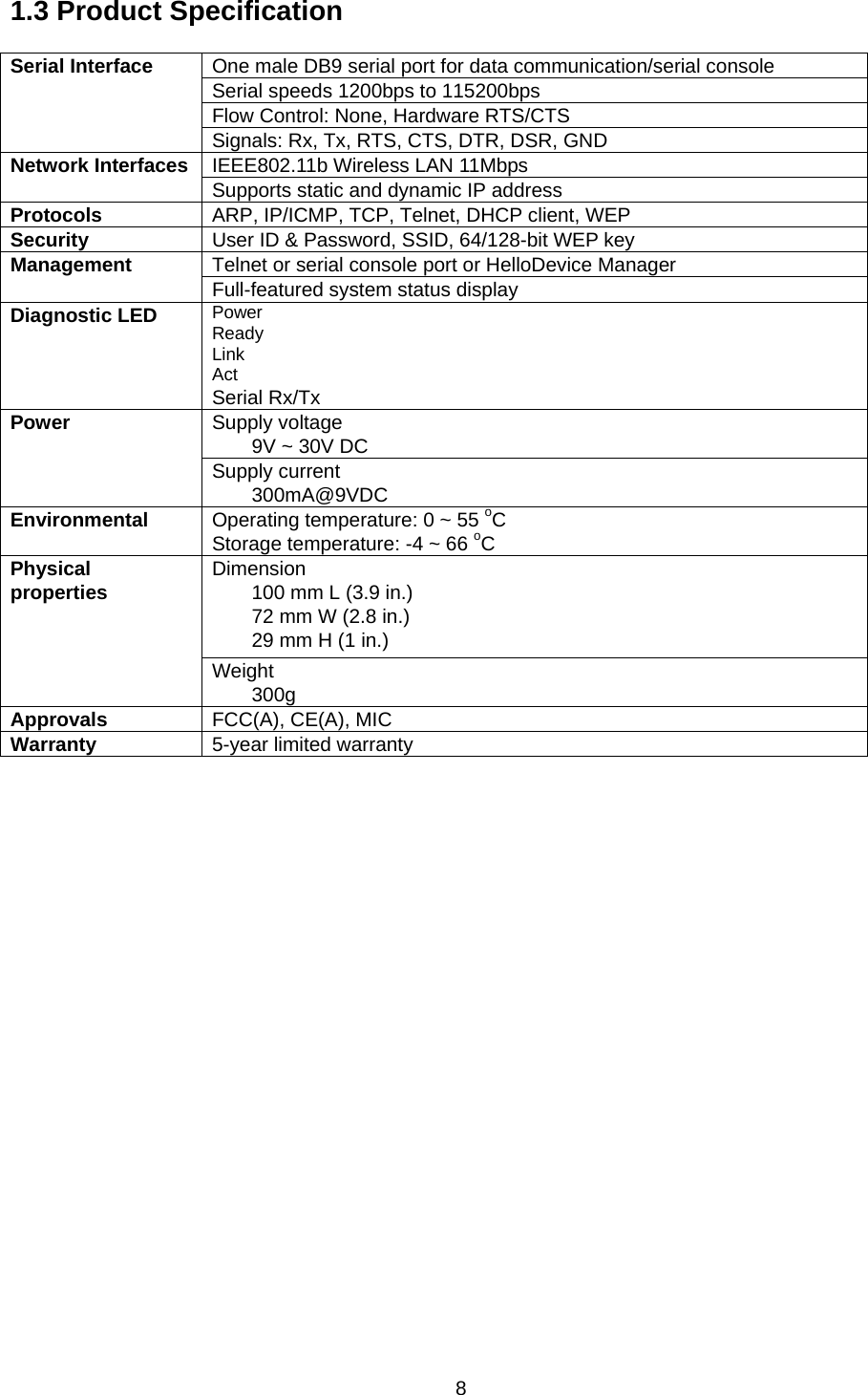
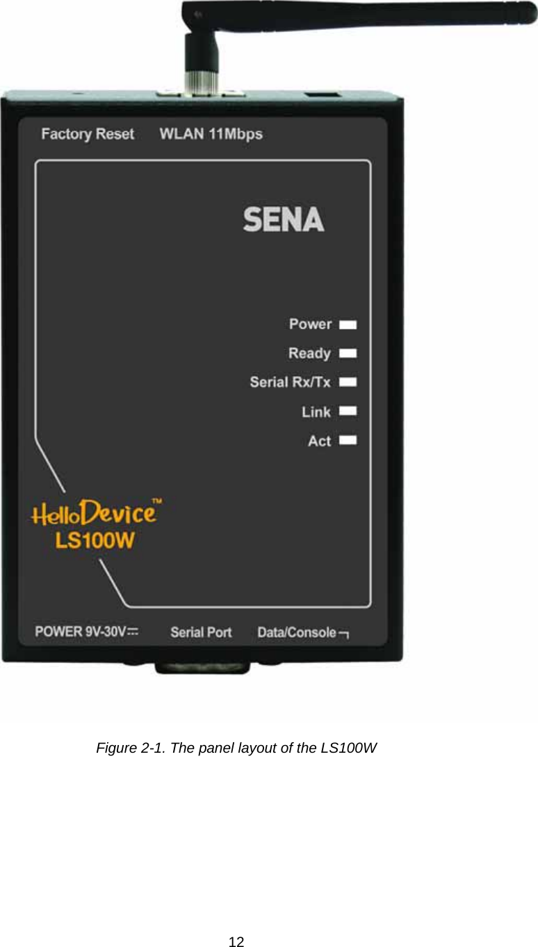
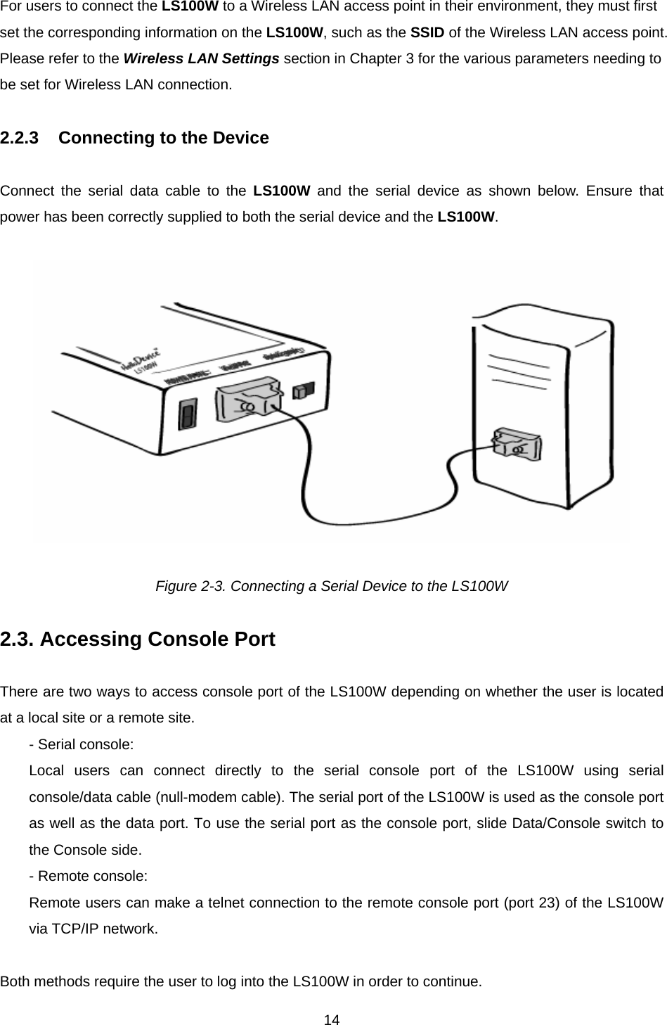
![132.2 Connecting the Hardware This section describes how to connect the LS100W to the serial device for initial testing. - Connect a power source to the LS100W. - Connect the LS100W to a serial device through serial data cable. 2.2.1 Connecting the Power Connect the power jack to the LS100W power plug using the DC power adapter included in the package. If power is supplied properly, the [Power] LED lamp on the LS100W front panel will remain solid red. Figure 2-2. Connecting the Power to the LS100W 2.2.2 Connecting to the Wireless LAN There is built-in 802.11b Wireless LAN module in the LS100W. When power is connected correctly, the module will automatically search for the Wireless LAN access point, and then try to connect to the LAN access point. If the Wireless LAN cable is properly connected to the Wireless LAN access points, the LS100W will have a valid connection to the Wireless LAN network and indicates that valid connection with the following indications: - The [Link] LED lamp on the LS100W front panel remains solid orange. - The [Act] LED lamp on the LS100W front panel continuously blinks to indicate the transfer of the incoming and outgoing Wireless LAN packets.](https://usermanual.wiki/Sena-Technologies/LS100W/User-Guide-572937-Page-13.png)
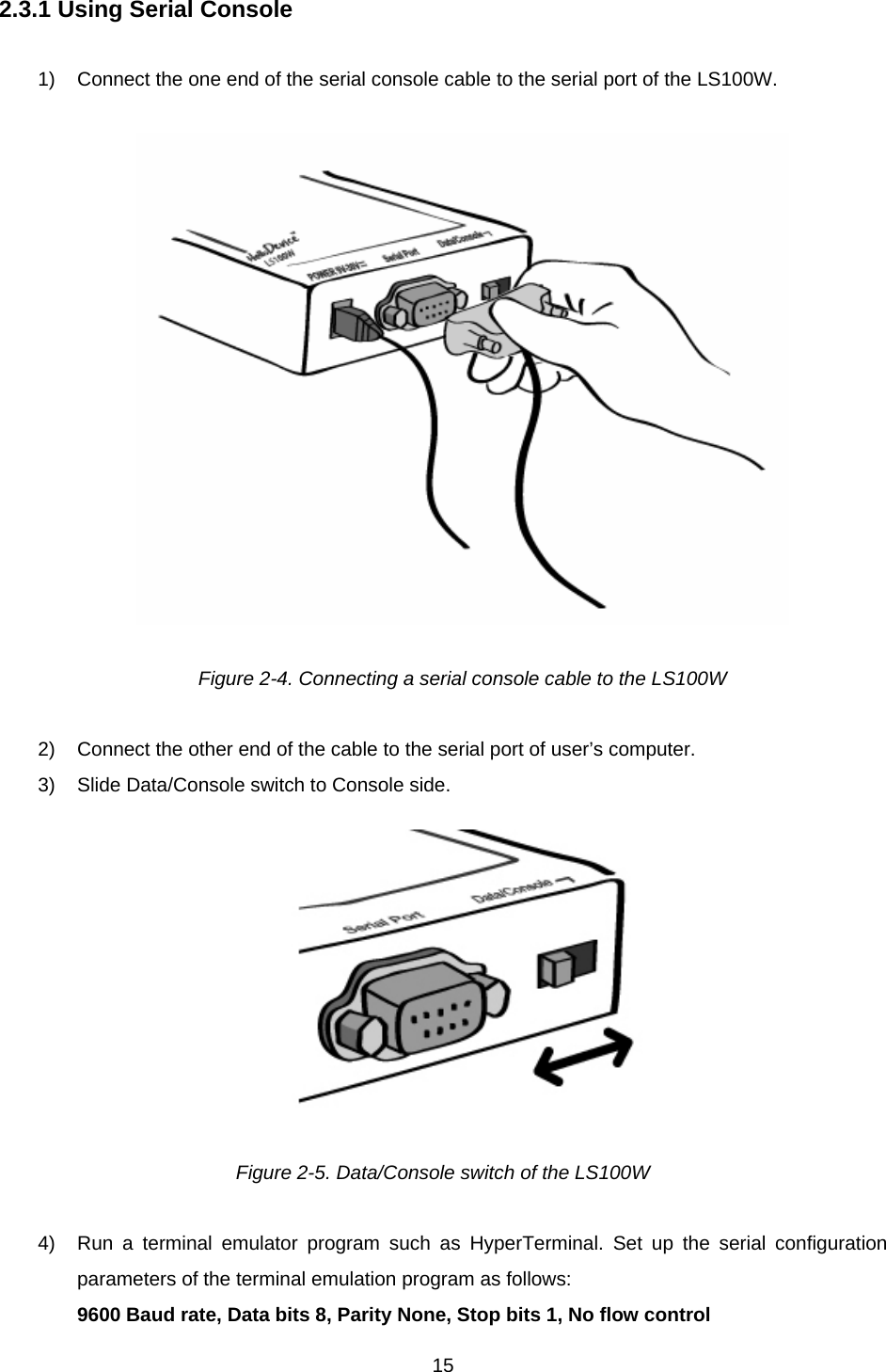
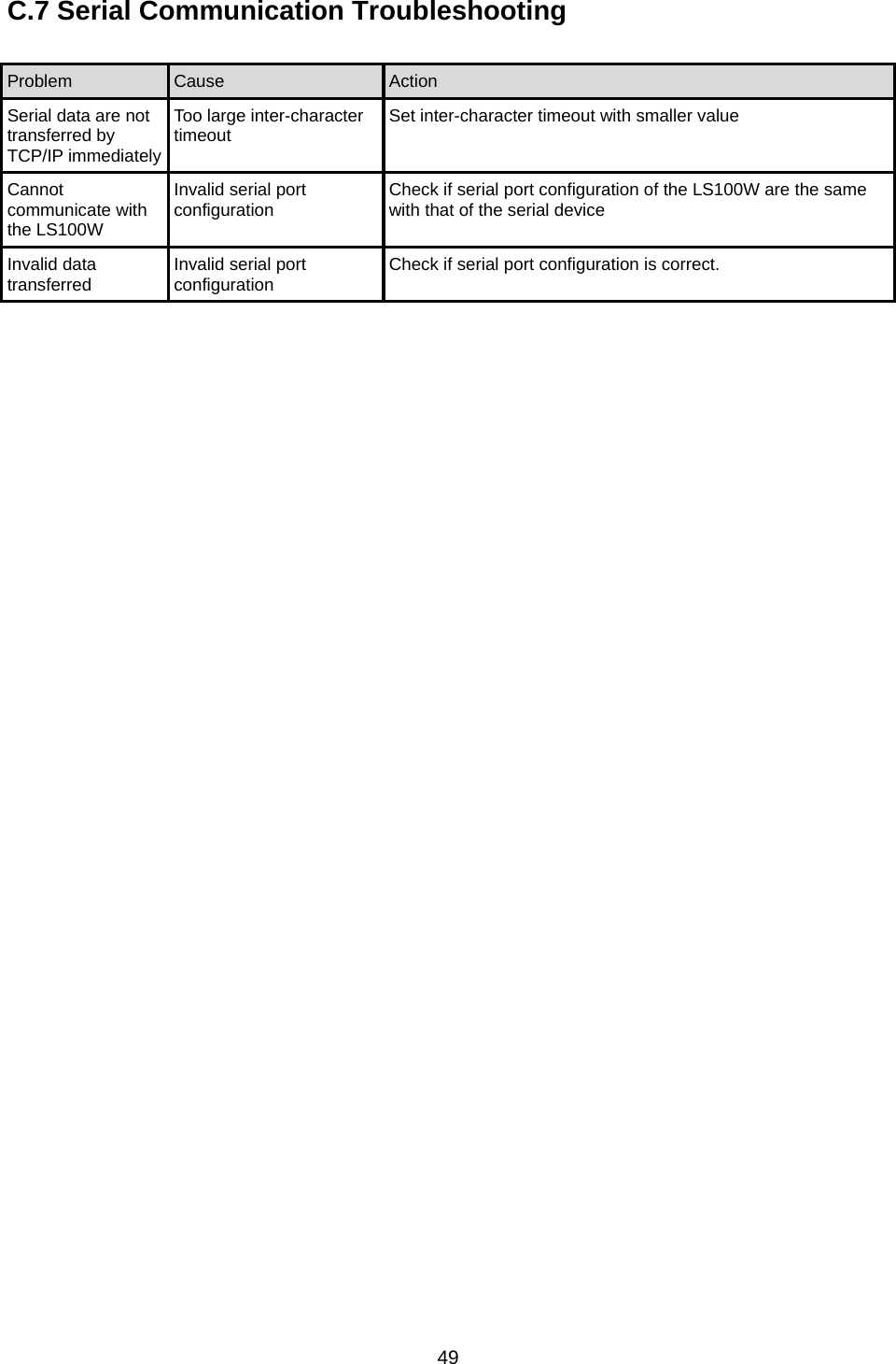
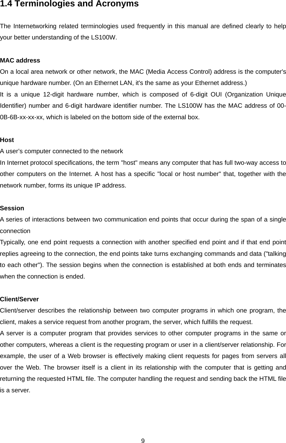
![165) Press [ENTER] key. 6) Type the user name and password to log into the LS100W. A factory default setting of the user name and password are both admin. 7) If the user logged into the LS100W successfully, command prompt screen will appear on the computer as shown in Figure 2-6. login: admin password: ***** Type 'help' to get command usages > help set group par1 [par2 ...] + <CR> - group = 'ip','host','wlan','serial' or 'admin' - par1 ... = configuration parameters. Use * to keep a parameter's value get [group] + <CR> - group = 'ip','host','wlan','serial','admin' or 'status' - If group is specified, shows settings of the group. - If group is omitted, shows settings of all groups. help [group] + <CR> - If group is omitted, shows this screen. - If group is specified, shows 'set' command usage of the group. factorydefault [option] + <CR> - if option is omitted, all parameters are set with factory default values. - if option='-ip', all parameters except IP settings are set with factory default values. save + <CR> - Save changes exit + <CR> - Exit without rebooting the device reboot + <CR> - Exit and reboot the device > Figure 2-6. The LS100W console screen From the command prompt screen, users can set, get and save configuration parameter values using ‘set’, ‘get’ and ‘save’ command. Users also can exit the console or reboot the device using ‘exit” and ‘reboot’ command. The usage of the commands can be found using ‘help’ command. For command usages description, please refer to section 2.4 Command usage. 2.3.2 Using Remote Console The LS100W provides remote console feature via telnet as well as serial console so that users can access the LS100W at remote site for configuration and monitoring purpose. The IP address of the LS100W must be known before users can access the remote console port. The port number for the remote console is 23, which is a TCP port number assigned for Telnet. Only one user can log into the remote console or serial console at a time. If the serial console is established while a remote console is established, current remote console will be halted and no more remote console will be established until serial console is finished. To access remote console of the LS100W, please use the step as follows:](https://usermanual.wiki/Sena-Technologies/LS100W/User-Guide-572937-Page-16.png)
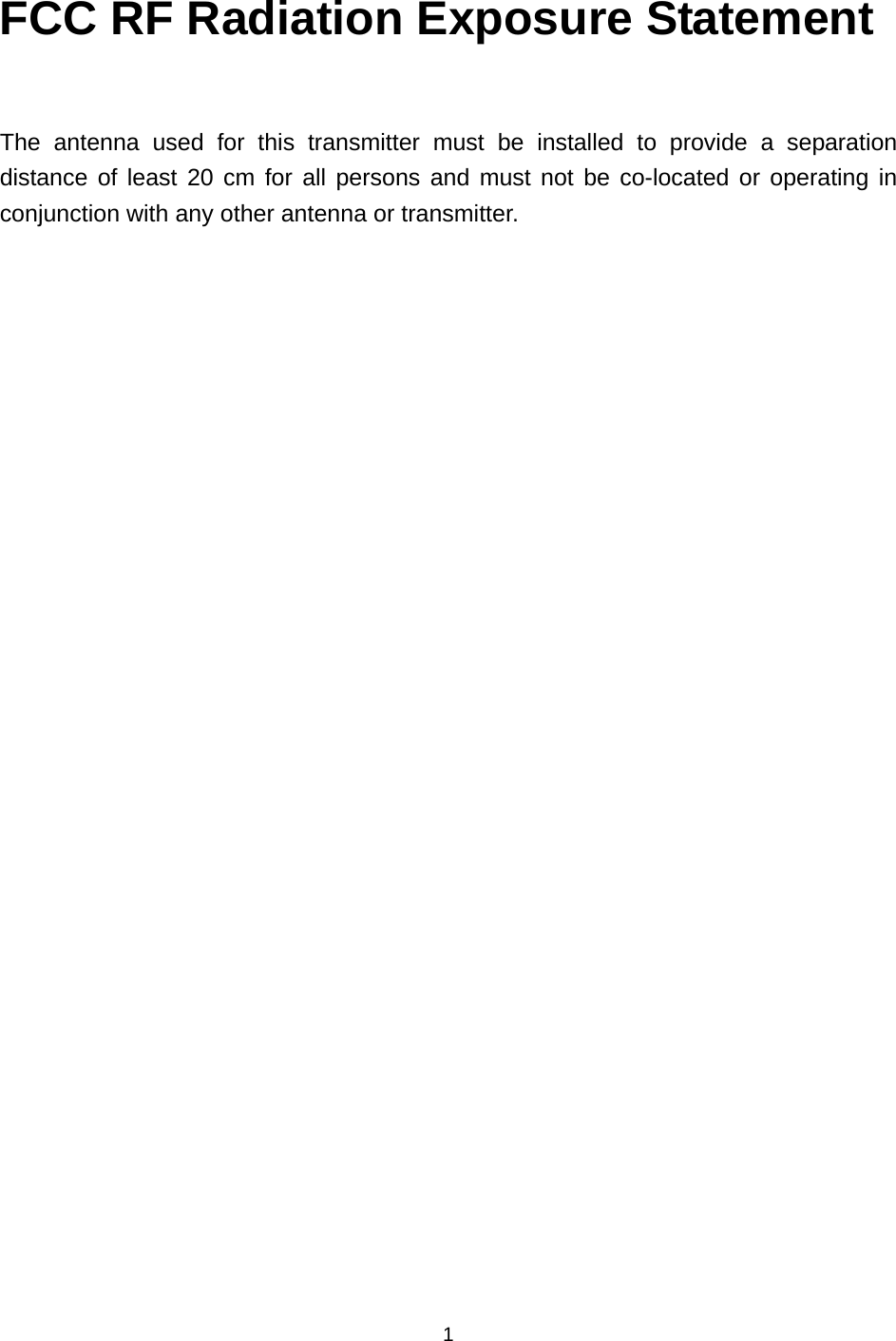
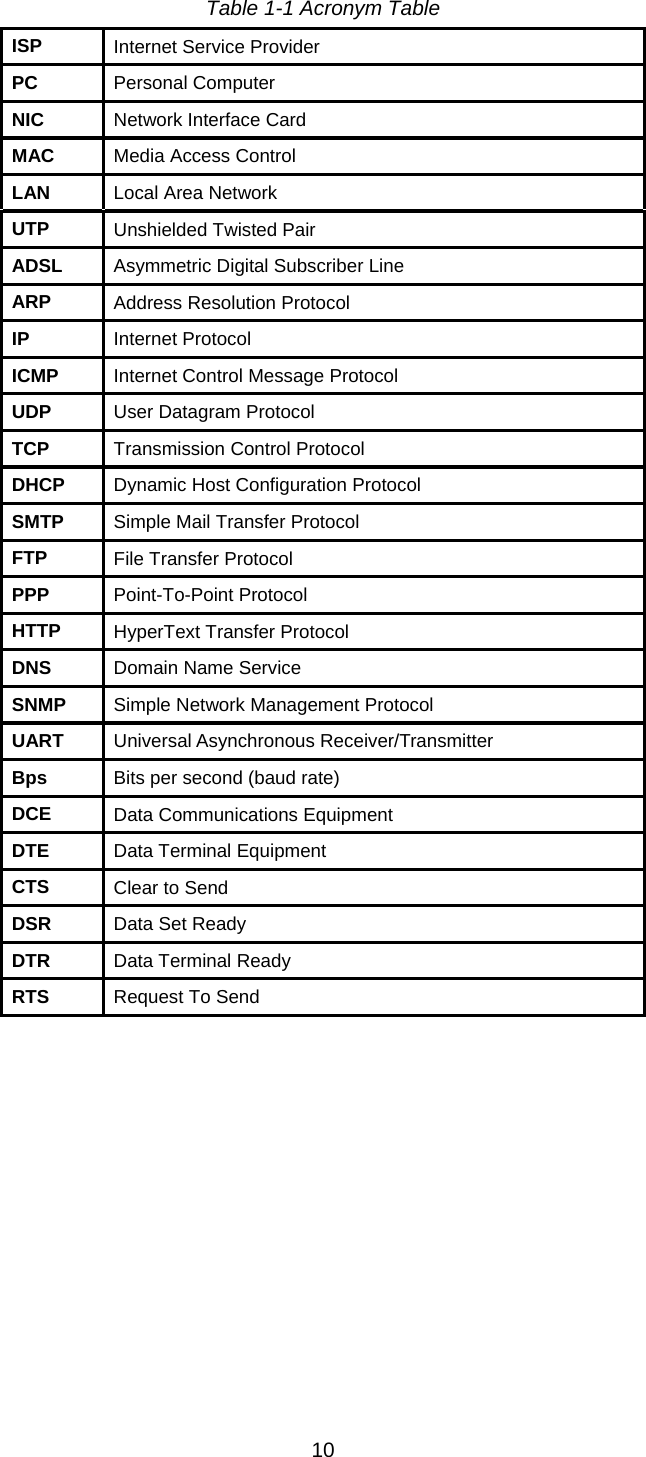
![171) Run a telnet program or a program that supports telnet functions such as TeraTerm-Pro or HyperTerminal. The target IP address and the port number should be those of the LS100W. If required, specify the port number as 23. Type the following command in the command line interface of your computer. telnet 192.168.1.254 Or run a telnet program with parameters as follows. Figure 2-7 Telnet program set up example 2) The user has to log into the LS100W. Type the user name and password. A factory default setting of the user name and password are both admin. 3) If the user logged into the LS100W successfully, the same command prompt screen as the one of serial console will be displayed. The user can set, get, save configuration parameters and exit console, reboot the device as like the serial console. 4) If serial console or the other remote consoles are connected already, new console will not be established at all. 2.4 Command Usage The LS100W provides several simple commands for configuration and control of the LS100W. Table 2-2 summarizes command set which LS100W supports. Table 2-2 LS100W command set summary Command Description Result set group par1 [par2 ...] + <CR> Set configuration parameters - group = 'ip', 'host', 'serial' or 'admin' - par1 ... = configuration parameters. Use * to keep a parameter's value If success, “OK” + <CR> + <LF> If error “ERROR” + <CR> + <LF>](https://usermanual.wiki/Sena-Technologies/LS100W/User-Guide-572937-Page-17.png)
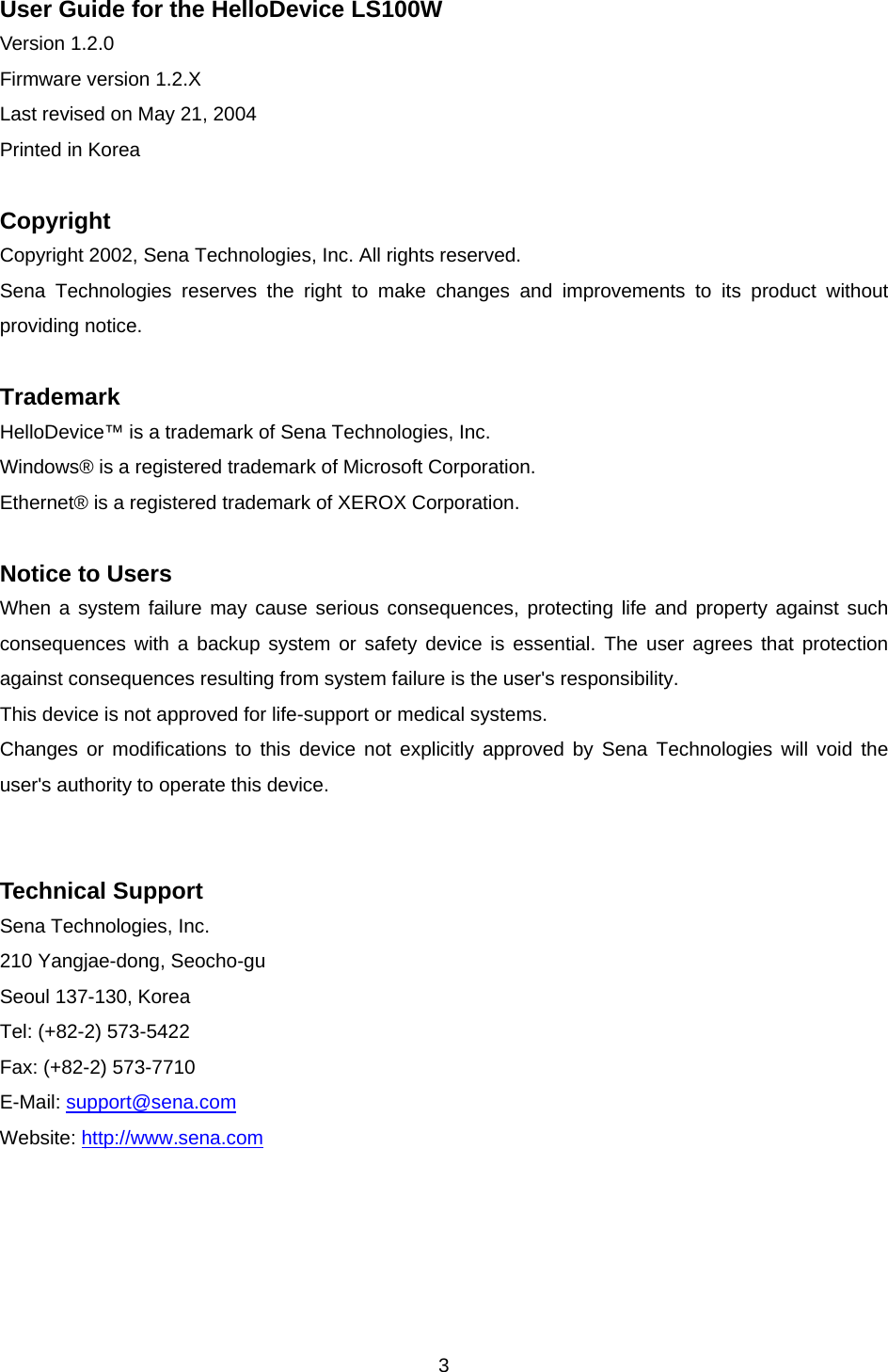
![18get [group] + <CR> Get configuration parameter values - group = 'ip', 'host', 'serial', 'admin' or 'status' - If group is specified, shows settings of the group. - If group is omitted, shows settings of all groups.Parameter value display help [group] + <CR> Shows command usage screen. - If group is omitted, shows help screen. - If group is specified, shows 'set' command usage of the group. Help message display factorydefault [option] + <CR> Restore factory default values - if option is omitted, all parameters are set with factory default values. - if option='-ip', all parameters except IP settings are set with factory default values. If success, “OK” + <CR> + <LF> If error “ERROR” + <CR> + <LF>save + <CR> Save changes If success, “OK” + <CR> + <LF> If error “ERROR” + <CR> + <LF>exit + <CR> Exit without rebooting the device (changes are not applied) If success, “OK” + <CR> + <LF> If error “ERROR” + <CR> + <LF>reboot + <CR> Exit and reboot the device None 2.4.1 ‘set’ Command With ‘set’ command, users can configure parameter values of the LS100W for each environment. Basic ‘set’ command usage is as follows: set group par1 [par2 ...] + <CR> where, group = 'ip','host', ‘wlan’,'serial' or 'admin' par1 par2 ... = configuration parameters. Use * to keep a parameter's value The ‘group’ is the category where the parameters should be entered. For example, if users want to set parameters related to the IP configuration, use set command as shown in the Figure 2-8. > set ip static 192.168.1.100 255.255.255.0 192.168.1.1 OK > Figure 2-8 IP configuration example screen In the above example, the first parameter ‘ip’ indicates that the following parameters are IP configuration parameters. The second parameter ‘static’ indicates that the LS100W will use static IP address of the third parameter ‘192.168.1.100’. The fifth parameter indicates the subnet mask and the](https://usermanual.wiki/Sena-Technologies/LS100W/User-Guide-572937-Page-18.png)
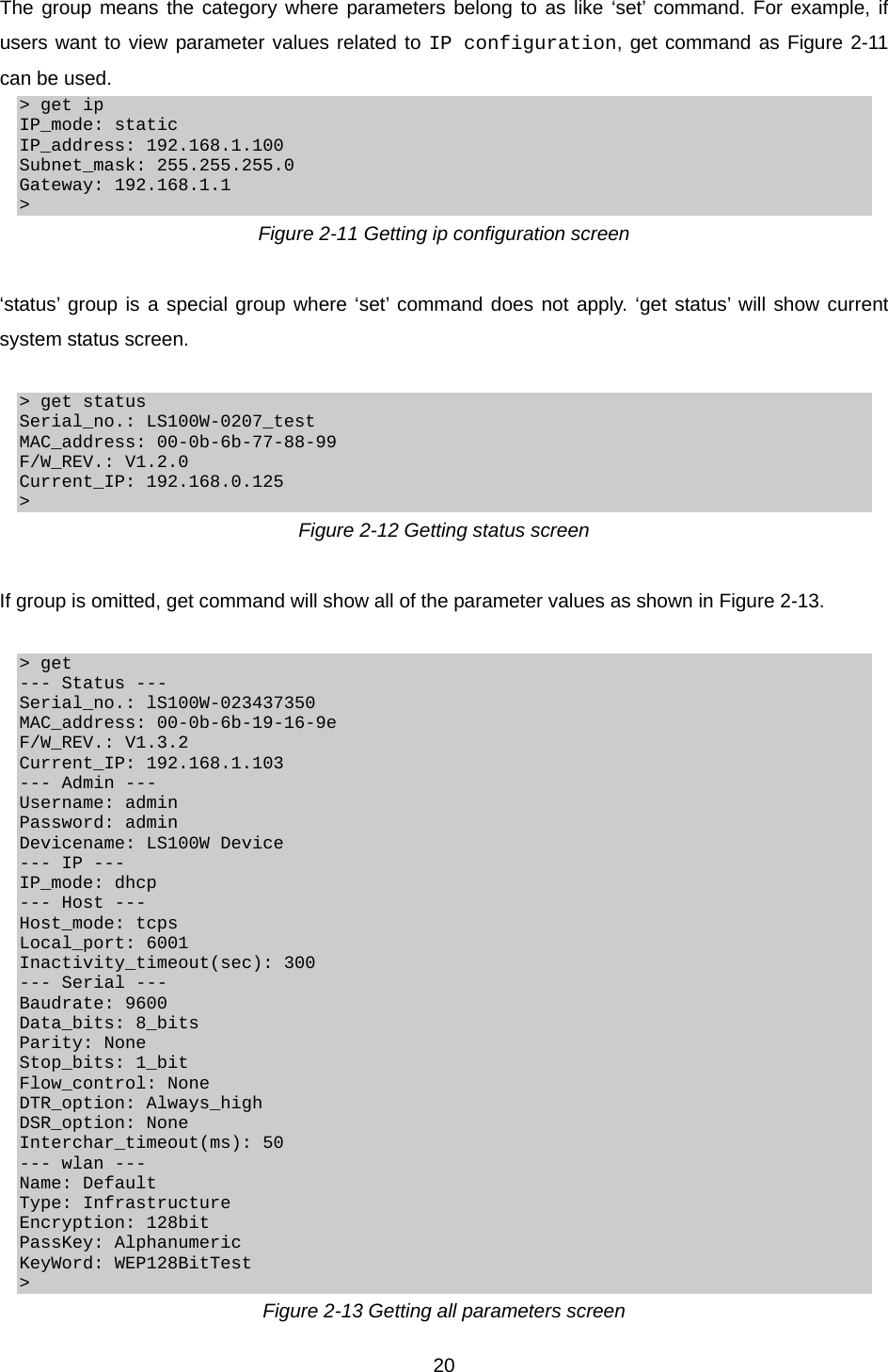
![19next indicates the default gateway IP address. If users want to change only one of the parameters of the group, users can omit trailing parameters and/or can use ‘*’ to keep a parameter value. The screen below will show how to change subnet mask only without changing IP address and gateway IP address. > set ip static * 255.255.0.0 OK > Figure 2-9 Changing only one parameter value example Command usage of ‘set’ will differ depending on the groups. Each ‘set’ command usage of the group can be found using ‘help group’ command. For example, if users want to know how to use ‘set’ command to configure IP configuration, typing ‘help ip’ + <CR> will show ‘set’ command usage for the IP configuration as shown in Figure 2-10. > help ip set ip ipmode par1 par2 ... - ipmode: static=Static IP / dhcp=DHCP / pppoe=PPPoE - parameters: if ipmode = static, par1 = IP address, par2 = subnet mask, par3 = gateway if ipmode = dhcp, no parameters required if ipmode = pppoe, par1 = PPPoE username, par2 = PPPoE password > Figure 2-10 Help screen example Note: The changed values will not take effect until ‘save’ and ‘reboot’ commands are invoked. For more details, please refer to section 2.4.5 ~ 2.4.7. 2.4.2 ‘get’ Command With ‘get’ command, users can view the current parameter values and status of the LS100W. Basic ‘get’ command usage is as follows: get [group] + <CR> where, group = 'ip','host',’wlan’,'serial', 'admin' or 'status' - If group is specified, shows settings of the group. - If group is omitted, shows settings of all groups.](https://usermanual.wiki/Sena-Technologies/LS100W/User-Guide-572937-Page-19.png)
![212.4.3 ‘help’ Command With ‘help’ command, users can find command usage help in the console screen. Basic command usage is as follows: help [group] + <CR> where, if group is omitted, overall help screen will be displayed if group is specified, ‘set’ command usage of specified group will be displayed. Figure 2-14 shows help screen when no group is specified while Figure 2-16 shows help screen with ‘ip’ group specified. > help set group par1 [par2 ...] + <CR> - group = 'ip','host',’wlan’,'serial' or 'admin' - par1 ... = configuration parameters. Use * to keep a parameter's value get [group] + <CR> - group = 'ip','host',’wlan’,'serial','admin' or 'status' - If group is specified, shows settings of the group. - If group is omitted, shows settings of all groups. help [group] + <CR> - If group is omitted, shows this screen. - If group is specified, shows 'set' command usage of the group. factorydefault [option] + <CR> - if option is omitted, all parameters are set with factory default values. - if option='-ip', all parameters except IP settings are set with factory default values. save + <CR> - Save changes exit + <CR> - Exit without rebooting the device reboot + <CR> - Exit and reboot the device Figure 2-14 Help screen > help ip set ip ipmode par1 par2 ... - ipmode: static=Static IP / dhcp=DHCP / pppoe=PPPoE - parameters: if ipmode = static, par1 = IP address, par2 = subnet mask, par3 = gateway if ipmode = dhcp, no parameters required if ipmode = pppoe, par1 = PPPoE username, par2 = PPPoE password Figure 2-15 Help screen with ‘ip’ group specified](https://usermanual.wiki/Sena-Technologies/LS100W/User-Guide-572937-Page-21.png)
![222.4.4 ‘factorydefault’ Command With ‘factorydefault’ command, users can load factory default parameter values in console. Command usage of ‘factorydefault’ is as follows: factorydefault [option] + <CR> where, - if option is omitted, all parameters are set with factory default values. - if option='-ip', all parameters except IP settings are set with factory default values. Loaded values are not saved until ‘save’ command invoked. After ‘factorydefault” command, ‘save’ and ‘reboot’ commands are required for changes to take effect. > factorydefault (or factorydefault –ip) OK > save OK > reboot Figure 2-16 Factory default reset screen 2.4.5 ‘save’ Command With ‘save’ command, current parameter changes are saved to non-volatile memory. Command usage of ‘save’ command is as follows: save + <CR> Saved changes will be applied if the LS100W is rebooted by ‘reboot’ command or manual rebooting. 2.4.6 ‘exit’ Command With ‘exit’ command, current serial or remote console session will be closed. However, changed parameters are not applied until the LS100W is manually rebooted. Command usage of ‘exit’ command is as follows: exit + <CR>](https://usermanual.wiki/Sena-Technologies/LS100W/User-Guide-572937-Page-22.png)
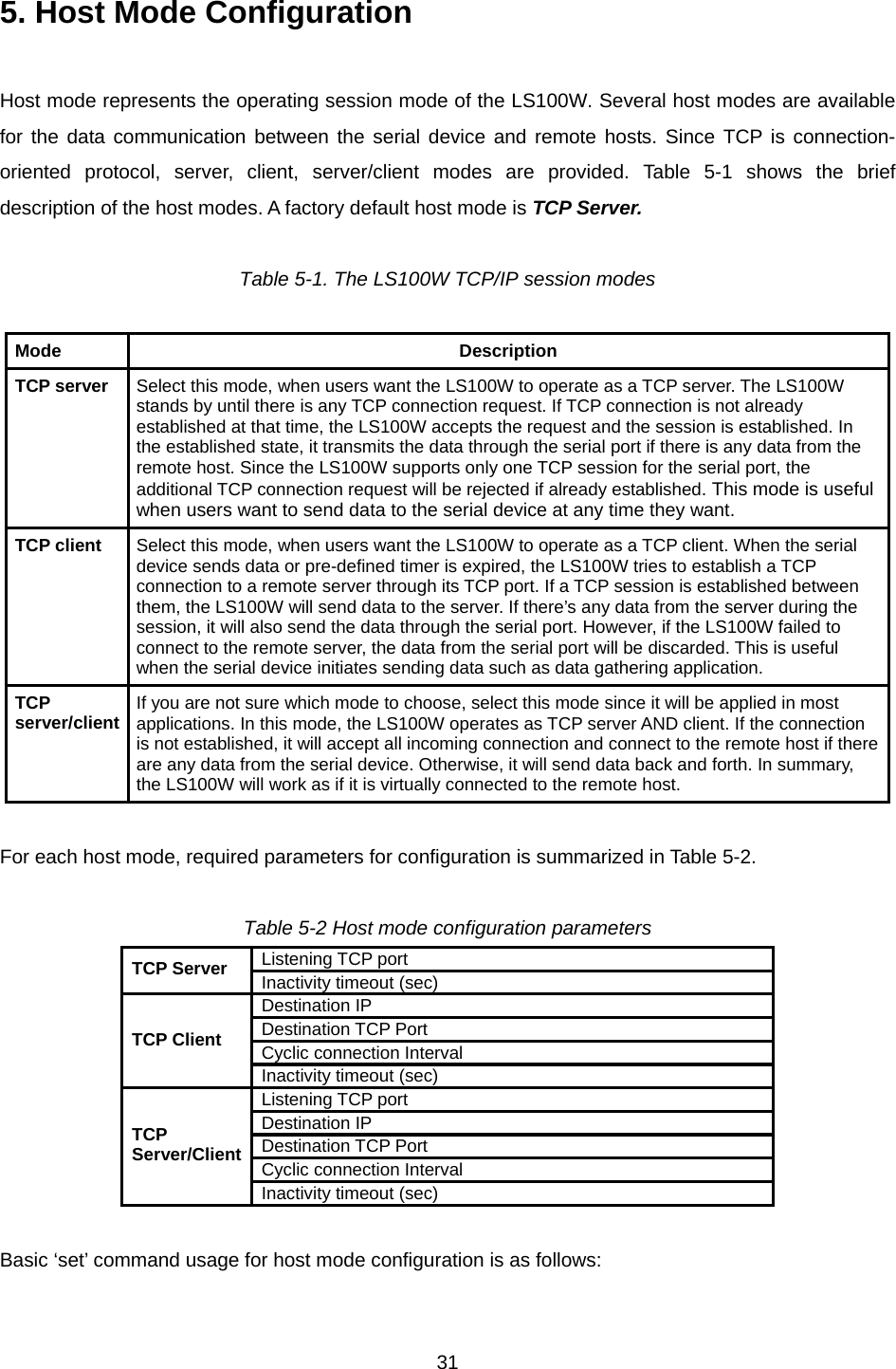
![32 set host hostmode par1 par2 ... where, hostmode: tcps=TCP server / tcpc=TCP client / tcpsc=TCP server & client parameters: if hostmode = TCP server (tcps), par1 = listening TCP port, par2 = inactivity timeout (sec) if hostmode = TCP client (tcpc), par1 = destination IP address, par2 = destination TCP port, par3 = cyclic connection interval (min), par4 = inactivity timeout (sec) if hostmode = TCP server & client (tcpsc), par1 = listening TCP_port, par2 = destination IP address, par3 = destination TCP port, par4 = cyclic connection interval (min), par5 = inactivity timeout (sec) * set cyclic connection interval to 0 not to use cyclic connection * set inactivity timeout to 0 for unlimited timeout For easier understanding of TCP modes, a simplified State Transition Diagram is often used. And too help users understand the diagram, the TCP state of the LS100W is briefly described as follows. - Listen It represents “a waiting for a connection request from any remote host”. It is a default start-up mode when it is set as TCP server mode. This state is valid only in TCP server mode operation. - Closed It means “No connection state at all”. If the data transfer is completed, the state is changed to this state if one of the host requests disconnection request. If it is in TCP server mode, the state is automatically changed to [Listen] mode. It is a default start-up mode when it is set as TCP client mode or TCP server/client mode. - Sync-Received In TCP server mode, the state will be changed from [Listen] to [Sync-Received], if any remote host sends connection request. If the LS100W accepts the request, the state will be changed into [Established]. This state is not valid in TCP client mode.](https://usermanual.wiki/Sena-Technologies/LS100W/User-Guide-572937-Page-32.png)
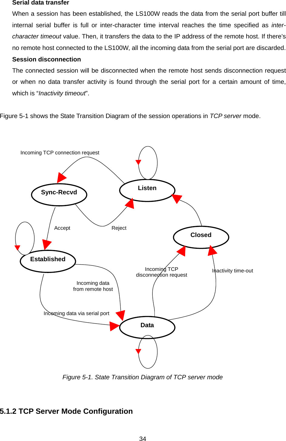
![33- Sync-Sent If the LS100W sends a connection request to a remote host, the state is changed from [Closed] to [Sync-Sent]. This state is maintained until the remote host accepts the connection request. This state is valid only in TCP client mode. - Established It represents “an open connection”. If one of the hosts accepts a connection request from the other host, the connection is opened and state is changed into [Established]. - Data When it is in [Established] state, data from a host will be transferred to the other one. For easier understanding of the TCP session operation, we called the state as [Data] state when actual data transfer is performed. Actually, the [Data] mode is a part of [Established] state as is described in the RFC 793 [Transmission Control Protocol]. This is a normal state for the data transfer phase of the connection. 5.1 TCP Server Mode Operations 5.1.1 Overview The LS100W works as a TCP server, and the default TCP state is [Listen] in this mode. The LS100W supports only one TCP socket connection per one serial port. If a connection is currently established, the additional connection requests will be rejected. The remote host will be either Ethernet-Serial communication devices acting as a TCP client or a socket program acting as a TCP client running on users’ PC. 1) Typical State Transition [Listen] --> [Sync-Received] --> [Established] --> [Data] --> [Closed] --> [Listen] At start-up, an initial TCP state is [Listen]. If there is any incoming TCP connection request, the state will be changed into [Sync-Received], then [Established], which means a session is opened. For a while, data will be transferred between the hosts. This is the [Data] state. The session will be disconnected due to the request of one of them, which is [Closed] state. And then, the state is automatically changed to its original state, [Listen]. 2) Operations](https://usermanual.wiki/Sena-Technologies/LS100W/User-Guide-572937-Page-33.png)
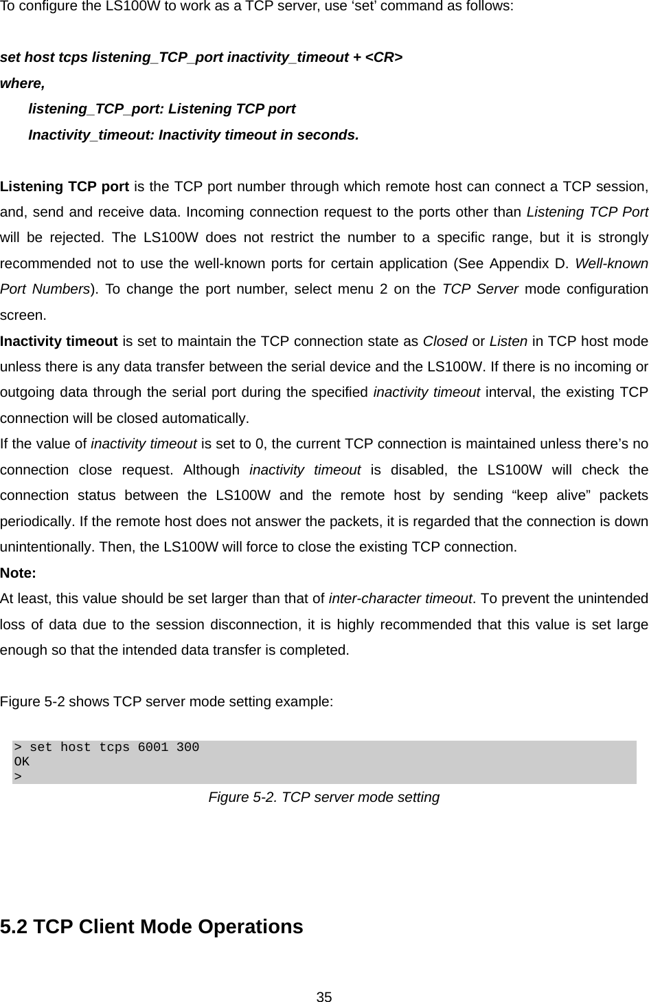
![365.2.1 Overview The LS100W works as a TCP client, and the default TCP state is [Closed] in this mode. The remote host will be either Ethernet-Serial communication devices acting as a TCP server or a socket program acting as a TCP server running on users’ PC. 1) Typical State Transition [Closed] --> [Sync-Sent] --> [Established] --> [Data] --> [Closed] At start-up, an initial TCP state is [Closed]. If there is any incoming data through the serial port, the LS100W will try to connect to a user-defined remote host. Then, the state will be changed to [Sync-Sent], which means the connection request is being sent. If the remote host accepts the request, the state will be changed into [Established], which means a session has been opened. For a while, data will be transferred between the hosts. This is [Data] state. The session will be disconnected due to the request of one of them, which is its original state, [Closed]. 2) Operations Serial data transfer Whenever the serial device sends data through the serial port of the LS100W, data will be accumulated to the serial port buffer of the LS100W. If the internal serial port buffer is full or inter-character time interval reaches to the time specified as inter-character timeout value, it tries to connect to the user-defined IP address of the remote host, if TCP session is not established yet. If the LS100W succeeds in connecting to the remote host, the data in the serial port buffer will be transferred to the host. Otherwise, all the data stored in the buffer will be cleared. Session disconnection The connected session will be disconnected when the remote host sends disconnection request or when no data transfer activity is found through the serial port for certain amount of time, which is “Inactivity timeout”. All the data remained in the serial port buffer will be cleared when it is disconnected. Connection request from remote host All the incoming TCP connection requests will be rejected in TCP client mode. Cyclic Connection It Cyclic Connection function is enabled, the LS100W will make an attempt to connect to the user-defined remote host at certain interval even if there’s no incoming serial data from the device. If the remote host prepares certain data, it will be transferred to the serial device via its serial port after the connection is established. Eventually, users can monitor the serial device periodically by making the remote host send the serial command to the LS100W whenever it is connected to the](https://usermanual.wiki/Sena-Technologies/LS100W/User-Guide-572937-Page-36.png)
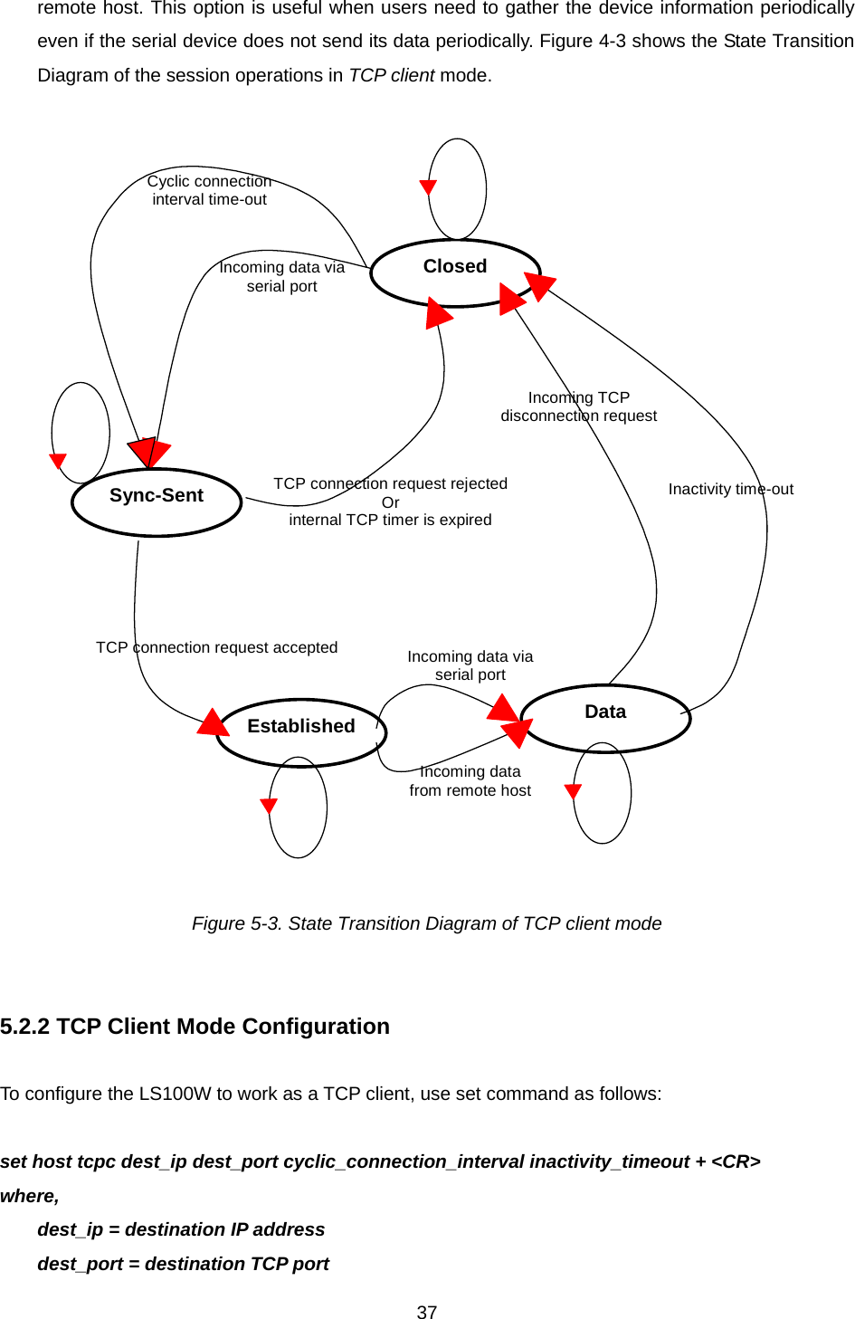
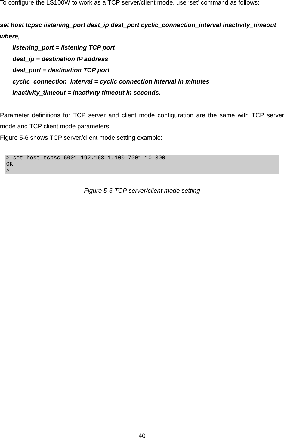
![38 cyclic_connection_interval = cyclic connection interval in minutes inactivity_timeout = inactivity timeout in seconds. Destination IP address and destination TCP Port are the information on the remote host to which the LS100W will try to connect in TCP client mode. The IP address (or domain name) should be specified together with the TCP port number. Cyclic connection interval is the time interval at which the LS100W will try to connect to the remote host regardless of the existence of incoming data from the serial port. If the interval is specified with a valid value other than 0, the function is enabled. The time interval will be the specified value by the unit of minute. If the interval is entered as 0, cyclic connection feature will be disabled. Inactivity timeout is the same as described in TCP server mode setting section. Figure 5-4 shows TCP client mode setting example: > set host tcpc 192.168.1.1 6001 10 300 OK > Figure 5-4 TCP client mode setting 5.3 TCP Server/Client Mode Operations 5.3.1 Overview The LS100W works as either TCP server or client according to the situation. This will be the typical mode for most applications, since it will transfer the data either from serial port or from TCP port. The default TCP state is [Listen] which is the same as that of TCP server mode. 1) Typical State Transition [Listen] --> [Sync-Received] --> [Established] --> [Data] --> [Closed] --> [Listen] Or [Listen] --> [Sync-Sent] --> [Established] --> [Data] --> [Closed] --> [Listen]](https://usermanual.wiki/Sena-Technologies/LS100W/User-Guide-572937-Page-38.png)
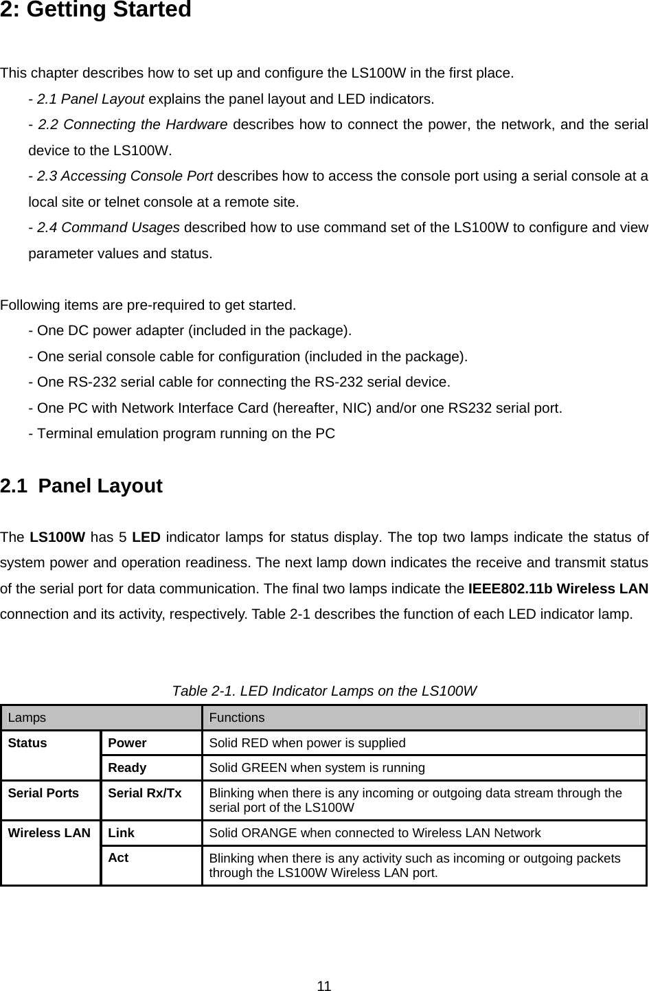
![39The initial state is [Listen]. If there are data coming from the serial port, it will connect to the remote host as a TCP client. If there is incoming connection request from the remote host, it will accept the connection as a TCP server, and then transfer data through the serial port. Thus, users can assume that the LS100W is always connected to the specified remote host. 2) Operations The only difference from TCP server mode is that the LS100W will try to connect and send serial data to the remote host even if the TCP session is not established. The difference from TCP client mode is that it will accept incoming connection request from remote host if the session is not established. The detailed operation principles are the same as that of TCP server and TCP client mode. Established Inactivity time-out TCP connection request rejected Or internal TCP time-out TCP connection request acceptedSync-SentIncoming data via serial portIncoming data from remote host In-coming TCP Close request Listen Incoming TCP connection requestIncoming data via serial portSync-RecvdReject Accept Closed Data Figure 5-5. State Transition Diagram of TCP server/client mode 5.3.2 TCP Server/Client Mode Configuration](https://usermanual.wiki/Sena-Technologies/LS100W/User-Guide-572937-Page-39.png)