Sena Technologies PARANIMSP100 Bluetooth IP Gateway User Manual users manual
Sena Technologies,Inc. Bluetooth IP Gateway users manual
UserManual.wiki
>
Sena Technologies
>
PARANIMSP100 User Manual
users manual
Navigation menu
Upload a User Manual
Namespaces
Wiki Guide
HTML
PDF
Info
Views
User Manual
Discussion / Help
Navigation
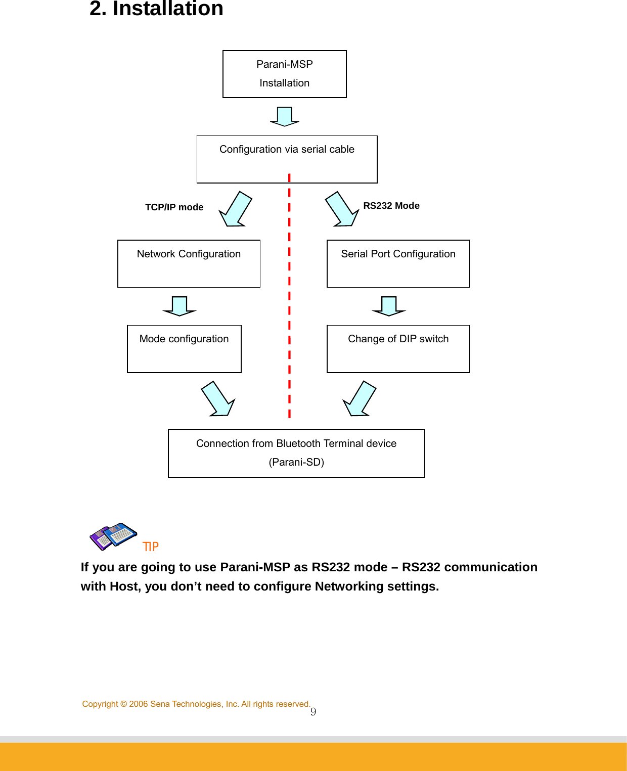
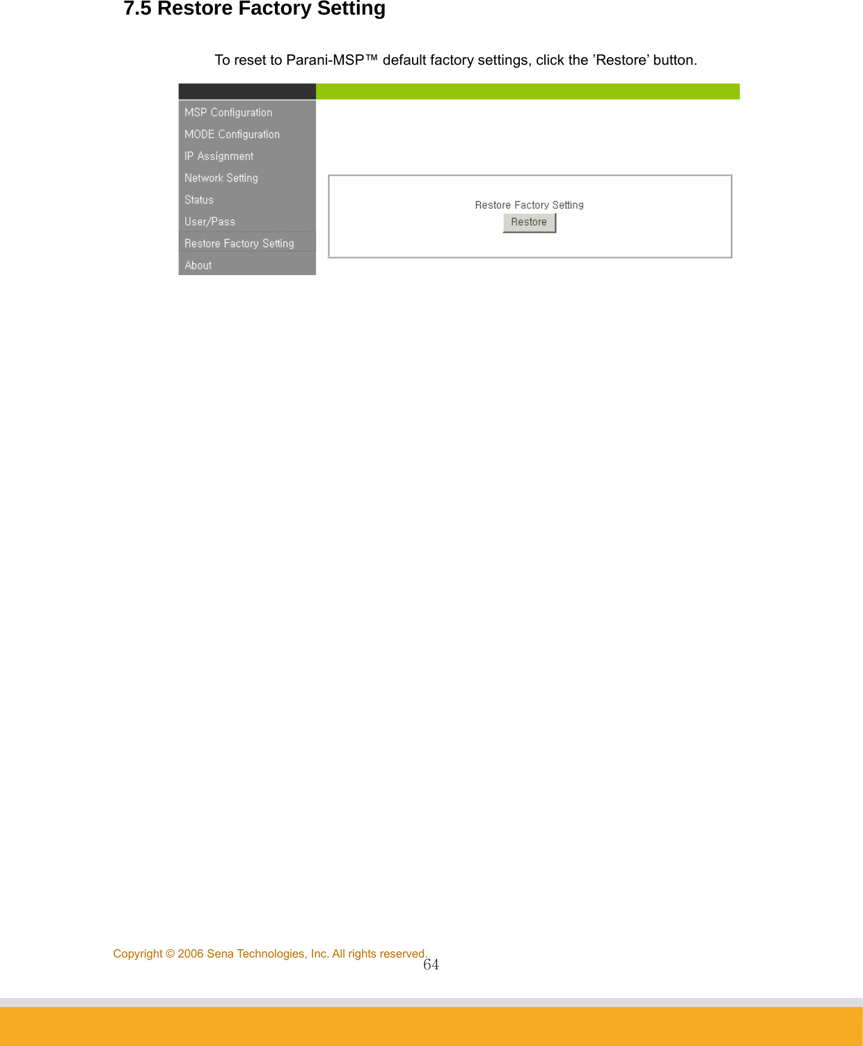
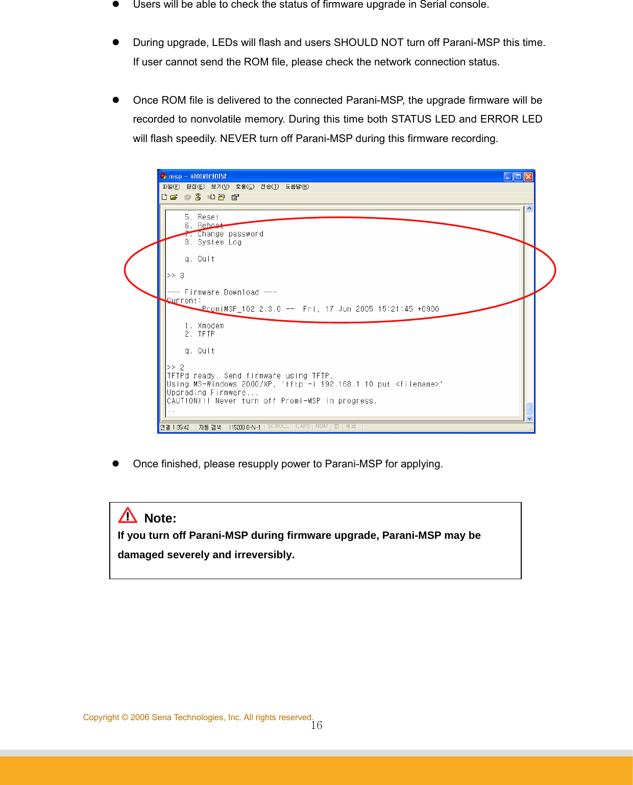
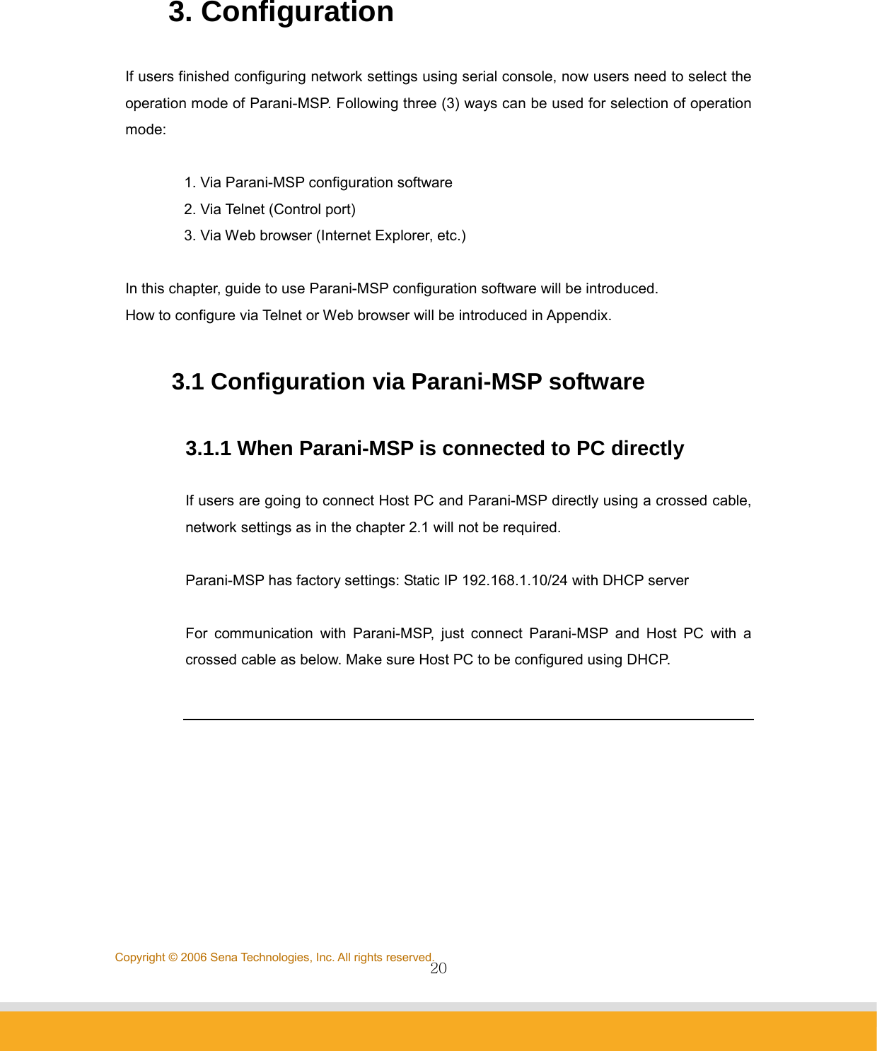
![12Copyright © 2006 Sena Technologies, Inc. All rights reserved.(11) Please enter your Netmask/Gateway/DNS information, as in below for example: (12) Press Enter; Parani-MSP™ will prompt reboot request. Enter ‘Y’ [Yes]; press Enter to reboot Parani-MSP™ to apply the revised Network Settings. (13) Enter Login ID and Password. Default ID: admin, Password: 11111 (14) Revised Network settings are displayed <An example: Revised Network Settings> (15) Networking configuration is complete. The preceding example shows static IP assignment to Parani-MSP™. User selects static, DHCP or PPPoE IP as needed.](https://usermanual.wiki/Sena-Technologies/PARANIMSP100/User-Guide-707563-Page-12.png)
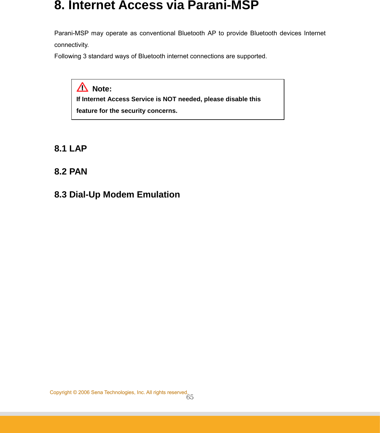
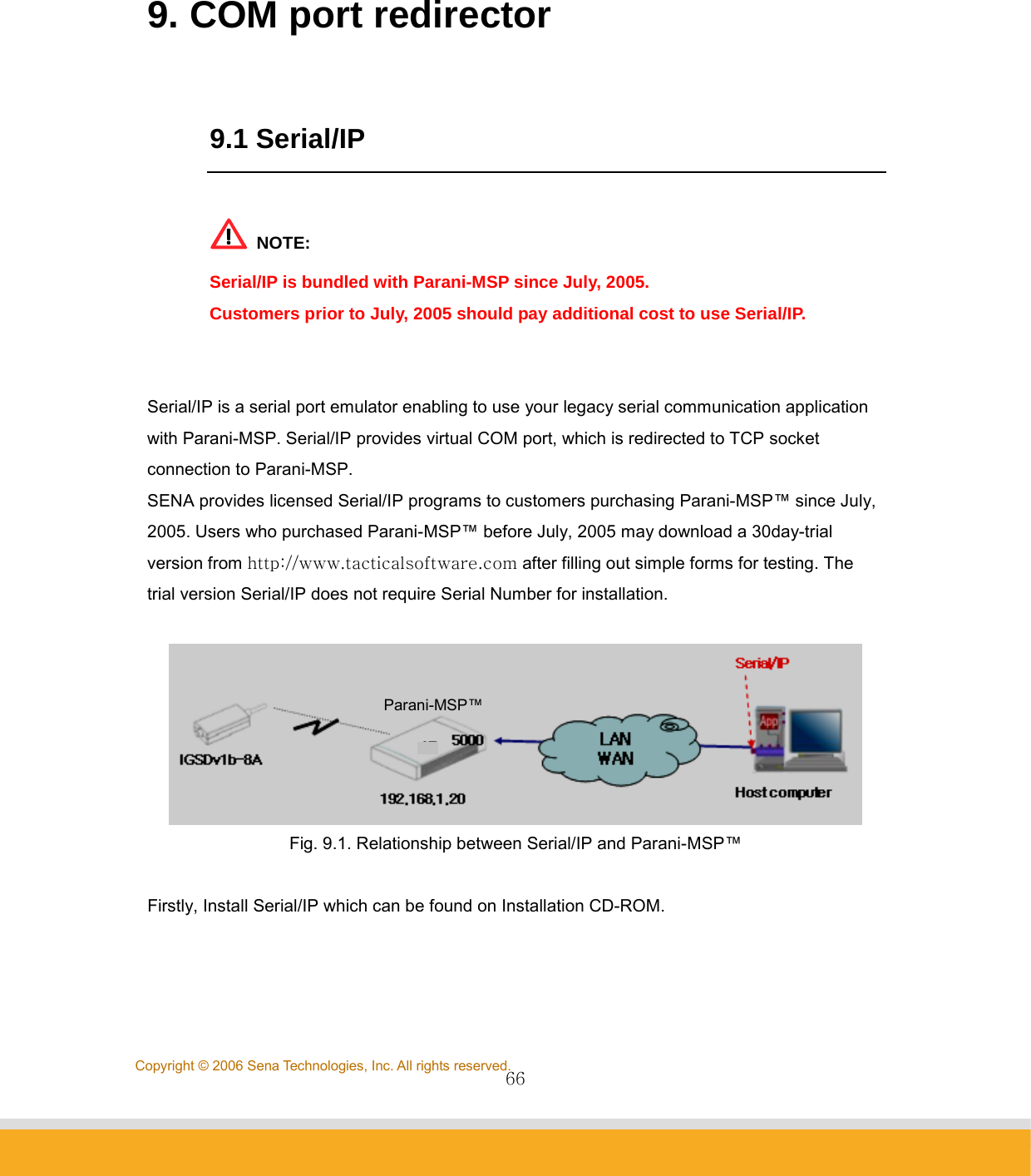
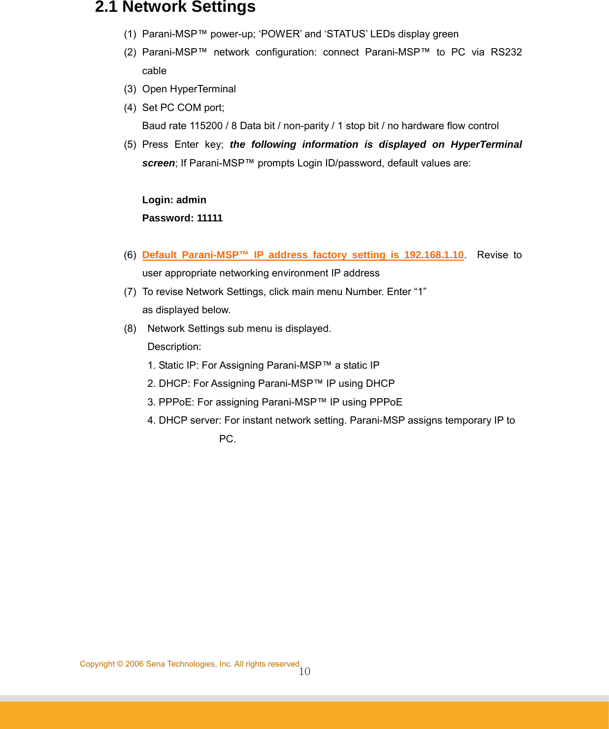
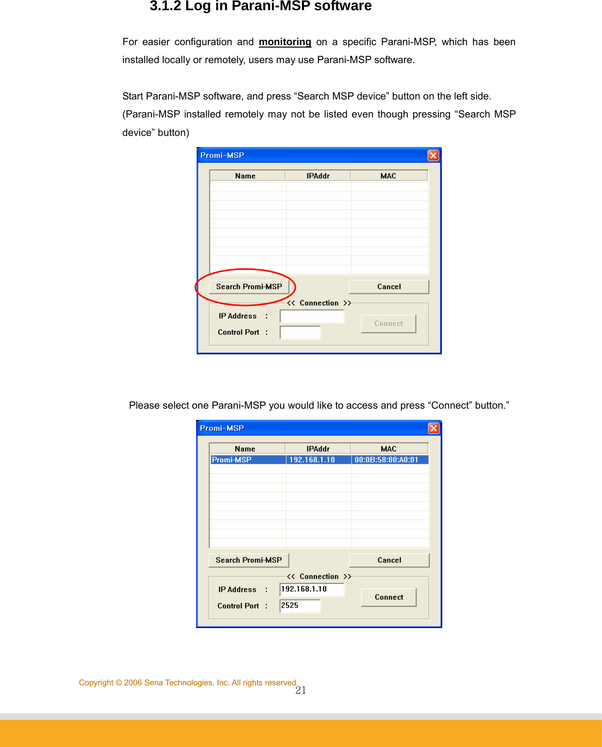
![13Copyright © 2006 Sena Technologies, Inc. All rights reserved. 2.2 LAN Access Profile Parani-MSP™ supports LAN Access Profile for Bluetooth networking Access Point. By direct connection of Parani-MSP™ to ADSL, the internet is accessible via Bluetooth. Select menu 2. LAP by entering ‘2’; Parani-MSP™ prompts for LAP profile enable/disable. Select ‘Y’ [Yes] to enable or ‘N’ [No] to disable LAP profile. TIP: For Internet connection, both LAP and NAP devices may access to the internet. For more information, please refer to chapter 8.](https://usermanual.wiki/Sena-Technologies/PARANIMSP100/User-Guide-707563-Page-13.png)
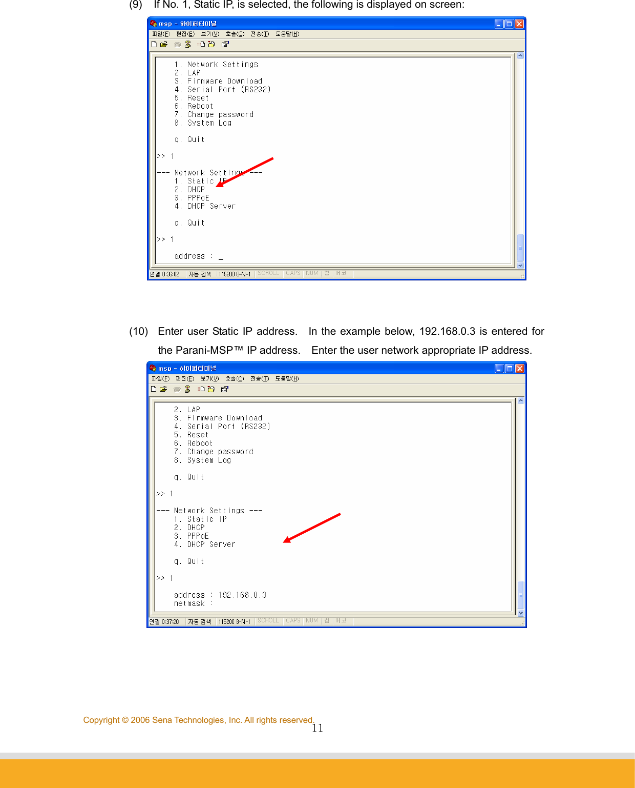
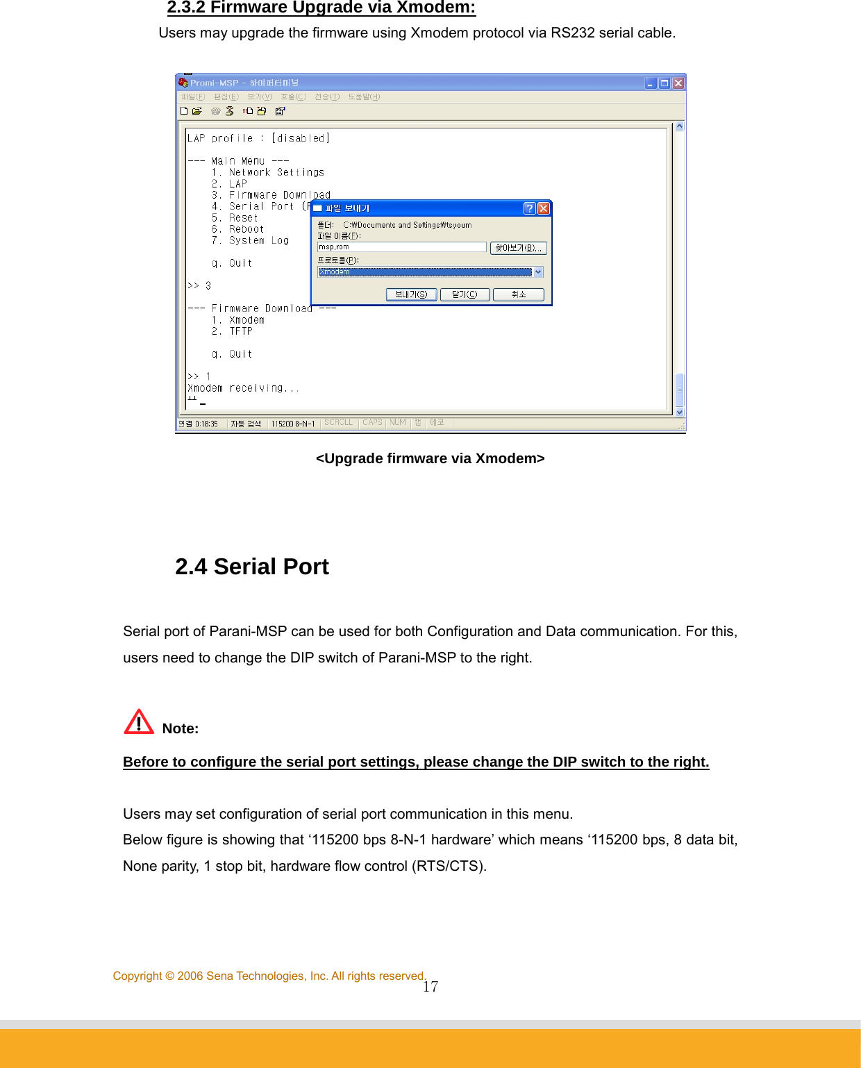
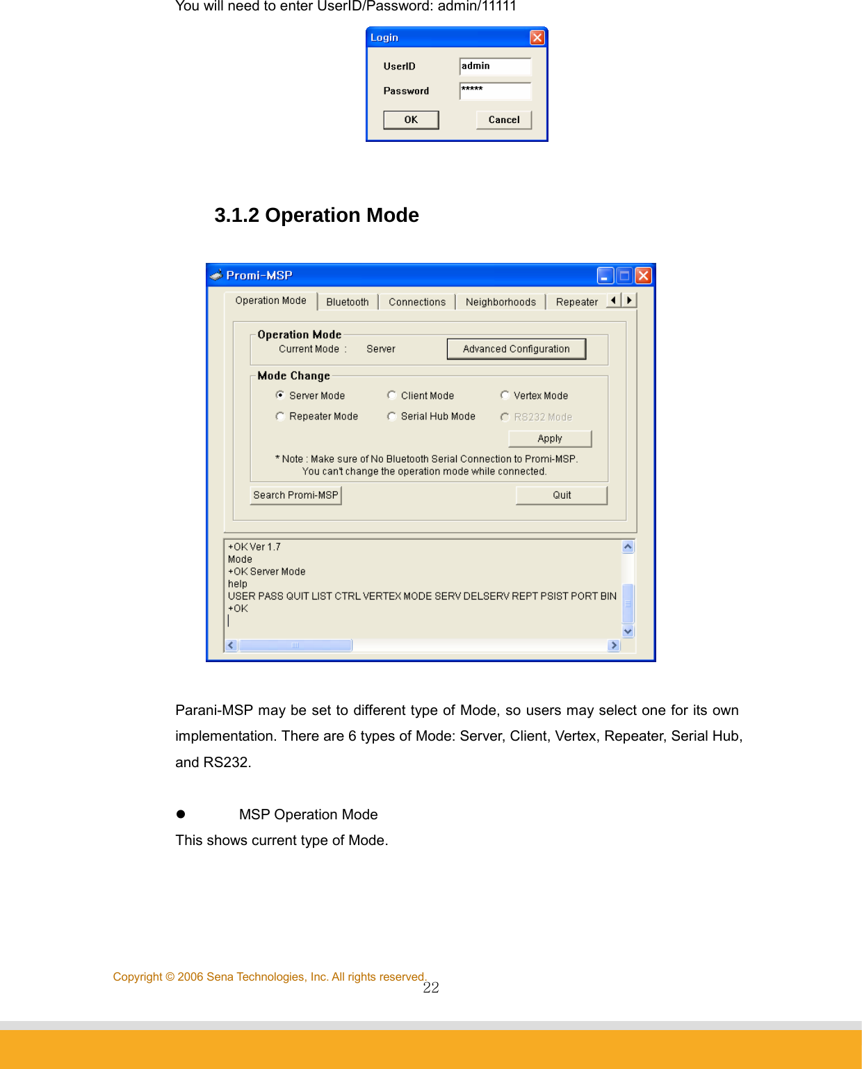
![15Copyright © 2006 Sena Technologies, Inc. All rights reserved.3. Firmware Download → 2.TFTP z Then you will get following screen: z Place the MSP upgrade ROM file which is downloaded from SENA web site to C:\ folder on your PC and run tftp command on [Start] →[Run] as below. z Users need to make sure that the upgrade ROM file is in the same location or users need to specify the exact location to send the ROM file to the connected Parani-MSP via crossed ethernet cable. z Below window is showing the procedure of sending ROM file named “msp2_040906.rom” to the connected Parani-MSP via TFTP.](https://usermanual.wiki/Sena-Technologies/PARANIMSP100/User-Guide-707563-Page-15.png)
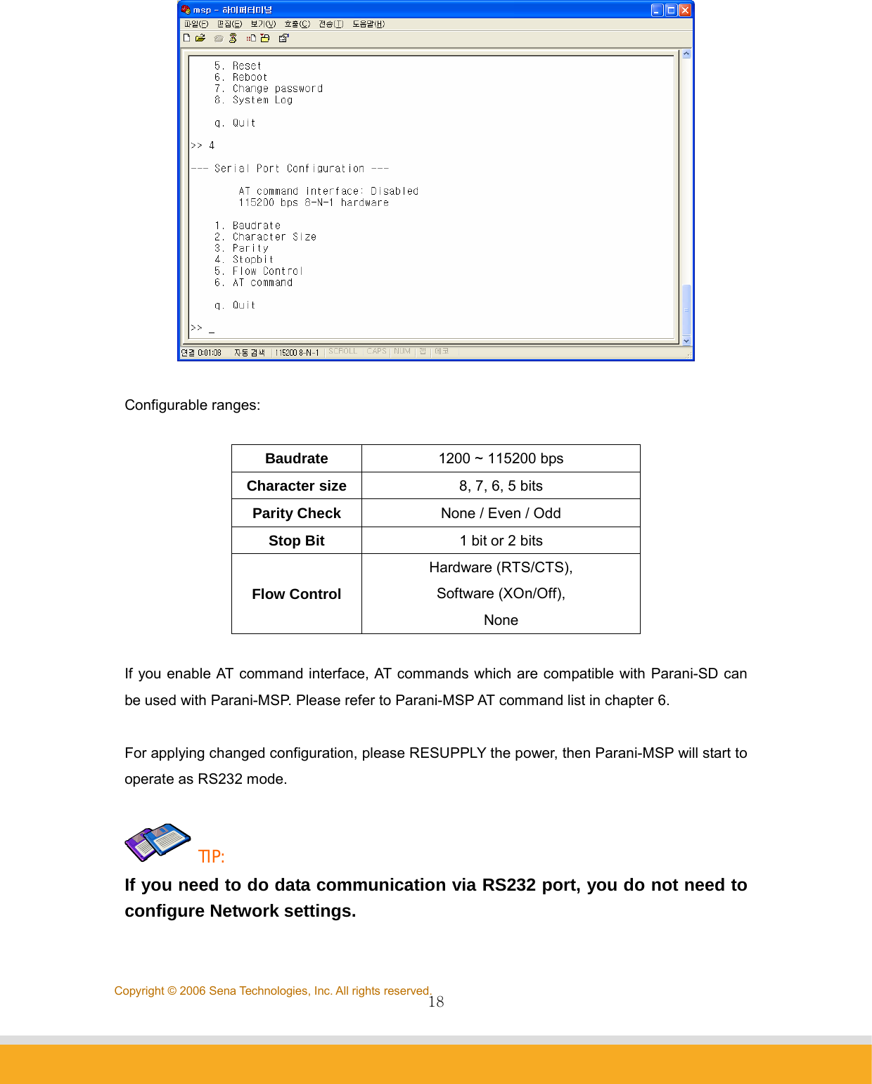
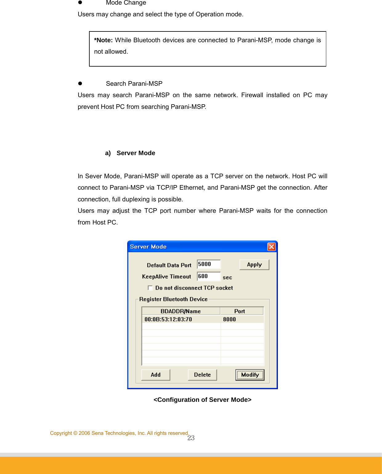
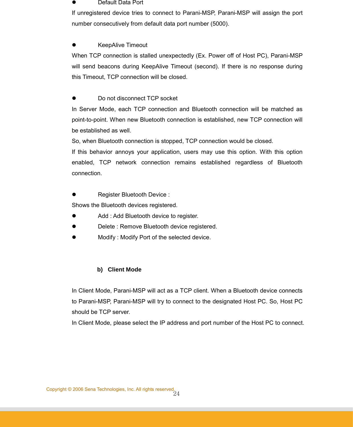
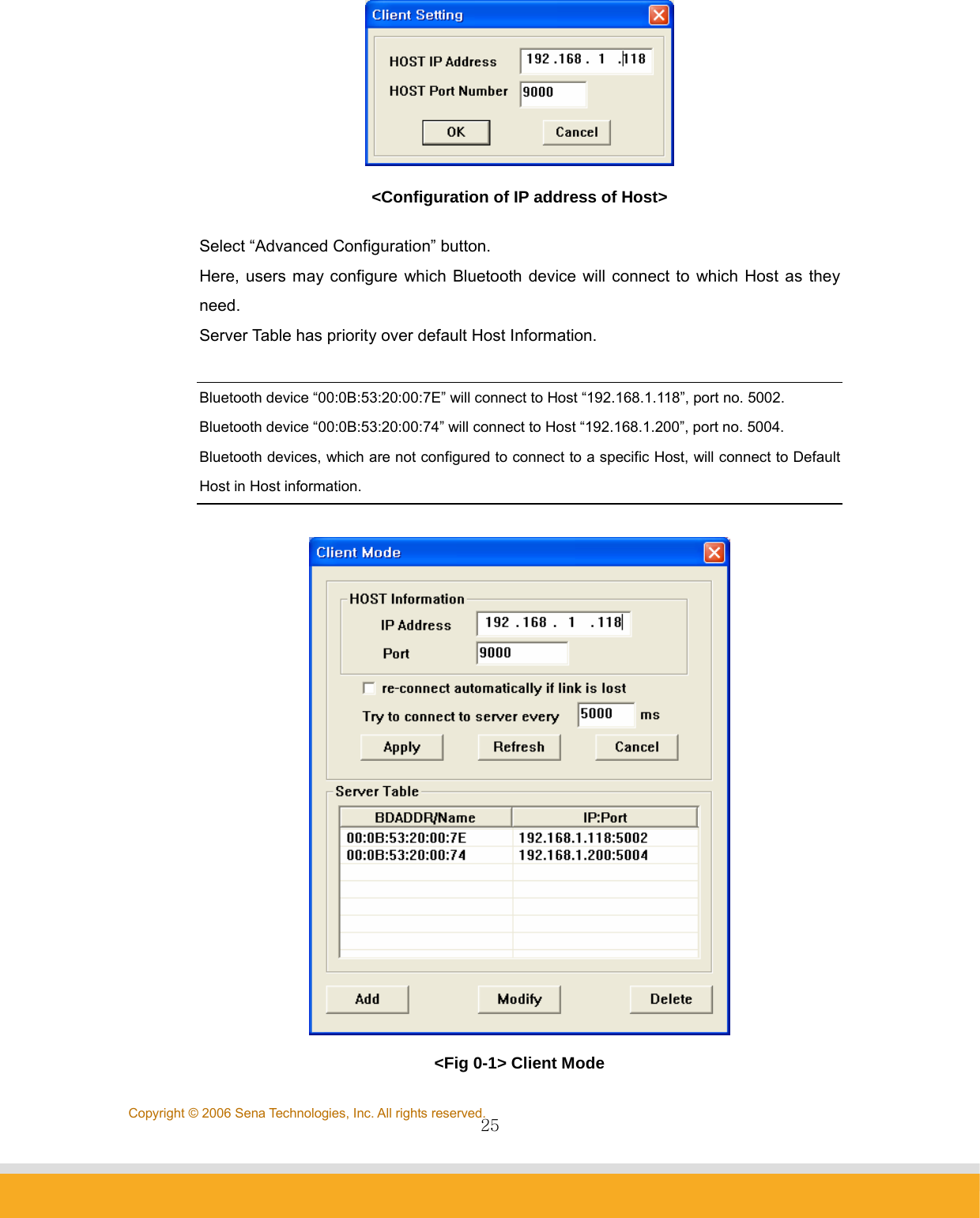
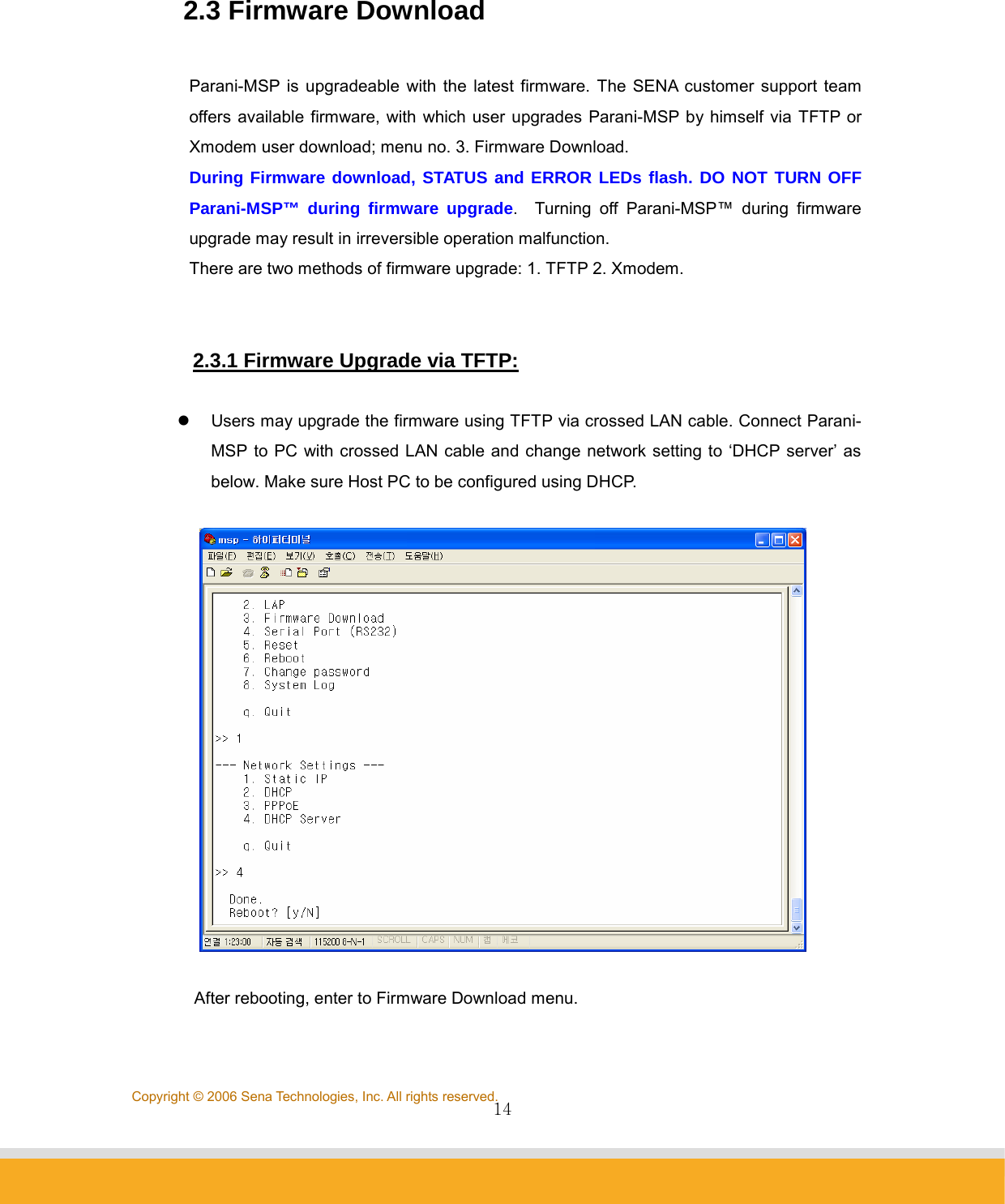
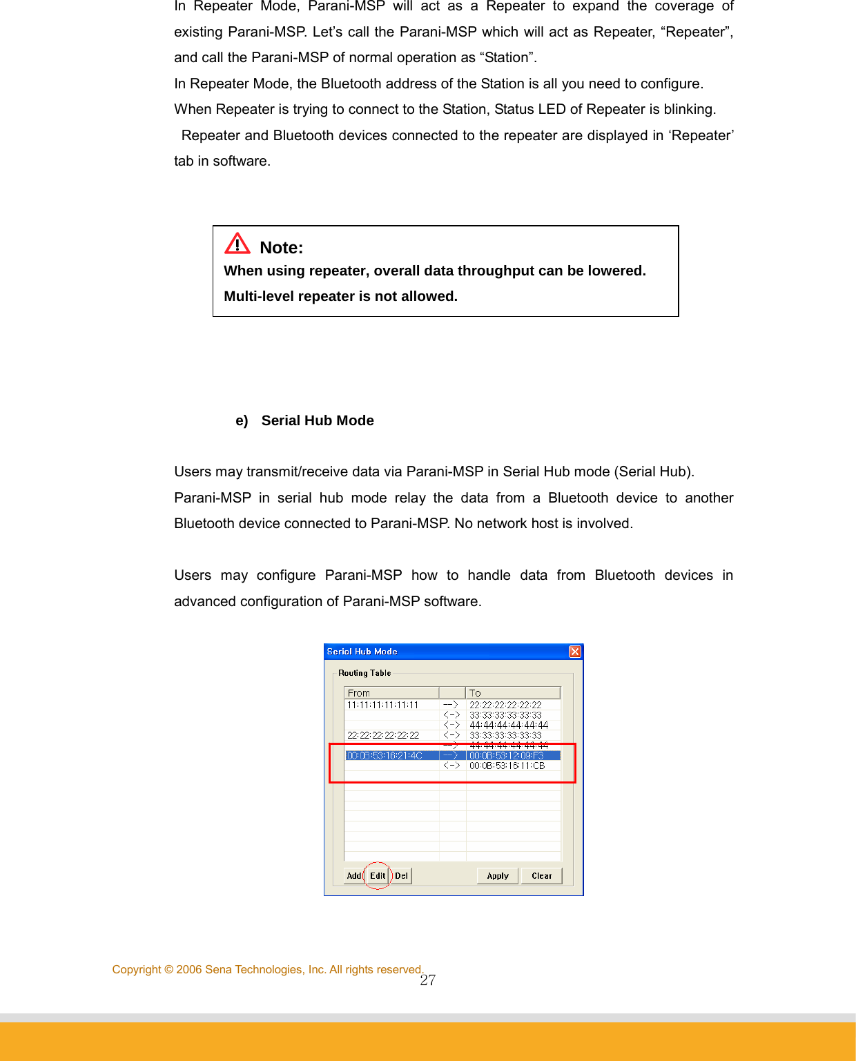
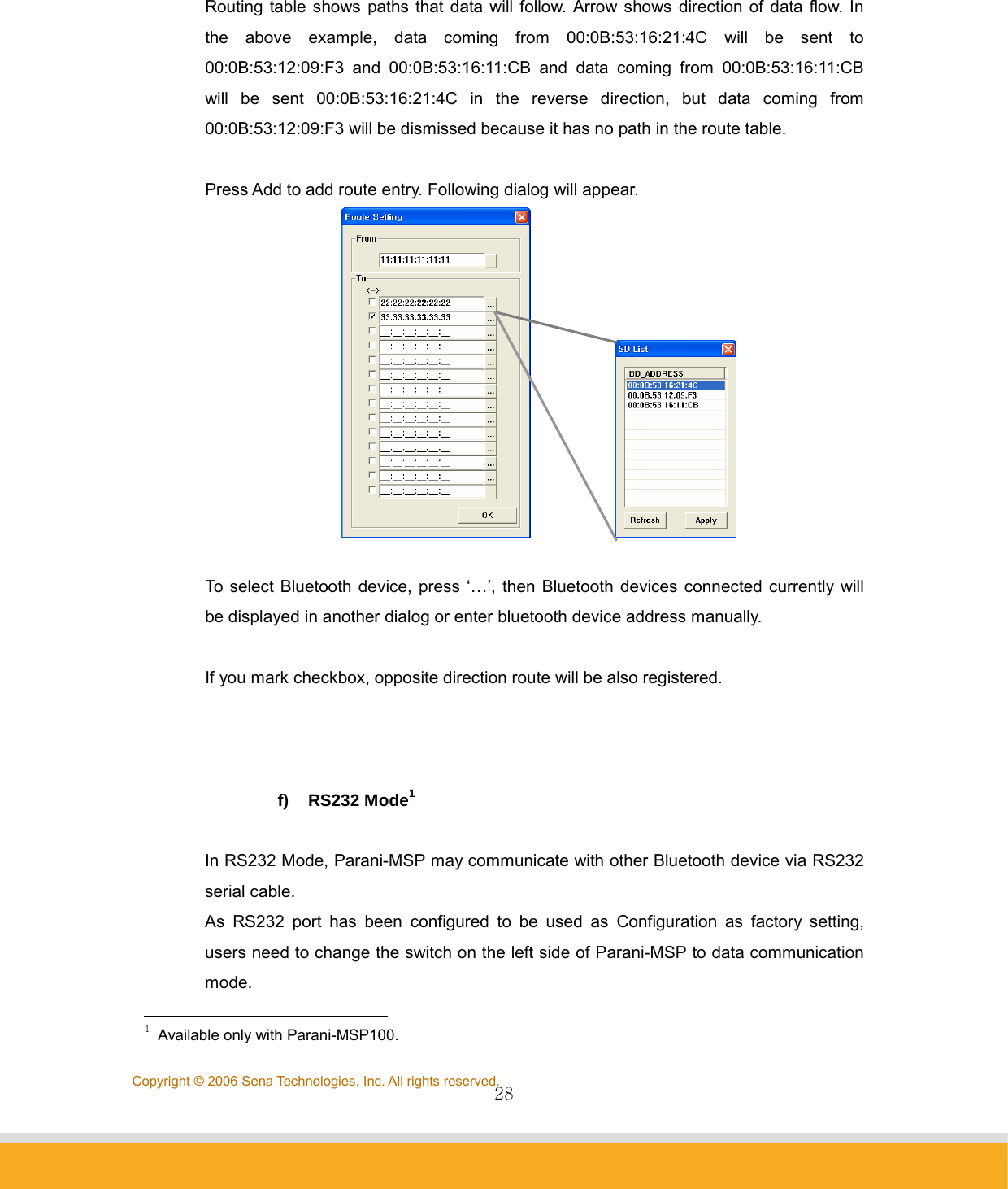
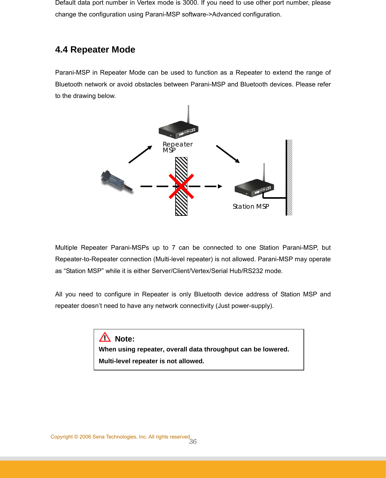
![26Copyright © 2006 Sena Technologies, Inc. All rights reserved. z Host IP Address For network Server IP address entry z Host Port Number For network port no. entry z re-connect automatically if link is lost. For Host connect retry, if failed. Retry frequency is set in the preceding function.. z Try to Connect to Server every [ ] ms When Parani-MSP™ fails to connect to Host, it will retry. Enter the connection retry frequency here. Entering 0 [zero] means no retry. c) Vertex Mode In Vertex Mode, Host and Bluetooth devices communicate each other via Parani-MSP™ in multi-drop manner, which is similar to RS485 way. Parani-MSP acts as TCP server like server mode. It waits for connection from Host on Vertex Port. <Fig 0-2> Vertex Mode z Vertex Port For Parani-MSP™ Vertex port no. entry. z Max Number of Connections For entering the number of Hosts connectable to Parani-MSP™ concurrently. d) Repeater Mode](https://usermanual.wiki/Sena-Technologies/PARANIMSP100/User-Guide-707563-Page-26.png)
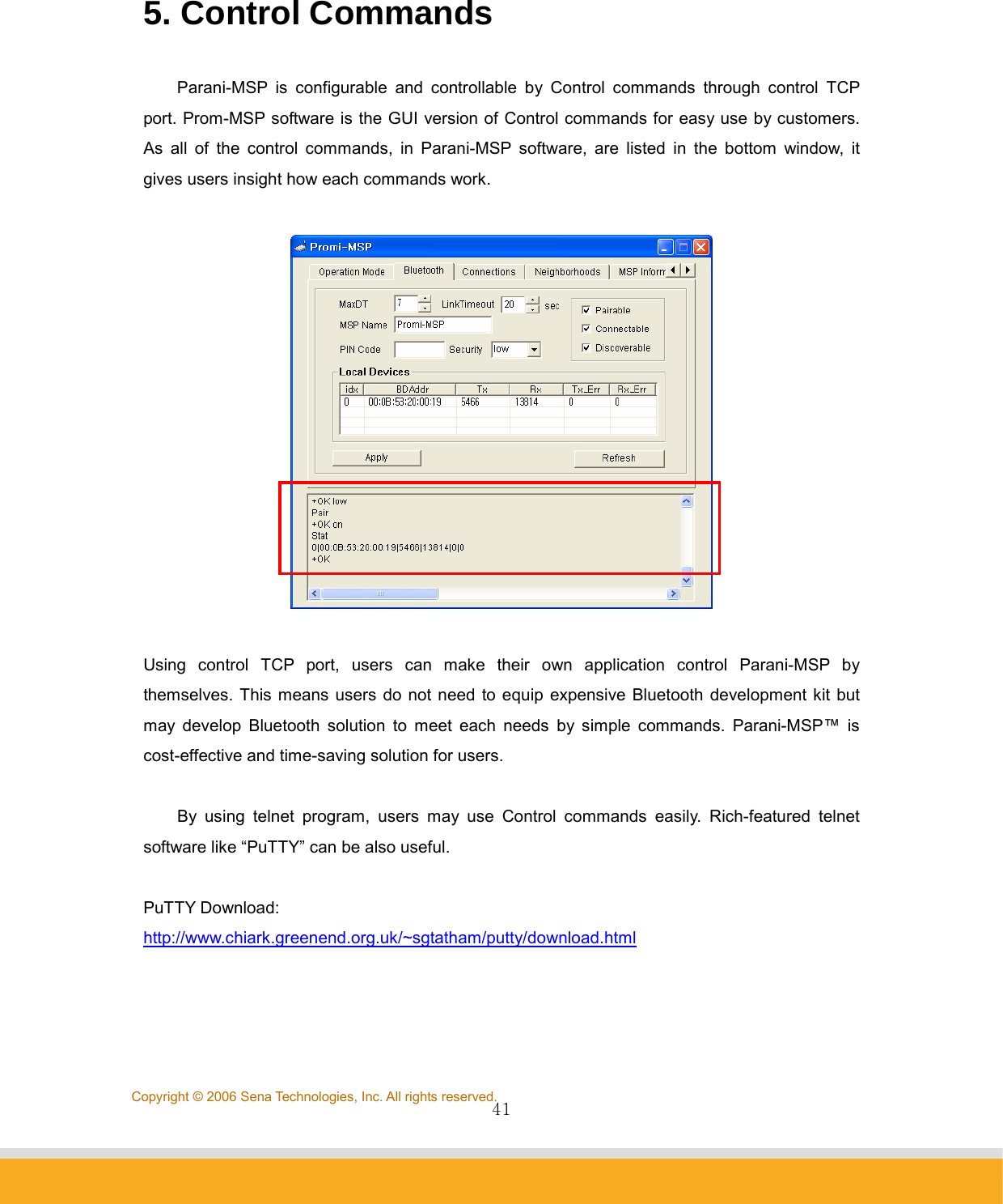
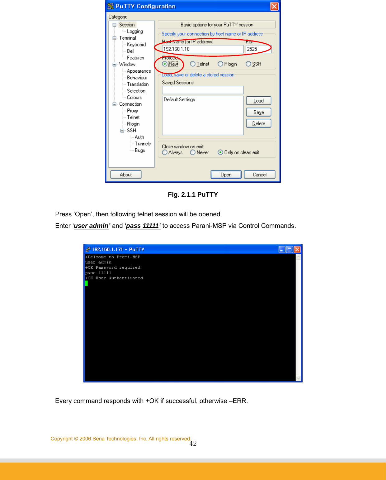
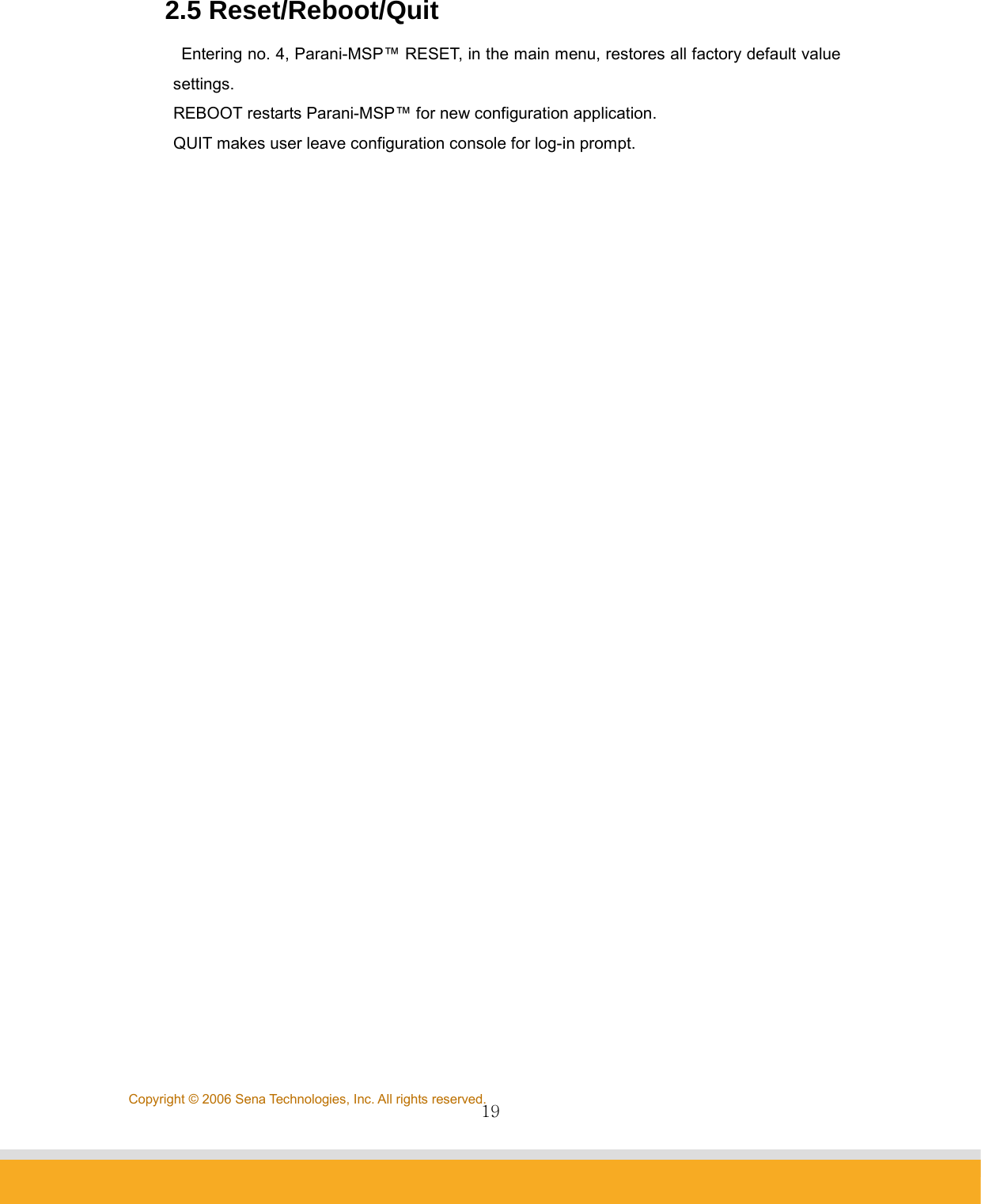
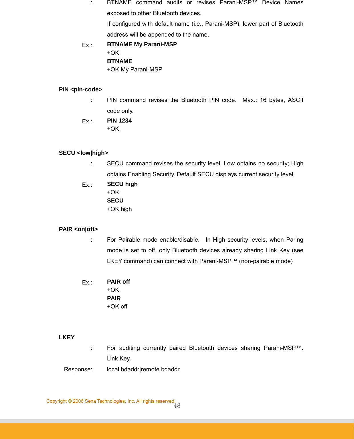
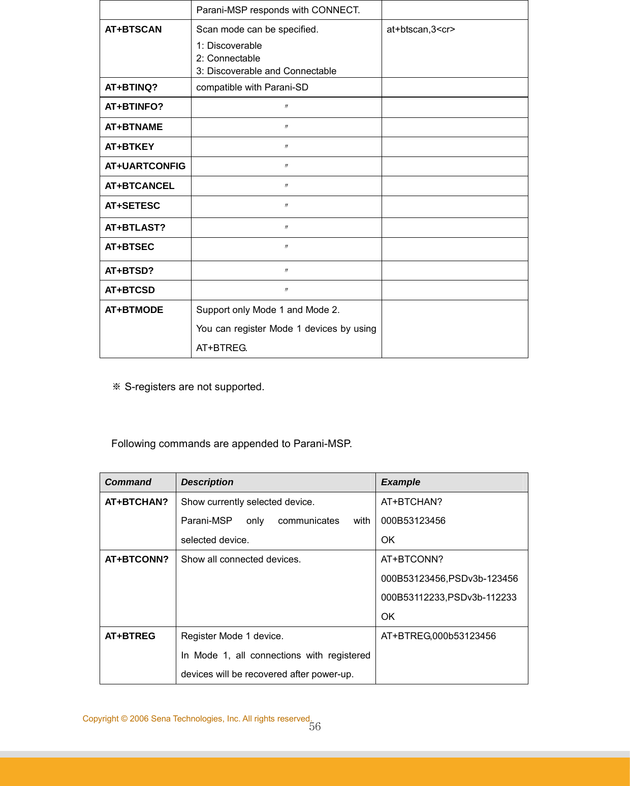
![43Copyright © 2006 Sena Technologies, Inc. All rights reserved.5.1 Basic Commands USER <username> : To enter Log in Name Ex.: USER admin +OK Password required PASS <password> [new password] : To enter or change the Password for logging in. Below Example shows how to change Password from ‘11111’ to ‘1234’ Ex: PASS 11111 +OK User Authenticated PASS 11111 1234 +OK QUIT : To quit the communication with Parani-MSP Ex.: QUIT +OK Disconnected MODE [server|client|vertex|hub|repeater|rs232] : To check or change the current Operation MODE of Parani-MSP. If any of Bluetooth devices are connected to Parani-MSP, MODE change is not allowed. Before changing the MODE, please drop all of Bluetooth connections first. Ex.: MODE +OK Server Mode MODE CLIENT +OK Client Mode 5.2 Commands for Server Mode PORT [port no.] : To configure default data port number of Server Mode Parani-MSP. If a Bluetooth device, which is not pre-registered to Parani-MSP, has](https://usermanual.wiki/Sena-Technologies/PARANIMSP100/User-Guide-707563-Page-43.png)
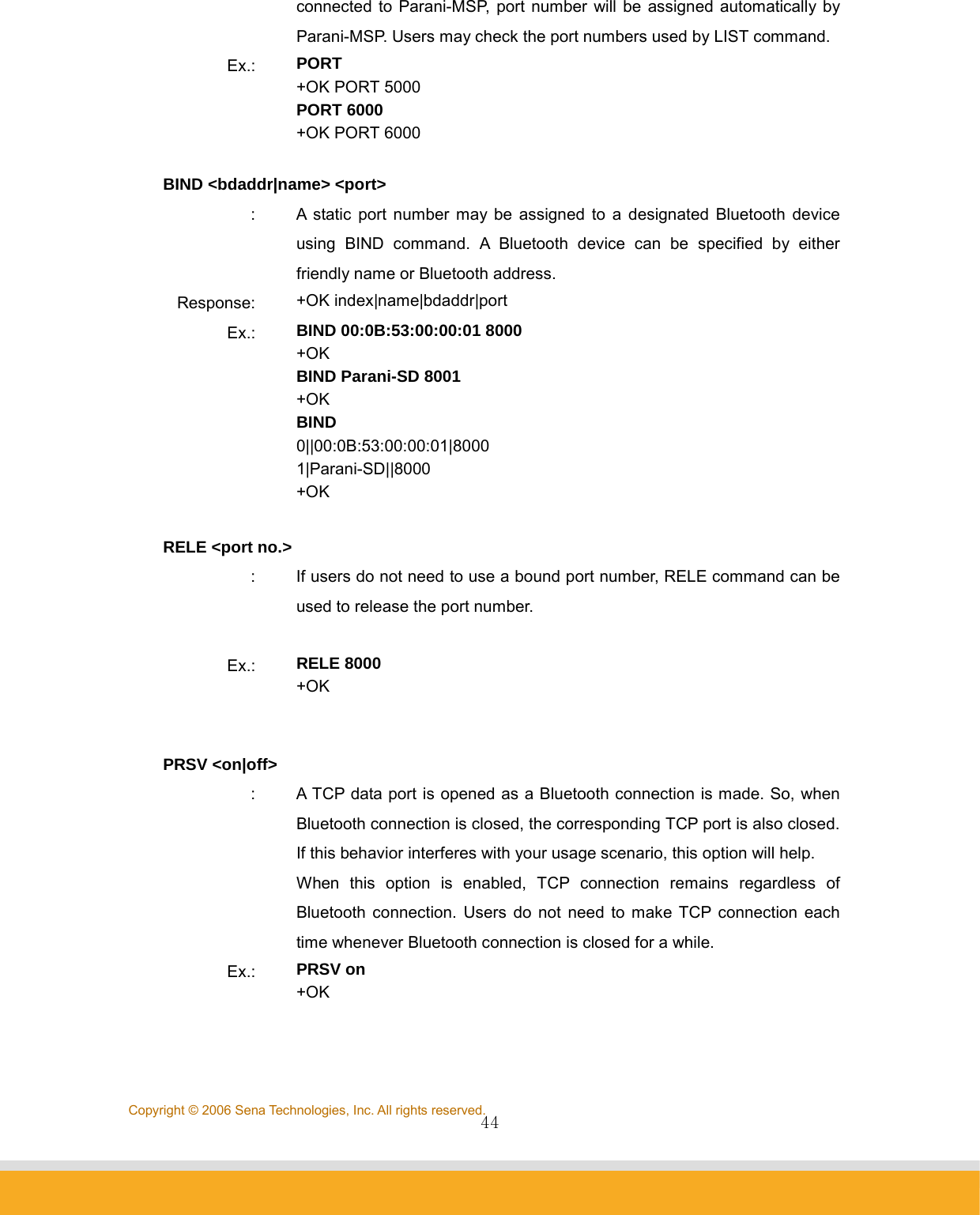
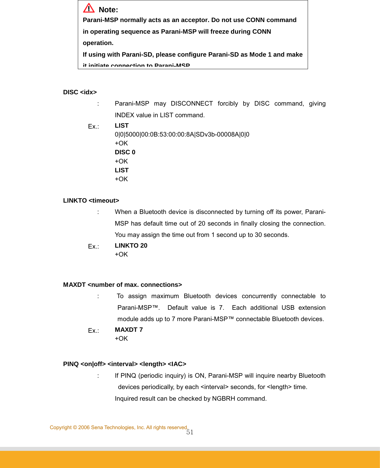
![45Copyright © 2006 Sena Technologies, Inc. All rights reserved. KATO <time> <probe> <interval> : To configure ‘TCP Keep Alive Time’ When Host, which is communicating with Parani-MSP via network, is stalled unintentionally, Parani-MSP cannot aware this unexpected disconnection. Accordingly, Parani-MSP sends beacon packets to monitor connection status when there is no data communication for certain time. When there is no data communication for <time>, Parani-MSP will send beacon packet <probe> times to monitor the connection, by each <interval>, before closing the connection. Below example means when there is no communication for 10 min., Parani-MSP will send beacon packets 3 times by 10 seconds interval. Ex.: KATO 600 3 10 +OK KATO 600 3 10 5.3 Commands for Client Mode SERV <IP Address:Port> [bdaddr|name] : To assign IP address and port number of server host where Parani-MSP will send connection request in client mode. If you enter either bluetooth address or friendly name of the Bluetooth device, you may configure different host addresses and port numbers for each Bluetooth devices. Response: index|name|bdaddr|server_IP:port Ex.: SERV 192.168.1.11:9000 +OK SERV 192.168.1.11:9001 Parani-SD +OK SERV 0|Parani-SD||192.168.1.11:9001 +OK 192.168.1.11:9000 DELSERV <bdaddr|name> : To delete Host information stored by SERV command.](https://usermanual.wiki/Sena-Technologies/PARANIMSP100/User-Guide-707563-Page-45.png)
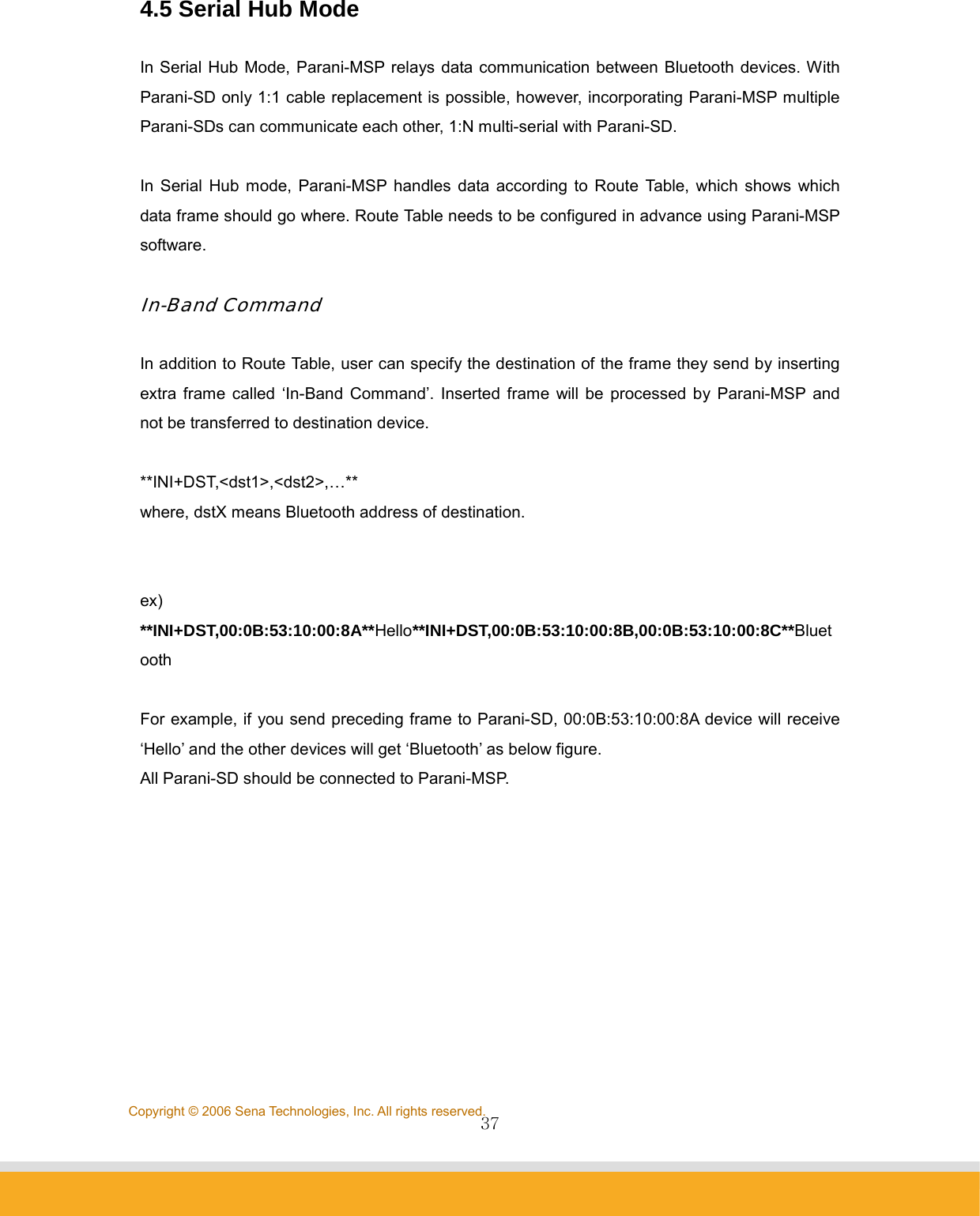
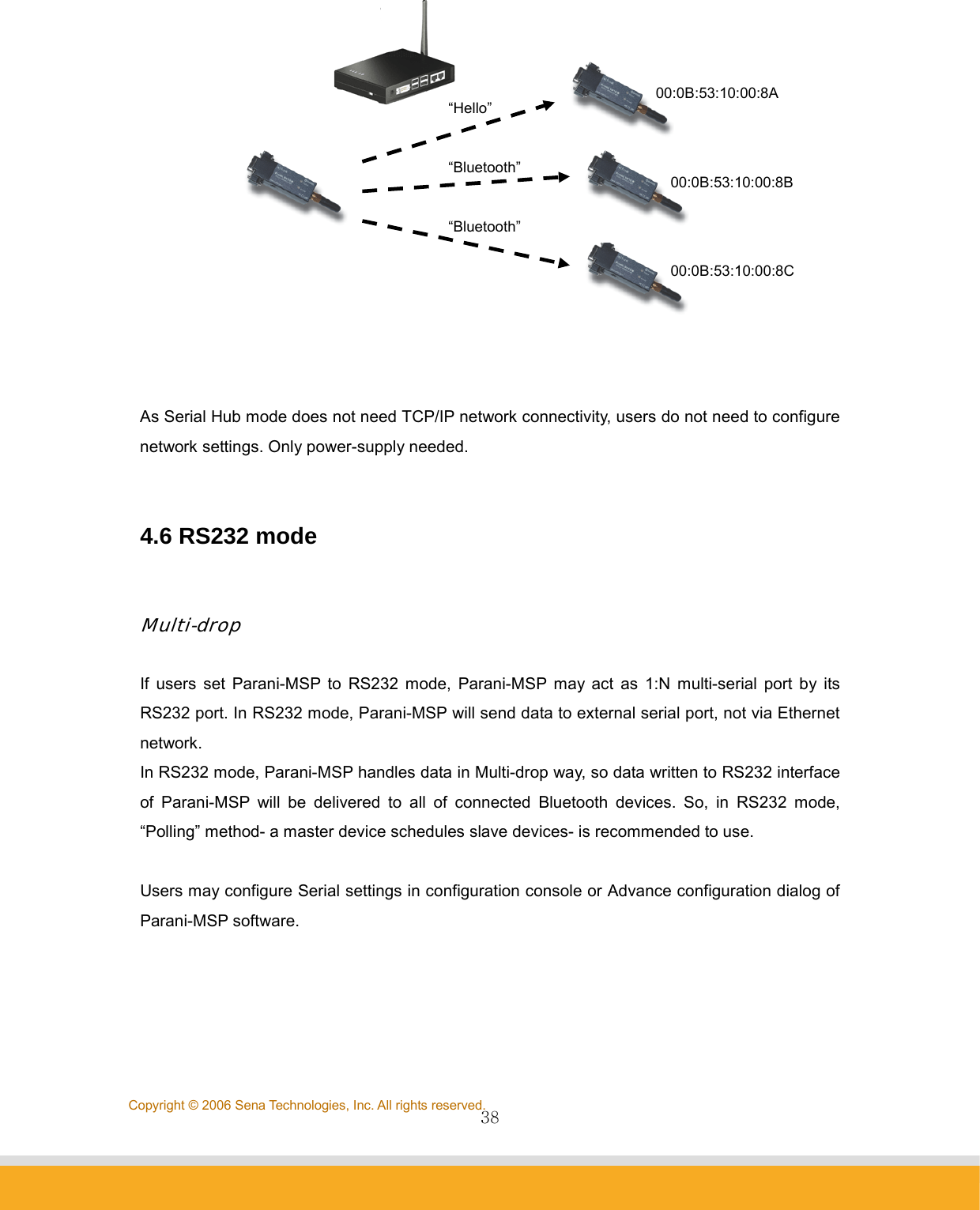
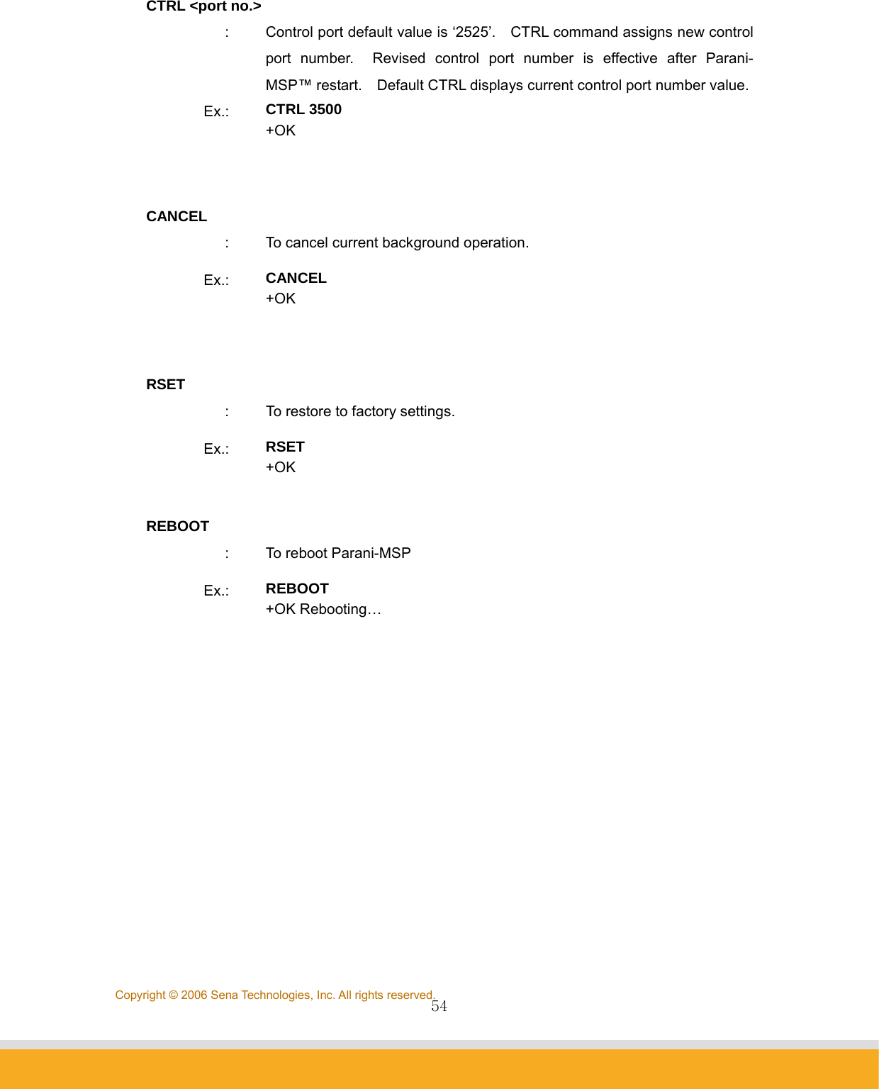
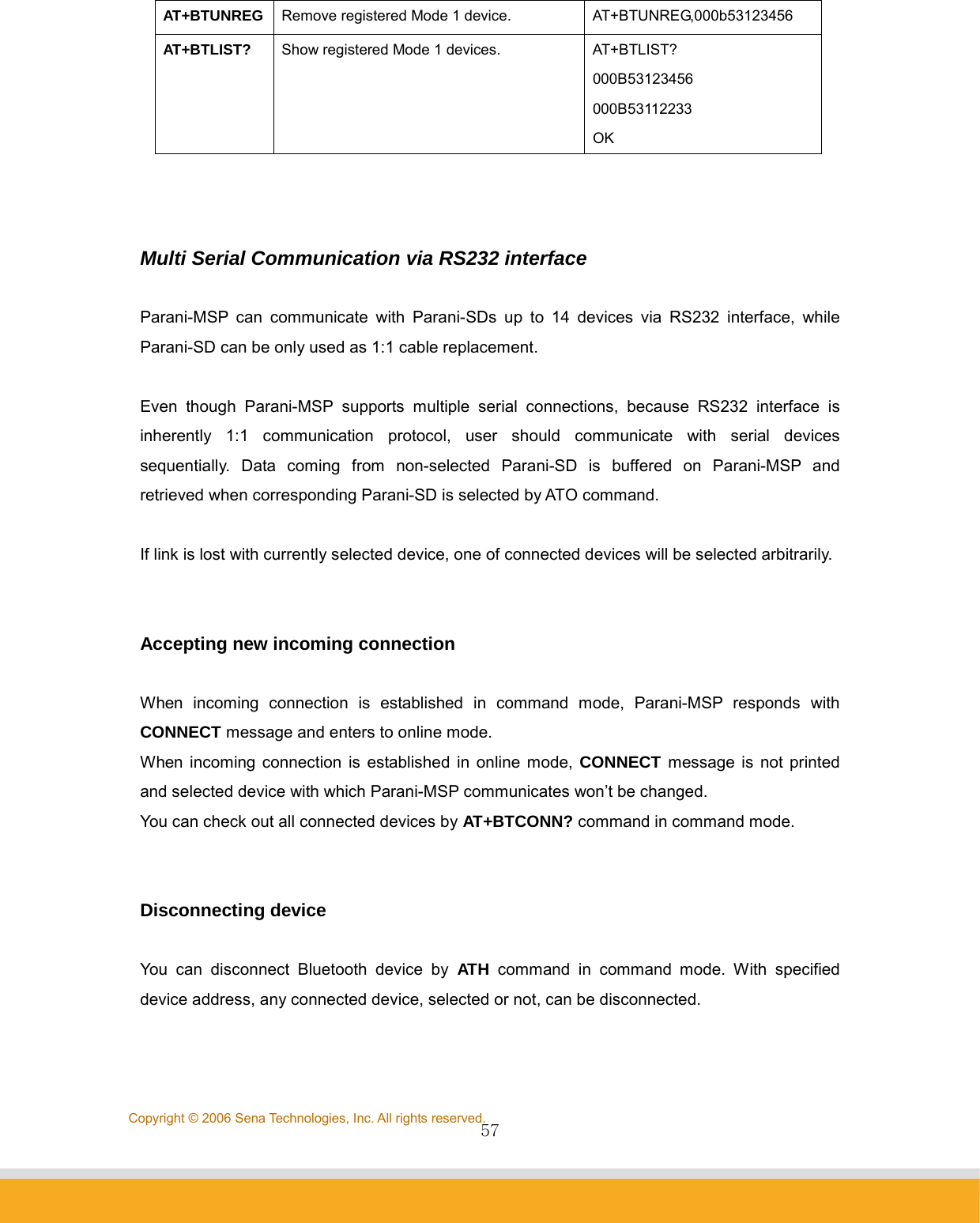
![46Copyright © 2006 Sena Technologies, Inc. All rights reserved.Ex.: DELSERV Parani-SD +OK REPT <interval> : When connection to Host is failed, users may configure Retrial period of connection. Unit: millisecond, Default value: 5000 ms If the value is ‘0’, Parani-MSP will try to recover connection only once. Ex.: REPT 3000 +OK REPEAT every 3000 ms PSIST <on|off> : In Client mode, in the event of TCP disconnection, Parani-MSP™ automatically attempts to recover TCP connection when PSIST is set to ON, in the period of pre-defined ms by REPT command. Ex.: PSIST ON +OK PERSIST on 5.4 Commands for Vertex Mode VERTEX <port no.> [number of clients] : To assign port number where Parani-MSP waits for connection in Vertex mode. Parani-MSP™ Vertex Mode avails Wireless RS485 multi-drop service when assigned at this site. Ex.: VERTEX 4000 1 +OK PORT 4000 MAX 1 5.5 Commands for Serial Hub Mode ROUTE <add> <src> <dst>](https://usermanual.wiki/Sena-Technologies/PARANIMSP100/User-Guide-707563-Page-46.png)
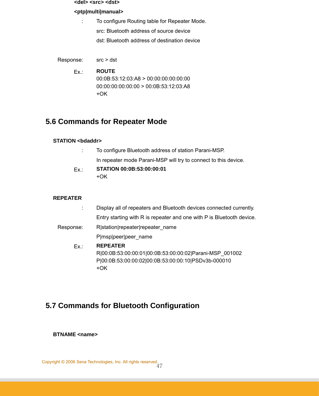
![49Copyright © 2006 Sena Technologies, Inc. All rights reserved.Ex.: LKEY 00:0B:53:20:00:63|00:08:1B:00:52:72 +OK TEMPKEY <on|off> : Some Bluetooth device doesn’t save their link key and makes new link key on every connection. This behavior causes Parani-MSP’s flash memory to wear out in the long period. With TEMPKEY on, Parani-MSP won’t save link key neither and protects itself. If you see tons of ‘Replacing hci0 link key xx:xx:xx:xx:xx:xx …’ messages on System Log, you should turn this option on. Ex.: TEMPKEY on +OK TEMPKEY +OK on SCAN [inquiry] [page] [noscan] : For Parani-MSP™ scan mode assignment. INQUIRY set to ON activates discoverable mode. PAGE set to ON activates connectable mode. Default SCAN displays current scan mode. Ex.: SCAN page +OK SCAN +OK page STAT : Displays current Bluetooth device status If any background task running, it will show [PENDING]. Response: idx|bdaddr|tx_byte|rx_byte|err_tx|err_rx Ex.: STAT 0|00:0B:53:20:00:63|1710|3513|0|0 +OK AFH [channel] … : This command will activate 802.11b Wi-Fi Combo mode, in which Parani-MSP doesn’t make use of the ranges of frequencies where co-existing](https://usermanual.wiki/Sena-Technologies/PARANIMSP100/User-Guide-707563-Page-49.png)
![50Copyright © 2006 Sena Technologies, Inc. All rights reserved.802.11b Wi-Fi devices work. Specify channel 0(zero) to disable combo mode. When enabled, overall throughput will be reduced. Ex.: AFH 10 11 +OK AFH +OK AFH 10 11 AFH 0 +OK 5.8 Commands for Bluetooth Connection Management LIST : To see connected Bluetooth device list. Higher link quality, better link status. Zero rssi means the most efficient RF condition (so called ‘Golden Range’). With link quality lower than 200, throughput may be affected or link may be lost. Response: idx|dev_id|port|bdaddr|name|tx_byte|rx_byte|link_quality|rssi Ex.: LIST 0|0|5000|00:0B:53:00:00:8A|SDv3b-00008A|0|0|255|0 +OK CONN <bdaddr> [channel] : Parani-MSP may try to CONNECT to Bluetooth devices. If you specify a channel, Parani-MSP will try connection directly skipping SDP (Service Discovery Protocol) process. Each device to connect should be in connectable mode. Ex.: CONN 00:0B:53:00:00:8A +OK](https://usermanual.wiki/Sena-Technologies/PARANIMSP100/User-Guide-707563-Page-50.png)
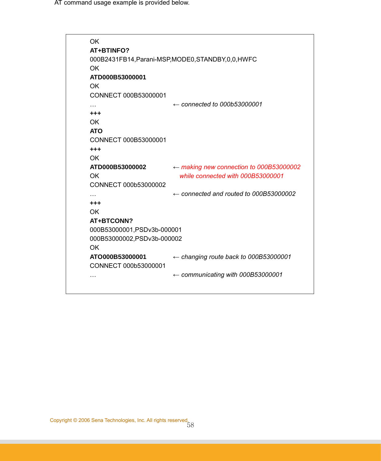
![52Copyright © 2006 Sena Technologies, Inc. All rights reserved.<IAC>: Inquiry Access Code. Users may inquire the device with same IAC code. In Bluetooth specification, there are General IAC (0x9E8B33) and Limited IAC (0x9E8B00). Ex.: PINQ on 20 5 0x9E8B33 +OK NGBRH : To see the inquired device list by PINQ command. Response: bdaddr CoD name Ex.: NGBRH 00:0B:53:00:00:E5 0x001f00 PSDv3b-0000E5 00:0B:53:20:00:79 0x020300 Parani-MSP +OK DTINFO <on|off> : The information of the corresponding data terminal is sent from Parani-MSP prior to any data transmission when TCP socket connected. It consists of Bluetooth address and name in fixed length with NULL padding following. Available in server mode or client mode. Response: bdaddr,name<null-padding> (64bytes fixed-length) 000B53123456,PSDv3b-123456 Ex.: DTINFO on +OK FWDT <tx_timeout> <rx_timeout> [init] : Reboot itself if no change in TX bytes for more than <tx> seconds, or in RX bytes for more than <rx> seconds after [init] seconds from booting. If init is not specified, timer won’t start till any data transaction. These values accept 0 for disabling each function. [init] can be just omitted to disable the function. Ex.: FWDT 0 10 +OK](https://usermanual.wiki/Sena-Technologies/PARANIMSP100/User-Guide-707563-Page-52.png)
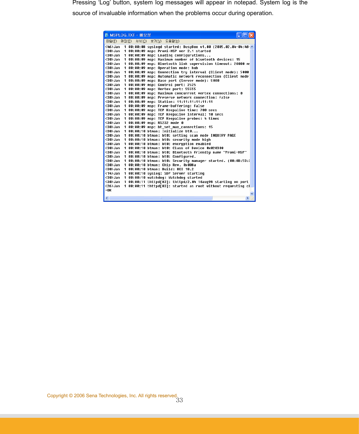
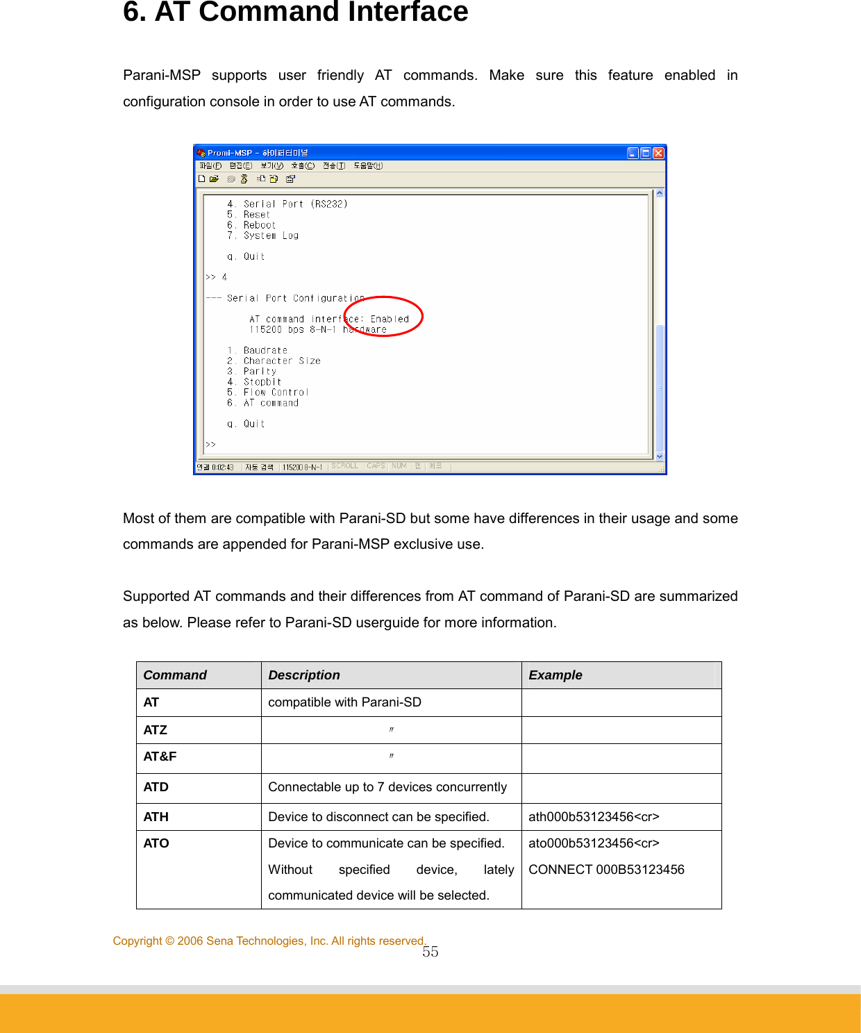
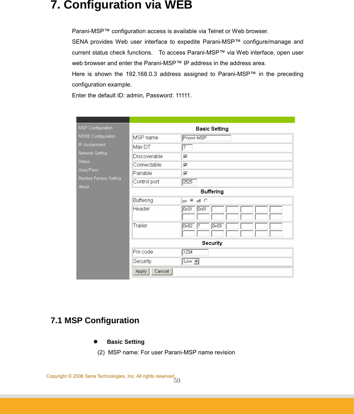
![53Copyright © 2006 Sena Technologies, Inc. All rights reserved. 5.9 Other Commands DUMP [idx] [bin] : This command shows data that flows between Host and Bluetooth devices. [idx]: To select a specific device to monitor. (255 means all of devices) [bin]: To display data in binary format. format: <dir:1><idx:1><length:2><timestamp:4><data… :length> timestamp: in milliseconds Ex.: DUMP > line 0 len 4 timestamp 1413986 61 62 63 64 abcd < line 0 len 4 timestamp 1414056 4F 4B 0D 0A OK.. +OK LOG [line] : LOG displays system logs. If line number specified, only latest <line> rows will be displayed. Ex.: LOG <30>Jan 1 00:00:09 msp: Parani-MSP ver 2.3 started <30>Jan 1 00:00:09 msp: Loading configurations… … +OK HELP : HELP command displays all control commands available. Ex.: HELP +OK VER : To see software version no. of Parani-MSP Ex.: VER +OK Ver 2.3](https://usermanual.wiki/Sena-Technologies/PARANIMSP100/User-Guide-707563-Page-53.png)
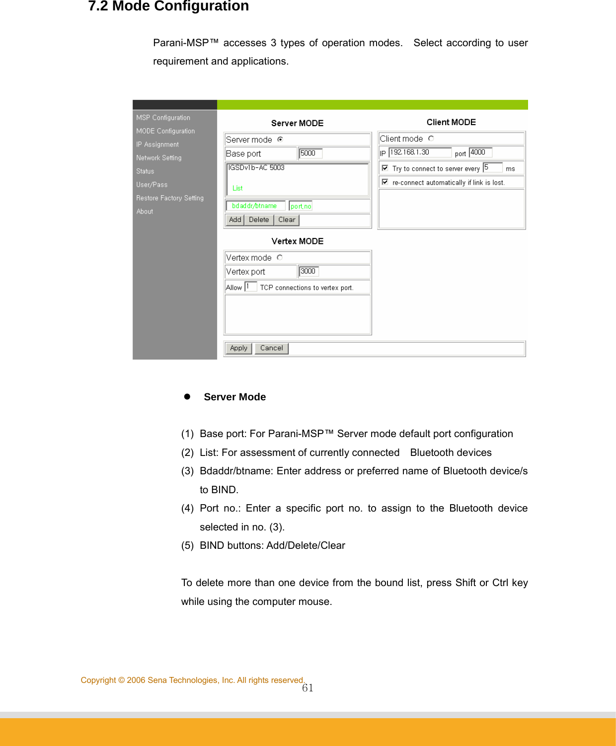
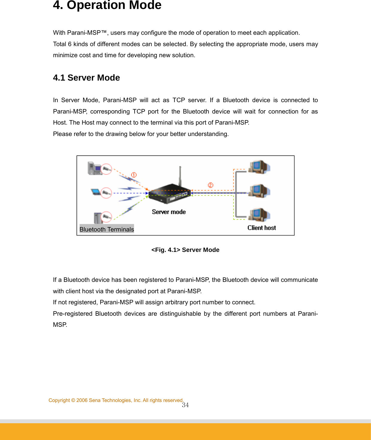
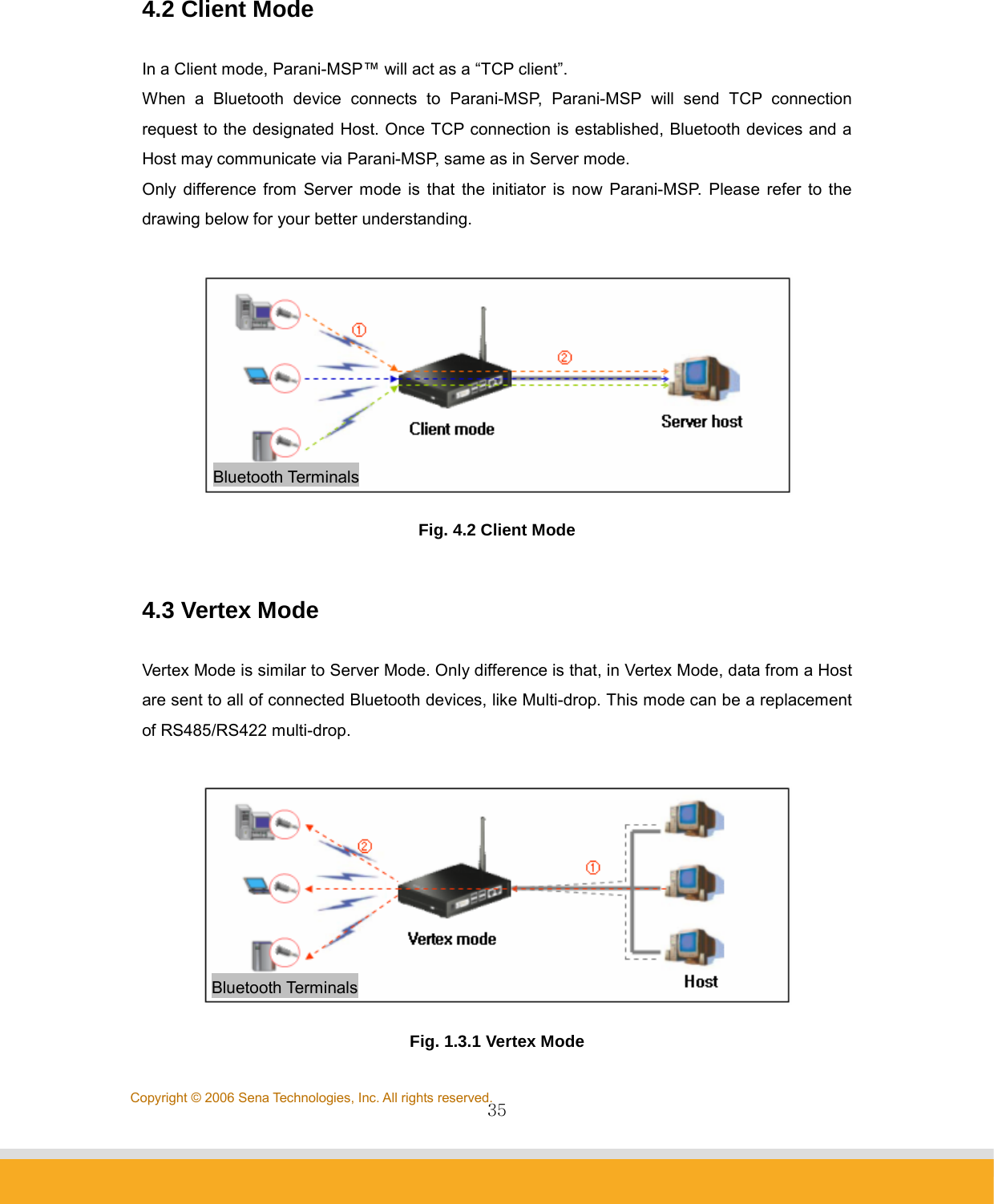
![62Copyright © 2006 Sena Technologies, Inc. All rights reserved. z Client Mode In Client Mode, Parani-MSP™ operates as client initiating TCP connection request. Host PC becomes a server. (1) IP: For network Host Server IP address entry (2) Port: For Server Host port no. entry (3) [ ] Try to connect to server every [ ] ms: When Parani-MSP™ fails to open a data channel connecting to Host, enter the connection retry frequency. Entering 0 [zero] obtains retry abort. (4) [ ] re-connect automatically if link is lost. For Host connect retry, if failed. Retry frequency is set in the preceding function. z Vertex Mode In Vertex Mode, data from a Host are sent to all of connected Bluetooth devices, like Multi-drop. (1) Vertex port: For Parani-MSP™ Vertex port no. entry. (2) Allow [ ] TCP connections to vertex port: For entering the number of Hosts connectable to Parani-MSP™. 7.3 IP Assignment Parani-MSP™ LAP service use renders assignable IP numbers for LAN access](https://usermanual.wiki/Sena-Technologies/PARANIMSP100/User-Guide-707563-Page-62.png)
![63Copyright © 2006 Sena Technologies, Inc. All rights reserved.service Bluetooth devices configuration. Set IP address and subnet mask Start number; Parani-MSP™ automatically assigns IP to connected Bluetooth devices. 7.4 Network Setting For user Parani-MSP™ network setting. (1) [ ] use DHCP: When checked, Parani-MSP™ receives IP address from DHCP server. (2) IP address/Network mask/Gateway/DNS: Enter appropriate data to assign static IP address for Parani-MSP™. (3) MAC: Displays MAC Parani-MSP™ address; non-user entry (4) [ ] use ADSL: Select this option when ADSL networking (5) User/Pass: Enter ID/password data for ADSL login.](https://usermanual.wiki/Sena-Technologies/PARANIMSP100/User-Guide-707563-Page-63.png)