SIEPEM Technology CJ-100 IP CAMERA WITH WI-FI User Manual 5030 M Camera
Shenzhen SIEPEM Technology Co., Ltd IP CAMERA WITH WI-FI 5030 M Camera
User Manual
IP CAMERA
Chapter 1 Features
NEW
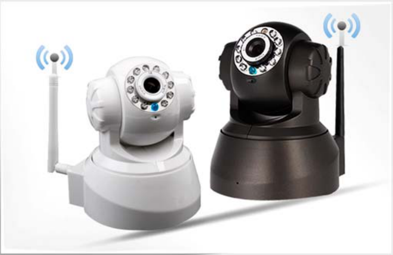
CJ-100 is the latest model developed by SIEPEM, Inc., it is suitable for family,
offices and chain store monitoring. It is the latest version.
●P2P (peer to peer) technology, without annoying IP settings simply fill out the
ID number can be obtained surveillance video.
●Wi-Fi compliant with wireless standards IEEE 802.11b/g;
●Suport Pan/Tilt control up and down,rotation, auto-cruise from different
angles (Pan:355°& Tilt:120°);
●Auto IR-LED illumination for night vision (up to 10 metres);
●Nice blue indicator light ;
●Two-dimensional code scanning functions.
Chapter 2 Installation
2.1
1) First: connect the camera with hub, switch or router by Cat.5 straight-through
cable or cross-over cable with standard RJ-45 interface.
2) Second: connect the camera with power supply by the adaptor supplied (DC5V,
2A).
Caution: Please ensure that the adaptor matches with the electricity (Input: AC 100V
or 220V, Output: 5V DC/2A).
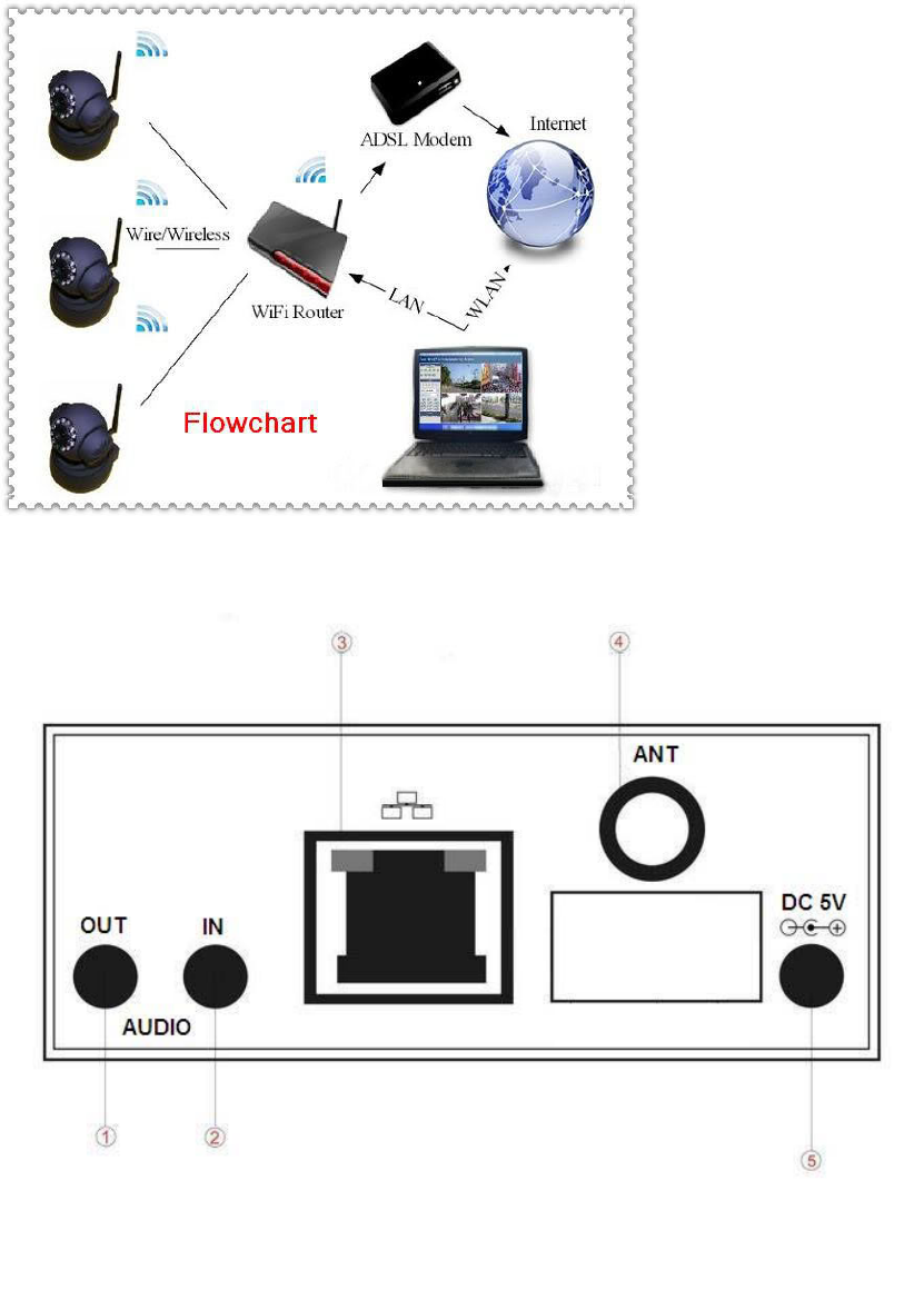
2.2 Interface
Chapter 3 Cellphone monitor
3.1 cellphone must be connected to the internet(WIFI/GPRS/3G)
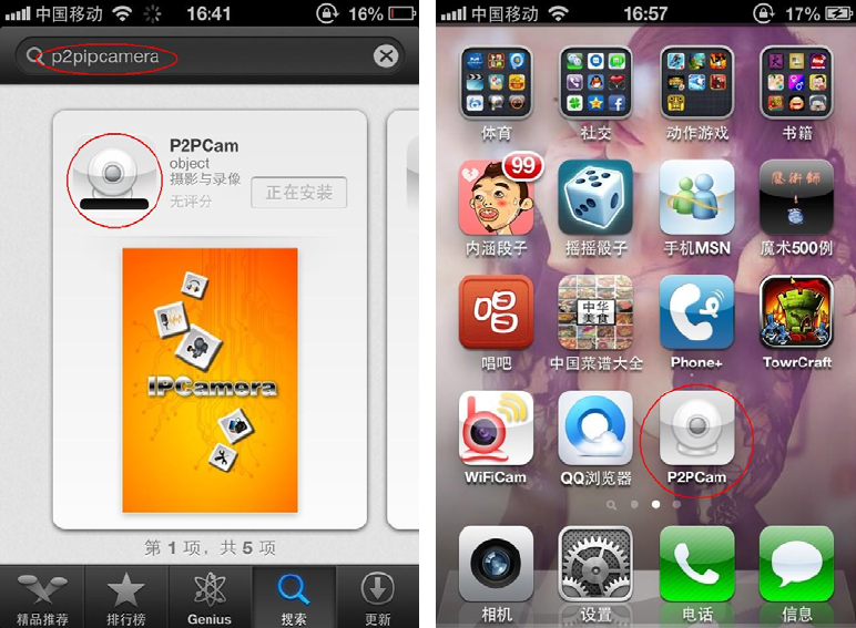
3.2 install software on your cellphone
Android:Acquire software from CD.
Iphone:Acquire “P2Pwificam” from App Store. You can search for “P2Pwificam”
(This application supports Iphone system that is higher than 4.3 released.)
3.3 Add Camera:
“Add Camera” click “+”
Enable users to edit camera ID, user's name and password setting and the
change of equipment alias .
“Scan”Two-dimensional code scanning acquire camera ID.
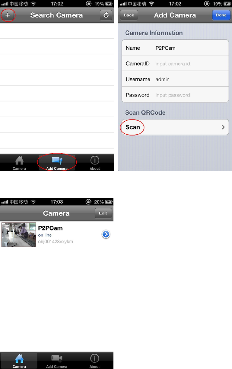
3.4 Device list.
3.5 Function:
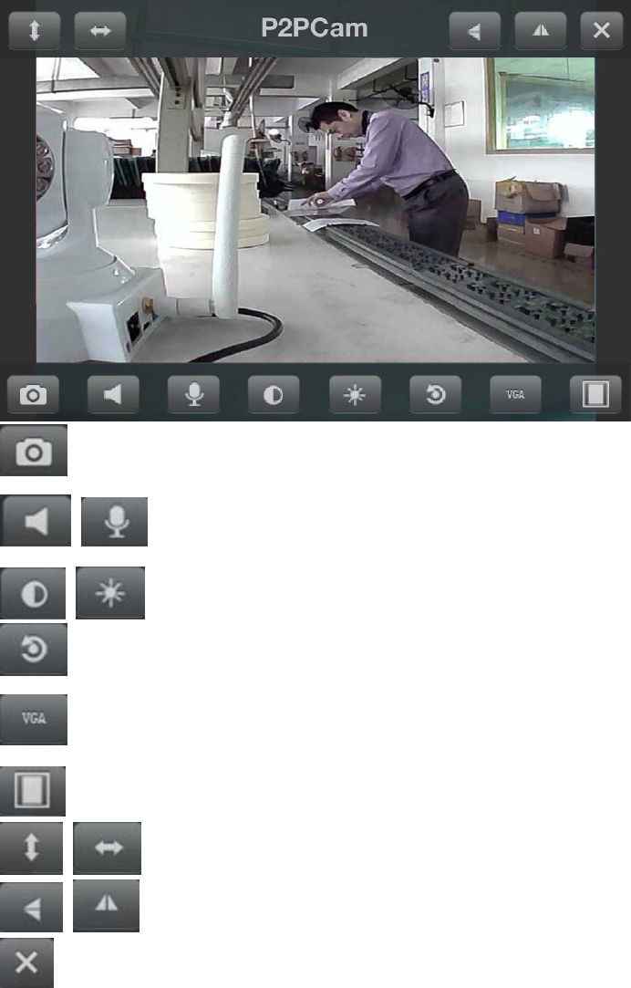
snapshot
speaker/mic (can not be open at the same time)
birghtness/contrast
restore the default
resolution : VGA(640×480)QVGA(320×240)
ratio
cruise
Flip /Mirror
close
touch screen to control PTZ
Chapter 4 PC Software Instruction
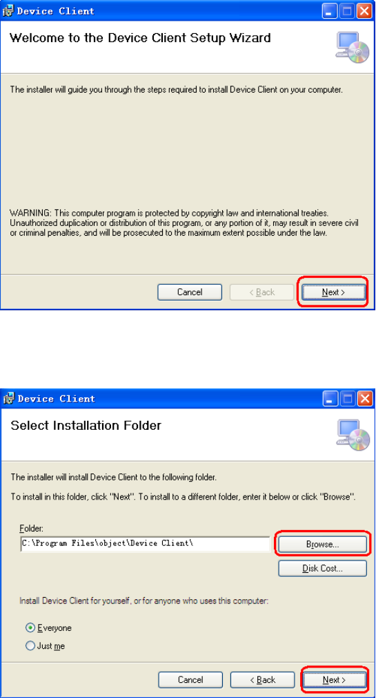
4.1 Find “MonitorClient.msi” in the CD and run it like below pic.
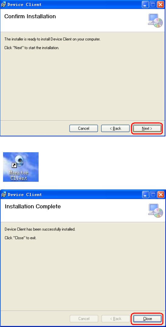
4.2
Click "Browser" to select setup path(default path "C:\Program Files\object\Device
Client "),then click "Next" like below pic.
4.3 Click "Next",then go the below pic.
4.4 Click "Finish" to end the setup,at the time it will come up this icon in the desktop
“”.
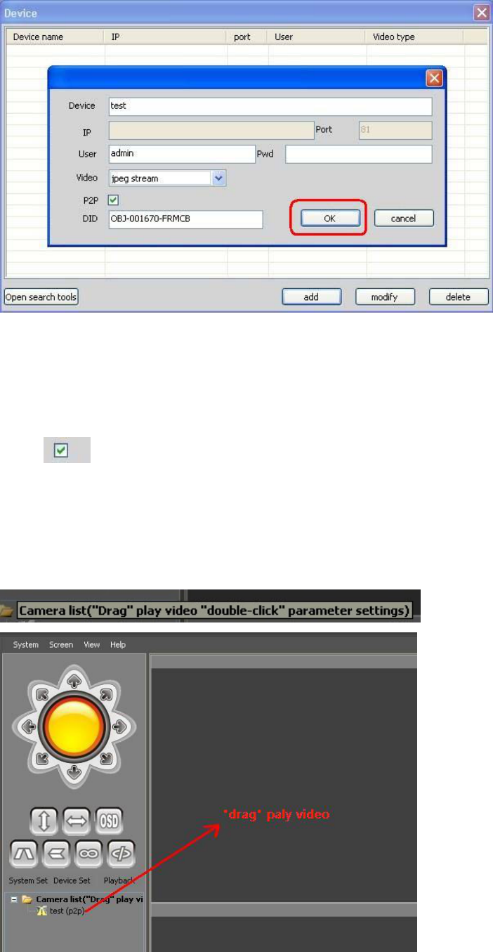
4.5 Click“System—Device list”
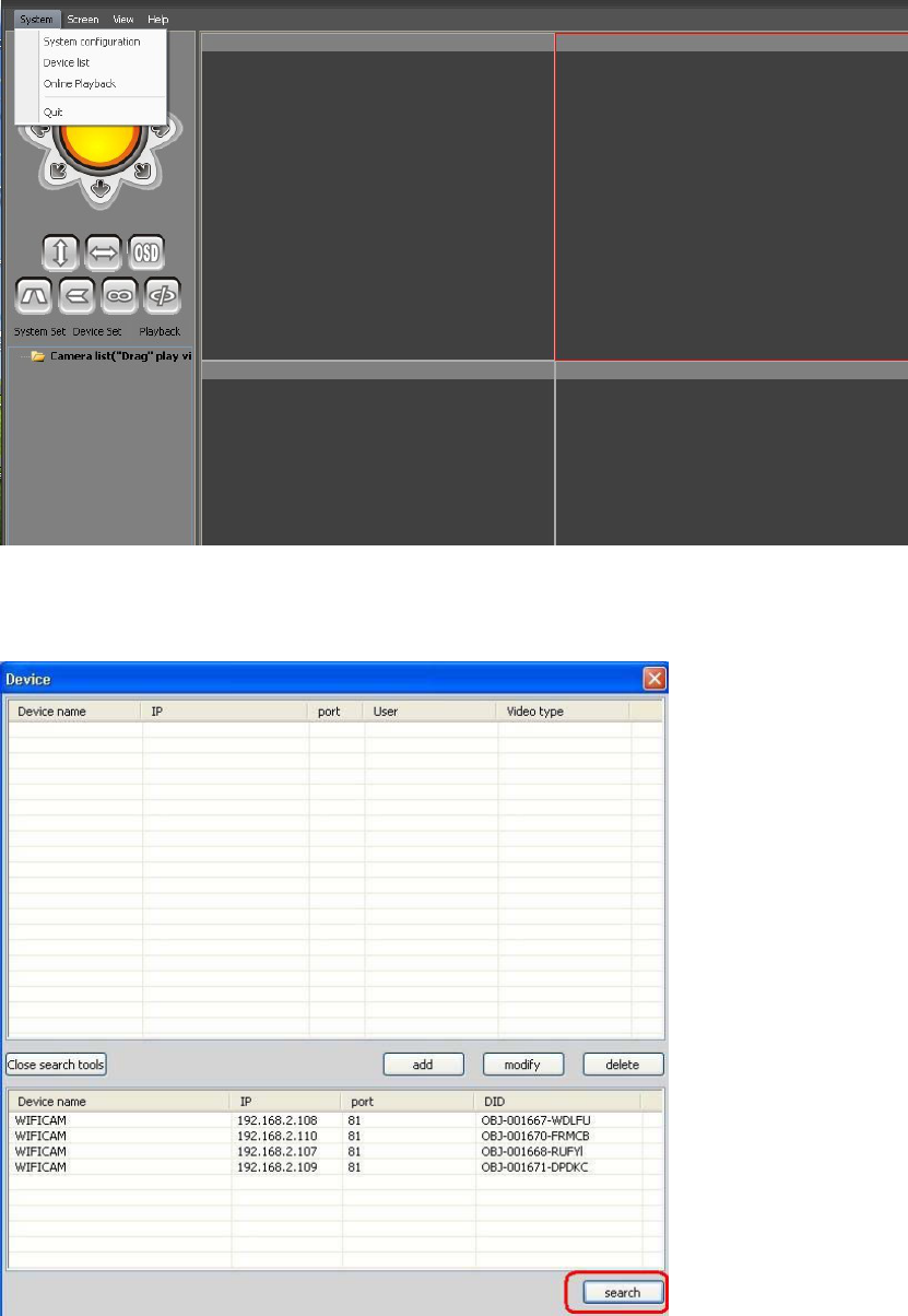
4.6 Add a lan camera :
Open search tools,click “search”
IP acquisition:
① Confirmed that the device is turned on and connected to the network
normal.
② LAN or PC support DHCP(Dynamic IP allocation),because the
camera's factory settings dynamically IP, LAN or PC does not open DHCP, occurs
not search the camera IP.
Double click IP address,,then go the below pic,“OK”.
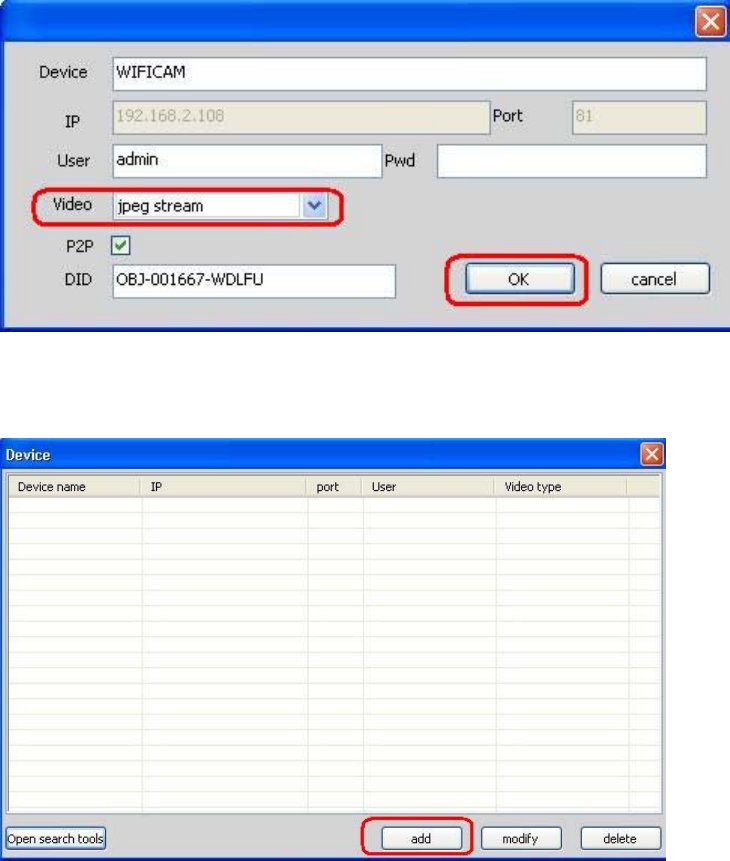
4.7 Add a remote camera:
click“add”,then go the below pic:
Device:The names of equipment, which can help you identify different devices, for
examples, you can type the names based on the location of the equipment.
User:Usually the default is "admin";
Pwd:he default of password is usually as " ",
Video:According to the machine model selection(model 5030:mjpeg)
P2P:
DID:camera ID(search in lan)
Click "OK" to end the setup.
4.8 paly Video
drag (Device name) play video
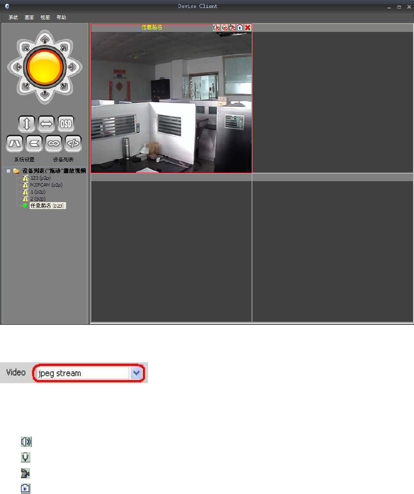
Note:Select the correct video stream ,For example :MJPEG
4.9
Speaker(For audio ip camera only)
Mic(For audio ip camera only)
record
snapshot
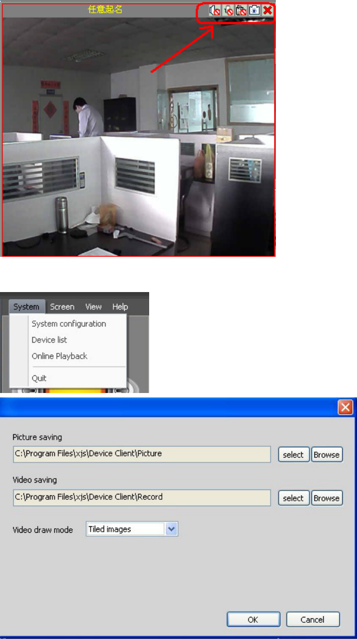
4.10 “System—System configuration”.

4.11 Screen:1/4/9/16/25/36/49/64/Full Screen
4.12 Function keys
Control the PT(For PT ip camera only)
cruise(For PT ip camera only)
cruise(For PT ip camera only)
OSD:Display the camera name and time
Flip /Mirror
IO closed(For IO ip camera only)

IO Open(For IO ip camera only)
Chapter 5 camera parameter setting
Double-click (Device name)parameter setting
5.1 Base Info
Click“Get”Base Info
Allas:Device name
Device Firmware
Device ID
Device Alam Status
UPNP Status
DDNS Status
MAC Adress
WIFI MAC Adress
Click“Get” Display device information
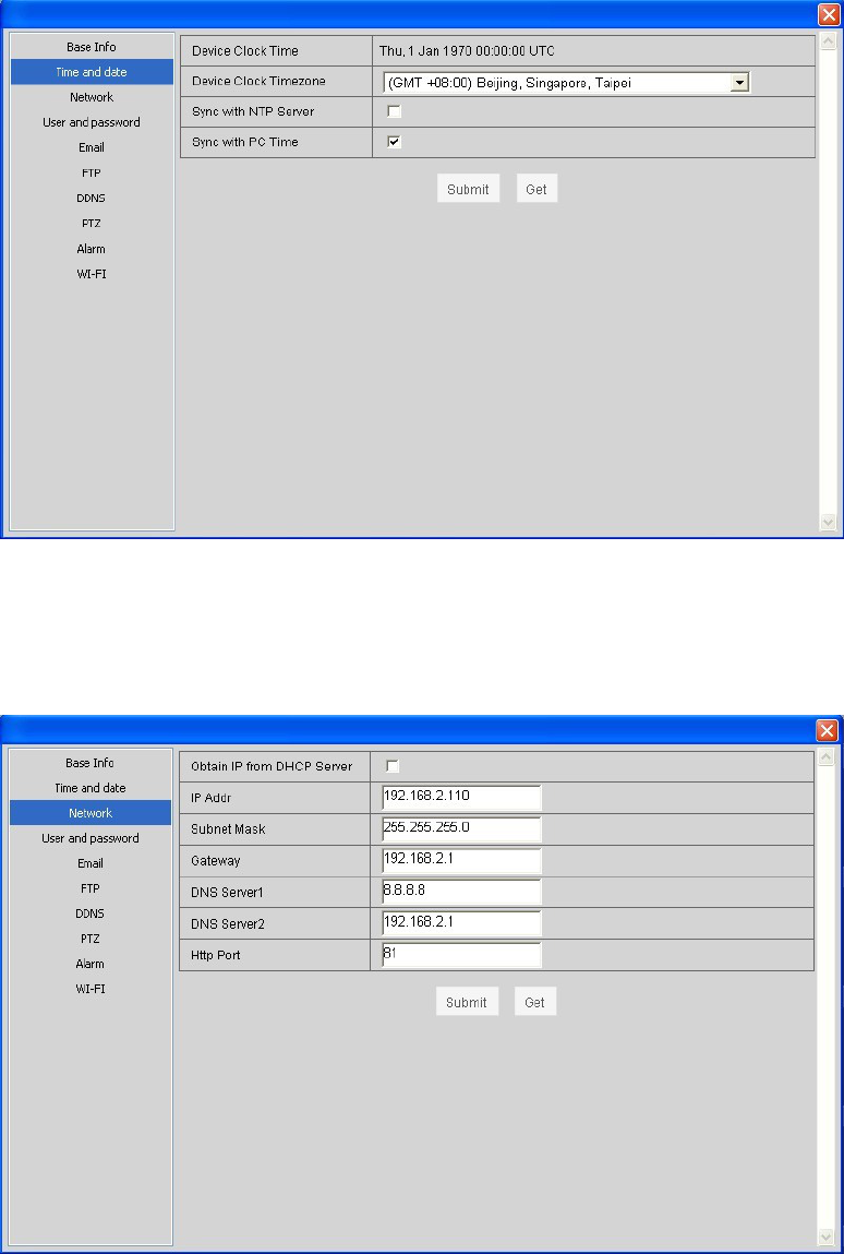
5.2 Time and date
Obtain the time from a PC or from the server to get the time, if there is no access to
the Internet only get from the PC.
click“Submit” Save the settings,click“Get” The new setting is displayed.
5.3 Network
Set the subnet mask, gateway, and DNS server; following figure check DHCP, the
device can automatically obtain an IP address.
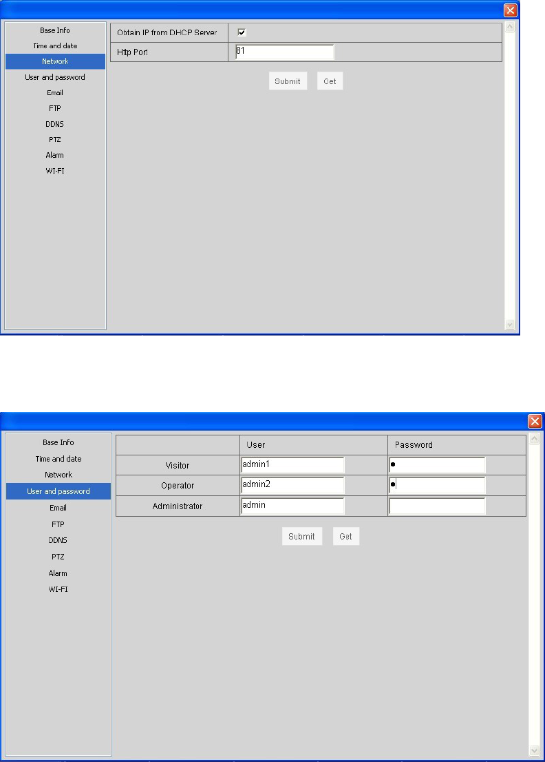
click“Submit” Save the settings,click“Get” The new setting is displayed.
5.4 User and Password
Administrator,Visitor and Operator
Administrator:All permissions
Visitor:only view the video and switch the screen.
Operator:In addition to not enter the interface of the device parameters, have other
privileges.
click“Submit” Save the settings,click“Get” The new setting is displayed.
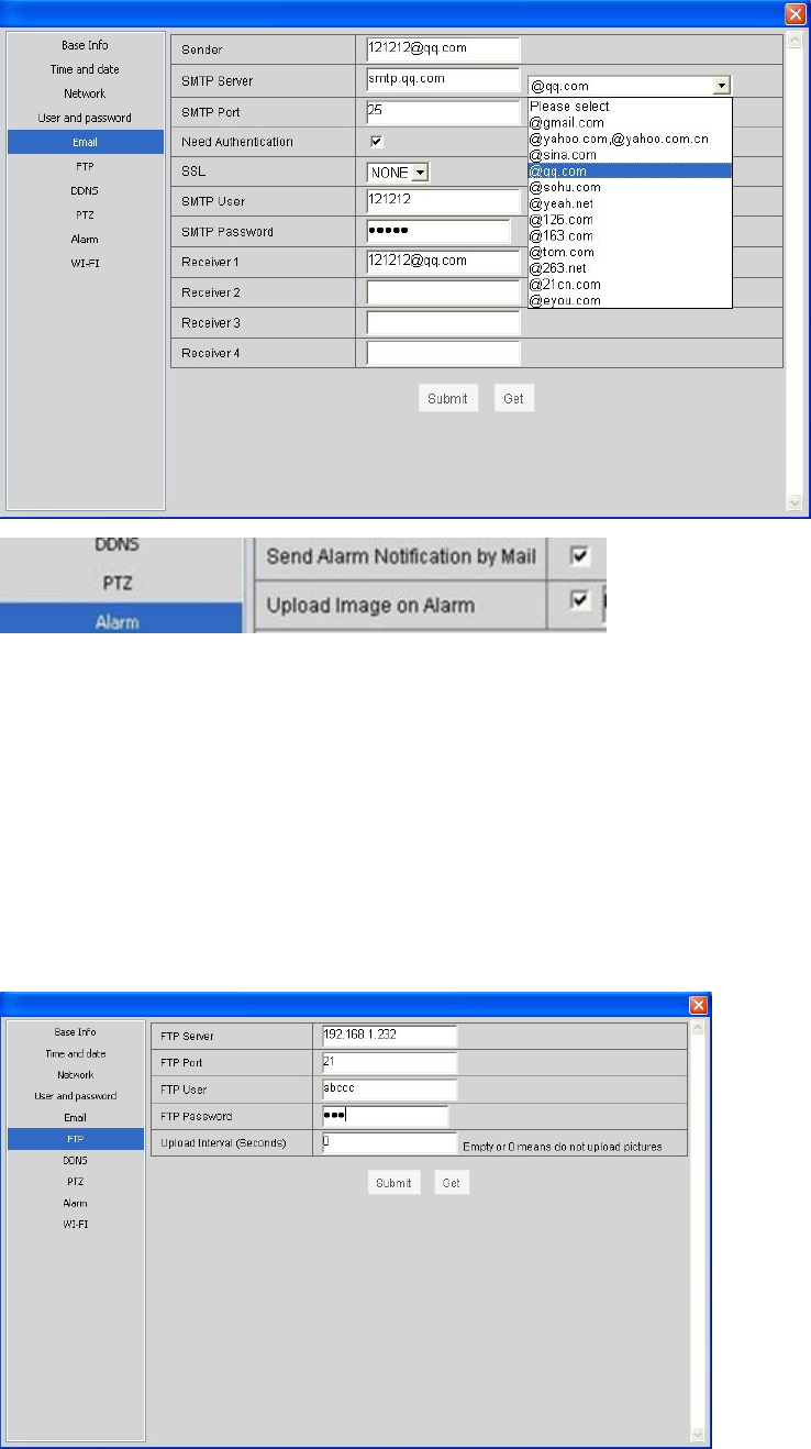
5.5 Mail Service Settings
If the camera is connected to the Internet, set this function.
Sender: input a valid email address to send pictures when alarm triggered;
SMTP Server: the website your mail(sender);;For example QQmail:smtp.qq.com
SMTP Port:the website Port your mail(sender)
SMTP User and Password: the user and password of the sender (email account and
password).
Receiver: input a valid e-mail address to receive pictures when alarm triggered. Now
it supports up to 4 receivers.
click“Submit” Save the settings,click“Get” The new setting is displayed.
5.6 FTP
Ftp service is used to send the captured pictures when alarm triggered to ftp server
and save them. If the camera is not connected to the Internet, there is no need to set
this function.
FTP Server: the website you want to upload the picture to;
FTP Port: 21
FTP User: user name to login ftp server;
FTP Password: password to login ftp server;
Upload Interval (Seconds): set the upload interval; unit: second.
click“Submit” Save the settings,click“Get” The new setting is displayed.
5.7 DDNS
Acquire a dynamic domain name;
For example:Logon www.dyndns.com.
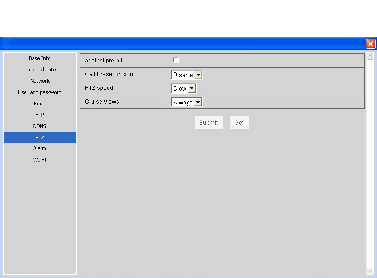
5.8 PTZ
Rotating speed
click“Submit” Save the settings,click“Get” The new setting is displayed.
5.9 Alarm
Motion Detect Armed: Moving objects trigger alarm;
Motion Detect Sensibility can be selected as 1~10 with sensitivity increasing;
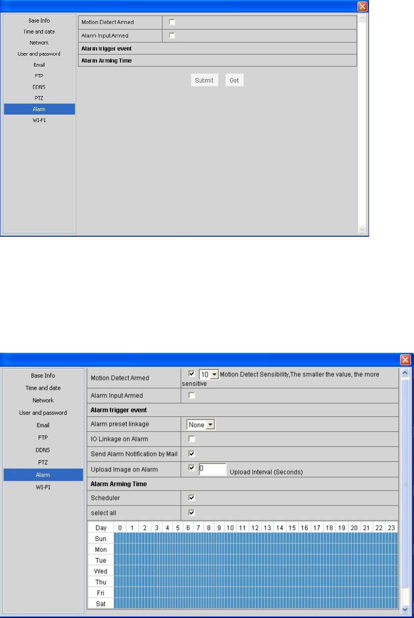
Alam preset linkage
IO Linkage on Alarm: when alarm triggered, it will link the external device connected
with IO port;(For IO ip camera only)
Send Alam Notification by Mail:snapshot and send email on alarm. For details,
please refer to “Mail Service Settings”;
Upload Image on Alam:Upload images to ftp server on alarm. Upload Internal can be
set. For details, please refer to “Ftp Service Settings”;
click“Submit” Save the settings,click“Get” The new setting is displayed.
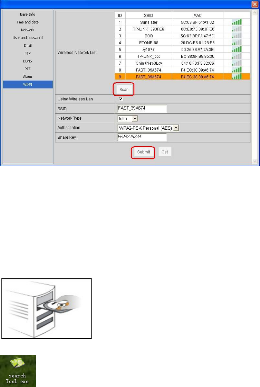
5.10 WI-FI setting
Please select Wireless Lan Settings and click“Scan”. Then the camera scans the
WLAN nearby and lists the results.
you can fill in the Keys according to the wireless network settings of your wireless
router. Select None if no encryption is set.
As it’s correctly set, please pull out the network cable and the camera will reboot.
click“Submit” Save the settings,click“Get” The new setting is displayed.
Chapter 6 Web
6.1
Use of computers and cameras within a LAN
1) Open the CD
2) copy to desktop
double-click the above icon and a dialogue box appears: the IP address of
the camera will appear after several seconds later.
IP acquisition:
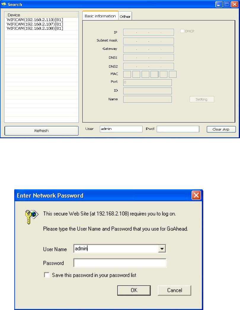
① Confirmed that the device is turned on and connected to the network
normal.
② LAN or PC support DHCP(Dynamic IP allocation),because the
camera's factory settings dynamically IP, LAN or PC does not open
DHCP, occurs not search the camera IP.
6.2 Login
Input the URL (for example, http://192.168.2.108:81) or enter the home page
by ip camera tool mentioned above.
Input the user name and password (default user: admin; no password). Click
“OK” and enter the monitoring page (Max. 4 users viewing simultaneously).
Language optional: Traditional and Simplified Chinese, English, Russian, Deutsch.
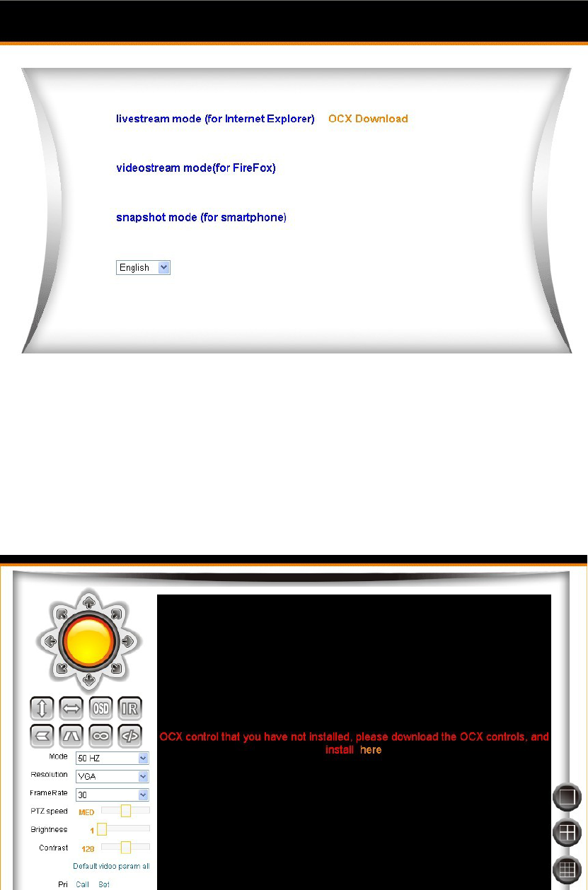
Note: There are three modes optional for different applications. Please select one
according to your web browser.
6.3
If it’s the first time a camera being viewed in a PC, .an OCX file needs installing in
the PC. Please download OCX file and install it. Next, please refresh the page and
login again.
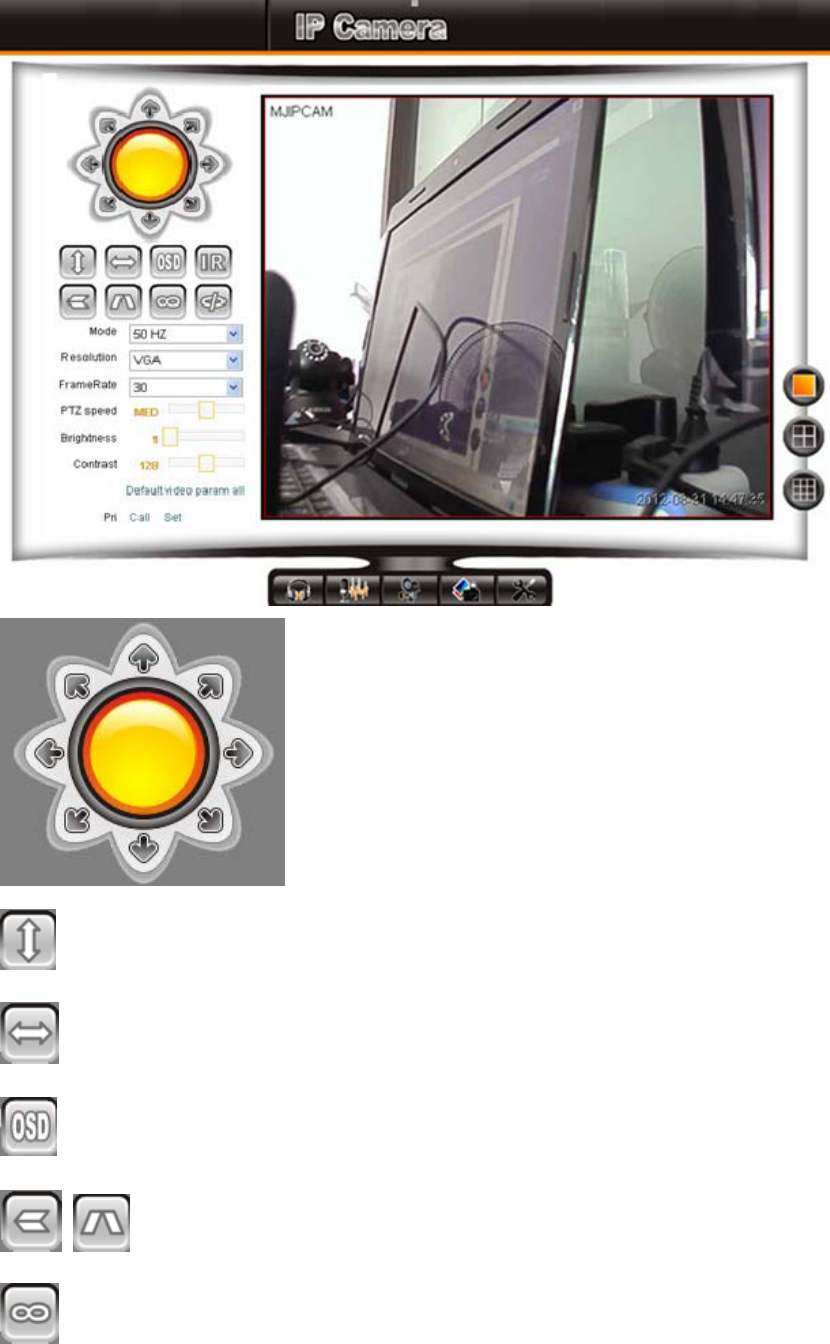
6.4 Function keys
Control the PT(For PT ip camera only)
cruise(For PT ip camera only)
cruise(For PT ip camera only)
OSD:Display the camera name and time
Flip /Mirror
IO closed(For IO ip camera only)

IO Open(For IO ip camera only)
Mode: 50HZ/60HZ
Resolution: VGA(640×480)and QVGA(320×240)
Frame rate:1-30
PTZ Speed
Brightness
Contrast
Default video param all
Preset
1/4/9CH
:Speaker(For audio ip camera only)
:Speaker/ Mic two-ways audio(For audio ip camera only)
:Record
:Snapshot
:parameter setting
Federal Communications Commission (FCC) Statement
This device complies with part 15 of the FCC Rules. Operation is subject to the following two
conditions: (1) This device may not cause harmful interference, and (2) this device must accept
any interference received, including interference that may cause undesired operation.
Note: This equipment has been tested and found to comply with the limits for a Class B digital
device, pursuant to part 15 of the FCC Rules. These limits are designed to provide reasonable
protection against harmful interference in a residential installation. This equipment generates, uses
and can radiate radio frequency energy and, if not installed and used in accordance with the
instructions, may cause harmful interference to radio communications. However, there is no
guarantee that interference will not occur in a particular installation. If this equipment does cause
harmful interference to radio or television reception, which can be determined by turning the
equipment off and on, the user is encouraged to try to correct the interference by one or more of
the following measures:
z Reorient or relocate the receiving antenna.
z Increase the separation between the equipment and receiver.
z Connect the equipment into an outlet on a circuit different from that to which the receiver is
connected.
z Consult the dealer or an experienced radio/TV technician for help.
Warning: Changes or modifications made to this device not expressly approved by Shenzhen
SIEPEM Technology Co., Ltd may void the FCC authorization to operate this device.
Note: The manufacturer is not responsible for any radio or tv interference caused by unauthorized
modifications to this equipment. Such modifications could void the user’s authority to operate the
equipment.
The transmitter must not be co-located or operated in conjunction with any other antenna or transmitter.
This equipment complies with the FCC RF radiation exposure limits set forth for an uncontrolled environment.
This equipment should be installed and operated with a minimum distance of 20cm between the radiator and
any part of your body.