SkyRC Technology D100V2 AC/DC Dual Balance Charger/Discharger/Power Supply User Manual SK D100 V2
SKYRC Technology Co., Ltd. AC/DC Dual Balance Charger/Discharger/Power Supply SK D100 V2
User Manual
Instruction Manual
[Version 1.0]
AC/DC Dual Balance Charger
Discharger / Power Supply
V2

Table of Contents
This appliance is not intended for use by persons (including children) with
reduced physical, sensory or mental capabilities, or lack of experience
and knowledge, unless they have been given supervision or instruction
concerning use of the appliance by a person responsible for their safety.
Children should be supervised to ensure that they do not play with the
appliance.
Do not recharge non-rechargeable batteries!
WARNING:
INTRODUCTION
SPECIAL FEATURES
WARNING AND SAFETY NOTES
PROGRAM FLOW CHART
OPERATION
POWER AND BATTERY CONNECTION
OPERATING PROGRAM
LITHIUM BATTERY PROGRAM (LIPO/LIFE/LILON/LIHV)
NIMH/NICD BATTERY PROGRAM
PB LEAD-ACID BATTERY PROGRAM
DC POWER SUPPLY
BATTERY MEMORY SET AND CALL OUT
SYSTEM SETTING
BATTERY VOLTAGE METER
BATTERY RESISTANCE METER
WARNING AND ERROR MESSAGE
USING THE CHARGE CONTROL SOFTWARE “CHARGE MASTER”
THESETCONTAINS
SPECIFICATION
CONFORMITY DECLARATION
COMMONLY USED TERMS
WARRANTY AND SERVICE
01
03
06
09
10
11
13
15
18
22
24
25
27
29
30
31
32
32
33
34
35
36

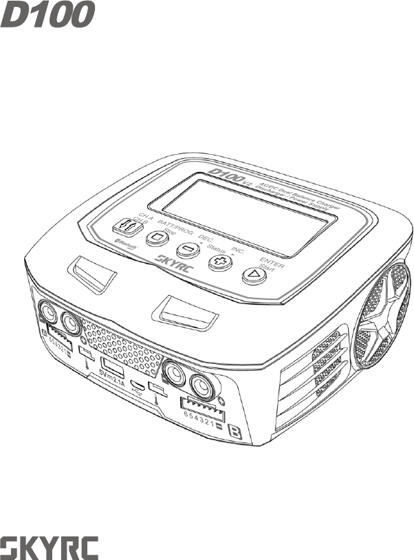
Congratulations on your choice of SKYRC D100 V2 AC/DC Dual Balance
Charger/Discharger/Power Supply. This unit is simple to use, but the operation
of a sophisticated automatic charger such as SKYRC D100 V2 does require
some knowledge on the part of the user. These operating instructions are
designed to ensure that you quickly become familiar with its functions. It is
therefore important that you read right through the Operating Instructions,
Warning and Safety Notes before you attempt to use your new charger for the
first time. We hope you have many years of pleasure and success with your
new battery charger.
SKYRC D100 V2 is a twin-channel charger with two independent circuits which
can charge batteries of varying chemistries (NiMH/NiCd/LiPo/LiFe/Lilon/LiHV/
Pb) simultaneously. Capable of operating as a power supply with the maximum
output of 100W helps the drivers & hobbyists to power the car measurements
and tools everywhere. With its unprecedented function of voice guide, even a
freshman can operate this charger without any hurdles. Additional feature
including our "Scan to go" function, providing an opportunity of feeling
intellectualized control to operate your charger via personal smart phone app
after connected via Bluetooth 4.0 built-in.
SKYRC D100 V2 is a high-performance, micro processor control charge/
discharge/power supply station with battery management suitable for use with
all current battery types, it is with integral equalizer for six-cell Lithium-Polymer
(LiPo), Lithium iron phosphate(LiFe) and Lithium-Ion (LiIon) batteries with max
10A charge current and max 100W charge power. The additional LiHV mode is
able to charge the new generation of LiPo batteries with an end of charge
voltage 4.35V.
Please BE SURE to read these INSTRUCTIONS, WARNING and SAFETY
NOTES before you use the charger for the first time.
It can be dangerous to mis-handle batteries and battery chargers, as there is
always a risk of batteries catching fire and exploding.
Introduction
01 ·
D100 V2
Mishandling batteries and battery chargers is extremely dangerous, which
may cause fire and explosion.
Introduction
· 02 D100 V2
Please read this entire operating manual completely and attentively before
using this product, as it covers a wide range of information on operating and
safety. Or please do use this product in company with a specialist!
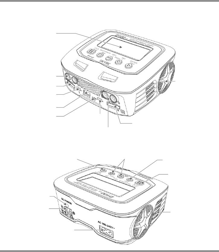
LCD Display
Output Socket
4mm Banana Plug
Balance Lead Socket
Temperature
Sensor Port
USB Port
Micro USB Port for
PC Link /
firmware upgrade
Temperature
Sensor Port
Output Socket
4mm Banana Plug
Balance Lead Socket
Cooling Fan
AC Input
100-240V
Switch from
Channel A to B or
Channel B to A
Resume or Start
Charge Processes
DC Input: 11-18V
DC Output: 13.8V
DC Power
LED Light
Scroll Through the
Main Menu Stop Any
Charge Processes
Alter Values
See the Status of Individual
Cells in Balance Charge Mode
Speaker System
03 ·
D100 V2
Twin-channel Charger
SKYRC D100 V2 allows you to plug 2 batteries into one charger simultaneously, and it
will intelligently and automatically charge 2 battries at once to their maximum capacity. To
top of it, the batteries being charged do not even need to have the same configuration.
You can connect different chemistry(NiMH/NiCd/LiPo/LiFe/Lilon/LiHV/Pb)batteries into
any of the charging ports.
Dual Input and Power Distribution
Optimized Operating Software
SKYRC D100 V2 features the so-called AUTO function that sets the feeding current
during the process of charging or discharging. Especially for lithium batteries, it can
prevent the overcharging which may lead to an explosion due to the user's fault. It can
disconnect the circuit automatically and alarm once detecting any malfunction. All the
programs of this product were controlled through two way linkage and communication, to
achieve the maximum safety and minimize the trouble. All the settings can be configured
by users!
Special Features
DC Power Output Supported
With the unique feature of power source, the user and driver does not have to take a big
and heavy power supply for race and play outside. The charger is compatible with our
mini partner DC power distributor(Optional part) with 3 output ports and 2 USB ports as
well for powering pit light, corner weight system, mobile phone, and iPad. etc. One
charger for ALL.
The input of SKYRC D100 V2 is AC 100-240V and DC 11-18V. In DC mode, the power of
each channel is 100W. Total power is 200W.
In AC mode, it supports power distribution, for example, if both channel A and channel B
are set to 40W, then, the DC power is 20W. the total power is 100W

Special Features
· 04 D100 V2
Internal Independent Lithium Battery Balancer
SKYRC D100 V2 employs an individual-cell-voltage balancer. It isn't necessary to
connect an external balancer for balance charging.
Balancing Individual Cells Battery Discharging
During the process of discharging, SKYRC D100 V2 can monitor and balance each cell of
the battery individually. Error message will be indicated and the process will be ended
automatically if the voltage of any single one cell is abnormal.
Adaptable to Various Type of Lithium Battery
SKYRC D100 V2 is adaptable to various types of lithium batteries, such as LiPo, LiIon
and the new LiFe series of batteries.
LiHV Mode Available
The additional LiHV mode is able to charge the new generation of LiPo batteries with an
end of charge voltage 4.35 V.
Smart Phone Control via Bluetooth Module (both iOS and Android)
Finally, your charger gets its own apps. The charger can be operated with a smart phone
via bluetooth connection. The smart phone APP features a "Scan to go" function that lets
the user to charge conveniently via scanning the QR code on the battery. But users
should set a program for the frequently-used batteries in the app and print to attach it on
the battery.
Battery Memory (Data Store/Load)
The charger can store up to 10 different charge/discharge profiles for each channel. You
can keep the data pertaining to program setting of the battery of continuous charging or
discharging. Users can call out these data at any time without any special program
setting.
Terminal Voltage Control(TVC)
The charger allows user to change the end voltage. (for expert user only)
PC Control Software “Charge Master”
The free “Charge Master” software gives you unparalleled ability to operate the charger
through the computer. You can monitor pack voltage, cell voltage and other data during
the charging, view charge data in real-time graphs. And you can initiate, control charging
from “Charge Master”.
With “Charger Master” and one computer, you could operate and update two channels
simultaneously.
Purposes to make the charger more user friendly and customizable. A speaker supported
English and Chinese separately have been included in the left side of the charger that
can reduce the times for mis-operation.
Voice Guide

Automatic Charging Current Limit
You can set up the upper limit of the charging current when charging your NiMH or NiCd
battery, it is useful for the NiMH battery of low impedance and capacity in the 'AUTO'
charging mode.
Capacity Limit
The charging capacity is always calculated as the charging current multiplied by time. If
the charging capacity exceeds the limit, the process will be terminated automatically
when you set the maximum value.
Temperature Threshold*
The battery's internal chemical reaction will cause the temperature of the battery to rise.
If the temperature limit is reached, the process will be terminated.
This function is only available by connecting optional temperature probe, which is not included in the package.
*
Processing Time Limit:
You can also limit the maximum process time to avoid any possible defect.
Battery Internal Resistance Meter
The user can check battery's total internal resistance and each cell's internal resistance.
LiPo Battery Meter
The user can check battery's total voltage, the highest voltage, the lowest voltage and
each cell's voltage.
Special Features
05 ·
D100 V2
Re-Peak Mode of NiMH/NiCd Battery
In re-peak charge mode, the charger can peak charge the battery once, twice or three
times in a row automatically. This is good for making the battery fully charged.
Delta-peak Sensitivity for NiMH/NiCd
Delta-peak sensitivity for NiMH/NiCd battery: The automatic charge termination program
based on the principle of the Delta-peak voltage detection. When the battery's voltage
exceeds the threshold, the process will be terminated automatically.
Cyclic Charging/Discharging
1 to 5 cyclic and continuous process of charge > discharge or discharge > charge is
operable for battery refreshing and balancing to stimulate the battery's activity.
Function of the two modes differs from each other. “FAST CHG” minimizes battery charge
time, while “STORAGE” has the capacity to control the final battery voltage, which is
necessary and helpful for a rarely used battery.
Fast Charge and Storage Mode of Lithium Battery
These warnings and safety notes are particularly important. Please follow the
instructions for maximum safety; otherwise the charger and the battery can be
damaged or at worst it can cause a fire.
Never leave the charger unattended when it is connected to its power supply. If any
malfunction is found, TERMINATE THE PROCESS AT ONCE and refer to the
operation manual.
Keep the charger well away from dust, damp, rain, heat, direct sunshine and vibration.
Never drop it.
The allowable DC input voltage is 11~18V DC.
This charger and the battery should be put on a heat-resistant, non-inflammable and
non-conductive surface. Never place them on a car seat, carpet or similar. Keep all
the inflammable volatile materials away from operating area.
Make sure you know the specifications of the battery to be charged or discharged to
ensure it meets the requirements of this charger. If the program is set up incorrectly,
the battery and charger may be damaged .It can cause fire or explosion due to
overcharging.
Be very careful to choose the correct voltage for different types of battery otherwise you
may cause damage to the batteries. Incorrect settings could cause the cells to fire or
explode.
Warning And Safety Notes
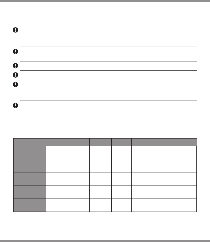
The allowable AC input voltage is 100~240V AC.
· 06 D100 V2
Standard Battery Parameters
3.7V/cell
Nominal
Voltage
Min. Discharge
Voltage
Max Charge
Voltage
Storage
Voltage
Allowable
Fast Charge
3.7V/cell
4.2V/cell
3.8V/cell
≦1C
LiPo LiIon
3.6V/cell
4.1V/cell
≦1C
3.3V/cell
3.6V/cell
3.3V/cell
≦4C
LiFe
3.0-3.3V/cell 2.9-3.2V/cell 2.6-2.9V/cell
1.2V/cell
1.5V/cell
n/a
1C-2C
NiCd
1.2V/cell
1.5V/cell
n/a
1C-2C
NiMH
2.0V/cell
2.46V/cell
n/a
≦0.4C
Pb
0.1-1.1V/cell 0.1-1.1V/cell
1.8V/cell
LiHV
3.8V/cell
4.35V/cell
3.85V/cell
≦1C
3.1-3.4V/cell

A battery pack which consists of different types of cells (including different
manufacturers)
A battery that is already fully charged or just slightly discharged.
Non-rechargeable batteries (Explosion hazard).
Batteries that require a different charge technique from NiCd, NiMh, LiPo or Gel cell
(Pb, Lead acid).
A faulty or damaged battery.
A battery fitted with an integral charge circuit or a protection circuit.
Batteries installed in a device or which are electrically linked to other components.
Batteries that are not expressly stated by the manufacturer to be suitable for the
currents the charger delivers during the charge process.
Please bear in mind the following points before commencing charging:
Did you select the appropriate program suitable for the type of battery you are
charging?
Did you set up adequate current for charging or discharging?
Have you checked the battery voltage? Lithium battery packs can be wired in parallel
and in series, i.e. a 2 cell pack can be 3.7V (in parallel) or 7.4V (in series).
Have you checked that all connections are firm and secure?
Make sure there are no intermittent contacts at any point in the circuit.
Charging
During charge process, a specific quantity of electrical energy is fed into the battery.
The charge quantity is calculated by multiplying charge current by charge time. The
maximum permissible charge current varies depending on the battery type or its
performance, and can be found in the information by the battery manufacturer. Only
batteries that are expressly stated to be capable of quick-charge are allowed to be
charged at rates higher than the standard charge current.
Connect the battery to the terminal of the charger: red is positive and black is
negative. Due to the difference between resistance of cable and connector, the
charger can not detect resistance of the battery pack, the essential requirement
for the charger to work properly is that the charge lead should be of adequate
conductor cross-section, and high quality connectors which are normally gold-
plated should be fitted to both ends.
Always refer to the manual by battery manufacturer about charging methods,
recommended charging current and charging time. Especially, the lithium battery
should be charged according the charging instruction provided by the manufacturer
strictly.
Never attempt to charge or discharge the following types of batteries.
Warning And Safety Notes
07 ·
D100 V2

Discharging
The main purpose of discharging is to clean residual capacity of the battery, or to
reduce the battery voltage to a defined level. The same attention should be paid to
the discharging process as charging. The final discharge voltage should be set up
correctly to avoid deep-discharging. Lithium battery can not be discharged to lower
than the minimum voltage, or it will cause a rapid loss of capacity or a total failure.
Generally, lithium battery doesn't need to be discharged. Please pay attention to the
minimum voltage of lithium battery to protect the battery.
Some rechargeable batteries have a memory effect. If they are partly used and
recharged before the whole charge is accomplished, they remember this and will only
use that part of their capacity next time. This is a memory effect. It is said that NiCd
and NiMH batteries are suffering from memory effect. NiCd has more memory effect
than NiMH.
Attention should be paid to the connection of lithium battery especially.
Do not attempt to disassemble the battery pack arbitrarily.
Please get highlighted that lithium battery packs can be wired in parallel and in series.
In the parallel connection, the battery’s capacity is calculated by multiplying single
battery capacity by the number of cells with total voltage stay the same. The voltages
imbalance may cause fire or explosion .Lithium battery is recommended to charge in
series.
Warning And Safety Notes
· 08 D100 V2
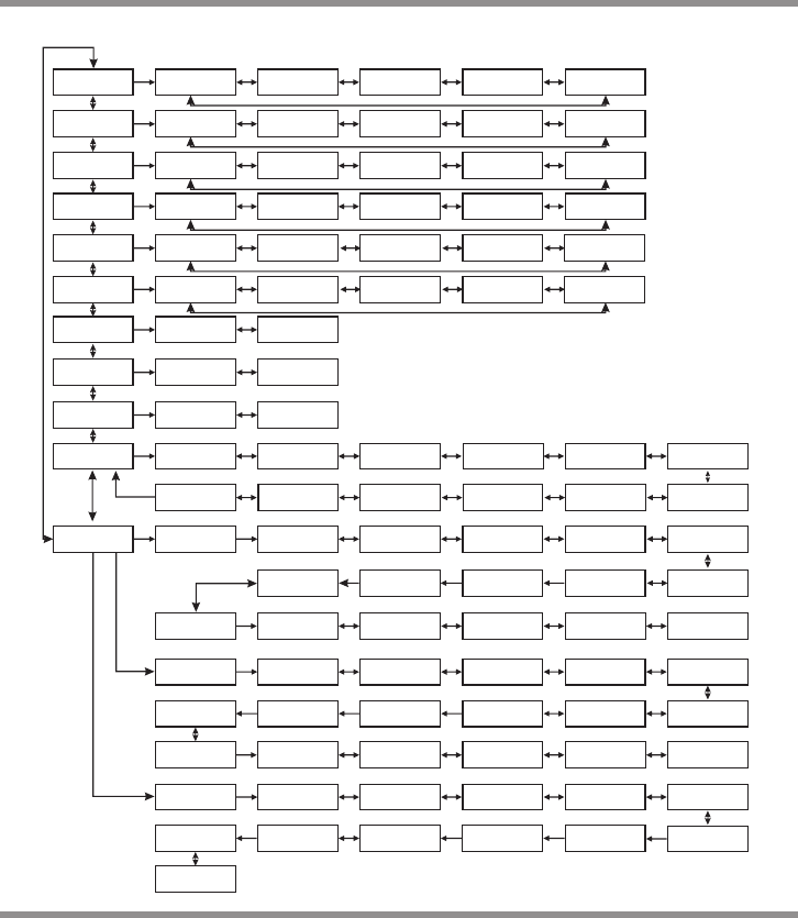
Program Flow Chart
BATT/PROGRAM
Pb BATT
ENTER
START
Pb CHARGE
2.0A 2.0V (1P) DEC
INC Pb DISCHARGE
0.1A 2.0V (1P)
BATT/PROGRAM
NiCd BATT
NiCd CHARGE
CURRENT 2.0A
ENTER
START
DEC
INC NiCd DISCHARGE
0.1A CUT: 1.0V DEC
INC NiCd CYCLE
CHG>DCHG 1
BATT/PROGRAM
NiMH BATT
ENTER
START
NiMH CHARGE
CURRENT 2.0A DEC
INC NiMH DISCHARGE
0.1A CUT: 1.0V
NiMH CYCLE
CHG>DCHG 1
DEC
INC
BATT/PROGRAM
LiPo BATT
LiPo BALANCE
2.0A 7.4V (2S)
LiPo CHARGE
2.0A 7.4V (2S)
LiPo FAST CHG
2.0A 7.4V (2S)
LiPo STORAGE
2.0A 7.4V (2S)
LiPo DISCHARGE
2.0A 7.4V (2S)
ENTER
START
DEC
INC
DEC
INC
DEC
INC
DEC
INC
DECINC
DECINC
BATT/PROGRAM
LiFe BATT
Lilo BALANCE
2.0A 7.2V (2S)
Lilo CHARGE
2.0A 7.2V (2S)
Lilo FAST CHG
2.0A 7.2V (2S)
Lilo STORAGE
2.0A 7.2V (2S)
Lilo DISCHARGE
2.0A 7.2V (2S)
ENTER
START
DEC
INC
DEC
INC
DEC
INC
DEC
INC
BATT/PROGRAM
LiIo BATT
LiFe BALANCE
2.0A 6.6V (2S)
LiFe CHARGE
2.0A 6.6V (2S)
LiFe FAST CHG
2.0A 6.6V (2S)
LiFe STORAGE
2.0A 6.6V (2S)
LiFe DISCHARGE
2.0A 6.6V (2S)
ENTER
START
DEC
INC
DEC
INC
DEC
INC
DEC
INC
DECINC
BATT/PROGRAM
BATT METER
4.20 4.19 4.19 V
0.00 0.00 0.00 V
MAIN 0.00V
H0.000V L0.000V
DEC
INC
DECINC
DECINC
DEC
INC
NiCd RE-PEAK
1
DEC
INC
NiMH RE-PEAK
1
DEC
INC
NiMH Auto CHARGE
CURRENT 2.0A
DEC
INC
NiCd Auto CHARGE
CURRENT 2.0A
DECINC
DECINC
DECINC
LiHV BALANCE
2.0A 7.6V (2S)
LiHV CHARGE
2.0A 7.6V (2S)
LiHV FAST CHG
2.0A 7.6V (2S)
LiHV STORAGE
2.0A 7.6V (2S)
LiHV DISCHARGE
2.0A 7.6V (2S)
BATT/PROGRAM
LiHV BATT
ENTER
START
DEC
INC
DEC
INC
DEC
INC
DEC
INC
DECINC
Note: The flow chart is taking one channel for example as the flow chart for the two channels (Channel A and
Channel B) are identical.
BATT/PROGRAM
BATT MEMORY
ENTER
START
[ BATT MEMORY 1 ]
ENTER SET->
ENTER
START
BATT TYPE
LiPo DEC
INC BATT VOLTAGE
7.4V ( 2S ) DEC
INC CHARGE CURRENT
4.9A DEC
INC DISCHG CURRENT
2.2A
DISCHG VOLTAGE
3.0V/CELL
TVC=YOUR RISK !
4.20V
DEC
INC
ENTER
START
ENTER
START
BATT/PROGRAM
SYSTEM SETTING->
ENTER
START
Stop
Batt Type
DECINC
SAVE PROGRAM
ENTER
SAVE PROGRAM
SAVE….
[ BATT MEMORY 1 ]
LiPo 7.4V (2S )
[ BATT MEMORY 1 ]
C:4.9A D:2.2A
ENTER CHARGER
LOAD……
LiPo BALANCE CHG
4.9A 7.4V(2S)
LiPo CHARGE
4.9A 7.4V(2S)
DEC
INC LiPo FAST CHARGE
4.9A 7.4V(2S)
DEC
INC LiPo STORAGE
4.9A 7.4V(2S)
LiPo DISCHARGE
2.2A 7.4V(2S)
DEC
INC
DEC
INC
BATT TYPE
MiMH DEC
INC BATT VOLTS
2.4V (2S)
ENTER
START
CHARGE CURRENT
3.3A
DEC
INC
DEC
INC TRICKLE
100mA DEC
INC PEAK DELAY
1Min
DECINC
DSCH CURRENT
2.2A
DEC
INC DSCH VOLTAGE
1.1V/CELL
SAVE PROGRAM
ENTER
ENTER
START
BATT TYPE
Pb
BATT VOLTS
4.0V (2P)
DEC
INC CHARGE CURRENT
3.3A
DEC
INC DSCH CURRENT
1.5A
DEC
INC DSCH VOLTAGE
1.7V/CELL
DEC
INC
SAVE PROGRAM
ENTER
DECINC
DEC
INC
DEC
INC
DECINC
BATT/PROGRAM
BATT RESISTANCE
DECINC
ENTER
START
005 003 003 mΩ
005 mΩDEC
INC TATAL: 16mΩ
H: 5mΩ L: 3mΩ
ENTER
START
STARG/ENTER>3Seconds
SAVE PROGRAM
SAVE….
ENTER
START
[ BATT MEMORY 2 ]
NiMH 2.4V (2S )
[ BATT MEMORY 2 ]
C:1.0A D:1.0A
STARG/ENTER>3s
ENTER CHARGER
LOAD……
NiMH CHARGE
CURRENT 1.0A
NiMH Auto CHARGE
CURRENT 1.2A
DEC
INC
DEC
INC
DEC
INC
DEC
INC
NiMH DISCHARGE
1.0A CUT: 2.0V
NiMH RE-PEAK
2
NiMH CYCLE
DCHG>CHG 1
[ BATT MEMORY 2 ]
ENTER SET->
[ BATT MEMORY 3 ]
ENTER SET->
SAVE PROGRAM
SAVE….
ENTER
START
[ BATT MEMORY 3 ]
Pb 4.0V (2S )
[ BATT MEMORY 3 ]
C:3.3A D:1.5A
ENTER CHARGER
LOAD……
Pb CHARGE
3.3A 4.0V(2P)
Pb DISCHARGE
1.5A 4.0V(2P)
DECINC
Version
HW:1.00 FW: 2.00
Load Factory Set
Enter DEC
INC
DEC
INC
Rest Time
CHG>DCHG 10Min
DEC
INC
Safety Timer
ON 120Min DEC
INC
Capacity Cut-Off
ON 5000mAH DEC
INC
DEC
INC
Temp Cut-Off
ON 50°C 122°F
Temperature Unit
Celsius
NiCd Sensitivity
D.Peak 4mV
Key Beep ON
Voice ON
DEC
INC
DC Input Low
CUT-OFF 11.0V DEC
INC
ENTER
START
09 ·
D100 V2
START ENTER > 3s
NiMH Sensitivity
D.Peak 4mV
DEC
INC
DEC
INC
DC SUPPLY: OFF
CH1: 50 CH2:50W

Operation
When you are willing to alter the parameter value in the program, press the
START/ENTER button to make it blink then change the value by pressing DEC and INC
button. The value will be stored by re-pressing the START/ENTER button. If there is
another parameter can be altered in the same screen, when you confirm the first
parameter value, the next parameter value will start to blink which means it is ready to
alert.
When you are willing to start the process, press and hold the START/ENTER button for 3
seconds. When you are willing to stop the progress or go back to previous step/screen,
press the BATT PROG/STOP button once.
When you power on the charger, it will enter LiPo Battery balance program directly. You
could change the mode (balance mode, normal charge mode, fast charge mode, storage
mode or discharge mode), enter the desired charging/discharging mode, set the referred
parameter and start the progress.
If you have no request for LiPo Battery program, please press the BATT PROG/STOP
button to enter BATT PROGRAM screen.
CH A/CH B
It is used to switch from Channel A to B or Channel B to A.
BATT PROG / STOP Button:
It is used to stop the progress or go back to previous step/screen
DEC Button:
It is used to go through the menus and decrease the parameter value
INC Button:
It is used to go through the menus and increase the parameter value
ENTER / START Button:
It is used to enter parameter or store parameter on screen.
· 10 D100 V2
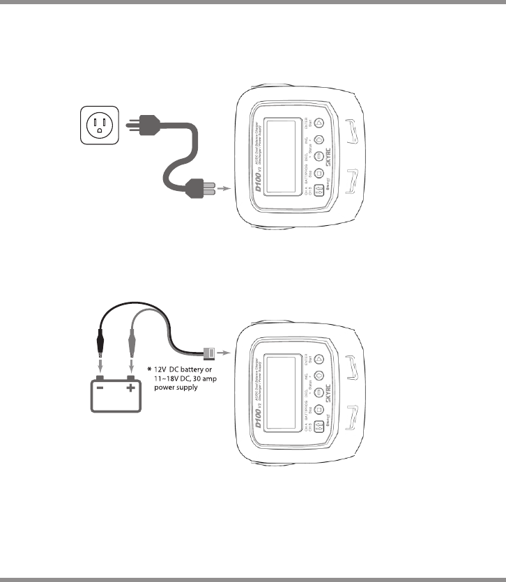
Power and Battery Connection
1. Connecting to power source
There are two kinds of inputs for SKYRC D100 V2, DC 11-18V and AC 100-240V.
12V DC Battery / DC power supply connection.
AC 100-240V power source connection.
11 ·
XT60
D100 V2
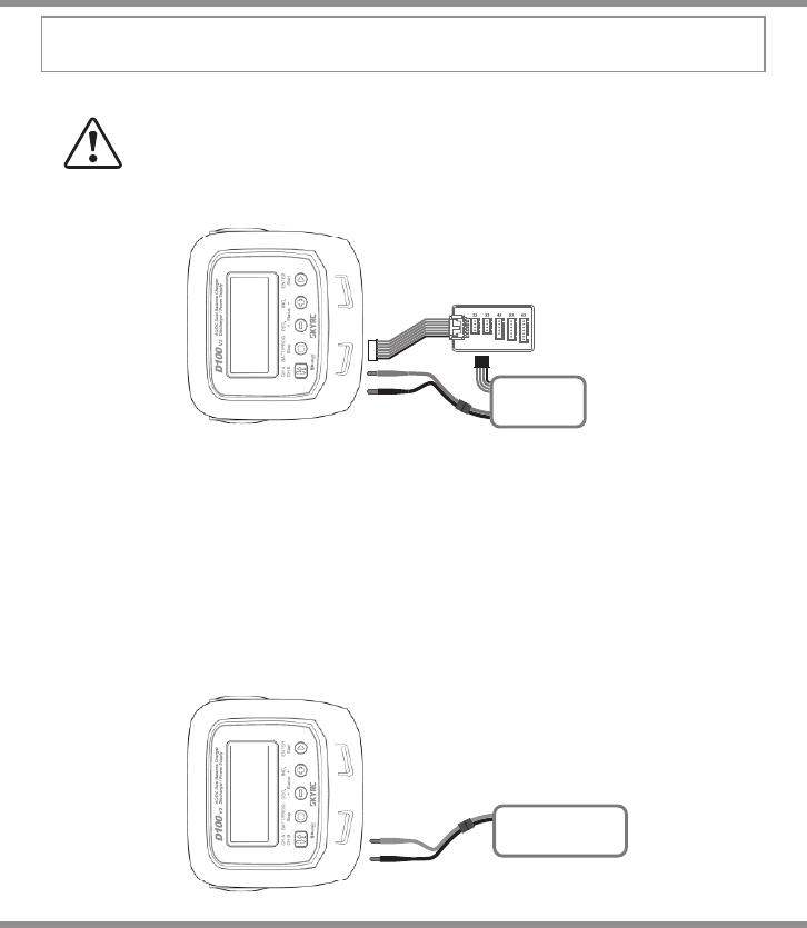
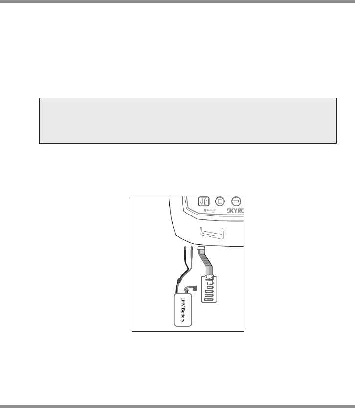
1) LiPo Battery Connection with Balance Adapter
2) NiMH/NiCd or Pb Battery Connection
TO AVOID SHORT CIRCUITS, ALWAYS CONNECT THE CHARGE LEADS
TO THE CHARGER FIRST, AND THEN TO THE BATTERY. REVERSE THE
SEQUENCE WHEN DISCONNECTING THE PACK.
WARNING!
2. Connecting the battery
Balance Socket
The balance wire attached to the battery must be connected to the charger with the
black wire aligned with the negative marking. Ensure correct polarity!
For safety reasons, the default setting for charging Lithium (LiPo, Lilon, LiFe and LiHV)
battery is using balance adaptor to connect battery and charger in Charge, Fast Charge,
Balance Charge, Discharge and Storage modes. But if the battery comes without balance
wire,please proceed with the prompting message "No balance cable detected, push
enter to continue".
Note: We will explain the operating procedure of one channel as the procedure for
channel A and B is identical.
Power and Battery Connection
· 12
LiPo
NiMH
D100 V2
Operating Program
Here is the detailed procedure to make the charger work. All the screens and operations
will take Li-Po BALANCE CHARGE program for example,
Note: We will explain the operating procedure of one channel as
the procedure for channel A and B is identical..
1. Connection
Connecting to power source
There are two kinds of inputs for SKYRC D100 V2, DC 11-18V and AC 100-240V.
A. Operating in AC mode
SKYRC D100 V2 comes with built-in switching power supply. You can connect the
AC power cord directly to the main AC socket. (100-240V AC).
Note: The output power in AC mode is 100W totally for Channel A, Channel B and
Power supply.
In AC mode, it supports Power Distribution. The total power for Channel A, Channel
B and power supply is 100W. You could set the Max Power for one output port
(Take Channel A for example)as following,
Then, the channel B and DC power supply will take the rest power automatically (For
example, if you set DC power supply as 20W and Channel A as 50W, the Channel B will
take the rest power of 30W.
If Channel A/Channel B and DC power supply are both working, you can't
change the power for them.
If DC power supply is working, you can change the power of Channel A and
Channel B. thus, the DC power supply will take the rest power automatically.
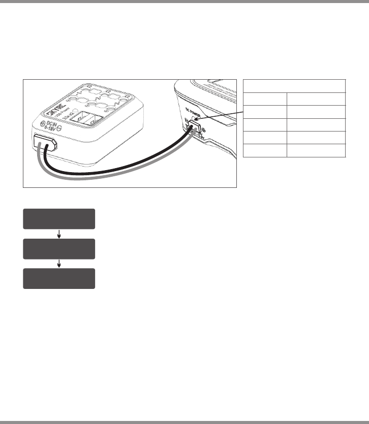
B. Operating in DC mode
Please connect SKYRC D100 V2 with AC/DC power supply by supplied DC input cable.
Also you could use terminal clips with DC connectors, for attaching directly to 12V car
batteries. It is critically important that you use either a fully charged 13.8V car battery or a
high-quality AC/DC power supply in the range of 11-18V DC output with minimum power
300W or higher to insure reliable performance.
1).
NOTE1:
NOTE2:
13 ·
D100 V2
A
B
DC SUPPLY: 20W
CHA:50W CHB:30W
DC SUPPLY: 20W
CHA:50W CHB:30W
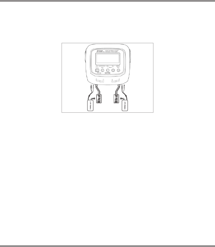
Failure to connect as shown in this diagram will damage this charger.
To avoid short circuit between the charge lead always connect the charge cable to the
charger first, then connect the battery. Reverse the sequence when disconnecting.
WARNING:
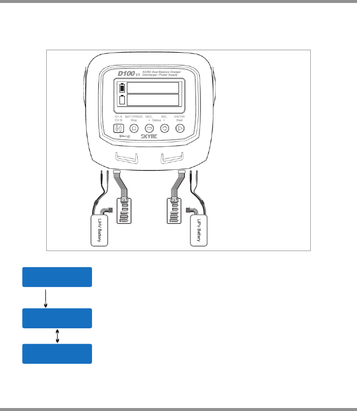
Connecting the battery
Important!!! Before connecting a battery it is absolutely essential to check one last
time that you have set the parameters correctly. If the settings are incorrect, the
battery may be damaged, and could even burst into flames or explode. To avoid
short circuits between the banana plugs, always connect the charge leads to the
charger first, and only then to the battery. Reverse the sequence when
disconnecting the pack.
Balance Socket
The balance wire attached to the battery must be connected to the charger with the
black wire aligned with the negative marking. Take care to maintain correct polarity!
(See the wiring diagram below.)
This diagram shows the correct way to connect your battery to the SKYRC D100
V2 while charging.
2).
3).
Operating Program
It is a MUST for charging Lithium (LiPo, Lilon, LiFe and LiHV) battery in
Charge, Fast Charge, Balance Charge and Storage mode. If you don't connect
the battery to the balance socket while the charger is working in mentioned
modes, the charger won't start working.
· 14 D100 V2
The following flowcharts show the entire programming menu. It is highly recommended to
keep these flowcharts handy while you learn how to operate this charger.
There are two main ways to program the charger.
A memory profile is available for setting and storing pertinent information for up to
20 different program sets; each channel can store 10 sets. Once a battery program
is stored into memory, it will be retained until changed again manually. Recalling a
program memory number makes the charger instantly ready to go!
If you do not wish to use the battery program memories, this charger can be
manually set before each use.
(1)
(2)
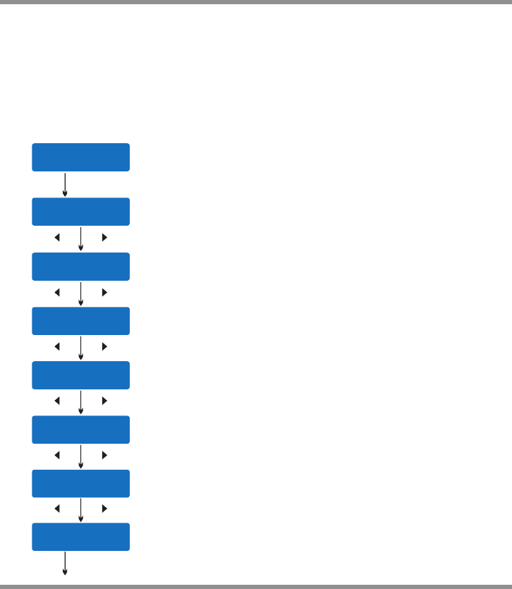
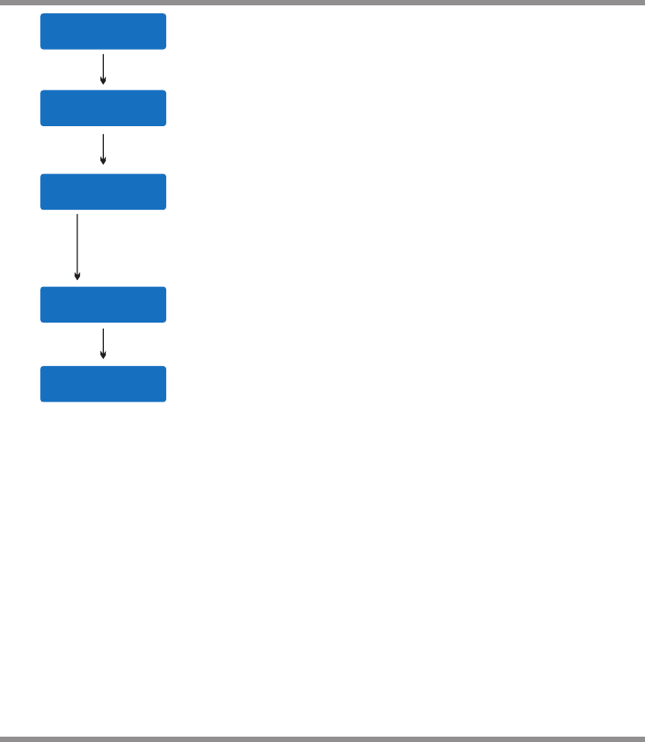
The following flowchart shows how the program is set manually:
BATT/PROGRAM
LiPo BATT
LiPo BALANCE
2.0A 11.1V (3S)
LiPo BALANCE
2.0A 11.1V (3S)
LiPo BALANCE
2.0A 11.1V (3S)
LiPo BALANCE
2.0A 11.1V (3S)
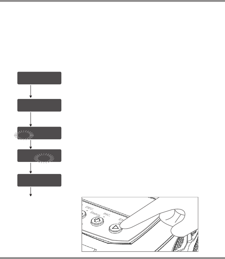
BATT/PROGRAM Select
Mode Select
Program Start
Press INC and DEC to go through all the programs and press
START/ENTER to enter LiPo BATT Program.
Battery Setting
Press INC and DEC to go through all the modes and press
START/ENTER to enter LiPo Balance Charge Mode.
Press START/ENTER, the present value will start to blink. Press
INC and DEC to change the value and press START/ENTER to
confirm your setting.
At the same time, the battery pack’s cell count will start to blink,
press INC and DEC to change the value and press START/
ENTER to confirm your setting.
Press and hold START/ENTER for 3 seconds to start the
program.
START/ENTER
START/ENTER
START/ENTER
START/ENTER
START/ENTER
> 3 Seconds
Lithium Battery Program (LiPo/LiFe/Lilon/LiHV)
15 ·
D100 V2
R:3SER S:3SER
CONFIRM(ENTER)
Lp3s 1.5A 12.14V
BAL 000:50 00022
START/ENTER
R shows the number of cells detected by the charger and S is the number
of cells set by you on the previous screen. If the two numbers are identical,
press START/ENTER to start the charging process.
Charging Status Monitor
During charge process, real-time status will be shown as seen on the left.
Program Stop
During the charging process, press STOP to stop the charging process.
Program Complete
Lithium Battery Program(LiPo/LiFe/Lilon/LiHV)
BATTERY CHECK
WAIT... The charger is detecting the battery cell.
R shows the number of cells detected by the charger and S is
the number of cells set by you on the previous screen. If the
two numbers are not identical, press STOP to go back to the
previous screen to recheck the number of cells of the battery
pack that you set before going ahead.
R:3SER S:3SER
CANCEL(STOP)
[ END: FINISH ]
16.8V 2600mAh
[ Time: 00: 45: 32 ]
16.8V 2600mAh
Once the battery is fully charged, the screen will read “END:
FINISH” and the charger will emit a ringing sound. The charger
also displays battery voltage, charged capacity and elapsed time.
· 16 D100 V2
Lithium Battery Program (LiPo/LiFe/Lilon/LiHV)
VARIOUS INFORMATION DURING THE PROCESS
Press INC or DEC during the charging or discharging process to view further pertinent information on
the LCD screen.
Lp3s 1.5A 12.14V
BAL 000:50 00022
4.07 4.06 4.11 V
0.00 0.00 0.00 V
Fuel= 90%
Cell= 4.10V
INC
INC
Lp3s 1.5A 12.14V
BAL 000:50 00022
Ext. Temp ----
Int. Temp 37°C
DEC
Temp Cut-Off
50C
DEC
Final voltage when the program ends.
Input voltage.
Safety timer ON and duration of time in minutes.
Capacity cut-off ON and value of the set capacity limit.
Voltage of each cell in the battery pack when the battery is connected
with balance lead.
Internal temperature.
Temperature probe needs to be connected to show external temperature.
Charged capacity percentage and average cell voltage of the battery
pack.
Real-time status: battery type, battery cell count, charge current, battery
pack total voltage,working mode, elapsed time and charged capacity.
Cut-off temperature.
DEC
DEC
DEC
DEC
End Voltage
12.6V(3S)
IN Power Voltage
12.56V
Safety Timer
ON 200min
Capacity Cut-Off
ON 5000mAh
17 ·
D100 V2
NiMH/NiCd Battery Program
NiMH CHARGE
CURRENT 2.0A
Press the ENTER button and the amp rate value will begin blinking.
Use the DEC or INC button to adjust the value to the desired rate.
Follow the instructions provided on your battery when setting the
charge current.
Press and hold the ENTER button for 3 seconds to start charging.
Once charging has commenced, the charger will display the
following real-time information: battery type, charging current, battery
voltage, working mode, elapsed time and charged capacity. Once
the battery is fully charged, the screen will read "END: FINISHED"
and the charger will emit a ringing sound. You can press the STOP
button at any time during the charging process to stop charging.
NiMH 2.0A 5.42V
CHG 002:22 00106
NiMH/NiCd:
This program is only suitable for charging/discharging NiMH/NiCd batteries. The D100 V2 offers
the following NiMH/NiCd charge modes: Charge, Auto Charge, Discharge, Re-Peak and Cycle.
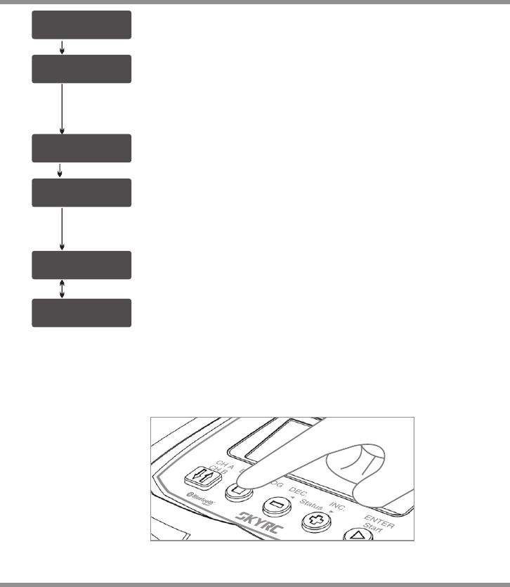
Selecting the Battery Type:
After powering on the D100 V2, press the INC or DEC button repeatedly until you reach the
appropriate program for the battery type you wish to charge. For this example we have chosen
the “NiMH BATT“ or “NiCd BATT” program. Now press the ENTER button to enter the desired
program.
NiMH/NiCd Charge Mode:
BEFORE YOU BEGIN CHARGING YOUR BATTERY, MAKE SURE YOU HAVE READ AND
UNDERSTOOD ALL OF THE WARNINGS AND SAFETY INFORMATION CONTAINED ON
PAGES 06-08.
After selecting the correct battery type, if the screen does not read “CHARGE”, use the DEC or
INC buttons to change it to the “CHARGE” mode.
NiMH/NiCd Auto Charge Mode:
In this mode, the charger automatically detects the connected NiMH or NiCD battery and
determines the proper full charge and cut-off thresholds. Setting the upper charge current limit
for safe levels based on your battery specifications will ensure safe charging of your specific
battery. If you are unsure of the maximum allowable charge rates, set the charger to a
maximum of 1C (battery mAh/1000, e.g. 3200mAh = 3.2A).
BEFORE YOU BEGIN CHARGING YOUR BATTERY, MAKE SURE YOU ARE
CHARGING NIMH/NICD BATTERIES. CHARGING LIPO BATTERY UNDER NIMH/
NICD BATTERY PROGRAM WILL CAUSE FIRE.
WARNING!
· 18
START/ENTER
D100 V2
NiMH/NiCd Battery Program
After selecting the correct battery type, use the INC or DEC
button to change the charge mode to the “Auto CHARGE”
setting.
Press the START button and the amp rate value will begin
flashing. Use the INC or DEC button to adjust the value to the
desired rate. Follow the instructions provided on your battery
when setting the upper charge amperage rate.
Press and hold the START button for 3 seconds to start charging.
Once charging has commenced, the charger will display the
following real-time information: battery type, charging current,
battery voltage, elapsed time and charged capacity.
Once the battery is fully charged, the screen will read “END:
FINISHED” and the charger will emit a ringing sound. You can
press the STOP button at any time during the charging process
to stop charging.
NiMH/NiCd Discharge Mode:
After selecting the correct battery type, use the INC or DEC
button to select the “DISCHARGE” mode. Press the START
button and the amp rate value will begin flashing. Use the INC
or DEC buttons to adjust the value to the desired discharge rate.
Press the START button again and the voltage cut-off will begin
to flash. Use the INC or DEC button to adjust the value to the
desired rate.
NiMH Auto CHARGE
CURRENT 1.3A
NiMH 1.3A 5.42V
AUT 002:22 00106
NiMH DISCHARGE
1.3A CUT:9.6V
Follow the instructions provided on your battery when setting the
voltage cut-off. The D100 V2 will stop discharging when the
battery has reached the preset voltage cut-off.
Press and hold the START button for 3 seconds to start discharging.
Once discharging has commenced, the charger will display the
following real-time information: battery type, discharging current,
battery voltage, working mode,elapsed time and discharged
capacity.
NiMH 1.3A 10.42V
AUT 002:22 00106
19 ·
START/ENTER
D100 V2

NiMH/NiCd Battery Program
When discharging is complete, the screen will read “END:
CUTOFF-VOL” and the charger will emit a ringing sound.
The charger will display the elapsed time, end voltage and the
discharged capacity in mAh.
You can press the STOP button at any time during the
discharging process to stop the discharge process.
NiMH/NiCd Re-Peak Mode:
Applicable to NiMH and NiCD batteries only, in re-peak mode the charger can peak-
charge the battery once, twice, or three times in a row automatically. This process is good
for confirming that the battery is fully charged and for verifying how well the battery can
accept a fast charge. A five-minute cool-down delay occurs after each re-peak charge.
IN RE-PEAK MODE, THE D100 V2 USES THE CHARGE AMPERAGE AND VOLTAGE
SETTINGS ENTERED IN CHARGE MODE.
After selecting the correct battery type, use the INC or DEC
button to select the “RE-PEAK” mode. Press the START button
and the Re-peak cycle number 1 begins to flash on the screen.
Use the INC or DEC button to scroll through the cycle count and
set a number between 1 and 3.
Press and hold the START button for 3 seconds to start the re-
peak process.
[ TIME: 00:04:04 ]
9.6V 00640mAh
NiMH RE-PEAK
2
Once the Re-Peak process has begun, the charger will display
the following real-time information: battery type, charging
current, battery voltage, elapsed time and charged capacity.
Once the Re-Peak process has completed, the screen will read
“END: RE-PEAK” and the charger will emit a ringing sound. The
charger will display the charge/discharge capacity for each
cycle. Using the + and - buttons, you can scroll through the
history data of each cycle.
NiMH 1.3A 10.42V
RPC 004:04 00686
· 20
START/ENTER
D100 V2

NiMH/NiCd Battery Program
NiMH/NiCd Cycle Mode:
The D100 V2 makes cycling of NiMH/NiCd batteries easy. The process of discharging
and recharging (cycling) can be performed automatically with one simple step and will
improve the performance of NiMH/NiCd batteries. We strongly recommend cycling any
battery that has been discharged and stored for a period of time. This will increase the
remaining usable battery life and also improve the battery performance.
After selecting the correct battery type, use the INC or DEC
button to select the “CYCLE” mode. The Cycle Mode gives you
two cycling options: “DCHG>CHG” or “CHG>DCHG“. The
“DCHG>CHG” option will first discharge the battery and then
recharge the battery.
The “CHG>DCHG” option will first charge the battery and then
discharge the battery. If this screen does not show your desired
cycling option, press the START button once and this setting will
begin flashing. Use the INC or DEC button to change this
setting.
Pressing the START button again will cause the cycle count to
begin flashing. Use the INC or DEC button to change this to the
number of cycles you want the D100 V2 to run. The D100 V2
can cycle the battery a maximum of 5 times consecutively.
Press and hold the START button for 3 seconds to start the
Cycle Mode.
NiMH CYCLE
DCHG > CHG 2
NiMH CYCLE
CHG > DCHG 5
Once cycling has commenced, the charger will display the
following real-time information: battery type, charging/
discharging current, battery voltage, working mode,elapsed time
and charged/discharged capacity. You will also see “D>C“ or
“C>D“. This will indicate which cycling order you have chosen.
Either “D“ or “C“ will be flashing. This flashing indicates which
part of the cycle is currently being executed.
NiMH 0.5A 9.6V
D > C 004:04 00034
Once the cycling process is complete, the screen will read “END: CYCLE” and the
charger will emit a ringing sound. The D100 V2 will display the charged/discharged
capacity for each cycle. Using the + and - buttons, you can scroll through this data for
each cycle.
21 ·
START/ENTER
D100 V2

Pb Lead-Acid Battery Program
Additional NiMH/NiCd Process Information:
During the NiMH/NiCd battery charging/discharging process the D100 V2 can display a
variety of information. Using the INC or DEC buttons, you can also view the following
information:
NiMH Sensitivity
D.Peak 4mV/CELL
Ext. Temp ----
Int. Temp 37 C
Safety Timer
ON 200min
In Power Voltage
12.56V
Temp Cut-off
50 C/122 F
Capacity Cut-Off
ON 5000mAh
Delta Peak Voltage
Sensitivity setting
External*/ internal
temperature
Safety timer
setting
Input Voltage
Temperature
cut-off
Capacity limit
setting
Pb Lead-Acid Battery Program
This program is only suitable for charging Pb (lead-acid)
batteries with nominal voltage ranging from 2 to 24V. Pb (lead-
acid) batteries are significantly different from NiMH/NiCd
batteries. Pb batteries can only deliver a low current in relation
to their capacity. The same restriction applies to the charging
process. Consequently, the optimum charge current can only be
1/10th of the capacity. A Pb battery cannot be used for fast
charging. Please follow the instructions provided by the battery
manufacturer.
The D100 V2 offers the following Pb charge modes: Charge and
Discharge.
Pb (Lead-Acid):
BATT/PROGRAM
Pb BATT
Pb Charge Mode:
After selecting the correct battery type, use the INC or DEC button to change it to the
“CHARGE“ mode.
Press the START button and the amp rate value will begin flashing. Use the INC or DEC
buttons to adjust the value to the desired charge rate. The amp rate should be set to
1/10th of capacity. For example, if you are charging a 20Ah battery the charge rate should
be set to 2A. Follow the instructions provided on your battery when setting the amp rate.
· 22 D100 V2

Pb Lead-Acid Battery Program
Press the START button again and the nominal battery pack
voltage will begin flashing. Use the INC or DEC button to set the
voltage and the number of cells.
Press and hold the START button for 3 seconds to start
charging.
Once charging has commenced, the charger will display the
following real-time information: battery type, charging current,
battery voltage, working mode, elapsed time and charged
capacity.
When charging is complete, the screen will read “FINISHED”
and the charger will emit a ringing sound.
Pb Discharge Mode:
After selecting the correct battery type, use the INC or DEC buttons to change it to the
“DISCHARGE“ mode.
Press the START button and the amp rate value will begin flashing. Use the INC or DEC
buttons to adjust the value to the desired discharge rate. Follow the instructions provided
with your battery when setting the amp rate.
Pb Charge
1.5A 12.0V(6P)
P-6 1.5A 13.56V
CHG 002:22 00106
Press the START button again and the nominal battery pack
voltage will begin flashing. Use the INC or DEC buttons to set
the voltage and the number of cells.
Press and hold the START button and discharging will begin.
Once discharging has commenced, the charger will display the
following real-time information: battery type, cell count,discharging
current, battery voltage, elapsed time and discharged capacity.
When discharging is complete, the screen will read “FINISHED”
and the charger will emit a ringing sound.
Additional Pb Process Information:
During the Pb battery charging/discharging process the D100 V2 can display a variety of
information. Using the INC or DEC buttons you can also view the following information:
Pb Discharge
1.5A 12.0V(6P)
P-6 1.0A 13.56V
DCH 005:10 00964
Capacity Cut-Off
ON 5000mAh
Temp Cut-off
50 C
In Power Voltage
12.56V
Safety Timer
ON 200min
Ext. Temp ----
Int. Temp 37 C
Capacity cut-
off setting
Temperature
cut-off
Input voltage
Safety timer
setting
External*/ internal
temperature
23 ·
D100 V2
· 24
DC Power Supply
Operating Instruction
BATT/PROGRAM
SYSTEM SETTING->
DC SUPPLY: 20W
CHA: 50 CHB: 30W
ENTER
Press the ENTER to enter the DC Power Supply program
Set the output power for the DC charger or other devices. (please
note the voltage is 13.8V)
Set the power of channel A and channel B, the power supply will
take the rest power automatically.
Caution: The maximum DC Power output is 100 Watts and the maximum current is 10A.
Please check the total loading of your equipments before using DC power supply.
If the loading of DC power supply is over 100W, the led light will flash red.
ENTER
CH1: 50 CH2: 50W
DC SUPPLY: 150W
D100 V2
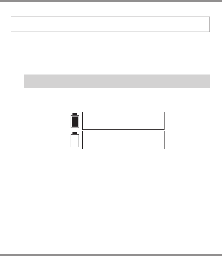
To use D100 V2 as a power supply, the user must connect it to AC power source. When
the green LED on the back side turns on, then the user is free to use the power supply,
the power of DC output is adjustable from 10W to 100W. The output voltage is 13.8V. The
power of DC output is shared with charger power. When you increase the power of DC
output, the charger power will be decreased accordingly. (DC Power + Channel
A+Channel B Power = 100 Watts)
OFF
Green
Yellow
Red
Red Blinking
DC Power Off
0-30% Loading
31-60% Loading
61-100% Loading
Over Load
EXPLANATION OF LED STATUS
Battery Memory Set and Call Out
[ B ATT M E MOR Y 1 ]
E NT E R S ET- >
B ATT T Y PE
L i P o
B ATT V O LTA G E
7 .4 V ( 2 S )
C HAR G E CUR R E NT
2 .0 A
D ISC H G CUR R E NT
2 .0 A
D ISC H G VOL T A GE
3 .0 V / CEL L
T VC= Y OUR R I S K!
4 .2 0 V
S AVE P R OGR A M
E NT E R
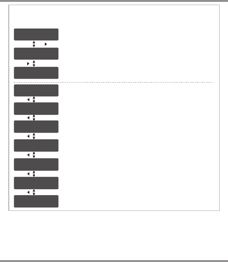
The charger can store up to 20 different charge/discharge profiles(each channel 10 sets)
for your convenience, and the stored profiles can be recalled quickly without having to go
through the setup process.
When you are willing to alter the parameter value in the program, press START/ENTER to
make it blink then change the value with INC or DEC. The value will be stored by
pressing START/ENTER once.
Note: All following screen are taking 2S(7.4V) LiPo battery for example.
Enter the battery memory program.
(10 different charge/discharge profiles can be stored in each channel).
Set the battery type(LiPo/LiFe/LiIon/LiHV/NiMH/NiCd/Pb).
Set the voltage and number of cells(1S-6S).
Set the charge current(0.1-10.0A).
Set the discharge current (0.1A-2.0A).
Set the discharge voltage(3.0-3.3V/Cell).
Set the terminal voltage(4.18-4.25V).
Press ENTER to save program.
1. Battery Memory Set
START/ENTER
DEC INC
DEC INC
DEC INC
DEC INC
DEC INC
DEC INC
START/ENTER
25 ·
D100 V2
Battery Memory Set and Call Out
E NTE R C H ARG E R
L O A D
L iPo B A L ANC E C H G
4 .9A 7 . 4 V(2 S )
S AVE P R O GRA M
S A V E .
[ B ATT M E M ORY 1 ]
L iPo 7 . 4 V (2S )
[ B ATT M E M ORY 1 ]
C :4. 9 A D :2. 2 A
Indicate the battery type and battery cell of the saved profile.
Indicate the charge and discharge current of the saved profile.
Press the START/ENTER for 3 seconds to call out the memory.
2. Battery Memory Call Out
Load the memory set
Press START/ENTER for 3 seconds to start the process.
START/ENTER
>3 Seconds
· 26 D100 V2

System Setting
S afe t y T ime r
O N 120 M i n
C apa c i ty Cu t - O ff
O N 500 0 m AH
T emp e r atu r e U n it
C els i u s
T emp C u t -Of f
O N 50 C 1 2 2 F
This program sets the maximum charge
capacity that will be supplied to the battery
during charge. If the delta peak voltage is
not detected nor the safety timer expired by
any reason, this feature will automatically
stop the process at the selected capacity
value.
When you start a charge process, the
integral safety timer automatically starts
running at the same time. This is
programmed to prevent overcharge the
battery if it proves to be faulty, or if the
termination circuit cannot detect the battery
full. The value for the safety timer should be
generous enough to allow a full charge of
the battery.
The battery's internal chemical reaction will
cause the temperature of the battery to
rise. If the temperature limit is reached, the
process will be terminated.
OFF/
ON
(100-50000 mAh)
It will be operated with the default value of the essential user settings when it is powered
on for the first time.The screen displays the following information in sequence and the
user can change the value of parameter on each screen.
When you are willing to alter the parameter value in the program, press START/ENTER to
make it blink then change the value with INC or DEC. The value will be stored by
pressing START/ENTER once.
ITEM SELECTION DESCRIPTION
OFF/
ON
(1-720 Min)
OFF/
ON
(20 C/68 F -
80 C/176 F)
Celsius
Fahrenheit
You can choose the temperature displayed
by Celsius or Fahrenheit as you like.
D C SUP P L Y :OF F
C H1: 5 0 C H2: 5 0 W
OFF/
10-100W
In AC mode, it supports Power Distribution.
The total power for Channel A / Channel B
and DC supply is 100W. You could set the
AC Max Power for one output.
27 ·
D100 V2

ITEM SELECTION DESCRIPTION
System Setting
N i M HSensitivity
D .Pe a k 4 mV
N i C dSensitivity
D .Pe a k 4 mV
Default: 4mV/Cell
3-15mV/Cell
K ey Be e p O N
V oic e O N OFF/ON
The beep sounds at every time touching
the buttons to confirm your action. The
beep or melody sounded at various times
during operation to alert different mode
changes.
D C Inp u t L ow
C ut- O f f 11. 0 V 10.0-12.0V
This program monitors the voltage of input
battery. If the voltage drops below the value
you set the operation forcibly terminated to
protect the input battery.
This program is for NiMH/NiCd battery only.
When the charger detects the delta peak
value reaches the value you set, the
charger will say the battery is fully charged.
L oad F a c tor y S e t
E nte r
Version
H W:1 . 0 0 FW: 2 . 0 0
Press ENTER to load factory default setting.
It indicates the hardware and firmware
version.
R est T i m e
C HG> D C HG 10 M i n 1-60Min A rest time allowing the battery to cool
down between charging/discharging cycle.
· 28 D100 V2
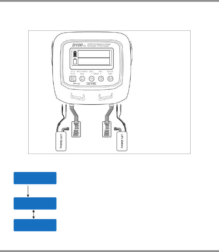
Battery Voltage Meter
The user can check battery's total voltage, the highest voltage, the lowest voltage and
each cell's voltage.
Please connect the battery to the charger main battery lead to battery socket and balance
wires to balance socket.
BATT/PROGRAM
B ATT M E T ER
4 .20 4 . 1 9 4.1 9 V
4 .18 4 . 1 8 4.1 9 V
M AIN 2 5 . 13V
H 4.2 0 0 V L4. 1 8 2 V
Press the START/ENTER to enter the Lithium
Battery Meter program.
The screen indicate each cell's voltage.
The screen indicate the total voltage, the highest
voltage and the lowest voltage.
START
ENTER
DEC
This diagram shows the
correct way to connect
your battery to check
the voltage.
INC
29 ·
D100 V2
A
B
4.19 4.15 4.18V
4.15 4.19 4.18V
4.19 4.15 4.18V
4.15 4.19 4.18V
Battery Resistance Meter
The user can check battery's total resistance, the highest resistance, the lowest
resistance and each cell's resistance.
Please connect the battery to the charger main battery lead to battery socket and balance
wires to balance socket.
Press the START/ENTER to enter the Lithium
Battery Resistance program.
The screen indicate each cell's resistance.
The screen indicate the total resistance, the highest
resistance and the lowest resistance.
Start
Enter
BATT/PROGRAM
B ATT R E S IST A N C E
0 12 00 5 0 0 5 mΩ
0 06 mΩ
T A T A L :28mΩ
H :1 2 mΩ L :5 mΩ
DEC
This diagram shows the
correct way to connect
your battery to check
the resistance.
INC
· 30 D100 V2
0 0 5 00 3 00 3 mΩ
0 0 5 00 3 00 3 mΩ
0 0 5 00 3 00 3 mΩ
0 0 5 00 3 00 3 mΩ
A
B

Warning and Error Message
In case of an error the screen will display the cause of error and emit an audible sound.
Incorrect polarity connected.
The battery is interrupted.
C ONN E C T ERR O R
C HEC K M A IN PO R T Thebattery connection is wrong.
Voltage of one cell in the battery pack is too high.
C ELL E R R OR
H IGH V O L TAG E
Voltage of one cell in the battery pack is too low.
C ELL E R R OR
L OW VO L T AGE
The internal temperature of the unit goes too high.
I NT. T E MP. T O O H I
D C IN TO O L O W Input voltage less than 11V.
Input voltage higher than 18V.
D C IN TO O H I GH
B ATT E R Y WAS F U L L The battery voltage is higher than the maximum voltage
which the user sets when charging in balance mode.
C ELL E R R OR
VOLTAGE-INVALID Voltage of one cell in the battery pack is invalid.
The external temperature of the battery goes too high.
E XT. T E MP. T O O H I
O VER C H A RGE
C APA C I TY LI M I T
The battery capacity is more than the maximum capacity
which the user sets.
O VER T I M E LIM I T The charging time is longer than the maximum charging
time which the user sets.
N O POW E R
DISTRIBUTED No power allocate to the charger.
31 ·
D100 V2
The free “Charge Master” software gives you unparalleled ability to operate the charger
through the computer. You can monitor pack voltage, cell voltage and other data during
the charging, view charge data in real-time graphs. And you can initiate, control charging
from “Charge Master”.
In order to connect the charger to the computer and use the “Charge Master”, you are
required to use a USB cable which is not included in this package. The cable must be
terminated on one end with “A” plug and the opposite end is terminated with “micro-B”
plug which can connect to charger directly.
You can control, monitor, operate two channels with one computer.
The “Charge Master” can be download from www.skyrc.com.
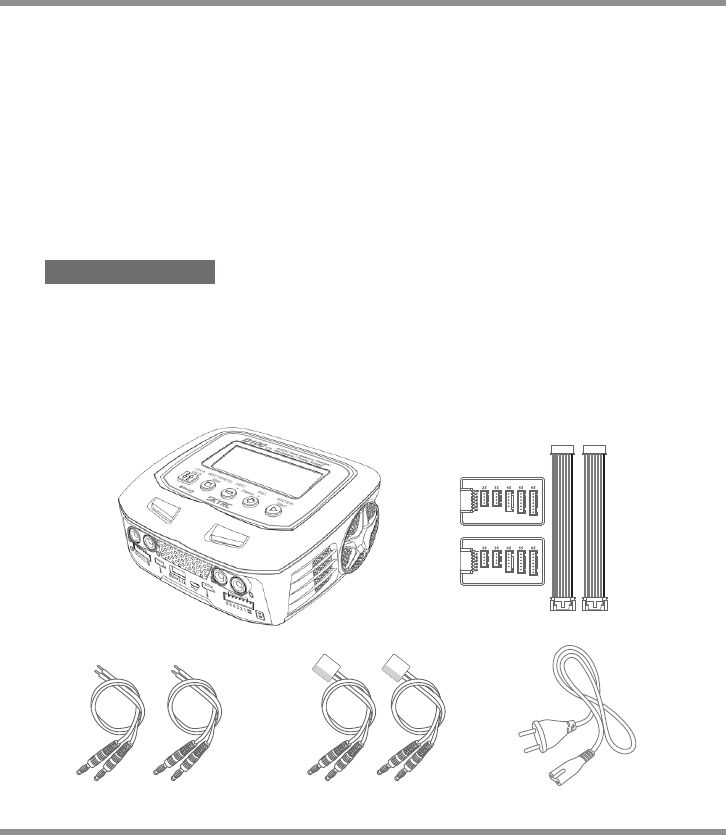
THESETCONTAINS
1. SKYRC D100 V2 Charger
2. XH Adaptor X 2
3. Charging Cable X 2
4. Banana connectors with XT60 connector Charging Cable X 2
5. Power Cord
· 32 D100 V2
Using The Charge Control Software “Charge Master”
35
2
4
1

Specification
DC Input Voltage : 11-18V AC Input Voltage: 100-240V
Display Type: 128x64 LCD Display Backlight: Cool White
Case Material: Plastic Controls: Five Buttons
Case Size: 153x140x67mm Weight: 668g
DC Power Supply Output: 13.8V / Max. 150W
PC Communications: USB Port for PC Control & Firmware Upgrade
External Port: 2-6S Balance Socket-XH, Temperature Probe Socket,
Battery Socket, AC/DC Input, DC Output, Micro USB
Port for PC, 5V-2.1A USB Output.
Delta Peak Detection for NiMH/NiCd: 3-15mV/cell / Default: 4mV/cell
Charge Cut-off Temperature: 20ºC/68ºF-80ºC/176ºF(adjustable)
Charge Voltage: NiMH/NiCd: Delta peak detection
LiPo: 4.18-4.25V/cell LiIon: 4.08-4.2V/cell
LiFe: 3.58-3.7V/cell LiHV: 4.25-4.35V/cell
Balance Current: 300mA/cell
Reading Voltage Range: 0.1-26.1V/cell
Battery Types/Cells: LiPo/LiIon/LiFe/LiHV: 1-6cells
NiMH/NiCd: 1-15cells
Pb: 2-24V
Battery Capacity Range: NiMH/NiCd: 100-50000mAh
LiPo/LiIon/LiFe/LiHV: 100-50000mAh
Pb: 100-50000mAh
Charge Current: (0.1A-10.0A) x2
Safety Timer: 1-720minutes off
Charge Wattage: AC 100W(Support Power Distribution) DC 100Wx2
Discharge Current: (0.1A-2.0A) x2
Discharge Cut-off Voltage: NiMH/NiCd: 0.1-1.1V/cell
LiPo: 3.0-3.3V/cell LiIon: 2.9—3.2V/cell
LiFe: 2.6-2.9V/cell LiHV: 3.1-3.4V/cell
Pb: 1.8-2.0V/cell
Discharge Wattage: 10Wx2
Balance Cells: 2-6 cells
Memory: 10x2 Different Charge/Discharge Profiles
Charge Method: CC/CV for Lithium Types and Lead (Pb) Batteries
Delta-peak Sensitivity for NiMH/NiCd.
33 ·
D100 V2
Conformity Declaration
This symbol means that you must dispose of electrical from the General household waste
when it reaches the end of its useful life. Take your charger to your local waste collection
point or recycling centre. This applies to all countries of the European Union, and to other
European countries with a separate waste collection system.
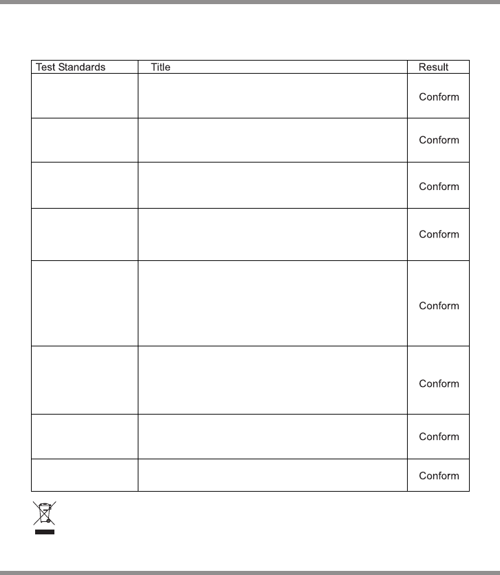
D100 V2 satisfy all relevant and mandatory CE directives and FCC Part 15 Subpart B: 2016.
For CE directives:
The product has been tested to meet the following technical standards:
· 34 D100 V2
EN 300328
EN 301489-1
EN 301489-17
EN 62479
EN 60950-1
Electromagnetic compatibility and Radio spectrum
Matters (ERM); Wideband transmission systems; Data
transmission equipment operating in the 2.4 GHz ISM
band and using wide band modulation techniques;
Harmonized EN covering essential requirements under
article 3.2 of the R&TTE Directive.
Electromagnetic compatibility and Radio spectrum
Matters (ERM); ElectroMagnetic Compatibility (EMC)
standard for radio equipment and services; Part 1:
Common technical requirements. Part 17: Specific
conditions for Broadband Data Transmission Systems.
Assessment of electronic and electrical equipment related
to human exposure restrictions for electromagnetic fields
(0 Hz - 300 Ghz).
Information Technology Equipment-Safety- Part 1: General
Requirements
Electromagnetic Compatibility- Requirements for
household appliances, electric tools and similar
apparatus- Part 1: Emission
Electromagnetic Compatibility- Requirements For
Household Appliances, Electric Tools And Similar
Apparatus- Part 2: Immunity Product Family Standard
Electromagnetic Compatibility (EMC) Part 3-2: Limits for
harmonic current emissions(Equipment input current up
to and including 16A per phase)
Electromagnetic Compatibility (EMC) Part 3-3: Limitation
of voltage supply systems for equipment with rated
current≤16A
EN 55014-1:2006+
A1:2009+A2:2011
EN 55014-2:2015
EN 61000-3-2:2014
EN 61000-3-3:2013

Commonly used terms
Final charge voltage: the voltage at which the battery's charge limit (capacity limit) is
reached. The charge process switches from a high current to a low maintenance rate
(trickle charge) at this point. From this point on further high current charging would cause
overheating and eventual terminal damage to the pack.
Final discharge voltage: the voltage at which the battery's discharge limit is reached. The
chemical composition of the batteries determines the level of this voltage. Below this
voltage the battery enters the deep discharge zone. Individual cells within the pack may
become reverse polarized in this condition, and this can cause permanent damage.
A, mA: unit of measurement relating to charge or discharge current.1000 mA = 1 A
(A=Ampere,mA=Milliampere)
Ah, mAh: unit of measurement for the capacity of a battery (Amperes x time unit; h = hour).
If a pack is charged for one hour at a current of 2 A, it has been fed 2 Ah of energy. It
receives the same quantity of charge (2 Ah) if it is charged for 4 hours at 0.5 A, or 15
minutes (=1/4 h) at 8 A.
'C'-rating: Capacity is also referred to as the 'C' rating. Some battery suppliers recommend
charge and discharge currents based on the battery 'C' rating. A battery's '1C' current is the
same number as the battery's rated capacity number, but noted in mA or amps. A 600mAh
battery has a 1C current value of 600mA, and a 3C current value of (3 x 600mA) 1800mA or
1.8A. The 1C current value for a 3200mAh battery would be 3200mA (3.2A).
Nominal voltage(V): The nominal voltage of the battery pack can be determined as follows;
-.NiCd or NiMH: multiply the total number of cells in the pack by 1.2. A 8-cell pack will have a
nominal voltage of 9.6 volts (8x1.2).
-.LiPo: multiply the total number of cells in the pack by 3.7. A 3-cell LiPo wired in series will
have a nominal voltage of 11.1 volts (3x3.7).
-.LiIo: multiply the total number of cells in the pack by 3.6. A 2-cell LiIo wired in series will have
a nominal voltage of 7.2 volts (2x3.6).
-.LiFe: multiply the total number of cells in the pack by 3.3. A 4-cell LiIo wired in series will have
a nominal voltage of 13.2 volts (4x3.3).
-.LiHV: multiply the total number of cells in the pack by 3.7V. A 4-cell LiHV wired in series will
have a nominal voltage of 14.8 volts (4x3.7).
If the nominal voltage of the battery is not printed on the battery's label, consult your battery
manufacturer or supplier. Do not guess the rated voltage of battery.
Commonly Used Terms
35 ·
D100 V2

Warranty And Service
This charger is designed and approved exclusively for use with the types of battery stated
in this Instruction Manual. SkyRC accepts no liability of any kind if the charger is used for
any purpose other than that stated.
We are unable to ensure that you follow the instructions supplied with the charger, and
we have no control over the methods you employ for using, operating and maintaining the
device. For this reason we are obliged to deny all liability for loss, damage or costs which
are incurred due to the incompetent or incorrect use and operation of our products, or
which are connected with such operation in any way.Unless otherwise prescribed by law,
our obligation to pay compensation, regardless of the legal argument employed, is limited
to the invoice value of those SkyRC products which were immediately and directly
involved in the event in which the damage occurred.
Liability exclusion
Warranty and service
We guarantee this product to be free of manufacturing and assembly defects for a period of
one year from the time of purchase. The warranty only applies to material or operational
defects, which are present at the time of purchase. During that period, we will repair or
replace free of service charge for products deemed defective due to those causes.
This warranty is not valid for any damage or subsequent damage arising as a result of misuse,
modification or as a result of failure to observe the procedures outlined in this manual.
The warranty service is valid in China only.
If you need warranty service overseas, please contact your dealer in the first
instance, who is responsible for processing guarantee claims overseas. Due
to high shipping cost, complicated custom clearance procedures to send
back to China. Please understand SkyRC can't provide warranty service to
overseas end user directly.
If you have any questions which are not mentioned in the manual, please
feel free to send email to info@skyrc.cn
Note:
1.
2.
3.
· 36 D100 V2

All specifications and figures are subject to change without notice.
Printed in China 2017.02
This content is subject to change.
Latest version can be downloaded
from www.skyrc.com
If you have any question about this document, please contact
SkyRC by sending a message to info@skyrc.cn
All Rights Reserved.
7504-0862-01
RoHS
FCC ID: REY-D100V2
FCC Note:
This device complies with Part 15 of the FCC rules. Operation is subject to the following two conditions:
(1) this device may not cause harmful interference, and (2) this device must accept any interference received,
including interference that may cause undesired operation.
The manufacturer is not responsible for any radio or TV interference caused by unauthorized modifications or
change to this equipment. Such modifications or change could void the user’s authority to operate the
equipment.
This equipment has been tested and found to comply with the limits for a Class B digital device, pursuant to
part 15 of the FCC Rules. These limits are designed to provide reasonable protection against harmful
interference in a residential installation. This equipment generates, uses and can radiate radio frequency
energy and, if not installed and used in accordance with the instructions, may cause harmful interference to
radio communications. However, there is no guarantee that interference will not occur in a particular
installation. If this equipment does cause harmful interference to radio or television reception, which can be
determined by turning the equipment off and on, the user is encouraged to try to correct the interference by
one or more of the following measures:
-- Reorient or relocate the receiving antenna.
-- Increase the separation between the equipment and receiver.
-- Connect the equipment into an outlet on a circuit different from that to which the receiver is connected.
-- Consult the dealer or an experienced radio/TV technician for help.
To maintain compliance with FCC’s RF exposure guidelines, this equipment should be installed and operated
with a minimum distance of 20cm between the radiator and your body.