SNAPPER Lawn, Riding Mower Rear Engine Manual L0808227
User Manual: SNAPPER SNAPPER Lawn, Riding Mower Rear Engine Manual SNAPPER Lawn, Riding Mower Rear Engine Owner's Manual, SNAPPER Lawn, Riding Mower Rear Engine installation guides
Open the PDF directly: View PDF ![]() .
.
Page Count: 49

M
S200X Series
Model Number:
5900664
5900692
5900695
5900693
5900694
Description
S200XKAV2561,25HP Kawasaki,61" Cut Zero-TurnRiding Mower
S200XKOH2761,27HP Kohler,61" Cut Zero-Turn Riding Mower
S200XKAV2761,27HP Kawasaki,61" Cut Zero-TurnRiding Mower
S200XBV32,32HP Briggs & Stratton Zero-TurnRiding Mower
$200X/72,72" Mower Deck
Briggs & Stratton Yard PowerProductsGroup
5375 North Main Street
Munnsville, NY 13409
800-933-6175
5101090
RevisionC
Rev.Date:9/2007
TP100-7332-C-M2-SP
Thankyoufor purchasingthis quality-built SnapperPro product. We're pleasedthat
you've placedyour confidencein the SnapperPro brand. When operatedand maintained
accordingto the instructions in this manual,your SnapperPro product will provide many
years of dependableservice.
Thismanual containssafety informationto makeyou awareof the hazardsand
risks associatedwith this machineand how to avoid them. This machine is designedand
intendedto be usedand maintainedaccordingto the manualand operatedby trained
professionalsfor finish cutting of establishedlawnsand is not intendedfor any other
purpose. It is importantthat you readand understandthese instructions thoroughly
beforeattemptingto start or operatethis equipment
Unit Model Number Unit SERIALNumber
Mower Deck Model Number Mower Deck SERIALNumber
DealerName Date Purchased
Engine Make
EngineType/Spec.
EngineModel
EngineCode/SerialNumber
SeeFeatures and Controls for the location of identification Numbers
DATEPURCHASED
Briggs & Stratton Yard Power Products Group
Copyright © 2007 Briggs & Stratton Corporation
Milwaukee, Wl, USA. All rights reserved.
The Snapper Pro logo is a trademark of Briggs & Stratton
Corporation Milwaukee,Wl, USA.
Contact information:
Briggs & Stratton Yard Power Products Group
5375 N. Main St.
Munnsville, NY 13409-4003
(800) 933-6175
www.SnapperPro.com
AWARNING
The engine exhaustfromthis productcontainschemicals
knownto the State of California to causecancer, birth
defects, or other reproductive harm.

Tableof Contents
OperatorSafety..................................................... 2
Safety Rules and Information ...........................................2
Safety Decals..................................................................11
Safety interlock System..................................................12
Features& Controls .............................................. 13
Identification Numbers ...................................................13
Control Functions ...........................................................14
Operation ........................................................... lti
General...........................................................................16
ChecksBefore Starting ...................................................16
CheckingTire Pressures.................................................17
Seat Adjustment .............................................................17
Mowing Height Adjustment ............................................18
Foot PedalAdjustment....................................................18
Raiseand Lower the Roll Bar.........................................19
Starting the Engine.........................................................20
Stopping the Rider..........................................................20
Pushing the Rider by Hand.............................................20
Zero Turn Driving Practice..............................................21
Mowing...........................................................................23
Mowing Reccomendations.............................................23
Mowing Methods............................................................24
Attaching a Trailer...........................................................25
Regular Maintenance ............................................ 26
MaintenanceSchedule....................................................26
Checking/AddingFuel.....................................................27
Fuel Filter........................................................................27
Oil & Filter Change..........................................................27
Lubrication......................................................................28
Check Hydraulic Oil Level...............................................29
Hydraulic Oil Filter Change.............................................29
Servicing the Mower Blades...........................................30
Ground SpeedControl Lever Adjustment .......................32
Speed Balancing Adjustment..........................................32
NeutralAdjustment .........................................................33
Parking BrakeAdjustment ..............................................33
Return to NeutralAdjustment .........................................34
Deck Rod Timing Adjustment .........................................35
Deck Leveling Adjustment ..............................................35
Mower Belt Replacement................................................36
Hydraulic Pump Drive Belt Replacement........................37
Battery Maintenance.......................................................38
Battery Service ...............................................................39
Storage ...........................................................................41
Starting After LongTerm Storage...................................41
Troubleshooting................................................... 42
Troubleshooting the Rider ..............................................42
Troubleshooting the Mower............................................43
Troubleshooting Common Cutting Problems..................44
Specifications ...................................................... 45
NOTE.In this manual, "left" and "right" are referred to as seen
from the operating position.

OperatorSafety
OperatorSafety
Safety Rules and Information
OPERATINGSAFETY
Congratulations on purchasing a superior-quality piece of lawn and
garden equipment. Our products are designed and manufactured to meet
or exceedall industry standards for safety.
Do not operatethis machine unless you have beentrained. Readingand
understanding this operator's manual is a way to train yourself.
Power equipment is only as safe as the operator. If it is misused, or not
properly maintained, it can be dangerous! Remember,you are
responsiblefor your safety and that of those around you.
Usecommon sense, and think through what you are doing. If you are
not sure that the task you are about to perform can be safely done with
the equipment you have chosen,ask a professional: contact your local
authorized dealer.
READTHEMANUAL
The operator's manual contains important safety information
you need to be aware of BEFOREyou operate your unit as
well as DURINGoperation.
Safe operating techniques, an explanation of the product's
features and controls, and maintenanceinformation is
included to helpyou get the most out of your equipment
investment.
Be sure to completely readthe Safety Rules and Information
found on the following pages. Also completely read the
Operation section.
CHILDREN
Tragic accidents can occur with children. Do not
allow them anywhere near the areaof operation.
Children are often attracted to the unit and mowing
activity. Neverassume that children will remain
where you lastsaw them. If there is a risk that
children may enter the areawhere you are mowing,
have another responsibleadult watch them.
2www.SnapperPro.com

OperatorSafety
2O
5.4
SLOPEOPERATION
Operationon slopes can be dangerous. Using the unit on a slope that is
too steepwhere you do not have adequatewheel traction (andcontrol) can
cause sliding, Jossof steering, control, and possible rollover. You should
not operate on a slope greater than a 5.4 foot rise over a 20 foot length (15
degrees).
Always mow across slopes, not up and down (to maintain traction on the
wheels) and avoid sudden turns or rapid speed changes. Reducespeed and
use extreme caution on ALL slopes.
Also, note that the surface condition you are on can greatly impact your
ability to safely operate this machine. Operatingon wet or slippery slopes
can causesliding and loss of steering and control. Do not operateon
slopes that are slippery, wet, or havesoft soil conditions.
If you feel unsure about operating the unit on a slope, don't do it. It's not
worth the risk.
THROWNOBJECTS
This unit has spinning mower blades. Theseblades can pick up andthrow
debris that could seriously injure a bystander. Be sure to clean up the areato
be mowed and remove objects that could bethrown by the blade BEFOREyou
start mowing.
Do not operate this unit without the entire grass catcher or discharge guard
(deflector) in place.
Also, do not allow anyone in the areawhile the unit is running! If someone
does enter the area, shut the unit off immediately until they leave.
MOVINGPARTS
This equipment has many moving parts that can injure you or
someone else. However,if you stay in the operator zone (stay
seated in the seat), and follow the safety rules in this operator's
manual, the unit is safe to operate.
The mower deck has spinning mower bladesthat can amputate
hands and feet. Do not allow anyone near the unit while it is
running! Keepsafety devices (guards, shields, and switches) in
place and working.
To help you, the operator, use this equipment safely, it is
equipped with an operator-present safety system. Do NOT
attempt to alter or bypass the system. Seeyour dealer
immediately if the system does not pass all the safety interlock
system tests found in this manual.

OperatorSafety
ROLL BAR USE
Keep the roJJ bar JR the raised position and fasten the seat
belt. There is no roll over protection when the roll bar is
down! Do not jump off if the mower tips (it is safer to be
secured by the seat belt with the roll bar raised.)
Lower the roll bar only when necessary(such as to
temporarily clear a low overhanging obstacle) and NEVER
removeit. Do NOTuse the seat belt when the roll bar is
down. Raisethe roll bar as soon as clearancepermits.
RETAININGWALLS,DROP-OFFS,ANDWATER
Retaining walls and drop-offs around steps and water are a
common hazard.Give yourself a minimum of two mower widths
of clearancearound these hazardsand hand-trim with a walk
behind mower or string trimmer. Wheels dropping over
retaining walls, edges, ditches, embankments,or into water can
cause roilovers, which may result in serious injury, death, or
drowning.
OVERHEADOBSTACLES
Checkfor overhead clearances before driving under any
objects. Do not allow the roll bar to contact low
overhanging obstacles such as tree branches and guide
wi res.
4 www.SnapperPro.com

OperatorSafety
FUEL AND MAINTENANCE
Always disengageall drives, shutoff the engine, and remove the
key before doing any cleaning, refueling, or servicing.
Gasoline and its vapors are extremely flammable. Do not smoke
while operating or refueling. Do not add fuel while engine is hot
or running. Allow engine to cool for at least 3 minutes prior to
adding fuel.
Do not add fuel indoors, in an enclosed trailer, garage, or any
other enclosed areathat is not well ventilated. Gasolinespills
should be cleanedup promptly and before operation begins.
Gasoline should be stored only in sealed containers approved for
fuel.
Proper maintenanceis critical to the safety and performance of
your unit. Keepthe unit free of grass, leaves,and excess oil. Be
sure to perform the maintenance procedures listed in this
manual, especially periodically testing the safety system.
ENCLOSEDAREAS
Only operate this unit outdoors and away
from unventilated areas such as inside
garages or enclosedtrailers. The engine
emits poisonous carbon monoxide gas and
prolonged exposure in an enclosedarea can
result in serious injury or death.

OperatorSafety
Readthese safety rules and follow them closely. Failureto obeythese rules could result in loss of control of unit,
severe personal injury or deathto you, or bystanders,or damageto property or equipment. This mewing deck is
capable of amputating hands and feet and throwinq objects. The triangle _ in text signifies important cautions
or warnings which must be followed.
TRAINING
1. Read,understand, and follow all instructions in the
manual and on the unit before starting, if the
operator(s) or mechanic(s) can not read English it is the
owner's responsibility to explain this material to them.
2. Becomefamiliar with the safe operation of the
equipment, operator controls, and safety signs.
3. All operators and mechanics should betrained. The
owner is responsiblefor training the users.
4. Only allow responsibleadults, who are familiar with the
instructions, to operate the unit.
5. Neverlet children or untrained peopleoperate or service
the equipment. Local regulations may restrict the age of
the operator.
6. The owner/user can prevent and is responsiblefor
accidentsor injuries occurring to themselves, other
peopleor property.
7. Dataindicates that operators, age 60 years and above,
are involved in a large percentageof riding mower-
related injuries. Theseoperators should evaluatetheir
ability to operate the riding mower safely enough to
protect themselves and others from serious injury.
PREPARATION
1. Evaluatethe terrain to determine what accessoriesand
attachmentsare neededto properly and safely perform
the job. Useonly accessories and attachments
approved by the manufacturer.
2. Wear appropriate clothing including safety shoes, safety
glasses and ear protection. Long hair, looseclothing or
jewelry mayget tangled in moving parts.
3. inspect the areawhere the equipment is to be used and
remove aii objects such as rocks, toys and wire, which
can be thrown by the machine.
4. Useextra care when handling gasoline and other fuels.
They are flammable and vapors areexplosive.
a) Useonly an approved container.
b) Never remove fuel cap or add fuel with the engine
running. Allow engine to cool before refueling. Do
not smoke.
c) Never refuel or drain the machine indoors.
5. Checkthat operator's presencecontrols, safety switches
and shields are attached and functioning properly. Do
not operate unless they are functioning properly.
OPERATION
1. Neverrun an engine in an enclosed area.
2. Mow only in the daylight or with good artificial light,
keeping awayfrom holes and hidden hazards.
3. Besure all drives are in neutral and parking brake is
engaged before starting engine. Only start engine from
the operator's position. Useseat belts if provided.
4. Besure of your footing while using pedestriancontrolled
equipment, especially when backing up. Walk, don't
run. Reducedfooting could causeslipping.
5. Slow down and use extra care on hillsides. Besure to
travel in the recommended direction on hillsides. Turf
conditions can affect the machines stability. Use caution
when operating neardrop-offs.
6. Do not mow in reverseunless absolutely necessary.
Always look down and behind before and while traveling
in reverse.
7. Beaware of the mower discharge direction and do not
point it at anyone. Do not operate the mower without
either the entire grass catcher or the deflector in place.
8. Slow down and use caution when making turns and
when changing directions on slopes.
9. Never raise deckwith the blades running.
10. Never leave a running unit unattended. Always
disengage the PTO,set parking brake, stop engine, and
remove keys before dismounting. Keephands and feet
away from the cutting units.
11. Turn off the PTOswitch to disengagethe blades when
not mowing.
12. Neveroperate with guards not securely in place. Be
sure all interlocks are attached, adjusted properly and
functioning properly.
13. Neveroperate with the discharge deflector raised,
removed or altered, unless using a grass catcher.
14. Do not change the engine governor setting or overspeed
the engine.
15. Stop on level ground, lower implements, disengage
drives, engageparking brake, shut off engine before
leaving the operator's position for any reason including
emptying the grass catchers or unclogging the chute.
16. Stop equipment and inspect blades after striking objects
or abnormal vibration occurs. Makenecessary repairs
before resuming operations.
17. Keephands and feet awayfrom the cutting units.
18. Look behind and down before backing up to be sure of a
clear path.
19. Never carry passengers and keep pets and bystanders
away.
20. Do not operate the unit while under the influence of
alcohol or drugs.
21. Slow down and use caution when making turns and
crossing roads and sidewalks. Stop blades if not
mowing.
22. Usecare when loading or unloading the machine into a
trailer or truck.
23. Usecare when approaching blind corners, shrubs, trees
or other objects that may obscure vision.
24. To reduce fire hazard,keep unit free of grass, leaves&
excess oil. Do not stop or park over dry leaves,grass or
combustible materials.
25. The engine in this unit is not factory equippedwith a
6 www.SnapperPro.com

OperatorSafety
spark arrester. It is a violation of California Public
ResourceCode Section 4442 to use or operate the
engineon or near any forest-covered, brush-covered, or
grass-covered land unless the exhaust system is
equippedwith a spark arrester meeting any applicable
local or state laws. Other states or federal area may
have similar laws.
26. OSHAregulations may require the use of hearing
protection when exposedto sound levels greater than 85
dBAfor an 8 hour time period.
SLOPEOPERATION
Slopesare a major factor relatedto loss-of-control andtip-
over accidents,which can resultin severeinjury or death.All
slopes requireextracaution. If you cannot backup the slope
or if you feel uneasyon it, do not drive on it.
, tL,CAUTION
Ohis machine produces soundlevels in
excess of 85 dBA at the operator's ear and
can cause hearingloss thoughextended
periods of exposure.
Wear hearing protection when operating this machine.
DO
1. Mow across slopes, not up and down.
2. Removeobstacles such as rocks, tree limbs, etc.
3. Watch for holes, ruts, or bumps. Uneventerrain could
overturn the unit. Tall grass can hide obstacles.
4. Useslow speed. Choosea slow speed so that you will
not have to stop or change speedwhile on the slope.
5. Useextra care with grass catchers or other attachments.
Thesecan change the stability of the unit.
AWARNING
Never operateon slopesgreater than15 degrees which
is a rise of 5.4 feet (165 cm) vertically in 20 feet (607
cm) horizontally.
Select slow ground speedbeforedriving onto slope.
Use extra cautionwhen operating on slopes with rear-
mountedgrass catchers.
Mow across the face of slopes,notup and down, use
cautionwhen changingdirections and DO NOTSTART
OR STOPONSLOPE.
6. Keepall movement on the slopes slow and gradual. Do
not make sudden changesin speed or direction.
7. Seeyour authorized dealerfor recommendations of
availableweights to improve stability.
Do Not
1. Avoid starting, stopping, or turning on a slope, if tires
lose traction (i.e. machine stops forward motion on a
slope), disengage the blade(s) (PTO) and drive slow off
the slope.
2. Do not turn on slopes unless necessary,and then, turn
slowly and gradually uphill, if possible. Nevermow
down slopes.
3. Do not mow near drop-offs, ditches, or embankments.
The operator could lose footing or balanceor mower
could suddenly turn over if a wheel is over the edgeof a
cliff or ditch, or if an edge caves in.
4. Do not mow on wet grass. Reducedfooting or traction
could causesliding.
5. Do not try to stabilizethe unit by putting your foot on
the ground. (ride-on units)
6. Do not mow excessivelysteep slopes.
7. Do not use grass catcher on steep slopes.
8. Do not mow slopes if you cannot back up them.
TOWED EQUIPMENT (RIDE-ON UNITS)
1. Tow only with a machine that has a hitch designed for
towing. Do not attach towed equipment except at the
hitch point.
2. Follow the manufacturer's recommendations for weight
limit for towed equipment and towing on slopes. See
attaching a trailer under OPERATION.
3. Neverallow children or others in or on towed
equipment.
4. Onslopes, the weight of the towed equipment may
cause loss of traction and loss of control.
5. Travelslowly and allow extra distance to stop.
6. Do not shift to neutral and coast down hill.
CHILDREN
Tragicaccidentscan occur if the operatoris not alert to the
presenceof children. Childrenare often attractedto the unit
andthe mowing activity. Neverassumethat children will
remainwhereyou last sawthem.
1. Keepchildren out of the mowing area and under the
watchful care of another responsible adult.
2. Bealert and turn unit off if children enter the area.
3. Before and during reverseoperation, look behind and
down for small children.
4. Nevercarry children, even with the blade(s) off. They
may fall off and be seriously injured or interfere with
safe unit operation. Children who have beengiven rides
in the past may suddenly appear in the mowing areafor
another ride and be run over or backedover by the
machine.
5. Neverallow children to operate the unit.
6. Useextra carewhen approaching blind corners, shrubs,
trees, or other objects that may obscure vision.
EMISSIONS
1. Engineexhaust from this product contains chemicals
known, in certain quantities, to cause cancer, birth
defects, or other reproductive harm.
2. Look for the relevant Emissions Durability Periodand Air
indexinformationon the engine emissions label.
IGNITION SYSTEM (GASOLINE MODELS)
1. This spark ignition system complies with Canadian
ICES-O02.

OperatorSafety
SERVICEANDMAINTENANCE
Toavoidpersonalin_v or orooertvdamaoe,useextreme
careinhandlincLQasoline.Gasolineisextremelyflammable
andthevaporsareexplosive.
Safe Handlingof Gasoline
1. Extinguish all cigarettes, cigars, pipes, and other
sources of ignition.
2. Useonly approved gasoline containers.
3. Neverremove the gas cap or add fuel with the engine
running. Allow the engine to cool before refueling.
4. Neverfuel the machine indoors.
5. Neverstore the machine or fuel container where there is
an open flame, spark, or pilot light such as near a water
heater or other appliance.
6. Neverfiii containers inside a vehicle or on a truck bed
with a plastic bed liner. Always place containers on the
ground awayfrom your vehicle before filling.
7. Removegas-powered equipment from the truck or
trailer and refuel it on the ground. If this is not possible,
then refuel such equipment on a trailer with a portable
container, rather than from a gasoline dispenser nozzle.
8. Keepnozzlein contact with the rim of the fuel tank or
container opening at all times until fueling is complete.
Do not use a nozzlelock-open device.
9. If fuel is spilled on clothing, change clothing
immediately.
10. Neverover-fill the fuel tank. Replacegas cap and
tighten securely.
11. Useextra care in handling gasoline and other fuels. They
areflammable and vapors are explosive.
12. If fuel is spilled, do not attempt to start the engine but
move the machine awayfrom the area of spillage and
avoid creating any source of ignition until fuel vapors
have dissipated.
13. Replaceall fuel tank caps and fuel container caps
securely.
Maintenance and Storage
1. Always observe safe refueling and fuel handling
practiceswhen refueling the unit after transportation or
storage.
2. Always follow the engine manual instructions for storage
preparations before storing the unit for both short and
long term periods.
3. Always follow the engine manual instructions for proper
start-up procedureswhen returning the unit to service.
4. Neverstore the machine or fuel container inside where
there is an open flame, such as in a water heater. Allow
unit to cool before storing.
5. Shut off fuel while storing or transporting. Do not store
fuel near flames or drain indoors.
6. Keepall hardware,especially blade attachment bolts,
tight and keep all parts in good working condition.
Replaceall worn or damaged decals.
7. Nevertamper with safety devices. Checktheir proper
operation regularly.
8. Disengagedrives, lower implement, set parking brake,
stop engine and remove key or disconnect spark plug
wire. Wait for all movement to stop before adjusting,
cleaning or repairing.
9. Cleangrass and debris from cutting units, drives,
mufflers, and engineto prevent fires. Cleanup oil or
fuel spillage.
10. Let engine cool before storing and do not store near
flame.
11. Stop and inspect the equipment if you strike an object.
Repair,if necessary,before restarting.
12. Park machine on level ground. Neverallow untrained
personnel to service machine.
13. Usejack stands to support components when required.
14. Carefully releasepressure from components with stored
energy.
15. Disconnect battery or removespark plug wire before
making any repairs. Disconnect the negativeterminal
first and the positive last. Reconnectpositive first and
negativelast.
16. Usecare when checking blades. Wrap the blade(s) or
wear gloves, and use caution when servicing them.
Only replaceblades. Neverstraighten or weld them.
17. Keephands and feet awayfrom moving parts, if
possible, do not make adjustments with the engine
running.
18. Chargebatteries in an open well ventilated area, away
from spark and flames. Unplug charger before
connecting or disconnecting from battery. Wear
protective clothes and use insulated tools.
19. Grasscatcher components are subject to wear,damage,
and deterioration, which could expose moving parts or
allow objects to bethrown. Frequently check
components and replacewith manufacturer's
recommended parts, when necessary.
20. Checkbrake operation frequently. Adjust and service as
required.
21. Use only factory authorized replacement parts when
making repairs.
22. Always comply with factory specifications on all settings
and adjustments.
23. Only authorized service locations should be utilized for
major service and repair requirements.
24. Neverattempt to makemajor repairs on this unit unless
you have been properly trained, improper service
procedures can result in hazardousoperation,
equipment damage and voiding of manufacturer's
warranty.
25. Units with hydraulic pumps, hoses, or motors:
WARNING:Hydraulic fluid escapingunder pressure may
have sufficient force to penetrateskin and causeserious
injury. If foreign fluid is injected into the skin it must be
surgically removed within a few hours by a doctor
familiar with this form of injury or gangrenemay result.
Keepbody and hands awayfrom pin holes or nozzles
that eject hydraulic fluid under high pressure. Use paper
or cardboard, and not hands,to search for leaks. Make
sure aii hydraulic fluid connections are tight and all
hydraulic hosesand lines are in good condition before
applying pressureto the system, if leaks occur, have
the unit serviced immediately by your authorized dealer.
26. WARNING:Stored energy device, improper releaseof
springs can result in serious personal injury. Springs
should be removedby an authorizedtechnician.
8 www.SnapperPro.com

27.Modelsequippedwithanengineradiator:WARNING:
Storedenergydevice.Topreventseriousbodilyinjury
fromhotcoolantorsteamblow-out,neverattemptto
removetheradiatorcapwhiletheengineisrunning.
Stoptheengineandwaituntilitiscool.Eventhen,use
extremecarewhenremovingthecap.
ROLL BAR iNSTRUCTIONS
For models equippedwith factory-installed Roll Over
Protection System(ROPS).
AWARNING
in order to avoid seriousinjury or death from roJJover,
it is importantto follow the warnings listed beJow.
OPERATIONALWARNINGS
•Always use the seat belt when the roll bar is in the
raised position.
•Neveruse the seat belt when the roll bar is in the down
position.
•Rememberthere is no roll over protection when the roll
bar is in the down position so it is very important to
always keepthe roll bar in the raised position whenever
possible.
•Lower the roll bar to the down position only when it is
absolutely necessary.
•Checkfor overhead clearancesbefore driving under any
objects. Do not allow roll bar to contact low
overhanging obstacles such as tree branches and guide
wi res.
•Neverremove the roll bar from the vehicle.
•Do not exceedthe machine weight rating of the roll bar.
•Readand follow all of the instructions shown below
regarding the inspection and maintenanceof the roll bar
structure and the seat belt.
INSPECTIONOF THEROLL BAR PROTECTIVESTRUCTURE
, I WARNING
Failure to properly inspectand maintain the ROLL BAR
protective structurecan causeseriousinjury or death.
A ROLLBAR,like any other safetydevice,needsto be
periodicallyinspectedto verify that the integrity of the device
has not beencompromisedthrough normal machineuse,
misuse,agedegradation,modifications,or a roll over.
To maintainoperator roll over protection and roll bar
effectiveness:
•If a ROLL BAR becomes damaged for any reason, such
as a collision, roll over or impact, the ROLL BAR must
be replaced. Small undetectable cracks can reduce the
effectivenessof the ROLL BAR. Neverweld, straighten,
or repair the ROLL BAR.
•Neveralter the ROLLBAR by welding anything to it or
by drilling additional holes.
•BEFOREFIRSTTllVlEUSE- inspect the ROLL BAR
structure and mounting hardware for:
OperatorSafety
2)
3)
Checkto makesure the machine GVW(Gross
Vehicle Weight), including attachments, restrained
payload,fuel and operator, is not in excessof the
maximum weight specified on the ROLL BAR label.
Makesure there isn't any missing, damaged, or
loose mounting hardware.
Makesure the ROLL BARhas beencorrectly and
completely installed.
EVERY100 HOURS- inspect the ROLL BARstructure
and mounting hardwarefor:
1) Any cracks in the structure (structural members
and/or welds).
2) Significant corrosion on any part of the ROLL BAR
structure or hardware.
3)
4)
5)
Missing, damaged,or loose mounting hardware
Mounting hardware that is of a grade lesser than
specified.
Machine GVW(Gross Vehicle Weight), including
attachments, restrained payload, fuel and operator,
in excess of the maximum weight specified on the
ROLL BARlabel.
6) Any modifications that have been made,such as
unauthorizedwelds and holes.
7) Any permanent deformation or twisting of the ROLL
BARstructure.
8) That the ROLL BARlabel is still in place and is
readable.
9) That the ROLL BARon-product warning labels are
still on the ROLL BAR and are readable.
If there is any doubt as to the condition of the ROLL
BAR,remove the machine from service and contact your
dealer for assistance.

OperatorSafety
,WARNING
Failure to properlyinspectand maintainthe seatbelt
can cause seriousinjury or death.
iNSPECTiONANDMAINTENANCEOFTHEROLL
BARSEATBELT
•The seat belt likethe ROLL BAR, needs to be periodically
inspectedto verify that the integrityhas not been
compromised through normal machine use, misuse, age
degradation, modifications, or a roll over. If the seat belt
does not pass all of the following tests, it should be
replaced.
• BEFOREEACHUSE- Conduct the following
inspections/maintenanceof the seat belt and retraction
mechanism:
1)
2)
3)
4)
Check for dirt or debris in the retraction mechanism.
If dirt or debris is found, it should be removed.
Check to makesure the retraction mechanism
retracts easily and completely.
Check for damageto any part of the seat belt such
as nicks, cuts, loose stitching, or fraying.
Check that the buckle and latch operateproperly and
that the latch plate is not excessivelyworn,
deformed, or the buckle is damaged or cracked. The
seat belt should latch and releaseeasily.
iNSPECTBUCKLE
& LATCH '_
INSPECTWEBBING
10 www.SnapperPro.com

OperatorSafety
Safety Decals
This unit has beendesigned and manufactured to provide
you with the safety and reliability you would expect from an
industry leader in outdoor power equipment manufacturing.
Although readingthis manual and the safety instructions it
contains will provide you with the necessary basic
knowledge to operate this equipment safely and effectively,
we have placed several safety labels on the unit to remind
you of this important information while you are operating
your unit.
All DANGER,WARNING, CAUTION and instructional
messageson your rider and mower should be carefully read
and obeyed. Personal bodily injury can result when these
instructions are not followed. The information is for your
safety and it is important! The safety decals below are on
your rider and mower.
If any of these decals are lost or damaged, replacethem at
once. Seeyour local dealerfor replacements.
Theselabels areeasily applied andwill act as a constant
visual reminder to you, and others who may use the
equipment, to follow the safety instructions necessaryfor
safe, effective operation.
2
AMPUTATION PELIORO DE AMPUTACiGN
AMPUTATION AHD PELIORO DE AI'_PUTACJ()N
THROWN OBJECTS Y OBJETOSARROJADOS
p_raevi_a,s,r_,irI_s_ones
HAZC_OD " hZ
ota _r_ bla es s ay rr a '.f_ d_ I_
a_[ Cepo_et_a¢_ay, _,,l_ ma_te_erala£d_mas er_o_as
bonotmo_wJthout %;_ alea(lasd_lama uirla. NO
disc _arge chute or /-;_ Lsar la m_(i _a sm _ltu_o d_
e_ti e ass catoger .'.÷*_" es_a,ga [} sin el re¢o_edof @
place. :i.. _asto _ s_ _ga. "%
AVOID FiRE H,_ZARD
i'Keef_ uni flee of grass, leaves and excess o;I.
i-STOP eagne and allow to cool for 5 mi_]utes prior to add r,g fuel
i•0o OT add fuel ndoors in an enclosed traler, garage or other
i e_qelosed ar_as.
AVO D CARSON
_ONOX_OE
POiSONiNG
DO NOT o_erate th_
_r_ven gated area,
!!!!!!_
10
11
12 6
PRECAUCION
Avoid serious
injury or death
11 -- I fD_nho_°uti°:il rOai;_:, '
installed and
12 /
11

OperatorSafety
SafetyInterlockSystem
This unit is equippedwith safety interlock
switches. These safety systems are
present for your safety,do not attempt to bypass safety
switches, and never tamper with safety devices. Check
their operation regularly.
Operational SAFETYChecks
TestI-- EngineshouldHOTcrankif:
•PTOswitch is engaged, OR
• Parking brake is not engaged,OR
• Motion control handles are not in the NEUTRAL
position.
Test2 -- EngineSHOULDcrankif:
• PTOswitch is NOTengaged,AND
• Parking brake is engaged,AND
• Motion control handles are locked in the NEUTRAL
position.
Test3 -- EngineshouldSHUT OFFif:
• Operator rises off seatwith PTOengaged, OR
• Operator rises off seatwith parking brake disengaged.
• Operator moves motion control handles out of their
neutral positions before disengaging parking brake.
Test4 -- Blade BrakeCheck
Mower blades and mower drive belt should come to a
complete stop within seven (7) seconds after electric PTO
switch is turned off (or operator rises off seat). If mower
drive belt does not stop within seven (7) seconds, see your
dealer.
NOTE.Once the enginehas stopped, PTOswitch must be
turned off, parking brake must be engaged,and the motion
control handles must be locked in the NEUTRALposition
after the operator returns to the seat in order to start the
engine.
, ,WARNING
If the unit doesnot pass a safetytest, do notoperate
it. See yourauthorizeddealer. Underno
circumstanceshouldyouattemptto defeat the purpose
of the safetyinterlocksystem.
SafetyIcons
The alert symbol _' is used to identity safety information
about hazardsthat can result in personal injury. A signal
word (DANGER,WARNING,or CAUTION)is used with the
alert symbol to indicate the likelihood and the potential
severity of the injury. In addition, a hazard icon may be
used to representthe type of hazard. An explanation of
hazard levels and icons are as follows:
ADANGER
This indicates a hazardwhich, if not avoided, will result in
seriousinjury or death.
_WARNING
This indicates a hazardwhich, if not avoided, couldresult in
serial injury or death.
CAUTION
This indicates a hazardwhich, if not avoided, might result in
minor or moderate injury.
CAUTIONor NOTICE
Thesemessagespresented without the alert symbol indicate
a situation where the unit or property could be damaged.
North American Safety Icons
Hazard
Alert
ToxicFumes
Read the
Manual
OpenFlame
Hazard
Fire Hazard
Amputation
Rotating
Parts
Amputation
Hand in
Blade
Rollover
Hazard
Safety Icon
A
®
Hazard
Amputation
Footin Blade
Thrown
Objects
Maintain a
Safe
Distance
Keep
Children
Away
HotSurface
Wear
Protective
Gear
PinchPoint
Overhead
Obstacles
SafetyIcon
®
O
12 www.SnapperPro.com

OperatorSafety
Featuresand Controls
IdentificationNumbers
When contactingyour authorizeddealer for replacement
parts, service, or informationyou MUST have these
numbers.
Record your part number, serial number and engine serial
numbers in the space provided on the inside front cover for
easy access. Thesenumbers can be found in the locations
shown in Figure 1.
NOTE.For location of engineidentification numbers, refer to
the engineowner's manual. Figure 1. Identification Numbers
A. Identification Tag
13

FeaturesandControls
/
Figure 2. Control Locations
Control Functions
Theinformation below briefly describes the function of individual controls. Starting, stopping, driving, and mowing require
the combined use of several controls appfied in specific sequences. Tolearn what combination and sequenceof controls to
use for various tasks see the OPERATIONsection.
GroundSpeedLevers
Theselevers control the ground speed of the rider. The left
lever controls the left rear drive wheel and the right lever
controls the right rear drive wheel.
Moving a lever forward increasesthe FORWARDspeed of
the associatedwheel, and pulling back on a lever increases
the REVERSEspeed.
Note: Thefurther a lever is moved away from the neutral
position the faster the drive wheel will turn.
See the Operationsection for proper steering instructions.
SeatAdjustmentLever
The seat can be adjusted forward and back. Move the lever
towards the left, position the seat as desired, and releasethe
lever to lock the seat in position.
Ignition Switch
The ignition switch starts and stops the engine, it has three
positions:
Stops the engine and shuts off the
electrical system.
ORUN Allows the to and
engine run powers
the electrical system.
_!_ START Cranks the engine for starting.
NOTE.Neverleave the ignition switch in the RUN position
with the enginestopped-this drains the battery.
14 www.SnapperPro.com

Features& Controls
_Parking Brake
_ DISENGAGE Releasesthe parking brake.
ENGAGE Locks the parking brake.
Pull the parking brake lever back to engagethe parking
brake. Move the lever fully forward to disengage the
parking brake. NOTE.Tostart the unit the parking brake
must be engaged.
_PTO (Power Take Off) Switch
The PTOswitch engages and disengagesthe mower. Pull UP
on the switch to engage, and push DOWNto disengage.
Fuel Tank Cap
To removethe cap, turn counterclockwise.
FuelLevel Gauge
Displaysthe fuel level in the tank.
Deck Lift Pedal, Cutting Height
Adjustment Pin & Deck Lift Lock Lever
Thesecontrol the cutting height of the mower deck.
Depress the pedal until it locks into the 5" (12,7 cm)
position. Placethe adjustment pin in the desired cutting
height and releasethe lift lock lever.
Throttle Control
The throttle controls engine speed. Movethe throttle
forward to increaseengine speed and back to decrease
engine speed. Always operate at FULLthrottle.
_Choke
Closethe choke for cold starting. Openthe choke once the
engine starts. A warm engine may not require choking. Pull
the knob UPto close the choke. Push to knob DOWNto
open the choke.
BHourMeter /MaintenanceReminder
Measures the time of the PTObeing engaged. The hour
meter measuresthe number of hours the PTOhas been
engaged. The hour meter will flash an initial oil change
indicator at 5 hours, and a lubrication reminder every 50
hours. These reminders display for approximately two
hours andwill automatically reset themselves.
Note: Thehour meter will register the passageof time only
when the PTO is engaged. Thehour meter has a self
contained power source so the total hours are always
visible.
15

Operation
Operation
GeneralOperating Safety
Before first time operation:
• Besure to read all information in the Safety and
Operation sections before attempting to operate this
tractor and mower.
• Becomefamiliar with all of the controls and how to stop
the unit.
• Drive in an open areawithout mowing to become
accustomed to the unit.
WARNING
Never allow passengers to ride on the unit.
Before leavingthe operator'sposition for any reason,
engage the parkingbrake, disengagethe PTO,stopthe
engineand removethe key.
Toreducefire hazard, keepthe engine, tractor and
mowerfree of grass, leaves andexcessgrease. Do not
stopor parktractoroverdry leaves, grassor
combustiblematerials.
Gasolineis highly flammable and mustbe handled
with care. Neverfill the tankwhenthe engine is still
hotfrom recentoperation. Donotallow openflame,
smokingor matchesin the area. Avoidover-fillingand
wipe up any spills.
AWARNING
Do notload this zero-turnrider ona trailer or truck
usingtwo separateramps. Onlyuse a single rampthat
is at least onefootwider than the width of the rear
wheels of thisrider. This rider has a zero turning
radiusand the rear wheels couldfall off the ramps, or
the ridercouldtip over injuringthe operatoror
bystanders.
,WARNING
Neveroperateon slopesgreaterthan 17.6 percent
(10°) which is a rise of 3-1/2 feet (106 cm)vertically in
20 feet (607 cm) horizontally.
Select slow groundspeed beforedrivingontoa slope.
Useextra cautionwhen operatingon slopeswith a
rear-mountedgrasscatcher.
Mow acrossthe face of slopes,notup anddown, use
cautionwhen changingdirectionsandDO NOTSTART
ORSTOPONSLOPE.
Checks Before Starting
• Checkthat crankcaseis filled to full mark on dipstick.
Seethe engine Operator's Manual for instructions and
oil recommendations.
• Fillthe fuel tank with fresh fuel. Referto engine manual
for fuel recommendations.
• Makesure all nuts, bolts, screws and pins are in place
and tight.
• Makesure the fuel valve is in the "ON" position.
• Checkthe tire pressures. See Check Tire Pressures.
• Makesure that the Roll Bar is adjusted in the upright
position. See Raiseand Lower the Roll Bar.
• Adjust the seat position, and make certain you can reach
all controls from operator's position. See Seat
Adjustment
• Adjust the height of the mower deck to the desired
position. See Mowing Height Adjustment.
16 www.SnapperPro.com

Operation
CheckTire Pressures
Tire pressure should be checked periodically, and
maintained at the levels shown in the chart. Note that these
pressures may differ slightly from the "Max Inflation"
stamped on the side-wall of the tires. The pressures shown
provide proper traction, improve cut quality, and extend tire
life.
Tire Pressure
Front 25 psi (1,72 bar)
Rear 15 psi (1,03 bar) Figure 3. Checking Tire Pressure
SeatAdjustment
SeeFigure 4. The seatcan be adjusted forward and
backward. Move the lever towards the left, position the seat
as desired, and releasethe lever to lock the seat into
position.
Seat Adjustment (Suspension Seat)
See Figure5. In addition to the forward and backward seat
adjustment, models equippedwith a suspension seat can be
adjusted for lumbar support, suspension and back angle.
Forwardand BackwardAdjustment:
Move the forward /backward seat adjustment lever (A,
Figure 5) away from the seat, position the seat as desired,
and releasethe lever to lock the seat into position.
LumbarAdjustment:
Turn the lumbar adjustment knob (B) until the desired
amount of lumbar is achieved.
BackAngleAdjustment:
Turn the backangle adjustment knob (C) until the desired
amount of back angle is achieved.
SuspensionAdjustment:
Turn the suspension adjustment knob (D) until the display
scale has a readingthat matchesthe weight of the operator.
Figure 4. SeatAdjustment
A. Seat Adjustment Lever
Figure 5. Suspension SeatAdjustment
A. Forward / Backward SeatAdjustment Lever
B. Lumbar Adjustment Knob
C. BackAngle Adjustment Knob
D. Suspension Adjustment Knob
17

Operation
Mowing Height Adjustment
The cutting height adjustment pin (A, Figure 6) control the
mower cutting height. The cutting height is adjustable
between 1-3/4" (4,4 cm) and 5" (12,7 cm) in 1/4" (0,64 cm)
increments.
1. Depressthe deck lift foot pedal (B) until it locks into the
5" (12,7 cm) position.
2. Placethe cutting height adjustment pin in the desired
cutting height.
3. Depressthe deck lift foot pedalthen push the lock lever
(C) toward the right to releasethe lock.
4. Releasethe deck lift foot pedal until it comes to rest
againstthe cutting height adjustment pin.
Figure 6. Mowing Height Adjustment
A. Cutting HeightAdjustment Pin
B. Deck Lift Foot Pedal
C. Deck Lift Lock lever
I
Foot Pedal Adjustment
The deck lift foot pedalcan be adjusted to accommodate the
operator's height for optimal comfort.
Toadjust pedal position:
1. Removethe foot pedal (A, Figure 7) from the pedal
mount tab (B).
2. Removethe pedalmount hardware (C) and rotatethe
tab 180 degrees.
3. Reinstall the pedal mount hardware and tighten securely.
4. Reinstall the foot pedalon the pedal mount tab in the
proper orientation as shown in Figure 7.
%
Figure 7. Foot PedalAdjustment
A. Deck Lift Foot Pedal
B. Pedal Mount Tab
C. Pedal Mount Hardware
D. Optional Position
18 www.SnapperPro.com

Operation
Raise and Lower the Roll Bar
AWARNING
AVOIDSERIOUSINJURYOR DEATHFROM ROLLOVER:
Keeproll bar inthe raised positionand usethe seat
belt.
THEREIS NO ROLLOVERPROTECTIONWHENTHE
ROLLBARIS DOWN
Lower theroll bar onlywhennecessaryand NEVER
remove it.
Do NOTuse seatbelt whenthe roll bar is down.
Raise the roll bar assoonas clearance permits.
Do NOTjump off if mowertips.
ToLower the Roll Bar:
1. Pull the hair pin clips (A, Figure 8) out of the retainer
pins (B).
2. Push or pull the top of the roll bar (C) forward against
the rubber stops (D) and removethe retainer pins (B).
3. Lower the roll bar into the down position (see insert,
Figure 8).
ToRaise the Roll Bar:
1. Pull the hair pin clips (A) out of the retainer pins (B) and
removethe retainer pins.
2. Raisethe roll bar (C) until the rubber stops (D) contact
the upright tubes.
3. Push or pull the top of the roll bar forward against the
rubber stops and reinstall the retainer pins and hair pin
clips to secure the roll bar in the raised position.
Figure 8. Raise& Lower the Rofl Bar
A. Hair Pin Clip
B. Retainer Pin
C. Rofl Bar
D. Rubber Stop
19

Operation
Starting the Engine
AWARNING
If youdo notunderstandhowa specificcontrol
functions,or have notyet thoroughlyreadthe
FEATURES& CONTROLSsection, doso now.
Do NOTattempt to operate the tractorwithoutfirst
becomingfamiliar with the locationandfunctionofALL
controls.
1. While sitting in the operator's seat, engagethe parking
brake by pulling the parking brake lever back, make sure
the PTOswitch is disengaged (pressed down fully) and
the motion control handles are locked in the NEUTRAL
position.
2. NOTE:A warm engine may notrequire choking.
Set the engine throttle control to FULLthrottle position.
Then fully close the choke by pulling the knob OUTfully.
3. Insert the key into the ignition switch and turn it to
START.
4. After the engine starts, gradually open the choke (push
knob down fully). Reduceto half throttle speed and
allow to warm up.
Warm up the engineby running it for at least a minute
before engaging the PTOswitch or driving the rider.
5. Afterwarming the engine, ALWAYSoperate the unit at
FULLTHROTTLEwhenmowing.
In the event of an emergencythe enginecan be stopped
by simp/y turningthe ignition switchto STOP. Usethis
method only in emergencysituations. For normal engine
shut down follow the procedure given in STOPPINGTHE
RIDER.
Stopping the Rider
1. Returning the ground speed control leversto the middle
position will stop rider movement. Pivot the levers
outward and lock them in NEUTRAL.
2. Disengagethe PTOby pushing down on the PTOswitch.
3. Engagethe parking brake by pulling the handle up until
it locks into position.
4. Move the throttle control to mid-throttle position and
turn the ignition keyto OFF. Removethe key.
Pushing the Rider By Hand
NOTICE
DONOTTOW RIDER
Towingthe unitswill causehydraulicpumpandwheel
motordamage. Donot use anothervehicle to pushor
pullthis unit.
1. Disengagethe PTO,engagethe parking brake,turn the
ignition OFF,and removethe key.
2. Lift the seat plate to gain access to the hydraulic pumps.
3. To disengage the pumps (free-wheel position), turn the
hydraulic releasevalves (A, Figure 9) locatedon the
pumps COUNTER-CLOCKWISEa maximum of 2 full
turns.
4. Disengagethe parking brake.
The tractor can now be pushed by hand.
5. After moving the tractor, re-engagethe pumps (drive
position) by turning the releasevalves CLOCKWISEand
tighten to 80-120 in. Ibs.of torque.
Figure 9. Hydraulic System By-Pass
A. Hydraufic ReleaseValve
(left-hand pump shown)
20 www.SnapperPro.com

Operation
ZeroTurnDrivinuPractice
The lever controls of the Zero Turn rider are responsive,and
learning to gain a smooth and efficient control of the rider's
forward, reverse, and turning movements will take some
practice.
Spending some time going through the maneuvers shown
and becoming familiar with how the unit accelerates,travels,
and steers -- before you begin mowing --is absolutely
essential to getting the most out of the Zero Turn rider.
Locate a smooth,flat area of your lawn -- one with plenty
of room to maneuver.(Clear the area of objects, peopleand
animals beforeyou begin.) Operatethe unit at mid-throttle
during this practice session (ALWAYSoperate at full throttle
when mowing), and turn slowly to preventtire slippage and
damage to your lawn.
We suggest you beginwith the Smooth Travelprocedure to
the right, andthen advancethrough the forward, reverse,
and turning maneuvers.
You must releasethe parking brake prior to moving the
control levers inward.
Smooth Travel
The lever controls of the
Zero Turn rider are
responsive.
The BESTmethod of
handling the ground
speed control levers is in
three steps -- as shown
in Figure 10.
FIRSTplace your hands
onto the levers as shown.
SECOND,to go forward
gradually push the levers
forward with your palms.
THIRD,to speed up move
the levers farther
forward. To slow down
smoothly, slowly move
the levers toward neutral.
Figure 10. Move Control
Levers Gradually
ForwardTravel Practice
Gradually move both ground speed control levers-- evenly
FORWARDfrom neutral. Slow down and repeat.
NOTE.Straight forward travel takes practice. If necessary,
top speed can be balance-adjusted-- see the Speed
Balancing Adjustment in the Adjustments section near the
back of this manual.
ReverseTravel Practice
LOOKDOWN& BEHIND,then gradually move both ground
speed control levers evenly BACKfrom neutral. Slow down
and repeat.
NOTE.Practice backing up for severalminutes before
attempting to do so near objects. The rider turns sharply in
reverseas well as forward, and backing up straight takes
practice.
Forward
Travel
-//._
Reverse
Travel i
i
Figure 11. Forward Travel Figure 12. Reverse Travel
21

Operation
Practice TurningArounda Corner
While traveling forward allow one handleto gradually return
back toward neutral. Repeatseveral times.
NOTE. Toprevent pivoting directly on the tire tread, it is best
to keep both wheelsgoing at least slightly forward.
Practice Turning In Place
To turn in place, "Zero Turn," gradually move one ground
speed control lever forward from neutral and one lever back
from neutral simultaneously. Repeatseveraltimes.
NOTE.Changing the amount eachlever is puffed--forward
or back, changes the "pivot point" you turn on.
Executing
Turns
Figure 13. TurningAround a Comer
Turning
In-Place
Figure 14. Turning in Place
Executingan End-Of-RowZeroTurn
Your Zero Turn Rider's unique ability to turn in
place allows you to turn around at the end of a
cutting row rather than having to stop and Y-turn
before starting a new row.
For example,to execute a left end-of row zero
turn:
1. Slow down at the end of the row.
2. Move the RIGHTground speed control lever
forward slightly while moving the LEFT
ground speed control lever back to center and
then slightly backfrom center.
3. Begin mowing forward again.
This technique turns the rider LEFTand slightly
overlaps the row just cut --eliminating the need
to back up and re-cut missed grass.
As you become more familiar and experienced
with operating the Zero Turn rider,you will learn
more maneuvers that will makeyour mowing
time easier and more enjoyable.
Remember,the moreyou practice, the better
your controlof the Zero Turnwill be!
Figure 15. Executing an End-Of-Row Turn
22 www.SnapperPro.com

Operation
Mowing
1. Engagethe parking brake. Make sure the PTOswitch is
disengaged,the motion control levers are locked in the
NEUTRALposition andthe operator is on the seat.
2. Start the engine (see Starting The Engine).
3. Set the mower cutting height (see Mowing Height
Adjustment).
4. Set the throttle to FULL.
5. Engagethe PTOby pulling up on the PTOswitch.
6. Begin mowing. See Mowing Recommendationsfor tips
on mowing patterns, lawn care, and trouble shooting
information.
7. When finished, shut off the PTOby pushing the PTO
switch down completely..
8. Stop the engine (see Stopping The Rider and Engine).
Mowing Recommendations
Severalfactors can affect how well your machine cuts grass,
Following proper mowing recommendations can improve
the performance and life of your machine.
Heightof Grass
Often cutting height is a matter of personal preference.
Typically,you should mow the grass when it is is between
three and five inches high. The proper cutting height range
for a specific lawn will depend upon several factors,
including the type of grass, the amount of rainfall, the
prevailing temperature, and the lawn's overall condition.
Cutting the grass too short causes weak, thin grass plants,
which are easily damaged by dry periods and pests. Cutting
too short is often more damaging than allowing the grass to
be slightly higher.
Letting grass grow a bit longer--especially when it is hot
and dry--reduces heat build-up, preserves neededmoisture
and protects the grass from heat damage and other
problems. However,allowing grass to grow too high can
causethin turf and additional problems.
Cutting off too much at one time shocks the plant's growth
system and weakens the grass plants. A goodrule of thumb
is the 1/3 rule: to cut no more thanone third of the grass
height, and nevermore than1 inch at a time.
The amount of grass you are able to cut in one pass is also
effected by the type of mowing system you are using (for
example, broadcasting with side discharge decks can
process a much larger volume of grass than mulching
does).
l
Figure 16. Proper Cutting Height
Tall GrassRequiresIncremental Cutting
For extremely tall grass, set the cutting height at maximum
for the first pass, and then reset it to the desired height and
mow a second or third time.
Don't cover the grass surface with a heavy layer of
clippings. Consider using a grass collection system and
starting a compost pile.
Cut Here On
First Pass Cut Here
'k_ On Second
t s,// Pass
J!|l//t,MJtit|I,L!7"
Figure 17. Incremental Cutting
23

Operation
When and How Often to Mow
The time of day and condition of the grass greatly affect the
results you'll get when mowing. Forthe best results, follow
these guidelines:
1. Mow when the grass is betweenthree and five inches
high.
2. Mow with sharp blades. Short clippings of grass one
inch or shorter decompose more quickly than longer
blades.Sharp mower blades cut grass cleanly and
efficiently, preventing frayed edgeswhich harm the
grass.
3. Mow at time of day when the grass is cool and dry. Late
afternoon or early evening often provide these ideal
mowing conditions.
4. Avoid mowing after rain or even heavy dew,and never
mulch when the grass is wet (moist grass does not
mulch well, and clumps beneaththe mower deck).
Mowing Patterns
Always start mowing on a smooth, level area.
The size and type of areato be mowed will determine the
best mowing pattern to use. Obstructions such as trees,
fences and buildings, and conditions such as slopes and
grades must also be considered.
1. Cut long straight strips overlapping slightly.
2. Where possible, change patterns occasionally to
eliminate matting, graining or a corrugated appearance.
3. For a truly professional cut, mow across the lawn in one
direction, then recut the lawn by mowing perpendicular
to the previous cut.
Note:Always operatethe engineat full throttle when
mowing.
If you hearthe engine slowing down, you are mowing too
fast--using a slower ground speed will improve the cutting
efficiency of the blades and prevents many common cutting
problems. Use an appropriate ground speed for the
thickness and height of the grass you are cutting (3rd gear
or slower for manualgear models). If you hear the engine
slowing down you are mowing too fast, use a slower ground
speed.
Wherepossible, make one or two passesaround the outside
of the areadischarging the grass INTOthe lawn to keep the
cut grass off fences and walks.
The remainder of the mowing should be done in the
opposite direction so that the clippings are dispersed OUT
onto the areaof lawn previously cut.
Mowing Methods
Proper BroadcastMowing
Broadcasting,or side-discharging, disperses fine clippings
evenly over the entire lawn. Many golf courses use this
method. Your mower has a deep dish deck to allow freer
circulation of clippings so they are broadcast evenlyover the
lawn.
EngineSpeed& GroundSpeedfor Broadcasting
Always operatethe engineat full throttle when mowing. If
you hear the engine slowing down, you are mowing too
fast--using a slower ground speed will improve the cutting
efficiency of the blades and prevents many common cutting
problems.
ALWAYSuse an appropriate ground speed for the thickness
and height of the grass you are cutting (3rd gear or slower
for manual gear models). If you hearthe engine slowing
down you are mowing too fast, use a slower ground speed.
How MuchGrassto CutOffWhen Broadcasting
Mow when the grass is 3-5 inches long. Do not cut the
grass shorter than 2 to 2-1/2 inches. Do not cut off more
that 1 inch of grass in a single pass
24 www.SnapperPro.com

Operation
Proper Mulching
Mulching consists of a mower deckwhich cuts and recuts
clippings into tiny particles and which then blows them
down INTOthe lawn. These tiny particles decompose rapidly
into by-products your lawn can use. UNDERPROPER
CONDITIONS,your mulching mower will virtually eliminate
noticeable clippings on the lawn surface.
NOTE:When mulching under heavycutting conditions, a
rumbling sound may be present and is normal.
Mulching RequiresEXCELLENTMowing Conditions
Mulching mowers cannot function properly if the grass is
wet, or if the grass is simply to high to cut. Even more than
normal mowing, mulching requires that the grass be dry
and the the appropriate amount is cut.
Do not usethe mower as a mulching mower during the first
two or three mowings in the spring. The long grass blades,
quick growth, and often wetter conditions are more suitable
for broadcasting (side-discharging) or grass bagging
operation.
EngineSpeed & GroundSpeedfor Mulching
Usefull enginethrottle matched with a slow ground speed
so that clippings will be finely cut. Ground speedwhile
mulching should be HALFof the speed that would be used
when broadcasting (side discharging) under similar
conditions. Since mulching requires more horsepowerthan
broadcasting, using a slower ground speed is vitally
important for proper mulching operation.
How Much Grassto Mulch
The best mulching action typically results from cutting only
the top 1/2 inch to 3/4 inch of grass blade. This provides
short clippings which decompose properly (much more
quickly than longer clippings). The ideal cutting height will
vary with climate, time of year, and quality of your lawn. We
recommend that you experiment with both the cutting height
and ground speed until you achievethe best cut. Start with a
high cutting height and using progressively lower settings
until you find a cutting height that is matchedto your
mowing conditions and preferences.
AttachingA Trailer
The maximum weight of a towed trailer should be less than
200 Ibs (91kg). Secure the trailer with a appropriately sized
clevis pin (A, Figure 19) and clip (B).
Excessivetowed loads can cause loss of traction and loss of
control on slopes. Reducetowed weight when operating on
slopes. The surface being driven on greatly impacts traction
and stability. Wet or slippery surfaces can greatly reduce
traction and the ability to stop or turn. Carefully evaluatethe
surface conditions before operating the unit and trailer, and
never operate on slopes greater than 10°. SeeSLOPE
OPERATIONand TOWEDEQUIPMENTin the safety section
of this manual for additional safety information.
0
(lm)
20' (6m) ?
Figure 19. Trailer Weight Recommendations
A. Clevis Pin
B. Clip
Figure 18. Mulching Action
25

RegularMaintenance
RegularMaintenance
MaintenanceSchedule
The following schedule should be followed for normal care of your rider and mower. You will needto keep a record of your
operating time. Determiningoperating time is easily accomplished by observing the elapsedtime recorded by the hour meter.
SafetyItems Before Every5 Every25 Every100 Every250 Spring&
EachUse Hours Hours Hours Hours Fall
Check Safety Interlock System
Check Rider Brakes
Check Mower BladeStopping Time
Rider Maintenance Before Every5 Every25 Every100 Every250 Spring&
EachUse Hours Hours Hours Hours Fall
Check Rider /Mower for loose hardware
CleanDeck& Check/ReplaceMower Blades**
Lubricate Rider & Mower **
Clean Battery & Cables
CheckTire Pressure
Check Hydraulic Oil
Change Hydraulic Oil Filter **
EngineMaintenance Before Every5 Every25 Every100 Every250 Spring&
EachUse Hours Hours Hours Hours Fall
Check EngineOil Level
Check/Clean Cooling Fins& Intake **
Service Air Filter *
Change Oil & Filter *
Check/ReplaceSpark Plugs *
Check/ReplaceFuel Filter *
* Referto engine owner's manual. Changeoriginal engine oil after initial break-in period.
** More often in hot (over 85° F: 30° C)weather or dusty operating conditions.
26 www.SnapperPro.com

RegularMaintenance
Checking /Adding Fuel
To add fuel:
1. Removethe fuel cap.
2. Fill the tank to about 1-1/2" (3,81 cm) of the bottom of
the filler neck. This will allow for fuel expansion.
NOTE. Do not overfill. Refer to your engine manual for
specific fuel recommendations.
3. Install and hand tighten the fuel cap.
Fuel Filter
The fuel filter is locatedin the fuel line betweenfuel tank and
carburetor, nearthe fuel pump. If filter is dirty or clogged,
replace as follows:
1. Disconnect the negative battery cable.
2. Placea container below the filter to catch spilled fuel.
3. Using pliers, open and slide hose clamps from fuel filter.
4. Remove hosesfrom filter.
5. Install new filter in proper flow direction in fuel line.
6. Securewith hose clamps.
7. Reconnectthe negative battery cable when finished.
Change Oil & Filter
1. Warm engine by running for a few minutes. (Refer to
the engine operator's manual for oil & filter replacement
instructions.)
2. Removethe oil drain hose (A, Figure 20) from the cable
clamp (C) that is located on the engine deck on the
right-hand side of the frame. Placethe drain hose down
through the hole (E) in the engine deck.
3. Placea small pan under the oil drain hose to catch the
oil. Using the appropriate tools, remove the cap (B)
from the oil drain hose (A) and drain the engineoil into
the pan.
4. After draining, replacethe cap and wipe up any spilled
oil. Reinstall the oil drain hose into the cableclamp to
retain the hose during normal operation.
5. Placean absorbent shop cloth under the engineoil filter.
Removethe engine oil filter and replacewith a new one.
6. Removethe shop cloth and wipe up any spilled oil.
EngineMaintenance
Refer to engine owner's manual for all engine maintenance
procedures and recommendations.
WARNING
Gasolineis highlyflammable and mustbe handled
with care. Neverfill the tank whenthe engineis still
hotfrom recentoperation. Donot allow open flame,
smokingor matchesin the area. Avoidover-fillingand
wipe up any spills.
Donot removefuel filter whenengine is hot, as spilled
gasoline may ignite. DO NOTspreadhoseclamps
furtherthannecessary.Ensureclampsgrip hoses
firmly overfilter after installation.
NOTICE
Donot use gasoline containingMETHANOL,gasohol
containingmorethan10% ethanol, gasoline additives,
premiumgasoline, or white gas becauseengine/fuel
systemdamage couldresult.
Figure 20. Engine Oil Drain
A. Oil Drain Hose
B. Cap
C. Cable Clamp
D. Oil Filter
E. Hole for Drain Hose
27

RegularMaintenance
Lubrication
Lubricate the unit at the locations shown in Figures 21
through 24 as well as the following lubrication points.
Grease:
i•front caster wheel axles & yokes
• deck lift pivot blocks
• mower deck spindles
• mower deck idler arm
Use greasefittings when present. Disassemble parts to
apply grease to moving parts when grease fittings are not
installed.
Not all greases are compatible. Red Grease(p/n 5022285)
is recommended,automotive-type high-temperature, lithium
grease may be used when this is not available.
Oil:
• control handle pivots
• seat plate pivots
• deck lift pivots• discharge chute hinge
Generally,all moving metal parts should be oiled where
contact is made with other parts. Keepoil and greaseoff
belts and pulleys. Rememberto wipe fittings and surfaces
clean both before and after lubrication.
Lubricatingthe FrontCasters:
NOTE.Front casters should be lubricated annually.
1. Removethe 1/4-28 bolt (A, Figure 24) screwed into the
front caster and install a 1/4-28 grease fitting.
2. Greasethe front caster.
3. Removethe 1/4-28 grease fitting and reinstall the 1/4-28
bolt.
4. Repeatprocess for the other side of the machine.
Figure 21. Deck Lubrication
........
:: i_ .........
/i
/
/
// i
//
Figure 22. Control Handle Pivots & Seat Plate Pivots
Figure 23. Deck Lift Linkage Pivots
\
Figure 24. Front Caster & Wheel
A. 1/4-28 Bolt
28 www.SnapperPro.com

RegularMaintenance
Check Hydraulic Oil Level
1. Before removing the reservoir cap, makesure the area
around the reservoir cap and fill neck of the reservoir is
free of dust, dirt, or other debris.
2. Unscrew the reservoir cap (B, Figure25).
3. Look down the filler neck of the hydraulic oil reservoir
(A) and observethe oil level. When cold, the oil level
should be approximately 4" (10 cm) below top of the
filler neck.
4. If necessary, removethe reservoir cap (B) and add SAE
20W-50 motor oil.
5. Reinstall the reservoir cap.
Change Hydraulic Oil Filter
ChangeInterval:Every 250 Hours
Filter Part Number:1719168
NOTE. Removingthe oil filter from the filter base will drain
the oil reservoir. Havea suitable container ready to catch
any spilled oil. Themanufacturer recommends this be a
dealer-only service item.
1. Locatethe transmission oil filter (B, Figure 26) at the
rear of the battery compartment under the seat.
2. Lubricate the new filter base with a few drops of
transmission oil. Fill the filter half full of oil.
3. Cleanthe areaaround the filter baseand removethe
filter. Do NOTdrain the hydraulic system oil.
4. Thread the new filter onto the filter base until the gasket
makes contact, then tighten 3/4 of a turn more.
5. Run the unit for several minutes and check the
transmission oil level.
IMPORTANTNOTE:Usecaution after changing the filter, air
in the hydraulic system may affect the responsiveness of the
control levers. Repeatstep 5 until the air is out of the
system.
Figure 25. Checking Hydraulic Oil Level
A. Hydraufic Oil Reservoir
B. Reservoir Cap
Figure 26. Battery Compartment
A. Hydraufic Oil Reservoir
B. Hydraufic OilFilter
29

RegularMaintenance
ServicingThe Mower Blades
Removingthe Mower Blade
ACAUTION
Avoidinjury! Mower bladesare sharp.
•Alwayswear gloveswhen handlingmower blades or
workingnear blades.
1. To removethe mower blade, use a 1" wrench on the
flats of the spindle shaft and remove the mower blade
mounting bolt with a 15/16" wrench (Figure 27).
2. If there are no flats on the spindle shaft, wedge a
wooden block betweenthe mower blade andthe mower
deck housing to keepthe mower bladefrom turning.
Inspectingthe Mower Blades
ADANGER
Avoidinjury! A worn or damagedblade can break, and
a pieceof the mowerblade couldbe throwninto the
operator'sor bystander'sarea, resultingin serious
personal injuryor death.
•Inspectthe mowerblade every 25 hoursor at least
oncea year.
•If the mower blade hitsa solid object, stopthe
engine immediatelyand inspectthe mower blade.
•Neverweld or straightenbentmower blades.
1. Removethe mower bladefrom the unit. SeeRemoving
the Blade.
2. Inspect the mower blade (Figures 28 & 29). Discardthe
mowerblade if it has any of the below conditions.
A.) Has more than .5" (12,7 mm) of the mower blade
metal removed from previous sharpening or wear (D,
Figure 28).
B.) The air lifts are excessivelyeroded (B & C, Figure
29) andthe notch (C) is .25" (6,35 mm) deep or greater.
C.) Mower blade is bent or broken.
3. If the cutting edges are not sharp or have nicks, sharpen
the blades. SeeSharpeningthe Mower Blades.
Figure 27. Loosening the Mower Blade for Removal
J
J
.............................................................................................. \
i ........................................................................................... \
Figure 28. inspecting the Mower Blade Tips
A. Mower BladeCutting Edge
B. SquareComer
C. Air Lift
D. Wear Measurement -DISCARDMower BladeIf greater
than .5" (12,7 mm)
®
Figure 29. inspecting the Mower BladeAir Lifts
A. New Mower Blade
B. Mower Bladeat WearLimit (A notch begins to form)
C. Mower Bladein Dangerous Condition (Notch measures .25" (6,35 mm) or greater DO NOTUSE.Replacewith new mower
blade.)
30 www.SnapperPro.com

RegularMaintenance
Sharpening the Mower Blade
ACAUTION
Avoidinjury! Mower bladesare sharp.
•Alwayswear gloves whenhandlingthe mower
blades.
•Alwayswear safetyeye protectionwhen grinding.
1. Sharpenthe mower bladeswith grinder, handfile, or
electric bladesharpener.
2. Sharpenthe mower blade by removing an equal amount
of material from each end of the mower blade.
3. Keepthe original bevel (A, Figure 30) when grinding. DO
NOTchange the mower blade bevel.
4. The mower blade should have a maximum 1/64" (0,40
mm) cutting edge (B) or less.
5. Balancethe mower blades before installing.
®
Figure 30. Sharpeningthe Mower Blade
A. Mower BladeBevel
B. Mower BladeCutting Edge
Balancingthe Mower Blades
CAUTION
Avoidinjury! Keepmower bladesbalanced.
*Anunbalancedmower blade can create excessive
vibrationanddamage the unit or cause mowerblade
failure.
1. Cleanthe mower bladeto removeany dried grass or
other debris.
2. SeeFigure 31. Put the mower blade on a nail in a vise
andturn the mower bladeto the horizontal position.
3. Checkthe balance of the mower blade. If either end of
the mower blademoves downward, sharpen the heavy
end until the mower blade is balanced. SeeSharpening
the Mower Bladesfor proper sharpening instructions.
4. Repeatthe process until the mower blade remains in the
horizontal position.
Reinstallingthe Mower Blades
1. Reinstall each mower blade with the air lifts pointing up
towards the mower deck as shown in Figure32. Secure
with the mower blade mounting bolt and flat washer (A
& B, Figure 32) and torque to 70 ft. Ibs (94 Nm).
2. If there are no flats on the spindle shaft, wedge a
wooden block betweenthe mower blade andthe mower
deck housing to keepthe mower bladefrom turning.
Figure 31. Balancing the Mower Blade
A. Nail
\
Figure 32. Tighteningthe Mower Blade for Installation
A. Mower Blade Mounting Bolt
B. Flat Washer
C. Mower BladeAir Lift (Points Up For Installation)
D. 4 X 4 Wooden Block
31

RegularMaintenance
GroundSpeedControlLeverAdjustment
The control levers can be adjusted in three ways. The
alignment of the control levers, the placement of the levers
(how close the ends areto one another) and the height of
the levers can be adjusted.
ToAdjustthe HandleAlignment
Loosen the mount bolts (A, Figure33) and pivot the lever(s)
(B) to align with each other.
ToAdjustthe Handle Placement
Loosen the jam nuts and adjust the placement bolt (C,
Figure 34) in or out to properly adjust the lever end spacing.
To Adjustthe Handle Height
Remove the mounting hardware and reposition the handle
either up or down from its original position. Youwill need
to readjust the handle alignment as described above.
Speed Balancing Adjustment
If the rider veers to the right or left when the ground speed
control levers are in the maximum forward position, the top
speed of each of these levers can be balanced by turning the
adjustment bolt(s) (A, Figure 34). Only adjust the speed of
the wheel that is traveling faster.
ToReducethe Speedof the FasterWheel
1. Loosen the securing nut.
2. Turn the top speed adjustment bolt COUNTER-
CLOCKWISEto reducethe speed.
3. Retighten the securing nut when adjustment is
complete.
,AWARNING
DO NOTadjust the tractorfor a faster overall speed
forwardor reversethanit was designedfor.
Figure 33. Control Lever Adjustment
A. Placement Hardware
B. Ground S_eedControl Lever
Figure 34. Top SpeedAdjustment
A. TopSpeedAdjustment Bolt
B. Control Lever Base
C. Alignment Hardware
32 www.SnapperPro.com

RegularMaintenance
Neutral Adjustment
If the tractor "creeps" while the ground speed control levers
are locked in NEUTRAL,then it may be necessaryto adjust
the linkage rod.
NOTE.Perform this adjustment on a hard, level surface such
as a concrete floor
1. Disengagethe PTO,engagethe parking brake and turn
off the engine.
2. There arethree nuts (B, Figure35) on the linkage rod
(A). The first two are to be used together to turn the rod
andthe third (towards the front of the machine) is used
to lock the rod in place. Loosen the jam nutthat locks
againstthe ball joint and turn the linkage rod to adjust.
If the machine creepsforward, turn the rod CLOCKWISE
(while standing at the rear of the machine, facing
forward), if the machinecreeps backward,turn the rod
COUNTER-CLOCKWISE.
3. Lock the jam nut (B) against the ball joint when neutral
is achieved.
NOTE. This adjustment should not be performed while the
machine is running. It may take severalattempts to achieved
neutral, depending upon how much the machine creeps.
Figure35. Neutral Adjustment
(LH side shown)
A. Adjustment Linkage Rod
B. Nuts
Parking Brake Adjustment
1. Disengagethe PTO,stop the engine, block the front
wheels, remove the ignition key,and engagethe parking
brake.
2. Locatethe brake spring (A, Figure 36).
3. With the parking brake engaged, measurethe
compressedspring length. The spring should be 2" to
2-1/8" (5,0 - 5,4 cm) when compressed.
4. If the spring is not within this range, releasethe parking
brake and turn the adjustment nut (B) to compress or
releasethe spring.
5. Engagethe parking brake and remeasurethe spring.
ACAUTION
Do notadjustthe springto be shorterthan
1-15/16" (4,9 cm) whencompressed. This may
damagethe brakemechanism.
If this doesnot correctthe braking problem, seeyour
SnapperProdealer.
_=__._____--- 2" - 2-1/8"
='- / (5,0 - 5,4cm)
Figure 36. Parking Brake Adjustment
A. Brake Spring
B. Adjustment Nut
33

RegularMaintenance
Return-To-NeutralAdjustment
To determine if it is necessaryto adjust the neutral return,
perform the following steps.
1. Disengagethe PTO,engagethe parking brake and turn
off the engine.
2. Move the ground speed control levers into the operating
position, pull levers rearward and release.
3. Move the ground speed control levers out towards the
neutral position. If the leversdo not align with the
notches in the neutral lock plate, it is necessaryto
adjust the adjustment linkage rod (B, Figure37).
AWARNING
Toavoid seriousinjury, perform adjustmentsonly with
enginestopped, keyremovedandtractor onlevel
ground.
Adjustment
1. Pull the ground speed control lever rearward and release
to check position. If the ground speed control lever
does not align itself with the notch in the neutral plate,
then move the set collar (A) forward or back on the
adjustment linkage rod (B) until the speed control lever
aligns with the notch. Retightenthe set collar.
2. Makesure that the neutral return bushing (D) is seated
correctly in the spring stop plate (E).
3. Pull the ground speed control lever rearward and release
to check position again. Adjust as necessaryto align
the ground speed control levers with the notches in the
neutral lock plate.
It is important to note that after every adjustment of the
neutral return rod, the lever must be pulled rearward and
released to properly check the neutral position.
Figure 37.
A.
B.
C.
D.
E.
Neutral Return Spring Adjustment
Set Collar
Adjustment Linkage Rod
Neutral Return Spring
Neutral Return Bushing
Spring Stop Plate
34 www.SnapperPro.com

RegularMaintenance
Deck Rod Timing Adjustment
1. Park the machine on a flat, level surface. Disengagethe
PTO,engagethe parking brake,turn off the engine,and
removethe ignition key. Rear tires must be inflated to
15 psi (1,03 bar); front tires to 25 psi (1,72 bar).
2. To check the lift rod timing, measure and record the
distance betweenthe lift pivots and the rod pivots.
Repeatfor other side of unit. SeeFigure 38.
3. If the measurements for the rods are equal, no further
adjustment is required. If the measurements are NOT
equal (greater than 1/8" (3,17 mm) difference),
adjustment is required continue with Step 4.
4. Lock the deck lift pedal in the 5" (12,7 cm) position.
Removethe cutting height adjustment pin and lower the
mower deck.
5. To ensure that the deck is in the lowest position, push
the pedalby hand towards the rear of the unit and install
the height adjustment pin in the 3" (7,6 cm) position to
hold in place.
6. Block up the mower deck until all hanger chains are
slack. Referto Figure 40.
7. SeeFigure 39. To adjust the lift rod, loosen the jam nut
on the front clevis then remove the 1/2" clevis pin
fastening the clevis to the lift pivot arm. Turn the clevis
clockwise to shorten the distance betweenthe rod pivots
or counterclockwise to lengthen the distance between
the rod pivots. Reinstall the clevis on the lift pivot arm
and securewith the 1/2" clevis pin previously removed.
Tighten the jam nut against the clevis.
8. Removethe blocks from the underthe mower deck.
9. Removethe cutting height adjustment pin from in front
of the deck lift pedal arm. Lift mower deck and reinstall
adjustment pin in desired mowing height.
Deck Leveling Adjustment
NOTE.Before adjusting the deck level, the deck lift rod
timing must be checked and/or adjusted.
1. Park the machine on a flat, level surface. Disengagethe
PTO,stop the engine and engagethe parking brake.
Reartires must be inflated to 15 psi (1,03 bar); front
tires to 25 psi (1,72 bar).
2. Lock the deck lift pedal in the 5" (12,7 cm) position.
Placethe deck height adjustment pin in the 4" position
and lower the deck lift pedal until the arm contacts the
pin.
3. Place2 x 4 blocks under eachcorner of the mower deck
with the 3-1/2" sides being vertical. Placea 1/4" (0,64
cm) thick spacer on top of the rear 2 x 4 blocks. See
Figure40.
4. Adjust the front eyebolts until the chains aretight and
the deck is still resting on the 2 x 4's. Tighten the jam
nuts. SeeFigure 41.
5. Loosen the nuts and allow the rear of the deck to rest on
the 2 x 4's and 1/4" spacers. Slide the chains down in
the slots until the chains are tight and tighten the nuts.
SeeFigure 41.
6. Removeall 2 x 4 blocks and spacers from under the
mower deck.
Figure 38.
Measure
First
CheckLift Rod Timing
/
Adjust '
Here
Figure 39. Adjust Lift Rod Timing
Figure 40. 2 x 4 Locations
Figure 41. Hanger ChainAdjustment
35
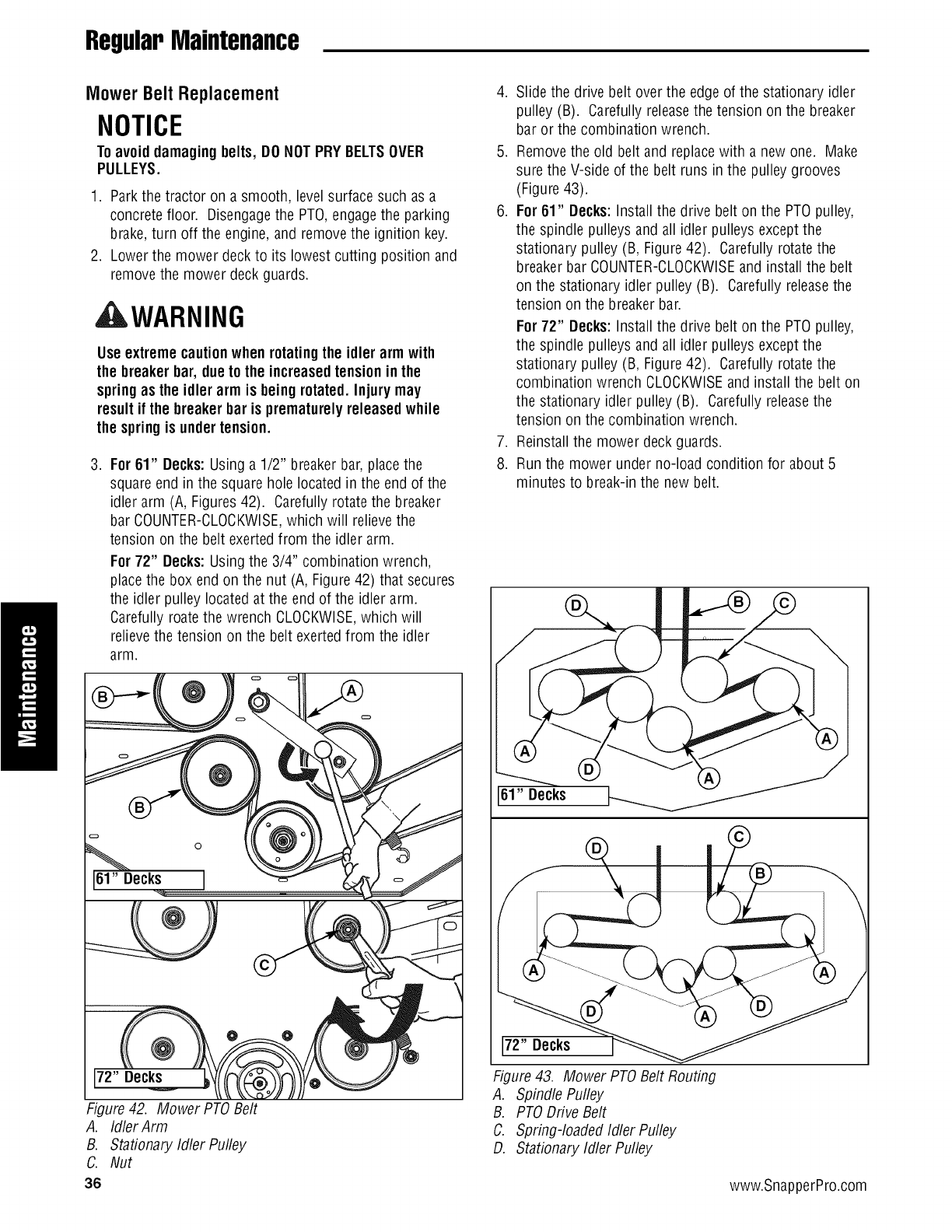
RegularMaintenance
Mower BeltReplacement
NOTICE
Toavoid damauinubelts, DONOTPRY BELTSOVER
PULLEYS.
1. Park the tractor on a smooth, level surface such as a
concrete floor. Disengagethe PTO,engagethe parking
brake,turn off the engine, and remove the ignition key.
2. Lower the mower deckto its lowest cutting position and
removethe mower deck guards.
, WARNING
Use extreme cautionwhen rotatingthe idler arm with
the breakerbar, dueto the increasedtensionin the
springas the idler arm is being rotated.Injury may
result if the breaker bar is prematurely releasedwhile
the springis undertension.
.For 61" Decks:Using a 1/2" breaker bar, place the
square end in the square hole located in the end of the
idler arm (A, Figures42). Carefully rotate the breaker
bar COUNTER-CLOCKWISE,which will relievethe
tension on the belt exertedfrom the idler arm.
For 72" Decks:Using the 3/4" combination wrench,
place the box end on the nut (A, Figure 42) that secures
the idler pulley locatedat the end of the idler arm.
Carefully roate the wrench CLOCKWISE,which will
relieve the tension on the belt exerted from the idler
arm.
Figure 42. Mower PTOBelt
A. Idler Arm
B. Stationary Idler Pulley
C. Nut
36
4. Slide the drive belt over the edge of the stationary idler
pulley (B). Carefully releasethe tension on the breaker
bar or the combination wrench.
5. Removethe old belt and replace with a new one. Make
sure the V-side of the belt runs in the pulley grooves
(Figure 43).
6. For 61" Decks:Install the drive belt on the PTO pulley,
the spindle pulleys and all idlerpulleys except the
stationary pulley (B, Figure42). Carefully rotatethe
breaker bar COUNTER-CLOCKWISEand install the belt
on the stationary idler pulley (B). Carefully releasethe
tension on the breaker bar.
For72" Decks:Install the drive belt on the PTO pulley,
the spindle pulleys and all idlerpulleys except the
stationary pulley (B, Figure42). Carefully rotatethe
combination wrench CLOCKWISEand install the belt on
the stationary idler pulley (B). Carefully releasethe
tension on the combination wrench.
7. Reinstall the mower deck guards.
8. Run the mower under no-load condition for about 5
minutes to break-in the new belt.
/
Figure 43. Mower PTOBelt Routing
A. Spindle Pufley
B. PTO Drive Belt
C. Spring-loaded Idler Pulley
D. Stationary Idler Pulley
www.SnapperPro.com

RegularMaintenance
Hydraulic Pump Drive Belt Replacement
1. Park the tractor on a smooth, level surface such as a
concrete floor. Disengagethe PTO,engagethe parking
brake,turn off the engine, and remove the ignition key.
2. Removethe PTOdrive belt (see MOWERBELT
REPLACEMENTfor removal instructions).
3. Removethe hardware that securesthe clutch anchor
padto the PTOclutch.
AWARNING
STOREDENERGYDEVICE: Improperrelease of the belt
tensionspringcan result in personalinjury.
Use extreme cautionwhen removingthis spring.
4. Loosen the nut on the spring anchor eyebolt (G, Figure
44) to releasethe majority of the belt tension. Use
caution and removethe nut to completely releasethe
tension.
5. Removethe old belt and replace it with the new one.
Makesure the V-side of the belt runs in the grooves of
the crankshaft pulley and pump pulleys (B & C).
6. Reinstall the spring anchor eyebolt (G) into the anchor
tab and loosely fasten the nut. Adjust the anchor
eyebolt until a measurementof 8-3/8" (21,2 cm) is
achievedfrom the outside if the spring hooks. Tighten
nut.
7. Reinstall the clutch anchor pad to the PTOclutch and
securewith the hardware previously removed.
8. Reinstall the PTOdrive belt.
Figure 44. Hydraulic Pump Drive Belt Replacement
A. Pump Drive Belt
B. Crankshaft Pulley
C. Pump Pulley
D. Idler Pulley
E. Idler Arm
F. Spring
G. Spring Anchor Eyebolt
37

RegularMaintenance
BatteryMaintenance
NOTE. This unit is equipped with a maintenance-freeBClU1
battery.
Cleaning the Batteryand Cables
AWARNING
Be careful whenhandlingthe battery.Avoidspilling
electrolyte. Keepflames andsparksaway fromthe
battery.
Whenremovingorinstallingbatterycables,disconnect
the negativecableFIRSTandreconnectit LAST.If not
donein thisorder,the positiveterminalcanbe shortedto
the frameby a tool.
1. Disconnect the cables from the battery, negative(black)
cable first (B, Figure 45).
2. Cleanthe battery terminals and cable ends with a wire
brush until shiny.
3. Reinstall the battery and reattach the battery cables,
positive (red) cable first (A).
4. Coatthe cable ends and battery terminals with
petroleum jelly or non-conducting grease.
Figure 45. Battery Compartment
A. Positive (÷) Cable& Terminal
B. Negative (-) Cable& Terminal
1
38 www.SnapperPro.com

RegularMaintenance
BatteryService
CheckingBatteryVoltage
AWARNING
Keepopen flames and sparksawayfromthe battery;
the gassescomingfromit are highly explosive.
Ventilate the batterywell duringcharging.
A voltmeter can be used to determine condition of battery.
When engine is off, the voltmeter shows battery voltage,
which should be 12 volts. When engine is running, the
voltmeter shows voltage of charging circuit which normally
is 13 to 14 volts.
A dead battery or one too weakto start the engine may not
mean the battery needsto be replaced.For example, it may
mean that the alternator is not charging the battery properly.
If there is any doubt about the causeof the problem, see
your dealer.If you needto replacethe battery,follow the
steps under Cleaningthe Battery & Cablesin the Regular
Maintenance Section.
Charginga CompletelyDischargedBattery
1. Beaware of all the safety precautions you should
observeduring the charging operation. If you are
unfamiliar with the use of a battery charger and
hydrometer, havethe battery serviced by your dealer.
2. Add distilled water sufficient to cover the plate (fill to the
proper level nearthe end of the charge). If the battery is
extremely cold, allow it to warm before adding water
becausethe water level will rise as it warms. Also, an
extremely cold battery will not accept a normal charge
until it becomes warm.
3. Always unplug or turn the charger off before attaching
or removing the clamp connections.
4. Carefully attachthe clamps to the battery in proper
polarity (usually red to [+] positive and black to [-]
negative).
5. While charging, periodically measurethe temperature of
the electrolyte. If the temperature exceeds 125° F (51.6°
C), or if violent gassing or spewing of electrolyte occurs,
the charging rate must be reduced or temporarily halted
to prevent battery damage.
6. Chargethe battery until fully charged (until the specific
gravity of the electrolyte is 1.250 or higher and the
electrolyte temperature is at least 60° F).The best
method of making certain a battery is fully charged, but
not over charged, is to measurethe specific gravity of a
cell once per hour. The battery is fully charged when the
cells are gassing freely at low charging rate and less
than 0.003 change in specific gravity occurs over a three
hour period.
JumpStartingWith Auxiliary (Booster)Battery
Jump starting is not recommended. However,if it must be
done, follow these directions. Both booster and dis-charged
batteries should be treated carefully when using jumper
cables. Followthe steps below EXACTLY,being careful not to
cause sparks. Referto Figure46.
1. Both batteries must be of the samevoltage.
2. Position the vehicle with the booster battery adjacentto
the vehicle with the discharged battery so that booster
cables can be connected easily to the batteries in both
vehicles. Makecertain vehicles do not touch each other.
3. Wear safety glasses and shield eyes andface from
batteries at all times. Besure vent caps aretight. Place
damp cloth over vent caps on both batteries.
4. Connect positive (+) cable to positive post of discharged
battery (wired to starter or solenoid).
5. Connectthe other end of same cable to same post
marked positive (+) on booster battery.
6. Connectthe second cable negative (-) to other post of
booster battery.
7. Makefinal connection on engine block of stalled vehicle
away from battery. Do not leanover batteries.
8. Start the engine of the vehicle with the booster battery.
Wait a few minutes, then attempt to start the engine of
the vehicle with the discharged battery.
9. If the vehicle does not start after cranking for thirty
seconds, STOPPROCEDURE.More than thirty seconds
seldom starts the engine unless some mechanical
adjustment is made.
10. After starting, allow the engineto return to idle speed.
Removethe cable connection at the engineor frame.
Then remove the other end of the same cable from the
booster battery.
11. Removethe other cable by disconnecting at the
discharged battery first and then disconnect the
opposite end from the booster battery.
12. Discard the damp cloths that were placed over the
battery vent caps.
39

RegularMaintenance
THIS HOOK-UP FOR NEGATIVE GROUND VEHICLES
To
Starter
Switch "__ Jumper Cable
Starting l-_ '__
Vehicle
Battery
To Ground
To
Starter
Switch
Discharged
Vehicle
@Battery
Engine
Block
MAKE CERTAIN VEHICLES DO NOT TOUCH
Figure 46. Jump Starting
WARNING
Anyprocedure other thanthe preceding couldresult in:
(1) personal injurycausedbyelectrolytesquirting
outthe batteryvents,
(2) personal injuryor propertydamage dueto
batteryexplosion,
(3) damageto the chargingsystemof the booster
vehicle or of the immobilizedvehicle.
Do notattempt tojump start a vehiclehavinga frozen
batterybecausethe batterymay ruptureorexplode. If
a frozenbatteryis suspected,examineall fill vents on
the battery. If icecanbe seen or if the electrolytefluid
cannotbe seen, donotattempt to start with jumper
cablesas long asthe batteryremainsfrozen.
WARNING
Foryour personal safety, use extreme care whenjump
starting. Neverexposebatteryto openflame orelectric
spark- batteryaction generateshydrogengas which is
flammable andexplosive. Do not allow batteryacid to
contactskin, eyes, fabrics, or paintedsurfaces.
Batteriescontaina sulfuricacid solutionwhich can
cause seriouspersonalinjury or propertydamage.
When removingor installing batterycables, disconnect
the negativecable FIRSTandreconnectit LAST.If not
done in thisorder, the positiveterminal can be shorted
to the frame by a tool.
Toavoid enginedamage, donotdisconnectbattery
while engineis running.Be sureterminal connections
are tight before starting.
40 www.SnapperPro.com

RegularMaintenance
Storage
TemporaryStorage(30 DaysOr Less)
Remember,the fuel tank will still contain some gasoline, so
never store the unit indoors or in any other area where fuel
vapor could travel to any ignition source. Fuelvapor is also
toxic if inhaled, so never store the unit in any structure used
for human or animal habitation.
Here is a checklist of things to do when storing your unit
temporarily or in between uses:
• Keepthe unit in an areaawayfrom where children may
come into contact with it. If there's any chanceof
unauthorized use, removethe spark plug (s) and put in a
safe place. Besure the spark plug opening is protected
from foreign objects with a suitable cover.
• If the unit can't be stored on a reasonable levelsurface,
chock the wheels.
• Cleanall grass and dirt from the mower.
LongTermStorage(LongerThan 30 Days)
Before you store your unit for the off-season, readthe
Maintenance and Storage instructions in the Safety Rules
section, then perform the following steps:
1. Drain crankcase oil while engine is hot and refill with a
grade of oil that will be requiredwhen unit is used again.
2. Preparethe mower deckfor storage as follows:
a. Removemowerdeckfrom the unit.
b. Cleanundersideof mowerdeck.
c. Coatall baremetalsurfaceswith paint or light coat of
oil to preventrusting.
3. Cleanexternal surfaces and engine.
4. Prepareenginefor storage. Seeengine owner's
manual.
5. Cleanany dirt or grass from cylinder headcooling fins,
engine housing and air cleaner element.
6. Coverair cleaner and exhaust outlet tightly with plastic
or other waterproof material to keepout moisture, dirt
and insects.
7. Completelygrease and oil unit as outlined in the Normal
Caresection.
8. Cleanup unit and apply paint or rust preventativeto any
areaswhere paint is chipped or damaged.
9. Besure the battery is filled to the proper level with water
and is fully charged. Battery life will be increasedif it is
removed, put in a cool, dry place and fully charged
about once a month. If battery is left in unit, disconnect
the negativecable.
AWARNING
Neverstorethe unit, with gasoline in engineor fuel
tank, in aheatedshelter or in enclosed, poorly
ventilatedenclosures.Gasolinefumes may reachan
openflame, sparkor pilot light(suchas a furnace,
water heater, clothesdryer,etc.) and causean
explosion.
Handlegasoline carefully. It is highlyflammable and
carelessuse couldresult in seriousfire damageto
yourpersonor property.
Drainfuel into an approvedcontaineroutdoorsaway
from openflame or sparks.
10. Drain fuel system completely or add a gasoline stabilizer
to the fuel system. If you have chosen to use a fuel
stabilizer and have not drained the fuel system, follow all
safety instructions and storage precautions in this
manual to prevent the possibility of fire from the ignition
of gasoline fumes. Remember,gasoline fumes can travel
to distant sources of ignition and ignite, causing risk of
explosion and fire.
NOTE.Gasoline,if permitted to stand unused for extended
periods (30 days or more), may develop gummy deposits
which can adversely affect the engine carburetor and cause
enginemalfunction. Toavoid this condition, add a gasoline
stabilizer to the fuel tank and run the engine a few minutes,
or drain aft fuel from the unit before placing it in storage.
Starting After Long Term Storage
Beforestarting the unit after it has beenstored for a long
period of time, perform the following steps.
1. Removeany blocks from under the unit.
2. Install the battery if it was removed.
3. Unplug the exhaust outlet and air cleaner.
4. Fill the fuel tank with fresh gasoline. Seeengine
manual for recommendations.
5. See engine owner's manual and follow all instructions
for preparing engine after storage.
6. Checkcrankcaseoil level and add proper oil if
necessary.If any condensationhas developedduring
storage, drain crankcaseoil and refill.
7. Inflate tires to proper pressure. Checkfluid levels.
8. Start the engine and let it run slowly. DO NOTrun at
high speed immediately after starting. Be sure to run
engine only outdoors or in well ventilated area.
41

Troubleshooting
Troubleshooting
Troubleshooting Chart
While normal care and regular maintenancewill extend the
life of your equipment, prolonged or constant use may
eventually requirethat service be performed to allow it to
continue operating properly.
The troubleshooting guide below lists the most common
problems, their causes and remedies.
Seethe information on the following pages for instructions
on how to perform most of these minor adjustments and
service repairs yourself. If you prefer, all of these
procedures can be performed for you by your local
authorized dealer.
,AWARNING
Toavoid seriousinjury, perform maintenanceonthe
tractoror moweronly whenthe engineis stoppedand
the parking brakeengaged.
Alwaysremovethe ignition key, disconnectthe spark
plugwire andfasten it awayfrom the plug before
beginningthe maintenance,to preventaccidental
startingof the engine.
Troubleshooting the Rider
Problem
Enginewill notturnover or start.
Cause
1. Parking brake not engaged.
2. PTO (electric clutch) switch
in ON position.
3. Out of fuel.
.
5.
6.
Engineflooded.
Fuseblown.
Battery terminals require
cleaning.
Battery discharged or dead.
Wiring loose or broken.
Remedy
1. Engageparkingbrake.
2. Placein OFFposition.
3. If engine is hot, allow it to cool, then refill
the fuel tank.
4. Move choke control to closed position.
5. Replacefuse.
6. Cleanthe battery terminals
7. 7. Rechargeor replace.
8. 8. Visually check wiring & replace broken or
frayed wires. Tighten loose connections.
9. Solenoid or starter motor faulty. 9. Repair or replace. See authorized dealer
10. Safety interlock switch 10. Replaceas needed.Seeauthorized
faulty, service dealer.
11. Spark plug(s) faulty, fouled 11. Cleanand gap or replace.
or incorrectly gapped. See engine manual.
12. Water in fuel. 12. Drain fuel & replace with fresh fuel.
13. Gas is old or stale. 13. Drain fuel & replace with fresh fuel.
Enginestartshard or runs poorly. 1. Fuel mixture too rich. 1. Clean air filter. Check choke adjustment.
2. Spark plug faulty, fouled, or 2. Cleanand gap or replace.
incorrectly gapped. (Seeengine manual.)
Engineknocks. 1. Low oil level. 1. Check!add oil as required.
2. Using wrong grade oil. 2. See engine manual.
Excessiveoil consumption. 1. Engine running too hot. 1. Cleanengine fins, blower screen and
air cleaner.
2. Using wrong weight oil. 2. See engine manual.
3. Too much oil in crankcase. 3. Drain excessoil.
Engineexhaustis black. 1. Dirty air filter. 1. Replaceair filter. See engine manual.
2. Engine choke control 2. Open choke control.
is in closed position.
42 www.SnapperPro.com

Troubleshooting
Rider TroubleshootingContinued.
Problem
Engineruns,but riderwill
notdrive.
Cause
1. Hydraulic releasevalve(s)
Remedy
1. Turnvalve(s)clockwiseto close.
in "open" position.
2. Belt is broken. 2.
3. Drive belt slips. 3.
4. Brake is not fully released. 4.
Rider drive belt slips. 1. Pulleys or belt greasy or oily. 1
2. Tensiontoo loose• 2.
3. Belt stretched or worn. 3.
Brakewill not hold. 1. Brake is incorrectly adjusted. 1
2. Brake pads worn. 2.
Rider steers or handlespoorly. 1. Steering linkage is loose. 1
2. Improper tire inflation. 2.
See Drive Belt Replacement•
See problem and cause below.
Seeauthorized service dealer
•Cleanas required•
Adjust spring tension•
See Drive Belt Replacement
Replacebelt.
•See BrakeAdjustment•
Replacewith new brake pads.
• Check and tighten any loose connections.
See Regular Maintenance Section.
Troubleshootingthe Mower
Problem Cause
Mower will not raise. 1. Lift linkage not properly attached
or damaged.
Enginestalls easily with 1. Enginespeed too slow. 1.
mower engaged. 2. Ground speed too fast. 2.
3. Cutting height set too low. 3.
Excessivemowervibration.
4. Discharge chute jamming 4.
with cut grass.
1. Blade mounting bolts are loose• 1.
2. Mower blades, arbors, 2.
or pulleys are bent.
3. Mower blades are out 3.
of balance.
4. Belt installed incorrectly• 4.
Excessivebelt wear or breakage. 1. Bent or rough pulleys. 1.
2. Using incorrect belt• 2.
Mower drive belt slips 1. Idler pulley spring broken or not 1.
or fails to drive, properly attached.
2. Mower drive belt broken. 2.
Mower does not engage. 1. Electrical wiring damage. 1.
2• PTOclutch not adjusted 2•
3. Battery voltage too low. 3.
Remedy
1. Seeauthorizedservicedealerfor repair.
Set to full throttle.
DecreaseGround Speed.
Cut tall grass at maximum cutting
height during first pass.
Cut grass with discharge pointing toward
previously cut area.
Tighten to 70 ft.lbs. (94 N.m.).
Check and replaceas necessary•
Remove,sharpen, and balanceblades.
See MaintenanceSection.
Reinstall Correctly•
Repair or replace•
Replacewith correct belt.
Repair or replaceas needed.
Replacedrive belt.
Locate& repair damagedwire.
See PTOClutch Adjustment section
Rechargebattery and checkalternator.
See Battery Maintenance section.
43

Troubleshooting
Troubleshooting Common Cutting
Problem
Streaking.
Scalping.
Problems
Cause
1. Blades are not sharp.
2. Blades are worn down to far.
3. Engine speed is too slow.
4. Ground speed is too fast.
5. Deck is plugged with grass
6. Not overlapping cutting rows
enough.
7. Not overlapping enough when
turning.
1. Lawn is uneven or bumpy.
2. Mower deck cutting height is
set too low.
3. Ground speed is too fast.
4. Deck is not leveledcorrectly.
5. Tire pressure is low or uneven
Remedy
1. Sharpenyour blades.
2. Replaceyour blades.
3. Always mow at full throttle.
4. Slow down.
5. Cleanout the mower.
6. Overlapyour cutting rows.
7. When turning your effective cutting width
decreases-overlap more when turning.
1. Roll or level the lawn.
2. Raisethe cutting height.
3. Slow down.
4. Correctly level the deck.
5. Check and inflate the tires.
SteppedCutting. 1. Deck is not leveledcorrectly.
2. Tires are not properly inflated.
3. Blades are damaged.
4. Deck shell is damaged.
5. Mower spindle is bent or loose.
6. Blades are installed incorrectly.
1. Levelthe deck correctly.
2. Check and inflate the tires.
3. Replacethe blades.
4. Repair or replacethe deck.
5. Repair or replacethe spindle.
6. Reinstall the blades correctly.
UnevenCutting.
Stingers.
1. Deck is not leveledcorrectly.
2. Blades are dull or worn.
3. Blades are damaged.
4. Deck is clogged with grass
clippings.
5. Deck shell is damaged.
6. Mower spindle is bent or loose.
7. Blades are installed incorrectly.
8. Tires are not properly inflated.
1. Blades are not sharp or nicked.
2. Blades are worn down too far.
3. Engine speed is too slow.
4. Ground speed is too fast.
5. Deck is plugged with grass.
1. Levelthe deck correctly.
2. Sharpen or replace the blades.
3. Replacethe blades.
4. Cleanout the deck.
5. Repair or replacethe deck.
6. Repair or replacethe spindle.
7. Reinstall the blades correctly.
8. Check and inflate the tires.
1. Sharpen your blades.
2. Replaceyour blades.
3. Always mow at full throttle.
4. Slow down.
5. Cleanout the mower.
44 www.SnapperPro.com

Specifications
Specifications
NOTE.Specifications are correct at time of printing and are subject to changewithout notice.
*Actual sustained equipment horsepower will likely be lower due to operatingfimitations and environmental factors.
ENGINE:
25 HP Kawasaki
Make Kawasaki
Model FH721V
Horsepower 25 @3600 rpm
Displacement 41.2 Cu. in (675 cc)
Electrical System 12 Volt, 13 amp. Alternator, Battery: 340 CCA
Oil Capacity 2.0 US qt. ( 1.9 L) w/Filter
27 HP Kohler
Make Kohler
Model CV740S
Horsepower 27 @3600 rpm
Displacement 44.24 Cu. in (725 cc)
Electrical System 12 Volt, 16 amp. Alternator, Battery: 340 CCA
Oil Capacity 2.1 US qt.. (2.0 L) w/Filter
27 HP Kawasaki
Make Kawasaki
Model FX751V
Horsepower 27 @3600 rpm
Displacement 52.0 Cu. in (852 cc)
Electrical System 12 Volt, 15 amp. Alternator, Battery: 340 CCA
Oil Capacity 2.0 US qt. ( 1.9 L) w/Filter
32 HP Briggs & Stratton
Make Briggs & Stratton
Model 543777-0120-E1
Horsepower 32 @3600 rpm
Displacement 54.62 Cu. in (895 cc)
Electrical System 12 Volt, 20 amp. Alternator, Battery: 340 CCA
Oil Capacity 2.4 US qt.. (2.25 L) w/Filter
CHASSIS:
Fuel Tank
Rear Wheels
FrontWheels
Capacity: 12 Gallons (45.4 L)
Tire Size: 24 x 12.00 -12
Inflation Pressure: 15 psi (1,03 bar)
Tire Size: 13 x 6.50 - 6
Inflation Pressure: 25 psi (1,72 bar)
TRANSMMISSIONS:
HydroGear PG-3H /HGIVI-12E3131
Type
HydraulicFluid
Speeds
@ 3400 rpm
ContinuousTorque
Output
Maximum Weight
on Axle
Pump and Wheel Motor
SAE20W-50 motor oil
Forward: 0-10 MPH (0-16.09 km/h)
Reverse:0-5 MPH (0-8.05 km/h)
222 ft. Ibs. (301 N.m.)
750 Ibs. (340 Kg)
EnginePower Rating Information
The gross power rating for individual gas engine models is labeledin accordancewith SAE(Society of Automotive Engineers)
code J1940 (Small Engine Power & Torque Rating Procedure), and rating performance has been obtained and corrected in
accordancewith SAEJ1995 (Revision 2002-05). Torque valuesare derived at 3060 RPM; horsepower values are derived at
3600 RPIVI.Actual gross engine power will be lower and is affected by, among other things, ambient operating conditions and
engine-to-engine variability. Given both the wide array of products on which engines are placed and the variety of
environmental issues applicableto operating the equipment, the gas enginewill not develop the ratedgross power when used
in a given piece of power equipment (actual "on-site" or net power). This difference is due to a variety of factors including, but
not limited to, accessories (air cleaner,exhaust,charging, cooling, carburetor, fuel pump, etc.), application limitations,
ambient operating conditions (temperature, humidity, altitude), and engine-to-engine variability. Due to manufacturing and
capacity limitations, Briggs & Stratton may substitute an engine of higher rated powerfor this Series engine.
45

Ferris Industries - a division of Simplicity Manufacturing Inc.
Owner's Limited Warranty Information
(Effective 04/28/2004)
Thank you for purchasing Ferris commercial mowing equipment. Please take a few minutes to read this limited warranty information. It contains all
the information you will need to have your Ferris mower repaired in the unlikely event that a breakdown covered by this limited warranty should occur.
Owner's Responsibilities - As a condition to our obligations under this limited warranty, you shall have read the operator's manual and you shall have
completed and submitted to Ferris, within 20 days from the date of purchase, the Ferris Product Registration. You must properly service and maintain
your Ferris product as described in the operator's manual. Such routine maintenance, whether performed by a dealer or by you, is at your expense.
The Ferris equipment, including any defective part covered by this limited warranty, must be returned to an authorized Ferris dealer within the warranty
period for warranty service. This limited warranty extends only to equipment operated under normal conditions and in accordance with Ferris' instruc-
tions.
Warranty Start Date - The limited warranty coverage begins on the day you buy your new Ferris commercial mowing equipment. An authorized Ferris
dealer will assist you in filling out a Ferris Product Registration with specific information for the model you purchase and your personal information,
which must be returned to Ferris.
Limited Warranty - The limited warranty, set forth below, is a written guarantee by Ferris, during the warranty period, to repair or replace parts which
have a substantial defect in materials or workmanship. The warranty is "limited" because it is for a specified period of time, applies to the original pur-
chaser only, and is subject to other restrictions.
FERRIS LIMITEDWARRANTY
Ferris Industries (Ferris) warrants, in accordance with the provisions below, to the original purchaser only, for the periods described below that the
commercial mower shall be free from substantial defects in material or workmanship under normal use and service. If you wish to file a claim under
this limited warranty, you must provide prompt notice of your claim to an authorized Ferris dealer during the warranty period. Ferris' obligation under
this limited warranty is, at Ferris' option, to repair or replace any part or parts of the mower, which, in the judgment of Ferris, are found to be defective
and covered by this limited warranty. An authorized Ferris dealer will repair or replace the defective part or parts, at the dealer's place of business, at
no charge for the labor or parts. This limited warranty applies only to mowers sold in the United States and Canada and is subject to the following limi-
tations.
Covered Parts
All Mowers
*Belts, Tires, Brake Pads
And Hoses, Battery, Blades
*Attachments
*Engine
Warranty Period
2-years (24 months) from date of retail purchase by the original
purchaser for parts & labor (90 days for rental mowers)
(Except as noted below*)
90 days from date of retail purchase by the original purchaser
1 year from date of retail purchase by the original purchaser
If the engine manufacturer provides any warranty on the mower's engine, Ferris will assign that warranty to the
original purchaser of the mower if such assignment is reasonably practicable. Please refer to the engine man-
ufacturer's warranty statement, if any, that is included in the owner's packet. We are not authorized to handle
warranty adjustments or repairs on engines. Ferris offers NO WARRANTY on mower engines. Ferris does not
guarantee or represent that any engine manufacturer will comply with the terms of its warranty.
Items and Conditions Not Covered
This warranty does not cover, and Ferris makes NO WARRANTY regarding, the following:
•Mowers or their parts if a complete and accurate Ferris Product Registration has not been received by Ferris.
• Loss or damage to person or property other than that expressly covered by the terms of this limited warranty.
• Pickup and delivery charges and risk of loss or damage in transit to and from any authorized Ferris dealer.
• Any damage or deterioration due to normal use, wear and tear, or environmental or natural elements, or exposure.
• Cost of regular maintenance service or parts, such as but not limited to, filters, fuel, lubricants, tune-up parts, and adjustments.
• Claims arising due to failure to follow Ferris' written instructions, or improper storage or maintenance.
• Any repairs necessary due to use of parts, accessories or supplies, including gasoline, oil or lubricants, incompatible with the mowing equipment,
or other than as recommended in the operator's manual or other written operational instructions provided by Ferris.
• Use of non-Ferris approved parts or accessories.
• Any overtime or other extraordinary repair charges or charges relating to repairs or replacements.
• Rental of like or similar replacement equipment during the period of any warranty, repair or replacement work.
• Loss of revenue, time or use of the mowing equipment.
• Travel, telephone or other communication charges.
• Damage from continued use of defective mowing equipment.
• Freight charges on replacement parts.
• Any mowing equipment or part which, in the judgment of Ferris, has been altered or tampered with in any way or has been subjected to misuse,
abuse, abnormal usage, unauthorized repair, neglect or accident, damage in transit, or has had the serial numbers altered, effaced or removed.
• Any equipment, part or item not mentioned under "Covered Parts," above.
General Conditions
Ferris is continually striving to improve its products, and therefore reserves the right to make improvements or changes without incurring any obligation
to make changes or additions to products sold previously. Any oral or written description of Ferris products is for the sole purpose of identifying the
products and shall not be construed as an express warranty. No warranty claim shall give rise to a right for the purchaser to cancel or rescind any
sale. No person is authorized to make any warranty or assume for Ferris any liability not strictly in accordance with this limited warranty. Any assis-
tance Ferris provides to or procures for the purchaser outside the terms, limitations or exclusions of this limited warranty will not constitute a waiver of
the terms, limitations or exclusions of this limited warranty, nor will such assistance extend or revive the limited warranty. Ferris will not reimburse the
purchaser for any expenses incurred by the purchaser in repairing, correcting or replacing any defective products except for those incurred with Ferris'
prior written permission and in accordance with this limited warranty.
Ferris' sole and exclusive liability with respect to this limited warranty, and the purchaser's exclusive remedy, shall be repair or replacement as set forth
herein. All warranty work must be performed by an authorized Ferris dealer using only Ferris approved replacement parts. FERRIS SHALL HAVE NO
LIABILITY FOR ANY OTHER COST, LOSS OR DAMAGE, INCLUDING BUT NOT LIMITED TO, ANY INCIDENTAL, COMPENSATORY, INDIRECT,
PUNITIVE, SPECIAL OR CONSEQUENTIAL LOSS OR DAMAGE. FERRIS' AGGREGATE LIABILITY WITH RESPECT TO A DEFECTIVE PROD-
UCT OR PART SHALL BE LIMITED TO AN AMOUNT EQUAL TO THE MONIES PAID BY THE PURCHASER FOR THAT DEFECTIVE PRODUCT
OR PART. THIS LIMITED WARRANTY, AND FERRIS' OBLIGATIONS HEREUNDER, ARE EXCLUSIVE AND IN LIEU OF ALL OTHER WAR-
RANTIES, EXPRESS OR IMPLIED, INCLUDING, WITHOUT LIMITATION, THE IMPLIED WARRANTY OF MERCHANTABILITY AND THE IMPLIED
WARRANTY OF FITNESS FOR A PARTICULAR PURPOSE. FERRIS SHALL NOT BE LIABLE TO THE PURCHASER, OR TO ANYONE CLAIMING
UNDER THE PURCHASER, FOR ANY OTHER OBLIGATIONS OR LIABILITIES, INCLUDING, BUT NOT LIMITED TO, OBLIGATIONS OR LIABILI-
TIES ARISING OUT OF BREACH OF CONTRACT OR WARRANTY, NEGLIGENCE OR OTHER TORT OR ANY THEORY OF STRICT LIABILITY,
WITH RESPECT TO FERRIS PRODUCTS OR FERRIS' ACTS OR OMISSIONS OR OTHERWISE.
It is the express wish of the parties that this agreement and any related documents be drafted in English. II est la volonte expresse des parties que
cette convention et tousles documents s'y rattachent soient rediges en anglais.

MANUAL
S200XSeries
Zero-TurnRiding
'S
ProductSpecifications: CommonService Parts:
ENGINE:
25 HPKawasaki
Make Kawasaki
Model FH721V
Oil Capacity 2.0 US pt. ( 1.9 L) w/Filter
27 HPKohier
Make Kohler
Model CV740S
Oil Capacity 2.2 pt. (2.0 L) w/Filter
27 HPKawasaki
Make Kawasaki
Model FX751V
Oil Capacity 2.0 US pt. ( 1.9 L) w/Filter
32 HP Briggs & Stratton
Make Briggs & Stratton
Model 543777-0120-E1
Oil Capacity 2.4 pt. (2.25 L) w/Filter
CHASSIS:
Fuel Tank
Rear Wheels
Front Wheels
Capacity: 12 Gallons (45.4 L)
Tire Size: 24 x 12.00 -12
Inflation Pressure: 15 psi (I ,03 bar)
Tire Size: 13 x 6.50 -6
Inflation Pressure: 25 psi (I ,72 bar)
BELTSAND BLADES:
TRACTOR
Pump Drive Belt 5101029
61" MOWER DECK
Deck Drive Belt 5100893
Mower Blade 5020842
72" MOWER DECK
Deck Drive Belt 5022399
Mower Blade 5022476
Briggs & Stratton Yard PowerProductsGroup
5375 North Main Street
Munnsville, NY 13409
800-933-6175
www.SnapperPro.com
