SORIN CRM KA961 SMARTVIEW MONITOR User Manual 2
SORIN CRM SMARTVIEW MONITOR 2
Contents
- 1. User manual 2
- 2. User manual 2 GPRS
User manual 2
User's manual
KA961
–
Wireless
model
blank

ENGLISH – 1
TABLE OF CONTENTS
1.Introduction ................................................................................. 6
2.Indication ..................................................................................... 6
3.Warnings and precautions ........................................................ 7
3.1.Warnings ........................................................................... 7
3.2.Safety precautions ........................................................... 7
3.3.Precautions for safe operation ....................................... 8
4.Familiarise yourself with your SMARTVIEW monitor ............. 9
4.1.Package contents ............................................................. 9
4.2.Description ........................................................................ 10
4.3.Meaning of the lights and buttons .................................. 11
5.Using your SMARTVIEW monitor ............................................. 12
5.1.Setting-up your SMARTVIEW monitor ........................... 12
5.2.Complete the installation with communication
setup .................................................................................. 13
5.3.Operational usage ............................................................ 13
5.4.Patient Initiated Transfer operation ................................ 14
6.Travelling ..................................................................................... 14
7.Moving home ............................................................................... 14
8.SMARTVIEW monitor basic care ............................................... 14
9.Maintenance and Recycling ...................................................... 15
10.FAQ .............................................................................................. 15
11.Technical specifications ............................................................ 16
12.Data protection ........................................................................... 17
13.Declaration of conformity .......................................................... 17

2 – ENGLISH
14.Guidance and manufacturer’s declaration .............................. 21
14.1.Electromagnetic emissions ............................................. 21
14.2.Electromagnetic immunity .............................................. 22
14.3.Recommended separation distances between
portable and mobile RF communications
equipment and the SMARTVIEW monitor ...................... 25
15.Technical assistance .................................................................... 26
ENGLISH – 3
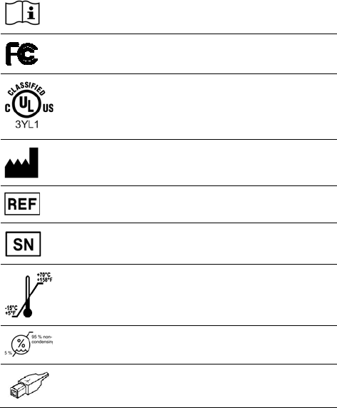
LIST OF SYMBOLS
This symbol is used to encourage you to consult the documentation and
manual enclosed in the packaging.
This symbol confers the approval of the US Federal Communications
Commission.
This symbol indicates that the device meets UL requirements.
Remote Cardiac Monitor (Medical Equipment) WITH RESPECT TO ELECTRIC
SHOCK, FIRE AND MECHANICAL HAZARDS ONLY IN ACCORDANCE WITH
IEC 60601-1, CAN/CSA 60601-1, ANSI/AAMI ES 60601-1.
Name and address of the manufacturer.
Sorin Reference of the SMARTVIEW monitor
Serial number
Temperature limits for storage and transportation
Humidity limits for storage and transportation
USB Type B Power supply connector at SMARTVIEW Monitor level

4 – ENGLISH
Ref. P601006
Use only power block ref. P601006 with your monitor
The monitor shall be powered only with direct current. The power block
packaged with your monitor fulfils this requirement.
This electronic product is subject to disposal and recycling regulations that vary
by country and region.
Many countries prohibit the disposal of waste electronic equipment in standard
waste receptacles. For more details, please refer to the European Directive
2002/96/CEE.
Keep the device dry – Keep it away from liquid and do not spill or drip water on it.
ENGLISH – 5
SYMBOLS USED IN THIS MANUAL
This icon is used to call your attention to a
particularly important point.
This icon alerts you to a hazard that may result in
equipment damage or personal injury. Carefully
read the instructions provided with this icon.
ABOUT THIS MANUAL
Your doctor should be your first source of information regarding your health.
This manual addresses many of the questions you or your family may
have about your SMARTVIEW monitor and its use.
If you have technical or usage questions that are not covered in this manual
or you want more in-depth information, please contact the Sorin toll-free
technical assistance.

6 – ENGLISH
1. INTRODUCTION
The SMARTVIEW monitor you received is part of the SMARTVIEW Remote
Monitoring System. This system has been specially designed to transmit
information stored in your Sorin implanted cardiac device to your doctor on a
regular basis. Your Sorin cardiac device is equipped with a transmitter which
sends clinical information and device parameters to your doctor through the
SMARTVIEW monitor using Radio Frequency wireless technology. The data
retrieved by your SMARTVIEW monitor is routed through the cellular
network, converted to a format that can be reported to your doctor.
The SMARTVIEW Remote Monitoring System designed by Sorin is a
fully automated system which does not need any specific interaction in
operational mode. It can, however, also be used manually but only on
your doctor’s instruction.
2. INDICATION
The SMARTVIEW monitor is designed for use with the Sorin radio
frequency implanted cardiac device only.

ENGLISH – 7
3. WARNINGS AND PRECAUTIONS
3.1. WARNINGS
If at any time you feel that you need a fast response,
CALL YOUR LOCAL EMERGENCY SERVICE
IMMEDIATELY.
The SMARTVIEW Remote Monitoring System is not
intended as an emergency response system.
3.2. SAFETY PRECAUTIONS
Alteration – Your SMARTVIEW monitor and supplied accessories shall
not be modified, altered, or changed in any way without signed written
permission from Sorin. Unauthorized modification may void the
equipment authorization from the FCC and will void the Sorin warranty.
Use only Sorin supplied accessories.
Keep Children Away – Do not let children touch the SMARTVIEW
monitor.
Environmental factors – To reduce the risk of fire, electric shock and
personal injury, do not expose this appliance to rain, moisture or
extreme temperatures and avoid any installation or Patient Initiated
Transfer operation during an electrical storm. If the SMARTVIEW
monitor is damaged due to a shock or liquid exposure, do not plug it in
again and call our toll-free technical assistance.
Keep dry the device – Keep it away from liquid and do not spill or drip
water on it.
8 – ENGLISH
3.3. PRECAUTIONS FOR SAFE OPERATION
Location – Preferably the SMARTVIEW monitor should be placed in a
stable position on the nightstand of the patient, as close as possible to
the side of the bed the patient usually sleeps.
Power supply – The SMARTVIEW monitor should be connected
exclusively to a Sorin power adaptor.
Power supply protection – Power adaptors should be routed so they are
not likely to be walked on or pinched by items placed on or against them.
Power supply disconnection – The power socket must be near the
SMARTVIEW monitor and easily accessible. You can only remove power
from the SMARTVIEW monitor by disconnecting the power adaptor from the
outlet. Always carefully disconnect all plugs by pulling on the plug and
not on the cord.
Wireless communication – The SMARTVIEW monitor is designed for
use with cellular network. It is intended to transmit your personal data
using a cell phone operator. The operator and number to call are pre-
configured, there is nothing to tune.
Check button – Do not press the Check button on the bottom of the
monitor unless requested to do so by our toll-free technical assistance.
Interferences – The SMARTVIEW monitor can be influenced by other
household appliances (such as alarm clock, mobile phone). If possible, you
should avoid placing electrical appliances next to the SMARTVIEW monitor.
ENGLISH – 9
4. FAMILIARISE YOURSELF WITH YOUR
SMARTVIEW MONITOR
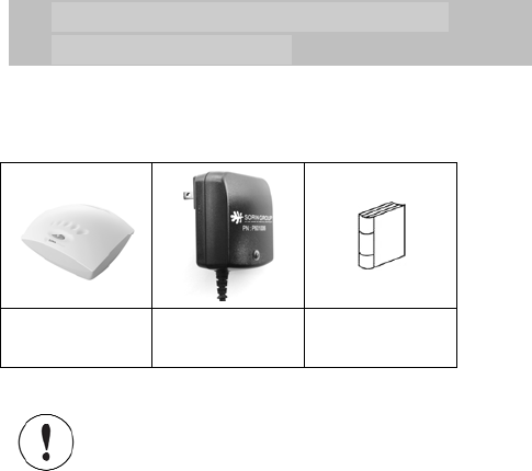
4.1. PACKAGE CONTENTS
Inside the box you will find:
1 SMARTVIEW
monitor 1 Power adaptor User’s manual
Do not use any other parts than the ones supplied with
the SMARTVIEW monitor, as this may result in
increased emissions or decreased immunity of the
equipment.
10 – ENGLISH
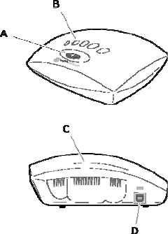
4.2. DESCRIPTION
A/ Patient initiated transfer
button
B/ Progress bar
C/ Status light
D/ Power supply inlet
(cable with the orange mark)

ENGLISH – 11
4.3. MEANING OF THE LIGHTS AND BUTTONS
Light or button State Colour Meaning
Status light OFF No colour The SMARTVIEW monitor is not
plugged in properly. Please check the
connections. If the status light remains
off, please contact our toll-free technical
assistance.
ON Constant
amber You have just connected the
SMARTVIEW monitor to the wall
socket. The SMARTVIEW monitor is
setting up. Please wait. This process
takes less than 5 minutes.
Constant
green The SMARTVIEW monitor is operational.
Patient initiated
transfer button Flashing Green The SMARTVIEW monitor is gathering
data. Stay as close as possible to the
SMARTVIEW monitor and don’t
disconnect it.
Red The SMARTVIEW monitor could not
gather the information stored in your
implanted defibrillator. Move closer to the
SMARTVIEW monitor and restart the
process. If the button turns red again,
please contact our toll-free technical
assistance.
ON Green You pushed the button to request a Patient
Initiated Transfer transmission. The
SMARTVIEW monitor is checking that the
function is active before performing the
transmission.
Progress lights Progress Green The SMARTVIEW monitor is gathering
information from your implanted
defibrillator. Stay as close as possible
to the SMARTVIEW monitor and don’t
disconnect it.

12 – ENGLISH
5. USING YOUR SMARTVIEW MONITOR
The Sorin SMARTVIEW monitor works automatically. Therefore, you will
have no interaction with it except at installation and only on your doctor’s
request.
5.1. SETTING-UP YOUR SMARTVIEW MONITOR
In order to perform the installation of your SMARTVIEW monitor in a quick,
easy and safe way, we recommend you to call our technical assistance (see
toll-free phone numbers at the end of this manual). Our technicians will
assist you. It is free and takes little time.
Step Operation
1 Take all the items out of the box.
2 Place your SMARTVIEW monitor
in a stable position,
preferably on your nightstand, as close as possible to the
side of the bed you usually sleep on.
3 Remove the power adaptor from the little white box and
plug the end of the cable with the orange mark into the
appropriate inlet in the SMARTVIEW monitor identified
with the same orange mark.
4 Plug the power supply
block into
the mains. A green light
turns ON immediately on this block.
5 You should observe the following:
The status light turns stable amber for around 45 seconds
and then turns green. Your SMARTVIEW monitor is now
ready for the next step: Communication.
6 The Patient Initiated Transfer
button is now flashing
green. It will continue flashing as long as you do not press
this button.

ENGLISH – 13
To operate properly, your SMARTVIEW monitor should
always be connected to the mains power outlet.
5.2. COMPLETE THE INSTALLATION WITH
COMMUNICATION SETUP
At this stage, your SMARTVIEW monitor will need to “talk” with your
Sorin implanted device. You will not feel anything as it is fully
independent of your clinical treatment.
Press the Patient Initiated Transfer button gently until you feel a click.
You will see the Patient Initiated Transfer button will now be constant
green for between 30 seconds and 1 minute. Wait until the green light
turns completely OFF.
Your SMARTVIEW monitor is fully operational and your doctor has
already been notified that the installation has run successfully. Your
Sorin implanted device is now being monitored.
The communication setup is requested at first
installation only. Disconnecting and reconnecting the
SMARTVIEW monitor does not require setting up the
communication again.
5.3. OPERATIONAL USAGE
In order to reduce any inconvenience, your SMARTVIEW monitor is set
up to read your Sorin implanted device at night while you sleep.
If the status light is OFF, check all connections. If the problem persists,
call our toll-free technical assistance.

14 – ENGLISH
5.4. PATIENT INITIATED TRANSFER OPERATION
Your doctor may ask you to press the Patient Initiated Transfer button.
Follow his instructions closely, but do not use this button unless your
doctor requests it.
6. TRAVELLING
If you are planning to travel, you should inform your doctor of your dates
of absence. Some of the scheduled events may need to be temporarily
changed.
To know whether your SMARTVIEW monitor will
operate in the country where you travel, please call
our toll-free technical assistance who will give you
relevant instructions.
7. MOVING HOME
If you move home, you will have to re-install your SMARTVIEW monitor
in your new home by following the installation procedure. Please call
our toll-free technical assistance.
8. SMARTVIEW MONITOR BASIC CARE
Your SMARTVIEW monitor has been designed to successfully pass the
safety and regulatory standards. To ensure that it works, always protect
your SMARTVIEW monitor from being splashed with any kind of liquid.
If you need to clean it, please use only a soft dry cloth. Any other
cleaning method could damage your SMARTVIEW monitor. Do not use
any kind of detergents even dry ones.

ENGLISH – 15
9. MAINTENANCE AND RECYCLING
Your SMARTVIEW monitor remains property of Sorin.
It requires no maintenance.
If you don't have anymore use of the SMARTVIEW Monitor, please call
Sorin helpdesk toll-free number and we will organize its collection. Sorin
will be in charge of recycling it in compliance with European Directive
2002/96/CEE.
10. FAQ
Why do I need to be monitored?
You have been advised to install Sorin’s monitor in your home so that
your doctor can closely follow your heart disease and identify potential
needs for adjustments to your treatment. Should you have any
questions or need further information, please contact your doctor.
What shall I do if I do not feel well?
When experiencing symptoms, you should call your doctor or your local
emergency service. Our technology does not replace them under any
circumstances.
Is there a risk due to Radio Frequency?
No, because the SMARTVIEW monitor has successfully passed the
security tests regarding normative level of radiation.
Does the communication cost me anything?
The communication won’t cost you anything.
Our SMARTVIEW monitor does not use your personal phone lines to
transfer information to your doctor. It uses an embedded phone
solution, which costs are covered by Sorin.

16 – ENGLISH
11. TECHNICAL SPECIFICATIONS
If you suspect any kind of default, please call our toll-free technical
assistance. Our technicians will help you and run investigations if needed.
Part number KA961
Dimensions Height: 59 mm
Width: 156 mm
Depth: 122 mm
Weight 250 g
Power supply AC input : 100-240 V~ 50-60 Hz 250 mA
(to wall socket)
Operating conditions from 0°C to +40°C (32 °F to 104 °F)
from 5% to 93% RH non condensing
Transport and storage
conditions from -15°C to +70°C (5 °F to 158 °F)
from 5% to 95% RH non condensing
Transmitter frequency 2400-2483 MHz (ISM)
402-405 MHz (MedRadio)
Characteristics of the
transmitters ISM: uses frequency hoping, ERP = 100 mW max,
OOK modulation.
MedRadio: uses Listen Before Talk algorithm, ERP =
25 µW max, FSK modulation.
Receiver frequency 402-405 MHz (MedRadio)
Modem Quad-band GSM/GPRS, 850/900/1800/1900 module.
GPRS multi-slot class 10/8, GPRS mobile station
class B.
Compliant to GSM phase 2/2+:
• Class 4 (2 W @ 850/900 MHz),
• Class 1 (1 W @ 1800/1900 MHz).
CE & FCC approvals.

ENGLISH – 17
The SMARTVIEW monitor may be interfered with by
other equipment, even if that other equipment
complies with CISPR emission requirements.
12. DATA PROTECTION
Any clinical data is fully secured with restricted access. You have the
right to access this information at any time and ask for any change by
request only. Please contact your doctor or our toll-free technical
assistance.
13. DECLARATION OF CONFORMITY
Sorin declares that this device conforms to the following Product
Specifications:
Safety - IEC 60601-1:2005 (Ed. 3) - Medical electrical equipment - Part 1:
General requirements for basic safety and essential performance.
EMC - IEC 60601-1-2:2007 (Ed. 3) - Medical electrical equipment - Part 1-2:
General requirements for basic safety and essential performance - Collateral
standard: Electromagnetic compatibility - Requirements and Tests.
EN 50371:2002 - Generic standard to demonstrate the compliance of low
power electronic and electrical apparatus with the basic restrictions related
to human exposure to electromagnetic fields (10 MHz - 300 GHz).
EN 50385:2002 - Product standard to demonstrate the compliance of
radio base stations and fixed terminal stations for wireless
telecommunication systems with the basic restrictions or the reference
levels related.
EN 301 489-1 v1.8.1 - Electromagnetic compatibility and Radio
spectrum Matters (ERM); Electromagnetic Compatibility (EMC)
standard for radio equipment and services. Part 1: Common technical
requirements.
18 – ENGLISH
EN 301 489-27 v1.1.1 - Specific conditions for Ultra Low Power Active
Medical Implants (ULP-AMI) and related peripheral devices (ULP-AMI-
P)
EN 301 489-17 v2.1.1 - Specific conditions for Broadband Data
Transmission Systems.
EN 301 489-7 v1.3.1 - Specific conditions for mobile and portable radio
and ancillary equipment of digital cellular radio telecommunications
systems (GSM and DCS).
EN 300 328 - Electromagnetic compatibility and Radio spectrum
Matters (ERM); Wideband transmission systems; Data transmission
equipment operating in the 2,4 GHz ISM band and using wide band
modulation techniques; Harmonized EN covering essential
requirements under article 3.2 of the R&TTE Directive.
EN 301 511 v9.0.2 - Global System for Mobile communications (GSM);
Harmonized EN for mobile stations in the GSM 900 and GSM 1 800
bands covering essential requirements under article 3.2 of the R&TTE
directive (1999/5/EC).
ETSI EN 301 839-1 v1.3.1 - Electromagnetic compatibility and Radio
spectrum Matters (ERM); Short Range Devices (SRD); Ultra Low Power
Active Medical Implants (ULP-AMI) and Peripherals (ULP-AMI-P)
operating in the frequency range 402 MHz to 405 MHz; Part 1:
Technical characteristics and test methods.
ETSI EN 301 839-2 v1.3.1 - Electromagnetic compatibility and Radio
spectrum Matters (ERM); Short Range Devices (SRD); Ultra Low Power
Active Medical Implants (ULP-AMI) and Peripherals (ULP-AMI-P)
operating in the frequency range 402 MHz to 405 MHz; Part 2:
Harmonized EN covering essential requirements of article 3.2 of the
R&TTE Directive.
47 CFR Part 2 - Code of Federal Regulations - Frequency allocations
and radio treaty matters; General rules and regulations.
ENGLISH – 19
47 CFR Part 15 - Code of Federal Regulations - Telecommunication -
Radiofrequency devices: Part 15.247 - Operation within the bands 902-
928 MHz, 2400-2483.5 MHz, and 5725-5850 MHz.
47 CFR Part 22 - Code of Federal Regulations - Telecommunication -
Public mobile services.
47 CFR Part 24 - Code of Federal Regulations - Telecommunication -
Personal communications services.
Part 95 - Personal Radio Services - Part 95.628 MedRadio transmitters.
The FCC Product ID is YSGKA961, contains FCC ID UDV-
0606020080701.
This equipment has been tested and found to comply with the limits for
a Class B digital device, pursuant to Part 15 of the FCC Rules. These
limits are designed to provide reasonable protection against harmful
interference in a residential installation. This equipment generates uses
and can radiate radio frequency energy and, if not installed and used in
accordance with the instructions, may cause harmful interference to radio
communications. However, there is no guarantee that interference will
not occur in a particular installation. If this equipment does cause
harmful interference to radio or television reception, which can be
determined by turning the equipment off and on, the user is encouraged
to try to correct the interference by one of the following measures:
Reorient or relocate the receiving antenna.
Increase the separation between the equipment and receiver.
Connect the equipment into an outlet on a circuit different from that to
which the receiver is connected.
Consult the dealer or an experienced radio/TV technician for help.
CAUTION: This equipment may not be modified, altered, or changed in
any way without signed written permission from Sorin. Unauthorized
20 – ENGLISH
modification may void the equipment authorization from the FCC and
will void the Sorin warranty.
This device complies with part 15 of the FCC Rules. Operation is
subject to the following two conditions: (1) This device may not cause
harmful interference, and (2) this device must accept any interference
received, including interference that may cause undesired operation.
This device may not interfere with stations operating in the 400.150 -
406.000 MHz band in the Meteorological Aids, Meteorological Satellite,
and Earth Exploration Satellite Services and must accept any
interference received, including interference that may cause undesired
operation.

ENGLISH – 21
14. GUIDANCE AND MANUFACTURER’S
DECLARATION
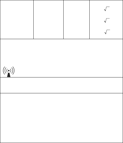
14.1. ELECTROMAGNETIC EMISSIONS
The SMARTVIEW monitor is intended for use in the electromagnetic
environment specified below. The customer or the user of the SMARTVIEW
monitor should assure that it is used in such an environment.
Emissions test Compliance Electromagnetic environment - guidance
RF emissions
CISPR 11 Group 1 The SMARTVIEW monitor uses RF energy
only for its internal function. Therefore, its RF
emissions are very low and are not likely to
cause any interference in nearby electronic
equipment.
RF emissions
CISPR 11 Class B The SMARTVIEW monitor is suitable for use
in all establishments, including domestic
establishments and those directly connected
to the public low voltage power supply
network that supplies buildings used for
domestic purposes.
Harmonic
emissions
IEC 61000-3-2
Class A
Voltage fluctuations
/ flicker emissions
IEC 61000-3-3
Complies

22 – ENGLISH
14.2. ELECTROMAGNETIC IMMUNITY
The SMARTVIEW monitor is intended for use in the electromagnetic
environment specified below. The user of the SMARTVIEW monitor should
assure that it is used in such an environment.
Immunity test IEC 60601 test
level Compliance
level Electromagnetic
environment -
guidance
Electrostatic discharge
(ESD)
IEC 61000-4-2
± 6 kV contact
± 8 kV air
± 6 kV contact
± 8 kV air
Floors should be
wood, concrete or
ceramic tile. If floors
are covered with
synthetic material,
the relative humidity
should be at least
30 %.
Electrical fast
transient/burst
IEC 61000-4-4
± 2 kV for power
supply lines
± 1 kV for
input/output lines
± 2 kV for
power supply
lines
± 1 kV for
input/output
lines
Mains power quality
should be that of a
typical home
environment.
Surge
IEC 61000-4-5
± 1 kV line(s) to
line(s)
± 2 kV line(s) to
earth
± 1 kV line(s) to
line(s)
± 2 kV line(s) to
earth
Mains power quality
should be that of a
typical home
environment.

ENGLISH – 23
Immunity test IEC 60601 test
level Compliance
level Electromagnetic
environment -
guidance
Voltage dips, short
interruptions and
voltage variations on
power supply input
lines
IEC 61000-4-11
<5 % UT
(>95 % dip in UT)
for 0,5 cycle
40 % UT
(60 % dip in UT)
for 5 cycles
70 % UT
(30 % dip in UT)
for 25 cycles
<5 % UT
(>95 % dip in UT)
for 5 s
<5 % UT
(>95 % dip in
UT)
for 0,5 cycle
40 % UT
(60 % dip in UT)
for 5 cycles
70 % UT
(30 % dip in UT)
for 25 cycles
<5 % UT
(>95 % dip in
UT)
for 5 s
Mains power quality
should be that of a
typical home
environment. If the
user of the
SMARTVIEW
monitor requires
continued operation
during power mains
interruptions, it is
recommended that
the SMARTVIEW
monitor be powered
from an
uninterruptible
power supply or a
battery.
Power frequency
(50/60 Hz) magnetic
field
IEC 61000-4-8
3 A/m 3 A/m Power frequency
magnetic fields
should be at levels
characteristic of a
typical bedroom in a
typical home
environment.
NOTE: UT is the a.c. mains voltage prior to application of the test level.
The SMARTVIEW monitor is intended for use in the electromagnetic
environment specified below. The customer or the user of the
SMARTVIEW monitor should assure that it is used in such an
environment.
Portable and mobile RF communications equipment should be used no
closer to the SMARTVIEW monitor, including cables, than the
recommended separation distance calculated from the equation
applicable to the frequency of the transmitter.
24 – ENGLISH
Recommended separation distance:
Conducted RF
IEC 61000-4-6
3 Vrms
150 kHz to
80 MHz
3 V Pd 2.1
Radiated RF
IEC 61000-4-3
3 V/m
80 MHz to
2.5 GHz
3 V/m
Pd 2.1 80 to
800 MHz
Pd 3.2
800 MHz to 2.5 GHz
where P is the maximum output power rating of the transmitter in watts (W) according to the
transmitter manufacturer and d is the recommended separation distance in metres (m).
Field strengths from fixed RF transmitters, as determined by an electromagnetic site
survey,a should be less than the compliance level in each frequency range.b
Interference may occur in the vicinity of equipment marked with the following symbol:
NOTE 1: At 80 MHz and 800 MHz, the higher frequency range applies.
NOTE 2: These guidelines may not apply in all situations. Electromagnetic propagation
is affected by absorption and reflection from structures, objects and people.
a Field strengths from fixed transmitters, such as base stations for radio
(cellular/cordless) telephones and land mobile radios, amateur radio, AM and FM radio
broadcast and TV broadcast cannot be predicted theoretically with accuracy. To assess
the electromagnetic environment due to fixed RF transmitters, an electromagnetic site
survey should be considered. If the measured field strength in the location in which the
SMARTVIEW monitor is used exceeds the applicable RF compliance level above, the
SMARTVIEW monitor should be observed to verify normal operation. If abnormal
performance is observed, additional measures may be necessary, such as re-orienting
or relocating the SMARTVIEW monitor.
b Over the frequency range 150 kHz to 80 MHz, field strengths should be less than
3 V/m.
ENGLISH – 25
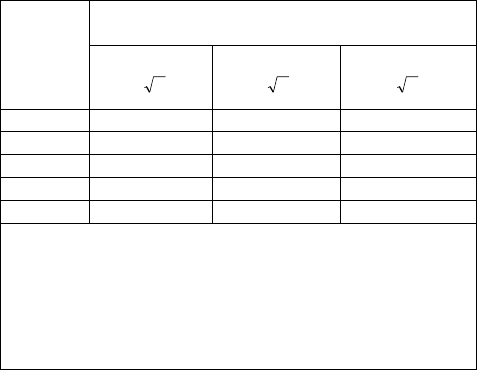
14.3. RECOMMENDED SEPARATION DISTANCES
BETWEEN PORTABLE AND MOBILE RF
COMMUNICATIONS EQUIPMENT AND THE
SMARTVIEW MONITOR
The SMARTVIEW monitor is intended for use in an electromagnetic
environment in which radiated RF disturbances are controlled. The user of
the SMARTVIEW monitor can help prevent electromagnetic interference by
maintaining a minimum distance between portable and mobile RF
communications equipment (transmitters) and the SMARTVIEW monitor as
recommended below, according to the maximum output power of the
communications equipment.
Rated
maximum
output
power of
transmitter
W
Separation distance according to frequency of transmitter
m
150 kHz to 80 MHz
Pd 2.1
80 MHz to 800 MHz
Pd 2.1
800 MHz to 2.5 GHz
Pd 3.2
0.01 0.12 0.12 0.23
0.1 0.38 0.38 0.73
1 1.2 1.2 2.3
10 3.8 3.8 7.3
100 12 12 23
For transmitters rated at a maximum output power not listed above, the recommended
separation distance d in meters (m) can be estimated using the equation applicable to the
frequency of the transmitter, where P is the maximum output power rating of the
transmitter in watts (W) according to the transmitter manufacturer.
NOTE 1: At 80 MHz and 800 MHz, the separation distance for the higher frequency range
applies.
NOTE 2: These guidelines may not apply in all situations. Electromagnetic propagation is
affected by absorption and reflection from structures, objects and people.

26 – ENGLISH
15. TECHNICAL ASSISTANCE
For any assistance or question you may have about your SMARTVIEW
monitor, please call our toll-free Sorin technical assistance.
Our technical assistance desk is open from Monday to Friday from
8:00 AM to 6:00 PM local time, except public holidays.
USA +1 855 877 3899
Last revision date of this manual: 2012-01
blank

Manufactured in for:
Sorin CRM S.r.l.
Via Crescentino s.n.
13040 Saluggia (VC) - Italy
Tel: +39 0161487095
Facsimile: +39 0161 487524
www.sorin.com
Distributed by:
Sorin CRM USA, Inc.
14401 West 65th Way
Arvada, CO 80004 USA
Tel: 877.663.7674
Facsimile: 763.383.4713 or 877.443.3134
*#*
201-