STONEX SRL B2029 GPS Receiver User Manual Contents
STONEX SRL GPS Receiver Contents
UserManual.wiki
>
STONEX SRL
>
B2029 User Manual
>
User Manual --4.18_Host
Contents
1.
User Manual --4.18_Host
2.
User Manual
User Manual --4.18_Host
Navigation menu
Upload a User Manual
Namespaces
Wiki Guide
HTML
PDF
Info
Views
User Manual
Discussion / Help
Navigation

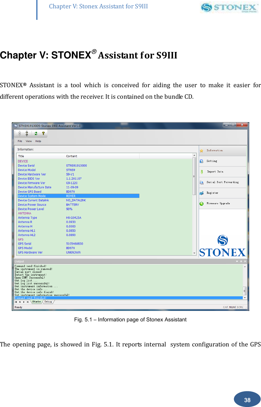
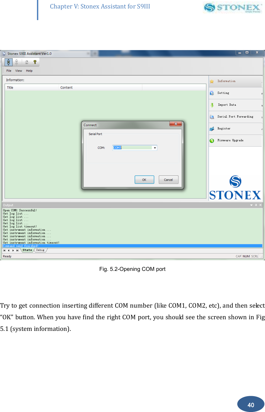
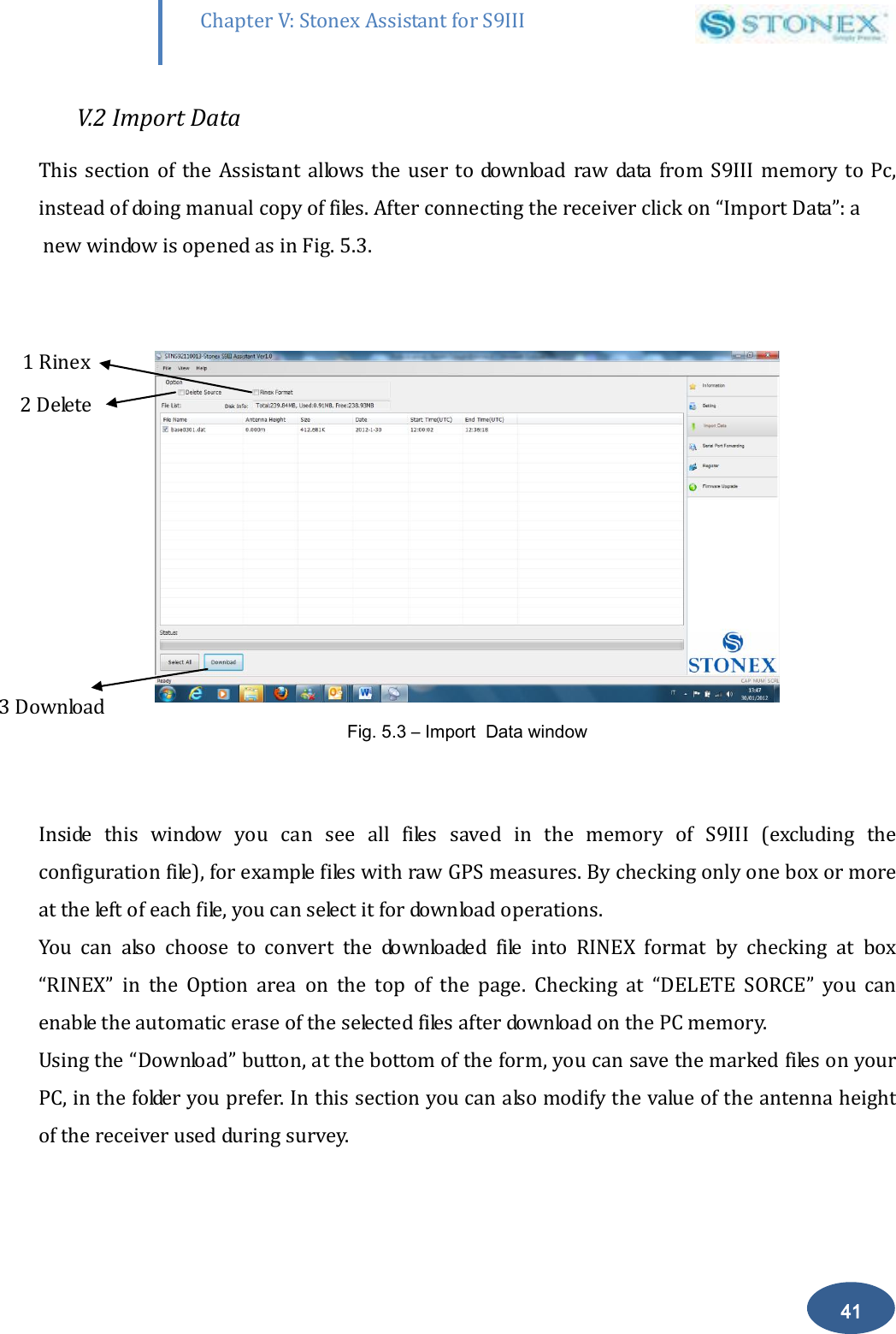
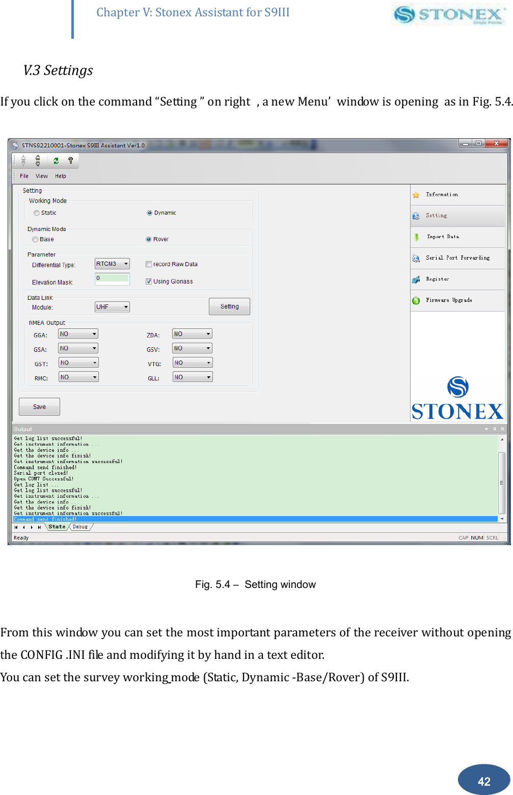
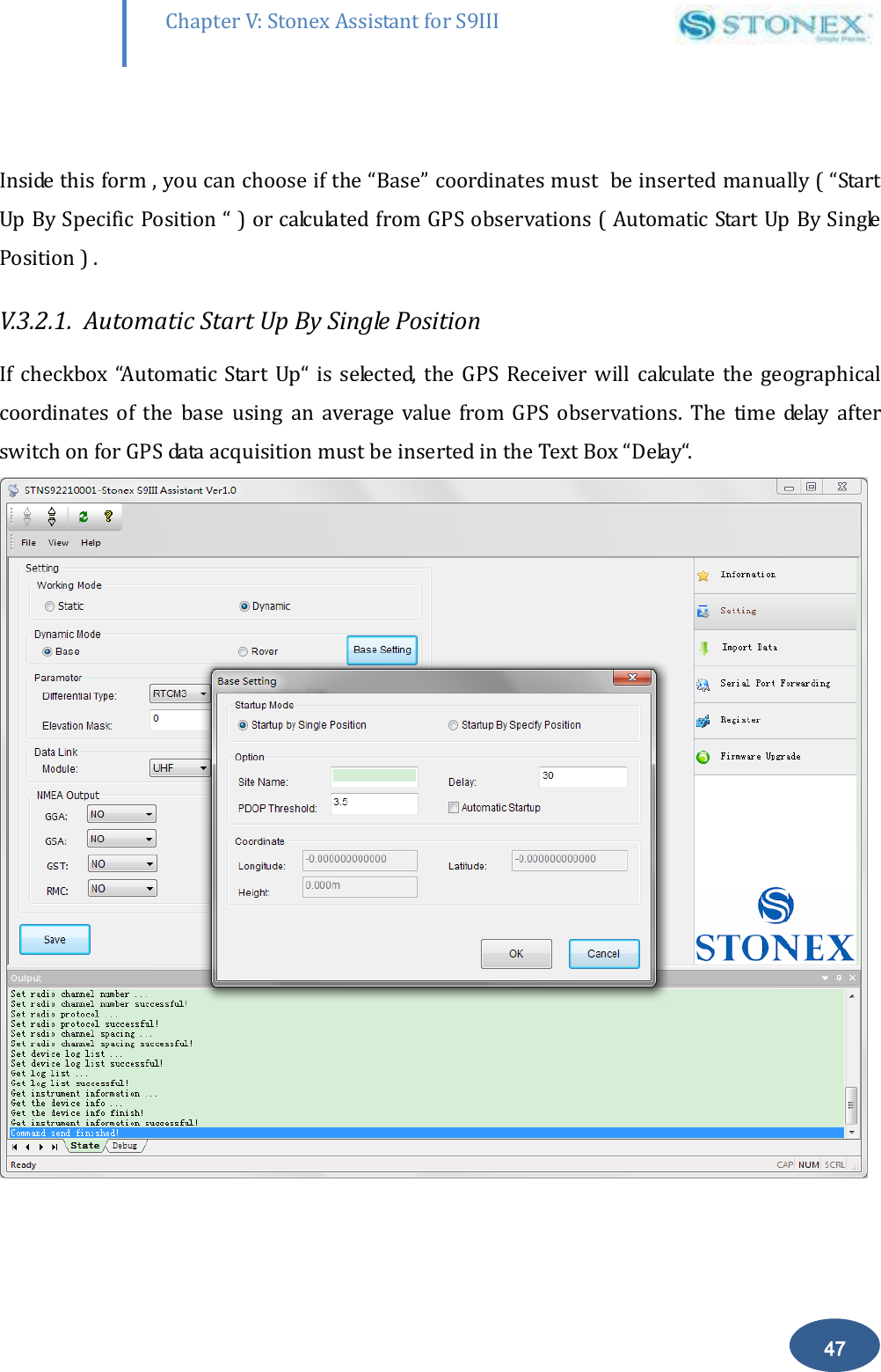
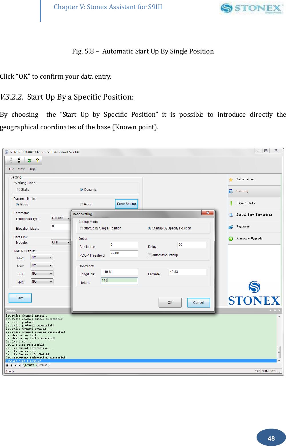
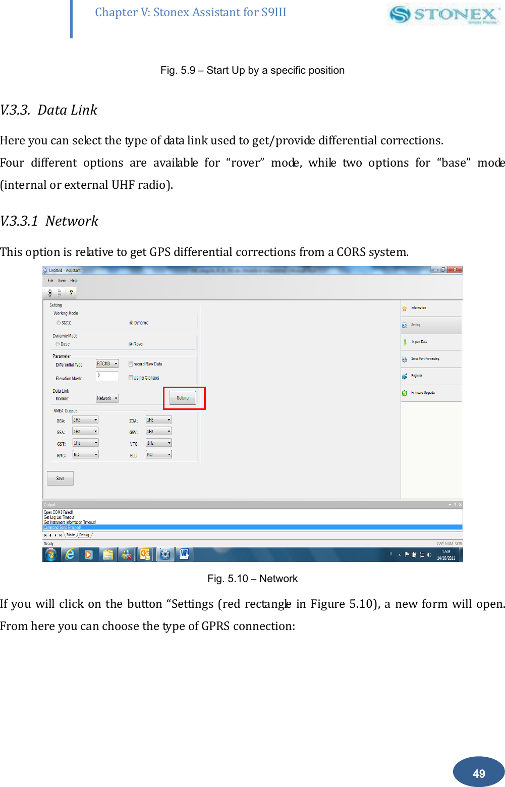
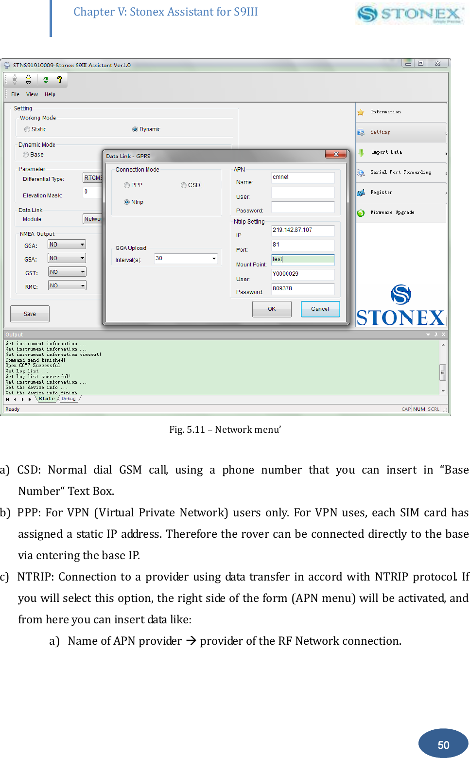
![Chapter IV : S9 III Operations 37 The license is composed of a 32 characters code. For inserting the new license you can use RTK software STONEX® SurvCE: you have to enter into the submenu “Equipment” “GPS utilities” “Send command”, then write the command “SET,DEVICE.REGI,[license code]”. However it is also possible to register the receiver using the STONEX® Assistant , a software tool which is explained in Chapter V.](https://usermanual.wiki/STONEX-SRL/B2029.User-Manual-4-18-Host/User-Guide-1961659-Page-37.png)