SafeWorks 1000 IBEX 1000 User Manual
SafeWorks, LLC IBEX 1000 Users Manual
Contents
- 1. Users Manual
- 2. Manual
Users Manual
Reference: 702991-1 Issue date: 20-Dec-2008 Revision: A Page 1 of 25
This document and all copies are the property of Power Climber Wind. All dimensions and data are indicative only.
The user must ensure that the equipment complies with local rules and regulations.
OPERATORS
MANUAL
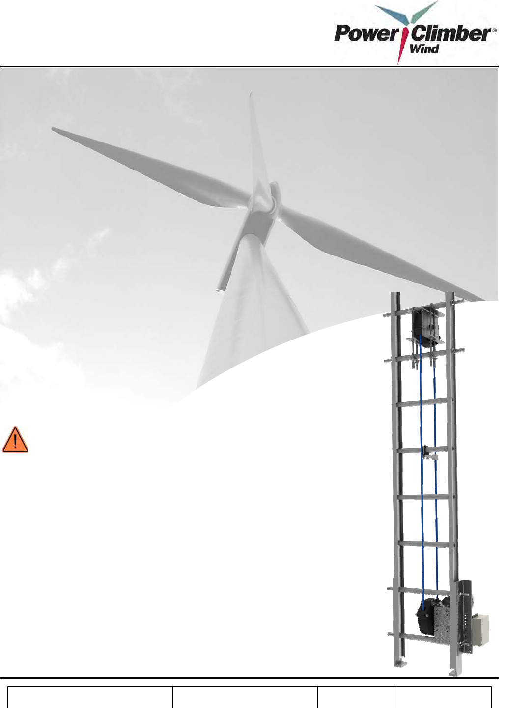
IBEX™1000 Series
Climb Assist System
(Models 1060, 1080, & 1100)
WARNING:
•
All personnel operating this equipment must read and completely
understand this manual.
• All personnel must be thoroughly trained in the use
of the
equipment and its operational and safety features.
•
Only authorized and physically fit personnel shall operate the
equipment.
•
All persons operating this equipment must wear a safety harness at
all times and tie-off as required.
• Any operation in viola
tion of these instructions is at the operator’s
own risk and may result in serious injury.
• This manual must be kept with the system at all times.
• Only use spare parts supplied by Power Climber Wind.

Reference: 702991-1 Issue date: 20-Dec-2008 Revision: A Page 2 of 25
This document and all copies are the property of Power Climber Wind. All dimensions and data are indicative only.
The user must ensure that the equipment complies with local rules and regulations.
Manufacturer
Power Climber Wind
A Division of SafeWorks, LLC
365 Upland Drive
Seattle, WA 98188
Customer Support
Tel: (800) PCWIND1 (729-4631)
or outside the U.S.: (206) 394-5319
Fax: (206) 577-6240
Email: CustomerService@PowerClimberWind.com
Web: www.PowerClimberWind.com

Reference: 702991-1 Issue date: 20-Dec-2008 Revision: A Page 3 of 25
This document and all copies are the property of Power Climber Wind. All dimensions and data are indicative only.
The user must ensure that the equipment complies with local rules and regulations.
Table of Contents
1. SYMBOLS USED IN THIS MANUAL ................................................................................................................4
2. EQUIPMENT DESCRIPTION ..............................................................................................................................5
2.1 General Description .........................................................................................................................................5
2.2 Specifications ...................................................................................................................................................5
2.3 Approvals .........................................................................................................................................................5
2.4 General View ...................................................................................................................................................7
3. IBEX™ 1000 ASSEMBLY INSTRUCTIONS......................................................................................................8
3.1 Components .....................................................................................................................................................8
3.2 Assembly Process...........................................................................................................................................10
3.3 Commissioning ..............................................................................................................................................17
4. IBEX™ 1000 OPERATION INSTRUCTIONS ..................................................................................................19
4.1 IBEX™ 1000 Features...................................................................................................................................19
4.2 Use of the EasyClimb Controller ...................................................................................................................19
4.3 Safety .............................................................................................................................................................21
5. IBEX™ 1000 MAINTENANCE INSTRUCTIONS............................................................................................22
5.1 Periodic Inspection.........................................................................................................................................22
5.2 Troubleshooting .............................................................................................................................................23
5.3 Replacement of Damaged Components .........................................................................................................23
5.4 Electrical Schematics and Wiring Diagrams..................................................................................................24
5.5 Spare Parts List ..............................................................................................................................................25
5.6 Customer Service ...........................................................................................................................................25
Reference: 702991-1 Issue date: 20-Dec-2008 Revision: A Page 4 of 25
This document and all copies are the property of Power Climber Wind. All dimensions and data are indicative only.
The user must ensure that the equipment complies with local rules and regulations.
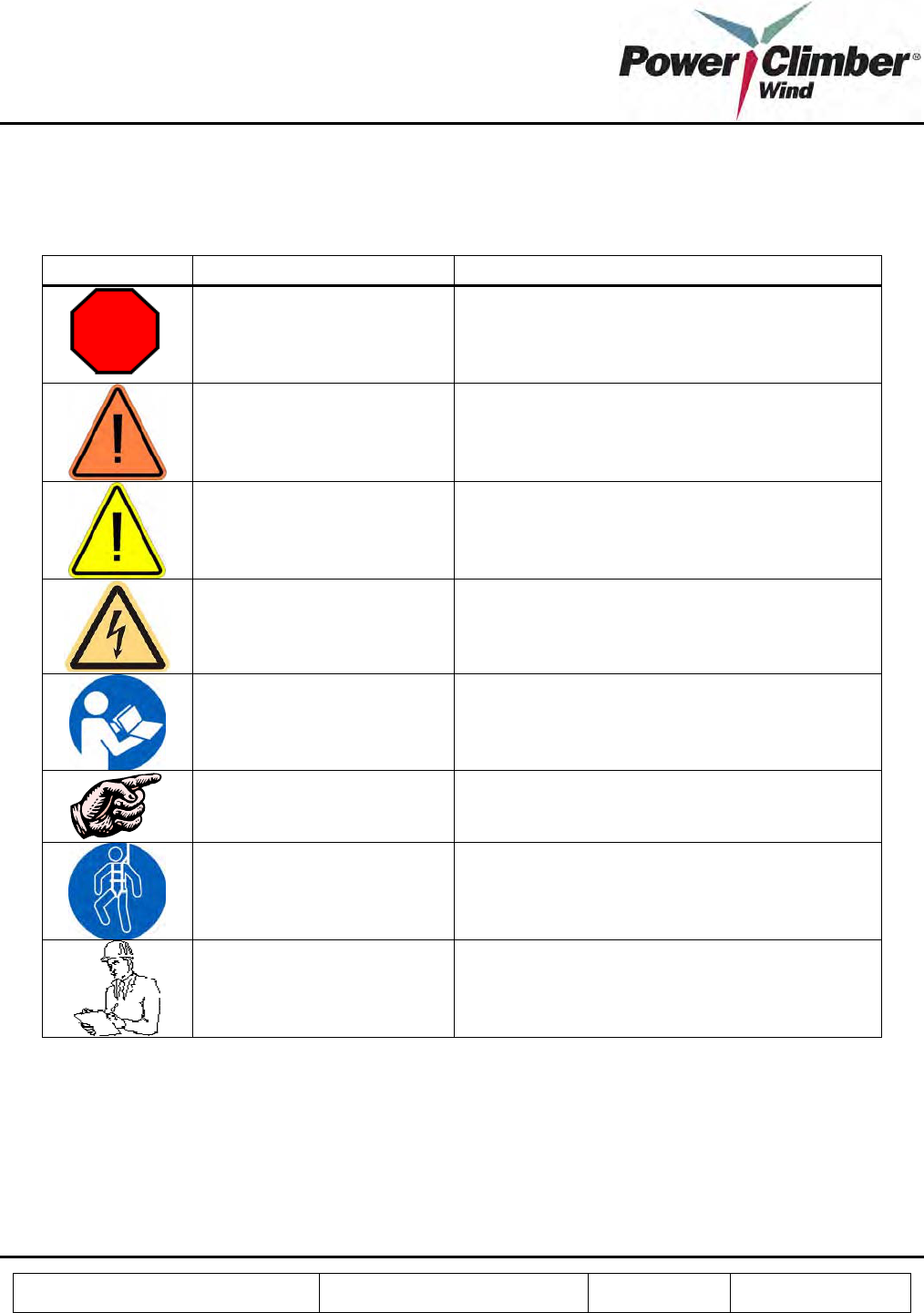
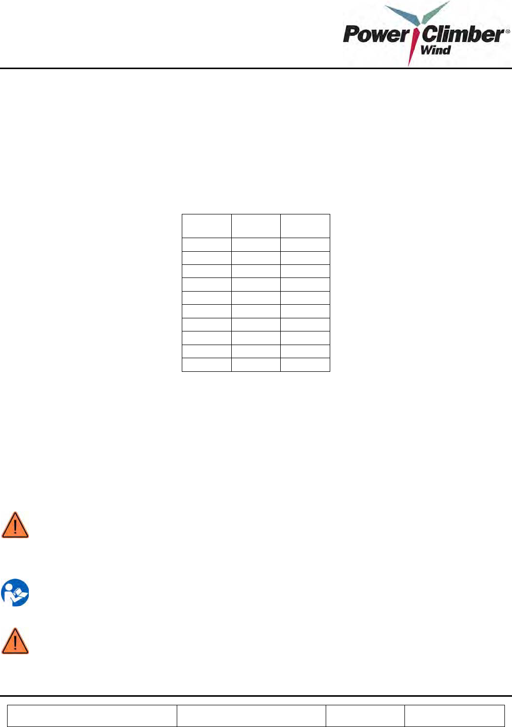
1. SYMBOLS USED IN THIS MANUAL
SYMBOL TERM MEANING
STOP Stop action and follow the instructions before
continuing.
WARNING Warns against possible immediate serious injury
or death.
CAUTION Warns against possible injury.
ELECTRICAL HAZARD Warns against possible electrical shock hazard.
NOTE Must read this before performing any action that
follows.
TIP Remember and take this into account.
SAFETY GEAR Mandatory use of safety gear.
DOCUMENT Make sure to document any items of interest and
processes performed.
Reference: 702991-1 Issue date: 20-Dec-2008 Revision: A Page 5 of 25
This document and all copies are the property of Power Climber Wind. All dimensions and data are indicative only.
The user must ensure that the equipment complies with local rules and regulations.
2. EQUIPMENT DESCRIPTION
2.1 General Description
The IBEX™ 1000 climb assist system is a motorized, continuous loop system that provides load support to the
climber on both the ascent and descent. The system allows user-adjustable support settings at 50, 75, 100, and
125 pounds, and provides constant load support regardless of climbing speed via a closed feedback loop between
the motor drive and load-sensing EasyClimb Controller that attaches the climber to the belt.
The mounting system is adaptable and can be fitted to any ladder or tower with minimal adjustment necessary
(excluding the belt, which must be sized appropriately).
The IBEX™ is permanently installed on a specific WTG ladder and consists of:
1. Top sheave assembly and mounting
2. Gear motor
3. Bottom sheave assembly and mounting
4. Electrical control box
5. EasyClimb Controller
6. Round reinforced polymer belt and belt guides
7. Upper and lower ladder rung reinforcements
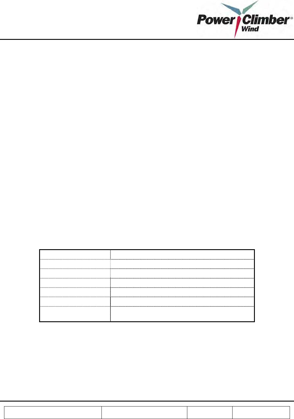
2.2 Specifications
Power Supply 110Vac 60 Hz; 230 Vac 50 Hz 1ø, 0.5HP Motor
Amperage Draw 5.2 maximum
Belt Diameter 10.5mm
Environmental Rating IP55
Corrosion Protection Class 3
Noise level 75 dBA
Temperature Range -35C to +40 C Operating
-40C to +60C Storage
2.3 Approvals
All electrical components of the IBEX™ 1000 are cUL-listed. Moving parts are guarded in compliance with
OSHA 1917.151.
This device has been tested and found to comply with the limits for a Class A digital device, pursuant to 47 CFR
Part 15 of the FCC rules. This equipment generates, uses and can radiate radio frequency energy and, if not
Reference: 702991-1 Issue date: 20-Dec-2008 Revision: A Page 6 of 25
This document and all copies are the property of Power Climber Wind. All dimensions and data are indicative only.
The user must ensure that the equipment complies with local rules and regulations.
installed and used in accordance with the instructions, may cause harmful interference to radio communications.
Operation is subject to the following two conditions:
1. This device may not cause harmful interference, and
2. This device must accept any interference received, including interference that may cause undesired
operation of the device.
FCC Warning: Changes or modifications not expressly approved by Power Climber Wind for compliance could
void the user’s authority to operate the equipment.
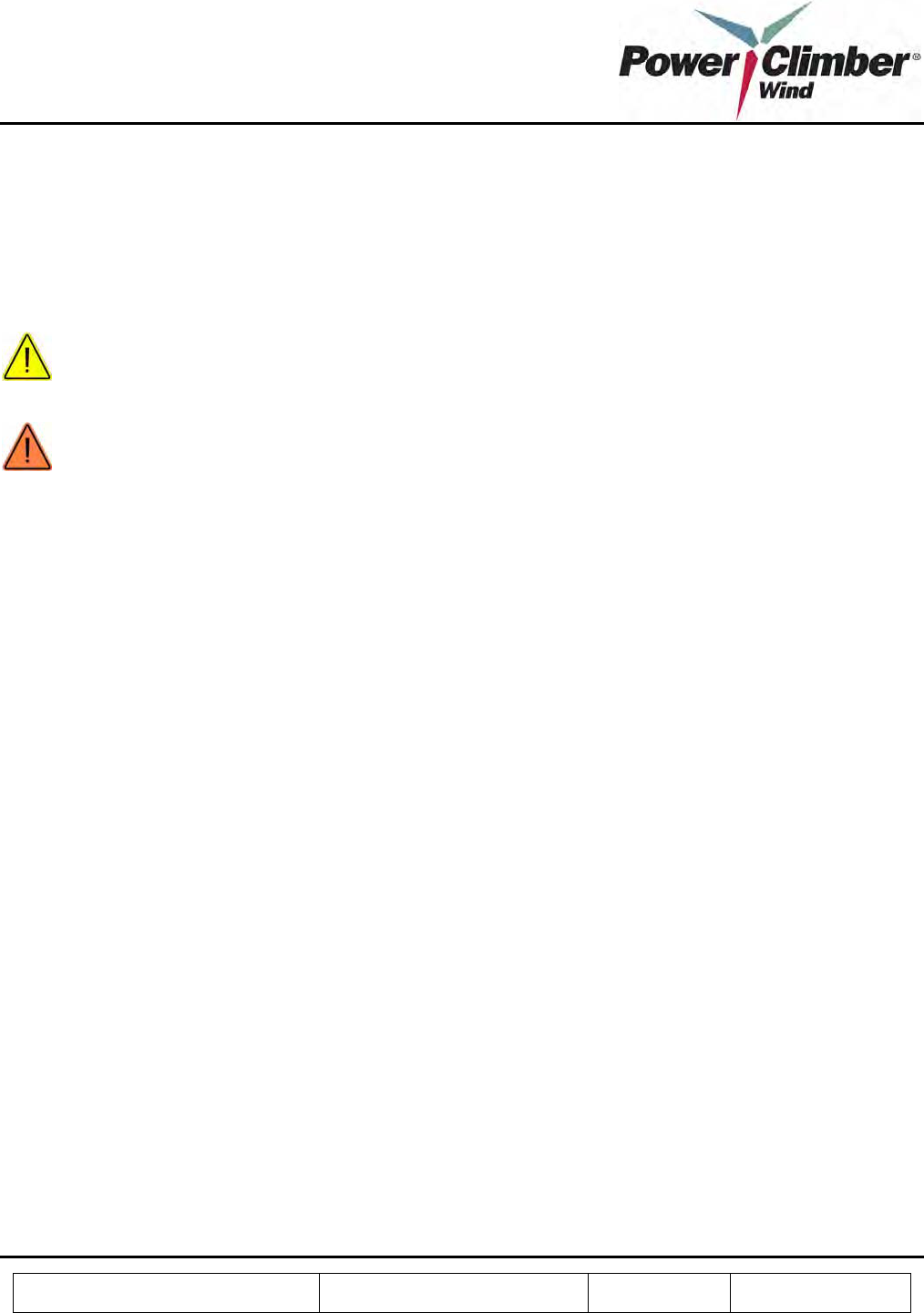
CAUTION: People with implanted pacemakers should not use this equipment. Radio waves could have
unexpected effects on the operation of medical devices.
WARNING: The IBEX™ 1000 climb assist system is NOT a safety device and must only be used in
conjunction with an independent personal fall arrest system.
Reference: 702991-1 Issue date: 20-Dec-2008 Revision: A Page 7 of 25
This document and all copies are the property of Power Climber Wind. All dimensions and data are indicative only.
The user must ensure that the equipment complies with local rules and regulations.
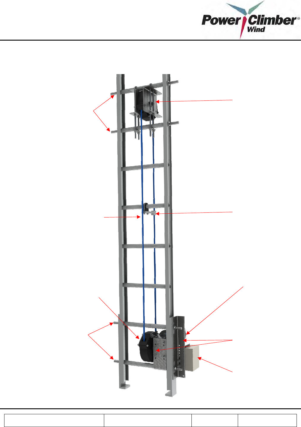
2.4 General View
Top
s
heave assembly
Belt guide
Electrical control box
Lower rung reinforcements
Upper rung reinforcements
Gear motor
Motor mounting
brackets
Drive sheave assembly
Round reinforced polymer belt
Reference: 702991-1 Issue date: 20-Dec-2008 Revision: A Page 8 of 25
This document and all copies are the property of Power Climber Wind. All dimensions and data are indicative only.
The user must ensure that the equipment complies with local rules and regulations.
3. IBEX™ 1000 ASSEMBLY INSTRUCTIONS
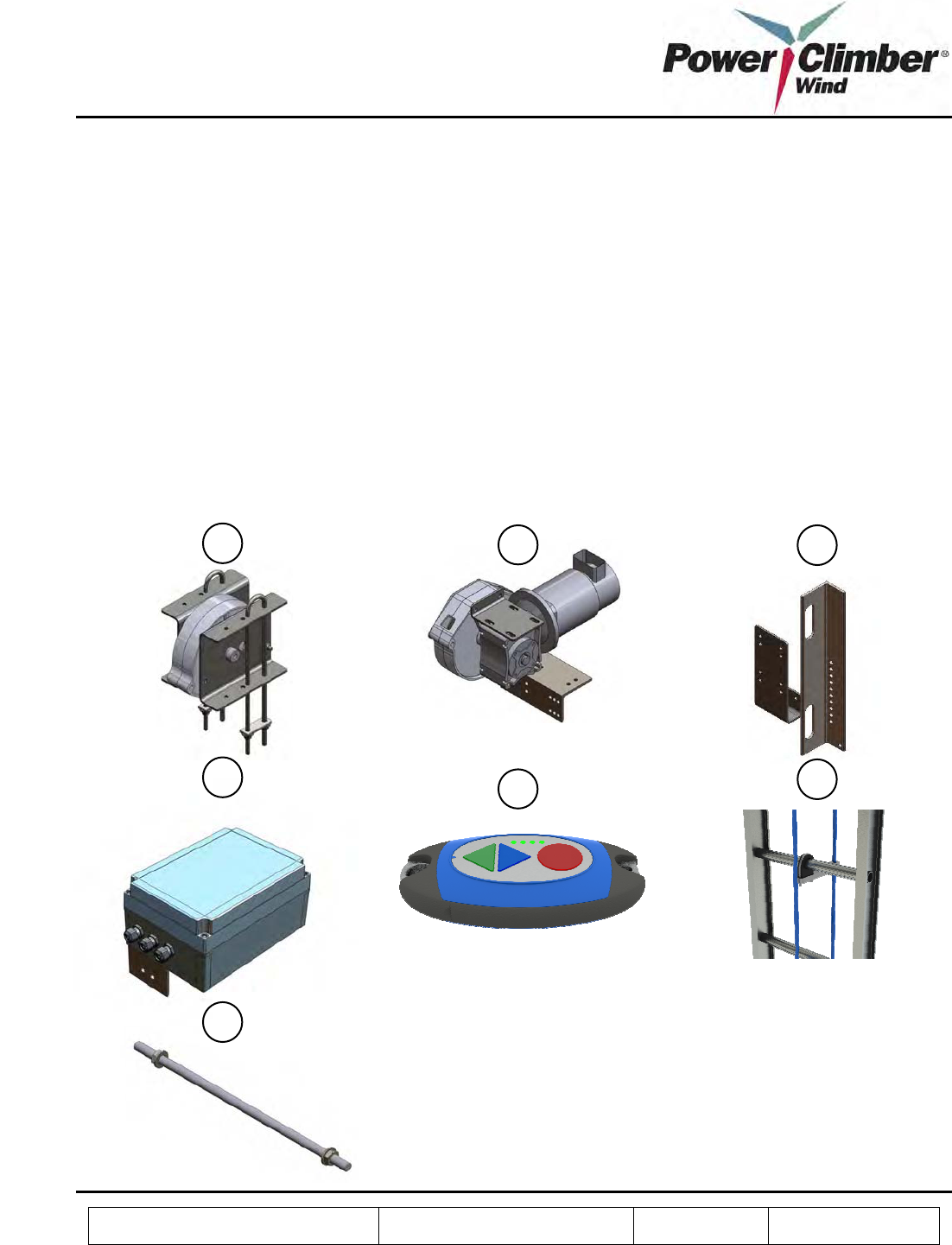
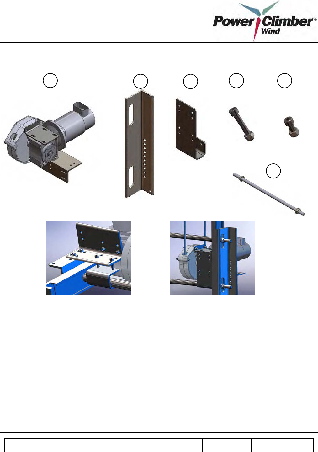
3.1 Components
The IBEX™ 1000 climb assist system consists of the following parts:
1. Top sheave assembly and mounting hardware
2. Gear motor assembly
3. Gear motor mounting brackets
4. Electrical control box
5. EasyClimb Controller
6. Round reinforced polymer belt and belt guides
7. Upper and lower rung reinforcements
1 2 3
4 5 6
7
Reference: 702991-1 Issue date: 20-Dec-2008 Revision: A Page 9 of 25
This document and all copies are the property of Power Climber Wind. All dimensions and data are indicative only.
The user must ensure that the equipment complies with local rules and regulations.
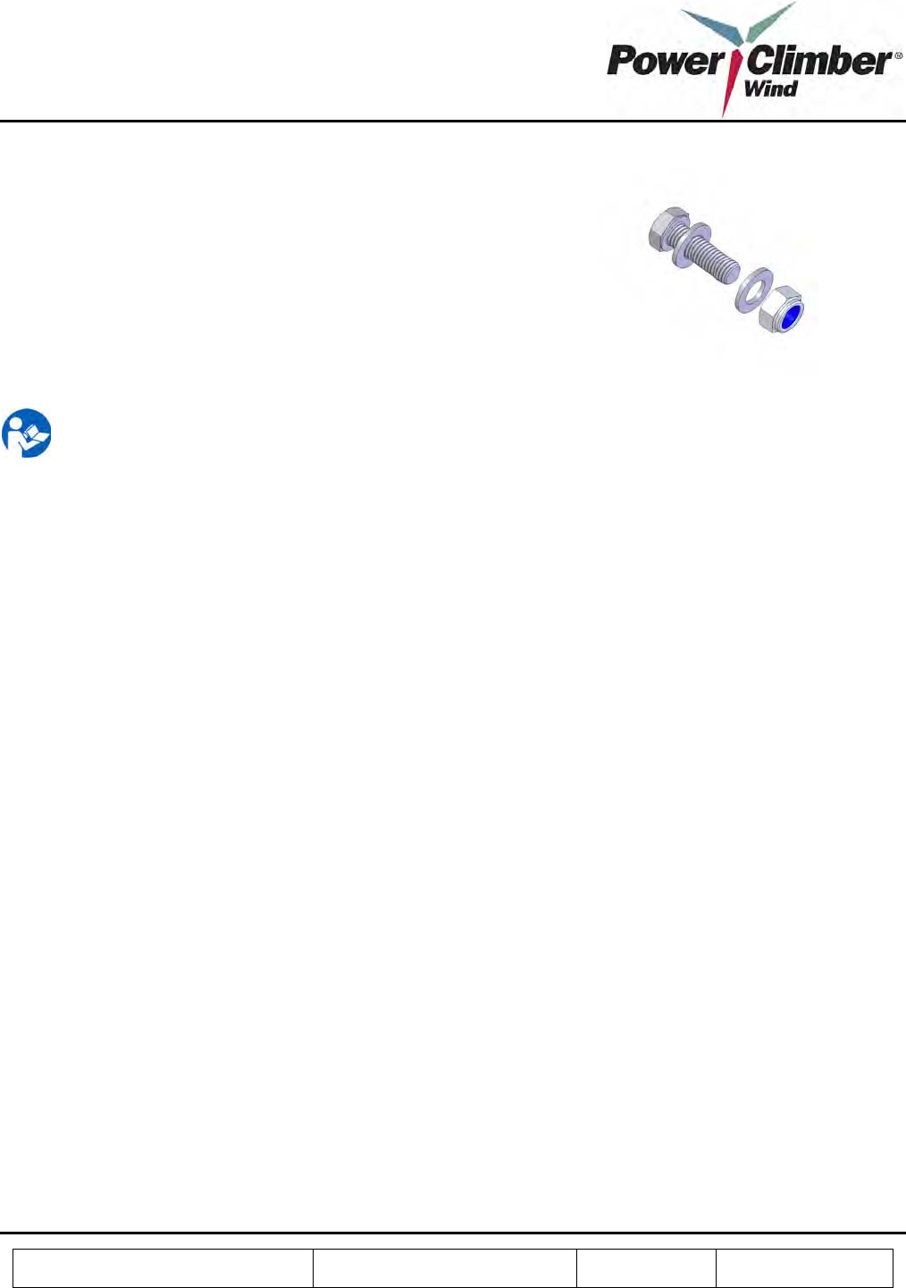
Fasteners:
• The components of the IBEX™ 1000 are assembled using
standard fasteners.
• Always apply anti-sieze (Loctite 8065, provided with
packing) on the bolts before tightening.
• Two washers are to be used on every bolt - one at the nut
side and one at the head of the bolt.
• All bolts should be firmly tightened. If nylon lock nut is
used, bolt thread shall protrude passed the nylon lock nut by
at least one thread. If a lock washer is used, bolt should be
tightened to compress lock washer flat.
NOTE: Either a lock washer of Nylok nut shall be used for all fasteners for field assembly
Reference: 702991-1 Issue date: 20-Dec-2008 Revision: A Page 10 of 25
This document and all copies are the property of Power Climber Wind. All dimensions and data are indicative only.
The user must ensure that the equipment complies with local rules and regulations.
3.2 Assembly Process
Unpack the IBEX™ 1000 packing box and verify its contents against the enclosed packing list. Follow the below
instructions to install the system on a ladder.
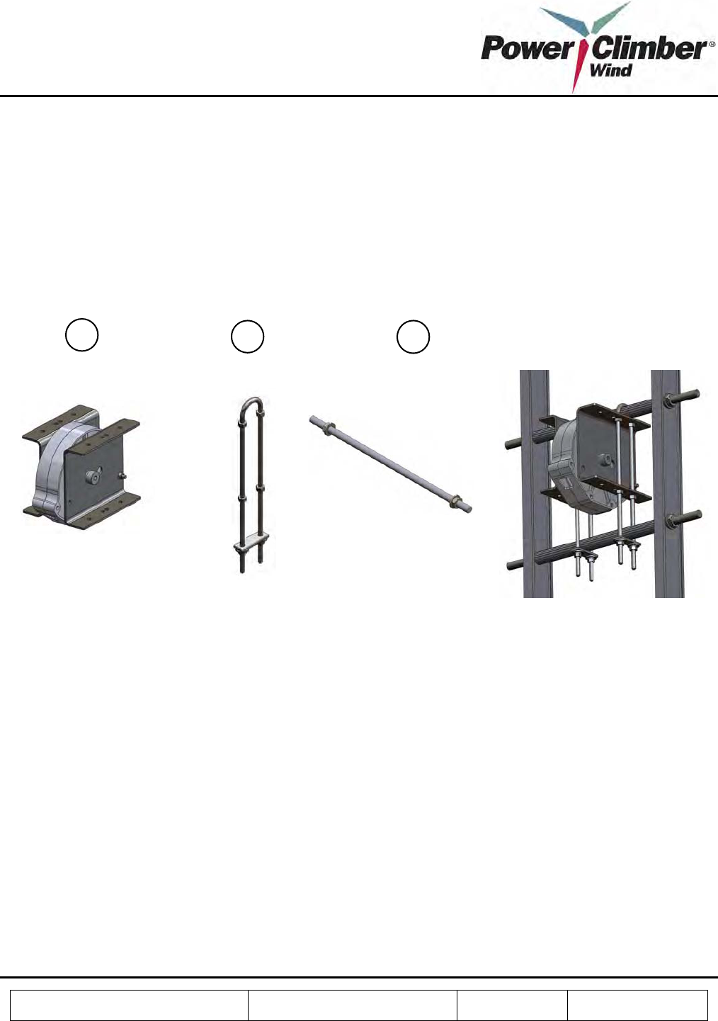
Top Sheave Assembly
1. Remove nuts, washers and plate from U bolt (B) and rung reinforcement (C).
2. Install rung reinforcement thru desired rung and the next rung below it. Install washer and nuts to ends 4
times. Tighten nuts at each end so there is an even amount of exposed threads on either side.
3. Hold Top Sheave (A) below the top rung with rung reinforcement .
4. Put U bolt over reinforced rung and thru mounting plate holes at top only.
5. Install one nut on both sides and start tightening, as you tighten allow the U bolt to continue threw the
lower mounting plate holes and tighten.
6. Install one nut on both sides to secure the bottom of the mounting plate.
7. Install plate, washers and nuts and tighten.
8. Repeat steps 4-7 for other side.
B C
A
Reference: 702991-1 Issue date: 20-Dec-2008 Revision: A Page 11 of 25
This document and all copies are the property of Power Climber Wind. All dimensions and data are indicative only.
The user must ensure that the equipment complies with local rules and regulations.
Motor and Drive Sheave Assembly
1. Remove nuts, washers from rung reinforcement (F).
2. Install rung reinforcement thru desired rung and the next rung above it.
3. Take brace (C) and mount it larger face forward and touching the lower reinforced rung.
4. Hold Motor / Drive Sheave align with desired mounting holes on brace (C) aligning the holes on the gear
box.
5. Install nuts and bolts (E) 4 times and tighten.
6. Install nuts and bolts (D) 2 times and tighten.
7. Take brace (B) slide over ends of rung reinforcement and align to holes on Motor / Drive Sheave.
8. Install nuts and bolts (E) 2 times and tighten.
9. Install washer and nuts to ends of rung reinforcement 4 times. Tighten nuts at each end so there is an even
amount of exposed threads on either side.
10. Check for alignment with Top Sheave and adjust as needed by loosing nuts and bolts and retightening
them.
B C D E
F
A
Reference: 702991-1 Issue date: 20-Dec-2008 Revision: A Page 12 of 25
This document and all copies are the property of Power Climber Wind. All dimensions and data are indicative only.
The user must ensure that the equipment complies with local rules and regulations.
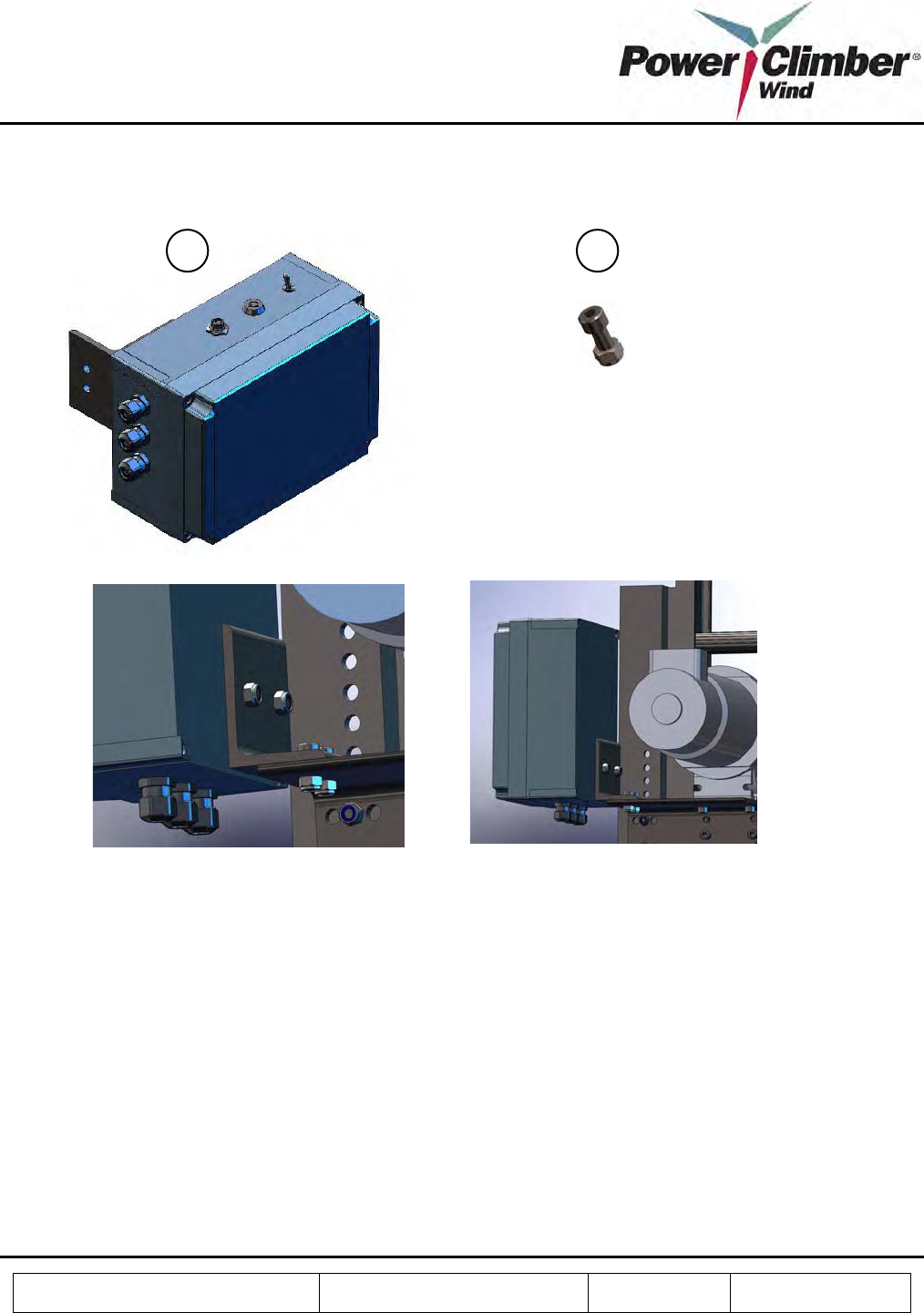
Electrical Control Box and Connections
.
1. Bolt the electrical box to the motor mounting brackets as shown using bolts (B) 2 times.
2. Connect the power cable to the tower single phase supply but do not apply power.
3. Open the cabinet lid.
4. Using 20A SOW (or equivalent) cable, feed the cable through the gland and wire the 115V connection
point to the tower supply point.
5. Connect the prewired short cable to the motor terminals. Ensure the frame ground terminal at the motor
is connected.
6. Mount the antenna on a convenient place close to the control cabinet.
7. Feed the SMA connector on the coax cable through the gland and connect to the ANT socket on the Host
pcb.
8. Close the lid.
A B
Reference: 702991-1 Issue date: 20-Dec-2008 Revision: A Page 13 of 25
This document and all copies are the property of Power Climber Wind. All dimensions and data are indicative only.
The user must ensure that the equipment complies with local rules and regulations.
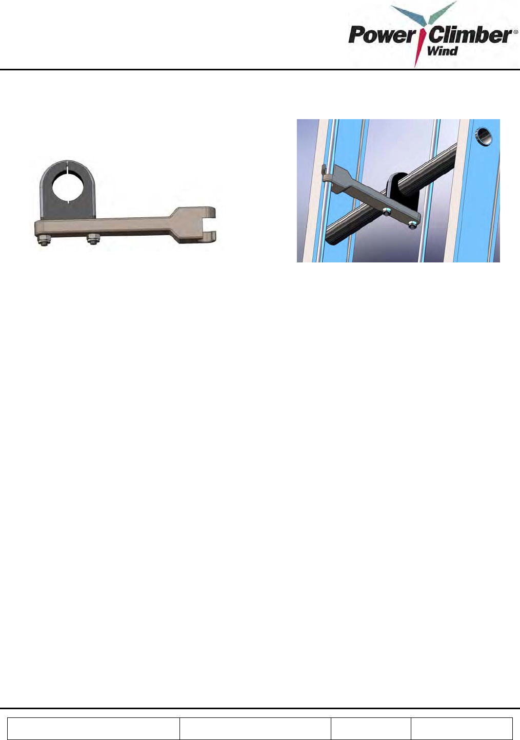
Belt Guide Installation
1. Install belt guides as shown at each landing opposite the climbing side at each intermediate platform and
elsewhere as needed to prevent abrasion and stabilize belt travel.
Belt Installation
1. Place the leader rope and belt coil on the decoiler at the base of the ladder landing under the mezzanine.
2. Worker 1 climbs:
a. Feed the leader rope (previously hoisted to the top) through the sheave and shroud.
b. Attach a 5 lb weight to the leader rope end.
c. Lower the leader rope down the non-climb side of the ladder.
d. Tie off the end of the leader rope at the top.
3. Worker 2 at base:
a. Disconnect the weight and attach the Kellums grip loop to the end of the leader rope.
b. Attach the Kellums grip mesh to the free end of the belt and feed it as Worker 1 raises the belt to
the top up the non-climb side of the ladder.
4. Worker 1 at top:
a. Pull the leader rope up to raise the belt.
b. When belt reaches top with a 3 ft overlap, tie off the belt to prevent it from dropping (use a rope
grab tied off to the ladder rail).
c. Remove the Kellums grip and feed the belt through the sheave and shroud to the climb side.
d. Replace the Kellums grip on the belt end and attach it to the side D-ring of the harness. (use a
caribiner)
e. Climb down wile pulling the belt down.
5. Worker 2 at base:
a. Continue to assist belt to feed off the decoiler.
b. When the belt end reaches the base, tie off to the ladder.
6. Cut the belt off the coil and feed the end through the motor shroud to the climb side ensuring sufficient
belt available for tensioning and welding, and tie off.
7. Hoist coil of round belt to yaw deck. Feed through top sheave and lower each side down tower to bottom
or ladder. Feed back side belt through drive sheave so that both loose ends are on the climber side of the
ladder.
Reference: 702991-1 Issue date: 20-Dec-2008 Revision: A Page 14 of 25
This document and all copies are the property of Power Climber Wind. All dimensions and data are indicative only.
The user must ensure that the equipment complies with local rules and regulations.
Splicing Procedure
1. Include operation of come along and tensioning requirement
2. Open the overlap welding kit.
3. Securely fasten welder to the ladder at shoulder level
4. Use the come-along to tension the loose ends of the belt. Using the dynamometer, apply tension
according to the following table:
degC
Load
(kg)
Load
(lbs)
-10 119.7 263
-5 104.4 230
0 89.1 196
5 81.9 180
10 74.7 164
15 70.65 155
20 66.6 147
25 62.55 138
30 58.5 129
35 56.25 124
5. Examine the light green coated surface of the heating element for scratches. A scratched and damaged
coated surface can affect weld results; heating element may need replaced.
6. On the front of the control box is an on/off switch, indicator light and fuse holder. On the left side of the
control box is a power supply line and thermocouple. Plug the power supply line and thermocouple into
the left side of the control box. On the right side of the control box is the main power cord that is plugged
into an 110/120v electrical power source.
7. On top of the control box is the temperature control dial. Set the control dial at 500°F. Turn the power
switch to the on position. The large red indicator light will stay on. On the temperature control dial, an
indicator light will come on and remain on while element is heating.
WARNING: Do not start welding until this light goes out the first time.
This indicator light will then fluctuate on and off as the heating element maintains the correct welding
temperature.
NOTE: If light green coated surface contains polyurethane residue, use a clean, dry cloth to remove it.
WARNING: Do not use any object to scrape polyurethane from surface.
Reference: 702991-1 Issue date: 20-Dec-2008 Revision: A Page 15 of 25
This document and all copies are the property of Power Climber Wind. All dimensions and data are indicative only.
The user must ensure that the equipment complies with local rules and regulations.
8. Turn large wing nut several turns counter-clockwise until it stops. Pull back on red knob on front
(sliding) die. Push down on black knob on top of welder and pull brass pin out to release coated heating
element. Swing heating element away from die area.
9. Insert a black star-shaped thumbnut into each die and finger-tighten as in Figure 1.
Figure 1
10. Using the cutting shears provided, cut each end of round belt at a 15°angle as in Figure 2.
Figure 2
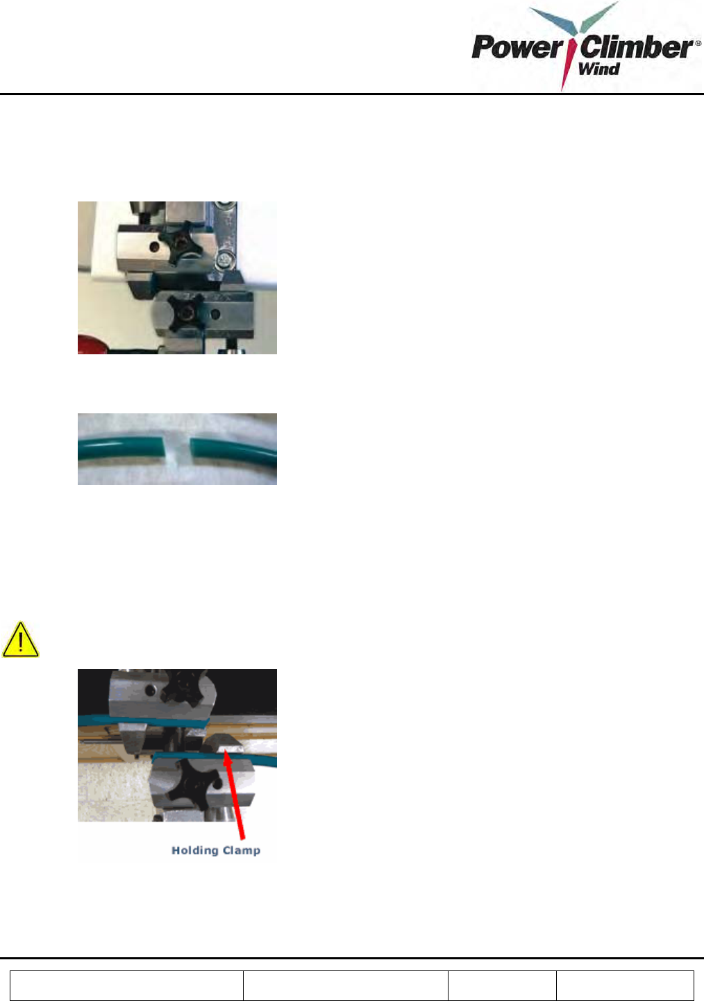
11. Slide end of the round belt into the rear die until it overhangs approximately 1/16" and angle on belt is
parallel with angle on die. Clamp the belt into position by lightly tightening the knurled thumbnut finger
tight. On the front (sliding) die, the flat side of the holding clamp must face up. If not, turn knurled
thumbnut counter-clockwise and remove. Push holding clamp from base and rotate clamp 180° until flat
side is up. Reassemble knurled thumbnut. Slide end of belt into front die and position exactly same as rear
die. Lightly finger-tighten knurled thumbnut. See Figure 3.
CAUTION: Make sure belt does not contain any twist.
Figure 3
12. Swing the green coated heating element into position between dies. Pull out on brass pin, push down and
hold black knob (on top of welder) and release brass pin. This locks heating element into position.
Reference: 702991-1 Issue date: 20-Dec-2008 Revision: A Page 16 of 25
This document and all copies are the property of Power Climber Wind. All dimensions and data are indicative only.
The user must ensure that the equipment complies with local rules and regulations.
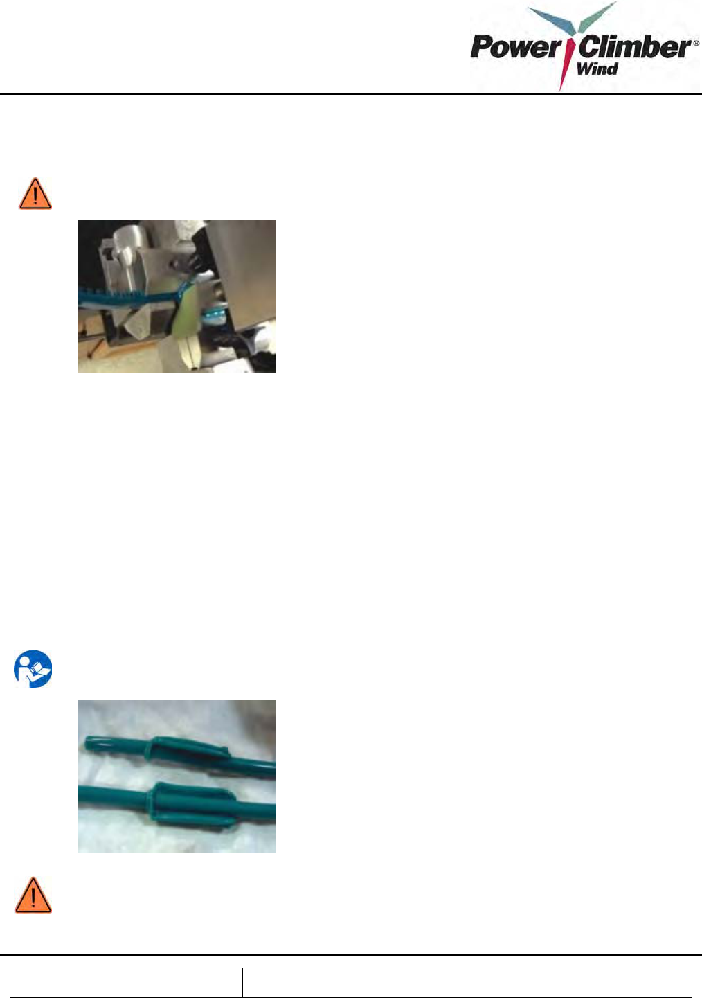
13. Turn large wing nut clockwise, moving it forward until both overlapping surfaces contact the coated
heating element. Continue turning large wing nut as belt ends melt and material is squeezed out of weld
area. Continue turning large wing nut until it stops. See Figure 4.
WARNING: do not over tighten.
Figure 4
14. After a maximum of 20 seconds, turn large wing nut counter-clockwise 3-4 full turns. Pull back on red
knob until the front (sliding) die stops. Push down on black knob on top of welder; on back of welder,
slightly push on the two guide rods to move coated heating element. Pull brass pin out and release coated
heating element. Swing heating element away from die area. Immediately push red knob forward and
quickly spin large wing nut clockwise until stop is reached.
Important: This sequence must be done very quickly.
15. While weld is cooling, use a clean, dry cloth to wipe excess polyurethane material from coated heating
element. It is important that heating element be cleaned between every weld.
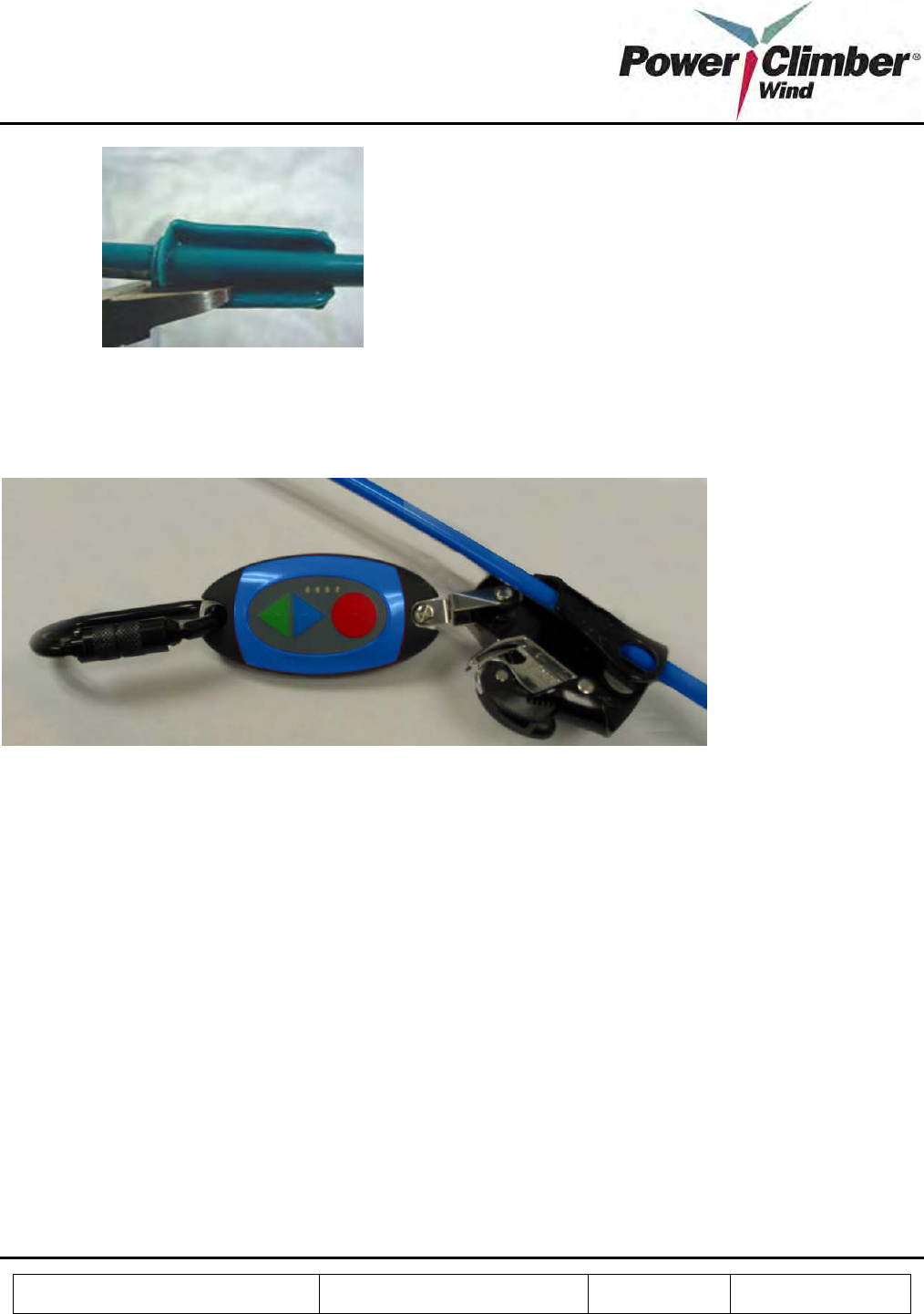
16. After a minimum of one minute, turn large wing nut counter-clockwise several turns. Loosen both
knurled thumbnuts several turns and pull back on red knob on front (sliding) die. Remove belt from
welder, and using special flash cutters trim weld flash from belt, Figure 5.
NOTE: The flash cutters have been designed specifically for trimming polyurethane and are not to be
used for cutting metal, wire, etc.
Figure 5
WARNING: Allow the belt to cure for a minimum of ½ hour prior to installing, tensioning or putting
strain on the belt weld.
Reference: 702991-1 Issue date: 20-Dec-2008 Revision: A Page 17 of 25
This document and all copies are the property of Power Climber Wind. All dimensions and data are indicative only.
The user must ensure that the equipment complies with local rules and regulations.
Figure 9
EasyClimb Controller
The EasyClimb Controller assembly includes an integrated rope grab and carabiner to connect it to the user’s
harness at the front D-Ring. The EasyClimb Controller must be charged for 24 hours using the enclosed 12Vdc
wall transformer. When not in use the EasyClimb Controller may be safely placed on charge for an unlimited
period.
3.3 Commissioning
After installation of drive, top sheave, controls and belt, carry out the following steps to commission the installed
IBEX™ 1000 climb assist system.
EasyClimb Controller
1. Review section 4.2 below on the operation of the EasyClimb Controller.
2. Press STOP: verify all 4 LEDs flash once.
3. Press and hold STOP, press UP: verify one LED flashes and sequentially cycles in the up direction.
Release STOP.
4. Press and hold STOP, press DOWN: verify one LED flashes and sequentially cycles in the down
direction. Release Stop.

Reference: 702991-1 Issue date: 20-Dec-2008 Revision: A Page 18 of 25
This document and all copies are the property of Power Climber Wind. All dimensions and data are indicative only.
The user must ensure that the equipment complies with local rules and regulations.
5. Wait at least 30 sec after last button operation then repeat 2.
System
(Do not connect EasyClimb Controller to belt)
6. Verify belt tension is set according to the table in section 3.2.
7. Connect power to the unit.
8. Set key to Inspect and turn on the power: Verify that the belt runs down (at nominally 60 fpm)
9. Set key to run. Verify belt stops.
10. Press Up (EasyClimb Controller): Verify belt runs up slowly for 2 to 3 seconds.
11. Set EasyClimb Controller to 50 lbs in UP and DOWN direction.
12. Attach rope grab to safety wire.
13. Apply a load to the harness attachment point of the EasyClimb Controller.
14. Press UP (twice if needed): Verify that the belt moves up at a speed that varies inversely with the load
applied to the EasyClimb Controller.
15. While load is applied and the belt is running, press STOP: Verify that the belt stops and does not respond
to load.
16. Press the DOWN button (twice if needed).
17. Apply a load to the EasyClimb Controller (there may be a short delay in start): Verify that the belt moves
down at a speed that varies with the load applied to the EasyClimb Controller.
18. Take all load off the EasyClimb Controller. Verify that the belt stops, and restarts if load is reapplied
within 10 seconds, otherwise remains stopped.
19. Press DOWN (twice if needed).
20. Before the 10 second delay completes, apply a load to the EasyClimb Controller (there may be a short
delay in start): Verify that the belt moves up at a speed that varies with the load applied to the EasyClimb
Controller.
21. While load is applied, press STOP: Verify the the belt stops and does not respond to load.
22. Angle the EasyClimb Controller down and press UP multiple times: Verify that the belt remains
stationary.
Ride Quality
23. Cycle the power switch to ensure the system is reset.
24. Connect the rope grab to the belt and the caribiner to the harness.
25. Test ride to ensure proper function of system.
Reference: 702991-1 Issue date: 20-Dec-2008 Revision: A Page 19 of 25
This document and all copies are the property of Power Climber Wind. All dimensions and data are indicative only.
The user must ensure that the equipment complies with local rules and regulations.
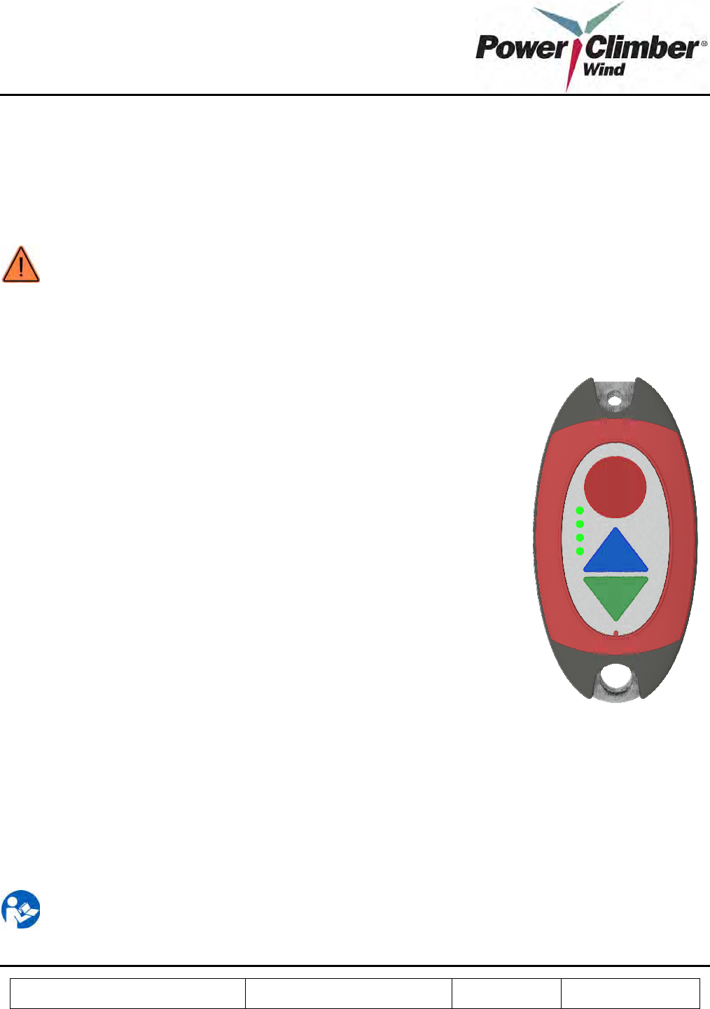
STOP
UP
DOWN
4. IBEX™ 1000 OPERATION INSTRUCTIONS
4.1 IBEX™ 1000 Features
WARNING: The IBEX™ 1000 climb assist system is not a safety device and must only be used in
conjunction with an independent personal fall arrest system.
4.2 Use of the EasyClimb Controller
To Set Level of Assistance
1. Press and hold the STOP button while:
a. Press and release the UP button to set the desired level of assistance for
ascent;
b. Press and release the DOWN Button to set the desired level of
assistance for descent.
2. When the desired levels are set, release the STOP button.
3. At first press, the indicator shows the current setting.
4. With further presses, the indicators will cycle.
Note: To ensure safe operation of the system;
• Pressing the STOP button prevents the assist motor from operating while
setting levels.
• Assist levels cannot be set during motor operation. Press STOP before
attempting to change assist level settings.
• Assist levels are retained after setting.
To Ascend
1. Couple the EasyClimb Controller between the harness chest ring and the rope grab clipped to the belt.
2. Press and release the UP button. The indicator flashes to show the set level of assist.
3. The belt will slowly start.
4. When the assist is felt, begin climbing up.
5. To stop, stop climbing then press the STOP button.
NOTE:
• If the level of assist does not reach 20 lbs within 1 second, the motor will stop. Restart by
pressing the UP button as above.
Reference: 702991-1 Issue date: 20-Dec-2008 Revision: A Page 20 of 25
This document and all copies are the property of Power Climber Wind. All dimensions and data are indicative only.
The user must ensure that the equipment complies with local rules and regulations.
• A stop delay is included and is preset to 10 seconds.
• The LED will show the selected level of assist during the climb.
To Descend
1. Connect the EasyClimb Controller between the harness chest ring and the rope grab clipped to the belt.
2. Press and release the DOWN button. The indicator flashes to show the set level of assist.
3. Begin climbing down.
4. To stop, stop climbing or press the STOP button.
NOTE:
• If the load in the EasyClimb Controller does not reach 20 lbs within 15 seconds, the motor will
stop. Restart by pressing the DEC button as above.
• The LED will show the selected level of assist during the climb.
To Stop
1. Stop climbing and the motor will disengage after 2 seconds, or press the STOP button to stop
immediately.
NOTE: You may have your weight on the EasyClimb Controller before pressing UP or DOWN.
To Shut Down the System
To shut down the system, put the power switch located on the electrical control box in the OFF position.
Miscellaneous
Often, during the ascent, it is necessary to momentarily stop, for example to open or close a hatch. For
convenience, a delay is automatically set when the climber stops climbing and the climber remains supported.
Provided the ascent resumes within 10 seconds, it is not necessary to press the UP button again, otherwise press
UP and resume the ascent.
Similarly, during descent, the climber may stop for a delay of 15 seconds before resuming the climb before it is
necessary to press the DOWN button. Otherwise press DOWN and resume the descent.
Because the climber is remote from the motor controls, and to ensure that the system responds to the climber’s
intentions and does not operate from unintended actions, it is necessary to press the UP or DOWN button to
initiate a climb.

Reference: 702991-1 Issue date: 20-Dec-2008 Revision: A Page 21 of 25
This document and all copies are the property of Power Climber Wind. All dimensions and data are indicative only.
The user must ensure that the equipment complies with local rules and regulations.
4.3 Safety
To ensure that operation of multiple EasyClimb Controllers does not cause unexpected actions, each EasyClimb
Controller has a unique serial number. Concurrent operation of more than one EasyClimb Controller in a tower
will cause the motor to stop and remain stopped for 30 seconds.
To prevent erroneous operations, it is only possible to communicate with the motor drive while the EasyClimb
Controller is pointed up.
To ensure that the EasyClimb Controller remains within its calibration limits, a procedure to recalibrate is
included in section 5.1. The user is strongly encouraged to understand the procedure and periodically carry out
recalibration.

Reference: 702991-1 Issue date: 20-Dec-2008 Revision: A Page 22 of 25
This document and all copies are the property of Power Climber Wind. All dimensions and data are indicative only.
The user must ensure that the equipment complies with local rules and regulations.
5. IBEX™ 1000 MAINTENANCE INSTRUCTIONS
The IBEX™ 1000 requires minimal maintenance. All bearings are sealed and do not require lubrication.
5.1 Periodic Inspection
Belt Inspection
As a moving part, the round assist belt is subject to wear with use. Visual inspection of the belt for abrasion or
other damage or weld separation should be performed regularly. Closer inspection of the entire belt length should
be performed once annually. Turning the key on the electrical control box will engage the maintenance mode. In
this mode, the motor will drive the belt at a slow speed. While at the ladder base, allow the belt to pass through
the inspector’s hand while also visually inspecting the belt as it moves.
Surface scarring from use of rope grabs is normal and will not affect performance or safety of the belt. However,
if excessive scarring or abrasion against the ladder or platforms is discovered, the worn section may be removed
and a replacement section spliced into place according to the belt splicing procedures in section 3.2.
Recalibration of EasyClimb Controller
During use it is possible that the EasyClimb Controller calibration will change from excessive loads being
applied. The following procedures will allow re-calibration without the aid of additional equipment.
Adjustment of ZERO:
1. Ensure that there is no load applied to the EasyClimb Controller other than the integrated rope grab.
2. Point the EasyClimb Controller vertically down so that the stop button is below the other buttons.
3. Press the STOP button and hold it for 5 seconds, then release.
4. The ZERO point is now calibrated.
Reference: 702991-1 Issue date: 20-Dec-2008 Revision: A Page 23 of 25
This document and all copies are the property of Power Climber Wind. All dimensions and data are indicative only.
The user must ensure that the equipment complies with local rules and regulations.
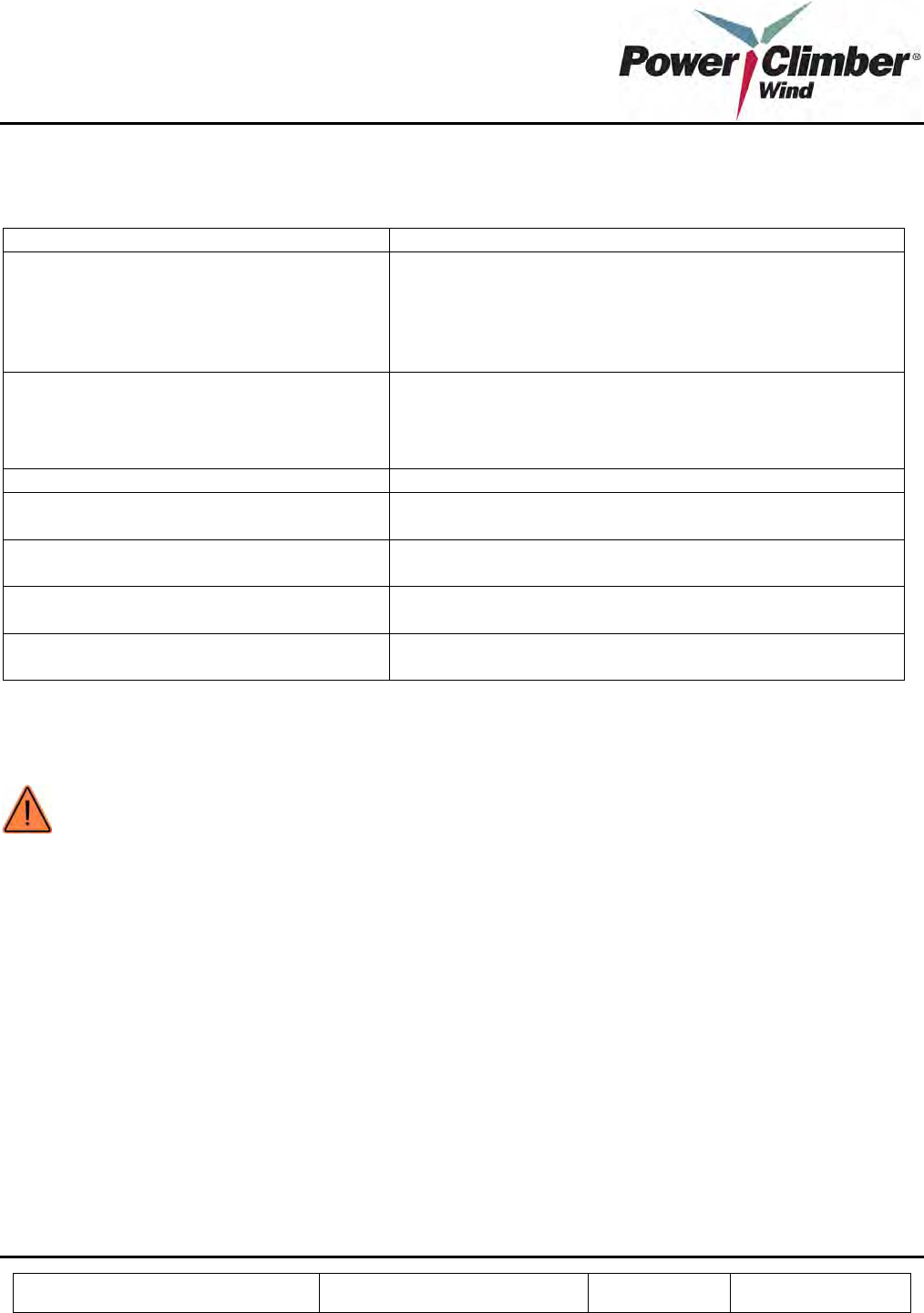
5.2 Troubleshooting
Symptom Consider
Belt weld is not correct as shown in Fig 9A • Review the belt splicing procedure in section 3.2
• Ensure that the temperature controller light has cycled at
least once before applying the iron.
• Ensure that the temperature controller light has cycled at
least twice before removing the iron.
Belt slips on the drive sheave • Check for oil on the belt or drive sheave. Use a dry
cloth to clean the belt using maintenance mode.
• Will occur if the belt tension is too low during
installation. See tension table in section 3.2.
Level of support provided seems low or high Carry out the calibration procedure in section 5.1.
EasyClimb Controller LEDs do not indicate Place the EasyClimb Controller on the charger for at least 24
hours
Belt stops when the EasyClimb Controller is
in the upper zone of the tower
Verify that the antenna is connected, correctly aligned and is
not damaged.
Belt will not respond to controller commands Ensure that the EasyClimb Controller is pointing up with the
stop button highest.
Belt stops at random times and will not
operate again for 30 seconds
Check to see if a second EasyClimb Controller is causing
interference.
5.3 Replacement of Damaged Components
WARNING: Only use parts supplied by Power Climber Wind. Use of non-authorized parts will void the
warranty.
Service of the EasyClimb Controller and electrical control box shall be performed by Power Climber Wind by
factory return. During the warranty period a replacement controller or control box will be supplied if required.
See the spare parts list in section 5.5 for replacement items.
Replacements are to be made following the installation procedure of section 3.
Reference: 702991-1 Issue date: 20-Dec-2008 Revision: A Page 24 of 25
This document and all copies are the property of Power Climber Wind. All dimensions and data are indicative only.
The user must ensure that the equipment complies with local rules and regulations.
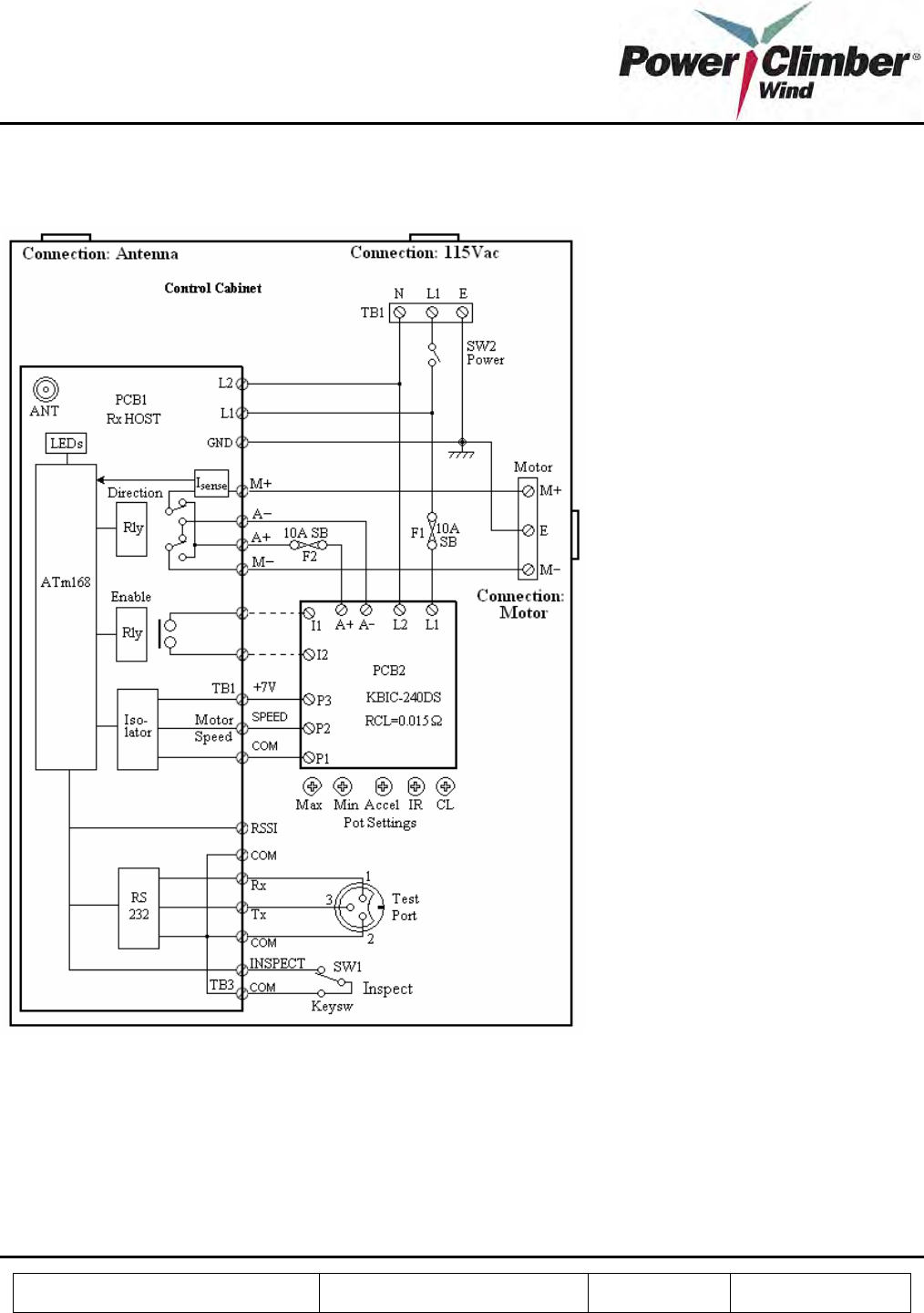
5.4 Electrical Schematics and Wiring Diagrams

Reference: 702991-1 Issue date: 20-Dec-2008 Revision: A Page 25 of 25
This document and all copies are the property of Power Climber Wind. All dimensions and data are indicative only.
The user must ensure that the equipment complies with local rules and regulations.
5.5 Spare Parts List
Part No. Description QTY
702299
Belt splicing toolkit (required for installation and
maintenance)
702953 Tool box 1
702954 Belt cutter 1
702947 Rope grabs 2
702956 Come-along 1
702957 Welding tool 1
702958 Dynomometer 1
702959 Thermometer 1
702960 Pipe hook 1
702946 Carabiner 1
Start-up Spares Kit (recommended per 50 units installed)
702301-1 Round reinforced polymer belt 500 ft
702303-1 1/2 HP Worm-gear PMDC motor 1
702963-1 Belt stabilizer ladder attachment kit (4 per kit) 1
702941-1 Receiver and motor drive control box 1
Additional Controller and Accessories
702952-1 EasyClimb Controller (w/o rope grab) 1
702947-1 Spring-loaded rope grab 1
702946-1 Oval twistlock carabiner 1
702945-1 Charger, 12V 1
5.6 Customer Service
For service requests or spare parts orders, contact Power Climber Wind Customer Service in the U.S. or Canada at
CustomerService@PowerClimberWind.com or via telephone at (877) PCWIND1.