Samsung Electro Mechanics SWB-A52H Wi-Fi Module User Manual SWB A51H Datasheet Preliminary
Samsung Electro Mechanics Wi-Fi Module SWB A51H Datasheet Preliminary
Contents
- 1. User Manual
- 2. Users Manual
User Manual

Samsung Electro-Mechanics Proprietary and Confidential
1/15
SWB-A52H Manual
Atheros AR6003X WLAN Solution
Samsung Electro-Mechanics
Summary
This manual presents the general information and user guide of SWB-A52H IEEE
802.11a/b/g/n Wireless LAN.
© 2012 Samsung Electro-Mechanics. All rights reserved
The names of actual companies and products mentioned
herein may be the trademarks of their respective owners.
No part of this document may be reproduced, stored in a
retrieval system, or transmitted in any form or by any
means without the express written consent of Samsung
Electro-Mechanics.
This document is subject to change without notice.

Samsung Electro-Mechanics Proprietary and Confidential
2/15
Table of Contents
1 GENERAL DESCRIPTION .................................................................................................... 3
1.1 FUNCTIONAL DESCRIPTION ....................................................................................................... 3
1.2 FEATURES ............................................................................................................................ 3
2 ELECTRICAL CHARACTERISTICS ........................................................................................ 5
2.1 DC CHARACTERISTICS ............................................................................................................. 5
3 RF SPECIFICATIONS .......................................................................................................... 6
3.1 RECEIVER RF SPECIFICATIONS FOR 2.4GHZ ................................................................................. 6
3.2 RECEIVER RF SPECIFICATIONS FOR 5GHZ .................................................................................... 7
3.3 TRANSMITTER RF SPECIFICATIONS FOR 2.4GHZ ............................................................................ 8
3.4 TRANSMITTER RF SPECIFICATIONS FOR 5GHZ ............................................................................... 9
4 ADDITIONAL INFORMATION ........................................................................................... 10
4.1 HOST INTERFACE CONFIGURATIONS .......................................................................................... 10
4.2 REFERENCE AND SLEEP CLOCK ................................................................................................. 12

Samsung Electro-Mechanics Proprietary and Confidential
3/15
1 General Description
1.1 Functional Description
SWB-A52H is the RF module that integrates Wireless LAN (WLAN). This embedded module is optimized
for WLAN enabled handheld mobile devices.
1.2 Features
IEEE Std 802.11a/b/g, 802.11n(1x1), HT=20/40 (HT=40, 5GHz ONLY)
WiFi direct support for2.4GHz only
Includes all the baseband and radio functionality, from host interface up to antenna, needs only
external antenna
Small dimensions (9.0 x 9.5 x 1.2 mm) with an LGA – 64pin peripheral footprint
Cellular coexistence supported
Host interfaces: SDIO, GSPI for WLAN.
RoHS compliant
MSL3
1.2.1 Radio Transceiver
Frequency of Operation: 2412 – 2472 MHz,
5180 – 5320 MHz, 5500 – 5700 MHz, 5745 – 5825 MHz
Fully compliant with IEEE 802.11a/b/g, 802.11n 1x1
Receiver sensitivity (< 8% PER) at 11 Mbit/sec data rate: -90dBm
Receiver sensitivity (< 10% PER) at 54 Mbit/sec data rate: -75dBm @ 11g
Receiver sensitivity (< 10% PER) at 54 Mbit/sec data rate: -74 dBm @ 11a
Receiver sensitivity (< 10% PER) at HT20, MCS7, 2.4GHz : -72dBm
Receiver sensitivity (< 10% PER) at HT20, MCS7, 5GHz : -71 dBm
Blocking filter for suppression of CDMA, GSM, PCS and WCDMA interfering signals
Transmitter output power in 802.11b mode at 1~11Mbps: 13dBm
Transmitter output power in 802.11g mode at 6~54Mbps: 13dBm
Transmitter output power in 802.11a mode at 6~54Mbps: 13dBm
Transmitter output power in 802.11n mode at HT20, 2.4GHz, MCS0~MCS7: 13dBm
Transmitter output power in 802.11n mode at HT20, 5GHz, MCS0~MCS6: 13dBm
Transmitter output power in 802.11n mode at HT40, 5GHz, MCS0~MCS5/MCS6: 13dBm/12dBm
1.2.2 Applications
Smart phone/feature phones with embedded WLAN connectivity

Samsung Electro-Mechanics Proprietary and Confidential
4/15
Tablet PC with embedded WLAN connectivity
Personal digital assistants (PDA)
SDIO WLAN Network Interface Cards (NIC)
Voice over IP (VoIP) cordless phones
Mobile gaming devices
Portable media players (PMP) including networked MP3 player
Networked digital camera and photo frames
Digital media adapter and receiver
Networked TV, set-top box, DVD recorder, personal video recorder (PVR), media drive, and
other consumer electronics appliances
Samsung Electro-Mechanics Proprietary and Confidential
5/15
2 Electrical Characteristics
2.1 DC Characteristics
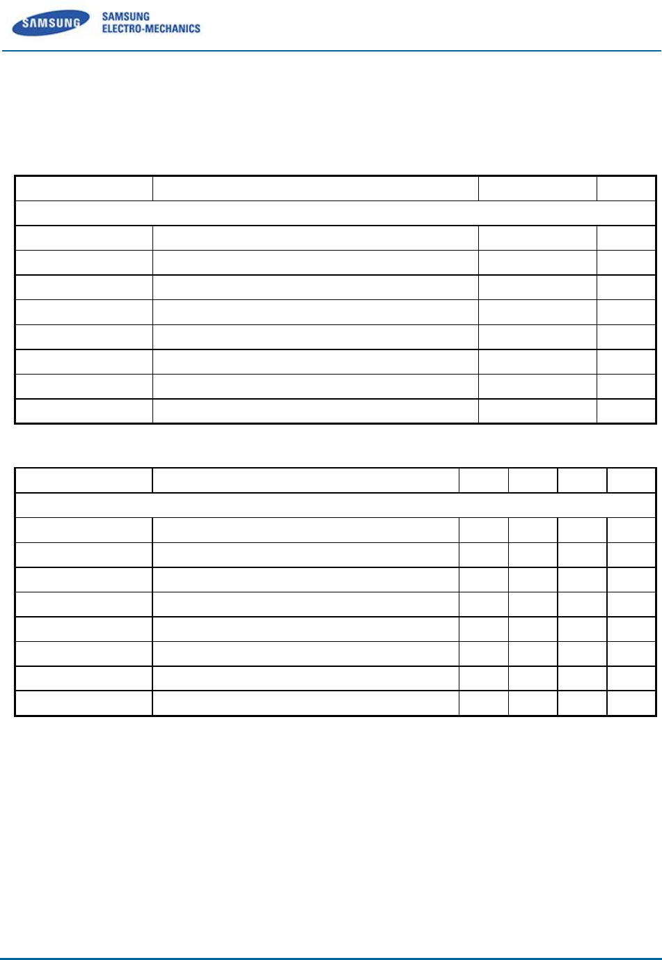
2.1.1 Absolute Maximum Ratings
Symbol(Domain)
Parameter
Max Rating
Unit
WLAN
VREG
Digital 1.8V supply
-0.3 to 2.5
V
AVDD18
Analog 1.8V supply
-0.3 to 2.5
V
DVDD_SDIO
SDIO I/O supply
-0.3 to 4.0
V
DVDD_SOC1
GPIO I/O supply
-0.3 to 4.0
V
DVDD_SOC2
GPIO I/O supply
-0.3 to 4.0
V
VDD33
3.3V supply
-0.3 to 4.0
V
VBATT
External PA supply
-0.3 to 4.8
V
PAREG_BASE
PAREG input
-0.3 to 4.0
V
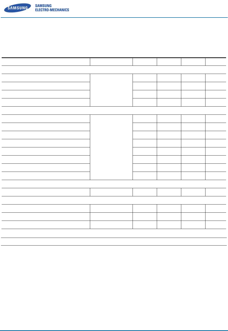
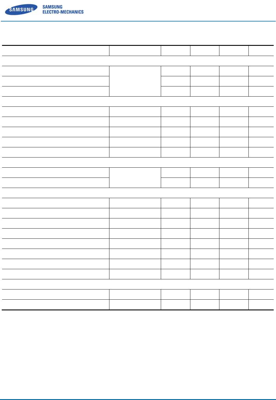
2.1.2 Recommended Operating Conditions
Symbol(Domain)
Parameter
Min.
Nom
Max
Unit
WLAN
VREG
Digital 1.8V supply
1.71
1.8
1.89
V
AVDD18
Analog 1.8V supply
1.71
1.8
1.89
V
DVDD_SDIO
SDIO I/O supply
1.71
3.46
V
DVDD_SOC1
GPIO0 I/O supply
1.71
3.46
V
DVDD_SOC2
GPIO1 I/O supply
1.71
3.46
V
VDD33
3.3V supply
3.14
3.3
3.46
V
VBATT
External PA supply
3.14
3.3
4.2
V
PAREG_BASE
PAREG input
3.14
3.3
3.46
V
Samsung Electro-Mechanics Proprietary and Confidential
6/15
3 RF Specifications
All measurements are made under nominal supply voltage and room temperature conditions.
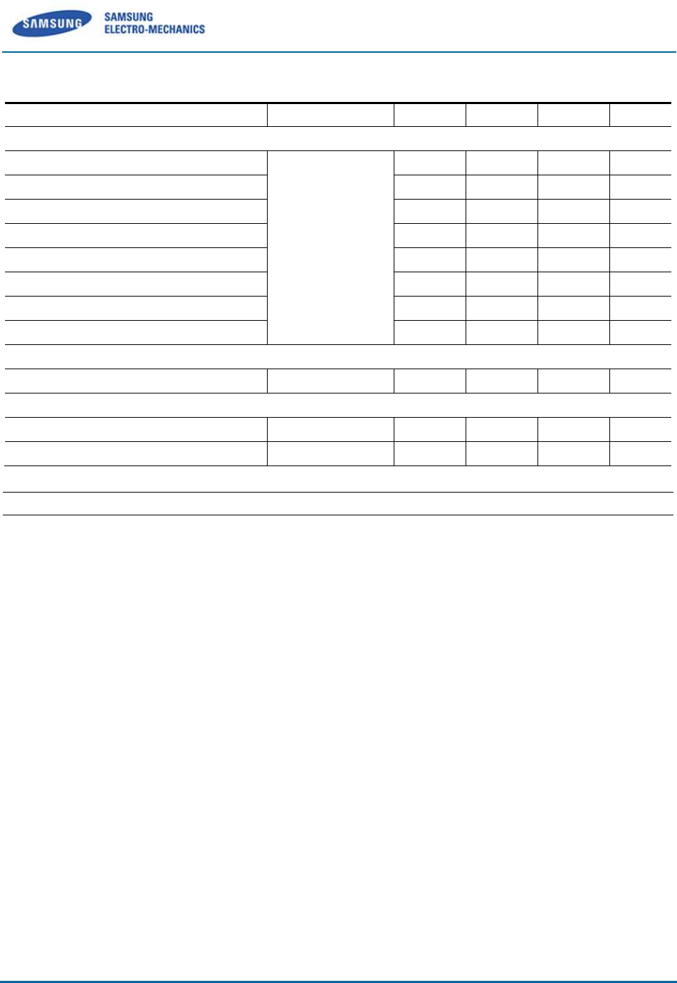
3.1 Receiver RF Specifications for 2.4GHz
Parameter
Conditions
Min.
Nom.
Max.
Unit
Minimum receiver sensitivity in 802.11b mode
1Mbps
PER<8%, Packet
size= 1024bytes
-80
dBm
2Mbps
-80*
dBm
5.5Mbps
-76
dBm
11Mbps
-90
-76*
dBm
Minimum receiver sensitivity in 802.11g mode
6Mbps
PER<10%,
Packet size=
1000bytes
-82*
dBm
9Mbps
-81*
dBm
12Mbps
-79*
dBm
18Mbps
-77*
dBm
24Mbps
-74*
dBm
36Mbps
-70*
dBm
48Mbps
-66*
dBm
54Mbps
-75
-65*
dBm
Minimum receiver sensitivity in 802.11n mode
HT20, MCS7, 1stream, 1Tx, 1Rx
PER<10%
-72
-64*
dBm
Maximum input signal level
802.11b mode
PER<8%
-10*
dBm
802.11g mode
PER<10%
-20*
dBm
802.11n mode
PER<10%
-20*
dBm
"*" indicates IEEE 802.11 standard specifications
Samsung Electro-Mechanics Proprietary and Confidential
7/15
3.2 Receiver RF Specifications for 5GHz
Parameter
Conditions
Min.
Nom.
Max.
Unit
Minimum receiver sensitivity in 802.11a mode
6Mbps
PER<10%,
Packet size=
1000bytes
-82*
dBm
9Mbps
-81*
dBm
12Mbps
-79*
dBm
18Mbps
-77*
dBm
24Mbps
-74*
dBm
36Mbps
-70*
dBm
48Mbps
-66*
dBm
54Mbps
-74
-65*
dBm
Minimum receiver sensitivity in 802.11n mode
HT20, MCS7, 1stream, 1Tx, 1Rx
PER<10%
-71
-64*
dBm
Maximum input signal level
802.11a mode
PER<10%
-30*
dBm
802.11n mode
PER<10%
-30*
dBm
"*" indicates IEEE 802.11 standard specifications
Samsung Electro-Mechanics Proprietary and Confidential
8/15
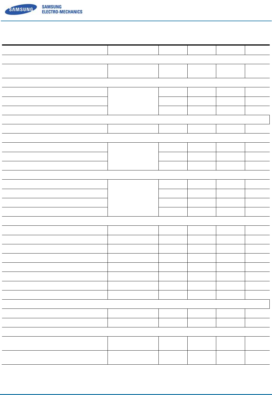
3.3 Transmitter RF Specifications for 2.4GHz
Parameter
Conditions
Min.
Nom.
Max.
Unit
Linear output power in 802.11b mode
Output power@1~11Mbps
As specified in
IEEE802.11
10
13
15
dBm
Linear output power in 802.11g mode
Output power@6~36Mbps
As specified in
IEEE802.11
10
13
15
dBm
Output power@48Mbps
10
13
15
dBm
Output power@54Mbps
10
13
15
dBm
Linear output power in 802.11n mode
Output power@HT20,MCS0 ~ MCS7
10
13
15
dBm
Transmit spectrum mask
Margin to 802.11b spectrum mask
Maximum output
power
0
dBr
Margin to 802.11g spectrum mask
0
dBr
Margin to 802.11n spectrum mask
0
dBr
Transmit modulation accuracy in 802.11b mode
1Mbps
As specified in
IEEE802.11b
-
35
%
2Mbps
-
35
%
5.5Mbps
-
35
%
11Mbps
-
35
%
Transmit modulation accuracy in 802.11g mode
6Mbps
Mandatory
-
-5
dB
9Mbps
Option
-
-8
dB
12Mbps
Mandatory
-
-10
dB
18Mbps
Option
-
-13
dB
24Mbps
Mandatory
-
-16
dB
36Mbps
Option
-
-19
dB
48Mbps
Option
-
-22
dB
54Mbps
Option
-
-29
-25
dB
Transmit modulation accuracy in 802.11n mode
HT20, MCS0~MCS6
dB
HT20,MCS7
-31*
-28
dB
Transmit power-on and power-down ramp time in 802.11b mode
Transmit power-on ramp time
from 10% to 90% output power
2
usec
Transmit power-down ramp time
from 90% to 10% output power
2
usec
* The method of full-packet estimation is applied.
Samsung Electro-Mechanics Proprietary and Confidential
9/15
3.4 Transmitter RF Specifications for 5GHz
Parameter
Conditions
Min.
Nom.
Max.
Unit
Linear output power in 802.11a mode
Output power@6~36Mbps
As specified in
IEEE802.11
10
13
16
dBm
Output power@48Mbps
10
13
16
dBm
Output power@54Mbps
10
13
16
dBm
Linear output power in 802.11n mode
Output power@HT20,MCS0 ~ MCS6
10
13
16
dBm
Output power@HT20,MCS7*
7
10
13
dBm
Output power@HT40,MCS0 ~ MCS5
10
13
16
dBm
Output power@HT40,MCS6
9
12
15
dBm
Output power@HT40,MCS7*
6
9
12
dBm
Transmit spectrum mask
Margin to 802.11a spectrum mask
Maximum output
power
0
dBr
Margin to 802.11n spectrum mask
0
dBr
Transmit modulation accuracy in 802.11a mode
6Mbps
Mandatory
-
-5
dB
9Mbps
Option
-
-8
dB
12Mbps
Mandatory
-
-10
dB
18Mbps
Option
-
-13
dB
24Mbps
Mandatory
-
-16
dB
36Mbps
Option
-
-19
dB
48Mbps
Option
-
-22
dB
54Mbps
Option
-
-29
-25
dB
Transmit modulation accuracy in 802.11n mode
HT20,MCS0~MCS5
dB
HT20,MCS6
-29
-25
dB
<Notice>
By enabling Full packet Estimation and changing Bias setting, AR6003X & SWB-A51H can pass -
28dB EVM target on MCS7. (The detailed information is furnished by QCA.)
Samsung Electro-Mechanics Proprietary and Confidential
10/15
4 Additional Information
4.1 Host Interface Configurations
4.1.1 WLAN Mode setting
HMODE0
Configuration
High (DVDD_SOC2)
SDIO Mode
GND
GSPI Mode
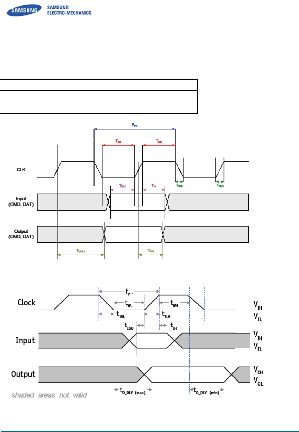
Figure 4-1 SDIO 2.0 timing
Figure 4-2 GSPI timing
Samsung Electro-Mechanics Proprietary and Confidential
11/15
SDIO Timing Constraints
Parameter
Description
Min.
Max.
Unit
Note
fPP
Clock frequency data transfer mode
0
50
MHz
40pF ≥ CL
tWL
Clock low time
7
-
ns
40pF ≥ CL
tWH
Clock high time
7
-
ns
40pF ≥ CL
tTLH
Clock rise time
-
10
ns
40pF ≥ CL
tTHL
Clock fall time
-
10
ns
40pF ≥ CL
tISU
Input setup time
6
-
ns
40pF ≥ CL
tIH
Input hold time
2
-
ns
40pF ≥ CL
tOH
Output hold time
2.5
-
ns
40pF ≥ CL
tO_DLY (min)
Output delay time
during data transfer mode
0
14
ns
40pF ≥ CL
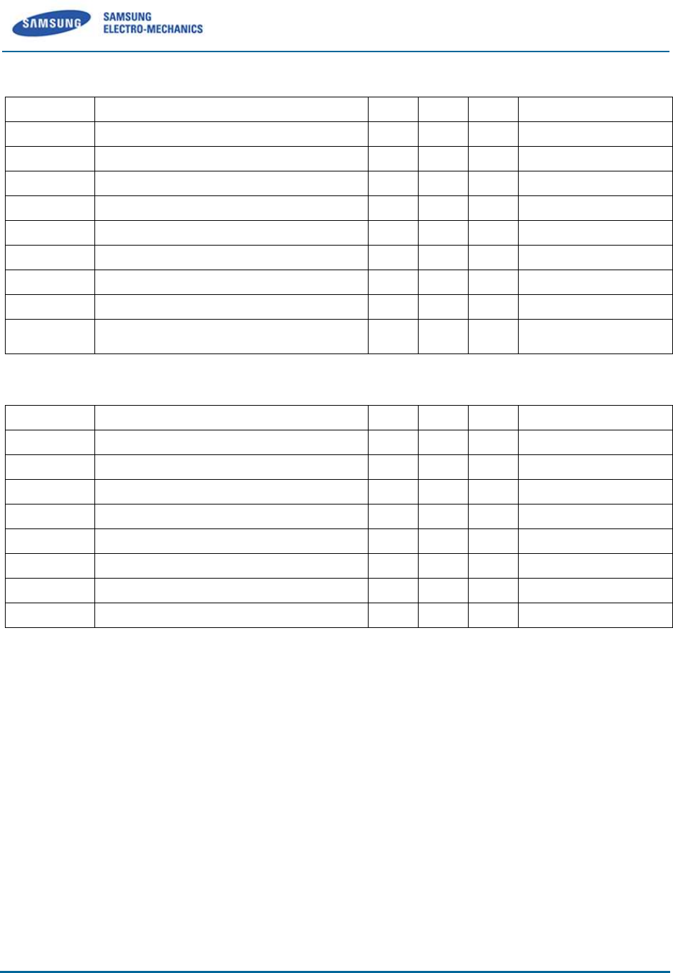
GSPI Timing Constraints
Parameter
Description
Min.
Max.
Unit
Note
fPP
Clock frequency
0
48
MHz
tWL
Clock low time
8.3
-
ns
tWH
Clock high time
8.3
-
ns
tTLH
Clock rise time
-
2
ns
tTHL
Clock fall time
-
2
ns
tISU
Input setup time
5
-
ns
tIH
Input hold time
5
-
ns
tO_DLY
Output delay
0
5
ns
Samsung Electro-Mechanics Proprietary and Confidential
12/15
4.2 Reference and Sleep Clock
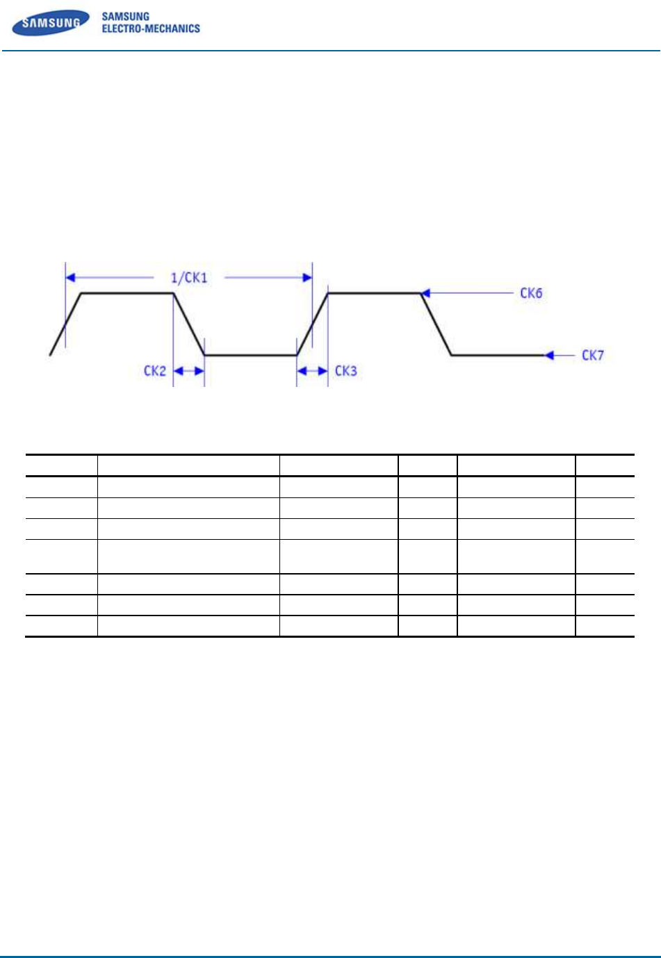
4.2.1 Optional External 32KHz Input Clock
The 32KHz clock is used in low-power modes such as IEEE power-save and sleep.
The SWB-A51H does not require an external 32KHz clock. By default, the SWB-A51H will utilize its
internal 32KHz clock. If the end application has a more accurate 32KHz clock, then it can be supplied
externally via the WIFI_CLK_32K pin. The WIFI_CLK_32K input clock timing and voltage requirements
are shown below.
Figure 4-5 WIFI_CLK_32K pin Input clock timing
Symbol
Description
Min.
Nom.
Max.
Unit
CK1
Frequency
-
32.768
-
kHz
CK2
Fall Time
1
-
100
ns
CK3
Rise Time
1
-
100
ns
CK4
Duty Cycle
(High-to-Low Ratio)
15
-
85
%
CK5
Frequency Stability
-50
-
50
ppm
CK6
Input High Voltage
V
CK7
Input Low Voltage
V
4.2.2 Reference Clock for WLAN
WIFI_XTALI and WIFI_XTALO are the pins used for the reference clock. The reference clock is the
primary clock source for the SWB-A51H. SWB-A51H supports 26MHz by default frequency.
and it can support 19.2/24/26/38.4/40/52MHz reference clock.
Reference clock source may come from either an external crystal or oscillator/TCXO source.
Three hardware solutions are used for the reference clock
- External crystal option
<Note> SEMCO recommend the below Crystal (CL=15PF) or equivalent
ITTI : 14340159-26.000MHz
SEMCO : SQ3D02600Y2JBA, SQBD02600Y2QCG, SQ2D02600Y2JCG,
HOSONIC : E1AB26.0000F15G11

Samsung Electro-Mechanics Proprietary and Confidential
13/15
NDK : EXS00A-CS04255 (NX2520_26MHz)
HARMONY : X3S026000BF1S
KDS : ZK05956
- External reference clock option (i.e. XO, VCXO, or VCTCXO)
- Host reference drive option
External Crystal Requirements
Parameter
Min.
Nom.
Max.
Unit
Frequency
-
26
-
MHz
Frequency Stability
-20
-
20
ppm
Effective series resistance (ESR)
-
100
Ohm
Capacitance (CL)
pF
The external reference clock option or host reference drive option voltage requirements are shown below.
Figure 4-6 External reference clock option or Host reference drive option
Symbol
Description
Min.
Nom.
Max.
Unit
CK2
Fall Time
-
-
0.1*Period
ns
CK3
Rise Time
-
-
0.1*Period
ns
CK4
Duty Cycle
(High-to-Low Ratio)
40
-
60
%
CK5
Frequency Stability
-20
-
20
ppm
CK6
Input High Voltage
0.75
3.46
V
CK7
Input Low Voltage
V
When using a TCXO, the clock signal is input at the WIFI_XTALO pin and must be AC-coupled using a
10nF capacitor. The WIFI_XTALI pin must be tied to GND when using a TCXO
Samsung Electro-Mechanics Proprietary and Confidential
14/15
FCC Notice
Host device of the approved module shall be marked with the following item:
Contains Transmitter Module FCC ID: E2XSWB-A52H or Contains FCC ID: E2XSWB-A52H
5.15- 5.25 GHz band is restricted to indoor operations only.
Compliance with FCC requirement 15.407(c)
Data transmission is always initiated by software, which is the passed down through the MAC,
through the digital and analog baseband, and finally to the RF chip. Several special packets are
initiated by the MAC. These are the only ways the digital baseband portion will turn on the RF
transmitter, which it then turns off at the end of the packet. Therefore, the transmitter will be on
only while one of the aforementioned packets is being transmitted. In other words, this device
automatically discontinues transmission in case of either absence of information to transmit or
operational failure.
This device complies with part 15 of the FCC Rules. Operation is subject to the following
two conditions: (1) This device may not cause harmful interference, and (2) this device
must accept any interference received, including interference that may cause undesired
operation.
FCC CAUTION
Changes or modifications not expressly approved by the party responsible for
compliance could void the user’s authority to operate the equipment.
This transmitter must not be co-located or operated in conjunction with any other antenna or
transmitter.
When installing it in a mobile equipment
This equipment complies with FCC radiation exposure limits set forth for an uncontrolled
environment and meets the FCC radio frequency (RF) Exposure Guidelines in Supplement C to
OET65. This equipment has very low levels of RF energy that it deemed to comply without

Samsung Electro-Mechanics Proprietary and Confidential
15/15
maximum permissive exposure evaluation (MPE). But it is desirable that it should be installed and
operated keeping the radiator at least 20cm or more away from person’s body (excluding
extremities: hands, wrists, feet and ankles).