Sargent A6761C Installation Instructions For 10G70 & 10G71 Electro Mechanical Bored Lock 1 3/4 Door With Elect
User Manual: Sargent Installation Instructions for 10G70 & 10G71 Electro-Mechanical Bored Lock for 1 3/4 door With Elect Instruction Sheets
Open the PDF directly: View PDF ![]() .
.
Page Count: 2
INSTALLATION INSTRUCTIONS FOR
10G70 & 10G71 Electro-Mechanical Bored Locks
for 1-3/4" Doors With ElectroLynx®Connector System
For installation assistance, contact SARGENT at 800-810-WIRE(9473) or www.sargentlock.com
4409-1 B
RELEASE DATE
TEMPLET NO.
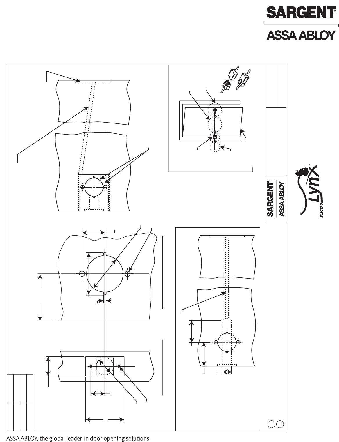
Inside/outside of door
Lock edge of door
3/8" dia.
Raceway
2-1/8" dia.
5/16" dia.
1 5/16"
(Typ.)
2-1/4"
1-1/8 "
1" dia.
13/16"
(Typ.)
(2 Places)
Hinge
Pigtail
Raceway
harness
Lock
Door with
raceway
ElectroLynx Connector system
Wood door applications
1 " Ref.
2-9/16" Ref.
2-15/32"
5/32"
Refer to page 2 for wiring instructions. All connections should be insulated.
2
Power requirement: 12V AC/DC, 0.50 amps or 24V AC/DC, 0.25 amps
BACKSET
2-3/4"
3-3/4"
5"
LOCKSET
10 Line
23-10 Line
25-10 Line
Backset
(see chart)
Backset:
See chart
16-APR-04
1
Prep directions:
Over-drill 1" dia.
to a depth of 2-9/16"
beyond backset to
create pocket for
ElectroLynx connectors
Metal door:
Prep for #8-32 unc
machine screws
Note:
Field modifications
to doors may alter
U.L. listed fire rating.
Provide pocket clearance
(approx. 1"x1") for
ElectroLynx connector system
(8-pin & 4-pin connectors)
10-Line bored-in lock door
manufacturer template
for solenoid functions
(2-3/4", 3-3/4" & 5" backsets)
See electric hinge
manufacturers' template
for mortise detail
1. Always make provision(s) to
protect electrical wires from abrasion
2. Minimum 3/4" dia. raceway to connect
from upper corner of reinforcement to
hinge pocket
ElectroLynx®
As part of their promise to provide innovative, fast and
effective, and higher security solutions to their customers,
ASSA ABLOY Group companies offer ElectroLynx, a
universal quick-connect system that simplifies the
electrification of the door opening.
ElectroLynx®is a registered trademark of ASSA ABLOY, Inc.
© SARGENT Manufacturing Company All rights reserved A6761C
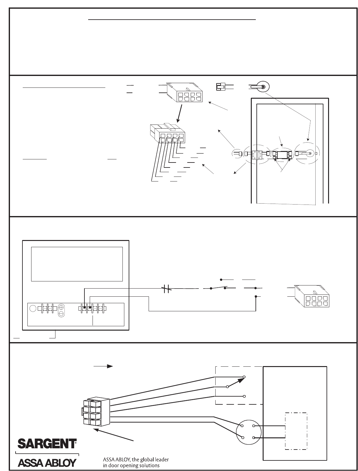
Sample wiring 10G70 Series Solenoid Locks with a 12VDC or 24VDC Regulated and Filtered Power Supply.
SARGENT offers both power supplies in 12VDC and 24VDC.
Wiring for RX-10G70/71 Series Solenoid locks. The lock is either 12VAC / VDC or a 24VAC / VDC lock body.
*Note: Wire 10G70 (Fail Safe) Locks to switch as shown
For 10G71 (Fail Secure) Locks, wire the switch with a
normally open contact to the red wire of the Pigtail Harness
Installation Notes: 10G70, 10G71, RX-10G70, RX-10G71
• Lockbodies are available with either 12V or 24V solenoid
• Solenoids require either 12V or 24V AC transformer or a filtered and regulated power supply
• Lockbodies have an in-line bridge rectifier
• RX- Lockbodies are handed (RH, RHR, LH, LHR)
• Doors manufactured by ASSA ABLOY Group Companies are available pre-wired with ElectroLynx
• Doors without ElectroLynx will have to be hard wired
• 10 Line solenoids are not polarity sensitive
C
NO
Pigtail Harness
(2 wires with 8-pin connector)
L N
Input
120VAC
60HZ
+ - + -
Output 1 Output 2
12VDC OR 24VDC
Regulated and Filtered
Power Supply
120VAC L/N/G
GND
NC
Normally Closed Fire
Alarm Contact
(If Required)
1
75
64
3
2
8
Red (+), 2
Black (-), 1
Switch or
relay contacts
*
Plug into
8-pin hinge
connector
at door
8-wire
QC8 Electric Hinge
with 8-pin connectors
Installation and wiring instructions
Wire colors remain consistent with all
ASSA ABLOY products
1. While installing the lock into the door,
plug the lock's 8-Pin connector into
the door's wire harness
2. Wire the Pigtail Harness to transformer
or power supply
3. Verify correct voltage is being used
CAUTION: The AC/DC voltage must not exceed
13.2 VOLTS FOR 12V LOCKS AND 26.4V for 24V
locks. If voltage exceeds this value, the lock
solenoid may be damaged.
4. Plug Pigtail Harness 8-pin connector into
electric hinge 8-pin connector
5. Test lock: Applying voltage unlocks
fail secure lock and locks fail safe lock
Pigtail Harness
(QC2 Shown) 2 wire with
8-pin connector)
1
75
64
3
2
8
Black (-)
Red (+)
Green
White
Orange
Brown
Yellow
Blue
1
75
64
3
2
8
Red (+), 2
Black (-), 1
These plug into
each other
Note: Typical door harness location is
shown. Other locations may exist
depending on door type.
10G70 or 10G71 lock with
8-pin connector. Lock is
not polarity sensitive.
Red, 2
Black, 1
The 4 pin
connectors are
not used in
this application
Door harness
with 8 & 4 pin
connectors
LOCK BODY
+
-
SOLENOID
IN LINE BRIDGE
RECTIFIER
POWER 12VAC / VDC
or a 24VAC / VDC Lockbody
(+) PIN 2 RED
(-) PIN 1 BLACK
RX SWITCH
C
NC
NO
RX SWITCH- MONITORS
INSIDE HANDLE
(HANDED)
WHITE
ORANGE
GREEN
8
5
7
2
4
6
1
3
C PIN 3 WHITE
NO PIN 4 GREEN
NC PIN 5 ORANGE
© SARGENT Manufacturing Company All rights reserved A6761C
