Savi Technology 65XSP-V1 Signpost SP-65X Series User Manual
Savi Technology Inc Signpost SP-65X Series
Contents
- 1. Users Guide
- 2. FCC Statements Revised
Users Guide

6DYL6LJQSRVW
63;6HULHV
,QVWDOODWLRQ*XLGH
9HUVLRQ
Published August 2004
Part number 805-04001-001 Rev. A
Documentation for Savi Signpost SP-65X Series version 1.0
Copyright © 2004 Savi Technology, Inc. All rights reserved.
Information in this manual is subject to change without notice and does not represent
a commitment from the vendor. The software and/or databases described in this
document are furnished under a license agreement or nondisclosure agreement. The
software and/or databases may be used or copied only in accordance with the terms
of the agreement. It is against the law to copy the software on any medium except as
specifically allowed in the license or nondisclosure agreement.
Savi, Savi SmartChain, SmartChain, and Batch Collection are registered trademarks,
and EchoPoint, Savi GateReader, Savi MobileReader, Savi Retriever, SaviReader,
SaviTag, Savi Technology, SmartSeal, UDAP, and Universal Data Appliance Protocol
and are trademarks of Savi Technology, Inc.
Other product names mentioned in this guide may be trademarks or registered
trademarks of their respective owners and are hereby acknowledged.
Savi Technology, Inc.
615 Tasman Drive
Sunnyvale, CA 94089-1707
Phone: 1-408-743-8000
Facsimile: 1-408-543-8650
www.savi.com

6DYL6LJQSRVW63;6HULHV,QVWDOODWLRQ*XLGH
&RQWHQWV
1,QWURGXFWLRQ
Features . . . . . . . . . . . . . . . . . . . . . . . . . . . . . . . . . . . . . . . . . . . . . 7
Savi Signpost SP-65X Series Description . . . . . . . . . . . . . . . . . . . 8
Specifications . . . . . . . . . . . . . . . . . . . . . . . . . . . . . . . . . . . . . . . . 10
Contacting Customer Support . . . . . . . . . . . . . . . . . . . . . . . . . . . 11
2+DUGZDUH,QVWDOODWLRQ
Materials and Equipment . . . . . . . . . . . . . . . . . . . . . . . . . . . . . . . 14
Signpost Connectors and LEDs . . . . . . . . . . . . . . . . . . . . . . . . . . 15
Preparing the Site . . . . . . . . . . . . . . . . . . . . . . . . . . . . . . . . . . . . . 16
Mounting the Savi Signpost SP-65X Series . . . . . . . . . . . . . . . . 17
Mounting the Signpost with Hardware . . . . . . . . . . . . . . . . . . 17
Mounting the Signpost with Mounting Feet . . . . . . . . . . . . . . 18
Installing External Ferrite Antennas . . . . . . . . . . . . . . . . . . . . 20
Connecting Power Cables to Savi Signpost SP-65X Series . . . . 20
Connecting Sync Cables to Savi Signpost SP-65X Series . . . . . . 21

6DYL6LJQSRVW63;6HULHV,QVWDOODWLRQ*XLGH
36LJQSRVW&RQILJXUDWLRQ
Communicating with the Signpost Using RS-232 . . . . . . . . . . . . 23
Adding and Configuring the Signpost in
SmartChain Site Manager . . . . . . . . . . . . . . . . . . . . . . . . . . . . . . . 24
Discovering a Signpost . . . . . . . . . . . . . . . . . . . . . . . . . . . . . . . 24
Adding a Signpost Manually Using an Ethernet Connection . . 26
Configuring Operation Settings Using Configuration Software . . 26
Configuring the UHF Reader Module in
SmartChain Site Manager . . . . . . . . . . . . . . . . . . . . . . . . . . . . . . . 27
Setting the Host IP Address and Synchronizing Time . . . . . . . 27
Sending UDAP Commands . . . . . . . . . . . . . . . . . . . . . . . . . . . . 28

6DYL6LJQSRVW63;6HULHV,QVWDOODWLRQ*XLGH
)LJXUHV
2-1 Removable link . . . . . . . . . . . . . . . . . . . . . . . . . . . . . . . . . . . 17
2-2 Attaching chain . . . . . . . . . . . . . . . . . . . . . . . . . . . . . . . . . . . 18
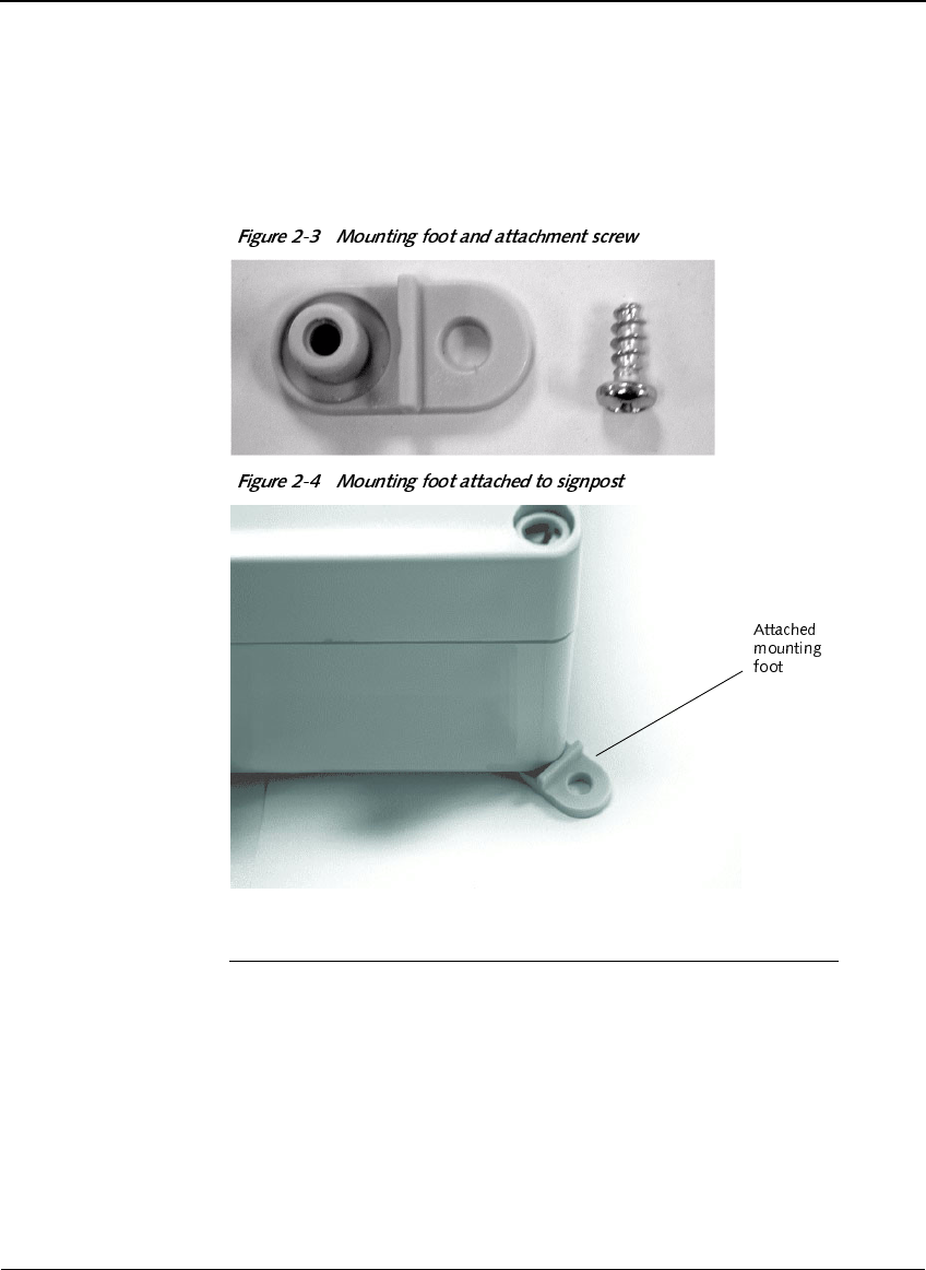
2-3 Mounting foot and attachment screw. . . . . . . . . . . . . . . . . . . 19
2-4 Mounting foot attached to signpost . . . . . . . . . . . . . . . . . . . . 19
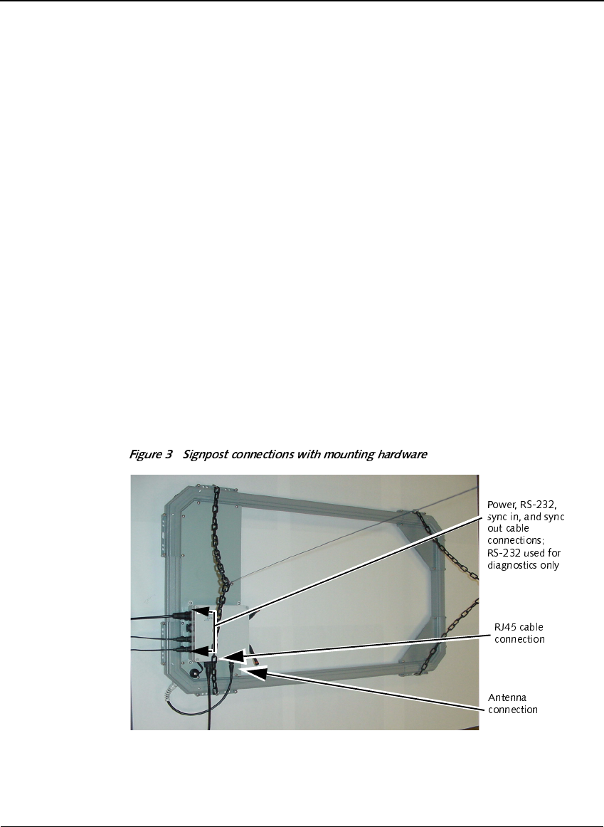
3 Signpost connections with mounting hardware. . . . . . . . . . . 20
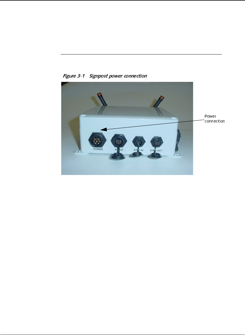
3-1 Signpost power connection . . . . . . . . . . . . . . . . . . . . . . . . . . 21
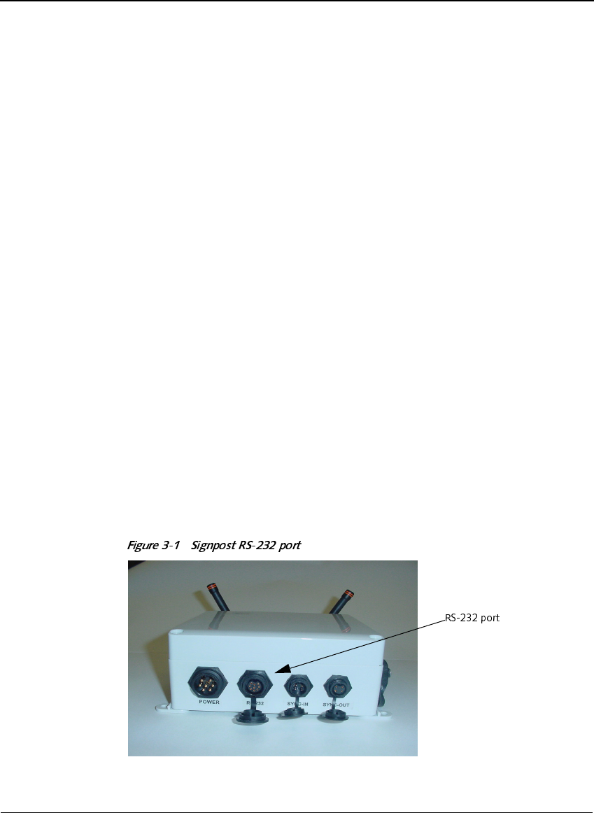
3-1 Signpost RS-232 port. . . . . . . . . . . . . . . . . . . . . . . . . . . . . . . 23

6DYL6LJQSRVW63;6HULHV,QVWDOODWLRQ*XLGH

&+$37(5
6DYL6LJQSRVW63;6HULHV,QVWDOODWLRQ*XLGH
,QWURGXFWLRQ
Savi Signpost SP-65X Series are short-range transmitters that provide their
identity information to all models of Savi® EchoPoint™ Series tags that are
within range. A tag uses this information to relay positional information
about itself to all models of Savi EchoPoint Series readers. The reader
forwards the collected data to the Savi SmartChain® Site Manager or
SmartChain Client Tools host platforms.
Savi Signpost SP-65X Series include a number of signpost models with
different capabilities and connectivity ranges. This series comprises the
basic signpost, signpost with network adapter, and signpost with network
adapter, reader, and ultra-high frequency (UHF) antenna.
Working with Savi readers, Savi Signpost SP-65X Series provide a
complete radio frequency identification (RFID) solution for real-time,
end-to-end visibility of goods and critical assets moving through the
supply chain.
)HDWXUHV
For specific models:
◆A short-range, low frequency inductive loop field generator triggers a
UHF transmission from Savi tags that pass through the field.
◆An optional UHF reader plug-in provides most Savi reader functionality
including UHF transmission of wake-up and command signals and
reception Savi tags responses.
◆An external ferrite rod antenna allows usage in compact, indoor areas
and for special applications.
◆An included network adapter allows the signpost to transmit reader data
to a local server, display diagnostics, and perform network maintenance
functions, such as firmware downloading. The network adapter is a
microprocessor module with RS-232 and Ethernet ports and runs
SaviNet, TCP/IP, and UDAP protocols.
&+$37(5
,QWURGXFWLRQ
6DYL6LJQSRVW63;6HULHV,QVWDOODWLRQ*XLGH
6DYL6LJQSRVW63;6HULHV
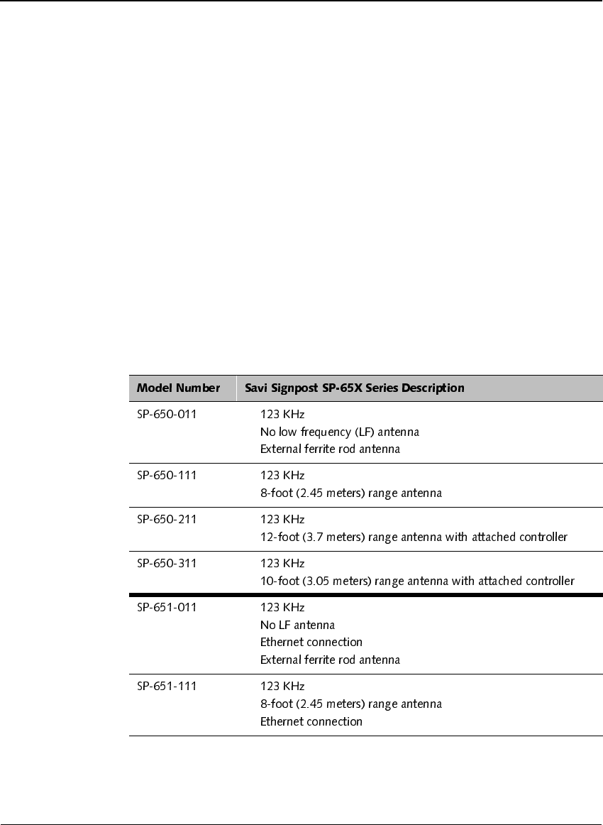
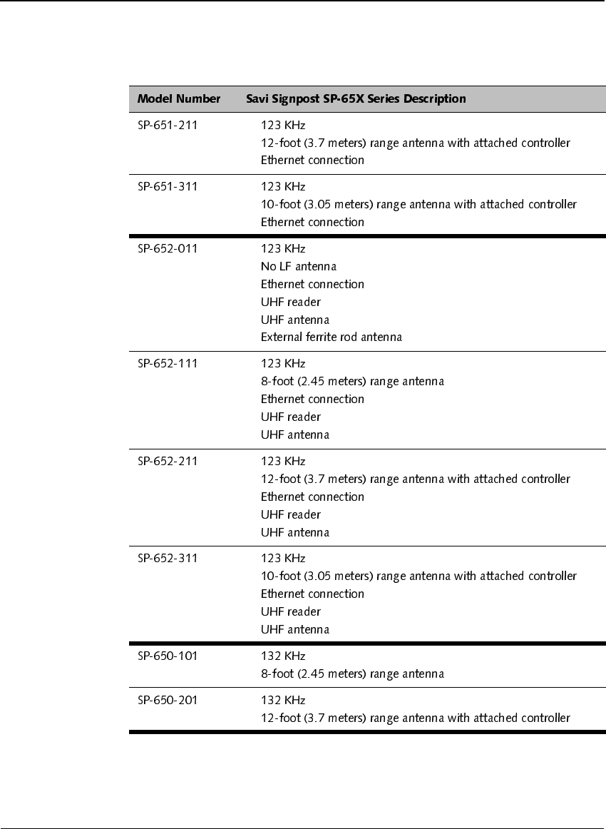
'HVFULSWLRQ
The following components comprise the Savi Signpost SP-65X Series:
◆Controller and network adapter unit
◆Antenna option that consists of:
❖Short-range ferrite rod inside controller unit; 8-foot (2.45 meters)
range
❖Mid-range air coil; 10-foot (3.05 meters) range
❖Long-range air coil; 12-foot (3.7 meters) range
◆Optional UHF reader plug-in
◆Optional external ferrite rod antenna
✦
✦
✦
✦
✦
✦
✦
✦
✦
✦
✦
✦
✦
✦
✦
✦
6DYL6LJQSRVW63;6HULHV'HVFULSWLRQ
6DYL6LJQSRVW63;6HULHV,QVWDOODWLRQ*XLGH
✦
✦
✦
✦
✦
✦
✦
✦
✦
✦
✦
✦
✦
✦
✦
✦
✦
✦
✦
✦
✦
✦
✦
✦
✦
✦
✦
✦
✦
✦
✦
&+$37(5
,QWURGXFWLRQ
6DYL6LJQSRVW63;6HULHV,QVWDOODWLRQ*XLGH
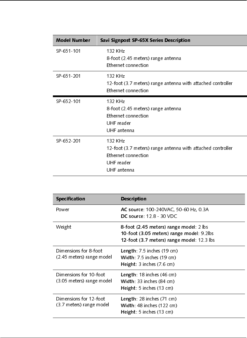
6SHFLILFDWLRQV
✦
✦
✦
✦
✦
✦
✦
✦
✦
✦
✦
✦
✦
✦
✦
✦

&RQWDFWLQJ&XVWRPHU6XSSRUW
6DYL6LJQSRVW63;6HULHV,QVWDOODWLRQ*XLGH
&RQWDFWLQJ&XVWRPHU6XSSRUW
If you cannot find the information you need in this guide, contact
Savi Customer Support.
◆Call 1-888-994-SAVI (North America only) or 1-408-743-8888 between
9 a.m. and 5 p.m. Pacific time.
◆Send email to help@savi.com.
◆Check http://www.savi.com/support for information.
When you contact Savi Customer Support by telephone or email, have the
following information available:
◆Contact information (company name, your name, email, and phone
number)
◆Problem description
◆Product type and location
◆Device model number
◆Software version
◆Serial number or license information

&+$37(5
,QWURGXFWLRQ
6DYL6LJQSRVW63;6HULHV,QVWDOODWLRQ*XLGH

&+$37(5
6DYL6LJQSRVW63;6HULHV,QVWDOODWLRQ*XLGH
+DUGZDUH,QVWDOODWLRQ
This chapter covers installing the Savi Signpost SP-65X Series hardware,
including the required tools and materials, site preparation, and making the
physical installation and power connections.
&+$37(5
+DUGZDUH,QVWDOODWLRQ
6DYL6LJQSRVW63;6HULHV,QVWDOODWLRQ*XLGH
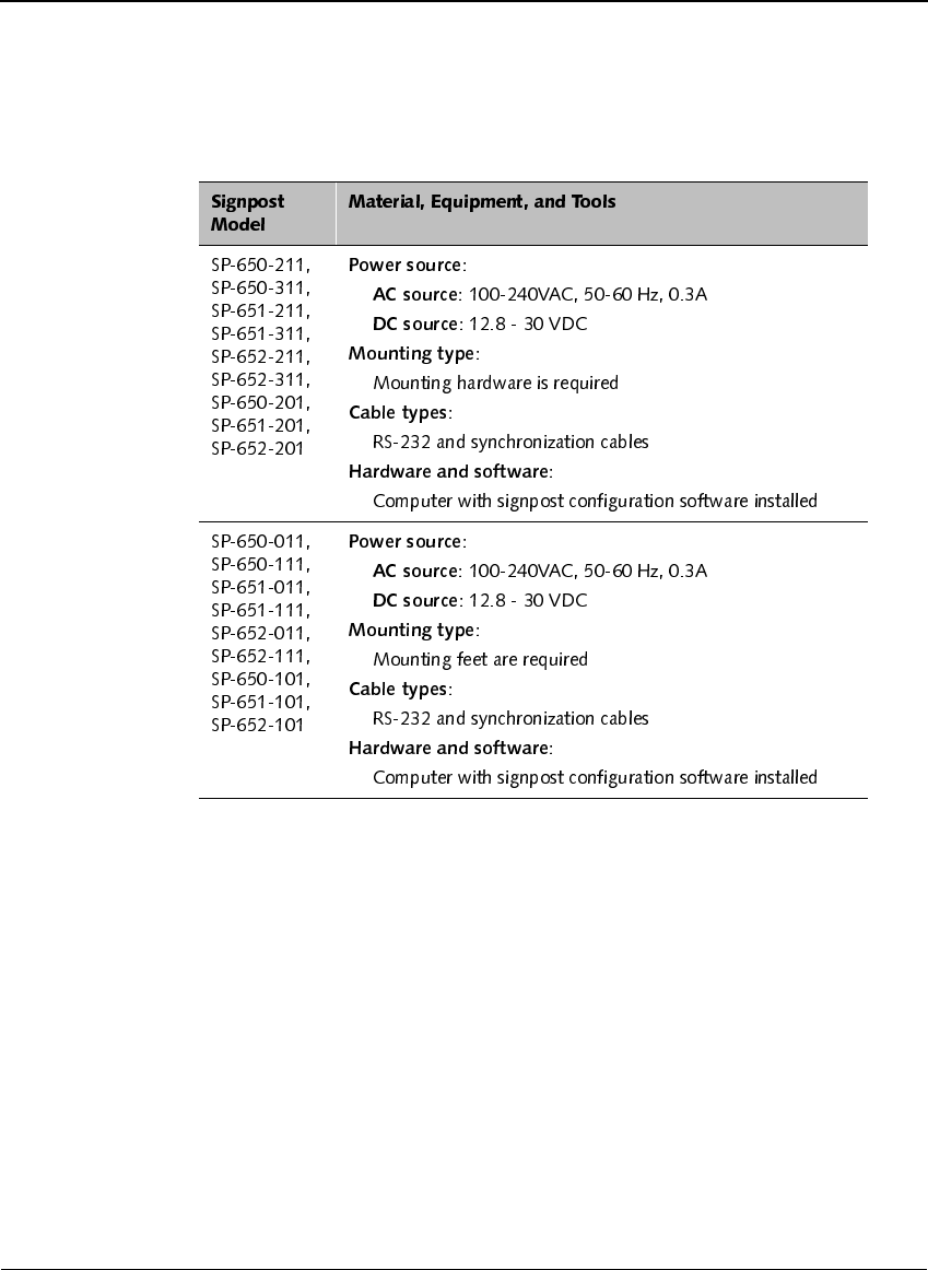
0DWHULDOVDQG(TXLSPHQW
✦
✦
✦
✦
✦
✦
✦
✦
✦
✦
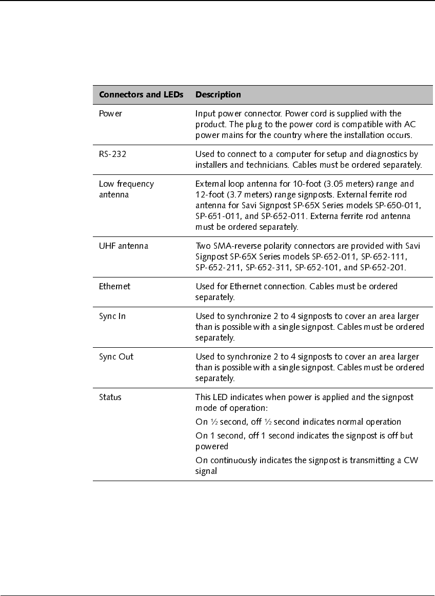
6LJQSRVW&RQQHFWRUVDQG/('V
6DYL6LJQSRVW63;6HULHV,QVWDOODWLRQ*XLGH
6LJQSRVW&RQQHFWRUVDQG/('V
&+$37(5
+DUGZDUH,QVWDOODWLRQ
6DYL6LJQSRVW63;6HULHV,QVWDOODWLRQ*XLGH
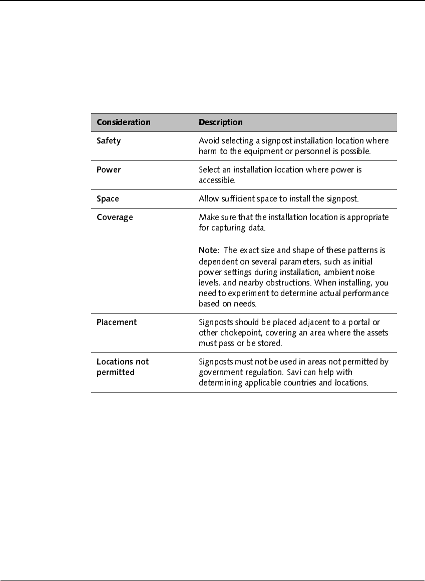
3UHSDULQJWKH6LWH
The criteria for placement and the preparation include the considerations
listed in the following table.
0RXQWLQJWKH6DYL6LJQSRVW63;6HULHV
6DYL6LJQSRVW63;6HULHV,QVWDOODWLRQ*XLGH
0RXQWLQJWKH6DYL6LJQSRVW
63;6HULHV
This section describes how to mount signposts with mounting hardware and
signposts with mounting feet.
0RXQWLQJWKH6LJQSRVWZLWK+DUGZDUH
Savi Signpost SP-65X Series models SP-650-211, SP-650-311, SP-651-
211, SP-651-311, SP-652-211, SP-652-311, SP-650-201, SP-651-201,
SP-652-201 can be hung adjacent to a portal or other chokepoint and must
use the supplied installation hanger kit.
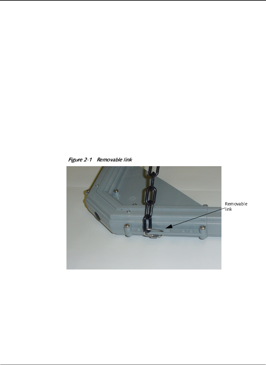
Attach a removable 1/8 inch (.33 cm) link to each of the four mounting
brackets at the four corners of the unit.
&+$37(5
+DUGZDUH,QVWDOODWLRQ
6DYL6LJQSRVW63;6HULHV,QVWDOODWLRQ*XLGH
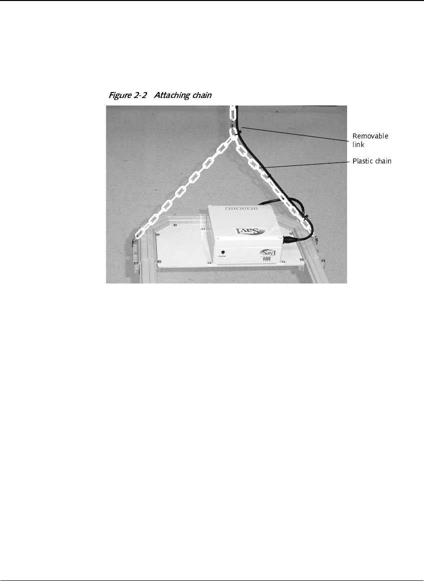
Using two lengths of plastic chain, attach each at both ends to the four
removable links, as shown in Figure 2-1 and Figure 2-2.
Attach another removable link to the center of the chain, as shown in
Figure 2-2.
Attach the top removable link to an appropriate rope, cable, or chain and
fasten to a 3/8 inch (.95 cm) eye screw or eye bolt (minimum 1-½ inch
(3.8 cm) penetration into solid material or through bolt).
Secure the power cord to the chain and route, as required.
0RXQWLQJWKH6LJQSRVWZLWK0RXQWLQJ)HHW
Savi Signpost SP-65X Series models SP-650-011, SP-650-111, SP-651-011,
SP-651-111, SP-652-011, SP-652-111, SP-650-101, SP-651-101,
SP-652-101 must be mounted with the supplied mounting feet.
Attach the mounting feet.
Figure 2-3 shows the mounting feet with the self-tapping screws that
attach them to the signpost.
0RXQWLQJWKH6DYL6LJQSRVW63;6HULHV
6DYL6LJQSRVW63;6HULHV,QVWDOODWLRQ*XLGH
Figure 2-4 shows a single mounting foot attached to the signpost. In this
case it is mounted at an angle, but the foot can be turned at different
angles.
Attach the mounting feet to the mounting surface.
1RWH
'2127DWWDFKWKHPRXQWLQJIHHWWRGU\ZDOORQO\XQOHVV
WKHGU\ZDOOLVEDFNHGE\VROLGVWUXFWXUDOPDWHULDO,I\RXPXVWXVH
WKLVPHWKRGVFUHZVQHHGWRSHQHWUDWHDPLQLPXPRILQFK
FPLQWRVROLGPDWHULDO
&+$37(5
+DUGZDUH,QVWDOODWLRQ
6DYL6LJQSRVW63;6HULHV,QVWDOODWLRQ*XLGH
,QVWDOOLQJ([WHUQDO)HUULWH$QWHQQDV
Savi Signpost SP-65X Series models SP-650-011, SP-651-011, and
SP-652-011 may be equipped with external ferrite rod antennas for indoor
use in compact areas or for special applications. If you are using two or
more external ferrite antennas, mount them at least 10 inches (25.4 cm)
apart. You mount the external ferrite antenna on a C-cross-section
aluminum (or other non-ferrous metal) rod, such as a handrail.
&RQQHFWLQJ3RZHU&DEOHVWR6DYL
6LJQSRVW63;6HULHV
Before you connect the Savi Signpost SP-65X Series power cable, be sure
to check relevant configuration, wiring diagrams, or applicable safety
regulations. The following table details the connectors and LEDs on all
models of the Savi Signpost SP-65X Series.
This section does not include connecting the signpost to a computer with a
serial cable for signpost software configuration. See Chapter 3, “Signpost
Configuration.”
Run the appropriate power cable to the signpost.
&RQQHFWLQJ6\QF&DEOHVWR6DYL6LJQSRVW63;6HULHV
6DYL6LJQSRVW63;6HULHV,QVWDOODWLRQ*XLGH
Connect the power cable to the signpost power connector, as shown in
Figure 3-1.
1RWH
7KHVRFNHWRXWOHWVKDOOEHLQVWDOOHGQHDUWKHHTXLSPHQWDQG
VKDOOEHHDVLO\DFFHVVLEOH
Continue with configuration using the signpost configuration software.
See “Configuring Operation Settings Using Configuration Software” on
page 26.
&RQQHFWLQJ6\QF&DEOHVWR6DYL
6LJQSRVW63;6HULHV
You connect sync cables to synchronize two to four signposts to cover an
area larger than is possible with a single signpost. Sync cables are ordered
separately.
Connect the female end of the cable to the Sync In connector of the
signpost.
Connect the male end of the cable to the Sync Out connector of another
signpost in the synchronized group.
Create group number assignments.
See “Configuring Operation Settings Using Configuration Software” on
page 26.

&+$37(5
+DUGZDUH,QVWDOODWLRQ
6DYL6LJQSRVW63;6HULHV,QVWDOODWLRQ*XLGH
&+$37(5
6DYL6LJQSRVW63;6HULHV,QVWDOODWLRQ*XLGH
6LJQSRVW&RQILJXUDWLRQ
You configure a signpost using SmartChain Site Manager and modify
specific signpost parameters with a signpost configuration software
application for Savi Signpost SP-65X Series. This chapter provides steps for:
◆Communicating with the signpost using RS-232
◆Adding and configuring the signpost in SmartChain Site Manager
◆Configuring the signpost settings using the configuration software
◆Configuring the UHF reader module for specific signposts in
SmartChain Site Manager
Before you connect and configure a signpost, you must install the signpost
configuration software application on the service computer.
&RPPXQLFDWLQJZLWKWKH6LJQSRVW
8VLQJ56
You use an RS-232 cable to connect the RS-232 port on the signpost to the
service computer. Disconnect this cable from the signpost and service
computer after you complete signpost configuration. Figure 3-1 shows the
RS-232 serial port for the Savi Signpost SP-65X Series.

&+$37(5
6LJQSRVW&RQILJXUDWLRQ
6DYL6LJQSRVW63;6HULHV,QVWDOODWLRQ*XLGH
$GGLQJDQG&RQILJXULQJWKH6LJQSRVW
LQ6PDUW&KDLQ6LWH0DQDJHU
To add a device to the network, you can use auto-discovery or add a
signpost manually. Whenever possible, Savi recommends using auto-
discovery to add a device.
'LVFRYHULQJD6LJQSRVW
(WKHUQHW&RQQHFWLRQ
The RJ-45 connector provides Ethernet connection for the Savi Signpost
SP-65X Series.
1RWH
5HSODFHDQGWLJKWHQWKHSURWHFWLYHFDSZKHQWKH5-SRUWLVQRW
XVHG
A signpost that is plugged into an Ethernet broadcasts discovery packets.
When you start a SmartChain Site Manager that is connected to the
Ethernet, it recognizes these broadcasts and responds to the signpost that a
SmartChain Site Manager at a given IP address is available for connection.
The signpost must reside on the same subnet mask as the SmartChain Site
Manager to be managed properly.
When a DHCP domain server is connected to the same network as the
SmartChain Site Manager and signpost, the signpost initiates a DHCP
operation to obtain a valid IP address to replace its default IP address
(10.7.19.11). If you are installing multiple signposts, it is a good idea to
connect one signpost to the network at a time to avoid IP address conflicts.
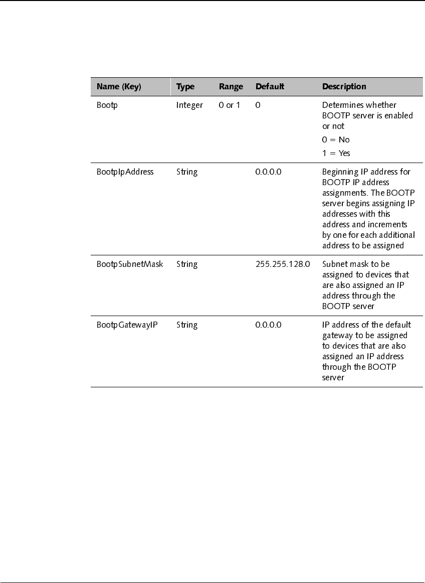
When a BOOTP domain server is connected to the same network as the
SmartChain Site Manager and signpost, the BOOTP server automatically
assigns an IP address to the signpost. The following four parameters must
be changed in SmartChain Site Manager to set up the BOOTP server.
$GGLQJDQG&RQILJXULQJWKH6LJQSRVWLQ6PDUW&KDLQ6LWH0DQDJHU
6DYL6LJQSRVW63;6HULHV,QVWDOODWLRQ*XLGH
To change the parameters for the BOOTP server:
Change the value of BootP from 0 to 1
This activates the BOOTP server.
Obtain an IP address or group of IP addresses from your Network
Administrator to change the value(s) of the BootpIpAddress(es) for
your signpost(s).
Set the subnet mask and gateway IP.

&+$37(5
6LJQSRVW&RQILJXUDWLRQ
6DYL6LJQSRVW63;6HULHV,QVWDOODWLRQ*XLGH
$GGLQJD6LJQSRVW0DQXDOO\8VLQJDQ
(WKHUQHW&RQQHFWLRQ
You can manually add a signpost that is plugged into an Ethernet by
assigning a static IP address. SmartChain Site Manager must have a TCP/IP
subnet that is compatible with the signpost’s default IP address (10.7.19.11).
The signpost should be connected to SmartChain Site Manager through a
hub, switch, or cross-over cable.
On the Windows desktop, click the Site Manager Console icon.
In the Network area of the console, right-click a protocol and select
Add Device.
Fill in the device properties.
&RQILJXULQJ2SHUDWLRQ6HWWLQJV
8VLQJ&RQILJXUDWLRQ6RIWZDUH
Before configuring signpost operation settings, you must connect a service
computer to the signpost. See “Communicating with the Signpost Using
RS-232” on page 23.
Configure the Signpost ID (1 to 65535).
The Signpost ID is a unique number in the facility. The signpost can be
identified in the system by associating this number with a description in
the SmartChain Site Manager configuration.
Program the transmit group number (0 to 3) for the signpost.
The factory setting is 0. The signpost will not synchronize when the
group number is set to 0. When you program a number from 1 to 3,
signposts having the same group number will transmit simultaneously.
Signposts having different group numbers will transmit independently.
Set the beacon control on/off.
You use the beacon control on/off option to program the beacon mode of
a tag. When this option is disabled, you cannot change the tag beacon
mode. When the option is enabled, you can change the tag beacon mode.

&RQILJXULQJWKH8+)5HDGHU0RGXOHLQ6PDUW&KDLQ6LWH0DQDJHU
6DYL6LJQSRVW63;6HULHV,QVWDOODWLRQ*XLGH
Set the low frequency power level.
For Savi Signpost SP-65X Series models SP-650-211, SP-651-211, and
SP-652-211 with the large air core antennas, you use the maximum
setting of 724, in compliance with international emissions standards. For
all other Savi Signpost SP-65X Series models, you use the maximum
setting of 1023.
Set the Tx mode to normal mode.
Verify the status of the signpost and that all signposts are compatible
with the system.
&RQILJXULQJWKH8+)5HDGHU0RGXOH
LQ6PDUW&KDLQ6LWH0DQDJHU
Savi Signpost SP-65X Series models SP-652-011, SP-652-111, SP-652-211,
SP-652-311, SP-652-101, and SP-652-201 must be configured over the
Ethernet connection and connected to SmartChain Site Manager.
The UHF reader module in all of these signpost models:
◆Allows you to send data from tags it receives once the host IP address is
set and the time is synchronized
◆Responds to tags that are triggered by the low frequency signpost signal
after a UDAP command is sent
6HWWLQJWKH+RVW,3$GGUHVVDQG6\QFKURQL]LQJ
7LPH
You can use the Network Manager to configure some properties of UDAP
devices that are also signposts embedded with the UHF reader module. You
can set the host and local IP addresses and other network information and
time synchronization parameters. You can also send some simple
commands such as UHVHW and FOHDU. To send more complex commands, use
the Send Commands dialog. See “Sending UDAP Commands” on page 28.
To set the host IP address and synchronize time:
On the desktop, click the Site Manager Console icon.
Click the Network Management button.

&+$37(5
6LJQSRVW&RQILJXUDWLRQ
6DYL6LJQSRVW63;6HULHV,QVWDOODWLRQ*XLGH
Select the device you want to configure.
Click Actions > Configure.
1RWH
,IWKHGHYLFHZDVGHWHFWHGE\DXWRGLVFRYHU\EHVXUHWR
FKDQJHWKHKRVW,3DGGUHVV7KLVPXVWEHWKH,3DGGUHVVRIWKH
6PDUW&KDLQ6LWH0DQDJHU
Click each tab and change the properties as necessary.
Click Apply or OK to record your changes.
6HQGLQJ8'$3&RPPDQGV
You can send UDAP commands to a selected device. The domain of UDAP
commands for a given device is defined in the device’s description
document.
On the Windows desktop, click the Site Manager Console icon.
To select a device, do one of the following:
◆In the Network area of the console, right-click a device name and
select Send Command.
◆Click the Network Management button, right-click a device name,
and select Send Command.
&RQILJXULQJWKH8+)5HDGHU0RGXOHLQ6PDUW&KDLQ6LWH0DQDJHU
6DYL6LJQSRVW63;6HULHV,QVWDOODWLRQ*XLGH
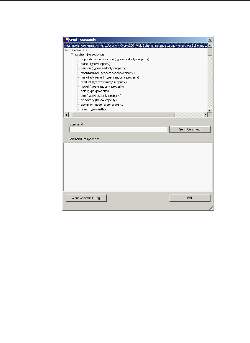
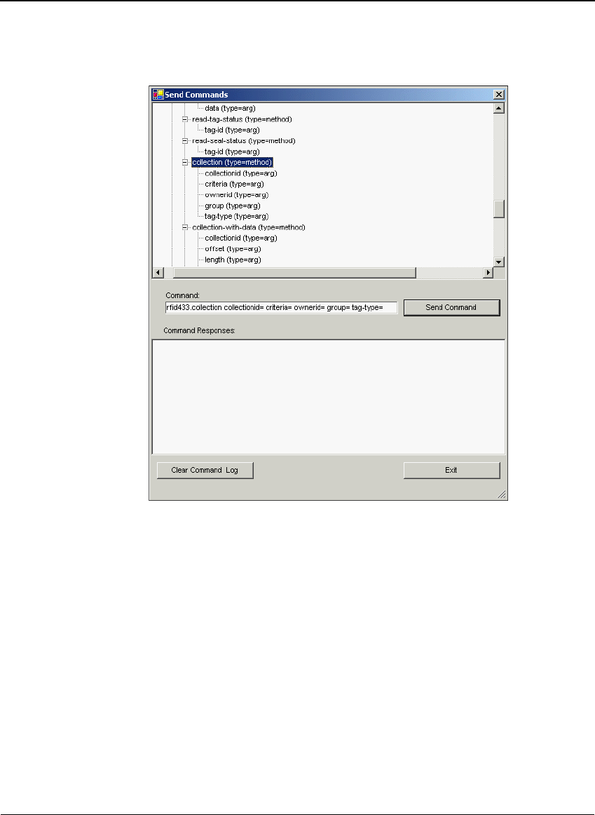
The top pane shows the device’s description document and the properties
and methods you can access by sending a UDAP command. This
provides a template for the UDAP command that you want to send. For
example, highlighting the method named FROOHFWLRQ automatically
creates a template of the command in the Command field.
&+$37(5
6LJQSRVW&RQILJXUDWLRQ
6DYL6LJQSRVW63;6HULHV,QVWDOODWLRQ*XLGH
Type the UDAP command you want to send in the Send Commands
dialog; for example, VHUYLFH"
Click Send Command.
The command response appears in the Send Command dialog.