Senao Co SL-2011CDPLUS Wireless LAN PC Card User Manual About AirLAN
Senao International Co Ltd Wireless LAN PC Card About AirLAN
Senao Co >
Contents
- 1. Users Manual Revised
- 2. DoC Statement
Users Manual Revised
Use r Gu id e
Before operating the unit, please read this manual thoroughly,
and retain it for future reference.
Wreless LAN Card
PLUS

Contents
1. Introduction 1
1.1 Package Contents 1
1.2 PC Card Description 1
1.3 System Requirements 2
1.4 Features and Benefits 2
1.5 Applications 2
1.6 Network Configurations 3
2. Installing Driver and Utility 7
2.1 Installation for Windows 95/98/ME/2000 7
2.2 Checking after Installation 9
2.3 Wireless LAN Client Utility 11
2.4 Uninstalling Driver and Utility 16
3. Connecting to a Network 17
3.1 Checking and Adding Client for Microsoft Networks 17
3.2 Checking and Adding NetBEUI 18
3.3 Checking and Adding TCP/IP 19
3.4 Checking and Adding File and Printer Sharing for Microsoft Networks 20
3.5 Checking and Adding Computer Name and Workgroup Name 20
4. Troubleshooting 21
Appendix A Specifications 24
Appendix B Regulatory Compliance Information 26
Appendix C Limited Warranty 28
Chapter 1 Introduction
This chapter describes the package contents, PC Card
description, system requirements, features & benefits,
applications and network configurations of SL-2011 PLUS
wireless LAN products.
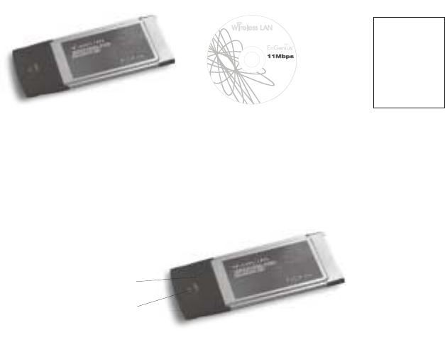
1-1 Package Contents
The PC Card package contains the following items as shown in
Figure 1-1
1. One PC Card
2. One Installation CD
3. One Quick Installation Guide
Figure 1-1
1- 2 PC Card Descriptions
The PC Card is a standard PC Card that fits into any PCMCIA Card
Type II slot. The PC Card has a LED indicator and a integrated built-in
diversity antenna as shown in Figure 1-2.
Figure 1-2
1. Integrated, with built-in diversity Antenna
2. Link LED
! 802.11 AdHoc mode – Blinking, no matter if the wireless LAN is connected
or not
! AdHoc mode – Solid GREEN, no matter the wireless is connected or not
! Infrastructure – Solid GREEN when the wireless is connected
! Off – No wireless activity
1
Wireless LAN PC Card
Quick Installation Guide
1
2
Insta llation CD
IEEE 802.11b

1- 3 System Requirements
Installation of the PC Card requires:
1. PC/AT compatible computer with PCMCIA Type II slot.
2. Windows 95/98/ME/2000 or Windows NT4.0 operating system environment.
3. Minimum 1.3M bytes free disk space for installing the PC Card driver
and utility program.
1- 4 Features and Benefits
11Mbps data rate High-speed data transmission
IEEE802.11b compliant
Fully interoperable with
IEEE802.11b compliant
products
Automatic data rate scaling at
11, 5.5, 2 and 1 Mbps Optimized throughput, range
and connectivity
64/128-bit WEP data
encryption/ decryption Powerful data security
Wide coverage range up to
400 meters in open space
Wireless connectivity for all your
computers
Advanced Power Management Extended battery life
Plug and Play PC Card
interface Easy installation
1- 5 Applications
The SL-2011 PLUS LAN products are easy to install and highly efficient.
The following list describes some of the many applications made
possible through the power and flexibility of wireless LANs:
1. Difficult-to-wire environments
There are many situations where wires can not or can not easily be laid.
Historic buildings, older buildings, open areas and across busy streets make
the installation of LANs either impossible or very expensive.
2. Temporary workgroups
Consider situations in parks, athletic arenas, exhibitions, disaster-recovery,
temporary office and construction sites where one wants a temporary WLAN
established and removed.
3. The ability to access real-time information
2
Doctors/nurses, point-of-sale employees, and warehouse workers can
access real-time information while dealing with patients, serving customers
and processing information.
4. Frequently changed environments
Show rooms, meeting rooms, retail stores, and manufacturing sites where
the workplace is frequently rearranged.
5. Small Office and Home Office (SOHO) networks
SOHO users need a cost-effective, easy and quick installation of a small
network.
6. Wireless extensions to Ethernet networks
Network managers in dynamic environments can minimize the overhead
caused by moves, extensions to networks, and other changes with wireless
LANs.
7. Wired LAN backup
Network managers implement wireless LANs to provide backup for
mission-critical applications running on wired networks.
8. Training/Educational Facilities
Training sites at corporations and students at universities use wireless
connectivity to ease access to information, information exchanges, and
learning.
1- 6 Network Configurations
To better understand how the SL-2011 PLUS wireless LAN products
work together to create a wireless network, it might be helpful to depict a
few of the possible SL-2011 PLUS network configurations. The SL-2011
PLUS wireless LAN products can be configured as:
1. Ad-hoc (or peer-to-peer) for departmental or SOHO LANs.
2. Infrastructure for enterprise LANs.
3. IP Sharing for 56K/ISDN TA/Cable/DSL Modem – Connect Internet and your
SOHO network.
Ad-hoc (peer-to-peer) Mode
This is the simplest network configuration that several computers
equipped with the PC cards that form a wireless network whenever they
are within range of one another (Figure 1-3). In ad-hoc mode, each
client, is peer-to-peer, would only have access to the resources of the
other client and requires no the access point. This is the easiest and
least expensive way for the SOHO to set up a wireless network.
3
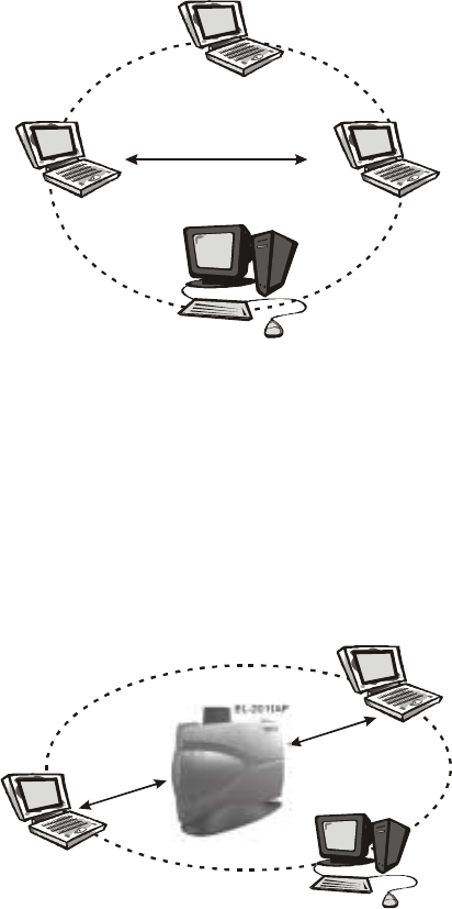
Figure 1-3 A wireless Ad-hoc network
Infrastructure Mode
The infrastructure mode requires the use of an access point (AP). In this
mode, all wireless communications between two computers have to be
via the AP no matter the AP is wired to Ethernet network or stand-alone.
If used in stand-alone, the AP can extend the range of independent
wireless LANs by acting a repeater, which effectively doubling the
distance between wireless stations as shown in Figure 1-4.
Figure 1-4
Extended-range independent WLAN using AP as repeater
4
W/ EL-2011CD
W/ EL-2011CD
W/ EL-2011CD
W/ EL-2011CD
L
Peer to Peer
W/ EL-2011CD
EL-2011AP
W/ EL-2011CD W/ EL-2011CD
L
L
Infrastructure
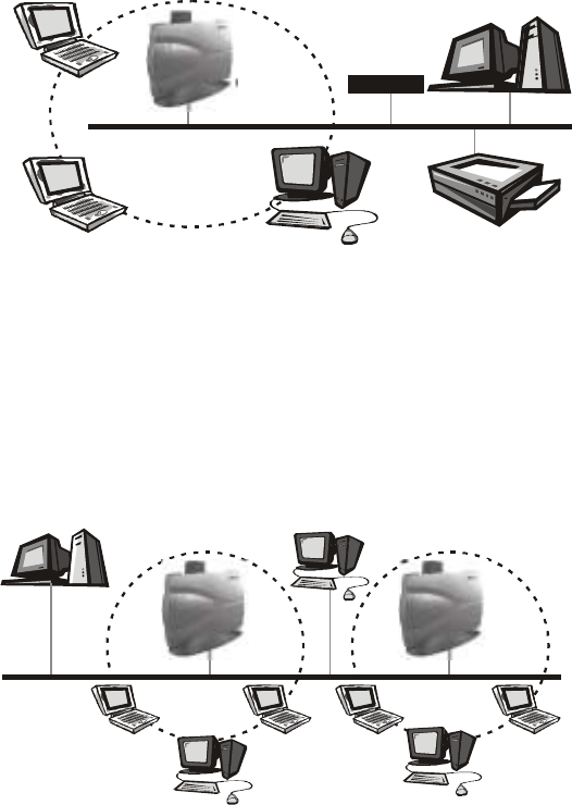
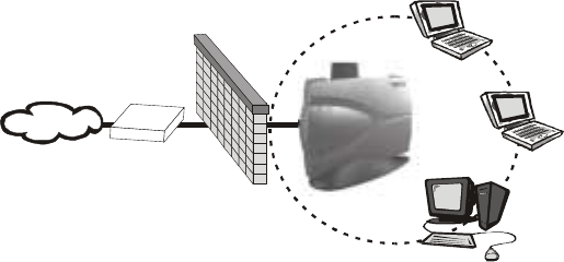
If wired to an Ethernet network as shown in Figure 1-5, the AP serves
as a bridge and provides the link between the server and the wireless
clients. The wireless clients can move freely throughout the coverage
area of the AP while remaining connected to the server. Since the AP is
connected to the wired network, each client would have access to
server resources as well as to other clients.
Figure 1-5 Single AP bridge
Access points have a finite range, on the order of 50 meters indoor and
100 meters outdoors. In a very large facility such as an enterprise, a
warehouse, or on a college campus, it will probably be necessary to
install more than one access point to cover an entire building or campus,
as shown in Figure 1-6. In this scenario, access points hand the client
off from one to another in a way that is invisible to the client, ensuring
unbroken connectivity. Wireless clients can roam seamlessly between
different coverage areas and remain connected to the network
Figure 1-6 Multiple-AP and roaming
5
W/ EL-2011CD
EL-2011AP
File server
Network Printer
W/ EL-2011CD
W/ EL-2011CD
Ent e rn e t
W/ EL-2011CD W/ EL-2011CD
W/ EL-2011CD
W/ EL-2011CD
File server
Enterprise
Ethernet
EL-2011AP EL-2011AP
Wireless Router and IP Sharing
In infrastructure mode, in addition to acting as a bridge between an
Ethernet and wireless network, the AP can be configured as a wireless
router and IP sharing device for Internet access as shown in Figure 1-7.
You don’t have to buy an expensive router. Nor you have to buy several
modems and setup phone lines. Just share one AP, one Modem, single
dial-up account, and one phone line, dozens of network users can go
surfing the Internet concurrently.
Figure 1-7 Wireless router and IP Sharing
6
W/ EL-2011CD
W/ EL-2011CD
W/ EL-2011CD
56K/ISDN TA/
Cable/ADSL Modem
Firewall
Internet
SOHO
EL-2011AP
Chapter 2 Installing Drivers & Client Utility
This chapter describes how to install the PC Card drivers and client
utility under Windows 95/98/ME/2000 and Windows NT4.0 environment.
2-1 Installation for Windows 95/98/ME/2000
During the installation, Windows 95/98/ME/2000 may need to copy
Windows systems files from the Windows 95/98/ME/2000 installation
diskette or CD-ROM. Therefore you will need a copy of the Windows
95/98/ME/2000 installation diskette or CD-ROM on hand before
installing the driver. On many systems, instead of a CD, the necessary
installation files are archived on the hard disk in C:\WINDOWS
\OPTIONS\CABS directory.
Installation Procedure:
1. Turn on your computer.
2. Be sure that there is no PCMCIA adapter inserted yet.
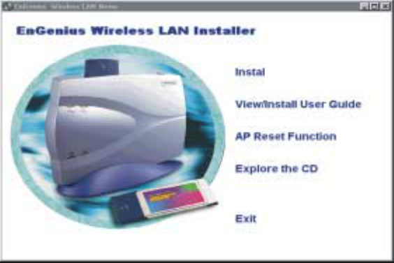
3. Insert the SL-2011 PLUS Wireless LAN Installation CD into your CD-ROM
drive. The setup program should start automatically as shown in Figure 2-1.
If it does not start, you can run it manually by selecting RUN from the Start
menu and running SETUP.EXE from CD-ROM drive.
Figure 2-1
7
SL-2011 PLUS
4. From SENAO Wireless LAN Installer, select Install SL-2011 PLUS PC Card.
Follow the instructions as they appear.
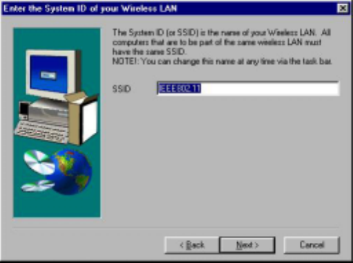
5. Enter the System ID (or SSID) of the Wireless LAN (default Network ID is
IEEE802.11) as shown in Figure 2-2. The SSID is the name of the Wireless
LAN Service Area of the wireless network to which your computer will
connect. The name you enter here must match exactly the name assigned to
the Access Point. Characters, capitalization, and spacing must be identical.
Figure 2-2
6. Select the Network Mode in which your wireless client will operate as shown
in Figure 2-3. If you are unfamiliar with Network Mode, refer to Chapter 1-6
Network Configurations for details. Follow the instructions as they appear.
7. Restart your computer.
8. Insert the PC Card into the PCMCIA slot of your computer.
9. Make sure that the network protocol parameters are set correctly for your
computer. These include the IP address, subnet mask, gateway and DNS. If
you are unfamiliar with how to set network protocol parameters, refer to
Chapter 3 Connection to Network for details.
10. Restart your computer for changes to take effect
8
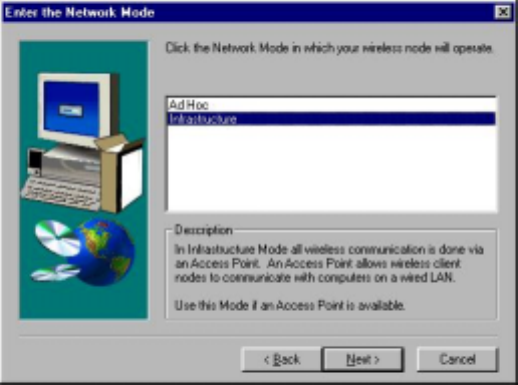
Figure 2-3
2- 2 Checking after Installation
After installing the driver and utility, follow the steps below to check that
the PC Card is operating correctly.
1. Click the Start button, select Settings, and then click Control Panel.
2. In the Control Panel window, double-click the System icon, then select the
Device Manager tab.
3. Double-click Network adapters, then select SL-2011 PLUS Wireless LAN
PC CARD as shown in Figure 2-4.
9
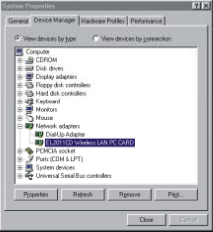
Figure 2-4
4. Click the Properties button, then check the message. This device is
working properly is displayed for Device status as shown in Figure 2-5.
5. If you find the Yellow (?) sign on the adapter or the above message is
not displayed, it shows the installation is not successful or SL-2011
PLUS is not operating properly. Uninstall and re-install the driver,
referring to Chapter 2-6 Uninstalling Driver and Utility.
10
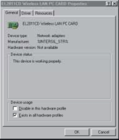
Figure 2-5
2-3 Wireless LAN Client Utility
Wireless LAN Client Utility is used to display or change the PC card
information about link, configuration, encryption, and
utility/driver/firmware version information. The client utility will also help
you with site selection. The client utility will be installed automatically
after installing the driver and utility. A new icon should appear in your
Icon tray. If the icon changes to red icon, it means the wireless LAN is
disconnected.
After finishing installing the driver and utility, the client utility will
automatically be executed and show a small green radio icon at the
right corner of Taskbar whenever the PC Card is inserted into the PC
Card slot of your computer. Double-click the radio icon to open the
Wireless LAN Client Utility window as shown in Figure 2-6. You can
click the tabs on the top of the windows to select various screen
messages. Below we explain the use and meanings of the various
screen messages.
11
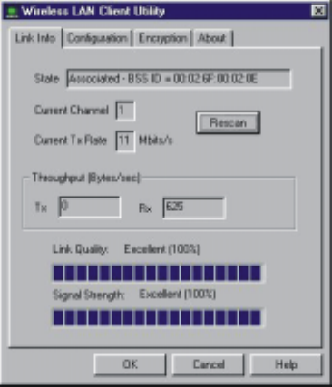
Figure 2-6
1. Link Info
State
Shows status information about the radio link, as shown in Figure 2-6
# Associated BSSID – means the wireless client is connected to an access
point. BSSID is shown in the form of six hex digits which is the MAC address
of the access point.
# Scanning – means the wireless client is searching for an available access
point in infrastructure mode.
# Disconnected – means there are no access points or other wireless
clients (if communicating in Ad-hoc mode), or the PC Card is unplugged in
your computer.
Current Channel
Shows the operation radio frequency channel that the wireless client is using
in infrastructure mode. In infrastructure mode, wireless client will always go
the same channel as their Access Point.
Current Tx Rate (Mbits/s)
The data speed that the wireless client is transmitting.
Throughput (Bytes/sec)
12
# Tx: shows the outgoing (sent) data speed.
# Rx: shows the incoming (received) data speed.
Link Quality
The bar shows the measured signal level and connection status. The higher
blue bar is, the better the radio signal is being received by the PC card.
Signal Strength
The bar shows signal strength level. The higher blue bar is, the more
powerful radio signal is received by the PC Card.
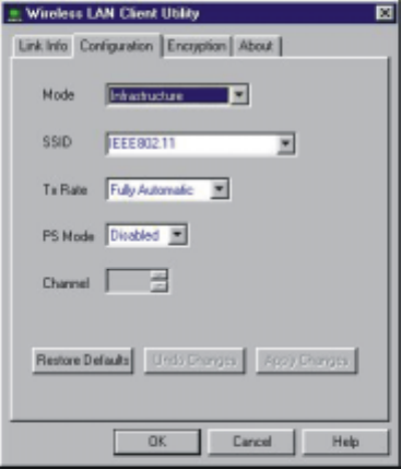
2. Configuration
Mode
Selects one of the following network mode, as shown in Figure 2-7.
Figure 2-7
# 802.11 AdHoc: this is the IEEE802.11 peer-to-peer mode of operation and
requires no Access Point. When wireless clients are operating in this
mode, all wireless clients require the same SSID and the channel number
is not important.
# AdHoc: this is non-standard peer-to-peer mode of operation and requires
no Access Point. When wireless clients are operating in this mode, all
wireless clients require the same channel number ,and the SSID is not
13
important
# Infrastructure: this mode of operation requires the use of an Access Point.
In this mode, all wireless communications between computers have to be
via the Access Point. (Default setting is Infrastructure)
SSID
SSID is an identification code required for communication in a wireless LAN.
You will only be able to connect with a wireless client (802.11 AdHoc) or an
Access Point (Infrastructure) which has the same SSID. If the SSID of a PC
Card is set as any, then the PC Card can connect to all available Access
Points. (Default setting is IEEE802.11)
Tx Rate
Select the transmission rate at which the data packets are transmitted by the
client. You can set this to Fully Automatic, 1Mbps, 2Mbps, Auto 1 or 2Mbps,
5.5Mbps, or 11Mbps. (Default setting is Fully Automatic)
PS Mode
Power saving management, disabled or enabled. (Default setting is
Disabled)
Channel
Select the operating radio frequency channel in 802.11 AdHoc or AdHoc
mode.
3. Encryption
If you require high security in transmission, you can select the 64 or
128-bit WEP (Wired Equivalent Privacy) key to encrypt data (Default
setting is Disable) as shown in Figure 2-8. WEP encrypts each frame
transmitted from the radio using one of the Keys from this panel. When
you use WEP to communicate with the other wireless clients, all the
wireless devices in this network must have the same encryption key or
passphrase.
14
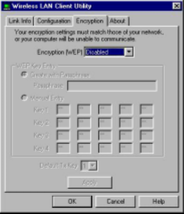
Figure 2-8
This panel allows the entry of keys or passphrases, which can then be
written to the driver and registry. Note that each key must consist of hex
digits, it means that only digit 0-9 and letters A-F are valid entries. If
entered incorrectly, program will not write the keys to a driver.
4. About
The About tab shows the product/driver/utility/PC Card firmware version
as shown in Figure 2-9. Users have to use this version number when
reporting their problems to technical support.
15
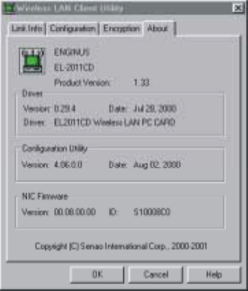
Figure 2-9
2- 4 Uninstalling Driver and Utility
If the PC Card installation is unsuccessful for any reason, the best way
to solve the problem may be to completely uninstall the PC Card and its
software and repeat the installation procedure again.
1. Click the Start button, select Program/SL-2011 PLUS, and then click
Uninstaller to uninstall the driver and utility. Uninstaller will automatically
uninstall and clear all drivers, utility, related settings installed previously.
16
Chapter 3 Connecting to a Network
This chapter describes how to prepare for connection to a network after
installing the PC Card drivers and utility.
The following is required for all computers if you want to connect to a
network.
1. Check Client for Microsoft Networks is installed
2. Check NetBEUI -> SL-2011 PLUS Wireless LAN PC Card installed.
3. Check TCP/IP -> SL-2011 PLUS Wireless LAN PC Card is installed.
4. Check file and printer sharing for Microsoft Networks.
5. Check computer name and workgroup name.
3-1 Checking and Adding Client for Microsoft
Networks
The Client for Microsoft Networks enables you to connect to other
Microsoft Windows computers and servers and use the files and printers
shared on them. If you works on Microsoft network environment, you
need to set up Client for Microsoft Networks.
1. After finishing installing the driver & utility and rebooting the computer as
described in Chapter 2. The computer will show a dialog box titled Enter
Network Password dialog box. Enter your password if it has been set or just
click Cancel.
2. Click the Start button, select Settings and then click Control Panel to open
the Control Panel window.
3. In the Control Panel window, double-click the Network icon to open the
Network dialog box.
4. Select the Configuration tab to check that Client for Microsoft Networks is
installed as shown in Figure 3-1. If not, click the Add button. Select Client
and click the Add button.
17
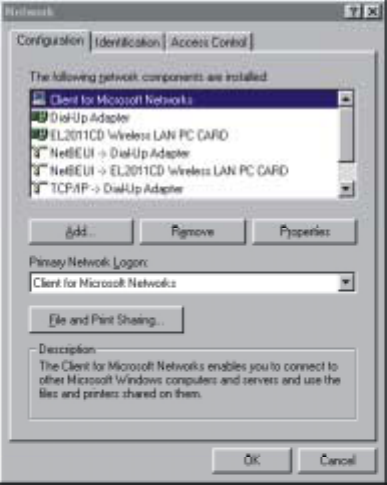
Figure 3-1
5. Select Microsoft for Manufacturer and Client for Microsoft Networks for
Network Client, and then click OK.
3-2 Checking and Adding NetBEUI
NetBEUI is a protocol you can use to connect to Windows NT, Windows
for Workgroups, or LAN Manager servers. If you work on Microsoft
network environment, you need to set up NetBEUI protocol.
1. Repeat the step 2 and 3 of Chapter 3-1 Checking and Adding Client for
Microsoft Networks.
2. Select the Configuration tab to check NetBEUI -> SL-2011 PLUS Wireless
LAN PC Card is installed. If no, click the Add button. Select Protocol and
click the Add button.
3. Select Microsoft for Manufacturer and NetBEUI for Network Protocol, and
then click OK.
18
3-3 Checking and Adding TCP/IP
TCP/IP is the protocol you use to connect to the Internet and wide-area
networks. If you want to connect to the Internet, you need to set up the
TCP/IP protocol.
1. Repeat the step 2 and 3 of Chapter 3-1 Checking and Adding Client for
Microsoft Networks.
2. Select the Configuration tab to check TCP/IP -> SL-2011 PLUS Wireless
LAN PC Card is installed. If not, click the Add button. Select Protocol and
click the Add button.
3. Select Microsoft for Manufacturer and TCP/IP for Network Protocol, and
then click OK.
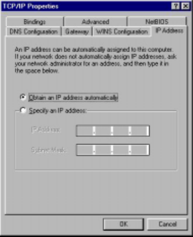
4. Double-click TCP/IP -> SL-2011 PLUS Wireless LAN PC Card to open
TCP/IP properties as shown in Figure 3-2. Due to different network
applications there are many different settings here. You can select either
Obtain an IP address automatically or Specify an IP address. If you use
the Specify and IP address, then you need to enter an IP address, Subnet
Mask, Gateway IP address, and DNS Server IP address for connecting to
Internet.
Figure 3-2
19
3-4 Checking and Adding File and Printer Sharing for
Microsoft Networks
File and printer sharing for Microsoft networks gives you the ability to
share your files or printers with Windows NT and Windows for
Workgroups computers. If you want to share your files or printers with
Microsoft networks, you need to set up this service.
1. Repeat the step 2 and 3 of Chapter 3-1 Checking and Adding Client for
Microsoft Networks.
2. Select the Configuration tab to check File and printer sharing for
Microsoft Networks is installed. If not, click the File and Printer Sharing
button.
3. In the File and Print Sharing window, select File and printer
sharing for Microsoft Networks, and then click OK.
4.
3-5 Checking and Adding Computer Name & Workgroup
Name
Windows uses the computer name and workgroup name to identify your
computer on the network. Please enter an unique name for your
computer, the workgroup it will appear in, and a short description of the
computer.
1. Repeat the step 2 and 3 of Chapter 3-1 Checking and Adding Client for
Microsoft Networks.
2. Select the Identification tab (Windows 98) or User Information tab (Windows
95) to check the computer name, workgroup and computer description are
entered. If not, enter a computer name, a workgroup name and then click OK.
The description field may be left blank. If you want to share data with other
persons, make sure you have the same workgroup name.
20

Chapter 4 Troubleshooting
This chapter describes the problems and corresponding solutions that
may occur when installing a PC Card.
Symptom Solution
Windows does not
detect the PC Card when
installed.
Verify that the PC Card is properly
inserted into the PC Card slot.
Check whether the computer has a
Plug and Play BIOS.
Windows 95/98/ME/2000 might not
detect the PC Card if a previous
installation of the PC Card was
cancelled before it was finished.
Remove the previous driver, and redo
the installation again.
Driver fails to load A resource conflict could exist.
For Windows 95/98/ME/2000, use the
Device Manager to resolve resource
conflicts.
Select System from the Control Panel,
then click on the Device Manager tab.
For Windows NT4.0, use the Service
Monitor entries in the System Log to look
for the conflicts. Use the NT diagnostics
program to locate free resources.
21

Device conflict on a
Windows system
A device conflict under Windows
95/98/ME/2000/NT may be related to
the PC Card.
For Windows 95/98/ME/2000, use the
Computer properties to identify the
used I/O port addresses and IRQ
values.
For Windows NT4.0, use the Windows
NT diagnostics program to detect the
cause of the card conflict and to deter-
mine unused I/O port addresses and
IRQ values.
If there is a device conflict, select
alternative settings for I/O Base Address
or IRQ values. If you know which device
is conflicting with the PC Card, you have
the option of changing that device’s I/O
address or IRQ instead of changing the
PC Card.
No resource conflicts were
detected, but the wireless
station does not attach to
the network
Verify that the SSID of the PC Card
matches that of the access point. Use
the Network Configuration Properties
Application in the Control Panel to
modify the SSID.
Verify that the Network Mode of the
PC Card is configured correctly.
22

Nonfunctioning card LED
The PC Card is not powered on. The
cause may be:
# No Driver loaded or installed.
# Card – Driver mismatch which
prevented the driver from loading.
# Device conflict which prevented the
driver from loading.
Actions:
# Verify that a driver has been installed.
# Determine if there is a conflict with
another device.
Weak signal or
intermittent connection.
Try reorienting the antenna. The PC
Card antenna is attached to the end
of the PC Card. For best use of the
antenna:
Keep the area around the antenna
clear from materials that could block
radio transmission, such as metal
objects, electronic devices, and
cordless telephones.
If your signal is weak, change the
direction of the antenna slightly.
If necessary, move your notebook
computer a few inches to find a better
signal.
Use the Link Quality and Signal Strength
display in the Client Utility to determine
the best location and orientation for a
network connection.
23

Appendix A Product Specifications
General
Radio Data Rate 11, 5.5, 2 and 1 Mbps, Auto Fall-Back
Range (open environment)
11 Mbps – 150m
5.5 Mbps – 200m
2 Mbps – 250m
1 Mbps – 400m
Operating Voltage 3.3V
EMC Certifications FCC Part 15, ETSI 300/328
Compatibility Fully interoperable with IEEE802.11b
compliant products
LED Indicator RF Link activity
Network Information
Network Architecture Support ad-hoc, peer-to-peer
networks and infrastructure
communications to wired Ethernet
networks via Access Point
Drivers Windows 95/98/ME/2000/NT 4.0
Access Protocol CSMA/CA
Roaming IEEE802.11b compliant
Security 64/128-bit WEP data encryption
Radio
Frequency Band 2.4 – 2.4835 GHz
Radio Type Direct Sequence Spread
Spectrum (DSSS)
Modulation CCK (11, 5.5Mbps)
DQPSK (2Mbps)
DBPSK (1Mbps)
Operation Channels 11 for North America, 14 for Japan,
13 for Europe, 2 for Spain, 4 for
France
RF Output Power 20dBm
Antenna Integrated, with built-in diversity
Sensitivity @FER=0.08 11 Mbps < -83dBm
5.5 Mbps < -86dBm
2 Mbps < -89dBm
1 Mbps < -91dBm
24

Environmental
Temperature Range 0 to 50 C (operating)
-20 to 80 C (storage)
Humidity (non-condensing) 5% to 95% typical
Physical Specifications
Form Factor PCMCIA Type II PC Card
Dimensions 118(L) mm x 54(W) mm x 7.5(H) mm
Weight 40 g
25
Appendix B
Regulatory Compliance Information
IMPORTANT NOTE
Radio Frequency Interference Requirements
This device complies with Part 15 of FCC Rules and Canada RSS-210.
Operation is subject to the following conditions:
1. This device may not cause harmful interference.
2. This device must accept any interference received, including interference that
may cause undesired operation.
3. To comply with RF safety requirements, you must maintain a distance of 20
cm from the antenna when operating the device.
4. This transmitter must not be co-located or operating in conjunction with any
other antenna or transmitter.
Interference Statement
‧User Manual must provide user information in accordance With
§15.21, 15.27 and 15.105(b):
Instruction Manual
Federal Communication Commission Interference Statement
This equipment has been tested and found to comply with the limits for
a Class B digital device, pursuant to Part 15 of the FCC Rules, These
limits are designed to provide reasonable protection against harmful
interference in a residential installation. This equipment generates, uses
and can radiate radio frequency energy and, if not installed and used in
accordance with the instructions, may cause harmful interference to
radio communications. However, there is no guarantee that interference
will not occur in a particular installation. If this equipment does cause
harmful interference to radio or television reception, which can be
determined by turning the equipment off and on, the user is encouraged
to try to correct the interference by one of the following measures:
$ Reorient or relocate the receiving antenna.
$ Increase the separation between the equipment and receiver.
$ Connect the equipment into an outlet on a circuit different from that to which
the receiver is connected.
$ Consult the dealer or an experienced radio/TV technician for help.
FCC Caution: To assure continued compliance, (example – use only
shielded interface cables when connecting to computer or peripheral
devices). Any changes or modifications not expressly approved by the
party responsible for compliance could void the user’s authority to
operate this equipment.
27
Appendix C Limited Warranty
HARDWARE
SENAO Technologies Inc. (“SENAO”) warrants its products to be free
from defects in workmanship and materials, under normal use and
service, for the following length of time from the date of purchase from
SENAO or its authorized reseller:
$ One (1) years for the PC Cards.
$ One (1) year for the Access Points
If a product does not operate as warranted during the applicable
warranty period, SENAO will, at its option and expense, repair the
defective product or part, or deliver to Customer an equivalent product
or part to replace the defective item. All products that are replaced will
become the property of SENAO. Replacement products or parts may be
new or reconditioned. SENAO warrants any replaced or repaired
product or part for ninety (90) days from shipment, or the remainder of
the initial warranty period, whichever is longer.
SOFTWARE
Software and documentation materials are supplied as is without
warranty as to their performance, merchantability, or fitness for any
particular purpose. However, SENAO warrants the media containing
software against failure for a period of ninety (90) days from the date of
purchase from SENAO or its authorized reseller.
OBTAINING WARRANTY SERVICE
Customer must contact a SENAO Corporate Service Center or an
Authorized SENAO Service Center within the applicable warranty period
to obtain warranty service authorization. Dated proof of purchase from
SENAO or its authorized reseller may be required. Products returned to
SENAO's Corporate Service Center must be pre-authorized by SENAO
with a Return Material Authorization (RMA) number marked on the
outside of the package, and sent prepaid, and packaged appropriately
for safe shipment, and it is recommended that they be insured or sent
by a method that provides for tracking of the package. Responsibility for
loss or damage does not transfer to SENAO until the returned item is
received by SENAO. The repaired or replaced item will be shipped to
the Customer, at SENAO' expense, not later than thirty (30) days after
SENAO receives the defective
28
product, and SENAO will retain risk of loss or damage until the item is
delivered to the Customer. SENAO shall not be responsible for any
software, firmware, information, or memory data of Customer contained
in, stored on, or integrated with any products returned to EnGneius for
repair, whether under warranty or not.
WARRANTIES EXCLUSIVE
If an SENAO product does not operate as warranted above, Customer's
sole remedy for breach of that warranty shall be repair, replacement, or
refund of the purchase price paid, at SENAO's option. To the full extent
allowed by law, the foregoing warranties and remedies are exclusive
and are in lieu of all other warranties, terms, or conditions, express or
implied, either in fact or by operation of law, statutory or otherwise,
including warranties, terms, or conditions of merchantability, fitness for a
particular purpose. EnGnius neither assumes nor authorizes any other
person to assume for it any other liability in connection with the sale,
installation, maintenance or use of its products.
SENAO shall not be liable under this warranty if its testing and
examination disclose that the alleged defect or malfunction in the
product does not exist or was caused by the Customer’s or any third
party’s misuse, neglect, improper installation or testing, unauthorized
attempts to open, repair or modify the product, or any other cause
beyond the range of the intended use, or by accident, fire, lightning, or
other hazards.
LIMITATION OF LIABILITY
To the full extent allowed by law, SENAO also excludes for itself and its
suppliers any liability, whether based in contract or tort (including
negligence), for incidental, consequential, indirect, special, or punitive
damages of any kind, or for loss of revenue or profits, loss of business,
loss of information or data, or other financial loss arising out of or in
connection with the sale, installation, maintenance, use, performance,
failure, or interruption of its products, even if SENAO or its authorized
reseller has been advised of the possibility of such damages, and limits
its liability to repair, replacement, or refund of the purchase price paid, at
SENAO's option. This disclaimer of liability for damages will not be
affected if any remedy provided herein shall fail of its essential purpose.
29