Senao Networks TR9350 Wireless-N Pocket AP/Router User Manual ETR9350 UM V1 0 20091209
Senao Networks, Inc. Wireless-N Pocket AP/Router ETR9350 UM V1 0 20091209
Contents
- 1. User manual 1
- 2. User manual 2
- 3. User manual 3 rev
User manual 1

Wireless-N Pocket AP/Router
ETR9350
Ultra Portable Pocket AP (Travel Router)
V1.0

1
1. Package Contents..........................................................................................................................................................5
2. System Requirements ....................................................................................................................................................5
3. Introduction..................................................................................................................................................................6
4. Features .......................................................................................................................................................................7
5. Hardware Overview ......................................................................................................................................................8
6. Before you Begin........................................................................................................................................................10
6.1 Considerations for Wireless Installation..............................................................................................................10
6.2 AP Router / AP / Client Bridge Modes ...............................................................................................................11
6.3 Check Network Settings (Windows XP/Vista).....................................................................................................12
7. Hardware Installation ..................................................................................................................................................15
8. Configuring Travel Router ...........................................................................................................................................17
8.1 Setup Wizard ...................................................................................................................................................18
8.1.1 AP Router Mode...................................................................................................................................22
8.1.2 AP Mode .............................................................................................................................................33
8.1.3 Client Bridge Mode...............................................................................................................................35
8.2 Web-Based Configuration .................................................................................................................................36
8.2.1 System.................................................................................................................................................36
8.2.2 Internet ................................................................................................................................................52
8.2.3 Wireless...............................................................................................................................................64
8.2.4 Firewall ...............................................................................................................................................83
8.2.5 Advanced.............................................................................................................................................90

2
8.2.6 Tools .................................................................................................................................................101
8.3 AP and Client Bridge Modes ...........................................................................................................................109
8.4 Client Bridge Mode ........................................................................................................................................114
8.4.1 Wireless.............................................................................................................................................114
Appendix A – FCC Interference Statement.............................................................................................................................117
Appendix B – IC Interference Statement ................................................................................................................................119

3
Revision History
Version Date Notes
1.0 October 21, 2009 Initial Release version

4

5
1. Package Contents
• EnGenius TRAVEL ROUTER Ultra Portable Pocket AP
• AC Power Cord
• RJ45 Ethernet LAN Cable
• CD-ROM with User Manual and Setup Utility
• QIG
2. System Requirements
• RJ45 Ethernet Based or 3G USB Internet Connection
• Computer with Wireless Network function
• Windows, MAC OS or Linux based operating systems
• Internet Explorer or Firefox or Safari Web-Browser Software
3. Environment & Physical
Temperature Range 0 to 40° C - Operating, -10 to 70 ° C - Storage
Humidity (non-condensing) 15%~95% typical
Dimensions 90mm (L) x 63mm (W) x 31mm (H)
Note:
*IT power system. (This product is also designed for IT power system with phase to phase voltage 230V.”)
*The socket-outlet shall be installed near the equipment and shall be easily installed.

6
4. Introduction
TRAVEL ROUTER is the world’s smallest 11n Wireless Router and Access Point with 3G connectivity that brings superior
convenience for users who need to create a wireless network to share the Internet, documents or multimedia files quickly between
computers at speeds of up to 300Mbps.
Also, you can leave the bulky power adapter behind as the power supply unit is embedded in the device, so it can be slipped into your
pocket easily.
The TRAVEL ROUTER can be connected to the Internet through a DSL/Cable modem or 3G USB card at any available location. It
can even share the connection in your hotel’s room if a RJ45 network cable is used.
To ensure your data is secure, the TRAVEL ROUTER supports WiFi Protected Setup (WPS) for simple and easy setup of WPA2
encryption of the wireless signal.

7
5. Features
• WORLD’S SMALLEST AP
Superior design to bring you the world’s smallest 11n AP Router for a true portable wireless solution.
• INTERNAL POWER
No need to bring bulky power adapters for improved space saving convenience.
• 3G MOBILE INTERNET SHARING
Attach a 3G USB adapter to wirelessly share your 3G Internet connection to multiple computers.
• 3 OPERATION MODES
AP Router, Access Point and Client Bridge modes for flexible usage in different scenarios.
• 802.11n COMPLIANT
Fully 802.11n standard compliant to bring you 6x faster and 3x farther wireless connections at speeds up to 300Mbps.
• WPS PUSH BUTTON
WiFi Protected Setup (WPS) Push Button Configuration support for simple and secure setup of your wireless network.
• BEST CHANNEL SELECTION
In places where there are many wireless networks, the TRAVEL ROUTER will select the channel with the least interference for maximum
reception and performance.
• MULTI-SSID
Up to 4 different wireless networks can be created with different security encryption methods. They can even be isolated so each wireless network
has their own access policies.
• ADVANCED FIREWALL AND ACCESS CONTROL
Dual Firewall is featured to prevent unwanted access from the Internet. URL, MAC and IP Filters allows control over who can connect to your
LAN, and what Internet sites they can connect to.
8
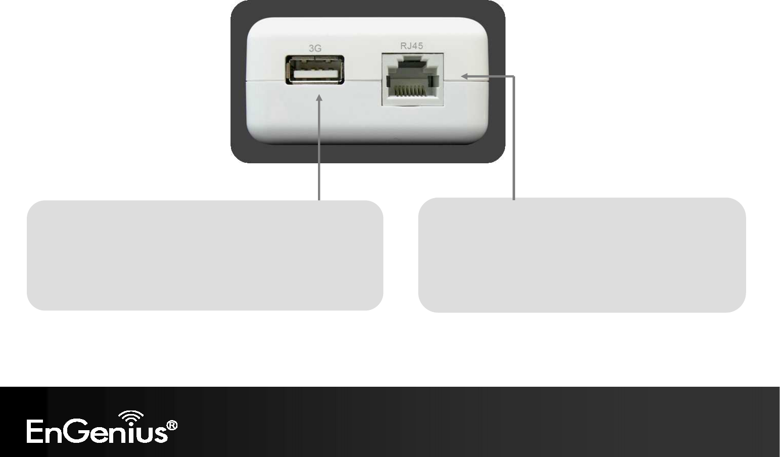
6. Hardware Overview
RJ45
This RJ45 port can be configured as WAN or LAN modes.
WAN: Connect to the Internet using DSL/Cable modem.
LAN: Connect to a computer, switch or hub.
3G USB
Attach a 3G USB adapter to share your 3G Internet connection.
When 3G USB adapter is connected, RJ45 automatically is set to LAN mode.
9
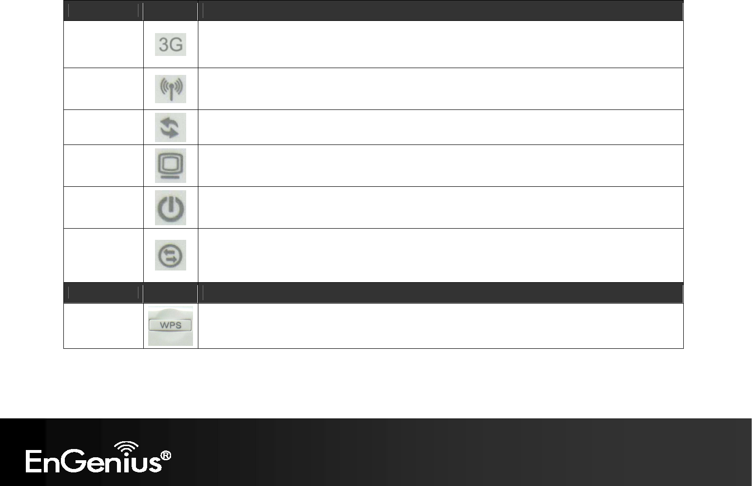
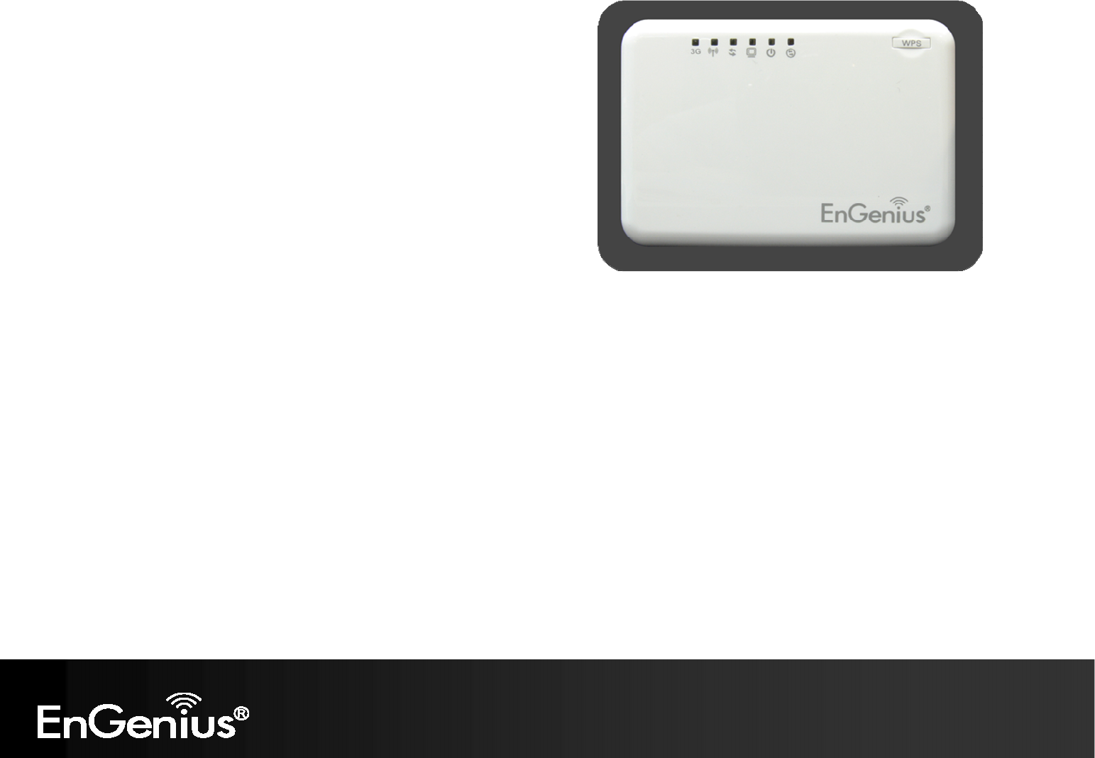
LED Lights icon Description
Mobile 3G
Color – Blue
Lights when 3G USB adapter is connected.
Blinks when 3G data transfer.
Wireless LAN
Color – Blue
Lights when Wireless signal is activated.
Blinks when Wireless data transfer.
WPS
Color – Blue
Blinks when WPS handshake is initialized.
LAN
Color – Blue
Lights when wired network device is connected to RJ45 port.
Blinks when data transfer occurs on RJ45 port.
Power
Color – Blue
Lights when device is powered ON.
Blinks device is Reset.
Mode
Indicates which mode the TRAVEL ROUTER is set to.
Orange – AP Router
Blue – Access Point
Green – Client Bridge
Buttons icon Description
WPS
Press this button to initialize WPS process.
Hold this button for 10 seconds to Reset to Factory Defaults.
10
7. Before you Begin
This section will guide you through the installation process. Placement
of the TRAVEL ROUTER is very important to avoid poor signal
reception and performance. Avoid placing the device in enclosed spaces
such as a closet, cabinet or wardrobe.
6.1 Considerations for Wireless Installation
The operating distance of all wireless devices cannot be pre-determined
due to a number of unknown obstacles in the environment that the
device is deployed. These could be the number, thickness and location
of walls, ceilings or other objects that the wireless signals must pass
through. Here are some key guidelines to ensure that you have the optimal wireless range.
1. Keep the number of walls and ceilings between the EnGenius access point and other network devices to a minimum. Each wall or
ceiling can reduce the signal strength, the degradation depends on the building’s material.
2. Building materials makes a difference. A solid metal door or aluminum stubs may have a significant negative effect on range.
Locate your wireless devices carefully so the signal can pass through a drywall or open doorways. Materials such as glass, steel,
metal, concrete, water (fish tanks), mirrors, file cabinets and brick will also degrade your wireless signal.
3. Interferences can also come from your other electrical devices or appliances that generate RF noise. The most usual types are
microwaves, or cordless phones.

11
6.2 AP Router / AP / Client Bridge Modes
There are three main modes to select from which will influence the installation of the TRAVEL ROUTER. This section will help you
determine which mode works with your setup.
AP Router Mode
AP Router Mode allows you to share an Internet connection to multiple computers.
AP Mode
AP mode allows you to have a wired or wireless router.
Client Bridge Mode
Client Bridge Mode allows a wired network device to connect to your wireless network, or create a point-to-point bridge.
Change mode from the top right of the User Interface.
Please see Configuring the TRAVEL ROUTER for instructions to access the Web-Based User Interface.
12
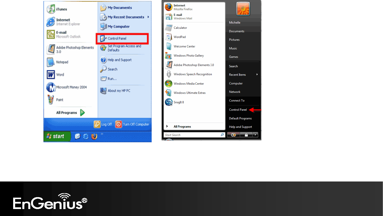
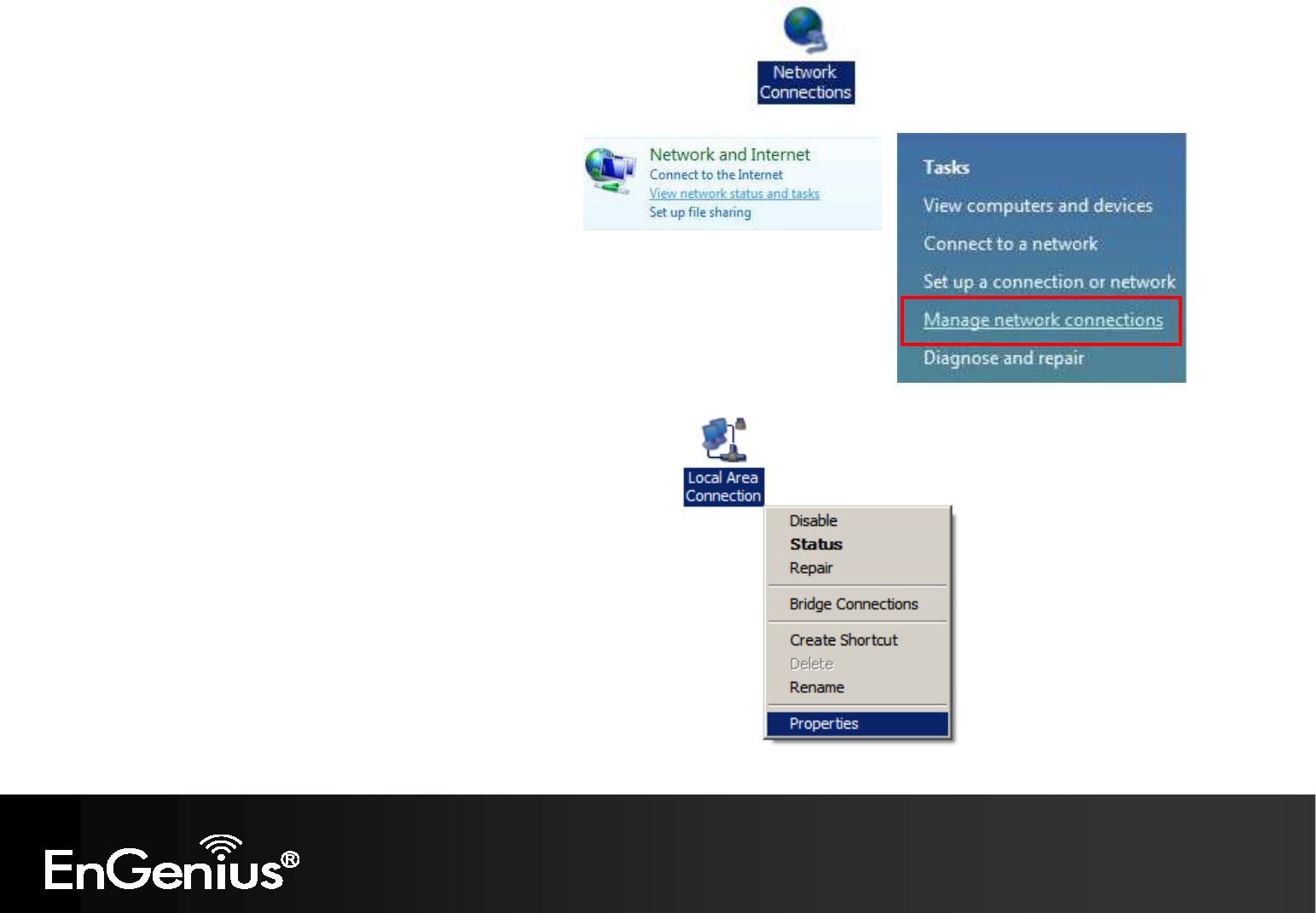
6.3 Check Network Settings (Windows XP/Vista)
1. Click Start button and open Control Panel.
Windows XP
Windows Vista
13
3.
Right click on [
Local Area C
onnection
]
and select [Properties].
Window
s Vista, click
[
View Network Status
and Tasks] then [Manage Network
Connections]
2.
Windows XP, click [
Network Connection]
14
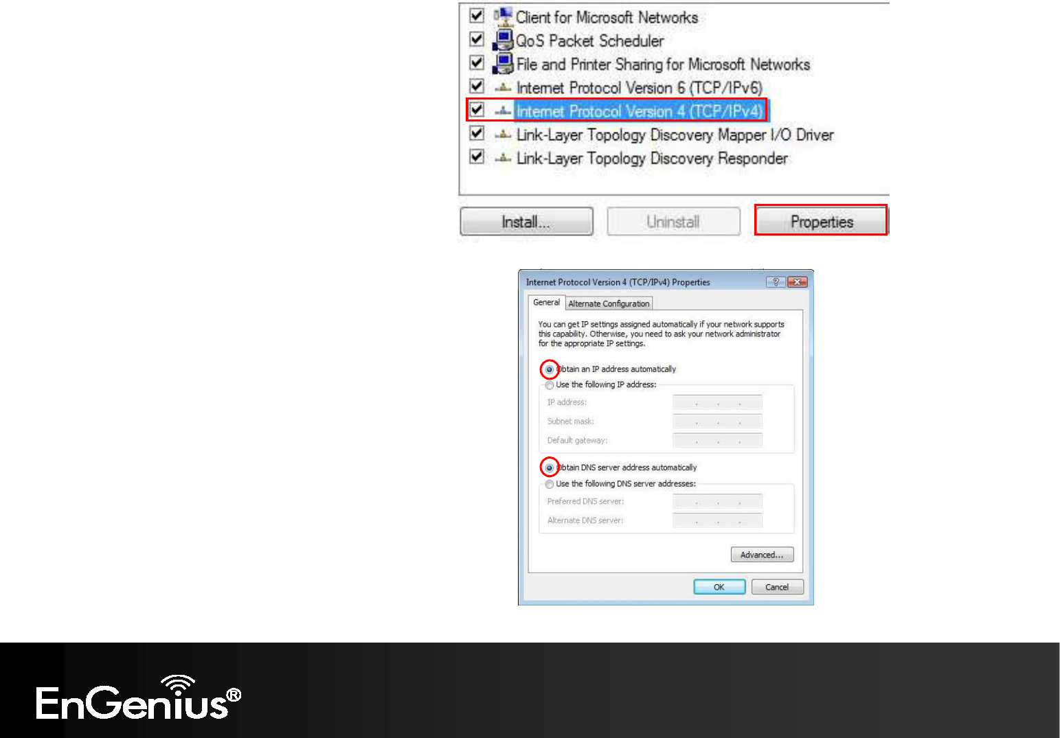
4.
Check
“Client for Microsoft Networks”, “File
and Printer Sharing”, and “Internet Protocol
(TCP/IP) is ticked. If not, please install them.
6.
Select
“Obtain an IP Address automatically”
and “Obtain DNS server address automatically”
and click [OK].
5.
Select
“Internet Protocol (TCP/IP)”
and
click [Properties]
15
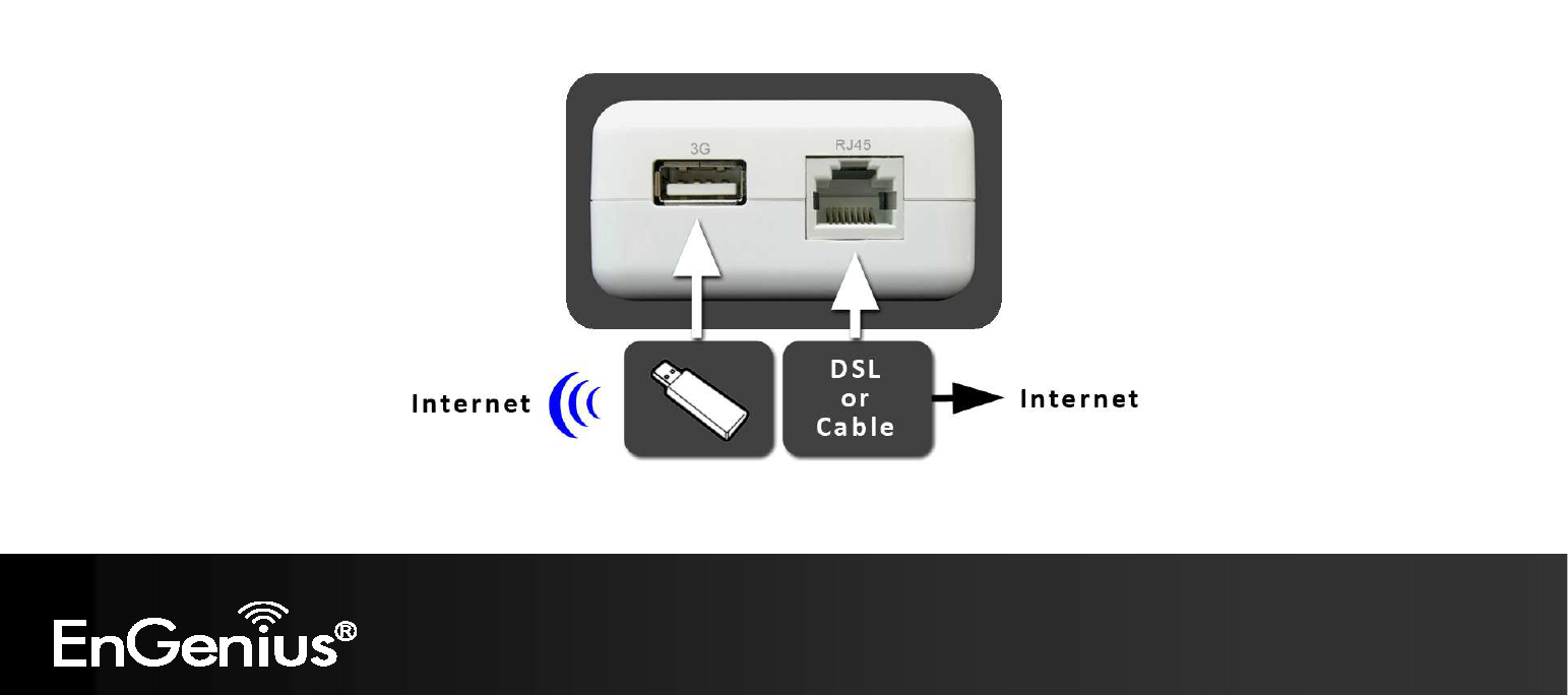
8. Hardware Installation
AP Router Mode:
One type of Internet connection is required. Please either connect the network cable from your DSL/Cable modem to the RJ45 port on
the TRAVEL ROUTER or connect a 3G adapter to the USB port.
Note: When 3G USB adapter is connected, RJ45 automatically is set to LAN mode.
AP Mode:
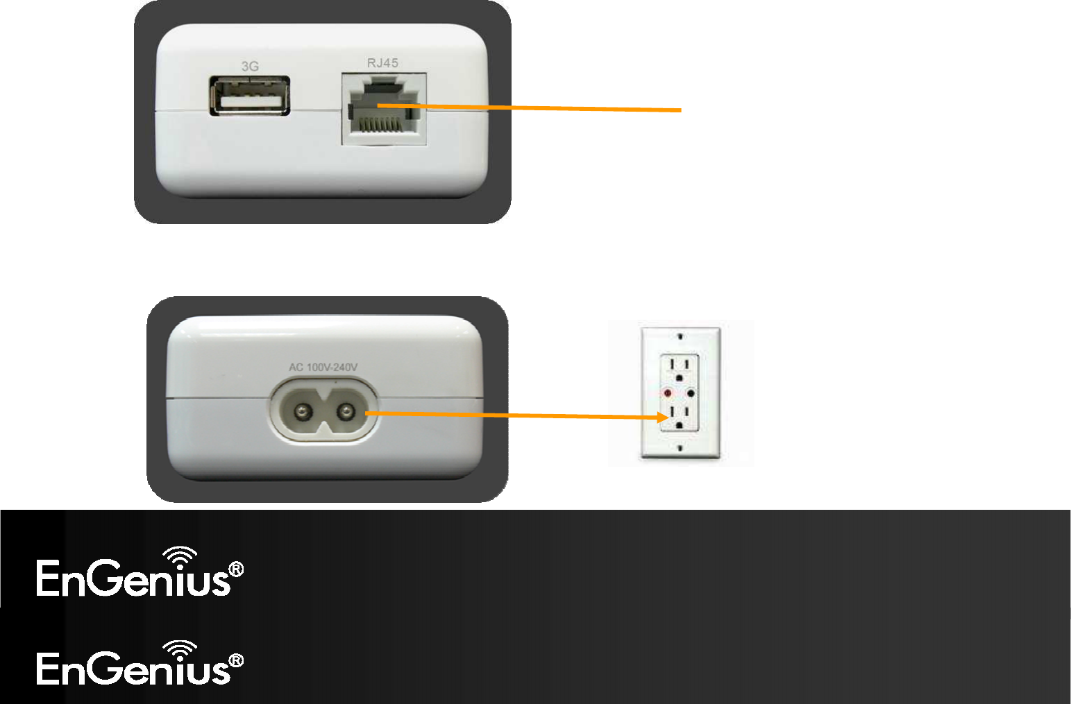
16
Connect the network cable to the RJ45 port.
Power On :
Use the AC Power cord to connect TRAVEL ROUTER and outlet or any other power supplies to provide the electricity to the device.
Wired Network

17
9. Configuring Travel Router
This section will show you how to configure the device using the web-based configuration interface.
Please use your wireless network adapter to connect the TRAVEL ROUTER.
Default Settings
IP Address 192.168.0.1
Username / Password admin / admin
Wireless Mode Enable
Wireless SSID EnGeniusxxxxxx
Wireless Security None
Note: xxxxxx mentioned in the wireless SSID above is the last 6 characters of your device MAC Address. This can be found on the device body label and is
unique for each device.
18
8.1 Setup Wizard
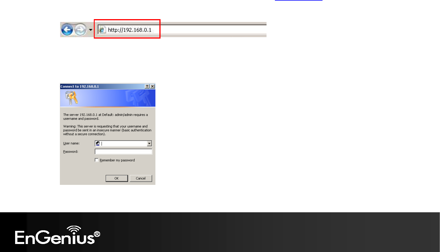
1. Open a web browser (Internet Explorer/Firefox/Safari) and enter the IP Address http://192.168.0.1
Note: If you have changed the default IP Address assigned to the TRAVEL ROUTER, ensure you enter the correct IP Address
.
2. The default username and password is admin. Once you have entered the correct username and password, click the OK button
to open the web-base configuration page.
19
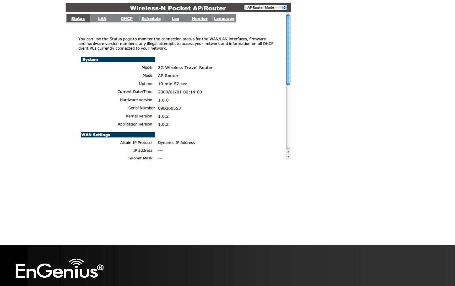
3. You will see the following screen if the log on process is successful.
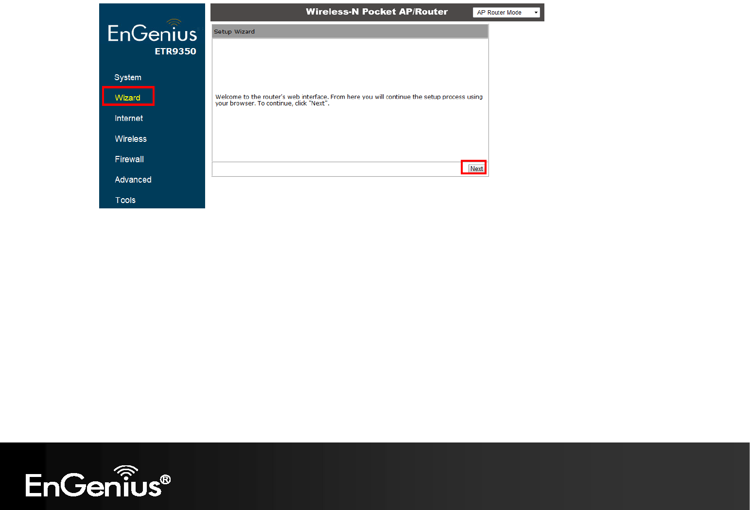
4. Click Wizard to enter the Setup Wizard.
Then click Next to begin the wizard.
20
21
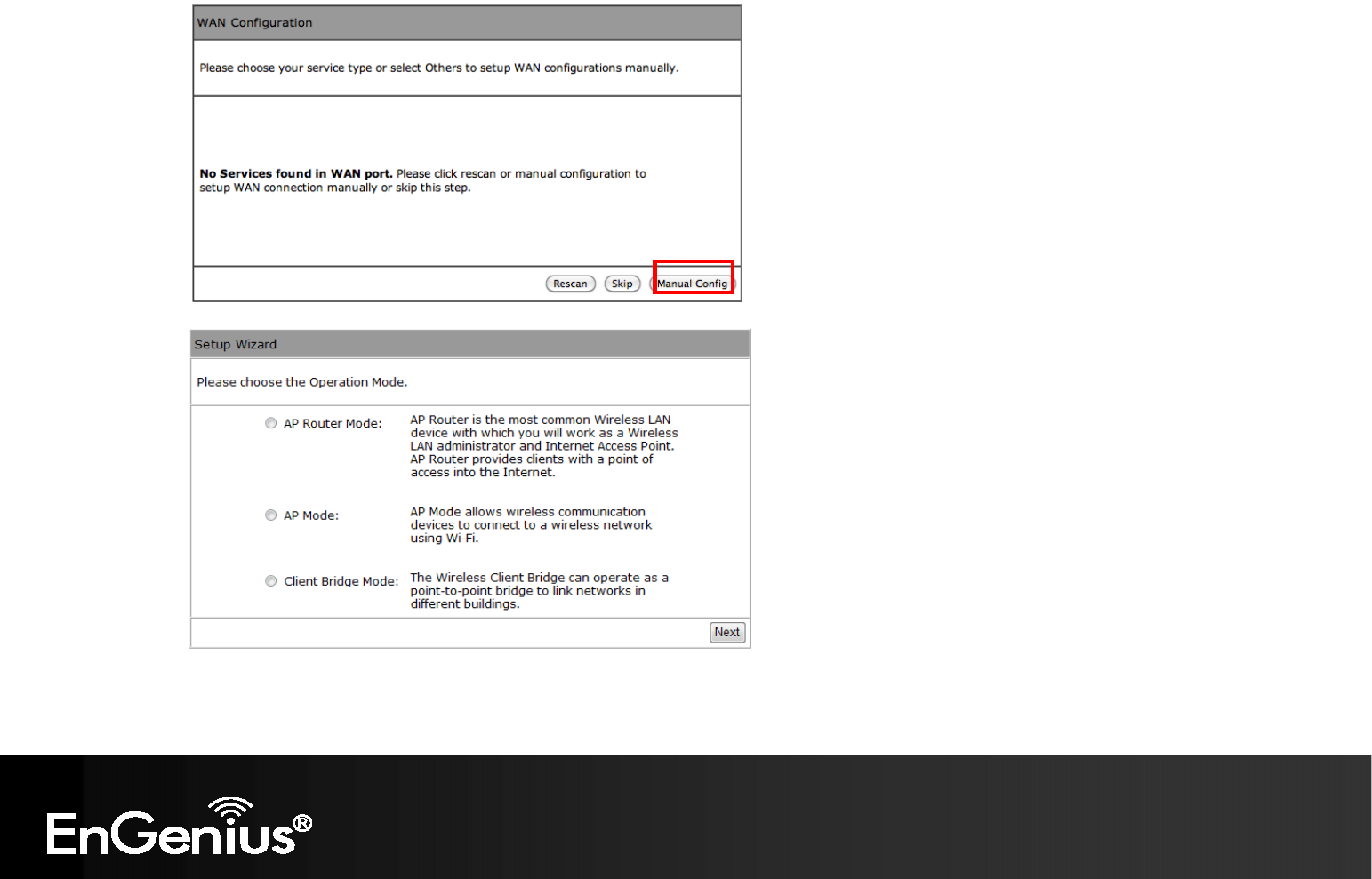
5. Select the Operation Mode.
Please ensure you have the proper cables connected as described in the Hardware Installation section.
22
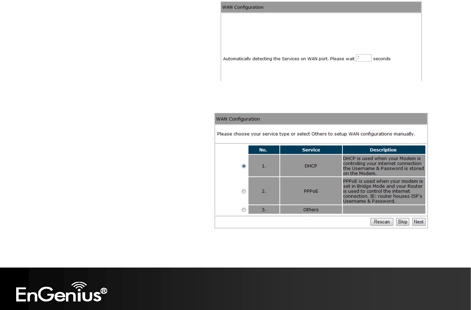
8.1.1 AP Router Mode
a) The device will now automatically search
for the correct Internet settings.
b) The most appropriate WAN type will be
determined and selected automatically.
If it is incorrect, please select Others
to set up the WAN settings manually.
23
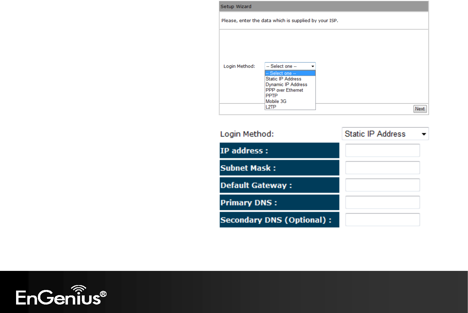
c) There are many WAN service types available.
Please obtain the correct settings from your
Internet Service Provider (ISP).
Static IP Address
If your ISP Provider has assigned you a fixed IP address,
enter the assigned IP address, Subnet mask, Default
Gateway IP address, and Primary DNS and Secondary
DNS (if available) of your ISP provider.
24
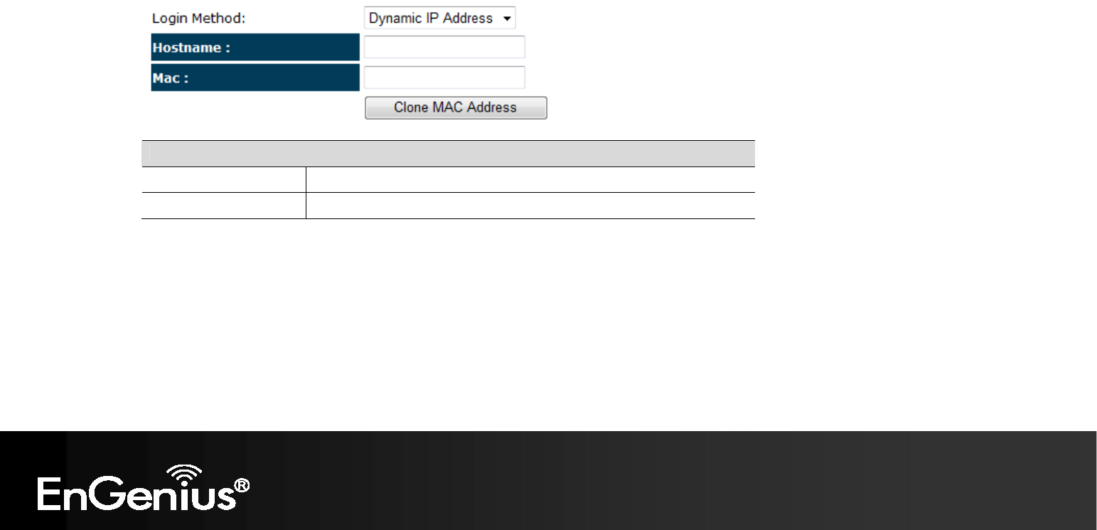
Dynamic IP Address
The IP Address is allocated automatically. However some ISP’s will also recognize the MAC address and will reject connections if the
MAC address does not match.
If your ISP has recorded the MAC address of your computer’s Ethernet LAN card, please connect only the computer with the authorized
MAC address, and click the Clone MAC Address button.
This will replace the AP Router MAC address to the computer MAC address. The correct MAC address is used to initiate the connection
to the ISP.
Dynamic IP Address
Hostname: This is optional. Only required if specified by ISP
MAC: The MAC Address that is used to connect to the ISP.
25
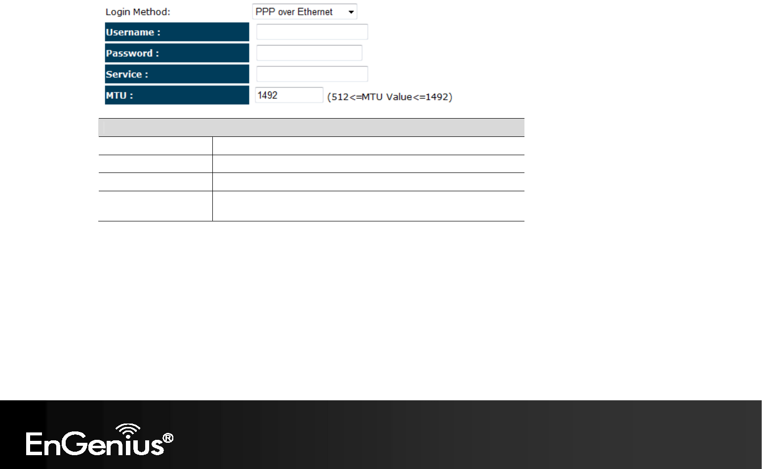
PPP over Ethernet
ISP requires an account username and password.
PPP over Ethernet
Username: Username assigned to you by the ISP
Password: Password for this username.
Service: You can assign a name for this service. (Optional)
MTU: The maximum size of packets.
Do not change unless mentioned by the ISP.
26
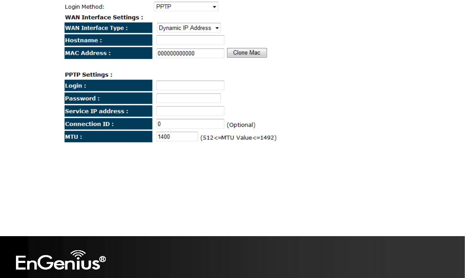
Point-to-Point Tunneling Protocol (PPTP)

27
PPTP WAN Interface Settings
WAN Interface Type: Select whether the ISP is set to Static IP or Dynamic IP addresses.
Hostname: This is optional. Only required if specified by ISP
MAC: The MAC Address that is used to connect to the ISP.
PPTP Settings
Login: Username assigned to you by the ISP
Password: Password for this username.
Service IP Address: The IP Address of the PPTP server.
Connection ID: This is optional. Only required if specified by ISP
MTU: The maximum size of packets.
Do not change unless mentioned by the ISP.
28
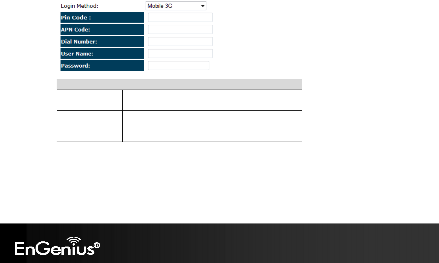
Mobile 3G
Please ensure your 3G USB card is connected to the TRAVEL ROUTER and has an active USIM card inserted.
Mobile 3G
Pin Code: Enter the Pin code for your USIM card if required.
APN Code: Enter the APN code for the network provider
Dial Number: Only required if specified by ISP
User Name: Account Username. Only required if specified by ISP
Password: Account Password. Only required if specified by ISP
29
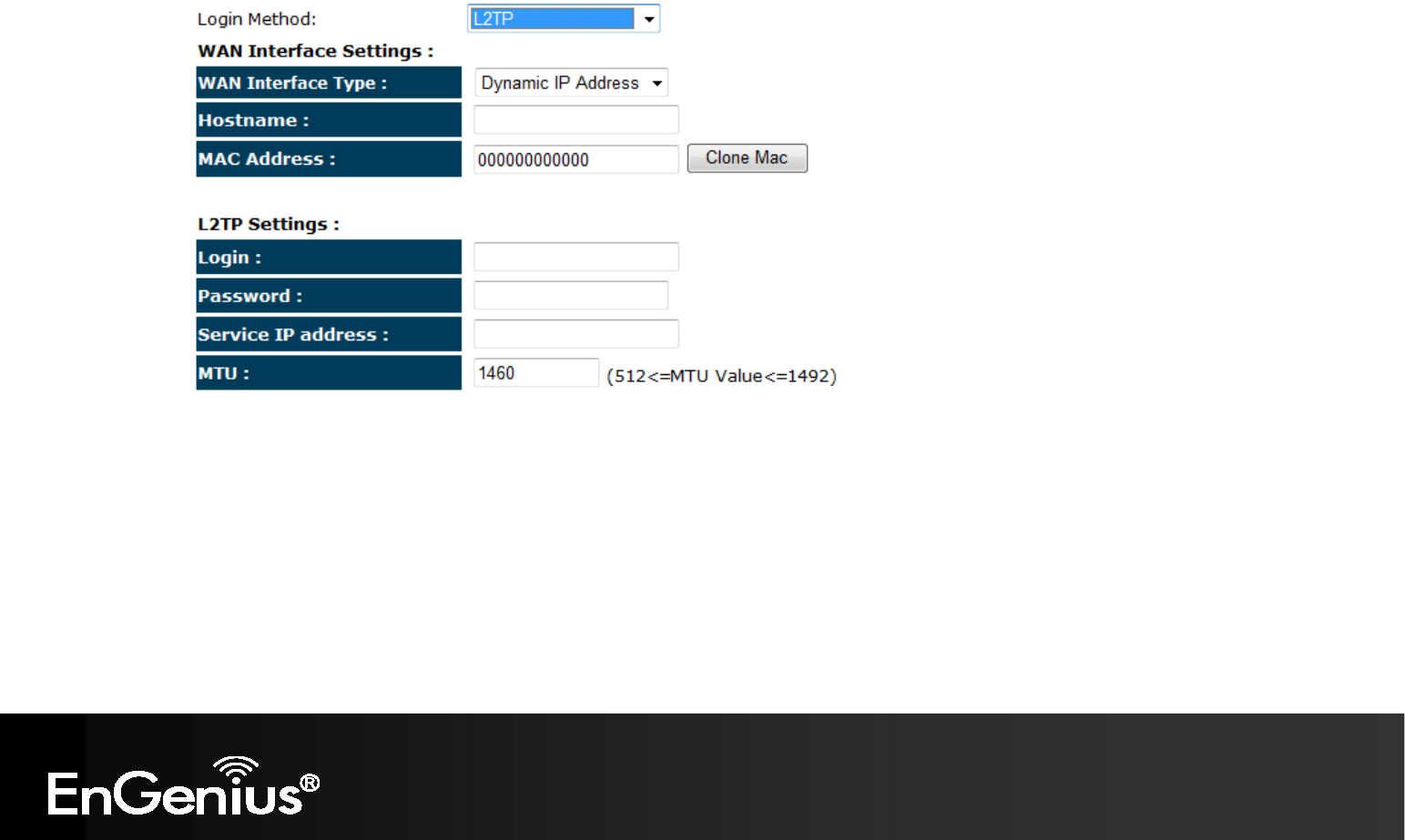
Layer-2 Tunneling Protocol (L2TP)

30
L2TP WAN Interface Settings
WAN Interface Type: Select whether the ISP is set to Static IP or Dynamic IP addresses.
Hostname: This is optional. Only required if specified by ISP
MAC: The MAC Address that is used to connect to the ISP.
L2TP Settings
Login: Username assigned to you by the ISP
Password: Password for this username.
Service IP Address: The IP Address of the PPTP server.
MTU: The maximum size of packets.
Do not change unless mentioned by the ISP.
31
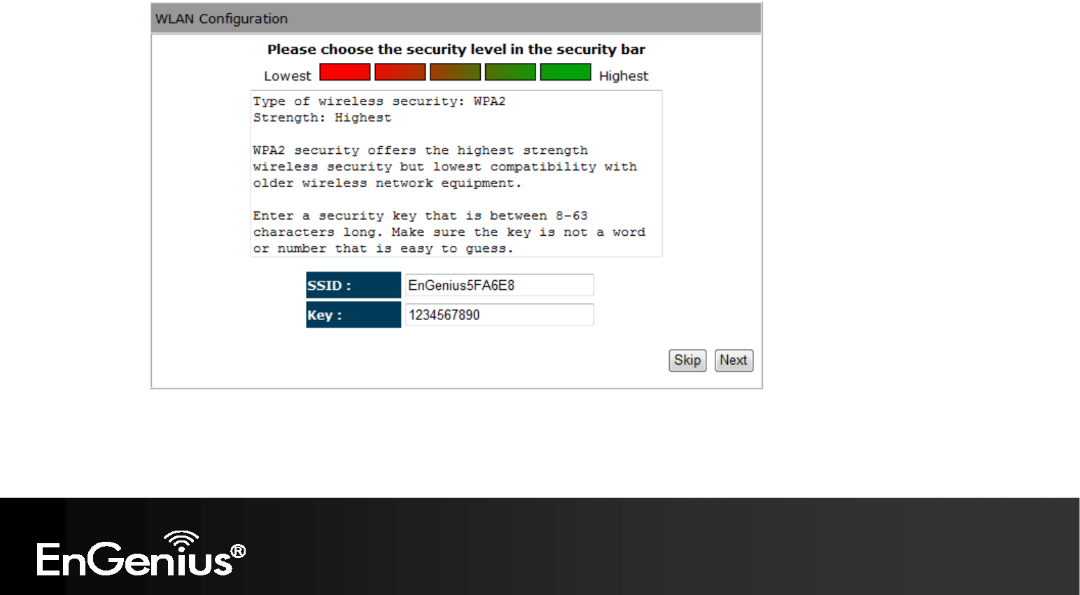
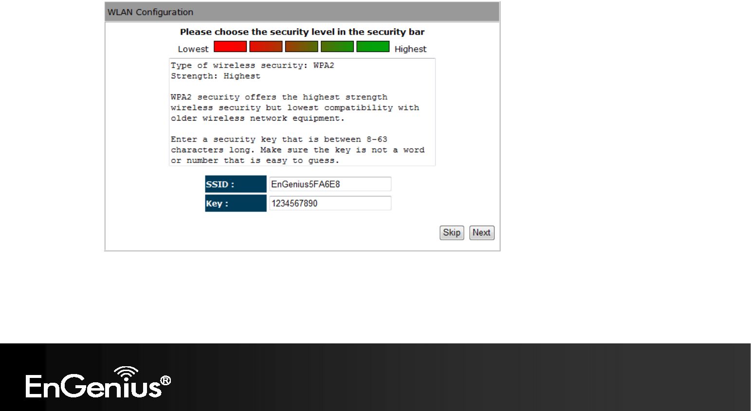
d) Setup the level of wireless security to be used.
EnGenius recommends the Highest level of security to be used.
Note: 802.11n wireless speeds may not be achievable if the security is setup to Lowest and Low level.
SSID: Enter the name of your wireless network.
Key: Enter the security key for your wireless network.
32
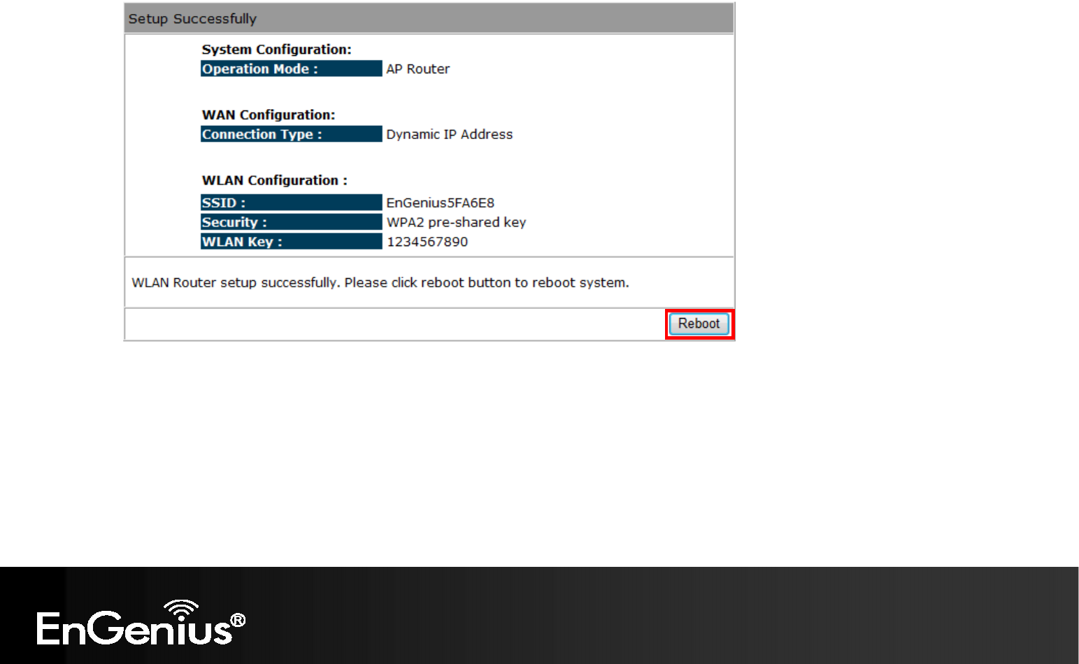
e) Check the settings are correct, and then click Reboot to apply the settings.
33
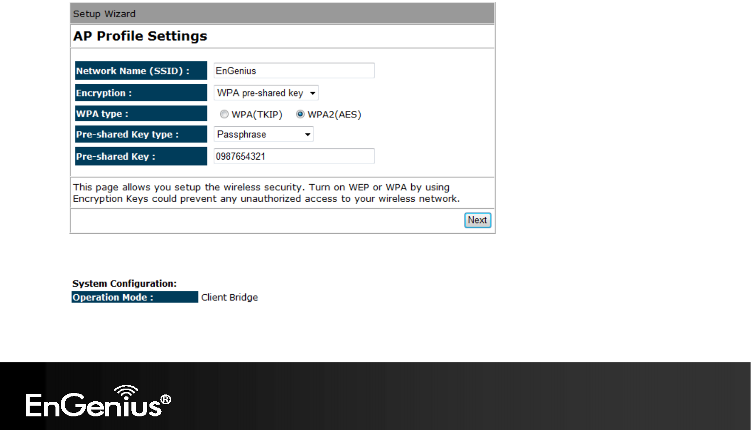
8.1.2 AP Mode
a) Select the level of wireless security to be used.
EnGenius recommends the Highest level of security to be used.
Note: 802.11n wireless speeds may not be achievable if the security is setup to Lowest and Low level.
SSID: Enter the name of your wireless network.
Key: Enter the security key for your wireless network.

34
b) Check the settings are correct, and then click Reboot to apply the settings.
35
8.1.3 Client Bridge Mode
a) In this mode, the TRAVEL ROUTER will connect to a wireless network as a client device.
Please enter the SSID and security settings of that wireless network.
b) Check the settings are correct, and then click Reboot to apply the settings.
36
8.2 Web-Based Configuration
8.2.1 System
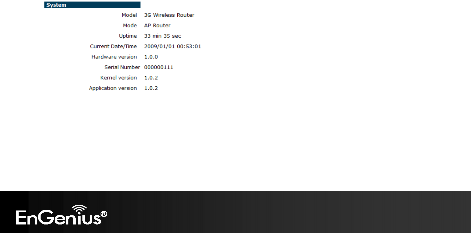
Status
This page allows you to monitor the status of the device.

37
Status
Model: Description of this device.
Mode: The device is currently in which mode.
Uptime: The duration about the device has been operating without powering down
or reboot.
Current Date/Time: The device’s system time.
If this is incorrect, please set the time in the Tools / Time page.
Hardware version and
Serial Number: Hardware information for this device.
Kernel and Application
version: Firmware information for this device.
38
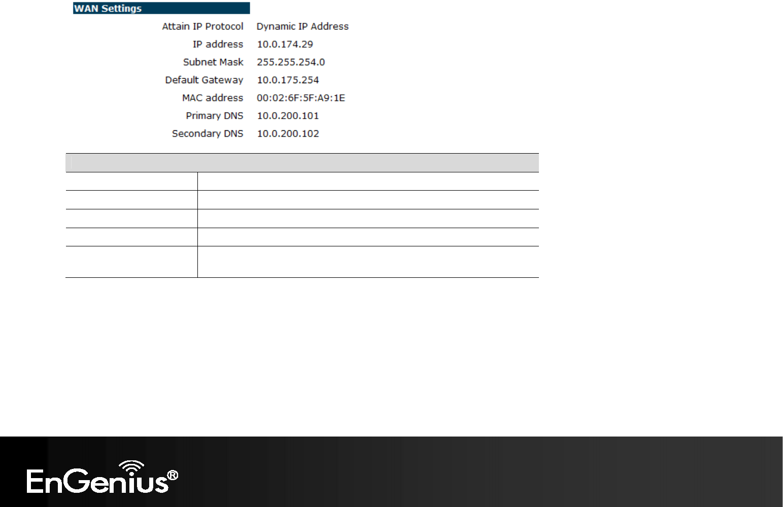
WAN Settings
Attain IP Protocol: Method used to connect to the Internet
IP address: The WAN IP Address of the device.
Subnet Mask The WAN Subnet Mask of the device.
MAC address The MAC address of the device’s WAN Interface.
Primary and Secondary
DNS: Primary and Secondary DNS servers assigned to the WAN connection.
39
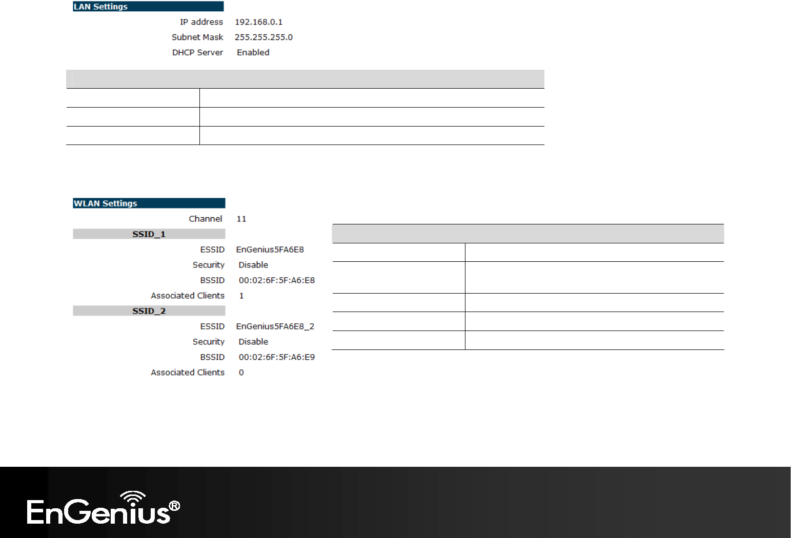
LAN Settings
IP address: The LAN IP Address of the device.
Subnet Mask The LAN Subnet Mask of the device.
DHCP Server Whether the DHCP server is Enabled or Disabled.
WLAN Settings
Channel: The wireless channel in use.
ESSID: The SSID (Network Name) of the wireless network.
(up to 4 SSID’s are supported)
Security: Wireless encryption is enabled for this SSID.
BSSID: The MAC address of this SSID.
Associated Clients: The number of wireless clients connected to this SSID.