Sensys Networks FLEXRAD FLEXRADIO CABINET User Manual APCC Installation Guide
Sensys Networks, Inc. FLEXRADIO CABINET APCC Installation Guide
Contents
- 1. Installation Guide - Access Point Controller Card
- 2. Quick Start Guide
Installation Guide - Access Point Controller Card
APCC
Sensys Networks VDS240 Wireless Vehicle
Detection System
Access Point Controller Card (APCC) Installation Guide
P/N 152-240-030-005, Rev F
June 2015
Document Properties
This document is reference material for the Sensys Networks VDS240 wireless vehicle
detection system from Sensys Networks, Inc.
P/N 152-240-030-005 Rev F
Sensys Networks, Inc. makes no representation or warranties with respect to the
contents hereof and specifically disclaims any implied warranties of merchantability or
fitness for any particular purpose. Furthermore, Sensys Networks reserves the right to
revise this publication and to make changes from time to time in the content hereof
without obligation of Sensys Networks to notify any person or organization of such
revisions or changes.
© 2007 - 2015 – All rights reserved.
Sensys Networks and the Sensys Networks logo are trademarks of Sensys Networks,
Inc. All other products, names and services are trademarks or registered trademarks of
their respective owners.
Regulatory Statements
FCC Compliance Statement
This device complies with part 15 of the FCC rules. Operation is subject to the following
two conditions:
(1) This device may not cause harmful interference.
(2) This device must accept any interference received, including interference that
may cause undesired operation.
Any changes or modifications to this product not authorized by Sensys Networks could
void the EMC compliance and negate the authority to operate the product.
RF Exposure Statement
This device has been tested and meets the FCC RF exposure guidelines. It should be
installed and operated with a minimum distance of 20 cm between the radiator of RF
energy and the body of users, operators, or others.
Improper use or tampering with the device is prohibited and may not ensure
compliance with FCC exposure guidelines.
Warnings
No Safety Switching
Sensys Networks does not allow its equipment to be used for safety applications such
as controlling a mechanical gate or switching a train to avoid a collision.

Lithium Thionyl Chloride Batteries
Sensys Networks uses Lithium Thionyl Chloride batteries in the following products:
Sensors (VSN240-F, VSN240-T, VSN240-S, VSN240-M, VSN240-F-2,
VSN240-T-2)
Repeaters (RP240-BH-2, RP240-BH-LL-2, FLEX-RP-B-2, FLEX-RP-B-LL-2)
Lithium batteries are widely used in electronic products because they contain more
energy per unit -weight than conventional batteries. However, the same properties that
deliver high energy density also contribute to potential hazards if the batteries are
damaged. Improper use or handling of the batteries may result in leakage or release of
battery contents, explosion, or fire.
Following are the recommendations of the battery manufacturer for proper use and
handling of batteries in the Sensys Networks devices mentioned above:
DO NOT charge or attempt to recharge the batteries (they are NOT
rechargeable)
DO NOT crush or puncture batteries
DO NOT short-circuit the batteries
DO NOT force over-discharge of the batteries
DO NOT incinerate or expose batteries to excessive heating
DO NOT expose battery contents to water
DO dispose of batteries and devices containing batteries in accordance with
local regulations
N
OTE
:
Sensys Networks wireless sensors contain no serviceable parts and should never be
disassembled. Installation and removal of sensors from pavement should only be done by
trained personnel and care should be taken to insure that the sensor casing is not punctured
or crushed.
Additional safety information is available from the battery's manufacturer:
Sensor and repeater battery cell: http://www.ewtbattery.com/en/
DownView.asp?ID=9
Document Control
Sensys Networks continually reviews and revises its technical publications Please
address questions, suggestions, or corrections to support@sensysnetworks.com.
Sensys Networks Technical Publications
For additional information regarding Sensys Networks products and applications,
design guides, configuration guides, and best practices, refer to the Sensys Networks
technical documents library available at http://sensysnetworks.com/
resources?tech_docs.
Contact Information
Sensys Networks, Inc.
1608 Fourth Street, Suite 200
Berkeley, CA 94710 USA
+1 (510) 548-4620
www.sensysnetworks.com

Sensys Networks, Inc. Access Point Controller Card (APCC) v
Installation Guide
Contents
Chapter 1: Introduction ............................................................................................... 1
What's Inside ..................................................................................................................................1
Chapter 2: Overview ................................................................................................... 3
Access Point Controller Card (APCC) ........................................................................................3
Contact Closure Expansion Card .........................................................................................3
Types of APCC Configurations ....................................................................................................4
APCC System ..........................................................................................................................4
APCC Serial Port Protocol (SPP) Digital Radio ..............................................................5
Isolator ...............................................................................................................................5
APCC Package Contents ............................................................................................................5
SPP Package Contents .................................................................................................................6
Universal Mounting Kit Contents ...........................................................................................7
Additional Parts and Equipment Required ................................................................................8
Chapter 3: APCC Installation Considerations ........................................................... 9
Identifying the SPP and Sensors ...................................................................................................9
SPP ............................................................................................................................................9
Wireless Sensors .....................................................................................................................10
Determining the Device Configuration ....................................................................................10
Configuration Worksheet .....................................................................................................10
Determining Slots and Contact Closures .................................................................................11
Mapping Wireless Sensors to Contact Closures .......................................................................12
Chapter 4: SPP Installation Considerations .............................................................. 13
Powering the SPP ........................................................................................................................13
Acquiring Power From a Traffic Controller .........................................................................13
Acquiring Power From Traffic Controller Using an Isolator ...............................................14
Voltages .................................................................................................................................15
Cabling ..................................................................................................................................15
Collecting Data From the APCC ...............................................................................................15
Determining the Location of the SPP ........................................................................................15
Optimal Location Criteria ....................................................................................................15
Chapter 5: APCC Installation Procedures ................................................................ 17
Overview ......................................................................................................................................17
Determining the Card ID and Setting it via Circuit-board Dip Switches SW1 and SW2 ......17
Factory Default Card ID .......................................................................................................18
Querying the Backplane for an Assigned Address ...........................................................18
Setting the Slot-Number With Circuit-board Dip Switch SW2 ...........................................19

vi Access Point Controller Card (APCC)
Installation Guide Sensys Networks, Inc.
Exception ........................................................................................................................19
Setting the Shelf-Number With Circuit-board Dip Switch SW1 ........................................19
Determining the Controller Type and Setting it via Circuit-board Dip Switch SW1 .............19
Connecting the Cables to Each Device .................................................................................20
Cabling Summary .......................................................................................................................21
Chapter 6: SPP Installation Procedures .................................................................... 23
Tools Required for SPP Installation .............................................................................................23
Step-by-Step Procedures ...........................................................................................................24
Installing the Mounting Plate on Poles ...............................................................................24
Installing the Mounting Plate on Walls ...............................................................................25
Installing the Mounting Plate on Beams .............................................................................25
Determining the Type of SPP Radio Bulkhead Connector ..............................................26
SPP Radio Bulkhead Connector ...................................................................................26
Connecting the Cable to an SPP Radio with the Hex-head Connector .......................26
Components ...................................................................................................................26
Step-by-Step Procedures .....................................................................................................27
Proper Fit (little to no gap between edges of cut) ....................................................30
Improper Fit (gap between edges of cut) ..................................................................30
Proper Fit (bushing fully seated into guides) ...............................................................31
Improper Fit (bushing poorly seated into guides) ......................................................32
Proper Fit (recessed bushing, smooth face) ...............................................................33
Improper Fit (bushing not recessed, pinched edge, mushroomed face) ..............33
Removing the Cable Connection ......................................................................................33
Chapter 7: Configuration .......................................................................................... 35
Overview ......................................................................................................................................35
Configuration Methods ........................................................................................................36
Configuring Channels With the Front-Panel Interface ............................................................36
General Procedure ..............................................................................................................36
Saving the Configuration ..............................................................................................37
Enabling / Disabling a Channel ..........................................................................................37
Specifying the Channel Mode ............................................................................................38
Setting a Presence Mode Modifier (Optional) ..................................................................38
Using Delay and Extension ............................................................................................38
Specifying the Type of Communication Used by the Channel Status Monitor ............39
Starting TrafficDOT and Connecting to an APCC ...................................................................40
Configuring Channels with TrafficDOT ......................................................................................42
Entering controller card information ..................................................................................42
Configuring Channel State .................................................................................................43
Configuring Channel Mode ................................................................................................43
Configuring Presence Mode Modifier ................................................................................44
Configuring Channel Holdover Duration ...........................................................................44
Defining Sensor-to-Channel Mappings ....................................................................................44
Exiting TrafficDOT .........................................................................................................................45
Appendix A: X Mode LED Displays for Slot Numbers .............................................. 47
Examples ......................................................................................................................................48

Sensys Networks, Inc. Access Point Controller Card (APCC) vii
Installation Guide
Appendix B: Circuit-board Dip Switch SW1 Settings ............................................... 49
Settings for Shelf Number ...........................................................................................................49
Settings for TS1 and TS2 Controllers ...........................................................................................50
Appendix C: Circuit-board Dip Switch SW2 Settings .............................................. 51
Settings for Slot Number .............................................................................................................51
Appendix D: Pre-Installation Worksheets ................................................................ 53
Appendix E: Contact Closure Card External Interfaces ......................................... 55
Backplane Edge Connections ..................................................................................................56
IN RJ45 Connector Pin Assignments ..........................................................................................58
OUT RJ45 Connector Pin Assignments ......................................................................................58

viii Access Point Controller Card (APCC)
Installation Guide Sensys Networks, Inc.

Access Point Controller Card (APCC) 1
Sensys Networks, Inc. Installation Guide
Chapter 1
Introduction
This guide provides information and procedures for installing Sensys Networks
Access Point Controller Card (APCC) and the APCC Serial Port Protocol (SPP)
digital radio in conjunction with the Sensys Networks VDS240 wireless vehicle
detection system. This document is intended to be used by Sensys Networks
customers, consultants, partners, dealers, and those who are interested in the
application of wireless communication technology to the challenges of traffic
detection, management, and control.
What's Inside
This guide includes the following information:
Chapter 1: Introduction, defines the purpose and scope of the guide.
Chapter 2: Overview, provides an overview of the APCC and its additional
components. It also describes the contents of a product shipment.
Chapter 3: APCC Installation Considerations, provides the installation
considerations for the APCC.
Chapter 4: SPP Installation Considerations, provides the installation considerations
for the SPP.
Chapter 5: APCC Installation Procedures, provides instructions for installing and
cabling the APCC.
Chapter 6: SPP Installation Procedures, provides instructions for installing and
mounting the SPP.
Chapter 7: Configuration, provides instructions for configuring an APCC and
expansion cards.
Appendix A: X Mode LED Displays for Slot Numbers, depicts the channel LED
displays when an APCC operates in X mode.

Chapter 1
2 Access Point Controller Card (APCC)
Installation Guide Sensys Networks, Inc.
Appendix B: Circuit-board Dip Switch SW1 Settings, depicts SW1 settings that
identify the shelf number portion of the unique card address.
Appendix C: Circuit-board Dip Switch SW2 Settings, depicts combinations of switch
settings on the circuit-board dip switch SW2.
Appendix D: Pre-Installation Worksheets, provides worksheets for capturing
pre-installation information.
Appendix E: Contact Closure Card External Interfaces, provides the connector pin
assignments for the external interfaces of contact closure master and
expansion cards.

Access Point Controller Card (APCC) 3
Sensys Networks, Inc. Installation Guide
Chapter 2
Overview
This chapter provides an overview of the APCC and its additional components.
The chapter also describes the contents of a product shipment.
Access Point Controller Card (APCC)
The Sensys Networks VDS240 Wireless Vehicle Detection System detects the
presence and movement of vehicles with magneto-resistive sensors mounted in
the pavement. Wireless sensors continuously transmit detection data to the APCC
that collects and forwards data to remote traffic management systems or local
traffic signal controllers such as the CalTrans Type 170, Type 2070 ATC and
NEMA TS-1, and TS-2 controllers.
The Sensys Networks Access Point Controller Card (APCC), is a second generation
controller card that maintains low power consumption, supports multiple radios,
and allows for additional communication and processing power. The APCC, which
is compatible with all of Sensys Networks VDS240 Wireless Vehicle Detection
System products, receives and processes data from the sensors. The APCC then
relays the sensor detection data to a roadside traffic controller or remote server
traffic management system.
Contact Closure Expansion Card
Additional capacity (to handle more sensors or controller channels) is provided by
a contact closure expansion card (EX card). EX cards use the same form factor as
APCC cards and are daisy-chained to a CC interface on the APCC on the front-
panel RJ45 jacks or backplane connectors. Up to 63 EX cards can be used per
APCC card.
Chapter 2
4 Access Point Controller Card (APCC)
Installation Guide Sensys Networks, Inc.
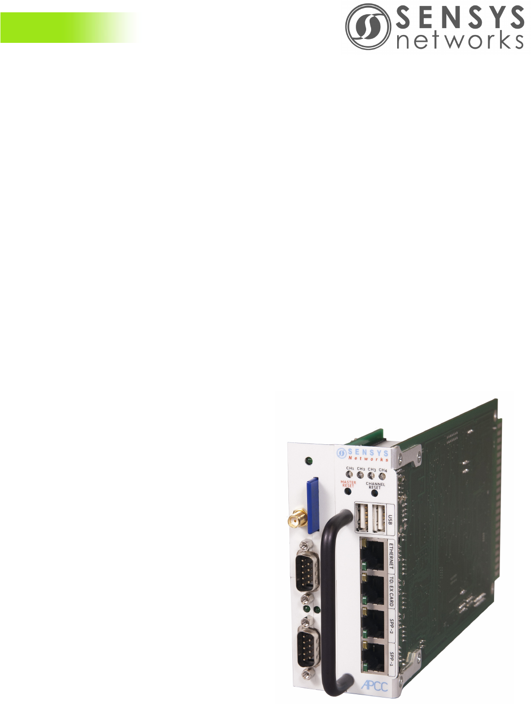
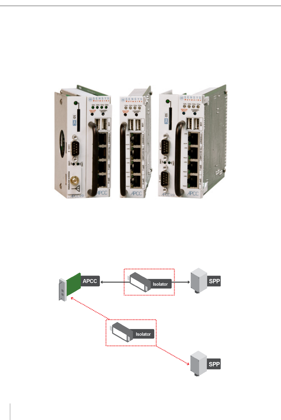
Types of APCC Configurations
The APCC single-slot configuration consists of dual APCC radio ports, Sensys
Networks Expansion (EX) port, and contact closure interface via backplane to a
traffic controller. It also has dual USB 2.0 full speed host ports and 10/100Base-T
network access. The APCC dual-slot configuration adds an SD memory card, real-
time battery-backed clock, dual serial (DB9) interface, or an optional built in
cellular modem.
Figure 2.1. APCC configurations
APCC System
The minimum APCC system consists of an APCC and one SPP radio. The system
can also consist of multiple SPP radios and an isolator that offers electrical
isolation up to 1500V, surge protection up to 1500V, and AC power cross
protection.
Figure 2.2. APPC system configuration
Overview
Access Point Controller Card (APCC) 5
Sensys Networks, Inc. Installation Guide
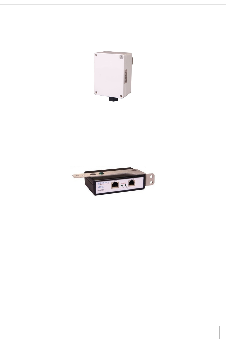
APCC Serial Port Protocol (SPP) Digital Radio
The APCC, along with the SPP, maintains two-way wireless links to an
installation’s sensors and repeaters, establishes overall time synchronization, and
transmits configuration commands and message acknowledgements.
Figure 2.3. SPP digital radio
Isolator
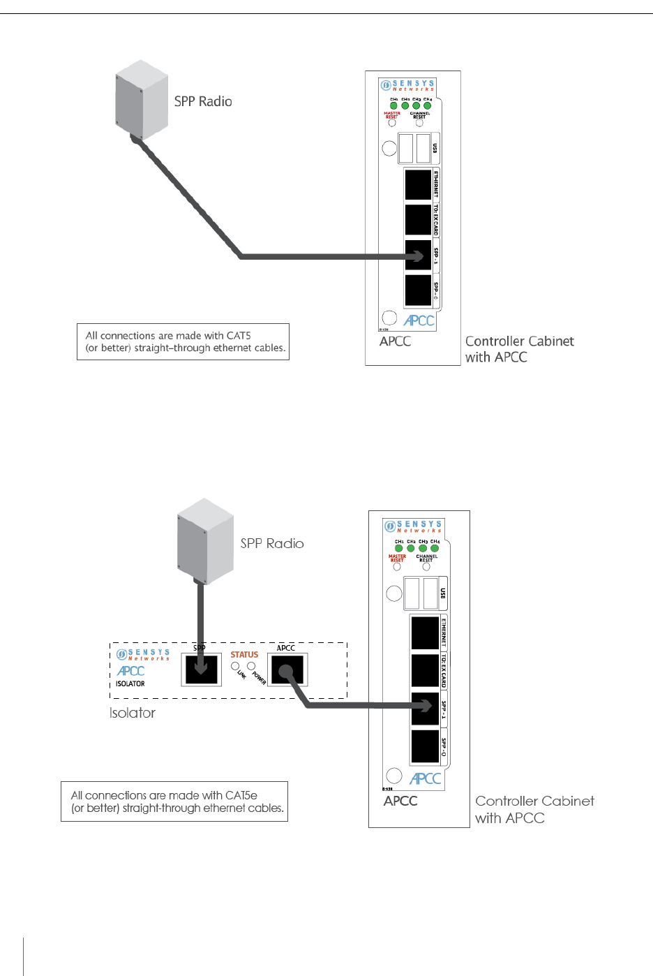
The isolator is an optional component that provides the following services:
connects an SPP to the APCC
isolates and routes power from the controller backplane to the SPP
extends the communication for the APCC to and from the SPP at RS422
distance.
Figure 2.4. Isolator
APCC Package Contents
Each APCC is shipped with the items listed below. Verify that you have received all
of them. In the event that some items are missing, contact Sensys Networks or the
party that supplied the equipment to you.
The items in a Sensys Networks APCC shipment include:
An APCC
Access Point Controller Card Installation Guide (this document)
Information sheet
The Sensys Networks APCC is shipped with a factory default configuration suitable
for bench-testing the device and typically require further configuration to meet the
needs of specific applications. Hardware serial numbers are found on the
information sheet.
The APCC and EX cards are available in the models as shown below. Verify that
you have the correct model for your application.

Chapter 2
6 Access Point Controller Card (APCC)
Installation Guide Sensys Networks, Inc.
Table 1. APCC models
SPP Package Contents
Each SPP is shipped with the items listed below. Verify that you have received all
of them. In the event that some items are missing, contact Sensys Networks or the
party that supplied the equipment to you.
The items in an SPP shipment include:
An SPP
“Tool less” push/pull Ethernet bulkhead connector
Information sheet (one per device)
Item that is shipped separately:
Universal mounting kit (kit can be purchased from Sensys Networks)
SPP digital radios are shipped with a factory default configuration suitable for
bench-testing the device and applicable to many field environments. The
information sheet details the physical attributes of the SPP as well as key
configuration elements.
SPP information sheets contain the following elements:
Serial number – a globally unique identifier for the SPP
Default RF channel – a critical configuration property
Default IP address
Firmware release version
N
OTE
:
RF channel is essential for communicating and further configuring the wireless sensor
network. Save all information sheets for the party who will configure and use the network
after it is installed. Refer to the Configuration chapter of the Sensys Networks VDS240
Wireless Vehicle Detection System Reference Guide for more information about network
operations and configuration.
Product Description
APCC-M APCC Module
APCC-M-E APCC Module with Enhanced Ethernet
APCC-MP-E APCC Module with Peripheral Support and Enhanced Ethernet
APCC-MP-EG APCC Module with Peripheral Support and Enhanced Ethernet, GSM
APCC -MP-EV APCC with Peripheral Support and Enhanced Ethernet, Verizon
EX240 Expansion Card for Type 170, Type 2070, or NEMA TS1 or
TS2 traffic controllers
Overview
Access Point Controller Card (APCC) 7
Sensys Networks, Inc. Installation Guide
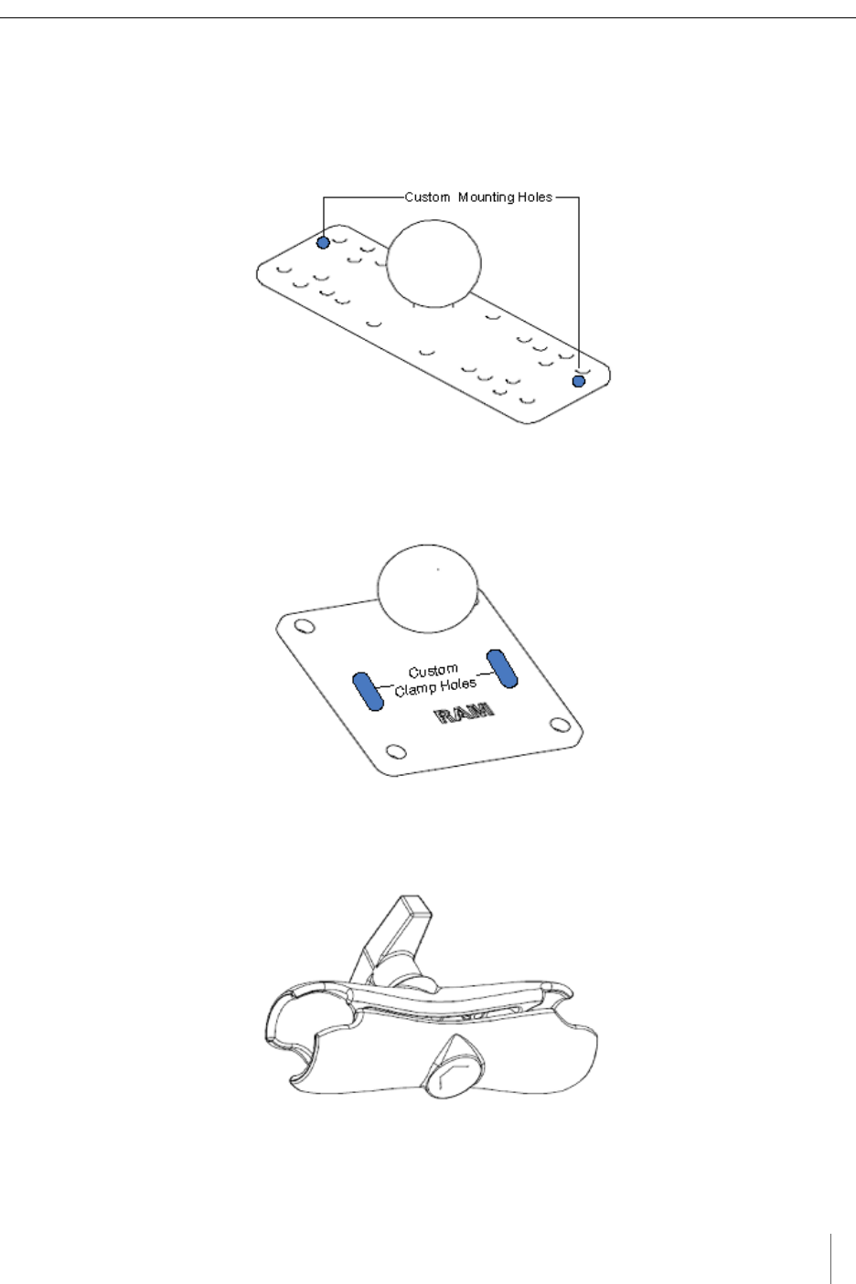
Universal Mounting Kit Contents
The following parts are included in the SPP mounting kit:
SPP ball plate (rectangular, attached to the SPP at the factory, refer to Figure
2.5)
Figure 2.5. Factory installed ball plate (rectangular)
Surface mounting ball plate (square, refer to Figure 2.6)
Figure 2.6. Surface (wall/beam/pole) mounting ball plate (square)
Double socket arm (refer to Figure 2.7)
Figure 2.7. Double socket arm

Chapter 2
8 Access Point Controller Card (APCC)
Installation Guide Sensys Networks, Inc.
5-foot clamp band
Clamp fastener
Additional Parts and Equipment Required
Additional parts and equipment required for installation and configuration of a
APCC include the following:
Standard Ethernet compatible, outdoor rated, 4-pair CAT5 (or better) cable
(refer to Notes below)
RJ45 jack kit and crimp tool
Cable ties
PC or laptop with Microsoft® Windows® XP Professional or Windows 7
(including 64-bit editions) and TrafficDOT, the system management software
tool from Sensys Networks.
N
OTE
:
The APCC is available with a range of options. Verify that the APCC you are using with the
contact closure card(s) is appropriate for that use.
Notes
1. Cabling – a minimum of one straight-through Ethernet cables are
required.
2. Laptop PC and TrafficDOT software – if contact closure cards will be
configured via TrafficDOT's GUI, a suitable host is required.
3. Contact closure card functions can be configured from the switches on the
front panel eliminating the need for a laptop PC and TrafficDOT.

Access Point Controller Card (APCC) 9
Sensys Networks, Inc. Installation Guide
Chapter 3
APCC Installation Considerations
This chapter provides the installation considerations for the APCC. Prior to
installing an APCC ensure that the following aspects have been considered in the
site design.
1. Identify the devices that will be used with the APCC (refer to Identifying the SPP
and Sensors).
2. Determine the configuration of the APCC (refer to Determining the Device
Configuration).
3. Determine the number of available slots in the traffic controller's detector
shelf and which contact closures are required (refer to Determining Slots and
Contact Closures).
4. Develop the sensor-to-contact closure card mappings (refer to Mapping Wireless
Sensors to Contact Closures).
Identifying the SPP and Sensors
SPP
Each APCC must connect to an SPP. This connection supplies power to the SPP
and passes command and configuration data to/from the APCC. There is a one-to-
one relationship between the APCC and master cards in a network.
Determine the location of the SPP relative to the cabinet that will hold the APCC
card. The Cat5 cable that connects to the SPP to the APCC, via an isolator, must
meet standard length limitations (2,000 ft with isolator) for RS422
communication.
Chapter 3
10 Access Point Controller Card (APCC)
Installation Guide Sensys Networks, Inc.
Wireless Sensors
Each channel of an APCC interfaces a designated set of sensors to a designated
contact closure. Ensure information describing which sensor (or sensors) will
actuate a given APCC is available.
NOTE:
Wireless sensors have a unique identifier known as the Sensor ID. Use this identifier to
refer to sensors in design notes and plans.
Determining the Device Configuration
Configuration of an APCC is based on the following design decisions:
The number of APCC channels enabled
The operating mode (pulse or presence) of each channel
The use of and settings for any optional elements that modify the behavior of
channels operating in presence mode
The channel status communication method (LED-only) used by each channel
Configuration Worksheet
Each APCC supports up to four channels that are separately configured. Design
decisions can be captured in a Channel Configuration Worksheet such as the one
shown below.
NOTE:
Default values are shown in bold.
Configuration
Element Options Example
Data
1. Card identifier (Defined by the traffic controller or
installer)
2. Channel 1, 2, 3, 4 1
3. Channel State Enabled | Disabled Enabled
4. Channel Mode Pulse | Presence Presence
4a. Presence Mode
Modifier
(applicable only to channels in presence
mode)
4b. Modifier Type None | Delay | Expansion Delay
4c. Modifier Duration 0 – 31 seconds in 1 sec increments
(Delay, Delay16+)
0 – 7.5 seconds in 0.5 second increments
(Expansion)
5

APCC Installation Considerations
Access Point Controller Card (APCC) 11
Sensys Networks, Inc. Installation Guide
Table 2. Channel configuration worksheet with example data (default values shown in bold)
Notes
1. Contact closure cards are addressed by the Card ID, a value dictated by the
controller or supplied by the installer.
2. Complete one worksheet for each channel.
3. Channel Holdover Setting should not be used; set it to zero.
4. The items listed in the section Other Information are not part of APCC
configuration. They are relevant to other aspects of installing and operating
the APCC.
Determining Slots and Contact Closures
Configuration of contact closure cards depends on (i) the availability of open slots
on the controller backplane and (ii) the use of any predefined functions or phases
for each slot – such as in the case of a standard CalTrans 322 shelf, where one
contact closure card and three contact closure EX cards are required (one card per
phase). Typically, a site survey of the traffic controller is required.
Shelf and slot information from the controller are used to create an identifier,
known as the Card ID, that uniquely defines an APCC in the network.
IMPORTANT!
If using an APCC with an I/O board, it is essential that there is an empty slot directly to the left of
the APCC.
5. Channel Holdover
Setting
0 -.75 seconds in .05 second increments 0
6. Channel Status
Communications
LED-only | LED and Tone LED
Other Information
(Optional)
APCC identifier (from APCC)192.2.68.100
Distance from APCC
(without Isolator)
328 feet (100 meters) – 10BaseT 6 feet
List of wireless sensor for
the channel
(use SensorIDs of each sensor)0707
AC15
020D
Configuration
Element Options Example
Data

Chapter 3
12 Access Point Controller Card (APCC)
Installation Guide Sensys Networks, Inc.
Mapping Wireless Sensors to Contact Closures
The final installation consideration for contact closure cards are the assignment of
sensors to specific channels.
The four channels represent independent contact closures which, in turn, are
actuated by the vehicle detection events transmitted by a defined group of wireless
sensors. Each sensor may be associated with zero or one Card ID/Channel
combinations.
Up to 15 wireless sensors can be associated with the same card/channel, in which
case the sensors are logically “OR-ed” together – meaning that if any sensor on the
channel detects a vehicle, the corresponding contact closes.
The sensor-to-contact closure channel mappings are stored in a sensor database
that resides in memory. The sensor-to-contact closure channel mappings are
maintained within TrafficDOT.
Defining the channel mappings is aided by the use of a Channel Mapping
Worksheet such as the one shown below.
Table 3. Sensor-to-channel mapping worksheet with sample data
Notes
1. The worksheet assumes one sensor per row. Use as many rows as necessary to
assign all necessary sensors to channels.
2. Do not duplicate Sensor ID values. (A wireless sensor may only be assigned
once.)
3. The sample data above depicts representative Card ID values. Since these
values are rarely known prior to field installation, substitute a place-holder
value so that the installer will understand how the wireless sensors are
allocated to the channels.
4. Values for Channel Extension and Location are optional.
Card ID Channel
(1 - 4) Sensor ID
Channel
Extension
(opt.)
Location / Lane /
Description (opt.)
3-02 106C2 0East bound, lane 1
3-02 106C3 0East bound, lane 2
3-05 214C7 0Advance C.3
3-06 30404 0Stop bar A1
3-15 105D7 0West bound, lane 1

Access Points Controller Card (APCC) 13
Sensys Networks, Inc. Installation Guide
Chapter 4
SPP Installation Considerations
This chapter provides the installation considerations for the SPP. Prior to
installing the SPP, ensure that the following aspects have been considered in the
site design.
Powering the SPP
Collecting Data From the APCC
Determining the Location of the SPP
Each consideration is discussed below. In addition, refer to the Sensys Networks
Wireless Vehicle Detection System Reference Guide, Design Guidelines for
Freeway Applications, and Design Guidelines for Intersection Applications for
more information.
Powering the SPP
The overall network design determines how the SPP is powered; two general
models are supported:
Acquiring power directly from a traffic controller cabinet
Acquiring power from a traffic controller using optional isolator
Acquiring Power From a Traffic Controller
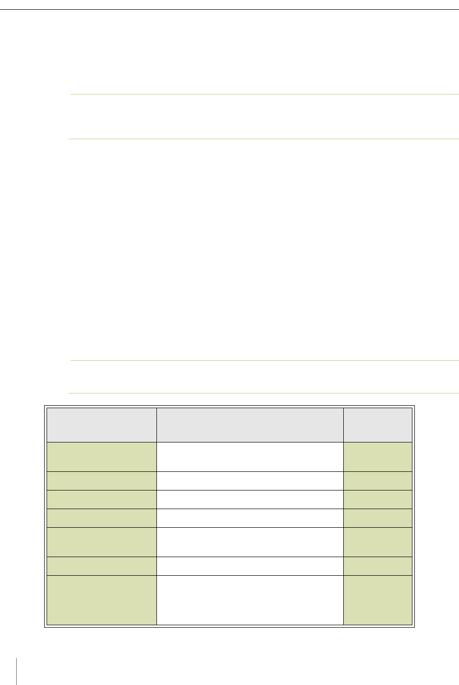
An SPP can be directly interfaced to a traffic signal controller through an APCC.
When this is the case, power to the SPP is drawn from the traffic controller as
shown in the following figure.
Chapter 4
14 Access Points Controller Card (APCC)
Installation Guide Sensys Networks, Inc.
Figure 4.1. SPP radio powered from a traffic controller
Acquiring Power From Traffic Controller Using an Isolator
An optional isolator can be used when acquiring power from the traffic controller
as shown in following figure.
Figure 4.2. SPP radio powered from a traffic controller

SPP Installation Considerations
Access Points Controller Card (APCC) 15
Sensys Networks, Inc. Installation Guide
Voltages
The APCC uses the following voltages drawn from one of the following sources:
20VDC – 28 VDC (24 VDC nominal) – typically supplied from a nearby traffic
controller cabinet or power pole
10VDC – 16 VDC (12 VDC nominal) – typically supplied from a solar panel
Cabling
Standard Ethernet compatible, outdoor rated, 4-pair CAT5 or better cable is
required. The maximum cable length is 328 feet (100 meters) or 2,000 ft (610
meters) with isolator. The cable should be terminated with RJ45 connectors
according to the TIA/EIA 568-B specification when it is installed.
Collecting Data From the APCC
The APCC automatically collect detection events and, depending on the network
design, forward them to upstream traffic information systems and management
servers via an IP network connection. An on-board Ethernet network interface
facilitates this. In situations where a wired network connection is not available, a
modem supporting either GSM-based or CDMA-based cellular services may be
added.
The following connection models are supported for IP communications:
Connection via a wired network path – for example, bench configuration
prior to installation, field access based on patching a technician's laptop to the
APCC via an Ethernet cable, or an available wide area network connection.
Connection via a wireless network path – for example, using GSM cellular
networks (EDGE/GPRS data services) or CDMA cellular networks (1xRTT data
services).
Additionally, event data may be forwarded to a local traffic signal controller via an
APCC. This interface converts event data to the signal pattern required by the
traffic controller.
Determining the Location of the SPP
The physical location of the SPP is the primary determinant of communications
quality and, as such, the network's overall usefulness and reliability. Selecting a
location involves several factors (including other local RF transmissions) that may
make pre-assigned locations problematic.
Optimal Location Criteria
Optimal locations for SPP digital radios meet all of the following criteria:
are high enough to promote high quality RF communications on a sustained
basis
allow a line-of-sight path to (optional) isolator, wireless sensors, and repeaters

Chapter 4
16 Access Points Controller Card (APCC)
Installation Guide Sensys Networks, Inc.
are within recommended distances for the APCC, (optional) isolator, and
wireless sensors
allow the SPP to be mounted with its bulkhead connector and cellular antenna
(if applicable) pointed toward the ground
are within specified cable length limits
do not submit the SPP to avoidable vibration, shaking, or movement
are reasonably accessible to field support personnel

Access Point Controller Card (APCC) 17
Sensys Networks, Inc. Installation Guide
Chapter 5
APCC Installation Procedures
This chapter provides the instructions for installing and cabling an APCC.
Overview
Installation and setup of APCC occurs at the site of the traffic controller and
consists of the following activities:
Determining the Card ID and Setting it via Circuit-board Dip Switches SW1 and SW2
Determining the Controller Type and Setting it via Circuit-board Dip Switch SW1
Connecting the Cables to Each Device
Determining the Card ID and Setting it via Circuit-board
Dip Switches SW1 and SW2
APCC and EX cards are addressed via a value known as the Card ID. A Card ID
must be unique to the network and is required for communication between the
APCC and the EX cards.
Card ID values are expressed as: [ shelf number ] - [ slot number ].
Both shelf-number and slot-number must be determined to create a Card ID.
Some traffic controllers designate the card address, while others (typically older
models) do not. In the latter case, the installer assigns the Card ID ensuring that it
is unique to the network.
Follow the procedures in this section for each contact closure card to be installed.
Chapter 5
18 Access Point Controller Card (APCC)
Installation Guide Sensys Networks, Inc.
Factory Default Card ID
Card IDs are implemented on Sensys Networks contact closure cards via two dip
switches found on the side of the card. In this guide, the switches – named SW1
and SW2 respectively – are referred as circuit-board dip switches to differentiate
them from other dip switches on the front-panel of contact closure cards.
A default Card ID of “03-15” is assigned at the factory and is shown in the
following figure.
NOTE:
On the card, switches SW1 and SW2 are not as close to one another as shown in the figure.
Figure 5.1. Default card ID (all dips down)
Before proceeding, ensure that switches SW1 and SW2 are set as in Figure 5.1 and,
additionally, that all front-panel switches are in the right-hand position.
Querying the Backplane for an Assigned Address
The APCC support an operating mode (called X mode) that queries the traffic
controller backplane for an address. Because it can be difficult to determine from
visual inspection if the backplane dictates card addresses, the standard practice is
to use X mode to see if this is the case.
X mode uses the four front-panel channel LEDs to visually indicate the backplane
address assigned by the controller (if any). (Refer to Appendix A: X Mode LED
Displays for Slot Numbers for a figure that depicts how the channel LEDs are used.)
Follow these steps to use X mode to query the controller for a card address:
1. Verify that the APCC is set to its default Card ID and that all front-panel
switches are in the right-hand position.
2. Reset the APCC by pressing the master reset button (located on front-panel
next to channel LEDs) or removing the unit from the cabinet and re-inserting
it.
3. Observe the front-panel channel LEDs. Match the pattern of lighted LEDs
with the figure in Appendix A: X Mode LED Displays for Slot Numbers.
The address value that matches the LED display pattern (from Appendix A) is the
slot number component of the Card ID.

APCC Installation Procedures
Access Points Controller Card (APCC) 19
Sensys Networks, Inc. Installation Guide
NOTE:
After the cabinet backplane is queried for an address, be sure to take the APCC card out of
X-mode by setting front-panel dip switch 2 to the right, and resetting the card.
Setting the Slot-Number With Circuit-board Dip Switch SW2
Circuit-board dip switch SW2 implements the slot number component of the Card
ID. Set switch SW2 to match the value derived from the figure in Appendix A
subject to the exception noted below.
Exception
In cases where the controller does not assign an address, the installer will see a
front-panel channel LED display pattern indicating an address of 15 (all LEDs
lighted). This address can be used for the first contact closure card installed.
However, subsequent cards must be given a different address – arbitrarily
assigned by the installer. Any value between 0 and 15 may be used; remember that
Card IDs must be unique for the network.
Refer to Appendix C: Circuit-board Dip Switch SW2 Settings for a figure that illustrates
how to set switch SW2 to values between 0 and 15.
Setting the Shelf-Number With Circuit-board Dip Switch SW1
Circuit-board dip switch SW1 implements the shelf number component of the
Card ID. Shelf numbers are assigned by the installer after visually inspecting the
cabinet.
The convention is to consider the top-most shelf in the card rack as shelf zero and
to increment the shelf number by one for each shelf below the top-most shelf. For
example, the bottom shelf in a cabinet of four shelves would be considered shelf
three.
Set circuit-board dip switch SW1 to the shelf number using the two left-most
switches. Refer to Appendix B: Circuit-board Dip Switch SW1 Settings for a figure that
illustrates how to set switch SW1 to values between 0 and 3.
Determining the Controller Type and Setting it via Circuit-
board Dip Switch SW1
At the factory, contact closure cards are set for use with Type 170, Type 2070
(without status relays), or NEMA TS1 traffic controllers. This setting is made with
switch three of circuit-board dip switch SW1.
Verify the controller type and set dip three of circuit-board dip switch SW1 as
needed. Use the figure in Appendix B: Circuit-board Dip Switch SW1 Settings as a guide
for setting switch three of SW1 to the proper value.

Chapter 5
20 Access Point Controller Card (APCC)
Installation Guide Sensys Networks, Inc.
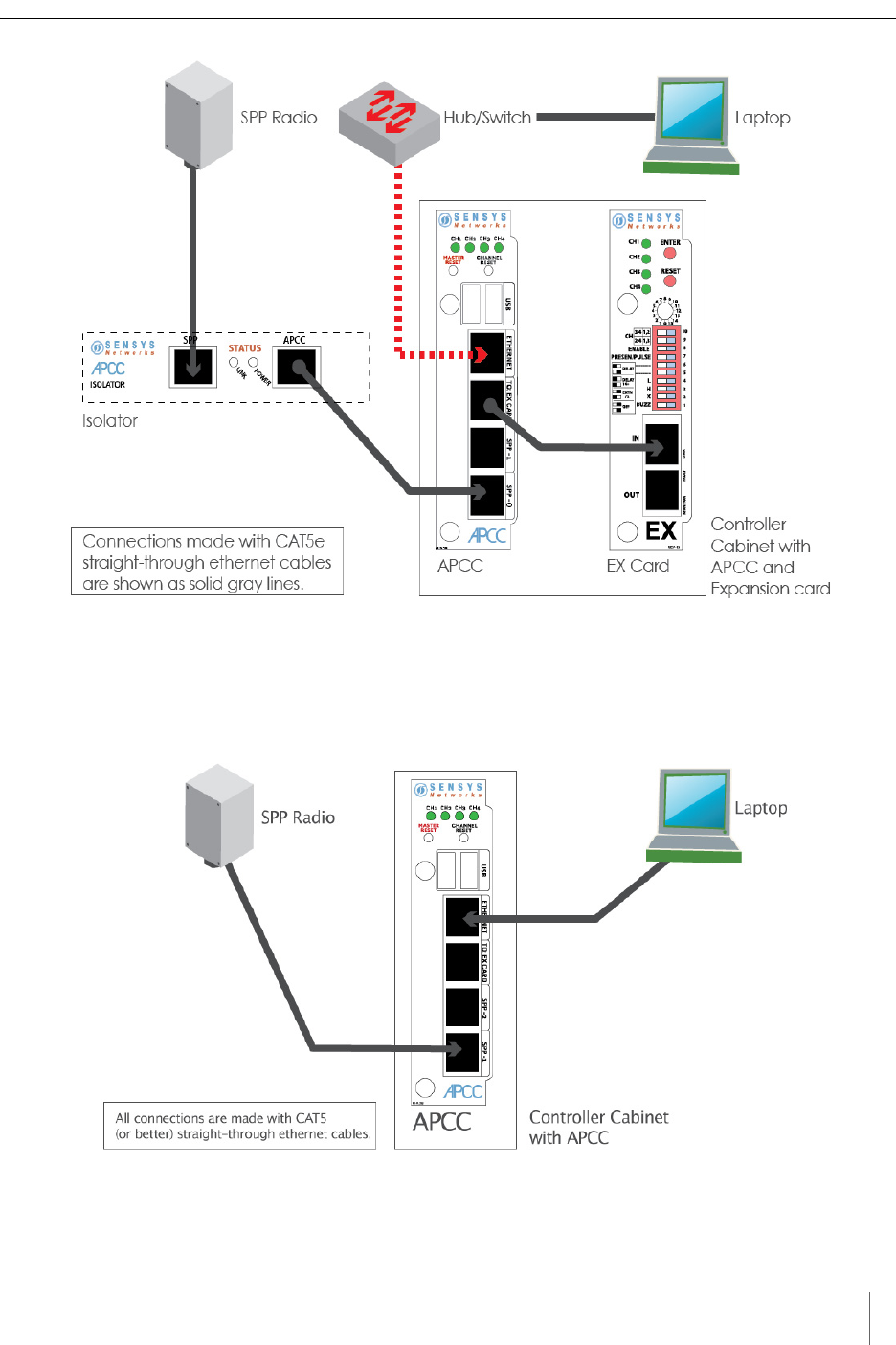
Connecting the Cables to Each Device
Cable the devices according to the steps below. Refer to the section Cabling Summary
below for figures that depict the supported cabling schemes.
NOTE:
The steps below are for a system configuration that contain an optional isolator, and an EX
card. A figure of a minimal cabling configuration is shown in the Cabling Summary section.
1. Connect a straight-through CAT5 (or better) cable, terminated with RJ45
connectors to the SPP and the port labeled “SPP” on the isolator.
2. Connect a straight-through CAT5 (or better) cable, terminated with RJ45
connectors to the jack labeled “APCC” on the isolator and the port labeled
“SPP-1 or SPP-0” on the APCC.
The green LED labeled “POWER” on the APCC should light.
When communication is established between the SPP and the APCC, the LED
labeled “LINK” blinks periodically. When data from the radios are being
transmitted to the APCC, a periodic blinking occurs.
3. Connect a straight-through CAT5 (or better) cable, terminated with RJ45
connectors to the jack labeled “TO: EX CARD” on the APCC and the port
labeled “IN” on the EX card.
4. To connect a laptop PC to the system, connect a straight-through CAT5 (or
better) cable, terminated with RJ45 connectors from the laptop to the port
labeled “ETHERNET” on the APCC.
5. To connect the APCC to a hub, bridge, switch, router or similar device, use a
cross over Ethernet cable.
NOTE:
Steps 4 and 5 are optional. Connect the laptop PC to the APCC to configure or
manage the contact closure cards through TrafficDOT, the system management
tool from Sensys Networks.
APCC Installation Procedures
Access Points Controller Card (APCC) 21
Sensys Networks, Inc. Installation Guide
Figure 5.2. Cabling an isolator and hub or switch to an APCC
Cabling Summary
The cabling to connect an APCC, SPP, and laptop is shown in the following figure.
Figure 5.3. Cabling a PC or laptop

Chapter 5
22 Access Point Controller Card (APCC)
Installation Guide Sensys Networks, Inc.
Access Point Controller Card (APCC) 23
Sensys Networks, Inc. Installation Guide
Chapter 6
SPP Installation Procedures
This chapter provides the instructions for installing and mounting an SPP.
Installing an SPP consists of the following:
Attaching the square surface mounting ball plate to an available vertical
surface
Attaching the SPP to the surface mounting ball plate via the double socket arm
Mounting hardware is included in the universal mounting kit provided with each
SPP.
Tools Required for SPP Installation
The following tools are required for installing an SPP:
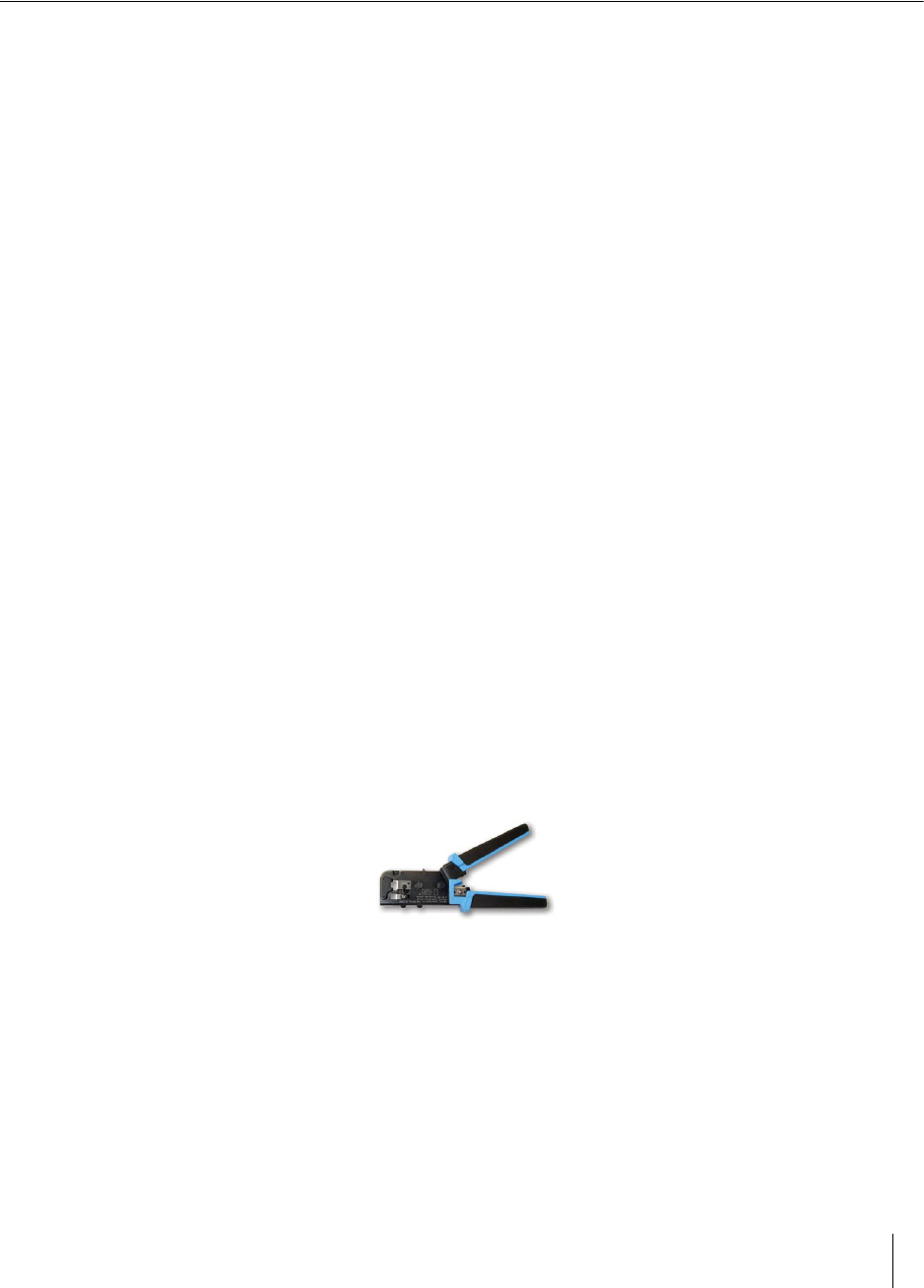
RJ45 crimp tool – to terminate the SPP cable. (Sensys Networks recommends
the EZ-RJPRO P/N 100044 from Platinum Tools.)
Figure 6.1. EZ-RJPRO
RJ45 connectors – rated Cat5e or better; to terminate the SPP cable
Cat5e cable continuity line tester – to validate cable continuity
Outdoor rated Cat5e Ethernet cable – to build the SPP cable; length is
determined by the distance between the SPP mounting location and the source
of power (typically a controller cabinet, solar panel or other available source)

Chapter 6
24 Access Point Controller Card (APCC)
Installation Guide Sensys Networks, Inc.
2 straight-through Cat5 Ethernet cables – each approximately three feet in
length; used in installations where the SPP is connected to a contact closure
card in a controller cabinet.
Additional straight-through Cat5 Ethernet cables – optional; each
approximately one foot in length; these cables are used to daisy chain multiple
contact closure cards. Required only in the case of multiple CC/EX cards.
Lift truck – to install the SPP 16 – 30 feet above the road surface
Screwdriver – combination flat and Phillips head ends
Universal mounting kit – double-socket arm holds the SPP. (Kit can be
purchased from Sensys Networks.)
Clamp band kit – for attaching double-socket arm to mounting pole. (Kit
supplied by Sensys Networks.)
Pliers – used to work the clamp band
Wire cutters – used to cut the clamp band
Step-by-Step Procedures
The square surface mounting ball plate can be installed on any available vertical
surface sufficient to support the SPP including poles, walls or beams. This section
provides procedures for pole installation; considerations for wall or beam
mounting follow this section.
Installing the Mounting Plate on Poles
When attaching the square surface mounting ball plate to a pole, the clamp band
is used to secure the ball plate to the pole. (Refer to Appendix A for more
information about working with the clamp band.)
Follow these steps to perform the installation:
1. Use the measuring tape to determine the circumference of the pole that will
hold the ball plate.
2. Subtract four inches from the measured circumference and cut the band to
that length. Cut the band through the center of the nearest round hole.
3. Feed the clamp band through the square ball plate using the custom clamp
holes (refer to the following figures) until the square ball plate is at the center
of the band. Attach the fastener to one end of the band by diagonally inserting
the end.
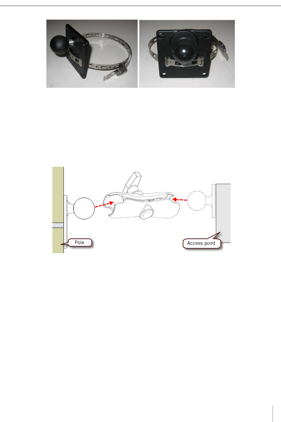
SPP Installation Procedures
Access Point Controller Card (APCC) 25
Sensys Networks, Inc. Installation Guide
Figure 6.2. Clamp band threading through surface mounting ball plate
4. Use the cloth to clean the area of the pole that will meet the ball plate. Remove
the double stick tape cover from the back of the plate, wrap the clamp band
around the pole, and attach the second (non-engaged) end of the fastener.
Tighten the clamp to secure it.
5. Attach the double socket arm to the square ball plate.
6. Attach the SPP ball plate to the other end of the double socket arm.
Figure 6.3. Double socket arm installation
7. Point the front of the SPP toward the wireless sensors and tighten the double
socket arm to secure the SPP digital radio's position.
Installing the Mounting Plate on Walls
When attaching the square surface-mounting ball plate to a flat surface, the clamp
band is not used. Instead, attach the ball plate to the surface with screws using
each of the four corner holes.
Installing the Mounting Plate on Beams
When attaching the square surface-mounting ball plate to a beam, the clamp band
is not used. Instead, attach the ball plate to the beam with beam clamps using two
of the four corner holes. Beam clamps are available from Sensys Networks.
Chapter 6
26 Access Point Controller Card (APCC)
Installation Guide Sensys Networks, Inc.
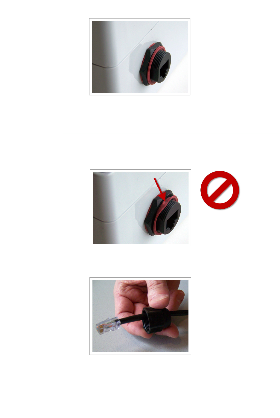
Determining the Type of SPP Radio Bulkhead Connector
The bulkhead connector mechanism used on SPPs from Sensys Networks is one
type:
Hex-head type
Refer to the following figure to determine the proper installation procedure.
SPP Radio Bulkhead Connector
Figure 6.4. SPP radio bulkhead connector type: hex-head
Figure 6.4 shows the SPP hex-head connector. Follow the procedures in the
section Connecting the Cable to an SPP Radio with the Hex-head Connector to connect the
Ethernet cable to SPPs using this connector type.
Connecting the Cable to an SPP Radio with the Hex-head
Connector
Follow the steps in this section to properly connect the cable to the SPP via the
hex-head bulkhead connector.
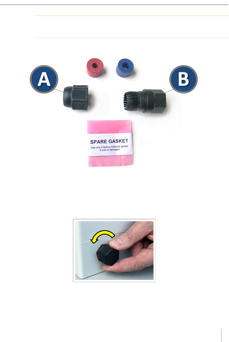
Components
Open the bulkhead connector kit and arrange the components as shown in the
following figure. In the figure, the two principal connectors are labeled A and B
respectively.
N
OTE
:
Two cable bushings are included; choose one to fit the outside diameter of the Ethernet
cable being connected to the SPP. Additionally, a spare gasket is included; use the gasket
only if the factory installed gasket is lost or visibly damaged.
SPP Installation Procedures
Access Point Controller Card (APCC) 27
Sensys Networks, Inc. Installation Guide
N
OTE
:
Figures in this section depict only one of the bushings. The procedures apply equally to
either bushing.
Figure 6.5. Components used with the hex-head bulkhead connector
Step-by-Step Procedures
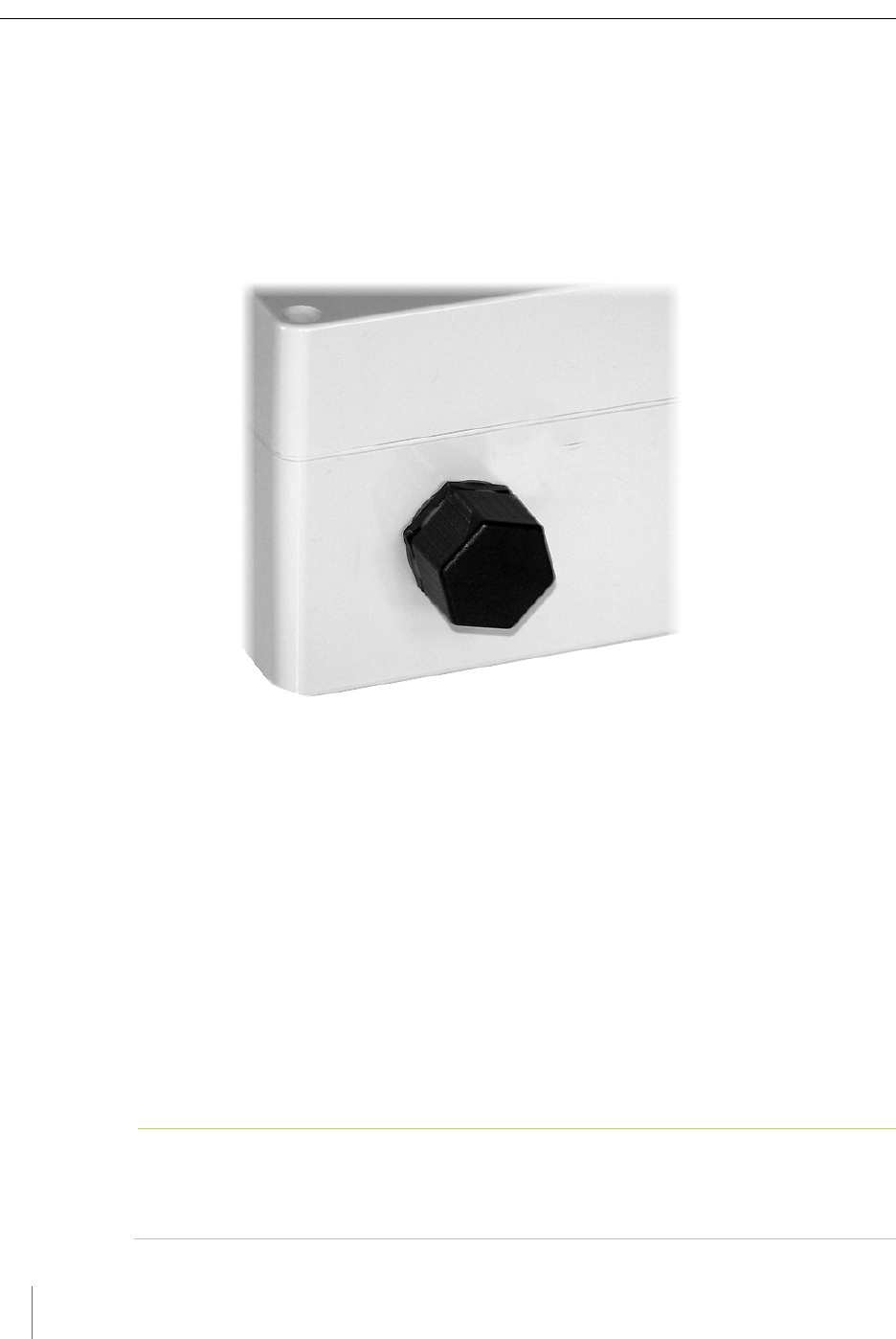
1. Remove the factory installed hex-head cap from the bottom of the SPP and set
it aside. The cap may be discarded after the cable has been completely
connected.
Figure 6.6. Remove the factory-installed cap
2. Carefully inspect the factory installed gasket seated on the bulkhead connector.
Ensure the gasket is seated smoothly and uniformly on the connector with the
ridged edge of the gasket facing outward.
Chapter 6
28 Access Point Controller Card (APCC)
Installation Guide Sensys Networks, Inc.
Figure 6.7. Inspect the factory-installed gasket
Replace the gasket if it does not uniformly seat or shows signs of fatigue or
wear. (When replacing an SPP, always use a new gasket.)
N
OTE
:
Use gaskets from Sensys Networks only. Never substitute a different gasket;
doing so exposes the device to environmental risk and voids the product warranty.
Figure 6.8. Replace damaged or used gaskets
3. Thread the cable through the Connector A as shown in the following figure.
Figure 6.9. Thread cable through connector A
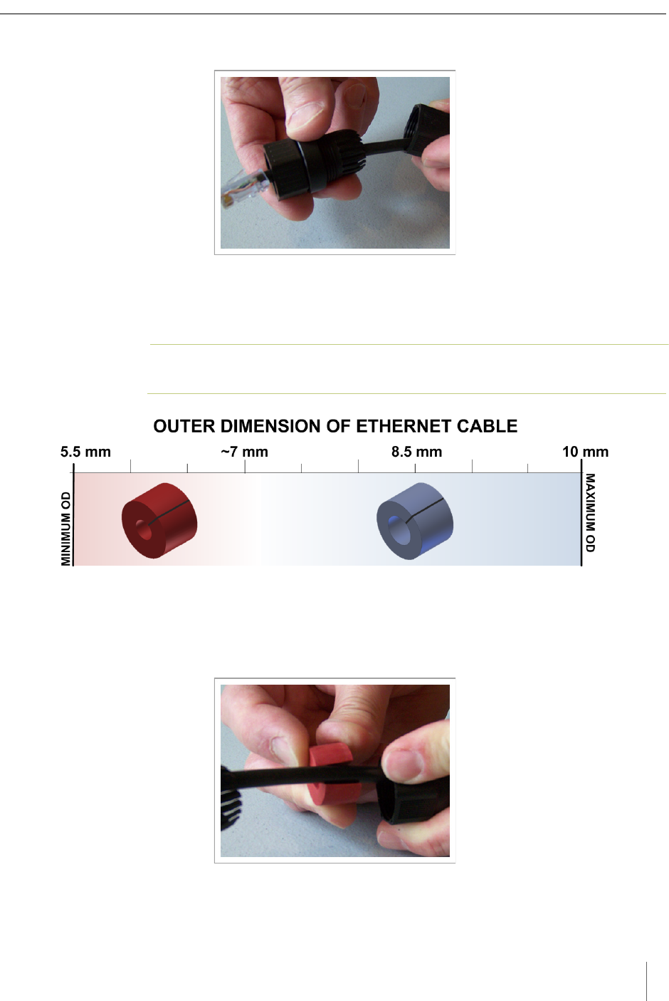
SPP Installation Procedures
Access Point Controller Card (APCC) 29
Sensys Networks, Inc. Installation Guide
4. Thread the cable through Connector B as shown in the following figure.
Figure 6.10. Thread cable through connector B
5. Inspect the outer diameter (OD) of the Ethernet cable. Use the following chart
to select one of the provided bushings based on the cable OD.
N
OTE
:
Use only one bushing. Discard the other bushing after the job is complete.
Figure 6.11. Ethernet cable bushing chart (not to scale)
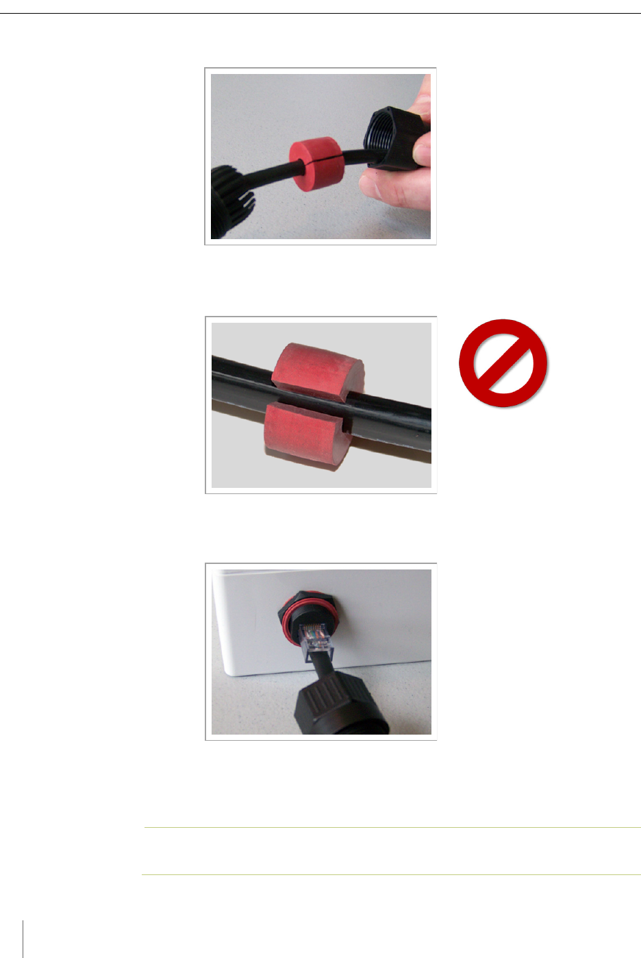
6. Fit the bushing onto the cable between Connectors A and B as shown in the
following figure. Proper fit is achieved when the bushing fully closes around
the cable with no gap at the cut.
Figure 6.12. Fit bushing onto cable between connector A and connector B
Chapter 6
30 Access Point Controller Card (APCC)
Installation Guide Sensys Networks, Inc.
Proper Fit (little to no gap between edges of cut)
Figure 6.13. Correct fit: bushing closes fully around cable with little or no gap
Improper Fit (gap between edges of cut)
Figure 6.14. Incorrect fit: bushing does not close fully around cable leaving large gap
7. Connect the cable to the RJ45 input jack on the bottom of the SPP.
Figure 6.15. Connect cable to input jack
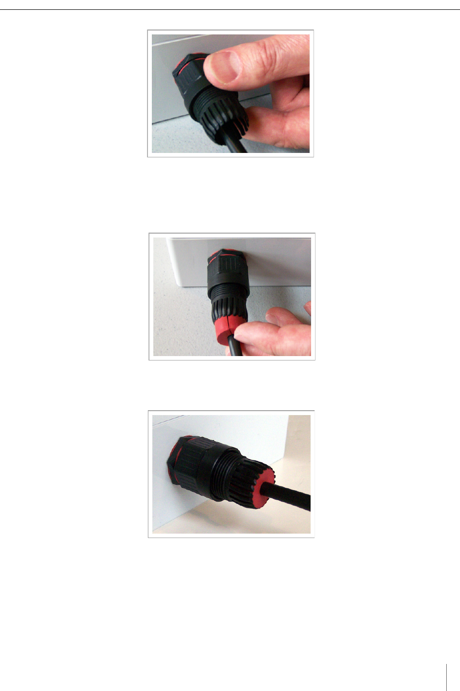
8. Thread Connector B onto the hex-head nut on the bottom of the SPP and
tighten by hand until it no longer turns easily.
N
OTE
:
Snug Connector A down by hand. Do not over-tighten or use tools.
SPP Installation Procedures
Access Point Controller Card (APCC) 31
Sensys Networks, Inc. Installation Guide
Figure 6.16. Thread connector B onto the SPP and hand tighten
9. Slide the cable bushing toward the SPP and fully insert it into the guide fingers
on Connector B as shown in the following figure. Proper fit is achieved when
the edge of the bushing is flush with the edge of the guide fingers.
Figure 6.17. Slide cable bushing fully into connector B
Proper Fit (bushing fully seated into guides)
Figure 6.18. Proper fit of cable bushing into connector B
Chapter 6
32 Access Point Controller Card (APCC)
Installation Guide Sensys Networks, Inc.
Improper Fit (bushing poorly seated into guides)
Figure 6.19. Improper fit of cable bushing into connector B
10. Thread Connector A onto Connector B and tighten by hand until it no longer
turns easily.
N
OTE
:
Snug Connector A down by hand. Do not over-tighten or use tools.
Figure 6.20. Thread connector A onto connector B and hand tighten
11. Inspect the seating of the bushing by looking at it from the exposed cable end
of Connector A. Proper fit is achieved when all of the following conditions are
met:
bushing edge is recessed 1/8” to 1/4” below the lip of Connector A
bushing face is smooth - not puckered or pinched
bushing face does not protrude out of Connector A
SPP Installation Procedures
Access Point Controller Card (APCC) 33
Sensys Networks, Inc. Installation Guide
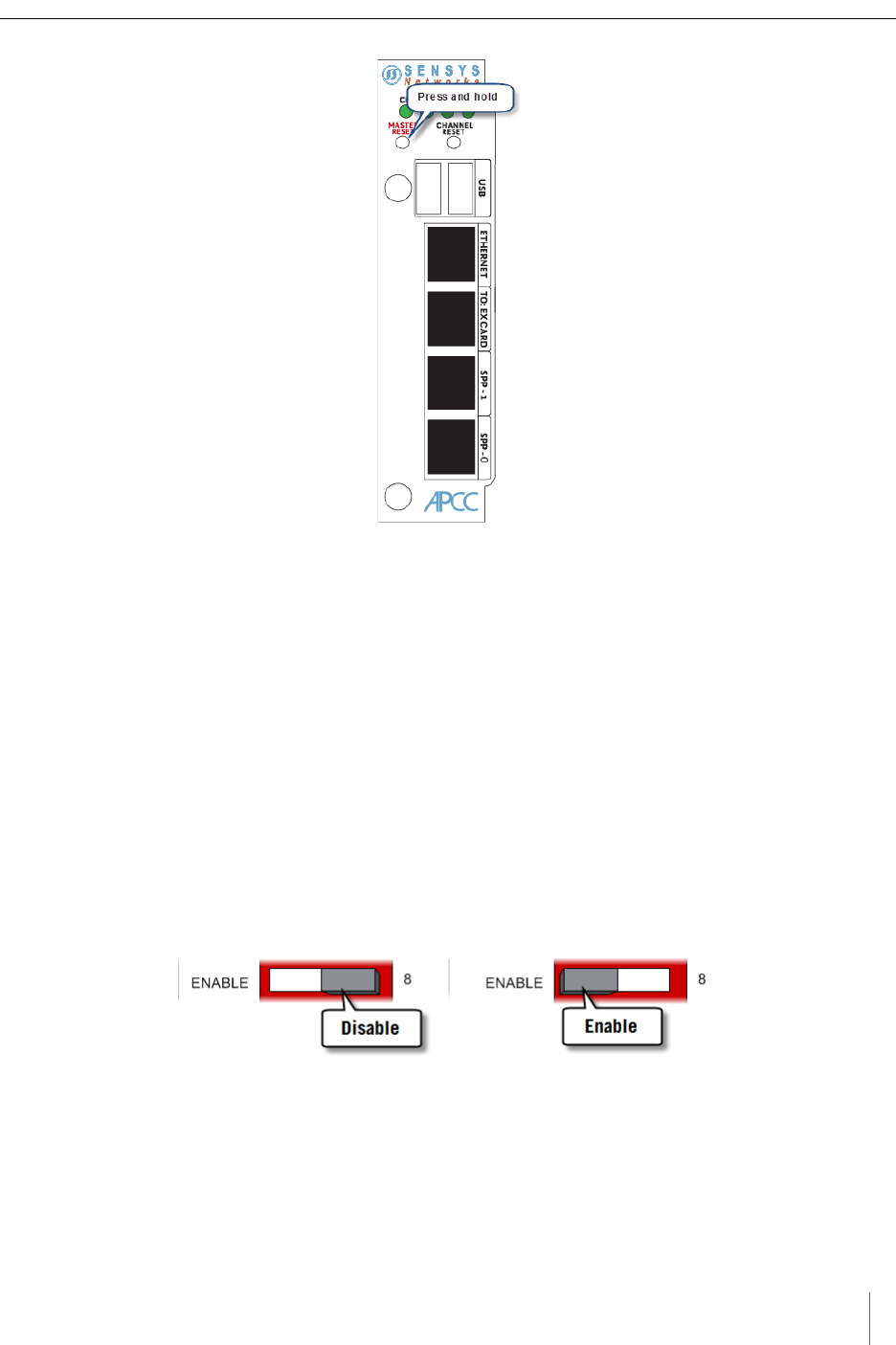
Proper Fit (recessed bushing, smooth face)
Figure 6.21. Proper fit of the cable bushing inside connector A
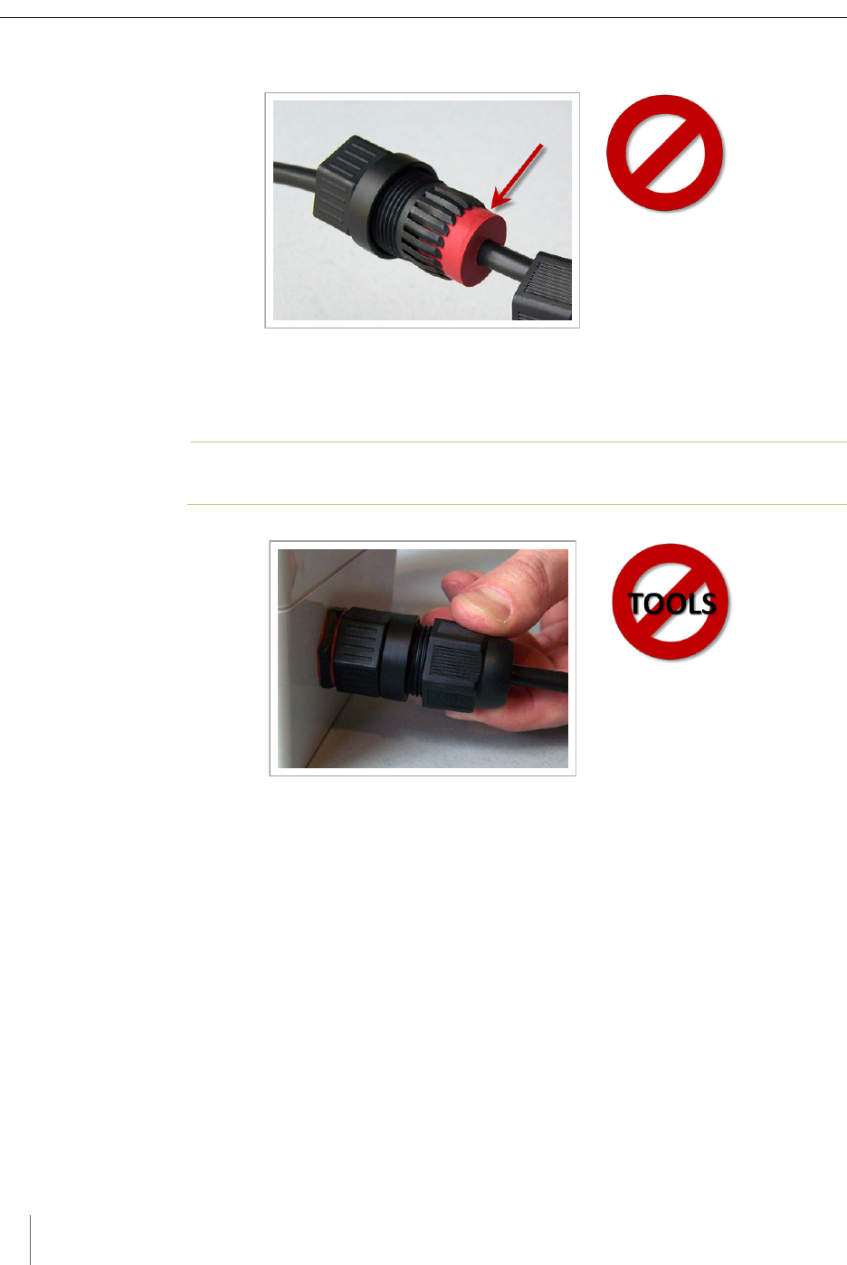
Improper Fit (bushing not recessed, pinched edge, mushroomed face)
Figure 6.22. Improper fit of the cable bushing inside connector A
Figure 6.23.
Removing the Cable Connection
Perform procedure above in reverse to remove the cable from the SPP.

Chapter 6
34 Access Point Controller Card (APCC)
Installation Guide Sensys Networks, Inc.

Access Point Controller Card (APCC) 35
Sensys Networks, Inc. Installation Guide
Chapter 7
Configuration
This chapter explains how to configure channels and other operating elements of
contact closure cards in the APCC and EX cards.
N
OTE
:
Prior to configuring channels, ensure that each contact closure card has been given a
unique Card ID. Refer to the Identifying the SPP and Sensors section in the Installation
Considerations chapter for more information.
Overview
Each channel of an APCC or EX card is configured separately. Configuring a
channel consists of the following activities:
Enabling (or disabling) the channel
Specifying the channel mode
Setting a presence mode modifier (optional)
Specifying the type of communication used to disclose channel status
Additionally, after channel configuration is completed, TrafficDOT is used to
define the sensor-to-channel mappings stored on the APCC.
After all configuration work is complete, including definition of sensor-to-channel
mapping entries for all channels, Sensys Networks recommends verifying the
operation of each channel using the front-panel channel LEDs.

Chapter 7
36 Access Point Controller Card (APCC)
Installation Guide Sensys Networks, Inc.
Configuration Methods
Configuration occurs through two mutually exclusive choices: (i) the card's front-
panel interface or (ii) with TrafficDOT, the system management application from
Sensys Networks. This chapter includes the following sections:
Configuring Channels With the Front-Panel Interface
Starting TrafficDOT and Connecting to an APCC
Configuring Channels with TrafficDOT
Defining Sensor-to-Channel Mappings
Exiting TrafficDOT
Configuring Channels With the Front-Panel Interface
After completing the configuration of all channels, continue setting up the APCC
by starting the TrafficDOT software utility and defining the sensor-to-channel
mappings.
N
OTE
:
If the APCC is configured with TrafficDOT, this section can be ignored.
General Procedure
The general procedure for configuring channels via the front-panel is provided
below. Examples of specific configuration activities are included in the following
sections. The steps are as follows:
1. Select a channel.
2. Move dip switches (as required) to represent the desired settings.
3. Press the MASTER RESET button on the card front-panel and hold it down
for a minimum of five seconds.
Configuration
Access Point Controller Card (APCC) 37
Sensys Networks, Inc. Installation Guide
Figure 7.1. Configuration via the front-panel interface
Saving the Configuration
After the MASTER RESET button is pressed, the LINK LED flashes. When the
flashing stops, the settings have been stored in flash memory.
The sections below give examples of setting specific configurations via the front-
panel interface. The procedures may be performed in any order or combination.
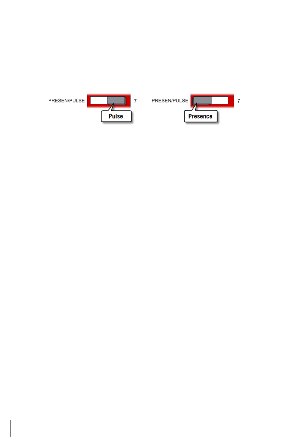
Enabling / Disabling a Channel
APCC and EX cards ship with channels one and two enabled. Sensys Networks
recommends explicitly disabling all unused channels.
Follow these steps to enable or disable a channel.
1. Position front-panel dip switch 8 to the left to enable (to the right to disable)
the channel.
Figure 7.2. Enabling (disabling) a channel with front-panel dip switch 8
2. Press the Enter button for five seconds to save the configuration to flash
memory or continue with other configuration activities described in this
section.
Chapter 7
38 Access Point Controller Card (APCC)
Installation Guide Sensys Networks, Inc.
Specifying the Channel Mode
Contact closure cards operate in either pulse or presence mode. (Refer to the
Sensys Networks VDS240 Wireless Vehicle Detection System Reference Guide for
information about the operating modes.)
Follow these steps to specify the operating mode of the channel.
1. Position front-panel dip switch 7 to the left to select presence mode or to the
right to select pulse mode.
Figure 7.3. Selecting the channel operating mode with front-panel switch 7
2. Press the Enter button for five seconds to save the configuration to flash
memory or continue with other configuration activities described in this
section.
Setting a Presence Mode Modifier (Optional)
Channels operating in presence mode may use a modifier to delay the onset of or
extend the duration of a contact closure. The modifier type and scope is specified
using front-panel dip switches five and six together. (Refer to the Sensys
Networks VDS240 Wireless Vehicle Detection System Reference Guide for more
information.)
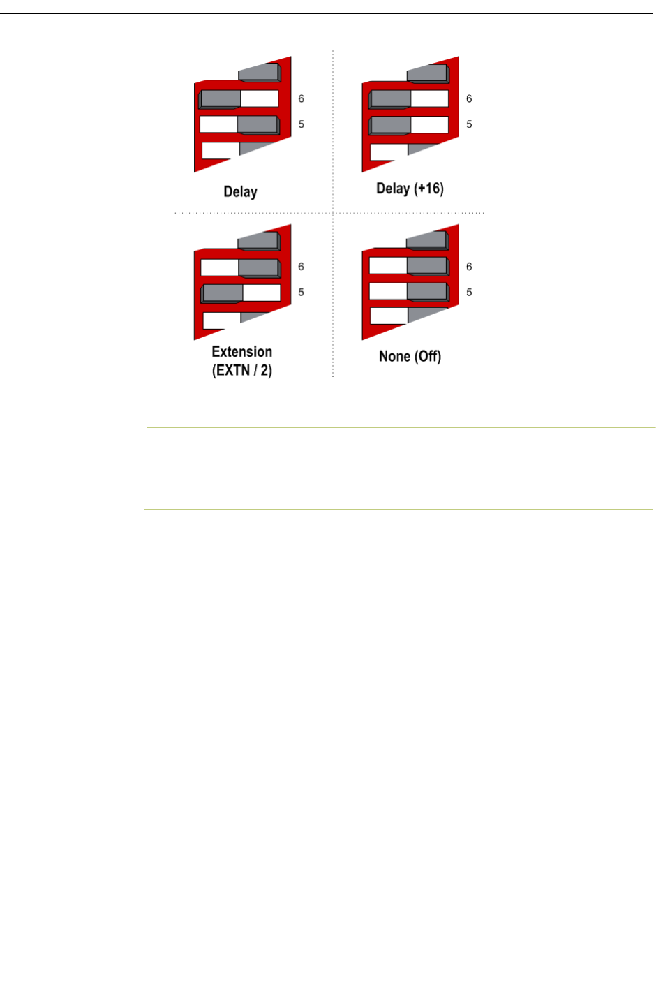
Using Delay and Extension
When Delay or Extension are specified, the rotary dial is used to articulate the
numeric value associated with the parameter.
When Delay is specified, the value set on the rotary dial is taken directly. This
allows the 16-step rotary switch to represent values from 0 to 15.
When Delay+16 is specified, the value set on the rotary dial is incremented by 16.
This allows the 16-step rotary switch to represent values from 16 to 31.
When Extension (EXTN / 2) is specified, the value set on the rotary dial is divided
by 2. This allows the 16-step rotary switch to represent values from 0 to 7.5 in ½
step increments.
Specify a contact closure delay or extension for channels operating in presence
mode by following these steps:
1. Position front-panel dip switches 5 and 6 and the front-panel rotary switch to
reflect the desired modifier and scope value. Use the figure below as a guide.
Configuration
Access Point Controller Card (APCC) 39
Sensys Networks, Inc. Installation Guide
Figure 7.4. Setting a delay or extension with front-panel dip switches 5 and 6 (rotary switch not shown)
N
OTE
:
This step is optional; set both dips to right-hand position to disable the feature.
Additionally, front-panel switches 5 and 6 are ignored for channels operating in
pulse mode.
2. Press the Enter button for five seconds to save the configuration to flash
memory or continue with other configuration activities described in this
section.
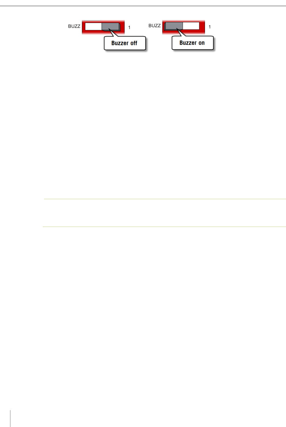
Specifying the Type of Communication Used by the Channel
Status Monitor
Contact closure cards indicate the status of each channel via the front-panel LEDs.
The state of an LED corresponds directly to the channel state. When the LED is on,
the channel relay is closed indicating a call. When the LED is not on, the channel
relay is open.
Additionally, a contact closure card can be set such that closed channel relays
activate an audible tone (buzzer) as well as the front-panel LED for the channel.
The audible channel status tone is set via front-panel dip switch one as follows:
1. Position front-panel dip switch 1 to enable or disable the audible channel
status monitor. Use the figure below as a guide.
Chapter 7
40 Access Point Controller Card (APCC)
Installation Guide Sensys Networks, Inc.
Figure 7.5. Setting the channel monitor buzzer with front-panel dip switch 1
2. Press the Enter button for five seconds to save the configuration to flash
memory or continue with other configuration activities described in this
section.
Starting TrafficDOT and Connecting to an APCC
TrafficDOT is a configuration manager and monitoring tool for an access point
and all its associated devices (sensors, repeaters, and contact closure cards).
TrafficDOT provides a graphical user interface (GUI) to the network's devices,
settings, and operations. The GUI simplifies both configuration and management
of installations.
TrafficDOT requires an IP network connection to the APCC. When configuring
contact closure cards, the connection is made by cabling a laptop to an APCC or
EX card. (Refer to the section Cabling Summary in Chapter 5 for additional
information.)
N
OTE
:
Refer to the TrafficDOT Set Up and Operating Guide for a more information on using
TrafficDOT with the Sensys Networks Wireless Vehicle Detection System.
Connect to the APCC with TrafficDOT by following these steps:
1. On a Windows laptop or PC, start TrafficDOT by clicking its icon. TrafficDOT's
Main window opens with the Connect window open in front of it.
Configuration
Access Point Controller Card (APCC) 41
Sensys Networks, Inc. Installation Guide
Figure 7.6. TrafficDOT Main and Connect windows
2. Type the IP address of the APCC into the IP Address field and accept the
default value in the TCP Port field. Click Connect.
3. After clicking Connect, wait a moment for the Main window.
Figure 7.7. Map view
Chapter 7
42 Access Point Controller Card (APCC)
Installation Guide Sensys Networks, Inc.
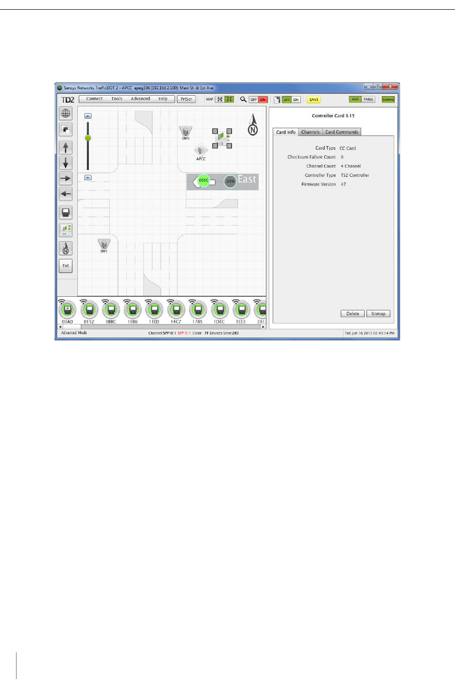
Configuring Channels with TrafficDOT
To select an controller card for configuration, click a controller card on your image
map. The Controller Card Configuration window displays.
Figure 7.8. Controller Card Configuration window
Entering controller card information
To enter controller card information, select the controller card image on the map
and enter the information into the Configuration Panel, or drag and drop a sensor
onto the controller card icon, and then enter the information.
Configuration
Access Point Controller Card (APCC) 43
Sensys Networks, Inc. Installation Guide
Figure 7.9. Controller Card Channels tab
Configuring Channel State
Contact closure card channels are independent of one another and are individually
configured. Each channel occupies one of the following states:
Enabled – the channel is operational; Sensor event data collected by the access
point is transmitted to the contact closure card.
Disabled – the channel is not operational. (When a channel is disabled, its
contact closure relay and status relay are continuously open.)
The factory default configuration enable channels one and two. Ensure that any
unused or unavailable channels are disabled.
Configuring Channel Mode
Enabled channels operate in one of the following modes:
Pulse – the contact closure relay pulses for 0.125 seconds each time the leading
edge of a vehicle is detected.
Presence – the contact closure relay remains closed while a vehicle is detected.
The factory default setting is pulse mode.

Chapter 7
44 Access Point Controller Card (APCC)
Installation Guide Sensys Networks, Inc.
Configuring Presence Mode Modifier
The behavior of a channel operating in presence mode may adjusted by applying
one of the following modifiers:
Delay – defers the onset of the contact closure by a specified duration. If a
vehicle moves off of the sensor before the specified delay expires, the contact
does not close. Delay is expressed in seconds from zero to 31.
Extension – increases the duration of the contact closure by a specified
increment. Extension is expressed in half-seconds from zero t0 7.5.
The modifiers do not apply to channels operating in pulse mode.
Configuring Channel Holdover Duration
The Channel Holderover parameter allows an extension to the channel holdover
duration when it is activated by the events from a particular sensor. Values from
0.0 to 0.75 are available for selection.
Defining Sensor-to-Channel Mappings
To map sensors to an APCC or EX card, perform the following steps:
1. Select a sensor from the image map.
2. Open the Card Addresses window by clicking the Card Addresses tab.
The Extension entry extends the duration of an APCC or EX card on a per-sensor
basis. The Delay entry delays the duration of an APCC or EX card on a per-sensor
basis; these entries are optional.
The shelf number-slot number is a card address associated with an APCC or EX
card, and channel is between 1 and 4.
Configuration
Access Point Controller Card (APCC) 45
Sensys Networks, Inc. Installation Guide
Figure 7.10. Card Addresses window
3. Select a Shelf number, a Slot number, and a Channel from the drop-down lists.
N
OTE
:
The C button clears the data in that row.
4. Click Apply to save configuration.
N
OTE
:
To assign a sensor to multiple controller channels, supply entries to the additional
Card Addresses areas.
Exiting TrafficDOT
End the TrafficDOT session by selecting Disconnect from the Connect menu.

Chapter 7
46 Access Point Controller Card (APCC)
Installation Guide Sensys Networks, Inc.

Access Point Controller Card (APCC) 47
Sensys Networks, Inc. Installation Guide
Appendix A
X Mode LED Displays for Slot
Numbers
This appendix depicts the channel LED displays when an APCC operates in X
mode.
When a card is configured in X mode, the front-panel channel LEDs display one of
the patterns shown in the figure below. Match the pattern of the front-panel
channel LEDs to a pattern in the figure. Use the corresponding value found under
the heading Address as the slot-number portion of the Card ID. (Refer to Examples
after the figure.)
Appendix A
48 Access Point Controller Card (APCC)
Installation Guide Sensys Networks, Inc.
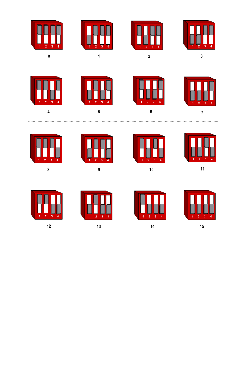
Figure A.1. Channel LED display / slot number combinations
Examples
1. All fours channel LEDs lighted indicates slot number 15.
2. Single lighted LED on channel 2 indicates slot number 4.

Access Point Controller Card (APCC) 49
Sensys Networks, Inc. Installation Guide
Appendix B
Circuit-board Dip Switch SW1
Settings
This appendix depicts combinations of switch settings on the circuit-board dip
switch SW1.
Settings for Shelf Number
The figure below depicts SW1 settings that identify the shelf number portion of the
unique card address.
NOTE:
The small, slide switches are referred to by number [1-4] starting with the left-most switch.
Switches three and four of SW1 are not used in setting the shelf number.
Appendix B
50 Access Point Controller Card (APCC)
Installation Guide Sensys Networks, Inc.
Figure B.1. SW1 settings for shelf number (switches 1 and 2 only)
Settings for TS1 and TS2 Controllers
The following figure depicts SW1 settings that identify the type of traffic
controller. Type 170 and TS1 controllers are set the same way.
Figure B.2. SW1 settings for TS controller types (switch 3 only)
NOTE:
Slide switches one, two, and four are not used in setting the controller type.

Access Point Controller Card (APCC) 51
Sensys Networks, Inc. Installation Guide
Appendix C
Circuit-board Dip Switch SW2
Settings
This appendix depicts combinations of switch settings on the circuit-board dip
switch SW2.
Settings for Slot Number
Circuit-board switch SW2 is used to designate the slot number portion of a
contact closure card's Card ID. The switch combinations and the slot number
values they represent are shown in the following figure. (Slot number values
appear beneath the switches.)
Appendix C
52 Access Point Controller Card (APCC)
Installation Guide Sensys Networks, Inc.
Figure C.1. SW2 settings for slot number

Access Point Controller Card (APCC) 53
Sensys Networks, Inc. Installation Guide
Appendix D
Pre-Installation Worksheets
This appendix provides worksheets for capturing pre-installation information.
Refer to the chapter APCC Installation Considerations for more information.
Configuration Element Options Value
1. Card identifier (Defined by the traffic controller or
installer)
2. Channel 1, 2, 3, 4
3. Channel State Enabled | Disabled
4. Channel Mode Pulse | Presence
4a. Presence Mode Modifier (applicable only to channels in
presence mode)
4b. Modifier Type None | Delay | Expansion
4c. Modifier Duration 0 – 31 seconds in 1 sec increments
(Delay)
0 – 7.5 seconds in 0.5 second
increments (Expansion)
5. Channel Holdover Setting 0 -.75 seconds in .05 second incre-
ments
6. Channel Status
Communications
LED-only | LED and Tone
Other Information (Optional)
APCC identifier (from APCC)

Appendix D
54 Access Point Controller Card (APCC)
Installation Guide Sensys Networks, Inc.
Table 4. Channel configuration worksheet
Table 5. Sensor-to-channel mapping worksheet
Distance from Sensys APCC
(without Isolator)
328 feet (100 meters) - 10BaseT
List of Wireless Sensor for the
Channel
(use SensorIDs of each sensor)
Card ID Channel
(1 - 4)
Sensor
ID
Channel
Extension (opt.)
Location / Lane /
Description (opt.)
Configuration Element Options Value

Access Point Controller Card (APCC) 55
Sensys Networks, Inc. Installation Guide
Appendix E
Contact Closure Card External
Interfaces
This appendix shows the connector pin assignments for the external interfaces of
contact closure master and expansion cards.

Appendix E
56 Access Point Controller Card (APCC)
Installation Guide Sensys Networks, Inc.
Backplane Edge Connections
Pin Function (TS1 mode) Function (TS2 mode)
1Not connected Channel 1 Delay enable
2Not connected Channel 2 Delay enable
3Address 3 Address 3
4Daisy chain RS485 Uplink + Daisy chain RS485 Uplink +
5Daisy chain RS485 Uplink - Daisy chain RS485 Uplink -
6Address 0 Address 0
7Not connected Channel 1 status
8Daisy chain RS485 Downlink + Daisy chain RS485 Down-
link +
9Daisy chain RS485 Downlink - Daisy chain RS485 Down-
link -
10 Address 1 Address 1
11 AC power neutral AC power neutral
12 AC power line AC power line
13 Not connected Not connected
14 Not connected Not connected
15 Address 2 Address 2
16 Not connected Channel 3 status
17 Not connected Not connected
18 Not connected Not connected
19 Not connected Not connected
20 Not connected Channel 2 status
21 Not connected Not connected
22 Not connected Channel 4 status
AGND GND
B24V 24V
CReset input Reset input
DNot connected Not connected
ENot connected Not connected
FChannel 1 collector Channel 1 collector

Contact Closure Card External Interfaces
Access Point Controller Card (APCC) 57
Sensys Networks, Inc. Installation Guide
Table 1.(continued from prior page) Backplane edge connections
Notes
1. Pins G, I, O, and Q are not implemented.
HChannel 1 emitter Channel 1 emitter
JNot connected Not connected
KNot connected Not connected
LChassis Ground Chassis Ground
MAC power neutral AC power neutral
NAC power line AC power line
PNot connected Not connected
RNot connected Not connected
SChannel 3 collector Channel 3 collector
TChannel 3 emitter Channel 3 emitter
UNot connected Not connected
VNot connected Not connected
WChannel 2 collector Channel 2 collector
XChannel 2 emitter Channel 2 emitter
YChannel 4 collector Channel 4 collector
Z Channel 4 emitter Channel 4 emitter
Pin Function (TS1 mode) Function (TS2 mode)
Appendix E
58 Access Point Controller Card (APCC)
Installation Guide Sensys Networks, Inc.
IN RJ45 Connector Pin Assignments
Table 2. IN RJ45 connector pin assignments
OUT RJ45 Connector Pin Assignments
Table 3. OUT RJ45 connector pin assignments
Pin Function on CC Card Function on EX Card
1Not connected Daisy Chain RS485 Downlink +
2Not connected Daisy Chain RS485 Downlink -
3Not connected Daisy Chain Uplink +
4RS485+ Not connected
5RS485- Not connected
6Not connected Daisy Chain RS485 Uplink -
7+48V Not connected
848V Return Not connected
Pin Function on CC and EX Cards
1Daisy Chain RS485 Downlink +
2Daisy Chain RS485 Downlink -
3Daisy Chain RS485 Uplink +
4Not connected
5Not connected
6Daisy Chain RS485 Uplink +
7Not connected
8Not connected